J. Non-Newtonian Fluid Mech., 80 (1999) 183 – 197 Measuring uniaxial extensional viscosity using a modified rotational rheometer J.M. Maia *, J.A. Covas, J.M. No ´ brega, T.F. Dias, F.E. Alves Department of Polymer Engineering, Uni6ersity of Minho, 4800 Guimara ˜es, Portugal Received 21 November 1997; received in revised form 16 April 1998 Abstract Knowledge of the extensional behaviour of polymer melts is extremely important due to the industrial relevance of extensional flows in common processing techniques and sequences such as blow moulding, film blowing, fibre spinning, melt flow through extrusion dies and injection mould filling. One of the main problems both researchers and industrialists come across is the fact that, unlike shear flows, steady-state extensional flows are not easy to generate and maintain experimentally. This fact limits the extent to which one can characterise the materials and, therefore, the degree of optimisation of the productive process. In this paper, a modification to a commercially available controlled rate rotational rheometer is proposed in order to produce a cheap, easy to set-up, flexible extensional rheometer. This is based on the well-known Meissner-type extensional rheometer and makes use of the accurate velocity control and torque measurement possibilities of the rotational apparatus. In this case, the adaptation was performed on a TA Instruments Weissenberg Rheogoniometer, but the idea is applicable to most other similar devices. The feasibility of the modification will be discussed and confirmed, results being presented for two materials at different temperatures. These include the calculation of transient uniaxial extensional viscosity and a study of rupture conditions. © 1999 Elsevier Science B.V. All rights reserved. Keywords: Modified rotational rheometer; Meissner; Transient uniaxial extensional viscosity; Deformation at rupture 1. Introduction Extensional flow is one of the major modes of deformation imposed in most industrial polymer processing sequences. This characteristic makes the understanding of the extensional behaviour of these systems mandatory for modelling and for optimisation purposes. According to Rides [1], this knowledge is mainly needed up to strains of 2, strain rates of 5 s -1 , and temperatures of 260°C. * Corresponding author. Fax: +351 53 5102 49. 0377-0257/99/$ - see front matter © 1999 Elsevier Science B.V. All rights reserved. PII S0377-0257(98)00086-X

Welcome message from author
This document is posted to help you gain knowledge. Please leave a comment to let me know what you think about it! Share it to your friends and learn new things together.
Transcript

J. Non-Newtonian Fluid Mech., 80 (1999) 183–197
Measuring uniaxial extensional viscosity using a modifiedrotational rheometer
J.M. Maia *, J.A. Covas, J.M. Nobrega, T.F. Dias, F.E. AlvesDepartment of Polymer Engineering, Uni6ersity of Minho, 4800 Guimaraes, Portugal
Received 21 November 1997; received in revised form 16 April 1998
Abstract
Knowledge of the extensional behaviour of polymer melts is extremely important due to the industrial relevance ofextensional flows in common processing techniques and sequences such as blow moulding, film blowing, fibrespinning, melt flow through extrusion dies and injection mould filling. One of the main problems both researchers andindustrialists come across is the fact that, unlike shear flows, steady-state extensional flows are not easy to generateand maintain experimentally. This fact limits the extent to which one can characterise the materials and, therefore,the degree of optimisation of the productive process. In this paper, a modification to a commercially availablecontrolled rate rotational rheometer is proposed in order to produce a cheap, easy to set-up, flexible extensionalrheometer. This is based on the well-known Meissner-type extensional rheometer and makes use of the accuratevelocity control and torque measurement possibilities of the rotational apparatus. In this case, the adaptation wasperformed on a TA Instruments Weissenberg Rheogoniometer, but the idea is applicable to most other similardevices. The feasibility of the modification will be discussed and confirmed, results being presented for two materialsat different temperatures. These include the calculation of transient uniaxial extensional viscosity and a study ofrupture conditions. © 1999 Elsevier Science B.V. All rights reserved.
Keywords: Modified rotational rheometer; Meissner; Transient uniaxial extensional viscosity; Deformation at rupture
1. Introduction
Extensional flow is one of the major modes of deformation imposed in most industrialpolymer processing sequences. This characteristic makes the understanding of the extensionalbehaviour of these systems mandatory for modelling and for optimisation purposes. Accordingto Rides [1], this knowledge is mainly needed up to strains of 2, strain rates of 5 s−1, andtemperatures of 260°C.
* Corresponding author. Fax: +351 53 5102 49.
0377-0257/99/$ - see front matter © 1999 Elsevier Science B.V. All rights reserved.PII S0377-0257(98)00086-X
J.M. Maia et al. / J. Non-Newtonian Fluid Mech. 80 (1999) 183–197184
Unfortunately, this goal has not been easy to reach. On one hand, most of the experimen-tally easy to achieve extensional flows, such as melt spinning and contraction flows, onlyprovide qualitative information about the extensional characteristics of the melts, despiterecent theoretical advances [2]. On the other hand, instruments such as those based on theconcept of Meissner [3,4] have yielded the best results, but have been dedicated as well asexpensive devices and, therefore, of reduced usage in both academic and industrial communi-ties.
It is worth noting that, for practical processing purposes, the most important extensionalregime may be the transient one and not the steady state one; this is also corroborated byPetrie [5]. In fact, whereas in shear flows the processes are dominated by the steady statebehaviour (which is due to the large strain usually imposed), in extension, the molecularorientation due to the flow field is developing continuously and steady state is rarelyachieved. This is not to say, however, that, from the scientific point of view, the pursuit forthe measurement of the true steady state extensional viscosity is not desirable, as this is veryimportant when one is trying to better understand the dynamics of the materials in exten-sional flows.
Serious limitations to the experimentally achievable range of data have been encounteredregularly. Of these, material viscosity, end effects, temperature control, sample preparationand instrument calibration seem to be the most influential [6,7] and therefore most importantto address when designing any type of extensional rheometer.
1.1. Material 6iscosity
The minimum measurable viscosity depends on such varied factors as the resolution of themeasuring transducer, instrument friction and inertia, fluid drag, gravity and surface tension[7]. So far [8–10], the minimum values of extensional viscosities have lied between 103 and104 Pa s−1 depending on the materials.
1.2. End effects
Sample uniformity is mandatory if one intends to achieve purely uniaxial extension sinceend effects may lead to higher sample radii at the extremities. According to Vinogradov etal. [11], end effects are negligible provided the ratio of sample length to diameter is at leastten.
Similarly, Hingman and Marczincke [12] state that a perfectly cylindrical shape is requiredif one wants to achieve homogeneous stretching.
1.3. Temperature control
Temperature uniformity across the sample is of the utmost importance, since the hypothet-ical existence of ‘hot spots’ may lead to higher localised stretching, causing an earlier thandesirable mechanical failure. The most common heating medium, in most of the work re-ported so far, has been silicone oil. When this is the case, it is important to make sure thatthe density of the oil matches that of the polymer (in order to compensate for gravitationaleffects) and that its viscosity is low enough to minimise viscous drag on the sample.

J.M. Maia et al. / J. Non-Newtonian Fluid Mech. 80 (1999) 183–197 185
Fig. 1. General lay out of MRR: 1, Top fixture coupled to torque transducer; 2, bottom fixture driving plate; 3,rollers; 4, clamp; 5, high temperature bath; 6, spring; 7, main arm; S, sample.
Also, according to Utracki et al. [13], an upper limit on attainable strains may be set bythermal stability of the sample and by degradation effects of the silicone oil (which is measuredin dynamic shear).
Fig. 2. Transient uniaxial extensional viscosity results for IUPAC-X at 150°C. Open symbols, MRR; full lines, RME;dotted lines, fibre wind-up. Strain rates (s−1) as shown.

J.M. Maia et al. / J. Non-Newtonian Fluid Mech. 80 (1999) 183–197186
Fig. 3. Results of transient uniaxial extensional viscosity results replications of experiments on IUPAC-X at 150°C.o; =0.046 s−1.
1.4. Sample preparation
Poor sample preparation may lead to the existence of impurities (such as trapped air) causingstress concentrations and, possibly, degradation (which may be nonnegligible for experimentscarried out at low strain rates). Also, Schlund and Utracki [14] discovered that moulding timemay affect the stress growth behaviour.
1.5. Instrument calibration
The main problem associated with the calibration of extensional rheometers is the fact thatthere are no reference materials that can be used. It is generally agreed that the minimum andcompulsory requirement is that the ratio of extensional viscosity to the shear viscosity shouldequal 3 (the Trouton ratio), at very low strain rates.
In conclusion, it is apparent that there is the definite need to be able to bridge the existing gapbetween measurement capability and the need for information. The present work proposes tocontribute to this aim through a modification to a commercial rotational rheometer (a TAInstruments Weissenberg Rheogoniometer).
2. Description of the experimental apparatus
Historically, two main variations of the original extensional uniaxial rheometer of Meissner[4] have found the most widespread use among the scientific community. The first consists of

J.M. Maia et al. / J. Non-Newtonian Fluid Mech. 80 (1999) 183–197 187
two pairs of counter rotating rollers, each pair acting as clamps [4]; the second comprises asingle pair of counter rotating rollers which clamp the sample on one side, while the other isattached to some sort of fixed clamp [15]. The former has the advantage of favouring samplehomogeneity, thereby reducing necking of the polymer. However, the need to simultaneouslydrive the rollers and measure the tension at, at least, one of the pairs, has induced thedevelopment of the latter design, which dissociates the driving and measuring mechanisms.
Several attempts have been made at modifying rotational rheometers for uniaxial extensionalexperiments. Most notable are those by Macosko and Lornston [16], Connely et al. [17] and,more recently, Padmanabhan et al. [18] based on the fibre-windup technique. These haveobtained results in general agreement with the literature, but have the basic drawback of beingrestricted to one rotation of the plate of the rheometer since after one full rotation the polymerstarts winding on itself.
The proposed extensional rheometer brings together both the above ideas in the sense that itmakes use of the driving and measuring capabilities of a commercial rotational rheometer inorder to measure uniaxial extensional viscosity in the same way as that of the Meissner-typedevices [4].
The general layout of the modified rotational rheometer (MRR) is shown in Fig. 1. The wholesystem bolts to the side of the Weissenberg rheogoniometer. The bottom plate of the rheometeris coupled to a motor that drives it with controlled angular speed (with a precision of 10−5 rads−1). This rotation is transmitted to the rollers via a belt system. In turn, these stretch one endof the sample while the other is clamped to the top plate of the rheogoniometer; here the tensile
Fig. 4. Experimental determination of strain rate. IUPAC-X at 150°C. Open symbols, experimental radius evolution;full lines, best fit (Eq. (3)). Resulting strain rates (s−1) are as shown.
J.M. Maia et al. / J. Non-Newtonian Fluid Mech. 80 (1999) 183–197188
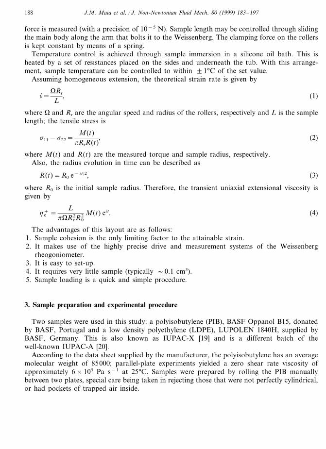
force is measured (with a precision of 10−5 N). Sample length may be controlled through slidingthe main body along the arm that bolts it to the Weissenberg. The clamping force on the rollersis kept constant by means of a spring.
Temperature control is achieved through sample immersion in a silicone oil bath. This isheated by a set of resistances placed on the sides and underneath the tub. With this arrange-ment, sample temperature can be controlled to within 91°C of the set value.
Assuming homogeneous extension, the theoretical strain rate is given by
o; =VRr
L, (1)
where V and Rr are the angular speed and radius of the rollers, respectively and L is the samplelength; the tensile stress is
s11−s22=M(t)
pRrR(t), (2)
where M(t) and R(t) are the measured torque and sample radius, respectively.Also, the radius evolution in time can be described as
R(t)=R0 e−o; t/2, (3)
where R0 is the initial sample radius. Therefore, the transient uniaxial extensional viscosity isgiven by
h e+ =
LpVR r
2R02 M(t) eo; t. (4)
The advantages of this layout are as follows:1. Sample cohesion is the only limiting factor to the attainable strain.2. It makes use of the highly precise drive and measurement systems of the Weissenberg
rheogoniometer.3. It is easy to set-up.4. It requires very little sample (typically �0.1 cm3).5. Sample loading is a quick and simple procedure.
3. Sample preparation and experimental procedure
Two samples were used in this study: a polyisobutylene (PIB), BASF Oppanol B15, donatedby BASF, Portugal and a low density polyethylene (LDPE), LUPOLEN 1840H, supplied byBASF, Germany. This is also known as IUPAC-X [19] and is a different batch of thewell-known IUPAC-A [20].
According to the data sheet supplied by the manufacturer, the polyisobutylene has an averagemolecular weight of 85000; parallel-plate experiments yielded a zero shear rate viscosity ofapproximately 6×10⁵ Pa s−1 at 25°C. Samples were prepared by rolling the PIB manuallybetween two plates, special care being taken in rejecting those that were not perfectly cylindrical,or had pockets of trapped air inside.

J.M. Maia et al. / J. Non-Newtonian Fluid Mech. 80 (1999) 183–197 189
LDPE samples were prepared by extruding out of a capillary rheometer at 200°C, using 2 mmdies. The extrudate was collected into a water bath in order to accelerate the cooling and, hence,reduce the risk of the material losing symmetry. Extrusion conditions were kept in such a wayas to avoid the presence of instabilities. Zero shear rate viscosity was measured at 7×10⁴ Pa s−1
at 150°C and 1.4×10⁵ Pa s−1 at 130°C. Typical sample radii ranged between 2 and 4.5 mm, forboth materials; this corresponds to sample length to diameter ratios between 10 and 20, in orderto keep in line with the suggestions of Vinogradov et al. [11].
Experiments were performed at room temperature (25°C) for PIB and at 130 and 150°C forLDPE. The silicone oil was chosen so that its density roughly matched that of the LDPE andits viscosity is 0.973 Pa s−1 at 25°C.
As mentioned earlier, sample loading is of extreme importance and, while the procedure initself is straightforward, special care had to be taken in the process. PIB samples were loadedonto the rheometer and the rollers were set to rotate, at a low angular velocity, in order toremove any existing sagging. When a non-zero torque is read, the rollers are stopped and thesample is allowed to relax. Only then is the experiment started. When testing LDPE samples, bythe time the test temperature was reached, any tensions originating from the extrusion processhad already relaxed, i.e. the measured torque was zero, and the experiments could be startedimmediately.
One other feature to be careful with is the actual clamping of the sample to the fixture on thetop plate of the Weissenberg. The clamping force must not be too high or the sample may becrushed.
4. Results and discussion
4.1. Concept 6alidation
Transient extensional viscosity results, for IUPAC-X, are presented in Fig. 2, for measure-ments performed on the MRR (in open symbols), at 150°C. These are compared to the resultsof Rauschenberger [21] (full lines), which were obtained using the Rheometrics RME, andPadmanabhan et al. [18] (dotted lines), which were obtained using the fibre-windup technique.The former are essentially coincident with those originally reported by Munstedt and Laun forIUPAC-A [19].
It is apparent from Fig. 2 that the agreement between the MRR and the other techniques isvery good, considering how difficult it has been to replicate extensional viscosity measurementsusing different methods [22,23]. In fact, the MRR shows not only the correct departure from thecreep curve, but also seems to be able to capture the onset of the inflexion in the transientviscosity. In this respect, fibre-windup is in disagreement with the other methods, since it showsan unbounded behaviour in the transient viscosity that the authors [18] attribute to problems inthe sample preparation technique.
All three techniques appear to yield the correct limiting behaviour of h e+ =3h0 for low strain
rates, in the sense that the initial parts of the start-up curves form an envelope which, whenextrapolated to very long times, tends to 3h0. None of the techniques are able to achieve highenough strains to assess about the existence or not of a steady state in elongation for IUPAC-Xat this temperature.

J.M. Maia et al. / J. Non-Newtonian Fluid Mech. 80 (1999) 183–197190
Fig. 5. Transient uniaxial extensional viscosity results for IUPAC-X at 130°C. Strain rates (s−1) are as shown.
Result reproducibility was always good on the MRR, as can be seen in Fig. 3, where theresults for four different experiments at a strain rate of 0.046 s−1 are presented. The generalagreement is always good (within 10%) except for the longest times where sample cross-sectionbecomes very small (in this region values of transient viscosity may change up to 30%). All theexperiments reported in this work were repeated at least three times, the results shown being theaverage values of all the experiments for a given test condition.
The effective strain rates were obtained by experimental fitting of the evolution in time ofsample radius, as shown in Fig. 4 for IUPAC-X at 150°C. This was achieved by resorting tovideo footage and fitting Eq. (3) to the experimental data This method yielded effective strainrates different by up to 40% to those expected theoretically. Since this assumption is presumablyvalid for many of the existing extensional rheometers, it is recommended that, wheneverpossible, the determination of strain rates is carried out experimentally instead of theoretically.From Fig. 4 it is apparent that one is able to accurately determine strain rates from theexperimentally evaluated radius evolution.
Experiments were also conducted on IUPAC-X at 130°C (Fig. 5); the results are in-line withwhat would be expected, showing higher values of transient extensional viscosity for similarstrain rates when compared to the results obtained at 150°C. The low-strain-rate limit conditionof h e
+ =3h0 seems, as before, to be obeyed.MRR results of h e
+ for PIB are presented in Fig. 6 (represented by symbols). These arecompared with those of Padmanabhan et al. [17] (full lines). Due to current rheometerlimitations in data acquisition speed, the maximum achievable strain rate for PIB was 0.21 s−1,which is lower than most of those obtained by fibre wind-up. This posed some problems in

J.M. Maia et al. / J. Non-Newtonian Fluid Mech. 80 (1999) 183–197 191
confronting results from both techniques, although, for the range of strain rates wherecomparison was possible, the measured values of h e
+ are similar. The limit low-strain-ratebehaviour is, again, obeyed by the MRR.
Stretch uniformity was checked visually in all experiments (again resorting to video footage)and does not seem to constitute a problem with the MRR. A typical example is shown in Fig.7 which represents the evolution of sample cross-section in time (in this case for PIB at a strainrate of 0.021 s−1). It is apparent that the cross-section remains uniform throughout theexperiment.
The possibility of sample slip at the rollers was also investigated. A typical measured torquecurve is shown in Fig. 8 (PIB, at o; =3.6×10⁻³ s−1). When slip starts occurring, the rate ofchange of the torque is expected to decrease (this corresponds to a lower ‘effective’ strain rate).Visual observation of the evolution of sample radius also supports this assumption. When themeasured torque becomes constant, so does the cross-section (in some cases, the sample does notfail at all during the experiment). Therefore, when a change in slope in the torque is detected,it is taken as an indication of the onset of slip at the rollers and all further data is rejected.
An interesting feature observed for PIB was the fact that the Hencky strain corresponding tothe maximum in h e
+, oviscmax, seems to vary linearly with strain rate, as presented in Fig. 9. Thereason for this behaviour is unclear, possible that the higher the mechanical stimulus, i.e. thestrain rate, the slower the response of the molecules orienting towards the flow, i.e. the higherthe initial ‘overshoot’.
Fig. 6. Transient uniaxial extensional viscosity results for PIB at 25°C. Open symbols, MRR; full lines, fibre wind-up.Strain rates (s−1) are as shown.

J.M. Maia et al. / J. Non-Newtonian Fluid Mech. 80 (1999) 183–197192
Fig. 7. Sample cross-section evolution in time. PIB at 25°C. o; =0.012 s−1. Photos taken after: top, 0 s; centre, 80 s;bottom, 120 s. Experiment started at 17.0 s tape time.
All of the experiments were carried out using the second most sensitive measurement setting(out of four available) in the laboratory. This represents an extra advantage in using the MRR,since it means that the available measurement possibilities more than encompass those rangesneeded for typical materials such as these.

J.M. Maia et al. / J. Non-Newtonian Fluid Mech. 80 (1999) 183–197 193
4.2. Study of rupture conditions
When studying the extensional flow of polymer melts, it is extremely important to try tominimise the errors induced by rheometer design. Another feature that is crucial to this type ofstudy is the set of conditions under which the polymer looses cohesion. In fact, where in shearone can continue a given experiment ad infinitum, that is not true in extension, due to eventualsample rupture.
According to several authors [24–26], one of the major factors influencing the rupture ofpolymer melts is the transition of the polymer from the fluid to the rubbery state, at high enoughstrain rates.
However, before the analysis is carried out, it is necessary to clarify the meaning of the wordrupture adopted here; by rupture, physical rupture is meant, as opposed to other types of failuresuch as necking of the sample. In turn, this means that any experiments for which necking orslip were detected (for long times of stretching) were discarded for this particular study.
When studying the dependence of the Hencky strain at rupture on strain rate, Malkin andPetrie [26] distinguish four zones, which correspond to as many different types of behaviour.This is explained in Fig. 1 of the above reference. Malkin and Petrie split extensional flow intoviscous and elastic flow components. The former corresponds to a flow regime where largeirreversible extensional deformations are possible before rupture, whereas the latter does so toa flow regime where the deformation is large (but finite) and reversible. In both cases the ruptureis ductile.
Fig. 8. Measured torque evolution in time. PIB at 25°C. o; =0.0036 s−1.

J.M. Maia et al. / J. Non-Newtonian Fluid Mech. 80 (1999) 183–197194
Fig. 9. Variation of oviscmax with strain rate for PIB at 25°C.
Zone I (termed flow zone) corresponds to low strain rates. In this region, steady elonga-tional flow is possible because extension due to real viscous flow can continue indefinitely(although, eventually, rupture will occur due to surface tension). In Zone II (termed transi-tion zone), the superposition of elastic and viscous elongational flows occurs. Steady flowappears impossible to obtain due to sample rupture. In this region, a sharp drop is observedfor the limiting strain as the strain rate is increased. In zone III (termed rubbery zone), thedeformation is almost entirely elastic and there exists virtually no viscous flow. Again, steadystate is not achievable. The limiting strain increases with strain rate up to a maximum, atwhich point the strain rate is high enough for the transition to the glass like zone (Zone IV)to occur, with the consequent decrease in attainable strain with strain rate (in this region,rupture is brittle).
Malkin and Petrie also claim that the minimum in attainable strain occurs in the transitionregion from Zone II to Zone III and ranges from 1 to 2.
Although the above analysis was developed for monodisperse (or near enough) systems, itworks for the polydisperse systems studied in this paper and helps to shed some light onother existing results.
Rupture experiments were carried out as part of the already described more general experi-ments, the rupture being visualised by resorting to video footage. Only the experiments forwhich no slip was observed were taken into account, an average of the Hencky strain atrupture being taken for each strain rate.

J.M. Maia et al. / J. Non-Newtonian Fluid Mech. 80 (1999) 183–197 195
The results for IUPAC-X are shown in Fig. 10, where a simple scaling of the strain rate(the usual time-temperature superposition principle works for these flows [26]) allows resultsat different temperatures to be analysed together. It seems that MRR experiments spannedall of the zones, except that corresponding to steady flow. This means that if one wants toachieve steady state for this polymer (which has been used, to some extent, as a ‘standard’one), one needs to go into the extremely low strain rates region. This is probably theexplanation for the fact that steady state was never reported for LDPE. In practical terms, itis probably pertinent to ask whether or not it is worth it trying to achieve steady state forLDPE. The answer is (probably) negative. The strain rates one would need to maintain, inorder to obtain such a flow, are so low that the practical usefulness, i.e. from the industrialpoint of view, would be extremely limited. As a final remark on these results, it is worthnoting that the minimum predicted value for o seems to lie between l and 2, which is in linewith the forecast of Malkin and Petrie.
For PIB, all of the experiments were performed in the region corresponding to elastic flow(Fig. 11) which is not surprising, since PIB is elastomeric at room temperature. The maxi-mum attainable strains are lower than for IUPAC-X presumably due to the almost completeabsence of viscous, irreversible deformation.
Fig. 10. Study of rupture conditions. IUPAC-X at 150°C reference temperature. Closed symbols, experimental; fullline, best fit of model of Malkin and Petrie [26].

J.M. Maia et al. / J. Non-Newtonian Fluid Mech. 80 (1999) 183–197196
Fig. 11. Study of rupture conditions. PIB at 25°C. Closed symbols, experimental; full line, best fit of model of Malkinand Petrie [26].
5. Conclusions
The MRR is an adaptation of a Weissenberg Rheogoniometer in order to measure transientuniaxial extensional viscosity of polymer melts. This apparatus has several positive features,including the fact that it makes use of the extremely precise driving and measuring systems ofthe rheogoniometer, it is easy to set-up, it requires a small quantity of sample and stretching ishomogeneous. This makes sample cohesion the only practical limit to measurements (in this firstbasic version, Hencky strains in excess of 5 were achieved).
Experiments were carried out for two melts, at several temperatures, and the results showedthat the MRR is capable of replicating quantitatively those obtained using such well establishedtechniques as fibre-windup and those of the Meissner type.
Studies of sample rupture were also carried out, since this poses one of the greatest limitationsto experimentally achievable strains. These showed that, for IUPAC-X, it will be very difficult(if not nearly impossible) to achieve steady state. The same applies to PIB, since the deformationis almost entirely elastic.
Acknowledgements
The authors are very grateful to BASF, Portugal, Dr H.M. Laun from BASF, Germany forkindly supplying the materials used in this work and Dr V. Rauschenberger for performing themeasurements on the RME.

J.M. Maia et al. / J. Non-Newtonian Fluid Mech. 80 (1999) 183–197 197
References
[1] M. Rides, NPL Report CMMT(A)38, Industrial need for extensional viscoelasticity measurements, September1996 (submitted for approval).
[2] J.M. Maia, D.M. Binding, Accepted for publication by Rheol. Acta, 1997.[3] J. Meissner, Rheol. Acta 8 (1969) 78–88.[4] J. Meissner, Trans. Soc. Rheol. 16 (1972) 405–420.[5] C.S. Petrie, Rheol. Acta 34 (1995) 12–26.[6] J.M. Dealy, J. Non-Newtonian Fluid Mech. 4 (1978) 9–21.[7] M. Rides, C.R.G. Allen, S. Chakravorty, NPL Report CMMT(A) 44, Review of extensional viscoelasticity
measurement techniques for polymer melts, 1996.[8] R.K. Gupta, T. Sridhar, Elongational Rheometers, in: A.A. Collyer, D.W. Clegg (Eds.), Rheological measure-
ment, Elsevier Applied Science, Barking, UK, 1988.[9] C.J.S. Petrie, Elongational Flows, Pitman, London, 1979.
[10] J. Meissner, J. Hostettler, Rheol. Acta 31 (1994) 1–21.[11] G.V. Vinogradov, V.D. Fikhman, B.V. Radushkevich, A. Ya. Malkin, J. Polym. Sci. A2 (8) (1970) 657–678.[12] R. Hingman, B.L. Marczincke, J. Rheol. 38 (1994) 573–587.[13] L.A. Utracki, M.R. Kamal, N.M. Al-Bastaki, Conference Proc., ANTEC 1984, pp. 417–420.[14] B. Schlund, L.A. Utracki, Polym. Eng. Sci. 27 (1987) 1523–1529.[15] H.M. Laun, H. Munstedt, Rheol. Acta 17 (1978) 415–425.[16] C.W. Macosko, J.M. Lornston, SPE Tech. Papers 19 (1973) 461–467.[17] R.W. Connely, L.J. Garfield, G.H. Pearson, J. Rheol. 23 (1979) 651–662.[18] M. Padmanabhan, L.J. Kasehagen, C.W. Macosko, J. Rheol. 40 (1996) 473–481.[19] H. Munstedt, H.M. Laun, Rheol. Acta 18 (1979) 492–504.[20] J. Meissner, Pure Appl. Chem. 42 (1975) 553–612.[21] V. Rauschenberger, data sheet supplied with the material.[22] N.E. Hudson, T.E.R. Jones, J. Non-Newtonian Fluid Mech. 46 (1993) 69–88.[23] D.F. James, K. Walters, A critical appraisal of available methods for the measurement of extensional properties
of mobile systems, in: A.A. Collyer (Ed.), Techniques in Rheological Measurements, Chapman and Hall,London, 1993.
[24] G.V. Vinogradov, A. Ya. Malkin, V.V. Volosevitch, Appl. Polym. Symp. 27 (1975) 47–59.[25] G.V. Vinogradov, A. Ya. Malkin, V.V. Volosevitch, V.P. Shatalov, Y.P. Yudin, J. Polym. Sci. Polym. Phys. 13
(1975) 1721–1735.[26] A. Ya. Malkin, C.J.S. Petrie, J. Rheol. 41 (1997) 1–25.
.
Related Documents