Measuring Phase Difference Dr. Len Trombetta 1 ECE 2100

Measuring Phase Difference Dr. Len Trombetta 1 ECE 2100.
Jan 01, 2016
Welcome message from author
This document is posted to help you gain knowledge. Please leave a comment to let me know what you think about it! Share it to your friends and learn new things together.
Transcript

Measuring Phase Difference
Dr. Len Trombetta
1
ECE 2100

The Idea…
2
This lab:- Apply a sinusoid to find frequency domain properties.- Measure phase difference between input and output.
Previous lab: - Time domain measurement of an RC time constant.- Apply a square wave to simulate the on/off action of a switch.

input outputSet Up
3
Connect the FG to your input and to the scope. Connect your output to the scope as well.
Function generator: sine wave at 3000 Hz.
R = 47 [kW]C = 0.022 [mF]

Frequency Analysis
4
+
-
+
-
Vin Vout
𝑉 𝑜𝑢𝑡=𝑉 𝑖𝑛1/ 𝑗 𝜔𝐶
𝑅+1/ 𝑗𝜔𝐶
¿𝑉 𝑖𝑛1
1+ 𝑗 𝜔𝑅𝐶
What happens to the output at very high and very low frequencies? Is there a phase change? Observe this on the scope.

Phase Difference
5
Input and output are not in phase. We want to measure the phase difference .
𝑣 𝑖𝑛=V∈sin (2𝜋 𝑓𝑡 ) 𝑣𝑜𝑢𝑡=V out sin (2𝜋 𝑓𝑡+∆𝜑 )
We cannot measure the absolute phase of either waveform - we can only measure the phase difference.

The Measurement
6
Because one full period (T) of the input (and output) sinusoids corresponds to 360 [deg], we have:
∆𝜑360
=∆ 𝑡𝑇
Dt T
You can use the vertical cursors to help with this.

The Scope Probe
7
Problem: The oscilloscope input impedance distorts the measurement of vc(t), just as a voltmeter distorts the measurement of a dc voltage. The distortion is a function of frequency.
Cscope ~ 20 [pF]
Rscope ~ 1 [MW]
Thevenin Equivalent of the oscilloscope input

The Solution…
8
We can compensate for this effect by using a “scope probe” between the circuit output and the scope.
+
-
vin
CircuitScope Probe Scope
+
-
vmeas

Analysis
9
+
-
Vout
+
-
Vmeas
Rp, Cp: scope probe resistance and capacitance
Rs, Cs: oscilloscope input resistance and capacitance
Vout: circuit output; this is what we want to measure
Vmeas: input to scope; this is what shows up on the display
Analysis
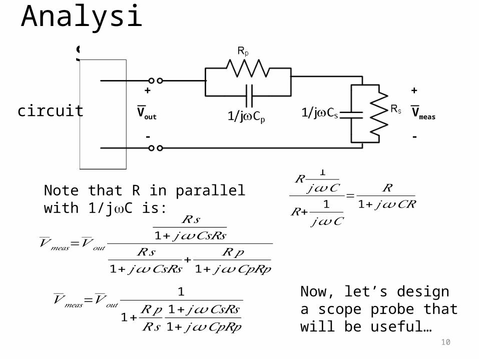
10
+
-
Vmeas
𝑅1
𝑗 𝜔𝐶
𝑅+ 1𝑗𝜔𝐶
=𝑅
1+ 𝑗𝜔𝐶𝑅Note that R in parallel with 1/jwC is:
𝑉𝑚𝑒𝑎𝑠=𝑉 𝑜𝑢𝑡
𝑅𝑠1+ 𝑗 𝜔𝐶𝑠𝑅𝑠
𝑅𝑠1+ 𝑗 𝜔𝐶𝑠𝑅𝑠
+ 𝑅𝑝1+ 𝑗𝜔𝐶𝑝𝑅𝑝
𝑉𝑚𝑒𝑎𝑠=𝑉 𝑜𝑢𝑡1
1+𝑅𝑝𝑅𝑠
1+ 𝑗 𝜔𝐶𝑠𝑅𝑠1+ 𝑗 𝜔𝐶𝑝𝑅𝑝
Now, let’s design a scope probe that will be useful…
+
-
Voutcircuit

11
If we design the probe so that CpRp = CsRs, then…
𝑉𝑚𝑒𝑎𝑠=𝑉 𝑜𝑢𝑡1
1+𝑅𝑝𝑅𝑠
If we also make Rp = 9 Rs and Cp = 1/9 Cs, then CsRs = CpRp and
𝑉𝑚𝑒𝑎𝑠=𝑉 𝑜𝑢𝑡1
10
From the last slide:
What have we accomplished?
+
-
Vmeas
+
-
Voutcircuit
𝑉𝑚𝑒𝑎𝑠=𝑉 𝑜𝑢𝑡1
1+𝑅𝑝𝑅𝑠
1+ 𝑗 𝜔𝐶𝑠𝑅𝑠1+ 𝑗 𝜔𝐶𝑝𝑅𝑝
12
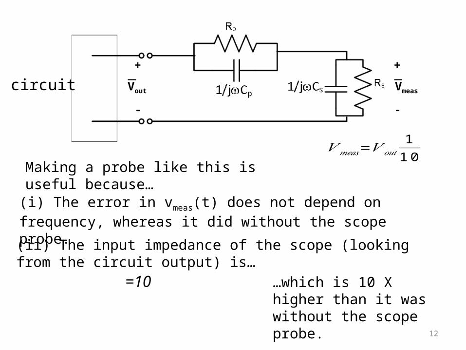
𝑉𝑚𝑒𝑎𝑠=𝑉 𝑜𝑢𝑡1
10Making a probe like this is useful because…
(i) The error in vmeas(t) does not depend on frequency, whereas it did without the scope probe.
(ii) The input impedance of the scope (looking from the circuit output) is…
=10 …which is 10 X higher than it was without the scope probe.
+
-
Vmeas
+
-
Voutcircuit

Bottom Line
13
+
-
Vout
+
-
Vmeas
We have increased the input impedance of the scope by 10X. This means less distortion in the measurement. It’s like having a voltmeter with 10X more resistance.
We have removed frequency dependence in the error, i.e., we no longer have a frequency-dependent distortion in the amplitude and phase measurements.
We have paid a price for this: our signal has been reduced by a factor of 10X. In other words, our measurement is 10X less sensitive.
Scope Probe Calibration
14
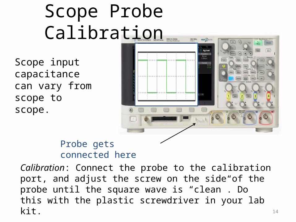
Calibration: Connect the probe to the calibration port, and adjust the screw on the side of the probe until the square wave is “clean”. Do this with the plastic screwdriver in your lab kit.
Probe gets connected here
Scope input capacitance can vary from scope to scope.

The “Probe” Setting
15
Probe button cycles among allowable probe ratios. Choose 10:1.
This changes the vertical scale indicator, so that you don’t have to do the 10X multiplication to get the right amplitude.
vertical scale indicator changes according to probe ratio. 500 mV/
Choose the input you want to adjust.
Summary
16
If the scope probe is properly adjusted, it compensates for the input impedance of the oscilloscope. It removes the frequency dependence in the measurement error, and reduces the error by increasing the input impedance of the scope by 10X. But it also reduces the sensitivity of the measurement by 10X. Usually, this is a good tradeoff.
Related Documents