Measuring Device Bisector Vernier Caliper Bachelor's thesis Mechanical Engineering and Production Technology, HAMK Autumn 2021 Alshamali Ismaeel

Welcome message from author
This document is posted to help you gain knowledge. Please leave a comment to let me know what you think about it! Share it to your friends and learn new things together.
Transcript
Measuring Device
Bisector Vernier Caliper
Bachelor's thesis Mechanical Engineering and Production Technology, HAMK
Autumn 2021 Alshamali Ismaeel
1
ABSTRACT Mechanical Engineering and Production Technology Riihimäki Tekijä Alshamali Ismaeel Year 2021 Työn Measuring Device, Bisector Vernier Caliper
Ohjaajat Timo Kärppä ja Jaakko Vasko
TIIVISTELMÄ Opinnäytetyön aiheena on mekaaninen mittalaite, joka on merkityksellinen teollisissa työpajoissa ja muissa. Saavuttaakseen kustannustehokkaan ja nopean mittauksen laboratoriossa, oli kehitettävä mittalaite Vernier Calliper Bisector. Tämä mittalaite korvaa kalliit ja monimutkaiset menetelmät pyörähdyskappaleiden keskipisteiden määrittämiseen sorveissa. Laite tarjoaa erittäin hyvän tarkkuuden ja korkean suorituskyvyn. Tämän työn päätarkoitus on kehittää standardoitu Vernier-asteikko, joka mahdollistaa pyörähdyskappaleiden ja symmetristen kartiomaisten akseleiden keskipisteet, sekä määrittämään etäisyydet kartioiden välillä sekä kartioiden kulmat. Mittalaite myös vähentää kustannuksia yhdistämällä kaksi laitetta: suorakulman ja työntömitan, jolloin käyttäjät voivat hyötyä kahdesta laitteesta yhdessä. Laite koostuu voimansiirrosta, kahdesta telineestä ja hammaspyörästä; kiinteän, liikkuvan ja puolikkaan leuan lisäksi. Tämän projektin asiakaana ovat kaikki, jotka ovat kiinnostuneita valmistuksesta, kuten tehtaat, yritykset, teolliset työpajat, laboratoriot, yliopistot ja jopa harrastajat. Haluan kiittää lehtoreita Timo Kärppä ja Jaakko Vasko kandidaatintutkimukseni valvonnasta. Kiitän myös ystäviäni, jotka auttoivat minua tekemään tämän tutkimuksen. Avainsanat: solidworks, creo, mekaaniset mittaustyökalut, vernier caliper, suorakulmainen viivain, bisector vernier caliper ja bisector leuka.
2
ABSTRACT Mechanical Engineering and Production Technology Riihimäki
Author Alshamali Ismaeel Year 2021 Subject Measuring Device, Bisector Vernier Caliper Supervisor(s) Timo Kärppä ja Jaakko Vasko ABSTRACT
This final thesis is about a mechanical measuring device that demonstrates its importance in industrial workshops and other engineering venues. It has also been developed into one of the most important mechanical measurement devices in an industrial workshop. Vernier Calliper Bisector was designed to get a cost-efficient and high-speed measurement. device for a laboratory. There is no need with this device to use an expensive and complex turning machine as measurement tools determine circular centres, provide very good accuracy and high-performance measurement methods. The main purpose of this device was to develop the ordinary Vernier calliper to be able to measure a circular centre and symmetrical conical axes as well as to find out distances between cones, as well as the possibility to find the head angle of a cone and cone a stem. The device consists of a transmission, two racks and pinions, a fixed jaw, a movable jaw and a bisector jaw. Any party interested in manufacturing, can be considered as a potential customer for the product produced in this project, such as factories, companies, industrial workshops, laboratories, universities, and even hobbyists. The used methods on this thesis were comparing the aspects and functions of measurement devices specifically traditional a vernier caliper and marker the vernier caliper beside defining their components and mechanisms.
3
The main result of this study was merging traditional vernier caliper with the marker vernier caliper to become a bisector vernier caliper which could solve technical problems in a workshop and save time money and effort.
Key words bisector jaw, bisector vernier calliper, creo lib, marker vernier calliper, mechanical measuring tools, solidworks. Pages 44 pages including appendices 6 pages, and project as part / assembly
4
Contents: 1.INTRODUCTION............................................................................................................6
2. SIGINFICANCE OF MEASURING DEVICES …....................................................................7
2.1 Measurement Tools …..........................................................................................7
2.2 Mechanical Measuring Tools ….............................................................................7
2.3 Examples and Use of Mechanical Measuring Tools ….......................................... 7
3. BASIC VERNIER CALIPER …...........................................................................................10
3.1 History of Vernier.…............................................................................................10
3.2 Components of Vernier Caliper ….......................................................................11
3.3 Physics behind Vernier Caliper …........................................................................11
4. GEAR TOOTH OF VERNIER CALIPER …..........................................................................14
4.1 Measurement Method with Gear Tooth Vernier ….............................................14
4.2 Reference, Gear Analysis Method …...................................................................16
4.3 Calculation Formula for Rack Shift Coefficient ….................................................18
5. MICROMETER …..........................................................................................................19
5.1 Components of Micrometer ...............................................................................19
5.2 Reading the Scale ….............................................................................................21
5.2.1 Micrometer with Standard Scale ….............................................................21
5.2.2 Micrometer with Vernier Scale..…..............................................................22
5.3 Measurement Error Depending on Attitude and Supporting Point …...................22
5.4 Micrometer with Vernier …..................................................................................23
5.5 Formula of Micrometer …....................................................................................24
6. SURFACE TESTER / ROUGHNESS TESTER …..................................................................25
6.1 Measuring Roughness ….....................................................................................25
6.2 Roughness as a Concept …..................................................................................26
6.3 Measuring Line, Length, Shape, Offset, and Curve .............................................26
6.4 Use of Surface Roughness Tester ….....................................................................26
7. BISECTOR VERNIER CALIPER …....................................................................................28
7.1 Principle of Bisector Vernier Caliper …................................................................30
7.2 Components of Bisector Vernier Caliper ............................................................31
7.2.1 Ruler ….....................................................................................................31
7.2.2 Rack …......................................................................................................32
5
7.2.3 Moving Jaw …...........................................................................................32
7.2.4 Bisector Jaw …..........................................................................................33
7.2.5 Transmission Gear …................................................................................32
7.3 Summary of Components ..................................................................................34
7.4 Bisector Vernier Caliper and its Industrial Usage …............................................34
7.4.1 To Make Parallel Axis …............................................................................35
7.4.2 Symmetry Field ….....................................................................................36
7.4.3 Centralized Perforation to Bar or Sheet ….......…......................................37
7.4.4 Creating an Organized Perforation in a Round Pieces …..........................37
7.4.5 To Finding Symmetrical Tolerance ….......................................................38
7.4.6 To Finding Centre of any Circle ….............................................................38
7.4.7 Measuring the Angle of Head of Cone ……...............................................39
8. CONCLUSION …...........................................................................................................40
References ……….............................................................................................................41
Images Links……………………………………………………………………………………………………………….43
6
1. INTRODUCTION
The goal of this development project of a measuring device (Vernier) was to be able to draw circles’ centers and symmetrical lines on parts.
Measuring tools are devices to measure a physical quantity. In the physical sciences, quality assurance and engineering measurements are the activities of obtaining and comparing physical quantities of real-world objects and events. Established standard objects and events are used as units, and the process of measurement gives a number relating the item under study and the referenced unit of measurement. Measuring instruments, and formal test methods which define the instrument's use, and how these relations of numbers are obtained. All measuring tools may contain varying degrees of error and measurement uncertainty. These tools may range from simple objects such as Rulers and Caliper to electron microscopes and particle accelerators. The project topic here was about mechanical measuring device that would is very important in the industrial field and in other fields at many levels, for example, as to cost, speed and measuring accuracy. Using vernier caliper bisector allows us to determine circular centers and to provide a very good accuracy beside being a high-performance measurement method. It was important in this project to find out the measure circular centers and symmetrical conical axes without needing to use expensive devices such as turning a machine and at the same time achieve high accuracy in measurement. In the first stage I studied many measuring devices and how they worked, especially those related to the engineering field of various shapes, sizes, and their efficiencies. At the second stage and after same background research, I identified the problem areas based on all the data that I had concluded through previous research. At the third stage, I designed the device as a separate part, then I assembled it through the SolidWorks software so that I could examine it and use it through the program by default. At this stage, the results were very positive, as the device showed high accuracy in measurement in addition to simplicity of use. In the fourth stage, I printed the device by 3D printers, to convert it to a real model that could be examined. In the fifth stage, we sent the printed model to engineering workshops for testing and evaluating it. After evaluation, and first impressions were very positive. In the sixth stage, the device was manufactured by CNC machines, where the metal available in the factory at that time was steel. In the seventh stage, the device was sent to several universities, institutes and workshops for evaluation, and professors at the University of Aleppo also evaluated it after they subjected it to several tests, all of them being very successful.
7
2. SIGNIFICANCE OF MEASURING DEVICES
In this thesis, I will explain the importance of measuring devices in industrial workshops and the history of their development. Mechanical measuring devices witnessed many improvements, and they are still developing. In the seventh chapter, I developed a basic vernier caliper according to my earlier study of mechanical measuring devices. The caliper is illustrated in figure 1. Was one of the simplest and oldest mechanical measuring devices where it consisted of two movement jaws and fixing screw in the middle. Its function was limited to calculating the inner diameters and outer diameter (can and cover). This Calliper was primitive, and it was not very accurate, but it was accomplishing the tasks at that time.
2.1 Measurement Tools
Everyone uses many different measuring tools to measure quantities. Every one of us must have used a ruler, balance, and other different tools one day. Measurement tools are considered one of the important elements in science and engineering, as it is the first and essential link between the theoretical and the practical side. Without measuring instruments, we would not be able to observe different experiments or apply different designs on the ground. That is why scientists and engineers were interested in different measuring instruments to measure all the units in the universe around us. 2.2 Mechanical Measuring Tools
Mechanical measurement tools existed in humans before the existence of electrical measurement tools, and the main difference between them is that electricity and electronics are not used in the measurement process before, so different quantities are measured using them in a completely mechanical way, and mechanical measurement tools depend more on the user’s ability to measure and are subject to errors Human measurements are more likely during the measurement process, calibration errors, etc., vibrations that may affect the measurement process as well, and other errors that electrical measuring tools usually provide a solution to, and that is why electrical measurement tools are usually more accurate when used correctly than mechanical measurement tools. 2.3 Examples and Uses of Mechanical Measuring Tools
There are a lot of different shapes and length of rulers, and they are used to measure the unit of length and they are most commonly used mechanical measuring tools. We are talking about a mechanical balance that uses a spring to determine weights, not a digital balance, which is usually more accurate. Calipers are usually used to measure diameters, and there are a lot of shapes, whether to measure the inner or outer diameter as can be seen in figure 1.
8
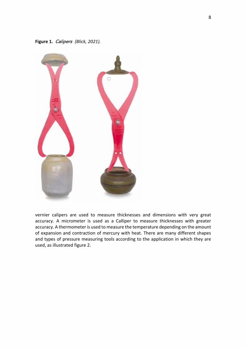
Figure 1. Calipers (Blick, 2021).
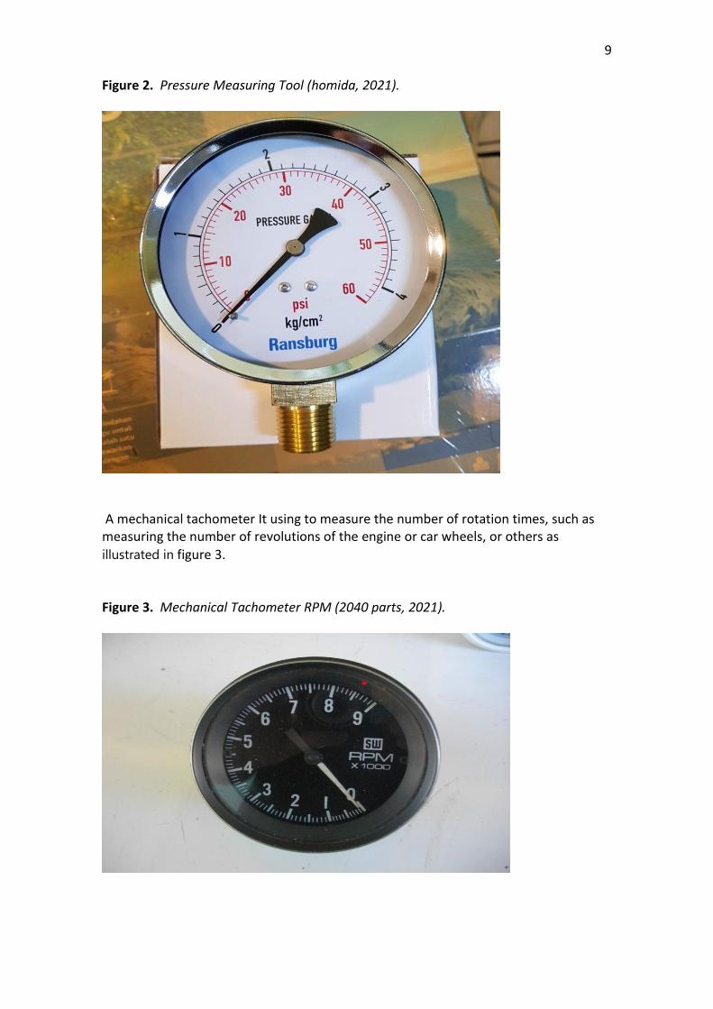
vernier calipers are used to measure thicknesses and dimensions with very great accuracy. A micrometer is used as a Calliper to measure thicknesses with greater accuracy. A thermometer is used to measure the temperature depending on the amount of expansion and contraction of mercury with heat. There are many different shapes and types of pressure measuring tools according to the application in which they are used, as illustrated figure 2.
9
Figure 2. Pressure Measuring Tool (homida, 2021).
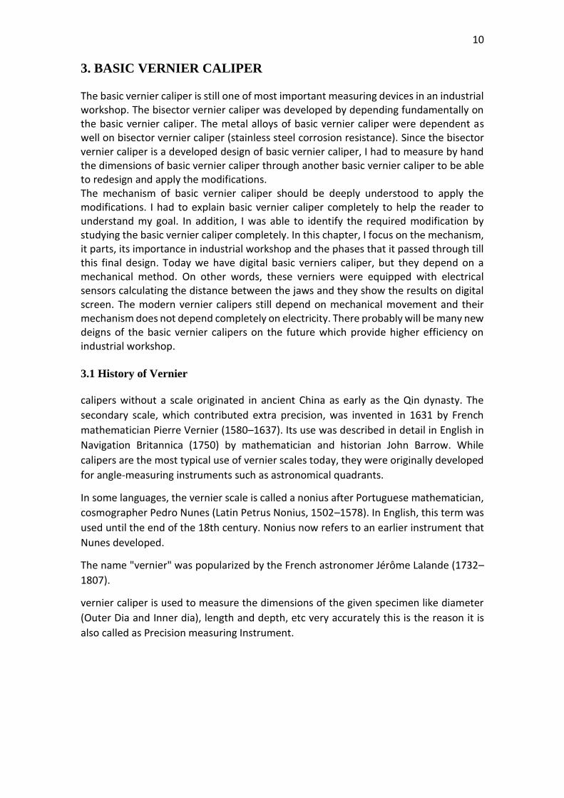
A mechanical tachometer It using to measure the number of rotation times, such as measuring the number of revolutions of the engine or car wheels, or others as
illustrated in figure 3. Figure 3. Mechanical Tachometer RPM (2040 parts, 2021).
10
3. BASIC VERNIER CALIPER
The basic vernier caliper is still one of most important measuring devices in an industrial workshop. The bisector vernier caliper was developed by depending fundamentally on the basic vernier caliper. The metal alloys of basic vernier caliper were dependent as well on bisector vernier caliper (stainless steel corrosion resistance). Since the bisector vernier caliper is a developed design of basic vernier caliper, I had to measure by hand the dimensions of basic vernier caliper through another basic vernier caliper to be able to redesign and apply the modifications. The mechanism of basic vernier caliper should be deeply understood to apply the modifications. I had to explain basic vernier caliper completely to help the reader to understand my goal. In addition, I was able to identify the required modification by studying the basic vernier caliper completely. In this chapter, I focus on the mechanism, it parts, its importance in industrial workshop and the phases that it passed through till this final design. Today we have digital basic verniers caliper, but they depend on a mechanical method. On other words, these verniers were equipped with electrical sensors calculating the distance between the jaws and they show the results on digital screen. The modern vernier calipers still depend on mechanical movement and their mechanism does not depend completely on electricity. There probably will be many new deigns of the basic vernier calipers on the future which provide higher efficiency on industrial workshop. 3.1 History of Vernier
calipers without a scale originated in ancient China as early as the Qin dynasty. The
secondary scale, which contributed extra precision, was invented in 1631 by French
mathematician Pierre Vernier (1580–1637). Its use was described in detail in English in
Navigation Britannica (1750) by mathematician and historian John Barrow. While
calipers are the most typical use of vernier scales today, they were originally developed
for angle-measuring instruments such as astronomical quadrants.
In some languages, the vernier scale is called a nonius after Portuguese mathematician,
cosmographer Pedro Nunes (Latin Petrus Nonius, 1502–1578). In English, this term was
used until the end of the 18th century. Nonius now refers to an earlier instrument that
Nunes developed.
The name "vernier" was popularized by the French astronomer Jérôme Lalande (1732–
1807).
vernier caliper is used to measure the dimensions of the given specimen like diameter
(Outer Dia and Inner dia), length and depth, etc very accurately this is the reason it is
also called as Precision measuring Instrument.
11
3.2 Components of Vernier Caliper
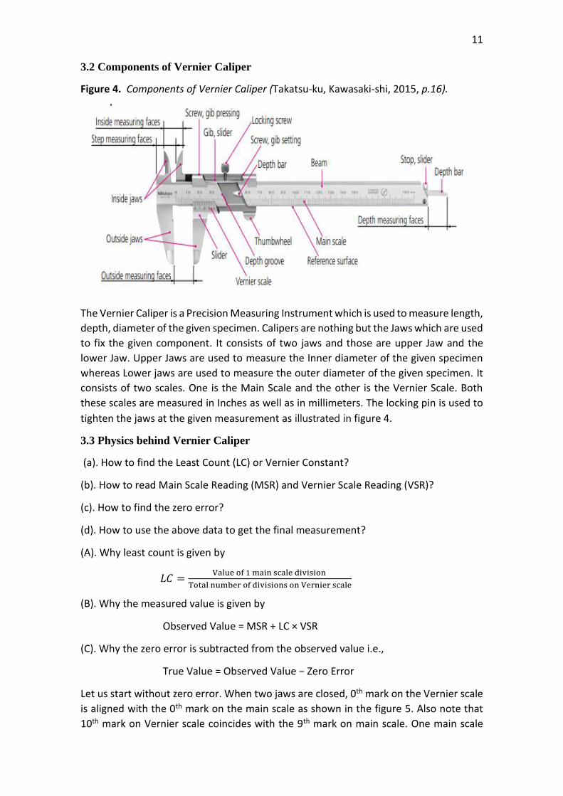
Figure 4. Components of Vernier Caliper (Takatsu-ku, Kawasaki-shi, 2015, p.16).
The Vernier Caliper is a Precision Measuring Instrument which is used to measure length,
depth, diameter of the given specimen. Calipers are nothing but the Jaws which are used
to fix the given component. It consists of two jaws and those are upper Jaw and the
lower Jaw. Upper Jaws are used to measure the Inner diameter of the given specimen
whereas Lower jaws are used to measure the outer diameter of the given specimen. It
consists of two scales. One is the Main Scale and the other is the Vernier Scale. Both
these scales are measured in Inches as well as in millimeters. The locking pin is used to
tighten the jaws at the given measurement as illustrated in figure 4.
3.3 Physics behind Vernier Caliper
(a). How to find the Least Count (LC) or Vernier Constant?
(b). How to read Main Scale Reading (MSR) and Vernier Scale Reading (VSR)?
(c). How to find the zero error?
(d). How to use the above data to get the final measurement?
(A). Why least count is given by
𝐿𝐶 =Value of 1 main scale division
Total number of divisions on Vernier scale
(B). Why the measured value is given by
Observed Value = MSR + LC × VSR
(C). Why the zero error is subtracted from the observed value i.e.,
True Value = Observed Value − Zero Error
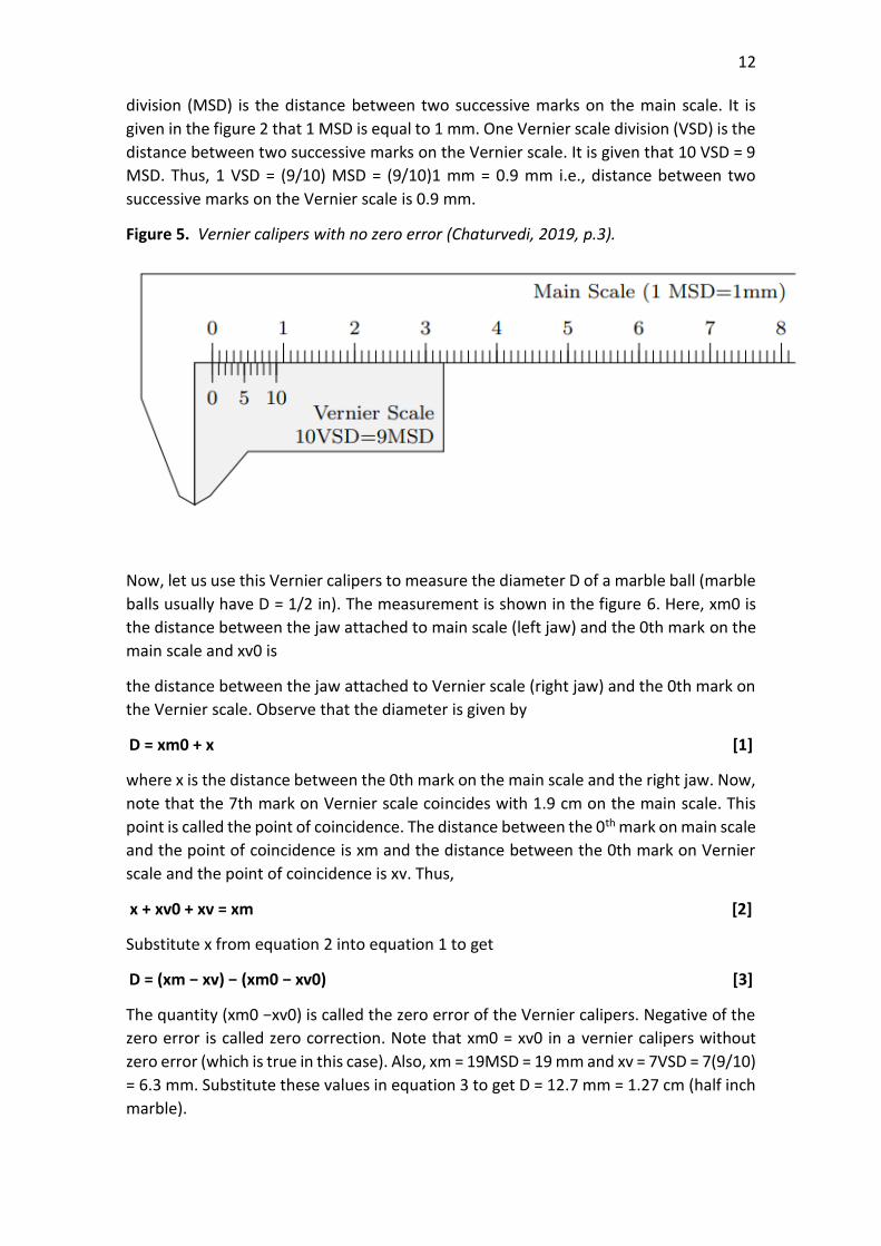
Let us start without zero error. When two jaws are closed, 0th mark on the Vernier scale
is aligned with the 0th mark on the main scale as shown in the figure 5. Also note that
10th mark on Vernier scale coincides with the 9th mark on main scale. One main scale
12
division (MSD) is the distance between two successive marks on the main scale. It is
given in the figure 2 that 1 MSD is equal to 1 mm. One Vernier scale division (VSD) is the
distance between two successive marks on the Vernier scale. It is given that 10 VSD = 9
MSD. Thus, 1 VSD = (9/10) MSD = (9/10)1 mm = 0.9 mm i.e., distance between two
successive marks on the Vernier scale is 0.9 mm.
Figure 5. Vernier calipers with no zero error (Chaturvedi, 2019, p.3).
Now, let us use this Vernier calipers to measure the diameter D of a marble ball (marble
balls usually have D = 1/2 in). The measurement is shown in the figure 6. Here, xm0 is
the distance between the jaw attached to main scale (left jaw) and the 0th mark on the
main scale and xv0 is
the distance between the jaw attached to Vernier scale (right jaw) and the 0th mark on
the Vernier scale. Observe that the diameter is given by
D = xm0 + x [1]
where x is the distance between the 0th mark on the main scale and the right jaw. Now,
note that the 7th mark on Vernier scale coincides with 1.9 cm on the main scale. This
point is called the point of coincidence. The distance between the 0th mark on main scale
and the point of coincidence is xm and the distance between the 0th mark on Vernier
scale and the point of coincidence is xv. Thus,
x + xv0 + xv = xm [2]
Substitute x from equation 2 into equation 1 to get
D = (xm − xv) − (xm0 − xv0) [3]
The quantity (xm0 −xv0) is called the zero error of the Vernier calipers. Negative of the
zero error is called zero correction. Note that xm0 = xv0 in a vernier calipers without
zero error (which is true in this case). Also, xm = 19MSD = 19 mm and xv = 7VSD = 7(9/10)
= 6.3 mm. Substitute these values in equation 3 to get D = 12.7 mm = 1.27 cm (half inch
marble).
13
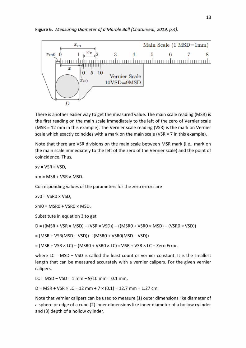
Figure 6. Measuring Diameter of a Marble Ball (Chaturvedi, 2019, p.4).
There is another easier way to get the measured value. The main scale reading (MSR) is
the first reading on the main scale immediately to the left of the zero of Vernier scale
(MSR = 12 mm in this example). The Vernier scale reading (VSR) is the mark on Vernier
scale which exactly coincides with a mark on the main scale (VSR = 7 in this example).
Note that there are VSR divisions on the main scale between MSR mark (i.e., mark on
the main scale immediately to the left of the zero of the Vernier scale) and the point of
coincidence. Thus,
xv = VSR × VSD,
xm = MSR + VSR × MSD.
Corresponding values of the parameters for the zero errors are
xv0 = VSR0 × VSD,
xm0 = MSR0 + VSR0 × MSD.
Substitute in equation 3 to get
D = ((MSR + VSR × MSD) − (VSR × VSD)) – ((MSR0 + VSR0 × MSD) − (VSR0 × VSD))
= (MSR + VSR(MSD − VSD)) − (MSR0 + VSR0(MSD − VSD))
= (MSR + VSR × LC) − (MSR0 + VSR0 × LC) =MSR + VSR × LC − Zero Error.
where LC = MSD − VSD is called the least count or vernier constant. It is the smallest
length that can be measured accurately with a vernier calipers. For the given vernier
calipers.
LC = MSD − VSD = 1 mm − 9/10 mm = 0.1 mm,
D = MSR + VSR × LC = 12 mm + 7 × (0.1) = 12.7 mm = 1.27 cm.
Note that vernier calipers can be used to measure (1) outer dimensions like diameter of
a sphere or edge of a cube (2) inner dimensions like inner diameter of a hollow cylinder
and (3) depth of a hollow cylinder.
14
4. GEAR TOOTH OF VERNIER CALIPER
There was an urgent need to invent a measuring device able to calculate the tooth deep,
tooth corner and distance between teeth while manufacturing gears. Gear tooth vernier
caliper was able successful to solve this problem. Gear tooth vernier caliper has the same
metal alloys of basic vernier caliper, but it has a completely different function. I
mentioned earlier the phases of developing the measuring the mechanical devices and
the tooth gear vernier caliper was developed from basic vernier caliper. However, it has
partially a different function that it can calculate the dimensions like the vernier caliper,
but it is specialized in manufacturing teeth. As it is a mechanical measuring device which
is the title of my thesis, I had to study this device in this chapter as well as its parts, its
mechanism and how it can be used. This device helped me in calculating the teeth of
the bisector vernier caliper (rack and gear). Formula should be achieved to make the
engagement between rack and gear. This formula depends on standards like tooth deep
and its thickness, outer diameter and reference diameter. The tooth gear of vernier
caliper can calculate these dimensions. And this the advantage that I can get. In this
chapter, I will focus on gear tooth vernier caliper and I will explain its mechanism and its
physics formula.
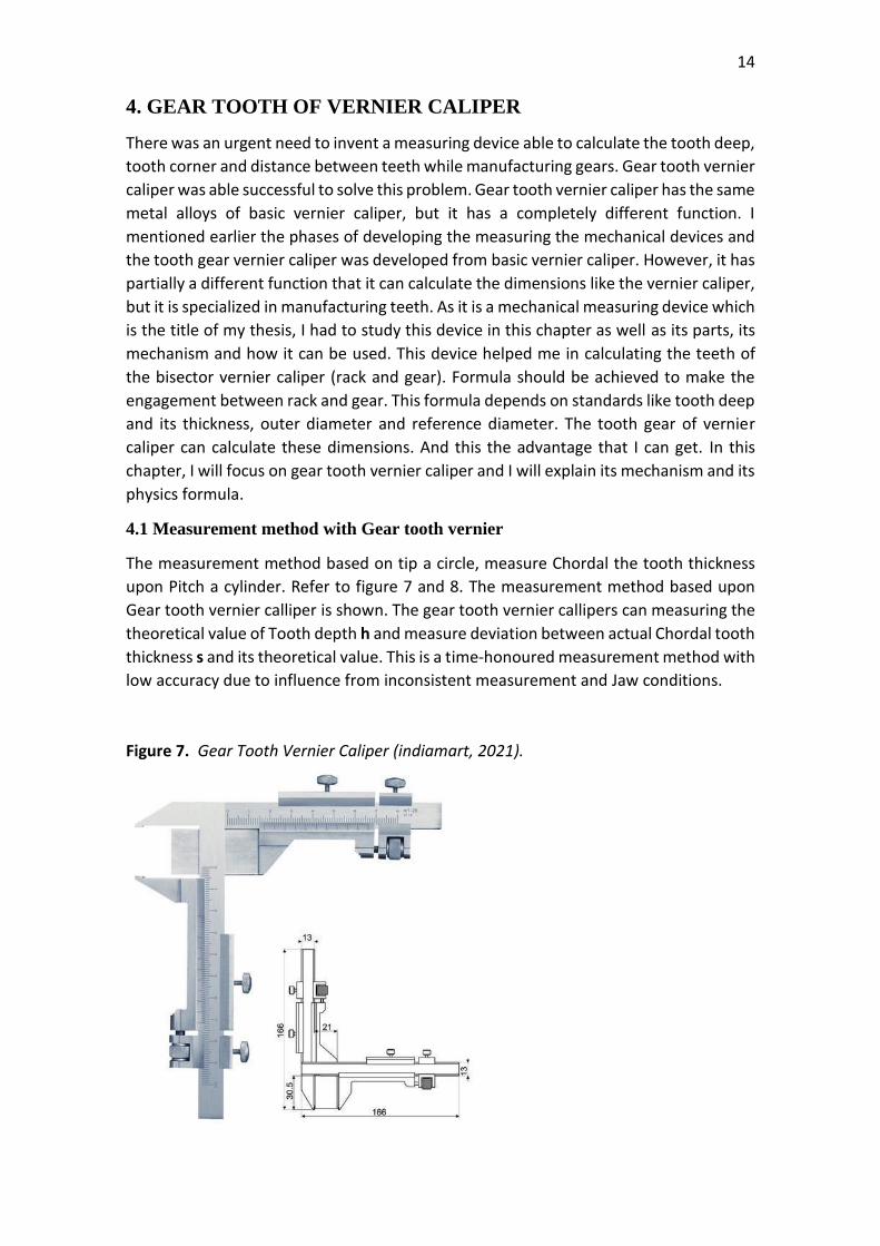
4.1 Measurement method with Gear tooth vernier
The measurement method based on tip a circle, measure Chordal the tooth thickness
upon Pitch a cylinder. Refer to figure 7 and 8. The measurement method based upon
Gear tooth vernier calliper is shown. The gear tooth vernier callipers can measuring the
theoretical value of Tooth depth h and measure deviation between actual Chordal tooth
thickness s and its theoretical value. This is a time-honoured measurement method with
low accuracy due to influence from inconsistent measurement and Jaw conditions.
Figure 7. Gear Tooth Vernier Caliper (indiamart, 2021).
15
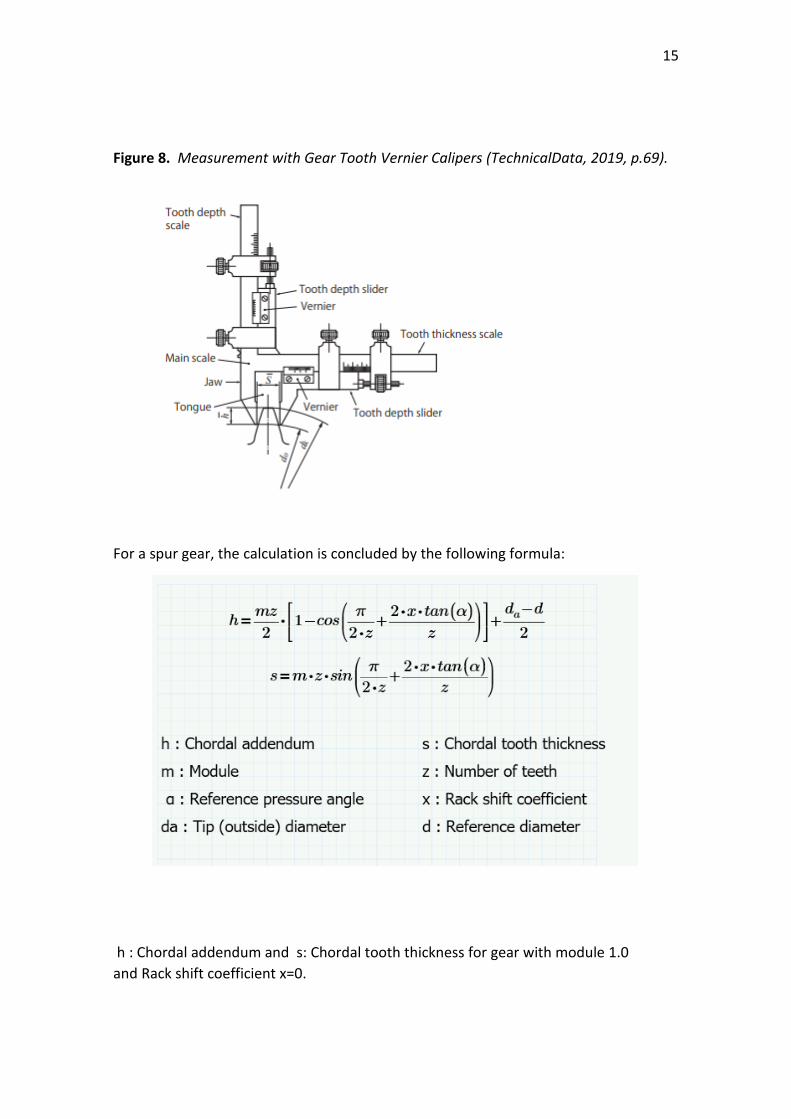
Figure 8. Measurement with Gear Tooth Vernier Calipers (TechnicalData, 2019, p.69).
For a spur gear, the calculation is concluded by the following formula:
h : Chordal addendum and s: Chordal tooth thickness for gear with module 1.0
and Rack shift coefficient x=0.
16
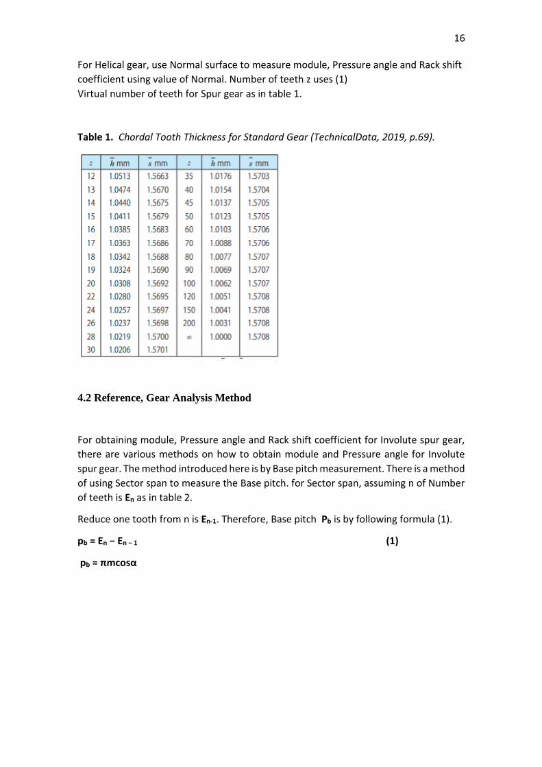
For Helical gear, use Normal surface to measure module, Pressure angle and Rack shift
coefficient using value of Normal. Number of teeth z uses (1)
Virtual number of teeth for Spur gear as in table 1.
Table 1. Chordal Tooth Thickness for Standard Gear (TechnicalData, 2019, p.69).
4.2 Reference, Gear Analysis Method
For obtaining module, Pressure angle and Rack shift coefficient for Involute spur gear,
there are various methods on how to obtain module and Pressure angle for Involute
spur gear. The method introduced here is by Base pitch measurement. There is a method
of using Sector span to measure the Base pitch. for Sector span, assuming n of Number
of teeth is En as in table 2.
Reduce one tooth from n is En-1. Therefore, Base pitch Pb is by following formula (1).
pb = En − En − 1 (1)
pb = πmcosα
17
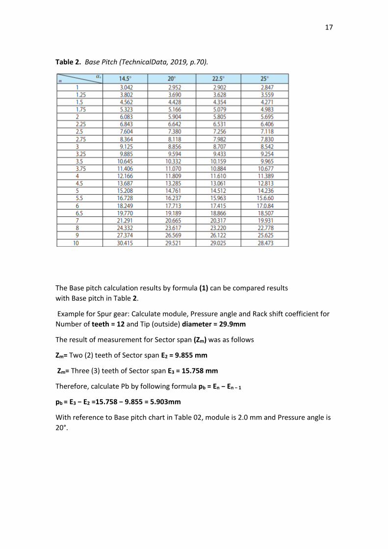
Table 2. Base Pitch (TechnicalData, 2019, p.70).
The Base pitch calculation results by formula (1) can be compared results
with Base pitch in Table 2.
Example for Spur gear: Calculate module, Pressure angle and Rack shift coefficient for
Number of teeth = 12 and Tip (outside) diameter = 29.9mm
The result of measurement for Sector span (Zm) was as follows
Zm= Two (2) teeth of Sector span E2 = 9.855 mm
Zm= Three (3) teeth of Sector span E3 = 15.758 mm
Therefore, calculate Pb by following formula pb = En − En − 1
pb = E3 − E2 =15.758 − 9.855 = 5.903mm
With reference to Base pitch chart in Table 02, module is 2.0 mm and Pressure angle is
20°.
18
4.3 Calculation Formula for Rack Shift Coefficient
Calculation for Sector span W is by following formula.
W = m*cos(α)*{π* (Zm − 0.5) + Z*inv(α)}+ 2*X*m*sin(α).
Calculating Sector span W’’ for
Standard spur gear with pressure angle 20° is by following formula:
W' = mcos(α)*{π* (Zm − 0.5) + Z*inv(α)
= m(0.01400554*z + 2*95213*z*m −1.47606)
Calculating Sector span W’” for Rack shifted spur gear with pressure angle 20° is by foll
owing formula:
W" = W'[standard]+ 2* X*m*sin(α)
W" = W'[standard]+ 0.68404*X*m (2)
[Standard] is abbreviation of Standard spur gear
From above formula (2), calculation for Rack shift coefficient x is as follow:
X = (W"_ W' ) / ( 0.68404 m) (3)
Therefore, results are W’”=9.855, W’’ = 9.193. Rack shift coefficient X is 0-.484. So
X = (9.855-9.193)/(2*0.68404) = 0.484
19
5. MICROMETER
A micrometer is considered the most accurate vernier caliper where its accuracy equals
(1/1000 mm). In this chapter, the micrometer was studied. There was an idea that the
mechanism of micrometer could be applied on the bisector vernier caliper. However,
after a making long research, I discovered that there could be a bisector micrometer
developed from the basic micrometer and it follows the same mechanism and the same
accuracy, because I have a project to develop the micrometer and it is being
accomplished currently. It is still not complete, and it could be a thesis on the future (a
bisector micrometer). But it is very hard to apply the mechanism and accuracy of a
micrometer on a bisector vernier caliper. That is why, I will try in this chapter to clarify
the mechanism of a micrometer, how it can be used, its importance, its physical features
and the phases that I went through till reaching to this bisector vernier caliper final
design. studying a micrometer device was a phase before bisector caliper designing. As
it is a mechanical measuring device which is the title of my thesis, I had to study this
device in this chapter as well as its parts, its mechanism and how it can be used.
Today micrometers are digital, but they still depend on the same mechanical
mechanism. The final improvements of a digital micrometer device were not considered
as a quantum leap, because it still depends on electric sensors calculating the distance
between the jaws of micrometer and showing the results on digital screen. On the
words, its mechanism does not depend completely on electricity. There will be probably
new designs which provide a higher efficiency on the future.
A micrometer, sometimes known as a micrometer screw gauge, is a device incorporating
a calibrated screw widely used for accurate measurement of components in mechanical
engineering and machining as well as most mechanical trades, along with other
metrological instruments such as dial, vernier, and digital calipers. Micrometers are
usually, but not always, in the form of calipers (opposing ends joined by a frame). The
spindle is a very accurately machined screw and the object to be measured is placed
between the spindle and the anvil. The spindle is moved by turning the ratchet knob or
thimble until the object to be measured is lightly touched by both the spindle and the
anvil.
5.1 Components of Micrometer
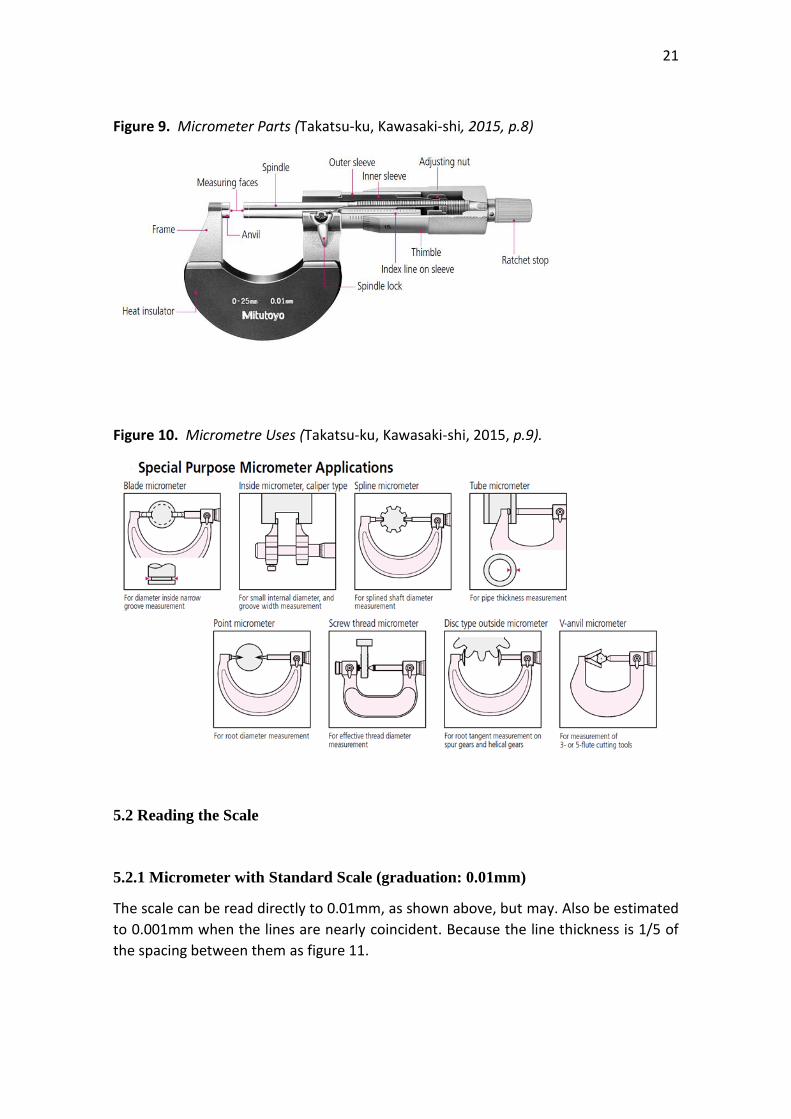
As figure 9 a micrometer is composed of:
• Frame
The C-shaped body that holds the anvil and barrel in constant relation to each other. It
is thick because it needs to minimize flexion, expansion, and contraction, which would
distort the measurement.
The frame is heavy and consequently has a high thermal mass, to prevent substantial
heating up by the holding hand/fingers. It is often covered by insulating plastic plates
which further reduce heat transference.
20
Explanation: if one holds the frame long enough so that it heats up by 10 °C, then the
increase in length of any 10 cm linear piece of steel is of magnitude 1/100 mm. For
micrometers this is their typical accuracy range.
Micrometers typically have a specified temperature at which the measurement is
correct (often 20 °C (68 °F), which is generally considered "room temperature" in a room
with HVAC). Toolrooms are generally kept at 20 °C (68 °F).
• Anvil
The shiny part that the spindle moves toward, and that the sample rests against.
• Sleeve, barrel, or stock
The stationary round component with the linear scale on it, sometimes with vernier
markings. In some instruments the scale is marked on a tight-fitting but movable
cylindrical sleeve fitting over the internal fixed barrel. This allows zeroing to be done by
slightly altering the position of the sleeve.
• Lock nut, lock-ring, or thimble lock
The knurled component (or lever) that one can tighten to hold the spindle stationary,
such as when momentarily holding a measurement.
• Screw
(Not visible) The heart of the micrometer, as explained under "Operating principles". It
is inside the barrel. This references the fact that the usual name for the device in German
is Messschraube, literally "measuring screw".
• Spindle
The shiny cylindrical component that the thimble causes to move toward the anvil as
figure 10.
• Thimble
The component that one's thumb turns. Graduated markings.
• Ratchet Stop
Device on end of handle that limits applied pressure by slipping at a calibrated torque.
21
Figure 9. Micrometer Parts (Takatsu-ku, Kawasaki-shi, 2015, p.8)
Figure 10. Micrometre Uses (Takatsu-ku, Kawasaki-shi, 2015, p.9).
5.2 Reading the Scale
5.2.1 Micrometer with Standard Scale (graduation: 0.01mm)
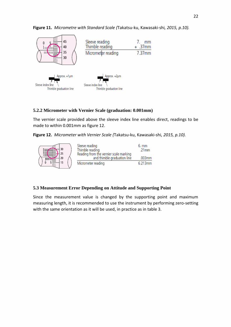
The scale can be read directly to 0.01mm, as shown above, but may. Also be estimated
to 0.001mm when the lines are nearly coincident. Because the line thickness is 1/5 of
the spacing between them as figure 11.
22
Figure 11. Micrometre with Standard Scale (Takatsu-ku, Kawasaki-shi, 2015, p.10).
5.2.2 Micrometer with Vernier Scale (graduation: 0.001mm)
The vernier scale provided above the sleeve index line enables direct, readings to be
made to within 0.001mm as figure 12.
Figure 12. Micrometer with Vernier Scale (Takatsu-ku, Kawasaki-shi, 2015, p.10).
5.3 Measurement Error Depending on Attitude and Supporting Point
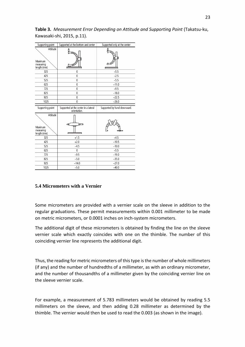
Since the measurement value is changed by the supporting point and maximum
measuring length, it is recommended to use the instrument by performing zero-setting
with the same orientation as it will be used, in practice as in table 3.
23
Table 3. Measurement Error Depending on Attitude and Supporting Point (Takatsu-ku,
Kawasaki-shi, 2015, p.11).
5.4 Micrometers with a Vernier
Some micrometers are provided with a vernier scale on the sleeve in addition to the
regular graduations. These permit measurements within 0.001 millimeter to be made
on metric micrometers, or 0.0001 inches on inch-system micrometers.
The additional digit of these micrometers is obtained by finding the line on the sleeve
vernier scale which exactly coincides with one on the thimble. The number of this
coinciding vernier line represents the additional digit.
Thus, the reading for metric micrometers of this type is the number of whole millimeters
(if any) and the number of hundredths of a millimeter, as with an ordinary micrometer,
and the number of thousandths of a millimeter given by the coinciding vernier line on
the sleeve vernier scale.
For example, a measurement of 5.783 millimeters would be obtained by reading 5.5
millimeters on the sleeve, and then adding 0.28 millimeter as determined by the
thimble. The vernier would then be used to read the 0.003 (as shown in the image).
24
Inch micrometers are read in a similar fashion.
Note: 0.01 millimeter = 0.000393 inch, and 0.002 millimeter = 0.000078 inch (78
millionths) or alternatively, 0.0001 inch = 0.00254 millimeters. Therefore, metric
micrometers provide smaller measuring increments than comparable inch unit
micrometers—the smallest graduation of an ordinary inch reading micrometer is 0.001
inch; the vernier type has graduations down to 0.0001 inch (0.00254 mm). When using
either a metric or inch micrometer, without a vernier, smaller readings than those
graduated may of course be obtained by visual interpolation between graduations.
5.5 Formula of Micrometer
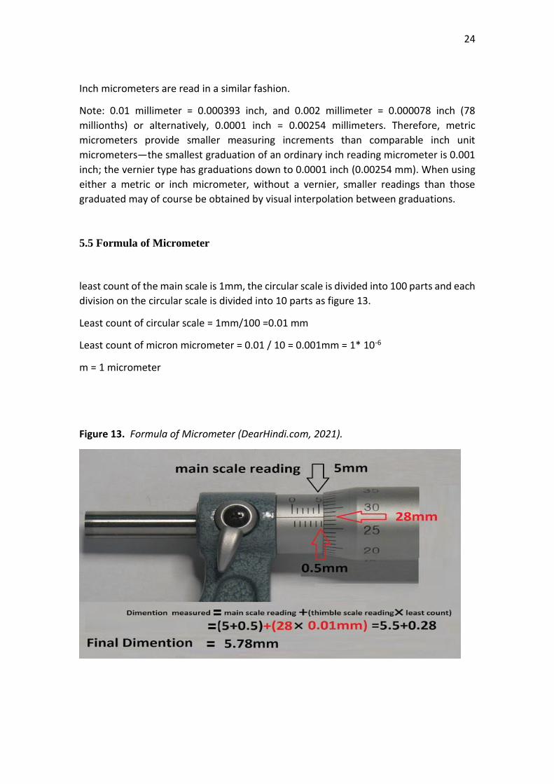
least count of the main scale is 1mm, the circular scale is divided into 100 parts and each
division on the circular scale is divided into 10 parts as figure 13.
Least count of circular scale = 1mm/100 =0.01 mm
Least count of micron micrometer = 0.01 / 10 = 0.001mm = 1* 10-6
m = 1 micrometer
Figure 13. Formula of Micrometer (DearHindi.com, 2021).
25
6. SURFACE TESTER / ROUGHNESS TESTER
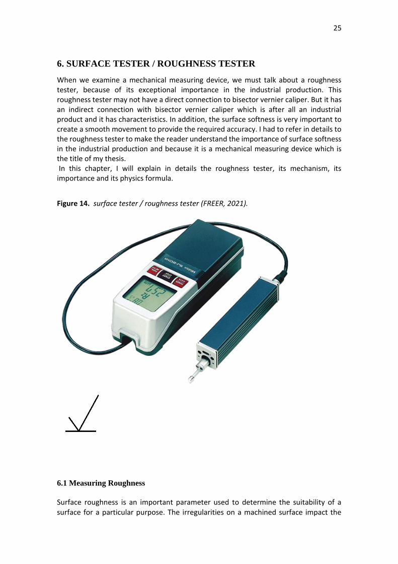
When we examine a mechanical measuring device, we must talk about a roughness tester, because of its exceptional importance in the industrial production. This roughness tester may not have a direct connection to bisector vernier caliper. But it has an indirect connection with bisector vernier caliper which is after all an industrial product and it has characteristics. In addition, the surface softness is very important to create a smooth movement to provide the required accuracy. I had to refer in details to the roughness tester to make the reader understand the importance of surface softness in the industrial production and because it is a mechanical measuring device which is the title of my thesis. In this chapter, I will explain in details the roughness tester, its mechanism, its importance and its physics formula.
Figure 14. surface tester / roughness tester (FREER, 2021).
6.1 Measuring Roughness
Surface roughness is an important parameter used to determine the suitability of a surface for a particular purpose. The irregularities on a machined surface impact the
26
quality and performance of that surface and the performance of the end product.
Rougher surfaces typically wear more quickly than smoother surfaces and are more vulnerable to corrosion and cracks, but they can also promote adhesion. A roughness tester, also referred to as roughness gauge or roughness meter, is a portable device that is used to quickly and easily measure the surface roughness (surface finish) of an object.
6.2 Roughness as a Concept
Typical roughness testers provide a linear roughness measurement, tracing a mechanical tip along a surface to measure roughness along an arbitrary line. More sophisticated versions provide an areal roughness measurement, which measures an area of the surface using non-contact methods, such as lasers, optics, interferometers,
and more, to give finer resolution and wide area measurements. For this discussion we will focus on portable roughness testers and linear roughness measurement. Roughness values are typically reported in Ra, which is the average absolute deviation
from a central line of a surface; Rq, which is the root mean square of the deviation, and
numerous other values that measure peak heights and depths of valleys. For most
applications Ra and Rq provide an adequate indication. For specially designed surfaces,
the other parameters may be more appropriate.
6.3 Measuring line lengths, shapes, offsets, and curve
Roughness testers can measure several predetermined lengths. Shorter distances are
used to measure finer surfaces, while longer lines are traced for rougher surfaces. It is
good to ask about the different options available when considering a roughness tester.
Some roughness testers have an interchangeable stylus or probe for measuring different
shapes, offsets, and curves. To measure either the inner diameter or an outer diameter.
some roughness testers are able to display the results of the surface finish in either
micro-inches or micrometres, saving you the step of having to convert it manually.
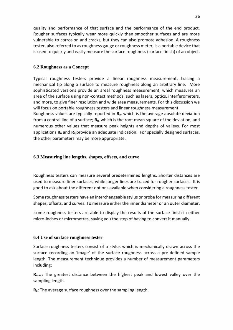
6.4 Use of surface roughness tester
Surface roughness testers consist of a stylus which is mechanically drawn across the
surface recording an 'image' of the surface roughness across a pre-defined sample
length. The measurement technique provides a number of measurement parameters
including:
Rmax: The greatest distance between the highest peak and lowest valley over the
sampling length.
Ra: The average surface roughness over the sampling length.
27
Rt: The distance between the highest peak and the lowest valley within any given
sampling length.
Rz: The average distance between the highest peak and the lowest valley over a number
of sampling lengths.
Figure 15. How We Use Roughness Tester (elcometer, 2016).
A deep study should be done about mechanical measuring devices and their uses in
industrial workshops in order to develop any mechanical measuring device.
Based on what was mentioned earlier on this research, the traditional vernier caliper
has been developed into bisector vernier caliper.
Developing Mechanical measuring devices can only be done sequentially, as a result of
the lack of accuracy or because they do not solve all industrial problems. Mechanical
measuring devices are in constant development till reaching today to digital measuring
devices, which are considered more accurate than the previous ones.
Studying mechanical measuring devices paved the way for inventing the bisector vernier
caliper. The modification that was made to the traditional vernier caliper was granted a
patent from Syria in 2010.
In the seventh chapter, the bisector vernier caliper and its mechanism were illustrated
in details. The seventh chapter of the thesis is considered as the most important part
and the link between all chapters.
28
7. BISECTOR VERNIER CALLIPER
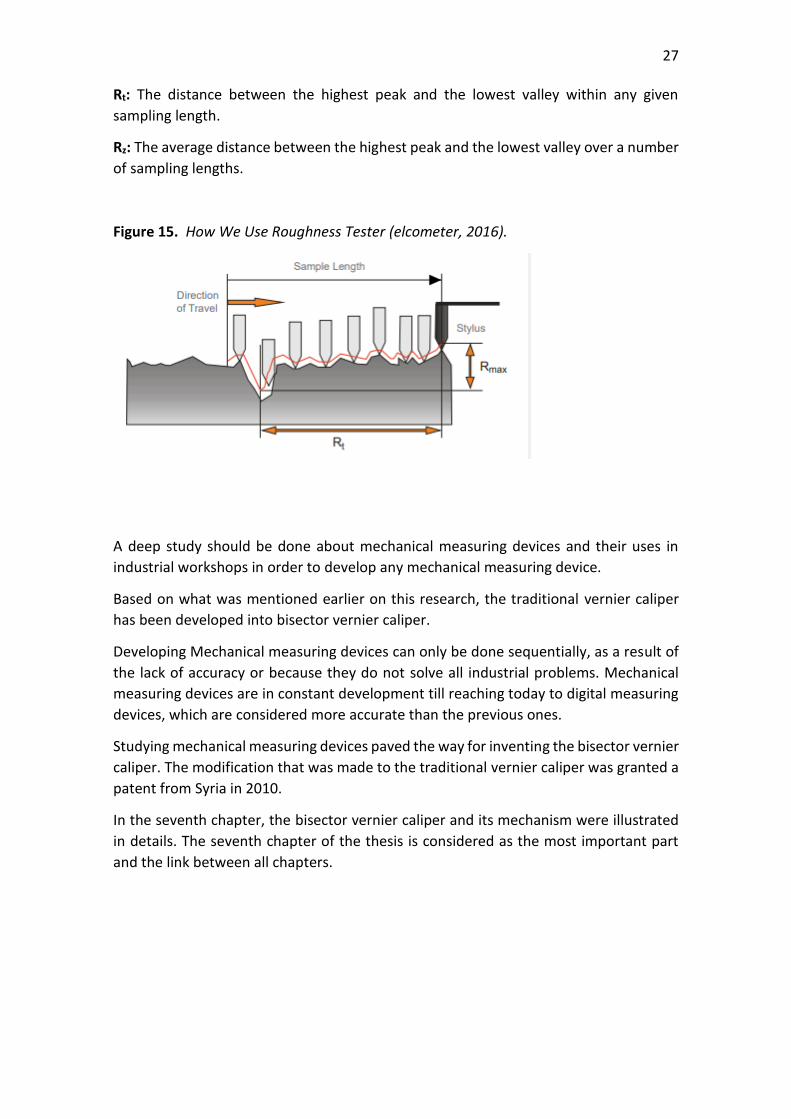
Figure 16. The bisector vernier caliper old design (2010).
In past we had two measuring device which are marker vernier caliper and basic vernier
caliper. The marker vernier caliper can draw a straight line on the metal surface that
should be holed or cut. In sheet metal workshop, marker vernier caliper is basically
needed, but in some situations the basic vernier caliper is needed as well. The bisector
vernier caliper was able to solve this problem and it performs the function of these two
devices and it can replace them.
29
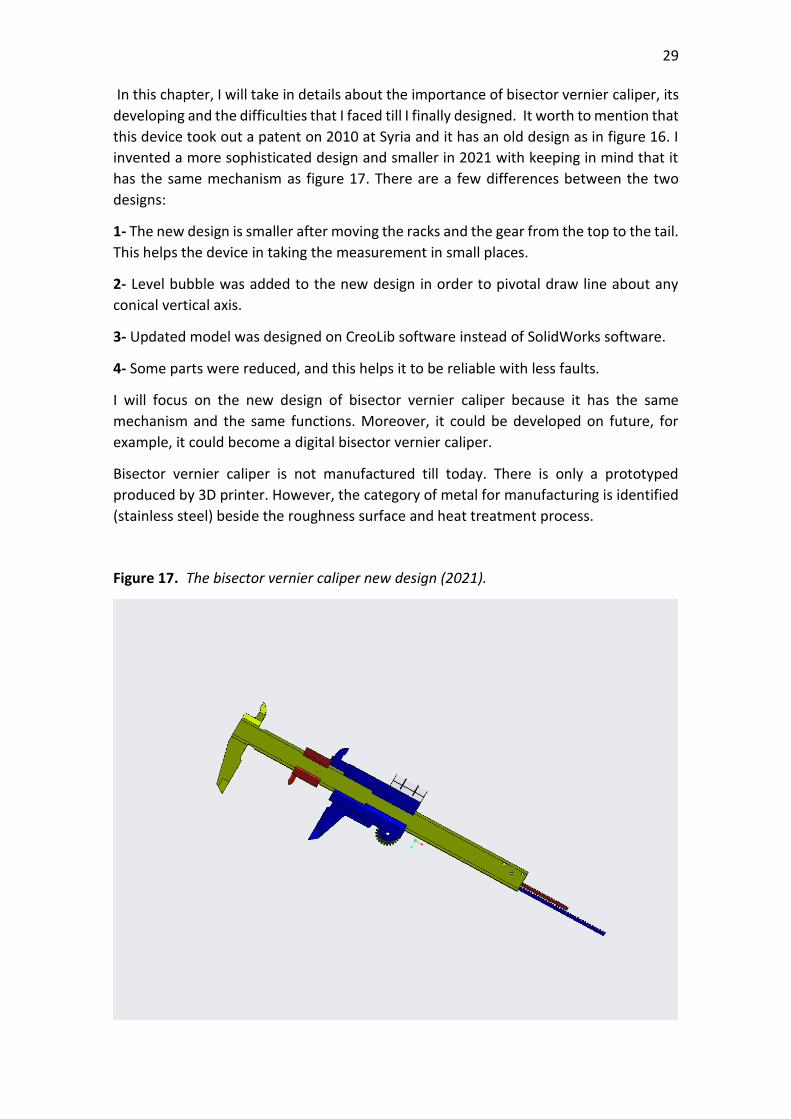
In this chapter, I will take in details about the importance of bisector vernier caliper, its
developing and the difficulties that I faced till I finally designed. It worth to mention that
this device took out a patent on 2010 at Syria and it has an old design as in figure 16. I
invented a more sophisticated design and smaller in 2021 with keeping in mind that it
has the same mechanism as figure 17. There are a few differences between the two
designs:
1- The new design is smaller after moving the racks and the gear from the top to the tail.
This helps the device in taking the measurement in small places.
2- Level bubble was added to the new design in order to pivotal draw line about any
conical vertical axis.
3- Updated model was designed on CreoLib software instead of SolidWorks software.
4- Some parts were reduced, and this helps it to be reliable with less faults.
I will focus on the new design of bisector vernier caliper because it has the same
mechanism and the same functions. Moreover, it could be developed on future, for
example, it could become a digital bisector vernier caliper.
Bisector vernier caliper is not manufactured till today. There is only a prototyped
produced by 3D printer. However, the category of metal for manufacturing is identified
(stainless steel) beside the roughness surface and heat treatment process.
Figure 17. The bisector vernier caliper new design (2021).
30
7.1 Principle of Bisector Vernier Caliper
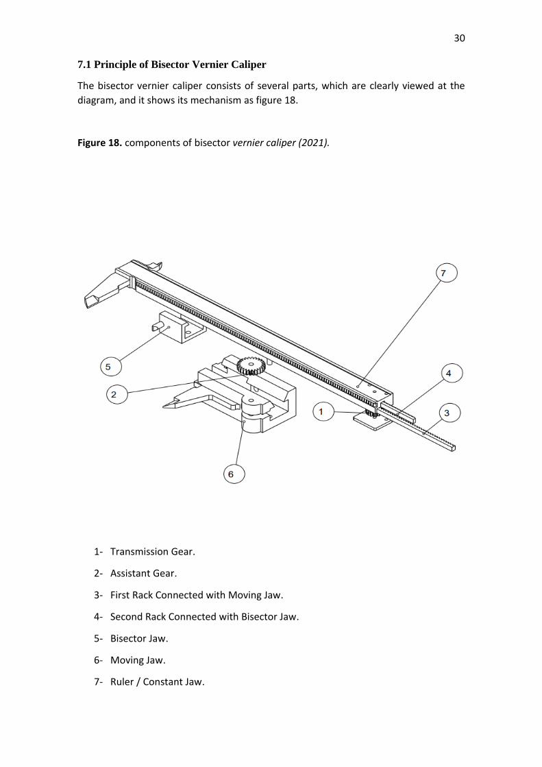
The bisector vernier caliper consists of several parts, which are clearly viewed at the
diagram, and it shows its mechanism as figure 18.
Figure 18. components of bisector vernier caliper (2021).
1- Transmission Gear.
2- Assistant Gear.
3- First Rack Connected with Moving Jaw.
4- Second Rack Connected with Bisector Jaw.
5- Bisector Jaw.
6- Moving Jaw.
7- Ruler / Constant Jaw.
31
7.2 Components of Bisector Vernier Caliper
7.2.1 Ruler
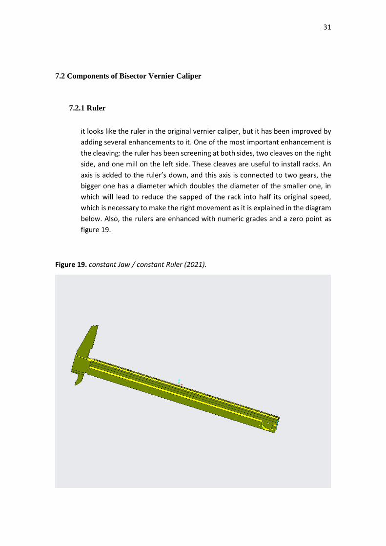
it looks like the ruler in the original vernier caliper, but it has been improved by
adding several enhancements to it. One of the most important enhancement is
the cleaving: the ruler has been screening at both sides, two cleaves on the right
side, and one mill on the left side. These cleaves are useful to install racks. An
axis is added to the ruler’s down, and this axis is connected to two gears, the
bigger one has a diameter which doubles the diameter of the smaller one, in
which will lead to reduce the sapped of the rack into half its original speed,
which is necessary to make the right movement as it is explained in the diagram
below. Also, the rulers are enhanced with numeric grades and a zero point as
figure 19.
Figure 19. constant Jaw / constant Ruler (2021).
32
7.2.2 Rack
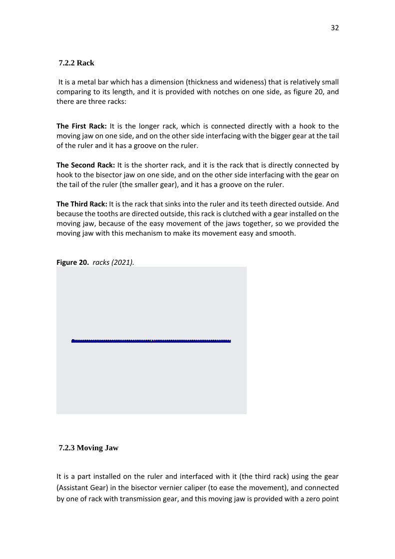
It is a metal bar which has a dimension (thickness and wideness) that is relatively small comparing to its length, and it is provided with notches on one side, as figure 20, and there are three racks:
The First Rack: It is the longer rack, which is connected directly with a hook to the moving jaw on one side, and on the other side interfacing with the bigger gear at the tail of the ruler and it has a groove on the ruler. The Second Rack: It is the shorter rack, and it is the rack that is directly connected by hook to the bisector jaw on one side, and on the other side interfacing with the gear on the tail of the ruler (the smaller gear), and it has a groove on the ruler. The Third Rack: It is the rack that sinks into the ruler and its teeth directed outside. And because the tooths are directed outside, this rack is clutched with a gear installed on the moving jaw, because of the easy movement of the jaws together, so we provided the moving jaw with this mechanism to make its movement easy and smooth. Figure 20. racks (2021).
7.2.3 Moving Jaw
It is a part installed on the ruler and interfaced with it (the third rack) using the gear
(Assistant Gear) in the bisector vernier caliper (to ease the movement), and connected
by one of rack with transmission gear, and this moving jaw is provided with a zero point
33
to match the zero point at the ruler, between the constant jaw and moving jaw we
created a place to position the bisector jaw,
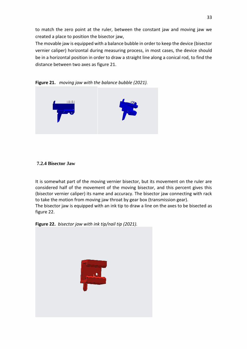
The movable jaw is equipped with a balance bubble in order to keep the device (bisector
vernier caliper) horizontal during measuring process, in most cases, the device should
be in a horizontal position in order to draw a straight line along a conical rod, to find the
distance between two axes as figure 21.
Figure 21. moving jaw with the balance bubble (2021).
7.2.4 Bisector Jaw
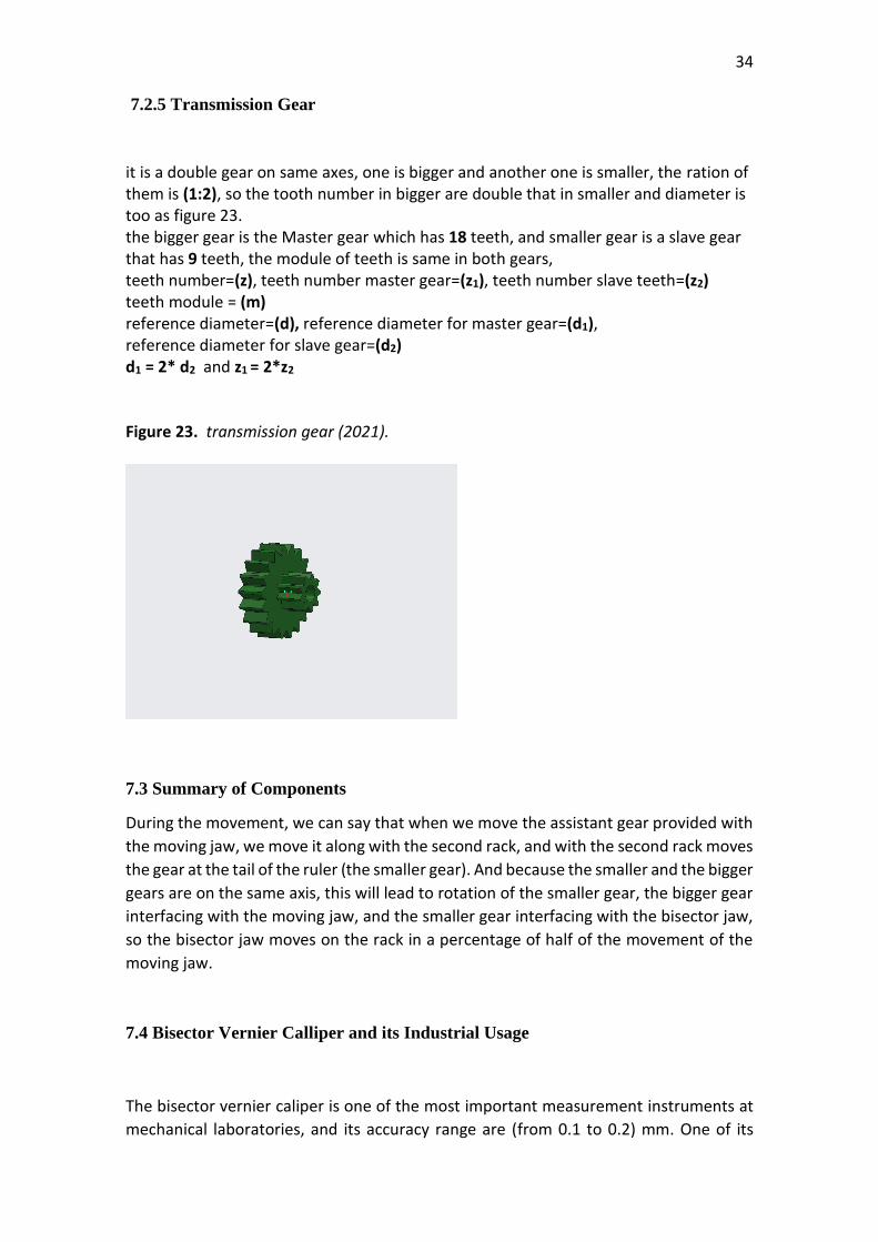
It is somewhat part of the moving vernier bisector, but its movement on the ruler are considered half of the movement of the moving bisector, and this percent gives this (bisector vernier caliper) its name and accuracy. The bisector jaw connecting with rack to take the motion from moving jaw throat by gear box (transmission gear). The bisector jaw is equipped with an ink tip to draw a line on the axes to be bisected as figure 22. Figure 22. bisector jaw with ink tip/nail tip (2021).
34
7.2.5 Transmission Gear
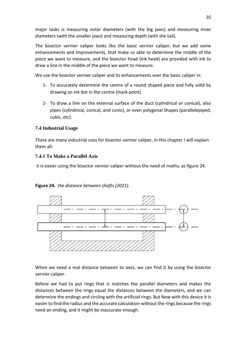
it is a double gear on same axes, one is bigger and another one is smaller, the ration of them is (1:2), so the tooth number in bigger are double that in smaller and diameter is too as figure 23. the bigger gear is the Master gear which has 18 teeth, and smaller gear is a slave gear that has 9 teeth, the module of teeth is same in both gears, teeth number=(z), teeth number master gear=(z1), teeth number slave teeth=(z2) teeth module = (m) reference diameter=(d), reference diameter for master gear=(d1), reference diameter for slave gear=(d2) d1 = 2* d2 and z1 = 2*z2
Figure 23. transmission gear (2021).
7.3 Summary of Components
During the movement, we can say that when we move the assistant gear provided with
the moving jaw, we move it along with the second rack, and with the second rack moves
the gear at the tail of the ruler (the smaller gear). And because the smaller and the bigger
gears are on the same axis, this will lead to rotation of the smaller gear, the bigger gear
interfacing with the moving jaw, and the smaller gear interfacing with the bisector jaw,
so the bisector jaw moves on the rack in a percentage of half of the movement of the
moving jaw.
7.4 Bisector Vernier Calliper and its Industrial Usage
The bisector vernier caliper is one of the most important measurement instruments at
mechanical laboratories, and its accuracy range are (from 0.1 to 0.2) mm. One of its
35
major tasks is measuring outer diameters (with the big jaws) and measuring inner
diameters (with the smaller jaws) and measuring depth (with the tail).
The bisector vernier caliper looks like the basic vernier caliper, but we add some
enhancements and improvements, that make us able to determine the middle of the
piece we want to measure, and the bisector head (ink head) are provided with ink to
draw a line in the middle of the piece we want to measure.
We use the bisector vernier caliper and its enhancements over the basic caliper in:
1- To accurately determine the centre of a round shaped piece and fully solid by
drawing an ink dot in the centre (mark point).
2- To draw a line on the external surface of the duct (cylindrical or conical), also
pipes (cylindrical, conical, and conic), or even polygonal Shapes (parallelepiped,
cubic, etc).
7.4 Industrial Usage
There are many industrial uses for bisector vernier caliper, in this chapter I will explain
them all:
7.4.1 To Make a Parallel Axis
it is easier using the bisector vernier caliper without the need of maths, as figure 24.
Figure 24. the distance between shafts (2021).
When we need a real distance between to axes, we can find it by using the bisector
vernier caliper.
Before we had to put rings that is matches the parallel diameters and makes the
distances between the rings equal the distances between the diameters, and we can
determine the endings and circling with the artificial rings. But Now with this device it is
easier to find the radius and the accurate calculation without the rings because the rings
need an ending, and it might be inaccurate enough.
36
but the bisector vernier caliper does not need an ending and its accuracy is (1/20) mm,
so it has a high accuracy in measuring the distances between water pipes, no matter it
is cylindrical or conical or conic. And at different diameters as in figure 25.
This method is used during the installation of water mixers, or the gas-oil mixers in the
internal-combustion engines.
Figure 25. distance between the conic tubes (2021).
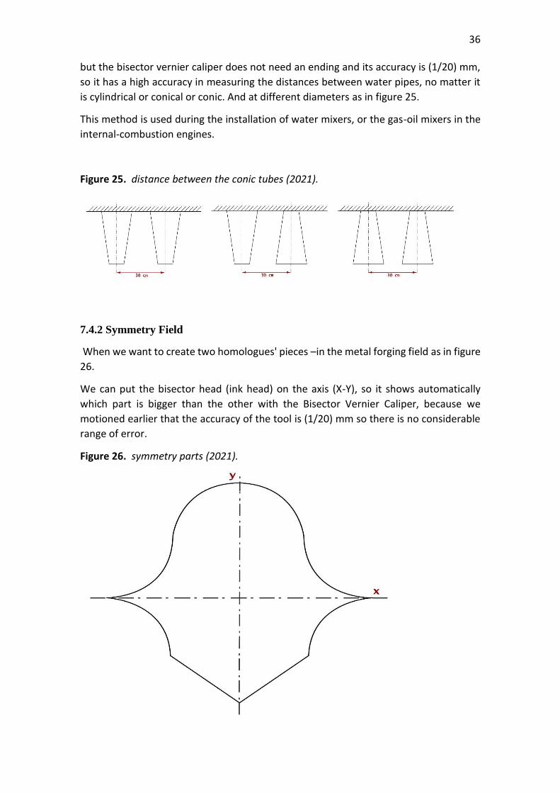
7.4.2 Symmetry Field
When we want to create two homologues' pieces –in the metal forging field as in figure
26.
We can put the bisector head (ink head) on the axis (X-Y), so it shows automatically
which part is bigger than the other with the Bisector Vernier Caliper, because we
motioned earlier that the accuracy of the tool is (1/20) mm so there is no considerable
range of error.
Figure 26. symmetry parts (2021).
37
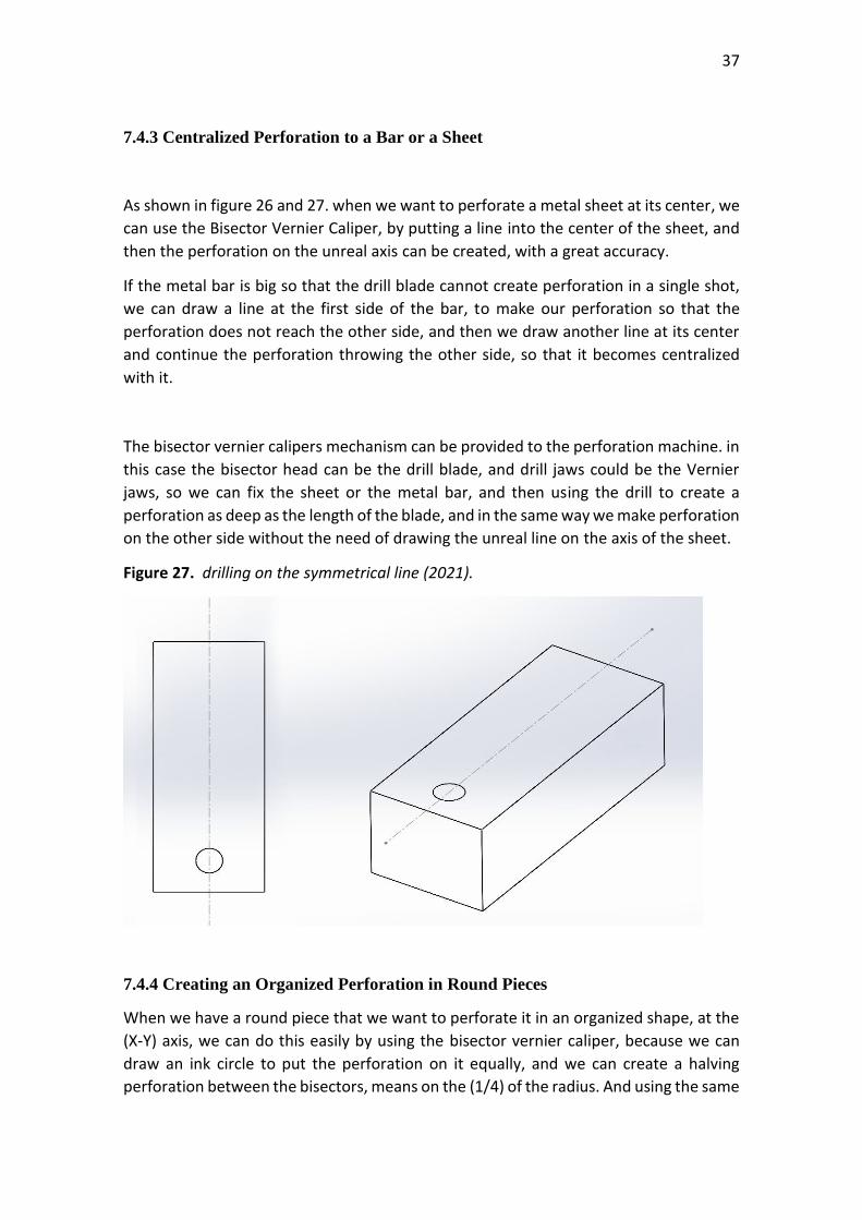
7.4.3 Centralized Perforation to a Bar or a Sheet
As shown in figure 26 and 27. when we want to perforate a metal sheet at its center, we
can use the Bisector Vernier Caliper, by putting a line into the center of the sheet, and
then the perforation on the unreal axis can be created, with a great accuracy.
If the metal bar is big so that the drill blade cannot create perforation in a single shot,
we can draw a line at the first side of the bar, to make our perforation so that the
perforation does not reach the other side, and then we draw another line at its center
and continue the perforation throwing the other side, so that it becomes centralized
with it.
The bisector vernier calipers mechanism can be provided to the perforation machine. in
this case the bisector head can be the drill blade, and drill jaws could be the Vernier
jaws, so we can fix the sheet or the metal bar, and then using the drill to create a
perforation as deep as the length of the blade, and in the same way we make perforation
on the other side without the need of drawing the unreal line on the axis of the sheet.
Figure 27. drilling on the symmetrical line (2021).
7.4.4 Creating an Organized Perforation in Round Pieces
When we have a round piece that we want to perforate it in an organized shape, at the
(X-Y) axis, we can do this easily by using the bisector vernier caliper, because we can
draw an ink circle to put the perforation on it equally, and we can create a halving
perforation between the bisectors, means on the (1/4) of the radius. And using the same
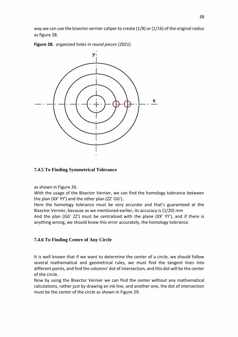
38
way we can use the bisector vernier caliper to create (1/8) or (1/16) of the original radius
as figure 28.
Figure 28. organized holes in round pieces (2021).
7.4.5 To Finding Symmetrical Tolerance
as shown in Figure 26. With the usage of the Bisector Vernier, we can find the homology tolerance between the plan (XX' YY') and the other plan (ZZ' GG'). Here the homology tolerance must be very accurate and that’s guaranteed at the Bisector Vernier, because as we mentioned earlier, its accuracy is (1/20) mm And the plan (GG' ZZ') must be centralized with the plane (XX' YY'), and if there is anything wrong, we should know this error accurately, the homology tolerance. 7.4.6 To Finding Centre of Any Circle
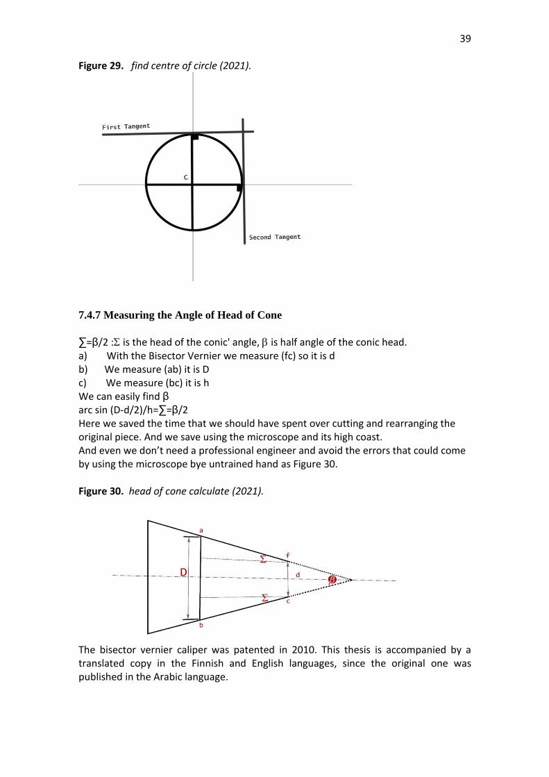
It is well known that if we want to determine the center of a circle, we should follow several mathematical and geometrical rules, we must find the tangent lines into different points, and find the columns' dot of intersection, and this dot will be the center of the circle. Now by using the Bisector Vernier we can find the center without any mathematical calculations, rather just by drawing an ink line, and another one, the dot of intersection must be the center of the circle as shown in Figure 29.
39
Figure 29. find centre of circle (2021).
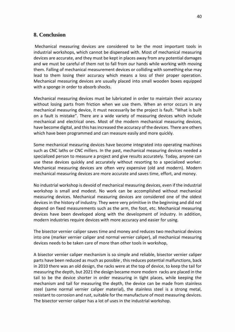
7.4.7 Measuring the Angle of Head of Cone
∑=β/2 : is the head of the conic' angle, is half angle of the conic head. a) With the Bisector Vernier we measure (fc) so it is d b) We measure (ab) it is D c) We measure (bc) it is h We can easily find β
arc sin (D-d/2)/h=∑=β/2 Here we saved the time that we should have spent over cutting and rearranging the original piece. And we save using the microscope and its high coast. And even we don’t need a professional engineer and avoid the errors that could come by using the microscope bye untrained hand as Figure 30. Figure 30. head of cone calculate (2021).
The bisector vernier caliper was patented in 2010. This thesis is accompanied by a translated copy in the Finnish and English languages, since the original one was published in the Arabic language.
40
8. Conclusion Mechanical measuring devices are considered to be the most important tools in industrial workshops, which cannot be dispensed with. Most of mechanical measuring devices are accurate, and they must be kept in places away from any potential damages and we must be careful of them not to fall from our hands while working with moving them. Falling of mechanical measurement devices or colliding with something else may lead to them losing their accuracy which means a loss of their proper operation. Mechanical measuring devices are usually placed into small wooden boxes equipped with a sponge in order to absorb shocks. Mechanical measuring devices must be lubricated in order to maintain their accuracy without losing parts from friction when we use them. When an error occurs in any mechanical measuring device, it must necessarily be the project is fault. “What is built on a fault is mistake”. There are a wide variety of measuring devices which include mechanical and electrical ones. Most of the modern mechanical measuring devices, have become digital, and this has increased the accuracy of the devices. There are others which have been programmed and can measure easily and more quickly. Some mechanical measuring devices have become integrated into operating machines such as CNC laths or CNC millers. In the past, mechanical measuring devices needed a specialized person to measure a project and give results accurately. Today, anyone can use these devices quickly and accurately without resorting to a specialized worker. Mechanical measuring devices are often very expensive (old and modern). Modern mechanical measuring devices are more accurate and saves time, effort, and money. No industrial workshop is devoid of mechanical measuring devices, even if the industrial workshop is small and modest. No work can be accomplished without mechanical measuring devices. Mechanical measuring devices are considered one of the oldest devices in the history of industry. They were very primitive in the beginning and did not depend on fixed measurements such as the arm, the foot, etc. Mechanical measuring devices have been developed along with the development of industry. In addition, modern industries require devices with more accuracy and easier for using. The bisector vernier caliper saves time and money and reduces two mechanical devices into one (marker vernier caliper and normal vernier caliper), all mechanical measuring devices needs to be taken care of more than other tools in workshop, A bisector vernier caliper mechanism is so simple and reliable, bisector vernier caliper parts have been reduced as much as possible , this reduces potential malfunctions, back in 2010 there was an old design, the racks were at the top of device, to keep the tail for measuring the depth, but 2021 the design became more modern racks are placed in the tail to be the device shorter in order measuring in tight places, while keeping the mechanism and tail for measuring the depth, the device can be made from stainless steel (same normal vernier caliper material), the stainless steel is a strong metal, resistant to corrosion and rust, suitable for the manufacture of most measuring devices. The bisector vernier caliper has a lot of uses in the industrial workshop.
41
References
Americana, Encyclopedia. (1988). Micrometer, Encyclopedia Americana.
Barrow, J. (1750). called the device a Vernier scale, Navigatio britannica: or a complete
system of navigation ... (London, England: W. and J. Mount and T. Page, 1750), pp. 140–142, especially page 142.
Christy, S and Amanda, Math-in-CTE Lesson Plan Template. Colin, A. (1994) Needham, Joseph, the Shorter Science and Civilisation in China: 4.
Cambridge University Press. p. 36. adjustable outside caliper gauge... self-dated at AD 9. An abridged version.
Daumas, M. (1989). Scientific Instruments of the Seventeenth and Eighteenth
Centuries and Their Makers, Portman Books, London. Davim, J. (2010). Paulo, Surface Integrity in Machining, Springer-Verlag London
Limited. Davis, R. (1966). Foote, Francis, Kelly, Joe, Surveying, Theory and Practice, McGraw-Hill
Book Company. Dhiren, M. Doshi and Ratna, (2009). New Living Science PHYSICS for CLASS 9 With
More Numerical Problems, p.1-52. Drak, P, Jr. (1999) Dimensioning and toleranceing. Enache, Ş. (1972). La qualité des surfaces usinées (Transl.: Quality of machined
surfaces). Dunod, Paris, P.343. Feng, Z, James Bounds, Aysenur Bicer, James Strohaber, Alexandre A. Kolomenskii,
Christoph Gohle, Mahmood Amani, and Hans A. Schuessler, (2014). "Near infrared frequency comb vernier spectrometer for broadband trace gas detection," Opt.
42
Husu, A.P, Vitenberg, Iu.R., Palmov, V. A, (1975). Sherohovatost poverhnostei
(Teoretiko-veroiatnostnii podhod) (Transl.: Surface roughness (theoretical-probabilistic approach)), Izdatelstvo "Nauka", Moskva, P342.
Kwan, A. (2011). "Vernier scales and other early devices for precise measurement".
American Journal of Physics. Lalande, J. (1764), Astronomie, vol. 2 (Paris, France: Desaint & Saillant), P. 859-860. Mang, W, R. (2014), Bronze Caliper, Archived from the original on (31 August 2014.
Retrieved 26 November 2013). Rank Taylor-Hobson Co. (1996). Bristol, Whitehouse, D. Handbook of Surface
Metrology, Institute. Rbinovich, S, G. (2005). Measurement errors and uncertainties. Sabhadiya, J. (2021). What is micrometer? How do you read a micrometer? Singh, J. IIT JEE, (2018). Physics Topic-wise Complete Solutions p.1-12. Singh, J. and Chaturvedi, S. (2019), 100 Solved Problems on Units, Dimensions and
Measurement. Takatsu-K and Kawasaki-S, (2015). Quick Guide to Precision Measuring instruments,
p.2-8. Vernier P. (1631), La Construction, l'Usage et les Propriétez du Quadrant Nouveau de
Mathématique [The Construction, Use, and Properties of the New Mathematical Quadrant] (in French). Brussels, (Belgium): Francois Vivien.
Waitelet, E, L. (1964). "Micrometer with adjustable barrel sleeve. Wickham, J, R, (1916). English and American Tool Builders New Haven, Connecticut:
Yale University Press, Reprinted by McGraw-Hill, New York and London (1926); and by Lindsay Publications, Inc., Bradley, Illinois.
43
Images Links Base Pitch (TechnicalData, 2019, p.70)
https://www.scribd.com/document/415692343/TechnicalData-KGSTOCKGEARS-pdf
Calipers (Blick, 2021) https://www.dickblick.com/categories/ceramics-
sculpture/tools/calipers/ Chordal Tooth Thickness for Standard Gear (TechnicalData , 2019, p.69)
https://www.scribd.com/document/415692343/TechnicalData-KGSTOCKGEARS-pdf
Engineering choice https://www.engineeringchoice.com/micrometer/ Formula of Micrometer (DearHindi.com, 2021)
https://www.dearhindi.com/2020/05/micrometer-least-count.html Gear Tooth Vernier Caliper (indiamart, 2021)
https://www.indiamart.com/proddetail/gear-tooth-vernier-5622396012.html
How We Use Roughness Tester (elcometer, 2016)
https://www.elcometer.com/pub/media/contentmanager/content///7062.pdf
Measurement with Gear Tooth Vernier Calipers (TechnicalData , 2019, p.69)
https://www.scribd.com/document/415692343/TechnicalData-KGSTOCKGEARS-pdf
Mechanical Tachometer RPM, (2040 parts, 2021) http://www.2040-
parts.com/stewart-warner-black-face-9000-rpm-mechanical-tach-tachometer-826065-i1176006/
Micrometer Parts (Takatsu-ku, Kawasaki-shi, 2015, p.8-16)
https://serolfitnas.blogspot.com/2015/09/quick-guide-to-precision-measurement.html

44
Pressure Measuring Tool, (homida, 2021) https://homida.com/measuring-tools/ surface tester / roughness teaster (FREER, 2021) https://www.freertool.com/178-561-
02a-portable-surface-roughness-tester
1. Vernier Caliper: Parts, Principle, Formula, Least Count, Range, Resolution, Applications, Advantages, and Disadvantages WRITTEN BY MOHAMMED SHAF P.5.
Related Documents