MEASUREMENTS

MEASUREMENTS. Lecture # 1 MEASUREMENTS Why we do measurements? Measurements tell you if the part is worn or damaged Measurements tell you if the parts.
Dec 22, 2015
Welcome message from author
This document is posted to help you gain knowledge. Please leave a comment to let me know what you think about it! Share it to your friends and learn new things together.
Transcript
MEASUREMENTS

Lecture # 1
MEASUREMENTS
MEASUREMENTS
Why we do measurements? Measurements tell you if the part is worn or damaged
Measurements tell you if the parts are out of adjustment or out of specs and by how much.
Example:Measuring the bore or diameter of engine cylinder
Measuring System
1. Metric System(M.K.S)2. S.I System3. Imperial and USC ( United State Customary)
MEASUREMENTS
Measuring System Metric System
Meter(m) for lengthKilogram (Kg) for massSecond (s) for Time
Prefixes
Kilo means 1000Deci means 0.10 (one tenth)Centi (one hundredth)Milli means (one thousandth)
MEASUREMENTS
Measuring System Metric System
Examples:
1Km = 1000m1Kg = 1000gm1Liter = 1000ml
MEASUREMENTS
Measuring System SI System
The International System of Units (abbreviated SI from the French Système international d'unités) is the modern form of the metric system. It is the world's most widely used system of measurement, both in everyday commerce and in science
MEASUREMENTS
The SI was developed in 1960 from the old metre-kilogram-second system
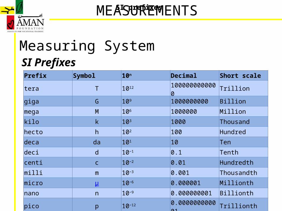
Measuring System SI Prefixes
MEASUREMENTSSI prefixes
Prefix Symbol 10n Decimal Short scale
tera T 1012 1000000000000 Trillion
giga G 109 1000000000 Billion
mega M 106 1000000 Million
kilo k 103 1000 Thousand
hecto h 102 100 Hundred
deca da 101 10 Ten
deci d 10−1 0.1 Tenth
centi c 10−2 0.01 Hundredth
milli m 10−3 0.001 Thousandth
micro μ 10−6 0.000001 Millionth
nano n 10−9 0.000000001 Billionth
pico p 10−12 0.000000000001 Trillionth
SI prefixes
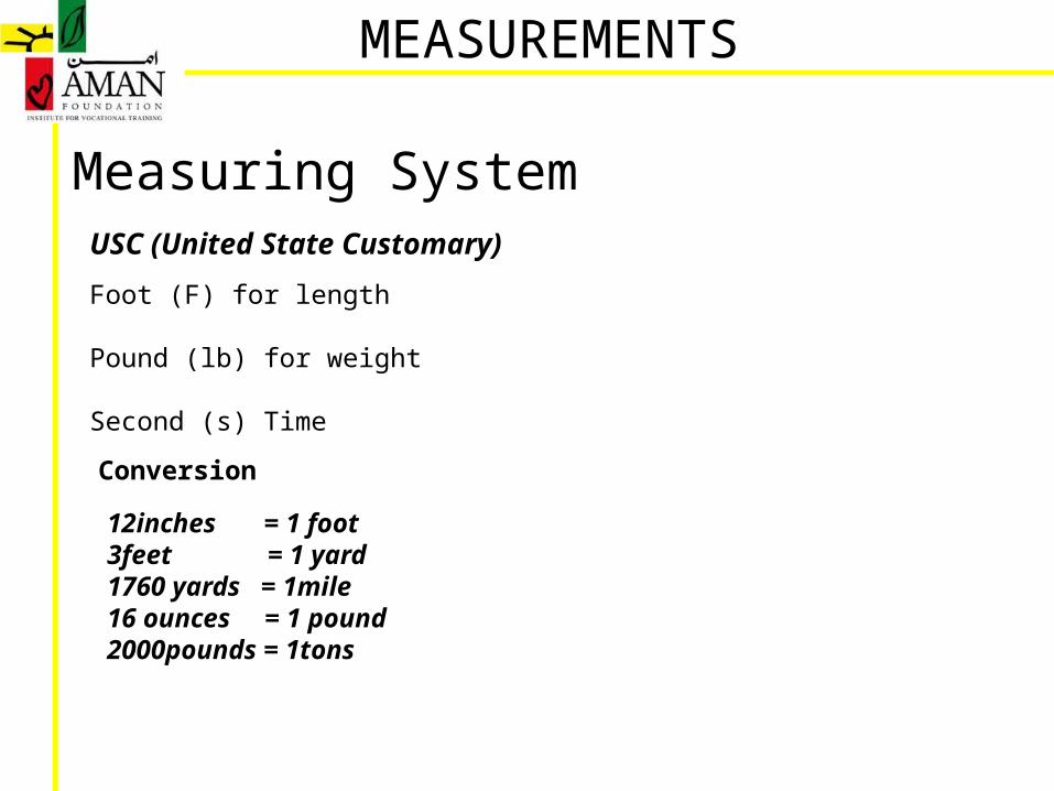
Measuring System USC (United State Customary)
Foot (F) for length Pound (lb) for weight
Second (s) Time
Conversion
12inches = 1 foot3feet = 1 yard1760 yards = 1mile16 ounces = 1 pound2000pounds = 1tons
MEASUREMENTS
Tools and Measurement BasicsAutomotive repairs require the use of a variety of tools and measuring instruments.
These tools are manufactured for use in a particular way, and accurate work and safety can only be assured if they are used correctly.
MEASUREMENTS
MEASUREMENTS
Basic concept for using tools and measuring instruments:
1. Learn the correct uses and functions:Learn the correct uses and functions of each tool and measuring instrument. If used for any purpose other than that specified, the tool or measuring instrument damaged, and parts may be damaged or the quality of the job may be compromised.
2. Learn the correct way to use the instruments:Each tool and measuring instrument has defined operation procedures. Make sure to correctly apply tools against workpieces, apply correct force to the tools, and adopt the proper work postures.
3. Select correctly:There are various tools available for loosening bolts, depending on the size, position and other criteria. Always choose your tools to fit the shape of the part and the place in which the job is being carried out.
Basic concept for using tools and measuring instruments:
4.Try to keep organizedTools and measuring instruments should be positioned so that they can be accessed easily when needed, and replaced in their correct locations once used.
5. Strict adherence to upkeep and management of tools.Tools should be cleaned and where necessary oiled as soon as they have been used. Any necessary repairs should be carried out immediately, so that tools are always in perfect condition.
MEASUREMENTS
Basic concept for using tools and measuring instruments:Points to check before measurement:
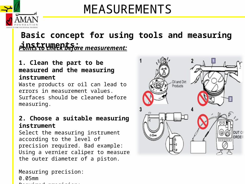
1. Clean the part to be measured and the measuringinstrumentWaste products or oil can lead to errors in measurement values. Surfaces should be cleaned before measuring.
2. Choose a suitable measuring instrumentSelect the measuring instrument according to the level of precision required. Bad example: Using a vernier caliper to measure the outer diameter of a piston.
Measuring precision:0.05mmRequired precision:0.01mm
MEASUREMENTS
Basic concept for using tools and measuring instruments:
3. Calibrate zeroCheck that zero is aligned to its correct position. Zero is the basis for correct measurement.
4. Maintenance of measuring instrumentMaintenance and recalibration should be carried out regularly. Do not use if broken.
Points to check before measurement:
MEASUREMENTS

Basic concept for using tools and measuring instruments:
MEASUREMENTS
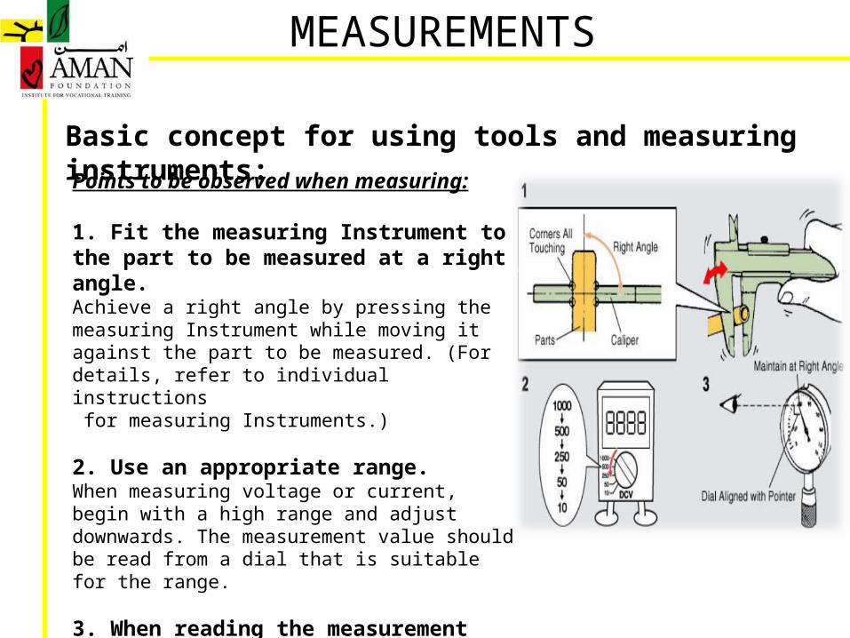
Points to be observed when measuring:
1. Fit the measuring Instrument to the part to be measured at a right angle.Achieve a right angle by pressing the measuring Instrument while moving it against the part to be measured. (For details, refer to individual instructions for measuring Instruments.)
2. Use an appropriate range.When measuring voltage or current, begin with a high range and adjust downwards. The measurement value should be read from a dial that is suitable for the range.
3. When reading the measurement valueMake sure your eye level is at a right angle to the dial and pointer.
Basic concept for using tools and measuring instruments:
MEASUREMENTS
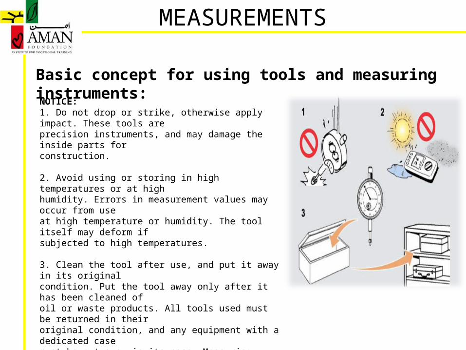
NOTICE:1. Do not drop or strike, otherwise apply impact. These tools areprecision instruments, and may damage the inside parts forconstruction.
2. Avoid using or storing in high temperatures or at highhumidity. Errors in measurement values may occur from useat high temperature or humidity. The tool itself may deform ifsubjected to high temperatures.
3. Clean the tool after use, and put it away in its originalcondition. Put the tool away only after it has been cleaned ofoil or waste products. All tools used must be returned in theiroriginal condition, and any equipment with a dedicated casemust be put away in its case. Measuring tools must be storedin a defined place. If tools are to be stored for a long term,apply rust protection oil where necessary, and removebatteries.
Measuring Instruments• Steel Scale
• Inside and outside caliper
• Vernier Caliper
• Micrometer
• Dial Gauge
• Feeler Gauge
• Plasti Gauge
• Wire Gauge
• Multimeter
MEASUREMENTS
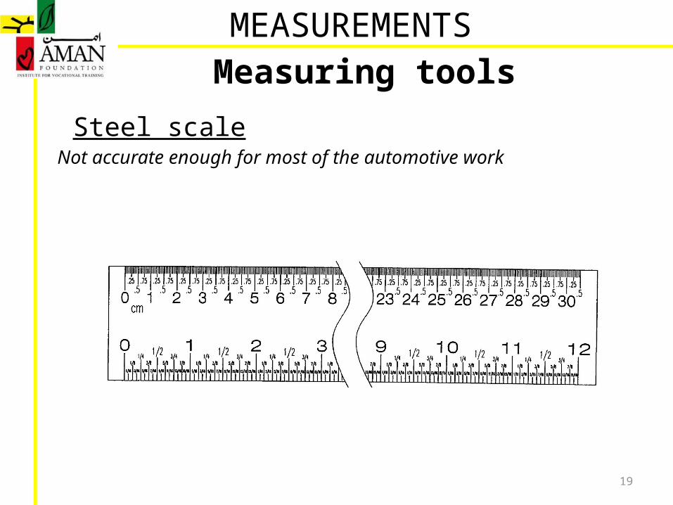
Measuring tools
Steel scaleNot accurate enough for most of the automotive work
19
MEASUREMENTS
Measuring tools
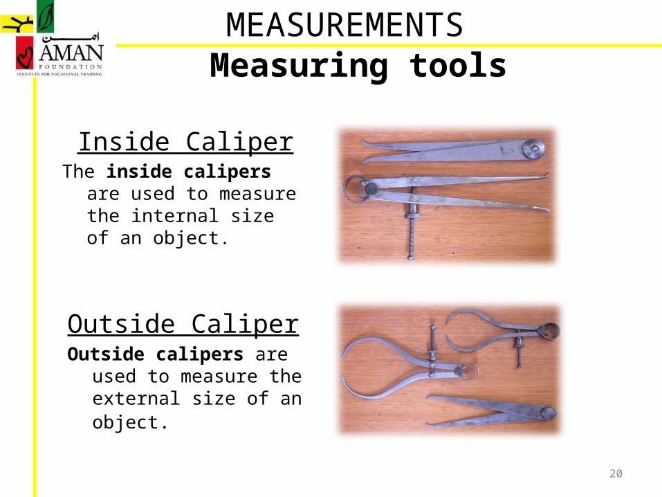
Inside CaliperThe inside calipers are used to
measure the internal size of an object.
20
Outside CaliperOutside calipers are used to
measure the external size of an object.
MEASUREMENTS

Lecture # 2
MEASUREMENTS
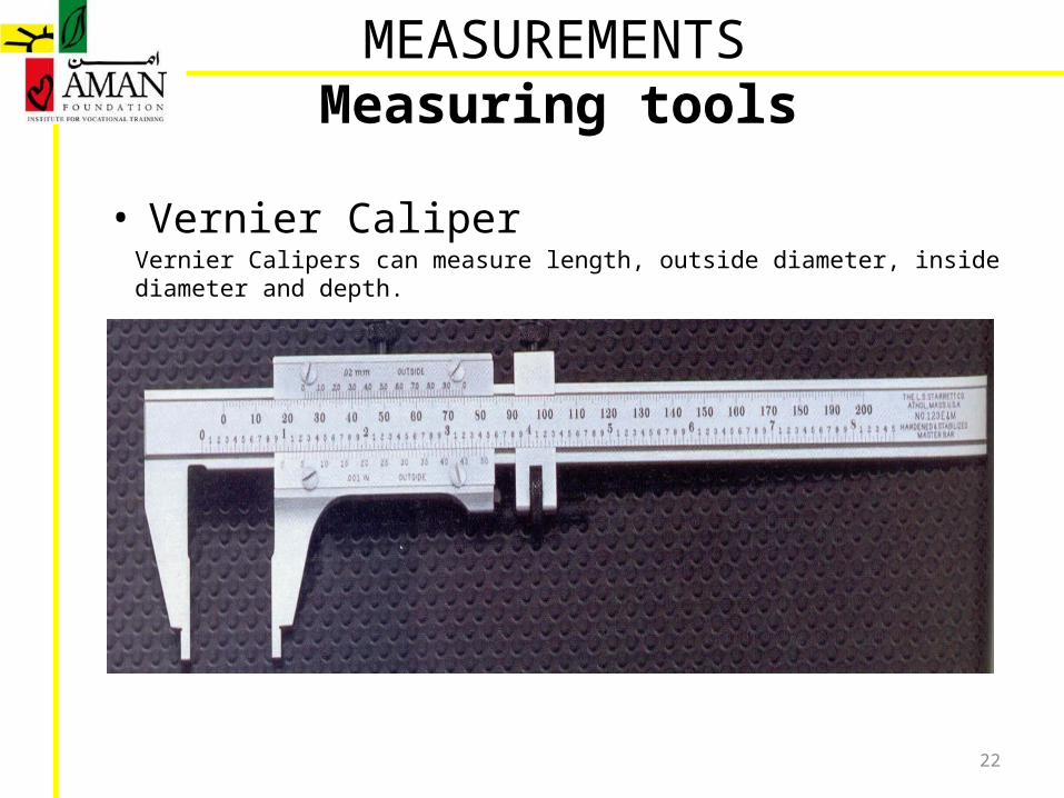
• Vernier Caliper
22
Vernier Calipers can measure length, outside diameter, inside diameter and depth.
MEASUREMENTSMeasuring tools
• Vernier Caliper
23
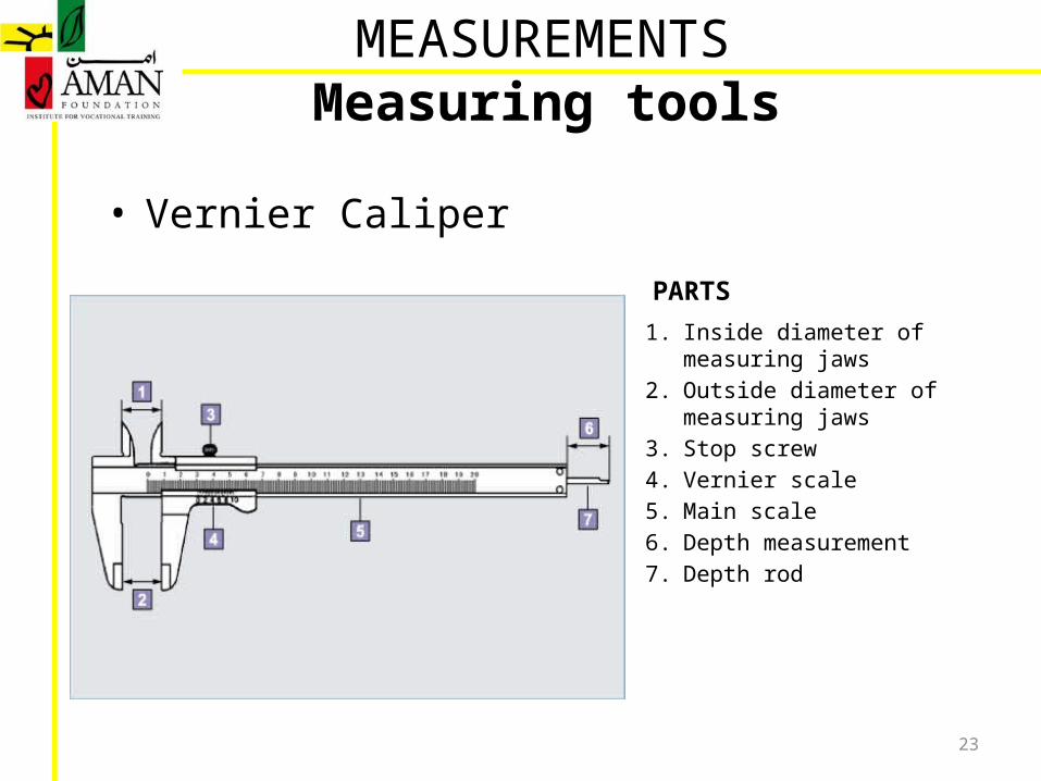
1. Inside diameter of measuring jaws2. Outside diameter of measuring jaws3. Stop screw4. Vernier scale5. Main scale6. Depth measurement7. Depth rod
MEASUREMENTSMeasuring tools
PARTS
• Vernier Caliper
24
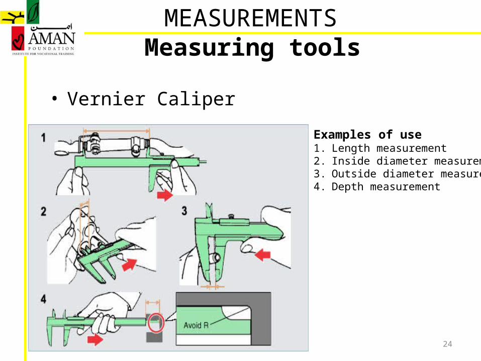
Examples of use1. Length measurement 2. Inside diameter measurement 3. Outside diameter measurement 4. Depth measurement
MEASUREMENTSMeasuring tools
• Vernier Caliper
25
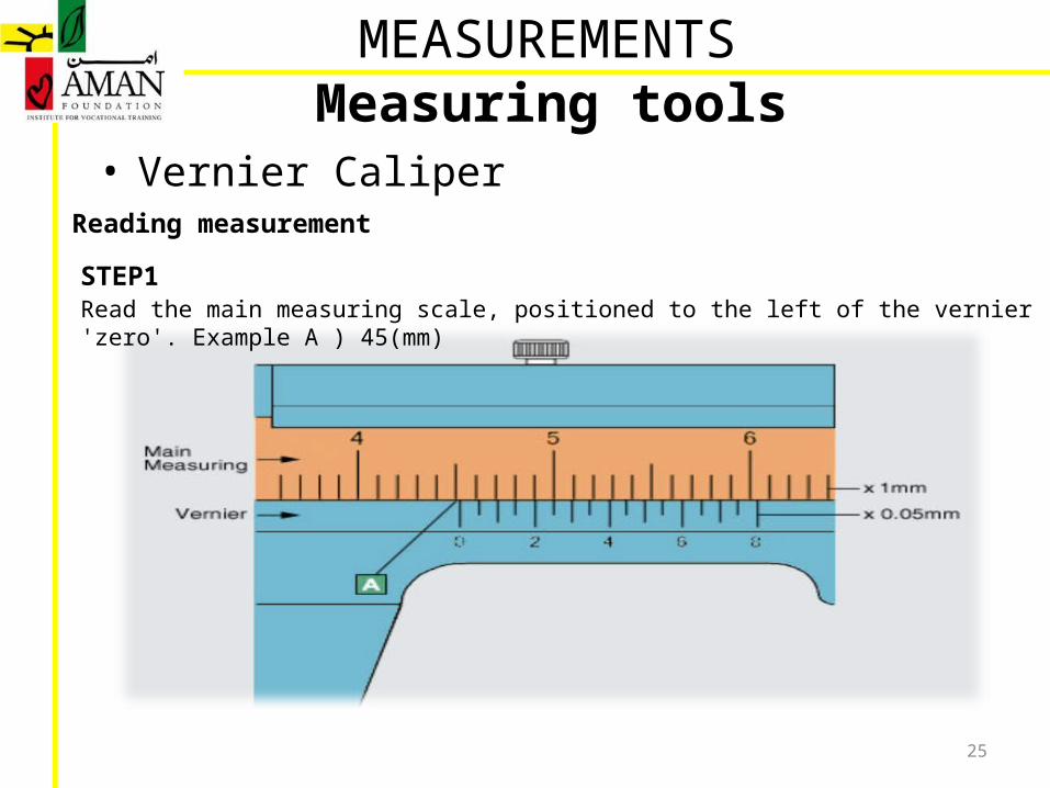
Reading measurement
MEASUREMENTSMeasuring tools
Read the main measuring scale, positioned to the left of the vernier 'zero'. Example A ) 45(mm)STEP1
• Vernier Caliper
26
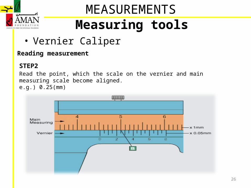
Reading measurement
MEASUREMENTSMeasuring tools
Read the point, which the scale on the vernier and main measuring scale become aligned.e.g.) 0.25(mm)
STEP2
• Vernier Caliper
27
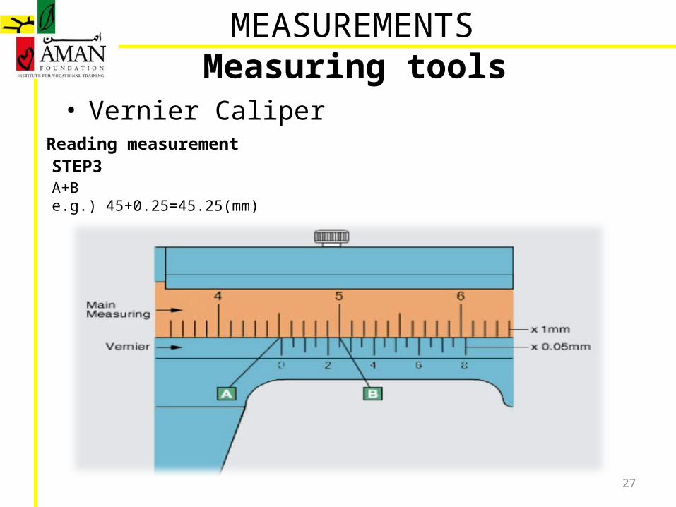
Reading measurement
MEASUREMENTSMeasuring tools
A+B e.g.) 45+0.25=45.25(mm)
STEP3

Lecture # 3
MEASUREMENTS
29
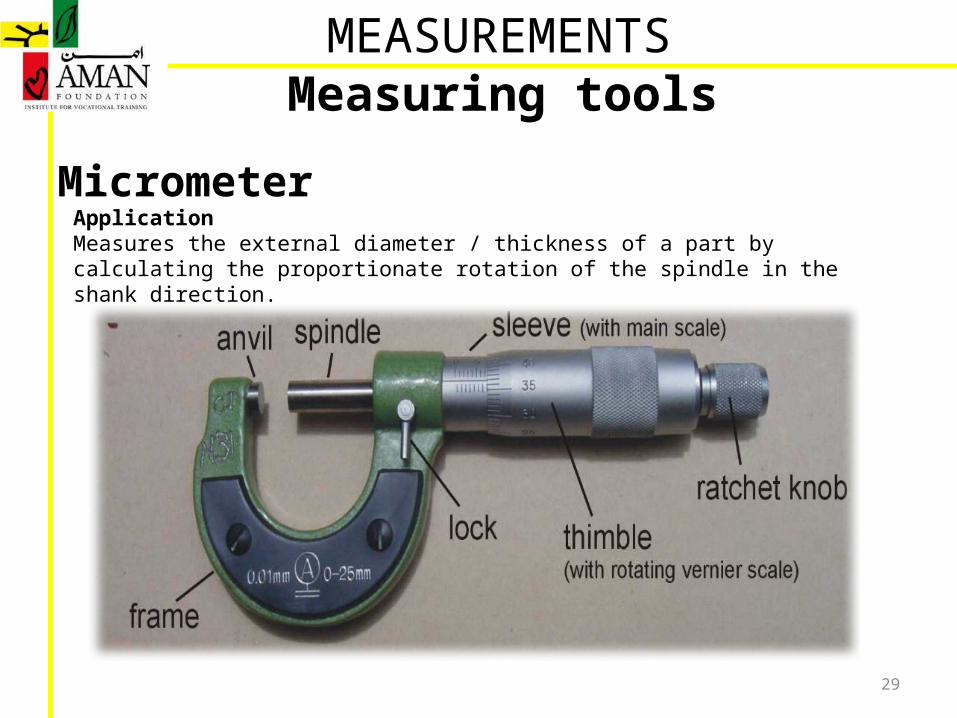
MicrometerApplication Measures the external diameter / thickness of a part by calculating the proportionate rotation of the spindle in the shank direction.
MEASUREMENTSMeasuring tools
30
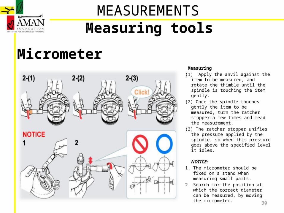
Micrometer Measuring (1) Apply the anvil against the item to be
measured, and rotate the thimble until the spindle is touching the item gently.
(2) Once the spindle touches gently the item to be measured, turn the ratcher stopper a few times and read the measurement.
(3) The ratcher stopper unifies the pressure applied by the spindle, so when this pressure goes above the specified level it idles.
NOTICE: 1. The micrometer should be fixed on
a stand when measuring small parts.
2. Search for the position at which the correct diameter can be measured, by moving the micrometer.
MEASUREMENTSMeasuring tools
31
Micrometer
MEASUREMENTSMeasuring tools
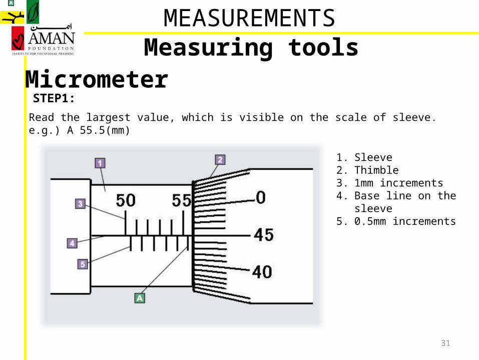
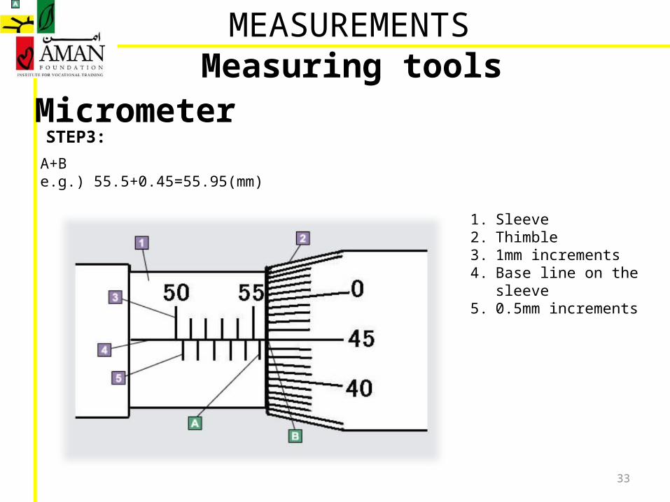
Read the largest value, which is visible on the scale of sleeve. e.g.) A 55.5(mm)
1. Sleeve2. Thimble3. 1mm increments4. Base line on the sleeve5. 0.5mm increments
STEP1:
32
Micrometer
MEASUREMENTSMeasuring tools
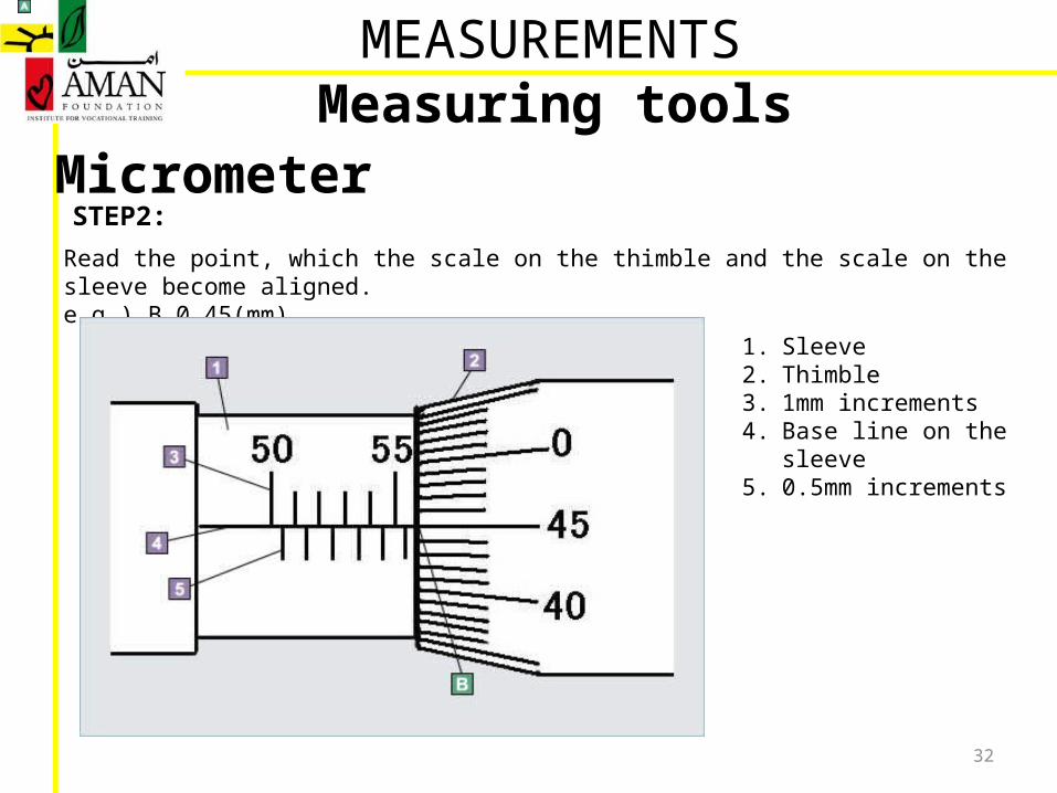
Read the point, which the scale on the thimble and the scale on the sleeve become aligned.e.g.) B 0.45(mm)
1. Sleeve2. Thimble3. 1mm increments4. Base line on the sleeve5. 0.5mm increments
STEP2:
33
Micrometer
MEASUREMENTSMeasuring tools
A+Be.g.) 55.5+0.45=55.95(mm)
1. Sleeve2. Thimble3. 1mm increments4. Base line on the sleeve5. 0.5mm increments
STEP3:
34
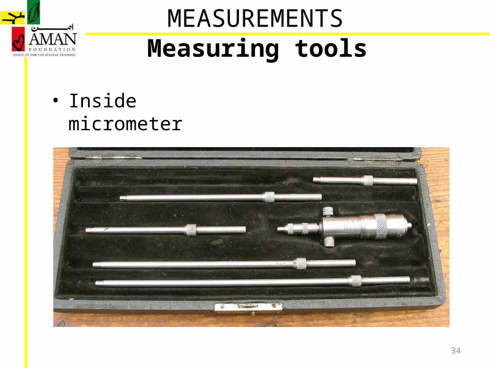
• Inside micrometer
MEASUREMENTSMeasuring tools
Lecture # 4
MEASUREMENTS
36
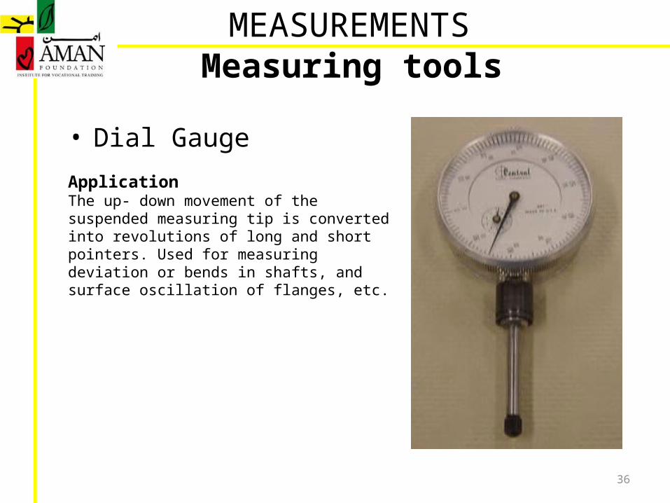
• Dial Gauge
MEASUREMENTSMeasuring tools
Application The up- down movement of the suspended measuring tip is converted into revolutions of long and short pointers. Used for measuring deviation or bends in shafts, and surface oscillation of flanges, etc.
37
• Dial Gauge
MEASUREMENTSMeasuring tools
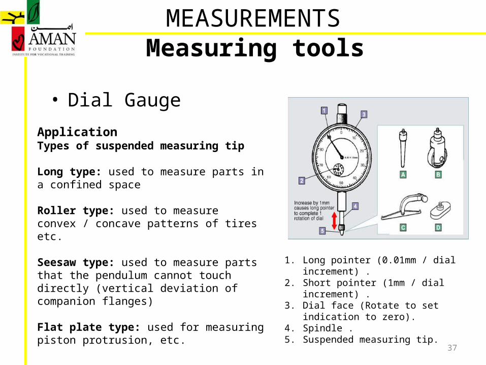
Application Types of suspended measuring tip
Long type: used to measure parts in a confined space
Roller type: used to measure convex / concave patterns of tires etc.
Seesaw type: used to measure parts that the pendulum cannot touch directly (vertical deviation of companion flanges)
Flat plate type: used for measuring piston protrusion, etc.
1. Long pointer (0.01mm / dial increment) .2. Short pointer (1mm / dial increment) .3. Dial face (Rotate to set indication to zero).4. Spindle .5. Suspended measuring tip.
38
• Dial Gauge
MEASUREMENTSMeasuring tools
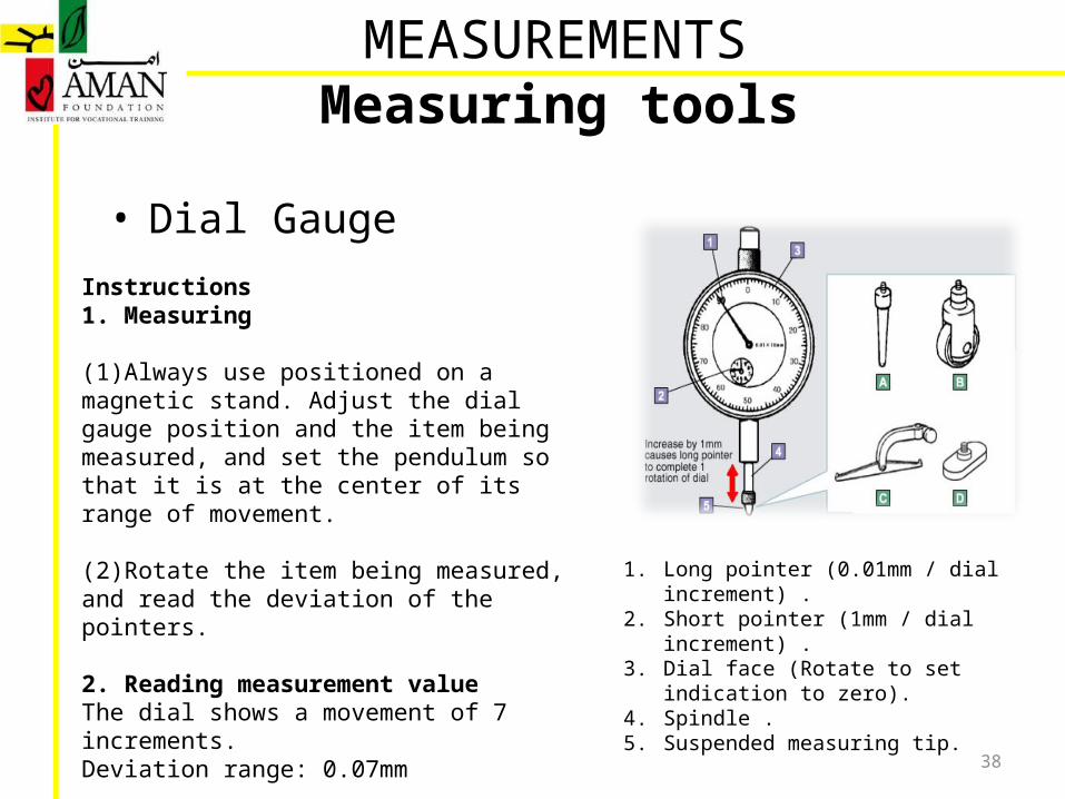
Instructions 1. Measuring
(1)Always use positioned on a magnetic stand. Adjust the dial gauge position and the item being measured, and set the pendulum so that it is at the center of its range of movement.
(2)Rotate the item being measured, and read the deviation of the pointers.
2. Reading measurement value The dial shows a movement of 7 increments. Deviation range: 0.07mm
1. Long pointer (0.01mm / dial increment) .2. Short pointer (1mm / dial increment) .3. Dial face (Rotate to set indication to zero).4. Spindle .5. Suspended measuring tip.
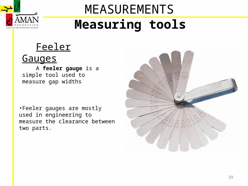
Feeler Gauges A feeler gauge is a simple tool used
to measure gap widths
39
•Feeler gauges are mostly used in engineering to measure the clearance between two parts.
Measuring toolsMEASUREMENTS
Feeler Gauges
40
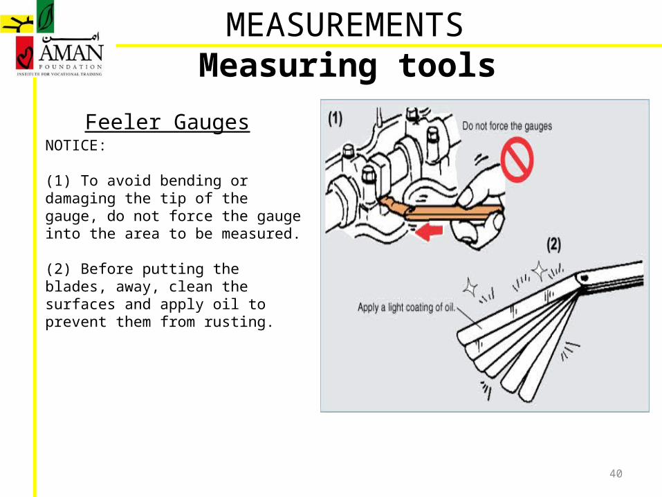
NOTICE:
(1) To avoid bending or damaging the tip of the gauge, do not force the gauge into the area to be measured.
(2) Before putting the blades, away, clean the surfaces and apply oil to prevent them from rusting.
Measuring toolsMEASUREMENTS
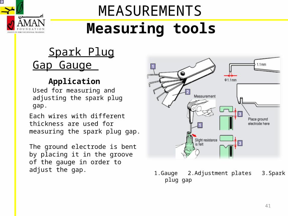
Spark Plug Gap Gauge Application
Used for measuring and adjusting the spark plug gap.
41
Each wires with different thickness are used for measuring the spark plug gap.
The ground electrode is bent by placing it in the groove of the gauge in order to adjust the gap.
Measuring toolsMEASUREMENTS
1.Gauge 2.Adjustment plates 3.Spark plug gap
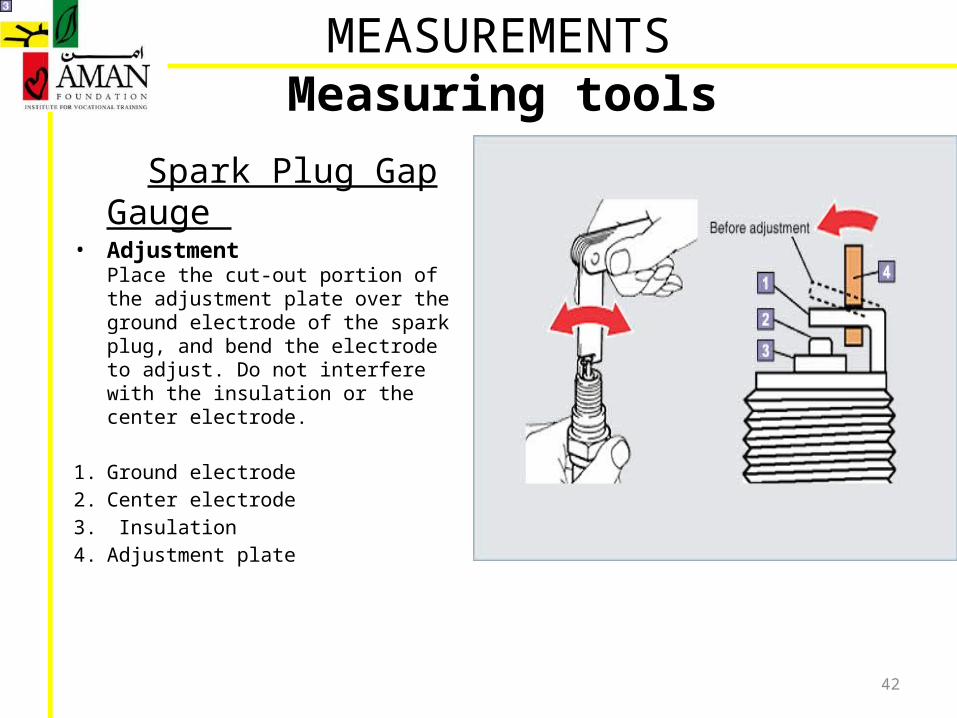
Spark Plug Gap Gauge • Adjustment
Place the cut-out portion of the adjustment plate over the ground electrode of the spark plug, and bend the electrode to adjust. Do not interfere with the insulation or the center electrode.
1. Ground electrode 2. Center electrode3. Insulation 4. Adjustment plate
42
Measuring toolsMEASUREMENTS

Lecture # 5
MEASUREMENTS
44
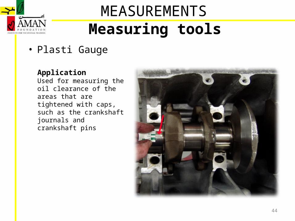
• Plasti Gauge
ApplicationUsed for measuring the oil clearance of the areas that are tightened with caps, such as the crankshaft journals and crankshaft pins
MEASUREMENTSMeasuring tools
45
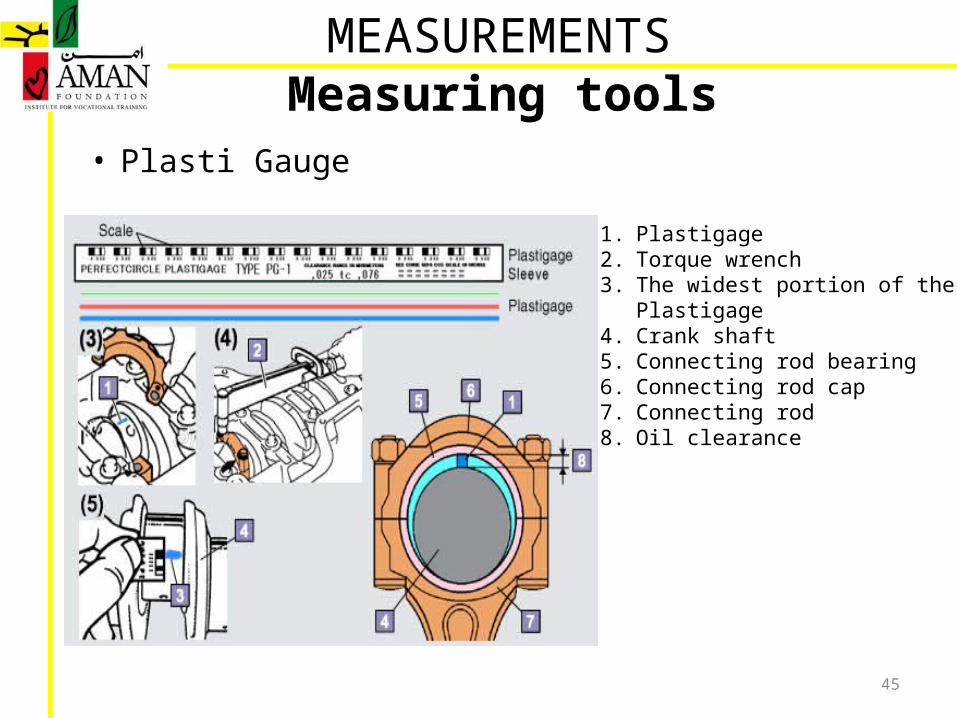
• Plasti Gauge
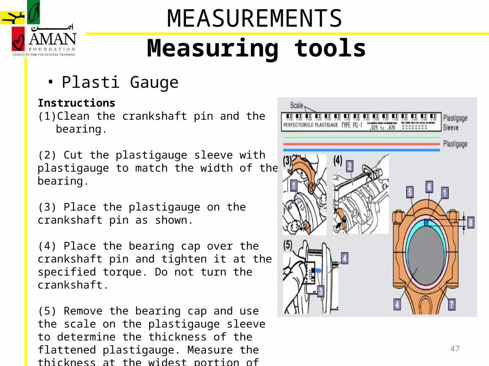
1. Plastigage2. Torque wrench3. The widest portion of the Plastigage4. Crank shaft5. Connecting rod bearing6. Connecting rod cap7. Connecting rod8. Oil clearance
MEASUREMENTSMeasuring tools

46
• Plasti Gauge
Plastigage is made of soft plastic, and comes in three colors, eachindicating a different thickness
Clearance measurement ranges:Green: 0.025 ~ 0.076mmRed: 0.051 ~ 0.152mmBlue: 0.102 ~ 0.229mm
MEASUREMENTSMeasuring tools
47
• Plasti GaugeInstructions(1) Clean the crankshaft pin and the bearing.
(2) Cut the plastigauge sleeve with plastigauge to match the width of the bearing.
(3) Place the plastigauge on the crankshaft pin as shown.
(4) Place the bearing cap over the crankshaft pin and tighten it at the specified torque. Do not turn the crankshaft.
(5) Remove the bearing cap and use the scale on the plastigauge sleeve to determine the thickness of the flattened plastigauge. Measure the thickness at the widest portion of the plastigauge.
MEASUREMENTSMeasuring tools
48
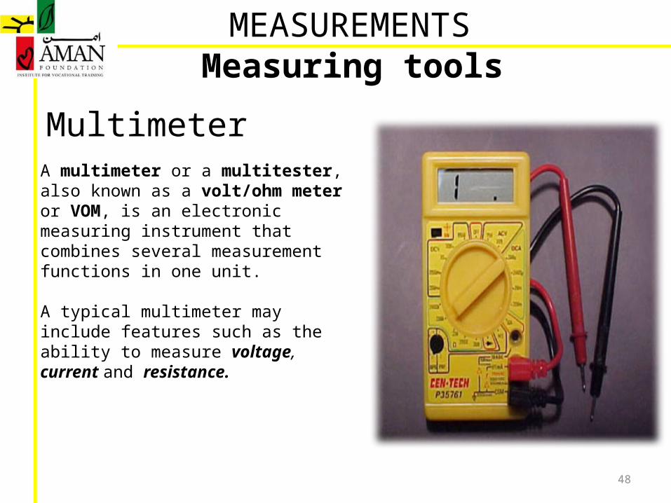
MultimeterA multimeter or a multitester, also known as a volt/ohm meter or VOM, is an electronic measuring instrument that combines several measurement functions in one unit.
A typical multimeter may include features such as the ability to measure voltage, current and resistance.
MEASUREMENTSMeasuring tools
Related Documents