UNCLASSIFIED UNCLASSIFIED AD-E404 223 Contractor Report ARWSE-CR-18002 MEASUREMENT OF COMBUSTION PRODUCTS IN SMALL ARMS BLOWBACK GASES Arnt Johnsen Norwegian Defense Research Establishment (FFI), Kjeller, Norway Adam M. Jacob Douglas Ray Daniel Cler U.S. Army CCDC AC, Picatinny Arsenal, NJ August 2020 Approved for public release; distribution is unlimited. AD U.S. ARMY COMBAT CAPABILITIES DEVELOPMENT COMMAND ARMAMENTS CENTER Weapons and Software Engineering Center Picatinny Arsenal, New Jersey

Welcome message from author
This document is posted to help you gain knowledge. Please leave a comment to let me know what you think about it! Share it to your friends and learn new things together.
Transcript

UNCLASSIFIED
UNCLASSIFIED
AD-E404 223
Contractor Report ARWSE-CR-18002
MEASUREMENT OF COMBUSTION PRODUCTS IN SMALL ARMS BLOWBACK GASES
Arnt Johnsen Norwegian Defense Research Establishment (FFI), Kjeller, Norway
Adam M. Jacob
Douglas Ray Daniel Cler
U.S. Army CCDC AC, Picatinny Arsenal, NJ
August 2020
Approved for public release; distribution is unlimited.
AD
U.S. ARMY COMBAT CAPABILITIES DEVELOPMENT COMMAND ARMAMENTS CENTER
Weapons and Software Engineering Center
Picatinny Arsenal, New Jersey

UNCLASSIFIED
UNCLASSIFIED
The views, opinions, and/or findings contained in this report are those of the author(s) and should not be construed as an official Department of the Army position, policy, or decision, unless so designated by other documentation. The citation in this report of the names of commercial firms or commercially available products or services does not constitute official endorsement by or approval of the U.S. Government. Destroy by any means possible to prevent disclosure of contents or reconstruction of the document. Do not return to the originator.

UNCLASSIFIED
UNCLASSIFIED
REPORT DOCUMENTATION PAGE Form Approved OMB No. 0704-01-0188
The public reporting burden for this collection of information is estimated to average 1 hour per response, including the time for reviewing instructions, searching existing data sources, gathering and maintaining the data needed, and completing and reviewing the collection of information. Send comments regarding this burden estimate or any other aspect of this collection of information, including suggestions for reducing the burden to Department of Defense, Washington Headquarters Services Directorate for Information Operations and Reports (0704-0188), 1215 Jefferson Davis Highway, Suite 1204, Arlington, VA 22202-4302. Respondents should be aware that notwithstanding any other provision of law, no person shall be subject to any penalty for failing to comply with a collection of information if it does not display a currently valid OMB control number. PLEASE DO NOT RETURN YOUR FORM TO THE ABOVE ADDRESS.
1. REPORT DATE (DD-MM-YYYY)
August 2020 2. REPORT TYPE
Final 3. DATES COVERED (From – To)
4. TITLE AND SUBTITLE
Measurement of Combination Products in Small Arms Blowback Gases
5a. CONTRACT NUMBER
5b. GRANT NUMBER
5c. PROGRAM ELEMENT NUMBER
6. AUTHORS
Arnt Johnsen - Norwegian Defense Research Establishment (FFI), Kjeller, Norway Adam M. Jacob, Douglas Ray, and Daniel Cler - U.S. Army CCDC AC, Picatinny Arsenal, NJ
5d. PROJECT NUMBER
5e. TASK NUMBER
5f. WORK UNIT NUMBER
7. PERFORMING ORGANIZATION NAME(S) AND ADDRESS(ES)
U.S. Army CCDC AC, WSEC Norwegian Defense Research Weapons Systems and Technology Establishment (FFI), Directorate (FCDD-ACW-WF) Instituttvn 20, NO-2007 Kjeller Picatinny Arsenal, NJ 07806-5000 Norway
8. PERFORMING ORGANIZATION REPORT NUMBER
9. SPONSORING/MONITORING AGENCY NAME(S) AND ADDRESS(ES)
U.S. Army CCDC AC, ESIC Knowledge & Process Management Office (FCDD-ACE-K) Picatinny Arsenal, NJ 07806-5000
10. SPONSOR/MONITOR’S ACRONYM(S)
11. SPONSOR/MONITOR’S REPORT NUMBER(S)
Contractor Report ARWSE-CR-18002
12. DISTRIBUTION/AVAILABILITY STATEMENT
Approved for public release; distribution is unlimited. 13. SUPPLEMENTARY NOTES
14. ABSTRACT
When a muzzle device, specifically a suppressor, is added to a small arms system, it typically has a tendency to increase the system’s backpressure, therefore increasing the blowback. Different muzzle device designs result in different increases in backpressure, and thus different levels of blowback. If the pressure is high enough when the bolt opens, gas will escape from the barrel and into the operating mechanism. In this effort, electrochemical sensors were used to measure and quantify the combustion products of the blowback gases using suppressed and unsuppressed small arms systems by both a “Chamber Method” as well as a “Breathing Zone Method.” While the combustion products consist of a variety of gases, the three primary toxic constituents are carbon monoxide, ammonia, and hydrogen cyanide. Results showed increased concentrations of gases with the use of suppressors. In addition to gaseous combustion products, metals are also aerosolized during combustion and firing of a round. Aerosolized metals, including copper, zinc, and bismuth, were measured. Results showed that some aerosolized metals become trapped in the suppressor during firing, resulting in lower levels of the aerosolized metals when a suppressor is used, while others are increased proportionally in the blowback gas when a suppressor is used. 15. SUBJECT TERMS
Small arms Blowback Toxicity Metal fever Suppressor Signature suppressor Breathing zone 16. SECURITY CLASSIFICATION OF: 17. LIMITATION OF
ABSTRACT
SAR
18. NUMBER OF PAGES
23
19a. NAME OF RESPONSIBLE PERSON
Adam M. Jacob a. REPORT
U b. ABSTRACT
U c. THIS PAGE
U 19b. TELEPHONE NUMBER (Include area
code) (973) 724-0535 Standard Form 298 (Rev. 8/98)
Prescribed by ANSI Std. Z39.18


UNCLASSIFIED
Approved for public release; distribution is unlimited.
UNCLASSIFIED i
CONTENTS Page
Introduction 1
Experimental Section 2
Background and Methodology 3 Chamber Test Method 8 Breathing Zone Test Method 10
Results and Discussion 11
Chamber Test Method 11 Breathing Zone Test Method 14
Conclusions 16
References 17
Distribution List 19
FIGURES
1 Chamber with weapon muzzle inside (a) and outside (b) 8
2 Weapon and sampling setup for BZTM, left inlet 10
3 Mass of CO produced – all shots 11
4 Actual versus predicted mass of CO 11
5 Summary of fit and ANOVA – CTM 12
6 Interactions between variables – CTM 12
7 Mass of aerial dust produced – full weapon inside chamber (total dust) 13
8 Mass of aerial dust produced – muzzle outside of chamber (blowback dust only) 13
9 Concentration of CO produced – 45-sec time weighted averages – all shots 14
10 Actual versus predicted concentration of CO 15
11 Summary of fit and ANOVA – BZTM 15
12 Interactions between variables – BZTM 16


UNCLASSIFIED
Approved for public release; distribution is unlimited.
UNCLASSIFIED 1
INTRODUCTION
Toxic hazards of small arms weapon systems of the U.S. Army are currently measured using Test Operations Procedure 2-2-614, with measurement focus being on the entire toxicity of the system (ref. 1). There is no standardized method of measuring “blowback” in a small arms system, and, as such, there is a desire to develop one. “Blowback” is the term used to describe the gases and aerosols that emanate from a small arms system’s operating group and chamber area due to backpressure within the system, typically as a result of the addition of a suppressor or other muzzle device (such as a blank firing adaptor) to the weapon system. These gases are blown back toward the operator, thus the term “blowback.”
When a muzzle device, specifically a suppressor, is added to a small arms system, it typically has
a tendency to increase the system’s backpressure, therefore increasing the blowback. Different muzzle device designs result in different increases in backpressure and, therefore, different levels of blowback. A suppressor traps high-pressure gas and blocks the flow from the barrel’s muzzle. Typically, organ piping occurs within the suppressor and barrel. This causes a cyclic effect in the pressure at the chamber that is dictated by the speed of sound in the gas and the overall length of the suppressor and barrel. If the pressure is high enough when the bolt opens, gas will escape from the barrel and into the operating mechanism.
Fundamentally, backpressure is caused by a reduction in flow rate at the muzzle of the barrel due
to an increase in pressure at the muzzle caused by the suppressor. The suppressor, when added to the weapon barrel, operates in two phases relative to the type of gas flow. The first phase is a very dynamic, time varying, shock dependent flow as the blast wave strength is decreased coming from the weapon, and the sound levels are reduced. This typically occurs within the first couple of milliseconds.
After the flow starts to settle down in the suppressor, a more constant flow field is established and
much of the dynamic change slows down. At this point, the suppressor acts more like a plenum attached to the muzzle, allowing the gas pressure to decrease much more slowly as it blows down. This second phase can last from 10 to 100 ms depending on the type of suppressor and level of restriction. During this second phase, organ piping, or time varying pressure, can cause pressure waves to move up and down the barrel. This can cause increases in the pressure at the chamber as organ piping occurs in the barrel/suppressor system.
It is during this second phase that the bolt starts to open (typically around 5 to 10 ms) and
significant pressure can still be present in the chamber (50 to 2,000 psi). At this point, propellant gases escape from the chamber at the same time they are exiting from the muzzle. The pressure at the chamber at the time the bolt opens typically determines the amount of propellant gases that escape back into the operating group. In a gas-operated system, in addition to gas escaping from the chamber area, the pressure at the gas block tends to sustain a higher pressure for a longer period of time, thereby increasing the overall powering of the weapon system. This, in turn, increases the bolt velocity and subsequently the firing rate, unless the system is designed to accommodate the higher pressure.
While the total gases blown back as a result of the muzzle device are important to measure, it is
also important to look at the system as a whole. More specifically, this means that measuring the total blowback gases only shows part of the issue, since it is important to also take into account where those gases go after they leave the chamber and operating group of the weapon. The blowback gases may bring about immediate operational effects on the weapon operator, such as burning eyes, difficulty breathing, or other immediate operational effects that could take the operator out of the fight and, therefore, put them in danger. Thus, both a “Chamber Test Method” (CTM) as well as a “Breathing Zone Test Method” (BZTM) are used.

UNCLASSIFIED
Approved for public release; distribution is unlimited.
UNCLASSIFIED 2
EXPERIMENTAL SECTION
Blowback gases consist of combustion products that result from the burning primer and propellant from the ammunition cartridge within the small arms system as well as metal particles that are aerosolized from the primer, propellant, and projectile. These combustion gases consist of various toxic gases and aerosols, and a human can experience a variety of physiological effects as a result of exposure or inhalation. While the combustion products consist of a variety of gases, the three primary toxic gaseous constituents are:
Carbon monoxide (CO)
Ammonia (NH3)
Hydrogen cyanide (HCN) Some of the primary metallic toxins of interest are:
Copper (Cu)
Zinc (Zn)
Bismuth (Bi)
Lead (Pb) The effects of these toxins can vary. The CO typically impairs the blood’s ability to transport
oxygen; this is normally a long-term exposure issue but also important for short-term exposure at high concentrations (ref. 2). The effects of NH3 are typically immediate at the onset of exposure and consist of eye, nose, and throat irritation. It is typically believed that the NH3 constituent causes the most significant operational issues in blowback gases, due to these physiological effects (ref. 2). Short duration exposure to HCN can cause eye irritation, breathing difficulty, headache, nausea, and vomiting (ref. 2).
The test procedures focus on the measurement of concentrations of the three primary
constituents within the blowback gases (CO, NH3, and HCN). In contrast, TOP 2-2-614 is used to measure the concentrations of the total gases produced by combustion, both blown back as well as blown forward out the muzzle (ref. 1). Additionally, since TOP 2-2-614 is used to measure the concentration of a wider variety of toxins within a given system, the concentrations of the three primary constituents measured here can be used to estimate the concentration of any other constituents that may be of interest. This is due to the combustion being largely the same with and without a suppressor or other muzzle device. While the combustion products may be slightly different due to the percent completion of the burn as a result of the effect imparted by the muzzle device or suppressor, the difference in these combustion products is typically minimal.
In addition to the toxic gases present in the combustion products, metallic aerosols are also
present and can also cause short-term onset of health issues, most commonly called “metal fume fever” (ref. 3). Metal fume fever typically results in flu-like symptoms. Metals are aerosolized from the primer and propellant as well as the projectile as it travels down the barrel and the outer layer of the projectile ablates. Again, while there are a wide variety of metallic aerosols produced during the firing event, this test, using lead-free ammunition, focused on the measurement of:
Cu
Zn
Bi

UNCLASSIFIED
Approved for public release; distribution is unlimited.
UNCLASSIFIED 3
The additional back pressure in the system that results from the addition of a muzzle device or suppressor has a variety of effects on the weapon system itself, including the potential to affect the bolt velocity and rate of fire, increased need for cleaning, and the potential to prematurely wear out or damage the operating group. Often, these aspects are thought to be the primary disadvantages of the addition of a suppressor, and these aspects can easily be measured in the laboratory environment. Still, if a small arm were to be developed using a systems engineering approach, the gas system and operating group of that system could be designed to work in harmony with the muzzle device, even with the additional back pressure in the system. This leaves the operator with a system that works well, but that still causes operational issues due to toxic gases being blown back in their face. Thus, measuring only the bolt velocity of the system is not sufficient to assess toxic gas blowback.
A two-pronged approach at measuring blowback is proposed. First, blowback will be assessed
from a “total blowback” standpoint, measuring the total gases and aerosols that are blown back out of the weapon’s chamber and operating group area. This is called the CTM. Next, blowback will be measured and assessed from the system level, taking into account the directionality of the event, and measuring the blowback gases that reach the operator’s breathing zone. This is called the BZTM.
All of the tests described are intended to be comparative tests. In other words, the blowback
should always be compared back to a baseline system. If a test is being done to assess the increase in blowback resultant from the addition of a suppressor or muzzle device, the baseline system should always be the same weapon system with the standard muzzle device, typically a “birdcage” style flash hider. If the test is being done to assess blowback in a weapon system with an integral suppressor, the baseline system should be a comparable standard issue system and/or a comparable standard issue system with similarly performing muzzle device. For instance, if an M4A1 system with an integrally suppressed upper receiver were to be tested, the baseline system would be a standard M4A1 with a birdcage flash hider and/or an M4A1 outfitted with a suppressor that achieves a similar level of signature reduction. These are all referred to as the “baseline” systems. In the case of this test, the “baseline” was an unsuppressed carbine weapon system, and the “modified” system was the same weapon with a specific suppressor added. These details are intentionally left out of the report. Background and Methodology
The two evaluation methods detailed are the CTM and the BZTM. The CTM measures the total gases blown back and assesses only the direct effect caused by the addition of the suppressor or muzzle device. The CTM also includes measurements of the total gases produced by the system, which can be useful for various other analyses but is not necessary for the comparison of one suppressor to another or to assess the percent increase in blowback resultant from a given suppressor. The BZTM focuses on the measurement of blowback from the system perspective and accounts for other system attributes or features that may affect the amount of gas that reaches the operator’s breathing zone.
Data was collected following design of experiments (DOE) procedures and using the concept of a
designed experiment. A designed experiment is a test in which purposeful, systematic changes are made to the input variables of a process or system so that one may observe and identify the reasons for changes in the output response variable. This is often done to quantify the impact of inputs on the response, quantify how input variables interact to affect the response, and to use this information to provide insight in how to improve the product or process.
Strategic data collection through a systematically designed experiment provides a gateway to
answer questions about what input variables (Xs) are driving changes in the output (Ys) of a system, product, or process and to establish traceability. The key advantage of using designed experiments is that the experimenter controls which combinations of inputs are explored, which allows control over which ranges to explore as well as the establishment of relationships between inputs and outputs. It is

UNCLASSIFIED
Approved for public release; distribution is unlimited.
UNCLASSIFIED 4
the direct opposite of observational data, over which the user has no direct control and there is no active manipulation of inputs.
The DOE and thorough test planning facilitates the management of statistical risk in achieving
test objectives and ensures test matrix balance and test execution robustness to support meaningful, valid, statistically defensible results.
The test matrices in tables 1 and 2 for each test method were designed using DOE best practices,
leveraging analysis from past test data to inform the prospective power and sample size analysis, assuming 95% statistical confidence, 80% minimum threshold for statistical power, standard deviation [root mean squared error (RMSE)] determined from within-group variations in previous analysis [peak CO = 124 parts per million (ppm)], and factors and factor-levels of interest (firing mode, inlet side, and configuration). The 32-run matrices provide approximately 80% power to detect effects equal to or greater than the within-group standard deviation (RMSE) for all main effects and two-factor interactions, 98.3% power to detect effects equal to or greater than 1.5 x RMSE, and 99.97% power to detect effects equal to or greater than 2 x RMSE for all main effects and two-factor interactions, at 95% statistical confidence.

UNCLASSIFIED
Approved for public release; distribution is unlimited.
UNCLASSIFIED 5
Table 1 CTM sequence
Run Block Firing mode
Muzzle inside or outside
chamber
Configuration
1 L1 Burst Outside Standard
2 L1 Single Outside Standard
3 L1 Burst Outside Modified
4 L1 Single Outside Modified
5 L1 Single Outside Standard
6 L1 Burst Outside Standard
7 L1 Single Outside Modified
8 L1 Burst Outside Modified
9 L2 Burst Inside Standard
10 L2 Single Inside Standard
11 L2 Burst Inside Modified
12 L2 Single Inside Modified
13 L2 Single Inside Standard
14 L2 Burst Inside Standard
15 L2 Single Inside Modified
16 L2 Burst Inside Modified
17 L3 Burst Outside Standard
18 L3 Single Outside Standard
19 L3 Burst Outside Modified
20 L3 Single Outside Modified
21 L3 Single Outside Standard
22 L3 Burst Outside Standard
23 L3 Single Outside Modified
24 L3 Burst Outside Modified
25 L4 Burst Inside Standard
26 L4 Single Inside Standard
27 L4 Burst Inside Modified
28 L4 Single Inside Modified
29 L4 Single Inside Standard
30 L4 Burst Inside Standard
31 L4 Single Inside Modified
32 L4 Burst Inside Modified
UNCLASSIFIED
Approved for public release; distribution is unlimited.
UNCLASSIFIED 6
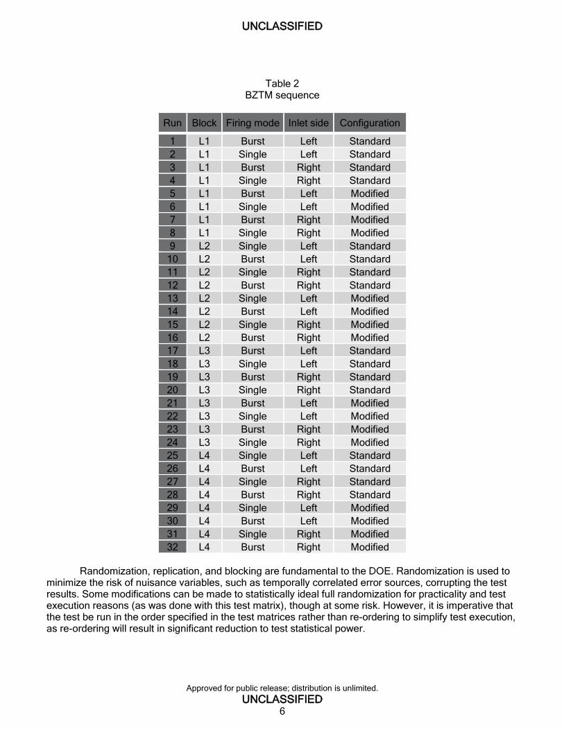
Table 2
BZTM sequence
Run Block Firing mode Inlet side Configuration
1 L1 Burst Left Standard
2 L1 Single Left Standard
3 L1 Burst Right Standard
4 L1 Single Right Standard
5 L1 Burst Left Modified
6 L1 Single Left Modified
7 L1 Burst Right Modified
8 L1 Single Right Modified
9 L2 Single Left Standard
10 L2 Burst Left Standard
11 L2 Single Right Standard
12 L2 Burst Right Standard
13 L2 Single Left Modified
14 L2 Burst Left Modified
15 L2 Single Right Modified
16 L2 Burst Right Modified
17 L3 Burst Left Standard
18 L3 Single Left Standard
19 L3 Burst Right Standard
20 L3 Single Right Standard
21 L3 Burst Left Modified
22 L3 Single Left Modified
23 L3 Burst Right Modified
24 L3 Single Right Modified
25 L4 Single Left Standard
26 L4 Burst Left Standard
27 L4 Single Right Standard
28 L4 Burst Right Standard
29 L4 Single Left Modified
30 L4 Burst Left Modified
31 L4 Single Right Modified
32 L4 Burst Right Modified
Randomization, replication, and blocking are fundamental to the DOE. Randomization is used to
minimize the risk of nuisance variables, such as temporally correlated error sources, corrupting the test results. Some modifications can be made to statistically ideal full randomization for practicality and test execution reasons (as was done with this test matrix), though at some risk. However, it is imperative that the test be run in the order specified in the test matrices rather than re-ordering to simplify test execution, as re-ordering will result in significant reduction to test statistical power.

UNCLASSIFIED
Approved for public release; distribution is unlimited.
UNCLASSIFIED 7
While the measurements of gases CO, HCN, and NH3 as well as the metals Cu, Zn, and Bi are the focus of this study, it is important to consider that the true intent is to measure suppressor blowback. Further, while current small arms propellants have the primary toxic combustion products of CO, HCN, and NH3, future or developmental propellants may contain different toxins. Thus, it is important to tailor the measurements to the toxins that are of interest for the particular system being assessed. In the case of current small arms systems, the toxins of interest are CO, HCN, and NH3 and certain metals, depending on the ammunition being fired.
In addition, in most cases, the full system toxicity (weapon and ammunition) has previously been
measured through the use of TOP 2-2-614, and the ratio of each gaseous constituent is already known (ref. 1). As such, much can be gained simply from measuring the concentration of only a single gas, called an “indicator gas,” and then estimating the concentrations of other gases based on the known ratios to that indicator gas. In the case of current propellants, CO is the most prevalent toxic gas and also the easiest to measure, making it a good choice for an indicator gas. While the addition of a suppressor to the system could have some small effect on the combustion as compared to the unsuppressed system, this effect would be negligible.
All firing was performed to replicate operationally relevant firing. For the M4A1, single shots and
three-round bursts were used. A handheld gas analyzer with the following specifications was used for all gas measurements (ref. 4):
Minimum sampling rate one sample every second (1 Hz)
Electrochemical sensors
CO
Detection range – 0 to 10,000 ppm
Resolution – 5 ppm
Detection limit – 10 ppm
Response time – T90 – 25 se
Sensitivity - +/- 2% of measured value
NH3
Detection range – 0 to 300 ppm
Resolution – 1 ppm
Detection limit – 4 ppm
Response time – T50 – 10 sec
Sensitivity - +/- 3% of measured value
HCN
Detection range – 0 to 50 ppm
Resolution – 0.5 ppm
Detection limit – 3 ppm
Response time – T50 – 10 sec
Sensitivity - +/- 5% of measured value
Sampling pump with flow rate of 0.5 L/min In addition to measurement of gases, metal aerosols were also measured during the CTM. Metals
were collected by passing air from the chamber through an Isopore™ membrane filter with a 0.4-µm pore size produced by Millipore (HTTP type). The filter used a three-piece, 37-mm cassette, with the end cap remover to allow the whole filter face to be exposed to the gas inside the chamber. The air was sucked through the filter at a flow rate of 2 L/min by an AirChek XR5000 pump from SKC, and the sampling time was 3 min. Thus, the total amount of air that passed through the filter was 6 L.

UNCLASSIFIED
Approved for public release; distribution is unlimited.
UNCLASSIFIED 8
Chamber Test Method The objective of the CTM is to measure the direct effect that the addition of a specific suppressor
or muzzle device has on the amount of gases and aerosolized metals blown back toward the operator. The chamber method is performed by measuring the concentration of the total amount of toxic gases (CO, NH3, HCN) and the mass of filtered metallic aerosols blown backward into a chamber of known size with the suppressor or muzzle device in question installed. These gas concentrations and metal aerosol masses are then compared to those blown back by the baseline weapon as well as to the total gases and aerosols produced by the weapon (both blown back and expelled through the muzzle). The chamber is used to isolate whether the total gases or just the blowback gases are being collected. These measurements differ from the BZTM in that all of the blown back gases are measured, regardless of whether these gases reach the operator’s breathing zone. Primarily, the CTM is intended to measure the total difference in gas blown back toward the operator. Firing was done in accordance with table 1. The chamber design follows closely with previous work in toxicity measurements (ref. 5). Test chamber is shown in figure 1.
(a) (b) Total propellant gas Blowback gas only
Figure 1
Chamber with weapon muzzle inside (a) and outside (b)
Since the chamber volume can vary depending on the weapon, scenario, and configuration being tested, reporting only the gas concentration can be misleading when comparing test results. As such, calculating the mass of gas produced will eliminate the effect of chamber volume on the numbers reported. If the number of moles present and the molecular mass of a gas are known, the mass of that gas can be calculated using equation 1. 𝑚𝑔𝑎𝑠 = 𝑛 ×𝑀𝑔𝑎𝑠 (1)
Where:
Mgas is the mass of the gas in grams (g), n is the number of moles, and Mgas is the molecular mass of the gas in grams per mole (g/mol).
UNCLASSIFIED
Approved for public release; distribution is unlimited.
UNCLASSIFIED 9
The ideal gas law can be used to calculate the number of moles (n) of each gas using equation 2.
𝑛 =𝑃×𝑉𝑔𝑎𝑠
𝑅×𝑇 (2)
Where:
P is the pressure in Pascals (Pa), Vgas is the volume of gas in cubic meters (m3), R is the ideal gas constant in Joules per Mole Kelvin (J/mol*K), and T is the temperature in degrees Kelvin (K).
Since the volume of the chamber is variable, and the measured characteristic is concentration of
each gas in ppm, the total volume of each gas can be calculated using equation 3. 𝑉𝑔𝑎𝑠 = 𝑉𝑐ℎ𝑎𝑚𝑏𝑒𝑟 × 𝐶𝑔𝑎𝑠 (3)
Where:
Vchamber is the total volume of the chamber (m3), and Cgas is the concentration of the gas (ppm).
Equation 3 can then be substituted into equation 2 to get equation 4.
𝑛 =𝑃×𝑉𝑐ℎ𝑎𝑚𝑏𝑒𝑟×𝐶𝑔𝑎𝑠
𝑅×𝑇 (4)
Assuming that the gas pressure is approximately atmospheric and that the temperature is room
temperature as well as using the molecular mass of each gas, conversion factors (kgas) can be calculated for each gas in order to calculate the mass of each gas in milligrams (see table 3). Equation 1 can then be simplified to equation 5 to calculate the mass of gas in milligrams. 𝑚𝑔𝑎𝑠 = 𝑘𝑔𝑎𝑠 × 𝐶𝑔𝑎𝑠 × 𝑉𝑐ℎ𝑎𝑚𝑏𝑒𝑟 (5)
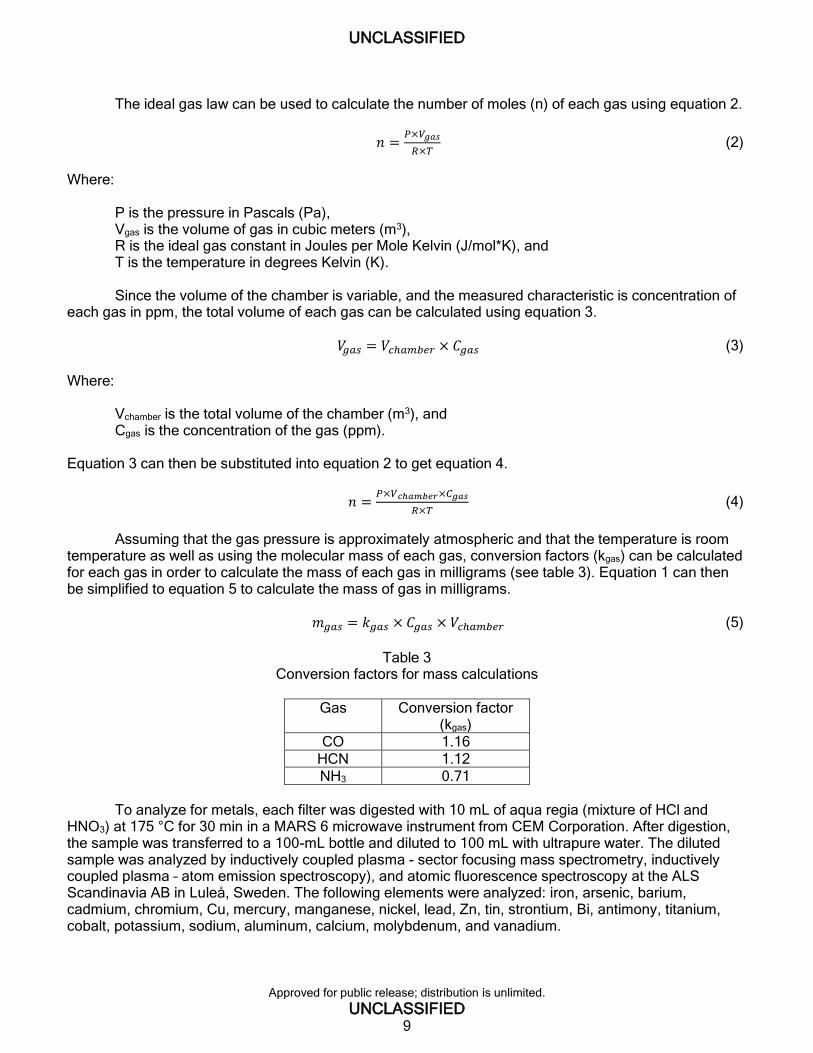
Table 3
Conversion factors for mass calculations
Gas Conversion factor (kgas)
CO 1.16
HCN 1.12
NH3 0.71
To analyze for metals, each filter was digested with 10 mL of aqua regia (mixture of HCl and
HNO3) at 175 °C for 30 min in a MARS 6 microwave instrument from CEM Corporation. After digestion, the sample was transferred to a 100-mL bottle and diluted to 100 mL with ultrapure water. The diluted sample was analyzed by inductively coupled plasma - sector focusing mass spectrometry, inductively coupled plasma – atom emission spectroscopy), and atomic fluorescence spectroscopy at the ALS Scandinavia AB in Luleå, Sweden. The following elements were analyzed: iron, arsenic, barium, cadmium, chromium, Cu, mercury, manganese, nickel, lead, Zn, tin, strontium, Bi, antimony, titanium, cobalt, potassium, sodium, aluminum, calcium, molybdenum, and vanadium.

UNCLASSIFIED
Approved for public release; distribution is unlimited.
UNCLASSIFIED 10
Breathing Zone Test Method The objective of the BZTM is to assess blowback from a system level by measuring
concentrations of toxic gases (CO, NH3, and HCN) in the location of the weapon system operator’s breathing zone during firing with a suppressor, muzzle device, or other accessory of interest. This is accomplished by obtaining gas concentration measurements during various live-fire scenarios at the operator’s breathing zone location in a highly controlled environment. Metals were not filtered or analyzed during the BZTM.
The required test conditions for the BZTM are intended primarily to ensure that the environment is
free of airflow, wind, and obstructions during data collection, as well as to ensure that all other test conditions are controlled to the maximum extent possible. It is critical that the conditions are closely controlled, since the BZTM requires that the blowback gases leave the weapon and begin to mix with the environment before they are measured.
Testing was performed in an indoor range. A 4 by 8-ft sheet of plywood was used as a blast wall
between the muzzle and the rest of the weapon, including the gas block. The blast wall had a hole cut in the center, sized to allow the muzzle to pass through, with any gaps around the barrel minimized or closed with a thick rubber gasket. For firing, the weapon was hard mounted with its muzzle placed through the center of the blast wall. The intent here was to prevent muzzle gases from mixing with blowback gases during measurement.an example of this test setup is shown in figure 2.
Figure 2 Weapon and sampling setup for BZTM, left inlet
A 4-in. air inlet funnel was affixed at the location of the operator’s breathing zone, as measured
from an approximate 50% operator shouldering the subject weapon system. This location was carefully documented. The consistency of placement was critical. Since the air inlet is moved from left to right and vice versa throughout the test, the weapon was marked to ensure that the funnel was placed at the same location prior to each shot. Testing accounted for both left and right-handed operators, per table 2.

UNCLASSIFIED
Approved for public release; distribution is unlimited.
UNCLASSIFIED 11
RESULTS AND DISCUSSION
Chamber Test Method
Gas Measurement Results
The results from the CTM showed consistent and repeatable results. Quantities are reported in milligrams of gas, using equations 1 through 5. Figure 3 shows each data point (shown as points) as well as the mean for each configuration tracked by the blue tracking line. Figures 4 and 5 show the analysis of variance (ANOVA).
Figure 3 Mass of CO produced – all shots
Figure 4 Actual versus predicted mass of CO

UNCLASSIFIED
Approved for public release; distribution is unlimited.
UNCLASSIFIED 12
Figure 5 Summary of fit and ANOVA – CTM
Using statistical methods, it is also possible to look at the interaction between each variable.
Figure 6 shows these interactions.
Figure 6 Interactions between variables – CTM
While the results from the CTM are very repeatable and consistent, they measure only the total
blowback gases and do not give any insight into where those gases go after they leave the chamber and operating group of the weapon. Thus, the blowback was also measured and assessed from the system level, taking into account the directionality of the event and measuring the blowback gases that reach the operator’s breathing zone using the BZTM.

UNCLASSIFIED
Approved for public release; distribution is unlimited.
UNCLASSIFIED 13
Metallic Aerosol Measurement Results
The primary metallic aerosols measured were Cu, Zn, and Bi. The Pb was not measured because lead-free ammunition was used for the test; however, lead would also be of interest in ammunition with lead content in the primer, propellant, or projectile. Results of metallic aerosol measurements for the muzzle inside and outside the chamber, respectively, are shown in figures 7 and 8.
Figure 7 Mass of aerial dust produced – full weapon inside chamber (total dust)
Figure 8 Mass of aerial dust produced – muzzle outside of chamber (blowback dust only)
UNCLASSIFIED
Approved for public release; distribution is unlimited.
UNCLASSIFIED 14
Note that there is an overall reduction of Cu, Zn, and Bi from the full weapon when a suppressor is added. This indicates that these metals are, to some extent, deposited inside the suppressor when a suppressor is installed on the weapon. The Cu, in particular, is significantly reduced when a suppressor is added. This reflects previous testing that has shown a suppressor to gain weight after extended firing.
When the suppressor is placed outside the chamber, Cu is still reduced with a suppressor;
however, Zn remains relatively unchanged and Bi increases. This is likely due to the fact that the primary source of Cu is the projectile, and these particles substantially leave the muzzle during firing. In contrast, the primary source of Bi is the propellant, and when the gases are blown back, the Bi particles that are aerosolized are then blown back as well, increasing the total amount in the blowback gas.
Breathing Zone Test Method
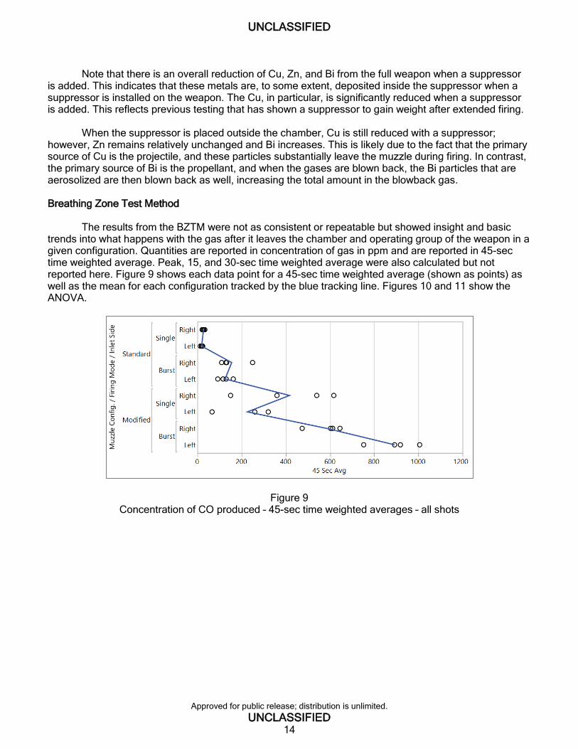
The results from the BZTM were not as consistent or repeatable but showed insight and basic
trends into what happens with the gas after it leaves the chamber and operating group of the weapon in a given configuration. Quantities are reported in concentration of gas in ppm and are reported in 45-sec time weighted average. Peak, 15, and 30-sec time weighted average were also calculated but not reported here. Figure 9 shows each data point for a 45-sec time weighted average (shown as points) as well as the mean for each configuration tracked by the blue tracking line. Figures 10 and 11 show the ANOVA.
Figure 9 Concentration of CO produced – 45-sec time weighted averages – all shots
UNCLASSIFIED
Approved for public release; distribution is unlimited.
UNCLASSIFIED 15
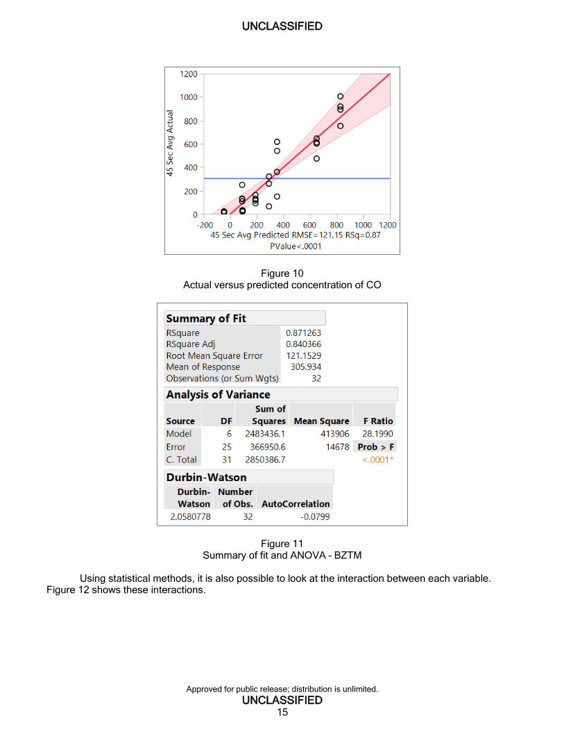
Figure 10 Actual versus predicted concentration of CO
Figure 11 Summary of fit and ANOVA – BZTM
Using statistical methods, it is also possible to look at the interaction between each variable.
Figure 12 shows these interactions.

UNCLASSIFIED
Approved for public release; distribution is unlimited.
UNCLASSIFIED 16
Figure 12 Interactions between variables – BZTM
CONCLUSIONS The addition of the suppressor to the weapon system results in measureable differences of blown
back gases using the methods described. The Breathing Zone Test Method is less repeatable but shows different results that would not be observed with the Chamber Test Method (CTM) alone. Particularly, there are a variety of aftermarket components for weapon systems that are intended to “reduce blowback” when used with a suppressor. Further research has shown that the actual design of these components does not “reduce” blowback at all, but rather, they attempt to redirect the gases away from the operator’s breathing zone. Data has shown that the method can measure differences in concentration at the operator’s face resultant of the use of devices that redirect the gas. This shows that the method can assess directionality, which plays a role in operational impact.
The CTM measures the total blown back gases, regardless of directionality after they leave the
chamber and operating group. Since chambers of different sizes can be used to account for potentially different sized weapons or different amounts of gases produced, CTM results should always be reported in mass of gas in order to eliminate the effect of the chamber volume on the results. This allows appropriate comparison of results between different chambers, regardless of size. The CTM, in contrast to the BZTM, is very repeatable and consistent, but it does not take into account the system level effects, such as other changes to the weapon system to redirect the gas. This indicates that neither method alone is sufficient to assess the true operational impact of the blowback gas, and the best assessment is the combination of both methods.
The metallic dust filtering showed that, in general, metals that are aerosolized from the projectile
are largely deposited within the suppressor. Metals that are aerosolized from the primer and propellant constituents tend to blowback proportionally with the rest of the blowback gases in the system.
Finally, it is important to consider that the order of testing is critical to randomize error. The order
of testing was developed through the use of DOE methods, with the intent to randomize error within the test. The important consideration is that one cannot simply test all of one configuration and setup, then switch to next, and so on. Even if that is easier or quicker, it could result in potential systematic error that must be randomized.

UNCLASSIFIED
Approved for public release; distribution is unlimited.
UNCLASSIFIED 17
REFERENCES
1. TOP 2-2-614, Toxic Hazard Tests for Vehicles and Other Equipment, U.S. Army Combat Systems Test Activity, Weapon Systems Tests, U.S. Army Test and Evaluation Command, Aberdeen Proving Ground, MD, 1995.
2. Center for Disease Control and Prevention, https://www.cdc.gov/niosh/ershdb/emergencyresponsecard_29750038.html (Accessed 04 May 2018), NIOSH data sheet on HCN.
3. Greenberg, M. I. and Vearrier, D., “Metal Fume Fever and Polymer Fume Fever,” Clin. Toxicol. [Online] 2015, 53, https://www.tandfonline.com/doi/full/10.3109/15563650.2015.1013548 (Accessed 30 May 2018).
4. Drager X-AM 5000 Multi-Gas Detector, https://www.draeger.com/Products/Content/x-am-5000-pi-9046318-en.pdf (Accessed 04 May 2018), Drager XAM-5000 data sheet.
5. Dullum, O., Johnsen, A., and Sundem-Eriksen, L., “Emission of Gas and Dust From Small Arms,” Report No. 2015/01728, Norwegian Defence Research Establishment (FFI), Norway, October 2015.


UNCLASSIFIED
Approved for public release; distribution is unlimited.
UNCLASSIFIED 19
DISTRIBUTION LIST
U.S. Army CCDC AC ATTN: FCDD-ACE-K FCDD-ACE-J, A. Jacob FCDD-ACE-QSB, D. Ray FCDD-ACW-WF, D. Cler Picatinny Arsenal, NJ 07806-5000 Defense Technical Information Center (DTIC) ATTN: Accessions Division 8725 John J. Kingman Road, Ste. 0944 Fort Belvoir, VA 22060-6218

UNCLASSIFIED
Approved for public release; distribution is unlimited.
UNCLASSIFIED 20
Kobi O’Malley
Kobi O’Malley
Related Documents


