Standard ECMA-74 6th Edition - December 1999 Standardizing Information and Communication Systems Phone: +41 22 849.60.00 - Fax: +41 22 849.60.01 - URL: http://www.ecma.ch - Internet: [email protected] Measurement of Airborne Noise Emitted by Information Technology and Telecommunications Equipment

Welcome message from author
This document is posted to help you gain knowledge. Please leave a comment to let me know what you think about it! Share it to your friends and learn new things together.
Transcript
Standard ECMA-746th Edi t ion - December 1999
S t a n d a r d i z i n g I n f o r m a t i o n a n d C o m m u n i c a t i o n S y s t e m s
Phone: +41 22 849 .60 .00 - Fax: +41 22 849 .60 .01 - URL: h t tp : / /www.ecma.ch - In ternet : he [email protected]
Measurement of Airborne NoiseEmitted by Information Technologyand Telecommunications Equipment

.
Standard ECMA-746 t h Edi t ion - December 1999
S t a n d a r d i z i n g I n f o r m a t i o n a n d C o m m u n i c a t i o n S y s t e m s
Phone: +41 22 849 .60 .00 - Fax: +41 22 849 .60 .01 - URL: h t tp : / /www.ecma.ch - In ternet : he [email protected]
MB ECMA-074.DOC 10-02-00 14,03
Measurement of Airborne NoiseEmitted by Information Technologyand Telecommunications Equipment

Brief History
ECMA-74 specifies methods for the measurement of airborne noise emitted by information technology andtelecommunications equipment. Hitherto, a wide variety of methods have been applied by individual manufacturers and usersto satisfy particular equipment or application needs. These diverse practices have, in many cases, made comparison of noiseemission difficult. This Standard simplifies such comparisons and is the basis for declaration of the noise emission level ofinformation technology and telecommunications equipment.
In order to ensure accuracy, validity and acceptability, this Standard is based on the basic Standards for determining the soundpower level and for determining the emission sound pressure level at the operator position(s) and bystander position(s).Furthermore, implementation is simplified by conformance with these International Standards.
In many cases free-field conditions over a reflecting plane are realised by hemi-anechoic rooms. These rooms may beparticularly useful during product design to locate and to improve individual contributing noise sources. Reverberation roomsmay be more economical for production control and for obtaining sound power levels for noise emission declaration purposes.
The method for measuring the emission sound pressure level at the operator or bystander positions (based on ISO 11201) isspecified in a separate clause, as this level is not considered to be primary noise emission declaration information. Themeasurements can, however, be carried out in conjunction with those for sound power determination in a free field over areflecting plane.
For comparison of similar equipment it is essential that the installation conditions and mode of operation are the same. Inannex C these parameters are standardized for many categories of equipment.
The first edition of this Standard was issued in September 1981. It was contributed to ISO TC43 and formed the base for ISO7779:1988, first edition. The second edition of ECMA-74 was issued in December 1987. The third edition was issued inDecember 1992 and was submitted to ISO for Fast Track processing as a revision to ISO 7779 in the spring of 1993. Thedocument was balloted by ISO from November 1994 to May 1995 and was approved with 18 of 20 P members in favour and 2of 22 member bodies opposed. The fourth edition was issued in December 1996, taking into account most of the commentsthat accompanied the voting. The fifth edition was issued December 1997 to add a new equipment category – CD- and DVD-ROM drives as C.19.
In the meantime, ISO 7779, second edition has been published, August 1st, 1999. This sixth edition of ECMA-74 has beenadapted to the final wording of new ISO 7779 and also includes additional provisions for CD- and DVD-ROM drives as C.19.
Accepted as the 6th edition of Standard ECMA-74 by the General Assembly of December 1999.

- i -
Table of contents
1 Scope 1
2 References 1
3 Terms and definitions 2
3.1 General definitions 2
3.1.1 basic noise emission standard (B-type standard) 23.1.2 noise test code (C-type standard) 23.1.3 information technology and telecommunications equipment 23.1.4 functional unit 33.1.5 work station 33.1.6 operating mode 33.1.7 idle mode 33.1.8 floor-standing equipment 33.1.9 table-top equipment 33.1.10 wall-mounted equipment 33.1.11 sub-assembly 33.1.12 rack-mounted equipment 33.1.13 standard test table 3
3.2 Acoustical definitions 3
3.2.1 sound pressure, p 33.2.2 time-averaged sound pressure level, LpT 43.2.3 emission sound pressure level, Lp 43.2.4 time-averaged emission sound pressure level, LpeqT 43.2.5 A-weighted impulse sound pressure level, LpAI 43.2.6 C-weighted peak sound pressure level, LpCpeak 43.2.7 sound power, W 43.2.8 reference sound source, 43.2.9 frequency range of interest 4
4 Conformance requirements 5
5 Installation and operating conditions 5
5.1 Equipment installation 5
5.1.1 General 55.1.2 Floor-standing equipment 55.1.3 Table-top equipment 65.1.4 Wall-mounted equipment 65.1.5 Rack-mounted equipment 65.1.6 Hand-held equipment 65.1.7 Sub-assemblies 6
5.2 Input voltage and frequency 65.3 Equipment operation 6
6 Method for determining sound power levels of equipment in reverberation rooms 7
6.1 General 76.2 Measurement uncertainty 76.3 Test environment 8
6.3.1 General 86.3.2 Meteorological conditions 8
6.4 Instrumentation 9
- i i -
6.4.1 General 96.4.2 The microphone and its associated cable 96.4.3 Frequency response of the instrumentation system 96.4.4 Reference sound source 96.4.5 Filter characteristics 96.4.6 Calibration 9
6.5 Installation and operation of equipment: General requirements 96.6 Microphone positions and source locations 9
6.6.1 General 96.6.2 Number of microphone positions, reference source locations and equipment locations 96.6.3 Microphone arrangement 10
6.7 Measurement of sound pressure level 10
6.7.1 General 106.7.2 Measurement duration 106.7.3 Corrections for background noise 10
6.8 Measurement of the sound pressure level of the reference sound source 106.9 Calculation of space/time-averaged band sound pressure level 106.10 Calculation of sound power level 10
6.10.1 Calculation of band sound power levels 106.10.2 Calculation of A-weighted sound power level 10
7 Method for determining sound power levels of equipment under essentially free-fieldconditions over a reflecting plane 13
7.1 General 137.2 Measurement uncertainty 137.3 Test environment 14
7.3.1 General 147.3.2 Meteorological conditions 14
7.4 Instrumentation 14
7.4.1 Microphone and its associated cable 147.4.2 Calibration 14
7.5 Installation and operation of equipment: General requirements 157.6 Measurement surface and microphone positions 15
7.6.1 General 157.6.2 Microphone positions on the measurement surface 16
7.7 Measurement of sound pressure levels 16
7.7.1 General 167.7.2 Measurement duration 16
7.8 Calculation of surface sound pressure level and sound power level 16
8 Method for measuring emission sound pressure levels at defined operator and bystander positions 17
8.1 General 178.2 Measurement uncertainty 178.3 Test environment 17
8.3.1 General 178.3.2 Meteorological conditions 18
8.4 Instrumentation 188.5 Installation and operation of equipment 188.6 Microphone positions 18

- i i i -
8.6.1 At the operator position(s) 188.6.2 At the bystander positions 188.6.3 Microphone orientation 19
8.7 Measurement of sound pressure levels 20
8.7.1 General 208.7.2 Measurement duration 208.7.3 Calculation of A-weighted emission sound pressure levels from band levels 20
8.8 Calculation of the mean emission sound pressure level at the bystander positions 21
9 Information to be recorded and reported 21
9.1 Information to be recorded 21
9.1.1 Equipment under test 219.1.2 Acoustical environment 229.1.3 Instrumentation 229.1.4 Acoustical data 23
9.2 Test report 24
Annex A - Test accessories 27
Annex B - Measurement surfaces 31
Annex C - Installation and operating conditions for specific equipment categories 33
Annex D - Identification of prominent discrete tones 57
Annex E - Detection of impulsive sound pressure levels 61
Annex F - Bibliography 63
.


-1-
1 ScopeThis ECMA Standard specifies procedures for measuring and reporting the noise emission of information technologyand telecommunications equipment. This standard is considered part of a noise test code for this type of equipment,and is based on basic noise emission standards ISO 3741, ISO 3744, ISO 3745 and ISO 11201. The basic emissionquantity is the A-weighted sound power level which may be used for comparing equipment of the same type but fromdifferent manufacturers, or for comparing different equipment.
Three basic noise emission standards for determining the sound power levels are specified in this ECMA Standard inorder to avoid undue restriction on existing facilities and experience. The first basic standard (ISO 3741) specifiescomparison measurements in a reverberation room; the other two (ISO 3744 and ISO 3745) specify measurements inan essentially free field over a reflecting plane. Any one of these three basic noise emission standards may be selectedand shall then be used exclusively according to this Standard when determining sound power levels of a machine.
The A-weighted sound power level is supplemented by the A-weighted emission sound pressure level measured at theoperator position(s) or the bystander positions, based on the basic noise emission standard ISO 11201. This soundpressure level is not a worker's immission rating level, but it may assist in identifying any potential problems thatcould cause annoyance, activity interference, or hearing damage to operators and bystanders.
Methods for determining whether the noise emission includes prominent discrete tones or is impulsive in character arespecified in annexes D and E respectively.
This Standard is suitable for type tests and provides methods for manufacturers and testing laboratories to obtaincomparable results.
The methods specified in this Standard allow the determination of noise emission levels for a unit tested individually.
The procedures may be applied to equipment which emits broad-band noise, narrow-band noise and noise whichcontains discrete-frequency components, or impulsive noise.
The sound power and emission sound pressure levels obtained may serve noise emission declaration and comparisonpurposes (see ECMA-109). They are not to be considered as installation noise immission levels; however they may beused for installation planning (see ECMA TR/27).
If sound power levels obtained are determined for a number of units of the same production series, they can be used todetermine a statistical value for that production series (see ECMA-109).
2 ReferencesECMA-108 Measurement of High-frequency Noise Emitted by Information Technology and
Telecommunication Equipment (3rd edition - December 1996).
ECMA-109 Declared Noise Emission Values of Information Technology and TelecommunicationEquipment (4th edition - December 1996)
ECMA TR/27 Method for the prediction of installation noise levels (2nd edition - June 1999).
ISO 266:1997 Acoustics - Preferred frequencies.
ISO 3741:1999 Acoustics — Determination of sound power levels of noise sources using sound pressure —Precision methods for reverberation rooms.
ISO 3744:1994 Acoustics — Determination of sound power levels of noise sources using sound pressure —Engineering method in an essentially free-field condition over a reflecting plane.
ISO 3745:1977 Acoustics — Determination of sound power levels of noise sources — Precision methods foranechoic and semi-anechoic rooms.
ISO 6926:1999 Acoustics — Requirements for the performance and calibration of reference sound sourcesused for the determination of sound power levels.
ISO 7779:1999 Acoustics — Measurement of airborne noise emitted by information technology andtelecommunications equipment
ISO 9295 Acoustics — Measurement of high-frequency noise emitted by computer and business
- 2 -
equipment.
ISO 9296 Acoustics — Declared noise emission values of computer and business equipment.
ISO 10302 Acoustics — Methods for the measurement of airborne noise emitted by small air-movingdevices.
ISO/IEC 10561:1999 Information technology - Office equipment - Printing devices - Method for measuringprinter throughput - Class 1 and class 2 printers.
ISO 11160:1996 Information technology - Office equipment - Minimum information to be included inspecification sheets - Printers - Part 1: Class 1 and class 2 printers.
ISO 11201:1995 Acoustics — Noise emitted by machinery and equipment — Measurement of emissionsound pressure levels at a work station and at other specified positions — Engineeringmethod in an essentially free field over a reflecting plane.
ISO 11203 Acoustics — Noise emitted by machinery and equipment — Determination of emissionsound pressure levels at a work station and at other specified positions from the sound powerlevel.
ISO 12001:1996 Acoustics - Noise emitted by machinery and equipment - Rules for the drafting andpresentation of a noise test code.
ANSI S1.13:1995 Measurement of Sound Pressure Levels in Air.
IEC 60651 Sound level meters.
IEC 60804 Integrating-averaging sound level meters.
IEC 60942 Electroacoustics — Sound calibrators.
IEC 61260 Electroacoustics — Octave-band and fractional-octave-band filters.
CAUTION:IEC document numbering was recently modified to add 60000 to the original number. This rule applies to not onlynew standards, but also already published ones. Therefore, for instance, IEC 60651 is the identical standard whichhad been referred as to IEC 651 herein.
3 Terms and definitionsFor the purposes of this Standard, the terms and definitions given in ISO 3744 and ISO 11201 and the followingapply.
3.1 General definitions3.1.1 basic noise emission standard (B-type standard)
A standard which specifies procedure for determining the noise emission of machinery and equipment in such away as to obtain reliable, reproducible results with a degree of accuracy.
3.1.2 noise test code (C-type standard)
A standard that is applicable to a particular class, family or type of machinery or equipment which specifies allthe information necessary to carry out efficiently the determination, declaration and verification of the noiseemission characteristics under standardized conditions.
NOTEThis Standard (ECMA-74) together with ECMA-108 and ECMA-109 comprise the noise test code forInformation Technology and Telecommunications Equipment. These Standards are ECMA counterparts of ISO7779, ISO 9295 and ISO 9296, respectively. Both set of noise test codes (ECMA and ISO) are consistent withguidelines specified in ISO 12001[8].
3.1.3 information technology and telecommunications equipment
Equipment for information processing, and components thereof, used in homes, offices, computer installations,telecommunications installations, or similar environments.
- 3 -
3.1.4 functional unit
An entity of physical equipment, which has been allocated an identification number, capable of accomplishing aspecified task.
NOTE 1A functional unit may be supported by a frame or frames and may be self-enclosed or designed to be attached toanother device.
NOTE 2An end-use enclosure in the form of a rack, populated with sub-assemblies or other functional units, may beconsidered a functional unit whether or not it has a separate identification number.
3.1.5 work station
Place in the working environment where an operator performs work.
NOTE 1It does not refer to a computer “workstation”, which denotes a high-performance, single-user computer.
NOTE 2See ISO 11201:1995.
3.1.6 operating mode
Condition in which the equipment being tested is performing its intended function(s).
3.1.7 idle mode
One or more steady-state conditions in which the equipment being tested is energized but is not operating.
3.1.8 floor-standing equipment
Functional unit which is intended to be installed on the floor with or without its own stand.
3.1.9 table-top equipment
Functional unit which has a complete enclosure and which is intended to be installed or used on a table, desk orseparate stand.
3.1.10 wall-mounted equipment
Functional unit which is normally mounted against or in a wall and which does not have a stand of its own.
3.1.11 sub-assembly
Functional unit intended to be installed in another unit or assembled with other units in a single enclosure .
NOTEThe unit may or may not have its own enclosure and identification number.
3.1.12 rack-mounted equipment
One or more sub-assemblies installed in an end-use enclosure.
3.1.13 standard test table
Rigid table having a top surface of at least 0,5 m2 and length of the top plane not less than 0,7 m.
NOTEThe design for the standard test table is shown in annex A.
3.2 Acoustical definitions3.2.1 sound pressure, p
Square root of the time mean square sound pressure during the measurement duration.
NOTE 1Sound pressure is expressed in pascals.
NOTE 2See ISO 3744:1994.
- 4 -
3.2.2 time-averaged sound pressure level, LpT
Sound pressure level of a continuous steady sound that, within a measurement time interval, T, has the samemean-square sound pressure as a sound under consideration which varies with time.
NOTE 1Time averaged sound pressure levels are expressed in decibels.
NOTE 2See ISO 3744:1994.
3.2.3 emission sound pressure level, Lp
Sound pressure level at a specified position near a noise source, measured with a particular time weighting and aparticular frequency weighting, when the source is in operation under specified operating and mountingconditions on a reflecting plane surface, excluding the effects of background noise.
NOTEClause 8 specifies the method for measurement of emission sound pressure level.
3.2.4 time-averaged emission sound pressure level, LpeqT
Emission sound pressure level of a continuous steady sound that, within a measurement time interval, T, has thesame mean square sound pressure as a sound under consideration which varies with time.
( )∫=
T
Tp tp
tp
TL
0 20
2
eq d1
lg10 dB
NOTE 1It is expressed in decibels.
NOTE 2The emission sound pressure level is determined at the specified position(s) required by the test code (i.e. thisStandard, for this specific family of information technology and telecommunications equipment).
NOTE 3See ISO 11201:1995.
3.2.5 A-weighted impulse sound pressure level, LpAI
A-weighted sound pressure level determined with a sound level meter set for the time characteristic I (impulse).
NOTEIt is expressed in decibels.
3.2.6 C-weighted peak emission sound pressure level, LpCpeak
The highest instantaneous value of the C-weighted emission sound pressure level determined over an operationalcycle.
3.2.7 sound power, W
The rate per unit time at which airborne sound energy is radiated by a source.
NOTE 1It is expressed in watts.
NOTE 2In this Standard, it is the time-averaged value of the sound power during the measurement duration.
3.2.8 reference sound source,
Device which is intended for use as a stable source of sound, which has a known, calibrated broad-band soundpower spectrum over the frequency range of interest and which conforms to ISO 6926.
3.2.9 frequency range of interestOctave bands with centre frequencies from 125 Hz to 8 000 Hz.
NOTE 1Under special circumstances the frequency range may have to be extended; see 6.10.2 and table 4.
- 5 -
NOTE 2The 16 kHz octave band shall be included if a preliminary investigation indicates that it may affect the A-weighted sound pressure or sound power levels. However, if the noise in the 16 kHz octave band containsdiscrete tones, then the 16 kHz octave band shall not be included in the determination of the A-weighted levels.The range and centre frequencies of the octave bands are specified in ISO 266 [6]6. See 6.10.2 and table 4 foradditional information.
NOTE 3If the 16 kHz octave band is included in the measurements, the procedures of this Standard may yieldmeasurement uncertainties greater than those stated in 6.2, 7.2 and 8.2.
NOTE 4For equipment which emits sound in the 16 kHz octave band, the procedures specified in ECMA-108 shall beused; see 6.10.2 and table 4.
4 Conformance requirementsMeasurements are in conformance with this ECMA Standard if they meet the following requirements.
a) The measurement procedures, the installation and the operating conditions specified by this Standard are takenfully into account.
b) For the determination of sound power levels, one (and only one) of the methods specified in clause 6 or 7 is used.
c) For measurement of emission sound pressure level at the operator or bystander positions, the method specified inclause 8 is used.
5 Installation and operating conditions5.1 Equipment installation
5.1.1 General
The equipment shall be installed according to its intended use. Installation conditions for many differentcategories of information technology and telecommunications equipment are specified in annex C; these shall befollowed when noise emission declaration information is to be obtained. If the normal installation is unknown orif several possibilities exist, a representative condition shall be chosen and reported.
Care shall be taken to ensure that any electrical conduits, piping, air ducts or other auxiliary equipmentconnected to the equipment being tested do not radiate significant amounts of sound energy into the test room. Ifpracticable, all auxiliary equipment necessary for the operation of the equipment shall be located outside the testroom and the test room shall be free from all objects which may interfere with the measurements.
NOTEIf the equipment is mounted near one or more reflecting planes, the sound power radiated by the equipment maydepend upon its position and orientation. It may be of interest to determine the radiated sound power either forone particular equipment position and orientation or from the average value for several positions andorientations.
5.1.2 Floor-standing equipment
5.1.2.1 Requirements for reverberation rooms
Floor-standing equipment shall be located at least 1,5 m from any wall of the room and no major surfacesshall be parallel to a wall of the reverberation room.
5.1.2.2 Requirements for hemi-anechoic rooms
Floor-standing equipment shall be installed on the reflecting (hard) floor at a sufficient distance (more than2 m, if possible) from the walls, unless otherwise specified in annex C.
The equipment shall be installed in a way which allows access to all sides except the reflecting plane(s). Thedimensions of the reflecting plane(s) shall extend beyond the test object by at least the measurement distance.The requirements for reflection are specified in the note to 7.3.1. The plane(s) shall not contribute to thesound radiation due to their own vibrations.
- 6 -
5.1.2.3 Common requirements
If the equipment being tested consists of several frames bolted together in an installation or is too large fortesting purposes, the frames may be measured separately. In such circumstances, additional covers may berequired for the frames during the acoustical evaluation. These additional covers shall be acousticallycomparable with the other covers on the equipment. If a unit is mechanically or acoustically coupled toanother unit so that the noise emission levels of one are significantly influenced by the other, the equipmentbeing tested shall, where practicable, include all units coupled together in this way.
Floor-standing equipment which is to be installed only in front of a wall shall be placed on a hard floor infront of a hard wall (see the note in 7.3.1). The distance from the wall shall be in accordance with themanufacturer's instructions or as specified in annex C. If such information is not available, the distance shallbe 0,1 m.
5.1.3 Table-top equipment
5.1.3.1 Requirements for reverberation rooms
Table-top equipment shall be placed on the floor at least 1,5 m from any wall of the room unless a table orstand is required for operation according to annex C (e.g. printers which take paper from or stack paper on thefloor). Such equipment shall be placed in the centre of the top plane of the standard test table (see annex A).
5.1.3.2 Requirements for hemi-anechoic rooms
Table-top equipment shall be placed on the floor unless a table or stand is required for operation according toannex C (e.g. printers which take paper from or stack paper on the floor). Such equipment shall be placed inthe centre of the top plane of the standard test table (see annex A). In any case the measurement surfacedefined in 7.6 terminates on the floor.
5.1.4 Wall-mounted equipment
Wall-mounted equipment shall be mounted on a wall of the reverberation room at least 1,5 m from any otherreflecting surface, unless otherwise specified. Alternatively, if operation permits, the equipment may be laidwith its mounting surface on the floor at least 1,5 m (more than 2 m, if possible, in hemi-anechoic rooms) fromany wall of the room.
If the equipment is usually installed by being recessed into a wall or other structure, a representative structureshall be used for mounting during the measurements and described in the test report.
5.1.5 Rack-mounted equipment
Rack-mounted equipment shall be placed in an enclosure which complies with the installation specifications forthe equipment. The location of all units within the enclosure shall be described. The enclosure shall be tested asfloor-standing or table-top equipment. Rack-mounted equipment which does not include, but requires the use of,air-moving equipment (i.e. cooling-fan assemblies) when in operation shall be tested with such equipment, assupplied or recommended by the manufacturer.
Rack-mounted equipment with more than one end-use enclosure may be tested and reported either as individualfunctional units or as a complete system.
5.1.6 Hand-held equipment
Hand-held equipment shall be supported 0,1 m above the reflecting plane by vibration-isolating elements. Thesupports shall not interfere with the propagation of airborne sound.
5.1.7 Sub-assemblies
A sub-assembly shall be supported 0,25 m above the reflecting plane by vibration-isolating elements. Thesupports shall not interfere with the propagation of airborne sound.
5.2 Input voltage and frequencyThe equipment shall be operated at its nominal rated voltage and the rated power line frequency.
Phase-to-phase voltage variations shall not exceed 5 %.
5.3 Equipment operationDuring the acoustical measurements the equipment shall be operated in a manner typical of normal use.
Annex C specifies such conditions for many categories of equipment and shall be followed. However, if the
- 7 -
specified conditions are clearly contrary to the objective of providing uniform conditions closely corresponding tothe intended use of the product, then an additional mode or modes closely related to intended use shall be defined,tested and documented. Any subsequent declaration shall either:
declare both values, indicating that one is based on annex C, and indicating that the other is declared by themanufacturer to be typical use for the intended application; or
declare only the latter, indicating that it is not based on annex C, but is declared by the manufacturer to betypical use for the intended application.
The equipment shall be operated for a sufficient period of time before proceeding with the acoustical test to allowtemperature and other pertinent conditions to stabilize.
The noise shall be measured with the equipment in both idle and the operating modes. If the equipment is designedfor performing different functions, such as manually typing and automatic printing of stored information, or forprinting in different print qualities, unless otherwise specified in annex C, the noise of each individual mode shallbe determined and recorded. For equipment which, in normal functional operation, performs several operatingmodes, such as document insertion, reading, encoding, printing and document eject, and for which a typicaloperation cycle has not been defined in annex C, such a typical cycle shall be defined for the measurements anddescribed in the test report.
In the case of rack-mounted equipment or other equipment in which the operation of several functional units ispossible, the units intended to operate together shall be operated during the test; all other units shall be in idlemode. In the absence of operational guidelines provided by the manufacturer, the unit producing the highestA-weighted sound power level shall be operated together with those other units required for its operation. All otherunits shall be in the idle mode. However, if the operation of the unit which has the highest A-weighted soundpower level occurs only once and less than 5 % of the time during a typical 8 hour working day, the unit producingthe next highest A-weighted sound power level shall be operated together with those other units required for itsoperation; all other units shall be in the idle mode. If none of the operations occurs for more than 5 % of the time ofa typical 8 hour working day, then the aforementioned conditions with the unit with the highest A-weighted soundpower level shall apply.
Some equipment does not operate continuously because of its mechanical design or its mode of operation underprogram control. Long periods may occur during which the equipment is idle. The operating mode measurementsshall not include these idling periods. If it is not possible to operate the equipment continuously during theacoustical evaluation, the time interval during which measurements have to be made shall be described in the testplan, equipment specifications or other documentation.
Some equipment has operational cycles that are too short to allow reliable determination of the noise emissions. Insuch cases, a typical cycle shall be repeated several times.
If the equipment being tested produces attention signals, such as tones or bells, such intermittent sound shall not beincluded in an operating mode. During the acoustical evaluation in the operating mode(s), such attention signalsshall be inoperative or, if this is not possible, they shall be set to a minimum.
NOTEFor certain applications, such signals as well as the maximum response of feedback signals of keyboards may be ofinterest. Such measurements may be made, but they are not part of the methods specified in this Standard.
6 Method for determining sound power levels of equipment in reverberation rooms6.1 General
The method specified in this clause provides a comparison procedure for determining the sound power levelsproduced by information technology and telecommunications equipment in a reverberation room, according to thecomparison method specified in ISO 3741.
It is strongly recommended that the room be qualified in accordance with ISO 3741:1999, annex A. This avoids theneed to determine the number of microphone positions and equipment locations each time equipment is measured.
6.2 Measurement uncertaintyMeasurements carried out in accordance with this method yield standard deviations which are equal to, or less than,
- 8 -
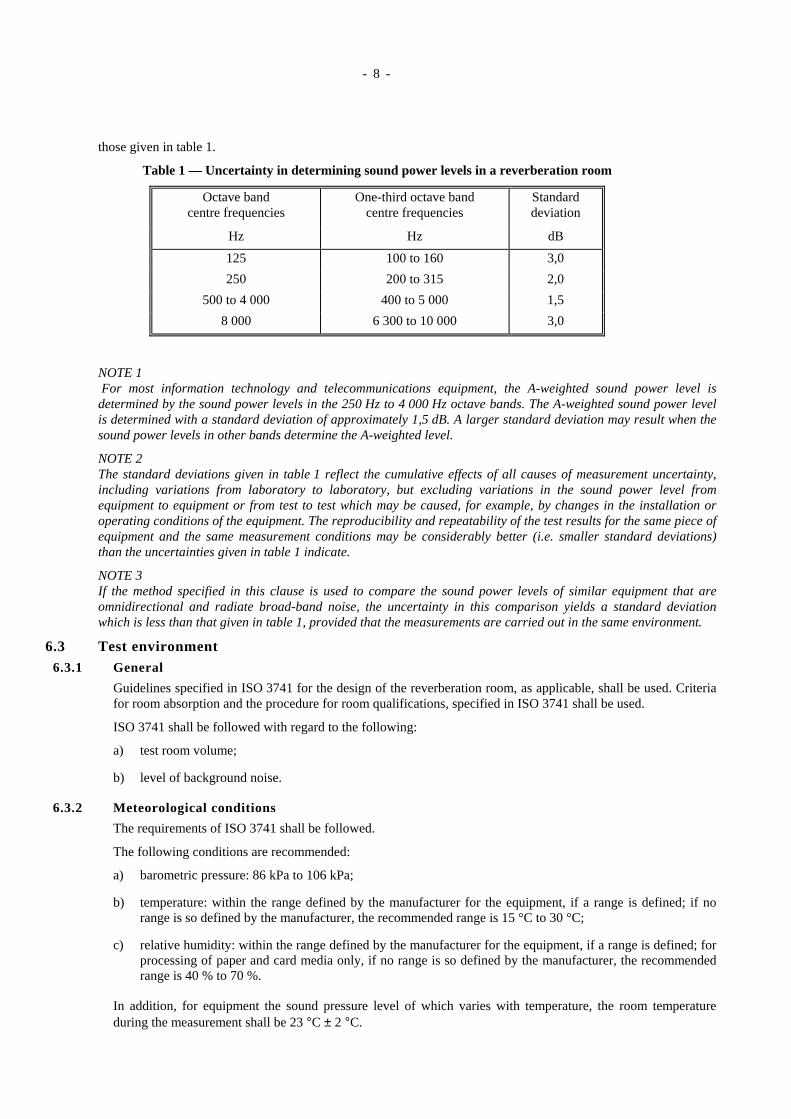
those given in table 1.
Table 1 — Uncertainty in determining sound power levels in a reverberation room
Octave bandcentre frequencies
One-third octave bandcentre frequencies
Standarddeviation
Hz Hz dB
125 100 to 160 3,0
250 200 to 315 2,0
500 to 4 000 400 to 5 000 1,5
8 000 6 300 to 10 000 3,0
NOTE 1 For most information technology and telecommunications equipment, the A-weighted sound power level isdetermined by the sound power levels in the 250 Hz to 4 000 Hz octave bands. The A-weighted sound power levelis determined with a standard deviation of approximately 1,5 dB. A larger standard deviation may result when thesound power levels in other bands determine the A-weighted level.
NOTE 2The standard deviations given in table 1 reflect the cumulative effects of all causes of measurement uncertainty,including variations from laboratory to laboratory, but excluding variations in the sound power level fromequipment to equipment or from test to test which may be caused, for example, by changes in the installation oroperating conditions of the equipment. The reproducibility and repeatability of the test results for the same piece ofequipment and the same measurement conditions may be considerably better (i.e. smaller standard deviations)than the uncertainties given in table 1 indicate.
NOTE 3If the method specified in this clause is used to compare the sound power levels of similar equipment that areomnidirectional and radiate broad-band noise, the uncertainty in this comparison yields a standard deviationwhich is less than that given in table 1, provided that the measurements are carried out in the same environment.
6.3 Test environment6.3.1 General
Guidelines specified in ISO 3741 for the design of the reverberation room, as applicable, shall be used. Criteriafor room absorption and the procedure for room qualifications, specified in ISO 3741 shall be used.
ISO 3741 shall be followed with regard to the following:
a) test room volume;
b) level of background noise.
6.3.2 Meteorological conditions
The requirements of ISO 3741 shall be followed.
The following conditions are recommended:
a) barometric pressure: 86 kPa to 106 kPa;
b) temperature: within the range defined by the manufacturer for the equipment, if a range is defined; if norange is so defined by the manufacturer, the recommended range is 15 °C to 30 °C;
c) relative humidity: within the range defined by the manufacturer for the equipment, if a range is defined; forprocessing of paper and card media only, if no range is so defined by the manufacturer, the recommendedrange is 40 % to 70 %.
In addition, for equipment the sound pressure level of which varies with temperature, the room temperatureduring the measurement shall be 23 °C ± 2 °C.
- 9 -
6.4 Instrumentation6.4.1 General
The requirements of 6.4 as well as the instrumentation requirements of ISO 3741 shall be followed.
Digital integration is the preferred method of averaging (see IEC 60804).
6.4.2 The microphone and its associated cable
The requirements of ISO 3741 shall be followed. In addition, the microphone and its associated cable shall bechosen so that their sensitivity does not change by more than 0,2 dB over the temperature range encounteredduring measurement. If the microphone is moved, care shall be exercised to avoid introducing acoustical orelectrical noise (e.g. from gears, flexing cables, or sliding contacts) that could interfere with the measurements.
6.4.3 Frequency response of the instrumentation system
The requirements of ISO 3741 shall be followed.
6.4.4 Reference sound source
The reference sound source shall meet the requirements specified in ISO 6926 over the frequency range ofinterest.
6.4.5 Filter characteristics
The requirements of a class 1 instrument specified in IEC 61260 shall be followed.
6.4.6 Calibration
During each series of measurements, a sound calibrator with an accuracy of 0,3 dB (class 1 as specified inIEC 60942) shall be applied to the microphone to verify the calibration of the entire measuring system at one ormore frequencies over the frequency range of interest. The compliance of the calibrator shall be verified with therequirements of IEC 60942 once a year, and the compliance of the instrumentation system with the requirementsof IEC 60651 (and IEC 60804 in the case of integrating systems) at least every 2 years in a laboratory makingcalibrations traceable to appropriate standards.
The reference sound source shall be fully calibrated every 2 years according to ISO 6926.
The reference sound source shall be checked annually in accordance with ISO 6926:1990, note 5, to determinewhether or not recalibration of the reference sound source is necessary prior to the 2-year calibration period. Ifchanges in any one-third-octave-band space/time averaged sound pressure level exceed 0,5 dB, then thereference sound source shall be fully calibrated according to ISO 6926 before further use.
The date of the last verification of the compliance with the relevant ISO/IEC standards shall be recorded.
6.5 Installation and operation of equipment: General requirementsSee clause 5.
6.6 Microphone positions and source locations6.6.1 General
The major cause of uncertainty in determining sound power level in a reverberation room is the spatialirregularity of the sound field. The extent of this irregularity and, hence, the effort required to determine theaverage sound pressure level accurately is greater for discrete-frequency sound than for broad-band sound.
It is strongly recommended that the room be qualified in accordance with ISO 3741:1999, annex A. This avoidsthe need to determine the number of microphone positions and equipment locations each time equipment ismeasured.
Otherwise (if the room is not qualified in accordance with Annex A of ISO 3741:1999) the procedure specifiedin clause 8 of ISO 3741:1999 shall be used to determine the minimum number of equipment locations andmicrophone positions, and to determine microphone positions prior to each measurement. The results of theprocedure depend on the presence or absence of significant discrete-frequency components or narrow bands ofnoise in the sound emitted by the source. However, the number of microphone positions and equipmentlocations is usually large.
6.6.2 Number of microphone positions, reference source locations and equipment locations
The requirements of ISO 3741:1999, clause 8, shall be followed.
- 10 -
6.6.3 Microphone arrangement
The requirements of ISO 3741:1999, clause 8, shall be followed.
6.7 Measurement of sound pressure level6.7.1 General
The requirements of ISO 3741 shall be followed, as applicable.
6.7.2 Measurement duration
The requirements below in addition to those of ISO 3741 shall be followed, as applicable.
For equipment which performs repetitive operation cycles (e.g. enveloping machines), the measurement durationshall include at least three operation cycles. For equipment which performs a sequence of varying operationcycles, the measurement duration shall include the total sequence. Annex C specifies additional requirements formany categories of equipment.
6.7.3 Corrections for background noise
The requirements of ISO 3741 shall be followed, as applicable.
6.8 Measurement of the sound pressure level of the reference sound sourceThe requirements below in addition to those of ISO 3741 shall be followed.
For the purposes of determining the sound power level of the equipment by means of reverberant rooms, thisStandard uses exclusively the comparison method specified in ISO 3741. This method has the advantage that it isnot necessary to measure the reverberation time of the test room. The comparison method requires the use of areference sound source with characteristics and calibration in accordance with ISO 6926. The reference soundsource shall be operated, as described in its calibration chart, in the presence of the equipment being tested and inthe presence of the operator, if required to operate the equipment.
6.9 Calculation of space/time-averaged band sound pressure levelThe requirements of ISO 3741 shall be followed.
6.10 Calculation of sound power level6.10.1 Calculation of band sound power levels
The sound power level of the equipment in each octave band or one-third octave band within the frequencyrange of interest is obtained by using the comparison method of ISO 3741.
6.10.2 Calculation of A-weighted sound power level
The A-weighted sound power level, LWA, in decibels, shall be calculated according to ISO 3741:1999, annex F.
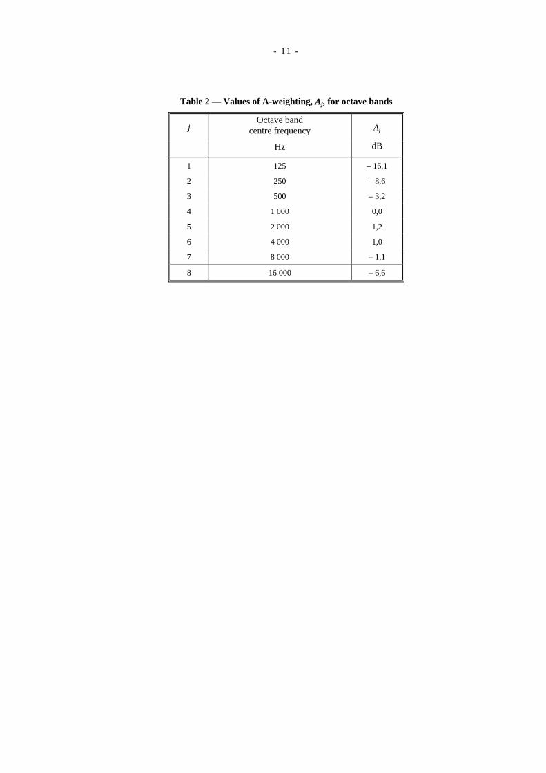
For computations with octave-band data, the Aj values are specified in table 2, and jmax = 7, except as describedbelow.
For computations with one-third-octave-band data, the Aj values are specified in table 3, and jmax = 21, except asdescribed below.
- 11 -
Table 2 — Values of A-weighting, Aj, for octave bands
j Octave band
centre frequency Aj
Hz dB
1 125 – 16,1
2 250 – 8,6
3 500 – 3,2
4 1 000 0,0
5 2 000 1,2
6 4 000 1,0
7 8 000 – 1,1
8 16 000 – 6,6
- 12 -
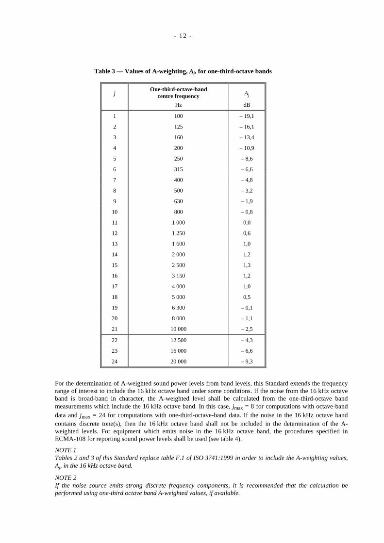
Table 3 — Values of A-weighting, Aj, for one-third-octave bands
jOne-third-octave-band
centre frequency Aj
Hz dB
1 100 – 19,1
2 125 – 16,1
3 160 – 13,4
4 200 – 10,9
5 250 – 8,6
6 315 – 6,6
7 400 – 4,8
8 500 – 3,2
9 630 – 1,9
10 800 – 0,8
11 1 000 0,0
12 1 250 0,6
13 1 600 1,0
14 2 000 1,2
15 2 500 1,3
16 3 150 1,2
17 4 000 1,0
18 5 000 0,5
19 6 300 – 0,1
20 8 000 – 1,1
21 10 000 – 2,5
22 12 500 – 4,3
23 16 000 – 6,6
24 20 000 – 9,3
For the determination of A-weighted sound power levels from band levels, this Standard extends the frequencyrange of interest to include the 16 kHz octave band under some conditions. If the noise from the 16 kHz octaveband is broad-band in character, the A-weighted level shall be calculated from the one-third-octave bandmeasurements which include the 16 kHz octave band. In this case, jmax = 8 for computations with octave-banddata and jmax = 24 for computations with one-third-octave-band data. If the noise in the 16 kHz octave bandcontains discrete tone(s), then the 16 kHz octave band shall not be included in the determination of the A-weighted levels. For equipment which emits noise in the 16 kHz octave band, the procedures specified inECMA-108 for reporting sound power levels shall be used (see table 4).
NOTE 1Tables 2 and 3 of this Standard replace table F.1 of ISO 3741:1999 in order to include the A-weighting values,Aj, in the 16 kHz octave band.
NOTE 2If the noise source emits strong discrete frequency components, it is recommended that the calculation beperformed using one-third octave band A-weighted values, if available.
- 13 -
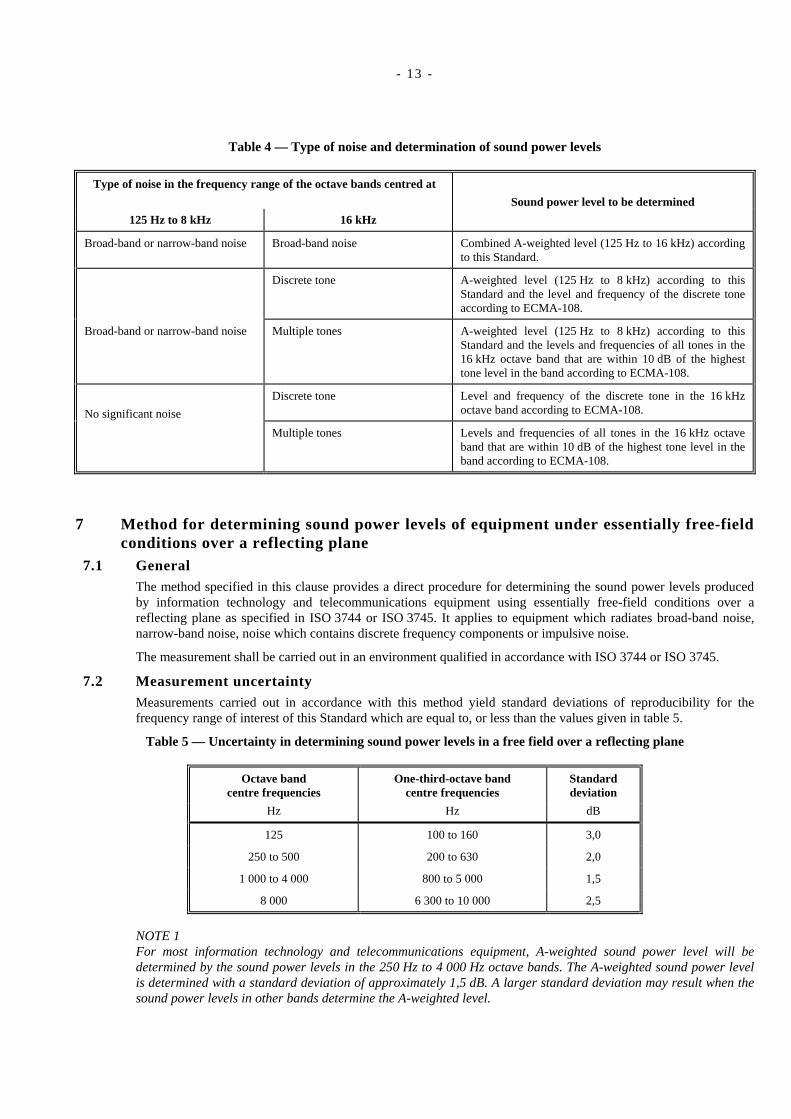
Table 4 — Type of noise and determination of sound power levels
Type of noise in the frequency range of the octave bands centred at
Sound power level to be determined
125 Hz to 8 kHz 16 kHz
Broad-band or narrow-band noise Broad-band noise Combined A-weighted level (125 Hz to 16 kHz) accordingto this Standard.
Discrete tone A-weighted level (125 Hz to 8 kHz) according to thisStandard and the level and frequency of the discrete toneaccording to ECMA-108.
Broad-band or narrow-band noise Multiple tones A-weighted level (125 Hz to 8 kHz) according to thisStandard and the levels and frequencies of all tones in the16 kHz octave band that are within 10 dB of the highesttone level in the band according to ECMA-108.
No significant noise
Discrete tone Level and frequency of the discrete tone in the 16 kHzoctave band according to ECMA-108.
Multiple tones Levels and frequencies of all tones in the 16 kHz octaveband that are within 10 dB of the highest tone level in theband according to ECMA-108.
7 Method for determining sound power levels of equipment under essentially free-fieldconditions over a reflecting plane
7.1 GeneralThe method specified in this clause provides a direct procedure for determining the sound power levels producedby information technology and telecommunications equipment using essentially free-field conditions over areflecting plane as specified in ISO 3744 or ISO 3745. It applies to equipment which radiates broad-band noise,narrow-band noise, noise which contains discrete frequency components or impulsive noise.
The measurement shall be carried out in an environment qualified in accordance with ISO 3744 or ISO 3745.
7.2 Measurement uncertaintyMeasurements carried out in accordance with this method yield standard deviations of reproducibility for thefrequency range of interest of this Standard which are equal to, or less than the values given in table 5.
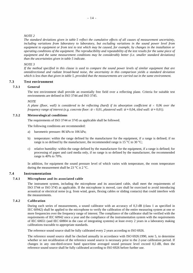
Table 5 — Uncertainty in determining sound power levels in a free field over a reflecting plane
Octave bandcentre frequencies
One-third-octave bandcentre frequencies
Standarddeviation
Hz Hz dB
125 100 to 160 3,0
250 to 500 200 to 630 2,0
1 000 to 4 000 800 to 5 000 1,5
8 000 6 300 to 10 000 2,5
NOTE 1For most information technology and telecommunications equipment, A-weighted sound power level will bedetermined by the sound power levels in the 250 Hz to 4 000 Hz octave bands. The A-weighted sound power levelis determined with a standard deviation of approximately 1,5 dB. A larger standard deviation may result when thesound power levels in other bands determine the A-weighted level.
- 14 -
NOTE 2The standard deviations given in table 5 reflect the cumulative effects of all causes of measurement uncertainty,including variations from laboratory to laboratory, but excluding variations in the sound power level fromequipment to equipment or from test to test which may be caused, for example, by changes in the installation oroperating conditions of the equipment. The reproducibility and repeatability of the test results for the same piece ofequipment and the same measurement conditions may be considerably better (i.e. smaller standard deviations)than the uncertainties given in table 5 indicate.
NOTE 3If the method specified in this clause is used to compare the sound power levels of similar equipment that areomnidirectional and radiate broad-band noise, the uncertainty in this comparison yields a standard deviationwhich is less than that given in table 5, provided that the measurements are carried out in the same environment.
7.3 Test environment7.3.1 General
The test environment shall provide an essentially free field over a reflecting plane. Criteria for suitable testenvironments are defined in ISO 3744 and ISO 3745.
NOTEA plane (floor, wall) is considered to be reflecting (hard) if its absorption coefficient α < 0,06 over thefrequency range of interest (e.g. concrete floor: α < 0,01, plastered wall: α ≈ 0,04, tiled wall: α ≈ 0,01).
7.3.2 Meteorological conditions
The requirements of ISO 3744 or 3745 as applicable shall be followed.
The following conditions are recommended:
a) barometric pressure: 86 kPa to 106 kPa;
b) temperature: within the range defined by the manufacturer for the equipment, if a range is defined; if norange is so defined by the manufacturer, the recommended range is 15 °C to 30 °C;
c) relative humidity: within the range defined by the manufacturer for the equipment, if a range is defined; forprocessing of paper and card media only, if no range is so defined by the manufacturer, the recommendedrange is 40% to 70%.
In addition, for equipment the sound pressure level of which varies with temperature, the room temperatureduring the measurement shall be 23 °C ± 2 °C.
7.4 Instrumentation7.4.1 Microphone and its associated cable
The instrument system, including the microphone and its associated cable, shall meet the requirements ofISO 3744 or ISO 3745 as applicable. If the microphone is moved, care shall be exercised to avoid introducingacoustical or electrical noise (e.g. from wind, gears, flexing cables or sliding contacts) that could interfere withthe measurements.
7.4.2 Calibration
During each series of measurements, a sound calibrator with an accuracy of 0,3 dB (class 1 as specified inIEC 60942) shall be applied to the microphone to verify the calibration of the entire measuring system at one ormore frequencies over the frequency range of interest. The compliance of the calibrator shall be verified with therequirements of IEC 60942 once a year and the compliance of the instrumentation system with the requirementsof IEC 60651 (and IEC 60804 in the case of integrating systems) at least every 2 years in a laboratory makingcalibrations traceable to appropriate standards.
The reference sound source shall be fully calibrated every 2 years according to ISO 6926.
The reference sound source shall be checked annually in accordance with ISO 6926:1990, note 5, to determinewhether or not recalibration of the reference sound source is necessary prior to the 2-year calibration period. Ifchanges in any one-third-octave band space/time averaged sound pressure level exceed 0,5 dB, then thereference sound source shall be fully calibrated according to ISO 6926 before further use.
- 15 -
The date of the last verification of the compliance with the relevant ISO/IEC standards shall be recorded.
7.5 Installation and operation of equipment: General requirementsSee clause 5.
7.6 Measurement surface and microphone positions7.6.1 General
Except as specified in annex B, the requirements of ISO 3744 or ISO 3745 shall be followed as applicable. Forinformation technology and telecommunications equipment, the preferred measurement surfaces arehemispherical and are described in annex B of ISO 3744:1994. The conditions of clause 5 above shall howeverbe followed. The number and location of the microphone positions shall be as specified in annexes B or C ofISO 3744:1994, or in annexes C or D of ISO 3745:1977, as applicable, except as specified in annex B of thisStandard.
NOTE 1Hemispherical measurement surfaces require a minimum radius of 1 m in accordance with ISO 3744 andISO 3745. In some cases, for example when equipment sound power levels are relatively low, it may be helpfulto select the parallelepiped measurement surface which permits measurement distances, d, as small as 0,25 m.
In order to facilitate the location of the microphone positions, a hypothetical reference surface is defined. Thisreference surface is the smallest possible rectangular box (i.e. rectangular parallelepiped) that just encloses theequipment and terminates on the reflecting plane(s). It has length l1, width l2 and height l3. Elements protrudingfrom the equipment being tested which are unlikely to contribute to the noise emission may be disregarded. Themicrophone positions lie on the measurement surface, a hypothetical surface of area S which envelops theequipment as well as the reference box and terminates on the reflecting plane.
The location of the equipment being tested, the measurement surface and the microphone positions are definedby a co-ordinate system with horizontal axes x and y in the ground plane parallel to the length and width of thereference box and with the vertical axis z passing through the geometric centre of the reference box. The x axispoints towards the front of the equipment. The position of the origin for the coordinates of the microphonepositions is specified as follows:
a) for floor-standing equipment: on the floor in the centre of the plane of the reference box which is coplanarwith the room floor;
b) for table-top equipment on a table or on the floor: same conditions as for floor-standing equipmentdescribed in a);
c) for wall-mounted equipment: in the centre of that plane of the reference box which is coplanar with themounting surface;
d) for rack-mounted equipment: same conditions as for floor-standing equipment described in a);
e) for hand-held equipment: same conditions as for floor-standing equipment described in a);
f) for sub-assemblies: same conditions as for floor-standing equipment described in a);
NOTE 2For fixed microphone arrays, either a single microphone may be moved from one position to the nextsequentially or a number of fixed microphones may be used and their outputs sampled sequentially orsimultaneously. Alternatively, a continuous microphone traverse may be used as described in annex B ofISO 3744:1994.
Near air exhausts, the microphone position shall be selected in such a way that the microphone is not exposed tothe air stream, otherwise a windscreen shall be used.
The microphones shall be oriented in such a way that the angle of sound incidence is the same as the angle forwhich the microphone has the most uniform frequency response as specified by the manufacturer. For mostpractical cases this will be an orientation towards the approximate geometric centre of the equipment.

- 16 -
7.6.2 Microphone positions on the measurement surface
Except as stated immediately below, microphone positions shall meet the requirements of ISO 3744 orISO 3745, as applicable, including the requirements for additional microphone positions and for reduction in thenumber of microphone positions, where applicable.
When the equipment emits prominent discrete tones, microphone positions given in annex B shall be used. Iflarge equipment is to be measured in small rooms providing free-field conditions over a reflecting plane inaccordance with ISO 3745, it may be easier to place the equipment not in the centre of the room but closer to acorner and to arrange the microphone positions in the free field of the room. The equipment should be turnedaround so that noise radiation from the different sides of the machine can be determined sequentially.
7.7 Measurement of sound pressure levels7.7.1 General
Measurements of the sound pressure levels shall be carried out in accordance with ISO 3744 or ISO 3745 andwith the following requirements.
Measurements of the sound pressure level shall be carried out at the microphone positions specified in 7.6 withA-weighting and/or for each frequency band within the frequency range of interest, if required. The followingdata shall be obtained:
the A-weighted sound pressure levels and/or the band sound pressure levels, for the specified modes ofoperation of the equipment;
the A-weighted sound pressure levels and/or the band sound pressure levels of the background noise(including noise from support equipment).
When using a sound level meter, the person reading the meter shall not disturb the sound field at themicrophone.
7.7.2 Measurement duration
The requirements below, in addition to those of ISO 3744, shall be followed, as applicable.
For equipment which performs repetitive operation cycles (e.g., enveloping machines), the measurementduration shall include at least three cycles. For equipment which performs a sequence of varying cycles, themeasurement duration shall include the total sequence. Annex C specifies additional requirements for manytypes of equipment.
When the measurement duration over the total sequence of operation cycles exceeds 40 s, time and spatialaveraging may be performed in combination by sampling all microphones in sequence at least ten times anddwelling at each microphone each time for at least 4 s. This may be accomplished, for example, with ninemicrophones, a multiplexer and an integrating analyser or integrating-averaging sound level meter. Sampling fora period longer than 4 s should be carried out, as required, to ensure that 4 s of data at that microphone positionare actually acquired and that any settling period (due to exponential averaging, for example) is excluded.
Dwell duration and number of samples shall be the same for all microphones.
7.8 Calculation of surface sound pressure level and sound power levelCalculation of sound pressure level averaged over the measurement surface shall be according to clause 8 ofISO 3744:1994. This includes corrections for background noise and test environment. For hemi-anechoic roomsmeeting the requirements of ISO 3745, no K2 correction is applied.
For the determination of A-weighted sound pressure levels from band levels, this Standard extends the frequencyrange of interest to include the 16 kHz octave band under some conditions. If the noise from the 16 kHz octaveband is broad-band in character, the A-weighted level shall be calculated from the one-third-octave bandmeasurements which include the 16 kHz octave band. If the noise in the 16 kHz octave band contains discretetone(s), then the 16 kHz octave band shall not be included in the determination of the A-weighted levels. Forequipment which emits noise in the 16 kHz octave band, the procedures specified in ECMA-108 for reportingsound power levels shall be used (see table 4 of this Standard).
Tables 2 and 3 of this Standard replace table 2 of ISO 3744:1994 in order to include the A-weighing values Aj inthe 16 kHz octave band.
- 17 -
If the noise source emits strong discrete frequency components, it is recommended that the calculation beperformed using one-third-octave band A-weighted levels, if available.
8 Method for measuring emission sound pressure levels at defined operator andbystander positions
8.1 GeneralThe method specified in this clause defines the conditions of measurement of emission sound pressure levels at thework station (operator) position and at the bystander position(s) in an essentially free field over a reflecting plane inaccordance with ISO 11201. The method is applicable to equipment which radiates broad-band noise, narrow-bandnoise, noise which contains discrete frequency components, or impulsive noise.
This method of measurement does not apply to sub-assemblies. However, where emission sound pressure levels aredesired for sub-assemblies, the method specified in ISO 11203 to determine an emission sound pressure level valuefrom a previously measured sound power level using Q = Q1 = 8 dB shall be followed. This value of Q correspondsto a radial distance of 1 m from a small sub-assembly radiating hemispherically; for uniformity this value of Q isapplicable to all sub-assemblies. Optionally, actual emission sound pressure levels may be measured at operator orbystander positions as described below.
NOTEThe methods for determining whether the noise at the operator position or at the bystander positions containsprominent discrete tones and/or is impulsive in character are specified in annex D and annex E, respectively.These methods are applicable to equipment and sub-assemblies.
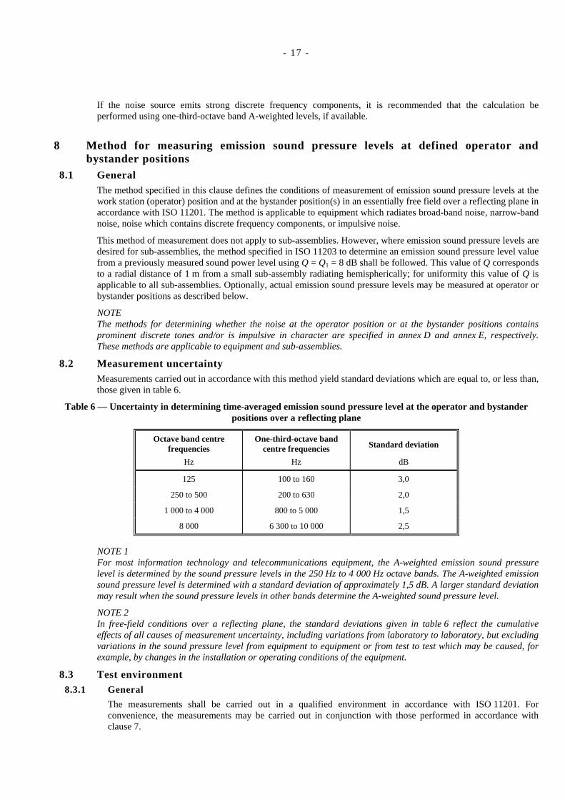
8.2 Measurement uncertaintyMeasurements carried out in accordance with this method yield standard deviations which are equal to, or less than,those given in table 6.
Table 6 — Uncertainty in determining time-averaged emission sound pressure level at the operator and bystanderpositions over a reflecting plane
Octave band centrefrequencies
One-third-octave bandcentre frequencies Standard deviation
Hz Hz dB
125 100 to 160 3,0
250 to 500 200 to 630 2,0
1 000 to 4 000 800 to 5 000 1,5
8 000 6 300 to 10 000 2,5
NOTE 1For most information technology and telecommunications equipment, the A-weighted emission sound pressurelevel is determined by the sound pressure levels in the 250 Hz to 4 000 Hz octave bands. The A-weighted emissionsound pressure level is determined with a standard deviation of approximately 1,5 dB. A larger standard deviationmay result when the sound pressure levels in other bands determine the A-weighted sound pressure level.
NOTE 2In free-field conditions over a reflecting plane, the standard deviations given in table 6 reflect the cumulativeeffects of all causes of measurement uncertainty, including variations from laboratory to laboratory, but excludingvariations in the sound pressure level from equipment to equipment or from test to test which may be caused, forexample, by changes in the installation or operating conditions of the equipment.
8.3 Test environment8.3.1 General
The measurements shall be carried out in a qualified environment in accordance with ISO 11201. Forconvenience, the measurements may be carried out in conjunction with those performed in accordance withclause 7.
- 18 -
CAUTION:Installation conditions are not always identical between clause 7 and clause 8.
8.3.2 Meteorological conditions
The environmental conditions shall be as specified in 7.3.2.
8.4 InstrumentationInstrumentation shall meet the provisions of ISO 11201 and the additional requirements of 7.4 of this Standard.
8.5 Installation and operation of equipmentEquipment shall be installed and operated in accordance with the requirements of clause 5 except that table-topequipment shall be installed centred on a standard test table. Any table-top equipment combination which includesa keyboard shall be installed such that the smallest rectangle in the plane of the table and encompassing thekeyboard and other units is centred on the top of the standard test table. Any table-top equipment combinationwhich normally is operated with a detachable keyboard but which is tested without the keyboard shall be centredon the test table as in the preceding sentence, as if the keyboard were present.
For optional measurement of sub-assemblies intended for use in table-top products, install the sub-assembly in thecentre of a standard test table and isolated from the surface by three or four elastomeric feet, approximately 12 mmhigh. For optional measurement of sub-assemblies intended for use in other enclosures or racks, install thesub-assembly as specified in 5.1.7.
8.6 Microphone positionsNOTE These requirements are in accordance with, but more specific than, those of ISO 11201.
8.6.1 At the operator position(s)
One or more operator positions shall be specified for equipment which requires operator attention while in theoperating mode.
For equipment which is operated from a standing position, the microphone shall be located 1,50 m ± 0,03 mabove the floor (see figure 1, position P1).
For equipment which is operated from a seated position, the microphone shall be located 1,20 m ± 0,03 m abovethe floor (see figure 1, position P2 or P3).
The horizontal distance from the reference box shall be 0,25 m ± 0,03 m unless this distance is notrepresentative of the operator position; in the latter case the representative operator position shall be describedand shall be used.
For table-top equipment which normally has a detachable keyboard and which is tested without the keyboard(e.g. a desk-top personal computer or a video display unit that is tested without a keyboard), the distance fromthe front end of the reference box, for purposes of determining the operator position, shall be 0,50 m ± 0,03 m infront of such equipment (see figure 1, position P4).
For optional measurement of sub-assemblies intended for use in equipment with a defined operator position, thisoperator position shall be used for the sub-assembly measurement.
NOTE 1During this measurement the operator should be absent, if possible, or move aside, so that he/she can stilloperate the equipment but does not significantly disturb the sound field around the microphone.
NOTE 2If sound pressure level at the operator position is measured on operator-attended equipment, then measurementof sound pressure level at the bystander position is not required.
8.6.2 At the bystander positions
For equipment which does not require operator attention while in the operating mode, an operator position neednot be specified. In this case, at least four bystander positions shall be selected and specified.
The bystander positions shall be 1,00 m ± 0,03 m away from the projection of the reference box on thehorizontal plane 1,50 m ± 0,03 m above the floor. The four preferred bystander positions are centred at the front,
- 19 -
rear, right and left sides of the equipment. If the length of any side of the reference box exceeds 2,0 m,additional bystander positions at 1,0 m intervals should be used. For wall-mounted equipment or for equipmentplaced against the wall, the three preferred bystander positions are centred at the front, right and left sides of themeasurement surfaces.
For optional measurement of sub-assemblies intended for use in equipment which does not require operatorattention while in the operating mode, the provisions of the preceding two paragraphs apply.
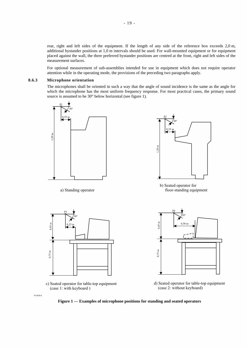
8.6.3 Microphone orientation
The microphones shall be oriented in such a way that the angle of sound incidence is the same as the angle forwhich the microphone has the most uniform frequency response. For most practical cases, the primary soundsource is assumed to be 30° below horizontal (see figure 1).
97-0035-A
0,25 m
1,5
0m
P1
30°
a) Standing operatorb) Seated operator for
floor-standing equipment
c) Seated operator for table-top equipment(case 1: with keyboard )
d) Seated operator for table-top equipment(case 2: without keyboard)
0,25 m
1,2
0m
P2
30°
0,25 m
0,7
5m
0,4
5m
P3
30°
0,50 m
0,7
5m
0,4
5m
P4
30°
Figure 1 — Examples of microphone positions for standing and seated operators
- 20 -
8.7 Measurement of sound pressure levels8.7.1 General
Measurements of the emission sound pressure level required by this clause shall be carried out at themicrophone positions specified in 8.6 with A-weighting and/or for each frequency band within the frequencyrange of interest. The following data shall be obtained:
the A-weighted sound pressure levels and/or the band sound pressure levels, for the specified modes ofoperation of the equipment;
the A-weighted sound pressure levels and/or the band sound pressure levels of the background noise(including noise from support equipment).
When using a sound level meter, the person reading the meter shall not disturb the sound field at themicrophone.
Should spatial fluctuations occur, due to interferences or standing waves, it is recommended that the microphonebe moved by approximately 0,1 m in a vertical plane around the nominal measurement position, and the averagesound pressure level be recorded.
NOTE 1The methods for determining whether the emission sound pressure at the operator position or at the bystanderpositions contains discrete tones and/or is impulsive in character are specified in annex D and annex E,respectively.
Measurements of the C-weighted peak emission sound pressure level, LpCpeak, shall be carried out at themicrophone positions specified in 8.6 if any of the LpCpeak levels at the specified positions exceeds 120 dB.
NOTE 2Some regulations require declaration of C-weighted peak emission sound pressure levels greater than 130 dB.Contemporary information technology and telecommunications equipment is unlikely to emit C-weighted peakemission sound pressure levels (LpCpeak) greater than 120 dB, which is set in this Standard as a conservativethreshold above which measurement and reporting are required.
8.7.2 Measurement duration
The measurement duration shall be as specified in 7.7.2.
8.7.3 Calculation of A-weighted emission sound pressure levels from band levels
A-weighted emission sound pressure levels LpA may be measured directly or determined from the followingequation:
[ ]∑ +=max
1=
0,1A 10lg10
j
j
ALp
jpjL
dB (1)
where
Lpj is the level in the j-th octave or one-third-octave band;
Aj is the j-th value of A-weighting from table 2 or 3.
For the determination of A-weighted emission sound pressure levels from band levels, this Standard extends thefrequency range of interest to include the 16 kHz octave band under some conditions. If the noise from the16 kHz octave band is broad-band in character, the A-weighted level shall be calculated from the one-third-octave band measurements which include the 16 kHz octave band. If the noise in the 16 kHz octave bandcontains discrete tone(s), then the 16 kHz octave band shall not be included in the determination of the A-weighted levels. For equipment which emits noise in the 16 kHz octave band, the procedures specified inECMA-108 for reporting sound power levels shall be used (see table 4).
NOTE If the noise source emits strong discrete frequency components, it is recommended that the calculation beperformed using one-third-octave-band A-weighted levels, if available.
dB
- 21 -
8.8 Calculation of the mean emission sound pressure level at the bystander positions
If bystander positions are defined, the mean A-weighted emission sound pressure level, LpA, and the mean bandemission sound pressure levels, Lp, if required, at bystander positions defined in 8.6.2, shall be calculated asspecified in the following formula:
dB101
lg101
1,0
= ∑
=
N
i
Lp
pi
NL (2)
where
Lp is the band emission sound pressure level averaged over the bystander positions, in decibels(reference: 20 µPa);
Lpi is the band emission sound pressure level resulting from measurement at the i-th bystander position, indecibels (reference: 20 µPa);
N is the number of bystander positions.
For A-weighted emission sound pressure level, the symbols Lp and Lpi are replaced by LpA and LpAi.
9 Information to be recorded and reported9.1 Information to be recorded
The information specified in 9.1.1 to 9.1.5 shall be recorded, when applicable. In addition, any deviation from anyrequirement in this noise test code or from the basic standards upon which it is based shall be recorded togetherwith the technical justification for such deviation.
All requirements for recording and reporting specified in the basic standards are also requirements of this Standard.That is, the requirements below are necessary but not sufficient.
9.1.1 Equipment under test
The following information shall be recorded:
a) a description of the equipment under test (including main dimensions; name, model and serial number ofeach unit; name, model and serial number of noise producing components and sub-assemblies in the unitunder test);
b) a complete description of the idle and operating modes, including operating speed, data medium used andthe test programme in terms that are meaningful for the type of equipment being tested;
c) a complete description of the installation and mounting conditions;
d) the location of the equipment in the test environment;
e) the location and functions of an operator, if present;
f) the nominal power line frequency, in hertz (e.g. 50 Hz), and the measured power line voltage, in volts;
g) a sample of typical hardcopy output of the product being tested, when applicable, should be filed as part ofthe recorded data;
h) a statement as to whether the noise emission depends on room temperature, if known.
The following information is recommended to be recorded; a tape recording is recommended as follows.
For each operating mode, for the operator position (if defined), otherwise for the bystander position (if defined)with the highest A-weighted emission sound pressure level, a high quality magnetic tape recording may bemade, of at least 1 min duration, annotated by voice on the second track with the name of the product, the testmode, the microphone position, and the A-weighted sound pressure level of the signal. Dolby or other magnetictape noise reduction features SHALL NOT be used. This Standard does not require that a calibration signal berecorded. The bias used in recording shall be noted on the cassette.
- 22 -
9.1.2 Acoustical environment
The following information shall be recorded.
a) If the sound power is determined in accordance with clause 6 (ISO 3741):
1) a description of the test room, including dimensions, shape, surface treatment of the walls, ceiling andfloor; a sketch showing location of source and room contents;
2) a description of diffusers, or rotating vanes, if any;
3) qualification of reverberation room in accordance with annex A of ISO 3741:1999;
4) the air temperature, in degrees Celsius, relative humidity as a percentage, and barometric pressure inkilopascals.
b) If the sound power is determined in accordance with clause 7 (ISO 3744 or ISO 3745):
1) a description of the acoustical environment, if indoors, the size and acoustic characteristics of theroom, including absorptive properties of the walls, ceiling and floor; a sketch showing the location ofthe equipment under test;
2) environmental correction K2 resulting from the acoustical qualification of test environment inaccordance with annex A of ISO 3744:1994, unless the environment has been qualified in accordancewith ISO 3745; in the case of compliance with ISO 3745, this fact should be stated;
3) the air temperature in degrees Celsius, relative humidity as a percentage, and barometric pressure inkilopascals.
c) For emission sound pressure levels at the operator and bystander positions in accordance with clause 8(ISO 11201):
NOTE 1The type of information below is the same as for sound power determination, just described, but the valuesmay differ from those recorded for sound power. If the information recorded for sound powerdetermination in accordance with the preceding paragraph is applicable here, it is sufficient to so note inthe test file.
1) a description of the acoustical environment, if indoors, the size and acoustic characteristics of theroom, including absorptive properties of the walls, ceiling and floor; a sketch showing the location ofthe equipment under test;
2) environmental correction K2 resulting from the acoustical qualification of test environment inaccordance with ISO 3744:1994, annex A;
NOTE 2Environmental correction K2 is not to be used to modify the measured values, but is included as part of thetest record as in indication of the quality of the measurement.
3) the air temperature in degrees Celsius, relative humidity as a percentage, and barometric pressure inkilopascals.
9.1.3 Instrumentation
The following information shall be recorded:
a) equipment used for the measurements, including name, type, serial number and manufacturer;
b) bandwidth of frequency analyser;
c) frequency response of the instrumentation system;
d) method used for daily checking of the calibration of the microphones and other system components;
e) the date and place of annual calibration;

- 23 -
f) the test method used for determining;
1) the band space/time-averaged sound pressure level in accordance with clause 5 of ISO 3741:1999; or
2) the surface sound pressure level in accordance with clause 8 of ISO 3744:1994; and
3) the mean value of the emission sound pressure level at the operator or bystander positions in accordancewith clause 8 of ISO 11201:1995; and
g) impulsive parameter ∆LI, in decibels, in accordance with annex E, if measured.
9.1.4 Acoustical data
The following information shall be recorded.
a) If the sound power is determined according to clause 6 (ISO 3741):
1) location and orientation of the microphone traverse (path) or array (a sketch should be included ifnecessary);
2) the corrections, if any, in decibels, applied in each frequency band for the frequency response of themicrophone, frequency response of the filter in the passband, background noise, etc.;
3) the values of the difference between the sound power and sound pressure levels produced by thereference sound source (LWr – Lpr), in decibels, as a function of frequency;
4) the band pressure level readings, in decibels, to at least the nearest 0,1 dB (preferred), 0,5 dB(required) for the calculations in accordance with ISO 3741;
5) the sound power levels in decibels (reference: 1 pW) in octave and/or one-third-octave bands,tabulated or plotted to the nearest 0,1 dB (preferred), 0,5 dB (required);
6) the A-weighted sound power level in decibels (reference: 1 pW) rounded to the nearest 0,1 dB(preferred), 0,5 dB (required);
7) the date, time and place that the measurements were carried out, and the name of the person whocarried out the measurements.
b) If the sound power level is determined according to clause 7 (ISO 3744 or ISO 3745):
1) the shape of the measurement surface, the measurement distance, the location and orientation ofmicrophone positions or paths; if traversing microphones were used, the maximum traversing speedalong a path and microphone orientation shall be reported;
2) the area, S, of the measurement surface;
3) the corrections, if any, in decibels, applied in each frequency band for the frequency response of themicrophone, and frequency response of the filter in the passband;
4) the background noise correction K1 (A-weighted or in frequency bands) for the surface sound pressurelevels;
5) the background noise level measured at each point and the average background sound pressure levels;
6) the environmental corrections K2 (A-weighted or in frequency bands) and the method by which it wasdetermined in accordance with one of the procedures of annex A of ISO 3744:1994;
7) the A-weighted surface sound pressure level and the band surface-averaged sound pressure level Lpf,for each frequency band of interest, rounded to at least the nearest 0,1 dB (preferred), 0,5 dB(required);
- 24 -
8) the sound pressure levels Lpi (A-weighted or in frequency bands ) at each measuring point i;
9) the A-weighted sound power level LWA, and the band sound power level LW, for each frequency bandof interest, rounded to the nearest 0,1 dB (preferred), 0,5 dB (required);
10) the date, time and place that the measurements were carried out, and the name of the person whocarried out the measurements.
c) For emission sound pressure levels at the operator and bystander positions according to clause 8(ISO 11201):
1) the measurement positions and microphone orientations (preferably including a sketch);
2) if an operator position is defined according to 8.6.1, the A-weighted emission sound pressure levelLpA, the band emission sound pressure levels if required, and the C-weighted peak emission soundpressure level LpCpeak if greater than 120 dB, measured at the operator position(s) for both the idle andoperating modes, in decibels, rounded to the nearest 0,1 dB (preferred) 0,5 dB (required);
3) if bystander positions are defined according to 8.6.2, the A-weighted emission sound pressure levels atthe bystander positions, if required, the mean A-weighted emission sound pressure level LpA, and themean band emission sound pressure levels, if required, calculated according to 8.8 and the C-weightedpeak emission sound pressure level LpCpeak if greater than 120 dB (see note 2 in 8.7.1) at the bystanderposition with the highest A-weighted emission sound pressure level for both the idle and operatingmodes, in decibels rounded to the nearest 0,1 dB preferred (0,5 dB required);
4) optionally, the impulsive parameter ∆LI, in decibels, if ∆LI > 3 dB, in accordance with the procedureoutlined in annex E;
5) optionally, the frequency, in hertz, of any prominent discrete tones identified in accordance with theprocedure of annex D and the quantity (Lt – Ln), in decibels, associated with that prominent discretetone;
6) A-weighted background noise levels and background noise correction K1A at each specified position,and as required, background noise levels and correction K1 in frequency bands;
7) the date, time and place where the measurements were carried out, and the name of the person whocarried out the measurements.
9.2 Test reportThe test report shall contain at least the following information.
a) A statement as to whether or not the sound power levels and the emission sound pressure levels at operator orbystander positions have been obtained in full conformity with the procedures specified in this Standard andISO 3741, ISO 3744 or ISO 3745, as applicable, and ISO 11201. Any deviation from any requirement of theseInternational Standards shall be reported together with the technical justification for such deviation.
b) A statement that these sound power levels are expressed in decibels (reference 1 pW) to the nearest 0,1 dB(preferred), 0,5 dB (required) and that these emission sound pressure levels are expressed in decibels(reference 20 µPa) rounded to the nearest 0,1 dB (preferred) 0,5 dB (required).
c) A statement that “Measured values in this report are for use in planning or in determining declared values.They are not to be confused with the declared values.”
d) The name(s) and model number(s) of the equipment under test.
e) The A-weighted sound power level, LWA, in decibels, for the idle mode and the operating mode(s) (reference:1 pW).
- 25 -
f) The sound power levels, LW, in decibels, in octave or one-third-octave bands, if required, for the idle modeand the operating mode(s); the bandwidth used shall be stated (reference 1 pW).
g) If an operator position is defined according to 8.6.1, the A-weighted emission sound pressure level, LpA, andif required, the band emission sound pressure levels, in decibels, at the operator position(s) for the idle andoperating modes.
h) If bystander positions are defined according to 8.6.2, the mean A-weighted emission sound pressure level,LpA, and, if required, the mean band emission sound pressure levels in decibels, measured at the positionsspecified in 7.6.2 around the equipment for the idle and operating modes.
i) A detailed description of operating and installation conditions of the equipment being tested with reference toannex C, if applicable.
NOTE 1To avoid confusion between emission sound pressure level in decibels (reference 20 µPa) and sound power levelsin decibels (reference 1 pW), sound power level may be expressed in bels, using the identity 1 bel = 10 decibels.
NOTE 2For the determination of declared noise emission values for information technology and telecommunicationsequipment in accordance with ECMA-109, a positive number is added to the average measured value of the soundpower level based on statistical considerations to account for both random measurement errors and productionvariations; the sum is divided by ten and expressed in bels.
The above information may be supplemented by one of the following statements, which describe the character ofthe noise as determined in accordance with annexes D and E:
a) no impulsive noise, no prominent discrete tones;
b) impulsive noise, no prominent discrete tones;
c) prominent discrete tones, no impulsive noise;
d) impulsive noise and prominent discrete tones.
NOTE 3Some regulations require the reporting of the C-weighted peak emission sound pressure level if greater than130 dB.

- 26 -
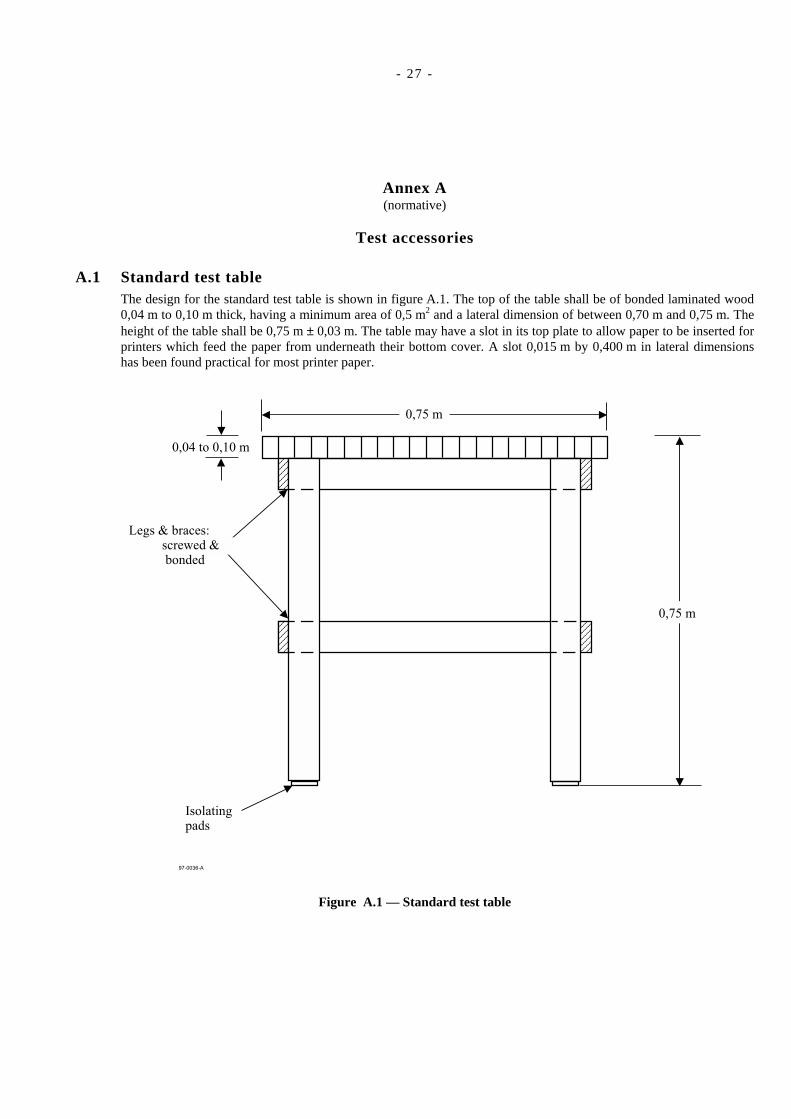
- 27 -
Annex A(normative)
Test accessories
A.1 Standard test table The design for the standard test table is shown in figure A.1. The top of the table shall be of bonded laminated wood0,04 m to 0,10 m thick, having a minimum area of 0,5 m2 and a lateral dimension of between 0,70 m and 0,75 m. Theheight of the table shall be 0,75 m ± 0,03 m. The table may have a slot in its top plate to allow paper to be inserted forprinters which feed the paper from underneath their bottom cover. A slot 0,015 m by 0,400 m in lateral dimensionshas been found practical for most printer paper.
97-0036-A
0,04 to 0,10 m
0,75 m
0,75 m
Legs & braces:screwed &bonded
Isolatingpads
Figure A.1 — Standard test table
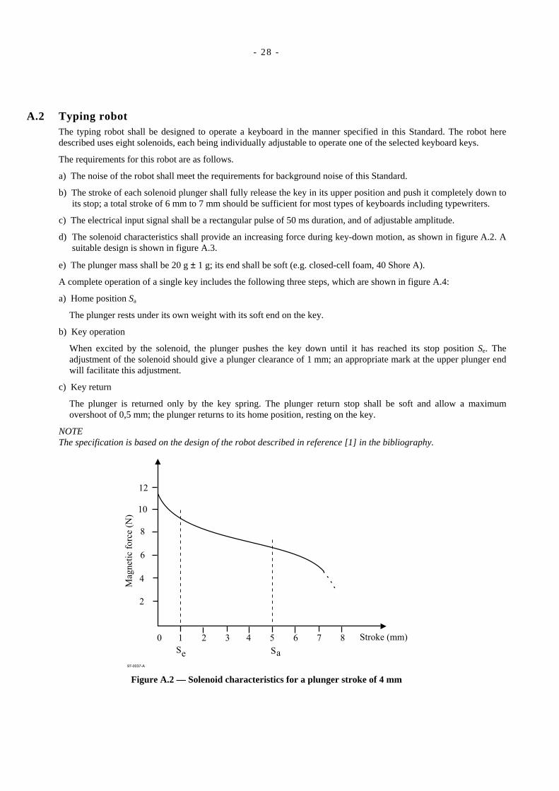
- 28 -
A.2 Typing robot The typing robot shall be designed to operate a keyboard in the manner specified in this Standard. The robot heredescribed uses eight solenoids, each being individually adjustable to operate one of the selected keyboard keys.
The requirements for this robot are as follows.
a) The noise of the robot shall meet the requirements for background noise of this Standard.
b) The stroke of each solenoid plunger shall fully release the key in its upper position and push it completely down toits stop; a total stroke of 6 mm to 7 mm should be sufficient for most types of keyboards including typewriters.
c) The electrical input signal shall be a rectangular pulse of 50 ms duration, and of adjustable amplitude.
d) The solenoid characteristics shall provide an increasing force during key-down motion, as shown in figure A.2. Asuitable design is shown in figure A.3.
e) The plunger mass shall be 20 g ± 1 g; its end shall be soft (e.g. closed-cell foam, 40 Shore A).
A complete operation of a single key includes the following three steps, which are shown in figure A.4:
a) Home position Sa
The plunger rests under its own weight with its soft end on the key.
b) Key operation
When excited by the solenoid, the plunger pushes the key down until it has reached its stop position Se. Theadjustment of the solenoid should give a plunger clearance of 1 mm; an appropriate mark at the upper plunger endwill facilitate this adjustment.
c) Key return
The plunger is returned only by the key spring. The plunger return stop shall be soft and allow a maximumovershoot of 0,5 mm; the plunger returns to its home position, resting on the key.
NOTEThe specification is based on the design of the robot described in reference [1] in the bibliography.
97-0037-A
12
10
8
6
4
2
0 1 2 3 4 5 6 7 8
Mag
net
icfo
rce
(N)
Stroke (mm)
S Se a
Figure A.2 — Solenoid characteristics for a plunger stroke of 4 mm
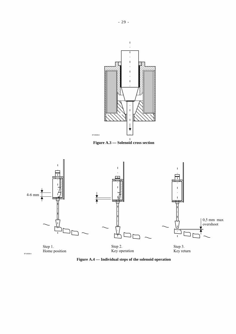
- 29 -
97-0038-A
Figure A.3 — Solenoid cross section
97-0039-A
4-6 mm
0,5 mm maxovershoot
Step 1.Home position
Step 2.Key operation
Step 3.Key return
Figure A.4 — Individual steps of the solenoid operation

- 30 -
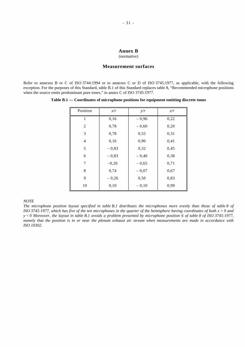
- 31 -
Annex B(normative)
Measurement surfaces
Refer to annexes B or C of ISO 3744:1994 or to annexes C or D of ISO 3745:1977, as applicable, with the followingexception. For the purposes of this Standard, table B.1 of this Standard replaces table 8, “Recommended microphone positionswhen the source emits predominant pure tones,” in annex C of ISO 3745:1977.
Table B.1 — Coordinates of microphone positions for equipment emitting discrete tones
Position x/r y/r z/r
1 0,16 – 0,96 0,22
2 0,78 – 0,60 0,20
3 0,78 0,55 0,31
4 0,16 0,90 0,41
5 – 0,83 0,32 0,45
6 – 0,83 – 0,40 0,38
7 –0,26 – 0,65 0,71
8 0,74 – 0,07 0,67
9 – 0,26 0,50 0,83
10 0,10 – 0,10 0,99
NOTEThe microphone position layout specified in table B.1 distributes the microphones more evenly than those of table 8 ofISO 3745:1977, which has five of the ten microphones in the quarter of the hemisphere having coordinates of both x > 0 andy < 0 Moreover, the layout in table B.1 avoids a problem presented by microphone position 6 of table 8 of ISO 3745:1977,namely that the position is in or near the plenum exhaust air stream when measurements are made in accordance withISO 10302.

- 32 -
- 33 -
Annex C(normative)
Installation and operating conditions for specific equipment categories
C.1 GeneralThis annex specifies installation and operating conditions for many specific categories of equipment. During testing ofsuch equipment, the conditions shall be satisfied in order to comply with this Standard. When possible, the conditionsspecified in this annex are considered to be typical of average end use. They are specified with a view to facilitate theoperation of the equipment and to enhance the reliability of the acoustical measurements.
For categories of equipment not covered in this annex, the actual test conditions used shall be described and justifiedin the test report.
The operating conditions are strictly the same for the determination of both sound power levels and emission soundpressure levels at specified positions. (See clause 3 for definitions of these quantities.)
The following categories of equipment are included.
C.2 TypewritersC.3 Character- and line-printersC.4 TeleprintersC.5 KeyboardsC.6 Copiers (duplicators)C.7 Card readers — card punchesC.8 Magnetic tape unitsC.9 Disk units and storage sub-systemsC.10 Visual display unitsC.11 Electronic unitsC.12 Microform readersC.13 Facsimile machines (Telecopiers) and page scannersC.14 Cheque processorsC.15 Personal computers and workstationsC.16 Page printersC.17 Self-service automatic teller machinesC.18 Enclosures or rack systemsC.19 CD- and DVD-ROM drives
For equipment capable of performing the functions of more than one category, for example printing and facsimiletransmission, see 5.3.
Fans, also called “air moving devices”, are often incorporated into the design of information technology andtelecommunications equipment to provide airflow for cooling. To measure such a fan as a component, for example aspart of the process of selection for design use in a computer, refer to ISO 10302.
C.2 Equipment category: TypewritersC.2.1 Description
Equipment with a keyboard for manual information entry. The information is either keyed-in and immediatelyprinted on paper character-by-character (manual typing), or keyed-in and stored for word or line editing withfollowing automatic print-out (interactive operations). Typewriters which are equipped with a full-page storage areconsidered as typewriters during manual typing and as printers (see C.3) during automatic print-out on a full page.
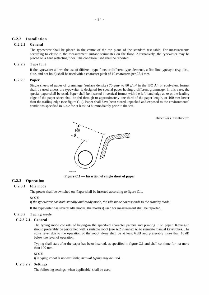
- 34 -
C.2.2 InstallationC.2.2.1 General
The typewriter shall be placed in the centre of the top plane of the standard test table. For measurementsaccording to clause 7, the measurement surface terminates on the floor. Alternatively, the typewriter may beplaced on a hard reflecting floor. The condition used shall be reported.
C.2.2.2 Type font
If the typewriter allows the use of different type fonts or different type elements, a fine line typestyle (e.g. pica,elite, and not bold) shall be used with a character pitch of 10 characters per 25,4 mm.
C.2.2.3 Paper
Single sheets of paper of grammage (surface density) 70 g/m2 to 80 g/m2 in the ISO A4 or equivalent formatshall be used unless the typewriter is designed for special paper having a different grammage; in this case, thespecial paper shall be used. Paper shall be inserted in vertical format with the left-hand edge at zero; the leadingedge of the paper sheet shall be fed through to approximately one-third of the paper length, or 100 mm lowerthan the trailing edge (see figure C.1). Paper shall have been stored unpacked and exposed to the environmentalconditions specified in 6.3.2 for at least 24 h immediately prior to the test.
Dimensions in millimetres
97-0044-A
100
Figure C.1 — Insertion of single sheet of paperC.2.3 Operation
C.2.3.1 Idle mode
The power shall be switched on. Paper shall be inserted according to figure C.1.
NOTE If the typewriter has both standby and ready mode, the idle mode corresponds to the standby mode.
If the typewriter has several idle modes, the mode(s) used for measurement shall be reported.
C.2.3.2 Typing mode
C.2.3.2.1 General
The typing mode consists of keying-in the specified character pattern and printing it on paper. Keying-inshould preferably be performed with a suitable robot (see A.2 in annex A) to simulate manual keystrokes. Thenoise level due to the operation of the robot alone shall be at least 6 dB and preferably more than 10 dBbelow the level of operation.
Typing shall start after the paper has been inserted, as specified in figure C.1 and shall continue for not morethan 100 mm.
NOTE If a typing robot is not available, manual typing may be used.
C.2.3.2.2 Settings
The following settings, when applicable, shall be used.
- 35 -
a) Impression control: as recommended for a single sheet of paper.
b) Multi-copy control: set for a single sheet.
c) Line spacing: double-line spacing.
d) Margin: 25 mm from the edges; the end-of-line indicator (bell) shall be disconnected.
e) Paperbail rollers: the paperbail rollers shall be set 25 mm in from the edges of the paper; the others shallbe equally spaced between.
C.2.3.2.3 Character pattern
The test pattern characters shall be
etnaiv etnaiv etnaiv etnaiv...
and so on until a full printline of approximately 60 characters has been completed.
The single space between each group of six characters is required as part of the pattern. The carriage returnafter each line is part of the operation.
NOTE 1A maximum of two characters may be replaced by other small letters, if there is a need for adjustment of therobot.
NOTE 2Should small letters not be available, capital letters may be used instead; equivalent conditions may beselected for typewriters with non-Latin character sets.
C.2.3.2.4 Operating speed
For manual operations the typing speed shall be five characters per second.
The specified characters shall be keyed in at a rate of five characters per second until the buffer is filled up; amaximum buffer capacity of one printline shall not be exceeded. The stored information shall then beimmediately printed (maximum one line) at the maximum printing speed.
C.2.4 Measurement durationThe time-averaged sound pressure level shall be measured for at least the duration specified in 6.7.2 or 7.7.2 duringthe following operations.
a) For manual operations: measure during continuous typing over at least three full lines.
b) For interactive operations: measure during keying-in and printing-out until at least three full lines have beenprinted.
C.3 Equipment category: Character and line printersC.3.1 Description
This category covers electronically controlled equipment which prints stored information on paper and is notnormally keyboard-operated, and the noise output of which depends on the print pattern. The output may beobtained by means of impact printing (e.g. typebar-, train-, chain- or band-printers, printwheel, type-element ormatrix printers) or by non-impact printing (e.g. ink jet, electro-erosion, or thermal printers).
NOTEFor teleprinters, see C.4; for page printers which have noise output independent of the print pattern, see C.16.
C.3.2 InstallationC.3.2.1 General
Floor-standing printers shall be installed on the hard reflecting floor. Printers which are normally placed on aspecial stand shall be installed on such a stand on the reflecting floor. Printers which are placed on an officetable or desk and which take paper from, or stack paper on, the floor, shall, if possible, be placed in the centre of
- 36 -
the top plane of the standard test table, using the floor to support the paper. For such measurements according toclause 7, the measurement surface terminates on the reflecting floor.
Table-top printers, which do not use the floor for the paper supply or exit stack, shall be placed on the hardreflecting floor for measurements according to clause 6 or 7 and on the test table for measurements according toclause 8.
For the purposes of declaring A-weighted emission sound pressure level according to ECMA-109, the bystanderpositions are applicable unless the printer also has a data entry keyboard. In this latter case, the operator positionis applicable.
C.3.2.2 Type style
If the printer allows the use of different type styles or different type elements, a type style typical of normal use(resident standard type style), with a character pitch of 10 characters per 25,4 mm and with a number of 6 linesper 25,4 mm shall be used. If this is not possible an adjustment as close as possible to these values shall bechosen. Condensed or extended characters, shall not be used.
C.3.2.3 Paper
Either single sheets of paper of grammage 70 g/m2 to 80 g/m2 or continuous, folded or rolled stationery ofgrammage 50 g/m2 to 60 g/m2 shall be used, unless the printer is designed for special paper having a differentmass. In this latter case, the special paper shall be used. The quantity of paper available for printing shall be asclose as possible to the maximum capacity of the printer. The form width shall be the widest that is commonlyavailable for the printer and shall be described in the test report. For special applications (e.g. when the materialto be printed is a passbook or cheque) the material shall be typical for customer usage and shall be described inthe test report.
Paper storage and unpacking shall be carried out in accordance with the machine manufacturer's instructions. Ifthere are no such instructions, paper shall have been stored unpacked and exposed to the environmentalconditions specified in 6.3.2 for at least 24 h immediately prior to the test.
C.3.3 OperationC.3.3.1 Paper position
Except when single sheets are being used, the paper shall be loaded and fed through for a length of at least tentimes its width. If single sheets are being used, the paper should be inserted in such a way that it can be printedon for at least 60 % of the page length with the printing area centred vertically.
C.3.3.2 Idle mode
The power shall be switched on.
NOTEIf the printer has both standby and ready modes, the idle mode corresponds to the standby mode.
If the printer has several idle modes, the mode(s) used for measurement shall be reported.
C.3.3.3 Operating mode (Print mode)
C.3.3.3.1 General
Printers with single-sheet feeding devices shall be tested in best quality mode. Paper of size A4 or of anequivalent format (portrait) is automatically fed.
Printers with continuous stationery shall be tested in draft mode with maximum paper width.
Printers capable of printing both single sheets of paper and continuous stationery shall be tested in bothconfigurations.
The print mode consists of printing a character pattern specified in C.3.3.3.3.
For graphic printers whose print speed is specified per ISO 11160-1:1996 [7] while printing graphic mode perISO/IEC 10561:1999 [2], a second operating mode shall be tested and reported: the second mode consists ofprinting the test pattern in ISO/IEC 10561:1999, annex D.
C.3.3.3.2 Settings
The following settings, when applicable, shall be used.
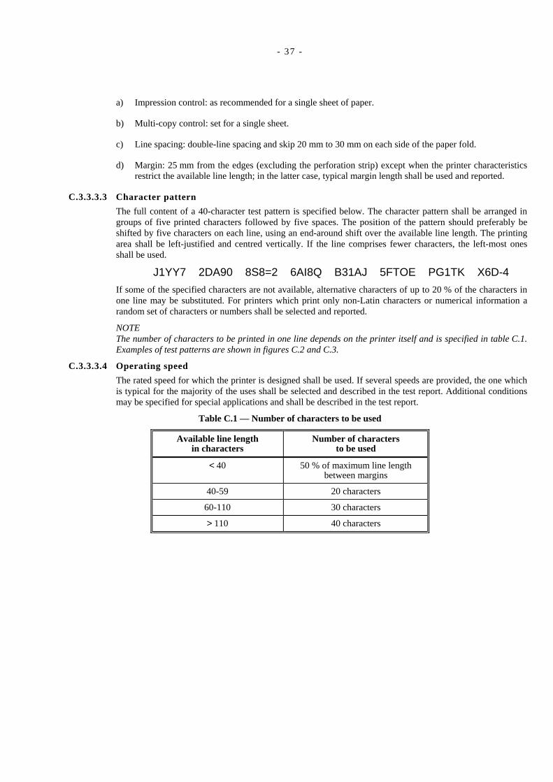
- 37 -
a) Impression control: as recommended for a single sheet of paper.
b) Multi-copy control: set for a single sheet.
c) Line spacing: double-line spacing and skip 20 mm to 30 mm on each side of the paper fold.
d) Margin: 25 mm from the edges (excluding the perforation strip) except when the printer characteristicsrestrict the available line length; in the latter case, typical margin length shall be used and reported.
C.3.3.3.3 Character pattern
The full content of a 40-character test pattern is specified below. The character pattern shall be arranged ingroups of five printed characters followed by five spaces. The position of the pattern should preferably beshifted by five characters on each line, using an end-around shift over the available line length. The printingarea shall be left-justified and centred vertically. If the line comprises fewer characters, the left-most onesshall be used.
J1YY7 2DA90 8S8=2 6AI8Q B31AJ 5FTOE PG1TK X6D-4
If some of the specified characters are not available, alternative characters of up to 20 % of the characters inone line may be substituted. For printers which print only non-Latin characters or numerical information arandom set of characters or numbers shall be selected and reported.
NOTEThe number of characters to be printed in one line depends on the printer itself and is specified in table C.1.Examples of test patterns are shown in figures C.2 and C.3.
C.3.3.3.4 Operating speed
The rated speed for which the printer is designed shall be used. If several speeds are provided, the one whichis typical for the majority of the uses shall be selected and described in the test report. Additional conditionsmay be specified for special applications and shall be described in the test report.
Table C.1 — Number of characters to be used
Available line lengthin characters
Number of charactersto be used
< 40 50 % of maximum line lengthbetween margins
40-59 20 characters
60-110 30 characters
> 110 40 characters
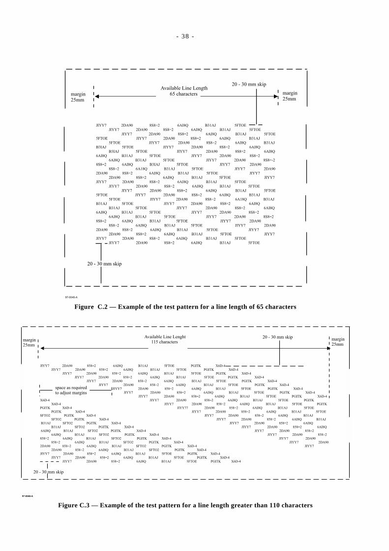
- 38 -
Available Line Length65 characters
JIYY7 2DA90 8S8=2 6AI8Q B31AJ 5FTOEJIYY7 2DA90 8S8=2 6AI8Q B31AJ 5FTOE
JIYY7 2DA90 8S8=2 6AI8Q B31AJ 5FTOE5FTOE JIYY7 2DA90 8S8=2 6AI8Q B31AJ
5FTOE JIYY7 2DA90 8S8=2 6AI8Q B31AJB3IAJ 5FTOE JIYY7 2DA90 8S8=2 6AI8Q
B3IAJ 5FTOE JIYY7 2DA90 8S8=2 6AI8Q6AI8Q B31AJ 5FTOE JIYY7 2DA90 8S8=2
6AI8Q B31AJ 5FTOE JIYY7 2DA90 8S8=-28S8=2 6AI8Q B3IAJ 5FTOE JIYY7 2DA90
8S8=2 6A18Q B31AJ 5FTOE JIYY7 2DA902DA90 8S8=2 6AI8Q B31AJ 5FTOE JIYY7
2DA90 8S8=2 6AI8Q B31AJ 5FTOE JIYY7JIYY7 2DA90 8S8=2 6AI8Q B31AJ 5FTOE
JIYY7 2DA90 8S8=2 6AI8Q B31AJ 5FTOEJIYY7 2DA90 8S8=2 6AI8Q B31AJ 5FTOE
5FTOE JIYY7 2DA90 8S8=2 6AI8Q B31AJ5FTOE JIYY7 2DA90 8S8=2 6A18Q B31AJ
B31AJ 5FTOE JIYY7 2DA90 8S8=2 6AI8QB31AJ 5FTOE JIYY7 2DA90 8S8=2 6AI8Q
6AI8Q B31AJ 5FTOE JIYY7 2DA90 8S8=26AI8Q B31AJ 5FTOE JIYY7 2DA90 8S8=2
8S8=2 6AI8Q B31AJ 5FTOE JIYY7 2DA908S8=2 6AI8Q B31AJ 5FTOE JIYY7 2DA90
2DA90 8S8=2 6AI8Q B31AJ 5FTOE JIYY72DA90 8S8=2 6AI8Q B31AJ 5FTOE JIYY7
JIYY7 2DA90 8S8=2 6AI8Q B31AJ 5FTOEJIYY7 2DA90 8S8=2 6AI8Q B31AJ 5FTOE
margin25mm
margin25mm
20 - 30 mm skip
20 - 30 mm skip
97-0045-A
Figure C.2 — Example of the test pattern for a line length of 65 characters
97-0046-A
Available Line Lenght115 characters
JIYY7 2DA90 858=2 6AI8Q B31AJ 5FTOE PGITK X6D-4JIYY7 2DA90 858=2 6AI8Q B31AJ 5FTOE PGITK X6D-4
JIYY7 2DA90 858=2 6AI8Q B31AJ 5FTOE PGITK X6D-4JIYY7 2DA90 858=2 6AI8Q B31AJ 5FTOE PGITK X6D-4
JIYY7 2DA90 858=2 6AI8Q B31AJ 5FTOE PGITK X6D-4JIYY7 2DA90 858=2 6AI8Q B31AJ 5FTOE PGITK X6D-4
JIYY7 2DA90 858=2 6AI8Q B31AJ 5FTOE PGITK X6D-4JIYY7 2DA90 858=2 6AI8Q B31AJ 5FTOE PGITK X6D-4
JIYY7 2DA90 858=2 6AI8Q B31AJ 5FTOE PGITK X6D-4X6D-4 JIYY7 2DA90 858=2 6AI8Q B31AJ 5FTOE PGITK
X6D-4 JIYY7 2DA90 858=2 6AI8Q B31AJ 5FTOE PGITKPGITK X6D-4 JIYY77 2DA90 858=2 6AI8Q B31AJ 5FTOE
PGITK X6D-4 JIYY7 2DA90 858=2 6AI8Q B31AJ 5FTOESFTO2 PGITK X6D-4 JIYY7 2DA90 858=2 6AI8Q B31AJ
SFTO2 PGITK X6D-4 JIYY7 2DA90 858=2 6AI8Q B31AJB31AJ SFTO2 PGITK X6D-4 JIYY7 2DA90 858=2 6AI8Q
B31AJ SFTO2 PGITK X6D-4 JIYY7 2DA90 858=2 6AI8Q6AI8Q B31AJ SFTO2 PGITK X6D-4 JIYY7 2DA90 858=2
6AI8Q B31AJ SFTO2 PGITK X6D-4 JIYY7 2DA90 858=2858=2 6AI8Q B31AJ SFTO2 PGITK X6D-4 JIYY7 2DA90
858=2 6AI8Q B31AJ SFTO2 PGITK X6D-4 JIYY7 2DA902DA90 858=2 6AI8Q B31AJ SFTO2 PGITK X6D-4 JIYY7
2DA90 858=2 6AI8Q B31AJ SFTO2 PGITK X6D-4JIYY7 2DA90 858=2 6AI8Q B31AJ 5FTOE PGITK X6D-4
JIYY7 2DA90 858=2 6AI8Q B31AJ 5FTOE PGITK X6D-4JIYY7 2DA90 858=2 6AI8Q B31AJ 5FTOE PGITK X6D-4
margin25mm
margin25mm
20 - 30 mm skip
20 - 30 mm skip
space as requiredto adjust margins
Figure C.3 — Example of the test pattern for a line length greater than 110 characters
- 39 -
C.3.4 Measurement durationThe time-averaged sound pressure level shall be measured for at least the duration specified in 6.7.2 or 7.7.2 duringthe following operations:
a) Single-page form: measure during continuous printing over at least 60 % of the page length; if the printer hasan automatic paper feed mechanism, at least three pages shall be printed.
b) Folded stationery: measure during continuous printing over at least three pages.
c) Rolled stationery: measure during continuous printing over a length equal to at least the paper width.
d) Passbook: measure during printing of a single line on the middle pages during a complete operation cyclefrom insertion to ejection (for details see C.17).
C.4 Equipment category: TeleprintersC.4.1 Description
This category covers equipment operating as a send/receive machine basically comprising a keyboard, a printingunit, a mechanical or electronic send/receive unit (line control unit) and (integrated or optional) a memory unit(electronic, paper tape punch or reader, magnetic tape, disk or cassette).
Two typical uses are:
a) Keyboard operation (when in local or transmission mode): the information is keyed-in by manual typing andimmediately printed on paper and/or stored in the memory.
b) Automatic operation (when in local or on-line mode): the machine prints automatically the informationreceived from line network or from the memory unit.
When a teleprinter is fitted with an auxiliary unit which produces noise (e.g. paper tape punch/reader, magnetictape, disk or cassette), the machine shall be tested with and without the unit in operation.
In some cases a teleprinter can be available in receive-only configuration (without keyboard). That machine isconsidered to be a character or line printer (according to C.3).
C.4.2 InstallationC.4.2.1 General
For keyboard operation of the teleprinter, the general installation conditions for typewriters shall apply (seeC.2).
For automatic operation of the teleprinter, the general installation conditions for printers shall apply (see C.3).
C.4.2.2 Paper
Either single sheets of paper of grammage 70 g/m2 to 80 g/m2 or continuous, folded or rolled stationery ofgrammage 50 g/m2 to 60 g/m2 shall be used, unless the printer is designed for special paper having a differentgrammage. In this latter case, the special paper shall be used. The quantity of paper available for printing shallbe as close as possible to the maximum capacity of the printer. The form width shall be the widest that iscommonly available for the printer and shall be described in the test report. For special applications (e.g. whenthe material to be printed is a passbook or cheque) the material shall be typical for customer usage and shall bedescribed in the test report.
If in typical use, multi-part stationery is employed, an additional test with such stationery shall be carried outand described in the test report.
Paper storage and unpacking shall be carried out in accordance with the machine manufacturer's instructions. Ifthere are no such instructions, paper shall have been stored unpacked and exposed to the environmentalconditions specified in 6.3.2 for at least 24 h immediately prior to the test.
- 40 -
C.4.3 OperationC.4.3.1 Idle mode
The power shall be switched on and paper shall be inserted.
NOTEIf the teleprinter has both standby and ready modes, the idle mode corresponds to the standby mode.
C.4.3.2 Operating mode (Print mode)
For keyboard operation of the teleprinter, the operating conditions specified for keyboards shall apply (see C.5).
For automatic operation of the teleprinter, the operating conditions specified for printers shall apply (see C.3).
C.4.4 Measurement durationThe time-averaged sound pressure level shall be measured for at least the duration specified in 6.7.2 or 7.7.2.
For keyboard operation of the teleprinter, the requirements specified for typewriters shall apply (see C.2.4).
For automatic operation of the teleprinter, the requirements specified for printers shall apply (see C.3.4).
C.5 Equipment category: KeyboardsC.5.1 Description
This category covers equipment for manual data entry fixed or connected (via a cable or other data transmissionmeans) to other units, e.g. visual display units, computer console, hand-held calculator, etc.
C.5.2 InstallationKeyboards shall be installed in accordance with the relevant clauses of this Standard, except for measurementsaccording to clause 6 or 7. The keyboard may be placed in the centre of the top plane of the standard test table ifrequired for operation, provided this is reported.
C.5.3 OperationC.5.3.1 Operating mode (keying-in)
Keying-in shall be performed at a rate of five characters per second.
A suitable robot (see A.2) should be used to simulate manual keystrokes. The noise level due to the operation ofthe robot alone shall be at least 6 dB and preferably more than 10 dB below the level of operation.
If the keyboard has acoustical feedback, the minimum volume setting shall be used for the test.
NOTEIf a typing robot is not available, manual keying-in may be used.
C.5.3.2 Test pattern
a) For alphanumeric keyboards, the test pattern shall be as specified for typewriters (see C.2.3.2.3).
b) For numeric keyboards, the test pattern shall be four digits plus function key, the keys selected shall bereported.
C.5.4 Measurement durationThe time-averaged sound pressure level shall be measured for at least the duration specified in 6.7.2 or 7.7.2; therequirements specified for typewriters shall apply (C.2.4).
C.5.5 Measurement uncertaintyThe measurement uncertainty for determining noise emission levels for keyboard operation has not yet beenverified and may be greater than those given in 6.2, 7.2 and 8.2.
C.6 Equipment category: Copiers (duplicators)C.6.1 Description
This category covers equipment which can produce one or more copies from a master. Such equipment can be cou-
- 41 -
pled with one or more additional attachments and features. These may be in the form of input, output or internaldevices for a variety of copying needs. Input devices can be in the form of master document loading, handling andregistering, or special paper feeders for continuous stationery or label printing. Output devices can be in the formof copy handlers such as sorters, automatic staplers, stackers and binders. The equipment may have an internalreversing device(s) for handling two-sided originals and producing two-sided copies; i.e. automatic duplexing. Thecopier may also offer full colour copying from full colour masters, or highlight colour copying.
C.6.2 InstallationC.6.2.1 General
Due to the nature of product operation, noise emitted by the copier in operating mode(s) may fluctuatesignificantly with time. Therefore, for this category of equipment, sound power level determination according toclause 6 (reverberation chamber) may have restrictions to achieve reliable test results: only sound power level ofrepeated, or cyclic operations will be determined with the uncertainty stated, and measurement duration longerthan that in free field over a reflecting plane may be required.
Floor-standing copiers shall be installed on the hard reflecting floor. Copiers which are normally placed on aspecial stand or special table shall be installed on such a stand or table on the reflecting floor. Copiers which areplaced on a normal office table or desk and which take paper from, or stack paper on, the floor, shall, if possible,be placed in the centre of the standard test table, using the floor to support the paper. For such measurementsaccording to clause 7, the measurement surface terminates on the reflecting floor.
Table-top copiers, which do not use the floor for the paper supply or exit stack, shall be placed on the hardreflecting floor for measurements according to clause 6 or 7 and on the standard test table for measurementsaccording to clause 8.
The same installation conditions shall be followed when the copier has attachments.
C.6.2.2 Paper
Either single sheets of paper of grammage 70 g/m2 to 80 g/m2 or continuous, folded or rolled stationery ofgrammage 50 g/m2 to 60 g/m2 shall be used, unless the copier is designed for special paper having a differentgrammage; in this case, the special paper shall be used. The quantity of paper available for copying shall be asclose as possible to the maximum capacity of the copier. The form width shall be the widest that is commonlyavailable for the copier and shall be described in the test report. For special applications (e.g. when the materialto be printed is a passbook or cheque) the material shall be typical for customer usage and shall be described inthe test report.
Paper storage and unpacking shall be carried out in accordance with the machine manufacturer's instructions. Ifthere are no such instructions, paper shall have been stored unpacked and exposed to the environmentalconditions specified in 6.3.2 for at least 24 h immediately prior to the test.
C.6.3 OperationC.6.3.1 Idle mode
Power shall be switched on and the copier shall be loaded with a suitable paper supply.
C.6.3.2 Operating mode
C.6.3.2.1 General
The nominal speed for which the copier has been designed shall be used; if several speeds are provided, theone which is typical for the majority of the uses shall be employed. The copier shall be adjusted to normalexposure, and tests shall be carried out without using any reduction/enlargement facility, if provided.
Additional machine set-up conditions may be considered, as follows.
a) Copying without additional attachments
An operation cycle shall consist of continuously copying a single master.
b) Copying with additional attachments: input and output devices
When a copying system combines several features/attachments, a "full system" operation cycle shallcomprise the use of the maximum number of features/attachments allowable at least once. This mayinclude using all the features/attachments on the copier or just some of them. Where all thefeatures/attachments cannot be used together in one operation cycle, several different operating
- 42 -
combinations should be considered. The combination which is typical of use shall be selected anddescribed in the test report.
C.6.3.2.2 Input devices
a) Automatic loading of originals
An operation cycle shall consist of placing five masters in the device input tray and making five copiesof each master. Copies are ejected into a single stationery output tray.
b) Copying from continuous stationery
An operation cycle shall consist of feeding five pages of continuous stationery through the registeringdevice and making five copies of each master. Copies are ejected into a single stationery output tray.
C.6.3.2.3 Output devices
a) Sorting
The operation shall start with an empty sorter. An operation cycle shall comprise the registering of onemaster and making five copies ejected into five consecutive sorter bins. (Any copies made duringadditional operation cycles shall be sorted into the same five consecutive bins.)
b) Stacking
If the copier is equipped with an integral mechanism to separate copy sets generated sequentially, it willgenerally be fitted with an input master loading device. The operation cycle shall comprise the placingof five originals into the device input tray and one copy of each shall be ejected into the stacker.
c) Automatic stapling
Automatic stapling may be provided in the form of a separate output device, or being fitted as integral toa sorter or stacker. Copiers equipped with this device will generally be fitted with an input masterloading device. The operation cycle shall comprise the stapling of a set of copies from five masters for atotal of five stapled sets, and ejected into the output tray.
d) Copying on continuous stationery
An operation cycle shall comprise copying one master on five pages for folded stationery or a 2-mlength for rolled stationery.
e) Auxiliary equipment
If a copier is supplied with an accessory or integral equipment (e.g. a binder), the tests shall be carried outwith and without the use of this equipment in the operation cycle.
f) Two-sided copying
Copiers equipped with this feature can either
1) handle two-sided masters and produce from them one-sided or two-sided copies, or2) handle one-sided masters only, and produce from them one-sided or two-sided copies.
Copiers equipped with this device will generally be fitted with an input master loading device.
An operation cycle for type 1) above shall comprise the making of two one-sided copies (one of each ofthe sides of the master) or one two-sided copy from one two-sided master. This operation cycle is to berepeated five times. An operation cycle for type b) above shall comprise the making of one two-sidedcopy from two one-sided masters, this operation cycle is to be repeated five times.
g) Colour copying
The operation cycle for copiers fitted with this feature shall be the copying from one one-sided fullcolour master; one copy is made and automatically ejected into a single stationery output tray.
h) Highlight-colour copying
The operation cycle for copiers fitted with this feature shall be as for monochrome. (Copies shouldcontain highlight-colour from a full text master, e.g. four lines in highlight-colour using the test patternas specified in C.3).
- 43 -
C.6.4 Measurement durationThe time-averaged sound pressure level shall be measured for at least five operation cycles and for at least theduration specified in 6.7.2 or 7.7.2.
C.7 Equipment category: Card readers and card punchesC.7.1 Description
Equipment of this category may perform a single function, such as reading the information from, or punching itinto, a punched card. The two functions may also be combined in one machine which allows the use of bothfunctions in one process or to use them separately. The number of cards processed per unit time depends forreaders mainly on the nominal processing speed; for punches it may be significantly influenced by the total numberof columns to be punched per card.
For equipment which performs similar functions such as card duplicating machines, card verifiers, card ordocument sorters and collators, code interpreters (with printing features), paper tape readers and punches, thefollowing installation and operating conditions may also be applied.
C.7.2 InstallationThe equipment shall be installed in accordance with the relevant clauses of this Standard.
C.7.3 OperationC.7.3.1 Idle mode
The power shall be switched on and the equipment shall be ready for reading or punching cards.
C.7.3.2 Operating mode (Reading or punching mode)
If equipment of this category is capable of both reading and punching in one process, the operating mode shallconsist of both punching and reading cards as specified below. If equipment allows only the use of thesefunctions separately, the operating mode shall be punching.
The specified character pattern shall be read from, or punched into and/or read from, each card; approximately40 % of the maximum number of columns (usually 80) shall contain information. The specified character patternshall be arranged in groups of five characters followed by five spaces:
J1YY7 2DA90 8S8=2 6AI8Q B31AJ 5FTOE PG1TK X6D-4
C.7.4 Measurement durationThe time-averaged sound pressure level shall be measured for at least the duration specified in 6.7.2 or 7.7.2 duringprocessing of a random card deck of at least 10 cards.
C.8 Equipment category: Magnetic tape unitsC.8.1 Description
This category covers equipment for writing on, and reading from, a magnetic tape wound on reels or within acassette or a cartridge. A unit may contain one or more separately operable tape drives.
C.8.2 InstallationInstallation shall be in accordance with the relevant clauses of this Standard.
C.8.3 OperationC.8.3.1 Idle mode
C.8.3.1.1 Idle unloaded mode
The power shall be switched on and the tape shall not be in the tape path.
C.8.3.1.2 Idle loaded mode
The power shall be switched on and the tape shall be loaded and the equipment shall be ready to receive andrespond to control line commands to any drive. In multiple drive units, all drives shall be loaded and ready.
- 44 -
C.8.3.2 Operating modes
One of the modes specified below shall be used as applicable.
In multiple drive units, only one drive shall be in operating mode; all other drives shall be in the idle loadedmode.
C.8.3.2.1 Read/Write mode
Start, read or write, stop — with command timing for capstan (or equivalent) operation as follows.
Capstan on-time, in milliseconds, is set at the time needed to pass 130 mm of tape at the rated tape speed, s,defined as
mssm
mm130
s
rounded to the nearest millisecond.
The off-time is equal to 0,7 to 1 times the on-time.
NOTEFor a magnetic tape of 12,7 mm width, 130 mm of tape corresponds to a block length of 4 096 bytes at32 bpmm. Higher densities should use correspondingly larger block sizes, such that the total on-time for alldensity machines will be approximately equal. At 63 bpmm, use a block length of 8 192 bytes; at 246 bpmm,use a block of 32 768 bytes.
C.8.3.2.2 Streaming mode
Logical forward run while writing.
C.8.4 Measurement durationThe time-averaged sound pressure level shall be measured, for at least the duration specified in 6.7.2 or 7.7.2, for atleast twenty consecutive start/stop operations in accordance with C.8.3.2.1 or streaming operations in accordancewith C.8.3.2.2.
C.9 Equipment category: Disk units and storage subsystemsC.9.1 Description
This category covers equipment for writing on, and reading from, one or more rotating magnetic or optical disks.Disks may be removable or non-removable. Magnetic disks may be flexible or rigid. A unit may contain one ormore separately operable disk drives.
NOTEFor read-only optical disk drives (e.g. CD- and DVD-ROM drives), see C.19.
C.9.2 InstallationInstallation shall be in accordance with 5.1 and 8.5. Disk units which form part of a personal computer or rack-mounted equipment shall be tested according to C.15 or C.18 as appropriate. Disk units which are tested as sub-assemblies shall be installed as sub-assemblies per 5.1.7.
C.9.3 OperationC.9.3.1 Idle mode
C.9.3.1.1 Idle ready
Disk(s) shall be loaded, power on, unit ready to receive and respond to control link commands with spindleup to speed and read/write heads in track-following mode.
For systems having a single drive, the drive shall be as described above. For systems with multiple drives orfor storage subsystems, the number of drives that are simultaneously operable by the host CPU shall beoperated as specified above. All other drives shall be in the idle mode typical of normal use for the system.
C.9.3.1.2 Idle standby
If power-saving modes are available, such modes may be tested and if tested shall be described in the report.
- 45 -
C.9.3.2 Operating mode
For units having a single drive, the drive shall be operating as described below.
For units with multiple drives, or for storage subsystems, the number of drives that are simultaneously operableby the host CPU shall be operated as specified below. All other drives shall be in the idle mode, typical ofnormal use for the system.
Randomly select a cylinder/track to be sought in such a way that every cylinder/track has equal probability ofbeing selected. (If the drive incorporates an algorithm to perform seeks in a more efficient non-random order,then this algorithm may be used. In this case the drive should be given a command or commands to read or writea random selection of files, and the drive algorithm will decide the order in which the commands are executed.The file length shall be adjusted to achieve the seek rate defined below). Seek to that track, then delay for a timeperiod tD achieving the required seek rate ns within ± 10 % according to the following formula:
ns = 0,4 / (tT + tL)
tD = 1,5 tT + 2,5 tL
where
ns is the average seek rate, expressed in seeks per second;
tT is the manufacturer's published time to seek from one random track to another without includingrotational latency;
tL is the time, in seconds, for the drive to rotate by half a revolution.
Repeat the seek process. No other intentional delay while selecting the cylinder is allowed. The average numberof seeks per second along with the seek algorithm shall be reported with the acoustical data.
If the drive is operating in a system and if the system is not capable of achieving the required seek rate, the driveshall be operated at the maximum seek rate achievable.
If the drive is operating in a multiple drive system in a Redundant Array of Inexpensive Disks (RAID)environment, the drive shall be operated at the maximum seek rate achievable compatible with the system RAIDlevel in use.
C.9.4 Measurement durationThe time-averaged sound pressure level shall be measured for at least the duration specified in 6.7.2 or 7.7.2.
NOTEAcoustical “beating” in multi-drive arrays can occur over periods of time that are long relative to therequirements of 6.7.2 and 7.7.2. The resulting variation in sound pressure level at microphone positions can have asignificant effect on the variability of A-weighted sound power level determined for the equipment. This variabilitycan be reduced by increasing the measurement time to include several beating cycles.
C.10 Equipment category: Visual display units and terminalsC.10.1 Description
This category covers equipment which displays information on a screen, and which may be equipped with akeyboard for information entry. The keyboard may be fixed to the display unit or connected to it by means of acable or other means of data transmission.
The units in this category may emit significant noise in the 16 kHz octave band. If the noise from the 16 kHzoctave band is broad-band in character, the A-weighted levels shall be calculated from one-third-octave bandmeasurements which include the 16 kHz octave band. If the noise in the 16 kHz octave band contains discretetone(s), then the 16 kHz octave band shall not be included in the determination of the A-weighted levels.
For equipment which emits sound in the 16 kHz octave band, the procedures specified in ECMA-108 for reportingsound power levels shall be used (see table 4).
C.10.2 InstallationInstallation shall be in accordance with the relevant clauses of this Standard.
- 46 -
C.10.3 OperationC.10.3.1 Idle mode
The power shall be switched on and the equipment shall be in a steady-state condition, with air-movingdevice(s), if any, running and the representative pattern shall be displayed on the screen. The keyboard shall notbe operated.
Preliminary tests should be run to determine if the emissions are significantly sensitive to the pattern displayedon the screen. If so, a pattern representative of maximum emission values for a typical user shall be determined.If not, the representative pattern shall be defined to be a full character set displayed on the screen and repeateduntil all positions on the screen are used. The representative pattern used shall be documented and reported.
C.10.3.2 Operating mode (Typing mode), if applicable
The typing mode consists of keying-in the information specified for keyboards (see C.5).
C.10.3.3 Power saving mode
If power saving modes are available, such modes may be tested in addition to the modes defined in C.10.3.1,described and reported.
C.10.4 Measurement durationThe time-averaged sound pressure level shall be measured for at least the duration specified in 6.7.2 or 7.7.2.
C.11 Equipment category: Electronic unitsC.11.1 Description
This category covers equipment such as processors, electronic memories and controllers, containing only electroniccircuits, power supplies but no moving mechanical parts except those associated with cooling.
C.11.2 InstallationInstallation shall be in accordance with the relevant clauses of this Standard.
C.11.3 OperationC.11.3.1 Operating mode
Operate in the steady-state condition with normal load on all cooling devices, power supplies, and distributedpower supply elements. No data operations are required. For electronic units, the idle and operating modes aredeemed to be the same.
C.11.3.2 Power saving mode
If power saving modes are available, such modes may be tested in addition to the modes defined in C.11.3.1,described and reported.
C.11.4 Measurement durationThe time-averaged sound pressure level shall be measured for at least the duration specified in 6.7.2 or 7.7.2.
C.12 Equipment category: Microform readersC.12.1 Description
This category covers equipment to display micro-images. Microform readers may differ from each other,depending on the different types of microforms to be used, such as microfiche, aperture cards and rollfilm.
C.12.2 InstallationInstallation shall be in accordance with the relevant clauses of this Standard.
C.12.3 OperationC.12.3.1 Idle mode
The power shall be switched on and the equipment shall be ready to display.
- 47 -
C.12.3.2 Operating mode
The microform shall be inserted and the micro-image adjusted and displayed.
The following two operations may be performed with partial or full automation.
a) Equipment for microfiche and aperture cards: the micro-image shall be adjusted in two diagonal corners bymoving its support; an image shall be kept stationary.
b) Equipment for rollfilm with a full reel of microfilm loaded into the device: the image approximately in themiddle of the film shall be sought and adjusted; the rollfilm shall be transported automatically.
The operation used during the test shall be described in the test report.
C.12.4 Measurement durationThe time-averaged sound pressure level shall be measured for a minimum of three operation cycles and for at leastthe duration specified in 6.7.2 or 7.7.2.
C.13 Equipment category: Facsimile machines (telecopiers) and page scannersC.13.1 Description
C.13.1.1 Facsimile machines
This category covers equipment operating as a send/receive machine, basically comprising a numeric keyboard,a paper feeding device, a scanner, a print unit and an electronic send/receive control unit. Telecopiers are usedfor transmitting text, drawings and graphic information via public transmission networks.
C.13.1.2 Page scanners
This category covers equipment operating as a scanner which detects text, drawing and graphical informationfrom full sheets of paper and comprises a paper feeding device and a scanning mechanism.
C.13.2 InstallationC.13.2.1 General
The facsimile machine shall be installed in accordance with the relevant clauses of this Standard. For thepurposes of reporting A-weighted emission sound pressure levels in accordance with ECMA-109, the bystanderpositions are applicable.
C.13.2.2 Paper
The paper that is used shall be in accordance with the machine manufacturer's instructions. If there are noinstructions, either single sheets of paper of grammage 70 g/m2 to 80 g/m2, or continuous, folded or rolledstationery of grammage 50 g/m2 to 60 g/m2 shall be used. The width of the rolled stationery shall be typical forthe device; if different widths can be used, the most common one shall be used and shall be described in the testreport.
Paper storage and unpacking shall be carried out in accordance with the machine manufacturer's instructions. Ifthere are no such instructions, paper shall have been stored unpacked and exposed to the environmental con-ditions specified in 6.3.2 for at least 24 h immediately prior to the test.
C.13.3 OperationC.13.3.1 Idle mode
Power shall be switched on and the equipment shall be ready for sending or receiving.
C.13.3.2 Operating mode (Sending or receiving mode)
Information shall be transmitted at a rate and resolution for which the facsimile machine or scanner is designedto be used. If more than one speed and resolution are provided, the one which is typical of the majority of usesshall be employed and reported. If the printing of transmission receipts is the default setting for the equipment,then such printing shall be included in the measurement. Additional conditions may be specified and describedin the test report. Both the sending and the receiving modes shall be measured for the facsimile machine. Thehighest value so determined shall be reported.
- 48 -
C.13.4 Measurement durationThe time-averaged sound pressure level shall be measured for at least one full transmission cycle, in either thesending or the receiving mode, and for at least the duration specified in 6.7.2 or 7.7.2.
C.14 Equipment category: Cheque processorsC.14.1 Description
Equipment of this category may perform a single function such as printing (or encoding) information onto cheques,reading information from cheques, printing lists, storing/retrieving information from a flexible disk cartridge, orsorting cheques.
C.14.2 InstallationC.14.2.1 General
The equipment shall be installed in accordance with the relevant clauses of this Standard.
C.14.2.2 Paper
C.14.2.2.1 Cheque stock
Typically, a large variety of cheque sizes and grammage of paper are used. To allow a standard method, thefollowing specification defines the properties of the cheques to be used.
a) Length: 140 mm to 160 mm.
b) Height: 70 mm to 90 mm.
c) Grammage: 90 g/m2 to 100 g/m2.
C.14.2.2.2 Printer paper
If in typical use, multiple-part stationery is employed, an additional test with such stationery shall beperformed and reported.
C.14.3 OperationC.14.3.1 Idle mode
The power shall be switched on and the equipment ready for use (i.e. stand-by mode).
C.14.3.2 Operating mode
When a cheque-processing system combines several features, a full system operation cycle shall comprise theuse of each of those features at least once as described below under their respective operation cycle.
a) Reading
Random alpha-numeric data shall be read from the cheques in this mode and any additional operations whichtypically form part or are a result of this mode shall be performed (e.g. autofeed, listing, storing on flexibledisk cartridge and sorting cheques). Repeated read cycles shall be performed at a rate typical of that expectedin use.
b) Printing (or encoding)
Equipment of the type described in this category will in some cases contain a number of print mechanismswithin one piece of equipment. The equipment shall be operated in a manner most typical of the expected use,with all print mechanisms operating in the proper sequence. Any additional operation which typically formpart or result from this mode of operation shall be performed (e.g. autofeed, listing, storing on flexible diskcartridge and sorting cheques). The information to be printed by each type of printing mechanism (whereappropriate) is defined in table C.2.
Repeated print cycle shall be performed at a rate typical of that expected in use.
c) Printing (listing)
Repeated cycles of the character pattern shown below shall be printed at a rate typical of that expected in use.
- 49 -
The full content of a 40-character pattern is given; if the line contains fewer characters, the left-most onesshall be used.
The characters shall be arranged in groups of five followed by five spaces and each subsequent line shall berotated five spaces to the right.
J1YY7 2DA90 8S8=2 6AI8Q B31AJ 5FTOE PG1TK X6D-4
Any additional operations which typically form part or are a result of this mode shall be performed.
d) Storing/retrieving from disk
Consecutive seeks shall be carried out to a random track. Any additional operations which typically form partor are a result of this mode shall be performed.
e) Sorting
The cheques shall be sorted sequentially from the lowest numbered pocket to the highest numbered pocketand this sort pattern repeated as necessary for the duration of the measurement period.
Table C.2 — Cheque processor printer types and corresponding print patterns
Printertype
Characters to be printedPrint details
Encoder *0000000085124* (amount field only)
Programmable endorser J1YY7 2DA90 8S8=2 6AI8Q
Fixed endorser any character
C.14.4 Measurement durationThe time-averaged sound pressure level shall be measured for at least the duration specified in 6.7.2 or 7.7.2. Forthe operating mode, the measurement duration shall be at least that of eight complete operation cycles.
C.15 Equipment category: Personal computers and workstationsC.15.1 Description
This category covers small systems such as personal computers, workstations and word processors, which include akeyboard, visual display unit, and a processor unit which itself may contain combinations of one or more flexibledisk and/or rigid disk drives, magnetic tape units or printers.
The units in this category may emit significant noise in the 16 kHz octave band. If the noise from the 16 kHzoctave band is broad-band in character, the A-weighted levels shall be calculated from one-third octave bandmeasurements which include the 16 kHz octave band. If the noise in the 16 kHz octave band contains discretetone(s), then the 16 kHz octave band shall not be included in the determination of the A-weighted levels.
For equipment which emits sound in the 16 kHz octave band, the procedures specified in ECMA-108 for soundpower levels shall be used (see table 4).
C.15.2 InstallationThe constituent units of the system may be tested individually and reported accordingly. In this case the installationconditions are as in 5.1, 8.5 and the relevant clauses of this annex.
Alternatively the equipment may be tested as a complete system. In this case for the measurement of sound powerlevels, the equipment shall be mounted on the hard reflecting floor and the set-up used shall be recorded.
For the measurement of emission sound pressure levels at bystander and/or operator positions, the separateenclosures which comprise the system shall be arranged in a set-up that is typical of actual use. Solely table-topsystems shall be installed on the test table with all equipment front faces parallel to the front edge of the table. It isrecommended that the screens of notebook computers be adjusted to be perpendicular to an imaginary line passingfrom the microphone at the operator’s position to the centre of the screen. If parts of the system are floor-standingand others are table-top, the floor-standing equipment shall be installed on the floor to the operator’s right of the
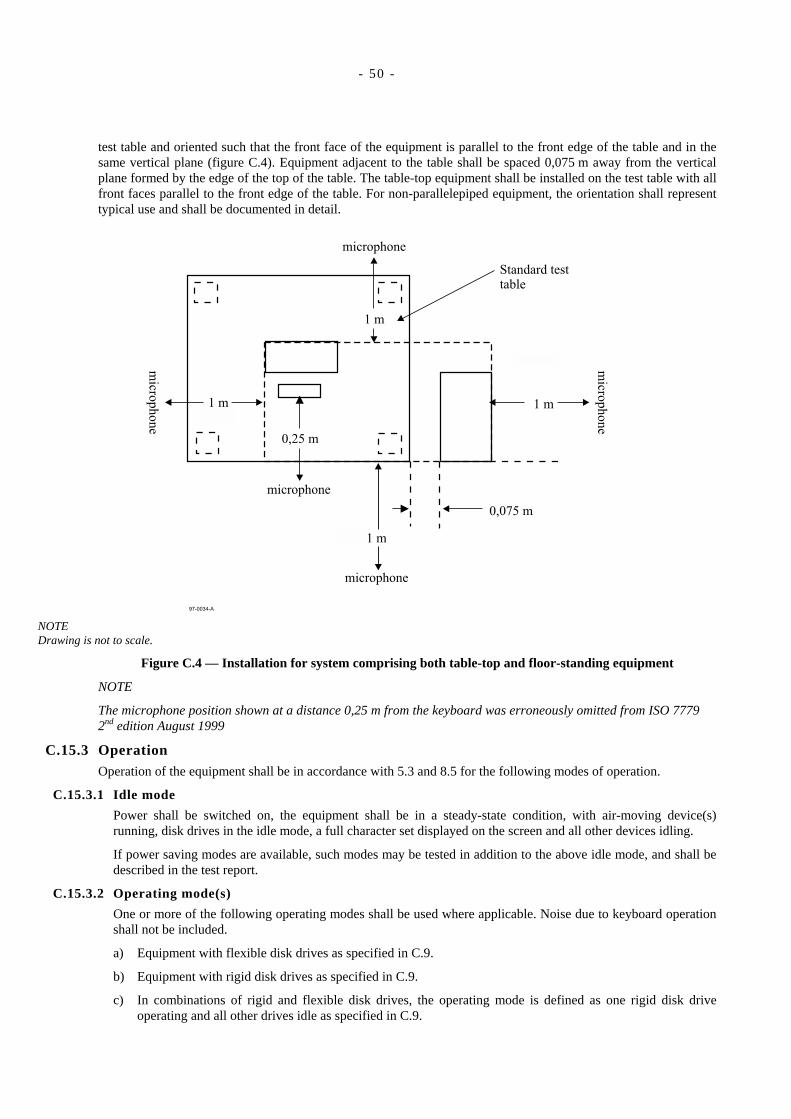
- 50 -
test table and oriented such that the front face of the equipment is parallel to the front edge of the table and in thesame vertical plane (figure C.4). Equipment adjacent to the table shall be spaced 0,075 m away from the verticalplane formed by the edge of the top of the table. The table-top equipment shall be installed on the test table with allfront faces parallel to the front edge of the table. For non-parallelepiped equipment, the orientation shall representtypical use and shall be documented in detail.
microphone
0,075 m
microphone
0,25 m
97-0034-A
micro
ph
on
e
1 m
microphone
1 m
1 m
micro
ph
on
e
1 m
Standard testtable
NOTEDrawing is not to scale.
Figure C.4 — Installation for system comprising both table-top and floor-standing equipment
NOTE
The microphone position shown at a distance 0,25 m from the keyboard was erroneously omitted from ISO 77792nd edition August 1999
C.15.3 OperationOperation of the equipment shall be in accordance with 5.3 and 8.5 for the following modes of operation.
C.15.3.1 Idle mode
Power shall be switched on, the equipment shall be in a steady-state condition, with air-moving device(s)running, disk drives in the idle mode, a full character set displayed on the screen and all other devices idling.
If power saving modes are available, such modes may be tested in addition to the above idle mode, and shall bedescribed in the test report.
C.15.3.2 Operating mode(s)
One or more of the following operating modes shall be used where applicable. Noise due to keyboard operationshall not be included.
a) Equipment with flexible disk drives as specified in C.9.
b) Equipment with rigid disk drives as specified in C.9.
c) In combinations of rigid and flexible disk drives, the operating mode is defined as one rigid disk driveoperating and all other drives idle as specified in C.9.
- 51 -
d) Equipment with magnetic tape units as specified in C.8.
e) Equipment with built-in character and line printers as specified in C.3; equipment with page printers asspecified in C.16.
f) Other types of equipment, as required.
C.15.4 Measurement durationThe time-averaged sound pressure level shall be measured for at least the duration specified in 6.7.2 or 7.7.2.
C.16 Equipment category: Page printersC.16.1 Description
This category covers equipment which produces printed output from computers, the noise output of which isindependent of what is printed on the page. Such equipment may have peripheral equipment such as envelopefeeders, sorters, and special paper feeders. It may print single-sided or two-sided output.
C.16.2 InstallationC.16.2.1 General
Floor-standing printers shall be installed on the hard reflecting floor. Printers which are normally placed on aspecial stand or table shall be installed on such a stand or table on the reflecting floor. Printers which are placedon a normal table or desk and which take paper from, or stack paper on, the floor, shall, if possible, be placed inthe centre of the top plane of the standard test table, using the floor to support the paper. For such measurementsaccording to clause 7 the measurement surface terminates on the reflecting floor.
Table-top printers, which do not use the floor for the paper supply or exit stack, shall be placed on the hardreflecting floor for measurements according to clause 6 or 7 and on the standard test table for measurementsaccording to clause 8.
C.16.2.2 Paper
The paper to be used shall be in accordance with the machine manufacturer's instructions. If there are no suchinstructions, either single sheets of paper of grammage 70 g/m2 to 80 g/m2, or continuously folded or rolledstationery of grammage 50 g/m2 to 60 g/m2 shall be used. Paper dimensions shall be typical of normal use andshall be described in the test report. For special applications (e.g. when the material to be printed is a label or anenvelope) the material shall be typical of customer usage and described in the test report).
Paper storage and unpacking shall be carried out in accordance with manufacturer's instructions. If there are nosuch instructions, paper shall have been stored unpacked and exposed to the environmental conditions specifiedin 6.3.2 for at least 24 h immediately prior to the test.
C.16.3 OperationC.16.3.1 Idle mode
The power shall be switched on and the printer shall be ready for printing.
NOTEIf the page printer has both standby and ready modes, the idle mode corresponds to the standby mode.
C.16.3.2 Operating mode (Print mode)
A print job (consisting of a text pattern) shall be sent to the printer such that it will print at its rated speed.
C.16.3.2.1 Single-sheet printers
Operation of such printers shall comprise the continuous printing of one side of single sheets for at least threesheets. If printing on both sides of sheets is available, this mode shall also be measured. The mode having thehigher A-weighted sound power level shall be reported. Operation shall be performed for the requiredmeasurement duration.
C.16.3.2.2 Continuous-form printers
Operation of such printers shall comprise the continuous printing of at least three pages of folded stationeryor a length of 2 m for rolled stationery.
- 52 -
C.16.3.2.3 Operation cycle with features
When a printing system combines several features, a full system operation cycle shall comprise the use ofeach of the features at least once as described under the respective operation cycle.
a) Sorter
The sorting operation shall start with an empty sorter. An operation cycle shall comprise the sorting of onepage in one bin. Pages printed during additional cycles shall be sorted into consecutive bins.
b) Stacking
If the printer is equipped with an accessory or integral mechanism to separate jobs generated sequentially,an operation cycle shall comprise two jobs and print one page for each of them.
c) Auxiliary equipment
If the printer is supplied with auxiliary equipment (e.g. a mechanism for cutting continuous forms), thetests shall be carried out with and without the use of such equipment in the operation cycle.
C.16.4 Measurement durationFor each set-up the time-averaged sound pressure level shall be measured, for at least the duration specified in6.7.2 or 7.7.2, for a minimum of three operation cycles for single-sheet printers (C.16.3.2.1) and for one operationcycle for continuous-form printers (C.16.3.2.2) and for at least one operation cycle with auxiliary features(C.16.3.2.3).
C.17 Equipment category: Self-service automatic teller machinesC.17.1 Description
Equipment of this category is mainly used in banking environments and provides various services to customers,such as cash dispense, funds transfer between accounts, account balance inquiry, balance statement issuing andenvelope deposit.
Depending on the purpose of the equipment, a variety of different functions can be performed and combined in onemachine. Typical examples for operating modes are specified in C.17.3; it is not assumed that these conditionsapply to all cases, therefore, the test conditions used shall be described in the test report.
C.17.2 InstallationThe equipment shall be installed in accordance with the relevant clauses of this Standard. For the purposes ofreporting A-weighted emission sound pressure levels in accordance with ECMA-109, the bystander positions areapplicable.
C.17.3 OperationC.17.3.1 Idle mode
The power shall be switched on and the equipment shall be ready for use.
C.17.3.2 Operating mode
The operating mode which is typical for average customer usage shall be defined and reported. For someequipment, examples are defined as follows.
a) Money dispenser
Operation comprises card insertion, key-in personal identification number (PIN), task selection (e.g. cashissue), selection of amount of money, issue card, open cash gate, issue cash, issue receipt and close cash gate.
b) Passbook operation
Operation comprises
insert passbook, read magnetic stripe data, key-in PIN, print one line in passbook, write and verifymagnetic stripe data and issue passbook, or
insert passbook, read magnetic stripe data, key-in PIN, task selection (e.g. cash issue), selection ofamount, write and verify magnetic stripe data, issue passbook and issue cash.
- 53 -
c) Banking information print-out
Operation comprises check card insertion, key-in PIN, task selection (e.g. statement of account), issue card,print output and issue output.
d) Cash envelope deposit
Operation comprises card insertion, key-in PIN, task selection (e.g. cash deposit), key-in amount of deposit,insert envelope into depository device, remove card and receipt.
C.17.4 Measurement durationThe time-averaged sound pressure level shall be measured for at least the duration specified in 6.7.2 or 7.7.2. Forthe operating mode, an average value shall be determined for at least three typical transactions, during whichmanual access may be needed, which however shall not be intentionally delayed.
C.18 Equipment category: Enclosures or rack systemsC.18.1 Description
This category covers systems comprising several similar or different system sub-assemblies which are installed in arack or enclosure. The sub-assemblies can have different configurations as required by the user to meet specificrequirements. The sub-assemblies may be self-contained with their own power supplies and cooling assemblies, ormay rely on power supplies and cooling assemblies installed separately in the rack or enclosure.
NOTEThis equipment category does not include sub-assemblies not installed in a rack or enclosure.
C.18.2 InstallationThe constituent sub-assemblies of the system may be tested in the rack or enclosure and reported individually, orthe system may be tested and reported as a whole for a specified configuration.
When sub-assemblies are tested individually in the rack or enclosure, they shall be installed in the positionspecified in the rack or enclosure manufacturer's installation manual with all other positions either empty withblanking plates in place and/or filled with unpowered sub-assemblies. Only the noise of the sub-assembly shall bereported together with its position in the rack or enclosure. All necessary external devices such as power suppliesand cooling assemblies housed separately in the rack or enclosure shall be considered as sub-assemblies andmeasured and reported accordingly.
For configurations tested as complete systems the sub-assemblies shall be installed in the positions specified in therack or enclosure manufacturer's installation manual for a given configuration and shall be described in the testreport.
The installation conditions for the rack or enclosure systems are as specified in 5.1, 8.5 and the relevant clauses ofthis annex.
C.18.3 OperationOperation of the equipment shall be in accordance with 5.3 for the following modes of operation.
C.18.3.1 Idle mode
The power shall be switched on, and all sub-assemblies shall be in idle mode ready to receive command signalsfrom the system CPU.
C.18.3.2 Operating mode
One or more of the following operating modes should be used as applicable:
a) rigid and flexible disk drives as specified in C.9;
b) magnetic tape units as specified in C.8;
c) built-in character and line printers as specified in C.3; equipment with page printers as specified in C.16;
d) other types of equipment as required.
- 54 -
NOTEMeasurements on individual disk drives should be made at the seek rate typical of the multiple-driveconfiguration if system limitations do not allow the seek rate specified in C.9. This is necessary so as not tooverestimate the system noise emission levels as calculated in accordance with C.18.5 from individualmeasurements.
C.18.4 Measurement durationThe time-averaged sound pressure level shall be measured for at least the duration specified in 6.7.2 or 7.7.2 and asfurther required in this annex for the operation of the sub-assemblies.
C.18.5 Calculation of the system A-weighted sound power level and system A-weighted emissionsound pressure level from sub-assembly sound levelsThe system A-weighted emission sound power level shall be calculated using the following equation:
( )dB
1
A1,0
sysA, 10lg10 ∑=
=n
i
iWL
WL
where
LWA,sys is the system A-weighted sound power level, in decibels;
LWAi is the A-weighted sound power level of the i-th sub-assembly installed in a rack or enclosure;
n is the number of sub-assemblies.
The system A-weighted emission sound pressure level shall be calculated using the following equation:
dB101
A1,0
sysA, lg10 ∑=
=n
i
ipL
pL
where
LpA,sys is the system A-weighted emission sound pressure level, in decibels;
LpAi is the A-weighted emission sound pressure level of the i-th sub-assembly installed in a rack orenclosure;
n is the number of sub-assemblies installed and tested.
C.18.6 Calculation of A-weighted sound power level and A-weighted emission sound pressurelevel for low noise level sub-assembliesIn some cases the noise level of sub-assemblies may be within 6 dB of the background noise level which wouldpreclude an accurate value if measured individually. In this case enough identical sub-assemblies shall be testedand measured in the enclosure, so that the noise level of the n sub-assemblies is sufficiently greater than thebackground noise level (it may be convenient to test the maximum number allowed).
The sub-assembly A-weighted sound power level shall be calculated from the following equation:
LWA,s = LWA,sn − 10 lg n dB
where
LWA,s is the averaged individual sub-assembly A-weighted sound power level, in decibels;
LWA,sn is the total A-weighted sound power level for n identical installed sub-assemblies, in decibels;
n is the number of sub-assemblies installed and tested.
The sub-assembly A-weighted emission sound pressure level shall be calculated from the following equation:
- 55 -
LpA,s = LpA,sn − 10 lg n dB
where
LpA,s is the sub-assembly A-weighted emission sound pressure level, in decibels;
LpA,sn is the total A-weighted sound pressure level for n identical installed sub-assemblies, in decibels;
n is the number of sub-assemblies installed and tested.
C.19 Equipment category – CD-and DVD-ROM drivesC.19.1 Description
Equipment for reading electronic information from a rotating read-only optical disk (for example, CD-ROM orDVD-ROM) or other optical media operated in a substantially sequential access manner.
C.19.2 InstallationC.19.2.1 General
Installation shall be according to 5.1 and 8.5 of this Standard. A drive which forms part of a personal computeror rack mounted equipment shall be installed according to C.15 or C.18 as appropriate. A drive which is testedas a sub-assembly shall be installed as a sub-assembly per 5.1.1.6.
C.19.2.2 Media
The unbalance factor of test media shall be in the range of 2,5 g-mm ± 10 %. For this purpose, a dedicated testmedia which has the nominal unbalance factor specified immediately above should be used.
NOTEThis media requirement is based on several considerations.
C.1 requires that the operation be “typical of average end use”. Conditions are to be “specified with a view tofacilitate the operation of the equipment and to enhance the reliability of the acoustical measurements”.
A statistical study of media unbalance of fifty CD-ROM disks was conducted. The sample included disks used foraudio, video, games and reference material. The unbalance was found to range from 0,75 g-mm to 8,2 g-mm,and to have an average equal to 2,46 g-mm.
Systematic measurements were made of more than ten system configurations using three different notebook typecomputers and having CD-ROM drives ranging from 8x to 24x speed. Four kinds of media were used, havingdifferent unbalance (i.e., 3 g-mm, 5 g-mm, 7,5 g-mm and 10 g-mm). Results showed a 10 dB range of soundpower level due to unbalance alone, therefore reliability of measurements requires specification of unbalance.Moreover, some of the higher speed drives, such as 20x speed, could not operate at the higher unbalance levels,but had to slow down their rotational speed to read information on the media correctly. This slowing down isnot typical of average end use.
The disk unbalance of 2,5 g-mm ± 10% is specified as “typical of average end use” and is also consistent withreliable acoustical measurements, since this degree of unbalance avoids causing some drives to slow down.
C.19.3 OperationC.19.3.1 Idle mode
Except for short duration transients, idle modes are considered non-rotational and inaudible. Thereforemeasurement of the idle mode is not required.
C.19.3.2 Operating mode
For units having a single drive, the drive shall be operating as described below.
For units with multiple drives the number of drives that are simultaneously operable by the host CPU shall beoperated as specified below. All other drives shall be in the idle mode, typical of normal use for the system.
Sequential read at the inner radius of the disk (or media) such that the disk spins continuously at its fastestnormal rotational speed. Repeat the above read process until the measurement duration specified below elapses.

- 56 -
C.19.4 Measurement durationThe time-average sound pressure level shall be measured for at least the duration specified in 6.7.2 or 7.7.2.
- 57 -
Annex D(informative)
Identification of prominent discrete tones
D.1 GeneralThis annex describes a procedure for determining whether or not noise emissions include prominent discrete tones.
The method of this annex is primarily applicable to operator-attended equipment. However, the method may beapplied to other equipment that is intended to be installed in low-noise areas.
D.2 BackgroundA discrete tone which occurs together with broadband noise is partially masked by that part of the noise contained in arelatively narrow frequency band, called the critical band, that is centred at the frequency of the tone. Noise atfrequencies outside the critical band does not contribute significantly to the masking effect. The width of a criticalband is a function of frequency (see D.6). In general, a tone is just audible when the sound pressure level of the tone isabout 4 dB below the sound pressure level of the masking noise contained in the critical band centred around the tone.This is the threshold of audibility. For the purposes of this annex, a discrete tone is defined as being prominent if thesound pressure level of the tone exceeds the sound pressure level of the masking noise in the critical band by 6 dB.This corresponds, in general, to a tone being prominent when it is more than 10 dB above the threshold of audibility.
Declaration of product emissions in accordance with ECMA-109 offers the option of stating whether or not there areprominent discrete tones in the emissions of a product, as determined by this Standard. This annex defines the onlymethod for identifying prominent discrete tones that is acceptable as part of this Standard or for declaration inaccordance with ECMA-109.
NOTEThere are, however, other methods of determining the prominence of tonal sound. Other methods do not necessarilyproduce the same decision as to whether a particular spectrum contains a prominent discrete tone. ANSI S1.13 [5]describes two procedures for informational purposes in Appendix A. The "Tone-to-Noise Ratio" is essentiallyconsistent with the procedure of this ECMA Standard including the correction for the presence of a second tone. (ISO7779 2nd edition August 1999 erroneously states that ANSI S1.13 does not correct for the presence of a second tone.)The "Prominence Ratio" is a relatively new procedure, which compares all the sound energy in the Zwicker criticalband centred on a tone with the total energy in immediately adjacent critical bands. This method may be consideredby ISO TC43/SC1/WG23 as a replacement for the present method in a future revision of ISO 7779. The workinggroup would welcome information on experience with use of the Prominence Ratio method, both its ease ofimplementation and its correlation with subjective judgement, as compared with the method specified herein.
CAUTION:In the method described in this annex a difficulty arises when a tone exists within, but near the upper or lower limit of,the frequency range of interest. One needs a measurement of masking noise outside this stated range to determinewhether the tone is prominent, but such a measurement outside the range does not have well-defined measurementprecision, calibration tolerance, reverberant sound limits, or background noise limits.
This annex permits measurement outside the stated frequency range of interest for the purposes of determiningwhether an audible tone is prominent. Consistent with ISO 11201, no correction should be made for background noiseor reverberant sound.
D.3 Microphone positionIf the equipment has an operator position, the measurements should be performed at that position. If there is more thanone operator position, the measurements described below should be performed at the operator position with thehighest A-weighted sound pressure level.
If the equipment has no operator position, the measurements should be performed at the bystander position with thehighest A-weighted emission sound pressure level and at all other bystander positions having A-weighted emission

- 58 -
sound pressure levels within 0,5 dB of it to determine the tone-to-noise ratios, ∆L (see D.5 ).
For sub-assemblies which will be installed in table top products, the sub-assembly should be installed in the centre ofa standard test table and isolated from the surface by three or four elastomeric feet, approximately 12 mm high. Forsub-assemblies which will be installed in other enclosures or racks, the sub-assembly should be installed as in 5.1.7.For sub-assemblies which will be installed in equipment with a defined operator position, this operator position shouldbe used for the sub-assembly measurement, otherwise, the measurements should be performed as described in thepreceding paragraph.
D.4 InstrumentationThe instruments should meet the requirements of 7.4. However, the procedure of this annex requires measurement of
the sound pressure level of the tone,
the sound pressure level of secondary tones and the critical band, and
the sound pressure level of the noise in the critical band centred at the frequency of the tone.
The instrumentation used should be capable of determining these levels with a tolerance of 1 dB. Commerciallyavailable or specially designed analog or digital instruments may be used to measure the levels directly, or raw datamay be acquired and then processed by a digital computer. To measure the sound pressure levels, a narrow bandanalysis should be performed with the analyser frequency bandwidth resolution less than 1 % of the frequency of thetone. No weighting function (e.g. A-weighting) should be applied to the analyser input signal. A Fast FourierTransform (FFT) analyser is the preferred type of instrumentation. If an FFT analyser is used, the FFT analysis shoulduse r.m.s. averaging, a Hanning time window function and a sufficient number of averages to provide an analysis timesatisfying the requirements of 7.7.2.
D.5 Measurement procedureAural examination of the noise emitted by the equipment under test should be made at the microphone position. It isrecommended that both of the following listening tests be conducted in addition to the measurement procedure furtherbelow.
a) Conduct a general listening test without any comparison to reference tones. If the equipment under test soundstonal, the measurement procedure below should be performed for any such tones and those identified asprominent according to the criterion in D.7.
b) Perform the measurement procedure below on all tones that appear to be prominent in the narrow-band analysis.For any tones exceeding the tone-to-noise criterion in D.7, play a sine-wave (having the same frequency as thetone in question) over a headset or loudspeaker and compare it to the sound from the product, noting whether ornot a tone at the sine-wave frequency is audible in the product sound emissions.
In cases where there is doubt as to whether audible tones are present or not, other, more objective, evidence should besought (such as a narrow-band analysis of the noise).
The sound pressure level (in decibels) of the discrete tone Lt, and the sound pressure level (in decibels) of the maskingnoise Ln, exclusive of the tone, contained within the critical band centred at the frequency of the tone, should bedetermined for the same mode(s) of operation and measurement conditions as used for the measurements in 8.7. Whenbandpass filters are used and the band sound pressure levels are measured, care shall be taken to ensure that themeasurement of the masking noise is not corrupted by the tone, and vice versa. The level Lt should be taken as thesound pressure level contained in the narrow band that just delineates the tone. The value of Lt may be determined bybracketing the data points that define the tone with the analyser’s band cursors, and then computing the power in thisband. If the width of the frequency band selected to bracket the tone is greater than 15 % of the width of the criticalband, the measurement should be repeated with a smaller resolution bandwidth. If this continues to produce a signalfor which the bracketed tone's bandwidth is greater than 15 % of the critical band, then the tone should be bracketedby a band centred on the frequency of the tone whose width is 15 % of the critical band; the filter bandwidth used todetermine the level of the discrete tone should not exceed 15 % of the critical bandwidth as defined in D.6.
The tone-to-noise ratio ∆L (in decibels) is then taken as (Lt – Ln).
- 59 -
NOTE 1Since the tone-to-noise ratio is a difference in levels, absolute calibration of the instrumentation is not necessary;relative levels may be used.
NOTE 2When working with sound pressure quantities instead of levels, the mean square sound pressure of the tone Wt, andthe mean square sound pressure of the masking noise Wn, are determined, and the tone-to-noise ratio is taken as(Wt/Wn). Since this is a dimensionless ratio, absolute calibration of the instrumentation is not necessary.
D.6 Critical bandwidthsThe width of the critical band ∆fc, centred at any frequency f, can be calculated from the following equation (seereference [3]):
∆ fc = 25,0 + 75,0 [1,0 + 1,4( f /1000)2]0,69
EXAMPLE ∆ fc = 162,2 Hz for f = 1 kHz
For the purpose of determining the value of Ln, the critical band is modelled as a rectangular filter with centrefrequency f0, lower band edge frequency f1, and upper band edge frequency f2, where
( ) 5,0210 fff =
and
f2 = f1 + ∆ fc
D.7 Prominent discrete tonesA discrete tone is identified as prominent if and only if
(Lt – Ln) > 6,0 dB
and the discrete tone is audible according to at least one of the two listening tests in D.5.
NOTEWhen working with sound pressure quantities instead of levels, the above criterion corresponds to (Wt/Wn) > 4,0.
D.8 Multiple tones in a single critical bandThe noise emitted by a machine may contain many tones; several of these may fall within a single critical band. If oneor more tones is audible, the procedure above is followed for each tone with the following differences. Let the tone inany critical band having the largest sound pressure level Lt be identified as the primary tone, and denote its frequencyas fp. For the critical band centred on the primary tone, identify the second strongest tone as the secondary tone anddenote its frequency fs.
If the secondary tone is sufficiently close in frequency to the primary tone, then the two are considered to be perceivedas a single discrete tone and the prominence is determined by combining their tonal energy. The proximity criterion isgiven by the following equation, which approximates figure 13 of reference [4]. Within the difference | fs – fp | < fd
two discrete tones are not distinguished as separate, where
( )[ ] 8,1212lg2,1
1021d
ff ×= for 88<f<1000
If the proximity criterion is met, then the energy of the secondary tone should be removed from the masking noise andadded to the energy of the primary tone before calculating tone-to-noise ratio. (For frequencies exceeding 1 kHz, fd
exceeds half the width of the Zwicker critical band, so the criterion is always met).
If the proximity criterion is not met, then the tones are considered to be perceived as discrete and are treated
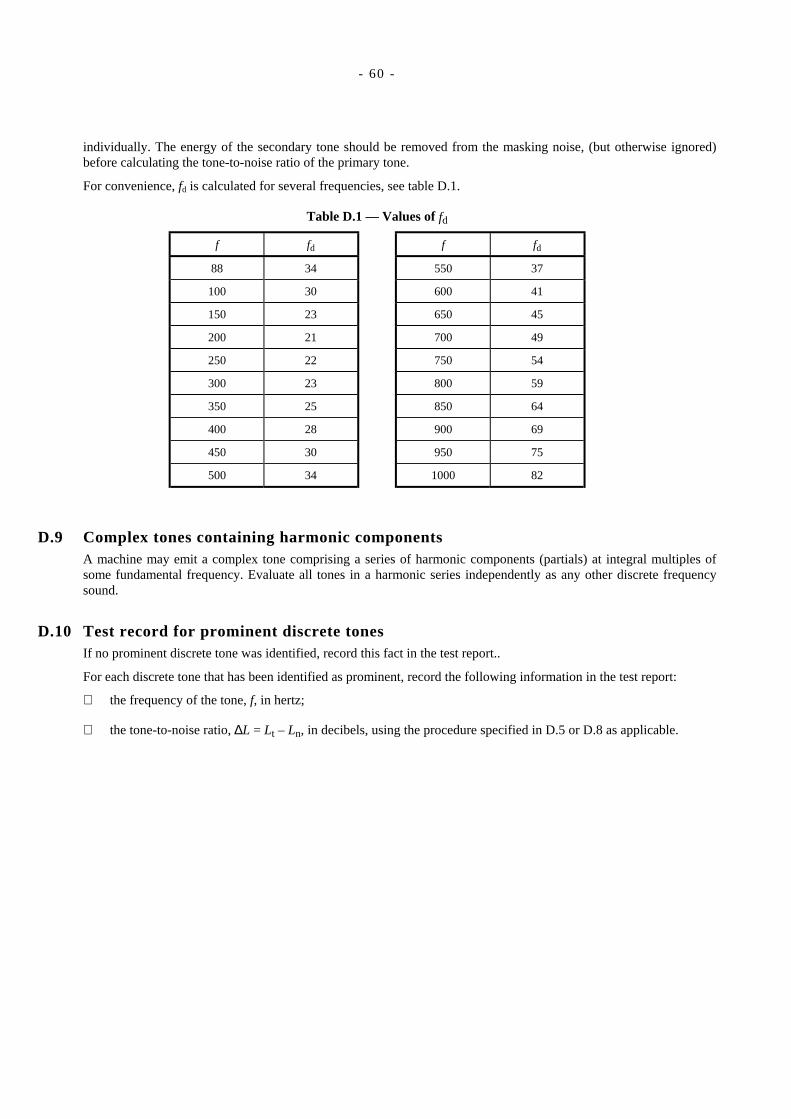
- 60 -
individually. The energy of the secondary tone should be removed from the masking noise, (but otherwise ignored)before calculating the tone-to-noise ratio of the primary tone.
For convenience, fd is calculated for several frequencies, see table D.1.
Table D.1 — Values of fd
f fd f fd
88 34 550 37
100 30 600 41
150 23 650 45
200 21 700 49
250 22 750 54
300 23 800 59
350 25 850 64
400 28 900 69
450 30 950 75
500 34 1000 82
D.9 Complex tones containing harmonic componentsA machine may emit a complex tone comprising a series of harmonic components (partials) at integral multiples ofsome fundamental frequency. Evaluate all tones in a harmonic series independently as any other discrete frequencysound.
D.10 Test record for prominent discrete tonesIf no prominent discrete tone was identified, record this fact in the test report..
For each discrete tone that has been identified as prominent, record the following information in the test report:
the frequency of the tone, f, in hertz;
the tone-to-noise ratio, ∆L = Lt – Ln, in decibels, using the procedure specified in D.5 or D.8 as applicable.
- 61 -
Annex E(informative)
Detection of impulsive sound pressure levels
E.1 GeneralThis annex provides an objective test method for determining whether the noise emissions are impulsive in character,viz. are of short duration and relatively high amplitude.
This method is primarily applicable to operator-attended equipment with non-steady noise emissions.
This method is based on ISO 11201:1995, annex A, paragraph 1, with modifications for consistency with other partsof this Standard.
E.2 InstrumentsThe instruments should meet the requirements of 8.4. The sound level meter should be equipped with thetimeweighting I.
E.3 Microphone positionIf the equipment has an operator position, the measurements should be performed at the operator position. If there ismore than one operator position, the measurements described below should be performed at the operator position withthe highest A-weighted emission sound pressure level.
If the equipment has no operator position, the measurements should be performed at the bystander position with thehighest A-weighted emission sound pressure level and at all other bystander positions having A-weighted emissionsound pressure levels within 0,5 dB of it to determine the impulsive parameter ∆LI identified below.
For sub-assemblies which will be installed in table top products, the sub-assembly should be installed in the centre ofa standard test table and isolated from the surface by three or four elastomeric feet, approximately 12 mm high. Forsub-assemblies which will be installed in other enclosures or racks, the sub-assembly should be installed as in 5.1.7.For sub-assemblies which will be installed in equipment with a defined operator position, this operator position shouldbe used for the sub-assembly measurement, otherwise, the bystander position having the highest A-weighted emissionsound pressure level should be used.
E.4 Measurement procedureAural examination of the noise emitted by the equipment under test should be made at the microphone positiondescribed above. If the noise emissions are perceived to include impulsive sound, the following test should beperformed.
The time averaged A-weighted impulse sound pressure level, LpAI, and A-weighted sound pressure level, LpA, shouldbe measured for the same mode(s) of operation, measurement conditions, time duration and time averaging as used forthe measurements in 8.7. The difference in decibels between the time averaged A-weighted impulse sound pressurelevel, LpAI, and the A-weighted sound pressure level, LpA, should be obtained. The difference (LpAI − LpA) is theimpulsive parameter, ∆LI. If ∆LI > 3 dB the noise is considered to be impulsive.
The time averaged A-weighted impulse sound pressure level, LpAI, is used only to determine whether the noiseemissions are impulsive. The impulsive parameter ∆LI is zero for steady, non-impulsive noises, and increases in valuewith increasing impulsiveness of the noise.
If the impulse sound level is recorded, the d.c. level output of the impulse sound level meter should be used. Thedynamic response of the recorder should be such that it will respond to at least 90 % of full scale for a rectangularpulse the duration of which is 0,2 s.

- 62 -
E.5 Test record for impulsive sound pressure levelsIf no impulsive sound pressure levels were identified, record the fact. If impulsive sound pressure levels wereidentified, record that fact in the test record and the value of the impulsive parameter, ∆LI.
- 63 -
Annex F(informative)
Bibliography
[1] Geräuschemission von Geräten der Büro- und Informationstechnik. Schriftenreihe der Bundesanstalt für ArbeitsschutzFb 481, Bd. 1 Wirtschaftsverlag NW, Verlag für neue Wissenschaft GmbH, Germany.
[2] Zwicker, E. and Terhardt, E., Analytical expression for critical-band rate and critical bandwidth as a function offrequency. Journal of Acoustical Society of America, 68(1), 1980, pp. 1523-1525.
[3] Plomp, R. Journal of Acoustical Society of America, 36 1964, pp. 1628-1636.

..
Free printed copies can be ordered from:
ECMA114 Rue du RhôneCH-1204 GenevaSwitzerland
Fax: +41 22 849.60.01Internet: [email protected]
Files of this Standard can be freely downloaded from the ECMA web site (www.ecma.ch). This site gives full information onECMA, ECMA activities, ECMA Standards and Technical Reports.

ECMA
114 Rue du RhôneCH-1204 GenevaSwitzerland
See inside cover page for obtaining further soft or hard copies.
Related Documents