EURASIP Journal on Applied Signal Processing 2005:11, 1712–1724 c 2005 Uwe Trautwein et al. Measurement-Based Performance Evaluation of Advanced MIMO Transceiver Designs Uwe Trautwein MEDAV GmbH, Gr¨ afenberger Strasse 32-34, 91080 Uttenreuth, Germany TeWiSoft GmbH, Ehrenbergstrasse 11, 98693 Ilmenau, Germany Email: [email protected] Christian Schneider Institute of Communications and Measurement Engineering, Ilmenau University of Technology, 98684 Ilmenau, Germany Email: [email protected] Reiner Thom ¨ a Institute of Communications and Measurement Engineering, Ilmenau University of Technology, 98684 Ilmenau, Germany Email: [email protected] Received 29 February 2004; Revised 14 January 2005 This paper describes the methodology and the results of performance investigations on a multiple-input multiple-output (MIMO) transceiver scheme for frequency-selective radio channels. The method relies on offline simulations and employs real-time MIMO channel sounder measurement data to ensure a realistic channel modeling. Thus it can be classified in between the performance evaluation using some predefined channel models and the evaluation of a prototype hardware in field experiments. New as- pects for the simulation setup are discussed, which are frequently ignored when using simpler model-based evaluations. Example simulations are provided for an iterative (“turbo”) MIMO equalizer concept. The dependency of the achievable bit error rate performance on the propagation characteristics and on the variation in some system design parameters is shown, whereas the an- tenna constellation is of particular concern for MIMO systems. Although in many of the considered constellations turbo MIMO equalization appears feasible in real field scenarios, there exist cases with poor performance as well, indicating that in practical applications link adaptation of the transmitter and receiver processing to the environment is necessary. Keywords and phrases: MIMO systems, channel modeling, channel sounding, turbo equalization, link-level simulations. 1. INTRODUCTION MIMO transmission schemes are attractive candidates for the new air interfaces of wireless networks beyond 3G. This is due to the expected increase in spectrum efficiency, which results from a simultaneous transmission of multiple data streams from different antenna elements [1]. The transmit- ted signals are intentionally not orthogonal in any of the con- ventional communication signal dimensions, that is, by time, frequency, or code. Conceptually, the multipath propagation of the radio channel gives rise to different spatiotemporal sig- natures for the different transmit data streams, which per- mits a receiver equipped with multiple antennas to separate those data streams from the received signal mixture. Keeping this in mind, it is not really surprising that the performance This is an open access article distributed under the Creative Commons Attribution License, which permits unrestricted use, distribution, and reproduction in any medium, provided the original work is properly cited. of a MIMO system will strongly depend on the radio chan- nel conditions. A key question for a system implementation is, therefore, do we find practically feasible schemes that are sufficiently robust for this task? Or somewhat related, what specific features are required for a practical MIMO system to work reliably under a wealth of various propagation condi- tions? This paper approaches those questions by describing a realistic simulation methodology which is focused to gain insights into propagation-related effects of a specific MIMO transceiver design example. The idea is to use the results of double-directional real-time channel sounding experiments [2] for MIMO link-level simulations. Thus, the proposed method fills the gap between the conclusions obtained by idealized simulations based on some channel model and the results of using a prototype hardware in field experiments. The advantages of the measurement-based offline simulation in comparison with the prototype experiments are higher flexibility, lower costs, and an improved perception of the

Welcome message from author
This document is posted to help you gain knowledge. Please leave a comment to let me know what you think about it! Share it to your friends and learn new things together.
Transcript
EURASIP Journal on Applied Signal Processing 2005:11, 1712–1724c© 2005 Uwe Trautwein et al.
Measurement-Based Performance Evaluationof Advanced MIMO Transceiver Designs
Uwe TrautweinMEDAV GmbH, Grafenberger Strasse 32-34, 91080 Uttenreuth, Germany
TeWiSoft GmbH, Ehrenbergstrasse 11, 98693 Ilmenau, GermanyEmail: [email protected]
Christian SchneiderInstitute of Communications and Measurement Engineering, Ilmenau University of Technology, 98684 Ilmenau, GermanyEmail: [email protected]
Reiner ThomaInstitute of Communications and Measurement Engineering, Ilmenau University of Technology, 98684 Ilmenau, GermanyEmail: [email protected]
Received 29 February 2004; Revised 14 January 2005
This paper describes the methodology and the results of performance investigations on a multiple-input multiple-output (MIMO)transceiver scheme for frequency-selective radio channels. The method relies on offline simulations and employs real-time MIMOchannel sounder measurement data to ensure a realistic channel modeling. Thus it can be classified in between the performanceevaluation using some predefined channel models and the evaluation of a prototype hardware in field experiments. New as-pects for the simulation setup are discussed, which are frequently ignored when using simpler model-based evaluations. Examplesimulations are provided for an iterative (“turbo”) MIMO equalizer concept. The dependency of the achievable bit error rateperformance on the propagation characteristics and on the variation in some system design parameters is shown, whereas the an-tenna constellation is of particular concern for MIMO systems. Although in many of the considered constellations turbo MIMOequalization appears feasible in real field scenarios, there exist cases with poor performance as well, indicating that in practicalapplications link adaptation of the transmitter and receiver processing to the environment is necessary.
Keywords and phrases: MIMO systems, channel modeling, channel sounding, turbo equalization, link-level simulations.
1. INTRODUCTION
MIMO transmission schemes are attractive candidates forthe new air interfaces of wireless networks beyond 3G. Thisis due to the expected increase in spectrum efficiency, whichresults from a simultaneous transmission of multiple datastreams from different antenna elements [1]. The transmit-ted signals are intentionally not orthogonal in any of the con-ventional communication signal dimensions, that is, by time,frequency, or code. Conceptually, the multipath propagationof the radio channel gives rise to different spatiotemporal sig-natures for the different transmit data streams, which per-mits a receiver equipped with multiple antennas to separatethose data streams from the received signal mixture. Keepingthis in mind, it is not really surprising that the performance
This is an open access article distributed under the Creative CommonsAttribution License, which permits unrestricted use, distribution, andreproduction in any medium, provided the original work is properly cited.
of a MIMO system will strongly depend on the radio chan-nel conditions. A key question for a system implementationis, therefore, do we find practically feasible schemes that aresufficiently robust for this task? Or somewhat related, whatspecific features are required for a practical MIMO system towork reliably under a wealth of various propagation condi-tions?
This paper approaches those questions by describing arealistic simulation methodology which is focused to gaininsights into propagation-related effects of a specific MIMOtransceiver design example. The idea is to use the results ofdouble-directional real-time channel sounding experiments[2] for MIMO link-level simulations. Thus, the proposedmethod fills the gap between the conclusions obtained byidealized simulations based on some channel model and theresults of using a prototype hardware in field experiments.The advantages of the measurement-based offline simulationin comparison with the prototype experiments are higherflexibility, lower costs, and an improved perception of the
Measurement-Based Performance Evaluation of MIMO Designs 1713
transceiver’s operation, which is primarily due to more effec-tive analysis techniques. The paper does not investigate thedetrimental effects resulting from practical implementationissues, although the proposed simulation method could beextended accordingly.
Many of the proposals for implementing MIMO sys-tems consider only algorithms suitable for frequency-flat fad-ing radio channels [3, 4]. This simplifies the channel mod-eling requirements significantly since only spatial correla-tions of the signals are to be considered. But for the ex-pected high data rates of future mobile communication sys-tems, frequency-selective fading channels are inevitable. TheOFDM approach is frequently adopted in order to convertthe wideband channel into a multitude of frequency-flatchannels. It goes along with this idea that the channel mod-eling is often separated into the spatial and the frequency di-mension, which in general does not reflect reality. Further-more, in an OFDM system, multipath diversity can only begained if the channel coding is explicitly designed to do so[5]. Joint space-time equalization in single-carrier widebandsystems is in contrast inherently capable to exploit multipathdiversity and to simultaneously suppress cochannel interfer-ence [6]. This motivates its consideration also for MIMO sys-tems. Different promising proposals for numerically efficientsignal separation methods for frequency-selective channelsare based on iterative interference cancellation techniques.For example, in [7], the successive detection principle of theBLAST algorithm is extended. Especially for CDMA systems,several optimal [8] and suboptimal [9, 10] concepts for it-erative multiuser receivers can be found. But it seems ques-tionable whether the bandwidth expansion of CDMA sys-tems is a viable option for future wideband systems. In con-trast to this, the combination of parallel soft interference can-cellation, minimum mean square error (MMSE) detection,and soft-input soft-output (SISO) channel decoding leads toan iterative turbo-detection scheme [11] suitable for single-carrier transmission, which is called a turbo MIMO equalizer(TME).
Wideband MIMO receivers depend on the joint spatialand temporal multipath structure at the transmitter (Tx) sideas well as the receiver (Rx) side of the radio link. Hence,evaluating the performance of a wideband MIMO detec-tion scheme by means of simulations requires much moredetailed knowledge and exactness of the channel than con-ventional single-antenna systems or systems with multipleantennas only at one side of the link. This makes high de-mands on an appropriate MIMO channel model, which iscurrently a hot topic in the research. However, the valida-tion of the different proposals is frequently relied on fromthe system design perspective rather abstract benchmark cri-teria, like the channel capacity [12, 13]. The correspondingoutcome of a channel model, which is parameterized to ameasured scenario, is thereto compared with the results fromreal measured data. Although the channel capacity seems tobe the performance criterion par excellence when consider-ing MIMO systems, this does not necessarily imply that agood match in modeling the capacity guarantees a sufficientmatch to model the spatiotemporal channel structure for a
b1(k)
bN (k)
...
Tx
ante
nn
as
. . .
. . .
h11(l)
hM1(l)
h1N (l)
hMN (l)
...
...
...
Rx
ante
nn
as
r1(k)
rM(k)
Rx
proc
essi
ng
v1(k)
vM(k)
. . . . . .
. ..
. ..
Figure 1: System model for MIMO transmission.
particular transceiver signal processing scheme. For this rea-son, a good practice is the validation of new models in termsof the performance results of system simulations. This is pos-sible by comparing the model-based results with the resultsobtained when directly using the data of representative ex-ample environments, which requires that the model be pa-rameterized to the measured data.
The paper is organized as follows. Section 2 describes thesystem model for a wideband MIMO system and presentsa brief summary of the TME-based transceiver concept.Next, the MIMO measurement procedure and the methodsfor measurement-based link-level simulations are described.Simulation results for specific investigations and the connec-tion to propagation analysis results are shown in Section 4.This extends initial results of [14]. Some conclusions aregiven in Section 5.
2. WIDEBAND MIMO SYSTEM
2.1. System model
The TME concept has been derived in [11], based on a pro-posal of an iterative CDMA receiver [9, 15]. This paper dis-cusses its application for generalized MIMO system setups,which comprises a multiuser (MU) setup, a point-to-point(P2P) setup, as well as a multiuser MIMO setup. In order tosimplify the description, the TME-based receiver is assumedat the base station (BS) of a cellular system or at the accesspoint of a wireless local area network (WLAN) system. In theMU setup, the multiple transmit data streams originate fromseveral single-antenna user terminals. The goal of adoptingthe MIMO approach in this setup is to maximize the sys-tem capacity in bps/Hz per radio cell. The P2P setup allowsto maximize the link capacity in bps/Hz for a single link be-tween a user terminal equipped with multiple antennas andthe BS. The multiuser MIMO setup combines both featuresby allowing several user terminals with multiple antennas.Some implications of the different setups on the system de-sign are discussed later. Here, it should only be mentionedthat a coding scheme spanning multiple antennas is obvi-ously only possible if they are located at the same terminal.
The system model for a general wideband MIMO sys-tem with N independent transmit data streams is depicted inFigure 1. The transmit data symbols bn(k) are taken from therespective modulation alphabet with the mean power nor-malized to σ2
b = 1. The radio channel between each pair
1714 EURASIP Journal on Applied Signal Processing
of the M receive and N transmit antennas is modeled bythe complex finite channel impulse response hmn(l) havingL taps. Thus, the receive signal at antenna m can be writtenas
rm(k) =L−1∑l=0
N∑n=1
hmn(l)bn(k − l) + σvvm(k), (1)
where vm(k) are the complex additive white Gaussian noise(AWGN) samples at receive antenna m with variance 1.The channel memory introduces intersymbol interference(ISI) to the transmit symbols, and the multiple simultaneoustransmissions affect each transmit signal by cochannel inter-ference, originating from all other signals. This is also de-noted as multiple-access interference (MAI). For the detec-tion process, the receiver uses a number of spatial and tem-poral receive signal samples which are stacked into one largespace-time (ST) receive signal vector for notational conve-nience,
r(k)
= [r1(k) · · · rM(k) · · · r1(k + L− 1) · · · rM(k + L− 1)]T.
(2)
Likewise, the noise samples are stacked into a vector v(k). Forsimplicity, it is assumed that the number of temporal samplesused for the detection is equal to the channel memory length,that is, all multipath components of a data symbol are cap-tured. In this case, the vector of transmit data symbols con-tributing to r(k) is
b(k) = [b1(k − L + 1) · · · bN (k − L + 1)
· · · b1(k + L− 1) · · · bN (k + L− 1)]T
,(3)
and a compact matrix notation of (1) can be written in theform
r(k) = Hb(k) + σvv(k) (4)
by introducing the ST MIMO channel matrix
H =
H(L− 1) · · · H(0) · · · 0
.... . .
.... . .
...0 · · · H(L− 1) · · · H(0)
, (5)
which is constructed from the spatial channel matrices H(l)for each delay tap l:
H(l) =
h11(l) · · · h1N (l)
.... . .
...hM1(l) · · · hMN (l)
. (6)
For later reference, the ST transmit channel vectors hn areintroduced as
hn =[h1n(0) · · ·hMn(0) · · ·h1n(L− 1) · · ·hMn(L− 1)
]T,
(7)
which are essentially the central N columns of the H matrix.
2.2. Turbo MIMO equalization
In a TME-based single-carrier system, the transmit data sym-bols bn(k) are the result of an independent transmitter pro-cessing for each of the corresponding source bit streams. Asimple convolutional error correcting code is applied, thecoded bits are interleaved and afterwards modulated. Thispaper considers BPSK, QPSK, 8-PSK, and 16-QAM as mod-ulation schemes.
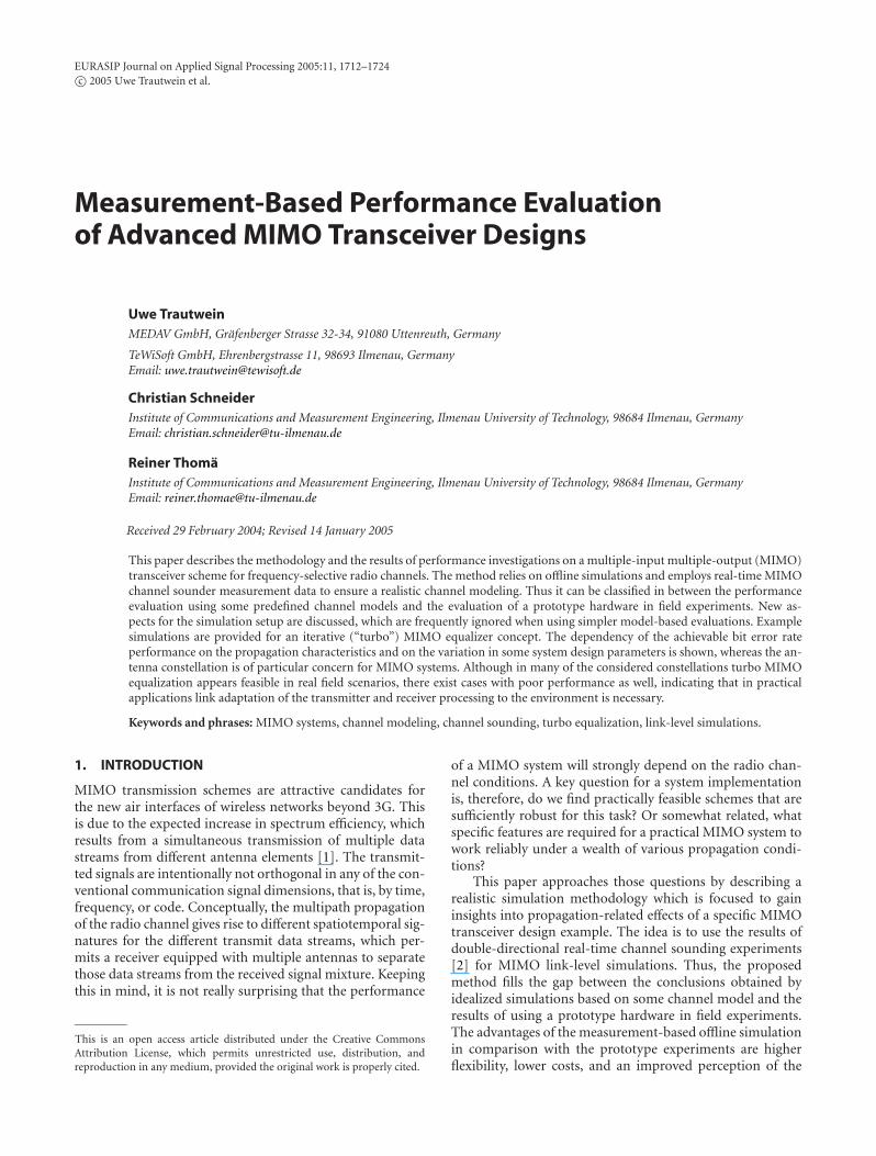
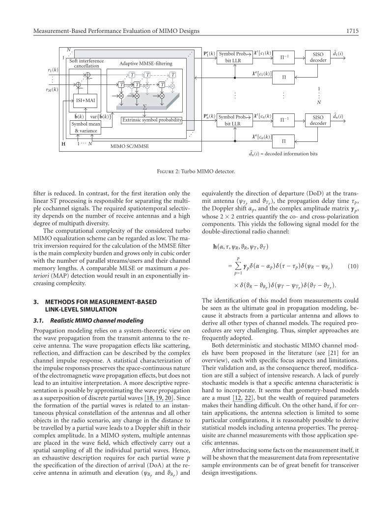
A simplified diagram of the turbo MIMO equalizer high-lighting the combined soft interference cancellation (SC) andminimum mean square error filtering (MMSE) is shown inFigure 2. Both steps rely on computing the mean and thevariance of each transmitted symbol on the basis of the mod-ulation symbol alphabet and the bit a priori log-likelihoodratios (LLRs) λa[cn(k)]. These values can be obtained by soft-input soft-output (SISO) decoding of the received coded bitscn(k) [16]. The estimated mean bn(k) of the coded transmitdata symbols is effectively a soft replica of the transmit sym-bols, which allows the soft cancellation of the ISI and MAIcomponents in the received signal vector. This is to be per-formed for each substream n,
rn(k) = r(k)−Hbn(k). (8)
The vector bn(k) comprises all soft symbol replicas, except
for the symbol of interest bn(k), which is set to zero. After theSC step, remaining ISI and MAI components are minimizedby applying an instantaneous MMSE filter wn(k) to the out-put of each of the N cancellers, zn(k) = wH
n (k)rn(k) [9, 11].This is especially important for the first iteration, where thecancellation process is without effect due to the unavailabilityof a priori information. The solution to the MMSE optimiza-tion is derived in [9, 11], resulting in
wn(k) = [H∆n(k)HH + σ2v I]−1
hn. (9)
Here, I is the identity matrix of size (LM) and ∆n(k) is thecovariance matrix of the estimated transmit symbols. Sincestatistical independence of the data symbols is assumed, this
matrix is diagonal with entries var{bn(k)} [16]. The MSE atthe output of the MMSE filter can be reasonably approxi-mated by a Gaussian distribution. This is the key for a low-complexity approximation of the extrinsic symbol probabil-ity which is required for each possible symbol of the actualmodulation alphabet of size Ms. The results are arranged inthe vector Pe
n(k). Following the derivation in [16, 17], theld(Ms) LLRs of the detected code bits in λe[cn(k)] are esti-mated by jointly utilizing the vector of extrinsic symbol prob-abilities and the available a priori coded bit LLRs λa[cn(k)]resulting in an iterative demapping. The interleavers Π anddeinterleavers Π−1 are equivalent to the corresponding inter-leavers within the Tx processing.
Over multiple iterations, the reliability of the estimated
coded data symbols bn(k) increases. Hence, the SC step ismore and more perfect and the importance of the ST MMSE
Measurement-Based Performance Evaluation of MIMO Designs 1715
T T T
T T T
Soft interferencecancellation Adaptive MMSE-filtering
Symbol mean& variance
Extrinsic symbol probability
∑ISI+MAI
MIMO SC/MMSE
Symbol Prob.bit LLR
Π−1 SISOdecoder
Π
Π−1
Π
Symbol Prob.bit LLR
SISOdecoder
N
1
H 1 . . . N
b(k) var{b(k)}
r1(k)...
rM(k)
Pe1(k) λe[c1(k)
]
Pen(k) λe[cn(k)
]
λa[c1(k)
]
λa[cn(k)
]
d1(i)
dn(i)
dn(i) = decoded information bits
......
...
1
N
. ..
. ..
. ..
. ..
. ..
. ..
. ..
Figure 2: Turbo MIMO detector.
filter is reduced. In contrast, for the first iteration only thelinear ST processing is responsible for separating the multi-ple cochannel signals. The required spatiotemporal selectiv-ity depends on the number of receive antennas and a highdegree of multipath diversity.
The computational complexity of the considered turboMIMO equalization scheme can be regarded as low. The ma-trix inversion required for the calculation of the MMSE filteris the main complexity burden and grows only in cubic orderwith the number of parallel streams/users and their channelmemory lengths. A comparable MLSE or maximum a pos-teriori (MAP) detection would result in an exponentially in-creasing complexity.
3. METHODS FOR MEASUREMENT-BASEDLINK-LEVEL SIMULATION
3.1. Realistic MIMO channel modeling
Propagation modeling relies on a system-theoretic view onthe wave propagation from the transmit antenna to the re-ceive antenna. The wave propagation effects like scattering,reflection, and diffraction can be described by the complexchannel impulse response. A statistical characterization ofthe impulse responses preserves the space-continuous natureof the electromagnetic wave propagation effects, but does notlead to an intuitive interpretation. A more descriptive repre-sentation is possible by approximating the wave propagationas a superposition of discrete partial waves [18, 19, 20]. Sincethe formation of the partial waves is related to an instan-taneous physical constellation of the antennas and all otherobjects in the radio scenario, any change in the distance tobe travelled by a partial wave leads to a Doppler shift in theircomplex amplitude. In a MIMO system, multiple antennasare placed in the wave field, which effectively carry out aspatial sampling of all the individual partial waves. Hence,an exhaustive description requires for each partial wave pthe specification of the direction of arrival (DoA) at the re-ceive antenna in azimuth and elevation (ψRp and ϑRp) and
equivalently the direction of departure (DoD) at the trans-mit antenna (ψTp and ϑTp), the propagation delay time τp,the Doppler shift αp, and the complex amplitude matrix γp,whose 2 × 2 entries quantify the co- and cross-polarizationcomponents. This yields the following signal model for thedouble-directional radio channel:
h(α, τ,ψR, ϑR,ψT , ϑT
)
=P∑p=1
γpδ(α− αp
)δ(τ − τp
)δ(ψR − ψRp
)
× δ(ϑR − ϑRp)δ(ψT − ψTp)δ(ϑT − ϑTp).
(10)
The identification of this model from measurements couldbe seen as the ultimate goal in propagation modeling, be-cause it abstracts from a particular antenna and allows toderive all other types of channel models. The required pro-cedures are very challenging. Thus, simpler approaches arefrequently adopted.
Both deterministic and stochastic MIMO channel mod-els have been proposed in the literature (see [21] for anoverview), each with specific focus aspects and limitations.Their validation and, as the consequence thereof, modifica-tion are still a subject of intensive research. A lack of purelystochastic models is that a specific antenna characteristic ishard to incorporate. It seems that geometry-based modelsare a must [12, 22], but the wealth of required parametersmakes their handling difficult. On the other hand, if for cer-tain applications, the antenna selection is limited to someparticular configurations, it is reasonably possible to derivestatistical models including antenna properties. The prereq-uisite are channel measurements with those application spe-cific antennas.
After introducing some facts on the measurement itself, itwill be shown that the measurement data from representativesample environments can be of great benefit for transceiverdesign investigations.
1716 EURASIP Journal on Applied Signal Processing
3.2. MIMO channel measurement
A modern multidimensional channel sounder device like theRUSK MIMO [23] from MEDAV is capable to capture thechannel characteristics for all dimensions involved in (10)completely in a Nyquist sense. The measurement principle isdescribed in [2]. It relies on the transmission of a specializedperiodic multifrequency test signal. Frequency-domain cor-relation at the receiver is employed to estimate the complexchannel frequency response. Multiple antennas at the trans-mitter as well as the receiver side are managed by fast antennamultiplexing which is synchronized to the test signal period.A temporal sequence of MIMO snapshots of the channelthus yields a 4-dimensional data array D with dimensions(Nf ,N ,M,Nt), whereNf is the number of frequency sampleswithin the measurement bandwidth B and Nt is the numberof temporal samples collected during the observation time.In case of dual-polarized antennas, the numbers N and Minclude both polarization ports per antenna. For the extrac-tion of the multidimensional path parameters in (10) fromthe measured frequency responses, high-resolution parame-ter estimation algorithms have been developed and success-fully applied [24]. A mandatory prerequisite is the use ofcarefully designed measurement antennas.
The selection of suitable antennas is of specific impor-tance, because it depends on the objectives of the measure-ment and the intended usage of the data. It should be em-phasized that certain use cases can be mutually contradictory.For example, for investigations of space diversity processing,an antenna element spacing of multiples of the wavelengthλ is usually desired. On the other hand, space coherent pro-cessing and high-resolution parameter estimation of the datais only possible if the element spacing is smaller than λ/2. Theability for a 3-dimensional resolution of the DoDs and DoAsis only possible if the array has an aperture in the horizontalas well as the vertical space dimension.
Another antenna related issue is the field of view both forthe individual elements and the antenna array as a whole.Three possible combinations are relevant: in planar arraystructures (linear and rectangular arrays) the elements andthe array cover only a sector. Circular arrays are constructedto have a 360◦ field of view with either directional elements(patch arrays, multibeam antennas) or omnidirectional ele-ments (dipole arrays) [2].
A certain constellation of Tx and Rx antennas in a mea-surement campaign should always resemble one of the po-tential MIMO system setups introduced in Section 2.1. Thisimplies consequentially the usable array configurations: di-rectional arrays are typically mounted at the hypothetic BSposition and antenna elements and/or arrays with omni-directional coverage are utilized at the user terminal posi-tion. An element spacing in the order of several λ is usu-ally an option for a BS array only. The large antenna spac-ings relevant to a multiuser scenario are mostly attained bya Tx side synthetic aperture principle, that is, by a sequen-tial measurement of the individual user positions. Since boththe propagation analysis and the performance evaluation arebased on statistical averages, it is also important to collect
Rx array position Tx route
ST12
ST5
ST6
ST7
ST8
ET1
y x
User1
User2
ST4
ST3
ST2
ST9
ST10
ST11
Figure 3: Measurement setup for a multiuser MIMO system.
a sufficient number of MIMO snapshots in each local sur-rounding. This is usually implemented by preferably equidis-tant measurements along predefined routes and/or repeatedmeasurements in similar but yet distinct Tx/Rx constella-tions.
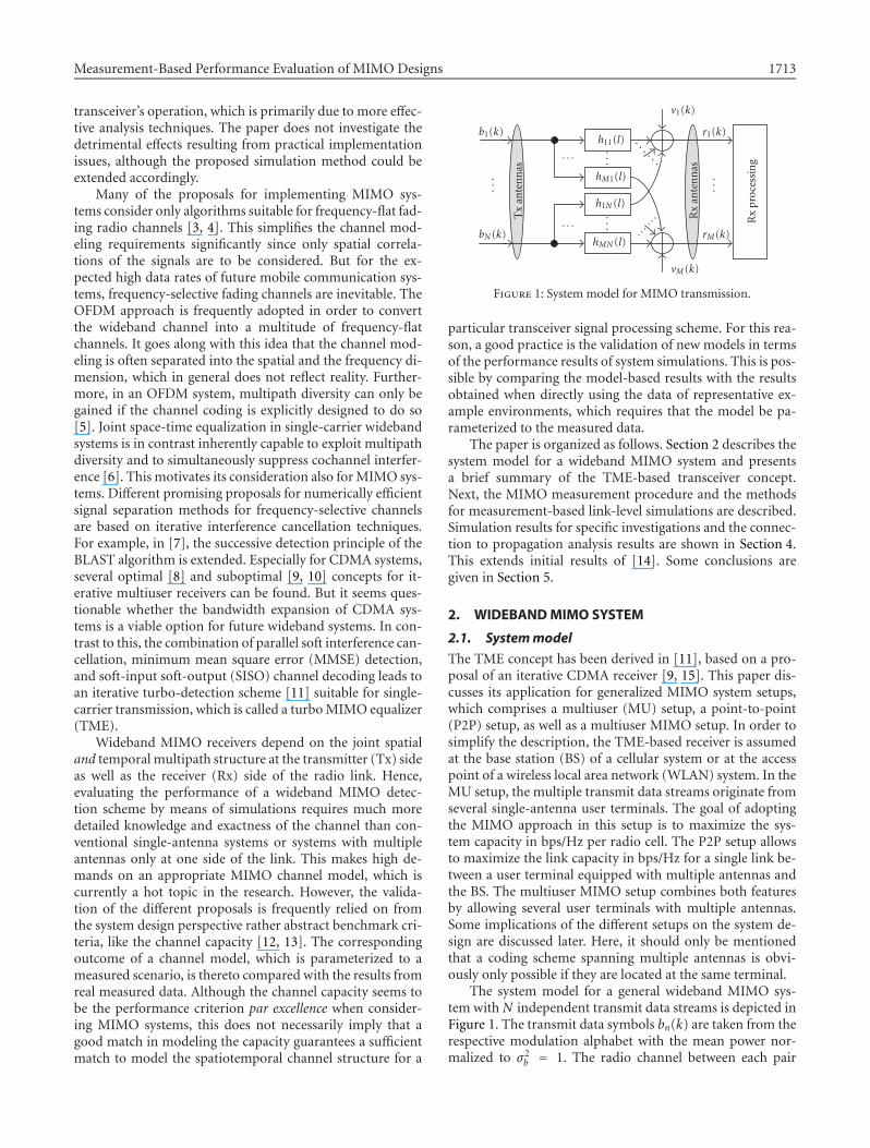
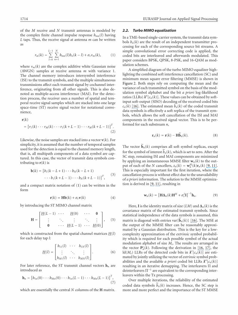
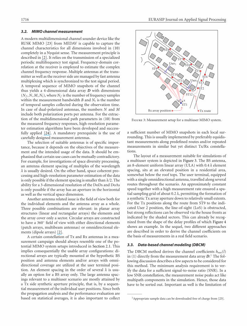
The layout of a measurement suitable for simulations ofa multiuser system is depicted in Figure 3. The BS antenna,an 8-element uniform linear array (ULA) with 0.4 λ elementspacing, sits at an elevated position in a residential area,somewhat below the roof tops. The user terminal, equippedwith a single omnidirectional antenna, travelled along severalroutes throughout the scenario. An approximately constantspeed together with a high measurement rate ensured a spa-tial sampling grid of about 0.2 λ, permitting the formation ofa synthetic Tx array aperture down to relatively small extents.For the Tx positions along the route from ST9 to the indi-cated User 2 position, the line-of-sight (LoS) is obstructed,but strong reflections can be observed via the house fronts asindicated by the shaded sectors. This can already be recog-nized from the shape of the delay profiles of which Figure 4shows an example. In the sequel, two different approachesare described in order to derive the channel coefficients onthe basis of measurements in a real field scenario.
3.3. Data-based channel modeling (DBCM)
The DBCM method derives the channel coefficients hmn(l)in (1) directly from the measurement data array D.1 The fol-lowing discussion describes a few aspects to be considered forthis method. The minimum analysis requirement is to ver-ify the data for a sufficient signal-to-noise ratio (SNR). In alow SNR constellation, the measurement noise peaks act likemultipath components in the simulation. Hence, those datahave to be sorted out. Important as well is the limitation of
1Appropriate sample data can be downloaded free of charge from [23].
Measurement-Based Performance Evaluation of MIMO Designs 1717
−60
−70
−80
−90
−100
−110
−120
Mag
nit
ude
(dB
)
0 200 400 600 800 1000 1200 1400 1600
Delay (ns)
Impulse response
Delay window (560 ns)
RMS delay spread (60 ns)
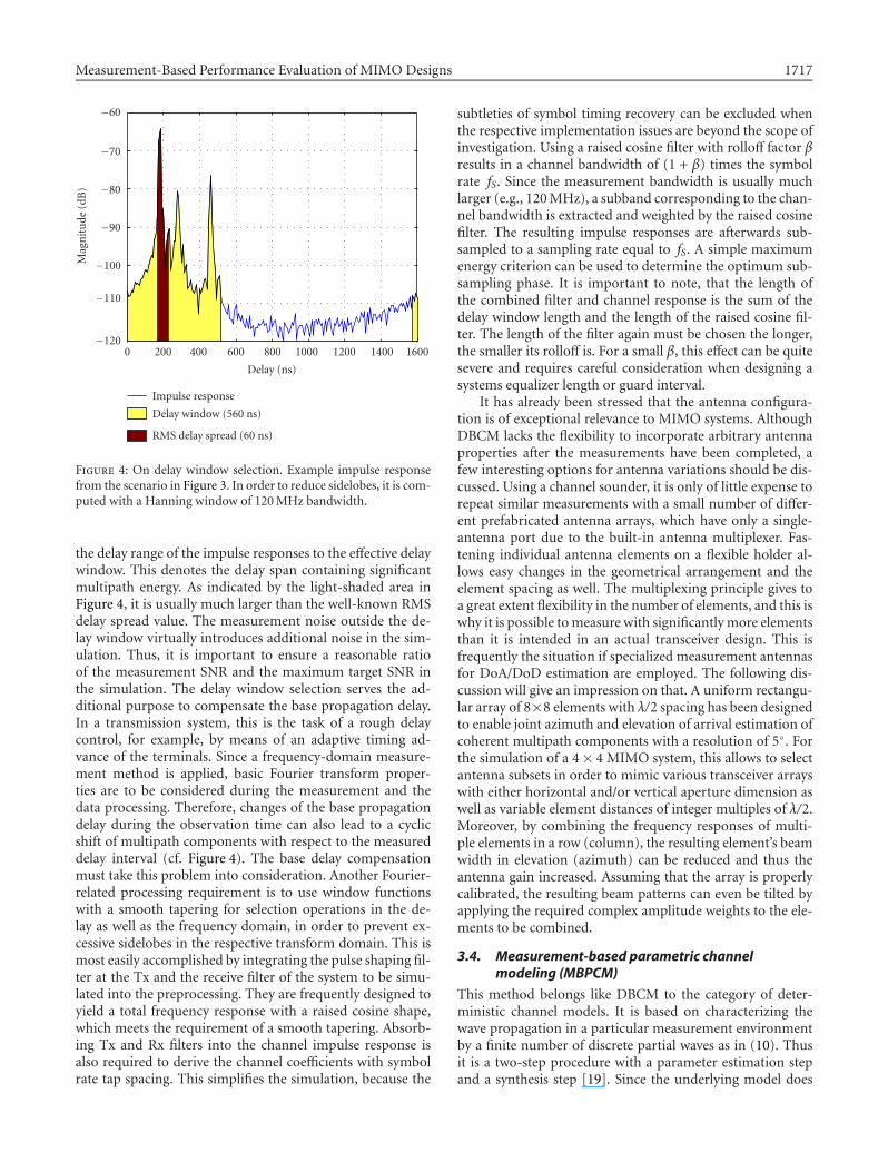
Figure 4: On delay window selection. Example impulse responsefrom the scenario in Figure 3. In order to reduce sidelobes, it is com-puted with a Hanning window of 120 MHz bandwidth.
the delay range of the impulse responses to the effective delaywindow. This denotes the delay span containing significantmultipath energy. As indicated by the light-shaded area inFigure 4, it is usually much larger than the well-known RMSdelay spread value. The measurement noise outside the de-lay window virtually introduces additional noise in the sim-ulation. Thus, it is important to ensure a reasonable ratioof the measurement SNR and the maximum target SNR inthe simulation. The delay window selection serves the ad-ditional purpose to compensate the base propagation delay.In a transmission system, this is the task of a rough delaycontrol, for example, by means of an adaptive timing ad-vance of the terminals. Since a frequency-domain measure-ment method is applied, basic Fourier transform proper-ties are to be considered during the measurement and thedata processing. Therefore, changes of the base propagationdelay during the observation time can also lead to a cyclicshift of multipath components with respect to the measureddelay interval (cf. Figure 4). The base delay compensationmust take this problem into consideration. Another Fourier-related processing requirement is to use window functionswith a smooth tapering for selection operations in the de-lay as well as the frequency domain, in order to prevent ex-cessive sidelobes in the respective transform domain. This ismost easily accomplished by integrating the pulse shaping fil-ter at the Tx and the receive filter of the system to be simu-lated into the preprocessing. They are frequently designed toyield a total frequency response with a raised cosine shape,which meets the requirement of a smooth tapering. Absorb-ing Tx and Rx filters into the channel impulse response isalso required to derive the channel coefficients with symbolrate tap spacing. This simplifies the simulation, because the
subtleties of symbol timing recovery can be excluded whenthe respective implementation issues are beyond the scope ofinvestigation. Using a raised cosine filter with rolloff factor βresults in a channel bandwidth of (1 + β) times the symbolrate fS. Since the measurement bandwidth is usually muchlarger (e.g., 120 MHz), a subband corresponding to the chan-nel bandwidth is extracted and weighted by the raised cosinefilter. The resulting impulse responses are afterwards sub-sampled to a sampling rate equal to fS. A simple maximumenergy criterion can be used to determine the optimum sub-sampling phase. It is important to note, that the length ofthe combined filter and channel response is the sum of thedelay window length and the length of the raised cosine fil-ter. The length of the filter again must be chosen the longer,the smaller its rolloff is. For a small β, this effect can be quitesevere and requires careful consideration when designing asystems equalizer length or guard interval.
It has already been stressed that the antenna configura-tion is of exceptional relevance to MIMO systems. AlthoughDBCM lacks the flexibility to incorporate arbitrary antennaproperties after the measurements have been completed, afew interesting options for antenna variations should be dis-cussed. Using a channel sounder, it is only of little expense torepeat similar measurements with a small number of differ-ent prefabricated antenna arrays, which have only a single-antenna port due to the built-in antenna multiplexer. Fas-tening individual antenna elements on a flexible holder al-lows easy changes in the geometrical arrangement and theelement spacing as well. The multiplexing principle gives toa great extent flexibility in the number of elements, and this iswhy it is possible to measure with significantly more elementsthan it is intended in an actual transceiver design. This isfrequently the situation if specialized measurement antennasfor DoA/DoD estimation are employed. The following dis-cussion will give an impression on that. A uniform rectangu-lar array of 8×8 elements with λ/2 spacing has been designedto enable joint azimuth and elevation of arrival estimation ofcoherent multipath components with a resolution of 5◦. Forthe simulation of a 4× 4 MIMO system, this allows to selectantenna subsets in order to mimic various transceiver arrayswith either horizontal and/or vertical aperture dimension aswell as variable element distances of integer multiples of λ/2.Moreover, by combining the frequency responses of multi-ple elements in a row (column), the resulting element’s beamwidth in elevation (azimuth) can be reduced and thus theantenna gain increased. Assuming that the array is properlycalibrated, the resulting beam patterns can even be tilted byapplying the required complex amplitude weights to the ele-ments to be combined.
3.4. Measurement-based parametric channelmodeling (MBPCM)
This method belongs like DBCM to the category of deter-ministic channel models. It is based on characterizing thewave propagation in a particular measurement environmentby a finite number of discrete partial waves as in (10). Thusit is a two-step procedure with a parameter estimation stepand a synthesis step [19]. Since the underlying model does
1718 EURASIP Journal on Applied Signal Processing
150
100
50
0
−50
−100
Rx
azim
uth
(deg
)
0 3 6 9 12
Position (m)
0
−2
−4
−6
−8
−10
Mag
nit
ude
nor
mal
ized
(dB
)
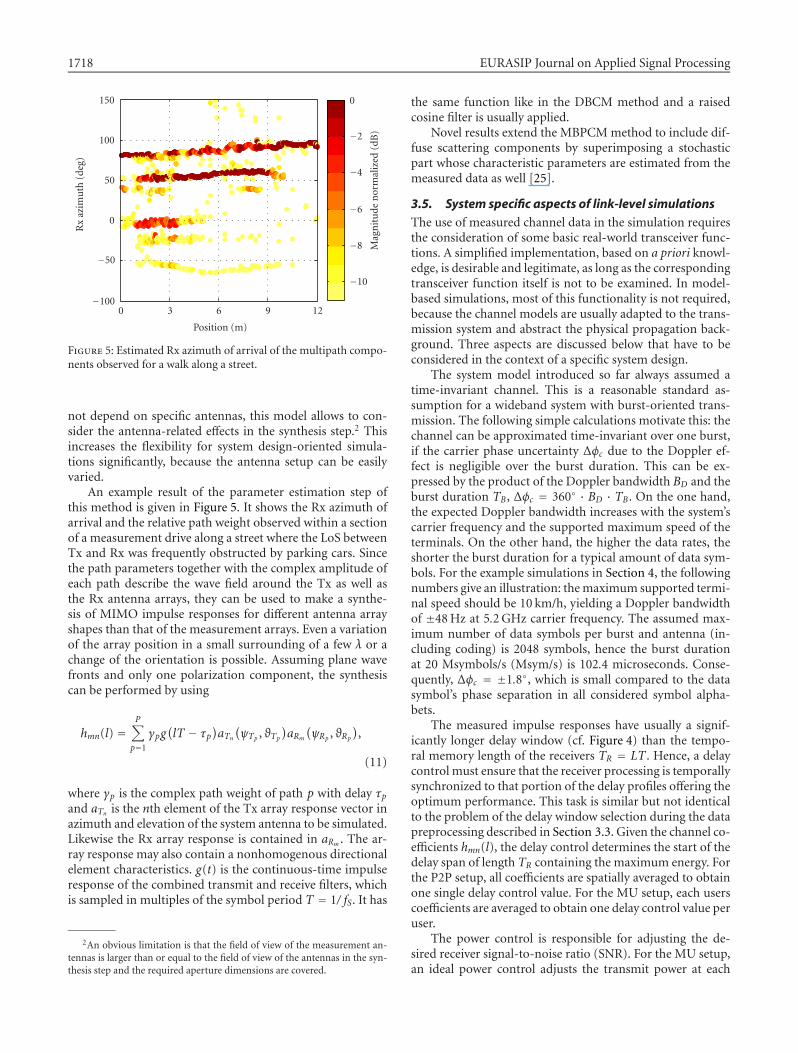
Figure 5: Estimated Rx azimuth of arrival of the multipath compo-nents observed for a walk along a street.
not depend on specific antennas, this model allows to con-sider the antenna-related effects in the synthesis step.2 Thisincreases the flexibility for system design-oriented simula-tions significantly, because the antenna setup can be easilyvaried.
An example result of the parameter estimation step ofthis method is given in Figure 5. It shows the Rx azimuth ofarrival and the relative path weight observed within a sectionof a measurement drive along a street where the LoS betweenTx and Rx was frequently obstructed by parking cars. Sincethe path parameters together with the complex amplitude ofeach path describe the wave field around the Tx as well asthe Rx antenna arrays, they can be used to make a synthe-sis of MIMO impulse responses for different antenna arrayshapes than that of the measurement arrays. Even a variationof the array position in a small surrounding of a few λ or achange of the orientation is possible. Assuming plane wavefronts and only one polarization component, the synthesiscan be performed by using
hmn(l) =P∑p=1
γpg(lT − τp
)aTn(ψTp , ϑTp
)aRm(ψRp , ϑRp
),
(11)
where γp is the complex path weight of path p with delay τpand aTn is the nth element of the Tx array response vector inazimuth and elevation of the system antenna to be simulated.Likewise the Rx array response is contained in aRm . The ar-ray response may also contain a nonhomogenous directionalelement characteristics. g(t) is the continuous-time impulseresponse of the combined transmit and receive filters, whichis sampled in multiples of the symbol period T = 1/ fS. It has
2An obvious limitation is that the field of view of the measurement an-tennas is larger than or equal to the field of view of the antennas in the syn-thesis step and the required aperture dimensions are covered.
the same function like in the DBCM method and a raisedcosine filter is usually applied.
Novel results extend the MBPCM method to include dif-fuse scattering components by superimposing a stochasticpart whose characteristic parameters are estimated from themeasured data as well [25].
3.5. System specific aspects of link-level simulations
The use of measured channel data in the simulation requiresthe consideration of some basic real-world transceiver func-tions. A simplified implementation, based on a priori knowl-edge, is desirable and legitimate, as long as the correspondingtransceiver function itself is not to be examined. In model-based simulations, most of this functionality is not required,because the channel models are usually adapted to the trans-mission system and abstract the physical propagation back-ground. Three aspects are discussed below that have to beconsidered in the context of a specific system design.
The system model introduced so far always assumed atime-invariant channel. This is a reasonable standard as-sumption for a wideband system with burst-oriented trans-mission. The following simple calculations motivate this: thechannel can be approximated time-invariant over one burst,if the carrier phase uncertainty ∆φc due to the Doppler ef-fect is negligible over the burst duration. This can be ex-pressed by the product of the Doppler bandwidth BD and theburst duration TB, ∆φc = 360◦ · BD · TB. On the one hand,the expected Doppler bandwidth increases with the system’scarrier frequency and the supported maximum speed of theterminals. On the other hand, the higher the data rates, theshorter the burst duration for a typical amount of data sym-bols. For the example simulations in Section 4, the followingnumbers give an illustration: the maximum supported termi-nal speed should be 10 km/h, yielding a Doppler bandwidthof ±48 Hz at 5.2 GHz carrier frequency. The assumed max-imum number of data symbols per burst and antenna (in-cluding coding) is 2048 symbols, hence the burst durationat 20 Msymbols/s (Msym/s) is 102.4 microseconds. Conse-quently, ∆φc = ±1.8◦, which is small compared to the datasymbol’s phase separation in all considered symbol alpha-bets.
The measured impulse responses have usually a signif-icantly longer delay window (cf. Figure 4) than the tempo-ral memory length of the receivers TR = LT . Hence, a delaycontrol must ensure that the receiver processing is temporallysynchronized to that portion of the delay profiles offering theoptimum performance. This task is similar but not identicalto the problem of the delay window selection during the datapreprocessing described in Section 3.3. Given the channel co-efficients hmn(l), the delay control determines the start of thedelay span of length TR containing the maximum energy. Forthe P2P setup, all coefficients are spatially averaged to obtainone single delay control value. For the MU setup, each userscoefficients are averaged to obtain one delay control value peruser.
The power control is responsible for adjusting the de-sired receiver signal-to-noise ratio (SNR). For the MU setup,an ideal power control adjusts the transmit power at each

Measurement-Based Performance Evaluation of MIMO Designs 1719
transmit antenna such that the mean received power over allelements is identical for all users,
∑Mm=1 Pmn = M/N . While
this holds constant the total transmit power independentlyof the number of users, the total received power increaseswith the number of receive antennas. This is a pragmatic rule,which keeps the spirit behind the MIMO theory to increasethe channel capacity by adding parallel channels at constanttransmit power, while retaining the physical fact that the to-tal received power increases with the number of antennaslocated in an electromagnetic field of a given strength. Forthe P2P setup, a modified power control scheme with lowercomplexity seems attractive, which adjusts the total receivedmean power while transmitting identical powers by each an-tenna,
∑Mm=1
∑Nn=1 Pmn = M. But it has been found that this
scheme introduces partially a serious performance degrada-tion of the TME-based system.
4. SIMULATIONS FOR REAL FIELD SCENARIOS
This section covers by means of examples the strategies toevaluate the bit error rate (BER) performance of systemsbased on the TME concept as introduced in Section 2.2.The focus lies on characterizing the robustness w.r.t. vary-ing propagation conditions and the influence of several de-sign options. All simulations are based on measured chan-nel data at 5.2 GHz carrier frequency. The assumed symbolrates are 12 Msym/s (β = 0.5) in case of the MU scenariosand 20 Msym/s (β = 0.25) for the P2P scenarios. Each datastream of the TME system is convolutionally encoded (coderate 1/2, constraint length 3, G = [7, 5]) and random inter-leaved. Gray mapping is used to derive the symbol constel-lations of the higher modulation schemes. On the receiverside, the channel decoding part was performed by the max-log-map algorithm [26].
4.1. Result evaluation basics
The outcome of link-level simulations are usually mean BERsaveraged over a certain number of statistical realizations ofthe radio channel. In measurement-based simulations, thoserealizations are essentially obtained by changing the antennapositions in the scenario. Meaningful average BER results canonly be expected if the averaging is carried out over channelrealizations with similar statistics. For single antenna systemsthe assertion of statistical stationarity of the channel is rela-tively simple, because only the delay- (or frequency-) domainstatistics needs to be observed. For MIMO systems, this taskis much harder, since the spatiotemporal structure amongthe multiple transmit channels needs to be considered. Theparametric channel estimation as already introduced aboveis very valuable, since it enables a matching between the in-stantaneous physical propagation conditions and the perfor-mance of a certain receiver configuration. The example inFigure 5 shows that even within only a few meters the prop-agation conditions can change dramatically, with just as dra-matic implications on the receiver performance. The secondsimulation example in Section 4.2 and the examples in Sec-tions 4.3 and 4.4 illustrate the effect of selective failures for
certain Tx-Rx constellations. Here, the BER is high even athigh SNR, or it is significantly higher than in very similarconstellations. Selective failures are typically not producedin channel model-based simulations. A reasonable strategyto deal with this effect is needed in order to maintain valu-able average performance conclusions. The strategy dependson the desired utilization of the simulation results. The ex-clusion of a certain percentage of worst case constellationsmight be an option.
On the other hand, those selective failures give a strongmotivation for investigating link adaptation schemes and cri-teria for an operational system. Link adaptation schemesfor MIMO system have to consider options that go beyondthe traditional adaptive modulation and coding selection.This may comprise the adjustment of the number of paralleltransmit signals, incremental coding, or the selection of an-tenna subsets according to a specific propagation situation.
4.2. Variable antenna configurations
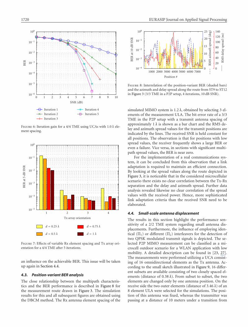
The first example illustrates the basic performance behav-ior of the iterative MIMO transceiver scheme in a P2P sce-nario. The MBPCM method has been used to synthesize theMIMO channel coefficients based on the multipath param-eters estimated from measured data. The parameters havebeen inspected to select a short section of the route displayedin Figure 5 with a stationary multipath situation (positionsfrom 1 m to 3 m) and a particularly high delay spread (75nanoseconds). Figure 6 shows the average BER over 15 chan-nel snapshots of the selected section. The simulations havebeen carried out with 4 simultaneous BPSK transmit sig-nals and 4 receive antennas (4/4 MIMO system). Uniformcircular arrays (UCA) at both the receiver and the transmit-ter with omnidirectional antenna elements and 1.0 λ spacinghave been assumed. The receiver uses L = 7 delay taps perantenna element. An impressive gain can be obtained by per-forming multiple iterations of the receiver processing.
The second example extends the previous one by investi-gating the robustness of the 4/4 MIMO system with respectto a variable Rx antenna element spacing as well as the geo-metrical orientation of the Tx array. This combination is mo-tivated by observing that the Rx azimuth spread in the con-sidered section is with about 30◦ significantly smaller thanthe Tx azimuth spread of about 50◦. A fixed element spac-ing of the Tx UCA of 1.0 λ has been assumed, the Tx ori-entation is changed by rotating the array in steps of 22.5◦
(i.e., orientation 5 is identical to orientation 1), and the Rxelement spacing is varied between 0.25 λ and 1.0 λ. Figure 7shows the BER for each constellation at an SNR of 5 dB. Thefirst Tx array orientation yields a significantly higher BERthan all others and shows a clear advantage for higher Rx el-ement spacings. Turning the Tx array reveals the existenceof an optimum around orientation 3 with a U-shaped in-crease on either side. This indicates that the effective num-ber of multipath components in this scenario is too small toensure the separability of the 4 transmit signals for every an-tenna constellation. Hence, the specific superposition of themultipath components at the different antenna positions has
1720 EURASIP Journal on Applied Signal Processing
100
10−1
10−2
10−3
10−4
10−5
10−6
BE
R
0 1 2 3 4 5 6 7 8 9 10
SNR (dB)
Iteration 1
Iteration 2
Iteration 3
Iteration 4
Iteration 5
Figure 6: Iteration gain for a 4/4 TME using UCAs with 1.0 λ ele-ment spacing.
100
10−1
10−2
10−3
10−4
10−5
BE
Rat
5dB
SNR
1 2 3 4
Tx array orientation
d = 0.25 λ
d = 0.5 λ
d = 0.75 λ
d = 1 λ
Figure 7: Effects of variable Rx element spacing and Tx array ori-entation for a 4/4 TME after 5 iterations.
an influence on the achievable BER. This issue will be takenup again in Section 4.4.
4.3. Position-variant BER analysis
The close relationship between the multipath characteris-tics and the BER performance is described in Figure 8 forthe measurement route drawn in Figure 3. The simulationresults for this and all subsequent figures are obtained usingthe DBCM method. The Rx antenna element spacing of the
100
10−1
10−2
10−3
10−4
BE
Rat
10dB
SNR
1000 2000 3000 4000 5000 6000 7000
Position #
25
20
15
10
5
0
RM
Saz
imu
thsp
read
(deg
) 140
120
100
80
60
40
20
0
RM
Sde
lay
spre
ad(n
s)
Figure 8: Interrelation of the position-variant BER (shaded bars)and the azimuth and delay spread along the route from ST9 to ST12in Figure 3 (3/3 TME in a P2P setup, 4 iterations, 10 dB SNR).
simulated MIMO system is 1.2 λ, obtained by selecting 3 el-ements of the measurement ULA. The bit error rate of a 3/3TME in the P2P setup with a transmit antenna spacing ofapproximately 1 λ is shown as a bar chart and the RMS de-lay and azimuth spread values for the transmit positions areindicated by the lines. The received SNR is held constant forall positions. The observation is that for positions with lowspread values, the receiver frequently shows a large BER oreven a failure. Vice versa, in sections with significant multi-path spread values, the BER is near zero.
For the implementation of a real communications sys-tem, it can be concluded from this observation that a linkadaptation is required to maintain an efficient connection.By looking at the spread values along the route depicted inFigure 3, it is noticeable that in the considered microcellularscenario there exists no clear correlation between the Tx-Rxseparation and the delay and azimuth spread. Further dataanalysis revealed likewise no clear correlation of the spreadvalues with the received power. Hence, more sophisticatedlink adaptation criteria than the received SNR need to beelaborated.
4.4. Small-scale antenna displacement
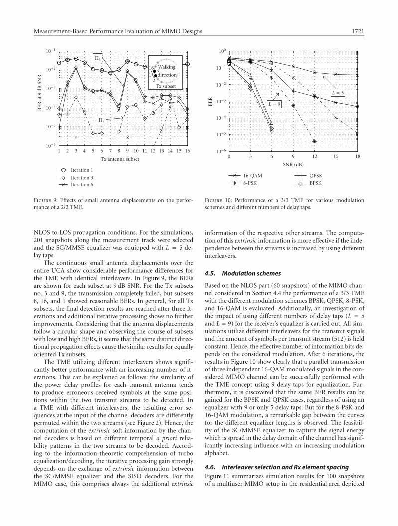
The results in this section highlight the performance sen-sitivity of a 2/2 TME system regarding small antenna dis-placements. Furthermore, the influence of employing iden-tical (Π1) or different (Π2) interleavers for the detection oftwo QPSK modulated transmit signals is depicted. The se-lected P2P MIMO measurement can be classified as a mi-crocell outdoor scenario for a WLAN application with lowmobility. A detailed description can be found in [23, 27].The measurements were performed utilizing a UCA consist-ing of 16 omnidirectional elements as the Tx antenna. Ac-cording to the small sketch illustrated in Figure 9, 16 differ-ent subsets are available consisting of two closely spaced el-ements (distance of 0.38 λ). From subset to subset, the twoelements are changed only by one antenna position. On thereceive side the two outer elements (distance of 3.46 λ) of an8 element ULA were selected for the simulations. The posi-tion of this antenna was fixed, whereas the transmitter waspassing at a distance of 10 meters under a transition from
Measurement-Based Performance Evaluation of MIMO Designs 1721
10−1
10−2
10−3
10−4
10−5
10−6
BE
Rat
9dB
SNR
1 2 3 4 5 6 7 8 9 10 11 12 13 14 15 16
Tx antenna subset
Iteration 1
Iteration 3Iteration 6
Π1
Π2
Walking
direction161
2Tx subset
Figure 9: Effects of small antenna displacements on the perfor-mance of a 2/2 TME.
NLOS to LOS propagation conditions. For the simulations,201 snapshots along the measurement track were selectedand the SC/MMSE equalizer was equipped with L = 5 de-lay taps.
The continuous small antenna displacements over theentire UCA show considerable performance differences forthe TME with identical interleavers. In Figure 9, the BERsare shown for each subset at 9 dB SNR. For the Tx subsetsno. 3 and 9, the transmission completely failed, but subsets8, 16, and 1 showed reasonable BERs. In general, for all Txsubsets, the final detection results are reached after three it-erations and additional iterative processing shows no furtherimprovements. Considering that the antenna displacementsfollow a circular shape and observing the course of subsetswith low and high BERs, it seems that the same distinct direc-tional propagation effects cause the similar results for equallyoriented Tx subsets.
The TME utilizing different interleavers shows signifi-cantly better performance with an increasing number of it-erations. This can be explained as follows: the similarity ofthe power delay profiles for each transmit antenna tendsto produce erroneous received symbols at the same posi-tions within the two transmit streams to be detected. Ina TME with different interleavers, the resulting error se-quences at the input of the channel decoders are differentlypermuted within the two streams (see Figure 2). Hence, thecomputation of the extrinsic soft information by the chan-nel decoders is based on different temporal a priori relia-bility patterns in the two streams to be decoded. Accord-ing to the information-theoretic comprehension of turboequalization/decoding, the iterative processing gain stronglydepends on the exchange of extrinsic information betweenthe SC/MMSE equalizer and the SISO decoders. For theMIMO case, this comprises always the additional extrinsic
100
10−1
10−2
10−3
10−4
10−5
10−6
BE
R
0 3 6 9 12 15 18
SNR (dB)
16-QAM
8-PSK
QPSK
BPSK
L = 9
L = 5
Figure 10: Performance of a 3/3 TME for various modulationschemes and different numbers of delay taps.
information of the respective other streams. The computa-tion of this extrinsic information is more effective if the inde-pendence between the streams is increased by using differentinterleavers.
4.5. Modulation schemes
Based on the NLOS part (60 snapshots) of the MIMO chan-nel considered in Section 4.4 the performance of a 3/3 TMEwith the different modulation schemes BPSK, QPSK, 8-PSK,and 16-QAM is evaluated. Additionally, an investigation ofthe impact of using different numbers of delay taps (L = 5and L = 9) for the receiver’s equalizer is carried out. All sim-ulations utilize different interleavers for the transmit signalsand the amount of symbols per transmit stream (512) is heldconstant. Hence, the effective number of information bits de-pends on the considered modulation. After 6 iterations, theresults in Figure 10 show clearly that a parallel transmissionof three independent 16-QAM modulated signals in the con-sidered MIMO channel can be successfully performed withthe TME concept using 9 delay taps for equalization. Fur-thermore, it is discovered that the same BER results can begained for the BPSK and QPSK cases, regardless of using anequalizer with 9 or only 5 delay taps. But for the 8-PSK and16-QAM modulation, a remarkable gap between the curvesfor the different equalizer lengths is observed. The feasibil-ity of the SC/MMSE equalizer to capture the signal energywhich is spread in the delay domain of the channel has signif-icantly increasing influence with an increasing modulationalphabet.
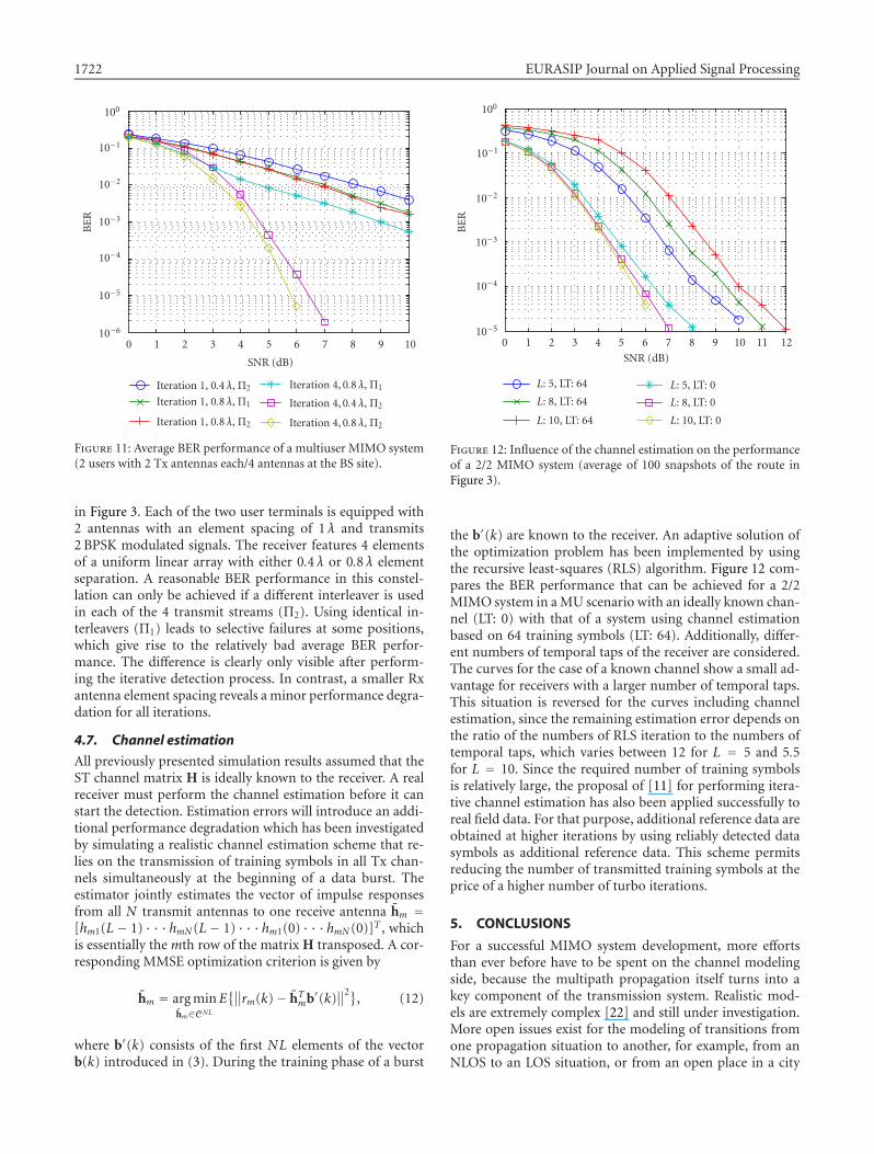
4.6. Interleaver selection and Rx element spacingFigure 11 summarizes simulation results for 100 snapshotsof a multiuser MIMO setup in the residential area depicted
1722 EURASIP Journal on Applied Signal Processing
100
10−1
10−2
10−3
10−4
10−5
10−6
BE
R
0 1 2 3 4 5 6 7 8 9 10
SNR (dB)
Iteration 1, 0.4 λ, Π2
Iteration 1, 0.8 λ, Π1
Iteration 1, 0.8 λ, Π2
Iteration 4, 0.8 λ, Π1
Iteration 4, 0.4 λ, Π2
Iteration 4, 0.8 λ, Π2
Figure 11: Average BER performance of a multiuser MIMO system(2 users with 2 Tx antennas each/4 antennas at the BS site).
in Figure 3. Each of the two user terminals is equipped with2 antennas with an element spacing of 1 λ and transmits2 BPSK modulated signals. The receiver features 4 elementsof a uniform linear array with either 0.4 λ or 0.8 λ elementseparation. A reasonable BER performance in this constel-lation can only be achieved if a different interleaver is usedin each of the 4 transmit streams (Π2). Using identical in-terleavers (Π1) leads to selective failures at some positions,which give rise to the relatively bad average BER perfor-mance. The difference is clearly only visible after perform-ing the iterative detection process. In contrast, a smaller Rxantenna element spacing reveals a minor performance degra-dation for all iterations.
4.7. Channel estimation
All previously presented simulation results assumed that theST channel matrix H is ideally known to the receiver. A realreceiver must perform the channel estimation before it canstart the detection. Estimation errors will introduce an addi-tional performance degradation which has been investigatedby simulating a realistic channel estimation scheme that re-lies on the transmission of training symbols in all Tx chan-nels simultaneously at the beginning of a data burst. Theestimator jointly estimates the vector of impulse responsesfrom all N transmit antennas to one receive antenna hm =[hm1(L − 1) · · ·hmN (L − 1) · · ·hm1(0) · · ·hmN (0)]T , whichis essentially the mth row of the matrix H transposed. A cor-responding MMSE optimization criterion is given by
hm = arg minhm∈CNL
E{∥∥rm(k)− hTmb′(k)
∥∥2}, (12)
where b′(k) consists of the first NL elements of the vectorb(k) introduced in (3). During the training phase of a burst
100
10−1
10−2
10−3
10−4
10−5
BE
R
0 1 2 3 4 5 6 7 8 9 10 11 12
SNR (dB)
L: 5, LT: 64
L: 8, LT: 64
L: 10, LT: 64
L: 5, LT: 0
L: 8, LT: 0
L: 10, LT: 0
Figure 12: Influence of the channel estimation on the performanceof a 2/2 MIMO system (average of 100 snapshots of the route inFigure 3).
the b′(k) are known to the receiver. An adaptive solution ofthe optimization problem has been implemented by usingthe recursive least-squares (RLS) algorithm. Figure 12 com-pares the BER performance that can be achieved for a 2/2MIMO system in a MU scenario with an ideally known chan-nel (LT: 0) with that of a system using channel estimationbased on 64 training symbols (LT: 64). Additionally, differ-ent numbers of temporal taps of the receiver are considered.The curves for the case of a known channel show a small ad-vantage for receivers with a larger number of temporal taps.This situation is reversed for the curves including channelestimation, since the remaining estimation error depends onthe ratio of the numbers of RLS iteration to the numbers oftemporal taps, which varies between 12 for L = 5 and 5.5for L = 10. Since the required number of training symbolsis relatively large, the proposal of [11] for performing itera-tive channel estimation has also been applied successfully toreal field data. For that purpose, additional reference data areobtained at higher iterations by using reliably detected datasymbols as additional reference data. This scheme permitsreducing the number of transmitted training symbols at theprice of a higher number of turbo iterations.
5. CONCLUSIONS
For a successful MIMO system development, more effortsthan ever before have to be spent on the channel modelingside, because the multipath propagation itself turns into akey component of the transmission system. Realistic mod-els are extremely complex [22] and still under investigation.More open issues exist for the modeling of transitions fromone propagation situation to another, for example, from anNLOS to an LOS situation, or from an open place in a city
Measurement-Based Performance Evaluation of MIMO Designs 1723
into a narrow street. Consequently, new transceiver conceptsshould always also be verified by using channel measure-ments in the appropriate system deployment scenarios suchas high-speed public access scenarios (e.g., access point tocar), public open indoor areas (e.g., airport), or factory halls.The acquired data can afterwards be used in offline simu-lations for comparing even completely different transceiverarchitectures with exact reproducibility.
Developing the new wireless networks beyond 3G mayrequire the consideration of completely new transceiver con-stellations, for example, multihop systems, distributed multi-antenna systems, and tandem air interfaces. The presentedperformance evaluation methodology can be extended to en-able reliable propagation modeling also for such configura-tions. Furthermore, the consideration of network aspects bymeasurement-based system-level simulations is possible if si-multaneous measurements from multiple sites in a certainradio environment are carried out.
Two different methods for measurement-based MIMOchannel modeling have been presented and compared. Theirapplication to the performance evaluation of the turbo-MIMO equalizer concept revealed a reasonable performancein many real field scenarios, but also a sensitivity to the prop-agation conditions. The observed results suggest that ad-vanced link adaptation algorithms are required to preventexcessive BERs. The causality of certain performance effectscan be traced back to the instantaneous channel conditionsby referring to the results of a propagation analysis, eitherby high-resolution estimation of multipath parameters or bynonparametric statistical investigations. This provides signif-icant insights both for the verification and enhancement ofchannel models and for the optimization of particular Txand Rx signal processing schemes. Moreover, the describedmethods provide exceptional opportunities for investigatingadequate link adaptation criteria and strategies.
According to the opinion of the authors, realistic channelmodeling in MIMO systems is presently only possible witha balanced mix of a deterministic modeling approach forrepresentative scenarios and the frequently favored stochas-tic modeling approaches. Only this allows to identify therelevant factors influencing the transceiver performance. Inthis context, a real-time MIMO channel sounder is a valu-able component of a rapid prototyping system when devel-oping new physical layer principles. A complete frameworkfor measurement-based simulations comprises besides themeasurement equipment a tool chain for measurement dataarchiving, data handling, and propagation analysis. The hugepotential of measurement-based methods for fast and reli-able performance evaluation has not yet been fully recog-nized in industry but the acceptance is growing.
ACKNOWLEDGMENTS
The authors appreciate the support of the colleagues at Ilme-nau University of Technology for performing the measure-ments and the propagation data analysis. Special thanks go toTad Matsumoto, Oulu University, for initiating this researchand for continued cooperation.
REFERENCES
[1] G. J. Foschini and M. J. Gans, “On limits of wireless personalcommunications in a fading environment when using multi-ple antennas,” Wireless Personal Communications, vol. 6, no. 3,pp. 311–335, 1998.
[2] R. S. Thoma, D. Hampicke, A. Richter, G. Sommerkorn, andU. Trautwein, “MIMO vector channel sounder measurementfor smart antenna system evaluation,” European Transactionson Telecommunications, vol. 12, no. 5, pp. 427–438, 2001.
[3] D. Gesbert, M. Shafi, D. Shiu, P. J. Smith, and A. Naguib,“From theory to practice: an overview of MIMO space-time coded wireless systems,” IEEE J. Select. Areas Commun.,vol. 21, no. 3, pp. 281–302, 2003.
[4] B. M. Hochwald and S. ten Brink, “Achieving near-capacity ona multiple-antenna channel,” IEEE Trans. Commun., vol. 51,no. 3, pp. 389–399, 2003.
[5] G. Raleigh and J. M. Cioffi, “Spatio-temporal coding for wire-less communication,” IEEE Trans. Commun., vol. 46, no. 3,pp. 357–366, 1998.
[6] A. J. Paulraj and C. B. Papadias, “Space-time processingfor wireless communications,” IEEE Signal Processing Mag.,vol. 14, no. 6, pp. 49–83, 1997.
[7] S. Lek, “Turbo space-time processing to improve wirelesschannel capacity,” IEEE Trans. Commun., vol. 48, no. 8,pp. 1347–1359, 2000.
[8] M. Moher, “An iterative multiuser decoder for near-capacitycommunications,” IEEE Trans. Commun., vol. 46, no. 7,pp. 870–880, 1998.
[9] X. Wang and H. V. Poor, “Iterative (turbo) soft interferencecancellation and decoding for coded CDMA,” IEEE Trans.Commun., vol. 47, no. 7, pp. 1046–1061, 1999.
[10] M. C. Reed, C. B. Schlegel, P. D. Alexander, and J. A. Asen-storfer, “Iterative multiuser detection for CDMA with FEC:near-single-user performance,” IEEE Trans. Commun., vol. 46,no. 12, pp. 1693–1699, 1998.
[11] T. Abe and T. Matsumoto, “Space-time turbo equalization infrequency-selective MIMO channels,” IEEE Trans. Veh. Tech-nol., vol. 52, no. 3, pp. 469–475, 2003.
[12] D. Gesbert, H. Bolcskei, D. A. Gore, and A. J. Paulraj, “Out-door MIMO wireless channels: models and performance pre-diction,” IEEE Trans. Commun., vol. 50, no. 12, pp. 1926–1934, 2002.
[13] H. Ozcelik, M. Herdin, W. Weichselberger, J. Wallace, andE. Bonek, “Deficiencies of ‘Kronecker’ MIMO radio chan-nel model,” Electronics Letters, vol. 39, no. 16, pp. 1209–1210,2003.
[14] U. Trautwein, T. Matsumoto, C. Schneider, and R. S. Thoma,“Exploring the performance of turbo MIMO equalization inreal field scenarios,” in Proc. 5th International Symposium onWireless Personal Multimedia Communications (WPMC ’02),vol. 2, pp. 422–426, Honolulu, Hawaii, USA, October 2002.
[15] D. Reynolds and X. Wang, “Low complexity turbo-equalization for diversity channels,” Signal Processing, vol. 81,no. 5, pp. 989–995, 2001.
[16] A. Dejonghe and L. Vandendorpe, “Turbo equalization formultilevel modulation: a low complexity approach,” in Proc.IEEE International Conference on Communications (ICC ’02),vol. 3, pp. 1863–1867, New York, NY, USA, April–May 2002.
[17] S. ten Brink, J. Speidel, and R.-H. Yan, “Iterative demappingand decoding for multilevel modulation,” in Proc. IEEE GlobalTelecommunications Conference (GLOBECOM ’98), vol. 1, pp.579–584, Sydney, NSW, Australia, November 1998.
[18] M. Steinbauer, A. F. Molisch, and E. Bonek, “The double-directional radio channel,” IEEE Antennas Propagat. Mag.,vol. 43, no. 4, pp. 51–63, 2001.
1724 EURASIP Journal on Applied Signal Processing
[19] R. S. Thoma, D. Hampicke, M. Landmann, A. Richter,and S. Sommerkorn, “Measurement-based parametric chan-nel modelling (MBPCM),” in Proc. International Conferenceon Electromagnetics in Advanced Applications (ICEAA ’03),Torino, Italy, September 2003.
[20] H. Xu, D. Chizhik, H. Huang, and R. Valenzuela, “A wave-based wideband MIMO channel modeling technique,” inProc. 13th IEEE International Symposium on Personal, Indoor,and Mobile Radio Communications (PIMRC ’02), vol. 4, pp.1626–1630, Lisbon, Portugal, September 2002.
[21] K. Yu and B. Ottersten, “Models for MIMO propagation chan-nels: a review,” Wireless Communications and Mobile Comput-ing, vol. 2, no. 7, pp. 653–666, 2002, Special Issue on “AdaptiveAntennas and MIMO Systems”.
[22] A. F. Molisch, “A generic model for MIMO wireless propaga-tion channels in macro- and microcells,” IEEE Trans. SignalProcessing, vol. 52, no. 1, pp. 61–71, 2004.
[23] http://www.channelsounder.de.[24] R. S. Thoma, M. Landmann, and A. Richter, “RIMAX—A
maximum likelihood framework for parameter estimation inmultidimensional channel sounding,” in Proc. InternationalSymposium on Antennas and Propagation (ISAP ’04), pp. 53–56, Sendai, Japan, August 2004.
[25] A. Richter and R. S. Thoma, “Parametric modelling and es-timation of distributed diffuse scattering components of ra-dio channels,” COST 273 TD(03)198, Prague, Czech Repub-lic, Septemper 2003, http://www.lx.it.pt/cost273/.
[26] P. Robertson, E. Villebrun, and P. Hoeher, “A comparison ofoptimal and sub-optimal MAP decoding algorithms operat-ing in the log-domain,” in Proc. IEEE International Conferenceon Communications (ICC ’95), vol. 2, pp. 1009–1013, Seattle,Wash, USA, June 1995.
[27] C. Schneider, R. S. Thoma, U. Trautwein, and T. Matsumoto,“The dependency of turbo MIMO equalizer performanceon the spatial and temporal multipath channel structure—ameasurement based evaluation,” in Proc. IEEE 57th Semian-nual Vehicular Technology Conference (VTC ’03), vol. 2, pp.808–812, Jeju, South Korea, April 2003.
Uwe Trautwein received the Dipl.-Ing. de-gree in electrical engineering from Ilme-nau University of Technology, Germany, in1993. From 1994 to 1999, he was a ResearchAssistant at the Institute of Communica-tions and Measurement Engineering, Ilme-nau University of Technology. From 1999to 2001 he worked as a Scientific Asso-ciate at the Institute for Microelectronicsand Mechatronics Systems (IMMS), Ilme-nau. Since 2001, he has been with ME-DAV/TeWiSoft in Ilmenau. In 1994 and 1999, respectively, he wasa Visiting Researcher for several months at the Institute of Com-munications and Radio Frequency Engineering, Vienna Universityof Technology, Austria, and at the NTT DoCoMo Wireless Labo-ratory at YRP, Yokosuka, Japan. His research interests are in theareas of signal processing for wireless communications, statisticalsignal analysis, space-time methods, radio channel measurementand modeling, and simulation methodology.
Christian Schneider received his Diplomadegree in electrical engineering from theTechnische Universitat Ilmenau, Ilmenau,Germany, in 2001. He is currently pursu-ing the Dr.-Ing. degree at the ElectronicMeasurement Research Lab, the Institute ofCommunications and Measurement Engi-neering, the Ilmenau University of Technol-ogy. His research interests include space-time signal processing, turbo techniques,multidimensional channel sounding, chan-nel characterization, and channel modeling.
Reiner Thoma received the Dipl.-Ing.(M.S.E.E.), Dr.-Ing. (Ph.D.E.E.), and theDr.-Ing. habil. degrees in electrical en-gineering (information technology) fromTechnische Hochschule Ilmenau, Germany,in 1975, 1983, and 1989, respectively. From1975 to 1988, he was a Research Asso-ciate in the fields of electronic circuits,measurement engineering, and digital sig-nal processing at the same university. From1988 to 1990, he was a Research Engineer at the Akademieder Wissenschaften der DDR (Zentrum fur WissenschaftlichenGeratebau). During this period, he was working in the field of radiosurveillance. In 1991, he spent a three-month sabbatical leave at theUniversity of Erlangen-Nurnberg (Lehrstuhl fur Nachrichtentech-nik). Since 1992, he has been a Professor of electrical engineering(electronic measurement) at TU Ilmenau where he has been the Di-rector of the Institute of Communications and Measurement Engi-neering since 1999. His research interests include measurement anddigital signal processing methods (correlation and spectral analysis,system identification, array methods, time-frequency and cyclosta-tionary signal analysis), their application in mobile radio and radarsystems (multidimensional channel sounding, propagation mea-surement and parameter estimation, ultra-wideband radar), andmeasurement-based performance evaluation of MIMO transmis-sion systems.

Photograph © Turisme de Barcelona / J. Trullàs
Preliminary call for papers
The 2011 European Signal Processing Conference (EUSIPCO 2011) is thenineteenth in a series of conferences promoted by the European Association forSignal Processing (EURASIP, www.eurasip.org). This year edition will take placein Barcelona, capital city of Catalonia (Spain), and will be jointly organized by theCentre Tecnològic de Telecomunicacions de Catalunya (CTTC) and theUniversitat Politècnica de Catalunya (UPC).EUSIPCO 2011 will focus on key aspects of signal processing theory and
li ti li t d b l A t f b i i ill b b d lit
Organizing Committee
Honorary ChairMiguel A. Lagunas (CTTC)
General ChairAna I. Pérez Neira (UPC)
General Vice ChairCarles Antón Haro (CTTC)
Technical Program ChairXavier Mestre (CTTC)
Technical Program Co Chairsapplications as listed below. Acceptance of submissions will be based on quality,relevance and originality. Accepted papers will be published in the EUSIPCOproceedings and presented during the conference. Paper submissions, proposalsfor tutorials and proposals for special sessions are invited in, but not limited to,the following areas of interest.
Areas of Interest
• Audio and electro acoustics.• Design, implementation, and applications of signal processing systems.
l d l d d
Technical Program Co ChairsJavier Hernando (UPC)Montserrat Pardàs (UPC)
Plenary TalksFerran Marqués (UPC)Yonina Eldar (Technion)
Special SessionsIgnacio Santamaría (Unversidadde Cantabria)Mats Bengtsson (KTH)
FinancesMontserrat Nájar (UPC)• Multimedia signal processing and coding.
• Image and multidimensional signal processing.• Signal detection and estimation.• Sensor array and multi channel signal processing.• Sensor fusion in networked systems.• Signal processing for communications.• Medical imaging and image analysis.• Non stationary, non linear and non Gaussian signal processing.
Submissions
Montserrat Nájar (UPC)
TutorialsDaniel P. Palomar(Hong Kong UST)Beatrice Pesquet Popescu (ENST)
PublicityStephan Pfletschinger (CTTC)Mònica Navarro (CTTC)
PublicationsAntonio Pascual (UPC)Carles Fernández (CTTC)
I d i l Li i & E hibiSubmissions
Procedures to submit a paper and proposals for special sessions and tutorials willbe detailed at www.eusipco2011.org. Submitted papers must be camera ready, nomore than 5 pages long, and conforming to the standard specified on theEUSIPCO 2011 web site. First authors who are registered students can participatein the best student paper competition.
Important Deadlines:
P l f i l i 15 D 2010
Industrial Liaison & ExhibitsAngeliki Alexiou(University of Piraeus)Albert Sitjà (CTTC)
International LiaisonJu Liu (Shandong University China)Jinhong Yuan (UNSW Australia)Tamas Sziranyi (SZTAKI Hungary)Rich Stern (CMU USA)Ricardo L. de Queiroz (UNB Brazil)
Webpage: www.eusipco2011.org
Proposals for special sessions 15 Dec 2010Proposals for tutorials 18 Feb 2011Electronic submission of full papers 21 Feb 2011Notification of acceptance 23 May 2011Submission of camera ready papers 6 Jun 2011
Related Documents