Measurement and Instrumentations Temperature Measurements 1 Lecturer, Masoud Kamoleka

Measurement and Instrumentations Temperature Measurements 1Lecturer, Masoud Kamoleka.
Dec 24, 2015
Welcome message from author
This document is posted to help you gain knowledge. Please leave a comment to let me know what you think about it! Share it to your friends and learn new things together.
Transcript
Lecturer, Masoud Kamoleka 1
Measurement and
Instrumentations
Temperature Measurements
2
Principles of temperature measurement• Temperature measurement is very important in all spheres
of life and especially so in the process industries. However, it poses particular problems, since temperature measurement cannot be related to a fundamental standard of temperature in the same way that the measurement of other quantities can be related to the primary standards of mass, length and time. If two bodies of lengths l1 and l2 are connected together end to end, the result is a body of length l1 + l2. A similar relationship exists between separate masses and separate times. However, if two bodies at the same temperature are connected together, the joined body has the same temperature as each of the original bodies.
3
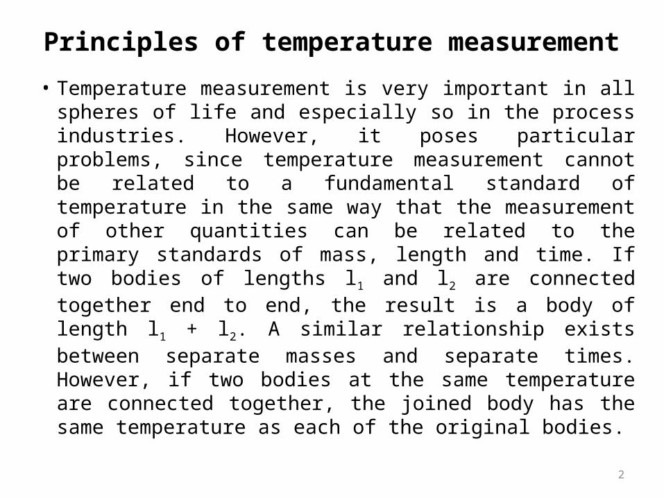
• In the absence of such a relationship, it is necessary to establish fixed, reproducible reference points for temperature in the form of freezing and boiling points of substances where the transition between solid, liquid and gaseous states is sharply defined.
The International Practical Temperature Scale (IPTS) uses this philosophy and defines six primary fixed points for reference temperatures in terms of:
• the triple point of equilibrium hydrogen _259.34°C• the boiling point of oxygen _182.962°C• the boiling point of water 100.0°C• the freezing point of zinc 419.58°C• the freezing point of silver 961.93°C• the freezing point of gold 1064.43°C
(all at standard atmospheric pressure)
Principles of temperature measurement
4
Instruments to measure temperature can be divided into separate classes according to the physical principle on which they operate. The main principles used are:
• Thermal expansion• The thermoelectric effect• Resistance change• Sensitivity of semiconductor device• Radiative heat emission• Thermography• Resonant frequency change• Sensitivity of fibre optic devices• Acoustic thermometry• Colour change• Change of state of material.
Principles of temperature measurement
5
Thermal Expansion
• Expansion thermometersMost solids and liquids expands when they undergo an increase in temperature. The direct observation of the increase of size, or of the signal from a primary transducer detecting it, is used to indicate temperature in many thermometers.
6
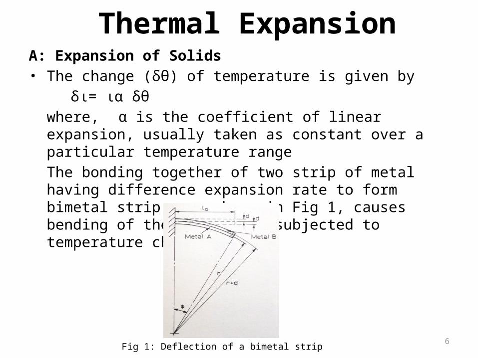
A: Expansion of Solids• The change (δθ) of temperature is given by
δι= ια δθwhere, α is the coefficient of linear expansion, usually taken as constant over a particular temperature range The bonding together of two strip of metal having difference expansion rate to form bimetal strip , as shown in Fig 1, causes bending of the strip when subjected to temperature change.
Thermal Expansion
Fig 1: Deflection of a bimetal strip
7
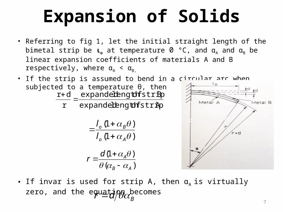
Expansion of Solids• Referring to fig 1, let the initial straight length of the bimetal strip be ιo at
temperature 0 °C, and αA and αB be linear expansion coefficients of materials A and B respectively, where αA < αB,
• If the strip is assumed to bend in a circular arc when subjected to a temperature θ, then
• If invar is used for strip A, then αA is virtually zero, and the equation becomes
A strip oflength expanded
B strip oflength expanded
r
dr
)1(
)1(
Ao
Bo
l
l
)(
)1(
AB
Adr
Bdr
8
Exercise
A bimetal- strip has one end fixed and the other free, the length of the cantilever being 40mm. the thickness of each metal is 1mm, and the element is initially straight at 20 °C. Calculate the movement of the free end in a perpendicular direction from the initial line when the temperature is 180 °C, if one metal is invar and the other is a nickel-chrome-iron alloy with a linear expansion coefficient (α) of 12.5×10⁻⁶/ °C
9
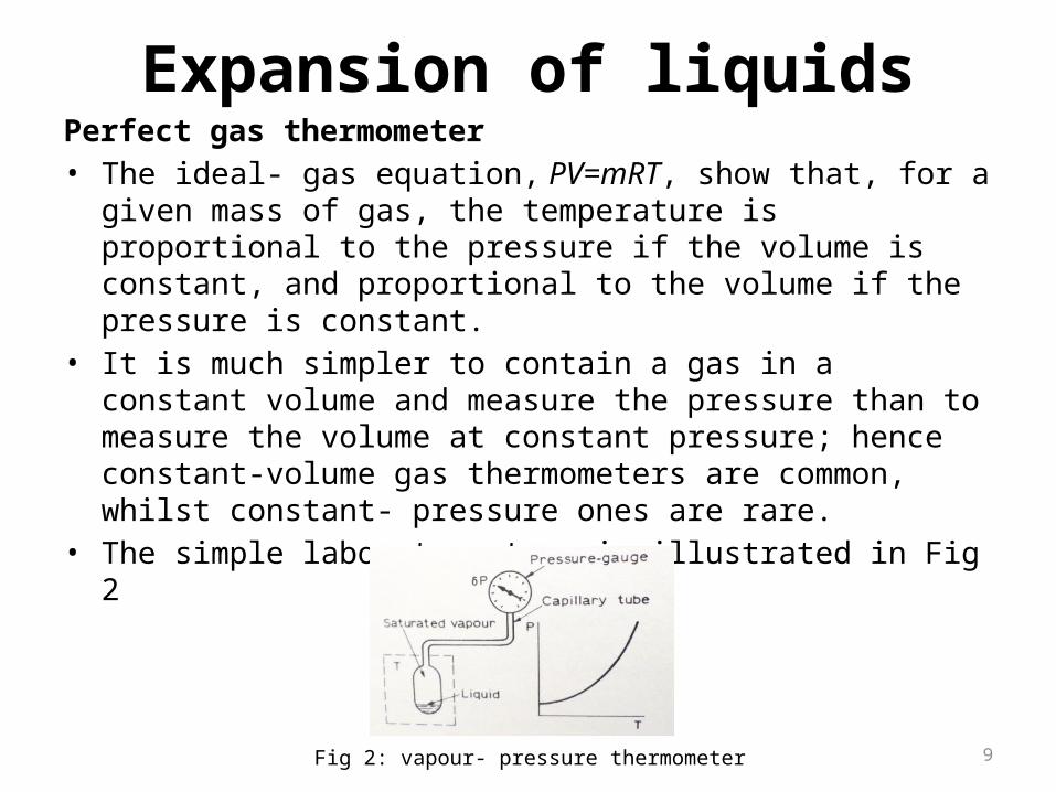
Expansion of liquidsPerfect gas thermometer• The ideal- gas equation, PV=mRT, show that, for a given mass of
gas, the temperature is proportional to the pressure if the volume is constant, and proportional to the volume if the pressure is constant.
• It is much simpler to contain a gas in a constant volume and measure the pressure than to measure the volume at constant pressure; hence constant-volume gas thermometers are common, whilst constant- pressure ones are rare.
• The simple laboratory type is illustrated in Fig 2
Fig 2: vapour- pressure thermometer
10
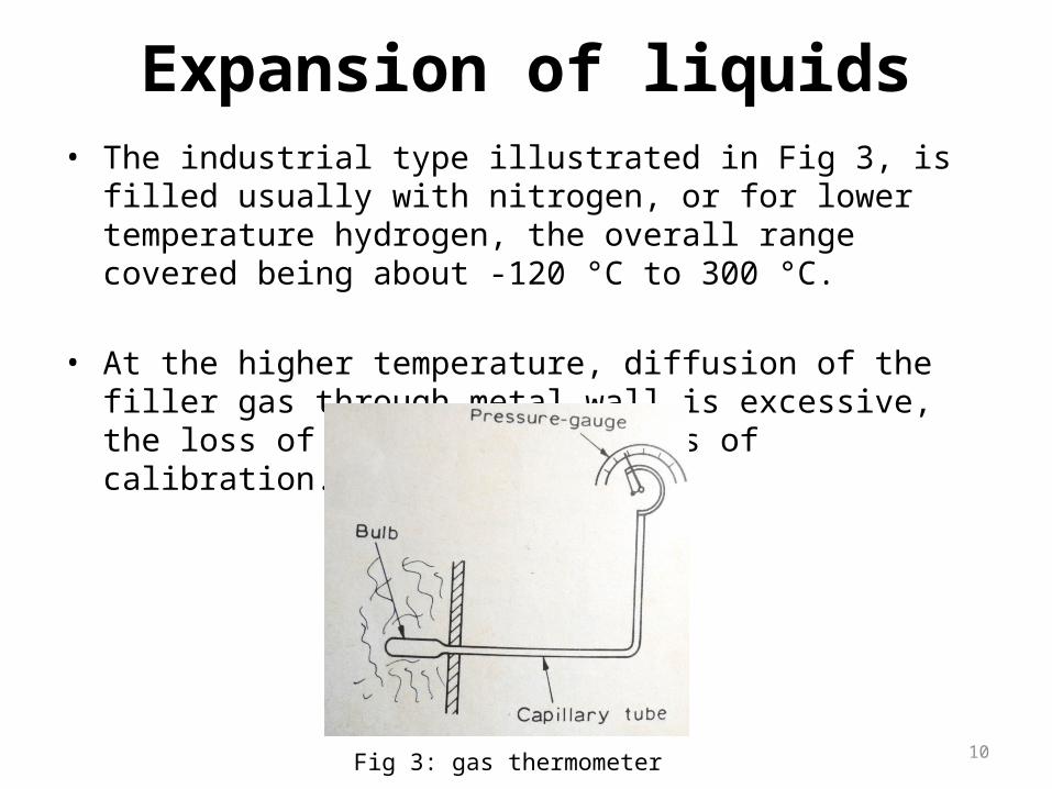
• The industrial type illustrated in Fig 3, is filled usually with nitrogen, or for lower temperature hydrogen, the overall range covered being about -120 °C to 300 °C.
• At the higher temperature, diffusion of the filler gas through metal wall is excessive, the loss of gas leading to loss of calibration.
Expansion of liquids
Fig 3: gas thermometer
11
Thermoelectric effect sensors (thermocouples)
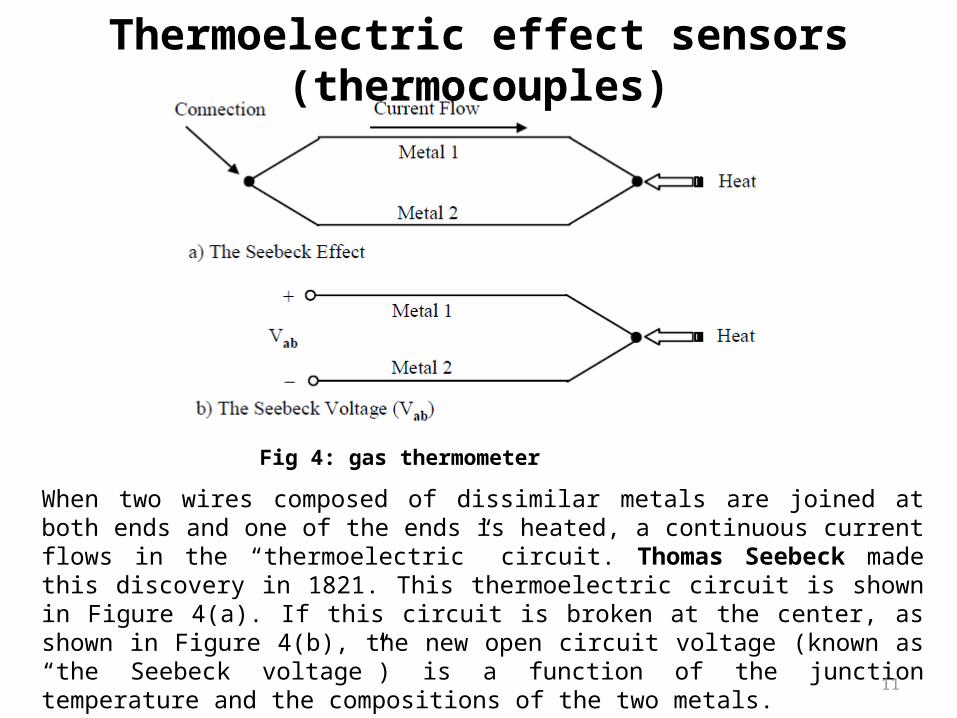
When two wires composed of dissimilar metals are joined at both ends and one of the ends is heated, a continuous current flows in the “thermoelectric” circuit. Thomas Seebeck made this discovery in 1821. This thermoelectric circuit is shown in Figure 4(a). If this circuit is broken at the center, as shown in Figure 4(b), the new open circuit voltage (known as “the Seebeck voltage”) is a function of the junction temperature and the compositions of the two metals.
Fig 4: gas thermometer
12
Thermoelectric effect sensors (thermocouples)
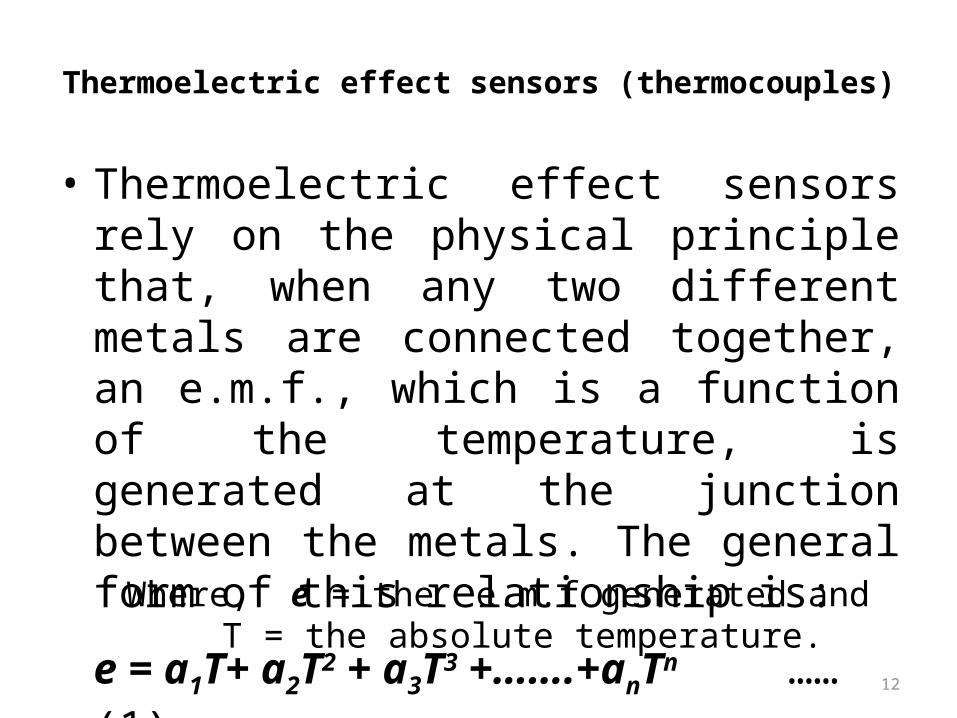
• Thermoelectric effect sensors rely on the physical principle that, when any two different metals are connected together, an e.m.f., which is a function of the temperature, is generated at the junction between the metals. The general form of this relationship is:
e = a1T+ a2T2 + a3T3 +…….+anTn ……(1)
Where, e = the e.m.f generated and T = the absolute temperature.
13
• This is clearly non-linear, which is inconvenient for measurement applications. Fortunately, for certain pairs of materials, the terms involving squared and higher powers of T (a2T2, a3T3 etc.) are approximately zero and the e.m.f.–temperature relationship is approximately linear according to:
e ≈a1T …….(2)
Thermoelectric effect sensors (thermocouples)
Wires of such pairs of materials are connected together at one end, and in this form are known as thermocouples.
Thermocouples are a very important class of device as they provide the most commonly used method of measuring temperatures in industry.
14
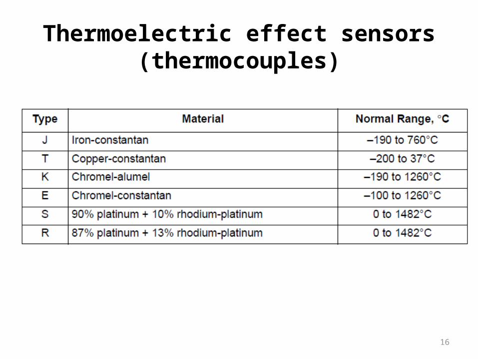
Thermocouples are manufactured from various combinations of
• the base metals copper and iron, • the base-metal alloys of alumel (Ni/Mn/Al/Si), chromel
(Ni/Cr), constantan (Cu/Ni), nicrosil (Ni/Cr/Si) and nisil (Ni/Si/Mn),
• the noble metals platinum and tungsten, and• The noble-metal alloys of platinum/rhodium and
tungsten/rhenium.
Thermoelectric effect sensors (thermocouples)
15
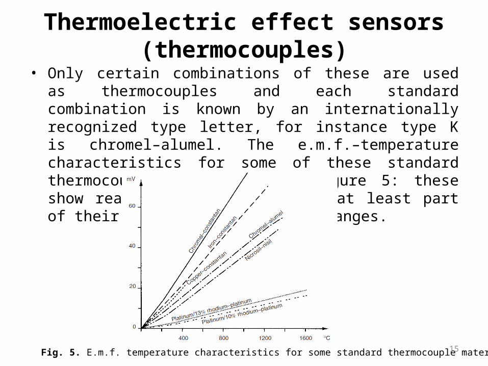
• Only certain combinations of these are used as thermocouples and each standard combination is known by an internationally recognized type letter, for instance type K is chromel–alumel. The e.m.f.–temperature characteristics for some of these standard thermocouples are shown in Figure 5: these show reasonable linearity over at least part of their temperature-measuring ranges.
Fig. 5. E.m.f. temperature characteristics for some standard thermocouple materials.
Thermoelectric effect sensors (thermocouples)
16
Thermoelectric effect sensors (thermocouples)
17
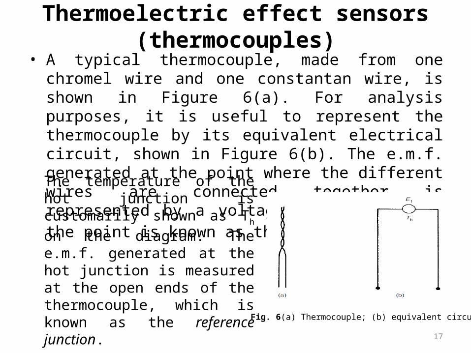
• A typical thermocouple, made from one chromel wire and one constantan wire, is shown in Figure 6(a). For analysis purposes, it is useful to represent the thermocouple by its equivalent electrical circuit, shown in Figure 6(b). The e.m.f. generated at the point where the different wires are connected together is represented by a voltage source, E1, and the point is known as the hot junction.
Fig. 6(a) Thermocouple; (b) equivalent circuit.
The temperature of the hot junction is customarily shown as Th on the diagram. The e.m.f. generated at the hot junction is measured at the open ends of the thermocouple, which is known as the reference junction.
Thermoelectric effect sensors (thermocouples)
18
• In order to make a thermocouple conform to some precisely defined e.m.f.–temperature characteristic, it is necessary that all metals used are refined to a high degree of pureness and all alloys are manufactured to an exact specification.
Thermoelectric effect sensors (thermocouples)
19
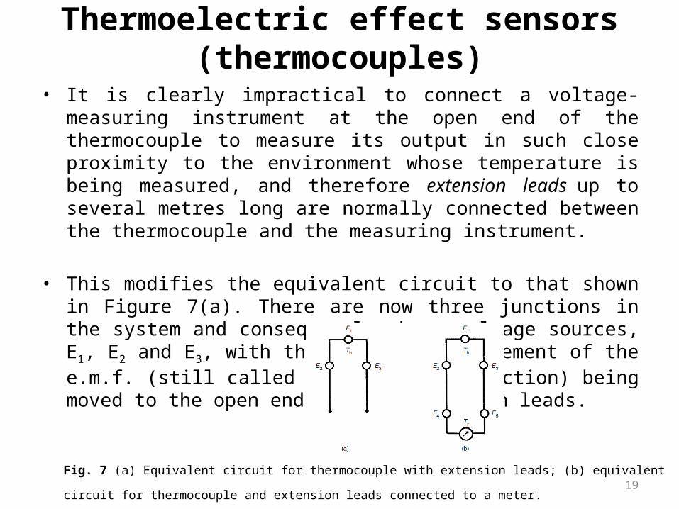
• It is clearly impractical to connect a voltage-measuring instrument at the open end of the thermocouple to measure its output in such close proximity to the environment whose temperature is being measured, and therefore extension leads up to several metres long are normally connected between the thermocouple and the measuring instrument.
• This modifies the equivalent circuit to that shown in Figure 7(a). There are now three junctions in the system and consequently three voltage sources, E1, E2 and E3, with the point of measurement of the e.m.f. (still called the reference junction) being moved to the open ends of the extension leads.
Fig. 7 (a) Equivalent circuit for thermocouple with extension leads; (b) equivalent circuit for thermocouple and extension
leads connected to a meter.
Thermoelectric effect sensors (thermocouples)
20
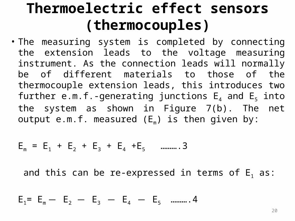
• The measuring system is completed by connecting the extension leads to the voltage measuring instrument. As the connection leads will normally be of different materials to those of the thermocouple extension leads, this introduces two further e.m.f.-generating junctions E4 and E5 into the system as shown in Figure 7(b). The net output e.m.f. measured (Em) is then given by:
Em = E1 + E2 + E3 + E4 +E5 ……….3
and this can be re-expressed in terms of E1 as:
E1= Em ̶ E2 ̶ E3 ̶ E4 ̶ E5 ……….4
Thermoelectric effect sensors (thermocouples)
21
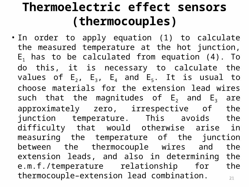
• In order to apply equation (1) to calculate the measured temperature at the hot junction, E1 has to be calculated from equation (4). To do this, it is necessary to calculate the values of E2, E3, E4 and E5. It is usual to choose materials for the extension lead wires such that the magnitudes of E2 and E3 are approximately zero, irrespective of the junction temperature. This avoids the difficulty that would otherwise arise in measuring the temperature of the junction between the thermocouple wires and the extension leads, and also in determining the e.m.f./temperature relationship for the thermocouple–extension lead combination.
Thermoelectric effect sensors (thermocouples)
22
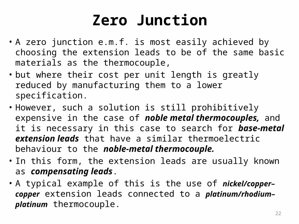
Zero Junction• A zero junction e.m.f. is most easily achieved by choosing the
extension leads to be of the same basic materials as the thermocouple,
• but where their cost per unit length is greatly reduced by manufacturing them to a lower specification.
• However, such a solution is still prohibitively expensive in the case of noble metal thermocouples, and it is necessary in this case to search for base-metal extension leads that have a similar thermoelectric behaviour to the noble-metal thermocouple.
• In this form, the extension leads are usually known as compensating leads.
• A typical example of this is the use of nickel/copper–copper extension leads connected to a platinum/rhodium–platinum thermocouple.
23
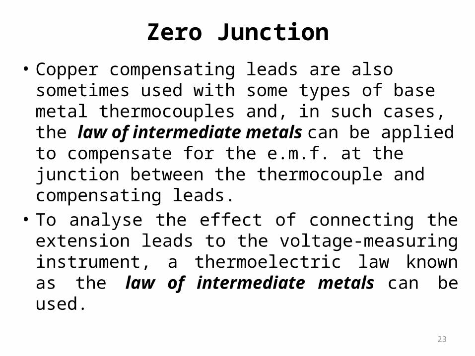
• Copper compensating leads are also sometimes used with some types of base metal thermocouples and, in such cases, the law of intermediate metals can be applied to compensate for the e.m.f. at the junction between the thermocouple and compensating leads.
• To analyse the effect of connecting the extension leads to the voltage-measuring instrument, a thermoelectric law known as the law of intermediate metals can be used.
Zero Junction
24
• To analyse the effect of connecting the extension leads to the voltage-measuring instrument, a thermoelectric law known as the law of intermediate metals can be used.
• This states that “The e.m.f. generated at the junction between two metals or alloys A and C is equal to the sum of the e.m.f. generated at the junction between metals or alloys A and B and the e.m.f. generated at the junction between metals or alloys B and C, where all junctions are at the same temperature”. This can be expressed more simply as:
eAC =eAB + eBC……………… (5)
Zero Junction
25
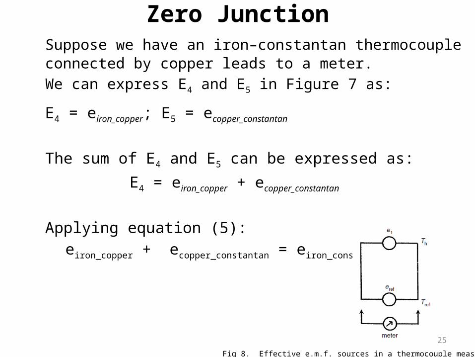
Suppose we have an iron–constantan thermocouple connected by copper leads to a meter. We can express E4 and E5 in Figure 7 as:
E4 = eiron_copper; E5 = ecopper_constantan
The sum of E4 and E5 can be expressed as:
E4 = eiron_copper + ecopper_constantan
Applying equation (5): eiron_copper + ecopper_constantan = eiron_constantan
Zero Junction
Fig 8. Effective e.m.f. sources in a thermocouple measurement system.
26
• Thus, the effect of connecting the thermocouple extension wires to the copper leads to the meter is cancelled out, and the actual e.m.f. at the reference junction is equivalent to that arising from an iron–constantan connection at the reference junction temperature, which can be calculated according to equation (1). Hence, the equivalent circuit in Figure 7(b) becomes simplified to that shown in Figure 8. The e.m.f. Em measured by the voltage-measuring instrument is the sum of only two e.m.f.s, consisting of the e.m.f. generated at the hot junction temperature E1 and the e.m.f. generated at the reference junction temperature Eref. The e.m.f. generated at the hot junction can then be calculated as:
• Eref can be calculated from equation (1) if the temperature of the reference junction is known.
Zero Junction
27
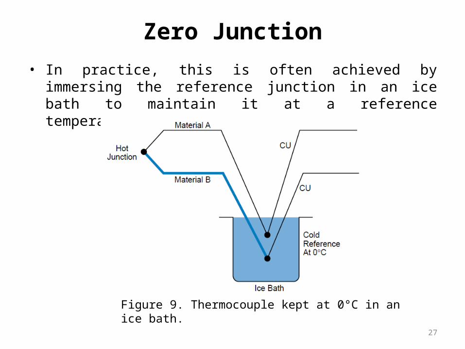
• In practice, this is often achieved by immersing the reference junction in an ice bath to maintain it at a reference temperature of 0°C. (Fig 9)
Zero Junction
Figure 9. Thermocouple kept at 0°C in an ice bath.
28
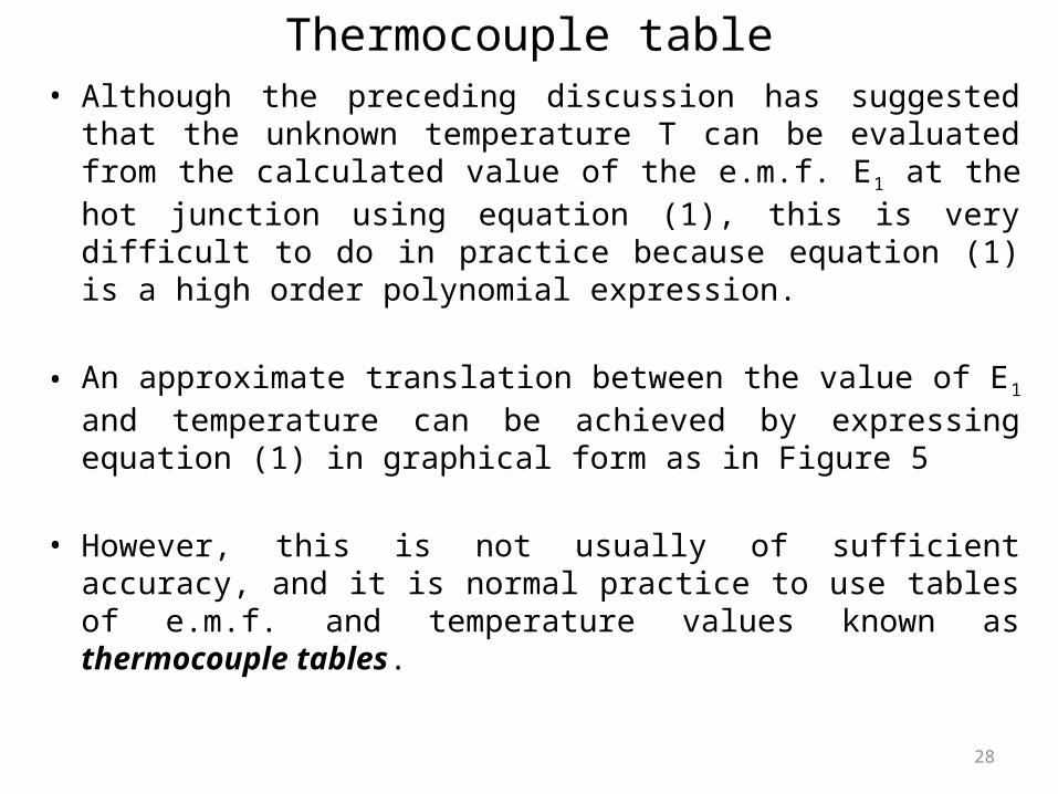
Thermocouple table• Although the preceding discussion has suggested that the
unknown temperature T can be evaluated from the calculated value of the e.m.f. E1 at the hot junction using equation (1), this is very difficult to do in practice because equation (1) is a high order polynomial expression.
• An approximate translation between the value of E1 and temperature can be achieved by expressing equation (1) in graphical form as in Figure 5
• However, this is not usually of sufficient accuracy, and it is normal practice to use tables of e.m.f. and temperature values known as thermocouple tables.
29
• These include compensation for the effect of the e.m.f. generated at the reference junction (Eref), which is assumed to be at 0°C. Thus, the tables are only valid when the reference junction is exactly at this temperature.
Thermocouple table
30
• Example 1If the e.m.f. output measured from a chromel–constantan thermocouple is 13.419mV with the reference junction at 0°C, the appropriate column in the tables shows that this corresponds to a hot junction temperature of 200°C.
Thermocouple table
31
• Example 2If the measured output e.m.f. for a chromel–constantan thermocouple (reference junction at 0°C) was 10.65 mV, it is necessary to carry out linear interpolation between the temperature of 160°C corresponding to an e.m.f. of 10.501mV shown in the tables and the temperature of 170°C corresponding to an e.m.f. of 11.222 mV. This interpolation procedure gives an indicated hot junction temperature of 162°C.
Thermocouple table
32
Resistance temperature detectors (RTDs)
33
RTDs
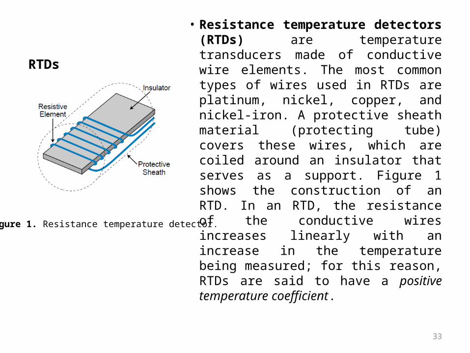
• Resistance temperature detectors (RTDs) are temperature transducers made of conductive wire elements. The most common types of wires used in RTDs are platinum, nickel, copper, and nickel-iron. A protective sheath material (protecting tube) covers these wires, which are coiled around an insulator that serves as a support. Figure 1 shows the construction of an RTD. In an RTD, the resistance of the conductive wires increases linearly with an increase in the temperature being measured; for this reason, RTDs are said to have a positive temperature coefficient.
Figure 1. Resistance temperature detector.

34
• The resistance of most metals increases in a reasonably linear way with temperature (Figure 2) and can be represented by the equation:
Figure 2: Resistance variation with temperature for metals
RTDs
35
RTDsResistance temperature detectors (RTDs) are simple resistive elements in the form of coils of metal wire, e.g. platinum, nickel or copper alloys.
Platinum detectors have • high linearity,• good repeatability, • high long term stability,• can give an accuracy of ±0.5% or
better, • a range of about -200 °C to +850 °C, • Can be used in a wide range of
environments without deterioration, but are more expensive than the other metals. They are, however, very widely used.
Nickel and copper alloys are • Cheaper but have less
stability, are more prone to interaction with the environment and cannot be used over such large temperature ranges
36
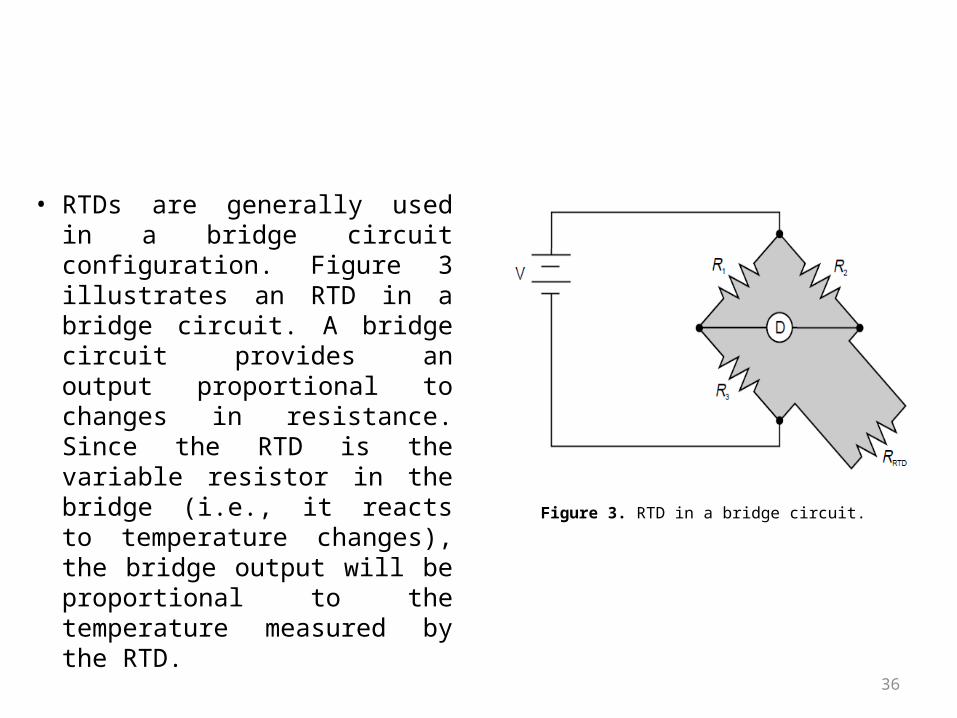
• RTDs are generally used in a bridge circuit configuration. Figure 3 illustrates an RTD in a bridge circuit. A bridge circuit provides an output proportional to changes in resistance. Since the RTD is the variable resistor in the bridge (i.e., it reacts to temperature changes), the bridge output will be proportional to the temperature measured by the RTD.
Figure 3. RTD in a bridge circuit.
37
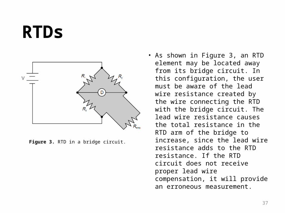
• As shown in Figure 3, an RTD element may be located away from its bridge circuit. In this configuration, the user must be aware of the lead wire resistance created by the wire connecting the RTD with the bridge circuit. The lead wire resistance causes the total resistance in the RTD arm of the bridge to increase, since the lead wire resistance adds to the RTD resistance. If the RTD circuit does not receive proper lead wire compensation, it will provide an erroneous measurement.
Figure 3. RTD in a bridge circuit.
RTDs
38
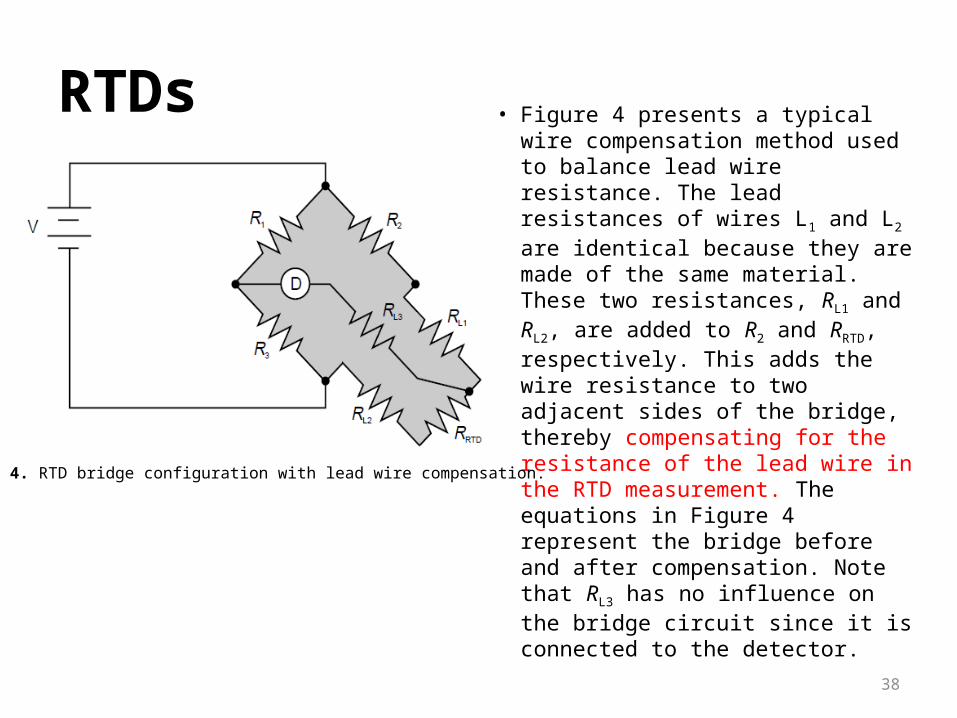
• Figure 4 presents a typical wire compensation method used to balance lead wire resistance. The lead resistances of wires L1 and L2 are identical because they are made of the same material. These two resistances, RL1 and RL2, are added to R2 and RRTD, respectively. This adds the wire resistance to two adjacent sides of the bridge, thereby compensating for the resistance of the lead wire in the RTD measurement. The equations in Figure 4 represent the bridge before and after compensation. Note that RL3 has no influence on the bridge circuit since it is connected to the detector.
Figure 4. RTD bridge configuration with lead wire compensation.
RTDs
39
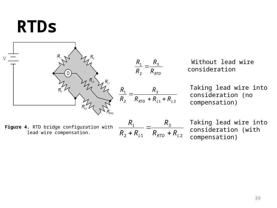
Figure 4. RTD bridge configuration with lead wire compensation.
RTDs
RTDR
R
R
R 3
2
1
21
3
2
1
LLRTD RRR
R
R
R
2
3
12
1
LRTDL RR
R
RR
R
Without lead wire consideration
Taking lead wire into consideration (no compensation)
Taking lead wire into consideration (with compensation)
40
THERMISTORS
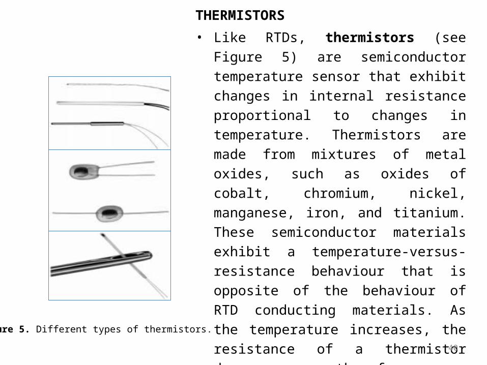
• Like RTDs, thermistors (see Figure 5) are semiconductor temperature sensor that exhibit changes in internal resistance proportional to changes in temperature. Thermistors are made from mixtures of metal oxides, such as oxides of cobalt, chromium, nickel, manganese, iron, and titanium. These semiconductor materials exhibit a temperature-versus-resistance behaviour that is opposite of the behaviour of RTD conducting materials. As the temperature increases, the resistance of a thermistor decreases; therefore, a thermistor is said to have a negative temperature coefficient. Although most thermistors have negative coefficients, some do have positive temperature coefficients.
Figure 5. Different types of thermistors.
Related Documents