1999 Microchip Technology Inc. DS00715A-page 1 Measure Tilt Using PIC16F84A & ADXL202 INTRODUCTION Recent advances in accelerometer sensor technology, especially with silicon micromachined types, have driven the cost of these devices down significantly. As of today, you could obtain an accelerometer for less than $5 per axis. Measurement of acceleration or one of the derivative properties such as vibration, shock, or tilt has become very commonplace in a wide range of products. At first you might think of seismic activity or machinery performance monitoring, but would auto- motive airbags, sports training products, or computer peripherals ever cross your mind? The technology behind acceleration sensors has advanced to provide a very cost effective and user friendly solution for almost any application. There are many types of sensors that measure accel- eration, vibration, shock, or tilt. These sensors include piezo-film, electromechanical servo, piezoelectric, liq- uid tilt, bulk micromachined piezo resistive and capaci- tive sensors, as well as surface micromachined capacitive. Each of these sensors has distinct charac- teristics in the output signal of the sensor, cost to develop, and type of operating environment. Measure- ment of acceleration can also provide velocity by single integration and position by double integration. Vibration and shock can be used for machine health determina- tion as well as motion and shock detection for car alarms. Static acceleration due to gravity can be used to determine tilt and inclination provided that the sensor is responsive to static acceleration. This application note will focus on the surface micro- machined capacitive ADXL accelerometers from Ana- log Devices, in particular the ADXL202. The example application will use the ADXL202 accelerometer with the PIC16F84A in a tilt meter. The PIC16F84A is a good match with the ADXL202 because all acceleration measurements are digital only. Secondly, the Data EEPROM can be used to store the calibration con- stants and restore on reset. The external interface can also be changed easily to accommodate a LCD display (as shown in this application note) or a serial interface to the outside world. MEMs SENSOR: THEORY OF OPERATION In recent years the silicon micromachined sensor has made tremendous advancements in terms of cost and level of on-chip integration for acceleration and/or vibration measurements. By implementing additional BiMOS circuitry on-chip, these products not only pro- vide sensor but also signal conditioning in a single package that requires a few external components to complete the circuit. Some manufacturers have taken this approach one step further by converting the analog output of the sensor to a digital format such as duty cycle. This method not only lifts the burden of designing fairly complex analog circuitry for the sensor but also reduces cost and board area. Because of these advances, the micromachined accelerometer is finding its way into such products as joysticks and airbags that were previously impossible due to price or size limita- tions of the sensor. Figure 1 shows the block diagram of the ADXL202. Author: Rodger Richey Microchip Technology Inc. AN715

Welcome message from author
This document is posted to help you gain knowledge. Please leave a comment to let me know what you think about it! Share it to your friends and learn new things together.
Transcript

1999 Microchip Technology Inc. DS00715A-page 1
Measure Tilt Using PIC16F84A & ADXL202
INTRODUCTIONRecent advances in accelerometer sensor technology,especially with silicon micromachined types, havedriven the cost of these devices down significantly. Asof today, you could obtain an accelerometer for lessthan $5 per axis. Measurement of acceleration or oneof the derivative properties such as vibration, shock, ortilt has become very commonplace in a wide range ofproducts. At first you might think of seismic activity ormachinery performance monitoring, but would auto-motive airbags, sports training products, or computerperipherals ever cross your mind? The technologybehind acceleration sensors has advanced to provide avery cost effective and user friendly solution for almostany application.
There are many types of sensors that measure accel-eration, vibration, shock, or tilt. These sensors includepiezo-film, electromechanical servo, piezoelectric, liq-uid tilt, bulk micromachined piezo resistive and capaci-tive sensors, as well as surface micromachinedcapacitive. Each of these sensors has distinct charac-teristics in the output signal of the sensor, cost todevelop, and type of operating environment. Measure-ment of acceleration can also provide velocity by singleintegration and position by double integration. Vibrationand shock can be used for machine health determina-tion as well as motion and shock detection for caralarms. Static acceleration due to gravity can be usedto determine tilt and inclination provided that the sensoris responsive to static acceleration.
This application note will focus on the surface micro-machined capacitive ADXL accelerometers from Ana-log Devices, in particular the ADXL202. The exampleapplication will use the ADXL202 accelerometer withthe PIC16F84A in a tilt meter. The PIC16F84A is agood match with the ADXL202 because all accelerationmeasurements are digital only. Secondly, the DataEEPROM can be used to store the calibration con-stants and restore on reset. The external interface canalso be changed easily to accommodate a LCD display(as shown in this application note) or a serial interfaceto the outside world.
MEMs SENSOR: THEORY OF OPERATIONIn recent years the silicon micromachined sensor hasmade tremendous advancements in terms of cost andlevel of on-chip integration for acceleration and/orvibration measurements. By implementing additionalBiMOS circuitry on-chip, these products not only pro-vide sensor but also signal conditioning in a singlepackage that requires a few external components tocomplete the circuit. Some manufacturers have takenthis approach one step further by converting the analogoutput of the sensor to a digital format such as dutycycle. This method not only lifts the burden of designingfairly complex analog circuitry for the sensor but alsoreduces cost and board area. Because of theseadvances, the micromachined accelerometer is findingits way into such products as joysticks and airbags thatwere previously impossible due to price or size limita-tions of the sensor. Figure 1 shows the block diagramof the ADXL202.
Author: Rodger RicheyMicrochip Technology Inc.
AN715

AN715
DS00715A-page 2 1999 Microchip Technology Inc.
FIGURE 1: ADXL202 BLOCK DIAGRAM
A surface micromachined device is composed ofsprings, masses and motion sensing components.These sensors use standard integrated circuit process-ing techniques in standard wafer fabs, i.e., no additionalcost to the user for special processes or fabs. As shownin Figure 2, normal IC processes take place by apply-ing layers of oxide and polysilicon. Then using IC pho-tolithography and selective etching the sensor iscreated as a 3-dimensional structure suspended abovethe substrate free to move in all directions. The sur-rounding area becomes the signal conditioning andoutput circuitry.
FIGURE 2: SILICON STRUCTURE OF ADXL202 (SIDE VIEW)
The core of the sensor is a surface micromachinedpolysilicon structure or mass that is suspended on topof the silicon wafer for each axis. The polysilicon"springs" hold the mass and provides resistance tomovement due to acceleration forces. Both the massand the substrate have plates that form a differentialcapacitor where the fixed plates on the substrate aredriven 180° out of phase. Figure 3 shows an exagger-ated diagram of the sensor. Any movement of the massunbalances the differential capacitor resulting in asquare wave output with the amplitude proportional tothe acceleration. Each axis has a demodulator that rec-tifies the signal and determines the direction of theacceleration. This output is fed to a duty cycle modula-tor (DCM) that incorporates external capacitors to setthe bandwidth of each axis. The analog signal is filteredand converted to a duty cycle output by the DCM. Anexternal resistor sets the period of the duty cycle out-put. A 0g acceleration produces a 50% duty cycle out-put. A low-cost, all digital, microcontroller can be usedto measure acceleration by timing both the duty cycleand the period of each axis. Refer to Figure 1 for inter-action and connections between the various circuitsinside the device as described above.
Some of the advantages with micromachined sensorsare that they are low cost and most have on-chip signalconditioning.
Counter
10
9
Cy
11
Rset
5
312
Cx
1413
4 7
+3.0V to +5.25V
Oscillator
Demod
Demod
CDC
100 ohm
VDD VDD XFilt Self Test
X Out
Y Out
DutyCycleModulator(DCM)
32kRfilt
Rfilt32k
X Sensor
Y Sensor
Com YFilt T2
uPADXL202
SUBSTRATE
SENSOR
SAC OXIDE
SUBSTRATE
SENSOR

AN715
1999 Microchip Technology Inc. DS00715A-page 3
FIGURE 3: SENSOR MECHANICAL OPERATION
CONFIGURING THE ADXL202The end application for our ADXL202 is a simple tiltmeter that shows X-axis and Y-axis tilt (or pitch and rollfor you aeronautical buffs). The design procedure issomewhat iterative since the bandwidth, period, andmicrocontroller counter resolution play important rolesin the minimum resolution of the measurement. AnalogDevices has simplified the design procedure by provid-ing an Excel spreadsheet entitled "The XL202 Interac-tive Designer" that can be downloaded off their websiteat www.analog.com and is shown in Appendix A. Thespecifications for our system are +5VDC operation,+/-1.0 degree tilt resolution, 25 samples per channelper second, and the microcontroller should operate at4MHz or less.
Through the use of an iterative process, the designercan determine the external component values and thenoise and resolution of the acceleration measurementwithout having to prototype a single circuit.
In Step 1of the spreadsheet shown in Appendix A, thedesigner will enter the supply voltage which should bebetween 3.0V and 5.25V. We will enter 5.0V. Analogbandwidth is entered in Step 2, which calculates thevalues for the external capacitors. The bandwidthdirectly determines the noise floor and resolution of theaccelerometer and therefore may have to be adjustedto provide the desired results based on calculationslater in the spreadsheet. Enter 10Hz and the resultingcapacitance is 0.50µF. Since 0.50µF is not a standard,we can modify the bandwidth to get a standard value.Using 10.5Hz yields a capacitor of 0.47µF.
In Step 3, the spreadsheet calculates the RMS andpeak-to-peak (P-P) noise of the acceleration measure-ments. The designer must estimate the amount of timethat the actual signal will be above the P-P noise usinga multiplier. At this step enter 4, which in turn reveals
that the peak-to-peak noise will be 0.46 degrees of tilt.Now the designer must evaluate the P-P noise estima-tion because this noise determines the smallest accel-eration resolution that the accelerometer can have. Ifthis noise estimation is not acceptable, then the band-width must be lowered to reduce the P-P noise. Thisexample is well within the 1.0 degree specification andso we will continue.
The next few steps set the period of the duty cycle out-put and the measurement resolution due to the counteron the microcontroller. Both the sample rate per chan-nel and the percentage of time the ADXL202 will bepowered are entered in Step 4. The designer alsoenters the time required to calculate the accelerationfor two channels and the spreadsheet then calculatesthe period of the duty cycle output and the correspond-ing external resistor. We will use 25 samples per sec-ond per channel and the part will be powered up 100%of the time. Analog Devices has already calculated thetime to acquire two channels and perform the calcula-tions as 20ms. Of this time, it takes 3ms for calculationsbased on a previous application note, leaving 17ms forsignal acquisition. This relates to 17,000 instructioncycles on the PICmicro® running at 4MHz.
In Step 5, the counter rate of the microcontroller is usedto calculate the measurement resolution due to thecounter in g’s and degrees of tilt. The spreadsheet alsodetermines the size of the counter on the microcontrol-ler to prevent an overflow. Per our specifications, themicrocontroller is clocked at 4MHz resulting in a 1MHztimer frequency (Timer0). With this timer rate, the res-olution of the digital section of the ADXL202 is 0.06degrees of tilt. The counter required to acquire the dig-ital output must be 15-bits. We can easily implement a15-bit counter using the Timer0 as the low byte of thecount and for each Timer0 overflow increment an upperbyte counter. The designer must again determine if this
PROOF MASS(BEAM) TETHER
FIXEDOUTERPLATES
ANCHOR
APPLIEDACCELERATION
CS1<CS2
TOP VIEW
AN715
DS00715A-page 4 1999 Microchip Technology Inc.
resolution is acceptable. To increase the resolution,either increase the counter rate (Step 5) or decreasethe number of samples per second (Step 4).
Step 6 checks for aliasing errors due to the sample rate.Nyquist requirements specify that the sample rateneeds to be faster than the bandwidth by a factor of 2.Analog Devices recommends that at least a factor of 10is used to minimize dynamic errors from the PWM sam-pling technique. For our case the, the ratio is 11.2 whichaccording to Nyquist and Analog Devices is more thansufficient. If the spreadsheet calculates that the ratio islow, the designer must increase the sample rate in Step4 or decrease the bandwidth in Step 2.
The results are in! The spreadsheet calculates theminimum resolution of the acceleration measurementdue to RMS P-P noise and resolution of the counter inStep 7. It also provides a minimum resolution of a tiltmeasurement. Our calculated minimum resolution is0.5 degrees of tilt which is acceptable according to thespecification. If this resolution was not acceptable, thenthe bandwidth (Step 2), acquisition rate (Step 4), or thecounter rate (Step 5) would have to be adjusted toreduce noise.
The spreadsheet also offers the designer the ability toexplore how oversampling the PWM signal affectsnoise at the expense of sacrificing bandwidth in Step 8.Finally, Step 9 provides the estimated drift of the 0 gpoint due to temperature effects.
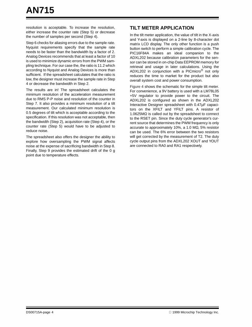
TILT METER APPLICATIONIn the tilt meter application, the value of tilt in the X-axisand Y-axis is displayed on a 2-line by 8-character dotmatrix LCD display. The only other function is a pushbutton switch to perform a simple calibration cycle. ThePIC16F84A makes an ideal companion to theADXL202 because calibration parameters for the sen-sor can be stored in on-chip Data EEPROM memory forretrieval and usage in later calculations. Using theADXL202 in conjunction with a PICmicro® not onlyreduces the time to market for the product but alsooverall system cost and power consumption.
Figure 4 shows the schematic for the simple tilt meter.For convenience, a 9V battery is used with a LM78L05+5V regulator to provide power to the circuit. TheADXL202 is configured as shown in the ADXL202Interactive Designer spreadsheet with 0.47µF capaci-tors on the XFILT and YFILT pins. A resistor of1.0625MΩ is called out by the spreadsheet to connectto the RSET pin. Since the duty cycle generator’s cur-rent source that determines the PWM frequency is onlyaccurate to approximately 10%, a 1.0 MΩ, 5% resistorcan be used. The 6% error between the two resistorswill get corrected by the measurement of T2. The dutycycle output pins from the ADXL202 XOUT and YOUTare connected to RA0 and RA1 respectively.

AN
715
1999 M
icrochip Technology Inc.
DS
00715A-page 5
FIGURE 4: TILT METER SCHEMATIC
Date: June 21, 1999 Sheet 1 of 1
Size Document Number REVA TILT.SCH 1
TitleTILT SENSOR
Microchip Technology Incorporated
C60.47UF
C70.47UF
VDDC3
0.1UF
NC 1
VTP 2
ST 3
VSS 4
T2 5
NC 6
VSS 7 NC 8YOUT 9XOUT 10YFILT 11XFILT 12VDD13VDD 14
U2
ADXL202
R31.0M
VDDVDD
R1
10K
1 23 45 67 89 1011 1213 14
JP2
LCD
VDDVDD
C1
0.1UF
C433PF
C533PF
Y1
4MHz
RA2 1RA3 2RA4/T0CKI 3MCLR 4VSS
5RB0/INT 6RB1 7RB2 8RB3 9 RB4 10RB5 11RB6 12RB7 13VDD
14OSC2 15OSC1 16RA0 17RA1 18U1
PIC16F84A
R5100
R410K
C80.1UF
VDD
C20.1UF
VIN 3 VOUT 1GND2
VR178L05
BT19V
S1
SW

AN715
DS00715A-page 6 1999 Microchip Technology Inc.
The microcontroller circuit is also very simple. The4MHz crystal uses two 33pF capacitors to complete theoscillator circuit. The push button switch is connectedto RB4. This pin has internal pull-up resistors reducingthe need for any external circuitry. The LCD display isdriven using the 4-bit MPU mode which only requires 3I/O pins for control and 4 I/O pins for data. Refer to thespecifications for the Hitachi HD44780 LCD controlleror the application note, AN587, "Interfacing PICmi-cros® to an LCD Module", for more interface informa-tion. The controls lines RS, R/W, and E connect to RB5,RA3, and RA2. The data lines are connected toRB<0:3>. There is also a 10ΚΩ potentiometer con-nected to pin 3 of the LCD display to control the con-trast.
Acceleration is a vector quantity with both a directionand magnitude. The acceleration vector can be brokenup into two vectors on the ADXL202, the X-axis andY-axis. The ADXL202 is responsive to both static accel-eration due to gravity as well as acceleration due tomotion. The main problem with using this type ofaccelerometer to measure degrees tilt is not that it issensitive to motion but that it can’t distinguish betweengravity and motion. The user must implement sometype of time weighted filter to remove the effects ofmotion from the measurement (not implemented in thisdesign). When the tilt angle is varied along the sensitiveX- and Y-axis, the acceleration vector changes and theADXL202 responds by changing the duty cycle out-puts. The angle of tilt is defined by the followingequation:
θ = arcsin[ (V(out)-V(zero g)) / (1g x Scale factor(V/g)) ]
This is a difficult calculation on an 8-bit microcontroller,therefore the calculation will be simplified. In spite ofthis, we still yield very good results (shown later in thefirmware section).
The firmware is centered around the duty cycle mea-surement. The technical note from Analog Devicestitled "Using the ADXL202 Duty Cycle Output" shows avery efficient method of measuring the period and dutycycle of the PWM waveforms. Figure 5 shows thewaveforms from XOUT and YOUT. The most obviousmethod of measuring these waveforms is to measurethe time from rising edge to falling edge to next risingedge for each of the waveforms. While very simple, thismethod takes 3 complete cycles to complete the pro-cess. If you take a closer look at Figure 5, you will seethat the high time of XOUT and YOUT are centeredabout each other. We can use this to our advantage.
Figure 6 shows the waveform and measurement pointsfor the improved measurement scheme. At Ta thecounter is started. The program then records the timesat Tb, Tc, and Td. By looking at the points of Figure 6,we can say that:
T1x = Tb - Ta = Tb (counter was 0 at Ta)
T1y = Td - Tc
T2x = T2y = T2 = Te - Ta = Tg - Tf
Since we have already established that the center of T1is aligned with the center of T2, the equation for T2reduces to:
T2 = Td - T1y/2 - T1x/2
T2 = Td - (Td - Tc)/2 - Tb/2
This technique not only reduces the measurement timeto two cycles, it also only calculates T2 once.
FIGURE 5: ADXL202 DUTY CYCLE OUTPUT
X Out
Y Out

AN715
1999 Microchip Technology Inc. DS00715A-page 7
FIGURE 6: ADXL202 DUTY CYCLE MEASUREMENT
Now that our system is reading the duty cycle outputsof the ADXL202 and displaying the results on the LCDdisplay, we need to consider how the system is cali-brated. The first calibration step is the initial calibrationof the tilt sensor with respect to gravity. The simplestmethod is to position the system such that the X-axisand Y-axis are both level. When instructed to calibrate,the PIC16F84A will calculate the duty cycle output T1for both axis and the period T2. Several readings maybe taken and averaged to improve the accuracy of themeasurements. These values are now stored in bothRAM as well as EEPROM as calibration constants. Ascale factor is also used in the calibration process tocreate an n-bit result. These constants are defined as:
• T2cal, the value of T2 during the calibration phase. T2 must be stored because it can vary over temperature and has jitter from one mea-surement to another.
• ZXcal, the value of T1x during the calibration phase.
• ZYcal, the value of T1y during the calibration phase.
• K, the scale factor and is equal to [4 * (T2cal * bit_scale_factor) / T2cal]
K needs to be calculated only once. Since each axiswill use this factor it is hard coded in the firmware. Thebit_scale_factor is used to determine the size of theresult. Since we are looking for a result of +/- 90 (1degree of tilt per count), the bit scale factor would be180. Therefore, K is assigned a value of 720. This isthe simplification that was mentioned earlier.
Once we have calculated the calibration constants wecan apply them to the duty cycle measurements to getdegree of tilt. The following formulas give the degree oftilt for each axis:
ZXactual = ( ZXcal * T2actual ) / T2cal (1)
ZYactual = (ZYcal * T2actual ) / T2cal (2)
T2actual is the current measurement of T2. Thisformula adjusts the 0g value for changes in T2 due totemperature or jitter.
XAcceleration = [ K * (T1x - ZXactual) ] / T2actual (3)
YAcceleration = [ K * (T1y - ZYactual) ] / T2actual (4)
The values of T1x and T1y are the current measure-ments of T1 for each axis. The results in XAccelerationand YAcceleration are the degrees to tilt in the X-axisand Y-axis directions properly scaled for 1 degree percount. This method of calibration is very simple yet willsuffer from small errors due to variance in duty cycle %per g (which was assumed to be 12.5%) from one partto the next.
X Out
Y Out
T1x
T2
Ta Tb
T1yTc Td
T2
Tg Tf

AN715
DS00715A-page 8 1999 Microchip Technology Inc.
The order of the math operations is deliberate to pre-serve the accuracy of the result. All math operationsare done in fixed point math. Several variables areused in the math operations. The following table showsthe two inputs to each routine and the location of theresult of the routine.
TABLE 1: MATH OPERATIONS VARIABLE USAGE
For calculating Zactuals in formula (1) and (2), the 16 x16 multiply of Zcal * T2actual takes place first followedby the division of the result by T2cal. When calculatingtilt (really is scaled acceleration) in the formulas (3) and(4), the subtraction of Zactual from T1 takes place first,followed by multiplication of the result by K, and finallythe division of the result by T2actual.
Finally, the last two pieces of the code are for the LCDdisplay and the Data EEPROM access. The LCD codeis a derivative of that found in the application note,AN587, "Interfacing PICmicro® Microcontrollers to anLCD Module". Most of the changes were related to thedifferent I/O pins used for data and control. The DataEEPROM routines use code directly from thePIC16F84A data sheet DS35007 for reads and writes.The WriteCal routine takes the calibration constantsand writes them to the Data EEPROM. This routine isonly called when a calibration cycle is performed. TheRestoreCal routine is called when the PIC16F84A isreset. The calibration constants are grouped sequen-tially in memory so that these routines can use indirectaddressing and shorten the length of code.
CONCLUSIONAs in all applications, the type of acceleration sensordepends on the system requirements as well as theproperty being measured. Some accelerometers arebetter suited towards measuring vibration and shocksuch as the piezo-film and piezoelectric. Others areused for tilt measurements such as liquid tilt and micro-machined types. The type of sensor selected then dic-tates the signal conditioning circuitry requirements.Some accelerometers have AC response, some DC.Some sensors have analog outputs, others digital. Inother words, one accelerometer does not fit into allapplications. This application note has shown that adesigner can quickly and easily complete an acceler-ometer based design using the ADXL sensors fromAnalog Devices. The use of a microcontroller furthersimplifies the design by giving the designer a more inte-grated, lower cost solution for the data measurementapplication.
Operation Operand #1 Operand #2 Result
16 x 16 Addition ACCHI, ACCLO ARGH, ARGL ACCHI, ACCLO
16 x 16 Subtraction ACCHI, ACCLO ARGH, ARGL ACCHI, ACCLO
16 x 16 Multiply ACCHI, ACCLO ARGH, ARGL PRODW3, PRODW2, PRODW1, PRODW0
32 x 16 Divide PRODW3, PRODW2, PRODW1, PRODW0
DIV1, DIV0 ANS1, ANS0

AN715
1999 Microchip Technology Inc. DS00715A-page 9
REFERENCES
Data Sheets
• ADXL202 Data Sheet, Analog Devices Inc., Rev. 0• ADXL210 Data Sheet, Analog Devices Inc.,
Rev. Pr.A• PIC16F84A Data Sheet, Microchip Technology Inc.,
DS35007A
Technical Notes From Analog Devices
• Using the ADXL202 Duty Cycle Output• Accelerometer Design and Applications• A Compact Algorithm Using The ADXL202 Duty
Cycle Output• The Interactive Designer ADXL202

AN
715
DS
00715A-page 10
1999 M
icrochip Technology Inc.
APPENDIX A: ADXL202 INTERACTIVE DESIGNER
The XL202 Interactive DesignerEnter values below. When your design is complete the values for your design will print out on this page.
ParametersSupply voltage 5.0 V
Vdd Analog Bandwidth 10.5 HzAcquisition Rate 25 readings per secondResolution (g’s) 0.008 gResolution (deg of tilt) 0.47 deg of tiltMicrocontroller counter rate 1 MHzT2 8.5 mSPower cycling % 100% on timeTmax 35 deg CTmin 15 deg CZero g drift Tmax 0.02 gZero g drift Tmin 0.02 g
Component Values0 Supply Decoupling 0.1 uF
Xcap, Ycap 0.47 uFRset 1062.5 kohm
uP
Counter
X Sensor
Demod
Y Sensor
ADXL202
Vdd
YFilt T2Rset
Com
XFilt
Demod
Oscillator
AnalogtoDutyCycle(ADC)
X Out
Y Out
32k
32k
Self TestVdd
Rfilt
Rfilt
Cx
Cy
100 ohm
You will be asked to enter variety of design parameters important to your applications. This will include such issues as how fast is the signal you need to measure, what is the required update or acquisition rate, what is the counter speed on your microcontroller. After entering target values (inputs) the spreadsheet will calculate outputs such as the resolution of the accelerometer. You can then iterate the input values and trade off parameters as necessary to meet your design goals. Only enter values that are in bold.
Counter
Cy Rset
Cx
VDD
Oscillator
Demod
Demod
100 ohm
VDD VDD XFilt Self Test
X Out
Y Out
Analog toDutyCycle(ADC)
32kRfilt
Rfilt32k
X Sensor
Y Sensor
Com YFilt T2
uPADXL202
0
AN
715
1999 M
icrochip Technology Inc.
DS
00715A-page 11
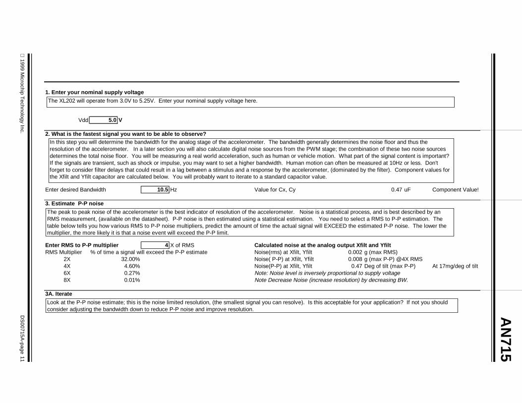
1. Enter your nominal supply voltage
Vdd 5.0 V
2. What is the fastest signal you want to be able to observe?
Enter desired Bandwidth 10.5 Hz Value for Cx, Cy 0.47 uF Component Value!
3. Estimate P-P noise
Enter RMS to P-P multiplier 4 X of RMS Calculated noise at the analog output Xfilt and YfiltRMS Multiplier % of time a signal will exceed the P-P estimate Noise(rms) at Xfilt, Yfilt 0.002 g (max RMS)
2X 32.00% Noise( P-P) at Xfilt, Yfilt 0.008 g (max P-P) @4X RMS4X 4.60% Noise(P-P) at Xfilt, Yfilt 0.47 Deg of tilt (max P-P) At 17mg/deg of tilt6X 0.27% Note: Noise level is inversely proportional to supply voltage8X 0.01% Note Decrease Noise (increase resolution) by decreasing BW.
3A. Iterate
Look at the P-P noise estimate; this is the noise limited resolution, (the smallest signal you can resolve). Is this acceptable for your application? If not you should consider adjusting the bandwidth down to reduce P-P noise and improve resolution.
The XL202 will operate from 3.0V to 5.25V. Enter your nominal supply voltage here.
In this step you will determine the bandwidth for the analog stage of the accelerometer. The bandwidth generally determines the noise floor and thus the resolution of the accelerometer. In a later section you will also calculate digital noise sources from the PWM stage; the combination of these two noise sources determines the total noise floor. You will be measuring a real world acceleration, such as human or vehicle motion. What part of the signal content is important? If the signals are transient, such as shock or impulse, you may want to set a higher bandwidth. Human motion can often be measured at 10Hz or less. Don’t forget to consider filter delays that could result in a lag between a stimulus and a response by the accelerometer, (dominated by the filter). Component values for the Xfilt and Yfilt capacitor are calculated below. You will probably want to iterate to a standard capacitor value.
The peak to peak noise of the accelerometer is the best indicator of resolution of the accelerometer. Noise is a statistical process, and is best described by an RMS measurement, (available on the datasheet). P-P noise is then estimated using a statistical estimation. You need to select a RMS to P-P estimation. The table below tells you how various RMS to P-P noise multipliers, predict the amount of time the actual signal will EXCEED the estimated P-P noise. The lower the multiplier, the more likely it is that a noise event will exceed the P-P limit.

AN
715
DS
00715A-page 12
1999 M
icrochip Technology Inc.
4. How fast would you like to acquire the signals?
Enter desired acquistion rate 25 Each Channel per second Calculate Acquisition TimeMaximum time available to acquire 2 channels 20.0 ms
% of time part will be powered per second 100% Time required to calculate two channels 3.0 msTime left for signal acquisition 17.0 ms (two channels)
This implies a requirement for the value of the PWM period T2Thus, T2 = 8.5 mS or 118 Hz This is the Sample RateValue for Rset 1062.5 kohm Component Value!
5. Enter the counter rate of your Microcontroller and calculate the resolution of the digital output.
Counter Rate 1 Mhz Resolution 1062.5 Counts per gResolution 0.001 g Quantization bit size
Note: you will need a counter of size 17000 counts or 15 bits Resolution 0.06 Deg of Tilt Based on 17mg/deg of tiltTo avoid overflowing the counter Note: Increase resolution by increasing counter rate or decreasing samples per second
6. Check for aliasing and other errors in sampling:
Ratio of sample rate (1/T2) to analog BW: 11.2 Good!
In all cases the sample rate (1/T2) needs to be faster than the bandwidth of the analog section by a factor of at least 2 in order to meet the requirements of Nyquist. Nyquist notwithstanding, a ratio of at least 10 is recommend to minimize dynamic errors that are endemic to PWM sampling techniques. If your ratio is low, you can improve it by either increasing the sample rate (by increasing the acquistion rate in section 4) or decreasing the analog bandwidth ( in section 2).
In this section we will begin the design of the digital output, and the microcontroller interface. You will input an acquisition rate, i.e. how many times per second you want a new reading from the accelerometer. You are also asked how long the part should be powered each second. Note that if you only want a few samples per second, but intend to keep the part powered all of the time, then you will need to set a faster acquisition rate in order to get reasonable values for the PWM output. The program requests that you input the time required to do the multiplies and divides to calculate the acceleration. 3.0ms is the time required for a Microchip 16C63 running at 4 Mhz. This section generates a component value for the Rset resistor.
In Section 2, we calculated the resolution of the analog section. In this section we will calculate the resolution of the digital output; a fuction of the PWM rate T2 (calculated in section 4), and the counting rate of your microcontroller. Please note that the counting rate is different, and usually slower than the microcontroller clock rate. The output of this calculation is a measure of the quantization error of the counter. In some cases it may limit the ultimate resolution; we will explore this in

AN
715
1999 M
icrochip Technology Inc.
DS
00715A-page 13
7. Estimate of total resolution (iterate to meet design objective)
Noise due to analog section 0.008 g (max P-P) @4X RMS This is the noise contribution at the analog output Xcap, YcapResolution of digital output- counter 0.001 g This is the quantization noise of the digital outputEstimated Total Noise (resolution): 0.008 g P-P This is the total P-P noise, which is the root sum square of the analog and digital noise.Estimated Total Noise (resolution): 0.5 deg of tilt @ 17mg/degNoise (Resolution) is limited by: Bandwidth at Xfilt, Yfilt; reduce bandwidth if lower noise desired (section 2)
8. Option: Reduce noise by oversampling (at expense of bandwidth)
Estimated Noise (resolution) with average of: 1 Samples Noise before oversampling 0.008 g P-PNote: Samples should be taken about: 95.2381 mS apart Noise after oversampling 0.008 g P-P 0% Reduction
Bandwidth before oversampling 10.5 HzBandwidth after oversampling 10.5 Hz
9. Estimated Drift of Zero g point
Drift from 25C ValueDrift in mG per degree C 0.002 g/C Drift in mG Drift in deg of tiltMax Temp 35 C at Tmax 0.02 mg 1.2 deg of tilt at 17mg/deg CMin Temp 15 C at Tmin 0.02 mg 1.2 deg of tilt at 17mg/deg C
We are now in a position to bring together the various calculation above to determine the resolution of the complete analog and digital design. The ultimate resolution is determined by both the noise at the analog output (Xcap and Ycap) and the quantization bit size of the PWM + counter system. At this point check the total system resolution to see if it meets your requirements. If it does not, then revisit bandwidth at Xfilt and Yfilt, acquistion rate or counting rate to reduce noise. You may also want to consider digital filtering, (oversampling) to reduce noise at the expense of sampling rate as discussed in the next section.
Another design option is to use digital filtering (averaging) in order to reduce noise, at the expense of bandwidth. By averaging several samples you are in effect filtering the signal. Implementing averages of 2,4 8, 16 samples are simple right shifts in microcontroller code (very efficient). For oversampling to work, samples need to be taken at a rate no faster than 10 times the analog bandwidth. Note: make sure oversampling is set to 1 sample if you don’t want to use oversampling!
You can estimate the zero g temperature shift by entering your expected temperature range below and an estimate of the drift in mg/C (from the data sheet). Note that zero g drift can be positive or negative, but in general is very linear. X axis and Yaxis drift are uncorrelated.

AN715
DS00715A-page 14 1999 Microchip Technology Inc.
APPENDIX B: TILT SENSOR FIRMWARE FLOWCHART
Restore CalibratorConstants
A
B
C
D
Start
Initialize
Check Accel
Read Accel
Find ZActual
Calculate Accel
Display tilt onLCD Display
Delay
A
BRead Accel
Write Cal Datato EEPROM
B
Display CalMessage
T2calHi: T2calLo =T2Hi: T2Lo
ZXcalHi: ZXcalLo =T1XHi: T1XLo
ZYcalHi: ZYcalLo =T1YHi: T1YLo
Display DoneMessage
Return
RB4= 0
N
Y
N RB4= 1
Y
Xout= 0
Xout= 1
N
Y
N
Y
Enable Timer0Interrupts
Clear Timer0
Xout= 0
N
Y
Capture Timer0T1X
Yout= 0
N
Y
Yout= 1
N
Y
Capture Timer0T1Y Start
Yout= 0
N
Y
Capture Timer0T1YEnd
Calculate T1YT1YEnd-T1YStart
Calculate T2
Return
Calibrate ReadingY-Axis
Calibrate ReadingX-Axis
(ZXcal * T2) / T2cal
C
(ZYcal * T2) / T2cal
Return
Calculate Y-AxisTilt
Calculate X-AxisTilt
K * (T1X - ZXactual)
D
Return
T2actual
K * (T1Y - ZYactual)T2actual

AN715
1999 Microchip Technology Inc. DS00715A-page 15
APPENDIX C: TILT MOTOR SOURCE CODE LISTING
00001 list p=16f84a 00002 include <p16f84a.inc> 00001 LIST 00002 ; P16F84A.INC Standard Header File,Version 2.00 Microchip Technology 00134 LIST 00003 2007 3FF1 00004 __config _CP_OFF&_WDT_OFF&_XT_OSC&_PWRTE_ON 00005 ;Assembled using MPASM V2.30 00006 ;PORTA defines 00007 #define XOUT 0 00008 #define YOUT 1 00009 #define E 2 00010 #define RW 3 00011 00012 ;PORTB defines 00013 #define CAL 4 00014 #define RS 5 00015 00016 ;==================================================================== 00017 ; RAM EQUATES 00018 ;==================================================================== 00019 cblock 0x0c 0000000C 00020 T1XHi 0000000D 00021 T1XLo 0000000E 00022 ArgL 0000000F 00023 ArgH 00000010 00024 AccHi 00000011 00025 AccLo 00000012 00026 DivCnt 00000013 00027 PRODW3 00000014 00028 PRODW2 00000015 00029 PRODW1 00000016 00030 PRODW0 00000017 00031 DIV0 00000018 00032 DIV1 00000019 00033 ANS0 0000001A 00034 ANS1 0000001B 00035 T2Hi 0000001C 00036 T2Lo 0000001D 00037 T1YStartLo 0000001E 00038 T1YStartHi 0000001F 00039 T1YEndLo 00000020 00040 T1YEndHi 00000021 00041 T1YHi 00000022 00042 T1YLo 00000023 00043 ZXcalHi 00000024 00044 ZXcalLo 00000025 00045 ZYcalHi 00000026 00046 ZYcalLo 00000027 00047 T2calHi 00000028 00048 T2calLo 00000029 00049 ZXActualHi 0000002A 00050 ZXActualLo 0000002B 00051 ZYActualHi 0000002C 00052 ZYActualLo 0000002D 00053 XAccel 0000002E 00054 YAccel

AN715
DS00715A-page 16 1999 Microchip Technology Inc.
0000002F 00055 Temp0 00000030 00056 Temp1 00000031 00057 Temp2 00000032 00058 Temp3 00000033 00059 Timer0H 00000034 00060 EADR 00000035 00061 EDATA 00062 endc 00063 0000000E 00064 Count1 equ ArgL 0000000F 00065 Count2 equ ArgH 0000002F 00066 Temp equ Temp0 00000019 00067 CMD equ ANS0 00000019 00068 LDATA equ CMD 00000017 00069 Digit0 equ DIV0 00000018 00070 Digit1 equ DIV1 00071 00000002 00072 KHi equ 0x02 000000D0 00073 KLo equ 0xd0 00074 0000 00075 org 0x00000000 2808 00076 goto Start ;Go to start of program 00077 0004 00078 org 0x00040004 0AB3 00079 incf Timer0H,F0005 110B 00080 bcf INTCON,T0IF0006 118B 00081 bcf INTCON,RBIE0007 0009 00082 retfie 00083 0008 00084 Start0008 1283 00085 bcf STATUS,RP00009 0185 00086 clrf PORTA000A 0186 00087 clrf PORTB000B 1683 00088 bsf STATUS,RP0 ;Bank1000C 3003 00089 movlw B’00000011’ ;Set up the I/O ports000D 0085 00090 movwf TRISA000E 3010 00091 movlw B’00010000’000F 0086 00092 movwf TRISB0010 300F 00093 movlw B’00001111’0011 0081 00094 movwf OPTION_REG0012 1283 00095 bcf STATUS,RP0 ;Bank00013 21E1 00096 call OpenXLCD ;Initialize LCD0014 22C6 00097 call RestoreCal ;Restore calibration constants0015 178B 00098 bsf INTCON,GIE 00099 0016 00100 Main0016 20F2 00101 call CheckCal ;Check if need to calibrate0017 2020 00102 call ReadAccel ;Read the acceleration0018 2060 00103 call FindZActual ;Calibrate readings0019 2085 00104 call CalculateAccel ;Calculate tilt (acceleration)001A 2194 00105 call DisplayAccel ;Display results001B 30FF 00106 movlw 0xff ;Delay for a while001C 22A2 00107 call Delay_Ms_4MHz001D 30FF 00108 movlw 0xff001E 22A2 00109 call Delay_Ms_4MHz001F 2816 00110 goto Main ;Do it again 00111 ;******************************************************************** 00112 00113 ;==================================================================== 00114 ;=========== Acceleration Measurement/Calculation Routines ==========

1999 Microchip Technology Inc. DS00715A-page 17
AN715
00115 ;==================================================================== 00116 ;******************************************************************** 00117 ;ReadAccel 00118 ; This subroutine acquires and calculates T1X, T1Y, and T2. 00119 ; T1X is in registers T1XHi,T1XLo 00120 ; T1Y is in registers T1YHi,T1YLo 00121 ; T2 is in registers T2Hi,T2Lo 00122 ;********************************************************************0020 00123 ReadAccel0020 00124 EDGE10020 1805 00125 btfsc PORTA,XOUT ;Wait for low on XOUT0021 2820 00126 goto EDGE10022 00127 EDGE20022 1C05 00128 btfss PORTA,XOUT ;Wait for high on XOUT0023 2822 00129 goto EDGE2 0024 0181 00130 clrf TMR0 ;Clear Timer0025 01B3 00131 clrf Timer0H0026 110B 00132 bcf INTCON,T0IF ;Enable Timer0 overflow interrupt0027 168B 00133 bsf INTCON,T0IE0028 00134 EDGE30028 1805 00135 btfsc PORTA,XOUT ;Look for falling edge on XOUT0029 2828 00136 goto EDGE3002A 0801 00137 movf TMR0,W ;Save Timer0H:TMR0 as T1X002B 008D 00138 movwf T1XLo 002C 0833 00139 movf Timer0H,W 002D 008C 00140 movwf T1XHi 002E 00141 EDGE4002E 1885 00142 btfsc PORTA,YOUT ;Look a low level on YOUT002F 282E 00143 goto EDGE40030 00144 EDGE50030 1C85 00145 btfss PORTA,YOUT ;Look for rising edge on YOUT0031 2830 00146 goto EDGE50032 0801 00147 movf TMR0,W ;Save Timer0H:TMR0 for start0033 009D 00148 movwf T1YStartLo ;of T1Y0034 0833 00149 movf Timer0H,W0035 009E 00150 movwf T1YStartHi0036 00151 EDGE60036 1885 00152 btfsc PORTA,YOUT ;Look for falling edge on YOUT0037 2836 00153 goto EDGE60038 0801 00154 movf TMR0,W ;Save Timer0H:TMR0 as the end0039 009F 00155 movwf T1YEndLo ;of T1Y003A 0833 00156 movf Timer0H,W003B 00A0 00157 movwf T1YEndHi003C 128B 00158 bcf INTCON,T0IE 00159 003D 0820 00160 movf T1YEndHi,W ;Calculate T1Y003E 0090 00161 movwf AccHi003F 081F 00162 movf T1YEndLo,W0040 0091 00163 movwf AccLo0041 081E 00164 movf T1YStartHi,W0042 008F 00165 movwf ArgH0043 081D 00166 movf T1YStartLo,W0044 008E 00167 movwf ArgL0045 210E 00168 call Sub16x160046 0810 00169 movf AccHi,W0047 00A1 00170 movwf T1YHi0048 0811 00171 movf AccLo,W0049 00A2 00172 movwf T1YLo004A 0820 00173 movf T1YEndHi,W ;CALCULATE T2004B 0090 00174 movwf AccHi ;2*(T2Hi,T2Lo) = (T1YEndHi:T1YEndLo)+

AN715
DS00715A-page 18 1999 Microchip Technology Inc.
004C 081F 00175 movf T1YEndLo,W ;(T1YStartHi:T1YStartLo)-(T1XHi:T1XLo)004D 0091 00176 movwf AccLo004E 081E 00177 movf T1YStartHi,W004F 008F 00178 movwf ArgH0050 081D 00179 movf T1YStartLo,W0051 008E 00180 movwf ArgL0052 2107 00181 call Add16x16 ;ACCHI,ACCLO=(T1YEndHi:T1YEendLo)+0053 080C 00182 movf T1XHi,W ; (T1YStartHi:T1YStartLo)0054 008F 00183 movwf ArgH0055 080D 00184 movf T1XLo,W0056 008E 00185 movwf ArgL0057 210E 00186 call Sub16x16 ;ACCHI,ACCLO = 2*T20058 1003 00187 bcf STATUS,C0059 0C90 00188 rrf AccHi,F005A 0C91 00189 rrf AccLo,F005B 0810 00190 movf AccHi,W005C 009B 00191 movwf T2Hi005D 0811 00192 movf AccLo,W005E 009C 00193 movwf T2Lo005F 0008 00194 return 00195 00196 00197 ;********************************************************************0060 00198 FindZActual 00199 ; This subroutine finds the value of ZActual for the X and Y 00200 ; axis. 00201 ; Output is ZXActualHi & ZXActualLo for the X-axis and 00202 ; ZYActualHi & ZXActualLo for the Y-axis. 00203 ;********************************************************************0060 00204 FindZActual0060 0823 00205 movf ZXcalHi,W ;First the X-axis0061 0090 00206 movwf AccHi0062 0824 00207 movf ZXcalLo,W0063 0091 00208 movwf AccLo0064 081B 00209 movf T2Hi,W0065 008F 00210 movwf ArgH0066 081C 00211 movf T2Lo,W0067 008E 00212 movwf ArgL ;PRODW3,PRODW2,PRODW1,PRODW0 =0068 211A 00213 call Mul16x16 ;(ZXCAL_HI,ZXCAL_LO)*(T2HI,T2LO)0069 0827 00214 movf T2calHi,W006A 0098 00215 movwf DIV1006B 0828 00216 movf T2calLo,W006C 0097 00217 movwf DIV0006D 2165 00218 call Div32x16 ;ANS1,ANS0 = (ZXcal * T2) / T2cal006E 081A 00219 movf ANS1,W006F 00A9 00220 movwf ZXActualHi0070 0819 00221 movf ANS0,W0071 00AA 00222 movwf ZXActualLo0072 0825 00223 movf ZYcalHi,W ;Same thing for the Y-axis0073 0090 00224 movwf AccHi0074 0826 00225 movf ZYcalLo,W0075 0091 00226 movwf AccLo0076 081B 00227 movf T2Hi,W0077 008F 00228 movwf ArgH0078 081C 00229 movf T2Lo,W0079 008E 00230 movwf ArgL ;PRODW3,PRODW2,PRODW1,PRODW0 =007A 211A 00231 call Mul16x16 ;(ZYCAL_HI,ZYCAL_LO)*(T2HI,T2LO)007B 0827 00232 movf T2calHi,W007C 0098 00233 movwf DIV1007D 0828 00234 movf T2calLo,W

1999 Microchip Technology Inc. DS00715A-page 19
AN715
007E 0097 00235 movwf DIV0007F 2165 00236 call Div32x16 ;ANS1,ANS0 = (ZYcal * T2) / T2cal0080 081A 00237 movf ANS1,W0081 00AB 00238 movwf ZYActualHi0082 0819 00239 movf ANS0,W0083 00AC 00240 movwf ZYActualLo0084 0008 00241 return 00242 00243 00244 ;******************************************************************** 00245 ;CalculateAccel 00246 ; This subroutine performs the acceleration calculation for 00247 ; each axis. The formula is: 00248 ; ACCEL = [K * (T1-Zactual) / T2actual] 00249 ; Output is XAccel and YAccel 00250 ;********************************************************************0085 00251 CalculateAccel0085 0829 00252 movf ZXActualHi,W ;Check if acceleration is positive0086 020C 00253 subwf T1XHi,W ;or negative by comparing0087 1C03 00254 btfss STATUS,C ;T1X and ZXactual0088 28A5 00255 goto CA1 ;Jump if T1X < ZXactual0089 1D03 00256 btfss STATUS,Z ;Test if T1XHI=ZX_ACTUAL_HI008A 288F 00257 goto CA2 ;Jump if T1X > ZXactual008B 082A 00258 movf ZXActualLo,W 008C 020D 00259 subwf T1XLo,W008D 1C03 00260 btfss STATUS,C008E 28A5 00261 goto CA1 ;Jump if TX1 < ZXactual008F 00262 CA2008F 080C 00263 movf T1XHi,W ;T1X - ZXactual0090 0090 00264 movwf AccHi0091 080D 00265 movf T1XLo,W0092 0091 00266 movwf AccLo0093 0829 00267 movf ZXActualHi,W0094 008F 00268 movwf ArgH0095 082A 00269 movf ZXActualLo,W0096 008E 00270 movwf ArgL0097 210E 00271 call Sub16x160098 3002 00272 movlw KHi0099 008F 00273 movwf ArgH009A 30D0 00274 movlw KLo009B 008E 00275 movwf ArgL009C 211A 00276 call Mul16x16 ;PRODW3,PRODW2,PRODW1,PRODW0 = 00277 ;K * (T1X - ZXactual)009D 081B 00278 movf T2Hi,W009E 0098 00279 movwf DIV1009F 081C 00280 movf T2Lo,W00A0 0097 00281 movwf DIV000A1 2165 00282 call Div32x16 ;ANS1:ANS0=00A2 0819 00283 movf ANS0,W ; [K*(T1X-ZXactual)]/T2actual00A3 00AD 00284 movwf XAccel ;The result will be a signed 8-bit #00A4 28BB 00285 goto DoYCalc00A5 00286 CA100A5 0829 00287 movf ZXActualHi,W ;ZXactual - T1X00A6 0090 00288 movwf AccHi00A7 082A 00289 movf ZXActualLo,W00A8 0091 00290 movwf AccLo00A9 080C 00291 movf T1XHi,W00AA 008F 00292 movwf ArgH00AB 080D 00293 movf T1XLo,W00AC 008E 00294 movwf ArgL

AN715
DS00715A-page 20 1999 Microchip Technology Inc.
00AD 210E 00295 call Sub16x1600AE 3002 00296 movlw KHi00AF 008F 00297 movwf ArgH00B0 30D0 00298 movlw KLo00B1 008E 00299 movwf ArgL00B2 211A 00300 call Mul16x16 ;PRODW3,PRODW2,PRODW1,PRODW0 = 00301 ;K * (ZXactual - T1X)00B3 081B 00302 movf T2Hi,W00B4 0098 00303 movwf DIV100B5 081C 00304 movf T2Lo,W00B6 0097 00305 movwf DIV000B7 2165 00306 call Div32x16 ;ANS1,ANS0 = 00B8 0919 00307 comf ANS0,W ; [K*(ZXactual-T1X)]/T2actual00B9 3E01 00308 addlw 0x01 ;The result will be a signed 8-bit #00BA 00AD 00309 movwf XAccel00BB 00310 DoYCalc00BB 082B 00311 movf ZYActualHi,W ;Check if acceleration is positive00BC 0221 00312 subwf T1YHi,W ;or negative by comparing00BD 1C03 00313 btfss STATUS,C ;T1Y and ZYactual00BE 28DB 00314 goto CA3 ;Jump if T1Y < ZYactual00BF 1D03 00315 btfss STATUS,Z ;Test if T1YHI=ZY_ACTUAL_HI00C0 28C5 00316 goto CA4 ;Jump if T1Y > ZYactual00C1 082C 00317 movf ZYActualLo,W 00C2 0222 00318 subwf T1YLo,W00C3 1C03 00319 btfss STATUS,C00C4 28DB 00320 goto CA3 ;Jump if TY1 < ZYactual00C5 00321 CA400C5 0821 00322 movf T1YHi,W ;T1Y - ZYactual00C6 0090 00323 movwf AccHi00C7 0822 00324 movf T1YLo,W00C8 0091 00325 movwf AccLo00C9 082B 00326 movf ZYActualHi,W00CA 008F 00327 movwf ArgH00CB 082C 00328 movf ZYActualLo,W00CC 008E 00329 movwf ArgL00CD 210E 00330 call Sub16x1600CE 3002 00331 movlw KHi00CF 008F 00332 movwf ArgH00D0 30D0 00333 movlw KLo00D1 008E 00334 movwf ArgL00D2 211A 00335 call Mul16x16 ;PRODW3,PRODW2,PRODW1,PRODW0 = 00336 ;K * (T1Y - ZYactual)00D3 081B 00337 movf T2Hi,W00D4 0098 00338 movwf DIV100D5 081C 00339 movf T2Lo,W00D6 0097 00340 movwf DIV000D7 2165 00341 call Div32x16 ;ANS1,ANS0 = 00D8 0819 00342 movf ANS0,W ; [K*(T1Y-ZYactual)]/T2actual00D9 00AE 00343 movwf YAccel ;The result will be a signed 8-bit #00DA 0008 00344 return00DB 00345 CA300DB 082B 00346 movf ZYActualHi,W ;ZYactual - T1Y00DC 0090 00347 movwf AccHi00DD 082C 00348 movf ZYActualLo,W00DE 0091 00349 movwf AccLo00DF 0821 00350 movf T1YHi,W00E0 008F 00351 movwf ArgH00E1 0822 00352 movf T1YLo,W00E2 008E 00353 movwf ArgL00E3 210E 00354 call Sub16x16

1999 Microchip Technology Inc. DS00715A-page 21
AN715
00E4 3002 00355 movlw KHi00E5 008F 00356 movwf ArgH00E6 30D0 00357 movlw KLo00E7 008E 00358 movwf ArgL00E8 211A 00359 call Mul16x16 ;PRODW3,PRODW2,PRODW1,PRODW0 = 00360 ;K * (ZYactual - T1Y)00E9 081B 00361 movf T2Hi,W00EA 0098 00362 movwf DIV100EB 081C 00363 movf T2Lo,W00EC 0097 00364 movwf DIV000ED 2165 00365 call Div32x16 ;ANS1,ANS0 = 00EE 0919 00366 comf ANS0,W ;[K*(ZYactual-T1Y)]/T2actual00EF 3E01 00367 addlw 0x01 ;The result will be a signed 8-bit #00F0 00AE 00368 movwf YAccel00F1 0008 00369 return 00370 00371 00372 ;******************************************************************** 00373 ;CheckCal 00374 ; This subroutine reads the CAL pushbutton switch (RB4) and if 00375 ; it is low, performs a simple calibration routine. 00376 ;********************************************************************00F2 00377 CheckCal00F2 1A06 00378 btfsc PORTB,CAL ;Is RB4 low?00F3 0008 00379 return ;If not then exit routine00F4 2276 00380 call DisplayCal00F5 2020 00381 call ReadAccel ;If yes then perform a read cycle00F6 081B 00382 movf T2Hi,W ;Save the measured values in the00F7 00A7 00383 movwf T2calHi ;calibration registers00F8 081C 00384 movf T2Lo,W00F9 00A8 00385 movwf T2calLo00FA 080C 00386 movf T1XHi,W00FB 00A3 00387 movwf ZXcalHi00FC 080D 00388 movf T1XLo,W00FD 00A4 00389 movwf ZXcalLo00FE 0821 00390 movf T1YHi,W00FF 00A5 00391 movwf ZYcalHi0100 0822 00392 movf T1YLo,W0101 00A6 00393 movwf ZYcalLo0102 22B9 00394 call WriteCal ;Write the calibration data to EEPROM0103 2292 00395 call DisplayDone ;Write message to LCD display0104 00396 CCLoop0104 1E06 00397 btfss PORTB,CAL ;Wait for pushbutton switch to be0105 2904 00398 goto CCLoop ;released0106 0008 00399 return 00400 ;******************************************************************** 00401 00402 00403 ;==================================================================== 00404 ;=================== Mathematical Operations ======================== 00405 ;==================================================================== 00406 ;******************************************************************** 00407 ;Add16x16 00408 ; This subroutine performs a 16-bit by 16-bit addition. 00409 ; Note that this routine does not check for possible overflow 00410 ; results i.e., 17-bit sum. 00411 ; Inputs are AccHi:AccLo and ArgH:ArgL 00412 ; Result is in AccHi:AccLo 00413 ; (AccHi:AccLo) = (AccHi:AccLo)+(ArgH:ArgL) 00414 ;********************************************************************

AN715
DS00715A-page 22 1999 Microchip Technology Inc.
0107 00415 Add16x160107 080E 00416 movf ArgL,W ;Add low bytes together0108 0791 00417 addwf AccLo,F 0109 1803 00418 btfsc STATUS,C ;Check for carry out of addtion010A 0A90 00419 incf AccHi,F ;If yes, increment AccHi010B 080F 00420 movf ArgH,W ;Add high bytes together010C 0790 00421 addwf AccHi,F010D 0008 00422 return 00423 00424 ;******************************************************************** 00425 ;Sub16x16 00426 ; This subroutine performs a 16-bit by 16-bit subtraction. 00427 ; Inputs are AccHi:AccLo and ArgH:ArgL 00428 ; Result is in AccHi:AccLo 00429 ; (AccHi:AccLo) = (AccHi:AccLo)-(ArgH:ArgL) 00430 ;********************************************************************010E 00431 Sub16x16010E 098E 00432 comf ArgL,F ;2’s complement ArgH:ArgL010F 0A8E 00433 incf ArgL,F0110 1903 00434 btfsc STATUS,20111 038F 00435 decf ArgH,F0112 098F 00436 comf ArgH,F0113 080E 00437 movf ArgL,W ;Now perform a 16-bit addition0114 0791 00438 addwf AccLo,F0115 1803 00439 btfsc STATUS,W0116 0A90 00440 incf AccHi,F0117 080F 00441 movf ArgH,W0118 0790 00442 addwf AccHi,F0119 0008 00443 return 00444 00445 ;******************************************************************** 00446 ;Mul16x16 00447 ; This subroutine performs a 16-bit by 16-bit multiplication. 00448 ; It produces a 32-bit number. Multiplication by 0 is checked 00449 ; and performed correctly, ie, A * 0 = 0. 00450 ; Inputs are (AccHi:AccLo) and (ArgH:ArgL) 00451 ; Output is (PRODW3:PRODW2:PRODW1:PRODW0) 00452 ; (PRODW3:PRODW2:PRODW1:PRODW0) = (AccHi:AccLo) * (Argh:ArgL) 00453 ;********************************************************************011A 00454 Mul16x16011A 01AF 00455 clrf Temp0 ;Clear the temporary variables used011B 01B0 00456 clrf Temp1 ;in this routine011C 01B1 00457 clrf Temp2011D 01B2 00458 clrf Temp3011E 0196 00459 clrf PRODW0011F 0195 00460 clrf PRODW10120 0194 00461 clrf PRODW20121 0193 00462 clrf PRODW30122 0811 00463 movf AccLo,W0123 00AF 00464 movwf Temp0 ;Move contents of AccHi:AccLo0124 0810 00465 movf AccHi,W ;into Temp1:Temp00125 00B0 00466 movwf Temp10126 0890 00467 movf AccHi,F ;Test if AccHi:AccLo = 00000127 1D03 00468 btfss STATUS,Z0128 292C 00469 goto CheckNext ;AccHi:AccLo not zero0129 0891 00470 movf AccLo,F012A 1903 00471 btfsc STATUS,Z012B 2960 00472 goto Equal0 ;AccHi:AccLo = 0000012C 00473 CheckNext012C 088F 00474 movf ArgH,F ;Test if ArgH:ArgL = 0000

1999 Microchip Technology Inc. DS00715A-page 23
AN715
012D 1D03 00475 btfss STATUS,Z012E 2932 00476 goto DoMultiply ;ArgH:ArgL not zero012F 088E 00477 movf ArgL,F0130 1903 00478 btfsc STATUS,Z0131 2960 00479 goto Equal0 ;ArgH:ArgL = 00000132 00480 DoMultiply0132 088F 00481 movf ArgH,F ;Test if ArgH:ArgL has been reduced0133 1D03 00482 btfss STATUS,Z ;to 00134 2938 00483 goto TestLSB ;ArgH:ArgL has not been reduced to 00135 088E 00484 movf ArgL,F0136 1903 00485 btfsc STATUS,Z0137 0008 00486 return ;ArgH:ArgL has been reduced to zero 00487 ;so multiplication isdone0138 00488 TestLSB0138 1003 00489 bcf STATUS,C ;Shift ArgH:ArgL right0139 0C8F 00490 rrf ArgH,F013A 0C8E 00491 rrf ArgL,F013B 1C03 00492 btfss STATUS,C ;Is LSb of ArgH:ArgL = 1013C 295A 00493 goto DoShift ;Jump if LSb = 0013D 082F 00494 movf Temp0,W ;If LSb = 1 then013E 0796 00495 addwf PRODW0,F ;PRODW3:PRODW2:PRODW1:PRODW0 = 013F 1C03 00496 btfss STATUS,C ;PRODW3:PRODW2:PRODW1:PRODW0 +0140 294A 00497 goto ADD2 ;Temp3:Temp2:Temp1:Temp00141 3001 00498 movlw 0x01 ;Add carry bit if necessary0142 0795 00499 addwf PRODW1,F0143 1C03 00500 btfss STATUS,C0144 294A 00501 goto ADD20145 3001 00502 movlw 0x01 ;Add carry bit if PRODW1 overflows0146 0794 00503 addwf PRODW2,F ;as a result of the addition of the0147 1C03 00504 btfss STATUS,C ;previous carry0148 294A 00505 goto ADD20149 0A93 00506 incf PRODW3,F014A 00507 ADD2014A 0830 00508 movf Temp1,W014B 0795 00509 addwf PRODW1,F014C 1C03 00510 btfss STATUS,C 014D 2953 00511 goto ADD3014E 3001 00512 movlw 0x01014F 0794 00513 addwf PRODW2,F0150 1C03 00514 btfss STATUS,C0151 2953 00515 goto ADD30152 0A93 00516 incf PRODW3,F0153 00517 ADD30153 0831 00518 movf Temp2,W0154 0794 00519 addwf PRODW2,F0155 1C03 00520 btfss STATUS,C0156 2958 00521 goto ADD40157 0A93 00522 incf PRODW3,F0158 00523 ADD40158 0832 00524 movf Temp3,W0159 0793 00525 addwf PRODW3,F015A 00526 DoShift015A 1003 00527 bcf STATUS,C ;Shift temp registers left015B 0DAF 00528 rlf Temp0,F015C 0DB0 00529 rlf Temp1,F015D 0DB1 00530 rlf Temp2,F015E 0DB2 00531 rlf Temp3,F015F 2932 00532 goto DoMultiply0160 00533 Equal00160 0196 00534 clrf PRODW0 ;Since one arguement equals zero

AN715
DS00715A-page 24 1999 Microchip Technology Inc.
0161 0195 00535 clrf PRODW1 ;PRODW3,PRODW2,PRODW1,PRODW0 = 00162 0194 00536 clrf PRODW20163 0193 00537 clrf PRODW30164 0008 00538 return 00539 00540 ;******************************************************************** 00541 ;Div32x16 00542 ; This subroutine performs a 32-bit x 16-bit division. 00543 ; Division is performed by binary long division. 00544 ; Inputs are (PRODW3:PRODW2:PRODW1:PRODW0) and (DIV1:DIV0). 00545 ; Output is (ANS1:ANS0) 00546 ; (ANS1:ANS0) = (PRODW3:PRODW2:PRODW1:PRODW0) / (DIV1:DIV0) 00547 ;********************************************************************0165 00548 Div32x160165 019A 00549 clrf ANS1 ;Clear the result registers0166 0199 00550 clrf ANS00167 3011 00551 movlw 0x11 ;DivCnt = 17d0168 0092 00552 movwf DivCnt0169 00553 DA1 0169 0818 00554 movf DIV1,W016A 0213 00555 subwf PRODW3,W ;Is DIV1 > PRODW3016B 1C03 00556 btfss STATUS,C016C 2973 00557 goto NoSub ;Jump if DIV1 > PRODW3016D 1D03 00558 btfss STATUS,2 ;Is DIV1 = PRODW3016E 297C 00559 goto DoSubs ;Jump if DIV1 < PRODW3016F 0817 00560 movf DIV0,W ;Is DIV0 > PRODW20170 0214 00561 subwf PRODW2,W0171 1803 00562 btfsc STATUS,C0172 297C 00563 goto DoSubs ;Jump if DIV0 < PRODW20173 00564 NoSub0173 1003 00565 bcf STATUS,C ;Clear the carry bit0174 0D99 00566 rlf ANS0,F ;Add 0 to LSb of ANS1,ANS00175 0D9A 00567 rlf ANS1,F0176 1003 00568 bcf STATUS,C ;Clear the carry bit0177 0D96 00569 rlf PRODW0,F ;Shift PRODW3,2,1,0 left0178 0D95 00570 rlf PRODW1,F0179 0D94 00571 rlf PRODW2,F017A 0D93 00572 rlf PRODW3,F017B 2991 00573 goto ChkCnt017C 00574 DoSubs017C 0813 00575 movf PRODW3,W017D 0090 00576 movwf AccHi017E 0814 00577 movf PRODW2,W017F 0091 00578 movwf AccLo0180 0818 00579 movf DIV1,W0181 008F 00580 movwf ArgH0182 0817 00581 movf DIV0,W0183 008E 00582 movwf ArgL0184 210E 00583 call Sub16x16 ;(PRODW3:2) = (PRODW3:2)-(DIV1:0)0185 0810 00584 movf AccHi,W0186 0093 00585 movwf PRODW30187 0811 00586 movf AccLo,W0188 0094 00587 movwf PRODW20189 1403 00588 bsf STATUS,C018A 0D99 00589 rlf ANS0,F018B 0D9A 00590 rlf ANS1,F ;Add 1 to LSb of ANS1:ANS0018C 1003 00591 bcf STATUS,C018D 0D96 00592 rlf PRODW0,F ;Shift PRODW3,2,1,0, left018E 0D95 00593 rlf PRODW1,F018F 0D94 00594 rlf PRODW2,F

1999 Microchip Technology Inc. DS00715A-page 25
AN715
0190 0D93 00595 rlf PRODW3,F0191 00596 ChkCnt0191 0B92 00597 decfsz DivCnt,F ;Check for 17 operations0192 2969 00598 goto DA1 ;If not then loop0193 0008 00599 return 00600 ;******************************************************************** 00601 00602 00603 ;==================================================================== 00604 ;====================== Display Routines ============================ 00605 ;==================================================================== 00606 ;******************************************************************** 00607 ;DisplayAccel 00608 ; This subroutine takes the values int XAccel and YAccel and 00609 ; displays the ASCII equivalent on the LCD display. 00610 ;********************************************************************0194 00611 DisplayAccel0194 223E 00612 call BusyXLCD ;Wait for LCD to not be busy0195 3001 00613 movlw 0x01 ;Reset cursor to home position0196 221C 00614 call WriteCmdXLCD ;of line 1 00615 0197 1FAD 00616 btfss XAccel,7 ;Check if XAccel is negative0198 29A0 00617 goto XSpace0199 223E 00618 call BusyXLCD ;Is negative019A 302D 00619 movlw ’-’ ;Print a ’-’ to the display019B 2254 00620 call WriteDataXLCD019C 092D 00621 comf XAccel,W ;2’s complement XAccel019D 3E01 00622 addlw 0x01019E 00AD 00623 movwf XAccel019F 29A3 00624 goto DispX01A0 00625 XSpace ;Not negative01A0 223E 00626 call BusyXLCD01A1 3020 00627 movlw ’ ’ ;Print a space to the display01A2 2254 00628 call WriteDataXLCD01A3 00629 DispX01A3 082D 00630 movf XAccel,W ;Convert XAccel to 2-digit ASCII01A4 22AC 00631 call Bin2Ascii01A5 223E 00632 call BusyXLCD01A6 0818 00633 movf Digit1,W ;Write the upper digit to the LCD01A7 2254 00634 call WriteDataXLCD01A8 223E 00635 call BusyXLCD01A9 0817 00636 movf Digit0,W ;Write the lower digit to the LCD01AA 2254 00637 call WriteDataXLCD01AB 223E 00638 call BusyXLCD01AC 30DF 00639 movlw 0xdf ;Write a degrees symbol to the LCD01AD 2254 00640 call WriteDataXLCD01AE 223E 00641 call BusyXLCD01AF 3020 00642 movlw ’ ’ ;Write " Pit" to the LCD01B0 2254 00643 call WriteDataXLCD ;for the word pitch which refers01B1 223E 00644 call BusyXLCD ;to the X-axis01B2 3050 00645 movlw ’P’01B3 2254 00646 call WriteDataXLCD01B4 223E 00647 call BusyXLCD01B5 3069 00648 movlw ’i’01B6 2254 00649 call WriteDataXLCD01B7 223E 00650 call BusyXLCD01B8 3074 00651 movlw ’t’01B9 2254 00652 call WriteDataXLCD01BA 223E 00653 call BusyXLCD01BB 30A8 00654 movlw 0xa8 ;Change the cursor position to home

AN715
DS00715A-page 26 1999 Microchip Technology Inc.
01BC 221C 00655 call WriteCmdXLCD ;of line 2 00656 01BD 1FAE 00657 btfss YAccel,7 ;Check if YAccel is negative01BE 29C6 00658 goto YSpace01BF 223E 00659 call BusyXLCD ;Is negative01C0 302D 00660 movlw ’-’ ;Print a ’-’ to the display01C1 2254 00661 call WriteDataXLCD01C2 092E 00662 comf YAccel,W ;2’s complement YAccel01C3 3E01 00663 addlw 0x0101C4 00AE 00664 movwf YAccel01C5 29C9 00665 goto DispY01C6 00666 YSpace ;Not negative01C6 223E 00667 call BusyXLCD01C7 3020 00668 movlw ’ ’ ;Print a space to the display01C8 2254 00669 call WriteDataXLCD01C9 00670 DispY01C9 082E 00671 movf YAccel,W ;Convert YAccel to 2-digit ASCII01CA 22AC 00672 call Bin2Ascii01CB 223E 00673 call BusyXLCD01CC 0818 00674 movf Digit1,W ;Write the upper digit to the LCD01CD 2254 00675 call WriteDataXLCD01CE 223E 00676 call BusyXLCD01CF 0817 00677 movf Digit0,W ;Write the lower digit t the LCD01D0 2254 00678 call WriteDataXLCD01D1 223E 00679 call BusyXLCD01D2 30DF 00680 movlw 0xdf ;Write a degrees symbol to the LCD01D3 2254 00681 call WriteDataXLCD01D4 223E 00682 call BusyXLCD01D5 3020 00683 movlw ’ ’ ;Write " Rol" to the LCD01D6 2254 00684 call WriteDataXLCD ;for the word roll which refers01D7 223E 00685 call BusyXLCD ;to the Y-axis01D8 3052 00686 movlw ’R’01D9 2254 00687 call WriteDataXLCD01DA 223E 00688 call BusyXLCD01DB 306F 00689 movlw ’o’01DC 2254 00690 call WriteDataXLCD01DD 223E 00691 call BusyXLCD01DE 306C 00692 movlw ’l’01DF 2254 00693 call WriteDataXLCD01E0 0008 00694 return 00695 00696 ;******************************************************************** 00697 ;OpenXLCD 00698 ; This subroutine initializes the LCD display. It is 00699 ; cleared and blank upon exit of this routine 00700 ;********************************************************************01E1 00701 OpenXLCD01E1 301E 00702 movlw 0x1e ;Delay for POR01E2 22A2 00703 call Delay_Ms_4MHz 00704 01E3 30F0 00705 movlw 0xf0 ;Write upper byte of configuration01E4 1683 00706 bsf STATUS,RP0 ;value to the LCD three times01E5 0586 00707 andwf TRISB,F ;After this the LCD can be read01E6 1283 00708 bcf STATUS,RP001E7 0586 00709 andwf PORTB,F01E8 3003 00710 movlw 0x0301E9 0486 00711 iorwf PORTB,F ;Output data to the port, 8-bit mode01EA 1505 00712 bsf PORTA,E ;Clock the data in01EB 0000 00713 nop01EC 1105 00714 bcf PORTA,E

1999 Microchip Technology Inc. DS00715A-page 27
AN715
00715 01ED 300A 00716 movlw 0x0a ;Wait for ~5ms01EE 22A2 00717 call Delay_Ms_4MHz 00718 01EF 30F0 00719 movlw 0xf001F0 0586 00720 andwf PORTB,F01F1 3003 00721 movlw 0x0301F2 0486 00722 iorwf PORTB,F ;Output data to the port, 8-bit mode01F3 1505 00723 bsf PORTA,E ;Clock the data in01F4 0000 00724 nop01F5 1105 00725 bcf PORTA,E 00726 01F6 300A 00727 movlw 0x0a ;Wait for ~5ms01F7 22A2 00728 call Delay_Ms_4MHz 00729 01F8 30F0 00730 movlw 0xf001F9 0586 00731 andwf PORTB,F01FA 3003 00732 movlw 0x0301FB 0486 00733 iorwf PORTB,F ;Output data to the port, 8-bit mode01FC 1505 00734 bsf PORTA,E ;Clock the data in01FD 0000 00735 nop01FE 1105 00736 bcf PORTA,E 00737 01FF 30F0 00738 movlw 0xf00200 0586 00739 andwf PORTB,F0201 1486 00740 bsf PORTB,1 ;Output data to the port, 4-bit mode0202 1505 00741 bsf PORTA,E0203 0000 00742 nop0204 1105 00743 bcf PORTA,E 00744 0205 300F 00745 movlw 0x0f0206 1683 00746 bsf STATUS,RP00207 0486 00747 iorwf TRISB,F0208 1283 00748 bcf STATUS,RP0 00749 0209 223E 00750 call BusyXLCD ;Function Set: 4-bit mode, 2 lines,020A 302F 00751 movlw 0x2f ;5x8 dots020B 221C 00752 call WriteCmdXLCD 00753 020C 223E 00754 call BusyXLCD ;Display Cntrl: display, cursor off020D 3008 00755 movlw 0x08020E 221C 00756 call WriteCmdXLCD 00757 020F 223E 00758 call BusyXLCD ;Display Cntrl: display & cursor on,0210 300F 00759 movlw 0x0f ;blinking on0211 221C 00760 call WriteCmdXLCD 00761 0212 223E 00762 call BusyXLCD ;Clear Display0213 3001 00763 movlw 0x010214 221C 00764 call WriteCmdXLCD 00765 0215 223E 00766 call BusyXLCD ;Shift Cntrl: cursor moves to left0216 3013 00767 movlw 0x130217 221C 00768 call WriteCmdXLCD 00769 0218 223E 00770 call BusyXLCD ;Set DDRAM address to 00219 3080 00771 movlw 0x80021A 221C 00772 call WriteCmdXLCD021B 0008 00773 return 00774

AN715
DS00715A-page 28 1999 Microchip Technology Inc.
00775 00776 ;******************************************************************** 00777 ;WriteCmdXLCD 00778 ; This subroutine writes a command to the LCD display using 00779 ; a 4-bit interface. 00780 ;********************************************************************021C 00781 WriteCmdXLCD021C 1283 00782 bcf STATUS,RP0021D 0099 00783 movwf CMD ;Save command in WREG to CMD021E 30F0 00784 movlw 0xf0 ;Setup up data port for write021F 1683 00785 bsf STATUS,RP00220 0586 00786 andwf TRISB,F0221 1283 00787 bcf STATUS,RP00222 0586 00788 andwf PORTB,F0223 0819 00789 movf CMD,W ;Write upper 4-bits to data port0224 00AF 00790 movwf Temp0225 0EAF 00791 swapf Temp,F0226 300F 00792 movlw 0x0f0227 052F 00793 andwf Temp,W0228 390F 00794 andlw 0x0f0229 0486 00795 iorwf PORTB,F022A 1185 00796 bcf PORTA,RW ;Set the control bits for write022B 1286 00797 bcf PORTB,RS ;and command022C 0000 00798 nop022D 1505 00799 bsf PORTA,E ;Clock the upper nibble in022E 0000 00800 nop022F 1105 00801 bcf PORTA,E0230 30F0 00802 movlw 0xf00231 0586 00803 andwf PORTB,F0232 300F 00804 movlw 0x0f0233 0519 00805 andwf CMD,W ;Output the lower 4-bits to data port0234 0486 00806 iorwf PORTB,F0235 0000 00807 nop0236 1505 00808 bsf PORTA,E ;Clock the lower nibble in0237 0000 00809 nop0238 1105 00810 bcf PORTA,E0239 300F 00811 movlw 0x0f023A 1683 00812 bsf STATUS,RP0023B 0486 00813 iorwf TRISB,F023C 1283 00814 bcf STATUS,RP0023D 0008 00815 return 00816 00817 00818 ;******************************************************************** 00819 ;BusyXLCD 00820 ; This subroutine monitors the busy bit from the LCD display 00821 ; It returns when the LCD is no longer busy. 00822 ;********************************************************************023E 00823 BusyXLCD023E 1283 00824 bcf STATUS,RP0023F 1585 00825 bsf PORTA,RW ;Set up for a read0240 1286 00826 bcf PORTB,RS ;Read the busy bit/address0241 0000 00827 nop0242 1505 00828 bsf PORTA,E ;Clock the data out0243 0000 00829 nop0244 1D86 00830 btfss PORTB,3 ;Read the busy bit0245 2A4D 00831 goto BNHI0246 1105 00832 bcf PORTA,E ;Still busy0247 0000 00833 nop0248 1505 00834 bsf PORTA,E ;Clock out the lower nibble

1999 Microchip Technology Inc. DS00715A-page 29
AN715
0249 0000 00835 nop024A 1105 00836 bcf PORTA,E024B 1185 00837 bcf PORTA,RW024C 2A3E 00838 goto BusyXLCD ;Try again024D 00839 BNHI024D 1105 00840 bcf PORTA,E ;LCD not busy024E 0000 00841 nop024F 1505 00842 bsf PORTA,E ;Clock out the lower nibble0250 0000 00843 nop0251 1105 00844 bcf PORTA,E0252 1185 00845 bcf PORTA,RW0253 0008 00846 return 00847 00848 00849 ;******************************************************************** 00850 ;WriteDataXLCD 00851 ; This subroutine writes a byte of data to the LCD display 00852 ; using the 4-bit interface. 00853 ;********************************************************************0254 00854 WriteDataXLCD0254 1283 00855 bcf STATUS,RP00255 0099 00856 movwf LDATA ;Save the data in LDATA0256 30F0 00857 movlw 0xf0 ;Setup the data port0257 1683 00858 bsf STATUS,RP00258 0586 00859 andwf TRISB,F0259 1283 00860 bcf STATUS,RP0025A 0586 00861 andwf PORTB,F025B 0819 00862 movf LDATA,W ;Write the upper nibble of data025C 00AF 00863 movwf Temp ;to the data port025D 0EAF 00864 swapf Temp,F025E 300F 00865 movlw 0x0f025F 052F 00866 andwf Temp,W0260 390F 00867 andlw 0x0f0261 0486 00868 iorwf PORTB,F0262 1686 00869 bsf PORTB,RS ;Set control signals for write0263 1185 00870 bcf PORTA,RW ;to data registers0264 0000 00871 nop0265 1505 00872 bsf PORTA,E ;Clock the upper nibble in0266 0000 00873 nop0267 1105 00874 bcf PORTA,E0268 30F0 00875 movlw 0xf00269 0586 00876 andwf PORTB,F026A 300F 00877 movlw 0x0f026B 0519 00878 andwf LDATA,W ;Write the lower nibble to data port026C 0486 00879 iorwf PORTB,F026D 0000 00880 nop026E 1505 00881 bsf PORTA,E ;Clock the lower nibble in026F 0000 00882 nop0270 1105 00883 bcf PORTA,E0271 300F 00884 movlw 0x0f0272 1683 00885 bsf STATUS,RP00273 0486 00886 iorwf TRISB,F0274 1283 00887 bcf STATUS,RP00275 0008 00888 return 00889 00890 ;******************************************************************** 00891 ;DisplayCal 00892 ; This subroutine displays a message to the LCD display 00893 ; indicating that a calibration cycle is in progress. 00894 ;********************************************************************

AN715
DS00715A-page 30 1999 Microchip Technology Inc.
0276 00895 DisplayCal0276 223E 00896 call BusyXLCD0277 3001 00897 movlw 0x010278 221C 00898 call WriteCmdXLCD0279 223E 00899 call BusyXLCD027A 3043 00900 movlw ’C’027B 2254 00901 call WriteDataXLCD027C 223E 00902 call BusyXLCD027D 3061 00903 movlw ’a’027E 2254 00904 call WriteDataXLCD027F 223E 00905 call BusyXLCD0280 306C 00906 movlw ’l’0281 2254 00907 call WriteDataXLCD0282 223E 00908 call BusyXLCD0283 3069 00909 movlw ’i’0284 2254 00910 call WriteDataXLCD0285 223E 00911 call BusyXLCD0286 3062 00912 movlw ’b’0287 2254 00913 call WriteDataXLCD0288 223E 00914 call BusyXLCD0289 3072 00915 movlw ’r’028A 2254 00916 call WriteDataXLCD028B 223E 00917 call BusyXLCD028C 3061 00918 movlw ’a’028D 2254 00919 call WriteDataXLCD028E 223E 00920 call BusyXLCD028F 3074 00921 movlw ’t’0290 2254 00922 call WriteDataXLCD0291 0008 00923 return 00924 00925 00926 ;******************************************************************** 00927 ;DisplayDone 00928 ; This subroutine displays a message to the LCD display 00929 ; indicating that a calibration cycle has completed. 00930 ;********************************************************************0292 00931 DisplayDone0292 223E 00932 call BusyXLCD0293 30A8 00933 movlw 0xa80294 221C 00934 call WriteCmdXLCD0295 223E 00935 call BusyXLCD0296 3044 00936 movlw ’D’0297 2254 00937 call WriteDataXLCD0298 223E 00938 call BusyXLCD0299 306F 00939 movlw ’o’029A 2254 00940 call WriteDataXLCD029B 223E 00941 call BusyXLCD029C 306E 00942 movlw ’n’029D 2254 00943 call WriteDataXLCD029E 223E 00944 call BusyXLCD029F 3065 00945 movlw ’e’02A0 2254 00946 call WriteDataXLCD02A1 0008 00947 return 00948 00949 00950 00951 ;==================================================================== 00952 ;======================= Misc. Routines ============================= 00953 ;==================================================================== 00954 ;********************************************************************

1999 Microchip Technology Inc. DS00715A-page 31
AN715
00955 ;Delay_Ms_4MHz 00956 ; Generic delay routine. Delay length in ms is loaded 00957 ; into WREG before calling. 00958 ;********************************************************************02A2 00959 Delay_Ms_4MHz02A2 1283 00960 bcf STATUS,RP002A3 008E 00961 movwf Count102A4 00962 DLMS2M102A4 307C 00963 movlw 0x7c02A5 008F 00964 movwf Count202A6 00965 DLMS2M202A6 0000 00966 nop02A7 0B8F 00967 decfsz Count2,F02A8 2AA6 00968 goto DLMS2M202A9 0B8E 00969 decfsz Count1,F02AA 2AA4 00970 goto DLMS2M102AB 0008 00971 return 00972 00973 00974 ;******************************************************************** 00975 ;Bin2Ascii 00976 ; This routine converts a binary number to a 2-digit ASCII 00977 ; number. The binary number is sent in WREG. 00978 ;********************************************************************02AC 00979 Bin2Ascii02AC 0198 00980 clrf Digit1 ;Clear the upper digit02AD 0097 00981 movwf Digit0 ;Save the binary number02AE 00982 B2A102AE 300A 00983 movlw 0x0a ;Repeadedly subtract 10 from the02AF 0217 00984 subwf Digit0,W ;number until the result is less02B0 1C03 00985 btfss STATUS,C ;then 1002B1 2AB5 00986 goto B2A202B2 0097 00987 movwf Digit002B3 0A98 00988 incf Digit1,F02B4 2AAE 00989 goto B2A102B5 00990 B2A202B5 3030 00991 movlw 0x30 ;Add 0x30 to make the result02B6 0797 00992 addwf Digit0,F ;ASCII02B7 0798 00993 addwf Digit1,F02B8 3400 00994 retlw 0 00995 ;******************************************************************** 00996 00997 00998 ;==================================================================== 00999 ;==================== Data EEPROM Routines ========================== 01000 ;==================================================================== 01001 ;******************************************************************** 01002 ;WriteCal 01003 ; This subroutine takes 6 bytes starting with address 01004 ; ZXcalHi and writes them to the internal Data EEPROM. 01005 ; Calls to WriteEE perform the actual write sequence. 01006 ;********************************************************************02B9 01007 WriteCal02B9 3006 01008 movlw 0x06 ;Load byte counter with 602BA 008E 01009 movwf Count102BB 3023 01010 movlw ZXcalHi ;Load the starting address into FSR02BC 0084 01011 movwf FSR02BD 01B4 01012 clrf EADR ;Start writing data to EE address 002BE 01013 WCLoop02BE 0800 01014 movf INDF,W ;Load data

AN715
DS00715A-page 32 1999 Microchip Technology Inc.
02BF 00B5 01015 movwf EDATA02C0 22D2 01016 call WriteEE ;Call routine to write data02C1 0AB4 01017 incf EADR,F ;Increment EE address02C2 0A84 01018 incf FSR,F ;Increment FSR02C3 0B8E 01019 decfsz Count1,F ;Decrement count02C4 2ABE 01020 goto WCLoop02C5 0008 01021 return 01022 01023 01024 ;******************************************************************** 01025 ;RestoreCal 01026 ; This subroutine reads 6 bytes from the Data EE starting 01027 ; with address 0 and saves them starting with ZXcalHi. 01028 ; Calls to ReadEE perform the actual read sequence. 01029 ;********************************************************************02C6 01030 RestoreCal02C6 3006 01031 movlw 0x06 ;Load byte counter02C7 008E 01032 movwf Count102C8 3023 01033 movlw ZXcalHi ;Load starting address into FSR02C9 0084 01034 movwf FSR02CA 01B4 01035 clrf EADR ;Load starting EE address with 002CB 01036 RCLoop02CB 22E4 01037 call ReadEE ;Read data from EE02CC 0080 01038 movwf INDF ;Save in register02CD 0AB4 01039 incf EADR,F ;Increment EE address02CE 0A84 01040 incf FSR,F ;Increment FSR02CF 0B8E 01041 decfsz Count1,F ;Decrement count02D0 2ACB 01042 goto RCLoop02D1 0008 01043 return 01044 01045 ;******************************************************************** 01046 ;WriteEE 01047 ; This is the subroutine to load the address and data into 01048 ; the special EE access registers and perform the EE write 01049 ; sequence. 01050 ;********************************************************************02D2 01051 WriteEE02D2 1283 01052 bcf STATUS,RP002D3 0834 01053 movf EADR,W ;Load EE address02D4 0089 01054 movwf EEADR02D5 0835 01055 movf EDATA,W ;Load EE data02D6 0088 01056 movwf EEDATA02D7 1683 01057 bsf STATUS,RP002D8 1208 01058 bcf EECON1,EEIF 02D9 1508 01059 bsf EECON1,WREN ;EE write sequence02DA 3055 01060 movlw 0x55 ;must be performed02DB 0089 01061 movwf EECON2 ;in this order02DC 30AA 01062 movlw 0xaa ;otherwise write02DD 0089 01063 movwf EECON2 ;does not take02DE 1488 01064 bsf EECON1,WR ;place correctly02DF 01065 eBusy02DF 1E08 01066 btfss EECON1,EEIF ;Wait for write to complete02E0 2ADF 01067 goto eBusy02E1 1108 01068 bcf EECON1,WREN ;Disable writes02E2 1283 01069 bcf STATUS,RP002E3 0008 01070 return 01071 01072 01073 ;******************************************************************** 01074 ;ReadEE

AN715
1999 Microchip Technology Inc. DS00715A-page 33
01075 ; This is the subroutine to read from the data EE using the 01076 ; special EE access registers. 01077 ;********************************************************************02E4 01078 ReadEE02E4 1283 01079 bcf STATUS,RP002E5 0834 01080 movf EADR,W ;Load EE address02E6 0089 01081 movwf EEADR02E7 1683 01082 bsf STATUS,RP002E8 1408 01083 bsf EECON1,RD ;Perform the EE write sequence02E9 1283 01084 bcf STATUS,RP002EA 0808 01085 movf EEDATA,W ;Move data into WREG02EB 0008 01086 return 01087 01088 01089 end
MEMORY USAGE MAP (’X’ = Used, ’-’ = Unused)
0000 : X---XXXXXXXXXXXX XXXXXXXXXXXXXXXX XXXXXXXXXXXXXXXX XXXXXXXXXXXXXXXX0040 : XXXXXXXXXXXXXXXX XXXXXXXXXXXXXXXX XXXXXXXXXXXXXXXX XXXXXXXXXXXXXXXX0080 : XXXXXXXXXXXXXXXX XXXXXXXXXXXXXXXX XXXXXXXXXXXXXXXX XXXXXXXXXXXXXXXX00C0 : XXXXXXXXXXXXXXXX XXXXXXXXXXXXXXXX XXXXXXXXXXXXXXXX XXXXXXXXXXXXXXXX0100 : XXXXXXXXXXXXXXXX XXXXXXXXXXXXXXXX XXXXXXXXXXXXXXXX XXXXXXXXXXXXXXXX0140 : XXXXXXXXXXXXXXXX XXXXXXXXXXXXXXXX XXXXXXXXXXXXXXXX XXXXXXXXXXXXXXXX0180 : XXXXXXXXXXXXXXXX XXXXXXXXXXXXXXXX XXXXXXXXXXXXXXXX XXXXXXXXXXXXXXXX01C0 : XXXXXXXXXXXXXXXX XXXXXXXXXXXXXXXX XXXXXXXXXXXXXXXX XXXXXXXXXXXXXXXX0200 : XXXXXXXXXXXXXXXX XXXXXXXXXXXXXXXX XXXXXXXXXXXXXXXX XXXXXXXXXXXXXXXX0240 : XXXXXXXXXXXXXXXX XXXXXXXXXXXXXXXX XXXXXXXXXXXXXXXX XXXXXXXXXXXXXXXX0280 : XXXXXXXXXXXXXXXX XXXXXXXXXXXXXXXX XXXXXXXXXXXXXXXX XXXXXXXXXXXXXXXX02C0 : XXXXXXXXXXXXXXXX XXXXXXXXXXXXXXXX XXXXXXXXXXXX---- ----------------2000 : -------X-------- ---------------- ---------------- ----------------
All other memory blocks unused.
Program Memory Words Used: 745Program Memory Words Free: 279
Errors : 0Warnings : 0 reported, 0 suppressed

2002 Microchip Technology Inc.
Information contained in this publication regarding deviceapplications and the like is intended through suggestion onlyand may be superseded by updates. It is your responsibility toensure that your application meets with your specifications.No representation or warranty is given and no liability isassumed by Microchip Technology Incorporated with respectto the accuracy or use of such information, or infringement ofpatents or other intellectual property rights arising from suchuse or otherwise. Use of Microchip’s products as critical com-ponents in life support systems is not authorized except withexpress written approval by Microchip. No licenses are con-veyed, implicitly or otherwise, under any intellectual propertyrights.
Trademarks
The Microchip name and logo, the Microchip logo, FilterLab,KEELOQ, microID, MPLAB, PIC, PICmicro, PICMASTER,PICSTART, PRO MATE, SEEVAL and The Embedded ControlSolutions Company are registered trademarks of Microchip Tech-nology Incorporated in the U.S.A. and other countries.
dsPIC, ECONOMONITOR, FanSense, FlexROM, fuzzyLAB,In-Circuit Serial Programming, ICSP, ICEPIC, microPort,Migratable Memory, MPASM, MPLIB, MPLINK, MPSIM,MXDEV, PICC, PICDEM, PICDEM.net, rfPIC, Select Modeand Total Endurance are trademarks of Microchip TechnologyIncorporated in the U.S.A.
Serialized Quick Turn Programming (SQTP) is a service markof Microchip Technology Incorporated in the U.S.A.
All other trademarks mentioned herein are property of theirrespective companies.
© 2002, Microchip Technology Incorporated, Printed in theU.S.A., All Rights Reserved.
Printed on recycled paper.
Microchip received QS-9000 quality system certification for its worldwide headquarters, design and wafer fabrication facilities in Chandler and Tempe, Arizona in July 1999. The Company’s quality system processes and procedures are QS-9000 compliant for its PICmicro® 8-bit MCUs, KEELOQ® code hopping devices, Serial EEPROMs and microperipheral products. In addition, Microchip’s quality system for the design and manufacture of development systems is ISO 9001 certified.
Note the following details of the code protection feature on PICmicro® MCUs.
• The PICmicro family meets the specifications contained in the Microchip Data Sheet.• Microchip believes that its family of PICmicro microcontrollers is one of the most secure products of its kind on the market today,
when used in the intended manner and under normal conditions.• There are dishonest and possibly illegal methods used to breach the code protection feature. All of these methods, to our knowl-
edge, require using the PICmicro microcontroller in a manner outside the operating specifications contained in the data sheet. The person doing so may be engaged in theft of intellectual property.
• Microchip is willing to work with the customer who is concerned about the integrity of their code.• Neither Microchip nor any other semiconductor manufacturer can guarantee the security of their code. Code protection does not
mean that we are guaranteeing the product as “unbreakable”.• Code protection is constantly evolving. We at Microchip are committed to continuously improving the code protection features of
our product.
If you have any further questions about this matter, please contact the local sales office nearest to you.

2002 Microchip Technology Inc.
MAMERICASCorporate Office2355 West Chandler Blvd.Chandler, AZ 85224-6199Tel: 480-792-7200 Fax: 480-792-7277Technical Support: 480-792-7627Web Address: http://www.microchip.comRocky Mountain2355 West Chandler Blvd.Chandler, AZ 85224-6199Tel: 480-792-7966 Fax: 480-792-7456
Atlanta500 Sugar Mill Road, Suite 200BAtlanta, GA 30350Tel: 770-640-0034 Fax: 770-640-0307Boston2 Lan Drive, Suite 120Westford, MA 01886Tel: 978-692-3848 Fax: 978-692-3821Chicago333 Pierce Road, Suite 180Itasca, IL 60143Tel: 630-285-0071 Fax: 630-285-0075Dallas4570 Westgrove Drive, Suite 160Addison, TX 75001Tel: 972-818-7423 Fax: 972-818-2924DetroitTri-Atria Office Building 32255 Northwestern Highway, Suite 190Farmington Hills, MI 48334Tel: 248-538-2250 Fax: 248-538-2260Kokomo2767 S. Albright Road Kokomo, Indiana 46902Tel: 765-864-8360 Fax: 765-864-8387Los Angeles18201 Von Karman, Suite 1090Irvine, CA 92612Tel: 949-263-1888 Fax: 949-263-1338New York150 Motor Parkway, Suite 202Hauppauge, NY 11788Tel: 631-273-5305 Fax: 631-273-5335San JoseMicrochip Technology Inc.2107 North First Street, Suite 590San Jose, CA 95131Tel: 408-436-7950 Fax: 408-436-7955Toronto6285 Northam Drive, Suite 108Mississauga, Ontario L4V 1X5, CanadaTel: 905-673-0699 Fax: 905-673-6509
ASIA/PACIFICAustraliaMicrochip Technology Australia Pty LtdSuite 22, 41 Rawson StreetEpping 2121, NSWAustraliaTel: 61-2-9868-6733 Fax: 61-2-9868-6755China - BeijingMicrochip Technology Consulting (Shanghai)Co., Ltd., Beijing Liaison OfficeUnit 915Bei Hai Wan Tai Bldg.No. 6 Chaoyangmen Beidajie Beijing, 100027, No. ChinaTel: 86-10-85282100 Fax: 86-10-85282104China - ChengduMicrochip Technology Consulting (Shanghai)Co., Ltd., Chengdu Liaison OfficeRm. 2401, 24th Floor, Ming Xing Financial TowerNo. 88 TIDU StreetChengdu 610016, ChinaTel: 86-28-6766200 Fax: 86-28-6766599China - FuzhouMicrochip Technology Consulting (Shanghai)Co., Ltd., Fuzhou Liaison OfficeUnit 28F, World Trade PlazaNo. 71 Wusi RoadFuzhou 350001, ChinaTel: 86-591-7503506 Fax: 86-591-7503521China - ShanghaiMicrochip Technology Consulting (Shanghai)Co., Ltd.Room 701, Bldg. BFar East International PlazaNo. 317 Xian Xia RoadShanghai, 200051Tel: 86-21-6275-5700 Fax: 86-21-6275-5060China - ShenzhenMicrochip Technology Consulting (Shanghai)Co., Ltd., Shenzhen Liaison OfficeRm. 1315, 13/F, Shenzhen Kerry Centre,Renminnan LuShenzhen 518001, ChinaTel: 86-755-2350361 Fax: 86-755-2366086Hong KongMicrochip Technology Hongkong Ltd.Unit 901-6, Tower 2, Metroplaza223 Hing Fong RoadKwai Fong, N.T., Hong KongTel: 852-2401-1200 Fax: 852-2401-3431IndiaMicrochip Technology Inc.India Liaison OfficeDivyasree Chambers1 Floor, Wing A (A3/A4)No. 11, O’Shaugnessey RoadBangalore, 560 025, IndiaTel: 91-80-2290061 Fax: 91-80-2290062
JapanMicrochip Technology Japan K.K.Benex S-1 6F3-18-20, ShinyokohamaKohoku-Ku, Yokohama-shiKanagawa, 222-0033, JapanTel: 81-45-471- 6166 Fax: 81-45-471-6122KoreaMicrochip Technology Korea168-1, Youngbo Bldg. 3 FloorSamsung-Dong, Kangnam-KuSeoul, Korea 135-882Tel: 82-2-554-7200 Fax: 82-2-558-5934SingaporeMicrochip Technology Singapore Pte Ltd.200 Middle Road#07-02 Prime CentreSingapore, 188980Tel: 65-334-8870 Fax: 65-334-8850TaiwanMicrochip Technology Taiwan11F-3, No. 207Tung Hua North RoadTaipei, 105, TaiwanTel: 886-2-2717-7175 Fax: 886-2-2545-0139
EUROPEDenmarkMicrochip Technology Nordic ApSRegus Business CentreLautrup hoj 1-3Ballerup DK-2750 DenmarkTel: 45 4420 9895 Fax: 45 4420 9910FranceMicrochip Technology SARLParc d’Activite du Moulin de Massy43 Rue du Saule TrapuBatiment A - ler Etage91300 Massy, FranceTel: 33-1-69-53-63-20 Fax: 33-1-69-30-90-79GermanyMicrochip Technology GmbHGustav-Heinemann Ring 125D-81739 Munich, GermanyTel: 49-89-627-144 0 Fax: 49-89-627-144-44ItalyMicrochip Technology SRLCentro Direzionale Colleoni Palazzo Taurus 1 V. Le Colleoni 120041 Agrate BrianzaMilan, Italy Tel: 39-039-65791-1 Fax: 39-039-6899883United KingdomArizona Microchip Technology Ltd.505 Eskdale RoadWinnersh TriangleWokingham Berkshire, England RG41 5TUTel: 44 118 921 5869 Fax: 44-118 921-5820
01/18/02
WORLDWIDE SALES AND SERVICE
Related Documents