ME6104: CAD. Module 32. ME6104: CAD. Module 32. Systems Realization Laboratory Systems Realization Laboratory Module 32 CAD-RP Transition ME 6104

Welcome message from author
This document is posted to help you gain knowledge. Please leave a comment to let me know what you think about it! Share it to your friends and learn new things together.
Transcript
M
E6
10
4:
CA
D.
M
od
ule
32
. M
E6
10
4:
CA
D.
M
od
ule
32
. Systems Realization LaboratorySystems Realization Laboratory
Module 32 CAD-RP Transition
ME 6104

M
E6
10
4:
CA
D.
M
od
ule
32
. M
E6
10
4:
CA
D.
M
od
ule
32
. Systems Realization LaboratorySystems Realization Laboratory
Learning Objectives
• Learn about STL files.
• Learn the problems that can arise when creating STL files:
– holes
– inconsistencies
– degeneracies
• Learn about support structures and when they are needed.

M
E6
10
4:
CA
D.
M
od
ule
32
. M
E6
10
4:
CA
D.
M
od
ule
32
. Systems Realization LaboratorySystems Realization Laboratory
Part Preparation Steps• Verify/Correct CAD Model
- Evaluate sliceability by checking against STL file specification
• Orient CAD Model for Build
- trade-off time, accuracy, surface finish, supports required, post-processing time
• Generate Supports
- Significant clusters of downward facing triangles must be supported
• Assign Build & Recoat Styles
- SLA machine operating parameters such as layer thickness
• Produce Slice Cross-Sections
• Merge Files and Initiate Build
M
E6
10
4:
CA
D.
M
od
ule
32
. M
E6
10
4:
CA
D.
M
od
ule
32
. Systems Realization LaboratorySystems Realization Laboratory
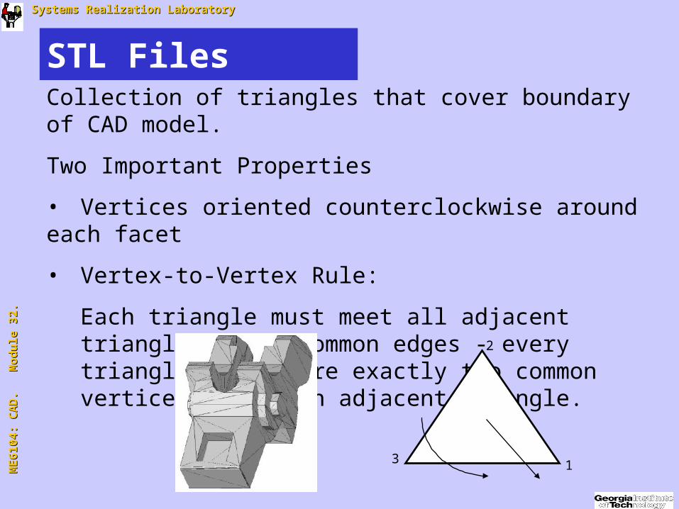
STL FilesCollection of triangles that cover boundary of CAD model.
Two Important Properties
• Vertices oriented counterclockwise around each facet
• Vertex-to-Vertex Rule:
Each triangle must meet all adjacent triangles along common edges - every triangle must share exactly two common vertices with each adjacent triangle.
1
2
3
M
E6
10
4:
CA
D.
M
od
ule
32
. M
E6
10
4:
CA
D.
M
od
ule
32
. Systems Realization LaboratorySystems Realization Laboratory
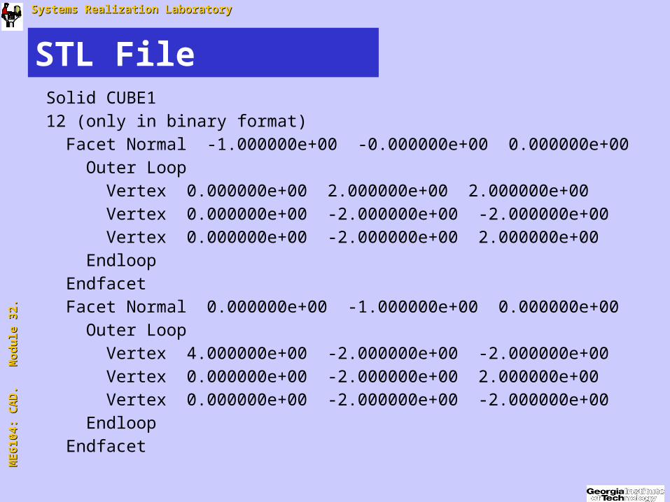
STL FileSolid CUBE112 (only in binary format) Facet Normal -1.000000e+00 -0.000000e+00 0.000000e+00 Outer Loop Vertex 0.000000e+00 2.000000e+00 2.000000e+00 Vertex 0.000000e+00 -2.000000e+00 -2.000000e+00 Vertex 0.000000e+00 -2.000000e+00 2.000000e+00 Endloop Endfacet Facet Normal 0.000000e+00 -1.000000e+00 0.000000e+00 Outer Loop Vertex 4.000000e+00 -2.000000e+00 -2.000000e+00 Vertex 0.000000e+00 -2.000000e+00 2.000000e+00 Vertex 0.000000e+00 -2.000000e+00 -2.000000e+00 Endloop Endfacet

M
E6
10
4:
CA
D.
M
od
ule
32
. M
E6
10
4:
CA
D.
M
od
ule
32
. Systems Realization LaboratorySystems Realization Laboratory
Problems with .STL Files
• Shell Punctures
• Inconsistent Facet Orientations
• Incorrect Facet Normal Vectors
• Degenerate Facets:
• Topological - 2 or 3 coincident vertices in a facet
• Geometric - 3 distinct collinear vertices
• Internal Walls and Structures
From: J Bohn & M Wozny, “A Topology-Based Approach for Shell Closure,” Geometric Modelingfor Product Realization, Eds: P Wilson, M Wozny & M Pratt, Elsevier Science Publishers, 1993.

M
E6
10
4:
CA
D.
M
od
ule
32
. M
E6
10
4:
CA
D.
M
od
ule
32
. Systems Realization LaboratorySystems Realization Laboratory
Shell Punctures
• Holes in part boundary often caused by uneven tessellation of surfaces
• Can cause scan line problems
Stray Scan Vector
M
E6
10
4:
CA
D.
M
od
ule
32
. M
E6
10
4:
CA
D.
M
od
ule
32
. Systems Realization LaboratorySystems Realization Laboratory
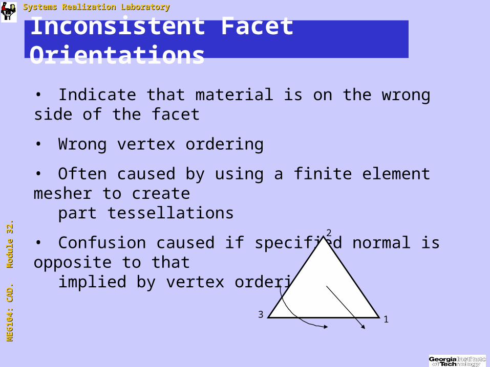
Inconsistent Facet Orientations
• Indicate that material is on the wrong side of the facet
• Wrong vertex ordering
• Often caused by using a finite element mesher to create
part tessellations
• Confusion caused if specified normal is opposite to that implied by vertex ordering
1
2
3
M
E6
10
4:
CA
D.
M
od
ule
32
. M
E6
10
4:
CA
D.
M
od
ule
32
. Systems Realization LaboratorySystems Realization Laboratory
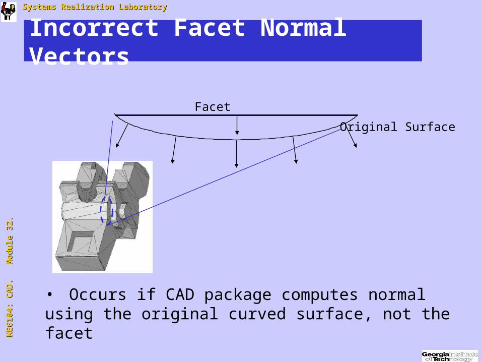
Incorrect Facet Normal Vectors
• Occurs if CAD package computes normal using the original curved surface, not the facet
Facet
Original Surface
M
E6
10
4:
CA
D.
M
od
ule
32
. M
E6
10
4:
CA
D.
M
od
ule
32
. Systems Realization LaboratorySystems Realization Laboratory
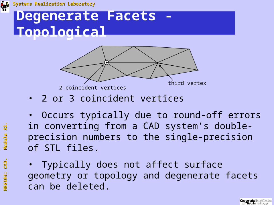
Degenerate Facets - Topological
• 2 or 3 coincident vertices
• Occurs typically due to round-off errors in converting from a CAD system’s double-precision numbers to the single-precision of STL files.
• Typically does not affect surface geometry or topology and degenerate facets can be deleted.
2 coincident verticesthird vertex
M
E6
10
4:
CA
D.
M
od
ule
32
. M
E6
10
4:
CA
D.
M
od
ule
32
. Systems Realization LaboratorySystems Realization Laboratory
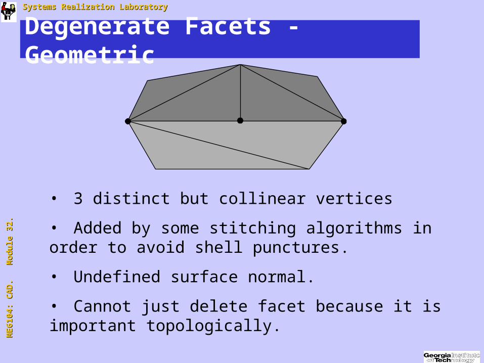
Degenerate Facets - Geometric
• 3 distinct but collinear vertices
• Added by some stitching algorithms in order to avoid shell punctures.
• Undefined surface normal.
• Cannot just delete facet because it is important topologically.

M
E6
10
4:
CA
D.
M
od
ule
32
. M
E6
10
4:
CA
D.
M
od
ule
32
. Systems Realization LaboratorySystems Realization Laboratory
Internal Walls & Structures
• May arise due to designer modeling errors or shortcuts.
Poorly implemented Boolean operations, etc.
=> Non-manifold situations.
• Can cause structural weaknesses (SLS).
Or local shrinkage and part inaccuracies (SLA).
M
E6
10
4:
CA
D.
M
od
ule
32
. M
E6
10
4:
CA
D.
M
od
ule
32
. Systems Realization LaboratorySystems Realization Laboratory
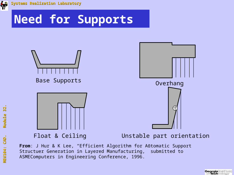
Need for Supports
Base Supports Overhang
Float & Ceiling Unstable part orientation
From: J Hur & K Lee, “Efficient Algorithm for Automatic Support Structuer Generation in Layered Manufacturing,” submitted to ASMEComputers in Engineering Conference, 1996.
M
E6
10
4:
CA
D.
M
od
ule
32
. M
E6
10
4:
CA
D.
M
od
ule
32
. Systems Realization LaboratorySystems Realization Laboratory
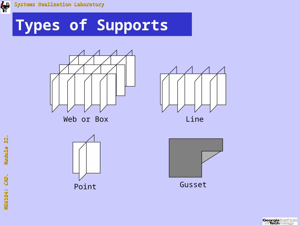
Types of Supports
Web or Box Line
Point Gusset
M
E6
10
4:
CA
D.
M
od
ule
32
. M
E6
10
4:
CA
D.
M
od
ule
32
. Systems Realization LaboratorySystems Realization Laboratory
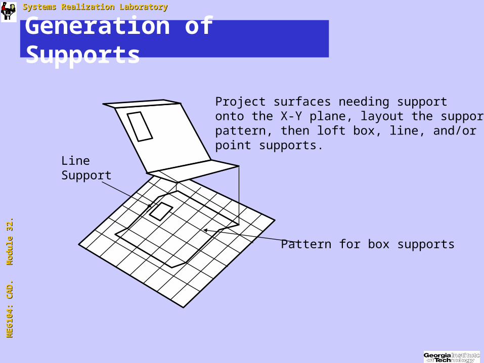
Generation of Supports
LineSupport
Project surfaces needing supportonto the X-Y plane, layout the supportpattern, then loft box, line, and/orpoint supports.
Pattern for box supports

M
E6
10
4:
CA
D.
M
od
ule
32
. M
E6
10
4:
CA
D.
M
od
ule
32
. Systems Realization LaboratorySystems Realization Laboratory
Challenges
• Multiple Materials, Graded Materials
• Many Thousands of Features
• Hierarchical Structures
M
E6
10
4:
CA
D.
M
od
ule
32
. M
E6
10
4:
CA
D.
M
od
ule
32
. Systems Realization LaboratorySystems Realization Laboratory
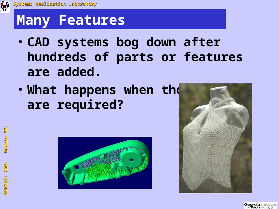
Many Features
• CAD systems bog down after hundreds of parts or features are added.
• What happens when thousands++ are required?
M
E6
10
4:
CA
D.
M
od
ule
32
. M
E6
10
4:
CA
D.
M
od
ule
32
. Systems Realization LaboratorySystems Realization Laboratory
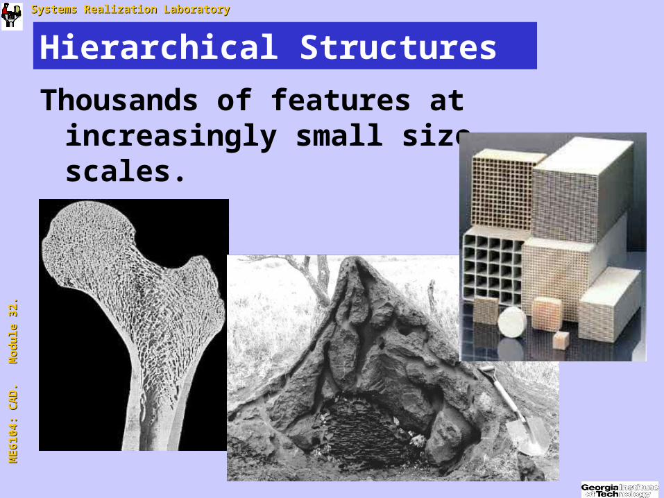
Hierarchical Structures
Thousands of features at increasingly small size scales.
M
E6
10
4:
CA
D.
M
od
ule
32
. M
E6
10
4:
CA
D.
M
od
ule
32
. Systems Realization LaboratorySystems Realization Laboratory
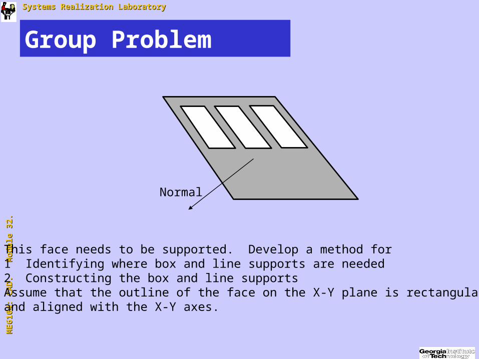
Group Problem
This face needs to be supported. Develop a method for 1 Identifying where box and line supports are needed2 Constructing the box and line supportsAssume that the outline of the face on the X-Y plane is rectangularand aligned with the X-Y axes.
Normal
Related Documents