ME 424 Engineering Design VIII Final Report MATE ROV Underwater Robotics Competition Group ME-07: Stephanie Senkevich Chris Stollen Kevin Grudzinski Advisor: Dr. Frank Fisher “I pledge my honor that I have abided by the Stevens Honor System” Stevens Institute of Technology Castle Point on Hudson MATE ROV – Final Report - Page 1

Welcome message from author
This document is posted to help you gain knowledge. Please leave a comment to let me know what you think about it! Share it to your friends and learn new things together.
Transcript

ME 424 Engineering Design VIII
Final Report
MATE ROV
Underwater Robotics Competition
Group ME-07:
Stephanie Senkevich
Chris Stollen
Kevin Grudzinski
Advisor:
Dr. Frank Fisher
“I pledge my honor that I have abided by the Stevens Honor System”
Stevens Institute of Technology
Castle Point on Hudson
MATE ROV – Final Report - Page 1

Table of Contents Glossary of Terms ......................................................................................................................................... 3
Abstract ......................................................................................................................................................... 4
Introduction.................................................................................................................................................... 5
Competition Background ........................................................................................................................... 5
Competition Overview ............................................................................................................................... 6
Mission Tasks ........................................................................................................................................... 7
Task 1 – Shipwreck ............................................................................................................................... 7
Task 2 – Science ................................................................................................................................... 8
Task 3 - Conservation ........................................................................................................................... 9
Specifications/Constraints ......................................................................................................................... 9
Design ......................................................................................................................................................... 11
1. Chassis ............................................................................................................................................ 11
2. Thrusters ......................................................................................................................................... 12
3. Ballast Control ................................................................................................................................. 14
4. Tether .............................................................................................................................................. 14
5. Actuated Claw ................................................................................................................................. 15
6. Electronics Enclosure ...................................................................................................................... 16
7. Camera Enclosures ......................................................................................................................... 18
8. Camera Software ............................................................................................................................ 19
9. Electronics ....................................................................................................................................... 19
10. Top Side Software & Control ....................................................................................................... 20
11. ROV Side Software ..................................................................................................................... 22
Testing ......................................................................................................................................................... 24
Test #1: ................................................................................................................................................... 24
Test #2: ................................................................................................................................................... 25
Test #3: ................................................................................................................................................... 26
Learning Experiences: ................................................................................................................................ 26
Appendix: .................................................................................................................................................... 27
Final Budget for our Project: ................................................................................................................... 27
Gantt Chart: ............................................................................................................................................. 28
Drawings of Components of ROV: .......................................................................................................... 29
Thruster Test: .......................................................................................................................................... 32
Code of Project:………………………………………………………………………………………………….35
MATE ROV – Final Report - Page 2

Glossary of Terms
● ROV - Remotely Operated Vehicle ● MATE - Marine Advanced Technology Education ● Raspberry Pi - Microcontroller board ● Beaglebone Black - Microcontroller board ● Scuttle - The sinking of a ship ● Bow - The front of a vessel ● Stern - The rear of a vessel ● Heave - The upwards/downwards motion of travel ● Surge - The forwards/backwards motion of travel ● Sway - Forward/backward side-to-side movement ● Yaw - Twisting about the vertical axis ● Roll - Right/left side-to-side movement ● Top-side - System components located above the pool surface ● AWG - Standardized American wire gauge ● DC - Direct Current (Power) ● Bulkhead - The push-pull cable termination end ● IMU - Inertial Measurement Unit
MATE ROV – Final Report - Page 3

Abstract Project Change
Our team initially began as the Autonomous Surface Vehicle (ASV) Roboboat
Competition Team. However, we decided to switch our project to the Marine Advanced Technology Education (MATE) Center’s Remotely Operated Vehicle (ROV) underwater robotics competition. We made this switch because the ASV project had too large a programming aspect for our team of solely mechanical engineers. Previous teams had been interdisciplinary, with electrical and computer engineers on the team. Another factor initiating the change was that the pre-existing boat would require very minimal mechanical engineering input. Lastly, the updated competition rules would not be released until mid to late December so our initial research on the competition was based off of the previous year’s rules. MATE ROV Competition:
The Marine Advanced Technology Education (MATE) Center hosts an annual remotely operated vehicle (ROV) underwater robotics competition. This competition is held at the beginning of May and this year will focus on shipwreck remediation and exploration where remains have fallen to the bottom of the ocean. Over the past two semesters, we have successfully designed, fabricated, and tested an ROV that is capable of exploring and documenting a simulated shipwreck at the bottom of a 20 feet deep pool for the competition. Controlled live by a pilot from ashore, the ROV can navigate through the makeshift shipwreck and also collect microbial samples, test the conductivity of the water, and remove trash and debris from the shipwreck’s surrounding area. The ROV has been designed to be modular, so components can be changed and relocated from year to year. The ROV has also been constructed with a budget substantially less than most other teams. We intend to prove our design at the upcoming competition.
MATE ROV – Final Report - Page 4

Introduction
Our remotely operated vehicle (ROV) will be designed to execute several specific tasks specified by the Marine Advanced Technology Education (MATE) Center for its 2014 MATE ROV competition. The theme of this year’s competition is exploring shipwrecks, investigating sinkholes, and performing conservation tasks in the Thunder Bay National Marine Sanctuary in Lake Huron. Shipwrecks can be very dangerous for humans to explore so robots are necessary to complete the task. These robots can take video footage and survey the area and obtain data for humans to analyze. This design project challenges the team to develop a functioning ROV robot that meets specific requirements set forth by the competition.
The MATE ROV Regional competition will take place on May 10th at Rowan University. If the ROV successfully passes the demonstration and safety check, we will move on to the International Competition, which takes takes place in Alpena, Michigan on June 26-28. There, the team will compete against over 20 other teams.
Throughout the course of the past two semesters our group has remained on task to successfully design, fabricate, and test an operational ROV that fulfills mission requirements. The team has done so with a modular design that can be easily modified for future years and at a budget that is substantially less than the the budgets of most of the other competing teams.We have had the opportunity to test the ROV’s functionality in the water and it has successfully performed. Our current focus is to continue to test and fine tune our ROV to fully prepare it for the Regional Demonstration Day, and then based on feedback there prepare it for the International Competition.
Competition Background The MATE ROV Competition is unique. Focusing on more than just engineering
skills, the MATE ROV Competition challenges teams to think as an entrepreneur, and to develop the ability to understand the breadth of business operations. The MATE ROV Competition is broken into 4 different levels called classes, which are Scout Class, Navigator Class, Ranger Class and Explorer Class. Our team will be competing in the Explorer Class competition, which is designed for university level and experienced high school level teams.
MATE ROV – Final Report - Page 5

Competition Overview The competition involves three mission tasks that are split into three themes:
1. Explore, document, and identify an unknown shipwreck recently discovered in sanctuary waters.
2. Collect microbial samples and measure the conductivity of the groundwater emerging from a sinkhole.
3. Remove trash and debris from the shipwreck and surrounding area.
Teams are given a time limit of 15 minutes to complete all tasks. The competition takes place in a 20 ft. deep indoor pool. No water currents will be intentionally created. The robot must conform to an extensive list of requirements and constraints that are outlined in the competition manual. These specifications involve documentation, safety, mechanical properties, and electrical requirements.
Beyond the main underwater missions, the teams will be scored on a technical
report, an engineering presentation, a poster display, and a safety inspection with the following scoring breakdown, for a total maximum score of 580 points:
● Mission - 300 points ● Written Technical Report - 100 points ● Oral Engineering Evaluation - 100 points ● Poster Display - 50 points ● Safety - 30 points
Figure 1: Picture of a Shipwreck on the ocean floor
MATE ROV – Final Report - Page 6

Mission Tasks The mission consists of 3 tasks that our ROV will need to perform, with a time
limit of 15 minutes. Tasks may be done in any order and teams may switch between tasks freely. Teams may remove the vehicle from the water for troubleshooting, buoyancy adjustments, and payload changes, but the timer will not stop. Teams will receive bonus points for completing all tasks before the mission time ends and penalties for exceeding the given time or leaving debris on the pool bottom. In addition to the mission time, teams are allotted 5 minutes to setup and test the vehicle at the mission station and 5 minutes to break down and exit the mission station. A maximum of two mission attempts will be allowed per team, with the higher scoring attempt used toward the overall score.
Task 1 – Shipwreck
The first task is to explore, document, and identify a newly discovered shipwreck. The ROV will complete several different tasks to piece together the identify of the wreck. Using all of the features, the team will identify the ship from a list of 24 possible wrecks. This first task will involve the following steps:
● The length, width, and height of the shipwreck will be measured. ● The shipwreck will be “scanned” with sonar. This is simulated by taking pictures of the
wreck at three different target locations. The ROV must maintain alignment for five seconds.
● A photomosaic of images taken at five distinct locations will be stitched together.
Figure 2: Simulated shipwreck environment
MATE ROV – Final Report - Page 7

● Visual evidence of a propeller, paddlewheel, or mast head will be found to identify the type of ship. This will allow the team to determine whether the ship was a bulk freighter, a paddle-wheel ship, or a sailing schooner respectively.
● A cargo hatch will be unlocked by turning a PVC handle to open the cargo container. Then, the door of the cargo container must be opened to allow for identification of the cargo. No cargo must be returned to the surface. After identification, the cargo door will be closed and the hatch relocked. The handle and cargo door will take less than 2 newtons to turn and open.
● The ROV will enter a 75 cm X 75 cm hole near the bow of the ship. Debris will be located in front of this hole that the ROV must remove before entering the wreck.
● The date the ship was built will be etched on a 5 cm x 15 cm piece of black plastic. There will be limited visibility inside the shipwreck so a source of light may be required. The date on the video feed must be shown to the judge.
● There will be a plate at the bottom of the ship that has its home port on it. This plate will need to be found and brought back to the surface. There, the crew will remove debris from the plate and identify the home port of the ship.
Task 2 – Science
The second task involves collection of data, collection of a sample of a microbial mat, replacement of a sensor string, and a calculation of the number of mussels on the exterior of the shipwreck. The individual steps of this task are:
● Investigating a sinkhole in the site area and using a conductivity sensor to measure and record the conductivity level of the groundwater that will be overflowing out of the sinkhole. The sensor will have to be inserted into the sinkhole at least 7 cm to get an accurate reading. The sensor may be incorporated into the ROV or be independent of the vehicle.
● Retrieving 150 mL of microbial mat (simulated by plastic cups full of agar) from a cup near the sinkhole and returning it to the surface.
● Returning a sensor string to the surface and replacing it with a new one to the same specific area on the pool floor. Sensor strings will have a 2 lb dive weight attached to its bottom. The strings will weight less than 25 newtons underwater.
● Using a 50 cm x 50 cm quadrat to measure the amount of zebra mussels on the top of the ship. The dimensions of the wreck calculated in task 1 will be used to calculate the overall amount of mussels covering the shipwreck. The bottom surface of the ship does not need to be calculated. Subtraction for the area of the hole does not need to be made.
MATE ROV – Final Report - Page 8

Task 3 - Conservation
This task involves removing debris from the site area. The steps for this task are: ● Removing a capless 1 liter plastic bottle from the pool floor and returning it to the surface ● Removing a capless glass bottle from the pool floor and returning it to the surface ● Removing the anchor line rope debris that blocks the hole in the shipwreck and returning
it to the surface. The debris will weight less than 10 newtons. ● Removing an 8 lb danforth anchor with 1.5 meter long chain attached from the bottom of
the pool and returning it to the surface. The anchor and chain combined will weigh less than 100 newtons underwater.
Specifications/Constraints
The competition manual and rulebook lays out many requirements and constraints that our ROV must satisfy. Combined with the mission requirements, the team identified the core requirements that our ROV must satisfy in order to succeed in the competition. These are the technical requirements that we designed our ROV to meet.
Technical Specification Reasoning/Rule Reference
ROV must grip items ranging in size from ¼” to 2”. Must move dinner plate and PVC pipe to surface
ROV must be able to lift and grip items weighing up to 100N (22.5 lbs)
Max weight of anchor and chain
ROV must be able to hold position for 5 seconds Sonar mission task
ROV must have color camera Required for mission tasks
Electronics housings must be waterproof to 6 meters (20 feet) MECH-001
ROV must have a frontal area less than 75 cm x 75 cm MECH-002: ROV must fit into shipwreck
ROV must weigh less than 75 lbs. out of water MECH-002: Vehicle must be hand launched
Tether length must be at least 20 meters MECH-003
MATE ROV – Final Report - Page 9

All power must be obtained from MATE supply with 40 amp fuse (no onboard batteries)
ELEC-001
ROV system must operate on power supply of up to 56 Volts, with expected nominal voltage of 48 VDC
ELEC-002
Any Supply voltage modification must take place on ROV ELEC-003
No voltage above 48V is permitted anywhere in the ROV system
ELEC-005
Must have 40A fuse or circuit breaker in positive power supply line within 30 cm of attachment point
ELEC-008
Power supply connections must connect via ¼” bolt with wing nut
ELEC-010
All electrical connections must be sealed and not exposed to water
ELEC-016
“Disposable motors” (exposed motors without waterproofing) are not permitted
ELEC-017
ROV must shutdown within 5 seconds of loss of surface power supply
ELEC-019
MATE ROV – Final Report - Page 10

Design The ROV chassis is comprised solely of standard 1 inch diameter PVC pipe and fittings, creating the framework for the fully modular system. All PVC fittings and pipe are primed and glued to prevent any water infiltration. Ballast tanks are comprised of twin 4 inch diameter PVC pipe with dual internal bicycle inner-tubes; the tanks are affixed with acetal polymer U-bolts, easy to remove, corrosion proof and lightweight. All circuitry including the DC-DC step-downs, microprocessors, etc. are encased in a 6 inch diameter acrylic tube. The tether inlet and outlet connections are made through a remote pipe-manifold so as to reduce the chance of flooding. Multiple cameras are individually housed and sealed in 1.5 inch PVC pipe to allow modularity to aid in adjustments. Thrusters are mounted with adjustable mounts capable of incremental angles and heights on any section of the PVC frame. The custom fabricated claw is powered with an actuator remotely through a mechanical control cable. All the ROV electrical wire entrances will be waterproofed using wire-gland seals.
Our ROV is controlled using software on two computers. The Beaglebone Black, a low cost single board computer, is located inside the waterproof enclosure on the ROV. It interfaces with all the sensors and motors and performs all of the control operations necessary to keep the ROV operational. A laptop on the surface provides a graphical user interface (GUI) which the operator uses to control the ROV. This interface shows the camera feeds, the input commands being sent to the ROV, and the sensor feedback from the ROV.
The latest version of all of the code is publicly available on GitHub, at https://github.com/kgrudzin/Stevens-MATE-ROV. A copy of the code at this moment in time can be found in the Appendix as well.
ROV Subsystems:
1. Chassis The chassis was constructed with one (1) 10 foot length of 1 inch PVC pipe, in spec to the attached assembly drawing. To ensure buoyancy force reliability the chassis was glued and tested at depth for an extended period of time. A modular top support bar is used to fixture the top thruster, this is constructed with ‘snap’ connectors and is not permanently affixed or waterproofed. The picture below is representative of chassis shape, however no mounting holes penetrate the real model..
MATE ROV – Final Report - Page 11
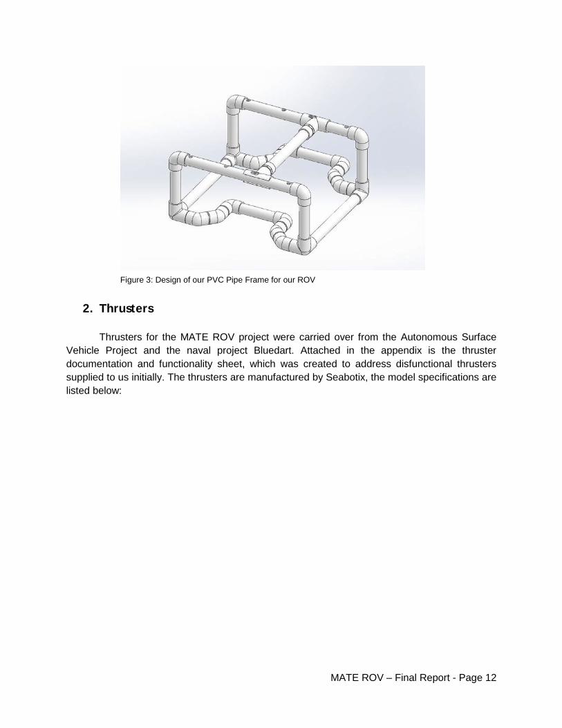
2. Thrusters Thrusters for the MATE ROV project were carried over from the Autonomous Surface Vehicle Project and the naval project Bluedart. Attached in the appendix is the thruster documentation and functionality sheet, which was created to address disfunctional thrusters supplied to us initially. The thrusters are manufactured by Seabotix, the model specifications are listed below:
Figure 3: Design of our PVC Pipe Frame for our ROV
MATE ROV – Final Report - Page 12

Modular thruster mounts consisted of a flat-bar adapter to connect to the thruster, and a round clamp intended to mate to the 1 inch PVC chassis framework. These aluminum mounts were affixed with two (2) ¼-20 x 1.5 inch long stainless steel allen bolts. Engineering drawings for these components are attached in the appendix. This mounting design allowed for full adjustability on the ROV framework, allowing balancing to be conducted between the drag force and thruster force. The thruster configuration is in a vectored format to increase yaw maneuverability and reduce the chances of snagging obstacles.
Figure 4: Picture here is the Seabotix thruster and specifications
Figure 5: Thruster mount with prototype round clamp (in green)
MATE ROV – Final Report - Page 13

3. Ballast Control Neutral buoyancy of the ROV system is achieved with nearly empty ballast inner tubes and permanently affixed foam surrounding the bladders. For heavy lift applications the four (4) 25” inner tubes will be inflated through the tether cable. The inner tube pressure is regulated through a pair of waterproof air actuators, one for venting and another for filling. Variable pressure is kept in the tether supplied by a hand-pump to a maximum pressure of 40 PSI. The standard Schrader valve stems are adapted to the 6mm tubing with modified ⅛ inch NPT to ¼ inch barb adapters. To prevent back-fill of water into the ballast bladders, a miniature 1-way valve is connected inline with the exhaust port. To reduce weight and provide adequate venting the 4 inch PVC ballast tubes are slotted with 0.75 inch wide slots. The entire system is affixed modularly to the frame with 1.25 inch stainless loop clamps and aluminum binding bars. The picture below illustrates this configuration. For engineering drawings of the tube slots and aluminum mounting bar refer to the appendix.
4. Tether The 50 foot long tether is comprised of 4 individual 0.25 inch lines: shielded ethernet, 8 AWG DC ground, 8 AWG DC positive, and 40 PSI air. In order to prevent kinking and knots, the line is affixed together at 12 inch increments over the whole length. These clips (seen below) are 3D printed and removeable in-line, making repairs very simple and fast. The clips fasten tightly to the air line to prevent bunching, while allowing the data and power lines room to independently shift while bending.
Figure 6: Ballast Tank design
MATE ROV – Final Report - Page 14

Tether top-side connections include two (2) ¼ inch lugs to connect to the competition power supply, a 15 amp fuse, and the air hand pump.
5. Actuated Claw The actuated claw is modularly-oriented, designed to adapt to the 1 inch PVC chassis framework. Control of the claw is supplied by a 200 lb capable IP67 rated DC linear actuator as seen below. In order to transfer this power to the claw a high-strength stainless push-pull rod is interfaced between the two component systems. The cable is attached to the actuator through an adaptable clamping system. This system relies on aluminum clamps for strength, and plastic inserts for getting the right contours of the actuator body. In the event of a design change, new clamp inserts can be printed to change the mounting orientation of the actuator.
Figure 7: 3D printed tether clip
Figure 8: Picture and drawing of the Linear actuator
MATE ROV – Final Report - Page 15

On the other end of the push-pull cable is the claw clamping and interfacing manifold, which is positioned to the front and center of the ROV. The claw, originally intended to operate on a parallel jaw design, has one fixed lower jaw and a moving upper jaw. The upper jaw operates as a complex 4-bar linkage, providing a motion pattern to assist the collection of debris. Upon closing, the upper jaw lowers and ‘pulls-in’ towards the lower fixed jaw, making the ROV’s location less critical. In the event that a more effective jaw design is created the jaws are replaceable, through 3D printing, laser cutting, or machining. To affix the push-pull rod to the gripper mount the cable’s bulkhead is clamped with six (6) set screws. The jaw design is shown below, engineering drawings can be found in the appendix.
Figure 9: CAD picture of the functioning claw design grabbing a water bottle
Limitations to the jaw in early testing are caused by the stainless high-strength push-pull rod. The minimum bending radius of the thick cable is very large, and prevents easy mounting on board the ROV frame. Both cable bulkhead mounts are very robust however, so severe bending stress is unforeseeable.
6. Electronics Enclosure Upon attaching to the ROV frame, the tether package is affixed in two (2) locations to avoid excessive strain. Primary wire inputs and outputs are routed through an eight (8) port pipe manifold, consisting of ⅜ and 2¼ NPT fittings. This pipe manifold is routed directly into the electronics enclosure through a 2¼ flexible line. The port usage is listed below:
1. DC ground 2. DC positive 3. Shielded Ethernet
MATE ROV – Final Report - Page 16

4. Thruster 1 5. Thruster 2 6. Thruster 3 7. DC claw actuator 8. Air actuator cable 9. ⅜ NPT SPARE
Permanent connections are made through a 1 inch NPT potted PVC fitting. These connections include the three Raspberry PI cameras and the potted IMU chip. The potting compound utilized for sealing was two part Urethane. While using the pipe-manifold reduces the chances of leaking water coming into direct contact with critical electronics, the non-permanent IP67 wire glands are not guaranteed seals and leaks are common. Upon further testing the wire glands will be sealed from underneath with silicone for a semi-permanent solution. The 6 inch acrylic tube was sealed with identical custom delrin end-caps, one modified to accept the wire inputs. To guarantee a waterproof seal two (2) O-rings were used on each end-cap. The electronic enclosure model can be seen below.
Figure 10: Picture of our electronics enclosure made from 6 inch acrylic tube with all the electronics neatly mounted inside the tube
Internal components were modeled in order to reach a high density pack arrangement. Extra space was allotted for the Beaglebone black for control cables, and the slack cable present upon closing the tube. Small details include custom length stand-offs, a tray-sliding mount, finger-pull hole in front, and the Stevens Institute name on the secondary voltage step-down insert. Additional holes and slots were included to zip-tie loose cables and add snap-fit inserts such as the secondary step-down tray. The electronics tray laser-cut profile with wire-management holes can be seen below.
MATE ROV – Final Report - Page 17

7. Camera Enclosures There are three (3) onboard color cameras onboard the ROV. These cameras cover the front view, left side view, and claw view. Standard Raspberry Pi cameras are utilized, sealed inside 1.25 inch PVC piping. In order to create a clear viewing window, ¼ inch acrylic sheet was laser cut to size and screwed to a modified PVC mounting flange with eight (8) ¼-20 bolts. To provide a wide range of modular adjustability, a singular silicone loop clamp was used with a custom aluminum camera tube adapter to allow for a wide range of motion. This allows tilting, sliding, pivoting, and turning of the lens on the chassis framework to adjust to nearly any desired viewing angle. The silicone cushioning prevents undesired movement, while adding dampening against shocks.
Figure 11: The electronics tray laser-cut profile with wire-management holes
MATE ROV – Final Report - Page 18

Figure 12: Camera enclosure with mount
To extend the camera data cables a ribbon cable kit was purchased. The camera
lengths included two (2) at 30 inches and one (1) at 18 inches. To seal the assemblies, a slit was cut in the endcap of the camera tube to allow the data cable through. This was then sealed with epoxy on the exterior followed by a generous amount of silicone on the inside. With this configuration the cameras should have a considerable working depth, approximately 100 feet. Data control cables are taped down and organized together to prevent snagging and abrasion.
8. Camera Software
The camera system is composed of three Raspberry Pi single board computers with accompanying Raspberry Pi camera modules. Each Pi is running the RPI Cam Web Interface, which provides a web interface for the Raspberry Pi camera. The interface can be viewed in any web browser, and has a live video feed with low latency and high frame rate. Camera settings such as brightness and contrast can be controlled as well. Finally, the interface allows full-HD video or full-res pictures to be recorded on the Pi while the live feed continues. The interface loads automatically when the Pi starts More information and source code for the RPi Cam Web Interface can be found at http://www.raspberrypi.org/forums/viewtopic.php?t=63276 and https://github.com/silvanmelchior/RPi_Cam_Web_Interface
9. Electronics
The electronics used to power and control the ROV and their connections are shown in the figure below. The main power from the tether is split to two main DC/DC converters to drop the supplied 48V down to 20V for the thrusters. These thrusters are controlled by 2 Sabertooth 2x12 motor controllers. The 4th channel on the motor controllers is used to control the linear actuator that moves the claw.
MATE ROV – Final Report - Page 19

We used many small adjustable DC/DC converters to step down the 20V to the 5V needed by the Raspberry Pi’s. One is also used to give 9V to the network switch, and one more provides 12V for the solenoid air valves. The Beaglebone controls everything over various interfaces. The motor controllers are connected over serial, the pressure sensor and IMU are connected over I2C, and the air valves are connected via GPIO pins, with a custom made MOSFET to provide the needed power.
During testing, one issue we had was electronic noise from the motor controllers corrupting the sensor readings. To reduce this problem, we attached a ferrite bead around the sensor wire. This drastically reduced the problems we had reading the sensor.
A network switch connects the Beaglebone and the Raspberry Pi’s to the surface.
Figure 13: Electronics Layout
10. Top Side Software & Control The ROV is controlled via a joystick connected to a laptop on the surface. A GUI displays input commands, sensor readings, and a high resolution real time video feed to the operator. The interface is written in Python using the Pygame library. The Pygame library allows access to the joystick as well as drawing to the screen. Python was chosen because it allows rapid development of the code and has a multitude of libraries
MATE ROV – Final Report - Page 20

that make multi threading and networking straightforward.
The GUI is shown in the figure below. The right side shows the high resolution video feed from the main camera to the operator. Additional video feeds showing the claw and side view are displayed separately on a secondary monitor. The bar on the left displays the status of the system and the commands being sent to the ROV. Pressure and temperature readings, the status of the air valves, and the current status of the claw are displayed in text format. Below that, an artificial horizon and compass display the orientation of the ROV based on the IMU sensor readings. On the bottom, the current speed of the thrusters is displayed.
Figure 14: Pictured above is the GUI. It shows the video feed, status of the systems and the commands being sent to the ROV
The application communicates to the ROV over an Ethernet cable which is part of the tether. Ethernet cable has a maximum recommended run length of 100m, which is well above the length of the tether. With a maximum data speed of 100 Mbps, a single cable has enough data capacity to handle the control data and video feeds.
Data communication is done via the UDP protocol. This was chosen over TCP because we do not need to resend any lost packets as it makes more sense to just send a new packet with updated data. Control packets are sent approximately 100 times per second, making the ROV extremely responsive. The commands are encoded in JSON format, a lightweight data-interchange format that is easy for humans to read and easy for computers to parse. It results in more data being sent, but allows the format of the commands to be changed or new ones to be added with ease. It is also
MATE ROV – Final Report - Page 21
language independent, so if the software on the ROV or surface was rewritten in a different programming language, the commands could easy be parsed and integrated into the new software.
The software has the functionality to save images from the video feed. This is required for the photomosaic stitching task. Since the stitching is required to be done during the timed mission run, an auxiliary laptop will likely be used to process the images into a photomosaic. A free plugin for the free GIMP image editing tool exists that will be used to create the photomosaic.
11. ROV Side Software
The Beaglebone Black (BBB) located on the ROV interfaces directly with all of the electronics via general purpose input output (GPIO) pins, like a microcontroller. The BBB receives control commands sent from the surface. It then uses those command to send appropriate commands to the motor controllers and air valves.
For safety, the system has a watchdog timer. If no control input is received from the surface computer for over a second, the ROV automatically enters a safe state with all of the thrusters off. Normal operation resumes when the control signal is again received.
Reading the IMU data and turning it into a useful representation is rather complex, luckily an open source library is available at https://github.com/mlaurijsse/linux-mpu9150/. Code for the pressure sensor was mostly written in house, with some code used from an Arduino library for the sensor. To access the sensors in Python, custom Python C extension modules were written to bridge the gap between Python and C.
For tasks such as performing a simulated sonar scan and picking up objects, the ROV will need to maintain its depth. To make this as easy as possible for the operator, we would like to use a feedback system that allows us to set a depth and will keep the ROV at that depth. Using feedback from a pressure sensor on the ROV, a PID control algorithm will adjust the vertical thruster speed to hold the ROV at a given depth.
MATE ROV – Final Report - Page 22

Figure 15: Shown above is the Hardware and Software Flowchart
MATE ROV – Final Report - Page 23

Testing
Test #1:
Our first test took place in the Davidson Tank. Our goal was to test the water proofing concept of our ROV. The total depth of the Davidson Tank is 7 feet, which is a big difference from the total depth of our competition. Our testing method was to put several components of the ROV under the water for various increments to constantly check for any water leakage. The first component we tested was our ROV frame. We added weight to the frame to make sure it would sit at the bottom of the tank floor. To properly test it we added weight on the frame to make sure it would sit on the tank floor for the duration of the test. We placed in it for 10 minutes, then 20 minutes and finally 30 minutes. The total length of the competition will be a maximum of 20 minutes. The below figure is a picture of the frame under water. At the end of our test, there was no water in the frame.
We also then tested the water proof capability of our electronic enclosure, pictured below. We placed pieces of paper inside the container to make sure they remained dry during the test. We added weight to this to make sure it sat at on the tank floor. We tested it in various increments of 10 minutes, 20 minutes and 30 minutes. At the end of our test, no water was inside the container and the paper remained dry.
Figure 16: Picture of our ROV frame during water proof testing on the floor of the Davidson Laboratory Tank
Figure 17: Picture of the electronics enclosure being water proof tested
MATE ROV – Final Report - Page 24

Lastly we tested our thrusters to make sure they were functioning. In the end we had 3 working thrusters for our ROV and 1 spare working thruster.
Test #2:
Test #2 took place in Davidson Tanks. The objective was to test the functionality of our ROV. We were focusing on buoyancy and center of gravity and how we could manipulate that by adding, distributing or removing weights onto the ROV. To fully stabilize our ROV we needed to add weight to the left back corner of the ROV. To assist the ROV when sinking or rising in the water, the ballast tanks were filled or depleted. This test proved that the ROV was able to function in all needed directions.
Figure 18: Testing the thrusters to make sure they work
Figure 19: Our ROV functioning in the water
MATE ROV – Final Report - Page 25

Test #3:
Test #3 took place in Davidson Labs, to test the full functioning capability of the ROV with the claw and gripper mechanism. The ROV was able to perform and successfully picked up a water bottle on the bottom of the tank. During the competition our ROV will be performing tasks and the maximum weight our gripper will have to be able to hold is 100N of force which is about 22 lbs. This test also demonstrated the importance of camera placement. Our ROV has 3 cameras strategically placed on the ROV so that we can see any view we need to. This test demonstrated that our depth perception through our camera were accurate when we were successfully able to pick up the water bottle.
Learning Experiences: To be successful on any major project, especially design projects, team work is definitely the most important aspect. Every member of the team plays a special role and it requires hard work and dedication. Communication amongst group members should be done often to make sure everyone is on the same page. To help remain on task throughout the duration of the project, the Gantt Chart is very beneficial and is a valuable asset that is under used in industry. If given this opportunity again, it would be in the student’s best interest to seek advice from multiple people, not just from each other and the advisor. Our group started to reach out to various departments and students but would recommend other groups do it before designing the ROV so that their input can have a stronger effect on the outcome of the project. Testing is also very important. Testing is where the group has hands on experience to correct and improve the project. Our group had the opportunity to test different components individually and also as one unit. We were successful and satisfied with our testing procedures but you can never have enough testing. Testing, especially for an ROV gives students the opportunity to see what could go wrong during a competition and how to be able to quickly adjust and fix the ROV so that in the competition environment students will remain calm to fix the problem and finish the competition.
Figure 20: Set up before testing Figure 21: ROV grabbing a water bottle on the tank floor
MATE ROV – Final Report - Page 26

Appendix:
Final Budget for our Project:
The figure above shows the total budget for our project. Buying every part new and at full value our project would have been about $3,374.50. Thankfully we were able to get a student credit discount from Misumi and we already had our Seabotix Thruster from previous
Appendix 1: Our final Budget for our Project
MATE ROV – Final Report - Page 27

years. With this help our budget only equaled $972.42. This project is unique because we are able to build a whole functioning underwater ROV for a fairly cheap cost considering other projects and their functions and costs.
Gantt Chart: Pictured above is our team’s Gantt Chart. Throughout the course of the semester tasks were modified to keep with the needs of our project. This work break down scheduled help to keep our group focused and organized on completing each phase of our project and keep a good pace to make sure we allowed for adequate testing of our project in water to make sure it was ready for competition.
Appendix 2: Final Gantt Chart of our Project over the course of 2 semesters, condensed for easy visibility
MATE ROV – Final Report - Page 28

Drawings of Components of the ROV:
MATE ROV – Final Report - Page 29

MATE ROV – Final Report - Page 30

MATE ROV – Final Report - Page 31

Thruster Test:
MATE ROV – Final Report - Page 32

Code: The entire project code can be seen over the next few pages
MATE ROV – Final Report - Page 33

MATE ROV – Final Report - Page 34

MATE ROV – Final Report - Page 35

MATE ROV – Final Report - Page 36
MATE ROV – Final Report - Page 37

MATE ROV – Final Report - Page 38

MATE ROV – Final Report - Page 39

MATE ROV – Final Report - Page 40

MATE ROV – Final Report - Page 41

MATE ROV – Final Report - Page 42

MATE ROV – Final Report - Page 43

MATE ROV – Final Report - Page 44

MATE ROV – Final Report - Page 45

MATE ROV – Final Report - Page 46

MATE ROV – Final Report - Page 47

MATE ROV – Final Report - Page 48

MATE ROV – Final Report - Page 49

MATE ROV – Final Report - Page 50

MATE ROV – Final Report - Page 51

MATE ROV – Final Report - Page 52
Related Documents