ME 24-688 – Week 11 Windshield Wiper Assembly ME 24-688 – Introduction to CAD/CAE Tools Page 1 of 58 aWindshield Wiper Assembly Within this project there are three separate projects that all work on completing dynamic simulation activities on a windshield wiper assembly. The project will cover creating and editing joints plus assigning loads. The Output Grapher will also be used in each project to analysis and view key critical data on the performance of the design. 1.1 Project 3A – Joint Properties and Defining Loads In this project you create joints in a wiper assembly to drive the wiper arms. You impose motion on the drive arm and add resistive force to the wiper blades to simulate the friction of the blade on the windshield. Finally you use the Input Grapher to define the resistive force so that it is always opposed to the wiper motion.

Welcome message from author
This document is posted to help you gain knowledge. Please leave a comment to let me know what you think about it! Share it to your friends and learn new things together.
Transcript

ME 24-688 – Week 11
Windshield Wiper Assembly
ME 24-688 – Introduction to CAD/CAE Tools Page 1 of 58
aWindshield Wiper Assembly
Within this project there are three separate projects that all work on completing dynamic simulation
activities on a windshield wiper assembly. The project will cover creating and editing joints plus assigning
loads. The Output Grapher will also be used in each project to analysis and view key critical data on the
performance of the design.
1.1 Project 3A – Joint Properties and Defining Loads
In this project you create joints in a wiper assembly to drive the wiper arms. You impose motion on the
drive arm and add resistive force to the wiper blades to simulate the friction of the blade on the
windshield. Finally you use the Input Grapher to define the resistive force so that it is always opposed to
the wiper motion.

ME 24-688 – Week 11
Windshield Wiper Assembly
ME 24-688 – Introduction to CAD/CAE Tools Page 2 of 58
1. In this section of the project, you define the joints that connect the drive arm to the cranks that
move the wiper subassemblies. Open the WiperAssemblyDEC.iam Autodesk Inventor assembly
file.
2. Click Environments tab | Begin panel | Dynamic Simulation.
3. If required, click No to close the message window for viewing the standard tutorial.
4. The model already has some setup items completed and joints created as a starting point for this
project. On the ViewCube, click the top-right corner.
5. Review the assembly as shown below. The simulation requires a joint to control the rotation of
the Motor_Crank_Asm (1). This subassembly is attached to the wiper motor and drives the
Crank_motor2 component (2), which drives the wiper subassemblies (3).

ME 24-688 – Week 11
Windshield Wiper Assembly
ME 24-688 – Introduction to CAD/CAE Tools Page 3 of 58
6. On the Joint panel, click Insert Joint to start the process for creating a new mechanical joint.
7. Select Cylindrical from the list. The Cylindrical joint has two (2) DOF one rotation and one
translation.
8. For the Component 1 Z Axis select the hole of the Motor_Crank_Asm as shown.

ME 24-688 – Week 11
Windshield Wiper Assembly
ME 24-688 – Introduction to CAD/CAE Tools Page 4 of 58
9. In the Insert Joint dialog box, under Component 2, click the second selection button.
10. Select the work axis, as shown.
11. Click OK. The cylindrical joint enables the Motor_Crank_Asm to rotate freely around the work
axis and move along the work axis.
ME 24-688 – Week 11
Windshield Wiper Assembly
ME 24-688 – Introduction to CAD/CAE Tools Page 5 of 58
12. On the Joint panel, click Insert Joint to start creating another joint.
13. Select Revolution from the list of joint types. This revolution joint will have one rotation DOF
around the Z Axis.
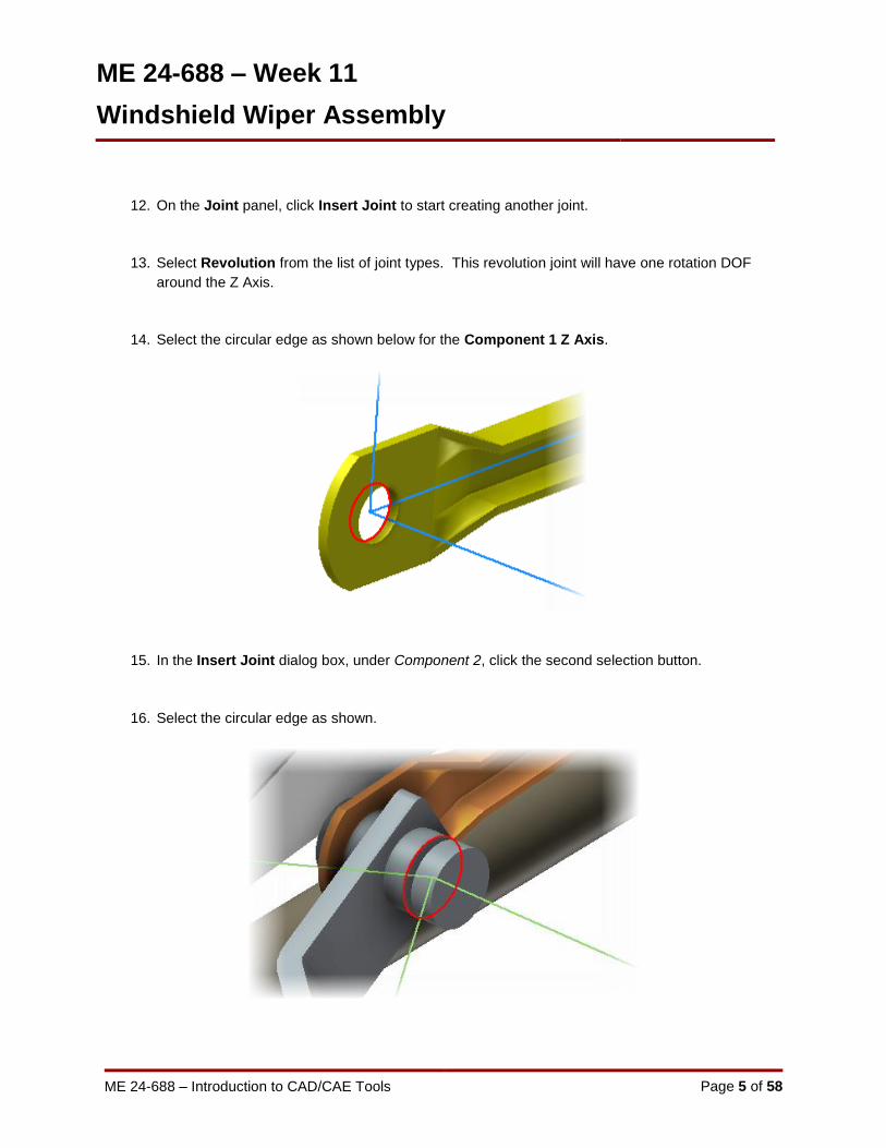
14. Select the circular edge as shown below for the Component 1 Z Axis.
15. In the Insert Joint dialog box, under Component 2, click the second selection button.
16. Select the circular edge as shown.

ME 24-688 – Week 11
Windshield Wiper Assembly
ME 24-688 – Introduction to CAD/CAE Tools Page 6 of 58
17. Under Component 2, click Flip X Axis Direction as shown, to reverse the direction of the X Axis.
This will more closely align the two components in place.
18. Click Apply. The Crank_motor2 moves to the correct position. The Insert Joint dialog box
remains open.

ME 24-688 – Week 11
Windshield Wiper Assembly
ME 24-688 – Introduction to CAD/CAE Tools Page 7 of 58
19. In the Insert Joint dialog box, select Spherical from the list. This joint will have three (3) DOF all
rotational about a point. This type of joint is used to not over constrain the component.
20. Select the circular edge as shown.
21. In the Insert Joint dialog box, under Component 2, click the second selection button.
22. Select the circular edge as shown.

ME 24-688 – Week 11
Windshield Wiper Assembly
ME 24-688 – Introduction to CAD/CAE Tools Page 8 of 58
23. Review the alignment of the coordinate axes. The Z axis (1) of component 1 is pointing in the
opposite direction of the Z axis (2) of component 2.
24: Under Component 2, click Flip Z Axis Direction as shown to reverse the direction of the Z axis.
ME 24-688 – Week 11
Windshield Wiper Assembly
ME 24-688 – Introduction to CAD/CAE Tools Page 9 of 58
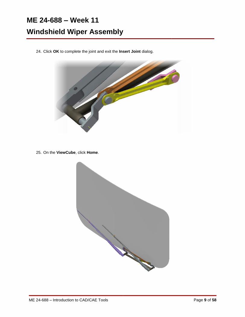
24. Click OK to complete the joint and exit the Insert Joint dialog.
25. On the ViewCube, click Home.

ME 24-688 – Week 11
Windshield Wiper Assembly
ME 24-688 – Introduction to CAD/CAE Tools Page 10 of 58
26. Save the assembly file.
27. In this section of the project, you impose motion on the Motor_Crank_Asm to simulate the wiper
motor driving the wipers. Then you add a resistant force to the wipers to simulate the wiper blade
rubbing against the windshield as it turns.
Zoom in on the assembly as shown.
28. In the Browser, right-click Cylindrical:5 (Motor_Crank_Asm:1, Bearings:1). Click Properties.

ME 24-688 – Week 11
Windshield Wiper Assembly
ME 24-688 – Introduction to CAD/CAE Tools Page 11 of 58
29. On the dof 1 (R) tab, do the following:
Confirm that Edit Initial Conditions is selected. This will specify the starting position of the
components.
For Position, enter -15 deg
Click OK
30. On the ViewCube, click Front. Zoom in to the coordinate system axes.
31. Review the axes. The -15 deg angle is placed between the X axis of component 1 in the
cylindrical joint and the X axis of component 2. This is now the initial starting position for the
simulation.

ME 24-688 – Week 11
Windshield Wiper Assembly
ME 24-688 – Introduction to CAD/CAE Tools Page 12 of 58
32. On the ViewCube, click Home.
33. In the Browser, right-click Cylindrical:5 (Motor_Crank_Asm:1, Bearings:1). Click Properties.
34. On the dof 1 (R) tab, do the following:
Click Edit Imposed Motion
Select the Enable Imposed Motion check box
Under Driving, select Velocity
Click the Arrow. Select Constant Value
Enter 180 deg/s
Click OK
This will set the constraint to rotate about the Z axis 180 degree per each second of the
simulation.

ME 24-688 – Week 11
Windshield Wiper Assembly
ME 24-688 – Introduction to CAD/CAE Tools Page 13 of 58
35. In the Simulation Player, do the following:
In the Final Time window, enter 4 s. This simulates two full revolutions.
Press TAB. In Images, the value should change to 400 to capture 400 frames during the
simulation.
Click Run or Replay the Simulation.
With the simulation set to four seconds the Motor_Crank_Asm component will make two
complete revolutions.
36. In the Simulation Player, click Construction Mode.
37. Zoom in on the assembly as shown.

ME 24-688 – Week 11
Windshield Wiper Assembly
ME 24-688 – Introduction to CAD/CAE Tools Page 14 of 58
38. Save your Assembly file.
39. On the Load panel, click Force.
40. Select the work point on the wiper blade, as shown.
41. Select the flat face of the wiper arm, as shown.

ME 24-688 – Week 11
Windshield Wiper Assembly
ME 24-688 – Introduction to CAD/CAE Tools Page 15 of 58
42. In the Force dialog box, do the following:
For Magnitude, enter 5 N.
Click Associative Load Direction. This option causes the force to maintain its relationship to
the location point.
Click the << More button
Select the Display check box. This displays the force direction when you run a simulation.
Click OK.
43. Review the browser. The Force is added beneath the External Loads node.

ME 24-688 – Week 11
Windshield Wiper Assembly
ME 24-688 – Introduction to CAD/CAE Tools Page 16 of 58
44. Save the assembly file.
45. In the Simulation Player, click Run or Replay the Simulation. The force arrow is displayed on
the wiper blade during the simulation, as shown.
The resistive force maintains the same direction on the wiper throughout the simulation. The
resistive force of the wiper should always be opposite to the motion. You use the Input Grapher
to change the direction of the force when the wiper changes direction.
46. In the Simulation Player, click Construction Mode.
47. In the Browser, right-click Force1 (Force on Brush:1). Click Edit.
48. In the Force dialog box, click the Arrow in the Magnitude edit box. Click Input Grapher.

ME 24-688 – Week 11
Windshield Wiper Assembly
ME 24-688 – Introduction to CAD/CAE Tools Page 17 of 58
49. In the Magnitude dialog box, click Select Reference.
50. In the Select Reference dialog box, do the following:
Expand Standard Joints
Expand Revolution:1 (Bearings:1, Welded group1)
Expand Velocities
Select the V[1] check box
Click OK

ME 24-688 – Week 11
Windshield Wiper Assembly
ME 24-688 – Introduction to CAD/CAE Tools Page 18 of 58
51. In the Magnitude dialog box, under Starting Point, do the following:
For X1, enter -1 deg/s.
For Y1, enter 5 N.
For X2, enter 1 deg/s.
For Y2, enter -5 N.
Between -1 deg/s velocity and 1 deg/s velocity, the resistant force reverses itself, avoiding a
discontinuity or immediate switch in the resistive force.
52. In the Magnitude dialog box, the graph is updated to reflect the values in the Starting Point and
Ending Point areas. The ramp area is shaded in the graph.
To create a smooth transition in the resistive force, you can change the ramp from a linear ramp
to a cubic ramp.
ME 24-688 – Week 11
Windshield Wiper Assembly
ME 24-688 – Introduction to CAD/CAE Tools Page 19 of 58
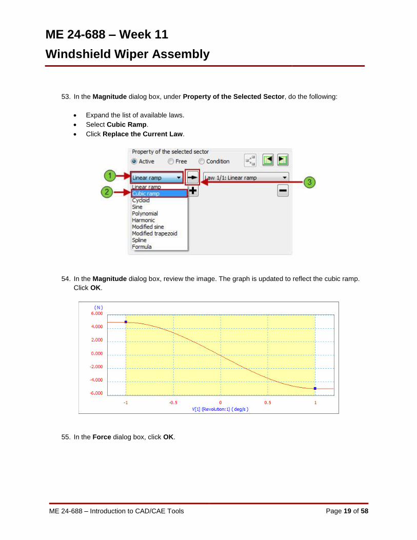
53. In the Magnitude dialog box, under Property of the Selected Sector, do the following:
Expand the list of available laws.
Select Cubic Ramp.
Click Replace the Current Law.
54. In the Magnitude dialog box, review the image. The graph is updated to reflect the cubic ramp.
Click OK.
55. In the Force dialog box, click OK.

ME 24-688 – Week 11
Windshield Wiper Assembly
ME 24-688 – Introduction to CAD/CAE Tools Page 20 of 58
56. In the Simulation Player, click Run or Replay the Simulation. The resistive force arrow
direction reverses when the wiper reverses, as shown.
Because both wiper blades rub against the windshield, you need to repeat steps 39 through 56
for the other wiper. This is optional at this time and would be required to have a better simulation.
57. Save and close the file so you can review the simulation later if required.

ME 24-688 – Week 11
Windshield Wiper Assembly
ME 24-688 – Introduction to CAD/CAE Tools Page 21 of 58
1.2 Project 3B – Calculate the Drive Torque of the Wiper Assembly
Use Dynamic Simulation on the wiper assembly to calculate the driving torque required to move the
wipers so that you can size the wiper motor. You then use the Output Grapher to plot the graph and
review the results.

ME 24-688 – Week 11
Windshield Wiper Assembly
ME 24-688 – Introduction to CAD/CAE Tools Page 22 of 58
1. Open WiperAssemblySDP.iam Autodesk Inventor assembly file as shown below.
2. Click Environments tab | Begin panel | Dynamic Simulation.
3. If you are prompted to view the tutorial, click No to close the window.
4. On the Manage panel, click Simulation Settings.
ME 24-688 – Week 11
Windshield Wiper Assembly
ME 24-688 – Introduction to CAD/CAE Tools Page 23 of 58
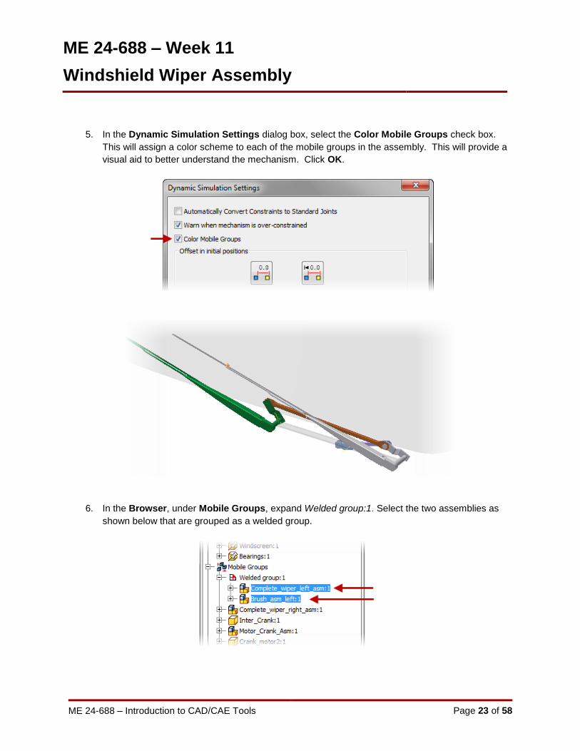
5. In the Dynamic Simulation Settings dialog box, select the Color Mobile Groups check box.
This will assign a color scheme to each of the mobile groups in the assembly. This will provide a
visual aid to better understand the mechanism. Click OK.
6. In the Browser, under Mobile Groups, expand Welded group:1. Select the two assemblies as
shown below that are grouped as a welded group.
ME 24-688 – Week 11
Windshield Wiper Assembly
ME 24-688 – Introduction to CAD/CAE Tools Page 24 of 58
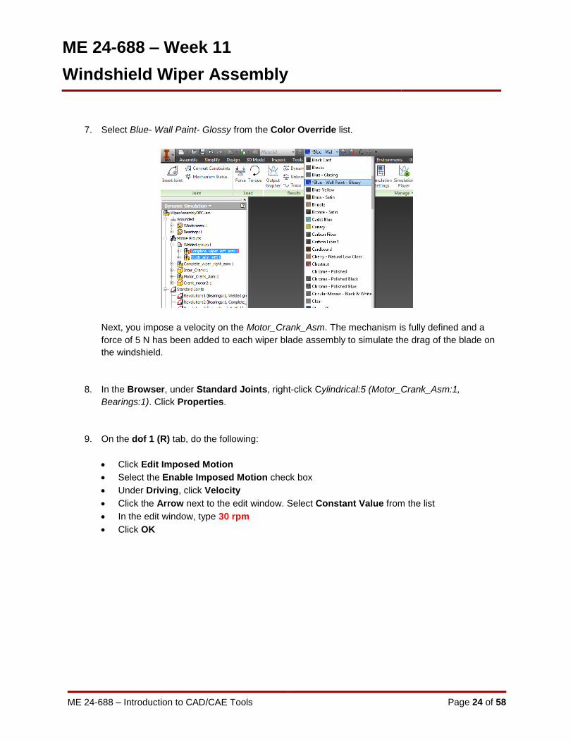
7. Select Blue- Wall Paint- Glossy from the Color Override list.
Next, you impose a velocity on the Motor_Crank_Asm. The mechanism is fully defined and a
force of 5 N has been added to each wiper blade assembly to simulate the drag of the blade on
the windshield.
8. In the Browser, under Standard Joints, right-click Cylindrical:5 (Motor_Crank_Asm:1,
Bearings:1). Click Properties.
9. On the dof 1 (R) tab, do the following:
Click Edit Imposed Motion
Select the Enable Imposed Motion check box
Under Driving, click Velocity
Click the Arrow next to the edit window. Select Constant Value from the list
In the edit window, type 30 rpm
Click OK

ME 24-688 – Week 11
Windshield Wiper Assembly
ME 24-688 – Introduction to CAD/CAE Tools Page 25 of 58
10. In the Simulation Player, do the following:
For Final Time, type 2 s.
Press TAB on the keyboard. The Images value changes to 200.
Click Run or Replay the Simulation.
11. On the Results panel, click Output Grapher.

ME 24-688 – Week 11
Windshield Wiper Assembly
ME 24-688 – Introduction to CAD/CAE Tools Page 26 of 58
12. In the Values window, right-click in the U_imposed column. Click Search Max.

ME 24-688 – Week 11
Windshield Wiper Assembly
ME 24-688 – Introduction to CAD/CAE Tools Page 27 of 58
13. Review the grapher. From the results you can determine the following:
In the Values window, the maximum driving torque of 4148 N mm is highlighted.
In the graph, the time bar displays the corresponding time.
The assembly is synchronized to the grapher, and the mechanism shows the position of the
wipers at maximum drive torque.
14. On the Output Grapher toolbar, click Save Simulation.
15. For file name, type Simulation_01. Click Save. This will save the current results to an external
file that can later be imported back into the Output Grapher.

ME 24-688 – Week 11
Windshield Wiper Assembly
ME 24-688 – Introduction to CAD/CAE Tools Page 28 of 58
16. On the Simulation Player, click Construction Mode.
17. In the Dynamic Simulation browser, under Standard Joints, right-click Cylindrical:5
(Motor_Crank_Asm:1, Bearings:1). Click Properties.
18. For velocity, type 360 deg/s which is 60 rpm then click OK.
19. In the Simulation Player, click Run or Replay the Simulation.
20. Right-click in the U_imposed[1] column. Click Curve Properties.
21. Change color to Red. Click OK twice.

ME 24-688 – Week 11
Windshield Wiper Assembly
ME 24-688 – Introduction to CAD/CAE Tools Page 29 of 58
22. The new graph in the Output Grapher should look like the image below.
23. On the Output Grapher toolbar, click Import Simulation.
24. Open Simulation_01.iaa file you saved earlier in the project.
25. In the Output Grapher browser, expand Simulation_01.iaa | Cylindrical:5 (Motor_Crank_Asm:1,
Bearings:1).

ME 24-688 – Week 11
Windshield Wiper Assembly
ME 24-688 – Introduction to CAD/CAE Tools Page 30 of 58
26. Under Driving Force, select the U_imposed[1] check box.
27. Review the two graphs.

ME 24-688 – Week 11
Windshield Wiper Assembly
ME 24-688 – Introduction to CAD/CAE Tools Page 31 of 58
28. On the Output Grapher toolbar, click Add Trace. You can also start the Trace command from
the Results panel of the ribbon menu.
29. Select the Velocity Display Trace check box.
30. Select the point on the end of the wiper as shown then click Apply.

ME 24-688 – Week 11
Windshield Wiper Assembly
ME 24-688 – Introduction to CAD/CAE Tools Page 32 of 58
31. Select Velocity and then select the point at the opposite end of the wiper as shown then click
OK.
32. On the ViewCube, click Home.
33. In the Simulation Player, click Rewind to the Beginning of the Simulation.
ME 24-688 – Week 11
Windshield Wiper Assembly
ME 24-688 – Introduction to CAD/CAE Tools Page 33 of 58
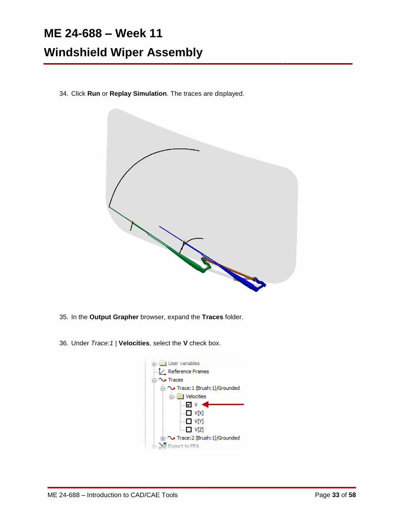
34. Click Run or Replay Simulation. The traces are displayed.
35. In the Output Grapher browser, expand the Traces folder.
36. Under Trace:1 | Velocities, select the V check box.

ME 24-688 – Week 11
Windshield Wiper Assembly
ME 24-688 – Introduction to CAD/CAE Tools Page 34 of 58
37. Review the graphs. The velocity of the point selected for the trace is displayed with the previous
graphs.
38. Save the file so you can review the results as required.
ME 24-688 – Week 11
Windshield Wiper Assembly
ME 24-688 – Introduction to CAD/CAE Tools Page 35 of 58
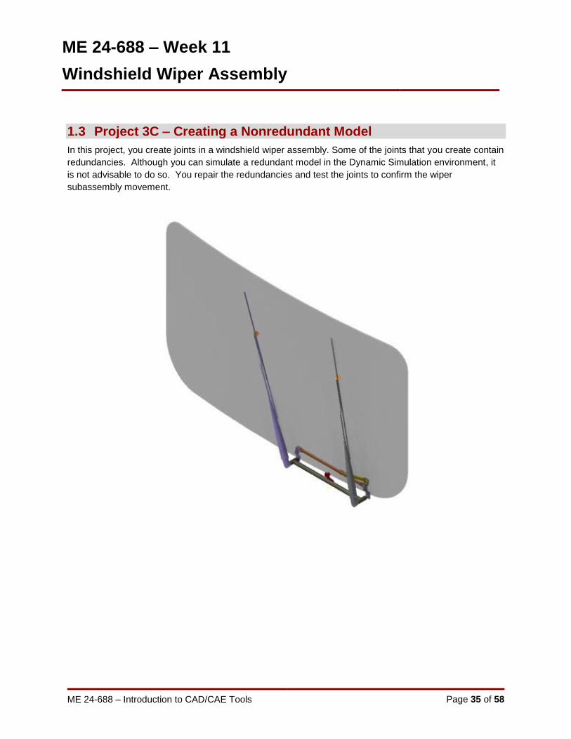
1.3 Project 3C – Creating a Nonredundant Model
In this project, you create joints in a windshield wiper assembly. Some of the joints that you create contain
redundancies. Although you can simulate a redundant model in the Dynamic Simulation environment, it
is not advisable to do so. You repair the redundancies and test the joints to confirm the wiper
subassembly movement.

ME 24-688 – Week 11
Windshield Wiper Assembly
ME 24-688 – Introduction to CAD/CAE Tools Page 36 of 58
1. In this section of the project, you create revolution joints between the wiper subassemblies and
the bearings subassembly. Open the WiperAssemblyNRM.iam Autodesk Inventor assembly file
as shown below.
2. Zoom in to the wiper assembly as shown. The subassemblies Brush_asm_left (1) and the
Complete_wiper_left_asm (2) must move as a unit. In the next steps, you weld the two
subassemblies together.

ME 24-688 – Week 11
Windshield Wiper Assembly
ME 24-688 – Introduction to CAD/CAE Tools Page 37 of 58
3. Click Environments tab | Begin panel | Dynamic Simulation.
4. If you are prompted to view the tutorial, click No to close the window.
5. In the Browser:
Select Brush_asm_left:1 and Complete_wiper_left_asm:1
Right-click Brush_asm_left:1
Click Weld Parts
6. Review the Browser. A Welded group:1 is added to the Grounded node. These two
components will now move and act like one within the dynamic simulation environment.

ME 24-688 – Week 11
Windshield Wiper Assembly
ME 24-688 – Introduction to CAD/CAE Tools Page 38 of 58
7. Click on the View tab | Visibility panel | Object Visibility and select User Work Planes to turn
on the visibility of user created workplanes in the parts.
8. Click Dynamic Simulation tab | Joint panel | Insert Joint to start creating a new joint. Select
Revolution as the joint type.
ME 24-688 – Week 11
Windshield Wiper Assembly
ME 24-688 – Introduction to CAD/CAE Tools Page 39 of 58
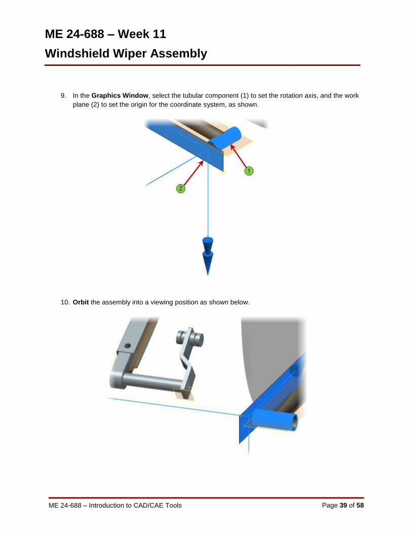
9. In the Graphics Window, select the tubular component (1) to set the rotation axis, and the work
plane (2) to set the origin for the coordinate system, as shown.
10. Orbit the assembly into a viewing position as shown below.

ME 24-688 – Week 11
Windshield Wiper Assembly
ME 24-688 – Introduction to CAD/CAE Tools Page 40 of 58
11. In the Insert Joint dialog box, under Component 2, click the Second Selection button.
12. Click the circular edge as shown to specify the joint origin on the welded assembly.
13. Notice that the two coordinate systems are in general alignment. Click OK to create the joint.
Now notice that the two welded group components moved into position as one single item.
14. On the ViewCube, click Home.

ME 24-688 – Week 11
Windshield Wiper Assembly
ME 24-688 – Introduction to CAD/CAE Tools Page 41 of 58
15. Zoom in to the assembly as shown. The Complete_wiper_right_asm (1) and the Bearings (2)
subassemblies are currently in the proper orientation.
16. Now we will create a new joint between the right wiper and the bearings. Click Insert Joint on
the Joint panel.
17. Select Revolution as the Joint Type. This will leave two DOF one rotational and transitional.
18. For Component 1 select the outer circular edge of the bearing part as shown below.

ME 24-688 – Week 11
Windshield Wiper Assembly
ME 24-688 – Introduction to CAD/CAE Tools Page 42 of 58
19. For Component 2 select the cylindrical face as shown below on the right wiper.
20. Select the inner face of the wiper mounting arm as shown below as the Origin for Component 2.
21. To ensure the two coordinate systems are in alignment Flip Z Direction on Component 2.

ME 24-688 – Week 11
Windshield Wiper Assembly
ME 24-688 – Introduction to CAD/CAE Tools Page 43 of 58
22. Click OK to create the revolution joint. You will notice the wiper part position moved to align the
two coordinate systems as shown below.
23. To move the wiper back into the starting position right-click on the Revolution:2 standard joint in
the Browser and select Properties.
24. In the Revolution:2 dialog complete the following:
Click the dof 1 ( R ) tab
Select Edit Initial Conditions
For the Position enter 56.73 deg
Click OK
25. On the ViewCube, click Home.
ME 24-688 – Week 11
Windshield Wiper Assembly
ME 24-688 – Introduction to CAD/CAE Tools Page 44 of 58
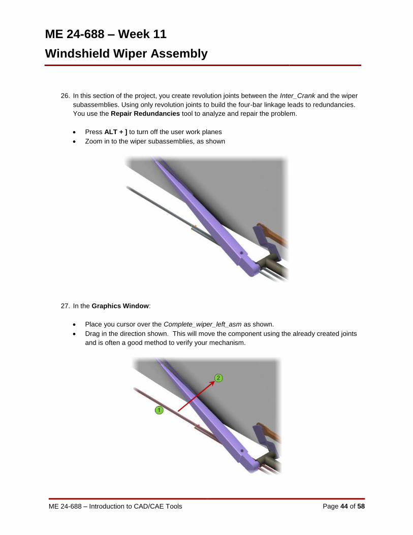
26. In this section of the project, you create revolution joints between the Inter_Crank and the wiper
subassemblies. Using only revolution joints to build the four-bar linkage leads to redundancies.
You use the Repair Redundancies tool to analyze and repair the problem.
Press ALT + ] to turn off the user work planes
Zoom in to the wiper subassemblies, as shown
27. In the Graphics Window:
Place you cursor over the Complete_wiper_left_asm as shown.
Drag in the direction shown. This will move the component using the already created joints
and is often a good method to verify your mechanism.
ME 24-688 – Week 11
Windshield Wiper Assembly
ME 24-688 – Introduction to CAD/CAE Tools Page 45 of 58
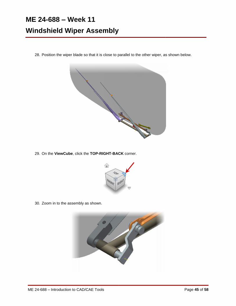
28. Position the wiper blade so that it is close to parallel to the other wiper, as shown below.
29. On the ViewCube, click the TOP-RIGHT-BACK corner.
30. Zoom in to the assembly as shown.

ME 24-688 – Week 11
Windshield Wiper Assembly
ME 24-688 – Introduction to CAD/CAE Tools Page 46 of 58
31. Drag the Inter_Crank to a new location, as shown. Now you create a revolution joint between the
Inter_Crank and the Complete_wiper_left_asm.
32. On the Joint panel, click Insert Joint.
33. In the Insert Joint dialog box, verify that the Revolution joint is active.
ME 24-688 – Week 11
Windshield Wiper Assembly
ME 24-688 – Introduction to CAD/CAE Tools Page 47 of 58
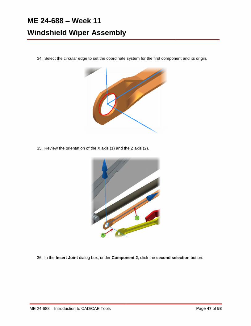
34. Select the circular edge to set the coordinate system for the first component and its origin.
35. Review the orientation of the X axis (1) and the Z axis (2).
36. In the Insert Joint dialog box, under Component 2, click the second selection button.
ME 24-688 – Week 11
Windshield Wiper Assembly
ME 24-688 – Introduction to CAD/CAE Tools Page 48 of 58
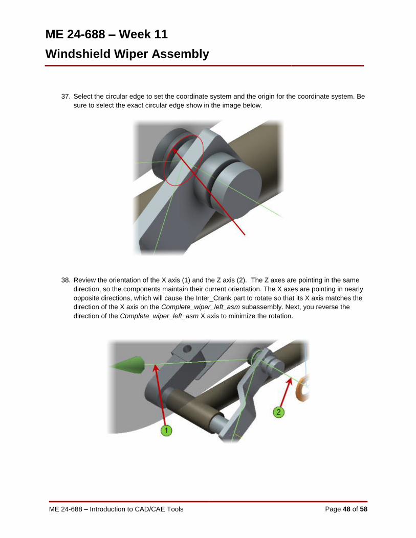
37. Select the circular edge to set the coordinate system and the origin for the coordinate system. Be
sure to select the exact circular edge show in the image below.
38. Review the orientation of the X axis (1) and the Z axis (2). The Z axes are pointing in the same
direction, so the components maintain their current orientation. The X axes are pointing in nearly
opposite directions, which will cause the Inter_Crank part to rotate so that its X axis matches the
direction of the X axis on the Complete_wiper_left_asm subassembly. Next, you reverse the
direction of the Complete_wiper_left_asm X axis to minimize the rotation.

ME 24-688 – Week 11
Windshield Wiper Assembly
ME 24-688 – Introduction to CAD/CAE Tools Page 49 of 58
39. In the Insert Joint dialog box, under Component 2, click Flip X Axis. The X axis for the
Complete_wiper_left_asm subassembly reverses direction.
40. Click OK. The joint is created. Now you create a revolution joint between the other end of the
Inter_Crank component and the Complete_wiper_right_asm subassembly.
41. On the Joint panel, click Insert Joint.

ME 24-688 – Week 11
Windshield Wiper Assembly
ME 24-688 – Introduction to CAD/CAE Tools Page 50 of 58
42. Pan to the right as shown.
43. Select the circular edge shown in the image below to set the origin of the coordinate system for
the first component. This should be the edge on the opposite side.
44. In the Insert Joint dialog box, under Component 2, click the second selection button.

ME 24-688 – Week 11
Windshield Wiper Assembly
ME 24-688 – Introduction to CAD/CAE Tools Page 51 of 58
45. In the Graphics Window, pan over to the end of the Complete_wiper_right_asm, as shown.
46. Select the circular edge to set the origin of the coordinate system for the second component.

ME 24-688 – Week 11
Windshield Wiper Assembly
ME 24-688 – Introduction to CAD/CAE Tools Page 52 of 58
47. Review the two coordinate system axes. With the Z axes (1) and the X axes (2) for the two
components pointing in opposite directions, one of the components tries to flip to match the Z axis
of the other component and rotate to match the X axis, causing the joint to fail. Next, you reverse
the direction of the X and Z axes of Component 2 to create a successful joint.
48. In the Insert Joint dialog box:
Under Component 2, click Flip Z Direction. The Z axis reverses direction.
Under Component 2, click Flip X Direction. The X axis reverses direction.
Click OK.
The axes should resemble the image below.

ME 24-688 – Week 11
Windshield Wiper Assembly
ME 24-688 – Introduction to CAD/CAE Tools Page 53 of 58
49. A warning box is displayed stating that the mechanism is impossible to assemble.
Click OK to close the warning.
50. In the browser, review the Standard Joints group. The Revolution:4 (Inter_Crank:1,
Complete_wiper_right_asm:1) joint is shown with an icon indicating that it has been suppressed.
Next you will repair this redundancy in the joint of being over constrained.
51. Delete the Revolution:4 joint by right-clicking in the Browser and selecting Delete from the menu.
52. Now we will create a different type of joint. Click Insert Joint from the Joint panel and select
Point-Line as the joint type.
53. Select the same geometry for Component 1 and Component 2 as before.
ME 24-688 – Week 11
Windshield Wiper Assembly
ME 24-688 – Introduction to CAD/CAE Tools Page 54 of 58
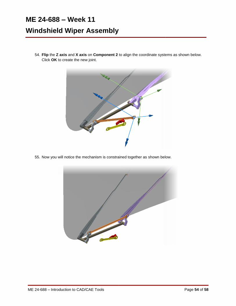
54. Flip the Z axis and X axis on Component 2 to align the coordinate systems as shown below.
Click OK to create the new joint.
55. Now you will notice the mechanism is constrained together as shown below.
ME 24-688 – Week 11
Windshield Wiper Assembly
ME 24-688 – Introduction to CAD/CAE Tools Page 55 of 58
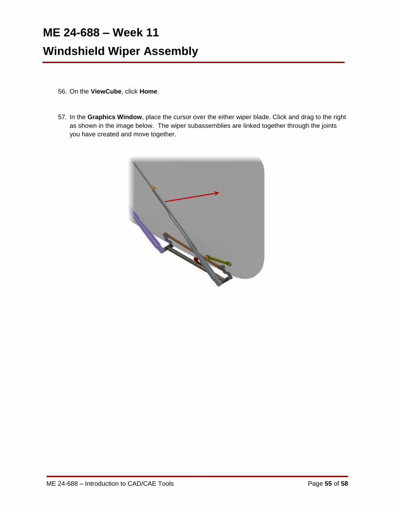
56. On the ViewCube, click Home.
57. In the Graphics Window, place the cursor over the either wiper blade. Click and drag to the right
as shown in the image below. The wiper subassemblies are linked together through the joints
you have created and move together.
ME 24-688 – Week 11
Windshield Wiper Assembly
ME 24-688 – Introduction to CAD/CAE Tools Page 56 of 58
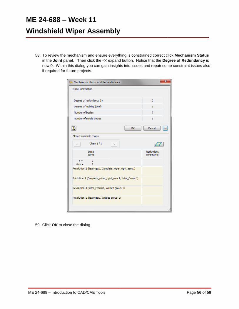
58. To review the mechanism and ensure everything is constrained correct click Mechanism Status
in the Joint panel. Then click the << expand button. Notice that the Degree of Redundancy is
now 0. Within this dialog you can gain insights into issues and repair some constraint issues also
if required for future projects.
59. Click OK to close the dialog.

ME 24-688 – Week 11
Windshield Wiper Assembly
ME 24-688 – Introduction to CAD/CAE Tools Page 57 of 58
60. Notice in the Browser there are three Mobile Groups listed at the first level. These three groups
of components move and operate as separate groups in the mechanism based upon the joint
relationships.
61. Click Simulation Settings in the Manage panel. Check the Color Mobile Groups checkbox and
click OK.

ME 24-688 – Week 11
Windshield Wiper Assembly
ME 24-688 – Introduction to CAD/CAE Tools Page 58 of 58
62. Notice how all of the components within each of the mobile groups are displayed as the same
color now. This greatly helps understand the relationships and kinematics loops within your
mechanism.
63. Save the assembly so you can review the items later if required.
Related Documents