
Welcome message from author
This document is posted to help you gain knowledge. Please leave a comment to let me know what you think about it! Share it to your friends and learn new things together.
Transcript
Introduction
Thank you for selecting the Mitsubishi numerical control unit. This instruction manual describes the
handling and caution points for using this AC servo/spindle.Incorrect handling may lead to unforeseen
accidents, so always read this instruction manual thoroughly to ensure correct usage.
In order to confirm if all function specifications described in this manual are applicable, refer to the
specifications for each CNC.
Notes on Reading This Manual
(1) Since the description of this specification manual deals with NC in general, for the specifications of
individual machine tools, refer to the manuals issued by the respective machine manufacturers.
The "restrictions" and "available functions" described in the manuals issued by the machine
manufacturers have precedence to those in this manual.
(2) This manual describes as many special operations as possible, but it should be kept in mind that
items not mentioned in this manual cannot be performed.


Precautions for safety
Please read this manual and auxiliary documents before starting installation, operation, maintenance or
inspection to ensure correct usage. Thoroughly understand the device, safety information and
precautions before starting operation.
The safety precautions in this instruction manual are ranked as "WARNING" and "CAUTION".
Note that some items described as " CAUTION" may lead to major results depending on the situation.
In any case, important information that must be observed is described.
When there is a potential risk of fatal or serious injuries if handling is mistaken.
When a dangerous situation, or fatal or serious injuries may occur if handling is mistaken.
When a dangerous situation may occur if handling is mistaken leading to medium or minor
injuries, or physical damage.
DANGER
WARNING
CAUTION
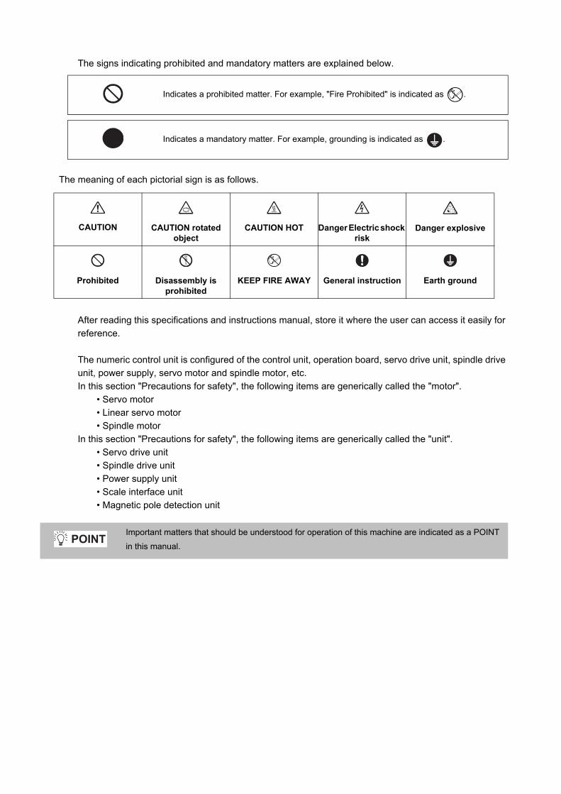
The signs indicating prohibited and mandatory matters are explained below.
The meaning of each pictorial sign is as follows.
After reading this specifications and instructions manual, store it where the user can access it easily for
reference.
The numeric control unit is configured of the control unit, operation board, servo drive unit, spindle drive
unit, power supply, servo motor and spindle motor, etc.
In this section "Precautions for safety", the following items are generically called the "motor".
• Servo motor
• Linear servo motor
• Spindle motor
In this section "Precautions for safety", the following items are generically called the "unit".
• Servo drive unit
• Spindle drive unit
• Power supply unit
• Scale interface unit
• Magnetic pole detection unit
Indicates a prohibited matter. For example, "Fire Prohibited" is indicated as .
Indicates a mandatory matter. For example, grounding is indicated as .
CAUTION
CAUTION rotated
object
CAUTION HOT
Danger Electric shock
risk
Danger explosive
Prohibited
Disassembly is
prohibited
KEEP FIRE AWAY
General instruction
Earth ground
Important matters that should be understood for operation of this machine are indicated as a POINT
in this manual. POINT

1. Electric shock prevention
Do not open the front cover while the power is ON or during operation. Failure to observe this could lead
to electric shocks.
Do not operate the unit with the front cover removed. The high voltage terminals and charged sections
will be exposed, and can cause electric shocks.
Do not remove the front cover and connector even when the power is OFF unless carrying out wiring
work or periodic inspections. The inside of the units is charged, and can cause electric shocks.
Since the high voltage is supplied to the main circuit connector while the power is ON or during
operation, do not touch the main circuit connector with an adjustment screwdriver or the pen tip. Failure
to observe this could lead to electric shocks.
Wait at least 15 minutes after turning the power OFF, confirm that the CHARGE lamp has gone out, and
check the voltage between P and N terminals with a tester, etc., before starting wiring, maintenance or
inspections. Failure to observe this could lead to electric shocks.
Ground the unit and motor. For the motor, ground it via the drive unit.
Wiring, maintenance and inspection work must be done by a qualified technician.
Wire the servo drive unit and servo motor after installation. Failure to observe this could lead to electric
shocks.
Do not touch the switches with wet hands. Failure to observe this could lead to electric shocks.
Do not damage, apply forcible stress, place heavy items on the cables or get them caught. Failure to
observe this could lead to electric shocks.
Always insulate the power terminal connection section. Failure to observe this could lead to electric
shocks.
After assembling the built-in IPM spindle motor, if the rotor is rotated by hand etc., voltage occurs
between the terminals of lead. Take care not to get electric shocks.
WARNING

2. Injury prevention
When handling a motor, perform operations in safe clothing.
In the system where the optical communication with CNC is executed, do not see directly the light
generated from CN1A/CN1B connector of drive unit or the end of cable. When the light gets into eye,
you may feel something is wrong for eye.
(The light source of optical communication corresponds to class1 defined in JISC6802 or IEC60825-1.)
The linear servo motor, direct-drive motor and built-in IPM spindle motor uses permanent magnets in
the rotor, so observe the following precautions.
(1)Handling
• The linear servo motor, direct-drive motor and built-in IPM spindle motor could adversely affect
medical electronics such as pacemakers, etc., therefore, do not approach the rotor.
• Do not place magnetic materials as iron.
• When a magnetic material as iron is placed, take safety measure not to pinch fingers or hands
due to the magnetic attraction force.
• Remove metal items such as watch, piercing jewelry, necklace, etc.
• Do not place portable items that could malfunction or fail due to the influence of the magnetic
force.
• When the rotor is not securely fixed to the machine or device, do not leave it unattended but store
it in the package properly.
• When installing the motor to the machine, take it out from the package one by one, and then install
it.
• It is highly dangerous to lay out the motor or magnetic plates together on the table or pallet,
therefore never do so.
(2)Transportation and storage
• Correctly store the rotor in the package to transport and store.
• During transportation and storage, draw people's attention by applying a notice saying "Strong
magnet-Handle with care" to the package or storage shelf.
• Do not use a damaged package.
(3)Installation
• Take special care not to pinch fingers, etc., when installing (and unpacking) the linear servo
motor.
WARNING
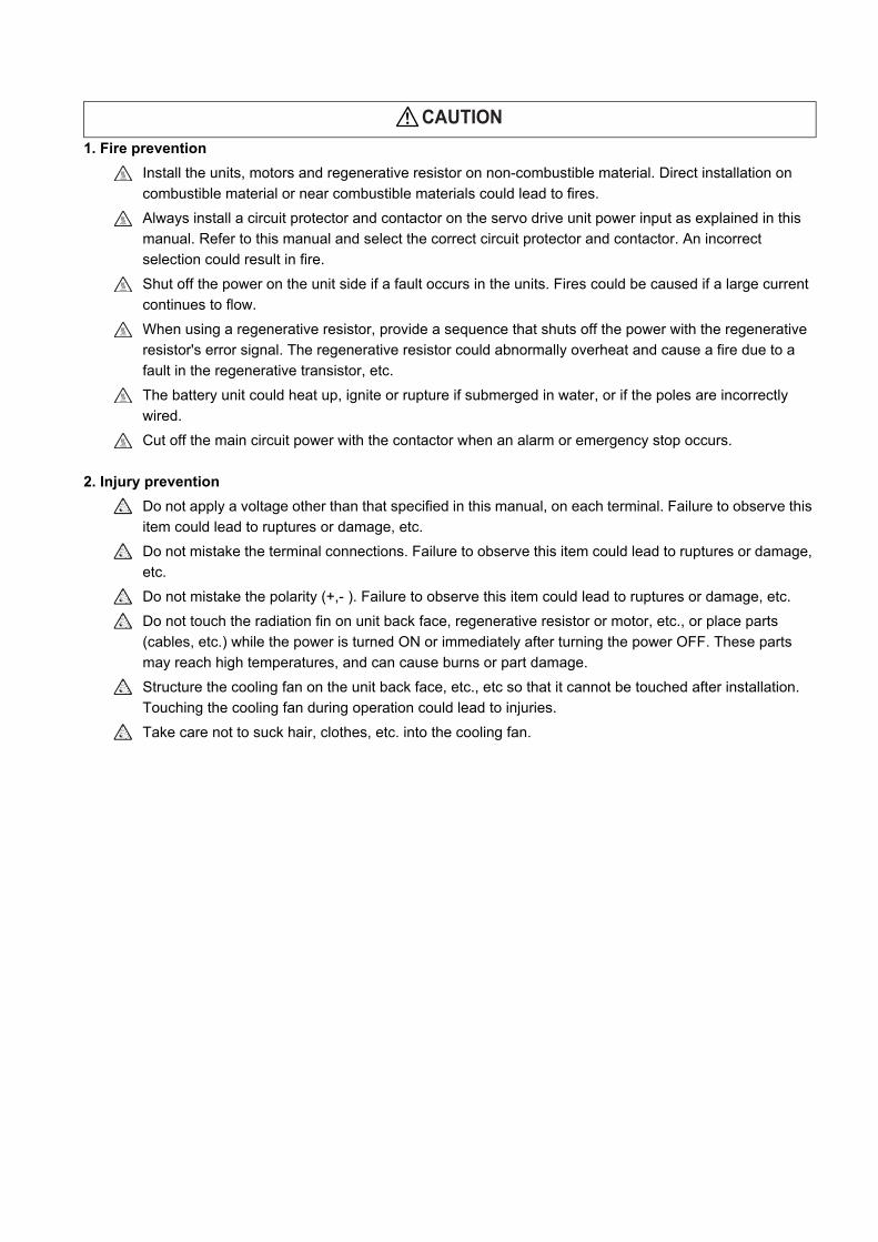
1. Fire prevention
Install the units, motors and regenerative resistor on non-combustible material. Direct installation on
combustible material or near combustible materials could lead to fires.
Always install a circuit protector and contactor on the servo drive unit power input as explained in this
manual. Refer to this manual and select the correct circuit protector and contactor. An incorrect
selection could result in fire.
Shut off the power on the unit side if a fault occurs in the units. Fires could be caused if a large current
continues to flow.
When using a regenerative resistor, provide a sequence that shuts off the power with the regenerative
resistor's error signal. The regenerative resistor could abnormally overheat and cause a fire due to a
fault in the regenerative transistor, etc.
The battery unit could heat up, ignite or rupture if submerged in water, or if the poles are incorrectly
wired.
Cut off the main circuit power with the contactor when an alarm or emergency stop occurs.
2. Injury prevention
Do not apply a voltage other than that specified in this manual, on each terminal. Failure to observe this
item could lead to ruptures or damage, etc.
Do not mistake the terminal connections. Failure to observe this item could lead to ruptures or damage,
etc.
Do not mistake the polarity (+,- ). Failure to observe this item could lead to ruptures or damage, etc.
Do not touch the radiation fin on unit back face, regenerative resistor or motor, etc., or place parts
(cables, etc.) while the power is turned ON or immediately after turning the power OFF. These parts
may reach high temperatures, and can cause burns or part damage.
Structure the cooling fan on the unit back face, etc., etc so that it cannot be touched after installation.
Touching the cooling fan during operation could lead to injuries.
Take care not to suck hair, clothes, etc. into the cooling fan.
CAUTION
3. Various precautions
Observe the following precautions. Incorrect handling of the unit could lead to faults, injuries and electric
shocks, etc.
(1) Transportation and installation
Correctly transport the product according to its weight.
Use the motor's hanging bolts only when transporting the motor. Do not transport the machine when the
motor is installed on the machine.
Do not stack the products above the tolerable number.
Follow this manual and install the unit or motor in a place where the weight can be borne.
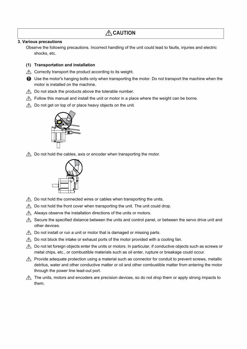
Do not get on top of or place heavy objects on the unit.
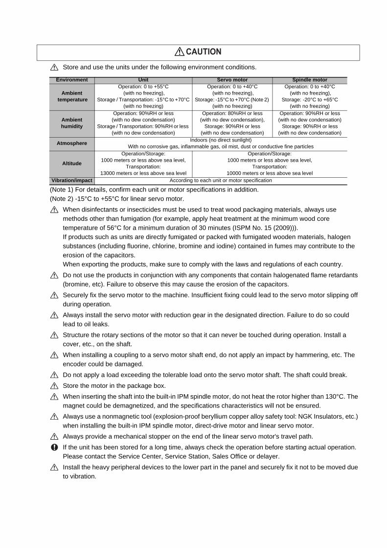
Do not hold the cables, axis or encoder when transporting the motor.
Do not hold the connected wires or cables when transporting the units.
Do not hold the front cover when transporting the unit. The unit could drop.
Always observe the installation directions of the units or motors.
Secure the specified distance between the units and control panel, or between the servo drive unit and
other devices.
Do not install or run a unit or motor that is damaged or missing parts.
Do not block the intake or exhaust ports of the motor provided with a cooling fan.
Do not let foreign objects enter the units or motors. In particular, if conductive objects such as screws or
metal chips, etc., or combustible materials such as oil enter, rupture or breakage could occur.
Provide adequate protection using a material such as connector for conduit to prevent screws, metallic
detritus, water and other conductive matter or oil and other combustible matter from entering the motor
through the power line lead-out port.
The units, motors and encoders are precision devices, so do not drop them or apply strong impacts to
them.
CAUTION
Store and use the units under the following environment conditions.
(Note 1) For details, confirm each unit or motor specifications in addition.
(Note 2) -15°C to +55°C for linear servo motor.
When disinfectants or insecticides must be used to treat wood packaging materials, always use
methods other than fumigation (for example, apply heat treatment at the minimum wood core
temperature of 56°C for a minimum duration of 30 minutes (ISPM No. 15 (2009))).
If products such as units are directly fumigated or packed with fumigated wooden materials, halogen
substances (including fluorine, chlorine, bromine and iodine) contained in fumes may contribute to the
erosion of the capacitors.
When exporting the products, make sure to comply with the laws and regulations of each country.
Do not use the products in conjunction with any components that contain halogenated flame retardants
(bromine, etc). Failure to observe this may cause the erosion of the capacitors.
Securely fix the servo motor to the machine. Insufficient fixing could lead to the servo motor slipping off
during operation.
Always install the servo motor with reduction gear in the designated direction. Failure to do so could
lead to oil leaks.
Structure the rotary sections of the motor so that it can never be touched during operation. Install a
cover, etc., on the shaft.
When installing a coupling to a servo motor shaft end, do not apply an impact by hammering, etc. The
encoder could be damaged.
Do not apply a load exceeding the tolerable load onto the servo motor shaft. The shaft could break.
Store the motor in the package box.
When inserting the shaft into the built-in IPM spindle motor, do not heat the rotor higher than 130°C. The
magnet could be demagnetized, and the specifications characteristics will not be ensured.
Always use a nonmagnetic tool (explosion-proof beryllium copper alloy safety tool: NGK Insulators, etc.)
when installing the built-in IPM spindle motor, direct-drive motor and linear servo motor.
Always provide a mechanical stopper on the end of the linear servo motor's travel path.
If the unit has been stored for a long time, always check the operation before starting actual operation.
Please contact the Service Center, Service Station, Sales Office or delayer.
Install the heavy peripheral devices to the lower part in the panel and securely fix it not to be moved due
to vibration.
Environment Unit Servo motor Spindle motor
Ambient temperature
Operation: 0 to +55°C (with no freezing),
Storage / Transportation: -15°C to +70°C(with no freezing)
Operation: 0 to +40°C (with no freezing),
Storage: -15°C to +70°C (Note 2) (with no freezing)
Operation: 0 to +40°C (with no freezing),
Storage: -20°C to +65°C(with no freezing)
Ambient humidity
Operation: 90%RH or less (with no dew condensation)
Storage / Transportation: 90%RH or less (with no dew condensation)
Operation: 80%RH or less (with no dew condensation),
Storage: 90%RH or less (with no dew condensation)
Operation: 90%RH or less (with no dew condensation)
Storage: 90%RH or less (with no dew condensation)
AtmosphereIndoors (no direct sunlight)
With no corrosive gas, inflammable gas, oil mist, dust or conductive fine particles
Altitude
Operation/Storage: 1000 meters or less above sea level,
Transportation: 13000 meters or less above sea level
Operation/Storage:1000 meters or less above sea level,
Transportation: 10000 meters or less above sea level
Vibration/impact According to each unit or motor specification
CAUTION
(2) Wiring
Correctly and securely perform the wiring. Failure to do so could lead to abnormal operation of the
motor.
Do not install a condensing capacitor, surge absorber or radio noise filter on the output side of the drive
unit.
Correctly connect the output side of the drive unit (terminals U, V, W). Failure to do so could lead to
abnormal operation of the motor.
When using a power regenerative power supply unit, always install an AC reactor for each power supply
unit.
In the main circuit power supply side of the unit, always install an appropriate circuit protector or
contactor for each unit. Circuit protector or contactor cannot be shared by several units.
Always connect the motor to the drive unit's output terminals (U, V, W).
Do not directly connect a commercial power supply to the servo motor. Failure to observe this could
result in a fault.
When using an inductive load such as a relay, always connect a diode as a noise measure parallel to
the load.
When using a capacitance load such as a lamp, always connect a protective resistor as a noise
measure serial to the load.
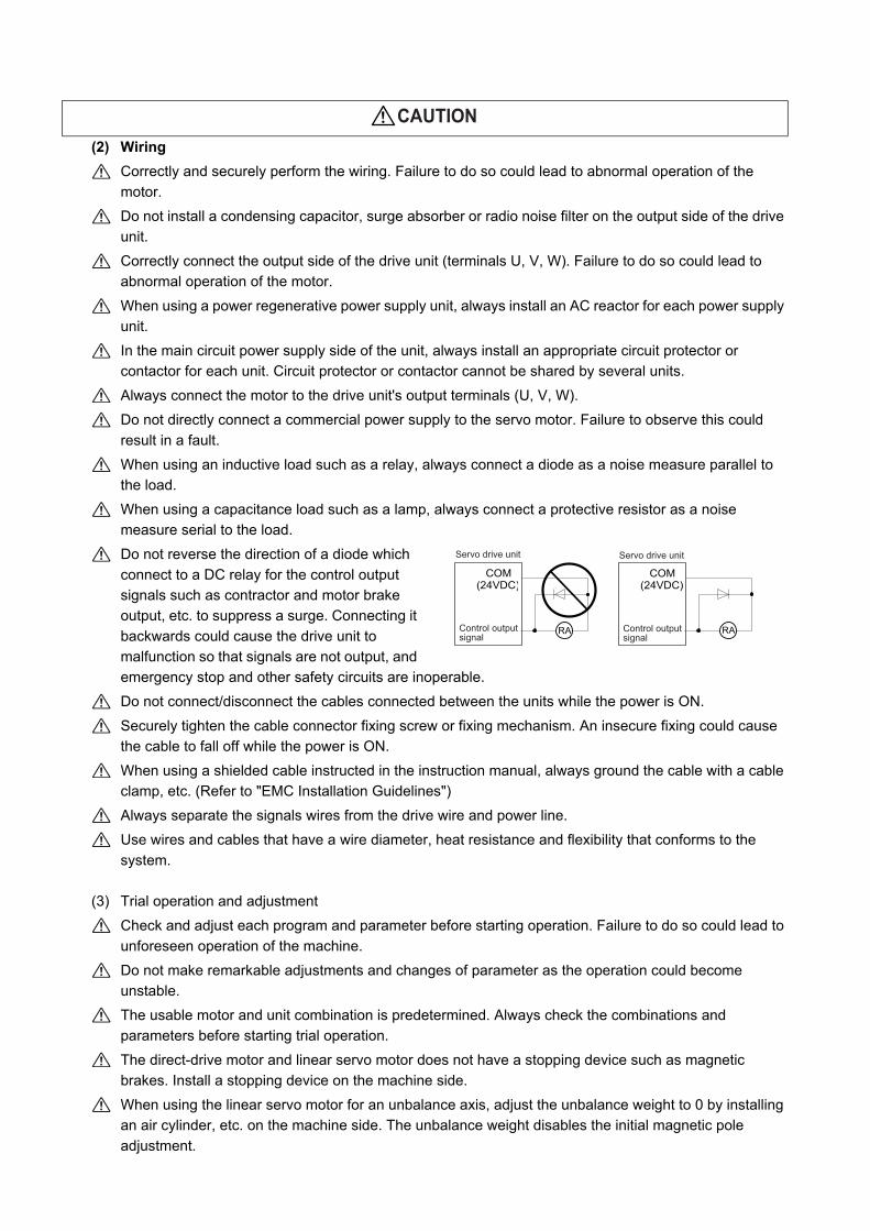
Do not reverse the direction of a diode which
connect to a DC relay for the control output
signals such as contractor and motor brake
output, etc. to suppress a surge. Connecting it
backwards could cause the drive unit to
malfunction so that signals are not output, and
emergency stop and other safety circuits are inoperable.
Do not connect/disconnect the cables connected between the units while the power is ON.
Securely tighten the cable connector fixing screw or fixing mechanism. An insecure fixing could cause
the cable to fall off while the power is ON.
When using a shielded cable instructed in the instruction manual, always ground the cable with a cable
clamp, etc. (Refer to "EMC Installation Guidelines")
Always separate the signals wires from the drive wire and power line.
Use wires and cables that have a wire diameter, heat resistance and flexibility that conforms to the
system.
(3) Trial operation and adjustment
Check and adjust each program and parameter before starting operation. Failure to do so could lead to
unforeseen operation of the machine.
Do not make remarkable adjustments and changes of parameter as the operation could become
unstable.
The usable motor and unit combination is predetermined. Always check the combinations and
parameters before starting trial operation.
The direct-drive motor and linear servo motor does not have a stopping device such as magnetic
brakes. Install a stopping device on the machine side.
When using the linear servo motor for an unbalance axis, adjust the unbalance weight to 0 by installing
an air cylinder, etc. on the machine side. The unbalance weight disables the initial magnetic pole
adjustment.
CAUTION
RA
COM(24VDC)
COM(24VDC)
RA
Servo drive unit Servo drive unit
Control outputsignal
Control outputsignal
(4) Usage methods
In abnormal state, install an external emergency stop circuit so that the operation can be stopped and
power shut off immediately.
Turn the power OFF immediately if smoke, abnormal noise or odors are generated from the unit or
motor.
Do not disassemble or repair this product.
Never make modifications.
When an alarm occurs, the machine will start suddenly if an alarm reset (RST) is carried out while an
operation start signal (ST) is being input. Always confirm that the operation signal is OFF before
carrying out an alarm reset. Failure to do so could lead to accidents or injuries.
Reduce magnetic damage by installing a noise filter. The electronic devices used near the unit could be
affected by magnetic noise. Install a line noise filter, etc., if there is a risk of magnetic noise.
Use the unit, motor and regenerative resistor with the designated combination. Failure to do so could
lead to fires or trouble.
The brake (magnetic brake) of the servo motor are for holding, and must not be used for normal braking.
There may be cases when holding is not possible due to the magnetic brake's life, the machine
construction (when ball screw and servo motor are coupled via a timing belt, etc.) or the magnetic
brake's failure. Install a stop device to ensure safety on the machine side.
After changing the programs/parameters or after maintenance and inspection, always test the operation
before starting actual operation.
Do not enter the movable range of the machine during automatic operation. Never place body parts
near or touch the spindle during rotation.
Follow the power supply specification conditions given in each specification for the power (input voltage,
input frequency, tolerable sudden power failure time, etc.).
Set all bits to "0" if they are indicated as not used or empty in the explanation on the bits.
Do not use the dynamic brakes except during the emergency stop. Continued use of the dynamic
brakes could result in brake damage.
If a circuit protector for the main circuit power supply is shared by several units, the circuit protector may
not activate when a short-circuit fault occurs in a small capacity unit. This is dangerous, so never share
the circuit protector.
Mitsubishi spindle motor is dedicated to machine tools. Do not use for other purposes.
(5) Troubleshooting
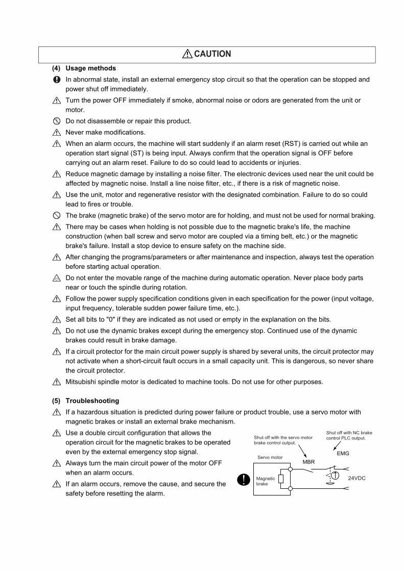
If a hazardous situation is predicted during power failure or product trouble, use a servo motor with
magnetic brakes or install an external brake mechanism.
Use a double circuit configuration that allows the
operation circuit for the magnetic brakes to be operated
even by the external emergency stop signal.
Always turn the main circuit power of the motor OFF
when an alarm occurs.
If an alarm occurs, remove the cause, and secure the
safety before resetting the alarm.
CAUTION
MBREMG
Servo motor
Magneticbrake
Shut off with the servo motorbrake control output.
Shut off with NC brake control PLC output.
24VDC
(6) Maintenance, inspection and part replacement
Always backup the programs and parameters before starting maintenance or inspections.
The capacity of the electrolytic capacitor will drop over time due to self-discharging, etc. To prevent
secondary disasters due to failures, replacing this part every five years when used under a normal
environment is recommended. Contact the Service Center, Service Station, Sales Office or delayer for
repairs or part replacement.
Do not perform a megger test (insulation resistance measurement) during inspections.
If the battery low warning is issued, immediately replace the battery. Replace the batteries while
applying the drive unit's control power.
Do not short circuit, charge, overheat, incinerate or disassemble the battery.
For after-purchase servicing of the built-in motor, only the servicing parts for MITSUBISHI encoder can
be supplied. For the motor body, prepare the spare parts at the machine manufacturers.
For maintenance, part replacement, and services in case of failures in the built-in motor (including the
encoder), take necessary actions at the machine manufacturers. For spindle drive unit, Mitsubishi can
offer the after-purchase servicing as with the general spindle drive unit.
(7) Disposal
Take the batteries and backlights for LCD, etc., off from the controller, drive unit and motor, and dispose
of them as general industrial wastes.
Do not disassemble the unit or motor.
Dispose of the battery according to local laws.
Always return the secondary side (magnet side) of the linear servo motor to the Service Center or
Service Station.
When incinerating optical communication cable, hydrogen fluoride gas or hydrogen chloride gas which
is corrosive and harmful may be generated. For disposal of optical communication cable, request for
specialized industrial waste disposal services that has incineration facility for disposing hydrogen
fluoride gas or hydrogen chloride gas.
(8) Transportation
The unit and motor are precision parts and must be handled carefully.
According to a United Nations Advisory, the battery unit and battery must be transported according to
the rules set forth by the International Civil Aviation Organization (ICAO), International Air
Transportation Association (IATA), International Maritime Organization (IMO), and United States
Department of Transportation (DOT), etc.
(9) General precautions
The drawings given in this manual show the covers and safety partitions, etc., removed to provide a
clearer explanation. Always return the covers or partitions to their respective places before starting
operation, and always follow the instructions given in this manual.
CAUTION
Treatment of waste
The following two laws will apply when disposing of this product. Considerations must be made to each law.
The following laws are in effect in Japan. Thus, when using this product overseas, the local laws will have a
priority. If necessary, indicate or notify these laws to the final user of the product.
(1) Requirements for "Law for Promotion of Effective Utilization of Resources"
(a) Recycle as much of this product as possible when finished with use.
(b) When recycling, often parts are sorted into steel scraps and electric parts, etc., and sold to scrap
contractors. Mitsubishi recommends sorting the product and selling the members to appropriate
contractors.
(2) Requirements for "Law for Treatment of Waste and Cleaning"
(a) Mitsubishi recommends recycling and selling the product when no longer needed according to item
(1) above. The user should make an effort to reduce waste in this manner.
(b) When disposing a product that cannot be resold, it shall be treated as a waste product.
(c) The treatment of industrial waste must be commissioned to a licensed industrial waste treatment
contractor, and appropriate measures, including a manifest control, must be taken.
(d) Batteries correspond to "primary batteries", and must be disposed of according to local disposal
laws.


Disposal
(Note) This symbol mark is for EU countries only.
This symbol mark is according to the directive 2006/66/EC Article 20 Information for end-
users and Annex II.
Your MITSUBISHI ELECTRIC product is designed and manufactured with high quality materials and
components which can be recycled and/or reused.
This symbol means that batteries and accumulators, at their end-of-life, should be disposed of
separately from your household waste.
If a chemical symbol is printed beneath the symbol shown above, this chemical symbol means that the
battery or accumulator contains a heavy metal at a certain concentration. This will be indicated as
follows:
Hg: mercury (0,0005%), Cd: cadmium (0,002%), Pb: lead (0,004%)
In the European Union there are separate collection systems for used batteries and accumulators.
Please, dispose of batteries and accumulators correctly at your local community waste collection/
recycling centre.
Please, help us to conserve the environment we live in!


Trademarks
MELDAS, MELSEC, EZSocket, EZMotion, iQ Platform, MELSOFT, GOT, CC-Link, CC-Link/LT and CC-Link
IE are either trademarks or registered trademarks of Mitsubishi Electric Corporation in Japan and/or other
countries.
Other company and product names that appear in this manual are trademarks or registered trademarks of the
respective companies.

本製品の取扱いについて
( 日本語 /Japanese)
本製品は工業用 ( クラス A) 電磁環境適合機器です。販売者あるいは使用者はこの点に注意し、住商業環境以外で
の使用をお願いいたします。
Handling of our product
(English)
This is a class A product. In a domestic environment this product may cause radio interference in which case the
user may be required to take adequate measures.
본 제품의 취급에 대해서
( 한국어 /Korean)
이 기기는 업무용 (A 급 ) 전자파적합기기로서 판매자 또는 사용자는 이 점을 주의하시기 바라며 가정외의 지역에
서 사용하는 것을 목적으로 합니다 .

WARRANTY Please confirm the following product warranty details before using MITSUBISHI CNC. 1. Warranty Period and Coverage
Should any fault or defect (hereafter called "failure") for which we are liable occur in this product during the warranty period, we shall provide repair services at no cost through the distributor from which the product was purchased or through a Mitsubishi Electric service provider. Note, however that this shall not apply if the customer was informed prior to purchase of the product that the product is not covered under warranty. Also note that we are not responsible for any on-site readjustment and/or trial run that may be required after a defective unit is replaced.
[Warranty Term] The term of warranty for this product shall be twenty-four (24) months from the date of delivery of product to the end user, provided the product purchased from us in Japan is installed in Japan (but in no event longer than thirty (30) months, Including the distribution time after shipment from Mitsubishi Electric or its distributor). Note that, for the case where the product purchased from us in or outside Japan is exported and installed in any country other than where it was purchased; please refer to "2. Service in overseas countries" as will be explained. [Limitations] (1) The customer is requested to conduct an initial failure diagnosis by him/herself, as a general rule. It can also be carried
out by us or our service provider upon the customer’s request and the actual cost will be charged. (2) This warranty applies only when the conditions, method, environment, etc., of use are in compliance with the terms and
conditions and instructions that are set forth in the instruction manual, user’s manual, and the caution label affixed to the product, etc.
(3) Even during the term of warranty, repair costs shall be charged to the customer in the following cases: (a) a failure caused by improper storage or handling, carelessness or negligence, etc., or a failure caused by the
customer’s hardware or software problem (b) a failure caused by any alteration, etc., to the product made by the customer without Mitsubishi Electric’s approval (c) a failure which may be regarded as avoidable, if the customer’s equipment in which this product is incorporated is
equipped with a safety device required by applicable laws or has any function or structure considered to be indispensable in the light of common sense in the industry
(d) a failure which may be regarded as avoidable if consumable parts designated in the instruction manual, etc. are duly maintained and replaced
(e) any replacement of consumable parts (including a battery, relay and fuse) (f) a failure caused by external factors such as inevitable accidents, including without limitation fire and abnormal
fluctuation of voltage, and acts of God, including without limitation earthquake, lightning, and natural disasters (g) a failure which is unforeseeable under technologies available at the time of shipment of this product from our company (h) any other failures which we are not responsible for or which the customer acknowledges we are not responsible for
2. Service in Overseas Countries
If the customer installs the product purchased from us in his/her machine or equipment, and export it to any country other than where he/she bought it, the customer may sign a paid warranty contract with our local FA center. This falls under the case where the product purchased from us in or outside Japan is exported and installed in any country other than where it was purchased. For details please contact the distributor from which the customer purchased the product. 3. Exclusion of Loss in Opportunity and Secondary Loss from Warranty Liability
Regardless of the gratis warranty term, Mitsubishi shall not be liable for compensation to: (1) Damages caused by any cause found not to be the responsibility of Mitsubishi. (2) Loss in opportunity, lost profits incurred to the user by Failures of Mitsubishi products. (3) Special damages and secondary damages whether foreseeable or not, compensation for accidents, and compensation
for damages to products other than Mitsubishi products. (4) Replacement by the user, maintenance of on-site equipment, start-up test run and other tasks.
4. Changes in Product Specifications
Specifications shown in our catalogs, manuals or technical documents are subject to change without notice. 5. Product Application
(1) For the use of this product, its applications should be those that may not result in a serious damage even if any failure or malfunction occurs in the product, and a backup or fail-safe function should operate on an external system to the product when any failure or malfunction occurs.
(2) Mitsubishi CNC is designed and manufactured solely for applications to machine tools to be used for industrial purposes. Do not use this product in any applications other than those specified above, especially those which are substantially influential on the public interest or which are expected to have significant influence on human lives or properties.


Contents
1 Introduction ............................................................................................................................................ 1 - 11-1 Servo/spindle drive system configuration ............................................................................................................1 - 2
1-1-1 System configuration ..................................................................................................................................1 - 21-2 Explanation of type ..............................................................................................................................................1 - 3
1-2-1 Servo motor type.........................................................................................................................................1 - 31-2-2 Servo drive unit type ...................................................................................................................................1 - 51-2-3 Spindle motor type ......................................................................................................................................1 - 71-2-4 Tool spindle motor type...............................................................................................................................1 - 91-2-5 Spindle drive unit type...............................................................................................................................1 - 111-2-6 Power supply unit type..............................................................................................................................1 - 121-2-7 AC reactor type .........................................................................................................................................1 - 13
2 Specifications......................................................................................................................................... 2 - 12-1 Servo motor .........................................................................................................................................................2 - 2
2-1-1 Specifications list ........................................................................................................................................2 - 22-1-2 Torque characteristics...............................................................................................................................2 - 12
2-2 Spindle motor.....................................................................................................................................................2 - 192-2-1 Specifications............................................................................................................................................2 - 192-2-2 Output characteristics ...............................................................................................................................2 - 33
2-3 Tool spindle motor .............................................................................................................................................2 - 412-3-1 Specifications............................................................................................................................................2 - 412-3-2 Output characteristics ...............................................................................................................................2 - 45
2-4 Drive unit............................................................................................................................................................2 - 472-4-1 Installation environment conditions...........................................................................................................2 - 472-4-2 Servo drive unit .........................................................................................................................................2 - 482-4-3 Spindle drive unit ......................................................................................................................................2 - 502-4-4 Power supply unit .....................................................................................................................................2 - 522-4-5 Unit outline dimension drawing .................................................................................................................2 - 532-4-6 AC reactor.................................................................................................................................................2 - 542-4-7 Explanation of each part ...........................................................................................................................2 - 57
3 Function Specifications......................................................................................................................... 3 - 1 Function specifications list ........................................................................................................................................3 - 23-1 Base control functions..........................................................................................................................................3 - 5
3-1-1 Full closed loop control ...............................................................................................................................3 - 53-1-2 Position command synchronous control .....................................................................................................3 - 63-1-3 Speed command synchronous control........................................................................................................3 - 63-1-4 Distance-coded reference position control..................................................................................................3 - 73-1-5 Spindle's continuous position loop control ..................................................................................................3 - 73-1-6 Coil changeover control ..............................................................................................................................3 - 73-1-7 Gear changeover control ............................................................................................................................3 - 73-1-8 Orientation control.......................................................................................................................................3 - 73-1-9 Indexing control...........................................................................................................................................3 - 83-1-10 Synchronous tapping control ....................................................................................................................3 - 83-1-11 Spindle synchronous control .....................................................................................................................3 - 83-1-12 Spindle/C axis control ...............................................................................................................................3 - 83-1-13 Proximity switch orientation control...........................................................................................................3 - 83-1-14 Power regeneration control .......................................................................................................................3 - 83-1-15 Resistor regeneration control ....................................................................................................................3 - 8
3-2 Servo/Spindle control functions ...........................................................................................................................3 - 93-2-1 Torque limit function....................................................................................................................................3 - 93-2-2 Variable speed loop gain control.................................................................................................................3 - 93-2-3 Gain changeover for synchronous tapping control .....................................................................................3 - 93-2-4 Speed loop PID changeover control .........................................................................................................3 - 103-2-5 Disturbance torque observer.....................................................................................................................3 - 103-2-6 Smooth High Gain control (SHG control) ..................................................................................................3 - 103-2-7 High-speed synchronous tapping control (OMR-DD control)....................................................................3 - 103-2-8 Dual feedback control ...............................................................................................................................3 - 113-2-9 HAS control ...............................................................................................................................................3 - 113-2-10 Control loop gain changeover .................................................................................................................3 - 113-2-11 Spindle output stabilizing control ............................................................................................................3 - 123-2-12 High-response spindle acceleration/deceleration function......................................................................3 - 12
3-3 Compensation control function ..........................................................................................................................3 - 133-3-1 Jitter compensation...................................................................................................................................3 - 133-3-2 Notch filter .................................................................................................................................................3 - 13
3-3-3 Adaptive tracking-type notch filter............................................................................................................. 3 - 133-3-4 Overshooting compensation ..................................................................................................................... 3 - 143-3-5 Machine end compensation control .......................................................................................................... 3 - 143-3-6 Lost motion compensation type 2 ............................................................................................................. 3 - 153-3-7 Lost motion compensation type 3 ............................................................................................................. 3 - 153-3-8 Lost motion compensation type 4 ............................................................................................................. 3 - 163-3-9 Spindle motor temperature compensation function .................................................................................. 3 - 16
3-4 Protection function............................................................................................................................................. 3 - 173-4-1 Deceleration control at emergency stop ................................................................................................... 3 - 173-4-2 Vertical axis drop prevention/pull-up control............................................................................................. 3 - 173-4-3 Earth fault detection.................................................................................................................................. 3 - 173-4-4 Collision detection function ....................................................................................................................... 3 - 183-4-5 Safety observation function ...................................................................................................................... 3 - 183-4-6 Fan stop detection .................................................................................................................................... 3 - 183-4-7 Open-phase detection .............................................................................................................................. 3 - 183-4-8 Contactor weld detection .......................................................................................................................... 3 - 18
3-5 Sequence functions ........................................................................................................................................... 3 - 193-5-1 Contactor control function......................................................................................................................... 3 - 193-5-2 Motor brake control function ..................................................................................................................... 3 - 193-5-3 External emergency stop function ............................................................................................................ 3 - 193-5-4 Specified speed output ............................................................................................................................. 3 - 193-5-5 Quick READY ON sequence .................................................................................................................... 3 - 19
3-6 Diagnosis function ............................................................................................................................................. 3 - 203-6-1 Monitor output function ............................................................................................................................. 3 - 203-6-2 Machine resonance frequency display function........................................................................................ 3 - 273-6-3 Machine inertia display function................................................................................................................ 3 - 273-6-4 Motor temperature display function .......................................................................................................... 3 - 273-6-5 Load monitor output function .................................................................................................................... 3 - 273-6-6 Open loop control function........................................................................................................................ 3 - 273-6-7 Power supply voltage display function...................................................................................................... 3 - 27
4 Characteristics ....................................................................................................................................... 4 - 14-1 Servo motor ......................................................................................................................................................... 4 - 2
4-1-1 Environmental conditions ........................................................................................................................... 4 - 24-1-2 Quakeproof level......................................................................................................................................... 4 - 24-1-3 Shaft characteristics ................................................................................................................................... 4 - 34-1-4 Machine accuracy....................................................................................................................................... 4 - 44-1-5 Oil / water standards................................................................................................................................... 4 - 54-1-6 Installation of servo motor........................................................................................................................... 4 - 64-1-7 Overload protection characteristics ............................................................................................................ 4 - 64-1-8 Magnetic brake ......................................................................................................................................... 4 - 144-1-9 Dynamic brake characteristics ................................................................................................................. 4 - 19
4-2 Spindle motor .................................................................................................................................................... 4 - 224-2-1 Environmental conditions ......................................................................................................................... 4 - 224-2-2 Shaft characteristics ................................................................................................................................. 4 - 224-2-3 Machine accuracy..................................................................................................................................... 4 - 234-2-4 Installation of spindle motor ...................................................................................................................... 4 - 23
4-3 Tool spindle motor ............................................................................................................................................. 4 - 244-3-1 Environmental conditions ......................................................................................................................... 4 - 244-3-2 Shaft characteristics ................................................................................................................................. 4 - 244-3-3 Tool spindle temperature characteristics .................................................................................................. 4 - 25
4-4 Drive unit ........................................................................................................................................................... 4 - 264-4-1 Environmental conditions ......................................................................................................................... 4 - 264-4-2 Heating value............................................................................................................................................ 4 - 274-4-3 Drive unit arrangement ............................................................................................................................. 4 - 28
5 Dedicated Options ................................................................................................................................. 5 - 15-1 Servo options....................................................................................................................................................... 5 - 2
5-1-1 Dynamic brake unit (MDS-D-DBU) ............................................................................................................. 5 - 75-1-2 Battery option (ER6V-C119B, A6BAT, MDS-A-BT, MDS-BTBOX-36) ....................................................... 5 - 95-1-3 Ball screw side encoder (OSA105ET2A, OSA166ET2NA)....................................................................... 5 - 215-1-4 Machine side encoder............................................................................................................................... 5 - 23
5-2 Spindle options .................................................................................................................................................. 5 - 275-2-1 Spindle side ABZ pulse output encoder (OSE-1024 Series) .................................................................... 5 - 285-2-2 Spindle side PLG serial output encoder (TS5690, MU1606 Series)......................................................... 5 - 305-2-3 Spindle side accuracy serial output encoder (ERM280, MPCI Series)..................................................... 5 - 345-2-4 Machine side encoder............................................................................................................................... 5 - 34
5-3 Encoder interface unit........................................................................................................................................ 5 - 35

5-3-1 Serial output interface unit for ABZ analog encoder MDS-B-HR ..............................................................5 - 355-3-2 Serial signal division unit MDS-B-SD........................................................................................................5 - 385-3-3 Pulse output interface unit for ABZ analog encoder IBV Series (Other manufacturer's product) .............5 - 405-3-4 Serial output interface unit for ABZ analog encoder EIB192M (Other manufacturer's product) ...............5 - 415-3-5 Serial output interface unit for ABZ analog encoder EIB392M (Other manufacturer's product) ...............5 - 425-3-6 Serial output interface unit for ABZ analog encoder ADB-20J Series (Other manufacturer's product).....5 - 43
5-4 Drive unit option .................................................................................................................................................5 - 445-4-1 Optical communication repeater unit (FCU7-EX022)................................................................................5 - 445-4-2 DC connection bar ....................................................................................................................................5 - 475-4-3 Side protection cover ................................................................................................................................5 - 48
5-5 Cables and connectors ......................................................................................................................................5 - 505-5-1 Cable connection diagram ........................................................................................................................5 - 505-5-2 List of cables and connectors ...................................................................................................................5 - 515-5-3 Optical communication cable specifications .............................................................................................5 - 60
6 Specifications of Peripheral Devices ................................................................................................... 6 - 16-1 Selection of wire...................................................................................................................................................6 - 2
6-1-1 Example of wires by unit .............................................................................................................................6 - 26-2 Selection of circuit protector and contactor..........................................................................................................6 - 8
6-2-1 Selection of circuit protector........................................................................................................................6 - 86-2-2 Selection of contactor .................................................................................................................................6 - 9
6-3 Selection of earth leakage breaker ....................................................................................................................6 - 106-4 Branch-circuit protection (for control power supply)...........................................................................................6 - 11
6-4-1 Circuit protector.........................................................................................................................................6 - 116-4-2 Fuse protection .........................................................................................................................................6 - 11
6-5 Noise filter ..........................................................................................................................................................6 - 126-6 Surge absorber ..................................................................................................................................................6 - 136-7 Relay..................................................................................................................................................................6 - 14
7 Selection ................................................................................................................................................. 7 - 17-1 Selection of the servo motor ................................................................................................................................7 - 2
7-1-1 Outline.........................................................................................................................................................7 - 27-1-2 Selection of servo motor capacity ...............................................................................................................7 - 37-1-3 Motor shaft conversion load torque...........................................................................................................7 - 117-1-4 Expressions for load inertia calculation.....................................................................................................7 - 12
7-2 Selection of the spindle motor............................................................................................................................7 - 137-3 Selection of the power supply unit .....................................................................................................................7 - 14
7-3-1 Calculation of spindle output .....................................................................................................................7 - 147-3-2 Calculation of servo motor output .............................................................................................................7 - 167-3-3 Selection of the power supply unit ............................................................................................................7 - 177-3-4 Required capacity of power supply ...........................................................................................................7 - 197-3-5 Example for power supply unit and power supply facility capacity............................................................7 - 20
Appendix 1 Cable and Connector Specifications .................................................................Appendix 1 - 1Appendix 1-1 Selection of cable.................................................................................................................Appendix 1 - 2
Appendix 1-1-1 Cable wire and assembly ............................................................................................Appendix 1 - 2Appendix 1-2 Cable connection diagram ...................................................................................................Appendix 1 - 5
Appendix 1-2-1 Battery cable ...............................................................................................................Appendix 1 - 5Appendix 1-2-2 Power supply communication cable and connector ....................................................Appendix 1 - 6Appendix 1-2-3 Optical communication repeater unit cable.................................................................Appendix 1 - 7Appendix 1-2-4 Servo / tool spindle encoder cable..............................................................................Appendix 1 - 8Appendix 1-2-5 Brake connector (Brake connector for motor brake control output) ..........................Appendix 1 - 13Appendix 1-2-6 Spindle encoder cable ..............................................................................................Appendix 1 - 14
Appendix 1-3 Main circuit cable connection diagram...............................................................................Appendix 1 - 16Appendix 1-4 Connector outline dimension drawings ..............................................................................Appendix 1 - 17
Appendix 1-4-1 Connector for drive unit.............................................................................................Appendix 1 - 17Appendix 1-4-2 Connector for servo and tool spindle ........................................................................Appendix 1 - 21Appendix 1-4-3 Connector for spindle................................................................................................Appendix 1 - 24
Appendix 2 Restrictions for Lithium Batteries......................................................................Appendix 2 - 1Appendix 2-1 Restriction for Packing .........................................................................................................Appendix 2 - 2
Appendix 2-1-1 Target Products ..........................................................................................................Appendix 2 - 2Appendix 2-1-2 Handling by User ........................................................................................................Appendix 2 - 3Appendix 2-1-3 Reference ...................................................................................................................Appendix 2 - 3
Appendix 2-2 Products Information Data Sheet (ER Battery) ....................................................................Appendix 2 - 4Appendix 2-3 Forbiddance of Transporting Lithium Battery by Passenger Aircraft Provided in the Code of Federal Regulation ...........................................................................................Appendix 2 - 6Appendix 2-4 California Code of Regulation "Best Management Practices for Perchlorate Materials" .....Appendix 2 - 6Appendix 2-5 Restriction Related to EU Battery Directive .........................................................................Appendix 2 - 7

Appendix 2-5-1 Important Notes .......................................................................................................... Appendix 2 - 7Appendix 2-5-2 Information for End-user ............................................................................................. Appendix 2 - 7
Appendix 3 EC Declaration of Conformity.............................................................................Appendix 3 - 1Appendix 3-1 Compliance to EC Directives............................................................................................... Appendix 3 - 2
Appendix 4 Instruction Manual for Compliance with UL/c-UL Standard ............................Appendix 4 - 1Appendix 4-1 Operation Surrounding Air Ambient Temperature ............................................................... Appendix 4 - 2Appendix 4-2 Notes for AC Servo/Spindle System.................................................................................... Appendix 4 - 2
Appendix 4-2-1 Warning ...................................................................................................................... Appendix 4 - 2Appendix 4-2-2 Installation................................................................................................................... Appendix 4 - 2Appendix 4-2-3 Short-circuit Ratings (SCCR)...................................................................................... Appendix 4 - 2Appendix 4-2-4 Over-temperature Protection for Motor....................................................................... Appendix 4 - 2Appendix 4-2-5 Peripheral Devices...................................................................................................... Appendix 4 - 3Appendix 4-2-6 Field Wiring Reference Table for Input and Output (Power Wiring) ........................... Appendix 4 - 5Appendix 4-2-7 Motor Over Load Protection ..................................................................................... Appendix 4 - 11Appendix 4-2-8 Flange of Servo Motor .............................................................................................. Appendix 4 - 12Appendix 4-2-9 Spindle Drive/Motor Combinations ........................................................................... Appendix 4 - 12Appendix 4-2-10 Servo Drive/Motor Combinations............................................................................ Appendix 4 - 14
Appendix 4-3 AC Servo/Spindle System Connection .............................................................................. Appendix 4 - 15Appendix 4-3-1 MDS-D, D2/DH, DH2/DM, DM2-Vx/SP Series ......................................................... Appendix 4 - 15Appendix 4-3-2 MDS-D/DH-CV, D/D2-Vx/SPx, DH/DH2-Vx/SPx, DM/DM2-V3 Series with MDS-D/DH-PFU .............................................................................................. Appendix 4 - 16Appendix 4-3-3 MDS-D2/DH2-CV, D/D2-Vx/SPx, DH/DH2-Vx/SPx, DM/DM2-V3 Series with MDS-D/DH-PFU .............................................................................................. Appendix 4 - 16Appendix 4-3-4 MDS-D-SVJ3/SPJ3/MDS-DJ Series......................................................................... Appendix 4 - 17Appendix 4-3-5 MDS-DM, DM2-SPV Series...................................................................................... Appendix 4 - 18
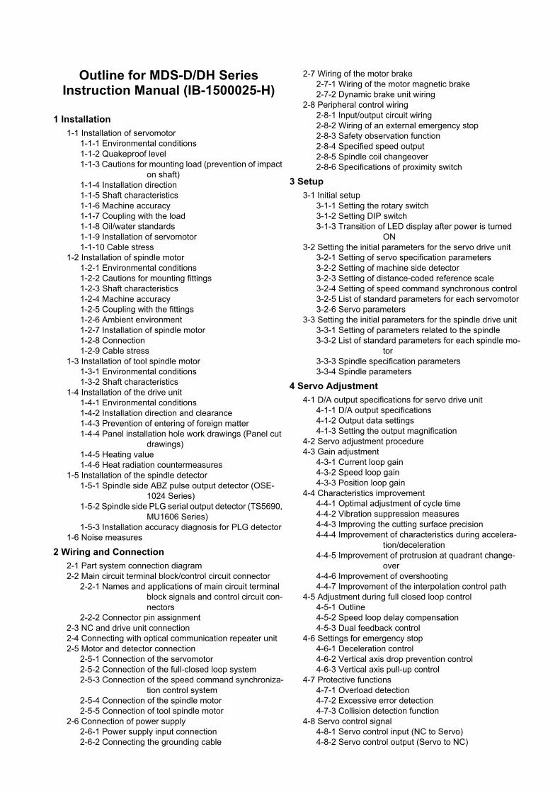
Outline for MDS-D/DH Series Instruction Manual (IB-1500025-H)
1 Installation
1-1 Installation of servomotor1-1-1 Environmental conditions1-1-2 Quakeproof level1-1-3 Cautions for mounting load (prevention of impact
on shaft)1-1-4 Installation direction1-1-5 Shaft characteristics1-1-6 Machine accuracy1-1-7 Coupling with the load1-1-8 Oil/water standards1-1-9 Installation of servomotor1-1-10 Cable stress
1-2 Installation of spindle motor1-2-1 Environmental conditions1-2-2 Cautions for mounting fittings1-2-3 Shaft characteristics1-2-4 Machine accuracy1-2-5 Coupling with the fittings1-2-6 Ambient environment1-2-7 Installation of spindle motor1-2-8 Connection1-2-9 Cable stress
1-3 Installation of tool spindle motor1-3-1 Environmental conditions1-3-2 Shaft characteristics
1-4 Installation of the drive unit1-4-1 Environmental conditions1-4-2 Installation direction and clearance1-4-3 Prevention of entering of foreign matter1-4-4 Panel installation hole work drawings (Panel cut
drawings)1-4-5 Heating value1-4-6 Heat radiation countermeasures
1-5 Installation of the spindle detector1-5-1 Spindle side ABZ pulse output detector (OSE-
1024 Series)1-5-2 Spindle side PLG serial output detector (TS5690,
MU1606 Series)1-5-3 Installation accuracy diagnosis for PLG detector
1-6 Noise measures
2 Wiring and Connection
2-1 Part system connection diagram2-2 Main circuit terminal block/control circuit connector
2-2-1 Names and applications of main circuit terminal block signals and control circuit con-nectors
2-2-2 Connector pin assignment2-3 NC and drive unit connection2-4 Connecting with optical communication repeater unit2-5 Motor and detector connection
2-5-1 Connection of the servomotor2-5-2 Connection of the full-closed loop system2-5-3 Connection of the speed command synchroniza-
tion control system2-5-4 Connection of the spindle motor2-5-5 Connection of tool spindle motor
2-6 Connection of power supply2-6-1 Power supply input connection2-6-2 Connecting the grounding cable
2-7 Wiring of the motor brake 2-7-1 Wiring of the motor magnetic brake2-7-2 Dynamic brake unit wiring
2-8 Peripheral control wiring2-8-1 Input/output circuit wiring2-8-2 Wiring of an external emergency stop2-8-3 Safety observation function2-8-4 Specified speed output2-8-5 Spindle coil changeover2-8-6 Specifications of proximity switch
3 Setup
3-1 Initial setup3-1-1 Setting the rotary switch3-1-2 Setting DIP switch3-1-3 Transition of LED display after power is turned
ON3-2 Setting the initial parameters for the servo drive unit
3-2-1 Setting of servo specification parameters3-2-2 Setting of machine side detector3-2-3 Setting of distance-coded reference scale 3-2-4 Setting of speed command synchronous control3-2-5 List of standard parameters for each servomotor3-2-6 Servo parameters
3-3 Setting the initial parameters for the spindle drive unit3-3-1 Setting of parameters related to the spindle3-3-2 List of standard parameters for each spindle mo-
tor3-3-3 Spindle specification parameters3-3-4 Spindle parameters
4 Servo Adjustment
4-1 D/A output specifications for servo drive unit4-1-1 D/A output specifications4-1-2 Output data settings4-1-3 Setting the output magnification
4-2 Servo adjustment procedure4-3 Gain adjustment
4-3-1 Current loop gain4-3-2 Speed loop gain4-3-3 Position loop gain
4-4 Characteristics improvement4-4-1 Optimal adjustment of cycle time4-4-2 Vibration suppression measures4-4-3 Improving the cutting surface precision4-4-4 Improvement of characteristics during accelera-
tion/deceleration4-4-5 Improvement of protrusion at quadrant change-
over4-4-6 Improvement of overshooting4-4-7 Improvement of the interpolation control path
4-5 Adjustment during full closed loop control4-5-1 Outline4-5-2 Speed loop delay compensation4-5-3 Dual feedback control
4-6 Settings for emergency stop4-6-1 Deceleration control4-6-2 Vertical axis drop prevention control4-6-3 Vertical axis pull-up control
4-7 Protective functions4-7-1 Overload detection4-7-2 Excessive error detection4-7-3 Collision detection function
4-8 Servo control signal4-8-1 Servo control input (NC to Servo)4-8-2 Servo control output (Servo to NC)

5 Spindle Adjustment
5-1 D/A output specifications for spindle drive unit5-1-1 D/A output specifications5-1-2 Setting the output data5-1-3 Setting the output magnification
5-2 Adjustment procedures for each control5-2-1 Basic adjustments5-2-2 Gain adjustment5-2-3 Adjusting the acceleration/deceleration operation5-2-4 Orientation adjustment5-2-5 Synchronous tapping adjustment5-2-6 High-speed synchronous tapping5-2-7 Spindle C axis adjustment (For lathe system)5-2-8 Spindle synchronization adjustment (For lathe
system)5-2-9 Deceleration coil changeover valid function by
emergency stop5-2-10 High-response acceleration/deceleration func-
tion5-2-11 Spindle cutting withstand level improvement
5-3 Settings for emergency stop5-3-1 Deceleration control
5-4 Spindle control signal5-4-1 Spindle control input (NC to Spindle)5-4-2 Spindle control output (Spindle to NC)
6 Troubleshooting
6-1 Points of caution and confirmation6-1-1 LED display when alarm or warning occurs
6-2 Protective functions list of units6-2-1 List of alarms6-2-2 List of warnings
6-3 Troubleshooting6-3-1 Troubleshooting at power ON6-3-2 Troubleshooting for each alarm No.6-3-3 Troubleshooting for each warning No.6-3-4 Parameter numbers during initial parameter error6-3-5 Troubleshooting the spindle system when there is
no alarm or warning
7 Maintenance
7-1 Periodic inspections7-1-1 Inspections7-1-2 Cleaning of spindle motor
7-2 Service parts7-3 Adding and replacing units and parts
7-3-1 Replacing the drive unit7-3-2 Replacing the unit fan7-3-3 Replacing the battery7-3-4 Replacing the fuse
Appendix 1 Cable and Connector Specifications
Appendix 1-1 Selection of cableAppendix 1-1-1 Cable wire and assembly
Appendix 1-2 Cable connection diagramAppendix 1-2-1 Battery cableAppendix 1-2-2 Power supply communication cable
and connectorAppendix 1-2-3 Optical communication repeater unit
cableAppendix 1-2-4 Servo / tool spindle detector cableAppendix 1-2-5 Brake connector (Brake connector for
motor brake control output)Appendix 1-2-6 Spindle detector cable
Appendix 1-3 Main circuit cable connection diagramAppendix 1-4 Connector outline dimension drawings
Appendix 1-4-1 Connector for drive unitAppendix 1-4-2 Connector for servo and tool spindleAppendix 1-4-3 Connector for spindle
Appendix 2 Cable and Connector Assembly
Appendix 2-1 CM10-SPxxS-x(D6) plug connectorAppendix 2-2 CM10-APxxS-x(D6) angle plug connectorAppendix 2-3 CM10-SP-CV reinforcing cover for straight
plugAppendix 2-4 CM10-AP-D-CV reinforcing cover for angle
plugAppendix 2-5 1747464-1 plug connector
Appendix 2-5-1 Applicable productsAppendix 2-5-2 Applicable cableAppendix 2-5-3 Related documentsAppendix 2-5-4 Assembly procedure
Appendix 3 Precautions in Installing Spindle Motor
Appendix 3-1 Precautions in transporting motorAppendix 3-2 Precautions in selecting motor fittingsAppendix 3-3 Precautions in mounting fittingsAppendix 3-4 Precautions in coupling shaftsAppendix 3-5 Precautions in installing motor in machineAppendix 3-6 Other PrecautionsAppendix 3-7 Example of unbalance correctionAppendix 3-8 Precautions in balancing of motor with key
Appendix 4 Compliance to EC Directives
Appendix 4-1 Compliance to EC DirectivesAppendix 4-1-1 European EC DirectivesAppendix 4-1-2 Cautions for EC Directive compliance
Appendix 5 EMC Installation Guidelines
Appendix 5-1 IntroductionAppendix 5-2 EMC instructionsAppendix 5-3 EMC measuresAppendix 5-4 Measures for panel structure
Appendix 5-4-1 Measures for control panel unitAppendix 5-4-2 Measures for door Appendix 5-4-3 Measures for operation board panelAppendix 5-4-4 Shielding of the power supply input
sectionAppendix 5-5 Measures for various cables
Appendix 5-5-1 Measures for wiring in panelAppendix 5-5-2 Measures for shield treatmentAppendix 5-5-3 Servo/spindle motor power cableAppendix 5-5-4 Servo/spindle motor feedback cable
Appendix 5-6 EMC countermeasure partsAppendix 5-6-1 Shield clamp fittingAppendix 5-6-2 Ferrite coreAppendix 5-6-3 Power line filterAppendix 5-6-4 Surge protector
Appendix 6 EC Declaration of Conformity
Appendix 6-1 Compliance to EC DirectivesAppendix 6-1-1 Low voltage equipment
Appendix 7 Higher Harmonic Suppression Measure Guidelines
Appendix 7-1 Higher harmonic suppression measure guidelines
Appendix 7-1-1 Calculating the equivalent capacity of the higher harmonic generator

1 - 1
1
Introduction
1 Introduction
MITSUBISHI CNC
1 - 2
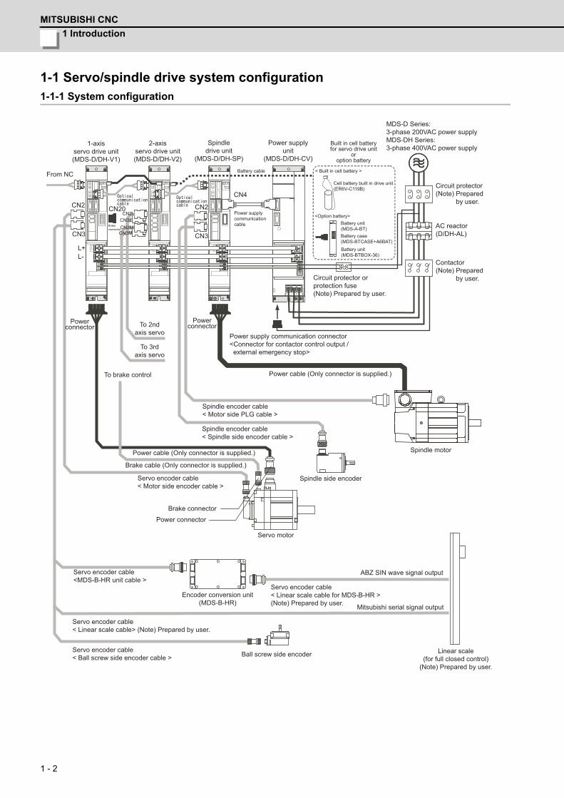
1-1 Servo/spindle drive system configuration1-1-1 System configuration
CN2LCN3LCN2MCN3M
MDS-D Series:3-phase 200VAC power supplyMDS-DH Series:3-phase 400VAC power supply
From NC
1-axis servo drive unit(MDS-D/DH-V1)
2-axis servo drive unit(MDS-D/DH-V2)
Spindle drive unit
(MDS-D/DH-SP)
Power supplyunit
(MDS-D/DH-CV)
Built in cell battery for servo drive unit
oroption battery
CN2 CN2
CN4
CN3CN3
CN20
Brake connector
Battery cable
Power supply communication cable
L+L-
Power connector
To 3rd axis servo
Spindle encoder cable< Motor side PLG cable >
Spindle encoder cable< Spindle side encoder cable >
Power cable (Only connector is supplied.)
Brake cable (Only connector is supplied.)
Servo encoder cable< Motor side encoder cable >
Brake connector
Power connector
Servo motor
Spindle side encoder
Servo encoder cable<MDS-B-HR unit cable >
Servo encoder cable< Linear scale cable> (Note) Prepared by user.
Servo encoder cable< Ball screw side encoder cable > Ball screw side encoder
Encoder conversion unit(MDS-B-HR)
Linear scale(for full closed control)
(Note) Prepared by user.
Servo encoder cable< Linear scale cable for MDS-B-HR >(Note) Prepared by user.
Spindle motor
Power cable (Only connector is supplied.)
Power supply communication connector<Connector for contactor control output / external emergency stop>
Circuit protector orprotection fuse(Note) Prepared by user.
Contactor(Note) Prepared by user.
AC reactor(D/DH-AL)
Circuit protector(Note) Prepared by user.
< Built in cell battery >
<Option battery>
Cell battery built in drive unit(ER6V-C119B)
Battery unit(MDS-A-BT)Battery case(MDS-BTCASE+A6BAT)Battery unit(MDS-BTBOX-36)
Power connector
To brake control
To 2nd axis servo
ABZ SIN wave signal output
Mitsubishi serial signal output
MDS-D/DH Series Specifications Manual
1-2 Explanation of type
1 - 3
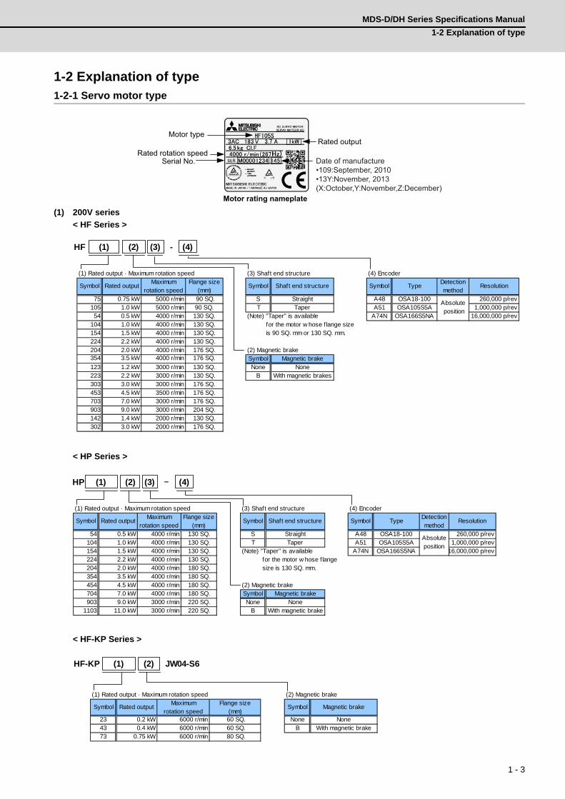
1-2 Explanation of type1-2-1 Servo motor type
(1) 200V series
< HF Series >
< HP Series >
< HF-KP Series >
Serial No. Rated rotation speed
Motor type Rated output
Motor rating nameplate
Date of manufacture•109:September, 2010•13Y:November, 2013(X:October,Y:November,Z:December)
(1) Rated output · Maximum rotation speed (3) Shaft end structure (4) Encoder
Symbol Rated outputMaximum
rotation speedFlange size
(mm)Symbol Shaft end structure Symbol Type
Detectionmethod
Resolution
75 0.75 kW 5000 r/min 90 SQ. S Straight A48 OSA18-100 260,000 p/rev105 1.0 kW 5000 r/min 90 SQ. T Taper A51 OSA105S5A 1,000,000 p/rev54 0.5 kW 4000 r/min 130 SQ. (Note) "Taper" is available A74N OSA166S5NA 16,000,000 p/rev
104 1.0 kW 4000 r/min 130 SQ. for the motor w hose f lange size154 1.5 kW 4000 r/min 130 SQ. is 90 SQ. mm or 130 SQ. mm.224 2.2 kW 4000 r/min 130 SQ.204 2.0 kW 4000 r/min 176 SQ. (2) Magnetic brake354 3.5 kW 4000 r/min 176 SQ. Symbol Magnetic brake123 1.2 kW 3000 r/min 130 SQ. None None223 2.2 kW 3000 r/min 130 SQ. B With magnetic brakes303 3.0 kW 3000 r/min 176 SQ.453 4.5 kW 3500 r/min 176 SQ.703 7.0 kW 3000 r/min 176 SQ.903 9.0 kW 3000 r/min 204 SQ.142 1.4 kW 2000 r/min 130 SQ.302 3.0 kW 2000 r/min 176 SQ.
Absolute position
HF (1) (2) (3) - (4)
(1) Rated output · Maximum rotation speed (3) Shaft end structure (4) Encoder
Symbol Rated outputMaximum
rotation speedFlange size
(mm)Symbol Shaft end structure Symbol Type
Detectionmethod
Resolution
54 0.5 kW 4000 r/min 130 SQ. S Straight A48 OSA18-100 260,000 p/rev104 1.0 kW 4000 r/min 130 SQ. T Taper A51 OSA105S5A 1,000,000 p/rev154 1.5 kW 4000 r/min 130 SQ. (Note) "Taper" is available A74N OSA166S5NA 16,000,000 p/rev224 2.2 kW 4000 r/min 130 SQ. for the motor w hose f lange204 2.0 kW 4000 r/min 180 SQ. size is 130 SQ. mm.354 3.5 kW 4000 r/min 180 SQ.454 4.5 kW 4000 r/min 180 SQ. (2) Magnetic brake704 7.0 kW 4000 r/min 180 SQ. Symbol Magnetic brake903 9.0 kW 3000 r/min 220 SQ. None None
1103 11.0 kW 3000 r/min 220 SQ. B With magnetic brake
Absoluteposition
HP (1) (2) (3) - (4)
(1) Rated output · Maximum rotation speed (2) Magnetic brake
Symbol Rated outputMaximum
rotation speedFlange size
(mm)Symbol Magnetic brake
23 0.2 kW 6000 r/min 60 SQ. None None43 0.4 kW 6000 r/min 60 SQ. B With magnetic brake73 0.75 kW 6000 r/min 80 SQ.
HF-KP (1) JW04-S6(2)
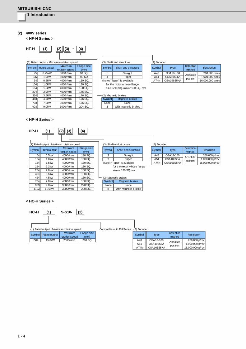
1 Introduction
MITSUBISHI CNC
1 - 4
(2) 400V series
< HF-H Series >
< HP-H Series >
< HC-H Series >
(1) Rated output · Maximum rotation speed (3) Shaft end structure (4) Encoder
Symbol Rated outputMaximum
rotation speedFlange size
(mm)Symbol Shaft end structure Symbol Type
Detectionmethod
Resolution
75 0.75kW 5000r/min 90 SQ. S Straight A48 OSA18-100 260,000 p/rev105 1.0kW 5000r/min 90 SQ. T Taper A51 OSA105S5A 1,000,000 p/rev54 0.5kW 4000r/min 130 SQ. (Note) "Taper" is available A74N OSA166S5NA 16,000,000 p/rev
104 1.0kW 4000r/min 130 SQ. for the motor w hose flange154 1.5kW 4000r/min 130 SQ. size is 90 SQ. mm or 130 SQ. mm.204 2.0kW 4000r/min 176 SQ.354 3.5kW 4000r/min 176 SQ. (2) Magnetic brakes453 4.5kW 3500r/min 176 SQ. Symbol Magnetic brakes
703 7.0kW 3000r/min 176 SQ. None None903 9.0kW 3000r/min 204 SQ. B With magnetic brakes
Absoluteposition
HF-H (1) (2) (3) - (4)
(1) Rated output · Maximum rotation speed (3) Shaft end structure (4) Encoder
Symbol Rated output Maximum
rotation speed Flange size
(mm)Symbol Shaft end structure Symbol Type
Detectionmethod
Resolution
54 0.5kW 4000r/min 130 SQ. S Straight A48 OSA18-100 260,000 p/rev104 1.0kW 4000r/min 130 SQ. T Taper A51 OSA105S5A 1,000,000 p/rev154 1.5kW 4000r/min 130 SQ. (Note) "Taper" is available A74N OSA166S5NA 16,000,000 p/rev224 2.2kW 4000r/min 130 SQ. for the motor w hose f lange204 2.0kW 4000r/min 180 SQ. size is 130 SQ.mm.354 3.5kW 4000r/min 180 SQ.454 4.5kW 4000r/min 180 SQ. (2) Magnetic brakes704 7.0kW 4000r/min 180 SQ. Symbol Magnetic brakes
903 9.0kW 3000r/min 220 SQ. None None1103 11.0kW 3000r/min 220 SQ. B With magnetic brakes
Absoluteposition
HP-H (1) (2) (3) - (4)
(1) Rated output · Maximum rotation speed Compatible w ith DH Series (2) Encoder
Symbol Rated outputMaximum
rotation speedFlange size
(mm)Symbol Type
Detectionmethod
Resolution
1502 15.0kW 2500r/min 280 SQ. A48 OSA18-100 260,000 p/revA51 OSA105S5A 1,000,000 p/revA74N OSA166S5NA 16,000,000 p/rev
Absoluteposition
HC-H (1) (2)S-S10-
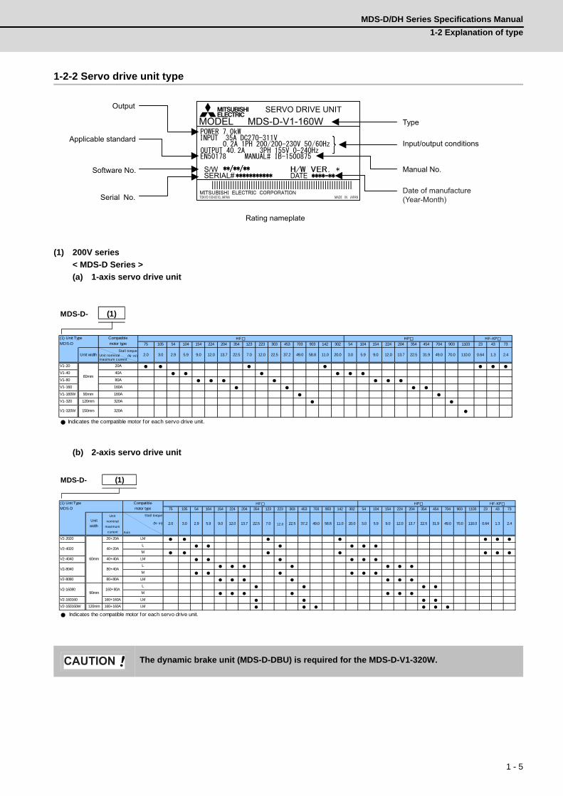
MDS-D/DH Series Specifications Manual
1-2 Explanation of type
1 - 5
1-2-2 Servo drive unit type
(1) 200V series
< MDS-D Series >
(a) 1-axis servo drive unit
(b) 2-axis servo drive unit
The dynamic brake unit (MDS-D-DBU) is required for the MDS-D-V1-320W.
TOKYO 100-8310, JAPAN MADE IN JAPAN
MODELSERVO DRIVE UNIT
MDS-D-V1-160W
|||||||||||||||||||||||||||||||||||||||||||||||||||||||||||||
S/WSERIAL# DATE
Type
Input/output conditions
Software No.
Output
Applicable standard
Serial No.
Manual No.
Rating nameplate
Date of manufacture(Year-Month)
MDS-D-
75 105 54 104 154 224 204 354 123 223 303 453 703 903 142 302 54 104 154 224 204 354 454 704 903 1103 23 43 73
Stall torqueUnit nominal (N・m)maximum current
V1-20
V1-40
V1-80
V1-160
V1-160W 90mm
V1-320 120mm
V1-320W 150mm
Indicates the compatible motor for each servo drive unit.
2.4
HF-KP
0.64 1.3
160A
320A
49.0 70.0 110.03.0
HPCompatiblemotor type
Unit width
320A
(1)
20A
40A
80A
31.99.0
60mm
(1) Unit TypeMDS-D
160A
2.0 3.0 9.0 13.7 22.5 37.2 13.75.9 12.049.0 58.8 22.522.57.0 12.0
HF
11.0 20.02.9 5.9 12.0
MDS-D-
75 105 54 104 154 224 204 354 123 223 303 453 703 903 142 302 54 104 154 224 204 354 454 704 903 1103 23 43 73
Stall torque
(N・m)
Axis
V2-2020 20+20A
V2-4040 40+40A
V2-8080 80+80A
V2-160160 160+160A
V2-160160W 120mm 160+160A
Indicates the compatible motor for each servo drive unit.
31.9
LM
0.64 1.3 2.4
80+40A
49.0 70.0 110.09.0 12.09.0
160+80A
40+20A
L
M
L
M
L
M
13.7 22.5
V2-8040
V2-16080
60mm
90mm
V2-4020
HP
(1)
49.0 20.0 3.0
Compatiblemotor type
2.9 5.9 13.7 22.5 5.911.0
(1) Unit TypeMDS-D
HF
2.0 3.0 37.2
Unit
nominal
maximum
current
Unitwidth
HF-KP
LM
58.812.0 7.0 12.0 22.5
LM
LM
LM
CAUTION
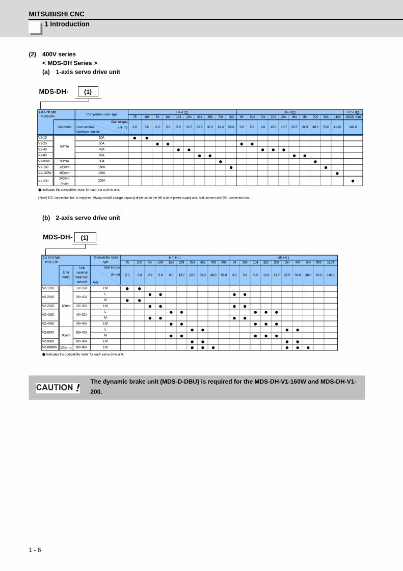
1 Introduction
MITSUBISHI CNC
1 - 6
(2) 400V series
< MDS-DH Series >
(a) 1-axis servo drive unit
(b) 2-axis servo drive unit
The dynamic brake unit (MDS-D-DBU) is required for the MDS-DH-V1-160W and MDS-DH-V1-
200.
MDS-DH-
HC-H
75 105 54 104 154 204 354 453 703 903 54 104 154 224 204 354 454 704 903 1103 1502S-S10
Stall torque
Unit nominal (N・m)maximum current
V1-10
V1-20
V1-40
V1-80
V1-80W 90mm
V1-160 120mm
V1-160W 150mm
V1-200240mm
(Note)
Indicates the compatible motor for each servo drive unit.
(Note) DC connection bar is required. Always install a large capacity drive unit in the left side of power supply unit, and connect with DC connection bar.
80A
160A
160A
200A
146.0
10A
20A
40A
31.9 49.0 70.0 110.09.0 12.049.0 58.8 3.0 5.9
60mm
(1) Unit type MDS-DH
HF-H
80A
2.0 3.0 2.9 5.9
HP-H Compatible motor type
Unit width 9.0 13.7 22.5 37.2 13.7 22.5
(1)
MDS-DH-
75 105 54 104 154 204 354 453 703 903 54 104 154 224 204 354 454 704 903 1103
Stall torque
(N・m)
Axis
V2-1010 10+10A
V2-2020 20+20A
V2-4040 40+40A
V2-8080 80+80A
V2-8080W 120mm 80+80A
Indicates the compatible motor for each servo drive unit.
LM
40+20A
80+40A
20+10A
L
M
L
M
L
M
LM
V2-4020
V2-8040
60mm
90mm
V2-2010
LM
LM
LM
HP-H Compatible motortype
Unit nominalmaximumcurrent
9.0 13.7 22.5 37.2 13.7 22.5
(1) Unit type MDS-DH
HF-H
2.0 3.0 2.9 5.9Unitwidth
49.0 70.0 110.09.0 12.0 31.958.8 3.0 5.9 49.0
(1)
CAUTION
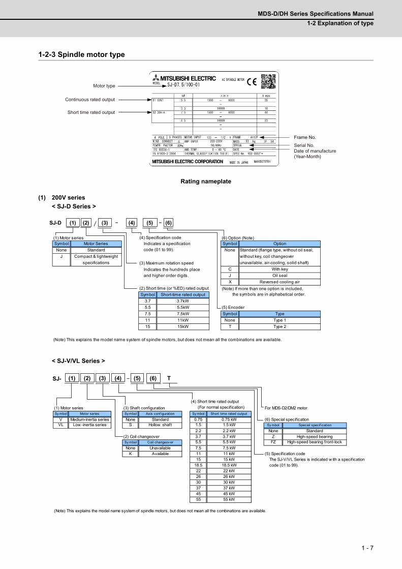
MDS-D/DH Series Specifications Manual
1-2 Explanation of type
1 - 7
1-2-3 Spindle motor type
Rating nameplate
(1) 200V series
< SJ-D Series >
< SJ-V/VL Series >
Date of manufacture(Year-Month)
Serial No.
Motor type
Continuous rated output
Short time rated output
Frame No.
(1) Motor series (4) Specification code (6) Option (Note)Symbol Motor Series Indicates a specification Symbol Option
None Standard code (01 to 99). None Standard (flange type, without oil seal,
J Compact & lightweight without key, coil changeover
specifications (3) Maximum rotation speed unavailable, air-cooling, solid shaft)
Indicates the hundreds place C With key
and higher order digits. J Oil seal
X Reversed cooling air
(2) Short time (or %ED) rated output (Note) If more than one option is included,
Symbol Short-time rated output the symbols are in alphabetical order.
3.7 3.7kW
5.5 5.5kW (5) Encoder
7.5 7.5kW Symbol Type
11 11kW None Type 1
15 15kW T Type 2
(Note) This explains the model name system of spindle motors, but does not mean all the combinations are available.
(1) (2) (4)(3)SJ-D / - (5) (6)-
(1) Motor series (3) Shaft configuration For MDS-D2/DM2 motorSy mbol Motor series Sy mbol Axis conf iguration Sy mbol Short time rated output
V Medium-inertia series None Standard 0.75 0.75 kW (6) Special specif icationVL Low -inertia series S Hollow shaft 1.5 1.5 kW Sy mbol Special specif ication
2.2 2.2 kW None Standard(2) Coil changeover 3.7 3.7 kW Z High-speed bearingSy mbol Coil changeov er 5.5 5.5 kW FZ High-speed bearing front-lock
None Unavailable 7.5 7.5 kWK Available 11 11 kW (5) Specif ication code
15 15 kW The SJ-V/VL Series is indicated w ith a specif ication 18.5 18.5 kW code (01 to 99).22 22 kW26 26 kW30 30 kW37 37 kW45 45 kW55 55 kW
(Note) This explains the model name system of spindle motors, but does not mean all the combinations are available.
(4) Short time rated output (For normal specif ication)
SJ- -(1) (6)(5) T(2) (4)(3)
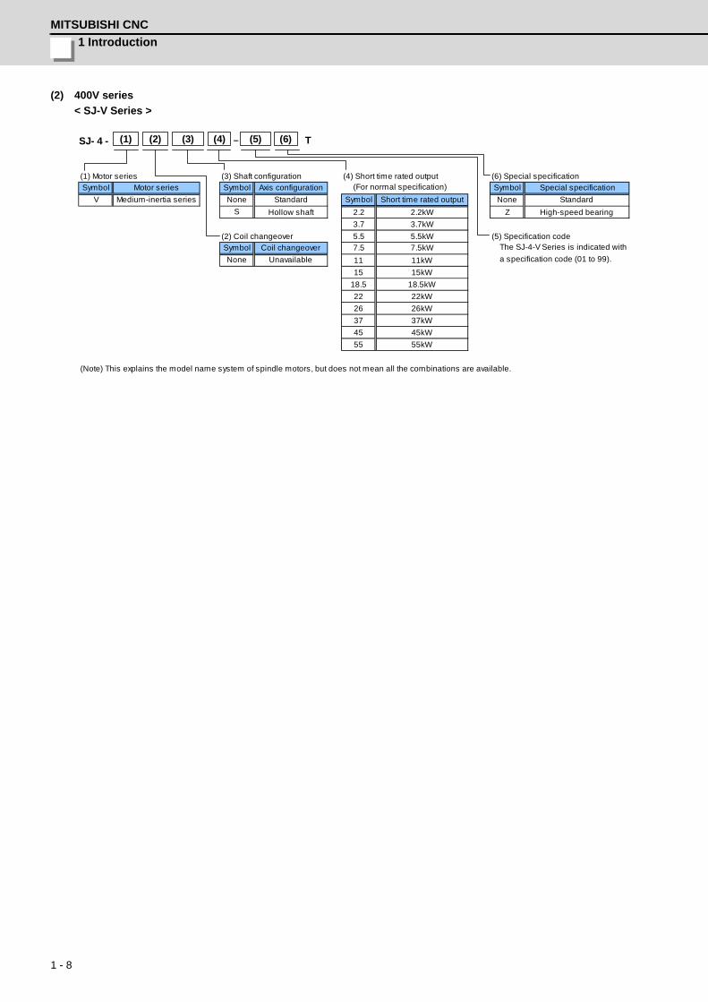
1 Introduction
MITSUBISHI CNC
1 - 8
(2) 400V series
< SJ-V Series >
(1) Motor series (3) Shaft configuration (4) Short time rated output (6) Special specification
Symbol Motor series Symbol Axis configuration Symbol Special specification
V Medium-inertia series None Standard Symbol Short time rated output None Standard
S Hollow shaft 2.2 2.2kW Z High-speed bearing
3.7 3.7kW
(2) Coil changeover 5.5 5.5kW (5) Specification code
Symbol Coil changeover 7.5 7.5kW The SJ-4-V Series is indicated with
None Unavailable 11 11kW a specification code (01 to 99).
15 15kW
18.5 18.5kW
22 22kW
26 26kW
37 37kW
45 45kW
55 55kW
(Note) This explains the model name system of spindle motors, but does not mean all the combinations are available.
(For normal specification)
SJ- 4 - -(1) (6)(5) T(2) (4)(3)
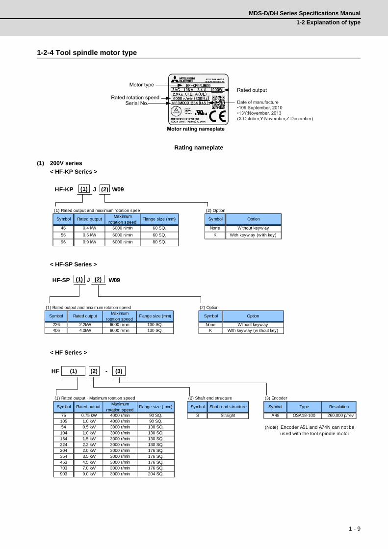
MDS-D/DH Series Specifications Manual
1-2 Explanation of type
1 - 9
1-2-4 Tool spindle motor type
Rating nameplate
(1) 200V series
< HF-KP Series >
< HF-SP Series >
< HF Series >
Serial No. Rated rotation speed
Motor type Rated output
Motor rating nameplate
Date of manufacture•109:September, 2010•13Y:November, 2013(X:October,Y:November,Z:December)
(1) Rated output and maximum rotation spee (2) Option
Symbol Rated outputMaximum
rotation speedFlange size (mm) Symbol Option
46 0.4 kW 6000 r/min 60 SQ. None Without keyw ay
56 0.5 kW 6000 r/min 60 SQ. K With keyw ay (w ith key)
96 0.9 kW 6000 r/min 80 SQ.
(1) (2) W09JHF-KP
(1) Rated output and maximum rotation speed (2) Option
Symbol Rated outputMaximum
rotation speedFlange size (mm) Symbol Option
226 2.2kW 6000 r/min 130 SQ. None Without keyw ay406 4.0kW 6000 r/min 130 SQ. K With keyw ay (w ithout key)
(1) (2) W09JHF-SP
(1) Rated output · Maximum rotation speed (2) Shaft end structure (3) Encoder
Symbol Rated outputMaximum
rotation speedFlange size ( mm) Symbol Shaft end structure Symbol Type Resolution
75 0.75 kW 4000 r/min 90 SQ. S Straight A48 OSA18-100 260,000 p/rev105 1.0 kW 4000 r/min 90 SQ.54 0.5 kW 3000 r/min 130 SQ.104 1.0 kW 3000 r/min 130 SQ.154 1.5 kW 3000 r/min 130 SQ.224 2.2 kW 3000 r/min 130 SQ.204 2.0 kW 3000 r/min 176 SQ.354 3.5 kW 3000 r/min 176 SQ.453 4.5 kW 3000 r/min 176 SQ.703 7.0 kW 3000 r/min 176 SQ.903 9.0 kW 3000 r/min 204 SQ.
(Note) Encoder A51 and A74N can not be used with the tool spindle motor.
HF (1) (2) - (3)
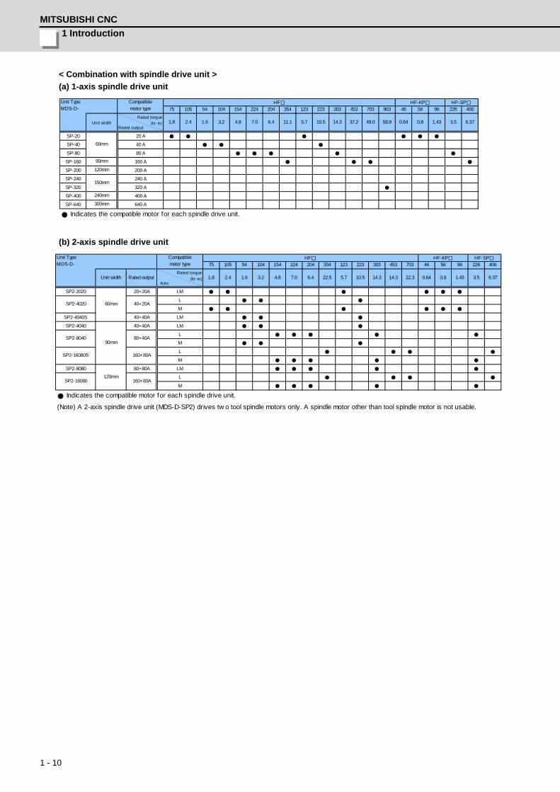
1 Introduction
MITSUBISHI CNC
1 - 10
< Combination with spindle drive unit >
(a) 1-axis spindle drive unit
(b) 2-axis spindle drive unit
75 105 54 104 154 224 204 354 123 223 303 453 703 903 46 56 96 226 406
Rated torque
(N・m)Rated output
SP-20
SP-40
SP-80
SP-160 90mm
SP-200 120mm
SP-240
SP-320
SP-400 240mm
SP-640 300mm
Indicates the compatible motor for each spindle drive unit.
HF
1.6 3.2 7.0 49.0 58.810.5 0.8
Unit TypeMDS-D-
160 A
1.8 2.4
60mm
20 A
6.4Unit width 11.1 37.214.35.7
HF-SP
150mm
80 A
4.8
HF-KP
0.64
400 A
Compatiblemotor type
3.5 6.371.43
640 A
200 A
240 A
320 A
40 A
75 105 54 104 154 224 204 354 123 223 303 453 703 46 56 96 226 406
Rated torque
(N・m)Axis
SP2-2020 20+20A
M
SP2-4040S 40+40A
SP2-4040 40+40A
M
M
SP2-8080 80+80A
M
Indicates the compatible motor for each spindle drive unit.
(Note) A 2-axis spindle drive unit (MDS-D-SP2) drives tw o tool spindle motors only. A spindle motor other than tool spindle motor is not usable.
120mm
LM
SP2-16080 160+80AL
90mm
LM
SP2-8040 80+40A
SP2-4020 40+20AL
LM
L
SP2-16080S 160+80AL
3.5 6.371.433.2 7.0
60mm
LM
Rated output
HF-KP
0.64 0.8
Unit TypeMDS-D-
1.8 2.4 22.310.5
HF
1.6
HF-SPCompatiblemotor type
Unit width 4.8 6.4 22.5 14.314.35.7
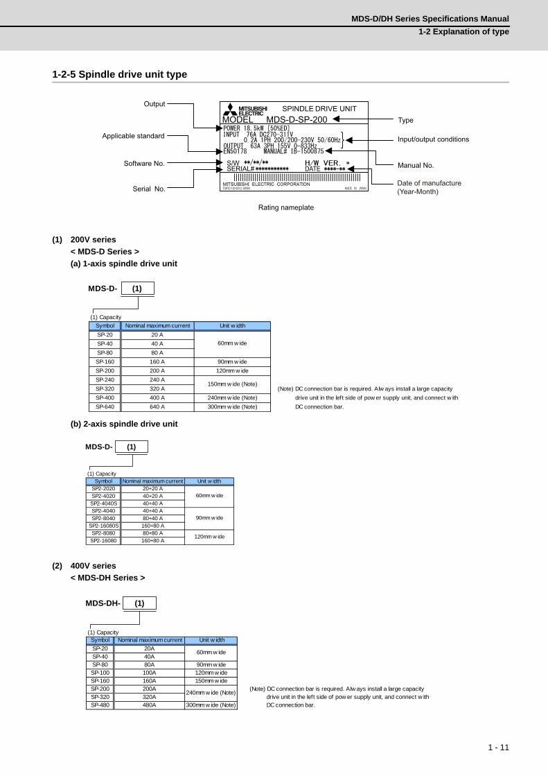
MDS-D/DH Series Specifications Manual
1-2 Explanation of type
1 - 11
1-2-5 Spindle drive unit type
(1) 200V series
< MDS-D Series >
(a) 1-axis spindle drive unit
(b) 2-axis spindle drive unit
(2) 400V series
< MDS-DH Series >
TOKYO 100-8310, JAPAN MADE IN JAPAN
MODEL
|||||||||||||||||||||||||||||||||||||||||||||||||||||||||||||
SPINDLE DRIVE UNITMDS-D-SP-200
S/WSERIAL# DATE
Type
Output
Serial No.
Input/output conditions
Software No.
Applicable standard
Manual No.
Rating nameplate
Date of manufacture(Year-Month)
(1) Capacity
Symbol Nominal maximum current Unit w idth
SP-20 20 A
SP-40 40 A
SP-80 80 A
SP-160 160 A 90mm w ide
SP-200 200 A 120mm w ide
SP-240 240 A
SP-320 320 A (Note) DC connection bar is required. Alw ays install a large capacity
SP-400 400 A 240mm w ide (Note) drive unit in the left side of pow er supply unit, and connect w ith
SP-640 640 A 300mm w ide (Note) DC connection bar.
60mm w ide
150mm w ide (Note)
MDS-D- (1)
(1) CapacitySymbol Nominal maximum current Unit w idth
SP2-2020 20+20 ASP2-4020 40+20 ASP2-4040S 40+40 ASP2-4040 40+40 ASP2-8040 80+40 A
SP2-16080S 160+80 ASP2-8080 80+80 ASP2-16080 160+80 A
120mm w ide
60mm w ide
90mm w ide
MDS-D- (1)
(1) CapacitySymbol Nominal maximum current Unit w idth
SP-20 20ASP-40 40ASP-80 80A 90mm w ideSP-100 100A 120mm w ideSP-160 160A 150mm w ideSP-200 200A (Note) DC connection bar is required. Alw ays install a large capacitySP-320 320A drive unit in the left side of pow er supply unit, and connect w ithSP-480 480A 300mm w ide (Note) DC connection bar.
240mm w ide (Note)
60mm w ide
MDS-DH- (1)

1 Introduction
MITSUBISHI CNC
1 - 12
1-2-6 Power supply unit type
(1) 200V series
< MDS-D Series >
(2) 400V series
< MDS-DH Series >
TOKYO 100-8310, JAPAN MADE IN JAPAN
MODEL
|||||||||||||||||||||||||||||||||||||||||||||||||||||||||||||
POWER SUPPLY UNITMDS-D-CV-370
S/WSERIAL# DATE
Type
Input/output conditions
Software No.
Output
Applicable standard
Serial No.
Manual No.
Rating nameplate
Date of manufacture(Year-Month)
(1) TypeMDS-D-
30-minuterated output
Continuousrated output
Unit w idth
CV-37 3.7kW 2.2kW S-T12-AC200V NF63-CW3P-20ACV-75 7.5kW 5.5kW NF63-CW3P-40ACV-110 11.0kW 7.5kW D-AL-11K NF63-CW3P-50ACV-185 18.5kW 15.0kW D-AL-18.5K S-T65-AC200V NF125-CW3P-100ACV-300 30.0kW 26.0kW D-AL-30K S-T80-AC200V NF250-CW3P-125ACV-370 37.0kW 30.0kW D-AL-37K NF250-CW3P-175ACV-450 45.0kW 37.0kW D-AL-45K NF250-CW3P-200ACV-550 55.0kW 45.0kW 300mm w ide (Note 2) D-AL-55K S-N180-AC200V NF250-CW3P-225A
(Note 1) This is an optional part, and must be prepared by the user.(Note 2) When connecting w ith a large capacity drive unit, DC connection bar is required. Alw ays install a large capacity drive unit in the left side of pow er supply unit, and connect w ith DC connection bar.
Pow er supply unit
Compatible AC reactorCompatible contactor
(Mitsubishi)(Note 1)
Compatiblecircuit protector
(Mitsubishi)(Note 1)
S-T35-AC200V
S-N150-AC200V
60mm w ide
90mm w ide
150mm w ide(Note 2)
D-AL-7.5K
MDS-D- (1)
(1) TypeMDS-DH-
30-minuterated output
Continuousrated output
Unit w idth
CV-37 3.7kW 2.2kW NF63-CW3P-10ACV-75 7.5kW 5.5kW NF63-CW3P-20A
CV-110 11.0kW 7.5kW DH-AL-11K S-T21-AC400V NF63-CW3P-30ACV-185 18.5kW 15.0kW DH-AL-18.5K S-T35-AC400V NF63-CW3P-40ACV-300 30.0kW 26.0kW DH-AL-30K S-T50-AC400V NF125-CW3P-75ACV-370 37.0kW 30.0kW DH-AL-37K NF125-CW3P-100ACV-450 45.0kW 37.0kW DH-AL-45K NF125-CW3P-100ACV-550 55.0kW 45.0kW DH-AL-55K S-T80-AC400V NF250-CW3P-125ACV-750 75.0kW 55.0kW DH-AL-75K S-N150-AC400V NF250-CW3P-200A
(Note 1) This is an optional part, and must be prepared by the user. (Note 2) When connecting w ith a large capacity drive unit, DC connection bar is required.Alw ays install a large capacity drive unit in the left side of pow er supply unit, and connect w ith DC connection bar.
90mm w ide
Compatiblecircuit protector
(Mitsubishi)(Note 1)
300mm w ide(Note 2)
Pow er supply unit
Compatible AC reactor Compatible contactor
(Mitsubishi)(Note 1)
S-T12-AC400V
S-T65-AC400V
DH-AL-7.5K
150mm w ide(Note 2)
MDS-DH- (1)
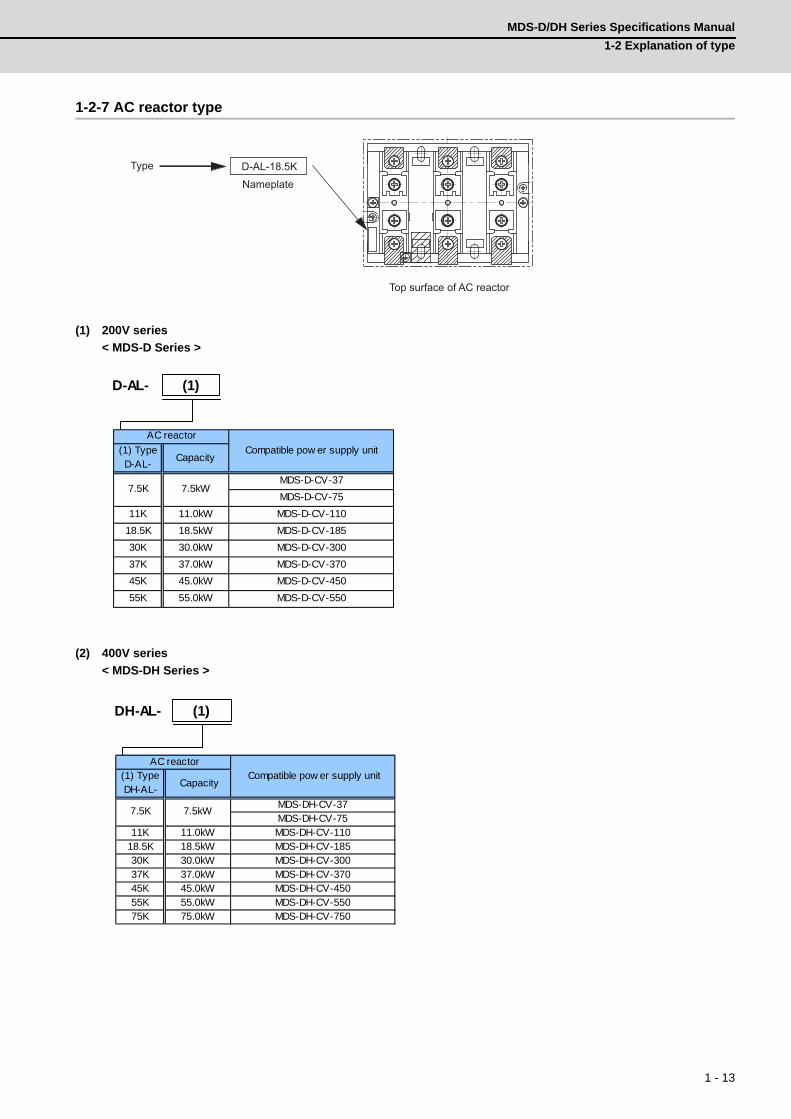
MDS-D/DH Series Specifications Manual
1-2 Explanation of type
1 - 13
1-2-7 AC reactor type
(1) 200V series
< MDS-D Series >
(2) 400V series
< MDS-DH Series >
Type
Nameplate
Top surface of AC reactor
D-AL-18.5K
(1) TypeD-AL-
Capacity
MDS-D-CV-37
MDS-D-CV-75
11K 11.0kW MDS-D-CV-110
18.5K 18.5kW MDS-D-CV-185
30K 30.0kW MDS-D-CV-300
37K 37.0kW MDS-D-CV-370
45K 45.0kW MDS-D-CV-450
55K 55.0kW MDS-D-CV-550
AC reactor
Compatible pow er supply unit
7.5kW7.5K
D-AL- (1)
(1) TypeDH-AL-
Capacity
MDS-DH-CV-37MDS-DH-CV-75
11K 11.0kW MDS-DH-CV-11018.5K 18.5kW MDS-DH-CV-18530K 30.0kW MDS-DH-CV-30037K 37.0kW MDS-DH-CV-37045K 45.0kW MDS-DH-CV-45055K 55.0kW MDS-DH-CV-55075K 75.0kW MDS-DH-CV-750
AC reactor Compatible pow er supply unit
7.5kW7.5K
DH-AL- (1)

1 Introduction
MITSUBISHI CNC
1 - 14

2 - 1
2
Specifications
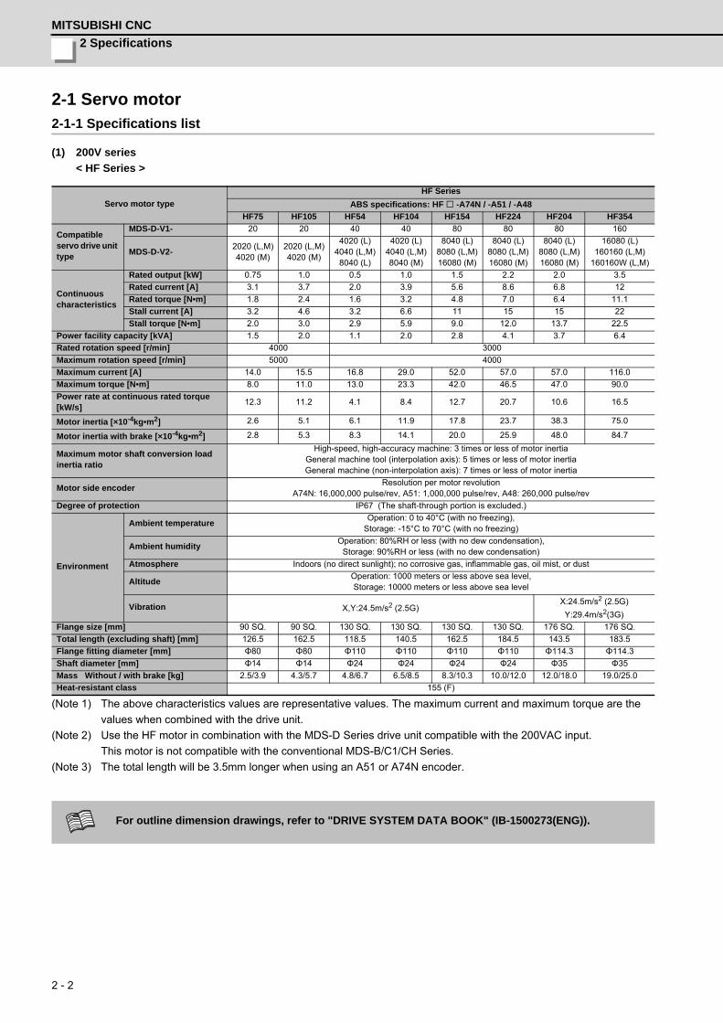
2 Specifications
MITSUBISHI CNC
2 - 2
2-1 Servo motor2-1-1 Specifications list
(1) 200V series
< HF Series >
(Note 1) The above characteristics values are representative values. The maximum current and maximum torque are the
values when combined with the drive unit.
(Note 2) Use the HF motor in combination with the MDS-D Series drive unit compatible with the 200VAC input.
This motor is not compatible with the conventional MDS-B/C1/CH Series.
(Note 3) The total length will be 3.5mm longer when using an A51 or A74N encoder.
Servo motor type
HF Series
ABS specifications: HF -A74N / -A51 / -A48
HF75 HF105 HF54 HF104 HF154 HF224 HF204 HF354
Compatible servo drive unit type
MDS-D-V1- 20 20 40 40 80 80 80 160
MDS-D-V2-2020 (L,M)4020 (M)
2020 (L,M)4020 (M)
4020 (L)4040 (L,M)
8040 (L)
4020 (L)4040 (L,M)8040 (M)
8040 (L)8080 (L,M)16080 (M)
8040 (L)8080 (L,M)16080 (M)
8040 (L)8080 (L,M)16080 (M)
16080 (L)160160 (L,M)
160160W (L,M)
Continuous characteristics
Rated output [kW] 0.75 1.0 0.5 1.0 1.5 2.2 2.0 3.5
Rated current [A] 3.1 3.7 2.0 3.9 5.6 8.6 6.8 12
Rated torque [N•m] 1.8 2.4 1.6 3.2 4.8 7.0 6.4 11.1
Stall current [A] 3.2 4.6 3.2 6.6 11 15 15 22
Stall torque [N•m] 2.0 3.0 2.9 5.9 9.0 12.0 13.7 22.5
Power facility capacity [kVA] 1.5 2.0 1.1 2.0 2.8 4.1 3.7 6.4
Rated rotation speed [r/min] 4000 3000
Maximum rotation speed [r/min] 5000 4000
Maximum current [A] 14.0 15.5 16.8 29.0 52.0 57.0 57.0 116.0
Maximum torque [N•m] 8.0 11.0 13.0 23.3 42.0 46.5 47.0 90.0
Power rate at continuous rated torque [kW/s]
12.3 11.2 4.1 8.4 12.7 20.7 10.6 16.5
Motor inertia [×10-4kg•m2] 2.6 5.1 6.1 11.9 17.8 23.7 38.3 75.0
Motor inertia with brake [×10-4kg•m2] 2.8 5.3 8.3 14.1 20.0 25.9 48.0 84.7
Maximum motor shaft conversion load inertia ratio
High-speed, high-accuracy machine: 3 times or less of motor inertiaGeneral machine tool (interpolation axis): 5 times or less of motor inertiaGeneral machine (non-interpolation axis): 7 times or less of motor inertia
Motor side encoderResolution per motor revolution
A74N: 16,000,000 pulse/rev, A51: 1,000,000 pulse/rev, A48: 260,000 pulse/rev
Degree of protection IP67 (The shaft-through portion is excluded.)
Environment
Ambient temperatureOperation: 0 to 40°C (with no freezing),
Storage: -15°C to 70°C (with no freezing)
Ambient humidityOperation: 80%RH or less (with no dew condensation),
Storage: 90%RH or less (with no dew condensation)
Atmosphere Indoors (no direct sunlight); no corrosive gas, inflammable gas, oil mist, or dust
AltitudeOperation: 1000 meters or less above sea level,Storage: 10000 meters or less above sea level
Vibration X,Y:24.5m/s2 (2.5G)X:24.5m/s2 (2.5G)
Y:29.4m/s2(3G)
Flange size [mm] 90 SQ. 90 SQ. 130 SQ. 130 SQ. 130 SQ. 130 SQ. 176 SQ. 176 SQ.
Total length (excluding shaft) [mm] 126.5 162.5 118.5 140.5 162.5 184.5 143.5 183.5
Flange fitting diameter [mm] Φ80 Φ80 Φ110 Φ110 Φ110 Φ110 Φ114.3 Φ114.3
Shaft diameter [mm] Φ14 Φ14 Φ24 Φ24 Φ24 Φ24 Φ35 Φ35
Mass Without / with brake [kg] 2.5/3.9 4.3/5.7 4.8/6.7 6.5/8.5 8.3/10.3 10.0/12.0 12.0/18.0 19.0/25.0
Heat-resistant class 155 (F)
For outline dimension drawings, refer to "DRIVE SYSTEM DATA BOOK" (IB-1500273(ENG)).
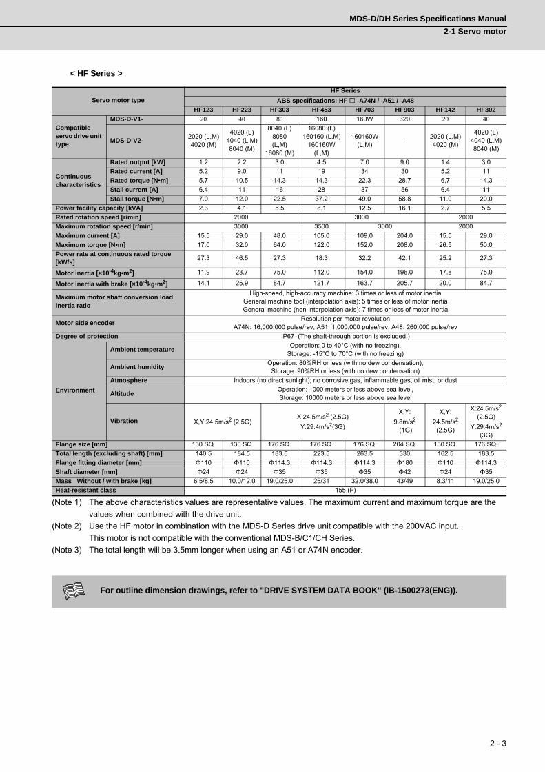
MDS-D/DH Series Specifications Manual
2-1 Servo motor
2 - 3
< HF Series >
(Note 1) The above characteristics values are representative values. The maximum current and maximum torque are the
values when combined with the drive unit.
(Note 2) Use the HF motor in combination with the MDS-D Series drive unit compatible with the 200VAC input.
This motor is not compatible with the conventional MDS-B/C1/CH Series.
(Note 3) The total length will be 3.5mm longer when using an A51 or A74N encoder.
Servo motor type
HF Series
ABS specifications: HF -A74N / -A51 / -A48
HF123 HF223 HF303 HF453 HF703 HF903 HF142 HF302
Compatible servo drive unit type
MDS-D-V1- 20 40 80 160 160W 320 20 40
MDS-D-V2-2020 (L,M)4020 (M)
4020 (L)4040 (L,M)8040 (M)
8040 (L)8080 (L,M)
16080 (M)
16080 (L)160160 (L,M)
160160W (L,M)
160160W (L,M)
-2020 (L,M)4020 (M)
4020 (L)4040 (L,M)8040 (M)
Continuous characteristics
Rated output [kW] 1.2 2.2 3.0 4.5 7.0 9.0 1.4 3.0
Rated current [A] 5.2 9.0 11 19 34 30 5.2 11
Rated torque [N•m] 5.7 10.5 14.3 14.3 22.3 28.7 6.7 14.3
Stall current [A] 6.4 11 16 28 37 56 6.4 11
Stall torque [N•m] 7.0 12.0 22.5 37.2 49.0 58.8 11.0 20.0
Power facility capacity [kVA] 2.3 4.1 5.5 8.1 12.5 16.1 2.7 5.5
Rated rotation speed [r/min] 2000 3000 2000
Maximum rotation speed [r/min] 3000 3500 3000 2000
Maximum current [A] 15.5 29.0 48.0 105.0 109.0 204.0 15.5 29.0
Maximum torque [N•m] 17.0 32.0 64.0 122.0 152.0 208.0 26.5 50.0
Power rate at continuous rated torque [kW/s]
27.3 46.5 27.3 18.3 32.2 42.1 25.2 27.3
Motor inertia [×10-4kg•m2] 11.9 23.7 75.0 112.0 154.0 196.0 17.8 75.0
Motor inertia with brake [×10-4kg•m2] 14.1 25.9 84.7 121.7 163.7 205.7 20.0 84.7
Maximum motor shaft conversion load inertia ratio
High-speed, high-accuracy machine: 3 times or less of motor inertiaGeneral machine tool (interpolation axis): 5 times or less of motor inertiaGeneral machine (non-interpolation axis): 7 times or less of motor inertia
Motor side encoderResolution per motor revolution
A74N: 16,000,000 pulse/rev, A51: 1,000,000 pulse/rev, A48: 260,000 pulse/rev
Degree of protection IP67 (The shaft-through portion is excluded.)
Environment
Ambient temperatureOperation: 0 to 40°C (with no freezing),
Storage: -15°C to 70°C (with no freezing)
Ambient humidityOperation: 80%RH or less (with no dew condensation),
Storage: 90%RH or less (with no dew condensation)
Atmosphere Indoors (no direct sunlight); no corrosive gas, inflammable gas, oil mist, or dust
AltitudeOperation: 1000 meters or less above sea level,Storage: 10000 meters or less above sea level
Vibration X,Y:24.5m/s2 (2.5G)X:24.5m/s2 (2.5G)
Y:29.4m/s2(3G)
X,Y:
9.8m/s2
(1G)
X,Y:
24.5m/s2 (2.5G)
X:24.5m/s2 (2.5G)
Y:29.4m/s2
(3G)
Flange size [mm] 130 SQ. 130 SQ. 176 SQ. 176 SQ. 176 SQ. 204 SQ. 130 SQ. 176 SQ.
Total length (excluding shaft) [mm] 140.5 184.5 183.5 223.5 263.5 330 162.5 183.5
Flange fitting diameter [mm] Φ110 Φ110 Φ114.3 Φ114.3 Φ114.3 Φ180 Φ110 Φ114.3
Shaft diameter [mm] Φ24 Φ24 Φ35 Φ35 Φ35 Φ42 Φ24 Φ35
Mass Without / with brake [kg] 6.5/8.5 10.0/12.0 19.0/25.0 25/31 32.0/38.0 43/49 8.3/11 19.0/25.0
Heat-resistant class 155 (F)
For outline dimension drawings, refer to "DRIVE SYSTEM DATA BOOK" (IB-1500273(ENG)).
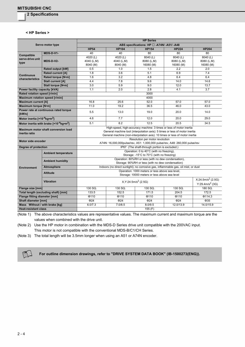
2 Specifications
MITSUBISHI CNC
2 - 4
< HP Series >
(Note 1) The above characteristics values are representative values. The maximum current and maximum torque are the
values when combined with the drive unit.
(Note 2) Use the HP motor in combination with the MDS-D Series drive unit compatible with the 200VAC input.
This motor is not compatible with the conventional MDS-B/C1/CH Series.
(Note 3) The total length will be 3.5mm longer when using an A51 or A74N encoder.
Servo motor type
HP Series
ABS specifications: HP -A74N/ -A51/ -A48
HP54 HP104 HP154 HP224 HP204
Compatible servo drive unit type
MDS-D-V1- 40 40 80 80 80
MDS-D-V2-4020 (L)
4040 (L,M)8040 (M)
4020 (L)4040 (L,M)8040 (M)
8040 (L)8080 (L,M)16080 (M)
8040 (L)8080 (L,M)16080 (M)
8040 (L)8080 (L,M)16080 (M)
Continuous characteristics
Rated output [kW] 0.5 1.0 1.5 2.2 2.0
Rated current [A] 1.8 3.6 5.1 6.9 7.4
Rated torque [N•m] 1.6 3.2 4.8 6.4 6.4
Stall current [A] 4.4 7.8 9.6 14.0 14.6
Stall torque [N•m] 3.0 5.9 9.0 12.0 13.7
Power facility capacity [kVA] 1.1 2.0 2.8 4.1 3.7
Rated rotation speed [r/min] 3000
Maximum rotation speed [r/min] 4000
Maximum current [A] 16.8 25.6 52.0 57.0 57.0
Maximum torque [N•m] 11.0 19.2 36.5 46.0 43.0
Power rate at continuous rated torque [kW/s]
5.5 13.0 19.0 20.0 14.0
Motor inertia [×10-4kg•m2] 4.6 7.7 12.0 20.0 29.0
Motor inertia with brake [×10-4kg•m2] 5.1 8.2 12.5 20.5 34.5
Maximum motor shaft conversion load inertia ratio
High-speed, high-accuracy machine: 3 times or less of motor inertiaGeneral machine tool (interpolation axis): 5 times or less of motor inertia
General machine (non-interpolation axis): 10 times or less of motor inertia
Motor side encoderResolution per motor revolution
A74N: 16,000,000pulse/rev, A51: 1,000,000 pulse/rev, A48: 260,000 pulse/rev
Degree of protection IP67 (The shaft-through portion is excluded.)
Environment
Ambient temperatureOperation: 0 to 40°C (with no freezing),
Storage: -15°C to 70°C (with no freezing)
Ambient humidityOperation: 80%RH or less (with no dew condensation),
Storage: 90%RH or less (with no dew condensation)
Atmosphere Indoors (no direct sunlight); no corrosive gas, inflammable gas, oil mist, or dust
AltitudeOperation: 1000 meters or less above sea level,Storage: 10000 meters or less above sea level
Vibration X,Y:24.5m/s2 (2.5G)X:24.5m/s2 (2.5G)
Y:29.4m/s2 (3G)
Flange size [mm] 130 SQ. 130 SQ. 130 SQ. 130 SQ. 180 SQ.
Total length (excluding shaft) [mm] 133.5 152.5 171.5 204.5 172.5
Flange fitting diameter [mm] Φ110 Φ110 Φ110 Φ110 Φ114.3
Shaft diameter [mm] Φ24 Φ24 Φ24 Φ24 Φ35
Mass Without / with brake [kg] 6.0/7.3 7.0/8.5 8.0/9.5 12.0/13.9 14.0/15.9
Heat-resistant class 155 (F)
For outline dimension drawings, refer to "DRIVE SYSTEM DATA BOOK" (IB-1500273(ENG)).

MDS-D/DH Series Specifications Manual
2-1 Servo motor
2 - 5
< HP Series >
(Note 1) The above characteristics values are representative values. The maximum current and maximum torque are the
values when combined with the drive unit.
(Note 2) Use the HP motor in combination with the MDS-D Series drive unit compatible with the 200VAC input.
This motor is not compatible with the conventional MDS-B/C1/CH Series.
(Note 3) The total length will be 3.5mm longer when using an A51 or A74N encoder.
Servo motor type
HP Series
ABS specifications: HP -A74N/ -A51/ -A48
HP354 HP454 HP704 HP903 HP1103
Compatible servo drive unit type
MDS-D-V1- 160 160 160W 320 320W
MDS-D-V2-16080 (L)
160160 (L,M)160160W (L,M)
16080 (L)160160 (L,M)
160160W (L,M)160160W (L,M) - -
Continuous characteristics
Rated output [kW] 3.5 4.5 7.0 9.0 11.0
Rated current [A] 14.5 12.8 17.2 21.6 24.6
Rated torque [N•m] 11.1 14.3 22.3 28.7 35.0
Stall current [A] 29.0 29.6 40.2 54.0 79.0
Stall torque [N•m] 22.5 31.9 49.0 70.0 110.0
Power facility capacity [kVA] 6.4 8.1 12.5 16.1 19.6
Rated rotation speed [r/min] 3000
Maximum rotation speed [r/min] 4000 3000
Maximum current [A] 116.0 116.0 116.0 172.0 212.0
Maximum torque [N•m] 66.0 95.0 120.0 170.0 260.0
Power rate at continuous rated torque [kW/s]
33.0 36.0 59.0 52.0 48.0
Motor inertia [×10-4kg•m2] 37.0 55.0 82.0 163.0 255.0
Motor inertia with brake [×10-4kg•m2] 42.5 60.5 87.5 187.0 279.0
Maximum motor shaft conversion load inertia ratio
High-speed, high-accuracy machine: 3 times or less of motor inertiaGeneral machine tool (interpolation axis): 5 times or less of motor inertia
General machine (non-interpolation axis): 10 times or less of motor inertia
Motor side encoderResolution per motor revolution
A74N: 16,000,000pulse/rev, A51: 1,000,000 pulse/rev, A48: 260,000 pulse/rev
Degree of protection IP67 (The shaft-through portion is excluded.)
Environment
Ambient temperatureOperation: 0 to 40°C (with no freezing),
Storage: -15°C to 70°C (with no freezing)
Ambient humidityOperation: 80%RH or less (with no dew condensation),
Storage: 90%RH or less (with no dew condensation)
Atmosphere Indoors (no direct sunlight); no corrosive gas, inflammable gas, oil mist, or dust
AltitudeOperation: 1000 meters or less above sea level,Storage: 10000 meters or less above sea level
Vibration X:24.5m/s2 (2.5G) Y:29.4m/s2(3G) X,Y:9.8m/s2 (1G)
Flange size [mm] 180 SQ. 180 SQ. 180 SQ. 220 SQ. 220 SQ.
Total length (excluding shaft) [mm] 195.5 225.5 305.5 346.5 419.5
Flange fitting diameter [mm] Φ114.3 Φ114.3 Φ114.3 Φ200 Φ200
Shaft diameter [mm] Φ35 Φ35 Φ35 Φ55 Φ55
Mass Without / with brake [kg] 17.0/22.0 21.0/26.0 37.0/43.0 51.0/61.4 74.0/84.4
Heat-resistant class 155 (F)
For outline dimension drawings, refer to "DRIVE SYSTEM DATA BOOK" (IB-1500273(ENG)).

2 Specifications
MITSUBISHI CNC
2 - 6
< HF-KP Series >
(Note 1) The above characteristics values are representative values. The maximum current and maximum torque are the
values when combined with the drive unit.
(Note 2) Use the HF-KP motor in combination with the MDS-D Series drive unit compatible with the 200VAC input. This
motor is not compatible with the conventional MDS-B/C1/CH Series.
Servo motor type
HF-KP Series
Absolute position standard
HF-KP23JW04-S6 HF-KP43JW04-S6 HF-KP73JW04-S6
Compatible servo drive unit type
MDS-D-V1- 20 20 20
MDS-D-V2-2020 (L,M)4020 (M)
2020 (L,M)4020 (M)
2020 (L,M)4020 (M)
Continuous characteristics
Rated output [kW] 0.2 0.4 0.75
Rated current [A] 1.4 2.9 5.2
Rated torque [N•m] 0.64 1.3 2.4
Stall current [A] 1.4 2.9 5.2
Stall torque [N•m] 0.64 1.3 2.4
Power facility capacity [kVA] 0.6 0.9 1.5
Rated rotation speed [r/min] 3000
Maximum rotation speed [r/min] 6000
Maximum current [A] 4.3 8.5 15.5
Maximum torque [N•m] 1.9 3.8 7.2
Power rate at continuous rated torque [kW/s]
16.9 38.6 39.9
Motor inertia [×10-4kg•m2] 0.23 0.42 1.43
Motor inertia with brake [×10-4kg•m2] 0.31 0.50 1.63
Maximum motor shaft conversion load inertia ratio
General machine (non-interpolation axis): 15 times or less of motor inertia
Motor side encoder Resolution per motor revolution: 260,000 pulse/rev
Degree of protection IP65 (The shaft-through portion is excluded.)
Environment
Ambient temperatureOperation: 0 to 40°C (with no freezing),
Storage: -15°C to 70°C (with no freezing)
Ambient humidityOperation: 80%RH or less (with no dew condensation),
Storage: 90%RH or less (with no dew condensation)
Atmosphere Indoors (no direct sunlight); no corrosive gas, inflammable gas, oil mist, or dust
AltitudeOperation: 1000 meters or less above sea level,Storage: 10000 meters or less above sea level
Vibration X,Y: 49m/s2 (5G)
Flange size [mm] 60 SQ. 60 SQ. 80 SQ.
Total length (excluding shaft) [mm] 98 119.9 134.2
Flange fitting diameter [mm] Φ50 Φ50 Φ70
Shaft diameter [mm] Φ14 Φ14 Φ19
Mass Without / with brake [kg] 1.2/1.8 1.7/2.3 2.9/4.1
Heat-resistant class 130 (B)
For outline dimension drawings, refer to "DRIVE SYSTEM DATA BOOK" (IB-1500273(ENG)).

MDS-D/DH Series Specifications Manual
2-1 Servo motor
2 - 7
(2) 400V series
< HF-H Series >
(Note 1) The above characteristics values are representative values. The maximum current and maximum torque are the
values when combined with the drive unit.
(Note 2) Use the HF-H motor in combination with the MDS-DH Series drive unit compatible with the 400VAC input. This
motor is not compatible with the conventional MDS-B/C1/CH Series.
(Note 3) The total length will be 3.5mm longer when using an A51 or A74N encoder.
Servo motor type
HF-H Series
ABS specifications: HF-H -A74N / -A51 / -A48
HF-H75 HF-H105 HF-H54 HF-H104 HF-H154
Compatible servo drive unit type
MDS-DH-V1 10 10 20 20 40
MDS-DH-V21010 (L,M)2010 (M)
1010 (L,M)2010 (M)
2010 (L)2020 (L,M)4020 (M)
2010 (L)2020 (L,M)4020 (M)
4020 (L)4040 (L,M)8040 (M)
Continuous characteristics
Rated output [kW] 0.75 1.0 0.5 1.0 1.5
Rated current [A] 1.5 1.8 1.1 2.0 2.7
Rated torque [N•m] 1.8 2.4 1.6 3.2 4.8
Stall current [A] 1.6 2.3 1.6 3.3 5.5
Stall torque [N•m] 2.0 3.0 2.9 5.9 9.0
Power facility capacity [kVA] 1.5 2.0 1.1 2.0 2.8
Rated rotation speed [r/min] 4000 3000
Maximum rotation speed [r/min] 5000 4000
Maximum current [A] 7.0 7.8 8.4 15.0 26.0
Maximum torque [N•m] 8.0 11.0 13.0 23.3 42.0
Power rate at continuous rated torque [kW/s]
12.3 11.2 4.1 8.4 12.7
Motor inertia [×10-4kg•m2] 2.6 5.1 6.1 11.9 17.8
Motor inertia with brake [×10-4kg•m2] 2.8 5.3 8.3 14.1 20.0
Maximum motor shaft conversion load inertia ratio
High-speed, high-accuracy machine: 3 times or less of motor inertiaGeneral machine tool (interpolation axis): 5 times or less of motor inertiaGeneral machine (non-interpolation axis): 7 times or less of motor inertia
Motor side encoderResolution per motor revolution
A74N: 16,000,000 pulse/rev, A51: 1,000,000 pulse/rev, A48: 260,000 pulse/rev
Degree of protection IP67 (The shaft-through portion is excluded.)
Environment
Ambient temperatureOperation: 0 to 40°C (with no freezing),
Storage: -15°C to 70°C (with no freezing)
Ambient humidityOperation: 80%RH or less (with no dew condensation),
Storage: 90%RH or less (with no dew condensation)
Atmosphere Indoors (no direct sunlight); no corrosive gas, inflammable gas, oil mist, or dust
AltitudeOperation: 1000 meters or less above sea level,Storage: 10000 meters or less above sea level
Vibration X,Y:24.5m/s2 (2.5G)
Flange size [mm] 90 SQ. 90 SQ. 130 SQ. 130 SQ. 130 SQ.
Total length (excluding shaft) [mm] 126.5 162.5 118.5 140.5 162.5
Flange fitting diameter [mm] Φ80 Φ80 Φ110 Φ110 Φ110
Shaft diameter [mm] Φ14 Φ14 Φ24 Φ24 Φ24
Mass Without / with brake [kg] 2.5/3.9 4.3/5.7 4.8/6.7 6.7/8.6 8.3/11
Heat-resistant class 155 (F)
For outline dimension drawings, refer to "DRIVE SYSTEM DATA BOOK" (IB-1500273(ENG)).
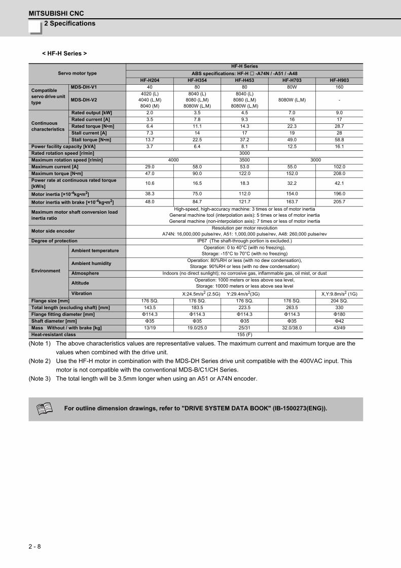
2 Specifications
MITSUBISHI CNC
2 - 8
< HF-H Series >
(Note 1) The above characteristics values are representative values. The maximum current and maximum torque are the
values when combined with the drive unit.
(Note 2) Use the HF-H motor in combination with the MDS-DH Series drive unit compatible with the 400VAC input. This
motor is not compatible with the conventional MDS-B/C1/CH Series.
(Note 3) The total length will be 3.5mm longer when using an A51 or A74N encoder.
Servo motor type
HF-H Series
ABS specifications: HF-H -A74N / -A51 / -A48
HF-H204 HF-H354 HF-H453 HF-H703 HF-H903
Compatible servo drive unit type
MDS-DH-V1 40 80 80 80W 160
MDS-DH-V24020 (L)
4040 (L,M)8040 (M)
8040 (L)8080 (L,M)
8080W (L,M)
8040 (L)8080 (L,M)
8080W (L,M)8080W (L,M) -
Continuous characteristics
Rated output [kW] 2.0 3.5 4.5 7.0 9.0
Rated current [A] 3.5 7.8 9.3 16 17
Rated torque [N•m] 6.4 11.1 14.3 22.3 28.7
Stall current [A] 7.3 14 17 19 28
Stall torque [N•m] 13.7 22.5 37.2 49.0 58.8
Power facility capacity [kVA] 3.7 6.4 8.1 12.5 16.1
Rated rotation speed [r/min] 3000
Maximum rotation speed [r/min] 4000 3500 3000
Maximum current [A] 29.0 58.0 53.0 55.0 102.0
Maximum torque [N•m] 47.0 90.0 122.0 152.0 208.0
Power rate at continuous rated torque [kW/s]
10.6 16.5 18.3 32.2 42.1
Motor inertia [×10-4kg•m2] 38.3 75.0 112.0 154.0 196.0
Motor inertia with brake [×10-4kg•m2] 48.0 84.7 121.7 163.7 205.7
Maximum motor shaft conversion load inertia ratio
High-speed, high-accuracy machine: 3 times or less of motor inertiaGeneral machine tool (interpolation axis): 5 times or less of motor inertiaGeneral machine (non-interpolation axis): 7 times or less of motor inertia
Motor side encoderResolution per motor revolution
A74N: 16,000,000 pulse/rev, A51: 1,000,000 pulse/rev, A48: 260,000 pulse/rev
Degree of protection IP67 (The shaft-through portion is excluded.)
Environment
Ambient temperatureOperation: 0 to 40°C (with no freezing),
Storage: -15°C to 70°C (with no freezing)
Ambient humidityOperation: 80%RH or less (with no dew condensation),
Storage: 90%RH or less (with no dew condensation)
Atmosphere Indoors (no direct sunlight); no corrosive gas, inflammable gas, oil mist, or dust
AltitudeOperation: 1000 meters or less above sea level,Storage: 10000 meters or less above sea level
Vibration X:24.5m/s2 (2.5G) Y:29.4m/s2(3G) X,Y:9.8m/s2 (1G)
Flange size [mm] 176 SQ. 176 SQ. 176 SQ. 176 SQ. 204 SQ.
Total length (excluding shaft) [mm] 143.5 183.5 223.5 263.5 330
Flange fitting diameter [mm] Φ114.3 Φ114.3 Φ114.3 Φ114.3 Φ180
Shaft diameter [mm] Φ35 Φ35 Φ35 Φ35 Φ42
Mass Without / with brake [kg] 13/19 19.0/25.0 25/31 32.0/38.0 43/49
Heat-resistant class 155 (F)
For outline dimension drawings, refer to "DRIVE SYSTEM DATA BOOK" (IB-1500273(ENG)).
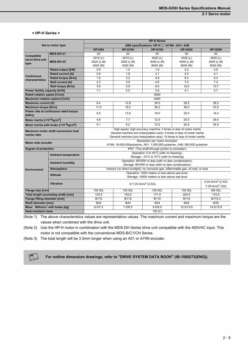
MDS-D/DH Series Specifications Manual
2-1 Servo motor
2 - 9
< HP-H Series >
(Note 1) The above characteristics values are representative values. The maximum current and maximum torque are the
values when combined with the drive unit.
(Note 2) Use the HP-H motor in combination with the MDS-DH Series drive unit compatible with the 400VAC input. This
motor is not compatible with the conventional MDS-B/C1/CH Series.
(Note 3) The total length will be 3.5mm longer when using an A51 or A74N encoder.
Servo motor type
HP-H Series
ABS specifications: HP-H -A74N/ -A51/ -A48
HP-H54 HP-H104 HP-H154 HP-H224 HP-H204
Compatible servo drive unit type
MDS-DH-V1 20 20 40 40 40
MDS-DH-V22010 (L)
2020 (L,M)4020 (M)
2010 (L)2020 (L,M)4020 (M)
4020 (L)4040 (L,M)8040 (M)
4020 (L)4040 (L,M)8040 (M)
4020 (L)4040 (L,M)8040 (M)
Continuous characteristics
Rated output [kW] 0.5 1.0 1.5 2.2 2.0
Rated current [A] 0.9 1.8 3.1 4.0 4.1
Rated torque [N•m] 1.6 3.2 4.8 6.4 6.4
Stall current [A] 2.2 3.9 4.8 7.0 7.3
Stall torque [N•m] 3.0 5.9 9.0 12.0 13.7
Power facility capacity [kVA] 1.1 2.0 2.8 4.1 3.7
Rated rotation speed [r/min] 3000
Maximum rotation speed [r/min] 4000
Maximum current [A] 8.4 12.8 26.0 28.5 28.5
Maximum torque [N•m] 11.0 19.2 36.5 46.0 43.0
Power rate at continuous rated torque [kW/s]
5.5 13.0 19.0 20.0 14.0
Motor inertia [×10-4kg•m2] 4.6 7.7 12.0 20.0 29.0
Motor inertia with brake [×10-4kg•m2] 5.1 8.2 12.5 20.5 34.5
Maximum motor shaft conversion load inertia ratio
High-speed, high-accuracy machine: 3 times or less of motor inertiaGeneral machine tool (interpolation axis): 5 times or less of motor inertia
General machine (non-interpolation axis): 10 times or less of motor inertia
Motor side encoderResolution per motor revolution
A74N: 16,000,000pulse/rev, A51: 1,000,000 pulse/rev, A48: 260,000 pulse/rev
Degree of protection IP67 (The shaft-through portion is excluded.)
Environment
Ambient temperatureOperation: 0 to 40°C (with no freezing),
Storage: -15°C to 70°C (with no freezing)
Ambient humidityOperation: 80%RH or less (with no dew condensation),
Storage: 90%RH or less (with no dew condensation)
Atmosphere Indoors (no direct sunlight); no corrosive gas, inflammable gas, oil mist, or dust
AltitudeOperation: 1000 meters or less above sea level,Storage: 10000 meters or less above sea level
Vibration X,Y:24.5m/s2 (2.5G)X:24.5m/s2 (2.5G)
Y:29.4m/s2 (3G)
Flange size [mm] 130 SQ. 130 SQ. 130 SQ. 130 SQ. 180 SQ.
Total length (excluding shaft) [mm] 133.5 152.5 171.5 204.5 172.5
Flange fitting diameter [mm] Φ110 Φ110 Φ110 Φ110 Φ114.3
Shaft diameter [mm] Φ24 Φ24 Φ24 Φ24 Φ35
Mass Without / with brake [kg] 6.0/7.3 7.0/8.5 8.0/9.5 12.0/13.9 14.0/15.9
Heat-resistant class 155 (F)
For outline dimension drawings, refer to "DRIVE SYSTEM DATA BOOK" (IB-1500273(ENG)).

2 Specifications
MITSUBISHI CNC
2 - 10
< HP-H Series >
(Note 1) The above characteristics values are representative values. The maximum current and maximum torque are the
values when combined with the drive unit.
(Note 2) Use the HP-H motor in combination with the MDS-DH Series drive unit compatible with the 400VAC input. This
motor is not compatible with the conventional MDS-B/C1/CH Series.
(Note 3) The total length will be 3.5mm longer when using an A51 or A74N encoder.
Servo motor type
HP-H Series
ABS specifications: HP-H -A74N/ -A51/ -A48
HP-H354 HP-H454 HP-H704 HP-H903 HP-H1103
Compatible servo drive unit type
MDS-DH-V1 80 80 80W 160 160W
MDS-DH-V28040 (L)
8080 (L,M)8080W (L,M)
8040 (L)8080 (L,M)
8080W (L,M)8080W (L,M) - -
Continuous characteristics
Rated output [kW] 3.5 4.5 7.0 9.0 11.0
Rated current [A] 7.4 7.6 10.6 12.9 15.0
Rated torque [N•m] 11.1 14.3 22.3 28.7 35.0
Stall current [A] 14.5 14.9 20.1 32.0 46.0
Stall torque [N•m] 22.5 31.9 49.0 70.0 110.0
Power facility capacity [kVA] 6.4 8.1 12.5 16.1 19.6
Rated rotation speed [r/min] 3000
Maximum rotation speed [r/min] 4000 3000
Maximum current [A] 58.0 58.0 58.0 86.0 106.0
Maximum torque [N•m] 66.0 95.0 120.0 170.0 260.0
Power rate at continuous rated torque [kW/s]
33.0 36.0 59.0 52.0 48.0
Motor inertia [×10-4kg•m2] 37.0 55.0 82.0 163.0 255.0
Motor inertia with brake [×10-4kg•m2] 42.5 60.5 87.5 187.0 2790
Maximum motor shaft conversion load inertia ratio
High-speed, high-accuracy machine: 3 times or less of motor inertiaGeneral machine tool (interpolation axis): 5 times or less of motor inertia
General machine (non-interpolation axis): 10 times or less of motor inertia
Motor side encoderResolution per motor revolution
A74N: 16,000,000pulse/rev, A51: 1,000,000 pulse/rev, A48: 260,000 pulse/rev
Degree of protection IP67 (The shaft-through portion is excluded.)
Environment
Ambient temperatureOperation: 0 to 40°C (with no freezing),
Storage: -15°C to 70°C (with no freezing)
Ambient humidityOperation: 80%RH or less (with no dew condensation),
Storage: 90%RH or less (with no dew condensation)
Atmosphere Indoors (no direct sunlight); no corrosive gas, inflammable gas, oil mist, or dust
AltitudeOperation: 1000 meters or less above sea level,Storage: 10000 meters or less above sea level
Vibration X:24.5m/s2 (2.5G) Y:29.4m/s2(3G) X,Y:9.8m/s2 (1G)
Flange size [mm] 180 SQ. 180 SQ. 180 SQ. 220 SQ. 220 SQ.
Total length (excluding shaft) [mm] 195.5 225.5 305.5 346.5 419.5
Flange fitting diameter [mm] Φ114.3 Φ114.3 Φ114.3 Φ200 Φ200
Shaft diameter [mm] Φ35 Φ35 Φ35 Φ55 Φ55
Mass Without / with brake [kg] 17.0/22.0 21.0/26.0 37.0/43.0 51.0/61.4 74.0/84.4
Heat-resistant class 155 (F)
For outline dimension drawings, refer to "DRIVE SYSTEM DATA BOOK" (IB-1500273(ENG)).
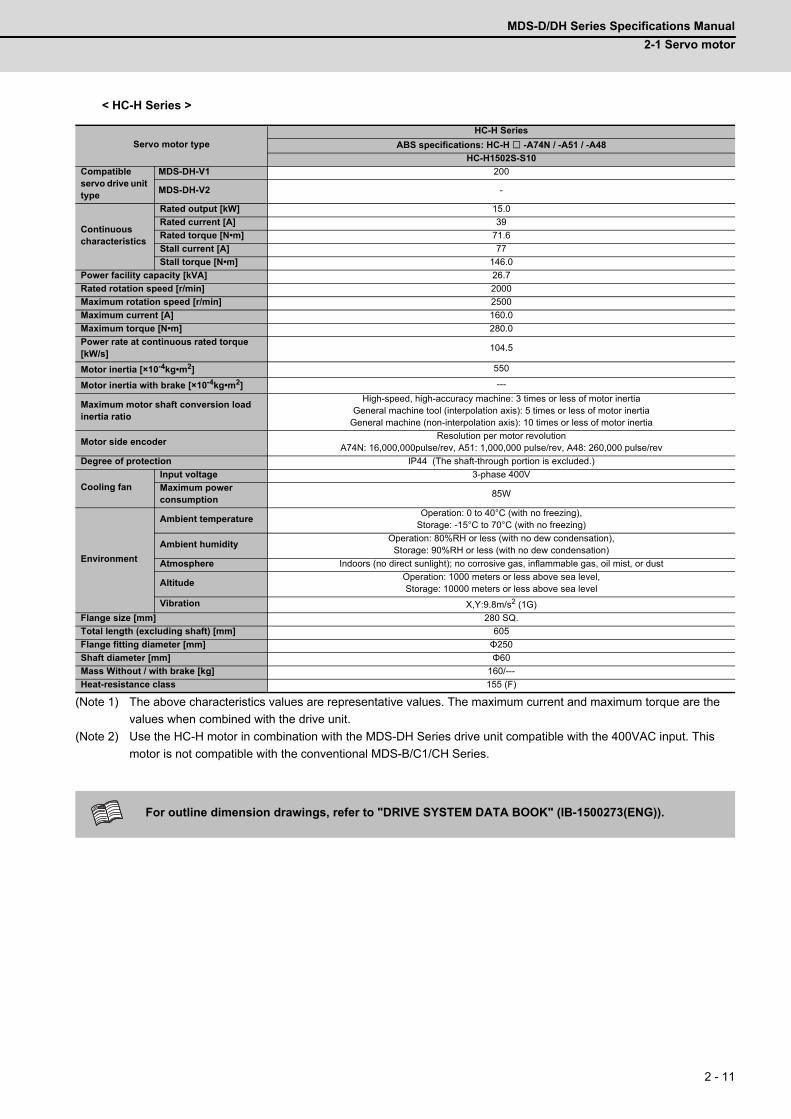
MDS-D/DH Series Specifications Manual
2-1 Servo motor
2 - 11
< HC-H Series >
(Note 1) The above characteristics values are representative values. The maximum current and maximum torque are the
values when combined with the drive unit.
(Note 2) Use the HC-H motor in combination with the MDS-DH Series drive unit compatible with the 400VAC input. This
motor is not compatible with the conventional MDS-B/C1/CH Series.
Servo motor type
HC-H Series
ABS specifications: HC-H -A74N / -A51 / -A48
HC-H1502S-S10
Compatible servo drive unit type
MDS-DH-V1 200
MDS-DH-V2 -
Continuous characteristics
Rated output [kW] 15.0
Rated current [A] 39
Rated torque [N•m] 71.6
Stall current [A] 77
Stall torque [N•m] 146.0
Power facility capacity [kVA] 26.7
Rated rotation speed [r/min] 2000
Maximum rotation speed [r/min] 2500
Maximum current [A] 160.0
Maximum torque [N•m] 280.0
Power rate at continuous rated torque [kW/s]
104.5
Motor inertia [×10-4kg•m2] 550
Motor inertia with brake [×10-4kg•m2] ---
Maximum motor shaft conversion load inertia ratio
High-speed, high-accuracy machine: 3 times or less of motor inertiaGeneral machine tool (interpolation axis): 5 times or less of motor inertia
General machine (non-interpolation axis): 10 times or less of motor inertia
Motor side encoderResolution per motor revolution
A74N: 16,000,000pulse/rev, A51: 1,000,000 pulse/rev, A48: 260,000 pulse/rev
Degree of protection IP44 (The shaft-through portion is excluded.)
Cooling fanInput voltage 3-phase 400V
Maximum power consumption
85W
Environment
Ambient temperatureOperation: 0 to 40°C (with no freezing),
Storage: -15°C to 70°C (with no freezing)
Ambient humidityOperation: 80%RH or less (with no dew condensation),
Storage: 90%RH or less (with no dew condensation)
Atmosphere Indoors (no direct sunlight); no corrosive gas, inflammable gas, oil mist, or dust
AltitudeOperation: 1000 meters or less above sea level,Storage: 10000 meters or less above sea level
Vibration X,Y:9.8m/s2 (1G)
Flange size [mm] 280 SQ.
Total length (excluding shaft) [mm] 605
Flange fitting diameter [mm] Φ250
Shaft diameter [mm] Φ60
Mass Without / with brake [kg] 160/---
Heat-resistance class 155 (F)
For outline dimension drawings, refer to "DRIVE SYSTEM DATA BOOK" (IB-1500273(ENG)).
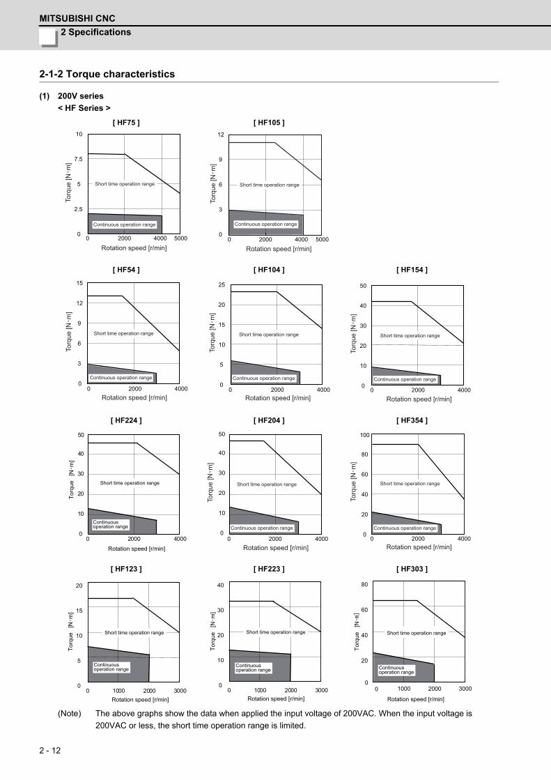
2 Specifications
MITSUBISHI CNC
2 - 12
2-1-2 Torque characteristics
(1) 200V series
< HF Series >
(Note) The above graphs show the data when applied the input voltage of 200VAC. When the input voltage is
200VAC or less, the short time operation range is limited.
[ HF75 ] [ HF105 ]
[ HF54 ] [ HF104 ] [ HF154 ]
[ HF224 ] [ HF204 ] [ HF354 ]
[ HF123 ] [ HF223 ] [ HF303 ]
0 2000 50000
2.5
5
7.5
10
4000
Rotation speed [r/min]
Torq
ue [N
m]
Short time operation range
Continuous operation range
0
3
6
9
12
0 2000 50004000 Rotation speed [r/min]
Torq
ue [N
m]
Short time operation range
Continuous operation range
0 2000 40000
3
9
12
15
6
Rotation speed [r/min]
Torq
ue [N
m]
Short time operation range
Continuous operation range
0 2000 40000
5
20
25
15
10
Rotation speed [r/min]
Torq
ue [N
m]
Short time operation range
Continuous operation range
0 2000 4000 0
10
40
50
30
20
Rotation speed [r/min]
Torq
ue [N
m]
Short time operation range
Continuous operation range
Torq
ue[N
m]
0 2000 40000
10
20
40
30
50
Rotation speed [r/min]
Short time operation range
Continuousoperation range
0 2000 4000 0
10
20
40
30
50
Rotation speed [r/min]
Torq
ue [N
m]
Short time operation range
Continuous operation range
0 2000 4000 0
20
40
100
80
60
Rotation speed [r/min]
Torq
ue [N
m]
Short time operation range
Continuous operation range
0 1000 30000
5
10
15
20
Torq
ue[N
m]
2000
Short time operation range
Rotation speed [r/min]
Continuousoperation range
Torq
ue [
Nm
]
0 1000 30000
10
20
30
40
2000
Short time operation range
Rotation speed [r/min]
Continuousoperation range
Torq
ue[N
Short time operation range
Rotation speed [r/min]
Continuousoperation range
20
40
60
80
1000 3000200000

MDS-D/DH Series Specifications Manual
2-1 Servo motor
2 - 13
< HF Series >
(Note) The above graphs show the data when applied the input voltage of 200VAC. When the input voltage is
200VAC or less, the short time operation range is limited.
[ HF453 ] [ HF703 ] [ HF903 ]
[ HF142 ] [ HF302 ]
0 1000 3500 0
25
100
125
75
50
2000 3000 Rotation speed [r/min]
Torq
ue [N
m]
Short time operation range
Continuous operation range
0 1000 3000 0
40
80
120
160
2000 Rotation speed [r/min]
Torq
ue [N
m]
Short time operation range
Continuous operation range0
60
120
180
240
0 1000 3000 2000 Rotation speed [r/min]
Torq
ue [N
m]
Short time operation range
Continuous operation range
Torq
ue
Short time operation range
Rotation speed [r/min]
Continuous operation range
0 1000 2000
6
12
24
18
30
0
0 1000 20000
40
20
60
Torq
ue[N
m]
Short time operation range
Rotation speed [r/min]
Continuous operation range
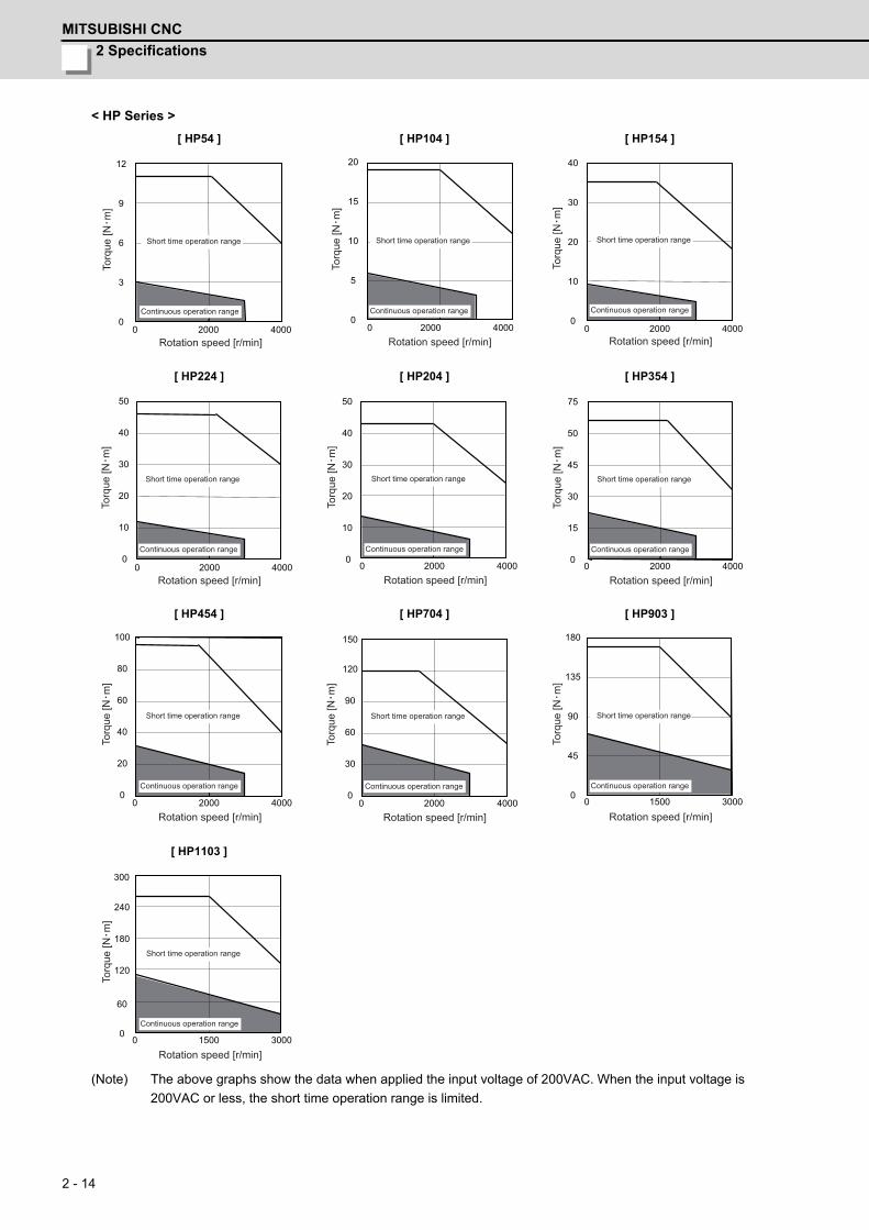
2 Specifications
MITSUBISHI CNC
2 - 14
< HP Series >
(Note) The above graphs show the data when applied the input voltage of 200VAC. When the input voltage is
200VAC or less, the short time operation range is limited.
[ HP54 ] [ HP104 ] [ HP154 ]
[ HP224 ] [ HP204 ] [ HP354 ]
[ HP454 ] [ HP704 ] [ HP903 ]
[ HP1103 ]
0 2000 4000 0
3
6
9
12
Rotation speed [r/min]
Torq
ue [N
m]
Short time operation range
Continuous operation range0
5
10
15
20
0 2000 4000 Rotation speed [r/min]
Torq
ue [N
m]
Short time operation range
Continuous operation range0
10
20
30
40
0 2000 4000 Rotation speed [r/min]
Torq
ue [N
m]
Short time operation range
Continuous operation range
0 2000 4000 0
10
30
40
50
20
Rotation speed [r/min]
Torq
ue [N
m]
Short time operation range
Continuous operation range
0 2000 4000 0
10
30
40
50
20
Rotation speed [r/min]
Torq
ue [N
m]
Short time operation range
Continuous operation range
0 2000 4000 0
15
50
75
45
30
Rotation speed [r/min]
Torq
ue [N
m]
Short time operation range
Continuous operation range
2000 4000 0
20
80
100
60
40
0Rotation speed [r/min]
Torq
ue [N
m]
Short time operation range
Continuous operation range
0 2000 4000 0
30
60
120
90
150
Rotation speed [r/min]
Torq
ue [N
m]
Short time operation range
Continuous operation range0
45
90
135
180
0 1500 3000
Rotation speed [r/min]
Torq
ue [N
m]
Short time operation range
Continuous operation range
0 1500 3000 0
60
240
300
180
120
Rotation speed [r/min]
Torq
ue [N
m]
Short time operation range
Continuous operation range
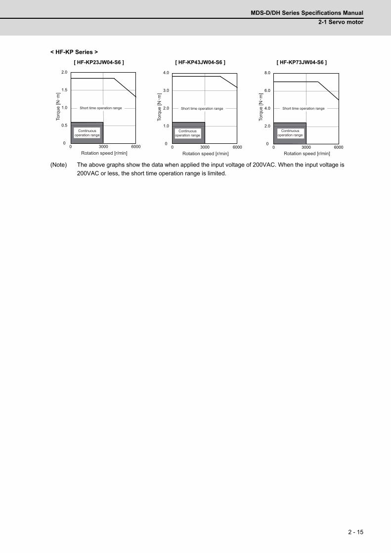
MDS-D/DH Series Specifications Manual
2-1 Servo motor
2 - 15
< HF-KP Series >
(Note) The above graphs show the data when applied the input voltage of 200VAC. When the input voltage is
200VAC or less, the short time operation range is limited.
[ HF-KP23JW04-S6 ] [ HF-KP43JW04-S6 ] [ HF-KP73JW04-S6 ]
0 3000 60000
0.5
1.0
1.5
2.0
Rotation speed [r/min]
Torq
ue [N
m]
Short time operation range
Continuous operation range
0
1.0
2.0
3.0
4.0
0 3000 6000Rotation speed [r/min]
Torq
ue [N
m]
Short time operation range
Continuous operation range
0
2.0
4.0
6.0
8.0
0 3000 6000Rotation speed [r/min]
Torq
ue [N
m]
Short time operation range
Continuous operation range
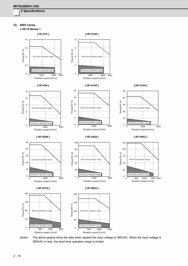
2 Specifications
MITSUBISHI CNC
2 - 16
(2) 400V series
< HF-H Series >
(Note) The above graphs show the data when applied the input voltage of 380VAC. When the input voltage is
380VAC or less, the short time operation range is limited.
[ HF-H75 ] [ HF-H105 ]
[ HF-H54 ] [ HF-H104 ] [ HF-H154 ]
[ HF-H204 ] [ HF-H354 ] [ HF-H453 ]
[ HF-H703 ] [ HF-H903 ]
0 2000 5000 0
2.5
5
7.5
10
4000 Rotation speed [r/min]
Torq
ue [N
m]
Short time operation range
Continuous operation range
0
3
6
9
12
0 2000 5000 4000 Rotation speed [r/min]
Torq
ue [N
m]
Short time operation range
Continuous operation range
0 2000 4000 0
3
9
12
15
6
Rotation speed [r/min]
Torq
ue [N
m]
Short time operation range
Continuous operation range
0 2000 4000 0
5
20
25
15
10
Rotation speed [r/min]
Torq
ue [N
m]
Short time operation range
Continuous operation range
0 2000 4000 0
10
40
50
30
20
Rotation speed [r/min]
Torq
ue [N
m]
Short time operation range
Continuous operation range
0 2000 4000 0
10
20
40
30
50
Rotation speed [r/min]
Torq
ue [N
m]
Short time operation range
Continuous operation range
0 2000 4000 0
20
40
100
80
60
Rotation speed [r/min]
Torq
ue [N
m]
Short time operation range
Continuous operation range
0 1000 3500 0
25
100
125
75
50
2000 3000 Rotation speed [r/min]
Torq
ue [N
m]
Short time operation range
Continuous operation range
0 1000 3000 0
40
80
120
160
2000
Rotation speed [r/min]
Torq
ue [N
m]
Short time operation range
Continuous operation range0
60
120
180
240
0 1000 3000 2000 Rotation speed [r/min]
Torq
ue [N
m]
Short time operation range
Continuous operation range
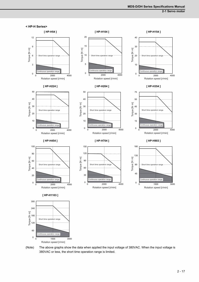
MDS-D/DH Series Specifications Manual
2-1 Servo motor
2 - 17
< HP-H Series>
(Note) The above graphs show the data when applied the input voltage of 380VAC. When the input voltage is
380VAC or less, the short time operation range is limited.
[ HP-H54 ] [ HP-H104 ] [ HP-H154 ]
[ HP-H224 ] [ HP-H204 ] [ HP-H354 ]
[ HP-H454 ] [ HP-H704 ] [ HP-H903 ]
[ HP-H1103 ]
0 2000 4000 0
3
6
9
12
Rotation speed [r/min]
Torq
ue [N
m]
Short time operation range
Continuous operation range0
5
10
15
20
0 2000 4000
Rotation speed [r/min]To
rque
[Nm
]
Short time operation range
Continuous operation range
0
10
20
30
40
0 2000 4000 Rotation speed [r/min]
Torq
ue [N
m]
Short time operation range
Continuous operation range
0 2000 4000 0
10
30
40
50
20
Rotation speed [r/min]
Torq
ue [N
m]
Short time operation range
Continuous operation range
0 2000 4000 0
10
30
40
50
20
Rotation speed [r/min]
Torq
ue [N
m]
Short time operation range
Continuous operation range
0 2000 4000 0
15
50
75
45
30
Rotation speed [r/min]To
rque
[Nm
]
Short time operation range
Continuous operation range
2000 4000 0
20
80
100
60
40
0Rotation speed [r/min]
Torq
ue [N
m]
Short time operation range
Continuous operation range
0 2000 4000 0
30
60
120
90
150
Rotation speed [r/min]
Torq
ue [N
m]
Short time operation range
Continuous operation range
0
45
90
135
180
0 1500 3000 Rotation speed [r/min]
Torq
ue [N
m]
Short time operation range
Continuous operation range
0 1500 3000 0
60
240
300
180
120
Rotation speed [r/min]
Torq
ue [N
m]
Short time operation range
Continuous operation range
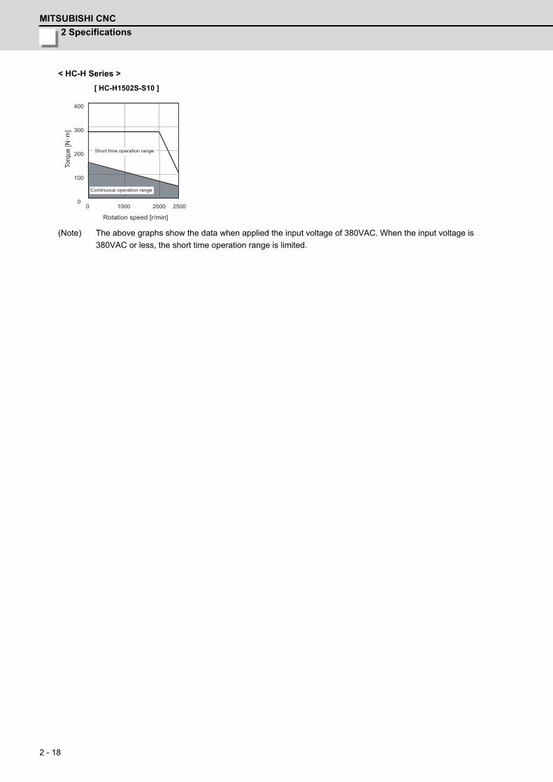
2 Specifications
MITSUBISHI CNC
2 - 18
< HC-H Series >
(Note) The above graphs show the data when applied the input voltage of 380VAC. When the input voltage is
380VAC or less, the short time operation range is limited.
[ HC-H1502S-S10 ]
0 1000 2500 0
100
200
300
400
2000
Rotation speed [r/min]
Torq
ue [N
m]
Short time operation range
Continuous operation range
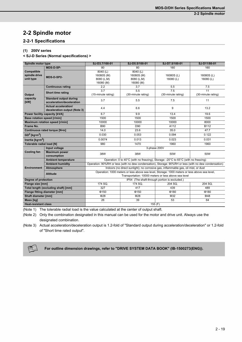
MDS-D/DH Series Specifications Manual
2-2 Spindle motor
2 - 19
2-2 Spindle motor2-2-1 Specifications
(1) 200V series
< SJ-D Series (Normal specifications) >
(Note 1) The tolerable radial load is the value calculated at the center of output shaft.
(Note 2) Only the combination designated in this manual can be used for the motor and drive unit. Always use the
designated combination.
(Note 3) Actual acceleration/deceleration output is 1.2-fold of "Standard output during acceleration/deceleration" or 1.2-fold
of "Short time rated output".
Spindle motor type SJ-D3.7/100-01 SJ-D5.5/100-01 SJ-D7.5/100-01 SJ-D11/80-01
Compatible spindle drive unit type
MDS-D-SP- 80 80 160 160
MDS-D-SP2-
8040 (L)16080S (M)8080 (L,M)16080 (M)
8040 (L)16080S (M)8080 (L,M)16080 (M)
16080S (L)16080 (L)
16080S (L)16080 (L)
Output capacity [kW]
Continuous rating 2.2 3.7 5.5 7.5
Short time rating3.7
(15-minute rating)5.5
(30-minute rating)7.5
(30-minute rating)11
(30-minute rating)
Standard output during acceleration/deceleration
3.7 5.5 7.5 11
Actual acceleration/deceleration output (Note 3)
4.4 6.6 9 13.2
Power facility capacity [kVA] 6.7 9.9 13.4 19.6
Base rotation speed [r/min] 1500 1500 1500 1500
Maximum rotation speed [r/min] 10000 10000 10000 8000
Frame No. B90 D90 A112 B112
Continuous rated torque [N•m] 14.0 23.6 35.0 47.7
GD2 [kg•m2] 0.030 0.053 0.094 0.122
Inertia [kg•m2] 0.0074 0.013 0.023 0.031
Tolerable radial load [N] 980 1470 1960 1960
Cooling fanInput voltage 3-phase 200V
Maximum power consumption
38W 38W 50W 50W
Environment
Ambient temperature Operation: 0 to 40°C (with no freezing), Storage: -20°C to 65°C (with no freezing)
Ambient humidity Operation: 90%RH or less (with no dew condensation), Storage: 90%RH or less (with no dew condensation)
Atmosphere Indoors (no direct sunlight); no corrosive gas, inflammable gas, oil mist, or dust
AltitudeOperation: 1000 meters or less above sea level, Storage: 1000 meters or less above sea level,
Transportation: 10000 meters or less above sea level
Degree of protection IP54 (The shaft-through portion is excluded.)
Flange size [mm] 174 SQ. 174 SQ. 204 SQ. 204 SQ.
Total length (excluding shaft) [mm] 327 417 439 489
Flange fitting diameter [mm] Φ150 Φ150 Φ180 Φ180
Shaft diameter [mm] Φ28 Φ28 Φ32 Φ48
Mass [kg] 26 39 53 64
Heat-resistant class 155 (F)
For outline dimension drawings, refer to "DRIVE SYSTEM DATA BOOK" (IB-1500273(ENG)).
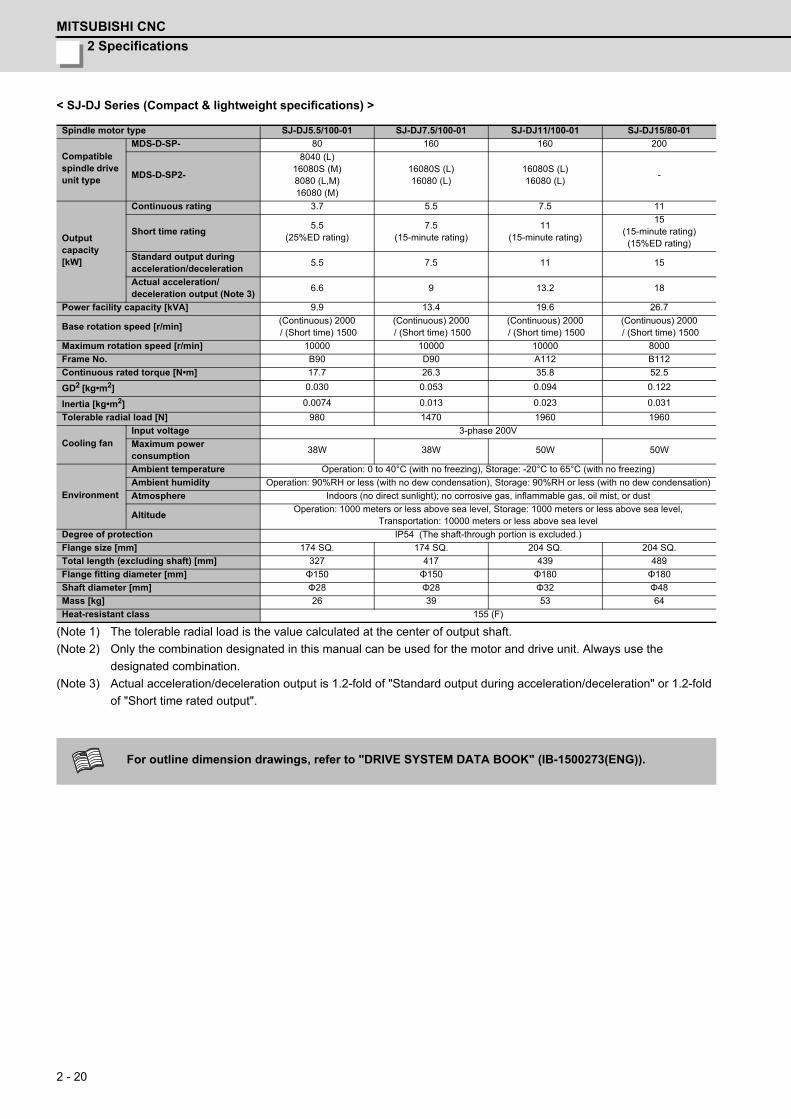
2 Specifications
MITSUBISHI CNC
2 - 20
< SJ-DJ Series (Compact & lightweight specifications) >
(Note 1) The tolerable radial load is the value calculated at the center of output shaft.
(Note 2) Only the combination designated in this manual can be used for the motor and drive unit. Always use the
designated combination.
(Note 3) Actual acceleration/deceleration output is 1.2-fold of "Standard output during acceleration/deceleration" or 1.2-fold
of "Short time rated output".
Spindle motor type SJ-DJ5.5/100-01 SJ-DJ7.5/100-01 SJ-DJ11/100-01 SJ-DJ15/80-01
Compatible spindle drive unit type
MDS-D-SP- 80 160 160 200
MDS-D-SP2-
8040 (L)16080S (M)8080 (L,M)16080 (M)
16080S (L)16080 (L)
16080S (L)16080 (L)
-
Output capacity [kW]
Continuous rating 3.7 5.5 7.5 11
Short time rating5.5
(25%ED rating)7.5
(15-minute rating)11
(15-minute rating)
15(15-minute rating)(15%ED rating)
Standard output during acceleration/deceleration
5.5 7.5 11 15
Actual acceleration/deceleration output (Note 3)
6.6 9 13.2 18
Power facility capacity [kVA] 9.9 13.4 19.6 26.7
Base rotation speed [r/min](Continuous) 2000 / (Short time) 1500
(Continuous) 2000 / (Short time) 1500
(Continuous) 2000 / (Short time) 1500
(Continuous) 2000 / (Short time) 1500
Maximum rotation speed [r/min] 10000 10000 10000 8000
Frame No. B90 D90 A112 B112
Continuous rated torque [N•m] 17.7 26.3 35.8 52.5
GD2 [kg•m2] 0.030 0.053 0.094 0.122
Inertia [kg•m2] 0.0074 0.013 0.023 0.031
Tolerable radial load [N] 980 1470 1960 1960
Cooling fanInput voltage 3-phase 200V
Maximum power consumption
38W 38W 50W 50W
Environment
Ambient temperature Operation: 0 to 40°C (with no freezing), Storage: -20°C to 65°C (with no freezing)
Ambient humidity Operation: 90%RH or less (with no dew condensation), Storage: 90%RH or less (with no dew condensation)
Atmosphere Indoors (no direct sunlight); no corrosive gas, inflammable gas, oil mist, or dust
AltitudeOperation: 1000 meters or less above sea level, Storage: 1000 meters or less above sea level,
Transportation: 10000 meters or less above sea level
Degree of protection IP54 (The shaft-through portion is excluded.)
Flange size [mm] 174 SQ. 174 SQ. 204 SQ. 204 SQ.
Total length (excluding shaft) [mm] 327 417 439 489
Flange fitting diameter [mm] Φ150 Φ150 Φ180 Φ180
Shaft diameter [mm] Φ28 Φ28 Φ32 Φ48
Mass [kg] 26 39 53 64
Heat-resistant class 155 (F)
For outline dimension drawings, refer to "DRIVE SYSTEM DATA BOOK" (IB-1500273(ENG)).

MDS-D/DH Series Specifications Manual
2-2 Spindle motor
2 - 21
< SJ-V Series (Normal specifications) >
(Note 1) The tolerable radial load is the value calculated at the center of output shaft.
(Note 2) Only the combination designated in this manual can be used for the motor and drive unit. Always use the
designated combination.
(Note 3) Actual acceleration/deceleration output is 1.2-fold of "Standard output during acceleration/deceleration" or 1.2-fold
of "Short time rated output".
Spindle motor type SJ-VL0.75-01T SJ-VL1.5-01T SJ-V2.2-01T SJ-V3.7-01T SJ-V3.7-02ZT SJ-V5.5-01ZT
Compatible spindle drive unit type
MDS-D-SP- 20 20 40 80 80 80
MDS-D-SP2-2020 (L,M)4020 (M)
2020 (L,M)4020 (M)
4020 (L)4040S (L,M)4040 (L,M)8040 (M)
8040 (L)16080S (M)8080 (L,M)16080 (M)
8040 (L)16080S (M)8080 (L,M)16080 (M)
8040 (L)16080S (M)8080 (L,M)16080 (M)
Output capacity [kW]
Continuous rating 0.4 0.75 1.5 2.2 2.2 3.7
Short time rating0.75
(10-minute rating)
1.5(10-minute
rating)
2.2(15-minute
rating)
3.7(15-minute
rating)
3.7 (15-minute
rating)
5.5(30-minute
rating)
Standard output during acceleration/deceleration
0.75 1.5 2.2 3.7 3.7 5.5
Actual acceleration/deceleration output (Note 3)
0.9 1.8 2.6 4.4 4.4 6.6
Power facility capacity [kVA] 1.5 2.8 4.1 6.7 6.7 9.9
Base rotation speed [r/min] 1500 1500 1500 1500 3000 1500
Maximum rotation speed [r/min] 10000 10000 10000 10000 15000 12000
Frame No. A71 B71 A90 B90 A90 D90
Continuous rated torque [N•m] 2.55 4.77 9.5 14.0 7.0 23.6
GD2 [kg•m2] 0.0053 0.0096 0.027 0.035 0.027 0.059
Inertia [kg•m2] 0.0013 0.0024 0.00675 0.009 0.00675 0.0148
Tolerable radial load [N] 490 490 980 980 245 980
Cooling fanInput voltage
Single-phase 200V
Single-phase 200V
Single-phase 200V
Single-phase 200V
Single-phase 200V
Single-phase 200V
Maximum power consumption
14W 14W 36W 36W 36W 36W
Environment
Ambient temperature Operation: 0 to 40°C (with no freezing), Storage: -20°C to 65°C (with no freezing)
Ambient humidity Operation: 90%RH or less (with no dew condensation), Storage: 90%RH or less (with no dew condensation)
Atmosphere Indoors (no direct sunlight); no corrosive gas, inflammable gas, oil mist, or dust
AltitudeOperation: 1000 meters or less above sea level, Storage: 1000 meters or less above sea level,
Transportation: 10000 meters or less above sea level
Degree of protection IP44
Flange size [mm] 130 SQ. 130 SQ. 174 SQ. 174 SQ. 174 SQ. 174 SQ.
Total length (excluding shaft) [mm] 265 325 300 330 300 425
Flange fitting diameter [mm] Φ110 Φ110 Φ150 Φ150 Φ150 Φ150
Shaft diameter [mm] Φ22 Φ22 Φ28 Φ28 Φ28 Φ28
Mass [kg] 15 20 25 30 25 49
Heat-resistant class 155 (F)
For outline dimension drawings, refer to "DRIVE SYSTEM DATA BOOK" (IB-1500273(ENG)).

2 Specifications
MITSUBISHI CNC
2 - 22
< SJ-V Series (Normal specifications) >
(Note 1) The tolerable radial load is the value calculated at the center of output shaft.
(Note 2) Only the combination designated in this manual can be used for the motor and drive unit. Always use the
designated combination.
(Note 3) Actual acceleration/deceleration output is 1.2-fold of "Standard output during acceleration/deceleration" or 1.2-fold
of "Short time rated output".
Spindle motor type SJ-V7.5-01ZT SJ-V7.5-03ZT SJ-V11-01ZT SJ-V11-06ZT SJ-V11-08ZT SJ-V11-13ZT
Compatible spindle drive unit type
MDS-D-SP- 160 160 160 200 200 200
MDS-D-SP2-16080S (L)16080 (L)
16080S (L)16080 (L)
16080S (L)16080 (L)
- - -
Output capacity [kW]
Continuous rating 5.5 5.5 7.5 5.5 7.5 7.5
Short time rating7.5
(30-minute rating)
7.5(30-minute
rating)
11(30-minute
rating)
7.5(30-minute
rating)
11(30-minute
rating)
11(30-minute
rating)
Standard output during acceleration/deceleration
7.5 7.5 11 7.5 11 11
Actual acceleration/deceleration output (Note 3)
9 9 13.2 9 13.2 13.2
Power facility capacity [kVA] 13.4 13.4 19.6 13.4 19.6 19.6
Base rotation speed [r/min] 1500 1500 1500 1500 1500 1500
Maximum rotation speed [r/min] 12000 12000 8000 12000 8000 8000
Frame No. A112 A112 B112 A112 B112 B112
Continuous rated torque [N•m] 35 35 47.7 35.0 47.7 47.7
GD2 [kg•m2] 0.098 0.098 0.12 0.098 0.12 0.12
Inertia [kg•m2] 0.0245 0.0245 0.03 0.025 0.03 0.03
Tolerable radial load [N] 980 980 1960 980 1470 1960
Cooling fanInput voltage 3-phase 200V 3-phase 200V 3-phase 200V 3-phase 200V 3-phase 200V 3-phase 200V
Maximum power consumption
70W 70W 40W 40W 40W 70W
Environment
Ambient temperature Operation: 0 to 40°C (with no freezing), Storage: -20°C to 65°C (with no freezing)
Ambient humidity Operation: 90%RH or less (with no dew condensation), Storage: 90%RH or less (with no dew condensation)
Atmosphere Indoors (no direct sunlight); no corrosive gas, inflammable gas, oil mist, or dust
AltitudeOperation: 1000 meters or less above sea level, Storage: 1000 meters or less above sea level,
Transportation: 10000 meters or less above sea level
Degree of protection IP44
Flange size [mm] 204 SQ. 204 SQ. 204 SQ. 204 SQ. 204 SQ. 204 SQ.
Total length (excluding shaft) [mm] 440 440 490 440 490 490
Flange fitting diameter [mm] Φ180 Φ180 Φ180 Φ180 Φ180 Φ180
Shaft diameter [mm] Φ32 Φ32 Φ48 Φ32 Φ48 Φ48
Mass [kg] 60 60 70 60 70 70
Heat-resistant class 155 (F)
For outline dimension drawings, refer to "DRIVE SYSTEM DATA BOOK" (IB-1500273(ENG)).
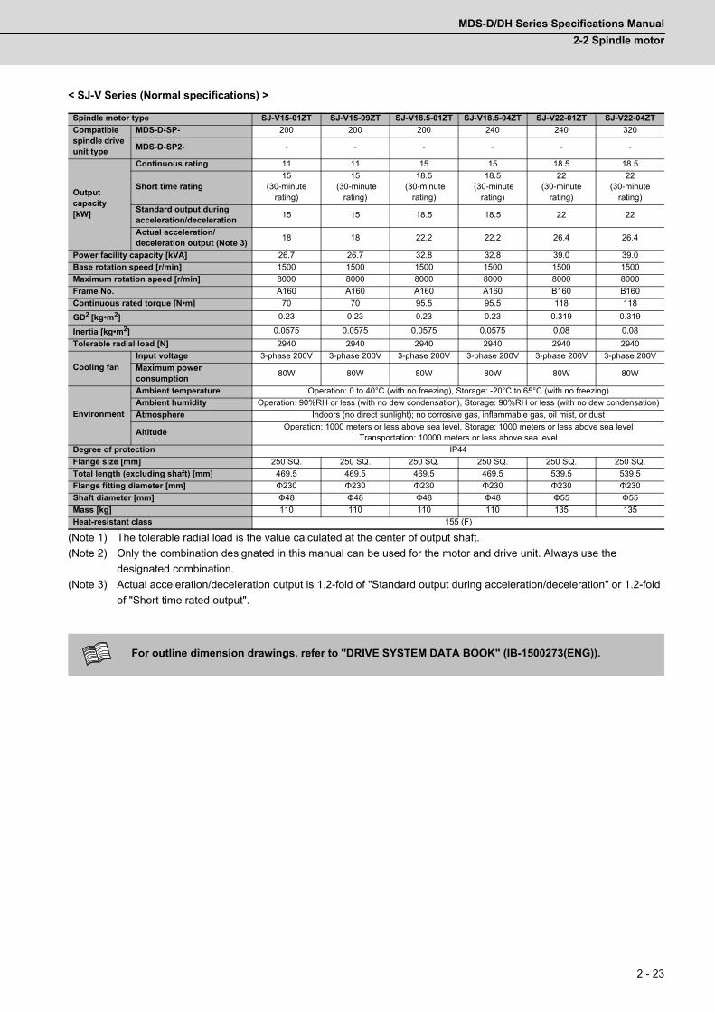
MDS-D/DH Series Specifications Manual
2-2 Spindle motor
2 - 23
< SJ-V Series (Normal specifications) >
(Note 1) The tolerable radial load is the value calculated at the center of output shaft.
(Note 2) Only the combination designated in this manual can be used for the motor and drive unit. Always use the
designated combination.
(Note 3) Actual acceleration/deceleration output is 1.2-fold of "Standard output during acceleration/deceleration" or 1.2-fold
of "Short time rated output".
Spindle motor type SJ-V15-01ZT SJ-V15-09ZT SJ-V18.5-01ZT SJ-V18.5-04ZT SJ-V22-01ZT SJ-V22-04ZT
Compatible spindle drive unit type
MDS-D-SP- 200 200 200 240 240 320
MDS-D-SP2- - - - - - -
Output capacity [kW]
Continuous rating 11 11 15 15 18.5 18.5
Short time rating15
(30-minute rating)
15 (30-minute
rating)
18.5 (30-minute
rating)
18.5 (30-minute
rating)
22 (30-minute
rating)
22 (30-minute
rating)
Standard output during acceleration/deceleration
15 15 18.5 18.5 22 22
Actual acceleration/deceleration output (Note 3)
18 18 22.2 22.2 26.4 26.4
Power facility capacity [kVA] 26.7 26.7 32.8 32.8 39.0 39.0
Base rotation speed [r/min] 1500 1500 1500 1500 1500 1500
Maximum rotation speed [r/min] 8000 8000 8000 8000 8000 8000
Frame No. A160 A160 A160 A160 B160 B160
Continuous rated torque [N•m] 70 70 95.5 95.5 118 118
GD2 [kg•m2] 0.23 0.23 0.23 0.23 0.319 0.319
Inertia [kg•m2] 0.0575 0.0575 0.0575 0.0575 0.08 0.08
Tolerable radial load [N] 2940 2940 2940 2940 2940 2940
Cooling fanInput voltage 3-phase 200V 3-phase 200V 3-phase 200V 3-phase 200V 3-phase 200V 3-phase 200V
Maximum power consumption
80W 80W 80W 80W 80W 80W
Environment
Ambient temperature Operation: 0 to 40°C (with no freezing), Storage: -20°C to 65°C (with no freezing)
Ambient humidity Operation: 90%RH or less (with no dew condensation), Storage: 90%RH or less (with no dew condensation)
Atmosphere Indoors (no direct sunlight); no corrosive gas, inflammable gas, oil mist, or dust
AltitudeOperation: 1000 meters or less above sea level, Storage: 1000 meters or less above sea level
Transportation: 10000 meters or less above sea level
Degree of protection IP44
Flange size [mm] 250 SQ. 250 SQ. 250 SQ. 250 SQ. 250 SQ. 250 SQ.
Total length (excluding shaft) [mm] 469.5 469.5 469.5 469.5 539.5 539.5
Flange fitting diameter [mm] Φ230 Φ230 Φ230 Φ230 Φ230 Φ230
Shaft diameter [mm] Φ48 Φ48 Φ48 Φ48 Φ55 Φ55
Mass [kg] 110 110 110 110 135 135
Heat-resistant class 155 (F)
For outline dimension drawings, refer to "DRIVE SYSTEM DATA BOOK" (IB-1500273(ENG)).
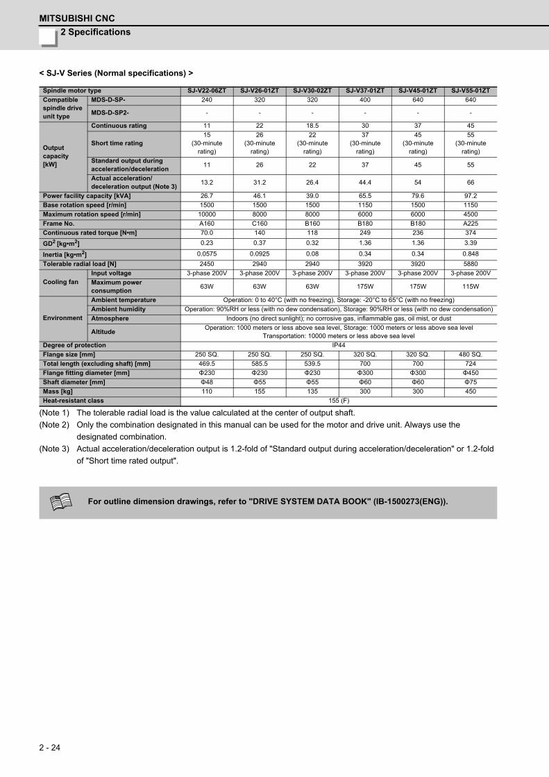
2 Specifications
MITSUBISHI CNC
2 - 24
< SJ-V Series (Normal specifications) >
(Note 1) The tolerable radial load is the value calculated at the center of output shaft.
(Note 2) Only the combination designated in this manual can be used for the motor and drive unit. Always use the
designated combination.
(Note 3) Actual acceleration/deceleration output is 1.2-fold of "Standard output during acceleration/deceleration" or 1.2-fold
of "Short time rated output".
Spindle motor type SJ-V22-06ZT SJ-V26-01ZT SJ-V30-02ZT SJ-V37-01ZT SJ-V45-01ZT SJ-V55-01ZT
Compatible spindle drive unit type
MDS-D-SP- 240 320 320 400 640 640
MDS-D-SP2- - - - - - -
Output capacity [kW]
Continuous rating 11 22 18.5 30 37 45
Short time rating15
(30-minute rating)
26(30-minute
rating)
22(30-minute
rating)
37(30-minute
rating)
45(30-minute
rating)
55(30-minute
rating)
Standard output during acceleration/deceleration
11 26 22 37 45 55
Actual acceleration/deceleration output (Note 3)
13.2 31.2 26.4 44.4 54 66
Power facility capacity [kVA] 26.7 46.1 39.0 65.5 79.6 97.2
Base rotation speed [r/min] 1500 1500 1500 1150 1500 1150
Maximum rotation speed [r/min] 10000 8000 8000 6000 6000 4500
Frame No. A160 C160 B160 B180 B180 A225
Continuous rated torque [N•m] 70.0 140 118 249 236 374
GD2 [kg•m2] 0.23 0.37 0.32 1.36 1.36 3.39
Inertia [kg•m2] 0.0575 0.0925 0.08 0.34 0.34 0.848
Tolerable radial load [N] 2450 2940 2940 3920 3920 5880
Cooling fanInput voltage 3-phase 200V 3-phase 200V 3-phase 200V 3-phase 200V 3-phase 200V 3-phase 200V
Maximum power consumption
63W 63W 63W 175W 175W 115W
Environment
Ambient temperature Operation: 0 to 40°C (with no freezing), Storage: -20°C to 65°C (with no freezing)
Ambient humidity Operation: 90%RH or less (with no dew condensation), Storage: 90%RH or less (with no dew condensation)
Atmosphere Indoors (no direct sunlight); no corrosive gas, inflammable gas, oil mist, or dust
AltitudeOperation: 1000 meters or less above sea level, Storage: 1000 meters or less above sea level
Transportation: 10000 meters or less above sea level
Degree of protection IP44
Flange size [mm] 250 SQ. 250 SQ. 250 SQ. 320 SQ. 320 SQ. 480 SQ.
Total length (excluding shaft) [mm] 469.5 585.5 539.5 700 700 724
Flange fitting diameter [mm] Φ230 Φ230 Φ230 Φ300 Φ300 Φ450
Shaft diameter [mm] Φ48 Φ55 Φ55 Φ60 Φ60 Φ75
Mass [kg] 110 155 135 300 300 450
Heat-resistant class 155 (F)
For outline dimension drawings, refer to "DRIVE SYSTEM DATA BOOK" (IB-1500273(ENG)).
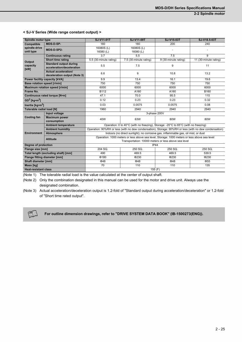
MDS-D/DH Series Specifications Manual
2-2 Spindle motor
2 - 25
< SJ-V Series (Wide range constant output) >
(Note 1) The tolerable radial load is the value calculated at the center of output shaft.
(Note 2) Only the combination designated in this manual can be used for the motor and drive unit. Always use the
designated combination.
(Note 3) Actual acceleration/deceleration output is 1.2-fold of "Standard output during acceleration/deceleration" or 1.2-fold
of "Short time rated output".
Spindle motor type SJ-V11-01T SJ-V11-09T SJ-V15-03T SJ-V18.5-03T
Compatible spindle drive unit type
MDS-D-SP- 160 160 200 240
MDS-D-SP2-16080S (L)16080 (L)
16080S (L)16080 (L)
- -
Output capacity [kW]
Continuous rating 3.7 5.5 7.5 9
Short time rating 5.5 (30-minute rating) 7.5 (30-minute rating) 9 (30-minute rating) 11 (30-minute rating)
Standard output during acceleration/deceleration
5.5 7.5 9 11
Actual acceleration/deceleration output (Note 3)
6.6 9 10.8 13.2
Power facility capacity [kVA] 9.9 13.4 16.1 19.6
Base rotation speed [r/min] 750 750 750 750
Maximum rotation speed [r/min] 6000 6000 6000 6000
Frame No. B112 A160 A160 B160
Continuous rated torque [N•m] 47.1 70.0 95.5 115
GD2 [kg•m2] 0.12 0.23 0.23 0.32
Inertia [kg•m2] 0.03 0.0575 0.0575 0.08
Tolerable radial load [N] 1960 2940 2940 2940
Cooling fanInput voltage 3-phase 200V
Maximum power consumption
40W 63W 80W 80W
Environment
Ambient temperature Operation: 0 to 40°C (with no freezing), Storage: -20°C to 65°C (with no freezing)
Ambient humidity Operation: 90%RH or less (with no dew condensation), Storage: 90%RH or less (with no dew condensation)
Atmosphere Indoors (no direct sunlight); no corrosive gas, inflammable gas, oil mist, or dust
AltitudeOperation: 1000 meters or less above sea level, Storage: 1000 meters or less above sea level
Transportation: 10000 meters or less above sea level
Degree of protection IP44
Flange size [mm] 204 SQ. 250 SQ. 250 SQ. 250 SQ.
Total length (excluding shaft) [mm] 490 469.5 469.5 539.5
Flange fitting diameter [mm] Φ180 Φ230 Φ230 Φ230
Shaft diameter [mm] Φ48 Φ48 Φ48 Φ55
Mass [kg] 70 110 110 135
Heat-resistant class 155 (F)
For outline dimension drawings, refer to "DRIVE SYSTEM DATA BOOK" (IB-1500273(ENG)).
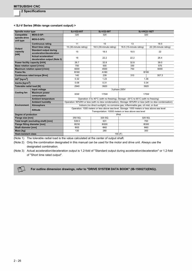
2 Specifications
MITSUBISHI CNC
2 - 26
< SJ-V Series (Wide range constant output) >
(Note 1) The tolerable radial load is the value calculated at the center of output shaft.
(Note 2) Only the combination designated in this manual can be used for the motor and drive unit. Always use the
designated combination.
(Note 3) Actual acceleration/deceleration output is 1.2-fold of "Standard output during acceleration/deceleration" or 1.2-fold
of "Short time rated output".
Spindle motor type SJ-V22-05T SJ-V22-09T SJ-VK22-19ZT
Compatible spindle drive unit type
MDS-D-SP- 320 320 320
MDS-D-SP2- - - -
Output capacity [kW]
Continuous rating 11 15 13 18.5
Short time rating 15 (30-minute rating) 18.5 (30-minute rating) 18.5 (15-minute rating) 22 (30-minute rating)
Standard output duringacceleration/deceleration
15 18.5 18.5 22
Actual acceleration/deceleration output (Note 3)
18 22.2 22.2 26.4
Power facility capacity [kVA] 26.7 32.8 32.8 39.0
Base rotation speed [r/min] 750 500 330 575
Maximum rotation speed [r/min] 6000 4500 750 6000
Frame No. B160 A180 B180
Continuous rated torque [N•m] 140 239 310 307.3
GD2 [kg•m2] 0.32 1.23 1.36
Inertia [kg•m2] 0.08 0.31 0.34
Tolerable radial load [N] 2940 3920 3920
Cooling fanInput voltage 3-phase 200V
Maximum power consumption
63W 175W 175W
Environment
Ambient temperature Operation: 0 to 40°C (with no freezing), Storage: -20°C to 65°C (with no freezing)
Ambient humidity Operation: 90%RH or less (with no dew condensation), Storage: 90%RH or less (with no dew condensation)
Atmosphere Indoors (no direct sunlight); no corrosive gas, inflammable gas, oil mist, or dust
AltitudeOperation: 1000 meters or less above sea level, Storage: 1000 meters or less above sea level
Transportation: 10000 meters or less above sea level
Degree of protection IP44
Flange size [mm] 250 SQ. 320 SQ. 320 SQ.
Total length (excluding shaft) [mm] 539.5 631 700
Flange fitting diameter [mm] Φ230 Φ300 Φ300
Shaft diameter [mm] Φ55 Φ60 Φ60
Mass [kg] 135 280 300
Heat-resistant class 155 (F)
For outline dimension drawings, refer to "DRIVE SYSTEM DATA BOOK" (IB-1500273(ENG)).

MDS-D/DH Series Specifications Manual
2-2 Spindle motor
2 - 27
< SJ-VL Series (Low-inertia) >
(Note 1) The tolerable radial load is the value calculated at the center of output shaft.
(Note 2) Only the combination designated in this manual can be used for the motor and drive unit. Always use the
designated combination.
(Note 3) Actual acceleration/deceleration output is 1.2-fold of "Standard output during acceleration/deceleration" or 1.2-fold
of "Short time rated output".
Spindle motor type SJ-VL2.2-02ZTSJ-VL11-
05FZT-S01SJ-VL11-10FZT SJ-VL11-10FZT SJ-VL11-07ZT SJ-VL11-07ZT
Compatible spindle drive unit type
MDS-D-SP- 40 160 160 160 160 160
MDS-D-SP2-
4020 (L)4040S (L,M)4040 (L,M)8040 (M)
16080S (L)16080 (L)
16080S (L)16080 (L)
-16080S (L)16080 (L)
16080S (L)16080 (L)
Output capacity [kW]
Continuous rating 1.5 1.5 2.2 3.7 5.5 7.5
Short time rating2.2
(15-minute rating)
3 (10-minute
rating)
3.7 (15-minute
rating)
5.5 (15-minute
rating)
7.5 (30-minute
rating)
11 (15-minute
rating)
Standard output duringacceleration/deceleration
2.2 11 11 11 11 11
Actual acceleration/deceleration output (Note 3)
2.6 13.2 13.2 13.2 13.2 13.2
Power facility capacity [kVA] 4.1 5.5 6.7 9.9 13.4 19.6
Base rotation speed [r/min] 3000 5000 17003000
(10-minute rating: 2500)
1500 2200
Maximum rotation speed [r/min] 15000 20000 15000 15000 12000 12000
Frame No. B71 B71 D90 D90 B112 B112
Continuous rated torque [N•m] 4.77 2.8 12.4 11.8 35 32.6
GD2 [kg•m2] 0.0096 0.0096 0.021 0.021 0.072 0.072
Inertia [kg•m2] 0.0024 0.0024 0.00525 0.00525 0.018 0.018
Tolerable radial load [N] 196 98 245 245 980 980
Cooling fanInput voltage
Single-phase 200V
Single-phase 200V
Single-phase 200V
Single-phase 200V
3-phase 200V 3-phase 200V
Maximum power consumption
14W 14W 41W 41W 70W 70W
Environment
Ambient temperature Operation: 0 to 40°C (with no freezing), Storage: -20°C to 65°C (with no freezing)
Ambient humidity Operation: 90%RH or less (with no dew condensation), Storage: 90%RH or less (with no dew condensation)
Atmosphere Indoors (no direct sunlight); no corrosive gas, inflammable gas, oil mist, or dust
AltitudeOperation: 1000 meters or less above sea level, Storage: 1000 meters or less above sea level
Transportation: 10000 meters or less above sea level
Degree of protection IP44
Flange size [mm] 130 SQ. 130 SQ. 174 SQ. 174 SQ. 204 SQ. 204 SQ.
Total length (excluding shaft) [mm] 325 335 441 441 490 490
Flange fitting diameter [mm] Φ110 Φ110 Φ150 Φ150 Φ180 Φ180
Shaft diameter [mm] Φ22 Φ22 Φ28 Φ28 Φ32 Φ32
Mass [kg] 20 20 40 40 70 70
Heat-resistant class 155 (F)
For outline dimension drawings, refer to "DRIVE SYSTEM DATA BOOK" (IB-1500273(ENG)).

2 Specifications
MITSUBISHI CNC
2 - 28
(2) 400V series
< SJ-4-V Series (Normal specifications) >
(Note 1) The tolerable radial load is the value calculated at the center of output shaft.
(Note 2) Only the combination designated in this manual can be used for the motor and drive unit. Always use the
designated combination.
(Note 3) Actual acceleration/deceleration output is 1.2-fold of "Standard output during acceleration/deceleration" or 1.2-fold
of "Short time rated output".
(Note 4) The rated output is guaranteed at the rated input voltage (380 to 440VAC 50Hz / 380 to 480VAC 60Hz) to the
power supply unit. If the input voltage fluctuates and drops below 380VAC, the rated output may not be attained.
Spindle motor type SJ-4-V2.2-03T SJ-4-V3.7-03T SJ-4-V3.7-05ZT SJ-4-V5.5-07T SJ-4-V7.5-12T SJ-4-V7.5-13ZT
Compatible spindle drive unit type
MDS-DH-SP- 20 20 20 40 40 80
Output capacity [kW]
Continuous rating 1.5 2.2 2.2 3.7 5.5 5.5
Short time rating2.2
(15-minute rating)
3.7(15-minute
rating)
3.7(15-minute
rating)
5.5(30-minute
rating)
7.5(30-minute
rating)
7.5(30-minute
rating)
Standard output duringacceleration/deceleration
2.2 3.7 3.7 5.5 7.5 7.5
Actual acceleration/deceleration output (Note 3)
2.6 4.4 4.4 6.6 9 9
Power facility capacity [kVA] 4.1 6.7 6.7 9.9 13.4 13.4
Base rotation speed [r/min] 1500 3000 1500
Maximum rotation speed [r/min] 10000 15000 8000 12000
Frame No. A90 B90 A90 D90 A112 A112
Continuous rated torque [N•m] 9.5 14.0 7.0 23.5 35.0 35.0
GD2[kg•m2] 0.027 0.035 0.027 0.059 0.098 0.098
Inertia [kg•m2] 0.00675 0.00875 0.007 0.0148 0.0245 0.0245
Tolerable radial load [N] 980 490 1470 1960 980
Cooling fanInput voltage Single-phase 400V 3-phase 400V
Maximum power consumption
30W 35W 70W
Environment
Ambient temperature Operation: 0 to 40°C (with no freezing), Storage: -20°C to 65°C (with no freezing)
Ambient humidity Operation: 90%RH or less (with no dew condensation), Storage: 90%RH or less (with no dew condensation)
Atmosphere Indoors (no direct sunlight); no corrosive gas, inflammable gas, oil mist, or dust
AltitudeOperation: 1000 meters or less above sea level, Storage: 1000 meters or less above sea level,
Transportation: 10000 meters or less above sea level
Degree of protection IP44
Flange size [mm] 174 SQ. 174 SQ. 174 SQ. 174 SQ. 204 SQ. 204 SQ.
Total length (excluding shaft) [mm] 300 330 300 425 440 440
Flange fitting diameter [mm] Φ150 Φ150 Φ150 Φ150 Φ180 Φ180
Shaft diameter [mm] Φ28 Φ28 Φ28 Φ28 Φ32 Φ32
Mass [kg] 25 30 25 49 60 60
Heat-resistant class 155 (F)
For outline dimension drawings, refer to "DRIVE SYSTEM DATA BOOK" (IB-1500273(ENG)).
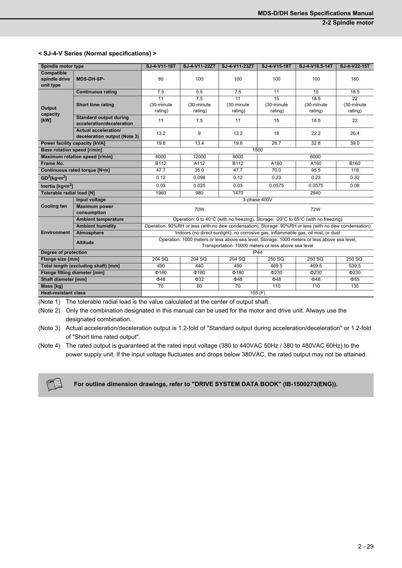
MDS-D/DH Series Specifications Manual
2-2 Spindle motor
2 - 29
< SJ-4-V Series (Normal specifications) >
(Note 1) The tolerable radial load is the value calculated at the center of output shaft.
(Note 2) Only the combination designated in this manual can be used for the motor and drive unit. Always use the
designated combination.
(Note 3) Actual acceleration/deceleration output is 1.2-fold of "Standard output during acceleration/deceleration" or 1.2-fold
of "Short time rated output".
(Note 4) The rated output is guaranteed at the rated input voltage (380 to 440VAC 50Hz / 380 to 480VAC 60Hz) to the
power supply unit. If the input voltage fluctuates and drops below 380VAC, the rated output may not be attained.
Spindle motor type SJ-4-V11-18T SJ-4-V11-22ZT SJ-4-V11-23ZT SJ-4-V15-18T SJ-4-V18.5-14T SJ-4-V22-15T
Compatible spindle drive unit type
MDS-DH-SP- 80 100 100 100 100 160
Output capacity [kW]
Continuous rating 7.5 5.5 7.5 11 15 18.5
Short time rating11
(30-minute rating)
7.5(30-minute
rating)
11(30-minute
rating)
15(30-minute
rating)
18.5(30-minute
rating)
22(30-minute
rating)
Standard output duringacceleration/deceleration
11 7.5 11 15 18.5 22
Actual acceleration/deceleration output (Note 3)
13.2 9 13.2 18 22.2 26.4
Power facility capacity [kVA] 19.6 13.4 19.6 26.7 32.8 39.0
Base rotation speed [r/min] 1500
Maximum rotation speed [r/min] 6000 12000 8000 6000
Frame No. B112 A112 B112 A160 A160 B160
Continuous rated torque [N•m] 47.7 35.0 47.7 70.0 95.5 118
GD2[kg•m2] 0.12 0.098 0.12 0.23 0.23 0.32
Inertia [kg•m2] 0.03 0.025 0.03 0.0575 0.0575 0.08
Tolerable radial load [N] 1960 980 1470 2940
Cooling fanInput voltage 3-phase 400V
Maximum power consumption
70W 72W
Environment
Ambient temperature Operation: 0 to 40°C (with no freezing), Storage: -20°C to 65°C (with no freezing)
Ambient humidity Operation: 90%RH or less (with no dew condensation), Storage: 90%RH or less (with no dew condensation)
Atmosphere Indoors (no direct sunlight); no corrosive gas, inflammable gas, oil mist, or dust
AltitudeOperation: 1000 meters or less above sea level, Storage: 1000 meters or less above sea level,
Transportation: 10000 meters or less above sea level
Degree of protection IP44
Flange size [mm] 204 SQ. 204 SQ. 204 SQ. 250 SQ. 250 SQ. 250 SQ.
Total length (excluding shaft) [mm] 490 440 490 469.5 469.5 539.5
Flange fitting diameter [mm] Φ180 Φ180 Φ180 Φ230 Φ230 Φ230
Shaft diameter [mm] Φ48 Φ32 Φ48 Φ48 Φ48 Φ55
Mass [kg] 70 60 70 110 110 135
Heat-resistant class 155 (F)
For outline dimension drawings, refer to "DRIVE SYSTEM DATA BOOK" (IB-1500273(ENG)).

2 Specifications
MITSUBISHI CNC
2 - 30
< SJ-4-V Series (Normal specifications) >
(Note 1) The tolerable radial load is the value calculated at the center of output shaft.
(Note 2) Only the combination designated in this manual can be used for the motor and drive unit. Always use the
designated combination.
(Note 3) Actual acceleration/deceleration output is 1.2-fold of "Standard output during acceleration/deceleration" or 1.2-fold
of "Short time rated output".
(Note 4) The rated output is guaranteed at the rated input voltage (380 to 440VAC 50Hz / 380 to 480VAC 60Hz) to the
power supply unit. If the input voltage fluctuates and drops below 380VAC, the rated output may not be attained.
Spindle motor type SJ-4-V22-18ZT SJ-4-V26-08T SJ-4-V30-15ZT SJ-4-V37-04ZT SJ-4-V45-02T SJ-4-V55-03T
Compatible spindle drive unit type
MDS-DH-SP- 160 160 160 200 320 320
Output capacity [kW]
Continuous rating 11 22 18.5 30 37 45
Short time rating15
(30-minute rating)
26(30-minute
rating)
22(30-minute
rating)
37(30-minute
rating)
45(30-minute
rating)
55(30-minute
rating)
Standard output duringacceleration/deceleration
15 26 22 37 45 55
Actual acceleration/deceleration output (Note 3)
18 31.2 26.4 44.4 54 66
Power facility capacity [kVA] 26.7 46.1 39.0 65.5 79.6 97.2
Base rotation speed [r/min] 1500 1150 1500 1150
Maximum rotation speed [r/min] 8000 6000 8000 6000 4500 3450
Frame No. A160 C160 B160 B180 B180 A225
Continuous rated torque [N•m] 70.0 140 118 249 236 374
GD2[kg•m2] 0.23 0.38 0.32 1.36 1.36 3.39
Inertia [kg•m2] 0.0575 0.0925 0.08 0.34 0.34 0.85
Tolerable radial load [N] 2940 1960 3920 5880
Cooling fanInput voltage 3-phase 400V
Maximum power consumption
72W Refer to each motor specifications.
Environment
Ambient temperature Operation: 0 to 40°C (with no freezing), Storage: -20°C to 65°C (with no freezing)
Ambient humidity Operation: 90%RH or less (with no dew condensation), Storage: 90%RH or less (with no dew condensation)
Atmosphere Indoors (no direct sunlight); no corrosive gas, inflammable gas, oil mist, or dust
AltitudeOperation: 1000 meters or less above sea level, Storage: 1000 meters or less above sea level,
Transportation: 10000 meters or less above sea level
Degree of protection IP44
Flange size [mm] 250 SQ. 250 SQ. 250 SQ. 320 SQ. 320 SQ. 480 SQ.
Total length (excluding shaft) [mm] 469.5 585.5 539.5 700 700 724
Flange fitting diameter [mm] Φ230 Φ230 Φ230 Φ300 Φ300 Φ450
Shaft diameter [mm] Φ48 Φ55 Φ55 Φ60 Φ60 Φ75
Mass [kg] 110 155 155 300 300 450
Heat-resistant class 155 (F)
For outline dimension drawings, refer to "DRIVE SYSTEM DATA BOOK" (IB-1500273(ENG)).
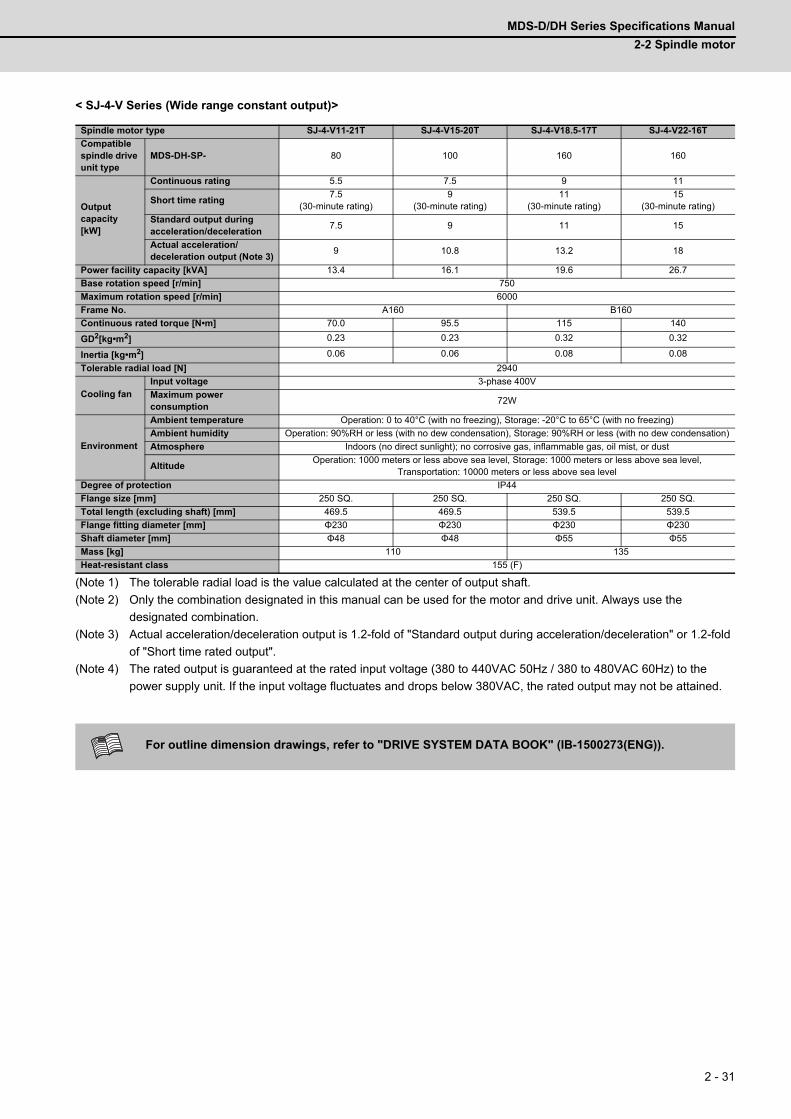
MDS-D/DH Series Specifications Manual
2-2 Spindle motor
2 - 31
< SJ-4-V Series (Wide range constant output)>
(Note 1) The tolerable radial load is the value calculated at the center of output shaft.
(Note 2) Only the combination designated in this manual can be used for the motor and drive unit. Always use the
designated combination.
(Note 3) Actual acceleration/deceleration output is 1.2-fold of "Standard output during acceleration/deceleration" or 1.2-fold
of "Short time rated output".
(Note 4) The rated output is guaranteed at the rated input voltage (380 to 440VAC 50Hz / 380 to 480VAC 60Hz) to the
power supply unit. If the input voltage fluctuates and drops below 380VAC, the rated output may not be attained.
Spindle motor type SJ-4-V11-21T SJ-4-V15-20T SJ-4-V18.5-17T SJ-4-V22-16T
Compatible spindle drive unit type
MDS-DH-SP- 80 100 160 160
Output capacity [kW]
Continuous rating 5.5 7.5 9 11
Short time rating7.5
(30-minute rating)9
(30-minute rating)11
(30-minute rating)15
(30-minute rating)
Standard output duringacceleration/deceleration
7.5 9 11 15
Actual acceleration/deceleration output (Note 3)
9 10.8 13.2 18
Power facility capacity [kVA] 13.4 16.1 19.6 26.7
Base rotation speed [r/min] 750
Maximum rotation speed [r/min] 6000
Frame No. A160 B160
Continuous rated torque [N•m] 70.0 95.5 115 140
GD2[kg•m2] 0.23 0.23 0.32 0.32
Inertia [kg•m2] 0.06 0.06 0.08 0.08
Tolerable radial load [N] 2940
Cooling fanInput voltage 3-phase 400V
Maximum power consumption
72W
Environment
Ambient temperature Operation: 0 to 40°C (with no freezing), Storage: -20°C to 65°C (with no freezing)
Ambient humidity Operation: 90%RH or less (with no dew condensation), Storage: 90%RH or less (with no dew condensation)
Atmosphere Indoors (no direct sunlight); no corrosive gas, inflammable gas, oil mist, or dust
AltitudeOperation: 1000 meters or less above sea level, Storage: 1000 meters or less above sea level,
Transportation: 10000 meters or less above sea level
Degree of protection IP44
Flange size [mm] 250 SQ. 250 SQ. 250 SQ. 250 SQ.
Total length (excluding shaft) [mm] 469.5 469.5 539.5 539.5
Flange fitting diameter [mm] Φ230 Φ230 Φ230 Φ230
Shaft diameter [mm] Φ48 Φ48 Φ55 Φ55
Mass [kg] 110 135
Heat-resistant class 155 (F)
For outline dimension drawings, refer to "DRIVE SYSTEM DATA BOOK" (IB-1500273(ENG)).
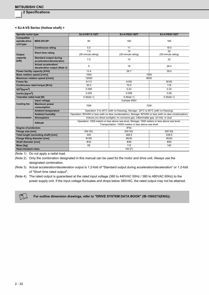
2 Specifications
MITSUBISHI CNC
2 - 32
< SJ-4-VS Series (Hollow shaft) >
(Note 1) Do not apply a radial load.
(Note 2) Only the combination designated in this manual can be used for the motor and drive unit. Always use the
designated combination.
(Note 3) Actual acceleration/deceleration output is 1.2-fold of "Standard output during acceleration/deceleration" or 1.2-fold
of "Short time rated output".
(Note 4) The rated output is guaranteed at the rated input voltage (380 to 440VAC 50Hz / 380 to 480VAC 60Hz) to the
power supply unit. If the input voltage fluctuates and drops below 380VAC, the rated output may not be attained.
Spindle motor type SJ-4-VS7.5-13ZT SJ-4-VS22-18ZT SJ-4-VS30-15ZT
Compatible spindle drive unit type
MDS-DH-SP- 80 160 160
Output capacity [kW]
Continuous rating 5.5 11 18.5
Short time rating7.5
(30-minute rating)15
(30-minute rating)22
(30-minute rating)
Standard output duringacceleration/deceleration
7.5 15 22
Actual acceleration/deceleration output (Note 3)
9 18 26.4
Power facility capacity [kVA] 13.4 26.7 39.0
Base rotation speed [r/min] 1500 1500
Maximum rotation speed [r/min] 12000 8000
Frame No. A112 A160 B160
Continuous rated torque [N•m] 35.0 70.0 118
GD2[kg•m2] 0.099 0.23 0.32
Inertia [kg•m2] 0.025 0.058 0.08
Tolerable radial load [N] 0 (Note 1) 0 (Note 1) 0 (Note 1)
Cooling fanInput voltage 3-phase 400V
Maximum power consumption
70W 72W
Environment
Ambient temperature Operation: 0 to 40°C (with no freezing), Storage: -20°C to 65°C (with no freezing)
Ambient humidity Operation: 90%RH or less (with no dew condensation), Storage: 90%RH or less (with no dew condensation)
Atmosphere Indoors (no direct sunlight); no corrosive gas, inflammable gas, oil mist, or dust
AltitudeOperation: 1000 meters or less above sea level, Storage: 1000 meters or less above sea level,
Transportation: 10000 meters or less above sea level
Degree of protection IP44
Flange size [mm] 204 SQ. 250 SQ. 250 SQ.
Total length (excluding shaft) [mm] 440 469.5 539.5
Flange fitting diameter [mm] Φ180 Φ230 Φ230
Shaft diameter [mm] Φ32 Φ48 Φ55
Mass [kg] 65 115 140
Heat-resistant class 155 (F)
For outline dimension drawings, refer to "DRIVE SYSTEM DATA BOOK" (IB-1500273(ENG)).
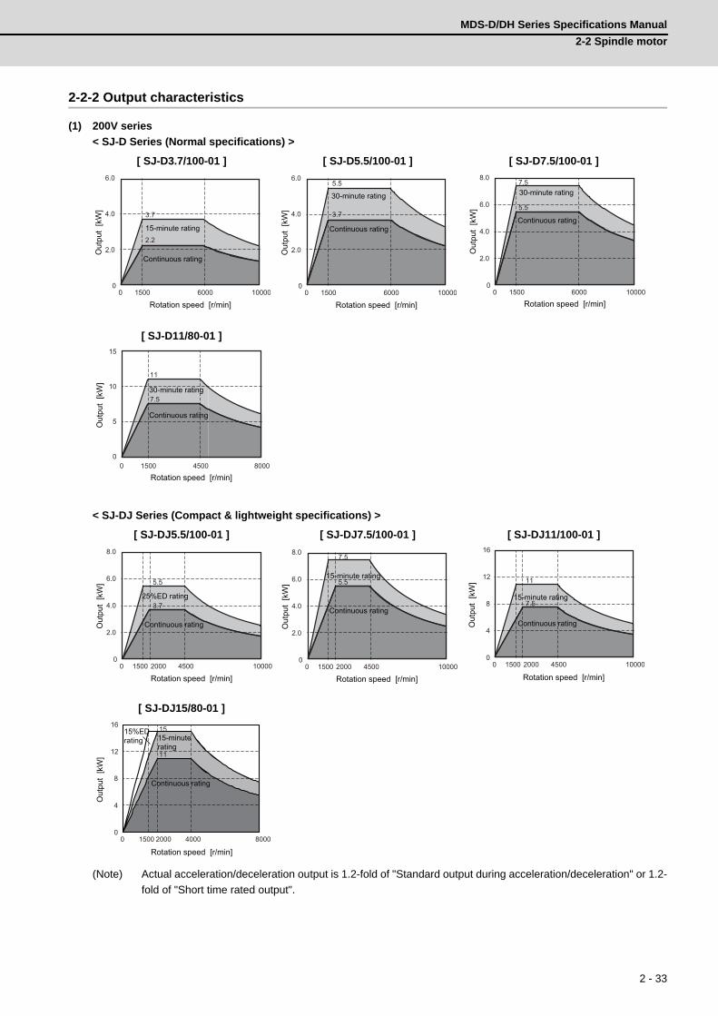
MDS-D/DH Series Specifications Manual
2-2 Spindle motor
2 - 33
2-2-2 Output characteristics
(1) 200V series
< SJ-D Series (Normal specifications) >
< SJ-DJ Series (Compact & lightweight specifications) >
(Note) Actual acceleration/deceleration output is 1.2-fold of "Standard output during acceleration/deceleration" or 1.2-
fold of "Short time rated output".
[ SJ-D3.7/100-01 ] [ SJ-D5.5/100-01 ] [ SJ-D7.5/100-01 ]
[ SJ-D11/80-01 ]
[ SJ-DJ5.5/100-01 ] [ SJ-DJ7.5/100-01 ] [ SJ-DJ11/100-01 ]
[ SJ-DJ15/80-01 ]
0 1500 6000 10000
6.0
4.0
2.0
0
2.2
3.7
Continuous rating
15-minute rating
Rotation speed [r/min]
Out
put
[kW
]
0 1500 6000 10000
3.7
6.0
4.0
2.0
0
5.5
Continuous rating
30-minute rating
Rotation speed [r/min]
Out
put
[kW
]0 1500 10000
5.5
8.0
6.0
4.0
2.0
0
7.5
6000
Continuous rating
30-minute rating
Rotation speed [r/min]
Out
put
[kW
]0 1500 4500 8000
Continuous rating
30-minute rating
Rotation speed [r/min]
Out
put
[kW
]
0 1500 10000
5.5
8.0
6.0
4.0
2.0
0
3.7
45002000
Continuous rating
25%ED rating
Rotation speed [r/min]
Out
put
[kW
]
0 1500 10000
5.5
8.0
6.0
4.0
2.0
0
7.5
45002000
Continuous rating
15-minute rating
Rotation speed [r/min]
Out
put
[kW
]
0 1500 10000
11
16
12
8
4
0
7.5
45002000
Continuous rating
15-minute rating
Rotation speed [r/min]
Out
put
[kW
]
0 1500 8000
11
16
12
8
4
0
15
2000 4000
Continuous rating
15-minute rating
Rotation speed [r/min]
Out
put
[kW
]
15%ED rating
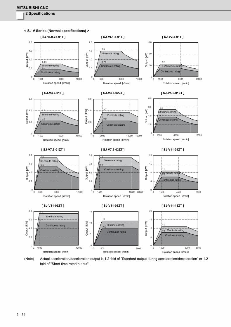
2 Specifications
MITSUBISHI CNC
2 - 34
< SJ-V Series (Normal specifications) >
(Note) Actual acceleration/deceleration output is 1.2-fold of "Standard output during acceleration/deceleration" or 1.2-
fold of "Short time rated output".
[ SJ-VL0.75-01T ] [ SJ-VL1.5-01T ] [ SJ-V2.2-01T ]
[ SJ-V3.7-01T ] [ SJ-V3.7-02ZT ] [ SJ-V5.5-01ZT ]
[ SJ-V7.5-01ZT ] [ SJ-V7.5-03ZT ] [ SJ-V11-01ZT ]
[ SJ-V11-06ZT ] [ SJ-V11-08ZT ] [ SJ-V11-13ZT ]
0 1500 6000 10000
0.4
2.0
1.5
1.0
0.5
0
0.75
Continuous rating
10-minute rating
Rotation speed [r/min]
Out
put
[kW
]
0 1500 6000 10000
1.5
2.0
1.5
1.0
0.5
0
0.75
Continuous rating
10-minute rating
Rotation speed [r/min]O
utpu
t [k
W]
0 1500 6000 10000
1.5
6.0
4.0
2.0
0
2.2
Continuous rating
15-minute rating
Rotation speed [r/min]
Out
put
[kW
]
0 1500 6000 10000
3.7
6.0
4.0
2.0
0
2.2
Continuous rating
15-minute rating
Rotation speed [r/min]
Out
put
[kW
]
0 3000 12000 15000
3.7
6.0
4.0
2.0
0
2.2
Continuous rating
15-minute rating
Rotation speed [r/min]
Out
put
[kW
]
0 1500 6000 12000
5.5
8.0
6.0
4.0
2.0
0
3.7
Continuous rating
30-minute rating
Rotation speed [r/min]
Out
put
[kW
]
0 1500 6000 12000
5.5
8.0
6.0
4.0
2.0
0
7.5
Continuous rating
30-minute rating
Rotation speed [r/min]
Out
put
[kW
]
0 1500 10000 12000
5.5
8.0
6.0
4.0
2.0
0
7.5
Continuous rating
30-minute rating
Rotation speed [r/min]
Out
put
[kW
]
0 1500 4500 8000
11
7.5
20
15
10
5
0
Continuous rating
30-minute rating
Rotation speed [r/min]
Out
put
[kW
]
0 1500 12000
5.5
8.0
6.0
4.0
2.0
0
7.5
Continuous rating
30-minute rating
Rotation speed [r/min]
Out
put
[kW
]
0 1500 8000
7.5
11
15
10
5
0
Continuous rating
30-minute rating
Rotation speed [r/min]
Out
put
[kW
]
0 1500 6000 8000
11
7.5
20
15
10
5
0
Continuous rating
30-minute rating
Rotation speed [r/min]
Out
put
[kW
]
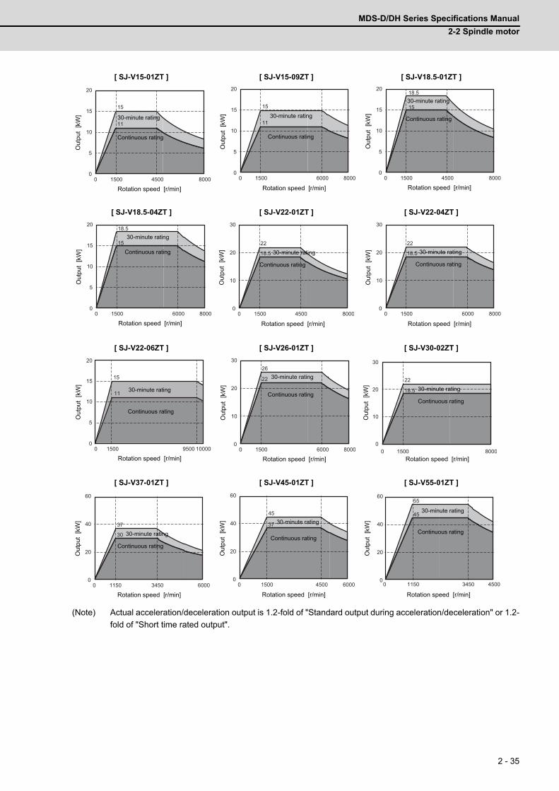
MDS-D/DH Series Specifications Manual
2-2 Spindle motor
2 - 35
(Note) Actual acceleration/deceleration output is 1.2-fold of "Standard output during acceleration/deceleration" or 1.2-
fold of "Short time rated output".
[ SJ-V15-01ZT ] [ SJ-V15-09ZT ] [ SJ-V18.5-01ZT ]
[ SJ-V18.5-04ZT ] [ SJ-V22-01ZT ] [ SJ-V22-04ZT ]
[ SJ-V22-06ZT ] [ SJ-V26-01ZT ] [ SJ-V30-02ZT ]
[ SJ-V37-01ZT ] [ SJ-V45-01ZT ] [ SJ-V55-01ZT ]
0 1500 4500 8000
11
15
20
15
10
5
0
Continuous rating
30-minute rating
Rotation speed [r/min]
Out
put
[kW
]
0 1500 6000 8000
11
15
20
15
10
5
0
Continuous rating
30-minute rating
Rotation speed [r/min]
Out
put
[kW
]
0 1500 4500 8000
15
18.520
15
10
5
0
Continuous rating
30-minute rating
Rotation speed [r/min]
Out
put
[kW
]
0 1500 6000 8000
18.5
15
20
15
10
5
0
Continuous rating
30-minute rating
Rotation speed [r/min]
Out
put
[kW
]
0 1500 4500 8000
18.5
22
30
20
10
0
Continuous rating
30-minute rating
Rotation speed [r/min]
Out
put
[kW
]
0 1500 6000 8000
18.5
22
30
20
10
0
Continuous rating
30-minute rating
Rotation speed [r/min]
Out
put
[kW
]
0 1500 10000
20
15
10
5
0
15
9500
11
Continuous rating
30-minute rating
Rotation speed [r/min]
Out
put
[kW
]
0 1500 6000 8000
26
22
30
20
10
0
Continuous rating
30-minute rating
Rotation speed [r/min]
Out
put
[kW
]
0 1500 8000
18.5
22
30
20
10
0
Continuous rating
30-minute rating
Rotation speed [r/min]
Out
put
[kW
]
0 1150 3450 6000
30
37
60
40
20
0
Continuous rating
30-minute rating
Rotation speed [r/min]
Out
put
[kW
]
0 1500 4500 6000
45
37
60
40
20
0
Continuous rating
30-minute rating
Rotation speed [r/min]
Out
put
[kW
]
0 1150 3450 4500
45
5560
40
20
0
Continuous rating
30-minute rating
Rotation speed [r/min]
Out
put
[kW
]

2 Specifications
MITSUBISHI CNC
2 - 36
< SJ-V Series (Wide range constant output) >
(Note) Actual acceleration/deceleration output is 1.2-fold of "Standard output during acceleration/deceleration" or 1.2-
fold of "Short time rated output".
[ SJ-V11-01T ] [ SJ-V11-09T ] [ SJ-V15-03T ]
[ SJ-V18.5-03T ] [ SJ-V22-05T ] [ SJ-V22-09T ]
[ SJ-VK22-19ZT (in low-speed coil) ] [ SJ-VK22-19ZT (in high-speed coil) ]
0 750 6000
5.5
3.7
15
10
5
0
Continuous rating
30-minute rating
Rotation speed [r/min]
Out
put
[kW
]
0 750 6000
5.5
7.5
15
10
5
0
Continuous rating
30-minute rating
Rotation speed [r/min]O
utpu
t [k
W]
0 750 6000
97.5
15
10
5
0
Continuous rating
30-minute rating
Rotation speed [r/min]
Out
put
[kW
]
0 750 6000
911
20
15
10
5
0
Continuous rating
30-minute rating
Rotation speed [r/min]
Out
put
[kW
]
0 750 6000
15
11
20
15
10
5
0
Continuous rating
30-minute rating
Rotation speed [r/min]
Out
put
[kW
]
600 3500 4500
15
18.5
30
20
10
05000
Continuous rating
30-minute rating
Rotation speed [r/min]
Out
put
[kW
]
0 330 750
30
20
10
0
18.5
400
13Continuous rating
10-minute rating
Rotation speed [r/min]
Out
put
[kW
]
15-minute rating
0 575 3450 6000
18.5
22
30
20
10
0
Continuous rating
30-minute rating
Rotation speed [r/min]
Out
put
[kW
]
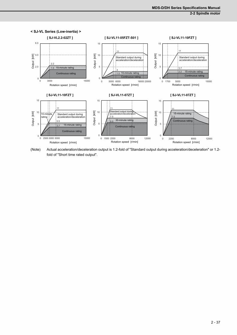
MDS-D/DH Series Specifications Manual
2-2 Spindle motor
2 - 37
< SJ-VL Series (Low-inertia) >
(Note) Actual acceleration/deceleration output is 1.2-fold of "Standard output during acceleration/deceleration" or 1.2-
fold of "Short time rated output".
[ SJ-VL2.2-02ZT ] [ SJ-VL11-05FZT-S01 ] [ SJ-VL11-10FZT ]
[ SJ-VL11-10FZT ] [ SJ-VL11-07ZT ] [ SJ-VL11-07ZT ]
0 3000 15000
1.5
6.0
4.0
2.0
0
2.2
Continuous rating
15-minute rating
Rotation speed [r/min]
Out
put
[kW
]
0 5000 20000
11
15
10
5
0
3
18000
1.5
6000
Continuous rating10-minute rating
Rotation speed [r/min]
Out
put
[kW
]
Standard output duringacceleration/deceleration
0 1700 15000
11
15
10
5
0
3.7
5000
2.2
Continuous rating15-minute rating
Rotation speed [r/min]
Out
put
[kW
]
Standard output duringacceleration/deceleration
0 2500 15000
11
15
10
5
0
5.5
5000
3.7
3000
Continuous rating
10-minute rating
Rotation speed [r/min]
Out
put
[kW
]
15-minute rating
Standard output duringacceleration/deceleration
0 1500 12000
11
15
10
5
0
7.5
8000
5.5
2200
Continuous rating
30-minute rating
Rotation speed [r/min]
Out
put
[kW
] Standard output during acceleration/deceleration
0 2200 8000 12000
11
15
10
5
0
7.5
Continuous rating
15-minute rating
Rotation speed [r/min]
Out
put
[kW
]
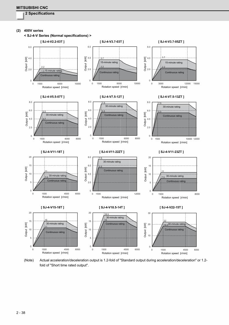
2 Specifications
MITSUBISHI CNC
2 - 38
(2) 400V series
< SJ-4-V Series (Normal specifications) >
(Note) Actual acceleration/deceleration output is 1.2-fold of "Standard output during acceleration/deceleration" or 1.2-
fold of "Short time rated output".
[ SJ-4-V2.2-03T ] [ SJ-4-V3.7-03T ] [ SJ-4-V3.7-05ZT ]
[ SJ-4-V5.5-07T ] [ SJ-4-V7.5-12T ] [ SJ-4-V7.5-13ZT ]
[ SJ-4-V11-18T ] [ SJ-4-V11-22ZT ] [ SJ-4-V11-23ZT ]
[ SJ-4-V15-18T ] [ SJ-4-V18.5-14T ] [ SJ-4-V22-15T ]
0 1500 6000 10000
1.5
6.0
4.0
2.0
0
2.2
Continuous rating
15-minute rating
Rotation speed [r/min]
Out
put
[kW
]
0 1500 6000 10000
3.7
6.0
4.0
2.02.2
0
Continuous rating
15-minute rating
Rotation speed [r/min]O
utpu
t [k
W]
0 3000 12000 15000
3.7
6.0
4.0
2.0
0
2.2
Continuous rating
15-minute rating
Rotation speed [r/min]
Out
put
[kW
]
0 1500 6000 8000
5.5
3.7
8.0
6.0
4.0
2.0
0
Continuous rating
30-minute rating
Rotation speed [r/min]
Out
put
[kW
]
0 1500 6000 8000
5.5
7.58.0
6.0
4.0
2.0
0
Continuous rating
30-minute rating
Rotation speed [r/min]
Out
put
[kW
]
0 1500 10000 12000
5.5
8.0
6.0
4.0
2.0
0
7.5
Continuous rating
30-minute rating
Rotation speed [r/min]O
utpu
t [k
W]
0 1500 6000
11
7.5
20
15
10
5
04500
Continuous rating
30-minute rating
Rotation speed [r/min]
Out
put
[kW
]
0 1500 12000
5.5
8.0
6.0
4.0
2.0
0
7.5
Continuous rating
30-minute rating
Rotation speed [r/min]
Out
put
[kW
]
0 1500 8000
11
7.5
20
15
10
5
0
Continuous rating
30-minute rating
Rotation speed [r/min]
Out
put
[kW
]
0 1500 6000
11
15
20
15
10
5
04500
Continuous rating
30-minute rating
Rotation speed [r/min]
Out
put
[kW
]
0 1500 6000
15
18.520
15
10
5
04500
Continuous rating
30-minute rating
Rotation speed [r/min]
Out
put
[kW
]
0 1500 4500 6000
18.5
22
30
20
10
0
Continuous rating
30-minute rating
Rotation speed [r/min]
Out
put
[kW
]

MDS-D/DH Series Specifications Manual
2-2 Spindle motor
2 - 39
(Note) Actual acceleration/deceleration output is 1.2-fold of "Standard output during acceleration/deceleration" or 1.2-
fold of "Short time rated output".
[ SJ-4-V22-18ZT ] [ SJ-4-V26-08T ] [ SJ-4-V30-15ZT ]
[ SJ-4-V37-04ZT ] [ SJ-4-V45-02T ] [ SJ-4-V55-03T ]
0 1500 8000
11
15
20
15
10
5
0
Continuous rating
30-minute rating
Rotation speed [r/min]
Out
put
[kW
]
0 1500 6000
26
22
30
20
10
0
Continuous rating
30-minute rating
Rotation speed [r/min]
Out
put
[kW
]
0 1500 8000
18.5
22
30
20
10
0
Continuous rating
30-minute rating
Rotation speed [r/min]
Out
put
[kW
]
0 1150 3450
30
37
60
40
20
06000
Continuous rating
30-minute rating
Rotation speed [r/min]
Out
put
[kW
]
0 1500 4500
45
37
60
40
20
0
Continuous rating
30-minute rating
Rotation speed [r/min]
Out
put
[kW
]
0 1150 3450
45
5560
40
20
0
Continuous rating
30-minute rating
Rotation speed [r/min]
Out
put
[kW
]

2 Specifications
MITSUBISHI CNC
2 - 40
< SJ-4-V Series (Wide range constant output) >
< SJ-4-VS Series (Hollow shaft) >
(Note) Actual acceleration/deceleration output is 1.2-fold of "Standard output during acceleration/deceleration" or 1.2-
fold of "Short time rated output".
[ SJ-4-V11-21T ] [ SJ-4-V15-20T ] [ SJ-4-V18.5-17T ]
[ SJ-4-V22-16T ]
[ SJ-4-VS7.5-13ZT ] [ SJ-4-VS22-18ZT ] [ SJ-4-VS30-15ZT ]
0 750 6000
5.5
7.5
15
10
5
0
Continuous rating
30-minute rating
Rotation speed [r/min]
Out
put
[kW
]
0 750 6000
7.59
15
10
5
0
Continuous rating30-minute rating
Rotation speed [r/min]O
utpu
t [k
W]
0 750 6000
119
20
15
10
5
0
Continuous rating
30-minute rating
Rotation speed [r/min]
Out
put
[kW
]
0 750 6000
11
15
20
15
10
5
0
Continuous rating
30-minute rating
Rotation speed [r/min]
Out
put
[kW
]
0 1500 12000
5.5
8.0
6.0
4.0
2.0
0
7.5
Continuous rating
30-minute rating
Rotation speed [r/min]
Out
put
[kW
]
0 1500 8000
11
15
20
15
10
5
0
Continuous rating
30-minute rating
Rotation speed [r/min]
Out
put
[kW
]
0 1500 8000
18.5
22
30
20
10
0
Continuous rating
30-minute rating
Rotation speed [r/min]
Out
put
[kW
]
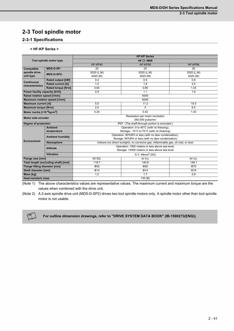
MDS-D/DH Series Specifications Manual
2-3 Tool spindle motor
2 - 41
2-3 Tool spindle motor2-3-1 Specifications
< HF-KP Series >
(Note 1) The above characteristics values are representative values. The maximum current and maximum torque are the
values when combined with the drive unit.
(Note 2) A 2-axis spindle drive unit (MDS-D-SP2) drives two tool spindle motors only. A spindle motor other than tool spindle
motor is not usable.
Tool spindle motor type
HF-KP Series
HF -W09
HF-KP46 HF-KP56 HF-KP96
Compatible spindle drive unit type
MDS-D-SP- 20 20 20
MDS-D-SP2-2020 (L,M)4020 (M)
2020 (L,M)4020 (M)
2020 (L,M)4020 (M)
Continuous characteristics
Rated output [kW] 0.4 0.5 0.9
Rated current [A] 1.5 1.8 3.4
Rated torque [N•m] 0.64 0.80 1.43
Power facility capacity [kVA] 0.9 1.1 1.8
Rated rotation speed [r/min] 6000
Maximum rotation speed [r/min] 6000
Maximum current [A] 5.5 11.3 15.5
Maximum torque [N•m] 2.5 5 6.5
Motor inertia [×10-4kg•m2] 0.24 0.42 1.43
Motor side encoderResolution per motor revolution
260,000 pulse/rev
Degree of protection IP67 (The shaft-through portion is excluded.)
Environment
Ambient temperature
Operation: 0 to 40°C (with no freezing),Storage: -15°C to 70°C (with no freezing)
Ambient humidityOperation: 80%RH or less (with no dew condensation),
Storage: 90%RH or less (with no dew condensation)
Atmosphere Indoors (no direct sunlight); no corrosive gas, inflammable gas, oil mist, or dust
AltitudeOperation: 1000 meters or less above sea level,Storage: 10000 meters or less above sea level
Vibration X,Y: 49m/s2 (5G)
Flange size [mm] 60 SQ. 60 SQ. 80 SQ.
Total length (excluding shaft) [mm] 118.7 140.6 149.1
Flange fitting diameter [mm] Φ50 Φ50 Φ70
Shaft diameter [mm] Φ14 Φ14 Φ19
Mass [kg] 1.2 1.7 2.9
Heat-resistant class 130 (B)
For outline dimension drawings, refer to "DRIVE SYSTEM DATA BOOK" (IB-1500273(ENG)).
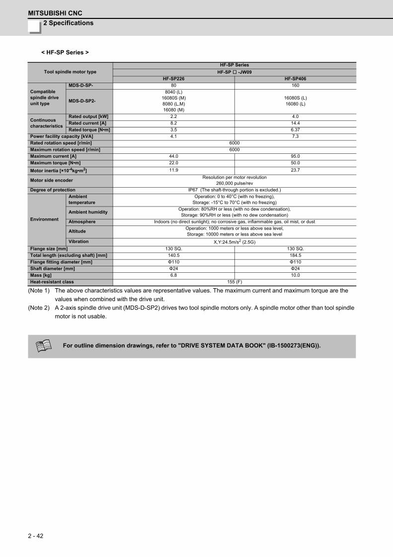
2 Specifications
MITSUBISHI CNC
2 - 42
< HF-SP Series >
(Note 1) The above characteristics values are representative values. The maximum current and maximum torque are the
values when combined with the drive unit.
(Note 2) A 2-axis spindle drive unit (MDS-D-SP2) drives two tool spindle motors only. A spindle motor other than tool spindle
motor is not usable.
Tool spindle motor type
HF-SP Series
HF-SP -JW09
HF-SP226 HF-SP406
Compatible spindle drive unit type
MDS-D-SP- 80 160
MDS-D-SP2-
8040 (L)16080S (M)8080 (L,M)16080 (M)
16080S (L)16080 (L)
Continuous characteristics
Rated output [kW] 2.2 4.0
Rated current [A] 8.2 14.4
Rated torque [N•m] 3.5 6.37
Power facility capacity [kVA] 4.1 7.3
Rated rotation speed [r/min] 6000
Maximum rotation speed [r/min] 6000
Maximum current [A] 44.0 95.0
Maximum torque [N•m] 22.0 50.0
Motor inertia [×10-4kg•m2] 11.9 23.7
Motor side encoderResolution per motor revolution
260,000 pulse/rev
Degree of protection IP67 (The shaft-through portion is excluded.)
Environment
Ambient temperature
Operation: 0 to 40°C (with no freezing),Storage: -15°C to 70°C (with no freezing)
Ambient humidityOperation: 80%RH or less (with no dew condensation),
Storage: 90%RH or less (with no dew condensation)
Atmosphere Indoors (no direct sunlight); no corrosive gas, inflammable gas, oil mist, or dust
AltitudeOperation: 1000 meters or less above sea level,Storage: 10000 meters or less above sea level
Vibration X,Y:24.5m/s2 (2.5G)
Flange size [mm] 130 SQ. 130 SQ.
Total length (excluding shaft) [mm] 140.5 184.5
Flange fitting diameter [mm] Φ110 Φ110
Shaft diameter [mm] Φ24 Φ24
Mass [kg] 6.8 10.0
Heat-resistant class 155 (F)
For outline dimension drawings, refer to "DRIVE SYSTEM DATA BOOK" (IB-1500273(ENG)).
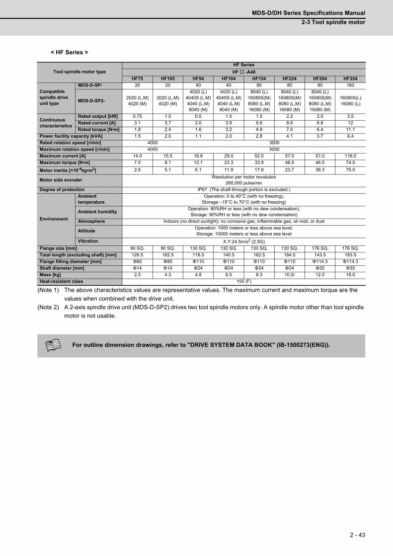
MDS-D/DH Series Specifications Manual
2-3 Tool spindle motor
2 - 43
< HF Series >
(Note 1) The above characteristics values are representative values. The maximum current and maximum torque are the
values when combined with the drive unit.
(Note 2) A 2-axis spindle drive unit (MDS-D-SP2) drives two tool spindle motors only. A spindle motor other than tool spindle
motor is not usable.
Tool spindle motor type
HF Series
HF -A48
HF75 HF105 HF54 HF104 HF154 HF224 HF204 HF354
Compatible spindle drive unit type
MDS-D-SP- 20 20 40 40 80 80 80 160
MDS-D-SP2-2020 (L,M)4020 (M)
2020 (L,M)4020 (M)
4020 (L)4040S (L,M)4040 (L,M)8040 (M)
4020 (L)4040S (L,M)4040 (L,M)8040 (M)
8040 (L)16080S(M)8080 (L,M)16080 (M)
8040 (L)16080S(M)8080 (L,M)16080 (M)
8040 (L)16080S(M)8080 (L,M)16080 (M)
16080S(L)16080 (L)
Continuous characteristics
Rated output [kW] 0.75 1.0 0.5 1.0 1.5 2.2 2.0 3.5
Rated current [A] 3.1 3.7 2.0 3.9 5.6 8.6 6.8 12
Rated torque [N•m] 1.8 2.4 1.6 3.2 4.8 7.0 6.4 11.1
Power facility capacity [kVA] 1.5 2.0 1.1 2.0 2.8 4.1 3.7 6.4
Rated rotation speed [r/min] 4000 3000
Maximum rotation speed [r/min] 4000 3000
Maximum current [A] 14.0 15.5 16.8 29.0 52.0 57.0 57.0 116.0
Maximum torque [N•m] 7.0 8.1 12.1 23.3 33.9 46.5 46.5 74.5
Motor inertia [×10-4kg•m2] 2.6 5.1 6.1 11.9 17.8 23.7 38.3 75.0
Motor side encoderResolution per motor revolution
260,000 pulse/rev
Degree of protection IP67 (The shaft-through portion is excluded.)
Environment
Ambient temperature
Operation: 0 to 40°C (with no freezing),Storage: -15°C to 70°C (with no freezing)
Ambient humidityOperation: 80%RH or less (with no dew condensation),
Storage: 90%RH or less (with no dew condensation)
Atmosphere Indoors (no direct sunlight); no corrosive gas, inflammable gas, oil mist, or dust
AltitudeOperation: 1000 meters or less above sea level,Storage: 10000 meters or less above sea level
Vibration X,Y:24.5m/s2 (2.5G)
Flange size [mm] 90 SQ. 90 SQ. 130 SQ. 130 SQ. 130 SQ. 130 SQ. 176 SQ. 176 SQ.
Total length (excluding shaft) [mm] 126.5 162.5 118.5 140.5 162.5 184.5 143.5 183.5
Flange fitting diameter [mm] Φ80 Φ80 Φ110 Φ110 Φ110 Φ110 Φ114.3 Φ114.3
Shaft diameter [mm] Φ14 Φ14 Φ24 Φ24 Φ24 Φ24 Φ35 Φ35
Mass [kg] 2.5 4.3 4.8 6.5 8.3 10.0/ 12.0 19.0
Heat-resistant class 155 (F)
For outline dimension drawings, refer to "DRIVE SYSTEM DATA BOOK" (IB-1500273(ENG)).
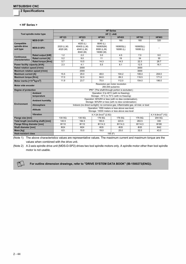
2 Specifications
MITSUBISHI CNC
2 - 44
< HF Series >
(Note 1) The above characteristics values are representative values. The maximum current and maximum torque are the
values when combined with the drive unit.
(Note 2) A 2-axis spindle drive unit (MDS-D-SP2) drives two tool spindle motors only. A spindle motor other than tool spindle
motor is not usable.
Tool spindle motor type
HF Series
HF -A48
HF123 HF223 HF303 HF453 HF703 HF903
Compatible spindle drive unit type
MDS-D-SP- 20 40 80 160 160 320
MDS-D-SP2-2020 (L,M)4020 (M)
4020 (L)4040S (L,M)4040 (L,M)8040 (M)
8040 (L)16080S(M)8080 (L,M)16080 (M)
16080S(L)16080 (L)
16080S(L)16080 (L)
-
Continuous characteristics
Rated output [kW] 1.2 2.2 3.0 4.5 7.0 9.0
Rated current [A] 5.2 9.0 11 19 34 30
Rated torque [N•m] 5.7 10.5 14.3 14.3 22.3 28.7
Power facility capacity [kVA] 2.3 4.1 5.5 8.1 12.5 16.1
Rated rotation speed [r/min] 2000 3000
Maximum rotation speed [r/min] 2000 3000
Maximum current [A] 15.5 29.0 48.0 104.2 108.4 204.0
Maximum torque [N•m] 17.0 32.0 64.0 89.3 116.5 171.0
Motor inertia [×10-4kg•m2] 11.9 23.7 75.0 112.0 154.0 196.0
Motor side encoderResolution per motor revolution
260,000 pulse/rev
Degree of protection IP67 (The shaft-through portion is excluded.)
Environment
Ambient temperature
Operation: 0 to 40°C (with no freezing),Storage: -15°C to 70°C (with no freezing)
Ambient humidityOperation: 80%RH or less (with no dew condensation),
Storage: 90%RH or less (with no dew condensation)
Atmosphere Indoors (no direct sunlight); no corrosive gas, inflammable gas, oil mist, or dust
AltitudeOperation: 1000 meters or less above sea level,Storage: 10000 meters or less above sea level
Vibration X,Y:24.5m/s2 (2.5G) X,Y:9.8m/s2 (1G)
Flange size [mm] 130 SQ. 130 SQ. 176 SQ. 176 SQ. 176 SQ. 204 SQ.
Total length (excluding shaft) [mm] 140.5 184.5 183.5 223.5 263.5 330
Flange fitting diameter [mm] Φ110 Φ110 Φ114.3 Φ114.3 Φ114.3 Φ180
Shaft diameter [mm] Φ24 Φ24 Φ35 Φ35 Φ35 Φ42
Mass [kg] 6.5 10.0 19.0 25.0 32.0 43.0
Heat-resistant class 155 (F)
For outline dimension drawings, refer to "DRIVE SYSTEM DATA BOOK" (IB-1500273(ENG)).
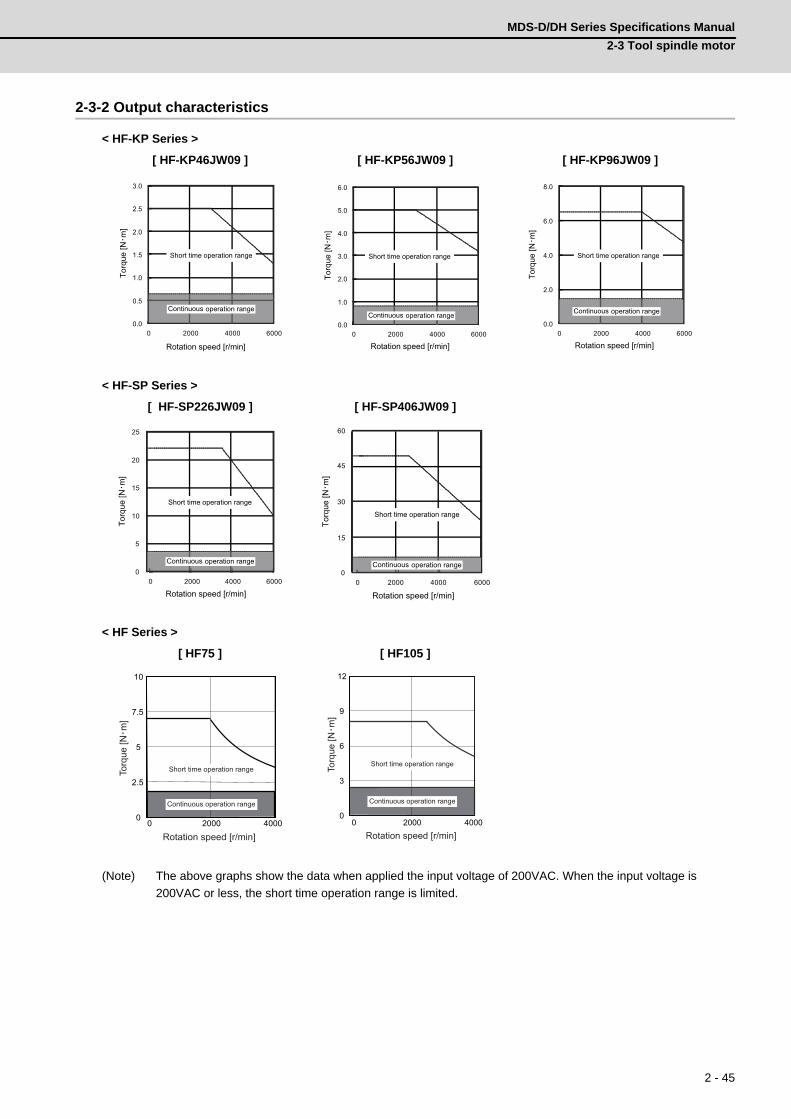
MDS-D/DH Series Specifications Manual
2-3 Tool spindle motor
2 - 45
2-3-2 Output characteristics
< HF-KP Series >
< HF-SP Series >
< HF Series >
(Note) The above graphs show the data when applied the input voltage of 200VAC. When the input voltage is
200VAC or less, the short time operation range is limited.
[ HF-KP46JW09 ] [ HF-KP56JW09 ] [ HF-KP96JW09 ]
[ HF-SP226JW09 ] [ HF-SP406JW09 ]
[ HF75 ] [ HF105 ]
0.0
0.5
1.0
1.5
2.0
2.5
3.0
0 2000 4000 6000
Torq
ue [N・m
]
Rotation speed [r/min]
Short time operation range
Continuous operation range
0.0
1.0
2.0
3.0
4.0
5.0
6.0
0 2000 4000 6000To
rque
[N・m
]
Rotation speed [r/min]
Short time operation range
Continuous operation range0.0
2.0
4.0
6.0
8.0
0 2000 4000 6000
Torq
ue [N・m
]
Rotation speed [r/min]
Short time operation range
Continuous operation range
0
5
10
15
20
25
0 2000 4000 6000
Torq
ue [N・m
]
Rotation speed [r/min]
Short time operation range
Continuous operation range0
15
30
45
60
0 2000 4000 6000
Torq
ue [N・m
]
Rotation speed [r/min]
Short time operation range
Continuous operation range
0 2000 0
2.5
5
7.5
10
4000
Rotation speed [r/min]
Torq
ue [N
m]
Short time operation range
Continuous operation range
0
3
6
9
12
0 2000 4000 Rotation speed [r/min]
Torq
ue [N
m]
Short time operation range
Continuous operation range
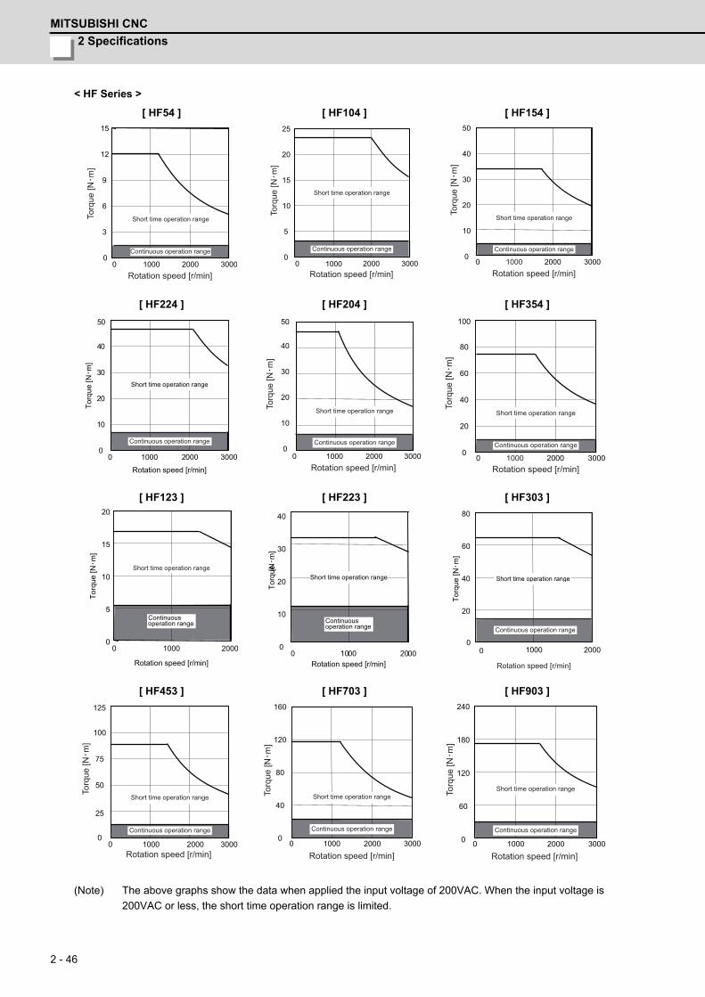
2 Specifications
MITSUBISHI CNC
2 - 46
< HF Series >
(Note) The above graphs show the data when applied the input voltage of 200VAC. When the input voltage is
200VAC or less, the short time operation range is limited.
[ HF54 ] [ HF104 ] [ HF154 ]
[ HF224 ] [ HF204 ] [ HF354 ]
[ HF123 ] [ HF223 ] [ HF303 ]
[ HF453 ] [ HF703 ] [ HF903 ]
0 2000 30000
3
9
12
15
6
1000Rotation speed [r/min]
Torq
ue [N
m]
Short time operation range
Continuous operation range
0 2000 30000
5
20
25
15
10
1000Rotation speed [r/min]
Torq
ue [N
m]
Short time operation range
Continuous operation range
0 2000 3000 0
10
40
50
30
20
1000Rotation speed [r/min]
Torq
ue [N
m]
Short time operation range
Continuous operation range
0 2000 30000
10
20
40
30
50
1000
Torq
ue [N・m
]
Rotation speed [r/min]
Short time operation range
Continuous operation range
0 2000 3000 0
10
20
40
30
50
1000Rotation speed [r/min]
Torq
ue [N
m]
Short time operation range
Continuous operation range
0 2000 3000 0
20
40
100
80
60
1000Rotation speed [r/min]
Torq
ue [N
m]
Short time operation range
Continuous operation range
0 1000 20000
5
10
15
20
Torq
ue [N・m
]
Rotation speed [r/min]
Continuousoperation range
Short time operation range
0 10000
10
20
30
40
2000Rotation speed [r/min]
[Nm
]To
rque
Continuousoperation range
Short time operation range
20
40
60
80
1000 200000
Torq
ue [N・m
]
Short time operation range
Continuous operation range
Rotation speed [r/min]
0 1000 0
25
100
125
75
50
2000 3000 Rotation speed [r/min]
Torq
ue [N
m]
Short time operation range
Continuous operation range
0 1000 3000 0
40
80
120
160
2000 Rotation speed [r/min]
Torq
ue [N
m]
Short time operation range
Continuous operation range
0
60
120
180
240
0 1000 3000 2000 Rotation speed [r/min]
Torq
ue [N
m]
Short time operation range
Continuous operation range
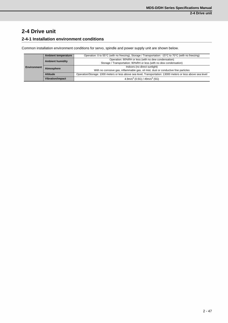
MDS-D/DH Series Specifications Manual
2-4 Drive unit
2 - 47
2-4 Drive unit2-4-1 Installation environment conditions
Common installation environment conditions for servo, spindle and power supply unit are shown below.
Environment
Ambient temperature Operation: 0 to 55°C (with no freezing), Storage / Transportation: -15°C to 70°C (with no freezing)
Ambient humidityOperation: 90%RH or less (with no dew condensation)
Storage / Transportation: 90%RH or less (with no dew condensation)
AtmosphereIndoors (no direct sunlight)
With no corrosive gas, inflammable gas, oil mist, dust or conductive fine particles
Altitude Operation/Storage: 1000 meters or less above sea level, Transportation: 13000 meters or less above sea level
Vibration/impact 4.9m/s2 (0.5G) / 49m/s2 (5G)
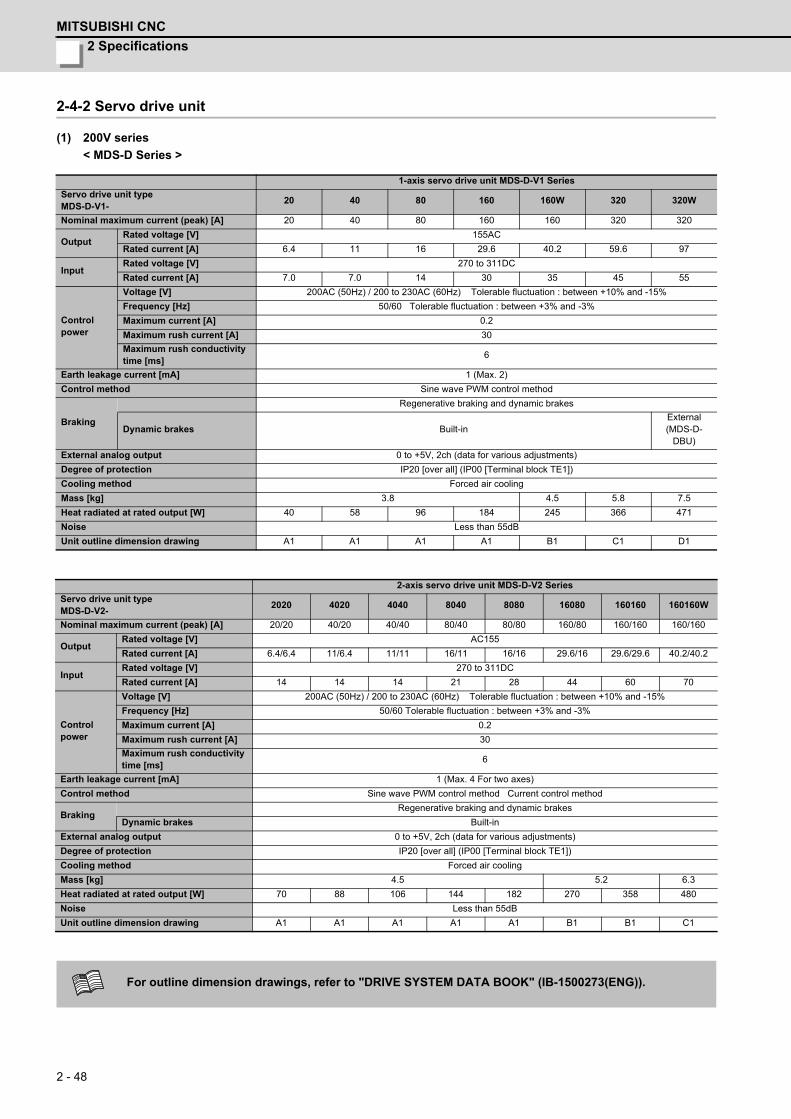
2 Specifications
MITSUBISHI CNC
2 - 48
2-4-2 Servo drive unit
(1) 200V series
< MDS-D Series >
1-axis servo drive unit MDS-D-V1 Series
Servo drive unit typeMDS-D-V1-
20 40 80 160 160W 320 320W
Nominal maximum current (peak) [A] 20 40 80 160 160 320 320
OutputRated voltage [V] 155AC
Rated current [A] 6.4 11 16 29.6 40.2 59.6 97
InputRated voltage [V] 270 to 311DC
Rated current [A] 7.0 7.0 14 30 35 45 55
Control power
Voltage [V] 200AC (50Hz) / 200 to 230AC (60Hz) Tolerable fluctuation : between +10% and -15%
Frequency [Hz] 50/60 Tolerable fluctuation : between +3% and -3%
Maximum current [A] 0.2
Maximum rush current [A] 30
Maximum rush conductivity time [ms]
6
Earth leakage current [mA] 1 (Max. 2)
Control method Sine wave PWM control method
Braking
Regenerative braking and dynamic brakes
Dynamic brakes Built-inExternal(MDS-D-
DBU)
External analog output 0 to +5V, 2ch (data for various adjustments)
Degree of protection IP20 [over all] (IP00 [Terminal block TE1])
Cooling method Forced air cooling
Mass [kg] 3.8 4.5 5.8 7.5
Heat radiated at rated output [W] 40 58 96 184 245 366 471
Noise Less than 55dB
Unit outline dimension drawing A1 A1 A1 A1 B1 C1 D1
2-axis servo drive unit MDS-D-V2 Series
Servo drive unit typeMDS-D-V2-
2020 4020 4040 8040 8080 16080 160160 160160W
Nominal maximum current (peak) [A] 20/20 40/20 40/40 80/40 80/80 160/80 160/160 160/160
OutputRated voltage [V] AC155
Rated current [A] 6.4/6.4 11/6.4 11/11 16/11 16/16 29.6/16 29.6/29.6 40.2/40.2
InputRated voltage [V] 270 to 311DC
Rated current [A] 14 14 14 21 28 44 60 70
Control power
Voltage [V] 200AC (50Hz) / 200 to 230AC (60Hz) Tolerable fluctuation : between +10% and -15%
Frequency [Hz] 50/60 Tolerable fluctuation : between +3% and -3%
Maximum current [A] 0.2
Maximum rush current [A] 30
Maximum rush conductivity time [ms]
6
Earth leakage current [mA] 1 (Max. 4 For two axes)
Control method Sine wave PWM control method Current control method
BrakingRegenerative braking and dynamic brakes
Dynamic brakes Built-in
External analog output 0 to +5V, 2ch (data for various adjustments)
Degree of protection IP20 [over all] (IP00 [Terminal block TE1])
Cooling method Forced air cooling
Mass [kg] 4.5 5.2 6.3
Heat radiated at rated output [W] 70 88 106 144 182 270 358 480
Noise Less than 55dB
Unit outline dimension drawing A1 A1 A1 A1 A1 B1 B1 C1
For outline dimension drawings, refer to "DRIVE SYSTEM DATA BOOK" (IB-1500273(ENG)).

MDS-D/DH Series Specifications Manual
2-4 Drive unit
2 - 49
(2) 400V series
< MDS-DH Series >
1-axis servo drive unit MDS-DH-V1 Series
Servo drive unit typeMDS-DH-V1-
10 20 40 80 80W 160 160W 200
Nominal maximum current (peak) [A] 10 20 40 80 80 160 160 200
OutputRated voltage [V] 340AC
Rated current [A] 2.3 3.9 7.3 17 20.1 32 46 76.8
InputRated voltage [V] 513 to 648DC
Rated current [A] 0.9 1.6 2.9 6.0 8.0 11.9 16.7 39
Control power
Voltage [V] 380 to 440AC (50Hz) / 380 to 480AC (60Hz) Tolerable fluctuation : between +10% and -15%
Frequency [Hz] 50/60 Tolerable fluctuation : between +3% and -3%
Maximum current [A] 0.1
Maximum rush current [A] 18
Maximum rush conductivity time [ms]
12 18
Earth leakage current [mA] 1 (Max. 2)
Control method Sine wave PWM control method
BrakingRegenerative braking and dynamic brakes
Dynamic brakes Built-in External (MDS-D-DBU)
External analog output 0 to +5V, 2ch (data for various adjustments)
Degree of protection IP20 [over all] (IP00 [Terminal block TE1])
Cooling method Forced air cooling
Mass [kg] 3.8 4.5 5.8 7.5 16.5
Heat radiated at rated output [W] 46 68 114 215 269 390 542 735
Noise Less than 55dB
Unit outline dimension drawing A1 A1 A1 A1 B1 C1 D1 E1
2-axis servo drive unit MDS-DH-V2 Series
Servo drive unit typeMDS-DH-V2-
1010 2010 2020 4020 4040 8040 8080 8080W
Nominal maximum current (peak) [A]
10/10 20/10 20/20 40/20 40/40 80/40 80/80 80/80
OutputRated voltage [V] 340AC
Rated current [A] 2.3 / 2.3 3.9 / 2.3 3.9 / 3.9 7.3 / 3.9 7.3 / 7.3 17 / 7.3 17 / 17 20.1 / 20.1
InputRated voltage [V] 513 to 648DC
Rated current [A] 1.8 2.5 3.2 4.5 5.8 8.9 12 16
Control power
Voltage [V] 380 to 440AC (50Hz) / 380 to 480AC (60Hz) Tolerable fluctuation : between +10% and -15%
Frequency [Hz] 50/60 Tolerable fluctuation : between +3% and -3%
Maximum current [A]
0.1
Maximum rush current [A]
18
Maximum rush conductivity time [ms]
12
Earth leakage current [mA] 1 (Max. 4 For two axes)
Control method Sine wave PWM control method Current control method
BrakingRegenerative braking and dynamic brakes
Dynamic brakes Built-in
External analog output 0 to +5V, 2ch (data for various adjustments)
Degree of protection IP20
Cooling method Forced air cooling
Mass [kg] 3.8 5.2 6.3
Heat radiated at rated output [W] 82 104 126 172 218 319 420 528
Noise Less than 55dB
Unit outline dimension drawing A1 A1 A1 A1 A1 B1 B1 C1
For outline dimension drawings, refer to "DRIVE SYSTEM DATA BOOK" (IB-1500273(ENG)).
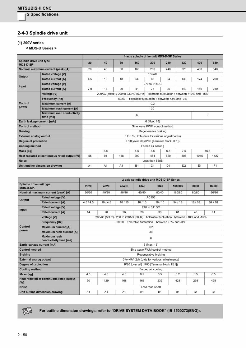
2 Specifications
MITSUBISHI CNC
2 - 50
2-4-3 Spindle drive unit
(1) 200V series
< MDS-D Series >
1-axis spindle drive unit MDS-D-SP Series
Spindle drive unit typeMDS-D-SP-
20 40 80 160 200 240 320 400 640
Nominal maximum current (peak) [A] 20 40 80 160 200 240 320 400 640
OutputRated voltage [V] 155AC
Rated current [A] 4.5 10 18 54 85 94 130 174 200
InputRated voltage [V] 270 to 311DC
Rated current [A] 7.0 13 20 41 76 95 140 150 210
Control power
Voltage [V] 200AC (50Hz) / 200 to 230AC (60Hz) Tolerable fluctuation : between +10% and -15%
Frequency [Hz] 50/60 Tolerable fluctuation : between +3% and -3%
Maximum current [A] 0.2
Maximum rush current [A] 30
Maximum rush conductivity time [ms]
6 9
Earth leakage current [mA] 6 (Max. 15)
Control method Sine wave PWM control method
Braking Regenerative braking
External analog output 0 to +5V, 2ch (data for various adjustments)
Degree of protection IP20 [over all] (IP00 [Terminal block TE1])
Cooling method Forced air cooling
Mass [kg] 3.8 4.5 5.8 6.5 7.5 16.5
Heat radiated at continuous rated output [W] 55 94 158 290 481 620 806 1045 1427
Noise Less than 55dB
Unit outline dimension drawing A1 A1 A1 B1 C1 D1 D2 E1 F1
2-axis spindle drive unit MDS-D-SP Series
Spindle drive unit typeMDS-D-SP-
2020 4020 4040S 4040 8040 16080S 8080 16080
Nominal maximum current (peak) [A] 20/20 40/20 40/40 40/40 80/40 160/80 80/80 160/80
OutputRated voltage [V] AC155
Rated current [A] 4.5 / 4.5 10 / 4.5 10 / 10 10 / 10 18 / 10 54 / 18 18 / 18 54 / 18
InputRated voltage [V] 270 to 311DC
Rated current [A] 14 20 26 26 33 61 40 61
Control power
Voltage [V] 200AC (50Hz) / 200 to 230AC (60Hz) Tolerable fluctuation : between +10% and -15%
Frequency [Hz] 50/60 Tolerable fluctuation : between +3% and -3%
Maximum current [A] 0.2
Maximum rush current [A] 30
Maximum rush conductivity time [ms]
6
Earth leakage current [mA] 6 (Max. 15)
Control method Sine wave PWM control method
Braking Regenerative braking
External analog output 0 to +5V, 2ch (data for various adjustments)
Degree of protection IP20 [over all] (IP00 [Terminal block TE1])
Cooling method Forced air cooling
Mass [kg] 4.5 4.5 4.5 6.5 6.5 5.2 6.5 6.5
Heat radiated at continuous rated output [W]
90 129 168 168 232 428 298 428
Noise Less than 55dB
Unit outline dimension drawing A1 A1 A1 B1 B1 B1 C1 C1
For outline dimension drawings, refer to "DRIVE SYSTEM DATA BOOK" (IB-1500273(ENG)).
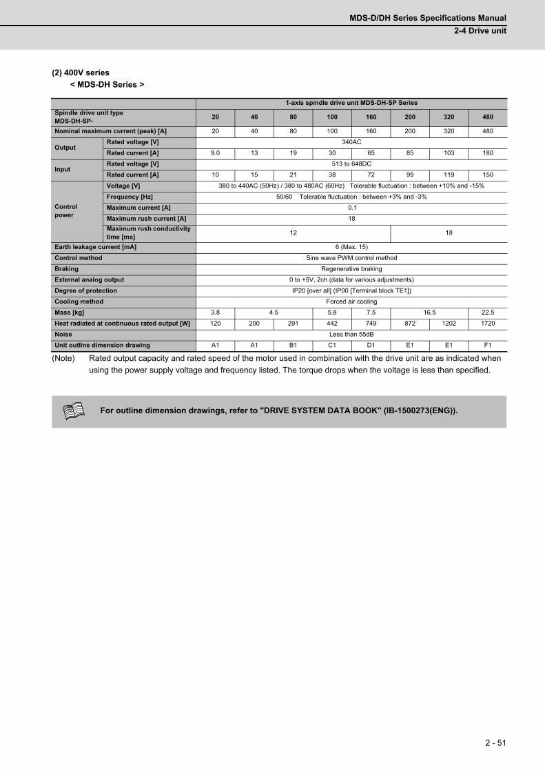
MDS-D/DH Series Specifications Manual
2-4 Drive unit
2 - 51
(2) 400V series
< MDS-DH Series >
(Note) Rated output capacity and rated speed of the motor used in combination with the drive unit are as indicated when
using the power supply voltage and frequency listed. The torque drops when the voltage is less than specified.
1-axis spindle drive unit MDS-DH-SP Series
Spindle drive unit typeMDS-DH-SP-
20 40 80 100 160 200 320 480
Nominal maximum current (peak) [A] 20 40 80 100 160 200 320 480
OutputRated voltage [V] 340AC
Rated current [A] 9.0 13 19 30 65 85 103 180
InputRated voltage [V] 513 to 648DC
Rated current [A] 10 15 21 38 72 99 119 150
Control power
Voltage [V] 380 to 440AC (50Hz) / 380 to 480AC (60Hz) Tolerable fluctuation : between +10% and -15%
Frequency [Hz] 50/60 Tolerable fluctuation : between +3% and -3%
Maximum current [A] 0.1
Maximum rush current [A] 18
Maximum rush conductivity time [ms]
12 18
Earth leakage current [mA] 6 (Max. 15)
Control method Sine wave PWM control method
Braking Regenerative braking
External analog output 0 to +5V, 2ch (data for various adjustments)
Degree of protection IP20 [over all] (IP00 [Terminal block TE1])
Cooling method Forced air cooling
Mass [kg] 3.8 4.5 5.8 7.5 16.5 22.5
Heat radiated at continuous rated output [W] 120 200 291 442 749 872 1202 1720
Noise Less than 55dB
Unit outline dimension drawing A1 A1 B1 C1 D1 E1 E1 F1
For outline dimension drawings, refer to "DRIVE SYSTEM DATA BOOK" (IB-1500273(ENG)).
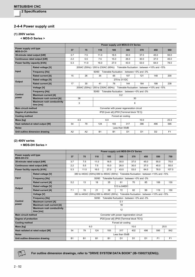
2 Specifications
MITSUBISHI CNC
2 - 52
2-4-4 Power supply unit
(1) 200V series
< MDS-D Series >
(2) 400V series
< MDS-DH Series >
Power supply unit MDS-D-CV Series
Power supply unit typeMDS-D-CV-
37 75 110 185 300 370 450 550
30-minute rated output [kW] 3.7 7.5 11.0 18.5 30.0 37.0 45.0 55.0
Continuous rated output [kW] 2.2 5.5 7.5 15.0 26.0 30.0 37.0 45.0
Power facility capacity [kVA] 5.3 11.0 16.0 27.0 43.0 53.0 64.0 78.0
Input
Rated voltage [V] 200AC (50Hz) / 200 to 230AC (60Hz) Tolerable fluctuation : between +10% and -15%
Frequency [Hz] 50/60 Tolerable fluctuation : between +3% and -3%
Rated current [A] 15 26 35 65 107 121 148 200
OutputRated voltage [V] 270 to 311DC
Rated current [A] 17 30 41 76 144 164 198 238
Control power
Voltage [V] 200AC (50Hz) / 200 to 230AC (60Hz) Tolerable fluctuation : between +10% and -15%
Frequency [Hz] 50/60 Tolerable fluctuation : between +3% and -3%
Maximum current [A] 0.2
Maximum rush current [A] 38 30
Maximum rush conductivity time [ms]
3 6
Main circuit method Converter with power regeneration circuit
Degree of protection IP20 [over all] (IP00 [Terminal block TE1])
Cooling method Forced air cooling
Mass [kg] 4.0 6.0 10.0 25.5
Heat radiated at rated output [W] 54 79 124 193 317 396 496 595
Noise Less than 55dB
Unit outline dimension drawing A2 A2 B1 B1 D1 D1 D2 F1
Power supply unit MDS-DH-CV Series
Power supply unit typeMDS-DH-CV-
37 75 110 185 300 370 450 550 750
30-minute rated output [kW] 3.7 7.5 11.0 18.5 30.0 37.0 45.0 55.0 75.0
Continuous rated output [kW] 2.2 5.5 7.5 15.0 26.0 30.0 37.0 45.0 55.0
Power facility capacity [kVA] 5.3 11.0 16.0 27.0 43.0 53.0 64.0 78.0 107.0
Input
Rated voltage [V] 380 to 440AC (50Hz)/380 to 480AC (60Hz) Tolerable fluctuation : between +10% and -15%
Frequency [Hz] 50/60 Tolerable fluctuation : between +3% and -3%
Rated current [A] 5.2 13 18 35 61 70 85 106 130
OutputRated voltage [V] 513 to 648DC
Rated current [A] 7.1 15 21 38 72 82 99 119 150
Control power
Voltage [V] 380 to 440AC (50Hz)/380 to 480AC (60Hz) Tolerable fluctuation : between +10% and -15%
Frequency [Hz] 50/60 Tolerable fluctuation : between +3% and -3%
Maximum current [A] 0.1
Maximum rush current [A] 18
Maximum rush conductivity time [ms]
12
Main circuit method Converter with power regeneration circuit
Degree of protection IP20 [over all] (IP00 [Terminal block TE1])
Cooling method Forced air cooling
Mass [kg] 6.0 10.0 25.5
Heat radiated at rated output [W] 54 79 124 193 317 402 496 595 842
Noise Less than 55dB
Unit outline dimension drawing B1 B1 B1 B1 D1 D1 D1 F1 F1
For outline dimension drawings, refer to "DRIVE SYSTEM DATA BOOK" (IB-1500273(ENG)).
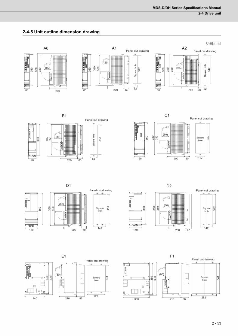
MDS-D/DH Series Specifications Manual
2-4 Drive unit
2 - 53
2-4-5 Unit outline dimension drawing
360
120
(80)
350
380
200 60
C1
342
112
360
150
D1
342
142
(80)
350
380
200 60
(80)
200 20
350
380
A2
52
342
Squa
re h
ole
Squa
re h
ole
Squa
re h
ole
Panel cut drawing
Panel cut drawingPanel cut drawing
Panel cut drawing
360
90
(80)
200 60
350
380
B1
82
342
360
150
D2
342
142
(80)
350
380
200 67
360
380
240
(80)
210 92
E1
341
222
360
380
300
(80)
210 92
F1
341
282
(80)
(80)
200
350
380
360
6036
060
360
60
A0
380
350
200 60
A1
342
52
Unit [mm]
Squarehole
Squarehole
Squarehole
Squarehole
Squarehole
Panel cut drawing Panel cut drawing
Panel cut drawingPanel cut drawing
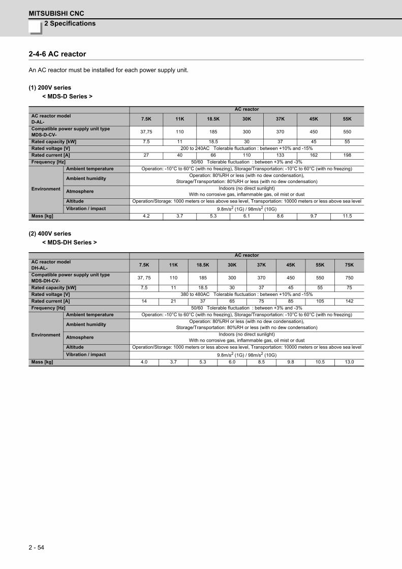
2 Specifications
MITSUBISHI CNC
2 - 54
2-4-6 AC reactor
An AC reactor must be installed for each power supply unit.
(1) 200V series
< MDS-D Series >
(2) 400V series
< MDS-DH Series >
AC reactor
AC reactor modelD-AL-
7.5K 11K 18.5K 30K 37K 45K 55K
Compatible power supply unit typeMDS-D-CV-
37,75 110 185 300 370 450 550
Rated capacity [kW] 7.5 11 18.5 30 37 45 55
Rated voltage [V] 200 to 240AC Tolerable fluctuation : between +10% and -15%
Rated current [A] 27 40 66 110 133 162 198
Frequency [Hz] 50/60 Tolerable fluctuation : between +3% and -3%
Environment
Ambient temperature Operation: -10°C to 60°C (with no freezing), Storage/Transportation: -10°C to 60°C (with no freezing)
Ambient humidityOperation: 80%RH or less (with no dew condensation),
Storage/Transportation: 80%RH or less (with no dew condensation)
AtmosphereIndoors (no direct sunlight)
With no corrosive gas, inflammable gas, oil mist or dust
Altitude Operation/Storage: 1000 meters or less above sea level, Transportation: 10000 meters or less above sea level
Vibration / impact 9.8m/s2 (1G) / 98m/s2 (10G)
Mass [kg] 4.2 3.7 5.3 6.1 8.6 9.7 11.5
AC reactor
AC reactor modelDH-AL-
7.5K 11K 18.5K 30K 37K 45K 55K 75K
Compatible power supply unit typeMDS-DH-CV-
37, 75 110 185 300 370 450 550 750
Rated capacity [kW] 7.5 11 18.5 30 37 45 55 75
Rated voltage [V] 380 to 480AC Tolerable fluctuation : between +10% and -15%
Rated current [A] 14 21 37 65 75 85 105 142
Frequency [Hz] 50/60 Tolerable fluctuation : between +3% and -3%
Environment
Ambient temperature Operation: -10°C to 60°C (with no freezing), Storage/Transportation: -10°C to 60°C (with no freezing)
Ambient humidityOperation: 80%RH or less (with no dew condensation),
Storage/Transportation: 80%RH or less (with no dew condensation)
AtmosphereIndoors (no direct sunlight)
With no corrosive gas, inflammable gas, oil mist or dust
Altitude Operation/Storage: 1000 meters or less above sea level, Transportation: 10000 meters or less above sea level
Vibration / impact 9.8m/s2 (1G) / 98m/s2 (10G)
Mass [kg] 4.0 3.7 5.3 6.0 8.5 9.8 10.5 13.0
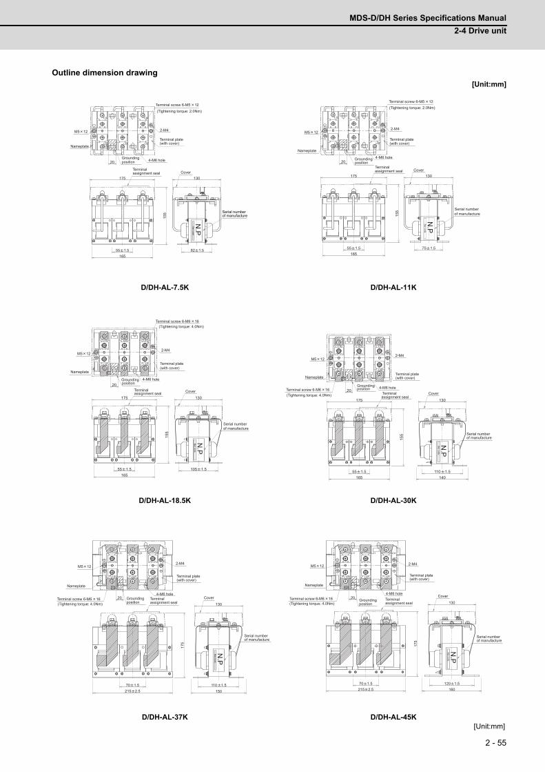
MDS-D/DH Series Specifications Manual
2-4 Drive unit
2 - 55
Outline dimension drawing[Unit:mm]
D/DH-AL-7.5K D/DH-AL-11K
D/DH-AL-18.5K D/DH-AL-30K
D/DH-AL-37K D/DH-AL-45K[Unit:mm]
N.P
55 1.5165
155
82 1.5
130175
20
L11 L21 L31
L12 L22 L32
FG2-M4M5 12
(Tightening torque: 2.0Nm)
Terminal screw 6-M5 12
(with cover)Nameplate
4-M6 hole
Terminal plate
Groundingposition
Terminalassignment seal Cover
Bar code
of manufactureSerial number
N.P
55 1.5165
155
75 1.5
130175
20
L11 L21 L31
L12 L22 L32
FG 2-M4M5 12
Terminal screw 6-M5 12
Terminal plate(with cover)
position
Nameplate
4-M6 holeGrounding
Terminalassignment seal Cover
Bar code
Serial numberof manufacture
(Tightening torque: 2.0Nm)
N.P
55 1.5165
155
105 1.5
175 130
20
L11 L21 L31
L12 L22 L32
FG 2-M4M5 12
4-M6 hole
Terminal screw 6-M6 16
(with cover)
position
Nameplate
Terminal plate
Grounding
assignment sealTerminal Cover
of manufacture
Bar code
Serial number
(Tightening torque: 4.0Nm)
N.P
55 1.5165
155
110 1.5140
175 130
20
L11 L21 L31
L12 L22 L32
FG 2-M4M5 12
4-M6 holeTerminal screw 6-M6 16
Nameplate
positionGrounding
(with cover)Terminal plate
Terminalassignment seal
Cover
Bar code
of manufactureSerial number
(Tightening torque: 4.0Nm)
N.P
70 1.5215 2.5
175
110 1.5150
130
20
L11 L21 L31
L12 L22 L32
FG 2-M4M5 12
4-M6 holeTerminal screw 6-M6 16
Nameplate
positionGrounding
(with cover)Terminal plate
Cover
Bar code
Terminalassignment seal
of manufactureSerial number
(Tightening torque: 4.0Nm)
N.P
70 1.5215 2.5
175
120 1.5160
13020
L11 L21 L31
L12 L22 L32
FG 2-M4M5 12
4-M6 holeTerminal screw 6-M6 16
Cover
Bar code
Nameplate(with cover)Terminal plate
positionGrounding Terminal
assignment seal
of manufactureSerial number
(Tightening torque: 4.0Nm)
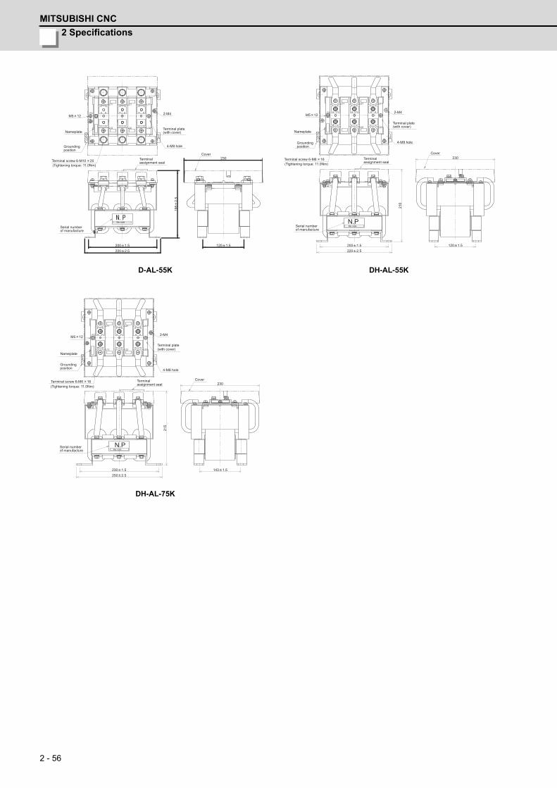
2 Specifications
MITSUBISHI CNC
2 - 56
D-AL-55K DH-AL-55K
DH-AL-75K
200 1.5220 2.5
195
2.5
120 1.5
230
L11 L21 L31
L12 L22 L32
FG 2-M4M5 12
Terminal screw 6-M10 20
4-M8 hole
Nameplate
positionGrounding
(with cover)Terminal plate
of manufactureSerial number
Terminalassignment seal
Cover
Bar code
(Tightening torque: 11.0Nm)
200 1.5220 2.5
120 1.5
230
L11 L21 L31
L22 L32
FG
210
N.P
2-M4M5 12
4-M8 hole
Terminal screw 6-M6 16
Nameplate
positionGrounding
(with cover)Terminal plate
Bar code
Cover
of manufactureSerial number
Terminalassignment seal(Tightening torque: 11.0Nm)
230 1.5250 2.5
143 1.5
L11 L21 L31
L12 L22 L32
FG
215
N.P
230
2-M4M5 12
4-M8 hole
Terminal screw 6-M6 16
Nameplate
Groundingposition
(with cover)Terminal plate
Cover
Bar code
Terminalassignment seal
of manufactureSerial number
(Tightening torque: 11.0Nm)
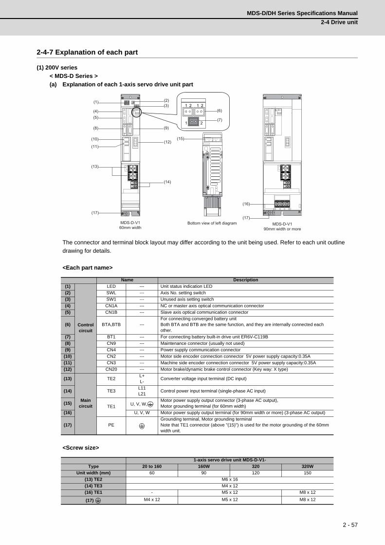
MDS-D/DH Series Specifications Manual
2-4 Drive unit
2 - 57
2-4-7 Explanation of each part
(1) 200V series
< MDS-D Series >
(a) Explanation of each 1-axis servo drive unit part
The connector and terminal block layout may differ according to the unit being used. Refer to each unit outline
drawing for details.
<Each part name>
<Screw size>
Name Description
(1)
Controlcircuit
LED --- Unit status indication LED
(2) SWL --- Axis No. setting switch
(3) SW1 --- Unused axis setting switch
(4) CN1A --- NC or master axis optical communication connector
(5) CN1B --- Slave axis optical communication connector
(6) BTA,BTB ---For connecting converged battery unitBoth BTA and BTB are the same function, and they are internally connected each other.
(7) BT1 --- For connecting battery built-in drive unit ER6V-C119B
(8) CN9 --- Maintenance connector (usually not used)
(9) CN4 --- Power supply communication connector
(10) CN2 --- Motor side encoder connection connector 5V power supply capacity:0.35A
(11) CN3 --- Machine side encoder connection connector 5V power supply capacity:0.35A
(12) CN20 --- Motor brake/dynamic brake control connector (Key way: X type)
(13)
Main circuit
TE2L+L-
Converter voltage input terminal (DC input)
(14) TE3L11L21
Control power input terminal (single-phase AC input)
(15)TE1 U, V, W,
Motor power supply output connector (3-phase AC output),Motor grounding terminal (for 60mm width)
(16) U, V, W Motor power supply output terminal (for 90mm width or more) (3-phase AC output)
(17) PEGrounding terminal, Motor grounding terminalNote that TE1 connector (above "(15)") is used for the motor grounding of the 60mm width unit.
1-axis servo drive unit MDS-D-V1-
Type 20 to 160 160W 320 320W
Unit width (mm) 60 90 120 150
(13) TE2 M6 x 16
(14) TE3 M4 x 12
(16) TE1 - M5 x 12 M8 x 12
(17) M4 x 12 M5 x 12 M8 x 12
MDS-D-V160mm width
Bottom view of left diagram MDS-D-V190mm width or more
(6)
(7)
(15)
(16)
(2)(3)
(9)
(12)
(14)
(1)
(4)(5)
(8)
(10)
(11)
(13)
(17)
1 2
1 2 1 2
(17)
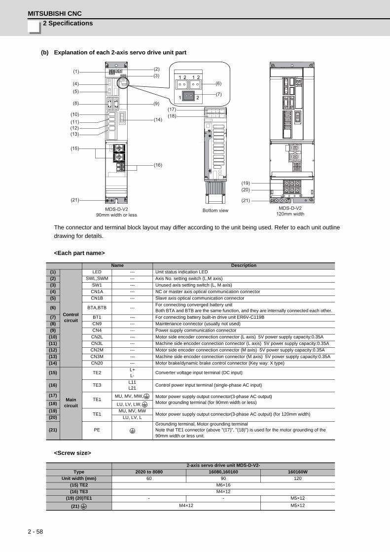
2 Specifications
MITSUBISHI CNC
2 - 58
(b) Explanation of each 2-axis servo drive unit part
The connector and terminal block layout may differ according to the unit being used. Refer to each unit outline
drawing for details.
<Each part name>
<Screw size>
Name Description
(1)
Control circuit
LED --- Unit status indication LED
(2) SWL,SWM --- Axis No. setting switch (L,M axis)
(3) SW1 --- Unused axis setting switch (L, M axis)
(4) CN1A --- NC or master axis optical communication connector
(5) CN1B --- Slave axis optical communication connector
(6) BTA,BTB ---For connecting converged battery unitBoth BTA and BTB are the same function, and they are internally connected each other.
(7) BT1 --- For connecting battery built-in drive unit ER6V-C119B
(8) CN9 --- Maintenance connector (usually not used)
(9) CN4 --- Power supply communication connector
(10) CN2L --- Motor side encoder connection connector (L axis) 5V power supply capacity:0.35A
(11) CN3L --- Machine side encoder connection connector (L axis) 5V power supply capacity:0.35A
(12) CN2M --- Motor side encoder connection connector (M axis) 5V power supply capacity:0.35A
(13) CN3M --- Machine side encoder connection connector (M axis) 5V power supply capacity:0.35A
(14) CN20 --- Motor brake/dynamic brake control connector (Key way: X type)
(15)
Main circuit
TE2L+L-
Converter voltage input terminal (DC input)
(16) TE3L11L21
Control power input terminal (single-phase AC input)
(17)TE1
MU, MV, MW, Motor power supply output connector(3-phase AC output)Motor grounding terminal (for 90mm width or less)(18) LU, LV, LW,
(19)TE1
MU, MV, MWMotor power supply output connector(3-phase AC output) (for 120mm width)
(20) LU, LV, L
(21) PEGrounding terminal, Motor grounding terminalNote that TE1 connector (above "(17)", "(18)") is used for the motor grounding of the 90mm width or less unit.
2-axis servo drive unit MDS-D-V2-
Type 2020 to 8080 16080,160160 160160W
Unit width (mm) 60 90 120
(15) TE2 M6×16
(16) TE3 M4×12
(19) (20)TE1 - - M5×12
(21) M4×12 M5×12
MDS-D-V290mm width or less
Bottom view MDS-D-V2120mm width
(6)
(7)
(15)
(16)
(2)(3)
(9)
(12)
(14)
(1)
(4)(5)
(8)
(10)(11)
(13)
(17)(18)
(21)
1 2
1 2 1 2
(21)
(19)(20)
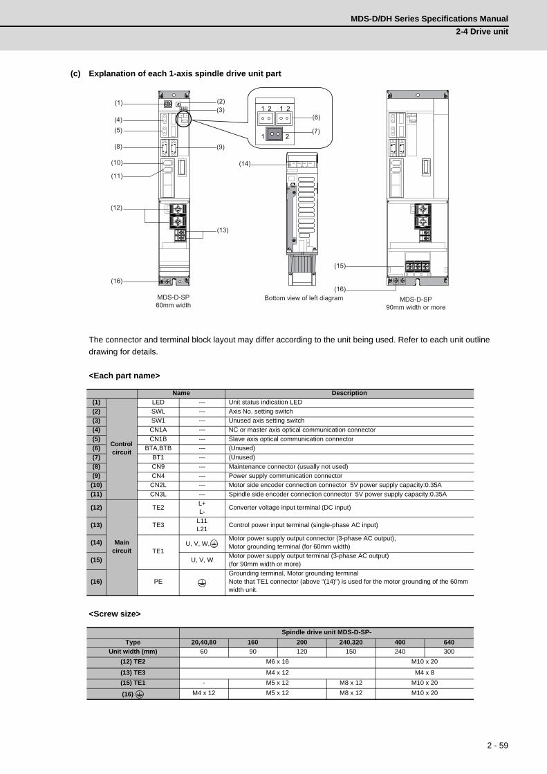
MDS-D/DH Series Specifications Manual
2-4 Drive unit
2 - 59
(c) Explanation of each 1-axis spindle drive unit part
The connector and terminal block layout may differ according to the unit being used. Refer to each unit outline
drawing for details.
<Each part name>
<Screw size>
Name Description
(1)
Control circuit
LED --- Unit status indication LED
(2) SWL --- Axis No. setting switch
(3) SW1 --- Unused axis setting switch
(4) CN1A --- NC or master axis optical communication connector
(5) CN1B --- Slave axis optical communication connector
(6) BTA,BTB --- (Unused)
(7) BT1 --- (Unused)
(8) CN9 --- Maintenance connector (usually not used)
(9) CN4 --- Power supply communication connector
(10) CN2L --- Motor side encoder connection connector 5V power supply capacity:0.35A
(11) CN3L --- Spindle side encoder connection connector 5V power supply capacity:0.35A
(12)
Main circuit
TE2L+L-
Converter voltage input terminal (DC input)
(13) TE3L11L21
Control power input terminal (single-phase AC input)
(14)TE1
U, V, W,Motor power supply output connector (3-phase AC output),Motor grounding terminal (for 60mm width)
(15) U, V, WMotor power supply output terminal (3-phase AC output)(for 90mm width or more)
(16) PEGrounding terminal, Motor grounding terminalNote that TE1 connector (above "(14)") is used for the motor grounding of the 60mm width unit.
Spindle drive unit MDS-D-SP-
Type 20,40,80 160 200 240,320 400 640
Unit width (mm) 60 90 120 150 240 300
(12) TE2 M6 x 16 M10 x 20
(13) TE3 M4 x 12 M4 x 8
(15) TE1 - M5 x 12 M8 x 12 M10 x 20
(16) M4 x 12 M5 x 12 M8 x 12 M10 x 20
MDS-D-SP60mm width
Bottom view of left diagram MDS-D-SP90mm width or more
(6)
(7)
(15)
(16)
(2)(3)
(9)
(12)
(14)
(1)
(4)(5)
(8)
(10)
(11)
(13)
1 2
1 2 1 2
(16)
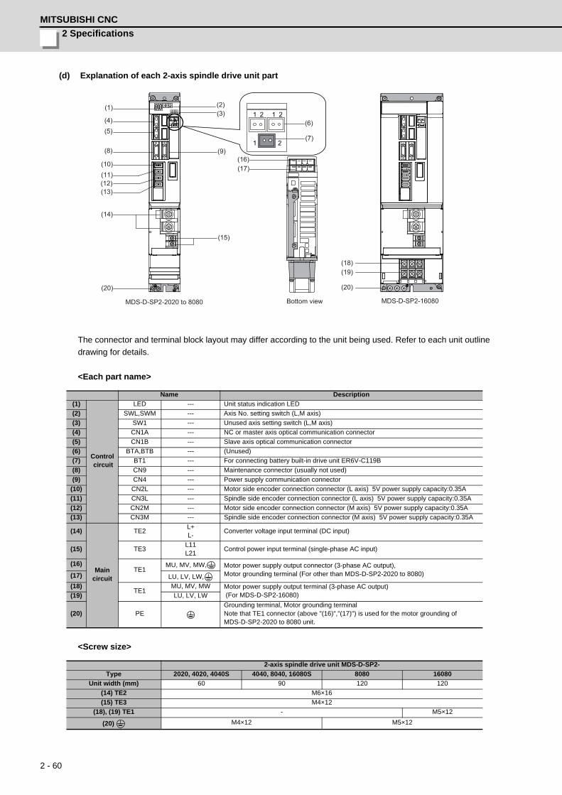
2 Specifications
MITSUBISHI CNC
2 - 60
(d) Explanation of each 2-axis spindle drive unit part
The connector and terminal block layout may differ according to the unit being used. Refer to each unit outline
drawing for details.
<Each part name>
<Screw size>
Name Description
(1)
Control circuit
LED --- Unit status indication LED
(2) SWL,SWM --- Axis No. setting switch (L,M axis)
(3) SW1 --- Unused axis setting switch (L,M axis)
(4) CN1A --- NC or master axis optical communication connector
(5) CN1B --- Slave axis optical communication connector
(6) BTA,BTB --- (Unused)
(7) BT1 --- For connecting battery built-in drive unit ER6V-C119B
(8) CN9 --- Maintenance connector (usually not used)
(9) CN4 --- Power supply communication connector
(10) CN2L --- Motor side encoder connection connector (L axis) 5V power supply capacity:0.35A
(11) CN3L --- Spindle side encoder connection connector (L axis) 5V power supply capacity:0.35A
(12) CN2M --- Motor side encoder connection connector (M axis) 5V power supply capacity:0.35A
(13) CN3M --- Spindle side encoder connection connector (M axis) 5V power supply capacity:0.35A
(14)
Main circuit
TE2L+L-
Converter voltage input terminal (DC input)
(15) TE3L11L21
Control power input terminal (single-phase AC input)
(16)TE1
MU, MV, MW, Motor power supply output connector (3-phase AC output),Motor grounding terminal (For other than MDS-D-SP2-2020 to 8080)(17) LU, LV, LW,
(18)TE1
MU, MV, MW Motor power supply output terminal (3-phase AC output) (For MDS-D-SP2-16080)(19) LU, LV, LW
(20) PEGrounding terminal, Motor grounding terminalNote that TE1 connector (above "(16)","(17)") is used for the motor grounding of MDS-D-SP2-2020 to 8080 unit.
2-axis spindle drive unit MDS-D-SP2-
Type 2020, 4020, 4040S 4040, 8040, 16080S 8080 16080
Unit width (mm) 60 90 120 120
(14) TE2 M6×16
(15) TE3 M4×12
(18), (19) TE1 - M5×12
(20) M4×12 M5×12
MDS-D-SP2-16080
(6)
(7)
(14)
(15)
(2)(3)
(9)
(12)
(1)
(4)(5)
(8)
(10)(11)
(13)
(16)(17)
(20)
1 2
1 2 1 2
(20)
(18)(19)
MDS-D-SP2-2020 to 8080
Bottom view
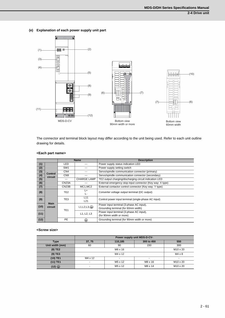
MDS-D/DH Series Specifications Manual
2-4 Drive unit
2 - 61
(e) Explanation of each power supply unit part
The connector and terminal block layout may differ according to the unit being used. Refer to each unit outline
drawing for details.
<Each part name>
<Screw size>
Name Description
(1)
Control circuit
LED --- Power supply status indication LED
(2) SW1 --- Power supply setting switch
(3) CN4 --- Servo/spindle communication connector (primary)
(4) CN9 --- Servo/spindle communication connector (secondary)
(5) --- CHARGE LAMP TE2 output charging/discharging circuit indication LED
(6) CN23A --- External emergency stop input connector (Key way: X type)
(7) CN23B MC1,MC2 External contactor control connector (Key way: Y type)
(8)
Main circuit
TE2L+L-
Converter voltage output terminal (DC output)
(9) TE3L11L21
Control power input terminal (single-phase AC input)
(10)TE1
L1,L2,L3,Power input terminal (3-phase AC input),Grounding terminal (for 60mm width)
(11) L1, L2, L3Power input terminal (3-phase AC input),(for 90mm width or more)
(12) PE Grounding terminal (for 90mm width or more)
Power supply unit MDS-D-CV-
Type 37, 75 110,185 300 to 450 550
Unit width (mm) 60 90 150 300
(8) TE2 M6 x 16 M10 x 20
(9) TE3 M4 x 12 M4 x 8
(10) TE1 M4 x 12 - - -
(11) TE1 - M5 x 12 M8 x 16 M10 x 20
(12) - M5 x 12 M8 x 14 M10 x 20
MDS-D-CV Bottom view90mm width or more
Bottom view60mm width
(6)(7)
(2)
(3)
(9)
(12)
(1)
(4)
(5)
(8)
(10)
(11)
(7)(6)
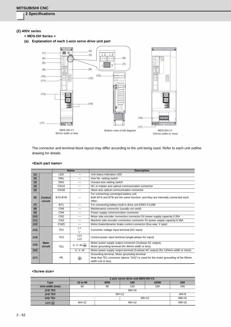
2 Specifications
MITSUBISHI CNC
2 - 62
(2) 400V series
< MDS-DH Series >
(a) Explanation of each 1-axis servo drive unit part
The connector and terminal block layout may differ according to the unit being used. Refer to each unit outline
drawing for details.
<Each part name>
<Screw size>
Name Description
(1)
Controlcircuit
LED --- Unit status indication LED
(2) SWL --- Axis No. setting switch
(3) SW1 --- Unused axis setting switch
(4) CN1A --- NC or master axis optical communication connector
(5) CN1B --- Slave axis optical communication connector
(6) BTA,BTB ---For connecting converged battery unitBoth BTA and BTB are the same function, and they are internally connected each other.
(7) BT1 --- For connecting battery built-in drive unit ER6V-C119B
(8) CN9 --- Maintenance connector (usually not used)
(9) CN4 --- Power supply communication connector
(10) CN2 --- Motor side encoder connection connector 5V power supply capacity:0.35A
(11) CN3 --- Machine side encoder connection connector 5V power supply capacity:0.35A
(12) CN20 --- Motor brake/dynamic brake control connector (Key way: X type)
(13)
Main circuit
TE2L+L-
Converter voltage input terminal (DC input)
(14) TE3L11L21
Control power input terminal (single-phase AC input)
(15)TE1 U, V, W,
Motor power supply output connector (3-phase AC output),Motor grounding terminal (for 90mm width or less)
(16) U, V, W Motor power supply output terminal (3-phase AC output) (for 120mm width or more)
(17) PEGrounding terminal, Motor grounding terminalNote that TE1 connector (above "(15)") is used for the motor grounding of the 90mm width unit or less.
1-axis servo drive unit MDS-DH-V1-
Type 10 to 80 80W 160 160W 200
Unit width (mm) 60 90 120 150 240
(13) TE2 M6×16
(14) TE3 M4×12 M4×8
(16) TE1 - M5×12 M8×15
(17) M4×12 M5×12 M8×16
MDS-DH-V190mm width or less
Bottom view of left diagram MDS-DH-V1120mm width or more
(2)(3)
(4)
(5)
(1)
(9)
(12)
(14)
(17)
(15)
(8)
(10)
(11)
(13)
(6)
(7)
(16)
(17)
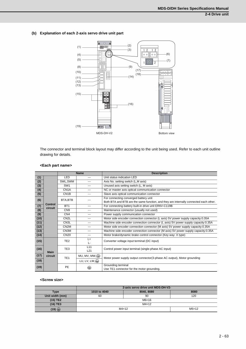
MDS-D/DH Series Specifications Manual
2-4 Drive unit
2 - 63
(b) Explanation of each 2-axis servo drive unit part
The connector and terminal block layout may differ according to the unit being used. Refer to each unit outline
drawing for details.
<Each part name>
<Screw size>
Name Description
(1)
Control circuit
LED --- Unit status indication LED
(2) SWL,SWM --- Axis No. setting switch (L,M axis)
(3) SW1 --- Unused axis setting switch (L, M axis)
(4) CN1A --- NC or master axis optical communication connector
(5) CN1B --- Slave axis optical communication connector
(6) BTA,BTB ---For connecting converged battery unitBoth BTA and BTB are the same function, and they are internally connected each other.
(7) BT1 --- For connecting battery built-in drive unit ER6V-C119B
(8) CN9 --- Maintenance connector (usually not used)
(9) CN4 --- Power supply communication connector
(10) CN2L --- Motor side encoder connection connector (L axis) 5V power supply capacity:0.35A
(11) CN3L --- Machine side encoder connection connector (L axis) 5V power supply capacity:0.35A
(12) CN2M --- Motor side encoder connection connector (M axis) 5V power supply capacity:0.35A
(13) CN3M --- Machine side encoder connection connector (M axis) 5V power supply capacity:0.35A
(14) CN20 --- Motor brake/dynamic brake control connector (Key way: X type)
(15)
Main circuit
TE2L+L-
Converter voltage input terminal (DC input)
(16) TE3L11L21
Control power input terminal (single-phase AC input)
(17)TE1
MU, MV, MW,Motor power supply output connector(3-phase AC output), Motor grounding
(18) LU, LV, LW,
(19) PEGrounding terminalUse TE1 connector for the motor grounding.
2-axis servo drive unit MDS-DH-V2-
Type 1010 to 4040 8040, 8080 8080
Unit width (mm) 60 90 120
(15) TE2 M6×16
(16) TE3 M4×12
(19) M4×12 M5×12
MDS-DH-V2 Bottom view
(2)(3)
(4)
(5)
(1)
(9)
(12)
(14)
(17)
(15)
(8)
(10)
(11)
(13)
(6)
(7)
(16)
(18)
(19)
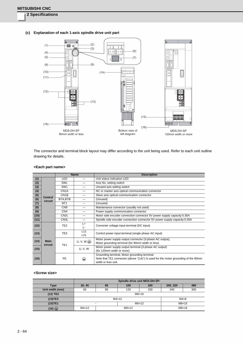
2 Specifications
MITSUBISHI CNC
2 - 64
(c) Explanation of each 1-axis spindle drive unit part
The connector and terminal block layout may differ according to the unit being used. Refer to each unit outline
drawing for details.
<Each part name>
<Screw size>
Name Description
(1)
Control circuit
LED --- Unit status indication LED
(2) SWL --- Axis No. setting switch
(3) SW1 --- Unused axis setting switch
(4) CN1A --- NC or master axis optical communication connector
(5) CN1B --- Slave axis optical communication connector
(6) BTA,BTB --- (Unused)
(7) BT1 --- (Unused)
(8) CN9 --- Maintenance connector (usually not used)
(9) CN4 --- Power supply communication connector
(10) CN2L --- Motor side encoder connection connector 5V power supply capacity:0.35A
(11) CN3L --- Spindle side encoder connection connector 5V power supply capacity:0.35A
(12)
Main circuit
TE2L+L-
Converter voltage input terminal (DC input)
(13) TE3L11L21
Control power input terminal (single-phase AC input)
(14)TE1
U, V, W,Motor power supply output connector (3-phase AC output),Motor grounding terminal (for 90mm width or less)
(15) U, V, WMotor power supply output terminal (3-phase AC output)(for 120mm width or more)
(16) PEGrounding terminal, Motor grounding terminalNote that TE1 connector (above "(14)") is used for the motor grounding of the 90mm width or less unit.
Spindle drive unit MDS-DH-SP-
Type 20, 40 80 100 160 200, 320 480
Unit width (mm) 60 90 120 150 240 300
(12) TE2 M6×16
(13)TE3 M4×12 M4×8
(15)TE1 - M5×12 M8×15
(16) M4×12 M5×12 M8×16
MDS-DH-SP90mm width or less
Bottom view of left diagram
MDS-DH-SP120mm width or more
(2)(3)
(4)(5)
(1)
(9)
(12)
(14)
(15)
(8)
(10)
(11)
(13)
(6)
(7)
(16)(16)

MDS-D/DH Series Specifications Manual
2-4 Drive unit
2 - 65
(d) Explanation of each power supply unit part
The connector and terminal block layout may differ according to the unit being used. Refer to each unit outline
drawing for details.
<Each part name>
<Screw size>
Name Description
(1)
Control circuit
LED --- Power supply status indication LED
(2) SW1 --- Power supply setting switch
(3) CN4 --- Servo/spindle communication connector (primary)
(4) CN9 --- Servo/spindle communication connector (secondary)
(5) ---CHARGE
LAMPTE2 output charging/discharging circuit indication LED
(6) CN23A --- External emergency stop input connector (Key way: X type)
(7) CN23B MC1,MC2 External contactor control connector (Key way: Y type)
(8)
Main circuit
TE2L+L-
Converter voltage output terminal (DC output)
(9) TE3L11L21
Control power input terminal (single-phase AC input)
(10) TE1 L1, L2, L3 Power input terminal (3-phase AC input)
(11) PE Grounding terminal
Power supply unit MDS-DH-CV-
Type 37 to 185 300 to 450 550, 750
Unit width (mm) 90 150 300
(8) TE2 M6×16 M6×16
(9) TE3 M4×12 M4×8
(10) TE1 M5×12 M8×16 M8×15
(11) M5×12 M8×14 M8×16
MDS-DH-CV
Bottom view
(2)
(3)
(4)
(5)
(1)
(9)
(8)
(10)
(11)
(6) (7)

2 Specifications
MITSUBISHI CNC
2 - 66

3 - 1
3
Function Specifications
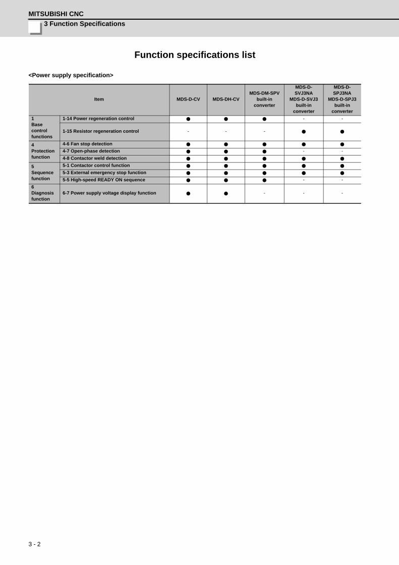
3 Function Specifications
MITSUBISHI CNC
3 - 2
Function specifications list
<Power supply specification>
Item MDS-D-CV MDS-DH-CVMDS-DM-SPV
built-in converter
MDS-D-SVJ3NA
MDS-D-SVJ3built-in
converter
MDS-D-SPJ3NA
MDS-D-SPJ3built-in
converter
1 Base controlfunctions
1-14 Power regeneration control - -
1-15 Resistor regeneration control - - -
4 Protection function
4-6 Fan stop detection
4-7 Open-phase detection - -
4-8 Contactor weld detection
5 Sequence function
5-1 Contactor control function
5-3 External emergency stop function
5-5 High-speed READY ON sequence - -
6 Diagnosis function
6-7 Power supply voltage display function - - -
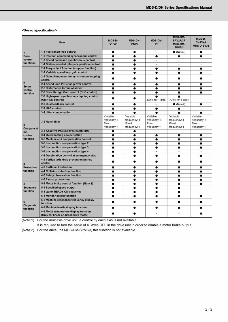
MDS-D/DH Series Specifications Manual
3 - 3
<Servo specification>
(Note 1) For the multiaxis drive unit, a control by each axis is not available.
It is required to turn the servo of all axes OFF in the drive unit in order to enable a motor brake output.
(Note 2) For the drive unit MDS-DM-SPV2/3, this function is not available.
ItemMDS-D-V1/V2
MDS-DH-V1/V2
MDS-DM-V3
MDS-DM-SPV2F/3FMDS-DM-SPV2/3
MDS-D-SVJ3NA
MDS-D-SVJ3
1 Base controlfunctions
1-1 Full closed loop control - (Note2)
1-2 Position command synchronous control
1-3 Speed command synchronous control - - -
1-4 Distance-coded reference position control - - -
2 Servo control function
2-1 Torque limit function (stopper function)
2-2 Variable speed loop gain control
2-3 Gain changeover for synchronous tapping control
2-4 Speed loop PID changeover control
2-5 Disturbance torque observer
2-6 Smooth High Gain control (SHG control)
2-7 High-speed synchronous tapping control (OMR-DD control)
(Only for 1-axis)
(Only for 1-axis)
-
2-8 Dual feedback control - (Note2)
2-9 HAS control -
3 Compensation controlfunction
3-1 Jitter compensation
3-2 Notch filter
Variable frequency: 4Fixed frequency: 1
Variable frequency: 4Fixed frequency: 1
Variable frequency: 4Fixed frequency: 1
Variable frequency: 4Fixed frequency: 1
Variable frequency: 4Fixed frequency: 1
3-3 Adaptive tracking-type notch filter - - -
3-4 Overshooting compensation
3-5 Machine end compensation control
3-6 Lost motion compensation type 2
3-7 Lost motion compensation type 3
3-8 Lost motion compensation type 4 - - -
4 Protection function
4-1 Deceleration control at emergency stop
4-2 Vertical axis drop prevention/pull-up control
4-3 Earth fault detection
4-4 Collision detection function
4-5 Safety observation function
4-6 Fan stop detection
5 Sequence function
5-2 Motor brake control function (Note 1)
5-4 Specified speed output -
5-5 Quick READY ON sequence -
6 Diagnosis function
6-1 Monitor output function
6-2 Machine resonance frequency display function
6-3 Machine inertia display function
6-4 Motor temperature display function(Only for linear or direct-drive motor) - -
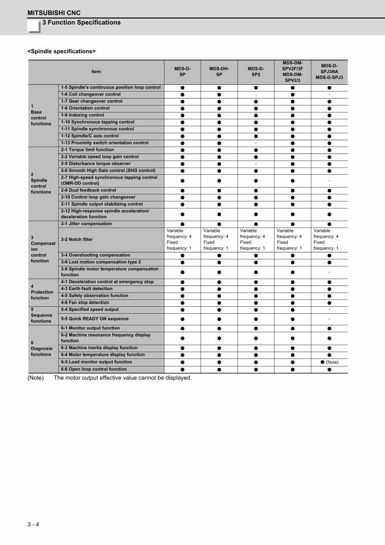
3 Function Specifications
MITSUBISHI CNC
3 - 4
<Spindle specifications>
(Note) The motor output effective value cannot be displayed.
ItemMDS-D-
SPMDS-DH-
SPMDS-D-
SP2
MDS-DM-SPV2F/3FMDS-DM-SPV2/3
MDS-D-SPJ3NA
MDS-D-SPJ3
1 Base controlfunctions
1-5 Spindle's continuous position loop control
1-6 Coil changeover control - -
1-7 Gear changeover control
1-8 Orientation control
1-9 Indexing control
1-10 Synchronous tapping control
1-11 Spindle synchronous control
1-12 Spindle/C axis control
1-13 Proximity switch orientation control -
2 Spindle control functions
2-1 Torque limit function
2-2 Variable speed loop gain control
2-5 Disturbance torque observer -
2-6 Smooth High Gain control (SHG control)
2-7 High-speed synchronous tapping control (OMR-DD control) -
2-8 Dual feedback control
2-10 Control loop gain changeover
2-11 Spindle output stabilizing control
2-12 High-response spindle acceleration/deceleration function
3 Compensation controlfunction
3-1 Jitter compensation
3-2 Notch filter
Variable frequency: 4Fixed frequency: 1
Variable frequency: 4Fixed frequency: 1
Variable frequency: 4Fixed frequency: 1
Variable frequency: 4Fixed frequency: 1
Variable frequency: 4Fixed frequency: 1
3-4 Overshooting compensation
3-6 Lost motion compensation type 2
3-9 Spindle motor temperature compensation function -
4 Protection function
4-1 Deceleration control at emergency stop
4-3 Earth fault detection
4-5 Safety observation function
4-6 Fan stop detection
5 Sequence functions
5-4 Specified speed output -
5-5 Quick READY ON sequence -
6 Diagnosis functions
6-1 Monitor output function
6-2 Machine resonance frequency display function
6-3 Machine inertia display function
6-4 Motor temperature display function
6-5 Load monitor output function (Note)
6-6 Open loop control function

MDS-D/DH Series Specifications Manual
3-1 Base control functions
3 - 5
3-1 Base control functions3-1-1 Full closed loop control
The servo control is all closed loop control using the encoder's feedback. "Full closed loop control" is the system that
directly detects the machine position using a linear scale, whereas the general "semi-closed loop" is the one that detects
the motor position.
In a machine that drives a table with a ball screw, the following factors exist between the motor and table end:
(1) Coupling or ball screw table bracket's backlash
(2) Ball screw pitch error
These can adversely affect the accuracy. If the table position of the machine side is directly detected with a linear scale,
high-accuracy position control which is not affected by backlash or pitch error is possible.
+ + +- - -
ENC
IG VGN PGN NC
+ + +- - -
IG VGN PGN NC
Positioncommand
Full closed loop control (servo)
Position command
Current command
Voltagecommand
Speed FBCurrent FB
Position FB
Servomotor
Table
Linear scale
The ball screw side encoder is also applied.
Positioncommand
Full closed loop control (spindle)
Position command
Current command
Voltagecommand
Speed FBCurrent FB
Position FB V-belt
SpindleSpindle encoder
Motor encoder
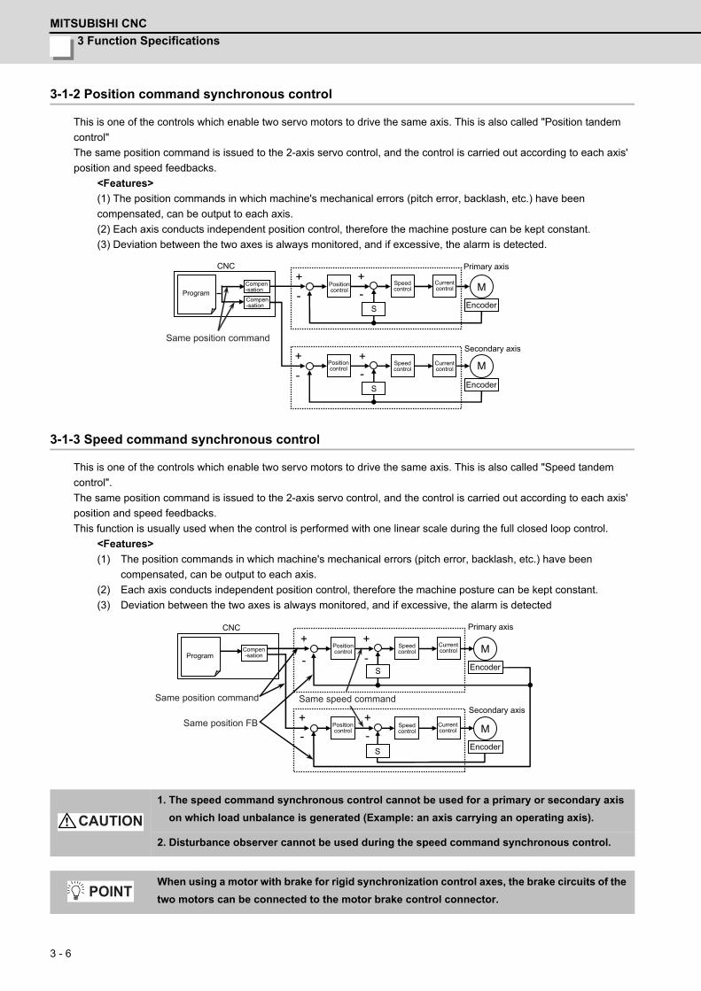
3 Function Specifications
MITSUBISHI CNC
3 - 6
3-1-2 Position command synchronous control
This is one of the controls which enable two servo motors to drive the same axis. This is also called "Position tandem
control"
The same position command is issued to the 2-axis servo control, and the control is carried out according to each axis'
position and speed feedbacks.
<Features>
(1) The position commands in which machine's mechanical errors (pitch error, backlash, etc.) have been
compensated, can be output to each axis.
(2) Each axis conducts independent position control, therefore the machine posture can be kept constant.
(3) Deviation between the two axes is always monitored, and if excessive, the alarm is detected.
3-1-3 Speed command synchronous control
This is one of the controls which enable two servo motors to drive the same axis. This is also called "Speed tandem
control".
The same position command is issued to the 2-axis servo control, and the control is carried out according to each axis'
position and speed feedbacks.
This function is usually used when the control is performed with one linear scale during the full closed loop control.
<Features>
(1) The position commands in which machine's mechanical errors (pitch error, backlash, etc.) have been
compensated, can be output to each axis.
(2) Each axis conducts independent position control, therefore the machine posture can be kept constant.
(3) Deviation between the two axes is always monitored, and if excessive, the alarm is detected
1. The speed command synchronous control cannot be used for a primary or secondary axis
on which load unbalance is generated (Example: an axis carrying an operating axis).
2. Disturbance observer cannot be used during the speed command synchronous control.
When using a motor with brake for rigid synchronization control axes, the brake circuits of the
two motors can be connected to the motor brake control connector.
+
+ +
+-
- -
- M
CNC
S
M
S
Same position command
ProgramCompen-sation
Compen-sation
Positioncontrol
Positioncontrol
Speedcontrol
Speedcontrol
Currentcontrol
Currentcontrol
Encoder
Encoder
Primary axis
Secondary axis
+
+
+
+
-
-
-
-
M
S
M
S
CNC
Same position command
ProgramCompen-sation
Positioncontrol
Positioncontrol
Speedcontrol
Speedcontrol
Currentcontrol
Currentcontrol
Encoder
Encoder
Primary axis
Secondary axisSame position FB
Same speed command
CAUTION
POINT
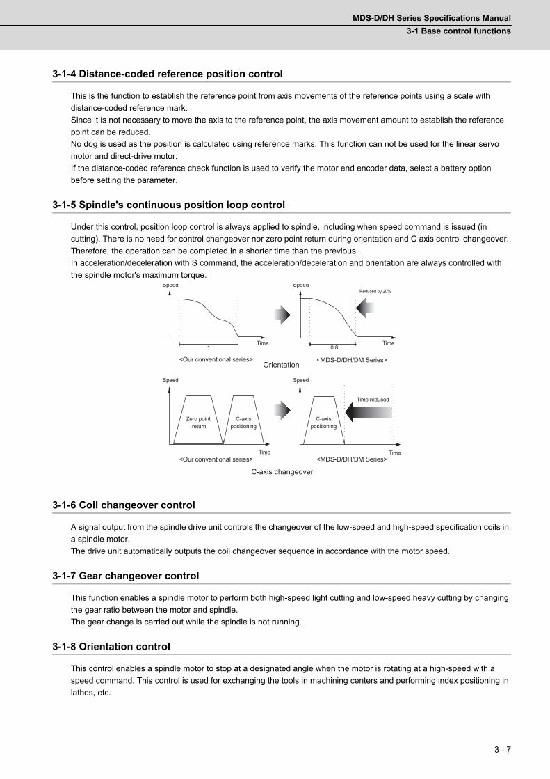
MDS-D/DH Series Specifications Manual
3-1 Base control functions
3 - 7
3-1-4 Distance-coded reference position control
This is the function to establish the reference point from axis movements of the reference points using a scale with
distance-coded reference mark.
Since it is not necessary to move the axis to the reference point, the axis movement amount to establish the reference
point can be reduced.
No dog is used as the position is calculated using reference marks. This function can not be used for the linear servo
motor and direct-drive motor.
If the distance-coded reference check function is used to verify the motor end encoder data, select a battery option
before setting the parameter.
3-1-5 Spindle's continuous position loop control
Under this control, position loop control is always applied to spindle, including when speed command is issued (in
cutting). There is no need for control changeover nor zero point return during orientation and C axis control changeover.
Therefore, the operation can be completed in a shorter time than the previous.
In acceleration/deceleration with S command, the acceleration/deceleration and orientation are always controlled with
the spindle motor's maximum torque.
3-1-6 Coil changeover control
A signal output from the spindle drive unit controls the changeover of the low-speed and high-speed specification coils in
a spindle motor.
The drive unit automatically outputs the coil changeover sequence in accordance with the motor speed.
3-1-7 Gear changeover control
This function enables a spindle motor to perform both high-speed light cutting and low-speed heavy cutting by changing
the gear ratio between the motor and spindle.
The gear change is carried out while the spindle is not running.
3-1-8 Orientation control
This control enables a spindle motor to stop at a designated angle when the motor is rotating at a high-speed with a
speed command. This control is used for exchanging the tools in machining centers and performing index positioning in
lathes, etc.
1 0.8
Zero point return
C-axispositioning
<Our conventional series>
<MDS-D/DH/DM Series>
C-axispositioning
Time reduced
TimeTime
TimeTime
SpeedSpeed
SpeedSpeedReduced by 20%
Orientation
C-axis changeover
<Our conventional series>
<MDS-D/DH/DM Series>
3 Function Specifications
MITSUBISHI CNC
3 - 8
3-1-9 Indexing control
This control enables positioning of a spindle motor at an arbitrary angle (in increments of 0.01 degrees) from the
orientation stop position. This control is used for positioning in lathes for hole drilling, etc.
3-1-10 Synchronous tapping control
Under synchronous tapping control, spindle control is completely synchronized with Z axis servo control, and Z axis is
accurately fed by one screw pitch in accordance with one tap revolution. The tap is completely fixed to the spindle head.
As a result, feed pitch error is less likely to occur, which allows high-speed, high-accuracy and high-durable tapping.
3-1-11 Spindle synchronous control
This control enables two spindles to run at the same speed. A spindle being driven with a speed command is
synchronized with another spindle at a constant rate or acceleration/deceleration rate.
This control is applied such as when a workpiece is transferred between two rotating chucks in lathe or a workpiece is
held with two chucks.
3-1-12 Spindle/C axis control
An axis rotating about Z axis is called C axis, whose rotation direction is normally the same as of spindle. This function
enables high-accuracy spindle control including interpolation control, like servo axis, when a high-resolution position
encoder is attached to the spindle motor.
3-1-13 Proximity switch orientation control
Orientation control is carried out based on the leading edge position of the proximity switch output signal (ON/OFF).
3-1-14 Power regeneration control
This control enables the regeneration energy generated when the motor decelerates to return to the power supply.
This is an energy saving method because regeneration energy is hardly converted to heat.
3-1-15 Resistor regeneration control
This control enables the regeneration energy generated when the motor decelerates to convert to heat with regenerative
resistance.
The drive system can be downsized because the regeneration capacity is also small in the motor of relatively small
capacity.
Select a suitable regenerative resistance according to the load inertia, motor operation speed, etc.
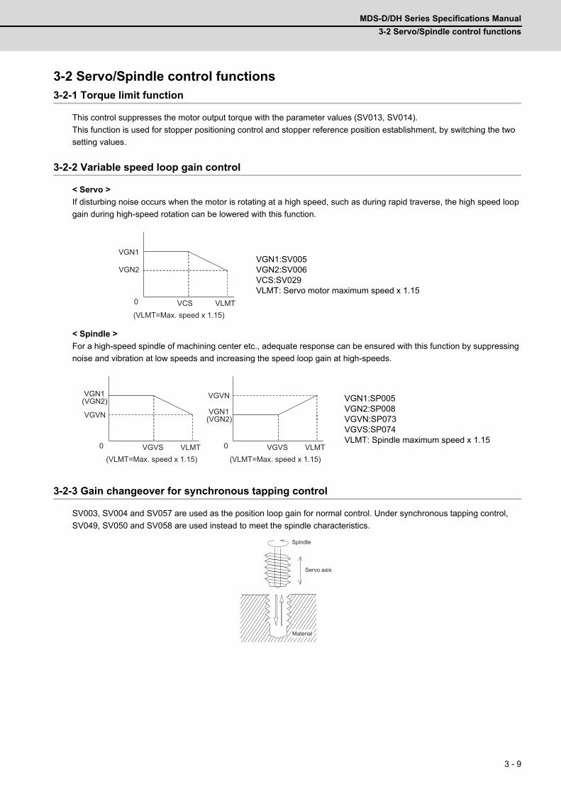
MDS-D/DH Series Specifications Manual
3-2 Servo/Spindle control functions
3 - 9
3-2 Servo/Spindle control functions3-2-1 Torque limit function
This control suppresses the motor output torque with the parameter values (SV013, SV014).
This function is used for stopper positioning control and stopper reference position establishment, by switching the two
setting values.
3-2-2 Variable speed loop gain control
< Servo >
If disturbing noise occurs when the motor is rotating at a high speed, such as during rapid traverse, the high speed loop
gain during high-speed rotation can be lowered with this function.
< Spindle >
For a high-speed spindle of machining center etc., adequate response can be ensured with this function by suppressing
noise and vibration at low speeds and increasing the speed loop gain at high-speeds.
3-2-3 Gain changeover for synchronous tapping control
SV003, SV004 and SV057 are used as the position loop gain for normal control. Under synchronous tapping control,
SV049, SV050 and SV058 are used instead to meet the spindle characteristics.
VGN1:SV005VGN2:SV006VCS:SV029VLMT: Servo motor maximum speed x 1.15
VGN1:SP005VGN2:SP008VGVN:SP073VGVS:SP074VLMT: Spindle maximum speed x 1.15
0 VLMTVCS
VGN2
VGN1
(VLMT=Max. speed x 1.15)
0 VGVS VLMT
VGVN
VGN1(VGN2)
0 VGVS VLMT
VGVN
VGN1(VGN2)
(VLMT=Max. speed x 1.15)(VLMT=Max. speed x 1.15)
Spindle
Servo axis
Material
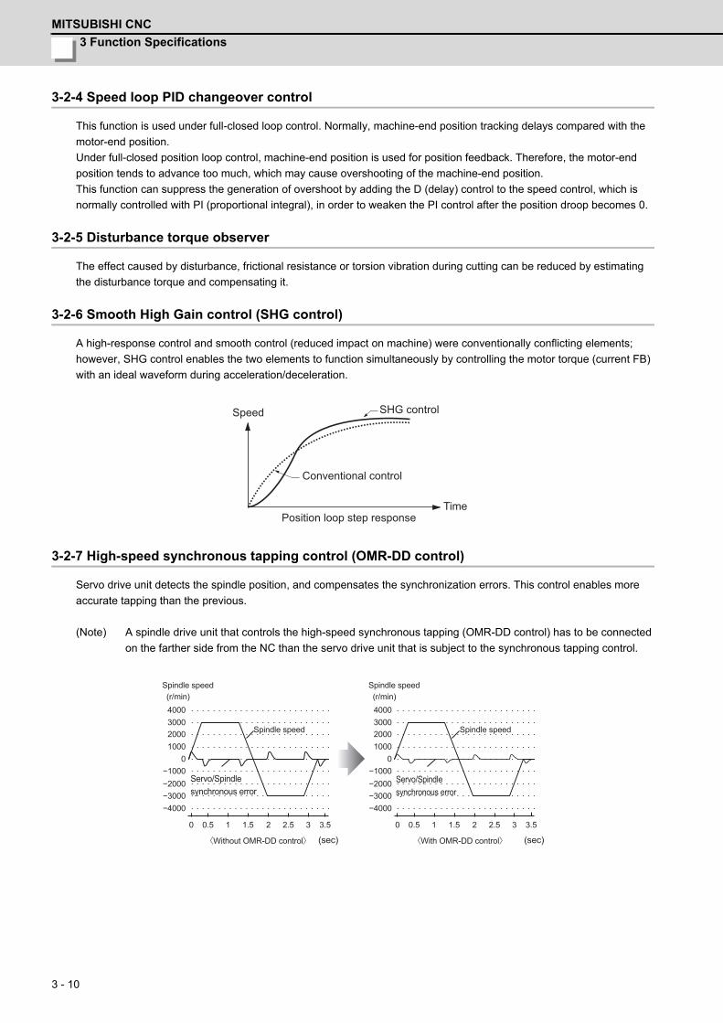
3 Function Specifications
MITSUBISHI CNC
3 - 10
3-2-4 Speed loop PID changeover control
This function is used under full-closed loop control. Normally, machine-end position tracking delays compared with the
motor-end position.
Under full-closed position loop control, machine-end position is used for position feedback. Therefore, the motor-end
position tends to advance too much, which may cause overshooting of the machine-end position.
This function can suppress the generation of overshoot by adding the D (delay) control to the speed control, which is
normally controlled with PI (proportional integral), in order to weaken the PI control after the position droop becomes 0.
3-2-5 Disturbance torque observer
The effect caused by disturbance, frictional resistance or torsion vibration during cutting can be reduced by estimating
the disturbance torque and compensating it.
3-2-6 Smooth High Gain control (SHG control)
A high-response control and smooth control (reduced impact on machine) were conventionally conflicting elements;
however, SHG control enables the two elements to function simultaneously by controlling the motor torque (current FB)
with an ideal waveform during acceleration/deceleration.
3-2-7 High-speed synchronous tapping control (OMR-DD control)
Servo drive unit detects the spindle position, and compensates the synchronization errors. This control enables more
accurate tapping than the previous.
(Note) A spindle drive unit that controls the high-speed synchronous tapping (OMR-DD control) has to be connected
on the farther side from the NC than the servo drive unit that is subject to the synchronous tapping control.
SHG controlSpeed
Conventional control
Position loop step responseTime
−4000−3000
0 0.5 1 1.5 2 2.5 3 3.5
−2000−1000
1000200030004000
0
−4000−3000
0 0.5 1 1.5 2 2.5 3 3.5
−2000−1000
1000200030004000
0
(r/min) (r/min)
Spindle speedSpindle speed
Spindle speed Spindle speed
Servo/Spindlesynchronous error
(sec) (sec)
Servo/Spindlesynchronous error
〈Without OMR-DD control〉 〈With OMR-DD control〉
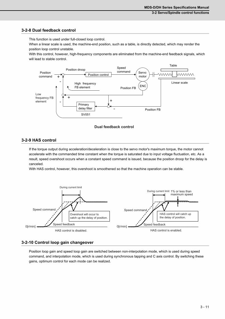
MDS-D/DH Series Specifications Manual
3-2 Servo/Spindle control functions
3 - 11
3-2-8 Dual feedback control
This function is used under full-closed loop control.
When a linear scale is used, the machine-end position, such as a table, is directly detected, which may render the
position loop control unstable.
With this control, however, high-frequency components are eliminated from the machine-end feedback signals, which
will lead to stable control.
3-2-9 HAS control
If the torque output during acceleration/deceleration is close to the servo motor's maximum torque, the motor cannot
accelerate with the commanded time constant when the torque is saturated due to input voltage fluctuation, etc. As a
result, speed overshoot occurs when a constant speed command is issued, because the position droop for the delay is
canceled.
With HAS control, however, this overshoot is smoothened so that the machine operation can be stable.
3-2-10 Control loop gain changeover
Position loop gain and speed loop gain are switched between non-interpolation mode, which is used during speed
command, and interpolation mode, which is used during synchronous tapping and C axis control. By switching these
gains, optimum control for each mode can be realized.
ENC
SV051
+
++
-
--
Position control
Primary delay filter
High frequency FB element
Position command
Position droop Servo motor
Linear scale
Table Speed command
Position FB
Position FB
Dual feedback control
Lowfrequency FBelement
0[r/min] 0[r/min]0[r/min]0[r/min]
HAS control will catch up the delay of position.
Speed feedback
1% or less than maximum speed
Speed commandOvershoot will occur to catch up the delay of position.
Speed command
Speed feedback
During current limitDuring current limit
HAS control is disabled. HAS control is enabled.
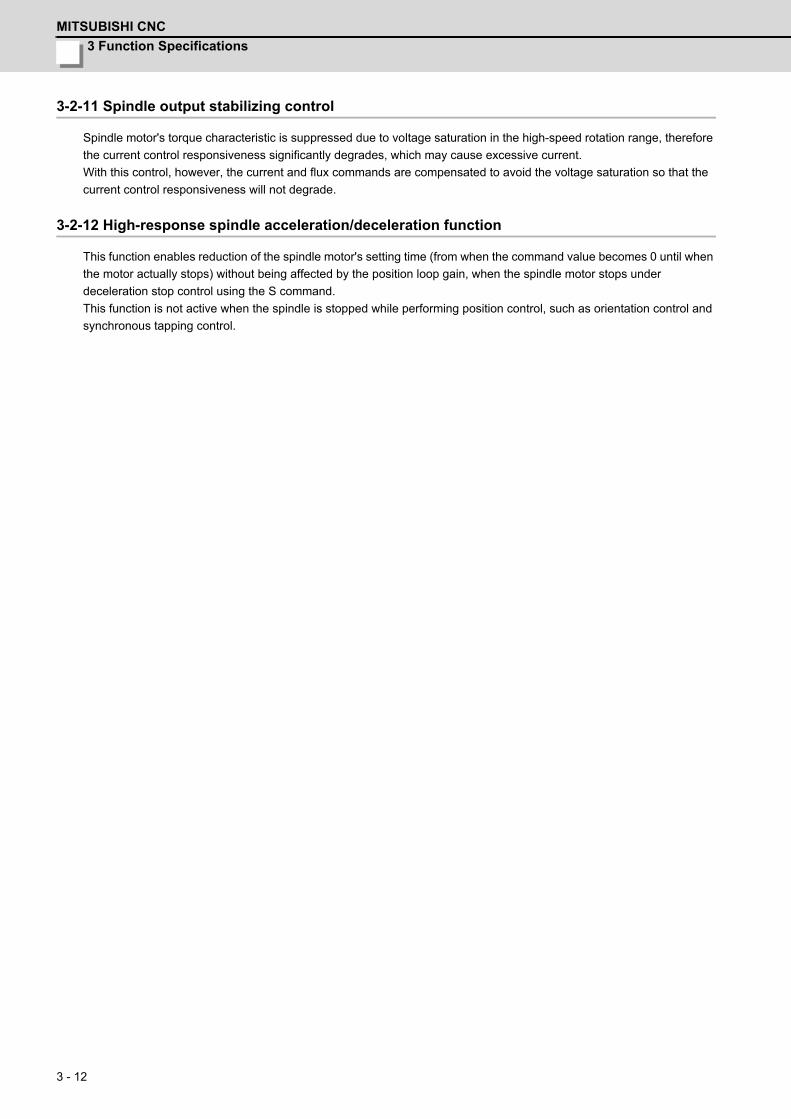
3 Function Specifications
MITSUBISHI CNC
3 - 12
3-2-11 Spindle output stabilizing control
Spindle motor's torque characteristic is suppressed due to voltage saturation in the high-speed rotation range, therefore
the current control responsiveness significantly degrades, which may cause excessive current.
With this control, however, the current and flux commands are compensated to avoid the voltage saturation so that the
current control responsiveness will not degrade.
3-2-12 High-response spindle acceleration/deceleration function
This function enables reduction of the spindle motor's setting time (from when the command value becomes 0 until when
the motor actually stops) without being affected by the position loop gain, when the spindle motor stops under
deceleration stop control using the S command.
This function is not active when the spindle is stopped while performing position control, such as orientation control and
synchronous tapping control.

MDS-D/DH Series Specifications Manual
3-3 Compensation control function
3 - 13
3-3 Compensation control function3-3-1 Jitter compensation
The load inertia becomes much smaller than usual if the motor position enters the machine backlash when the motor is
stopped.
Because this means that an extremely large VGN1 is set for the load inertia, vibration may occur.
Jitter compensation can suppress the vibration that occurs at the motor stop by ignoring the backlash amount of speed
feedback pulses when the speed feedback polarity changes.
3-3-2 Notch filter
This filter can damp vibrations of servo torque commands at a specified frequency.
Machine vibrations can be suppressed by adjusting the notch filter frequency to the machine's resonance frequency.
Filter depth adjustment is also available that allows stable control even when the filter is set to an extremely low
frequency.
<Specifications>
3-3-3 Adaptive tracking-type notch filter
Machine's specific resonance frequency tends to change due to aged deterioration or according to machine's operation
conditions. Therefore, the frequency may be deviated from the filter frequency set at the initial adjustment. With adaptive
tracking-type notch filter, resonance point fluctuation due to the machine's condition change is estimated using the
vibration components of the current commands, and effective notch filter frequency, which has been deviated from the
setting value, is automatically corrected to suppress the resonance.
Notch filter Frequency Depth compensationNotch filter 1 50Hz to 2250Hz EnabledNotch filter 2 50Hz to 2250Hz EnabledNotch filter 3 Fixed at 1125Hz DisabledNotch filter 4 50Hz to 2250Hz EnabledNotch filter 5 50Hz to 2250Hz Enabled
+20
-20
-40
0
+20
-20
-40
0
10 30 50 70 100 300 500 700 1k
10 30 50 70 100 300 500 700 1k
Gain[dB]
Gain[dB]
Frequency [Hz]
Frequency [Hz]
Example of filter characteristic set to 300Hz
For shallow setting by additionally using the depth compensation at 300Hz
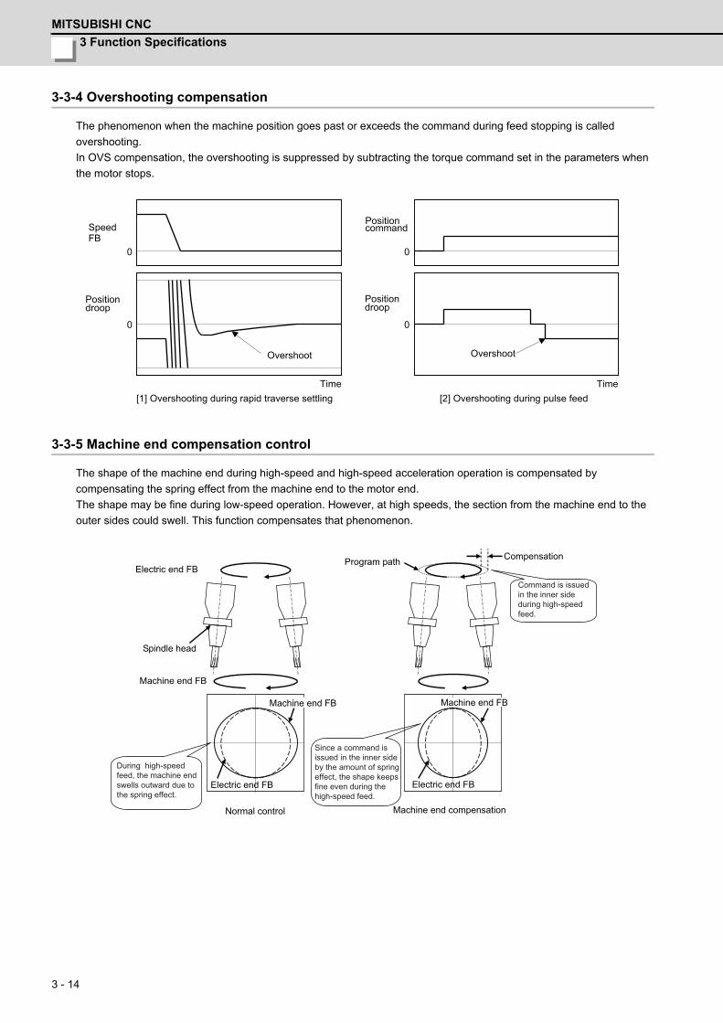
3 Function Specifications
MITSUBISHI CNC
3 - 14
3-3-4 Overshooting compensation
The phenomenon when the machine position goes past or exceeds the command during feed stopping is called
overshooting.
In OVS compensation, the overshooting is suppressed by subtracting the torque command set in the parameters when
the motor stops.
3-3-5 Machine end compensation control
The shape of the machine end during high-speed and high-speed acceleration operation is compensated by
compensating the spring effect from the machine end to the motor end.
The shape may be fine during low-speed operation. However, at high speeds, the section from the machine end to the
outer sides could swell. This function compensates that phenomenon.
0
0
0
0
Position command
Position droop
Time
Overshoot
Speed FB
Position droop
Time
Overshoot
[1] Overshooting during rapid traverse settling [2] Overshooting during pulse feed
Compensation
Electric end FB
Machine end FB
Electric end FB
Normal control
Machine end FB
Machine end compensation
Electric end FB
Machine end FB
Spindle head
Program path
Command is issued in the inner side during high-speed feed.
During high-speed feed, the machine end swells outward due to the spring effect.
Since a command is issued in the inner side by the amount of spring effect, the shape keeps fine even during the high-speed feed.
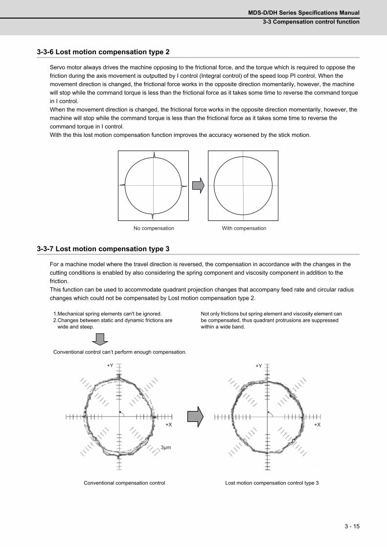
MDS-D/DH Series Specifications Manual
3-3 Compensation control function
3 - 15
3-3-6 Lost motion compensation type 2
Servo motor always drives the machine opposing to the frictional force, and the torque which is required to oppose the
friction during the axis movement is outputted by I control (Integral control) of the speed loop PI control. When the
movement direction is changed, the frictional force works in the opposite direction momentarily, however, the machine
will stop while the command torque is less than the frictional force as it takes some time to reverse the command torque
in I control.
When the movement direction is changed, the frictional force works in the opposite direction momentarily, however, the
machine will stop while the command torque is less than the frictional force as it takes some time to reverse the
command torque in I control.
With the this lost motion compensation function improves the accuracy worsened by the stick motion.
3-3-7 Lost motion compensation type 3
For a machine model where the travel direction is reversed, the compensation in accordance with the changes in the
cutting conditions is enabled by also considering the spring component and viscosity component in addition to the
friction.
This function can be used to accommodate quadrant projection changes that accompany feed rate and circular radius
changes which could not be compensated by Lost motion compensation type 2.
1.Mechanical spring elements can't be ignored.2.Changes between static and dynamic frictions are wide and steep.
Not only frictions but spring element and viscosity element can be compensated, thus quadrant protrusions are suppressed within a wide band.
Conventional control can’t perform enough compensation.
Conventional compensation control Lost motion compensation control type 3
No compensation With compensation
+Y +Y
+X +X
3μm

3 Function Specifications
MITSUBISHI CNC
3 - 16
3-3-8 Lost motion compensation type 4
When the difference between static and dynamic friction is large, the friction torque changes sharply at the inversion of
the travel direction. When the lost motion type 4 is used together with the type 2 or type 3, the acute change of the
friction torque is compensated so that the path accuracy at the travel direction inversion can be enhanced.
3-3-9 Spindle motor temperature compensation function
As for the low-temperature state of the IM spindle motor, the output characteristic may deteriorate in comparison with the
warm-up state and the acceleration/deceleration time may become long, or the load display during cutting may become
high immediately after operation. This function performs the control compensation depending on the motor temperature
with the thermistor built into the spindle motor and suppresses the output characteristic deterioration when the
temperature is low. Temperature compensation function is not required for IPM spindle motor in principle.
1.50
1.60
1.70
1.80
1.90
2.00
2.10
2.20
2.30
2.40
2.50
10020 40 60 80Stator (thermistor) temperature[]
S120
00 A
ccel
erat
ion/
dec
eler
atio
n ti
me[s] With compensation
[Acceleration]With compensation[Deceleration]
Without compensation[Acceleration]Without compensation[Deceleration]
Effect of suppressingacceleration/deceleration
time fluctuation
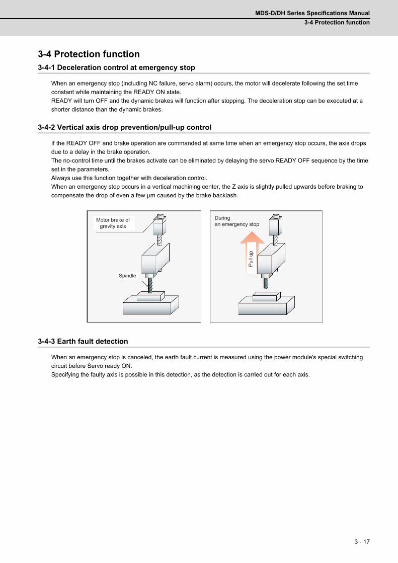
MDS-D/DH Series Specifications Manual
3-4 Protection function
3 - 17
3-4 Protection function3-4-1 Deceleration control at emergency stop
When an emergency stop (including NC failure, servo alarm) occurs, the motor will decelerate following the set time
constant while maintaining the READY ON state.
READY will turn OFF and the dynamic brakes will function after stopping. The deceleration stop can be executed at a
shorter distance than the dynamic brakes.
3-4-2 Vertical axis drop prevention/pull-up control
If the READY OFF and brake operation are commanded at same time when an emergency stop occurs, the axis drops
due to a delay in the brake operation.
The no-control time until the brakes activate can be eliminated by delaying the servo READY OFF sequence by the time
set in the parameters.
Always use this function together with deceleration control.
When an emergency stop occurs in a vertical machining center, the Z axis is slightly pulled upwards before braking to
compensate the drop of even a few μm caused by the brake backlash.
3-4-3 Earth fault detection
When an emergency stop is canceled, the earth fault current is measured using the power module's special switching
circuit before Servo ready ON.
Specifying the faulty axis is possible in this detection, as the detection is carried out for each axis.
Spindle
During an emergency stop
Motor brake of gravity axis
Pul
l up

3 Function Specifications
MITSUBISHI CNC
3 - 18
3-4-4 Collision detection function
Collision detection function quickly detects a collision of the motor shaft, and decelerates and stops the motor. This
suppresses the generation of an excessive torque in the machine tool, and helps to prevent an abnormal state from
occurring.Impact at a collision will not be prevented by using this collision detection function, so this function does not
necessarily guarantee that the machine tool will not be damaged or that the machine accuracy will be maintained after a
collision.
The same caution as during regular operation is required to prevent the machine from colliding.
3-4-5 Safety observation function
This function is aimed at allowing a safety access to the machine's working part by opening the protection door, etc.
without shutting the power for saving the setup time.
Both the NC control system and drive system (servo and spindle drive units) doubly observe the axis feed rate so that it
will not exceed the safety speed. If it exceeds the set safety speed, emergency stop occurs and the power is shut OFF.
3-4-6 Fan stop detection
The rotation of the radiation fin cooling fan is observed and when the fan stops rotating for a breakdown of the fan or an
external factor, warning is detected.(The system will not be stopped.) Before sudden system down by the power module
overheat, inspection and replacement of the fan are prompted.
3-4-7 Open-phase detection
Disconnection of a phase of the 3-phase input power is detected.
The occurrence of abnormal operation will be avoided by open-phase detection because open-phase does not cause a
power failure, however, abnormal operation will occur when the motor load becomes large.
3-4-8 Contactor weld detection
It detects that a contact of the external contactor is welding and cannot be opened.
Collision detection function outline
(a) A collision of machine is detected. (b) A retracting torque is generated. The collision of machine is reduced.
Motor encoderCurrent command
Speed F/B
Drive CPUNC CPU
FB speed observationFB speed observation
Command speed observation
Command speed observation
Speed observation Speed observation
Servo control
Positionspeed
command
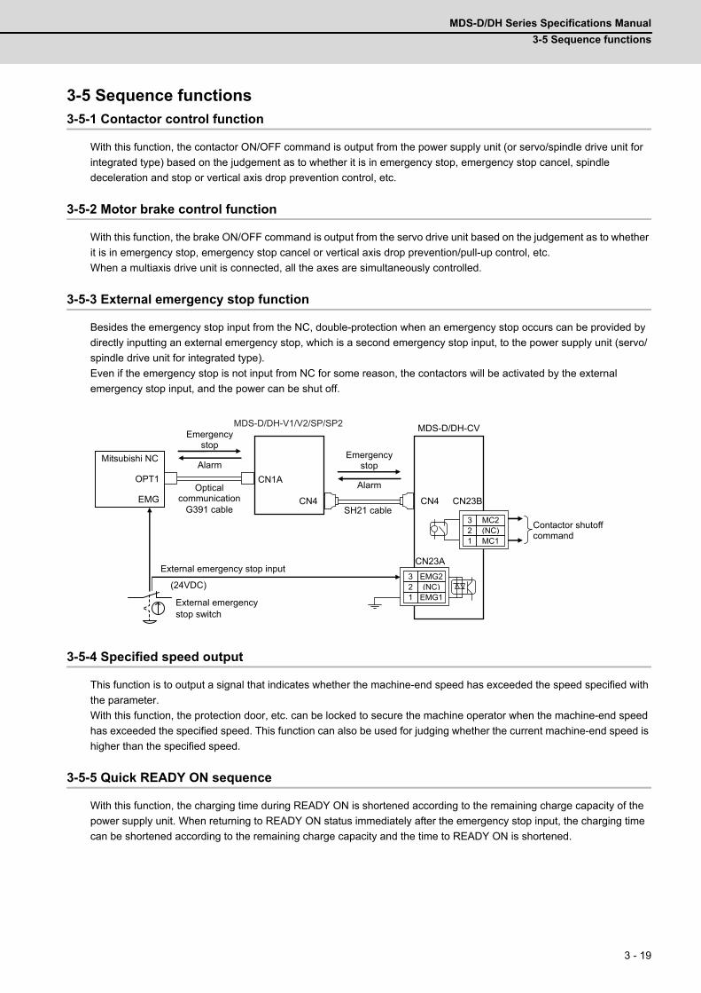
MDS-D/DH Series Specifications Manual
3-5 Sequence functions
3 - 19
3-5 Sequence functions3-5-1 Contactor control function
With this function, the contactor ON/OFF command is output from the power supply unit (or servo/spindle drive unit for
integrated type) based on the judgement as to whether it is in emergency stop, emergency stop cancel, spindle
deceleration and stop or vertical axis drop prevention control, etc.
3-5-2 Motor brake control function
With this function, the brake ON/OFF command is output from the servo drive unit based on the judgement as to whether
it is in emergency stop, emergency stop cancel or vertical axis drop prevention/pull-up control, etc.
When a multiaxis drive unit is connected, all the axes are simultaneously controlled.
3-5-3 External emergency stop function
Besides the emergency stop input from the NC, double-protection when an emergency stop occurs can be provided by
directly inputting an external emergency stop, which is a second emergency stop input, to the power supply unit (servo/
spindle drive unit for integrated type).
Even if the emergency stop is not input from NC for some reason, the contactors will be activated by the external
emergency stop input, and the power can be shut off.
3-5-4 Specified speed output
This function is to output a signal that indicates whether the machine-end speed has exceeded the speed specified with
the parameter.
With this function, the protection door, etc. can be locked to secure the machine operator when the machine-end speed
has exceeded the specified speed. This function can also be used for judging whether the current machine-end speed is
higher than the specified speed.
3-5-5 Quick READY ON sequence
With this function, the charging time during READY ON is shortened according to the remaining charge capacity of the
power supply unit. When returning to READY ON status immediately after the emergency stop input, the charging time
can be shortened according to the remaining charge capacity and the time to READY ON is shortened.
CN1A
CN4
MDS-D/DH-CV
CN4
3 EMG2 2 (NC) 1 EMG1
CN23B
CN23A
OPT1
3 MC2 2 (NC) 1 MC1
EMG
MDS-D/DH-V1/V2/SP/SP2
SH21 cable
(24VDC)
External emergency stop switch
External emergency stop input
Mitsubishi NC
G391 cable
Alarm
Emergency stop
Optical communication
Emergency stop
Alarm
Contactor shutoff command
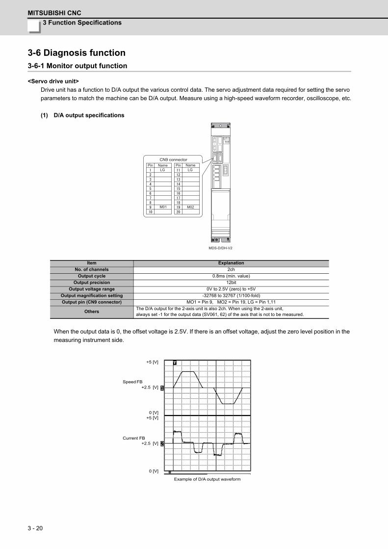
3 Function Specifications
MITSUBISHI CNC
3 - 20
3-6 Diagnosis function3-6-1 Monitor output function
<Servo drive unit>
Drive unit has a function to D/A output the various control data. The servo adjustment data required for setting the servo
parameters to match the machine can be D/A output. Measure using a high-speed waveform recorder, oscilloscope, etc.
(1) D/A output specifications
When the output data is 0, the offset voltage is 2.5V. If there is an offset voltage, adjust the zero level position in the
measuring instrument side.
Item Explanation
No. of channels 2ch
Output cycle 0.8ms (min. value)
Output precision 12bit
Output voltage range 0V to 2.5V (zero) to +5V
Output magnification setting -32768 to 32767 (1/100-fold)
Output pin (CN9 connector) MO1 = Pin 9, MO2 = Pin 19, LG = Pin 1,11
OthersThe D/A output for the 2-axis unit is also 2ch. When using the 2-axis unit,always set -1 for the output data (SV061, 62) of the axis that is not to be measured.
MDS-D/DH-V2
CN9 connectorPin Pin NameName
LGLG
M01 M02
+2.5 [V]
0 [V]
Speed FB
Current FB
+2.5 [V]
0 [V]+5 [V]
+5 [V]
Example of D/A output waveform
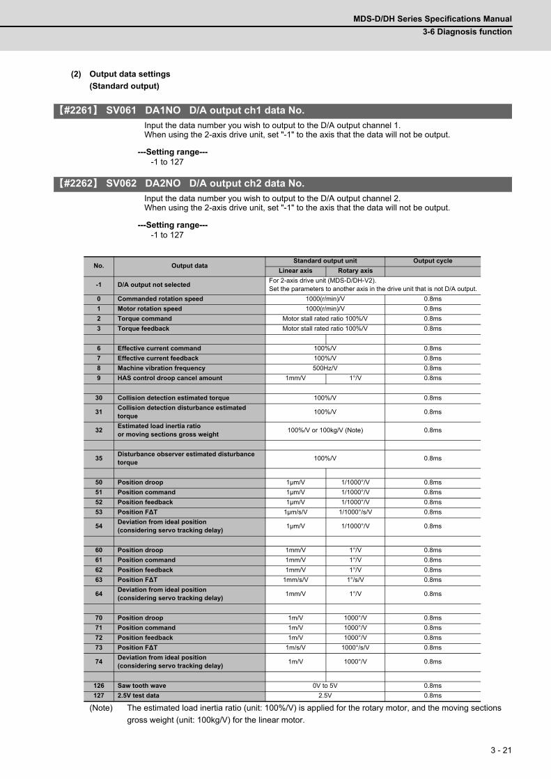
MDS-D/DH Series Specifications Manual
3-6 Diagnosis function
3 - 21
(2) Output data settings
(Standard output)
【#2261】 SV061 DA1NO D/A output ch1 data No.
Input the data number you wish to output to the D/A output channel 1. When using the 2-axis drive unit, set "-1" to the axis that the data will not be output.
---Setting range----1 to 127
【#2262】 SV062 DA2NO D/A output ch2 data No.
Input the data number you wish to output to the D/A output channel 2. When using the 2-axis drive unit, set "-1" to the axis that the data will not be output.
---Setting range----1 to 127
(Note) The estimated load inertia ratio (unit: 100%/V) is applied for the rotary motor, and the moving sections
gross weight (unit: 100kg/V) for the linear motor.
No. Output dataStandard output unit Output cycle
Linear axis Rotary axis
-1 D/A output not selectedFor 2-axis drive unit (MDS-D/DH-V2).Set the parameters to another axis in the drive unit that is not D/A output.
0 Commanded rotation speed 1000(r/min)/V 0.8ms
1 Motor rotation speed 1000(r/min)/V 0.8ms
2 Torque command Motor stall rated ratio 100%/V 0.8ms
3 Torque feedback Motor stall rated ratio 100%/V 0.8ms
6 Effective current command 100%/V 0.8ms
7 Effective current feedback 100%/V 0.8ms
8 Machine vibration frequency 500Hz/V 0.8ms
9 HAS control droop cancel amount 1mm/V 1°/V 0.8ms
30 Collision detection estimated torque 100%/V 0.8ms
31Collision detection disturbance estimated torque
100%/V 0.8ms
32Estimated load inertia ratioor moving sections gross weight
100%/V or 100kg/V (Note) 0.8ms
35Disturbance observer estimated disturbance torque
100%/V 0.8ms
50 Position droop 1μm/V 1/1000°/V 0.8ms
51 Position command 1μm/V 1/1000°/V 0.8ms
52 Position feedback 1μm/V 1/1000°/V 0.8ms
53 Position F∆T 1μm/s/V 1/1000°/s/V 0.8ms
54Deviation from ideal position(considering servo tracking delay)
1μm/V 1/1000°/V 0.8ms
60 Position droop 1mm/V 1°/V 0.8ms
61 Position command 1mm/V 1°/V 0.8ms
62 Position feedback 1mm/V 1°/V 0.8ms
63 Position F∆T 1mm/s/V 1°/s/V 0.8ms
64Deviation from ideal position(considering servo tracking delay)
1mm/V 1°/V 0.8ms
70 Position droop 1m/V 1000°/V 0.8ms
71 Position command 1m/V 1000°/V 0.8ms
72 Position feedback 1m/V 1000°/V 0.8ms
73 Position F∆T 1m/s/V 1000°/s/V 0.8ms
74Deviation from ideal position(considering servo tracking delay)
1m/V 1000°/V 0.8ms
126 Saw tooth wave 0V to 5V 0.8ms
127 2.5V test data 2.5V 0.8ms
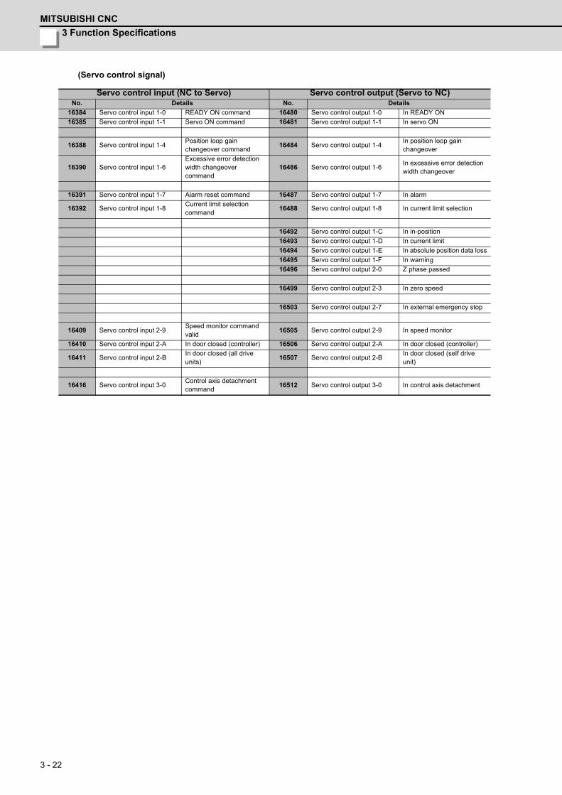
3 Function Specifications
MITSUBISHI CNC
3 - 22
(Servo control signal)
Servo control input (NC to Servo) Servo control output (Servo to NC)No. Details No. Details
16384 Servo control input 1-0 READY ON command 16480 Servo control output 1-0 In READY ON
16385 Servo control input 1-1 Servo ON command 16481 Servo control output 1-1 In servo ON
16388 Servo control input 1-4Position loop gain changeover command
16484 Servo control output 1-4In position loop gain changeover
16390 Servo control input 1-6Excessive error detection width changeover command
16486 Servo control output 1-6In excessive error detection width changeover
16391 Servo control input 1-7 Alarm reset command 16487 Servo control output 1-7 In alarm
16392 Servo control input 1-8Current limit selection command
16488 Servo control output 1-8 In current limit selection
16492 Servo control output 1-C In in-position
16493 Servo control output 1-D In current limit
16494 Servo control output 1-E In absolute position data loss
16495 Servo control output 1-F In warning
16496 Servo control output 2-0 Z phase passed
16499 Servo control output 2-3 In zero speed
16503 Servo control output 2-7 In external emergency stop
16409 Servo control input 2-9Speed monitor command valid
16505 Servo control output 2-9 In speed monitor
16410 Servo control input 2-A In door closed (controller) 16506 Servo control output 2-A In door closed (controller)
16411 Servo control input 2-BIn door closed (all drive units)
16507 Servo control output 2-BIn door closed (self drive unit)
16416 Servo control input 3-0Control axis detachment command
16512 Servo control output 3-0 In control axis detachment
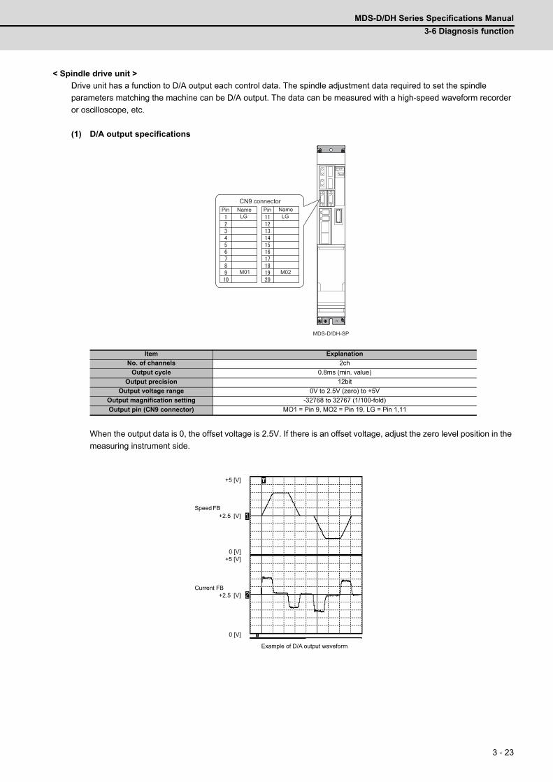
MDS-D/DH Series Specifications Manual
3-6 Diagnosis function
3 - 23
< Spindle drive unit >
Drive unit has a function to D/A output each control data. The spindle adjustment data required to set the spindle
parameters matching the machine can be D/A output. The data can be measured with a high-speed waveform recorder
or oscilloscope, etc.
(1) D/A output specifications
When the output data is 0, the offset voltage is 2.5V. If there is an offset voltage, adjust the zero level position in the
measuring instrument side.
Item Explanation
No. of channels 2ch
Output cycle 0.8ms (min. value)
Output precision 12bit
Output voltage range 0V to 2.5V (zero) to +5V
Output magnification setting -32768 to 32767 (1/100-fold)
Output pin (CN9 connector) MO1 = Pin 9, MO2 = Pin 19, LG = Pin 1,11
MDS-D/DH-SP
CN9 connectorPin Pin NameName
LGLG
M01 M02
+2.5 [V]
0 [V]
Speed FB
Current FB
+2.5 [V]
0 [V]+5 [V]
+5 [V]Scroll
Memory
Example of D/A output waveform
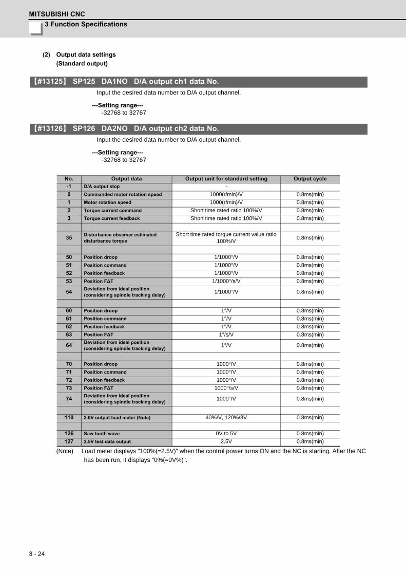
3 Function Specifications
MITSUBISHI CNC
3 - 24
(2) Output data settings
(Standard output)
【#13125】 SP125 DA1NO D/A output ch1 data No.
Input the desired data number to D/A output channel.
---Setting range----32768 to 32767
【#13126】 SP126 DA2NO D/A output ch2 data No.
Input the desired data number to D/A output channel.
---Setting range----32768 to 32767
(Note) Load meter displays "100%(=2.5V)" when the control power turns ON and the NC is starting. After the NC
has been run, it displays "0%(=0V%)".
No. Output data Output unit for standard setting Output cycle
-1 D/A output stop -
0 Commanded motor rotation speed 1000(r/min)/V 0.8ms(min)
1 Motor rotation speed 1000(r/min)/V 0.8ms(min)
2 Torque current command Short time rated ratio 100%/V 0.8ms(min)
3 Torque current feedback Short time rated ratio 100%/V 0.8ms(min)
35Disturbance observer estimated disturbance torque
Short time rated torque current value ratio 100%/V
0.8ms(min)
50 Position droop 1/1000°/V 0.8ms(min)
51 Position command 1/1000°/V 0.8ms(min)
52 Position feedback 1/1000°/V 0.8ms(min)
53 Position F∆T 1/1000°/s/V 0.8ms(min)
54Deviation from ideal position(considering spindle tracking delay)
1/1000°/V 0.8ms(min)
60 Position droop 1°/V 0.8ms(min)
61 Position command 1°/V 0.8ms(min)
62 Position feedback 1°/V 0.8ms(min)
63 Position F∆T 1°/s/V 0.8ms(min)
64Deviation from ideal position(considering spindle tracking delay)
1°/V 0.8ms(min)
70 Position droop 1000°/V 0.8ms(min)
71 Position command 1000°/V 0.8ms(min)
72 Position feedback 1000°/V 0.8ms(min)
73 Position F∆T 1000°/s/V 0.8ms(min)
74Deviation from ideal position(considering spindle tracking delay)
1000°/V 0.8ms(min)
110 3.0V output load meter (Note) 40%/V, 120%/3V 0.8ms(min)
126 Saw tooth wave 0V to 5V 0.8ms(min)
127 2.5V test data output 2.5V 0.8ms(min)
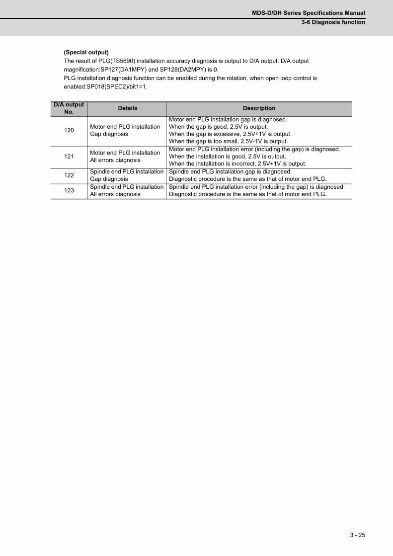
MDS-D/DH Series Specifications Manual
3-6 Diagnosis function
3 - 25
(Special output)
The result of PLG(TS5690) installation accuracy diagnosis is output to D/A output. D/A output
magnification:SP127(DA1MPY) and SP128(DA2MPY) is 0.
PLG installation diagnosis function can be enabled during the rotation, when open loop control is
enabled:SP018(SPEC2)/bit1=1.
D/A output No.
Details Description
120Motor end PLG installationGap diagnosis
Motor end PLG installation gap is diagnosed.When the gap is good, 2.5V is output.When the gap is excessive, 2.5V+1V is output.When the gap is too small, 2.5V-1V is output.
121Motor end PLG installationAll errors diagnosis
Motor end PLG installation error (including the gap) is diagnosed.When the installation is good, 2.5V is output.When the installation is incorrect, 2.5V+1V is output.
122Spindle end PLG installationGap diagnosis
Spindle end PLG installation gap is diagnosed.Diagnostic procedure is the same as that of motor end PLG.
123Spindle end PLG installationAll errors diagnosis
Spindle end PLG installation error (including the gap) is diagnosed.Diagnostic procedure is the same as that of motor end PLG.
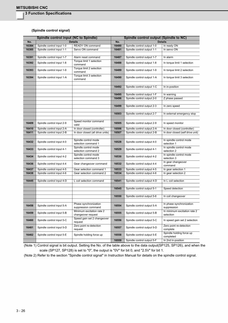
3 Function Specifications
MITSUBISHI CNC
3 - 26
(Spindle control signal)
(Note 1) Control signal is bit output. Setting the No. of the table above to the data output(SP125, SP126), and when the
scale (SP127, SP128) is set to "0", the output is "0V" for bit 0, and "2.5V" for bit 1.
(Note 2) Refer to the section "Spindle control signal" in Instruction Manual for details on the spindle control signal.
Spindle control input (NC to Spindle) Spindle control output (Spindle to NC)No. Details No. Details
16384 Spindle control input 1-0 READY ON command 16480 Spindle control output 1-0 In ready ON
16385 Spindle control input 1-1 Servo ON command 16481 Spindle control output 1-1 In servo ON
16391 Spindle control input 1-7 Alarm reset command 16487 Spindle control output 1-7 In alarm
16392 Spindle control input 1-8Torque limit 1 selection command
16488 Spindle control output 1-8 In torque limit 1 selection
16393 Spindle control input 1-9Torque limit 2 selection command
16489 Spindle control output 1-9 In torque limit 2 selection
16394 Spindle control input 1-ATorque limit 3 selection command
16490 Spindle control output 1-A In torque limit 3 selection
16492 Spindle control output 1-C In in-position
16495 Spindle control output 1-F In warning
16496 Spindle control output 2-0 Z phase passed
16499 Spindle control output 2-3 In zero speed
16503 Spindle control output 2-7 In external emergency stop
16409 Spindle control input 2-9Speed monitor command valid
16505 Spindle control output 2-9 In speed monitor
16410 Spindle control input 2-A In door closed (controller) 16506 Spindle control output 2-A In door closed (controller)
16411 Spindle control input 2-B In door closed (all drive units) 16507 Spindle control output 2-B In door closed (self drive unit)
16432 Spindle control input 4-0Spindle control mode selection command 1
16528 Spindle control output 4-0In spindle control mode selection 1
16433 Spindle control input 4-1Spindle control mode selection command 2
16529 Spindle control output 4-1In spindle control mode selection 2
16434 Spindle control input 4-2Spindle control mode selection command 3
16530 Spindle control output 4-2In spindle control mode selection 3
16436 Spindle control input 4-4 Gear changeover command 16532 Spindle control output 4-4In gear changeover command
16437 Spindle control input 4-5 Gear selection command 1 16533 Spindle control output 4-5 In gear selection 1
16438 Spindle control input 4-6 Gear selection command 2 16534 Spindle control output 4-6 In gear selection 2
16445 Spindle control input 4-D L coil selection command 16541 Spindle control output 4-D In L coil selection
16545 Spindle control output 5-1 Speed detection
16550 Spindle control output 5-6 In coil changeover
16458 Spindle control input 5-APhase synchronization suppression command
16554 Spindle control output 5-AIn phase synchronization suppression
16459 Spindle control input 5-BMinimum excitation rate 2 changeover request
16555 Spindle control output 5-BIn minimum excitation rate 2 selection
16460 Spindle control input 5-CSpeed gain set 2 changeover request
16556 Spindle control output 5-C In speed gain set 2 selection
16461 Spindle control input 5-DZero point re-detection request
16557 Spindle control output 5-DZero point re-detection complete
16462 Spindle control input 5-E Spindle holding force up 16558 Spindle control output 5-ESpindle holding force up completed
16559 Spindle control output 5-F In 2nd in-position

MDS-D/DH Series Specifications Manual
3-6 Diagnosis function
3 - 27
3-6-2 Machine resonance frequency display function
If resonance is generated and it causes vibrations of the current commands, this function estimates the vibration
frequency and displays it on the NC monitor screen (AFLT frequency).
This is useful in setting the notch filter frequencies during servo adjustment. This function constantly operates with no
need of parameter setting.
3-6-3 Machine inertia display function
With this function, the load current and acceleration rate during motor acceleration are measured to estimate the load
inertia.
According to the parameter setting, the estimated load inertia is displayed on the NC monitor screen, expressed as its
percentage to the motor inertia.
3-6-4 Motor temperature display function
The temperature sensed by the thermal sensor attached to the motor coil is displayed on the NC screen.
(Note) This function is only compatible with Spindle motor.
3-6-5 Load monitor output function
A spindle motor's load is output as an analog voltage of 0 to 3V (0 to 120%). To use this function, connect a load meter
that meets the specifications.
3-6-6 Open loop control function
This function is to run a spindle motor for operation check before or during the adjustment of the spindle motor's encoder.
This allows the operation in which no encoder feedback signals are used.
3-6-7 Power supply voltage display function
The converter bus voltage in main circuit power is displayed on the NC monitor screen.

3 Function Specifications
MITSUBISHI CNC
3 - 28

4 - 1
4
Characteristics
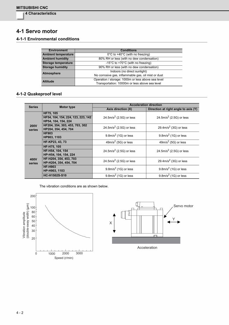
4 Characteristics
MITSUBISHI CNC
4 - 2
4-1 Servo motor4-1-1 Environmental conditions
4-1-2 Quakeproof level
The vibration conditions are as shown below.
Environment ConditionsAmbient temperature 0°C to +40°C (with no freezing)Ambient humidity 80% RH or less (with no dew condensation)Storage temperature -15°C to +70°C (with no freezing)Storage humidity 90% RH or less (with no dew condensation)
AtmosphereIndoors (no direct sunlight)
No corrosive gas, inflammable gas, oil mist or dust
AltitudeOperation / storage: 1000m or less above sea level
Transportation: 10000m or less above sea level
Series Motor typeAcceleration direction
Axis direction (X) Direction at right angle to axis (Y)
200Vseries
HF75, 105
24.5m/s2 (2.5G) or less 24.5m/s2 (2.5G) or lessHF54, 104, 154, 224, 123, 223, 142HP54, 104, 154, 224HF204, 354, 303, 453, 703, 302HP204, 354, 454, 704 24.5m/s2 (2.5G) or less 29.4m/s2 (3G) or less
HF903HP903, 1103 9.8m/s2 (1G) or less 9.8m/s2 (1G) or less
HF-KP23, 43, 73 49m/s2 (5G) or less 49m/s2 (5G) or less
400Vseries
HF-H75, 105
24.5m/s2 (2.5G) or less 24.5m/s2 (2.5G) or lessHF-H54, 104, 154HP-H54, 104, 154, 224HF-H204, 354, 453, 703HP-H204, 354, 454, 704 24.5m/s2 (2.5G) or less 29.4m/s2 (3G) or less
HF-H903HP-H903, 1103 9.8m/s2 (1G) or less 9.8m/s2 (1G) or less
HC-H1502S-S10 9.8m/s2 (1G) or less 9.8m/s2 (1G) or less
Speed (r/min)0 1000 2000 3000
Vibr
atio
n am
plitu
de
(dou
ble-
sway
wid
th) (
μm
)
20
3040506080
100
200
YX
Servo motor
Acceleration
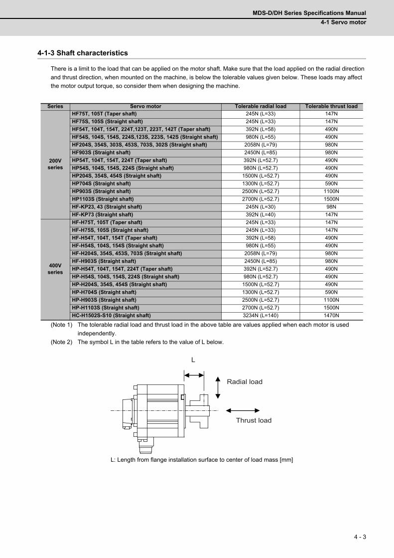
MDS-D/DH Series Specifications Manual
4-1 Servo motor
4 - 3
4-1-3 Shaft characteristics
There is a limit to the load that can be applied on the motor shaft. Make sure that the load applied on the radial direction
and thrust direction, when mounted on the machine, is below the tolerable values given below. These loads may affect
the motor output torque, so consider them when designing the machine.
(Note 1) The tolerable radial load and thrust load in the above table are values applied when each motor is used
independently.
(Note 2) The symbol L in the table refers to the value of L below.
L: Length from flange installation surface to center of load mass [mm]
Series Servo motor Tolerable radial load Tolerable thrust load
200Vseries
HF75T, 105T (Taper shaft) 245N (L=33) 147N
HF75S, 105S (Straight shaft) 245N (L=33) 147N
HF54T, 104T, 154T, 224T,123T, 223T, 142T (Taper shaft) 392N (L=58) 490N
HF54S, 104S, 154S, 224S,123S, 223S, 142S (Straight shaft) 980N (L=55) 490N
HF204S, 354S, 303S, 453S, 703S, 302S (Straight shaft) 2058N (L=79) 980N
HF903S (Straight shaft) 2450N (L=85) 980N
HP54T, 104T, 154T, 224T (Taper shaft) 392N (L=52.7) 490N
HP54S, 104S, 154S, 224S (Straight shaft) 980N (L=52.7) 490N
HP204S, 354S, 454S (Straight shaft) 1500N (L=52.7) 490N
HP704S (Straight shaft) 1300N (L=52.7) 590N
HP903S (Straight shaft) 2500N (L=52.7) 1100N
HP1103S (Straight shaft) 2700N (L=52.7) 1500N
HF-KP23, 43 (Straight shaft) 245N (L=30) 98N
HF-KP73 (Straight shaft) 392N (L=40) 147N
400Vseries
HF-H75T, 105T (Taper shaft) 245N (L=33) 147N
HF-H75S, 105S (Straight shaft) 245N (L=33) 147N
HF-H54T, 104T, 154T (Taper shaft) 392N (L=58) 490N
HF-H54S, 104S, 154S (Straight shaft) 980N (L=55) 490N
HF-H204S, 354S, 453S, 703S (Straight shaft) 2058N (L=79) 980N
HF-H903S (Straight shaft) 2450N (L=85) 980N
HP-H54T, 104T, 154T, 224T (Taper shaft) 392N (L=52.7) 490N
HP-H54S, 104S, 154S, 224S (Straight shaft) 980N (L=52.7) 490N
HP-H204S, 354S, 454S (Straight shaft) 1500N (L=52.7) 490N
HP-H704S (Straight shaft) 1300N (L=52.7) 590N
HP-H903S (Straight shaft) 2500N (L=52.7) 1100N
HP-H1103S (Straight shaft) 2700N (L=52.7) 1500N
HC-H1502S-S10 (Straight shaft) 3234N (L=140) 1470N
Radial load
Thrust load
L
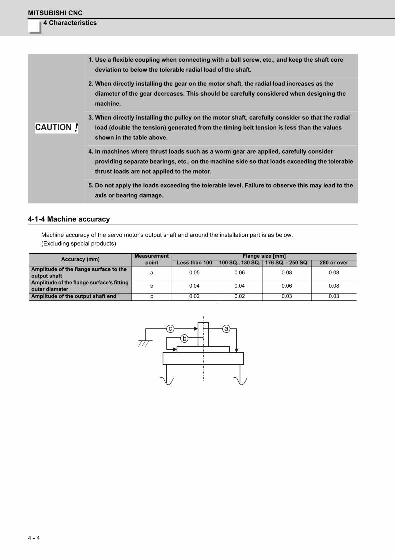
4 Characteristics
MITSUBISHI CNC
4 - 4
4-1-4 Machine accuracy
Machine accuracy of the servo motor's output shaft and around the installation part is as below.
(Excluding special products)
1. Use a flexible coupling when connecting with a ball screw, etc., and keep the shaft core
deviation to below the tolerable radial load of the shaft.
2. When directly installing the gear on the motor shaft, the radial load increases as the
diameter of the gear decreases. This should be carefully considered when designing the
machine.
3. When directly installing the pulley on the motor shaft, carefully consider so that the radial
load (double the tension) generated from the timing belt tension is less than the values
shown in the table above.
4. In machines where thrust loads such as a worm gear are applied, carefully consider
providing separate bearings, etc., on the machine side so that loads exceeding the tolerable
thrust loads are not applied to the motor.
5. Do not apply the loads exceeding the tolerable level. Failure to observe this may lead to the
axis or bearing damage.
Accuracy (mm)Measurement
pointFlange size [mm]
Less than 100 100 SQ., 130 SQ. 176 SQ. - 250 SQ. 280 or overAmplitude of the flange surface to the output shaft
a 0.05 0.06 0.08 0.08
Amplitude of the flange surface's fitting outer diameter
b 0.04 0.04 0.06 0.08
Amplitude of the output shaft end c 0.02 0.02 0.03 0.03
CAUTION
a cb
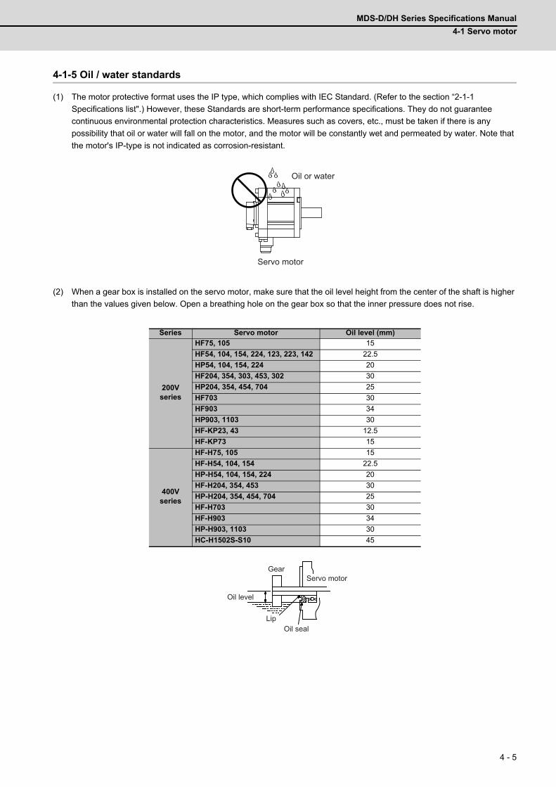
MDS-D/DH Series Specifications Manual
4-1 Servo motor
4 - 5
4-1-5 Oil / water standards
(1) The motor protective format uses the IP type, which complies with IEC Standard. (Refer to the section “2-1-1
Specifications list".) However, these Standards are short-term performance specifications. They do not guarantee
continuous environmental protection characteristics. Measures such as covers, etc., must be taken if there is any
possibility that oil or water will fall on the motor, and the motor will be constantly wet and permeated by water. Note that
the motor's IP-type is not indicated as corrosion-resistant.
(2) When a gear box is installed on the servo motor, make sure that the oil level height from the center of the shaft is higher
than the values given below. Open a breathing hole on the gear box so that the inner pressure does not rise.
Series Servo motor Oil level (mm)
200Vseries
HF75, 105 15
HF54, 104, 154, 224, 123, 223, 142 22.5
HP54, 104, 154, 224 20
HF204, 354, 303, 453, 302 30
HP204, 354, 454, 704 25
HF703 30
HF903 34
HP903, 1103 30
HF-KP23, 43 12.5
HF-KP73 15
400Vseries
HF-H75, 105 15
HF-H54, 104, 154 22.5
HP-H54, 104, 154, 224 20
HF-H204, 354, 453 30
HP-H204, 354, 454, 704 25
HF-H703 30
HF-H903 34
HP-H903, 1103 30
HC-H1502S-S10 45
Oil or water
Servo motor
GearServo motor
Oil seal
Oil level
Lip
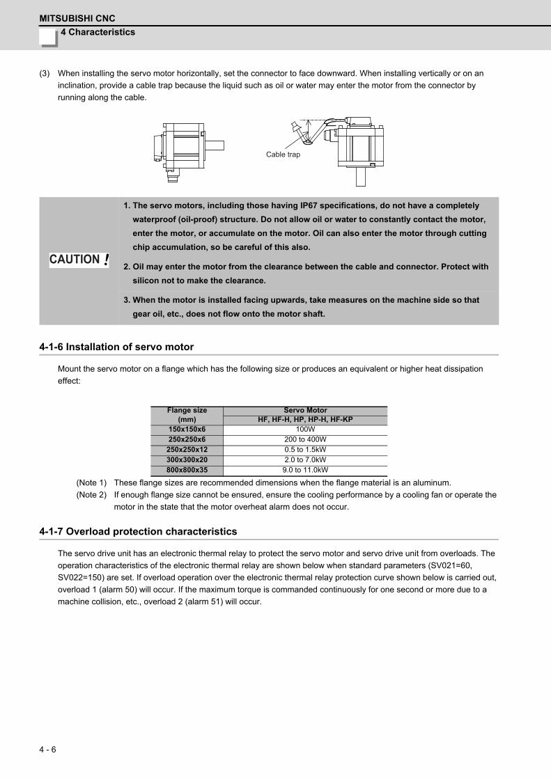
4 Characteristics
MITSUBISHI CNC
4 - 6
(3) When installing the servo motor horizontally, set the connector to face downward. When installing vertically or on an
inclination, provide a cable trap because the liquid such as oil or water may enter the motor from the connector by
running along the cable.
4-1-6 Installation of servo motor
Mount the servo motor on a flange which has the following size or produces an equivalent or higher heat dissipation
effect:
(Note 1) These flange sizes are recommended dimensions when the flange material is an aluminum.
(Note 2) If enough flange size cannot be ensured, ensure the cooling performance by a cooling fan or operate the
motor in the state that the motor overheat alarm does not occur.
4-1-7 Overload protection characteristics
The servo drive unit has an electronic thermal relay to protect the servo motor and servo drive unit from overloads. The
operation characteristics of the electronic thermal relay are shown below when standard parameters (SV021=60,
SV022=150) are set. If overload operation over the electronic thermal relay protection curve shown below is carried out,
overload 1 (alarm 50) will occur. If the maximum torque is commanded continuously for one second or more due to a
machine collision, etc., overload 2 (alarm 51) will occur.
1. The servo motors, including those having IP67 specifications, do not have a completely
waterproof (oil-proof) structure. Do not allow oil or water to constantly contact the motor,
enter the motor, or accumulate on the motor. Oil can also enter the motor through cutting
chip accumulation, so be careful of this also.
2. Oil may enter the motor from the clearance between the cable and connector. Protect with
silicon not to make the clearance.
3. When the motor is installed facing upwards, take measures on the machine side so that
gear oil, etc., does not flow onto the motor shaft.
Flange size(mm)
Servo MotorHF, HF-H, HP, HP-H, HF-KP
150x150x6 100W250x250x6 200 to 400W250x250x12 0.5 to 1.5kW300x300x20 2.0 to 7.0kW800x800x35 9.0 to 11.0kW
Cable trap
CAUTION

MDS-D/DH Series Specifications Manual
4-1 Servo motor
4 - 7
(1) 200V series
< HF series >
HF75 HF105
HF54 HF104
HF154 HF224
HF204 HF354
HF123 HF223
0.1
1.0
10.0
100.0
1000.0
10000.0
0 100 200 300 400 500 600 700
When stopped
When rotating
Motor current value (stall rated current value ratio %)
Tim
e s
0.1
1.0
10.0
100.0
1000.0
10000.0
0 100 200 300 400 500 600 700
Motor current value (stall rated current value ratio %)
Tim
e s
When stopped
When rotating
0.1
1.0
10.0
100.0
1000.0
10000.0
0 100 200 300 400 500 600 700Motor current value (stall rated current value ratio %)
Tim
e s
When stopped
When rotating
100 200 300 400 500 600 7000.1
1.0
10.0
100.0
1000.0
10000.0
0Motor current value (stall rated current value ratio %)
Tim
e s
When stopped
When rotating
0.1
1.0
10.0
100.0
1000.0
10000.0
0 100 200 300 400 500 600 700Motor current value (stall rated current value ratio %)
Tim
e s
When stopped
When rotating
0.1
1.0
10.0
100.0
1000.0
10000.0
0 100 200 300 400 500
When stopped
When rotating
Motor current value (stall rated current value ratio %)
Tim
es
100 200 300 400 500 600 7000.1
1.0
10.0
100.0
1000.0
10000.0
0Motor current value (stall rated current value ratio %)
Tim
e s
When stopped
When rotating
100 200 300 400 500 600 7000.1
1.0
10.0
100.0
1000.0
10000.0
0Motor current value (stall rated current value ratio %)
Tim
e s
When stopped
When rotating
0.1
1.0
10.0
100.0
1000.0
10000.0
0 100 200 300 400 500
When stopped
When rotating
Motor current value (stall rated current value ratio %)
Tim
es
0.1
1.0
10.0
100.0
1000.0
10000.0
0 100 200 300 400 500
When stopped
When rotating
Motor current value (stall rated current value ratio %)
Tim
es
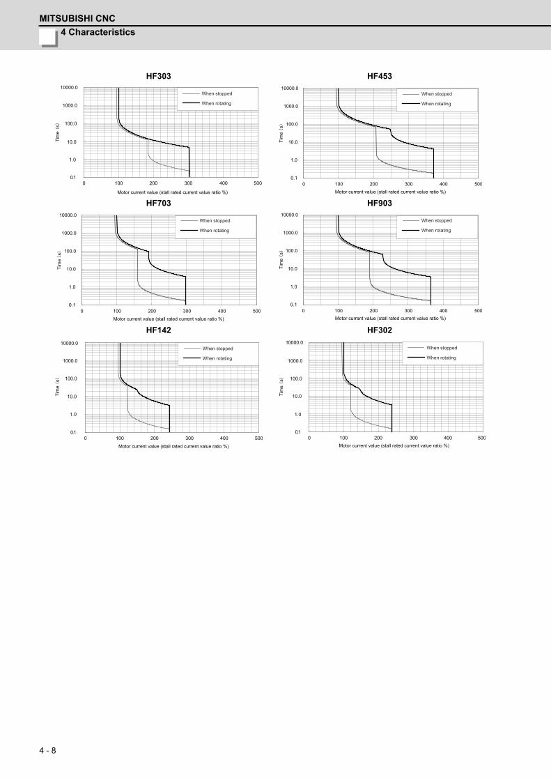
4 Characteristics
MITSUBISHI CNC
4 - 8
HF303 HF453
HF703 HF903
HF142 HF302
0.1
1.0
10.0
100.0
1000.0
10000.0
0 100 200 300 400 500
When stopped
When rotating
Motor current value (stall rated current value ratio %)
Tim
es
0.1
1.0
10.0
100.0
1000.0
10000.0
0 100 200 300 400 500
Motor current value (stall rated current value ratio %)
Tim
e s
When stopped
When rotating
0.1
1.0
10.0
100.0
1000.0
10000.0
0 100 200 300 400 500Motor current value (stall rated current value ratio %)
Tim
e s
When stopped
When rotating
0.1
1.0
10.0
100.0
1000.0
10000.0
0 100 200 300 400 500Motor current value (stall rated current value ratio %)
Tim
e s
When stopped
When rotating
0.1
1.0
10.0
100.0
1000.0
10000.0
0 100 200 300 400 500
When stopped
When rotating
Motor current value (stall rated current value ratio %)
Tim
es
0.1
1.0
10.0
100.0
1000.0
10000.0
0 100 200 300 400 500
When stopped
When rotating
Motor current value (stall rated current value ratio %)
Tim
es
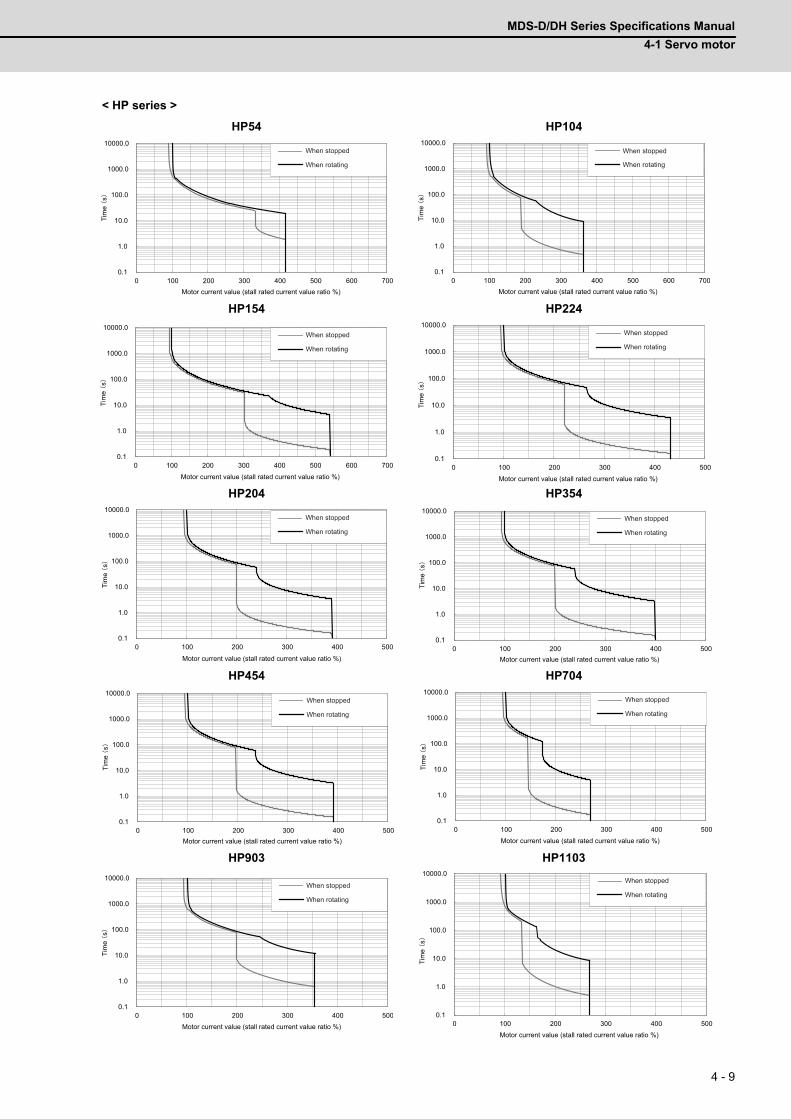
MDS-D/DH Series Specifications Manual
4-1 Servo motor
4 - 9
< HP series >
HP54 HP104
HP154 HP224
HP204 HP354
HP454 HP704
HP903 HP1103
100 200 300 400 500 600 7000.1
1.0
10.0
100.0
1000.0
10000.0
0Motor current value (stall rated current value ratio %)
Tim
e s
When stopped
When rotating
100 200 300 400 500 600 7000.1
1.0
10.0
100.0
1000.0
10000.0
0Motor current value (stall rated current value ratio %)
Tim
es
When stopped
When rotating
0.1
1.0
10.0
100.0
1000.0
10000.0
0 100 200 300 400 500 600 700Motor current value (stall rated current value ratio %)
Tim
e s
When stopped
When rotating
0.1
1.0
10.0
100.0
1000.0
10000.0
0 100 200 300 400 500Motor current value (stall rated current value ratio %)
Tim
e s
When stopped
When rotating
0.1
1.0
10.0
100.0
1000.0
10000.0
0 100 200 300 400 500
Motor current value (stall rated current value ratio %)
Tim
es
When stopped
When rotating
0.1
1.0
10.0
100.0
1000.0
10000.0
0 100 200 300 400 500Motor current value (stall rated current value ratio %)
Tim
e s
When stopped
When rotating
0.1
1.0
10.0
100.0
1000.0
10000.0
0 100 200 300 400 500Motor current value (stall rated current value ratio %)
Tim
e s
When stopped
When rotating
0.1
1.0
10.0
100.0
1000.0
10000.0
0 100 200 300 400 500Motor current value (stall rated current value ratio %)
Tim
e s
When stopped
When rotating
100 200 300 400 5000.1
1.0
10.0
100.0
1000.0
10000.0
0Motor current value (stall rated current value ratio %)
Tim
e s
When stopped
When rotating
100 200 300 400 5000.1
1.0
10.0
100.0
1000.0
10000.0
0Motor current value (stall rated current value ratio %)
Tim
e s
When stopped
When rotating
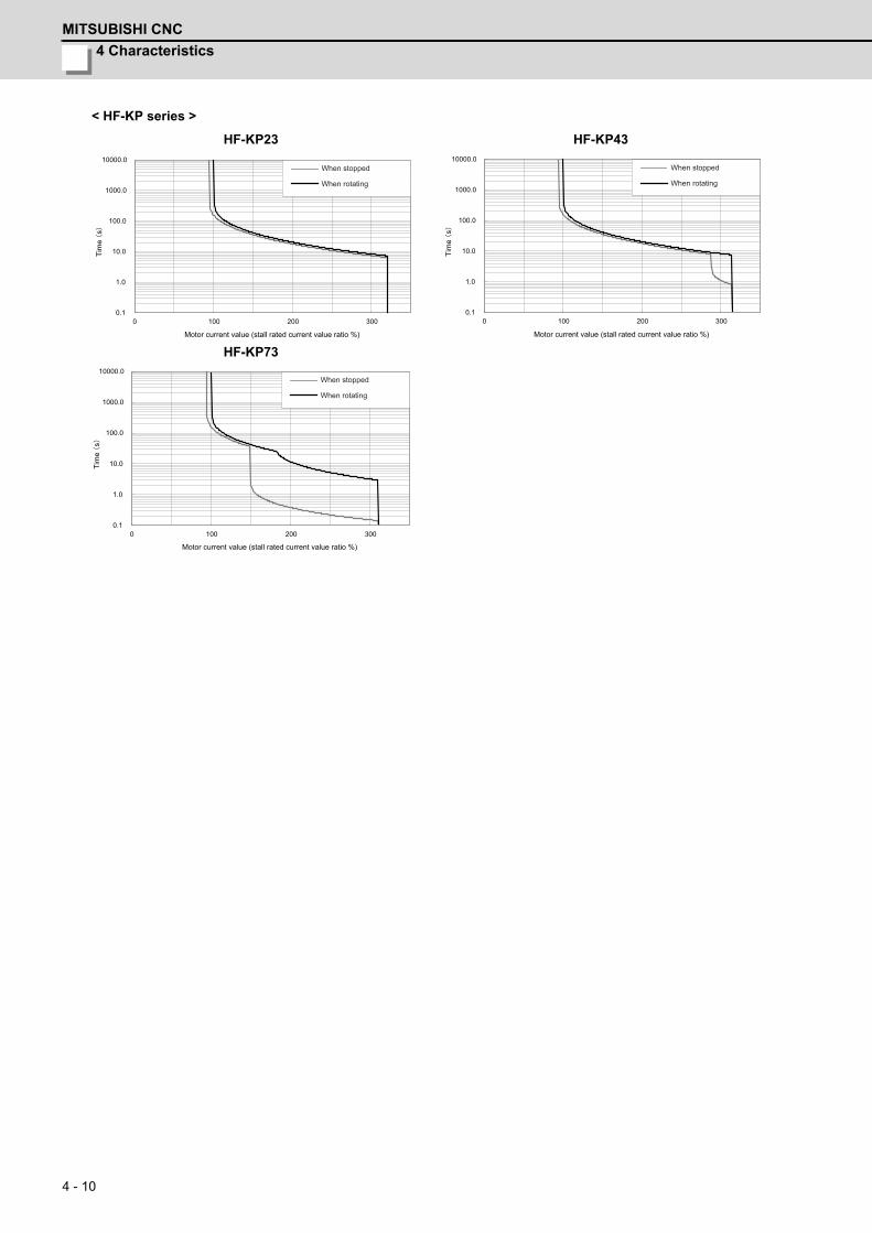
4 Characteristics
MITSUBISHI CNC
4 - 10
< HF-KP series >
HF-KP23 HF-KP43
HF-KP73
0.1
1.0
10.0
100.0
1000.0
10000.0
0 100 200 300
Motor current value (stall rated current value ratio %)
Tim
e s
When stopped
When rotating
0.1
1.0
10.0
100.0
1000.0
10000.0
0 100 200 300
Motor current value (stall rated current value ratio %)
Tim
e s
When stopped
When rotating
0.1
1.0
10.0
100.0
1000.0
10000.0
0 100 200 300
Motor current value (stall rated current value ratio %)
Tim
e s
When stopped
When rotating
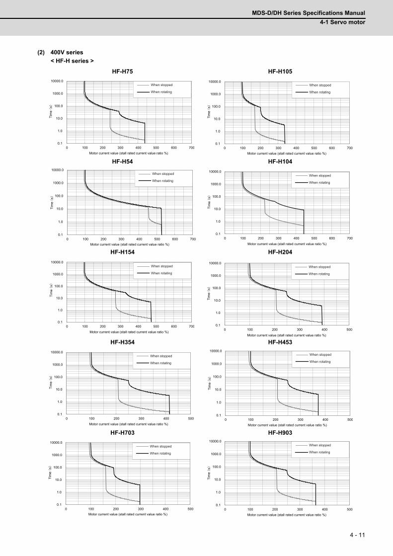
MDS-D/DH Series Specifications Manual
4-1 Servo motor
4 - 11
(2) 400V series
< HF-H series >
HF-H75 HF-H105
HF-H54 HF-H104
HF-H154 HF-H204
HF-H354 HF-H453
HF-H703 HF-H903
0.1
1.0
10.0
100.0
1000.0
10000.0
0 100 200 300 400 500 600 700Motor current value (stall rated current value ratio %)
Tim
e s
When stopped
When rotating
0.1
1.0
10.0
100.0
1000.0
10000.0
0 100 200 300 400 500 600 700Motor current value (stall rated current value ratio %)
Tim
e s
When stopped
When rotating
0.1
1.0
10.0
100.0
1000.0
10000.0
0 100 200 300 400 500 600 700Motor current value (stall rated current value ratio %)
Tim
e s
When stopped
When rotating
100 200 300 400 500 600 7000.1
1.0
10.0
100.0
1000.0
10000.0
0
Motor current value (stall rated current value ratio %)
Tim
e s
When stopped
When rotating
0.1
1.0
10.0
100.0
1000.0
10000.0
0 100 200 300 400 500 600 700Motor current value (stall rated current value ratio %)
Tim
e s
When stopped
When rotating
0.1
1.0
10.0
100.0
1000.0
10000.0
0 100 200 300 400 500
Motor current value (stall rated current value ratio %)
Tim
e s
When stopped
When rotating
0.1
1.0
10.0
100.0
1000.0
10000.0
0 100 200 300 400 500Motor current value (stall rated current value ratio %)
Tim
e s
When stopped
When rotating
0.1
1.0
10.0
100.0
1000.0
10000.0
0 100 200 300 400 500Motor current value (stall rated current value ratio %)
Tim
e s
When stopped
When rotating
0.1
1.0
10.0
100.0
1000.0
10000.0
0 100 200 300 400 500Motor current value (stall rated current value ratio %)
Tim
e s
When stopped
When rotating
0.1
1.0
10.0
100.0
1000.0
10000.0
0 100 200 300 400 500Motor current value (stall rated current value ratio %)
Tim
e s
When stopped
When rotating
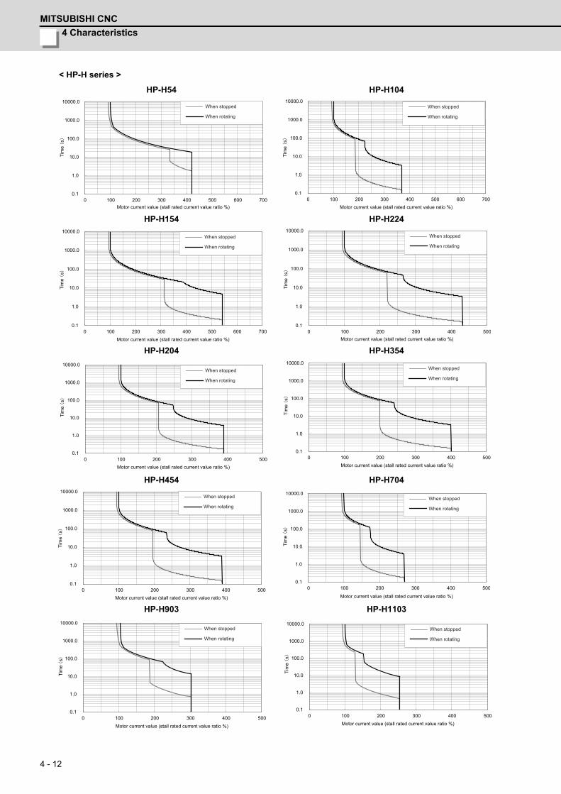
4 Characteristics
MITSUBISHI CNC
4 - 12
< HP-H series >
HP-H54 HP-H104
HP-H154 HP-H224
HP-H204 HP-H354
HP-H454 HP-H704
HP-H903 HP-H1103
100 200 300 400 500 600 7000.1
1.0
10.0
100.0
1000.0
10000.0
0Motor current value (stall rated current value ratio %)
Tim
e s
When stopped
When rotating
0.1
1.0
10.0
100.0
1000.0
10000.0
0 100 200 300 400 500 600 700Motor current value (stall rated current value ratio %)
Tim
e s
When stopped
When rotating
0.1
1.0
10.0
100.0
1000.0
10000.0
0 100 200 300 400 500 600 700Motor current value (stall rated current value ratio %)
Tim
e s
When stopped
When rotating
0.1
1.0
10.0
100.0
1000.0
10000.0
0 100 200 300 400 500Motor current value (stall rated current value ratio %)
Tim
e s
When stopped
When rotating
0.1
1.0
10.0
100.0
1000.0
10000.0
0 100 200 300 400 500Motor current value (stall rated current value ratio %)
Tim
e s
When stopped
When rotating
0.1
1.0
10.0
100.0
1000.0
10000.0
0 100 200 300 400 500Motor current value (stall rated current value ratio %)
Tim
e s
When stopped
When rotating
0.1
1.0
10.0
100.0
1000.0
10000.0
0 100 200 300 400 500Motor current value (stall rated current value ratio %)
Tim
e s
When stopped
When rotating
0.1
1.0
10.0
100.0
1000.0
10000.0
0 100 200 300 400 500
Motor current value (stall rated current value ratio %)
Tim
e s
When stopped
When rotating
100 200 300 400 5000.1
1.0
10.0
100.0
1000.0
10000.0
0Motor current value (stall rated current value ratio %)
Tim
e s
When stopped
When rotating
100 200 300 400 5000.1
1.0
10.0
100.0
1000.0
10000.0
0Motor current value (stall rated current value ratio %)
Tim
e s
When stopped
When rotating
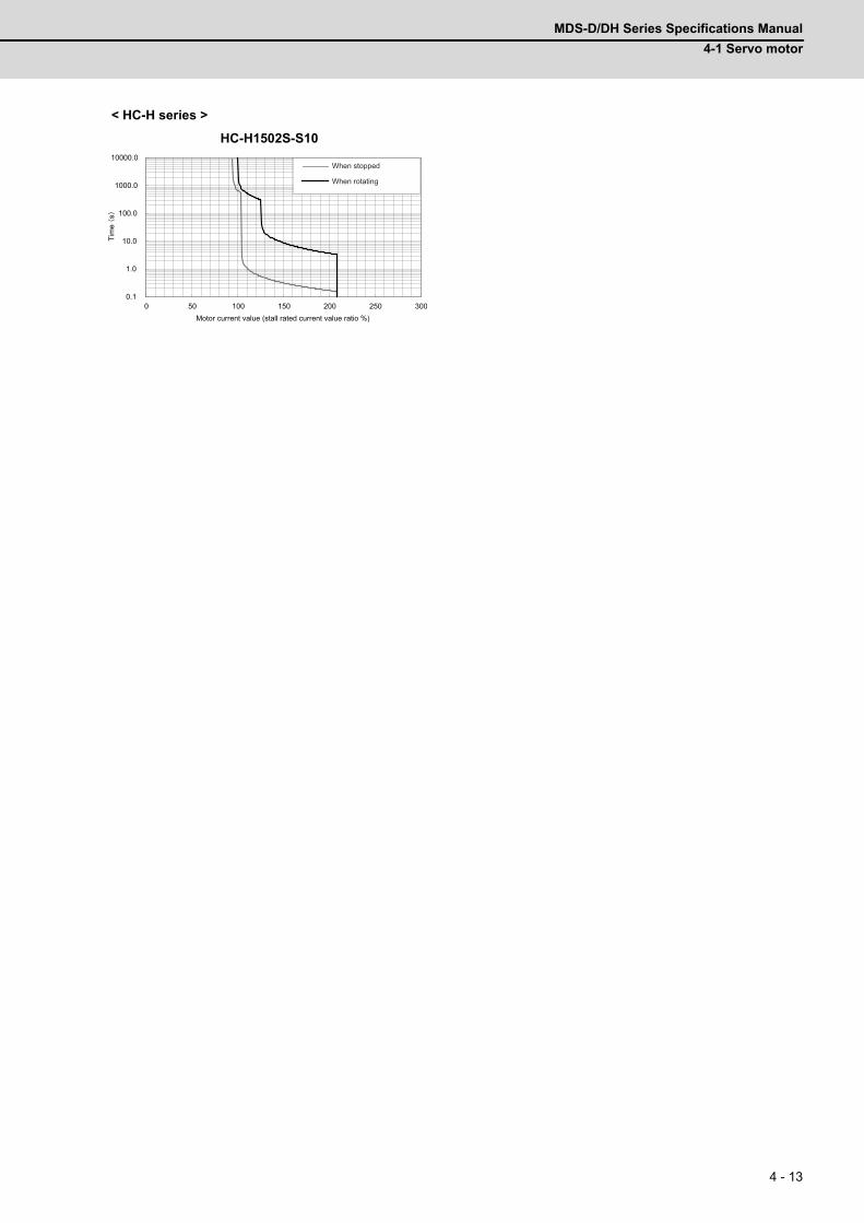
MDS-D/DH Series Specifications Manual
4-1 Servo motor
4 - 13
< HC-H series >
HC-H1502S-S10
0.1
1.0
10.0
100.0
1000.0
10000.0
0 50 100 150 200 250 300Motor current value (stall rated current value ratio %)
Tim
e s
When stopped
When rotating
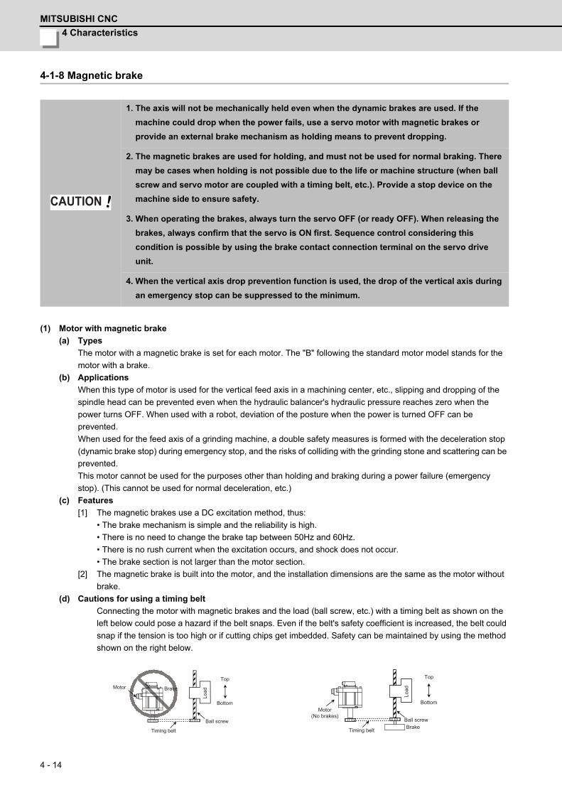
4 Characteristics
MITSUBISHI CNC
4 - 14
4-1-8 Magnetic brake
(1) Motor with magnetic brake
(a) Types
The motor with a magnetic brake is set for each motor. The "B" following the standard motor model stands for the
motor with a brake.
(b) Applications
When this type of motor is used for the vertical feed axis in a machining center, etc., slipping and dropping of the
spindle head can be prevented even when the hydraulic balancer's hydraulic pressure reaches zero when the
power turns OFF. When used with a robot, deviation of the posture when the power is turned OFF can be
prevented.
When used for the feed axis of a grinding machine, a double safety measures is formed with the deceleration stop
(dynamic brake stop) during emergency stop, and the risks of colliding with the grinding stone and scattering can be
prevented.
This motor cannot be used for the purposes other than holding and braking during a power failure (emergency
stop). (This cannot be used for normal deceleration, etc.)
(c) Features
[1] The magnetic brakes use a DC excitation method, thus:
• The brake mechanism is simple and the reliability is high.
• There is no need to change the brake tap between 50Hz and 60Hz.
• There is no rush current when the excitation occurs, and shock does not occur.
• The brake section is not larger than the motor section.
[2] The magnetic brake is built into the motor, and the installation dimensions are the same as the motor without
brake.
(d) Cautions for using a timing belt
Connecting the motor with magnetic brakes and the load (ball screw, etc.) with a timing belt as shown on the
left below could pose a hazard if the belt snaps. Even if the belt's safety coefficient is increased, the belt could
snap if the tension is too high or if cutting chips get imbedded. Safety can be maintained by using the method
shown on the right below.
1. The axis will not be mechanically held even when the dynamic brakes are used. If the
machine could drop when the power fails, use a servo motor with magnetic brakes or
provide an external brake mechanism as holding means to prevent dropping.
2. The magnetic brakes are used for holding, and must not be used for normal braking. There
may be cases when holding is not possible due to the life or machine structure (when ball
screw and servo motor are coupled with a timing belt, etc.). Provide a stop device on the
machine side to ensure safety.
3. When operating the brakes, always turn the servo OFF (or ready OFF). When releasing the
brakes, always confirm that the servo is ON first. Sequence control considering this
condition is possible by using the brake contact connection terminal on the servo drive
unit.
4. When the vertical axis drop prevention function is used, the drop of the vertical axis during
an emergency stop can be suppressed to the minimum.
CAUTION
Motor
Timing belt
Ball screw
Brake
Top
Bottom
Load
Motor(No brakes)
Timing belt
Ball screw
Top
Bottom
Load
Brake
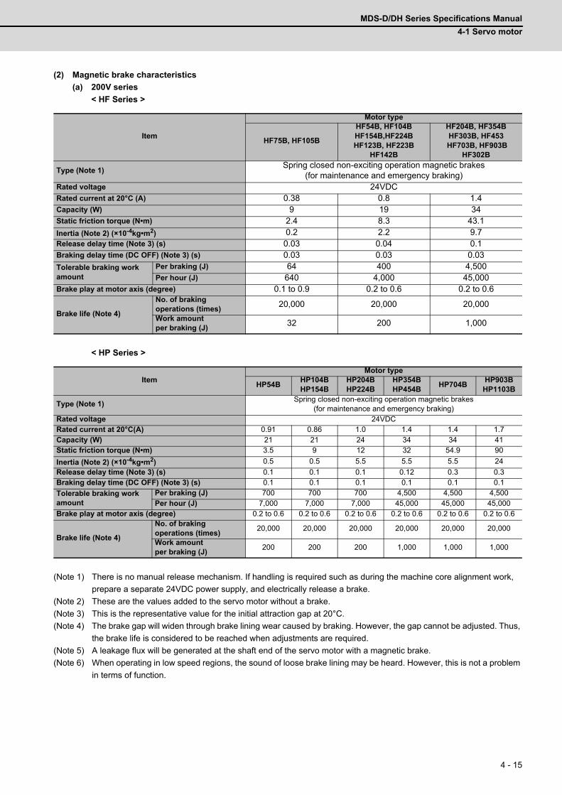
MDS-D/DH Series Specifications Manual
4-1 Servo motor
4 - 15
(2) Magnetic brake characteristics
(a) 200V series
< HF Series >
< HP Series >
(Note 1) There is no manual release mechanism. If handling is required such as during the machine core alignment work,
prepare a separate 24VDC power supply, and electrically release a brake.
(Note 2) These are the values added to the servo motor without a brake.
(Note 3) This is the representative value for the initial attraction gap at 20°C.
(Note 4) The brake gap will widen through brake lining wear caused by braking. However, the gap cannot be adjusted. Thus,
the brake life is considered to be reached when adjustments are required.
(Note 5) A leakage flux will be generated at the shaft end of the servo motor with a magnetic brake.
(Note 6) When operating in low speed regions, the sound of loose brake lining may be heard. However, this is not a problem
in terms of function.
Item
Motor type
HF75B, HF105B
HF54B, HF104BHF154B,HF224BHF123B, HF223B
HF142B
HF204B, HF354BHF303B, HF453
HF703B, HF903BHF302B
Type (Note 1)Spring closed non-exciting operation magnetic brakes
(for maintenance and emergency braking)Rated voltage 24VDCRated current at 20°C (A) 0.38 0.8 1.4Capacity (W) 9 19 34Static friction torque (N•m) 2.4 8.3 43.1
Inertia (Note 2) (×10-4kg•m2) 0.2 2.2 9.7Release delay time (Note 3) (s) 0.03 0.04 0.1Braking delay time (DC OFF) (Note 3) (s) 0.03 0.03 0.03
Tolerable braking work amount
Per braking (J) 64 400 4,500Per hour (J) 640 4,000 45,000
Brake play at motor axis (degree) 0.1 to 0.9 0.2 to 0.6 0.2 to 0.6
Brake life (Note 4)
No. of braking operations (times)
20,000 20,000 20,000
Work amount per braking (J)
32 200 1,000
ItemMotor type
HP54BHP104BHP154B
HP204BHP224B
HP354BHP454B
HP704BHP903B
HP1103B
Type (Note 1)Spring closed non-exciting operation magnetic brakes
(for maintenance and emergency braking)Rated voltage 24VDCRated current at 20°C(A) 0.91 0.86 1.0 1.4 1.4 1.7Capacity (W) 21 21 24 34 34 41Static friction torque (N•m) 3.5 9 12 32 54.9 90
Inertia (Note 2) (×10-4kg•m2) 0.5 0.5 5.5 5.5 5.5 24
Release delay time (Note 3) (s) 0.1 0.1 0.1 0.12 0.3 0.3Braking delay time (DC OFF) (Note 3) (s) 0.1 0.1 0.1 0.1 0.1 0.1
Tolerable braking work amount
Per braking (J) 700 700 700 4,500 4,500 4,500Per hour (J) 7,000 7,000 7,000 45,000 45,000 45,000
Brake play at motor axis (degree) 0.2 to 0.6 0.2 to 0.6 0.2 to 0.6 0.2 to 0.6 0.2 to 0.6 0.2 to 0.6
Brake life (Note 4)
No. of braking operations (times)
20,000 20,000 20,000 20,000 20,000 20,000
Work amount per braking (J)
200 200 200 1,000 1,000 1,000
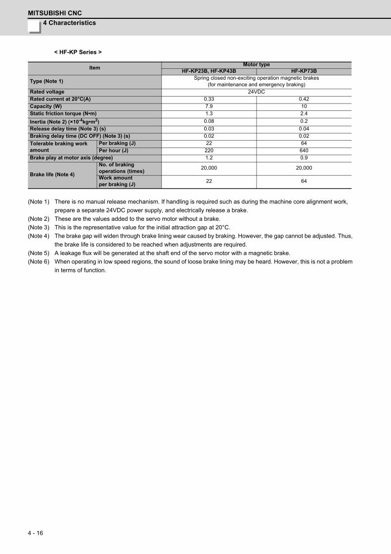
4 Characteristics
MITSUBISHI CNC
4 - 16
< HF-KP Series >
(Note 1) There is no manual release mechanism. If handling is required such as during the machine core alignment work,
prepare a separate 24VDC power supply, and electrically release a brake.
(Note 2) These are the values added to the servo motor without a brake.
(Note 3) This is the representative value for the initial attraction gap at 20°C.
(Note 4) The brake gap will widen through brake lining wear caused by braking. However, the gap cannot be adjusted. Thus,
the brake life is considered to be reached when adjustments are required.
(Note 5) A leakage flux will be generated at the shaft end of the servo motor with a magnetic brake.
(Note 6) When operating in low speed regions, the sound of loose brake lining may be heard. However, this is not a problem
in terms of function.
ItemMotor type
HF-KP23B, HF-KP43B HF-KP73B
Type (Note 1)Spring closed non-exciting operation magnetic brakes
(for maintenance and emergency braking)Rated voltage 24VDCRated current at 20°C(A) 0.33 0.42Capacity (W) 7.9 10Static friction torque (N•m) 1.3 2.4
Inertia (Note 2) (×10-4kg•m2) 0.08 0.2
Release delay time (Note 3) (s) 0.03 0.04Braking delay time (DC OFF) (Note 3) (s) 0.02 0.02
Tolerable braking work amount
Per braking (J) 22 64Per hour (J) 220 640
Brake play at motor axis (degree) 1.2 0.9
Brake life (Note 4)
No. of braking operations (times)
20,000 20,000
Work amount per braking (J)
22 64
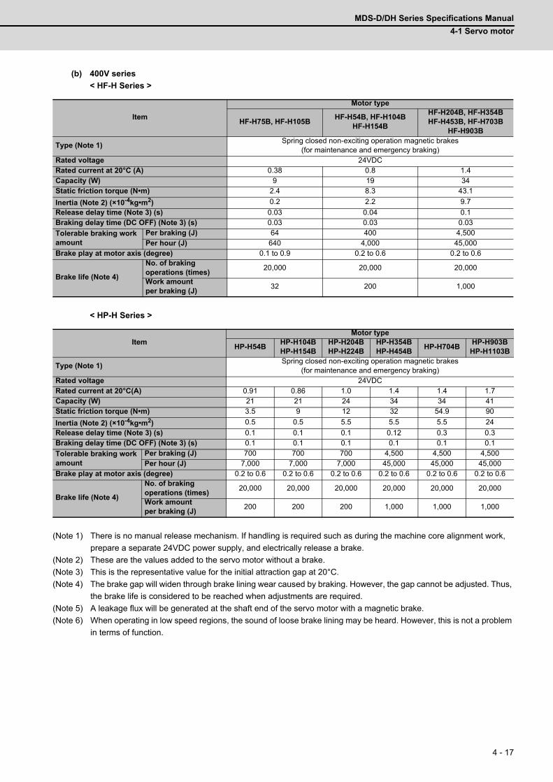
MDS-D/DH Series Specifications Manual
4-1 Servo motor
4 - 17
(b) 400V series
< HF-H Series >
< HP-H Series >
(Note 1) There is no manual release mechanism. If handling is required such as during the machine core alignment work,
prepare a separate 24VDC power supply, and electrically release a brake.
(Note 2) These are the values added to the servo motor without a brake.
(Note 3) This is the representative value for the initial attraction gap at 20°C.
(Note 4) The brake gap will widen through brake lining wear caused by braking. However, the gap cannot be adjusted. Thus,
the brake life is considered to be reached when adjustments are required.
(Note 5) A leakage flux will be generated at the shaft end of the servo motor with a magnetic brake.
(Note 6) When operating in low speed regions, the sound of loose brake lining may be heard. However, this is not a problem
in terms of function.
Item
Motor type
HF-H75B, HF-H105BHF-H54B, HF-H104B
HF-H154B
HF-H204B, HF-H354BHF-H453B, HF-H703B
HF-H903B
Type (Note 1)Spring closed non-exciting operation magnetic brakes
(for maintenance and emergency braking)Rated voltage 24VDCRated current at 20°C (A) 0.38 0.8 1.4Capacity (W) 9 19 34Static friction torque (N•m) 2.4 8.3 43.1
Inertia (Note 2) (×10-4kg•m2) 0.2 2.2 9.7
Release delay time (Note 3) (s) 0.03 0.04 0.1Braking delay time (DC OFF) (Note 3) (s) 0.03 0.03 0.03
Tolerable braking work amount
Per braking (J) 64 400 4,500Per hour (J) 640 4,000 45,000
Brake play at motor axis (degree) 0.1 to 0.9 0.2 to 0.6 0.2 to 0.6
Brake life (Note 4)
No. of braking operations (times)
20,000 20,000 20,000
Work amount per braking (J)
32 200 1,000
ItemMotor type
HP-H54BHP-H104BHP-H154B
HP-H204BHP-H224B
HP-H354BHP-H454B
HP-H704BHP-H903B
HP-H1103B
Type (Note 1)Spring closed non-exciting operation magnetic brakes
(for maintenance and emergency braking)Rated voltage 24VDCRated current at 20°C(A) 0.91 0.86 1.0 1.4 1.4 1.7Capacity (W) 21 21 24 34 34 41Static friction torque (N•m) 3.5 9 12 32 54.9 90
Inertia (Note 2) (×10-4kg•m2) 0.5 0.5 5.5 5.5 5.5 24
Release delay time (Note 3) (s) 0.1 0.1 0.1 0.12 0.3 0.3Braking delay time (DC OFF) (Note 3) (s) 0.1 0.1 0.1 0.1 0.1 0.1
Tolerable braking work amount
Per braking (J) 700 700 700 4,500 4,500 4,500Per hour (J) 7,000 7,000 7,000 45,000 45,000 45,000
Brake play at motor axis (degree) 0.2 to 0.6 0.2 to 0.6 0.2 to 0.6 0.2 to 0.6 0.2 to 0.6 0.2 to 0.6
Brake life (Note 4)
No. of braking operations (times)
20,000 20,000 20,000 20,000 20,000 20,000
Work amount per braking (J)
200 200 200 1,000 1,000 1,000
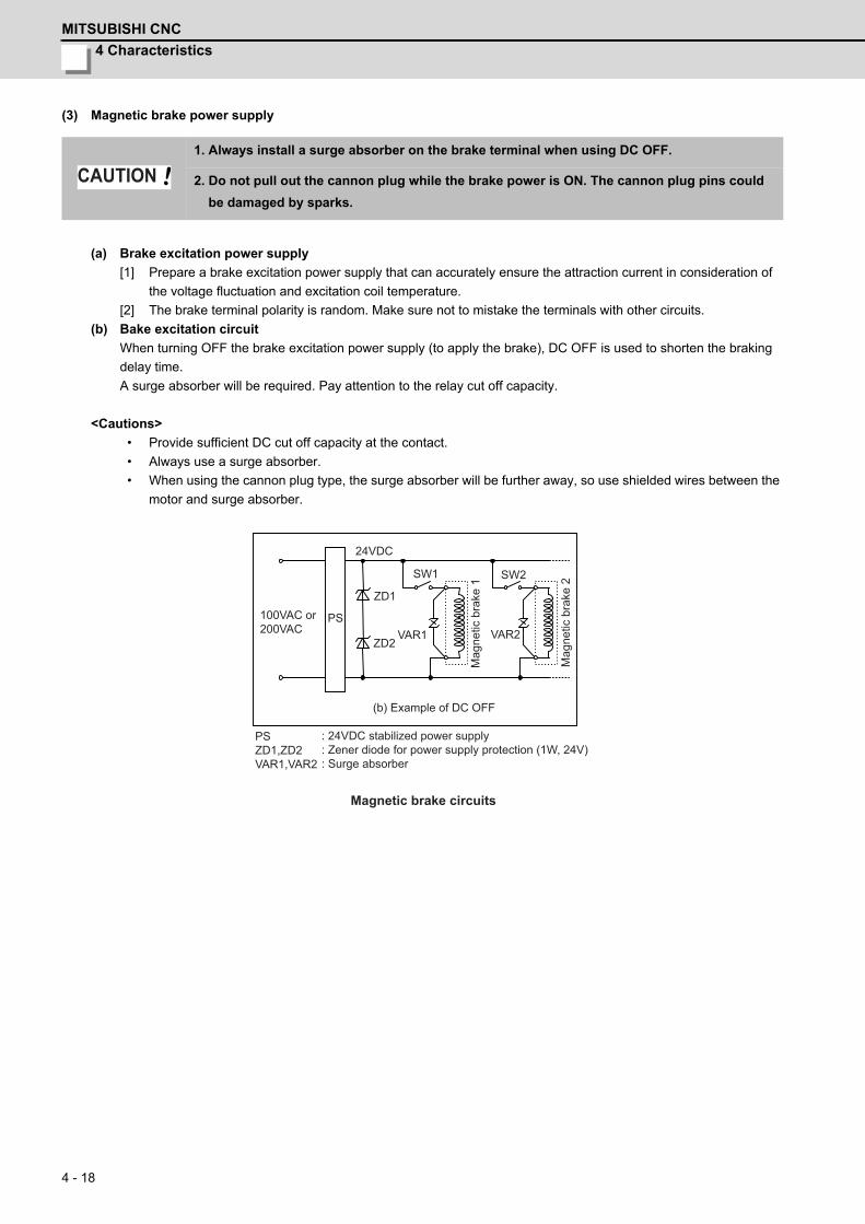
4 Characteristics
MITSUBISHI CNC
4 - 18
(3) Magnetic brake power supply
(a) Brake excitation power supply
[1] Prepare a brake excitation power supply that can accurately ensure the attraction current in consideration of
the voltage fluctuation and excitation coil temperature.
[2] The brake terminal polarity is random. Make sure not to mistake the terminals with other circuits.
(b) Bake excitation circuit
When turning OFF the brake excitation power supply (to apply the brake), DC OFF is used to shorten the braking
delay time.
A surge absorber will be required. Pay attention to the relay cut off capacity.
<Cautions>
• Provide sufficient DC cut off capacity at the contact.
• Always use a surge absorber.
• When using the cannon plug type, the surge absorber will be further away, so use shielded wires between the
motor and surge absorber.
1. Always install a surge absorber on the brake terminal when using DC OFF.
2. Do not pull out the cannon plug while the brake power is ON. The cannon plug pins could
be damaged by sparks.
CAUTION
SW1 SW2
VAR1
ZD1
ZD2VAR2
PS
24VDC
100VAC or200VAC
(b) Example of DC OFF
PSZD1,ZD2VAR1,VAR2
Magnetic brake circuits
Mag
netic
bra
ke 1
Mag
netic
bra
ke 2
: 24VDC stabilized power supply: Zener diode for power supply protection (1W, 24V): Surge absorber
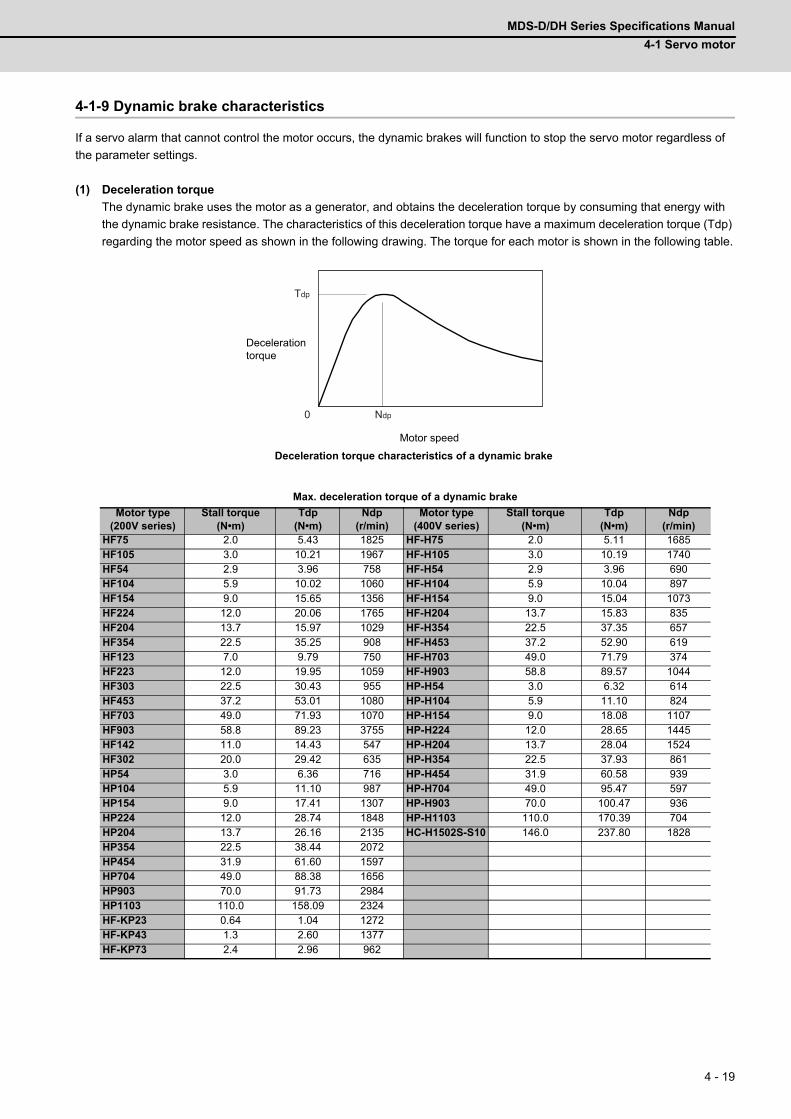
MDS-D/DH Series Specifications Manual
4-1 Servo motor
4 - 19
4-1-9 Dynamic brake characteristics
If a servo alarm that cannot control the motor occurs, the dynamic brakes will function to stop the servo motor regardless of
the parameter settings.
(1) Deceleration torque
The dynamic brake uses the motor as a generator, and obtains the deceleration torque by consuming that energy with
the dynamic brake resistance. The characteristics of this deceleration torque have a maximum deceleration torque (Tdp)
regarding the motor speed as shown in the following drawing. The torque for each motor is shown in the following table.
Max. deceleration torque of a dynamic brake
Motor type(200V series)
Stall torque(N•m)
Tdp(N•m)
Ndp(r/min)
Motor type(400V series)
Stall torque(N•m)
Tdp(N•m)
Ndp(r/min)
HF75 2.0 5.43 1825 HF-H75 2.0 5.11 1685HF105 3.0 10.21 1967 HF-H105 3.0 10.19 1740HF54 2.9 3.96 758 HF-H54 2.9 3.96 690HF104 5.9 10.02 1060 HF-H104 5.9 10.04 897HF154 9.0 15.65 1356 HF-H154 9.0 15.04 1073HF224 12.0 20.06 1765 HF-H204 13.7 15.83 835HF204 13.7 15.97 1029 HF-H354 22.5 37.35 657HF354 22.5 35.25 908 HF-H453 37.2 52.90 619HF123 7.0 9.79 750 HF-H703 49.0 71.79 374HF223 12.0 19.95 1059 HF-H903 58.8 89.57 1044HF303 22.5 30.43 955 HP-H54 3.0 6.32 614HF453 37.2 53.01 1080 HP-H104 5.9 11.10 824HF703 49.0 71.93 1070 HP-H154 9.0 18.08 1107HF903 58.8 89.23 3755 HP-H224 12.0 28.65 1445HF142 11.0 14.43 547 HP-H204 13.7 28.04 1524HF302 20.0 29.42 635 HP-H354 22.5 37.93 861HP54 3.0 6.36 716 HP-H454 31.9 60.58 939HP104 5.9 11.10 987 HP-H704 49.0 95.47 597HP154 9.0 17.41 1307 HP-H903 70.0 100.47 936HP224 12.0 28.74 1848 HP-H1103 110.0 170.39 704HP204 13.7 26.16 2135 HC-H1502S-S10 146.0 237.80 1828HP354 22.5 38.44 2072HP454 31.9 61.60 1597HP704 49.0 88.38 1656HP903 70.0 91.73 2984HP1103 110.0 158.09 2324HF-KP23 0.64 1.04 1272HF-KP43 1.3 2.60 1377HF-KP73 2.4 2.96 962
Tdp
Ndp0
Motor speed
Decelerationtorque
Deceleration torque characteristics of a dynamic brake
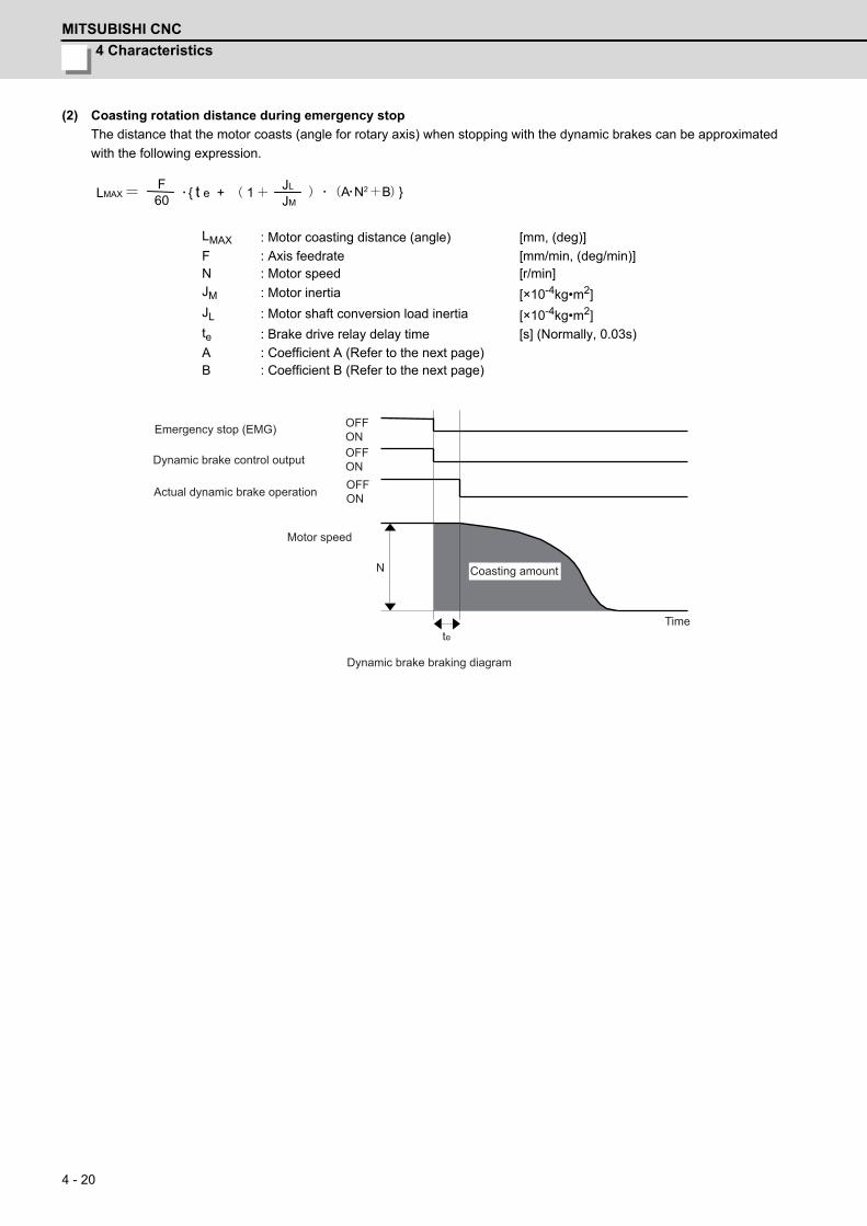
4 Characteristics
MITSUBISHI CNC
4 - 20
(2) Coasting rotation distance during emergency stop
The distance that the motor coasts (angle for rotary axis) when stopping with the dynamic brakes can be approximated
with the following expression.
LMAX : Motor coasting distance (angle) [mm, (deg)]
F : Axis feedrate [mm/min, (deg/min)]N : Motor speed [r/min]JM : Motor inertia [×10-4kg•m2]JL : Motor shaft conversion load inertia [×10-4kg•m2]te : Brake drive relay delay time [s] (Normally, 0.03s)
A : Coefficient A (Refer to the next page)B : Coefficient B (Refer to the next page)
JM JL
LMAX 60 F
t e + 1 A N2 B
N
Dynamic brake braking diagram
Motor speed
Actual dynamic brake operation
Dynamic brake control output
Emergency stop (EMG) OFFONOFFONOFFON
teTime
Coasting amount
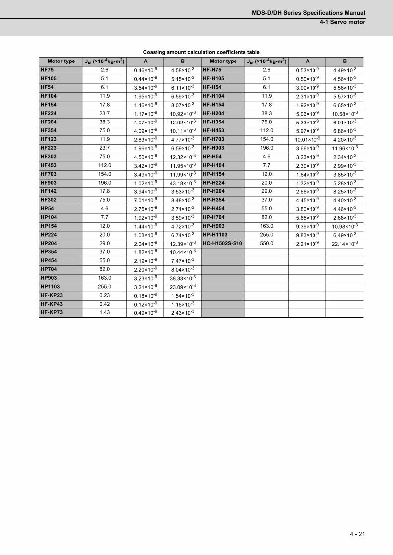
MDS-D/DH Series Specifications Manual
4-1 Servo motor
4 - 21
Coasting amount calculation coefficients table
Motor type JM (×10-4kg•m2) A B Motor type JM (×10-4kg•m2) A B
HF75 2.6 0.46×10⁻⁹ 4.58×10⁻³ HF-H75 2.6 0.53×10⁻⁹ 4.49×10⁻³
HF105 5.1 0.44×10⁻⁹ 5.15×10⁻³ HF-H105 5.1 0.50×10⁻⁹ 4.56×10⁻³
HF54 6.1 3.54×10⁻⁹ 6.11×10⁻³ HF-H54 6.1 3.90×10⁻⁹ 5.56×10⁻³
HF104 11.9 1.95×10⁻⁹ 6.59×10⁻³ HF-H104 11.9 2.31×10⁻⁹ 5.57×10⁻³
HF154 17.8 1.46×10⁻⁹ 8.07×10⁻³ HF-H154 17.8 1.92×10⁻⁹ 6.65×10⁻³
HF224 23.7 1.17×10⁻⁹ 10.92×10⁻³ HF-H204 38.3 5.06×10⁻⁹ 10.58×10⁻³
HF204 38.3 4.07×10⁻⁹ 12.92×10⁻³ HF-H354 75.0 5.33×10⁻⁹ 6.91×10⁻³
HF354 75.0 4.09×10⁻⁹ 10.11×10⁻³ HF-H453 112.0 5.97×10⁻⁹ 6.86×10⁻³
HF123 11.9 2.83×10⁻⁹ 4.77×10⁻³ HF-H703 154.0 10.01×10⁻⁹ 4.20×10⁻³
HF223 23.7 1.96×10⁻⁹ 6.59×10⁻³ HF-H903 196.0 3.66×10⁻⁹ 11.96×10⁻³
HF303 75.0 4.50×10⁻⁹ 12.32×10⁻³ HP-H54 4.6 3.23×10⁻⁹ 2.34×10⁻³
HF453 112.0 3.42×10⁻⁹ 11.95×10⁻³ HP-H104 7.7 2.30×10⁻⁹ 2.99×10⁻³
HF703 154.0 3.49×10⁻⁹ 11.99×10⁻³ HP-H154 12.0 1.64×10⁻⁹ 3.85×10⁻³
HF903 196.0 1.02×10⁻⁹ 43.18×10⁻³ HP-H224 20.0 1.32×10⁻⁹ 5.28×10⁻³
HF142 17.8 3.94×10⁻⁹ 3.53×10⁻³ HP-H204 29.0 2.66×10⁻⁹ 8.25×10⁻³
HF302 75.0 7.01×10⁻⁹ 8.48×10⁻³ HP-H354 37.0 4.45×10⁻⁹ 4.40×10⁻³
HP54 4.6 2.75×10⁻⁹ 2.71×10⁻³ HP-H454 55.0 3.80×10⁻⁹ 4.46×10⁻³
HP104 7.7 1.92×10⁻⁹ 3.59×10⁻³ HP-H704 82.0 5.65×10⁻⁹ 2.68×10⁻³
HP154 12.0 1.44×10⁻⁹ 4.72×10⁻³ HP-H903 163.0 9.39×10⁻⁹ 10.98×10⁻³
HP224 20.0 1.03×10⁻⁹ 6.74×10⁻³ HP-H1103 255.0 9.83×10⁻⁹ 6.49×10⁻³
HP204 29.0 2.04×10⁻⁹ 12.39×10⁻³ HC-H1502S-S10 550.0 2.21×10⁻⁹ 22.14×10⁻³
HP354 37.0 1.82×10⁻⁹ 10.44×10⁻³
HP454 55.0 2.19×10⁻⁹ 7.47×10⁻³
HP704 82.0 2.20×10⁻⁹ 8.04×10⁻³
HP903 163.0 3.23×10⁻⁹ 38.33×10⁻³
HP1103 255.0 3.21×10⁻⁹ 23.09×10⁻³
HF-KP23 0.23 0.18×10⁻⁹ 1.54×10⁻³
HF-KP43 0.42 0.12×10⁻⁹ 1.16×10⁻³
HF-KP73 1.43 0.49×10⁻⁹ 2.43×10⁻³

4 Characteristics
MITSUBISHI CNC
4 - 22
4-2 Spindle motor4-2-1 Environmental conditions
4-2-2 Shaft characteristics
There is a limit to the load that can be applied on the motor shaft. Make sure that the load applied on the radial direction,
when mounted on the machine, is below the tolerable values given below. These loads may affect the motor output
torque, so consider them when designing the machine.
Environment ConditionsAmbient temperature 0°C to +40°C (with no freezing)Ambient humidity 90% RH or less (with no dew condensation)Storage temperature -20°C to +65°C(with no freezing)Storage humidity 90% RH or less (with no dew condensation)
AtmosphereIndoors (no direct sunlight);
no corrosive gas, inflammable gas, oil mist or dust
AltitudeOperation/storage: 1000m or less above sea levelTransportation: 10000m or less above sea level
Series Spindle motor Tolerable radial load
200Vseries
SJ-VL2.2ZT, SJ-V3.7-02ZT 196N
SJ-VL11-10FZT 245N
SJ-VL0.75-01T, SJ-VL1.5-01T 490N
SJ-D3.7/100-01, SJ-DJ5.5/100-01,SJ-V2.2-01T, SJ-V3.7-01T, SJ-V5.5-01ZT, SJ-V7.5-01ZT, SJ-V7.5-03ZT,SJ-V11-06ZT, SJ-VL11-05FZT-S01, SJ-VL11-07ZT
980N
SJ-D5.5/100-01, SJ-DJ7.5/100-01, SJ-V11-08ZT 1470N
SJ-D7.5/100-01, SJ-D11/80-01, SJ-DJ11/100-01, SJ-DJ15/80-01SJ-V11-01T, SJ-V11-01ZT, J-V11-13ZT, SJ-V22-06ZT, SJ-V30-02ZT
1960N
SJ-V11-09T, SJ-V15-01ZT, SJ-V15-03ZT, SJ-V15-09ZT, SJ-V18.5-03T,SJ-V18.5-01ZT, SJ-V18.5-04ZT, SJ-V22-05T, SJ-V22-01ZT, SJ-V22-04ZT,SJ-V26-01ZT
2940N
SJ-V37-01T, SJ-V45-01T, SJ-V22-09T, SJ-VK22-19ZT 3920N
SJ-V55-01T 5880N
400Vseries
SJ-4-V3.7-05ZT 490N
SJ-4-V2.2-03T, SJ-4-V3.7-03T, SJ-4-V7.5-13ZT, SJ-4-V11-22ZT 980N
SJ-4-V5.5-07T, SJ-4-V11-23ZT 1470N
SJ-4-V7.5-12T, SJ-4-V11-18T, SJ-4-V30-15ZT 1960N
SJ-4-V11-21T, SJ-4-V15-18T, SJ-4-V15-20T, SJ-4-V18.5-14T, SJ-4-V18.5-17T,SJ-4-V22-15T, SJ-4-V22-16T, SJ-4-V22-18ZT, SJ-4-V26-08T
2940N
SJ-4-V37-04ZT, SJ-4-V45-02T 3920N
SJ-4-V55-03T 5880N
Consider on the machine side so that the thrust loads are not applied to the spindle motor.
Radial load
(Note) The load point is at the one-half of the shaft length.
CAUTION

MDS-D/DH Series Specifications Manual
4-2 Spindle motor
4 - 23
4-2-3 Machine accuracy
Machine accuracy of the spindle motor's output shaft and around the installation part is as below.
(Excluding special products)
4-2-4 Installation of spindle motor
Make sure that the spindle motor is installed so that the motor shaft points from downward to 90° as shown below. When
installing upward more than 90°, contact your Mitsubishi Electric dealer.
The spindle motor whose motor power line and detection lead wires are connected with connectors, as a standard,
should be installed with the connectors facing down. Installation in the standard direction is effective against dripping.
Measure to prevent oil and water must be taken when not installing in the standard direction.
To yield good cooling performance, provide a space of at least 30mm
between the cooling fan and wall. If the motor is covered by a structure and
the air is not exchanged, its cooling performance degrades and the motor is
unable to fully exercise its performance, which may cause the spindle motor
overheat alarm. Do not use the spindle motor in an enclosed space with little
ventilation.
Accuracy [mm]Measurement
pointFlange size [mm]
Amplitude of the flange surface to the output shaft a 0.08Amplitude of the flange surface's fitting outer diameter b 0.04Amplitude of the output shaft end c 0.02
1. Rubber packing for waterproof is attached on the inner surface of the top cover of terminal
block. After checking that the packing is installed, install the top cover.
2. When installing a motor on a flange, chamfer(C1) the part of flange that touches inside low
part of the motor.
a cb
Standard installation directionfor connector connection type
Down
Up
CAUTION
wall
Cooling fan
30mm or more
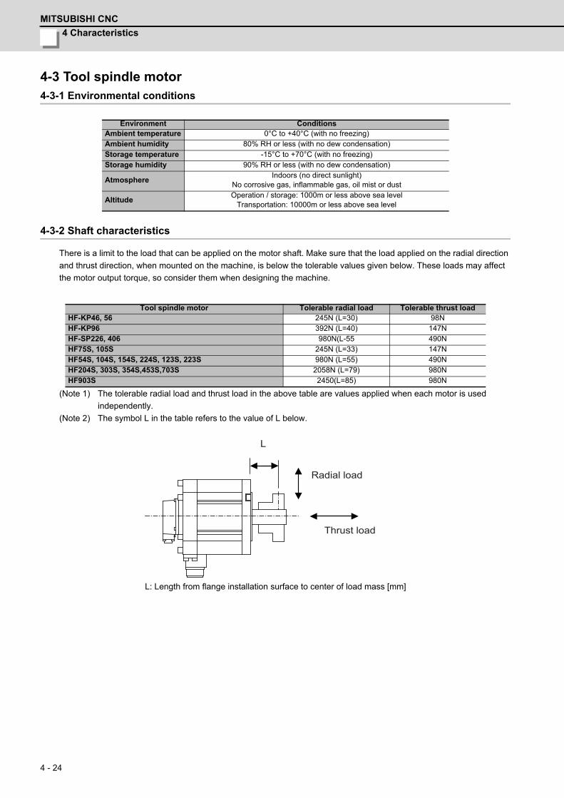
4 Characteristics
MITSUBISHI CNC
4 - 24
4-3 Tool spindle motor4-3-1 Environmental conditions
4-3-2 Shaft characteristics
There is a limit to the load that can be applied on the motor shaft. Make sure that the load applied on the radial direction
and thrust direction, when mounted on the machine, is below the tolerable values given below. These loads may affect
the motor output torque, so consider them when designing the machine.
(Note 1) The tolerable radial load and thrust load in the above table are values applied when each motor is used
independently.
(Note 2) The symbol L in the table refers to the value of L below.
L: Length from flange installation surface to center of load mass [mm]
Environment ConditionsAmbient temperature 0°C to +40°C (with no freezing)Ambient humidity 80% RH or less (with no dew condensation)Storage temperature -15°C to +70°C (with no freezing)Storage humidity 90% RH or less (with no dew condensation)
AtmosphereIndoors (no direct sunlight)
No corrosive gas, inflammable gas, oil mist or dust
AltitudeOperation / storage: 1000m or less above sea level
Transportation: 10000m or less above sea level
Tool spindle motor Tolerable radial load Tolerable thrust loadHF-KP46, 56 245N (L=30) 98NHF-KP96 392N (L=40) 147NHF-SP226, 406 980N(L-55 490NHF75S, 105S 245N (L=33) 147NHF54S, 104S, 154S, 224S, 123S, 223S 980N (L=55) 490NHF204S, 303S, 354S,453S,703S 2058N (L=79) 980NHF903S 2450(L=85) 980N
Radial load
Thrust load
L
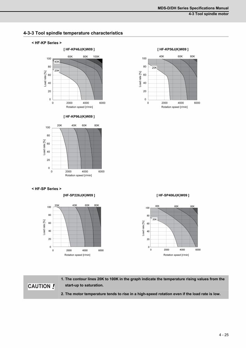
MDS-D/DH Series Specifications Manual
4-3 Tool spindle motor
4 - 25
4-3-3 Tool spindle temperature characteristics
< HF-KP Series >
< HF-SP Series >
[ HF-KP46J(K)W09 ] [ HF-KP56J(K)W09 ]
[ HF-KP96J(K)W09 ]
[HF-SP226J(K)W09 ] [ HF-SP406J(K)W09 ]
1. The contour lines 20K to 100K in the graph indicate the temperature rising values from the
start-up to saturation.
2. The motor temperature tends to rise in a high-speed rotation even if the load rate is low.
0
20
40
60
80
100
0 2000 4000 6000
60K 80K 100K
40K
20K
Rotation speed [r/min]
Load
rate
[%]
0
20
40
60
80
100
0 2000 4000 6000
40K 60K 80K
20K
Rotation speed [r/min]
Load
rate
[%]
0
20
40
60
80
100
0 2000 4000 6000
40K 60K 80K20K
Rotation speed [r/min]
Load
rate
[%]
40K 60K 80K20K
Rotation speed [r/min]
Load
rate
[%]
Rotation speed [r/min]
Load
rate
[%]
CAUTION

4 Characteristics
MITSUBISHI CNC
4 - 26
4-4 Drive unit4-4-1 Environmental conditions
(Note) When installing the machine at 1,000m or more above sea level, the heat dissipation characteristics
will drop as the altitude increases in proportion to the air density. The ambient temperature drops 1%
with every 100m increase in altitude.
When installing the machine at 1,800m altitude, the heating value of the drive unit must be reduced
to 92% or less. The heating value is proportional to the square of the current, and required current
decreasing rate follows the expression below.
Therefore, use the unit with the reduced effective load rate to 95% or less.
Environment ConditionsAmbient temperature 0°C to +55°C (with no freezing)Ambient humidity 90% RH or less (with no dew condensation)Storage temperature -15°C to +70°C (with no freezing)Storage humidity 90% RH or less (with no dew condensation)
AtmosphereIndoors (no direct sunlight);
no corrosive gas, inflammable gas, oil mist, dust or conductive fine particles
AltitudeOperation/storage: 1000m or less above sea levelTransportation: 13000m or less above sea level
Vibration Operation/storage: 4.9m/s2 (0.5G) or less Transportation: 49m/s2(5G) or less
0.92 = 0.95Required current decreasing rate =
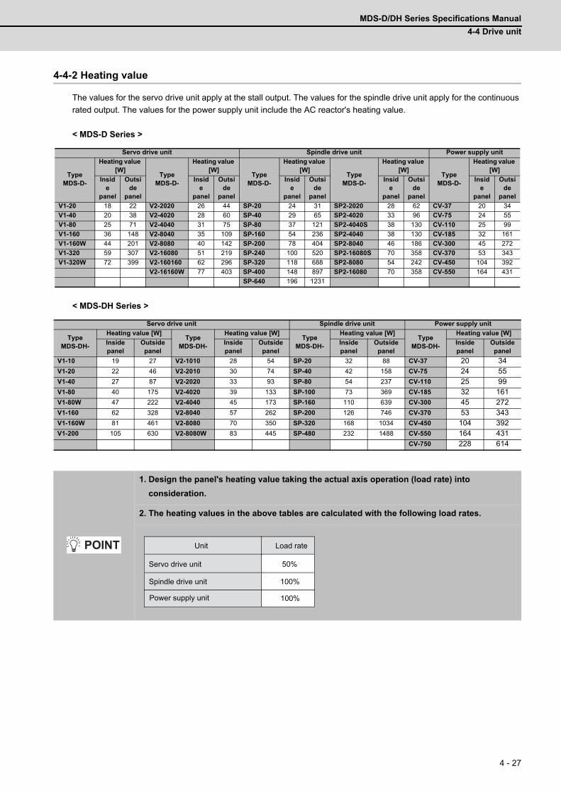
MDS-D/DH Series Specifications Manual
4-4 Drive unit
4 - 27
4-4-2 Heating value
The values for the servo drive unit apply at the stall output. The values for the spindle drive unit apply for the continuous
rated output. The values for the power supply unit include the AC reactor's heating value.
< MDS-D Series >
< MDS-DH Series >
Servo drive unit Spindle drive unit Power supply unit
TypeMDS-D-
Heating value [W]
TypeMDS-D-
Heating value [W]
TypeMDS-D-
Heating value [W]
TypeMDS-D-
Heating value [W]
TypeMDS-D-
Heating value [W]
Inside
panel
Outside
panel
Inside
panel
Outside
panel
Inside
panel
Outside
panel
Inside
panel
Outside
panel
Inside
panel
Outside
panel
V1-20 18 22 V2-2020 26 44 SP-20 24 31 SP2-2020 28 62 CV-37 20 34
V1-40 20 38 V2-4020 28 60 SP-40 29 65 SP2-4020 33 96 CV-75 24 55
V1-80 25 71 V2-4040 31 75 SP-80 37 121 SP2-4040S 38 130 CV-110 25 99
V1-160 36 148 V2-8040 35 109 SP-160 54 236 SP2-4040 38 130 CV-185 32 161
V1-160W 44 201 V2-8080 40 142 SP-200 78 404 SP2-8040 46 186 CV-300 45 272
V1-320 59 307 V2-16080 51 219 SP-240 100 520 SP2-16080S 70 358 CV-370 53 343
V1-320W 72 399 V2-160160 62 296 SP-320 118 688 SP2-8080 54 242 CV-450 104 392
V2-16160W 77 403 SP-400 148 897 SP2-16080 70 358 CV-550 164 431
SP-640 196 1231
Servo drive unit Spindle drive unit Power supply unit
TypeMDS-DH-
Heating value [W]Type
MDS-DH-
Heating value [W]Type
MDS-DH-
Heating value [W]Type
MDS-DH-
Heating value [W]
Inside panel
Outside panel
Inside panel
Outside panel
Inside panel
Outside panel
Inside panel
Outside panel
V1-10 19 27 V2-1010 28 54 SP-20 32 88 CV-37 20 34V1-20 22 46 V2-2010 30 74 SP-40 42 158 CV-75 24 55V1-40 27 87 V2-2020 33 93 SP-80 54 237 CV-110 25 99V1-80 40 175 V2-4020 39 133 SP-100 73 369 CV-185 32 161V1-80W 47 222 V2-4040 45 173 SP-160 110 639 CV-300 45 272V1-160 62 328 V2-8040 57 262 SP-200 126 746 CV-370 53 343V1-160W 81 461 V2-8080 70 350 SP-320 168 1034 CV-450 104 392V1-200 105 630 V2-8080W 83 445 SP-480 232 1488 CV-550 164 431
CV-750 228 614
1. Design the panel's heating value taking the actual axis operation (load rate) into
consideration.
2. The heating values in the above tables are calculated with the following load rates.
POINT
50%
100%
100%
Unit Load rate
Servo drive unit
Spindle drive unit
Power supply unit

4 Characteristics
MITSUBISHI CNC
4 - 28
4-4-3 Drive unit arrangement
Arrange the drive units in the following procedure.
(1) Install a power supply unit.
(2) Arrange drive units in order of the nominal current from largest from the right.
(3) In the arrangement, the clearance between the units is 1 mm.
(4) Arrange the drive units with the DC connection length from the power supply unit being 800mm or less.
For the arrangement of 800mm or more, multiple power supply units are required.
(5) Arrange large capacity drive units at the left of the power supply unit with the clearance between the drive units
being 1mm.
1. Arrange large capacity drive units at the left of the power supply unit with the clearance
between the drive units being 1mm.
2. Power supply units equivalent to the number of large capacity drive units are required.
3. When arranging the drive unit at the right of the large capacity power supply unit, remove
the side protection cover of the power supply unit.
4. MDS-D-SP-400/640, MDS-DH-SP-200/320/480 and MDS-DH-V1-200 are the large capacity
drive units.
Large Small
Arrange drive units in order of nominal current from largest.
Use the dedicated connection bar.
800mm or less
1mm1mm1mm1mm
POINT

MDS-D/DH Series Specifications Manual
4-4 Drive unit
4 - 29
<For separated arrangement of drive units >
Arranging drive units in the horizontal as much as possible is recommended. Thus, if the drive units must be
arranged in the vertical, or if the drive units must be separated by more than 30mm, arrange them with the DC
connection length of 500mm or less.
1. D: For MDS-D-V1-320W, MDS-D-SP-240 to 640, the separated wiring is not available.
DH: For MDS-DH-V1-160W to 200, MDS-DH-SP-160 to 480, the separated wiring is not
available.
2. If the drive units are separated by more than 30mm, twist the wires used for the DC
connection or bundle them with a fixing band in order to prevent two wires from being
separated.
3. Failure to observe the above arrangement could damage the units.
Fixing bandTwist
1mm
1mm
500mm or less
CAUTION

4 Characteristics
MITSUBISHI CNC
4 - 30

5 - 1
5
Dedicated Options
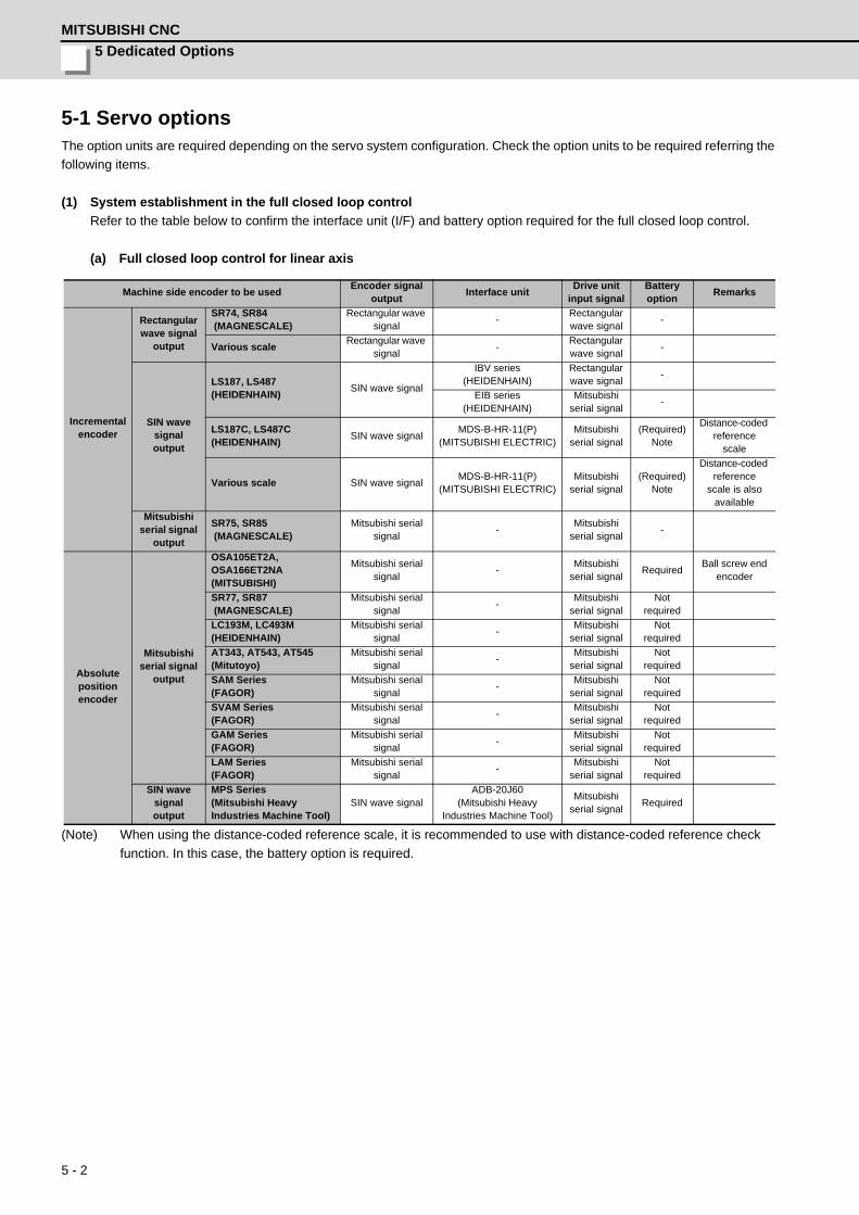
5 Dedicated Options
MITSUBISHI CNC
5 - 2
5-1 Servo optionsThe option units are required depending on the servo system configuration. Check the option units to be required referring the
following items.
(1) System establishment in the full closed loop control
Refer to the table below to confirm the interface unit (I/F) and battery option required for the full closed loop control.
(a) Full closed loop control for linear axis
(Note) When using the distance-coded reference scale, it is recommended to use with distance-coded reference check
function. In this case, the battery option is required.
Machine side encoder to be usedEncoder signal
outputInterface unit
Drive unit input signal
Battery option
Remarks
Incrementalencoder
Rectangular wave signal
output
SR74, SR84 (MAGNESCALE)
Rectangular wave signal
-Rectangular wave signal
-
Various scaleRectangular wave
signal-
Rectangular wave signal
-
SIN wave signal output
LS187, LS487 (HEIDENHAIN)
SIN wave signal
IBV series (HEIDENHAIN)
Rectangular wave signal
-
EIB series (HEIDENHAIN)
Mitsubishi serial signal
-
LS187C, LS487C (HEIDENHAIN)
SIN wave signalMDS-B-HR-11(P)
(MITSUBISHI ELECTRIC)Mitsubishi
serial signal(Required)
Note
Distance-coded reference
scale
Various scale SIN wave signalMDS-B-HR-11(P)
(MITSUBISHI ELECTRIC)Mitsubishi
serial signal(Required)
Note
Distance-coded reference
scale is also available
Mitsubishi serial signal
output
SR75, SR85 (MAGNESCALE)
Mitsubishi serial signal
-Mitsubishi
serial signal-
Absolutepositionencoder
Mitsubishi serial signal
output
OSA105ET2A,OSA166ET2NA(MITSUBISHI)
Mitsubishi serial signal
-Mitsubishi
serial signalRequired
Ball screw end encoder
SR77, SR87 (MAGNESCALE)
Mitsubishi serial signal
-Mitsubishi
serial signalNot
required
LC193M, LC493M (HEIDENHAIN)
Mitsubishi serial signal
-Mitsubishi
serial signalNot
required
AT343, AT543, AT545 (Mitutoyo)
Mitsubishi serial signal
-Mitsubishi
serial signalNot
required
SAM Series (FAGOR)
Mitsubishi serial signal
-Mitsubishi
serial signalNot
required
SVAM Series (FAGOR)
Mitsubishi serial signal
-Mitsubishi
serial signalNot
required
GAM Series (FAGOR)
Mitsubishi serial signal
-Mitsubishi
serial signalNot
required
LAM Series (FAGOR)
Mitsubishi serial signal
-Mitsubishi
serial signalNot
required
SIN wave signal output
MPS Series(Mitsubishi HeavyIndustries Machine Tool)
SIN wave signalADB-20J60
(Mitsubishi Heavy Industries Machine Tool)
Mitsubishi serial signal
Required
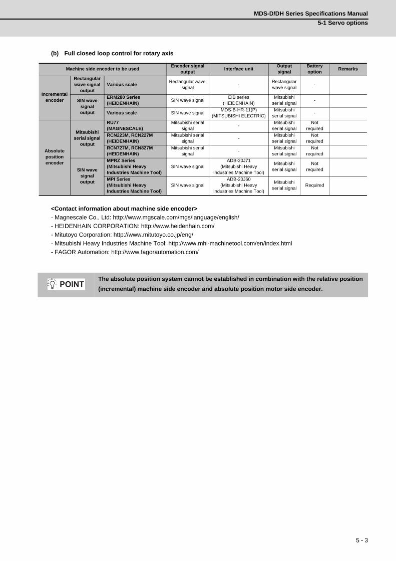
MDS-D/DH Series Specifications Manual
5-1 Servo options
5 - 3
(b) Full closed loop control for rotary axis
<Contact information about machine side encoder>
- Magnescale Co., Ltd: http://www.mgscale.com/mgs/language/english/
- HEIDENHAIN CORPORATION: http://www.heidenhain.com/
- Mitutoyo Corporation: http://www.mitutoyo.co.jp/eng/
- Mitsubishi Heavy Industries Machine Tool: http://www.mhi-machinetool.com/en/index.html
- FAGOR Automation: http://www.fagorautomation.com/
Machine side encoder to be usedEncoder signal
outputInterface unit
Output signal
Battery option
Remarks
Incrementalencoder
Rectangular wave signal
outputVarious scale
Rectangular wave signal
-Rectangular wave signal
-
SIN wave signal output
ERM280 Series (HEIDENHAIN)
SIN wave signalEIB series
(HEIDENHAIN)Mitsubishi
serial signal-
Various scale SIN wave signalMDS-B-HR-11(P)
(MITSUBISHI ELECTRIC)Mitsubishi
serial signal-
Absolutepositionencoder
Mitsubishi serial signal
output
RU77(MAGNESCALE)
Mitsubishi serial signal
-Mitsubishi
serial signalNot
required
RCN223M, RCN227M (HEIDENHAIN)
Mitsubishi serial signal
-Mitsubishi
serial signalNot
required
RCN727M, RCN827M (HEIDENHAIN)
Mitsubishi serial signal
-Mitsubishi
serial signalNot
required
SIN wave signal output
MPRZ Series(Mitsubishi HeavyIndustries Machine Tool)
SIN wave signalADB-20J71
(Mitsubishi Heavy Industries Machine Tool)
Mitsubishi serial signal
Notrequired
MPI Series(Mitsubishi HeavyIndustries Machine Tool)
SIN wave signalADB-20J60
(Mitsubishi Heavy Industries Machine Tool)
Mitsubishi serial signal
Required
The absolute position system cannot be established in combination with the relative position
(incremental) machine side encoder and absolute position motor side encoder. POINT
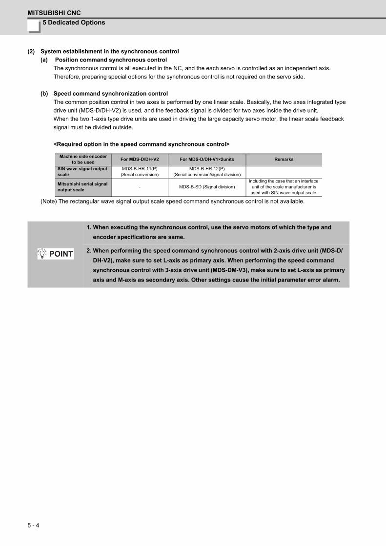
5 Dedicated Options
MITSUBISHI CNC
5 - 4
(2) System establishment in the synchronous control
(a) Position command synchronous control
The synchronous control is all executed in the NC, and the each servo is controlled as an independent axis.
Therefore, preparing special options for the synchronous control is not required on the servo side.
(b) Speed command synchronization control
The common position control in two axes is performed by one linear scale. Basically, the two axes integrated type
drive unit (MDS-D/DH-V2) is used, and the feedback signal is divided for two axes inside the drive unit.
When the two 1-axis type drive units are used in driving the large capacity servo motor, the linear scale feedback
signal must be divided outside.
<Required option in the speed command synchronous control>
(Note) The rectangular wave signal output scale speed command synchronous control is not available.
Machine side encoder to be used
For MDS-D/DH-V2 For MDS-D/DH-V1×2units Remarks
SIN wave signal output scale
MDS-B-HR-11(P)(Serial conversion)
MDS-B-HR-12(P)(Serial conversion/signal division)
Mitsubishi serial signal output scale
- MDS-B-SD (Signal division)Including the case that an interface
unit of the scale manufacturer is used with SIN wave output scale.
1. When executing the synchronous control, use the servo motors of which the type and
encoder specifications are same.
2. When performing the speed command synchronous control with 2-axis drive unit (MDS-D/
DH-V2), make sure to set L-axis as primary axis. When performing the speed command
synchronous control with 3-axis drive unit (MDS-DM-V3), make sure to set L-axis as primary
axis and M-axis as secondary axis. Other settings cause the initial parameter error alarm.
POINT

MDS-D/DH Series Specifications Manual
5-1 Servo options
5 - 5
< Speed command synchronization control system configuration >
1) SIN wave signal output scale
< When using MDS-D/DH-V2 >
For the FB signal of the linear scale, the SIN wave signal is converted to Mitsubishi serial signal with the
encoder conversion unit (MDS-B-HR-11), and that signal is divided to each axis control inside 2-axis drive unit.
<When using two units of MDS-D/DH-V1>
For the FB signal of the linear scale, the SIN wave signal is converted to Mitsubishi serial signal with the
encoder conversion unit (MDS-B-HR-12), and that signal is divided to each drive unit.
CON4
CON3
CON2
CON1
MDS-B-HR-11
MDS-D/DH-V2
Linear scale( SIN wave signal output )
Encoder conversion unitSecondary axis
Primary axis
MDS-B-HR-12
MDS-D/DH-V1 MDS-D/DH-V1
Linear scale( SIN wave signal output )
Encoder conversion unitSecondary axis
Primary axis
(Secondary axis)(Primary axis)
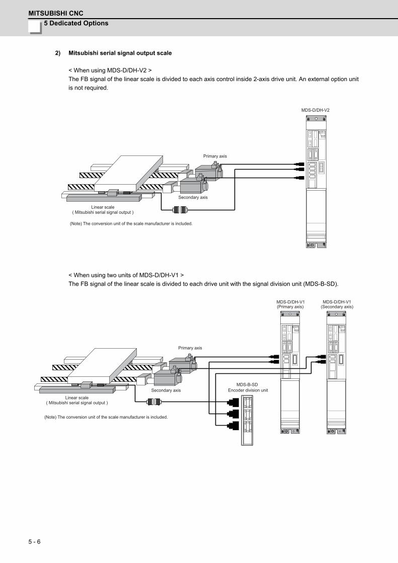
5 Dedicated Options
MITSUBISHI CNC
5 - 6
2) Mitsubishi serial signal output scale
< When using MDS-D/DH-V2 >
The FB signal of the linear scale is divided to each axis control inside 2-axis drive unit. An external option unit
is not required.
< When using two units of MDS-D/DH-V1 >
The FB signal of the linear scale is divided to each drive unit with the signal division unit (MDS-B-SD).
MDS-D/DH-V2
Linear scale( Mitsubishi serial signal output )
Secondary axis
Primary axis
(Note) The conversion unit of the scale manufacturer is included.
MDS-D/DH-V1 MDS-D/DH-V1
MDS-B-SD
(Secondary axis)(Primary axis)
Linear scale( Mitsubishi serial signal output )
(Note) The conversion unit of the scale manufacturer is included.
Encoder division unitSecondary axis
Primary axis
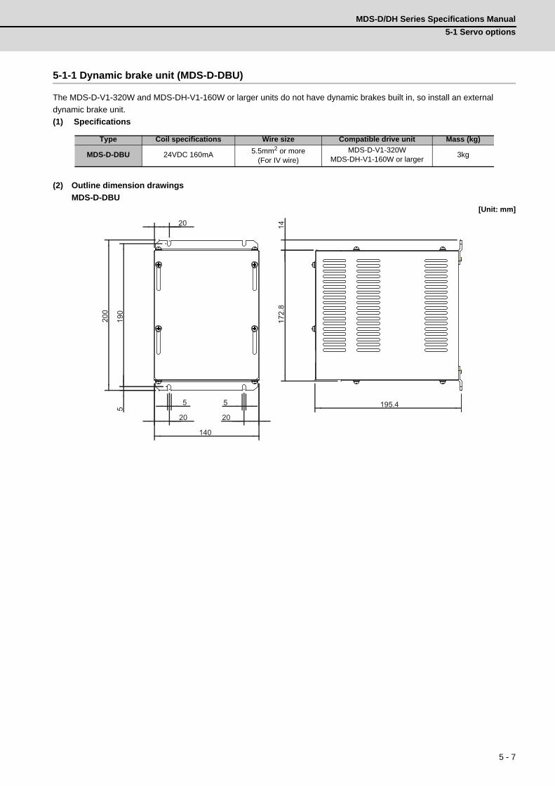
MDS-D/DH Series Specifications Manual
5-1 Servo options
5 - 7
5-1-1 Dynamic brake unit (MDS-D-DBU)
The MDS-D-V1-320W and MDS-DH-V1-160W or larger units do not have dynamic brakes built in, so install an external
dynamic brake unit.
(1) Specifications
(2) Outline dimension drawings
MDS-D-DBU[Unit: mm]
Type Coil specifications Wire size Compatible drive unit Mass (kg)
MDS-D-DBU 24VDC 160mA 5.5mm2 or more(For IV wire)
MDS-D-V1-320WMDS-DH-V1-160W or larger
3kg
5 5
2020
140
5
200
190
20 1417
2.8
195.4
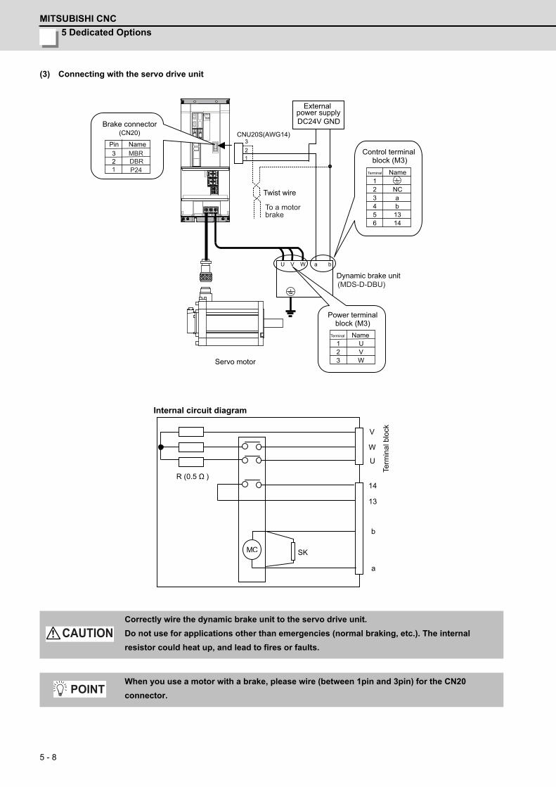
5 Dedicated Options
MITSUBISHI CNC
5 - 8
(3) Connecting with the servo drive unit
Correctly wire the dynamic brake unit to the servo drive unit.
Do not use for applications other than emergencies (normal braking, etc.). The internal
resistor could heat up, and lead to fires or faults.
When you use a motor with a brake, please wire (between 1pin and 3pin) for the CN20
connector.
V
W
U
14
13
b
a
C SK
R (0.5 )
VW
21
3
U
U V W a b
23
NCab1314
56
21
34
DC24V GND
CNU20S(AWG14)(CN20)
23
M
(MDS-D-DBU)
DBRP24
MBR
1
1
Brake connector
Externalpower supply
Twist wire
Control terminal block (M3)
Dynamic brake unit
Power terminalblock (M3)
Internal circuit diagram
Servo motor
Pin Name
Terminal Name
Terminal Name
Term
inal
blo
ck
To a motor brake
CAUTION
POINT
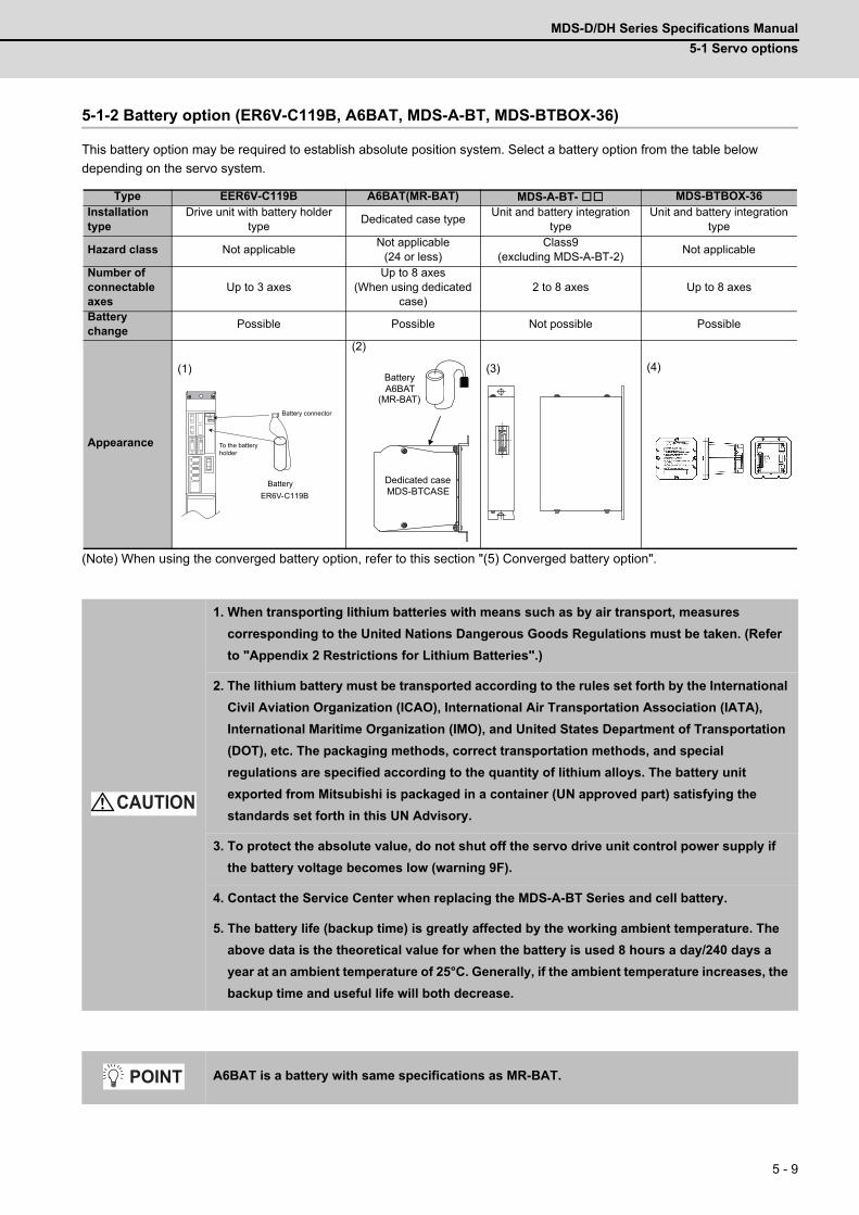
MDS-D/DH Series Specifications Manual
5-1 Servo options
5 - 9
5-1-2 Battery option (ER6V-C119B, A6BAT, MDS-A-BT, MDS-BTBOX-36)
This battery option may be required to establish absolute position system. Select a battery option from the table below
depending on the servo system.
(Note) When using the converged battery option, refer to this section "(5) Converged battery option".
Type EER6V-C119B A6BAT(MR-BAT) MDS-A-BT- MDS-BTBOX-36Installation type
Drive unit with battery holder type
Dedicated case typeUnit and battery integration
typeUnit and battery integration
type
Hazard class Not applicableNot applicable
(24 or less)Class9
(excluding MDS-A-BT-2)Not applicable
Number of connectable axes
Up to 3 axesUp to 8 axes
(When using dedicated case)
2 to 8 axes Up to 8 axes
Battery change
Possible Possible Not possible Possible
Appearance
(1)
(2)
(3) (4)
1. When transporting lithium batteries with means such as by air transport, measures
corresponding to the United Nations Dangerous Goods Regulations must be taken. (Refer
to "Appendix 2 Restrictions for Lithium Batteries".)
2. The lithium battery must be transported according to the rules set forth by the International
Civil Aviation Organization (ICAO), International Air Transportation Association (IATA),
International Maritime Organization (IMO), and United States Department of Transportation
(DOT), etc. The packaging methods, correct transportation methods, and special
regulations are specified according to the quantity of lithium alloys. The battery unit
exported from Mitsubishi is packaged in a container (UN approved part) satisfying the
standards set forth in this UN Advisory.
3. To protect the absolute value, do not shut off the servo drive unit control power supply if
the battery voltage becomes low (warning 9F).
4. Contact the Service Center when replacing the MDS-A-BT Series and cell battery.
5. The battery life (backup time) is greatly affected by the working ambient temperature. The
above data is the theoretical value for when the battery is used 8 hours a day/240 days a
year at an ambient temperature of 25°C. Generally, if the ambient temperature increases, the
backup time and useful life will both decrease.
A6BAT is a battery with same specifications as MR-BAT.
バッテリ
ER6V-C119B
Battery
Battery connector
To the batteryholder
A6BAT
(MR-BAT)
MDS-BTCASE
Battery
Dedicated case
CAUTION
POINT

5 Dedicated Options
MITSUBISHI CNC
5 - 10
(1) Cell battery ( ER6V-C119B )
(a) Specifications
(Note 1) ER6V-C119B is a battery built in a servo drive unit. Install this battery only in the servo drive unit that
executes absolute position control.
(Note 2) This time is a guideline, so does not guarantee the back up time. Replace the battery with a new battery
as soon as a battery warning occurs.
(Note 3) When using ball screw side encoder, both ball screw side encoder and motor side encoder need to be
backed up by a battery, so the number of load shaft should be two.
(b) Installing the cell battery
Open the upper front cover of the servo drive unit.
Connect the battery connector and then put the battery inside.
(Note) When using a cell battery, do not connect the battery unit, MDS-A-BT and MDS-BTBOX-36.
Battery option typeCell battery
ER6V-C119B (Note 1)
Battery model name ER6V
Nominal voltage 3.6V
Nominal capacity 2000mAh
Battery safety
Hazard class -
Battery shape Single battery
Number of batteries used ER6V x 1
Lithium alloy content 0.7g
Mercury content 1g or less
Number of connectable axes Up to 3 axes (Note 3)
Battery continuous backup timeUp to 2 axes: Approx. 10000 hours
3 axes connected: Approx. 6600 hours
Battery useful life(From date of unit manufacture)
7 years
Data save time in battery replacement Approx. 20 hours at time of delivery, approx. 10 hours after 5 years
Back up time from battery warning to alarm occurrence (Note 2)
Up to 2 axes: Approx. 100 hours3 axes connected: Approx. 60 hours
Mass 20g
When using a cell battery built-in drive unit, the wiring between units is not required. The cell
battery can be changed in each drive unit.
BTA
BTB
1 2
1 2 1 2
BT1
BatteryTo battery holder
Battery connector
Battery connector connection part magnified figure
Connector for connecting cell battery
Connect the cell battery with BT1.
POINT
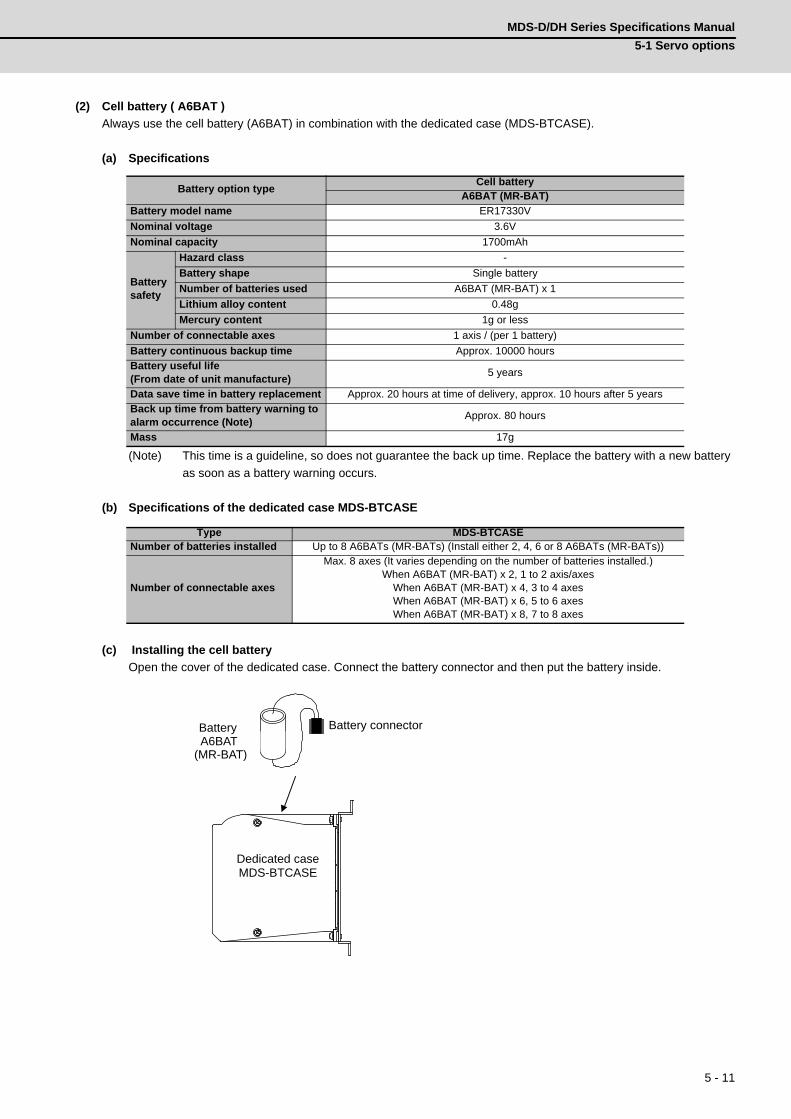
MDS-D/DH Series Specifications Manual
5-1 Servo options
5 - 11
(2) Cell battery ( A6BAT )
Always use the cell battery (A6BAT) in combination with the dedicated case (MDS-BTCASE).
(a) Specifications
(Note) This time is a guideline, so does not guarantee the back up time. Replace the battery with a new battery
as soon as a battery warning occurs.
(b) Specifications of the dedicated case MDS-BTCASE
(c) Installing the cell battery
Open the cover of the dedicated case. Connect the battery connector and then put the battery inside.
Battery option typeCell battery
A6BAT (MR-BAT)
Battery model name ER17330V
Nominal voltage 3.6V
Nominal capacity 1700mAh
Battery safety
Hazard class -
Battery shape Single battery
Number of batteries used A6BAT (MR-BAT) x 1
Lithium alloy content 0.48g
Mercury content 1g or less
Number of connectable axes 1 axis / (per 1 battery)
Battery continuous backup time Approx. 10000 hours
Battery useful life (From date of unit manufacture)
5 years
Data save time in battery replacement Approx. 20 hours at time of delivery, approx. 10 hours after 5 years
Back up time from battery warning to alarm occurrence (Note)
Approx. 80 hours
Mass 17g
Type MDS-BTCASENumber of batteries installed Up to 8 A6BATs (MR-BATs) (Install either 2, 4, 6 or 8 A6BATs (MR-BATs))
Number of connectable axes
Max. 8 axes (It varies depending on the number of batteries installed.)When A6BAT (MR-BAT) x 2, 1 to 2 axis/axes
When A6BAT (MR-BAT) x 4, 3 to 4 axesWhen A6BAT (MR-BAT) x 6, 5 to 6 axesWhen A6BAT (MR-BAT) x 8, 7 to 8 axes
MDS-BTCASE
A6BAT
(MR-BAT)
Battery Battery connector
Dedicated case
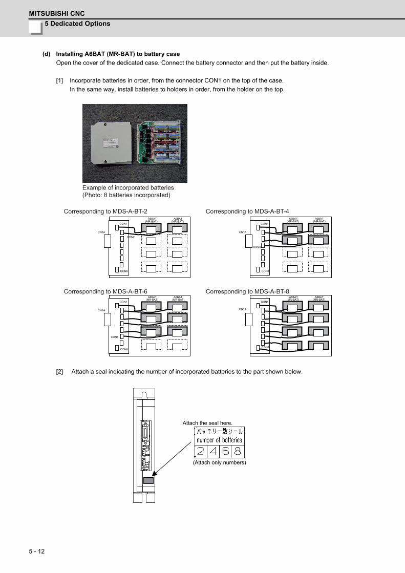
5 Dedicated Options
MITSUBISHI CNC
5 - 12
(d) Installing A6BAT (MR-BAT) to battery case
Open the cover of the dedicated case. Connect the battery connector and then put the battery inside.
[1] Incorporate batteries in order, from the connector CON1 on the top of the case.
In the same way, install batteries to holders in order, from the holder on the top.
[2] Attach a seal indicating the number of incorporated batteries to the part shown below.
CON1
CON8
CON2
A6BAT (MR-BAT)
CN1A
CON1
CON8
CN1A
CON6
CN1A
CON1
CON8
CON1
CON8
CN1A
CON4
A6BAT
A6BAT A6BAT
A6BAT A6BAT A6BAT A6BAT
(MR-BAT)
(MR-BAT) (MR-BAT) (MR-BAT) (MR-BAT)
(MR-BAT) (MR-BAT)
Example of incorporated batteries(Photo: 8 batteries incorporated)
Corresponding to MDS-A-BT-2 Corresponding to MDS-A-BT-4
Corresponding to MDS-A-BT-6 Corresponding to MDS-A-BT-8
(Attach only numbers)
Attach the seal here.
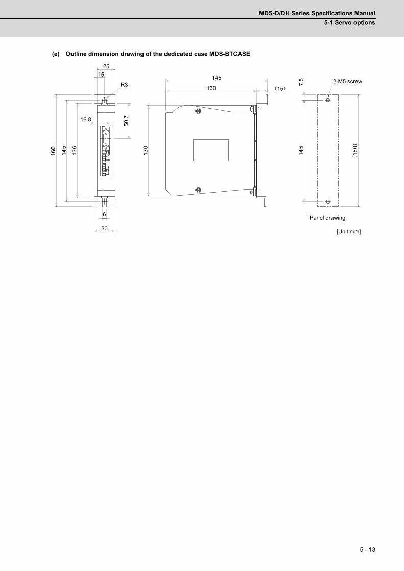
MDS-D/DH Series Specifications Manual
5-1 Servo options
5 - 13
(e) Outline dimension drawing of the dedicated case MDS-BTCASE
130
160
130
30
2513
6
50.7
145
15
15R3
16.8
145
6
145
7.5
160
Panel drawing
[Unit:mm]
2-M5 screw
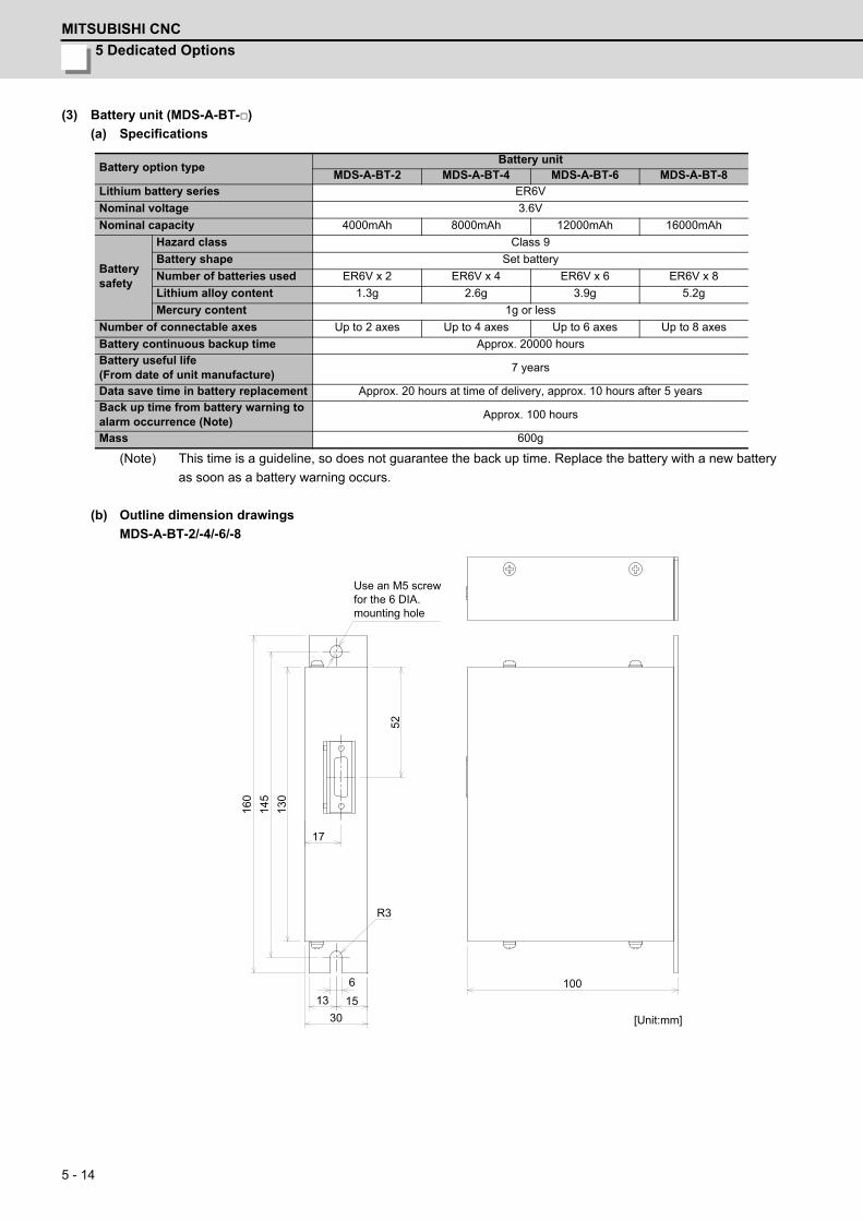
5 Dedicated Options
MITSUBISHI CNC
5 - 14
(3) Battery unit (MDS-A-BT-)
(a) Specifications
(Note) This time is a guideline, so does not guarantee the back up time. Replace the battery with a new battery
as soon as a battery warning occurs.
(b) Outline dimension drawings
MDS-A-BT-2/-4/-6/-8
Battery option typeBattery unit
MDS-A-BT-2 MDS-A-BT-4 MDS-A-BT-6 MDS-A-BT-8
Lithium battery series ER6V
Nominal voltage 3.6V
Nominal capacity 4000mAh 8000mAh 12000mAh 16000mAh
Battery safety
Hazard class Class 9
Battery shape Set battery
Number of batteries used ER6V x 2 ER6V x 4 ER6V x 6 ER6V x 8
Lithium alloy content 1.3g 2.6g 3.9g 5.2g
Mercury content 1g or less
Number of connectable axes Up to 2 axes Up to 4 axes Up to 6 axes Up to 8 axes
Battery continuous backup time Approx. 20000 hours
Battery useful life (From date of unit manufacture)
7 years
Data save time in battery replacement Approx. 20 hours at time of delivery, approx. 10 hours after 5 years
Back up time from battery warning to alarm occurrence (Note)
Approx. 100 hours
Mass 600g
[Unit:mm]
Use an M5 screw for the 6 DIA. mounting hole
100
130
145
15
R3
30
613
17
160
52
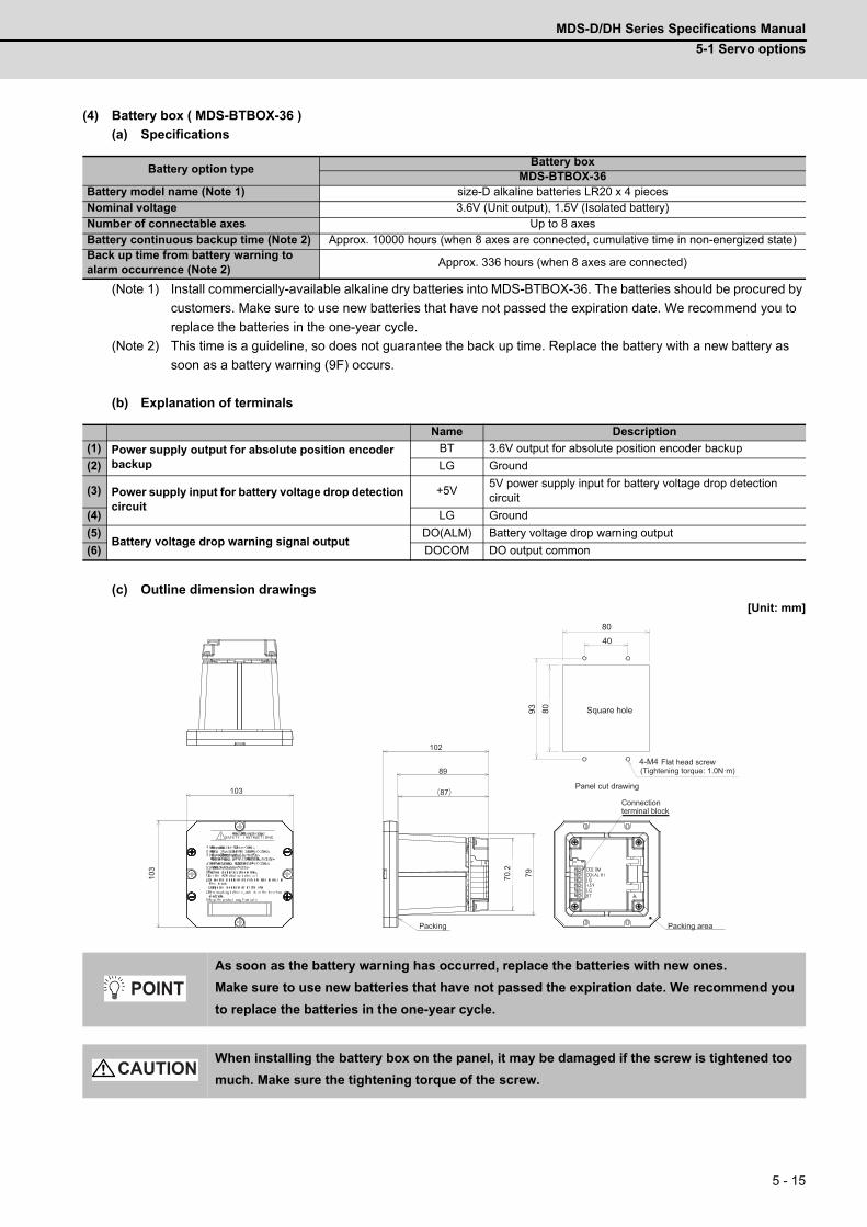
MDS-D/DH Series Specifications Manual
5-1 Servo options
5 - 15
(4) Battery box ( MDS-BTBOX-36 )
(a) Specifications
(Note 1) Install commercially-available alkaline dry batteries into MDS-BTBOX-36. The batteries should be procured by
customers. Make sure to use new batteries that have not passed the expiration date. We recommend you to
replace the batteries in the one-year cycle.
(Note 2) This time is a guideline, so does not guarantee the back up time. Replace the battery with a new battery as
soon as a battery warning (9F) occurs.
(b) Explanation of terminals
(c) Outline dimension drawings[Unit: mm]
Battery option typeBattery box
MDS-BTBOX-36Battery model name (Note 1) size-D alkaline batteries LR20 x 4 piecesNominal voltage 3.6V (Unit output), 1.5V (Isolated battery)Number of connectable axes Up to 8 axesBattery continuous backup time (Note 2) Approx. 10000 hours (when 8 axes are connected, cumulative time in non-energized state)Back up time from battery warning to alarm occurrence (Note 2)
Approx. 336 hours (when 8 axes are connected)
Name Description
(1) Power supply output for absolute position encoder backup
BT 3.6V output for absolute position encoder backup
(2) LG Ground
(3) Power supply input for battery voltage drop detection circuit
+5V5V power supply input for battery voltage drop detection circuit
(4) LG Ground
(5)Battery voltage drop warning signal output
DO(ALM) Battery voltage drop warning output
(6) DOCOM DO output common
As soon as the battery warning has occurred, replace the batteries with new ones.
Make sure to use new batteries that have not passed the expiration date. We recommend you
to replace the batteries in the one-year cycle.
When installing the battery box on the panel, it may be damaged if the screw is tightened too
much. Make sure the tightening torque of the screw.
103
103
102
89
(87)
70.2
7993 80
8040
4-M4
Packing
Connectionterminal block
Packing area
Flat head screw
Panel cut drawing
Square hole
(Tightening torque: 1.0N·m)
POINT
CAUTION
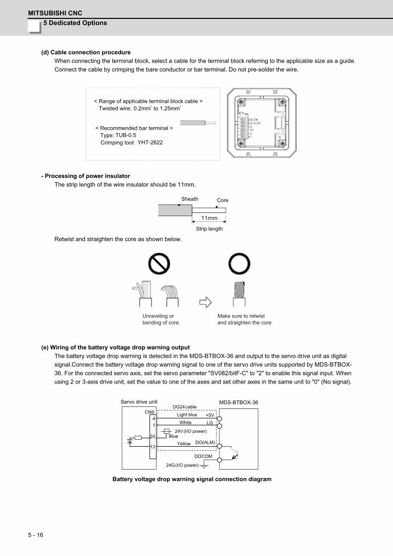
5 Dedicated Options
MITSUBISHI CNC
5 - 16
(d) Cable connection procedure
When connecting the terminal block, select a cable for the terminal block referring to the applicable size as a guide.
Connect the cable by crimping the bare conductor or bar terminal. Do not pre-solder the wire.
- Processing of power insulator
The strip length of the wire insulator should be 11mm.
Retwist and straighten the core as shown below.
(e) Wiring of the battery voltage drop warning output
The battery voltage drop warning is detected in the MDS-BTBOX-36 and output to the servo drive unit as digital
signal.Connect the battery voltage drop warning signal to one of the servo drive units supported by MDS-BTBOX-
36. For the connected servo axis, set the servo parameter "SV082/bitF-C" to "2" to enable this signal input. When
using 2 or 3-axis drive unit, set the value to one of the axes and set other axes in the same unit to "0" (No signal).
Battery voltage drop warning signal connection diagram
2 20.2mm to 1.25mm
TUB-0.5YHT-2622
< Recommended bar terminal >Type: Crimping tool:
Twisted wire: < Range of applicable terminal block cable >
11mm
Strip length
CoreSheath
Make sure to retwistand straighten the core
Unraveling orbending of core
MDS-BTBOX-36
DOCOM
DO(ALM)
24V
+5V LG
CN9 4 1
20
13
DG24
24G
Light blue
White
BlueYellow
cable
(I/O power)
(I/O power)
Servo drive unit
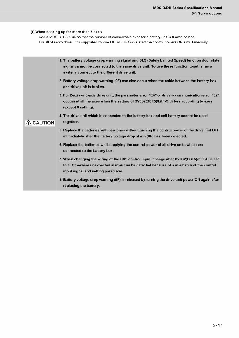
MDS-D/DH Series Specifications Manual
5-1 Servo options
5 - 17
(f) When backing up for more than 8 axes
Add a MDS-BTBOX-36 so that the number of connectable axes for a battery unit is 8 axes or less.
For all of servo drive units supported by one MDS-BTBOX-36, start the control powers ON simultaneously.
1. The battery voltage drop warning signal and SLS (Safely Limited Speed) function door state
signal cannot be connected to the same drive unit. To use these function together as a
system, connect to the different drive unit.
2. Battery voltage drop warning (9F) can also occur when the cable between the battery box
and drive unit is broken.
3. For 2-axis or 3-axis drive unit, the parameter error "E4" or drivers communication error "82"
occurs at all the axes when the setting of SV082(SSF5)/bitF-C differs according to axes
(except 0 setting).
4. The drive unit which is connected to the battery box and cell battery cannot be used
together.
5. Replace the batteries with new ones without turning the control power of the drive unit OFF
immediately after the battery voltage drop alarm (9F) has been detected.
6. Replace the batteries while applying the control power of all drive units which are
connected to the battery box.
7. When changing the wiring of the CN9 control input, change after SV082(SSF5)/bitF-C is set
to 0. Otherwise unexpected alarms can be detected because of a mismatch of the control
input signal and setting parameter.
8. Battery voltage drop warning (9F) is released by turning the drive unit power ON again after
replacing the battery.
CAUTION
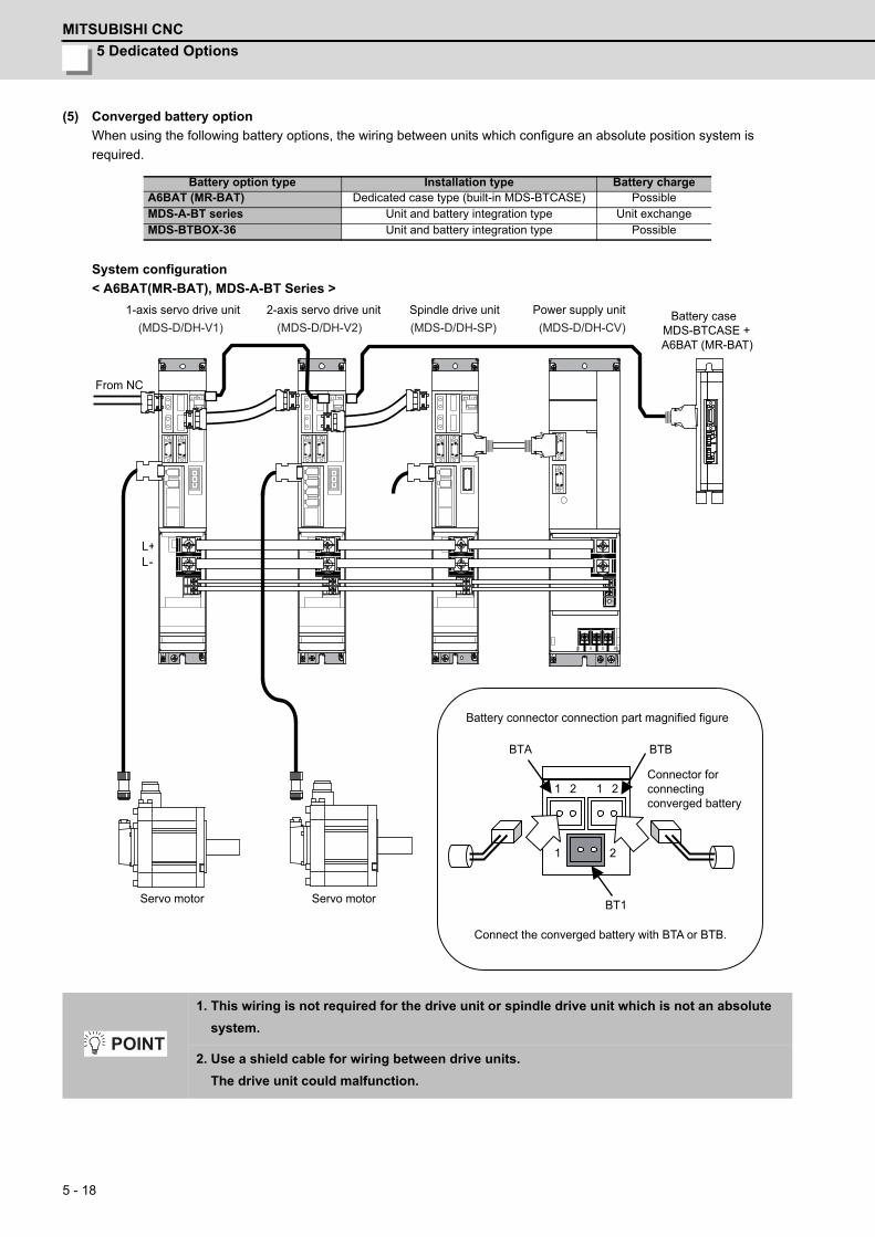
5 Dedicated Options
MITSUBISHI CNC
5 - 18
(5) Converged battery option
When using the following battery options, the wiring between units which configure an absolute position system is
required.
System configuration
< A6BAT(MR-BAT), MDS-A-BT Series >
Battery option type Installation type Battery chargeA6BAT (MR-BAT) Dedicated case type (built-in MDS-BTCASE) PossibleMDS-A-BT series Unit and battery integration type Unit exchangeMDS-BTBOX-36 Unit and battery integration type Possible
1. This wiring is not required for the drive unit or spindle drive unit which is not an absolute
system.
2. Use a shield cable for wiring between drive units.
The drive unit could malfunction.
L+L-
BTA
BT1
1 2
1 2 1 2
BTB
(MDS-D/DH-V1) (MDS-D/DH-V2) (MDS-D/DH-SP) (MDS-D/DH-CV)
1-axis servo drive unit 2-axis servo drive unit Spindle drive unit Power supply unit Battery caseMDS-BTCASE + A6BAT (MR-BAT)
Battery connector connection part magnified figure
Connector forconnecting converged battery
Connect the converged battery with BTA or BTB.
Servo motorServo motor
From NC
POINT
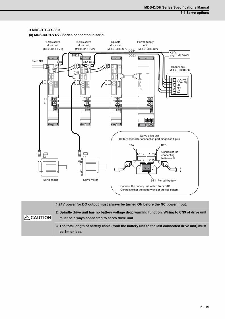
MDS-D/DH Series Specifications Manual
5-1 Servo options
5 - 19
< MDS-BTBOX-36 >
(a) MDS-D/DH-V1/V2 Series connected in serial
1.24V power for DO output must always be turned ON before the NC power input.
2. Spindle drive unit has no battery voltage drop warning function. Wiring to CN9 of drive unit
must be always connected to servo drive unit.
3. The total length of battery cable (from the battery unit to the last connected drive unit) must
be 3m or less.
L+ L-
BTA BTB
1 2
1 2 1 2
CN9
BTB BTB BTA
DG23 DG22
DG24 +24V RG
DOCOM DO(ALM) LG +5V LG BT
MDS-BTBOX-36
(MDS-D/DH-V1) (MDS-D/DH-V2) (MDS-D/DH-SP) (MDS-D/DH-CV)
1-axis servodrive unit
Spindledrive unit
Power supplyunit
BT1 For cell battery
Connect the battery unit with BTA or BTB. Connect either the battery unit or the cell battery.
I/O power
Servo drive unitBattery connector connection part magnified figure
Servo motorServo motor
2-axis servodrive unit
From NC
Battery box
Connector forconnectingbattery unit
CAUTION
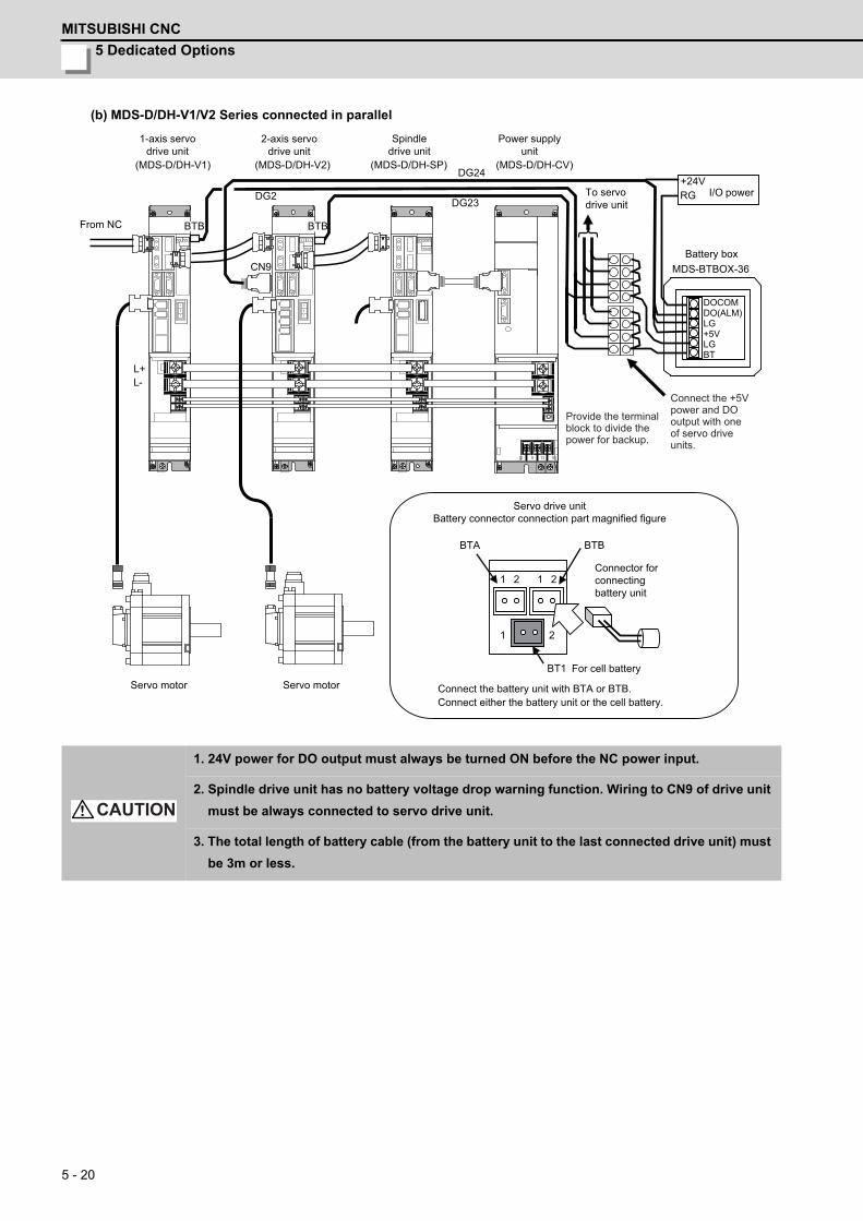
5 Dedicated Options
MITSUBISHI CNC
5 - 20
(b) MDS-D/DH-V1/V2 Series connected in parallel
1. 24V power for DO output must always be turned ON before the NC power input.
2. Spindle drive unit has no battery voltage drop warning function. Wiring to CN9 of drive unit
must be always connected to servo drive unit.
3. The total length of battery cable (from the battery unit to the last connected drive unit) must
be 3m or less.
BTA
BT1
1 2
1 2 1 2
BTB
DOCOM DO(ALM) LG +5V LG BT
MDS-BTBOX-36
DG24
DG23
CN9
BTB BTB
DG2
L+ L-
+24V RG
(MDS-D/DH-V1) (MDS-D/DH-V2) (MDS-D/DH-SP) (MDS-D/DH-CV)
For cell battery
Connect the battery unit with BTA or BTB.Connect either the battery unit or the cell battery.
Servo drive unitBattery connector connection part magnified figure
Connector forconnectingbattery unit
I/O power
Battery box
1-axis servodrive unit
Spindledrive unit
Power supplyunit
2-axis servodrive unit
Servo motorServo motor
From NC
To servodrive unit
Connect the +5V power and DO output with one of servo drive units.
Provide the terminal block to divide the power for backup.
CAUTION
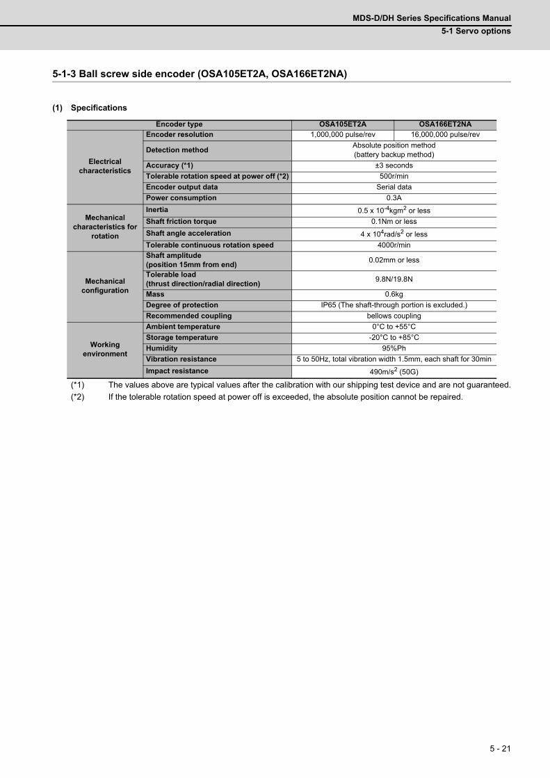
MDS-D/DH Series Specifications Manual
5-1 Servo options
5 - 21
5-1-3 Ball screw side encoder (OSA105ET2A, OSA166ET2NA)
(1) Specifications
(*1) The values above are typical values after the calibration with our shipping test device and are not guaranteed.
(*2) If the tolerable rotation speed at power off is exceeded, the absolute position cannot be repaired.
Encoder type OSA105ET2A OSA166ET2NA
Electrical characteristics
Encoder resolution 1,000,000 pulse/rev 16,000,000 pulse/rev
Detection methodAbsolute position method(battery backup method)
Accuracy (*1) ±3 seconds
Tolerable rotation speed at power off (*2) 500r/min
Encoder output data Serial data
Power consumption 0.3A
Mechanical characteristics for
rotation
Inertia 0.5 x 10⁻⁴kgm2 or less
Shaft friction torque 0.1Nm or less
Shaft angle acceleration 4 x 10⁴rad/s2 or less
Tolerable continuous rotation speed 4000r/min
Mechanical configuration
Shaft amplitude(position 15mm from end)
0.02mm or less
Tolerable load(thrust direction/radial direction)
9.8N/19.8N
Mass 0.6kg
Degree of protection IP65 (The shaft-through portion is excluded.)
Recommended coupling bellows coupling
Working environment
Ambient temperature 0°C to +55°C
Storage temperature -20°C to +85°C
Humidity 95%Ph
Vibration resistance 5 to 50Hz, total vibration width 1.5mm, each shaft for 30min
Impact resistance 490m/s2 (50G)
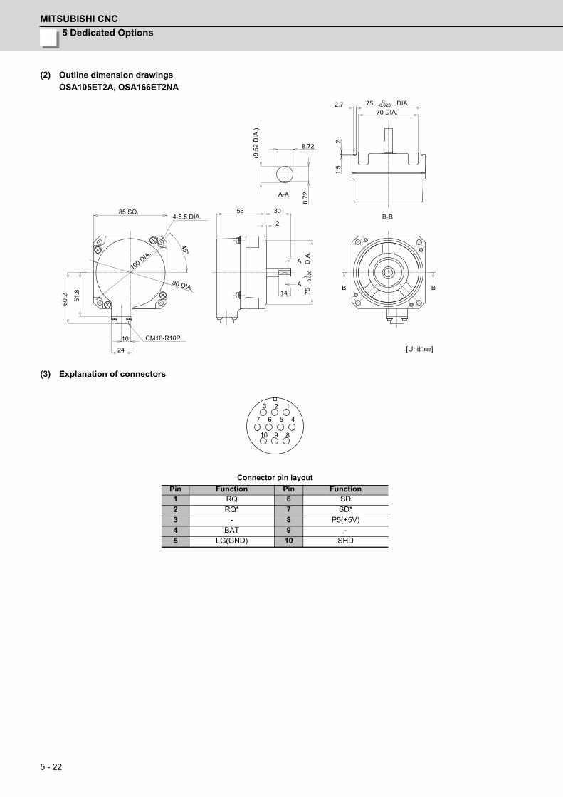
5 Dedicated Options
MITSUBISHI CNC
5 - 22
(2) Outline dimension drawings
OSA105ET2A, OSA166ET2NA
(3) Explanation of connectors
Connector pin layout
Pin Function Pin Function1 RQ 6 SD2 RQ* 7 SD*3 - 8 P5(+5V)4 BAT 9 -5 LG(GND) 10 SHD
70 DIA.75 0
-0.020 DIA.2.7
21.
5
BB
B-B
A
A
30
2
56
14 75
0
-0.0
20 D
IA.
80 DIA.
45°
100 DIA.
85 SQ.
51.8
60.2
8.72
8.72
(9.5
2 D
IA.)
4-5.5 DIA.
10
24
CM10-R10P
A-A
[Unit ]
8
4 5 7 6
9 10
1 2 3

MDS-D/DH Series Specifications Manual
5-1 Servo options
5 - 23
5-1-4 Machine side encoder
The machine side encoders are all other manufacturer's parts, and must be prepared by the user.
(1) Relative position encoder
Depending on the output signal specifications, select a machine side relative position encoder with which the following
(a), (b) or (c) is applied.
(a) Serial signal type (serial conversion unit made by each manufacture)
The following serial conversion unit converts the encoder output signal and transmits the signal to the drive unit in
serial communication.
For details on the specifications of each conversion unit scale and for purchase, contact each corresponding
manufacture directly.
<Contact information about machine side encoder>
- Magnescale Co., Ltd: http://www.mgscale.com/mgs/language/english/
- HEIDENHAIN CORPORATION: http://www.heidenhain.com/
Manufacturer Encoder type Interface unit typeMinimum detection
resolutionTolerable
maximum speed
Magnescale Co., LtdSR75SR85
Not required0.1μm
200m/min0.05μm0.01μm
HEIDENHAIN
LS187, LS187CLS487, LS487C
EIB192M A4 20μm0.0012μm 120m/min
EIB392M A4 20μm
ERM280 1200EIB192M C4 1200 0.0000183°
(19,660,800p/rev)20000r/min
EIB392M C4 1200
ERM280 2048EIB192M C6 2048 0.0000107°
(33,554,432p/rev)11718r/min
EIB392M C6 2048
The above value does not guarantee the accuracy of the system.CAUTION
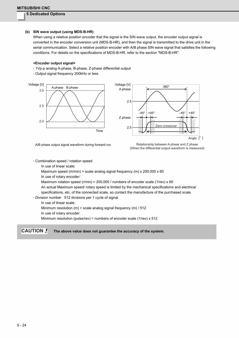
5 Dedicated Options
MITSUBISHI CNC
5 - 24
(b) SIN wave output (using MDS-B-HR)
When using a relative position encoder that the signal is the SIN wave output, the encoder output signal is
converted in the encoder conversion unit (MDS-B-HR), and then the signal is transmitted to the drive unit in the
serial communication. Select a relative position encoder with A/B phase SIN wave signal that satisfies the following
conditions. For details on the specifications of MDS-B-HR, refer to the section "MDS-B-HR".
<Encoder output signal>
- 1Vp-p analog A-phase, B-phase, Z-phase differential output
- Output signal frequency 200kHz or less
- Combination speed / rotation speed
In use of linear scale:
Maximum speed (m/min) = scale analog signal frequency (m) x 200,000 x 60
In use of rotary encoder:
Maximum rotation speed (r/min) = 200,000 / numbers of encoder scale (1/rev) x 60
An actual Maximum speed/ rotary speed is limited by the mechanical specifications and electrical
specifications, etc. of the connected scale, so contact the manufacture of the purchased scale.
- Division number 512 divisions per 1 cycle of signal
In use of linear scale:
Minimum resolution (m) = scale analog signal frequency (m) / 512
In use of rotary encoder:
Minimum resolution (pulse/rev) = numbers of encoder scale (1/rev) x 512
The above value does not guarantee the accuracy of the system.
2.5
360°
-45° +45° -45° +45°
[° ]
3.0
2.5
2.0
2.5
A phase B phaseVoltage [V]
A/B phase output signal waveform during forward run
Time
Voltage [V]A phase
Z phase
Relationship between A phase and Z phase(When the differential output waveform is measured)
Angle
Zero crossover
CAUTION
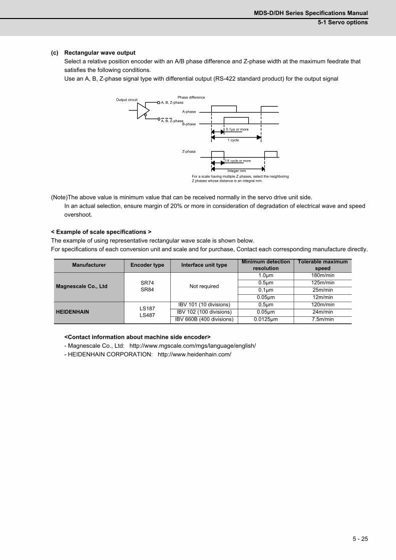
MDS-D/DH Series Specifications Manual
5-1 Servo options
5 - 25
(c) Rectangular wave output
Select a relative position encoder with an A/B phase difference and Z-phase width at the maximum feedrate that
satisfies the following conditions.
Use an A, B, Z-phase signal type with differential output (RS-422 standard product) for the output signal
(Note)The above value is minimum value that can be received normally in the servo drive unit side.
In an actual selection, ensure margin of 20% or more in consideration of degradation of electrical wave and speed
overshoot.
< Example of scale specifications >
The example of using representative rectangular wave scale is shown below.
For specifications of each conversion unit and scale and for purchase, Contact each corresponding manufacture directly.
<Contact information about machine side encoder>
- Magnescale Co., Ltd: http://www.mgscale.com/mgs/language/english/
- HEIDENHAIN CORPORATION: http://www.heidenhain.com/
Manufacturer Encoder type Interface unit typeMinimum detection
resolutionTolerable maximum
speed
Magnescale Co., LtdSR74SR84
Not required
1.0μm 180m/min0.5μm 125m/min0.1μm 25m/min0.05μm 12m/min
HEIDENHAINLS187LS487
IBV 101 (10 divisions) 0.5μm 120m/minIBV 102 (100 divisions) 0.05μm 24m/min
IBV 660B (400 divisions) 0.0125μm 7.5m/min
1/4
Output circuit
A-phase
B-phaseA, B, Z-phase
Z-phase
A, B, Z-phasePhase difference
Integer mmFor a scale having multiple Z phases, select the neighboring Z phases whose distance is an integral mm.
1 cycle
cycle or more
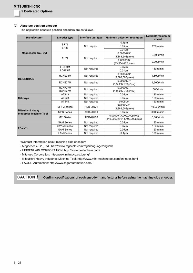
5 Dedicated Options
MITSUBISHI CNC
5 - 26
(2) Absolute position encoder
The applicable absolute position encoders are as follows.
<Contact information about machine side encoder>
- Magnescale Co., Ltd.: http://www.mgscale.com/mgs/language/english/
- HEIDENHAIN CORPORATION: http://www.heidenhain.com/
- Mitutoyo Corporation: http://www.mitutoyo.co.jp/eng/
- Mitsubishi Heavy Industries Machine Tool: http://www.mhi-machinetool.com/en/index.html
- FAGOR Automation: http://www.fagorautomation.com/
Manufacturer Encoder type Interface unit type Minimum detection resolutionTolerable maximum
speed
Magnescale Co., Ltd
SR77SR87
Not required0.1μm
200m/min0.05μm0.01μm
RU77 Not required
0.0000429°(8,388,608p/rev)
2,000r/min
0.0000107(33,554,432p/rev)
2,000r/min
HEIDENHAIN
LC193MLC493M
Not required0.05μm
180m/min0.01μm
RCN223M Not required0.0000429°
(8,388,608p/rev)1,500r/min
RCN227M Not required0.0000027°
(134,217,728p/rev)1,500r/min
RCN727MRCN827M
Not required0.0000027°
(134,217,728p/rev)300r/min
MitutoyoAT343 Not required 0.05μm 120m/minAT543 Not required 0.05μm 150m/minAT545 Not required 0.005μm 150m/min
Mitsubishi HeavyIndustries Machine Tool
MPRZ series ADB-20J710.000043°
(8,388,608p/rev)10,000r/min
MPS Series ADB-20J60 0.05μm 3600m/min
MPI Series ADB-20J600.00005°(7,200,000p/rev)
or 0.000025°(14,400,000p/rev)5,000r/min
FAGOR
SAM Series Not required 0.05μm 120m/minSVAM Series Not required 0.05μm 120m/minGAM Series Not required 0.05μm 120m/minLAM Series Not required 0.1μm 120m/min
Confirm specifications of each encoder manufacturer before using the machine side encoder.CAUTION
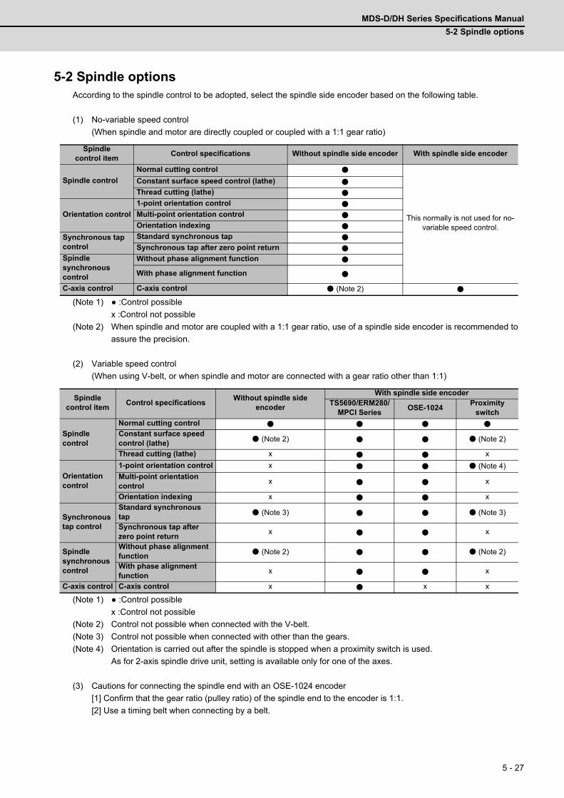
MDS-D/DH Series Specifications Manual
5-2 Spindle options
5 - 27
5-2 Spindle optionsAccording to the spindle control to be adopted, select the spindle side encoder based on the following table.
(1) No-variable speed control
(When spindle and motor are directly coupled or coupled with a 1:1 gear ratio)
(Note 1) :Control possible
x :Control not possible
(Note 2) When spindle and motor are coupled with a 1:1 gear ratio, use of a spindle side encoder is recommended to
assure the precision.
(2) Variable speed control
(When using V-belt, or when spindle and motor are connected with a gear ratio other than 1:1)
(Note 1) :Control possible
x :Control not possible
(Note 2) Control not possible when connected with the V-belt.
(Note 3) Control not possible when connected with other than the gears.
(Note 4) Orientation is carried out after the spindle is stopped when a proximity switch is used.
As for 2-axis spindle drive unit, setting is available only for one of the axes.
(3) Cautions for connecting the spindle end with an OSE-1024 encoder
[1] Confirm that the gear ratio (pulley ratio) of the spindle end to the encoder is 1:1.
[2] Use a timing belt when connecting by a belt.
Spindle control item
Control specifications Without spindle side encoder With spindle side encoder
Spindle control
Normal cutting control
This normally is not used for no-variable speed control.
Constant surface speed control (lathe)
Thread cutting (lathe)
Orientation control
1-point orientation control
Multi-point orientation control
Orientation indexing
Synchronous tap control
Standard synchronous tap
Synchronous tap after zero point return
Spindle synchronous control
Without phase alignment function
With phase alignment function
C-axis control C-axis control (Note 2)
Spindle control item
Control specificationsWithout spindle side
encoder
With spindle side encoderTS5690/ERM280/
MPCI SeriesOSE-1024
Proximity switch
Spindle control
Normal cutting control
Constant surface speed control (lathe) (Note 2) (Note 2)
Thread cutting (lathe) x x
Orientation control
1-point orientation control x (Note 4)
Multi-point orientation control
x x
Orientation indexing x x
Synchronous tap control
Standard synchronous tap
(Note 3) (Note 3)
Synchronous tap after zero point return
x x
Spindle synchronous control
Without phase alignment function
(Note 2) (Note 2)
With phase alignment function
x x
C-axis control C-axis control x x x
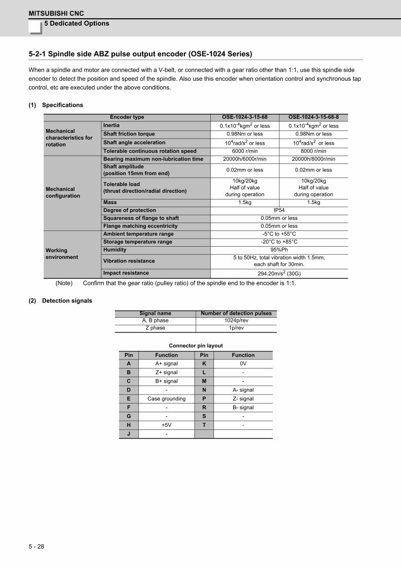
5 Dedicated Options
MITSUBISHI CNC
5 - 28
5-2-1 Spindle side ABZ pulse output encoder (OSE-1024 Series)
When a spindle and motor are connected with a V-belt, or connected with a gear ratio other than 1:1, use this spindle side
encoder to detect the position and speed of the spindle. Also use this encoder when orientation control and synchronous tap
control, etc are executed under the above conditions.
(1) Specifications
(Note) Confirm that the gear ratio (pulley ratio) of the spindle end to the encoder is 1:1.
(2) Detection signals
Connector pin layout
Encoder type OSE-1024-3-15-68 OSE-1024-3-15-68-8
Mechanical characteristics for rotation
Inertia 0.1x10⁻⁴kgm2 or less 0.1x10⁻⁴kgm2 or less
Shaft friction torque 0.98Nm or less 0.98Nm or less
Shaft angle acceleration 104rad/s2 or less 104rad/s2 or less
Tolerable continuous rotation speed 6000 r/min 8000 r/min
Mechanical configuration
Bearing maximum non-lubrication time 20000h/6000r/min 20000h/8000r/min
Shaft amplitude(position 15mm from end)
0.02mm or less 0.02mm or less
Tolerable load(thrust direction/radial direction)
10kg/20kg Half of value
during operation
10kg/20kg Half of value
during operation
Mass 1.5kg 1.5kg
Degree of protection IP54
Squareness of flange to shaft 0.05mm or less
Flange matching eccentricity 0.05mm or less
Working environment
Ambient temperature range -5°C to +55°C
Storage temperature range -20°C to +85°C
Humidity 95%Ph
Vibration resistance5 to 50Hz, total vibration width 1.5mm,
each shaft for 30min.
Impact resistance 294.20m/s2 (30G)
Signal name Number of detection pulsesA, B phase 1024p/rev
Z phase 1p/rev
Pin Function Pin Function
A A+ signal K 0V
B Z+ signal L -
C B+ signal M -
D - N A- signal
E Case grounding P Z- signal
F - R B- signal
G - S -
H +5V T -
J -
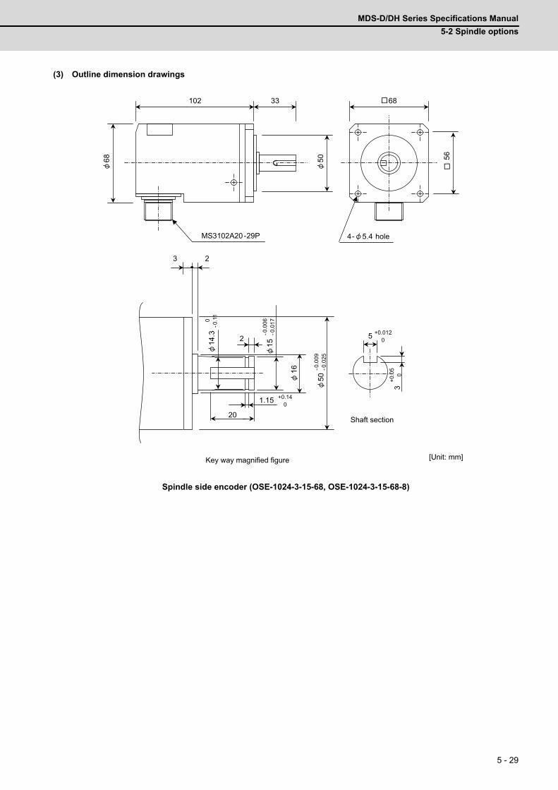
MDS-D/DH Series Specifications Manual
5-2 Spindle options
5 - 29
(3) Outline dimension drawings
Spindle side encoder (OSE-1024-3-15-68, OSE-1024-3-15-68-8)
3 2
14.3
2
1.15 +0.14 0
15 -0
.006
-0
.017
16
50 -0
.009
-0
.025
0 -0
.11
20
5 +0.012 0
3 +0
.05
0
68
MS3102A20-29P
68
102 33
50
56
4- 5.4 hole
Shaft section
Key way magnified figure [Unit: mm]
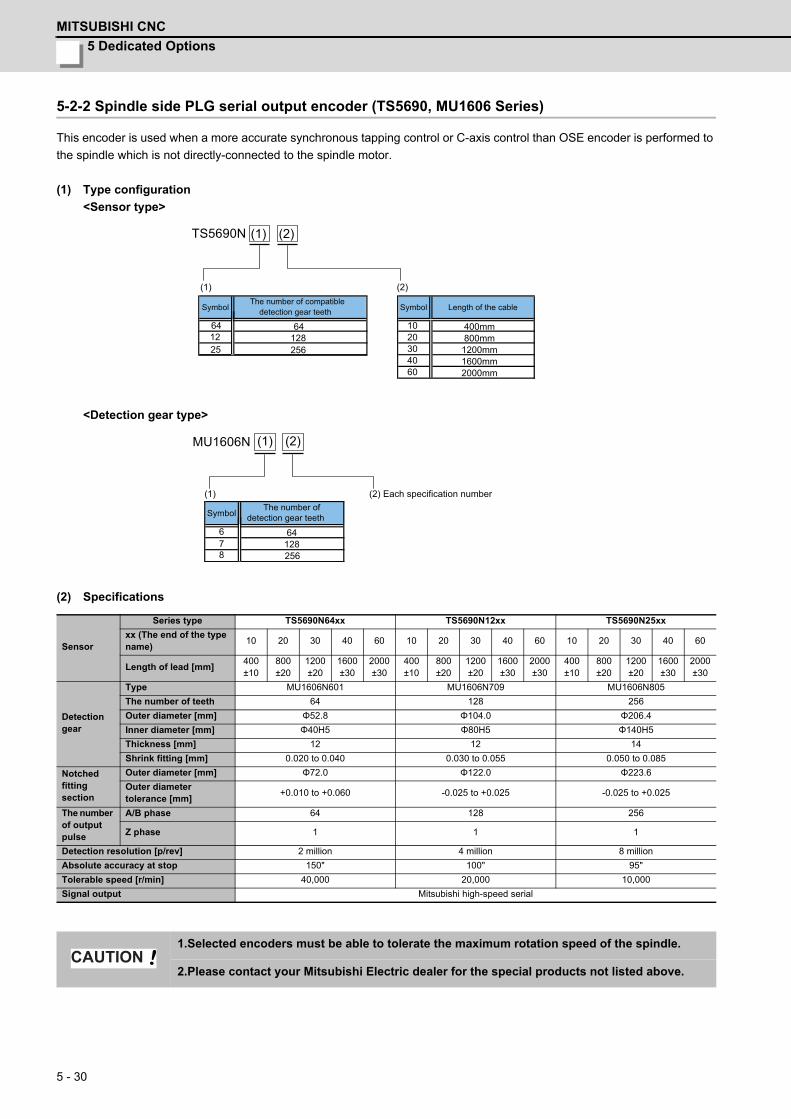
5 Dedicated Options
MITSUBISHI CNC
5 - 30
5-2-2 Spindle side PLG serial output encoder (TS5690, MU1606 Series)
This encoder is used when a more accurate synchronous tapping control or C-axis control than OSE encoder is performed to
the spindle which is not directly-connected to the spindle motor.
(1) Type configuration
<Sensor type>
<Detection gear type>
(2) Specifications
Sensor
Series type TS5690N64xx TS5690N12xx TS5690N25xx
xx (The end of the type name)
10 20 30 40 60 10 20 30 40 60 10 20 30 40 60
Length of lead [mm]400±10
800±20
1200±20
1600±30
2000±30
400±10
800±20
1200±20
1600±30
2000±30
400±10
800±20
1200±20
1600±30
2000±30
Detection gear
Type MU1606N601 MU1606N709 MU1606N805
The number of teeth 64 128 256
Outer diameter [mm] Φ52.8 Φ104.0 Φ206.4
Inner diameter [mm] Φ40H5 Φ80H5 Φ140H5
Thickness [mm] 12 12 14
Shrink fitting [mm] 0.020 to 0.040 0.030 to 0.055 0.050 to 0.085
Notched fitting section
Outer diameter [mm] Φ72.0 Φ122.0 Φ223.6
Outer diameter tolerance [mm]
+0.010 to +0.060 -0.025 to +0.025 -0.025 to +0.025
The number of output pulse
A/B phase 64 128 256
Z phase 1 1 1
Detection resolution [p/rev] 2 million 4 million 8 million
Absolute accuracy at stop 150" 100" 95"
Tolerable speed [r/min] 40,000 20,000 10,000
Signal output Mitsubishi high-speed serial
1.Selected encoders must be able to tolerate the maximum rotation speed of the spindle.
2.Please contact your Mitsubishi Electric dealer for the special products not listed above.
64 64 10 400mm20 800mm12 12830 1200mm40 1600mm
25 256
60 2000mm
TS5690N
(1) (2)
(1) (2)
SymbolThe number of compatible
detection gear teeth Symbol Length of the cable
6 647 1288 256
MU1606N
(2) Each specification number
SymbolThe number of
detection gear teeth
(1)
(1) (2)
CAUTION

MDS-D/DH Series Specifications Manual
5-2 Spindle options
5 - 31
(3) Outline dimension drawings
<TS5690N64xx + MU1606N601>[Unit: mm]
Always apply the notched fitting section machining with the specified dimensions to the
sensor installation surface.CAUTION
RQ MT1
9 8 7456
3 2 1MT2
RQ*SDSD*
+5V5GFG
72 +0
.060
+0.0
10
16
2214
3
51.4
R1
18.7 31
.1
40H
5 +0
.011
0
C0.5
5.5
7
C0.5
29
A
100±10
5
16.5
3.3
10.3
A
MU1606N6011200±201600±302000±30
TS5690N6420TS5690N6430TS5690N6440TS5690N6460
TS5690N6410800±20400±10
8
0.3
±0.0
514.5
3850
23.7
12
4
2- 5.8
Sensor mounting face
Round crimp contact for thermistor 0.5-4(For M4 screw) Output connector (by Tyco Electronics)
Housing (Cap) #172161-1Contact (Socket) #170365-4Accessories (Note 5)Housing (Plug) #172169-1 Qty : 1Contact (Pin) #170363-4 Qty : 9
Name plateSensor model andSerial No. written
Ground
Gap
C part(Note 2)
D part (Note 3)2 hole for identification
Detection gear
Projection forconnector lock
Seen from Arrow APin layout of output connector
Encoder mounting face of machine side
SensorParts name Lead wire length A [mm]
Detection gearParts name
(Note 1) Handle with care as this is a precision component.Pay special attention not to apply excessive external force on the sensor’s detection face. Applying such force will cause a fault.In installing the sensor, keep the protruding fitting of 72 mmon the machine side, and push the C part of the sensor mounting seatagainst the fitting.
+ 0.060+ 0.010
In installing the detection gear, make sure that the D part side comesthe opposite side of the sensor installation side (sensor’s lead wire side).The diviation of the center of the detection gear is 16.5±0.25mm from the sensor mounting face.A connector of the signal cable side (one plug and nine pins) is attached.
The number of teeth 64 (For A, B phase signals)
One notch (For Z phase signal)
Det
ectio
n ge
ar o
uter
DIA
52
.8
Central line ofdetection gear (Note 4)
Sensor mounting face (Note 4)
(Note 2)
(Note 3)
(Note 4)
(Note 5)
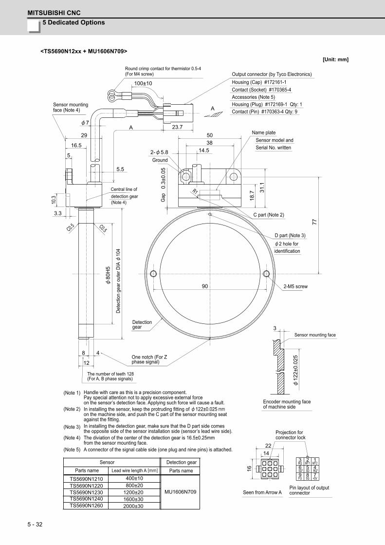
5 Dedicated Options
MITSUBISHI CNC
5 - 32
<TS5690N12xx + MU1606N709>[Unit: mm]
RQ MT1
9 8 7456
3 2 1MT2
RQ*SDSD*
+5V5GFG
122±
0.02
5
16
22
3
48
12
80H
5
90
14
14.5
5.5
77
C0.5 C0.5
7
29A 23.7
100±10
A
5
R1
16.5
18.7 31
.1
3.3
10.3
2- 5.8
3850
0.3±
0.05
MU1606N7091200±201600±302000±30
TS5690N1220TS5690N1230TS5690N1240TS5690N1260
TS5690N1210800±20400±10
Dete
ctio
n ge
ar o
uter
DIA
10
4
Round crimp contact for thermistor 0.5-4(For M4 screw) Output connector (by Tyco Electronics)
Housing (Cap) #172161-1Contact (Socket) #170365-4 Accessories (Note 5)Housing (Plug) #172169-1 Qty: 1Contact (Pin) #170363-4 Qty: 9
Name plateSensor model andSerial No. written
GroundG
ap
C part (Note 2)
D part (Note 3)2 hole for
identification
2-M5 screw
Sensor mounting face
Encoder mounting face of machine side
Projection for connector lock
Seen from Arrow APin layout of output connector
SensorParts name Lead wire length A [mm]
Detection gearParts name
The number of teeth 128 (For A, B phase signals)
One notch (For Zphase signal)
Detectiongear
Central line ofdetection gear(Note 4)
Sensor mountingface (Note 4)
(Note 1) Handle with care as this is a precision component.Pay special attention not to apply excessive external force on the sensor’s detection face. Applying such force will cause a fault.In installing the sensor, keep the protruding fitting of 122±0.025 mmon the machine side, and push the C part of the sensor mounting seatagainst the fitting.In installing the detection gear, make sure that the D part side comesthe opposite side of the sensor installation side (sensor’s lead wire side).The diviation of the center of the detection gear is 16.5±0.25mm from the sensor mounting face.A connector of the signal cable side (one plug and nine pins) is attached.
(Note 2)
(Note 3)
(Note 4)
(Note 5)
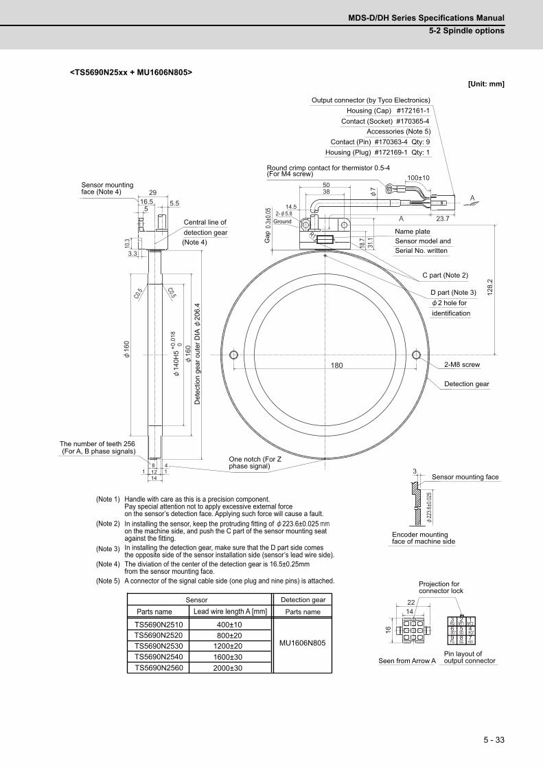
MDS-D/DH Series Specifications Manual
5-2 Spindle options
5 - 33
<TS5690N25xx + MU1606N805>[Unit: mm]
FG 5G +5V
SD* SD RQ*
MT2123
6 5 4789
MT1RQ
5.5
C0.5
C0.5
160
160
140H
5 +0
.018
0
180
10.3
3.3
29
12 1114
8 4
516.5
14.5
7
A
100±10
23.7A
1422
16
3
223.6
±0.02
5
0.3±
0.05
128.
2
R1
18.7
31.1
2- 5.8
3850
MU1606N805TS5690N2520TS5690N2510
1200±201600±302000±30
TS5690N2530TS5690N2540TS5690N2560
800±20400±10
(Note 1) Handle with care as this is a precision component.Pay special attention not to apply excessive external force on the sensor’s detection face. Applying such force will cause a fault.In installing the sensor, keep the protruding fitting of 223.6±0.025 mmon the machine side, and push the C part of the sensor mounting seatagainst the fitting.In installing the detection gear, make sure that the D part side comesthe opposite side of the sensor installation side (sensor’s lead wire side).The diviation of the center of the detection gear is 16.5±0.25mm from the sensor mounting face.A connector of the signal cable side (one plug and nine pins) is attached.
(Note 2)
(Note 3)
(Note 4)
(Note 5)
Housing (Cap) #172161-1Output connector (by Tyco Electronics)
Sensor mountingface (Note 4)
Central line ofdetection gear
Round crimp contact for thermistor 0.5-4(For M4 screw)
Contact (Socket) #170365-4Accessories (Note 5)
Contact (Pin) #170363-4 Qty: 9Housing (Plug) #172169-1 Qty: 1
Name plateSensor model andSerial No. written
C part (Note 2)
D part (Note 3)2 hole for
identification
2-M8 screw
Detection gear
Sensor mounting face
Encoder mounting face of machine side
Projection forconnector lock
Seen from Arrow APin layout ofoutput connector
Sensor
Parts name Lead wire length A [mm]Detection gear
Parts name
The number of teeth 256(For A, B phase signals)
One notch (For Z phase signal)
Det
ectio
n ge
ar o
uter
DIA
20
6.4
Gap
Ground
(Note 4)

5 Dedicated Options
MITSUBISHI CNC
5 - 34
5-2-3 Spindle side accuracy serial output encoder (ERM280, MPCI Series)
C-axis control encoder is used in order to perform an accurate C-axis control.
<Contact information about machine side encoder>
- HEIDENHAIN CORPORATION: http://www.heidenhain.com/
- Mitsubishi Heavy Industries Machine Tool: http://www.mhi-machinetool.com/en/index.html
5-2-4 Machine side encoder
Refer to the section "5-1-4 Machine side encoder".
Manufacturer Encoder type Interface unit typeMinimum detection
resolutionTolerable maximum
speed
HEIDENHAINERM280 1200
EIB192M C4 1200 0.0000183°(19,660,800p/rev)
20000 r/minEIB392M C4 1200
ERM280 2048EIB192M C6 2048 0.0000107°
(33,554,432p/rev)11718 r/min
EIB392M C6 2048Mitsubishi Heavy
Industries Machine ToolMPCI series ADB-20J20
0.00005°(7200000p/rev)
10000 r/min
Confirm specifications of each encoder manufacturer before using the machine side encoder.CAUTION
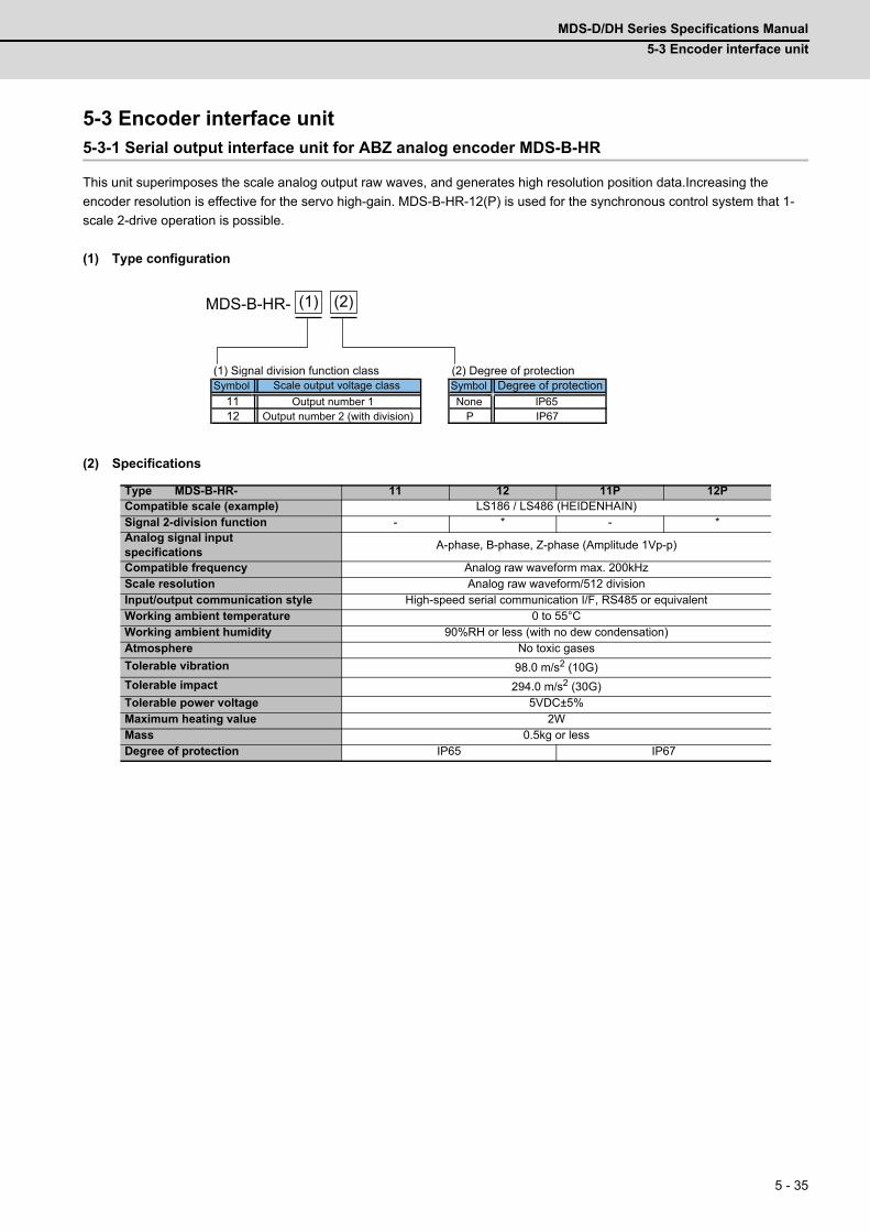
MDS-D/DH Series Specifications Manual
5-3 Encoder interface unit
5 - 35
5-3 Encoder interface unit5-3-1 Serial output interface unit for ABZ analog encoder MDS-B-HR
This unit superimposes the scale analog output raw waves, and generates high resolution position data.Increasing the
encoder resolution is effective for the servo high-gain. MDS-B-HR-12(P) is used for the synchronous control system that 1-
scale 2-drive operation is possible.
(1) Type configuration
(2) Specifications
Type MDS-B-HR- 11 12 11P 12PCompatible scale (example) LS186 / LS486 (HEIDENHAIN)Signal 2-division function - * - *Analog signal input specifications
A-phase, B-phase, Z-phase (Amplitude 1Vp-p)
Compatible frequency Analog raw waveform max. 200kHzScale resolution Analog raw waveform/512 divisionInput/output communication style High-speed serial communication I/F, RS485 or equivalentWorking ambient temperature 0 to 55°CWorking ambient humidity 90%RH or less (with no dew condensation)Atmosphere No toxic gases
Tolerable vibration 98.0 m/s2 (10G)
Tolerable impact 294.0 m/s2 (30G)Tolerable power voltage 5VDC±5%Maximum heating value 2WMass 0.5kg or lessDegree of protection IP65 IP67
11 IP6512 P IP67
MDS-B-HR- (1) (2)
(1) Signal division function class (2) Degree of protectionSymbol Scale output voltage class Symbol Degree of protection
Output number 1 NoneOutput number 2 (with division)
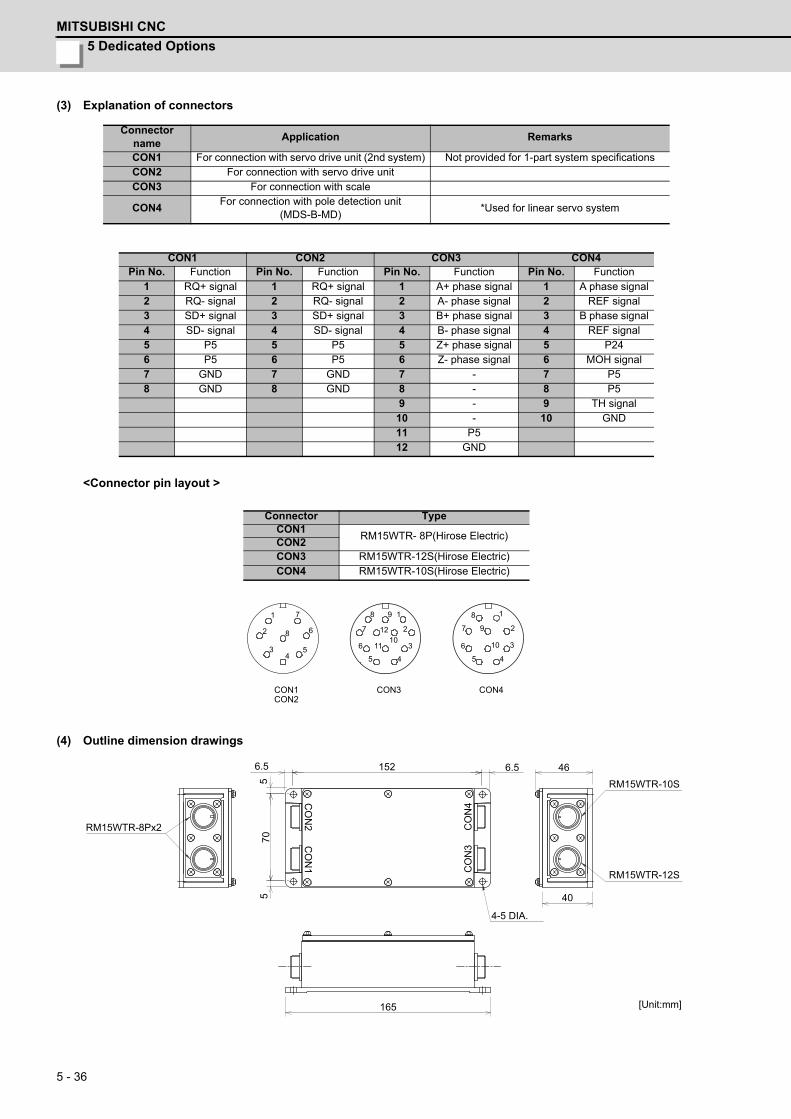
5 Dedicated Options
MITSUBISHI CNC
5 - 36
(3) Explanation of connectors
<Connector pin layout >
(4) Outline dimension drawings
Connector name
Application Remarks
CON1 For connection with servo drive unit (2nd system) Not provided for 1-part system specificationsCON2 For connection with servo drive unitCON3 For connection with scale
CON4For connection with pole detection unit
(MDS-B-MD)*Used for linear servo system
CON1 CON2 CON3 CON4Pin No. Function Pin No. Function Pin No. Function Pin No. Function
1 RQ+ signal 1 RQ+ signal 1 A+ phase signal 1 A phase signal2 RQ- signal 2 RQ- signal 2 A- phase signal 2 REF signal3 SD+ signal 3 SD+ signal 3 B+ phase signal 3 B phase signal4 SD- signal 4 SD- signal 4 B- phase signal 4 REF signal5 P5 5 P5 5 Z+ phase signal 5 P246 P5 6 P5 6 Z- phase signal 6 MOH signal7 GND 7 GND 7 - 7 P58 GND 8 GND 8 - 8 P5
9 - 9 TH signal10 - 10 GND11 P512 GND
Connector TypeCON1
RM15WTR- 8P(Hirose Electric)CON2CON3 RM15WTR-12S(Hirose Electric)CON4 RM15WTR-10S(Hirose Electric)
2
1
3 4
5
6
7
8
8
7
6
5 4
3
2
1 9
12
11 10
CON1 CON2
CON3 CON4
1
2
3
4 5
6
7
8
9
10
[Unit:mm]
RM15WTR-10S
RM15WTR-12S
55
70
6.51526.5
165
46
RM15WTR-8Px2
40
4-5 DIA.
CO
N1
CO
N2 C
ON
4C
ON
3
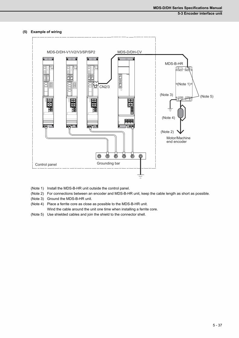
MDS-D/DH Series Specifications Manual
5-3 Encoder interface unit
5 - 37
(5) Example of wiring
(Note 1) Install the MDS-B-HR unit outside the control panel.
(Note 2) For connections between an encoder and MDS-B-HR unit, keep the cable length as short as possible.
(Note 3) Ground the MDS-B-HR unit.
(Note 4) Place a ferrite core as close as possible to the MDS-B-HR unit.
Wind the cable around the unit one time when installing a ferrite core.
(Note 5) Use shielded cables and join the shield to the connector shell.
MDS-D/DH-V1/V2/V3/SP/SP2
CN2/3
MDS-B-HR
MDS-D/DH-CV
CON3 CON4
CON2CON1
Control panel Grounding bar
Motor/Machine end encoder
(Note 1)
(Note 4)
(Note 2)
(Note 3) (Note 5)
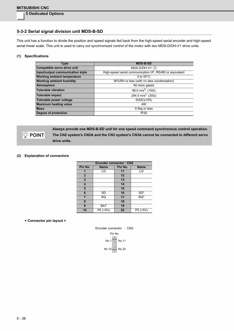
5 Dedicated Options
MITSUBISHI CNC
5 - 38
5-3-2 Serial signal division unit MDS-B-SD
This unit has a function to divide the position and speed signals fed back from the high-speed serial encoder and high-speed
serial linear scale. This unit is used to carry out synchronized control of the motor with two MDS-D/DH-V1 drive units.
(1) Specifications
(2) Explanation of connectors
< Connector pin layout >
Type MDS-B-SDCompatible servo drive unit MDS-D/DH-V1- Input/output communication style High-speed serial communication I/F, RS485 or equivalentWorking ambient temperature 0 to 55°CWorking ambient humidity 90%RH or less (with no dew condensation)Atmosphere No toxic gases
Tolerable vibration 98.0 m/s2 (10G)
Tolerable impact 294.0 m/s2 (30G)Tolerable power voltage 5VDC±10%Maximum heating value 4WMass 0.5kg or lessDegree of protection IP20
Always provide one MDS-B-SD unit for one speed command synchronous control operation.
The CN2 system's CN2A and the CN3 system's CN3A cannot be connected to different servo
drive units.
Encoder connector : CN2Pin No. Name Pin No. Name
1 LG 11 LG2 123 134 145 156 SD 16 SD*7 RQ 17 RQ*8 189 BAT 1910 P5 (+5V) 20 P5 (+5V)
POINT
CN2
Pin No.
Encoder connector
No.11
No.20
No.1
No.10
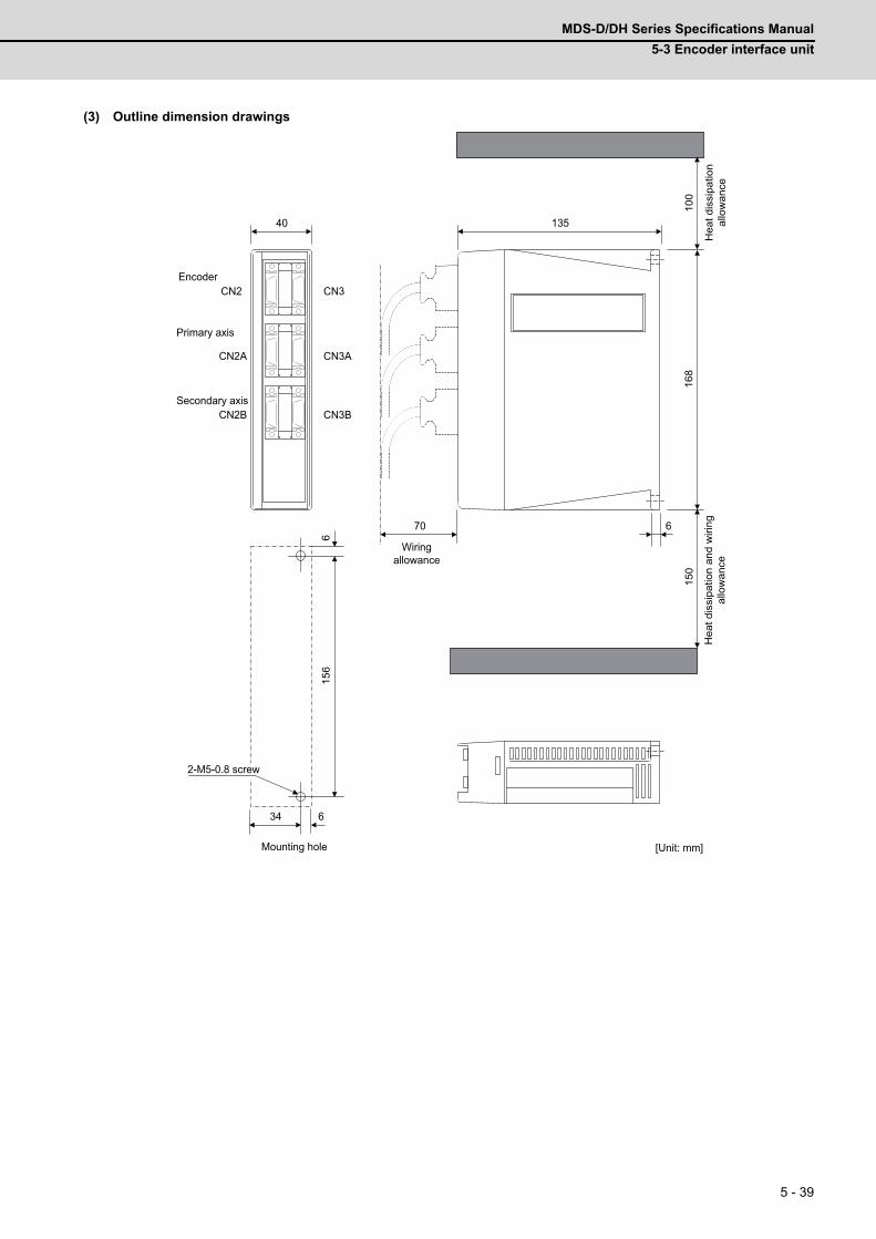
MDS-D/DH Series Specifications Manual
5-3 Encoder interface unit
5 - 39
(3) Outline dimension drawings
40 135
168
CN2
CN2A
CN2B
CN3
CN3A
CN3B
100
150
70 6
34 6
156
6
Hea
t dis
sipa
tion
allo
wan
ce
Encoder
Primary axis
Secondary axis
Wiringallowance
2-M5-0.8 screw
Mounting hole [Unit: mm]
Hea
t dis
sipa
tion
and
wiri
ngal
low
ance
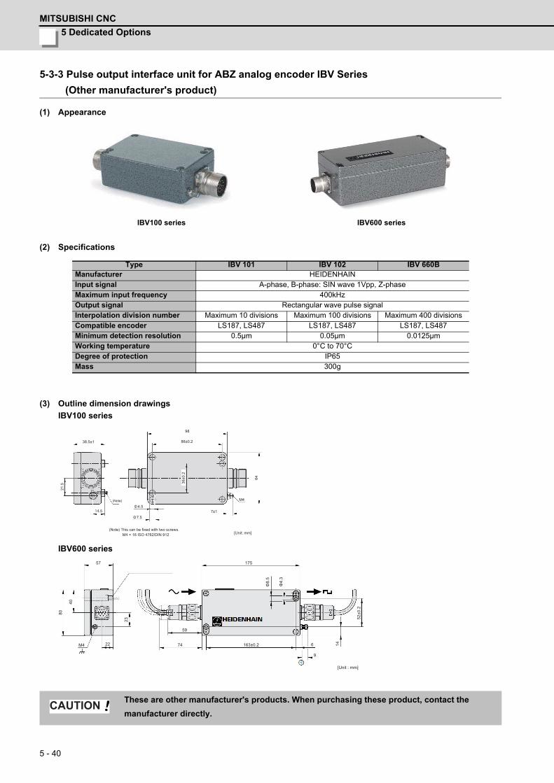
5 Dedicated Options
MITSUBISHI CNC
5 - 40
5-3-3 Pulse output interface unit for ABZ analog encoder IBV Series
(Other manufacturer's product)
(1) Appearance
(2) Specifications
(3) Outline dimension drawings
IBV100 series
IBV600 series
IBV100 series IBV600 series
Type IBV 101 IBV 102 IBV 660BManufacturer HEIDENHAINInput signal A-phase, B-phase: SIN wave 1Vpp, Z-phaseMaximum input frequency 400kHzOutput signal Rectangular wave pulse signalInterpolation division number Maximum 10 divisions Maximum 100 divisions Maximum 400 divisionsCompatible encoder LS187, LS487 LS187, LS487 LS187, LS487Minimum detection resolution 0.5μm 0.05μm 0.0125μmWorking temperature 0°C to 70°CDegree of protection IP65Mass 300g
These are other manufacturer's products. When purchasing these product, contact the
manufacturer directly.
38.5±1
98
86±0.2
36±0
.2
7±1Φ4.5
Φ7.514.5
21.5
M4
64
M4 × 16 ISO 4762/DIN 912
(Note)
(Note) This can be fixed with two screws.[Unit: mm]
52±0
.2
175
163±0.274
59
9
622
23
M4
57
40
80
Φ8.
5
Φ4.
3
14
[Unit : mm]
CAUTION
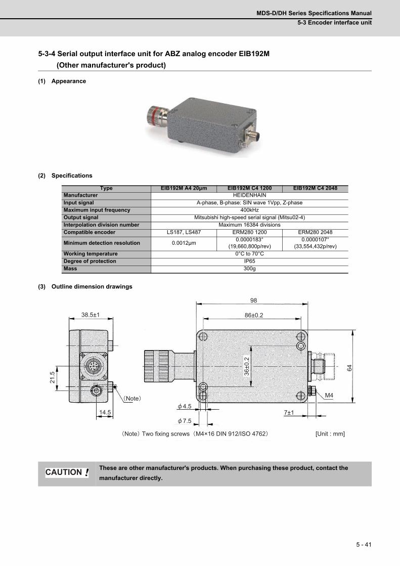
MDS-D/DH Series Specifications Manual
5-3 Encoder interface unit
5 - 41
5-3-4 Serial output interface unit for ABZ analog encoder EIB192M
(Other manufacturer's product)
(1) Appearance
(2) Specifications
(3) Outline dimension drawings
Type EIB192M A4 20μm EIB192M C4 1200 EIB192M C4 2048Manufacturer HEIDENHAINInput signal A-phase, B-phase: SIN wave 1Vpp, Z-phaseMaximum input frequency 400kHzOutput signal Mitsubishi high-speed serial signal (Mitsu02-4)Interpolation division number Maximum 16384 divisionsCompatible encoder LS187, LS487 ERM280 1200 ERM280 2048
Minimum detection resolution 0.0012μm0.0000183°
(19,660,800p/rev)0.0000107°
(33,554,432p/rev)Working temperature 0°C to 70°CDegree of protection IP65Mass 300g
These are other manufacturer's products. When purchasing these product, contact the
manufacturer directly.
21.5
14.57.5
4.5
38.5±1
98
86±0.2
7±1
64
M4
36±0
.2
Note Two fixing screws M4×16 DIN 912/ISO 4762
Note
[Unit : mm]
CAUTION
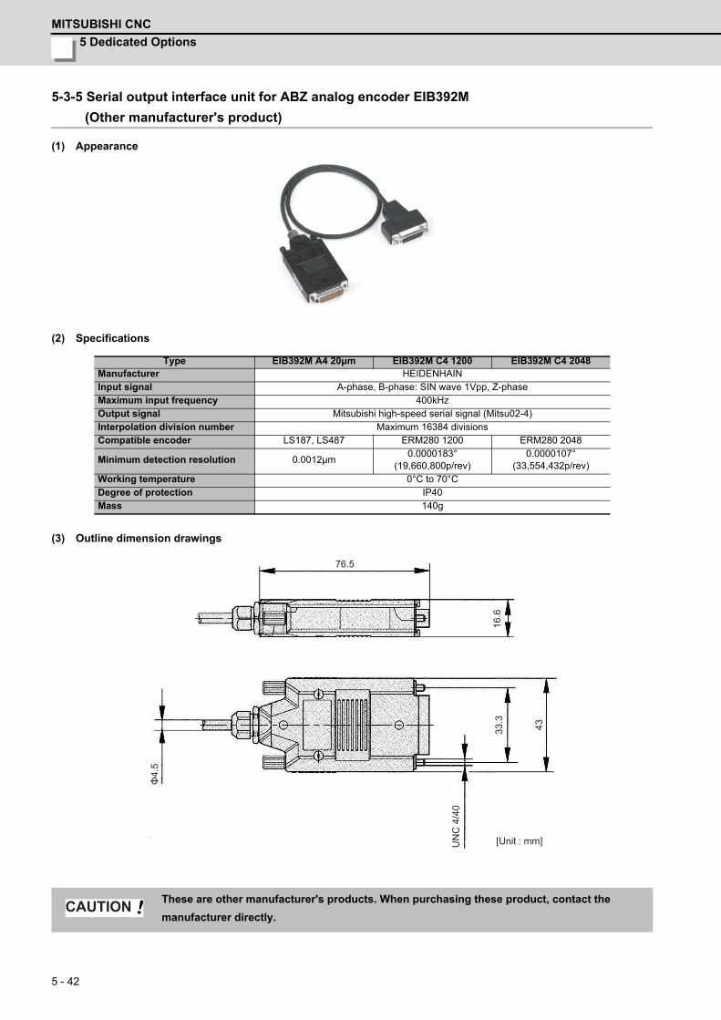
5 Dedicated Options
MITSUBISHI CNC
5 - 42
5-3-5 Serial output interface unit for ABZ analog encoder EIB392M
(Other manufacturer's product)
(1) Appearance
(2) Specifications
(3) Outline dimension drawings
Type EIB392M A4 20μm EIB392M C4 1200 EIB392M C4 2048Manufacturer HEIDENHAINInput signal A-phase, B-phase: SIN wave 1Vpp, Z-phaseMaximum input frequency 400kHzOutput signal Mitsubishi high-speed serial signal (Mitsu02-4)Interpolation division number Maximum 16384 divisionsCompatible encoder LS187, LS487 ERM280 1200 ERM280 2048
Minimum detection resolution 0.0012μm0.0000183°
(19,660,800p/rev)0.0000107°
(33,554,432p/rev)Working temperature 0°C to 70°CDegree of protection IP40Mass 140g
These are other manufacturer's products. When purchasing these product, contact the
manufacturer directly.
Φ4.
5
4333.3
16.6
UN
C 4
/40
76.5
[Unit : mm]
CAUTION
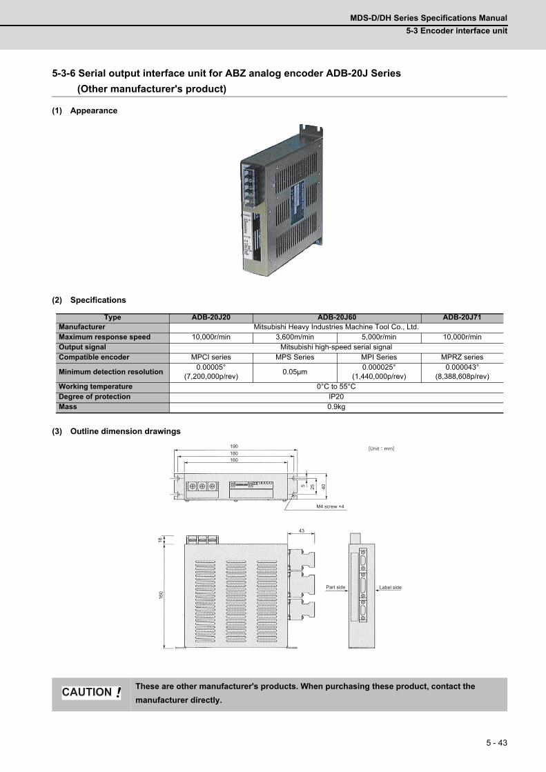
MDS-D/DH Series Specifications Manual
5-3 Encoder interface unit
5 - 43
5-3-6 Serial output interface unit for ABZ analog encoder ADB-20J Series
(Other manufacturer's product)
(1) Appearance
(2) Specifications
(3) Outline dimension drawings
Type ADB-20J20 ADB-20J60 ADB-20J71Manufacturer Mitsubishi Heavy Industries Machine Tool Co., Ltd.Maximum response speed 10,000r/min 3,600m/min 5,000r/min 10,000r/minOutput signal Mitsubishi high-speed serial signalCompatible encoder MPCI series MPS Series MPI Series MPRZ series
Minimum detection resolution0.00005°
(7,200,000p/rev)0.05μm
0.000025°(1,440,000p/rev)
0.000043°(8,388,608p/rev)
Working temperature 0°C to 55°CDegree of protection IP20Mass 0.9kg
These are other manufacturer's products. When purchasing these product, contact the
manufacturer directly.
190180160
43
1816
0
40255
[Unit:mm]
Label sidePart side
M4 screw ×4
CAUTION
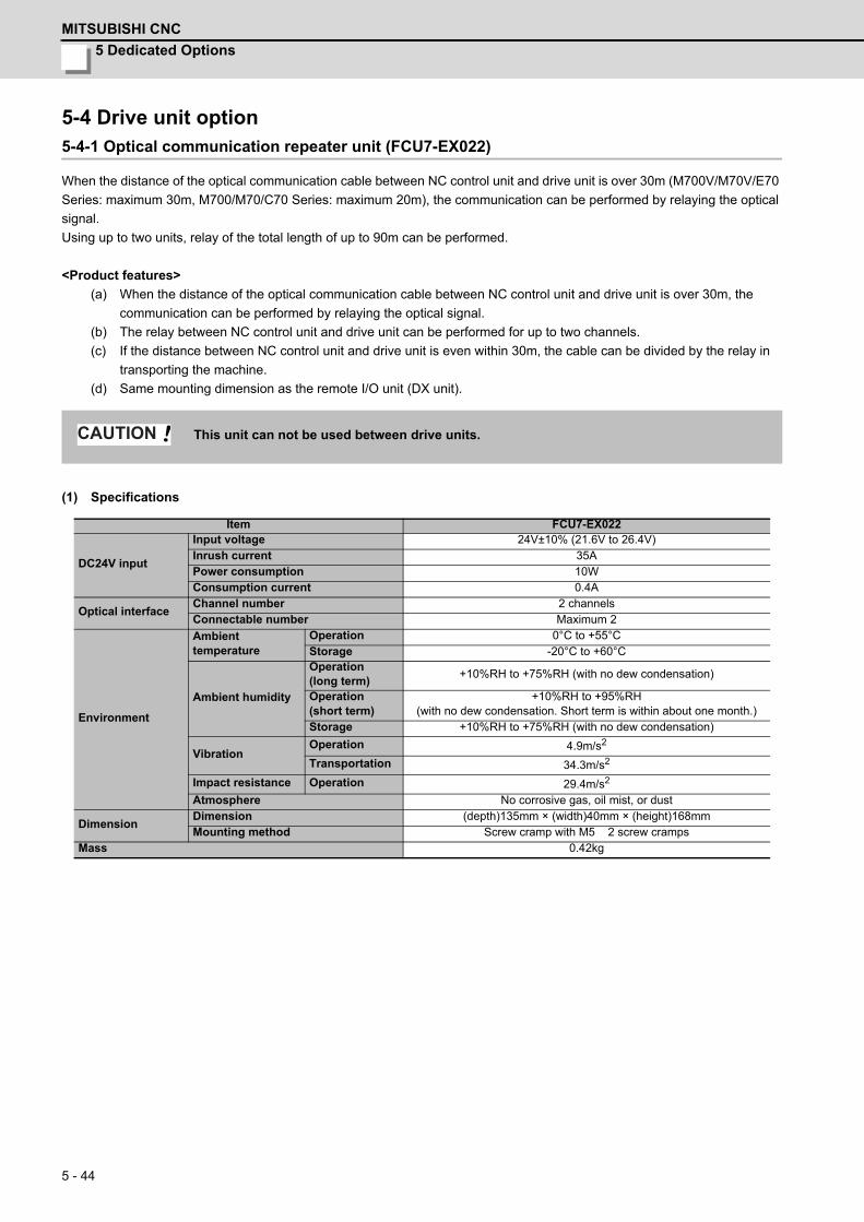
5 Dedicated Options
MITSUBISHI CNC
5 - 44
5-4 Drive unit option5-4-1 Optical communication repeater unit (FCU7-EX022)
When the distance of the optical communication cable between NC control unit and drive unit is over 30m (M700V/M70V/E70
Series: maximum 30m, M700/M70/C70 Series: maximum 20m), the communication can be performed by relaying the optical
signal.
Using up to two units, relay of the total length of up to 90m can be performed.
<Product features>
(a) When the distance of the optical communication cable between NC control unit and drive unit is over 30m, the
communication can be performed by relaying the optical signal.
(b) The relay between NC control unit and drive unit can be performed for up to two channels.
(c) If the distance between NC control unit and drive unit is even within 30m, the cable can be divided by the relay in
transporting the machine.
(d) Same mounting dimension as the remote I/O unit (DX unit).
(1) Specifications
This unit can not be used between drive units.
Item FCU7-EX022
DC24V input
Input voltage 24V±10% (21.6V to 26.4V)Inrush current 35APower consumption 10WConsumption current 0.4A
Optical interfaceChannel number 2 channelsConnectable number Maximum 2
Environment
Ambient temperature
Operation 0°C to +55°C Storage -20°C to +60°C
Ambient humidity
Operation(long term)
+10%RH to +75%RH (with no dew condensation)
Operation(short term)
+10%RH to +95%RH (with no dew condensation. Short term is within about one month.)
Storage +10%RH to +75%RH (with no dew condensation)
VibrationOperation 4.9m/s2
Transportation 34.3m/s2
Impact resistance Operation 29.4m/s2
Atmosphere No corrosive gas, oil mist, or dust
DimensionDimension (depth)135mm × (width)40mm × (height)168mmMounting method Screw cramp with M5 2 screw cramps
Mass 0.42kg
CAUTION

MDS-D/DH Series Specifications Manual
5-4 Drive unit option
5 - 45
(2) Explanation of connectors
< Connector pin layout >
Connector name Application RemarksOPT1IN,
OPT1OUT, OPT2IN,
OPT2OUT
Optical connector
DCIN DC24V Power connector
DCOUTDC24V/ Power OFF detection
output connectorRelays the PD25/27 output to NC control unit.
ACFAIL Power OFF detection connector
Relays the power OFF detection signal (ACFAIL) when sharing 24V power from PD25/PD27 for NC control unit and optical communication repeater unit.It will not be used when dedicated general-purpose power supply for optical communication repeater unit is prepared.
FG FG Faston terminal
DCIN DCOUT ACFAILPin No. Name Pin No. Name Pin No. Name Pin No. Name
1 DC24V A1 ACFAIL B1 DC24V 1 COM2 0V (RG) A2 COM B2 0V (RG) 2 ACFAIL3 FG A3 NC B3 FG
Optical communication I/F (OPT1IN, OPT1OUT,
OPT2IN, OPT2OUT)DC24V input (DCIN) DC24V output (DCOUT)
Power OFF input ACFAIL
(Terminal name:CF01)FG terminal (FG)
<Cable side connector type>(PCF type)Connector: CF-2D101-SRecommended manufacturer: Japan Aviation Electronics(POF type)Connector: PF-2D101Recommended manufacturer:Japan Aviation Electronics
<PCB side connector type>Connector: 2-178293-5Recommended manufacturer: Tyco Electronics<Cable side connector type>Connector: 2-178288-3Contact: 1-175218-5 Recommended manufacturer: Tyco Electronics
<PCB side connector type>Connector: 3-178137-5Recommended manufacturer: Tyco Electronics<Cable side connector type>Connector: 2-178127-6Contact: 1-175218-5 Recommended manufacturer: Tyco Electronics
<PCB side connector type>Connector: 53103-0230Recommended manufacturer: MOLEX<Cable side connector type>Connector: 005057-9402Contact: 0016020103Recommended manufacturer: MOLEX
<Cable side faston terminal type name>Type name: 175022-1(For AWG20-14 250 series)Recommended manufacturer: Tyco ElectronicsTerminal protection tube: 174817-2 (Yellow)
Unit side tab terminal shape(Note) The faston terminal "175022-1" of the cable side is a simple lock type. Make sure to insert until the simple lock pin is in the Φsecond hole. Firmly press the simple lock release tab when unplugging it.
1 3
A3A1
B3B1
2 1
FG
Φ2.0
5.0
6.2
0.9
0.8±0.0259.6
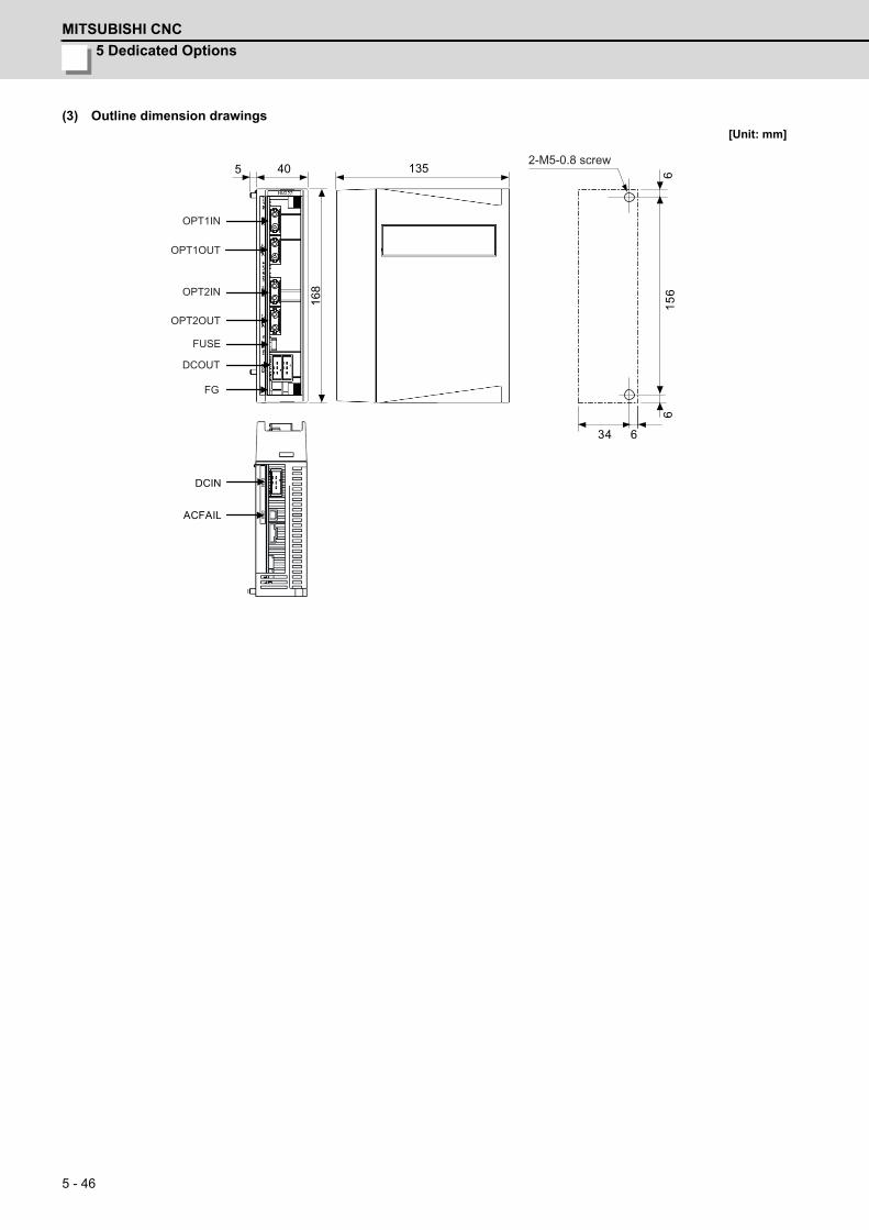
5 Dedicated Options
MITSUBISHI CNC
5 - 46
(3) Outline dimension drawings[Unit: mm]
634
135405
156
66
168
DCIN
ACFAIL
OPT1IN
DCOUT
FG
FUSE
OPT2IN
OPT1OUT
OPT2OUT
2-M5-0.8 screw

MDS-D/DH Series Specifications Manual
5-4 Drive unit option
5 - 47
5-4-2 DC connection bar
When connecting a large capacity drive unit with L+L- terminal of power supply unit, DC connection bar is required. In use of
the following large capacity drive units, use a dedicated DC connection bar. The DC connection bar to be used depends on
the connected power supply, so make a selection according to the following table.
(1) Outline dimension drawings[Unit:mm]
(Note) D-BAR-A1010 is a set of two DC connection bars.
(Note) DH-BAR-A0606 is a set of two DC connection bars.
Series Large capacity drive unit Power supply unit Required connection bar
MDS-D
MDS-D-SP-400MDS-D-SP-640
MDS-D-CV-300MDS-D-CV-370MDS-D-CV-450
D-BAR-B1006
MDS-D-SP-400MDS-D-SP-640
MDS-D-CV-550D-BAR-A1010(Two-parts set)
MDS-DH
MDS-DH-SP-200MDS-DH-SP-320MDS-DH-SP-480
MDS-DH-CV-550MDS-DH-CV-750
DH-BAR-A0606(Two-parts set)
MDS-DH-V1-200MDS-DH-SP-200MDS-DH-SP-320
MDS-DH-CV-300MDS-DH-CV-370MDS-DH-CV-450
DH-BAR-B0606
MDS-DH-V1-200 MDS-DH-CV-185 DH-BAR-C0606
D-BAR-A1010 D-BAR-B1006
DH-BAR-A0606 DH-BAR-B0606
DH-BAR-C0606
Always install a large capacity drive unit in the left side of power supply unit, and connect with
DC connection bar.
25
12.5
57.5
89
17 14.5
12 DIA.24
12
t3
138 6.5
2537
25
12 DIA.
7
24
15.5
15.5
14
67
46.5
7
14
12
7 DIA.
8.5
7
14
t3
15.5
133.5
24
7 DIA. 14
7
15.5
24
14
7
7 DIA.
24
93.5
2415
.515
.5
POINT
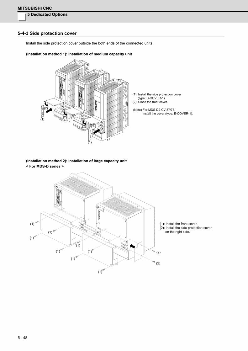
5 Dedicated Options
MITSUBISHI CNC
5 - 48
5-4-3 Side protection cover
Install the side protection cover outside the both ends of the connected units.
(Installation method 1): Installation of medium capacity unit
(Installation method 2): Installation of large capacity unit
< For MDS-D series >
(1): Install the side protection cover (type: D-COVER-1).(2): Close the front cover.
(1)
(1)
(2)
(2)
(2) (Note) For MDS-D2-CV-37/75, install the cover (type: E-COVER-1).
(1)
(2)
(1)
(1)
(1)
(1)
(1)
(1)
(1)
(2)
(1): Install the front cover.(2): Install the side protection cover on the right side.
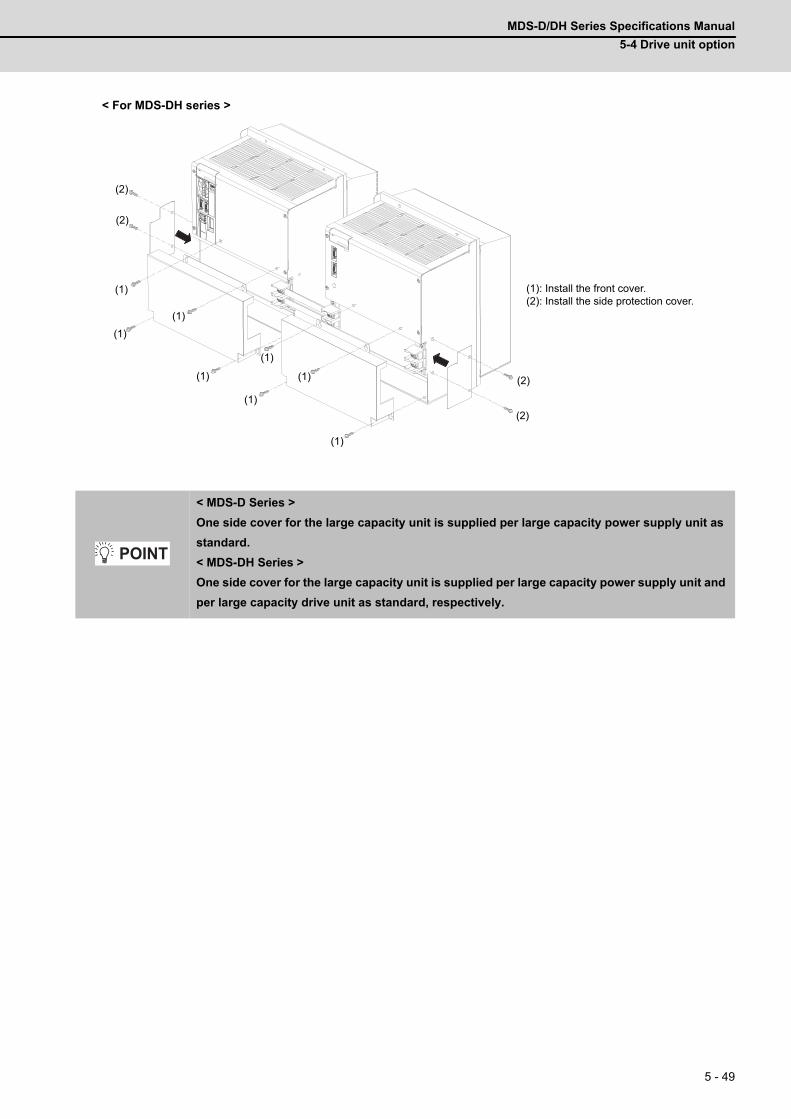
MDS-D/DH Series Specifications Manual
5-4 Drive unit option
5 - 49
< For MDS-DH series >
< MDS-D Series >
One side cover for the large capacity unit is supplied per large capacity power supply unit as
standard.
< MDS-DH Series >
One side cover for the large capacity unit is supplied per large capacity power supply unit and
per large capacity drive unit as standard, respectively.
(1)
(2)
(1)
(1)
(1)
(1)
(1)
(1)
(1)
(2)
(1): Install the front cover.(2): Install the side protection cover.
(2)
(2)
POINT
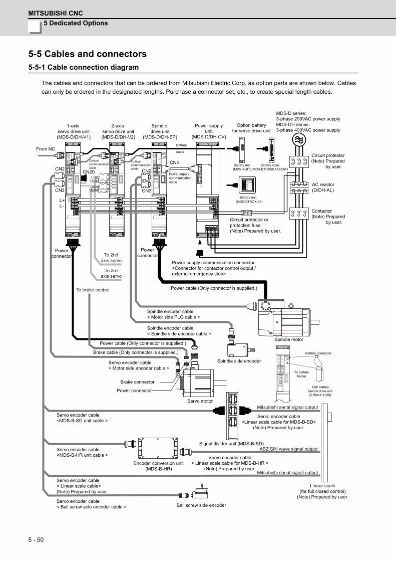
5 Dedicated Options
MITSUBISHI CNC
5 - 50
5-5 Cables and connectors5-5-1 Cable connection diagram
The cables and connectors that can be ordered from Mitsubishi Electric Corp. as option parts are shown below. Cables
can only be ordered in the designated lengths. Purchase a connector set, etc., to create special length cables.
L+L-
CN3
CN2 CN2
CN3
CN20
CN4
(MDS-BTBOX-36)
DOCOM DO(ALM) LG +5V LG BT
CN2LCN3L
CN2MCN3M
Powerconnector
From NC
1-axis servo drive unit(MDS-D/DH-V1)
2-axis servo drive unit(MDS-D/DH-V2)
Spindle drive unit
(MDS-D/DH-SP)
Power supplyunit
(MDS-D/DH-CV)
Option batteryfor servo drive unit
MDS-D series: 3-phase 200VAC power supplyMDS-DH series: 3-phase 400VAC power supply
Circuit protector(Note) Prepared by user.
AC reactor(D/DH-AL)
Contactor(Note) Prepared by user.
Circuit protector orprotection fuse(Note) Prepared by user.
Power supply communication connector<Connector for contactor control output /external emergency stop>
Powerconnector
Opticalcommunicationcable
Opticalcommunicationcable
Battery
cable
Power supply communicationcable
Battery unit(MDS-A-BT)
Battery case(MDS-BTCASE+A6BAT)
Battery unit
Power cable (Only connector is supplied.)
Spindle encoder cable< Motor side PLG cable >
Spindle encoder cable< Spindle side encoder cable >
Power cable (Only connector is supplied.)
Servo encoder cable< Motor side encoder cable >
Brake cable (Only connector is supplied.)
Brake connector
Power connector
Servo motor
Servo encoder cable<MDS-B-SD unit cable >
Spindle side encoder
Signal divider unit (MDS-B-SD)
Spindle motor
Servo encoder cable<Linear scale cable for MDS-B-SD>
(Note) Prepared by user.
Battery connector
To batteryholder
Cell batterybuilt in drive unit(ER6V-C119B)
Servo encoder cable< Linear scale cable for MDS-B-HR >
(Note) Prepared by user.
Linear scale(for full closed control)
(Note) Prepared by user.
Ball screw side encoder
Encoder conversion unit(MDS-B-HR)
Servo encoder cable<MDS-B-HR unit cable >
Servo encoder cable< Linear scale cable> (Note) Prepared by user.
Servo encoder cable< Ball screw side encoder cable >
To brake control
To 3rd axis servo
To 2nd axis servo
Brake connector
ABZ SIN wave signal output
Mitsubishi serial signal output
Mitsubishi serial signal output
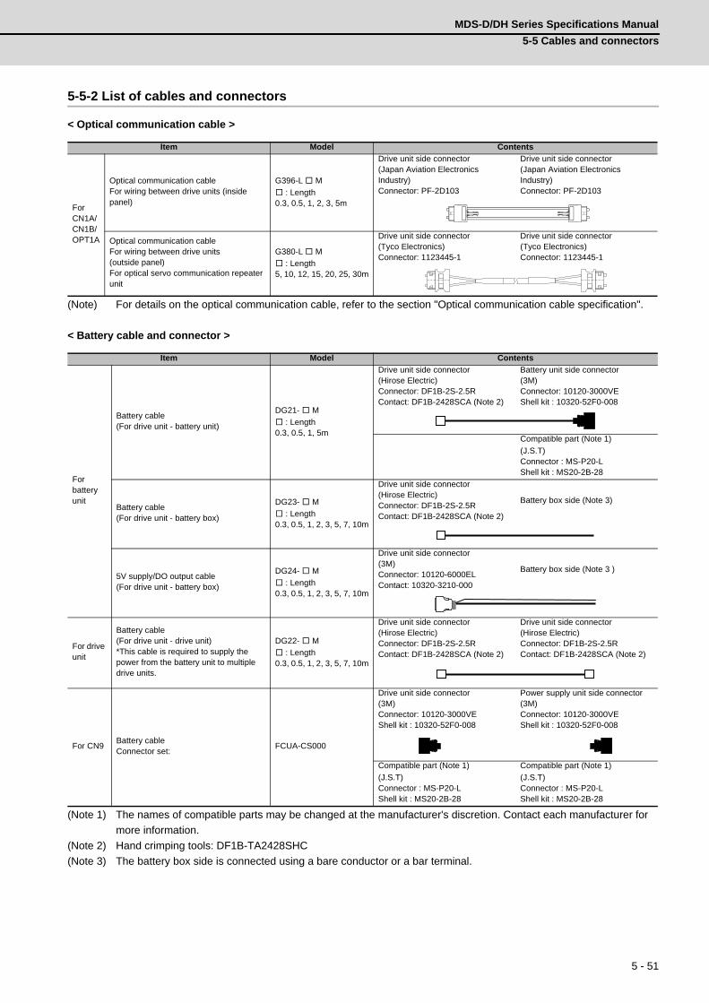
MDS-D/DH Series Specifications Manual
5-5 Cables and connectors
5 - 51
5-5-2 List of cables and connectors
< Optical communication cable >
(Note) For details on the optical communication cable, refer to the section "Optical communication cable specification".
< Battery cable and connector >
(Note 1) The names of compatible parts may be changed at the manufacturer's discretion. Contact each manufacturer for
more information.
(Note 2) Hand crimping tools: DF1B-TA2428SHC
(Note 3) The battery box side is connected using a bare conductor or a bar terminal.
Item Model Contents
For CN1A/CN1B/OPT1A
Optical communication cableFor wiring between drive units (inside panel)
G396-L M
: Length0.3, 0.5, 1, 2, 3, 5m
Drive unit side connector(Japan Aviation Electronics Industry)Connector: PF-2D103
Drive unit side connector(Japan Aviation Electronics Industry)Connector: PF-2D103
Optical communication cableFor wiring between drive units (outside panel)For optical servo communication repeater unit
G380-L M
: Length5, 10, 12, 15, 20, 25, 30m
Drive unit side connector(Tyco Electronics)Connector: 1123445-1
Drive unit side connector(Tyco Electronics)Connector: 1123445-1
Item Model Contents
For battery unit
Battery cable(For drive unit - battery unit)
DG21- M
: Length0.3, 0.5, 1, 5m
Drive unit side connector(Hirose Electric)Connector: DF1B-2S-2.5RContact: DF1B-2428SCA (Note 2)
Battery unit side connector(3M)Connector: 10120-3000VEShell kit : 10320-52F0-008
Compatible part (Note 1)
(J.S.T)Connector : MS-P20-LShell kit : MS20-2B-28
Battery cable(For drive unit - battery box)
DG23- M
: Length0.3, 0.5, 1, 2, 3, 5, 7, 10m
Drive unit side connector(Hirose Electric)Connector: DF1B-2S-2.5RContact: DF1B-2428SCA (Note 2)
Battery box side (Note 3)
5V supply/DO output cable (For drive unit - battery box)
DG24- M
: Length0.3, 0.5, 1, 2, 3, 5, 7, 10m
Drive unit side connector(3M)Connector: 10120-6000ELContact: 10320-3210-000
Battery box side (Note 3 )
For drive unit
Battery cable(For drive unit - drive unit)*This cable is required to supply the power from the battery unit to multiple drive units.
DG22- M
: Length0.3, 0.5, 1, 2, 3, 5, 7, 10m
Drive unit side connector(Hirose Electric)Connector: DF1B-2S-2.5RContact: DF1B-2428SCA (Note 2)
Drive unit side connector(Hirose Electric)Connector: DF1B-2S-2.5RContact: DF1B-2428SCA (Note 2)
For CN9Battery cableConnector set:
FCUA-CS000
Drive unit side connector(3M)Connector: 10120-3000VEShell kit : 10320-52F0-008
Power supply unit side connector (3M)Connector: 10120-3000VEShell kit : 10320-52F0-008
Compatible part (Note 1) Compatible part (Note 1)
(J.S.T)Connector : MS-P20-LShell kit : MS20-2B-28
(J.S.T)Connector : MS-P20-LShell kit : MS20-2B-28

5 Dedicated Options
MITSUBISHI CNC
5 - 52
< Power supply communication cable and connector >
(Note) The names of compatible parts may be changed at the manufacturer's discretion. Contact each manufacturer for
more information.
< Optical communication repeater unit >
(Note 1) Hand crimping tools: 91558-1
(Note 2) Hand crimping tools: 91557-1
(Note 3) Hand crimping tools: 57036-5000
Item Model Contents
For CN4/9 Power supply communication cable
SH21Length:0.35, 0.5, 0.7, 1, 1.5, 2,2.5,3, 3.5, 4, 4.5, 5, 6, 7, 8, 9,10, 15, 20, 30m
Drive unit side connector(3M)Connector: 10120-6000ELShell kit : 10320-3210-000
Power supply unit side connector (3M)Connector: 10120-6000ELShell kit : 10320-3210-000
For CN4/9Power supply communication cable connector set
FCUA-CS000
Drive unit side connector(3M)Connector: 10120-3000VEShell kit : 10320-52F0-008
Power supply unit side connector (3M)Connector: 10120-3000VEShell kit : 10320-52F0-008
Compatible part (Note) Compatible part (Note)
(J.S.T)Connector : MS-P20-LShell kit : MS20-2B-28
(J.S.T)Connector : MS-P20-LShell kit : MS20-2B-28
For CN23Contactor control output / external emergency stop for connector
CNU23S(AWG14)
Power supply unit side connector(DDK)Connector: DK-3200M-06RXYContact: DK-3REC2LLP1-100
Item Model Contents
ForOPT1/2
Optical communication cableFor wiring between drive unit and optical communication repeater unit/For wiring between optical communication repeater units
G380-L M
: Length5, 10, 12, 15, 20, 25, 30m
Drive unit side/Optical communication repeater unit side connector(Tyco Electronics)Connector: 1123445-1
Optical communication repeater unit side connector(Tyco Electronics)Connector: 1123445-1
ForDCIN
For optical communication repeater unitDC24V power cable
F070
: Length0.5, 1.5, 3, 5, 8, 10, 15, 20m
DC24V power side terminal(J.S.T.)Crimp terminal: V1.25-3 or V1.25-4 × 2
Optical communication repeater unit side connector(Tyco Electronics)Connector: 2-178288-3Contact: 1-175218-5 × 3 (Note 1)
ForDCIN/
ACFAIL
For optical communication repeater unit/For connecting Mitsubishi power unit PD25, PD27DC24V power cable(power OFF detection)
F110
: Length0.5, 1.5, 3, 5, 8, 10, 15m
DC24V power side connector(Tyco Electronics)Connector: 3-178127-6Contact: 1-175218-5 (for AWG16) × 3 (Note 1)1-175217-5 (for AWG22) × 2 (Note 2)
Optical communication repeater unit side connector< DCIN >(Tyco Electronics) Connector: 2-178288-3 Contact: 1-175218-5 × 3 (Note 1)< ACFAIL (CF01) >(MOLEX) 005057-9402 0016020103 × 2 (Note 3)
Y
DCIN
Y
DCOUT
DCIN
CF01
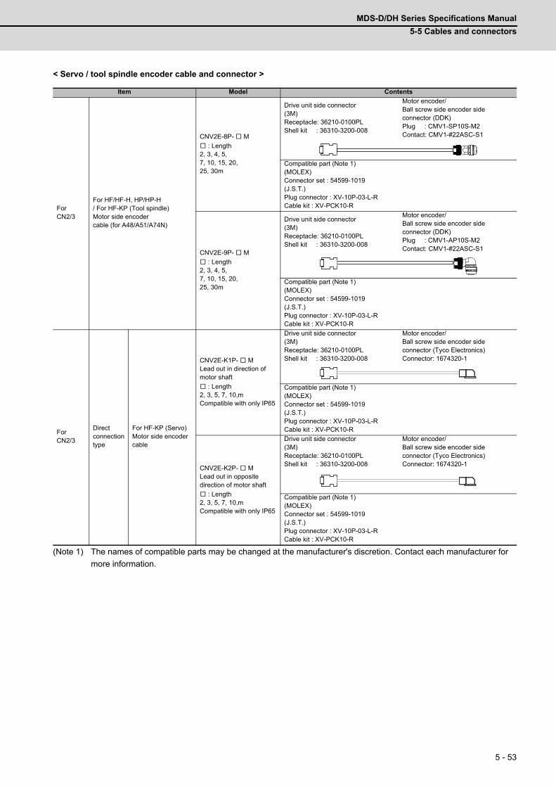
MDS-D/DH Series Specifications Manual
5-5 Cables and connectors
5 - 53
< Servo / tool spindle encoder cable and connector >
(Note 1) The names of compatible parts may be changed at the manufacturer's discretion. Contact each manufacturer for
more information.
Item Model Contents
For CN2/3
For HF/HF-H, HP/HP-H/ For HF-KP (Tool spindle) Motor side encoder cable (for A48/A51/A74N)
CNV2E-8P- M
: Length2, 3, 4, 5,7, 10, 15, 20,25, 30m
Drive unit side connector(3M)Receptacle: 36210-0100PLShell kit : 36310-3200-008
Motor encoder/Ball screw side encoder side connector (DDK)Plug : CMV1-SP10S-M2Contact: CMV1-#22ASC-S1
Compatible part (Note 1)(MOLEX)Connector set : 54599-1019(J.S.T.) Plug connector : XV-10P-03-L-RCable kit : XV-PCK10-R
CNV2E-9P- M
: Length2, 3, 4, 5,7, 10, 15, 20,25, 30m
Drive unit side connector(3M)Receptacle: 36210-0100PLShell kit : 36310-3200-008
Motor encoder/Ball screw side encoder side connector (DDK)Plug : CMV1-AP10S-M2Contact: CMV1-#22ASC-S1
Compatible part (Note 1)(MOLEX)Connector set : 54599-1019(J.S.T.) Plug connector : XV-10P-03-L-RCable kit : XV-PCK10-R
For CN2/3
Direct connectiontype
For HF-KP (Servo)Motor side encoder cable
CNV2E-K1P- MLead out in direction of motor shaft
: Length2, 3, 5, 7, 10,mCompatible with only IP65
Drive unit side connector(3M)Receptacle: 36210-0100PLShell kit : 36310-3200-008
Motor encoder/Ball screw side encoder side connector (Tyco Electronics)Connector: 1674320-1
Compatible part (Note 1)(MOLEX)Connector set : 54599-1019(J.S.T.) Plug connector : XV-10P-03-L-RCable kit : XV-PCK10-R
CNV2E-K2P- MLead out in opposite direction of motor shaft
: Length2, 3, 5, 7, 10,mCompatible with only IP65
Drive unit side connector(3M)Receptacle: 36210-0100PLShell kit : 36310-3200-008
Motor encoder/Ball screw side encoder side connector (Tyco Electronics)Connector: 1674320-1
Compatible part (Note 1)(MOLEX)Connector set : 54599-1019(J.S.T.) Plug connector : XV-10P-03-L-RCable kit : XV-PCK10-R

5 Dedicated Options
MITSUBISHI CNC
5 - 54
(Note 1) When using cable of 15m or longer, use relay cable.
(Note 2) The names of compatible parts may be changed at the manufacturer's discretion. Contact each manufacturer for
more information.
Item Model Contents
For CN2/3
Relaytype(Note 1)
For HF-KP (Servo)Motor side encoder relay cable(motor side)
CNV22J-K1P-0.3MLead out in direction of motor shaftLength: 0.3mCompatible with only IP65
Drive unit side connector(DDK)Plug: CM10-CR10P-M
Motor encoder/Ball screw side encoder side connector (Tyco Electronics)Plug : 1747464-1Contact: 1674335-4
CNV22J-K2P-0.3MLead out in opposite direction of motor shaft Length: 0.3mCompatible with only IP65
Drive unit side connector(DDK)Plug: CM10-CR10P-M
Motor encoder/Ball screw side encoder side connector (Tyco Electronics)Plug : 1747464-1Contact: 1674335-4
For HF-KP (Servo)Motor side encoder relay cable(Drive unit side)
CNV2E-8P- M
: Length15, 20, 25, 30m
Drive unit side connector(3M)Receptacle: 36210-0100PLShell kit : 36310-3200-008
Motor encoder/Ball screw side encoder side connector (DDK)Plug : CMV1-SP10S-M2Contact: CMV1-#22ASC-S1
Compatible part (Note 2)(MOLEX)Connector set : 54599-1019(J.S.T.) Plug connector : XV-10P-03-L-RCable kit : XV-PCK10-R
For motor encoder/ Ball screw side encoder
Motor side encoder connector/Ball screw side encoder connector
CNE10-R10S(9)Applicable cable outlineΦ6.0 to 9.0mm
Motor encoder/Ball screw side encoder side connector (DDK)Plug : CMV1-SP10S-M2Contact: CMV1-#22ASC-S1
CNE10-R10L(9)Applicable cable outlineΦ6.0 to 9.0mm
Motor encoder/Ball screw side encoder side connector (DDK)Plug : CMV1-AP10S-M2Contact: CMV1-#22ASC-S1
CN3 MDS-B-HR unit cable
CNV2E-HP- M
: Length2, 3, 4, 5,7, 10, 15, 20,25, 30m
Drive unit side connector(3M)Receptacle: 36210-0100PLShell kit : 36310-3200-008
MDS-B-HR unit side connector(Hirose Electric)Plug : RM15WTPZ-8S(71)Clamp: JR13WCCA-10(72)
Compatible part (Note 2)(MOLEX)Connector set : 54599-1019(J.S.T.)Plug connector : XV-10P-03-L-RCable kit : XV-PCK10-R
For MDS-B-HR unit
MDS-B-HR connector(For CON1,2: 1)(For CON3: 1)
CNEHRS(10)Applicable cable outlineΦ8.5 to 11mm
MDS-B-HR unit side connector(Hirose Electric)Plug : RM15WTPZ-8S(71) (for CON1, 2) RM15WTPZ-12P(71) (for CON3)Clamp: JR13WCCA-10(72) (10)

MDS-D/DH Series Specifications Manual
5-5 Cables and connectors
5 - 55
(Note 1) The names of compatible parts may be changed at the manufacturer's discretion. Contact each manufacturer for
more information.
Item Model Contents
CN3 MDS-B-SD unit cable
CNV2E-D- M
: Length2, 3, 4, 5,7, 10, 15, 20,25, 30m
Drive unit side connector(3M)Receptacle: 36210-0100PLShell kit : 36310-3200-008
MDS-B-SD unit side connector(3M)Connector: 10120-3000VEShell kit : 10320-52F0-008
Compatible part (Note 1)(MOLEX)Connector set : 54599-1019(J.S.T.) Plug connector : XV-10P-03-L-RCable kit : XV-PCK10-R
Compatible part (Note 1)
(MOLEX)Connector: MS-P20-LShell kit: MS20-2B-28
For MDS-B-SD unit
MDS-B-SD connector(Two-piece set)
FCUA-CS000
MDS-B-SD unit side connector(3M)Connector: 10120-3000VEShell kit : 10320-52F0-008
MDS-B-SD unit side connector(J.S.T)Connector: 10120-3000VEShell kit : 10320-52F0-008
Compatible part (Note 1) Compatible part (Note 1)
(J.S.T.)Connector: MS-P20-LShell kit: MS20-2B-28
(J.S.T.)Connector: MS-P20-LShell kit: MS20-2B-28
For CN2/3
Encoder connector CNU2S(AWG18)
Drive unit side connector(3M)Receptacle: 36210-0100PLShell kit : 36310-3200-008
Compatible part (Note 1)(MOLEX)Connector set : 54599-1019(J.S.T.) Plug connector : XV-10P-03-L-RCable kit : XV-PCK10-R
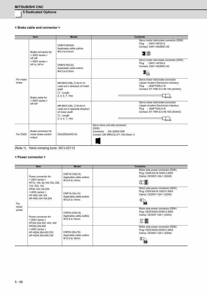
5 Dedicated Options
MITSUBISHI CNC
5 - 56
< Brake cable and connector >
(Note 1) Hand crimping tools: 357J-22113
< Power connector >
Item Model Contents
For motor brake
Brake connector for< 200V series >HF,HP< 400V series >HF-H, HP-H
CNB10-R2S(6)Applicable cable outlineΦ4.0 to 6.0mm
Servo motor side brake connector (DDK)Plug : CMV1-SP2S-SContact: CMV1-#22BSC-S2
CNB10-R2L(6)Applicable cable outlineΦ4.0 to 6.0mm
Servo motor side brake connector (DDK)Plug : CMV1-AP2S-SContact: CMV1-#22BSC-S2
Brake cable for< 200V series >HF-KP
MR-BKS1CBL M-A1-HLead out in direction of motor shaft
: Length2, 3, 5, 7, 10m
Servo motor side brake connector(Japan Aviation Electronics Industry)Plug : JN4FT02SJ1-RContact: ST-TMH-S-C1B-100-(A534G)
MR-BKS1CBL M-A2-HLead out in opposite direction of motor shaft
: Length2, 3, 5, 7, 10m
Servo motor side brake connector(Japan Aviation Electronics Industry)Plug : JN4FT02SJ1-RContact: ST-TMH-S-C1B-100-(A534G)
For CN20Brake connector for motor brake control output
CNU20S(AWG14)
Servo drive unit side connector(DDK)Connector : DK-3200S-03RContact: DK-3REC2LLP1-100 (Note 1)
Item Model Contents
For motorpower
Power connector for< 200V series >HF75, 105, 54,104,154, 224, 123, 223, 142HP54,104,154,224< 400V series >HF-H54,104,154HP-H54,104,154,224
CNP18-10S(14)Applicable cable outlineΦ10.5 to 14mm
Motor side power connector (DDK)Plug: CE05-6A18-10SD-C-BSSClamp: CE3057-10A-1 (D240)
CNP18-10L(14)Applicable cable outlineΦ10.5 to 14mm
Motor side power connector (DDK)Plug: CE05-8A18-10SD-C-BASClamp: CE3057-10A-1 (D240)
Power connector for< 200V series >HF204,354,303, 453, 302HP204,354,454< 400V series >HF-H204,354,453,703HP-H204,354,454,704
CNP22-22S(16)Applicable cable outlineΦ12.5 to 16mm
Motor side power connector (DDK)Plug: CE05-6A22-22SD-C-BSSClamp: CE3057-12A-1 (D240)
CNP22-22L(16)Applicable cable outlineΦ12.5 to 16mm
Motor side power connector (DDK)Plug: CE05-8A22-22SD-C-BASClamp: CE3057-12A-1 (D240)
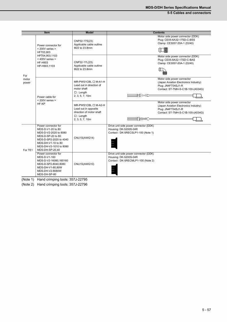
MDS-D/DH Series Specifications Manual
5-5 Cables and connectors
5 - 57
(Note 1) Hand crimping tools: 357J-22795
(Note 2) Hand crimping tools: 357J-22796
Item Model Contents
For motorpower
Power connector for< 200V series >HF703,903HP704,903,1103< 400V series >HF-H903HP-H903,1103
CNP32-17S(23)Applicable cable outlineΦ22 to 23.8mm
Motor side power connector (DDK)Plug: CE05-6A32-17SD-C-BSSClamp: CE3057-20A-1 (D240)
CNP32-17L(23)Applicable cable outlineΦ22 to 23.8mm
Motor side power connector (DDK)Plug: CE05-8A32-17SD-C-BASClamp: CE3057-20A-1 (D240)
Power cable for< 200V series >HF-KP
MR-PWS1CBL M-A1-HLead out in direction of motor shaft
: Length2, 3, 5, 7, 10m
Motor side power connector(Japan Aviation Electronics Industry)Plug: JN4FT04SJ1-RContact: ST-TMH-S-C1B-100-(A534G)
MR-PWS1CBL M-A2-HLead out in opposite direction of motor shaft
: Length2, 3, 5, 7, 10m
Motor side power connector(Japan Aviation Electronics Industry)Plug: JN4FT04SJ1-RContact: ST-TMH-S-C1B-100-(A534G)
For TE1
Power connector forMDS-D-V1-20 to 80MDS-D-V2-2020 to 8080MDS-D-SP-20 to 80MDS-D-SP2-2020 to 4040MDS-DH-V1-10 to 80MDS-DH-V2-1010 to 8080MDS-DH-SP-20,40
CNU1S(AWG14)
Drive unit side power connector (DDK)Housing: DK-5200S-04RContact : DK-5RECSLP1-100 (Note 1)
Power connector forMDS-D-V1-160MDS-D-V2-16080,160160MDS-D-SP2-8040,8080MDS-DH-V1-80,80WMDS-DH-V2-8080WMDS-DH-SP-80
CNU1S(AWG10)
Drive unit side power connector (DDK)Housing: DK-5200S-04RContact : DK-5RECMLP1-100 (Note 2)
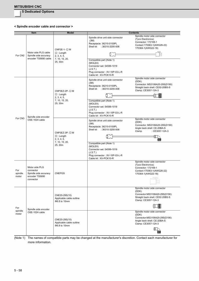
5 Dedicated Options
MITSUBISHI CNC
5 - 58
< Spindle encoder cable and connector >
(Note 1) The names of compatible parts may be changed at the manufacturer's discretion. Contact each manufacturer for
more information.
Item Model Contents
For CN2Motor side PLG cableSpindle side accuracy encoder TS5690 cable
CNP2E-1- M
: Length2, 3, 4, 5,7, 10, 15, 20,25, 30m
Spindle drive unit side connector (3M)Receptacle: 36210-0100PLShell kit : 36310-3200-008
Spindle motor side connector(Tyco Electronics)Connector: 172169-1Contact:170363-1(AWG26-22)170364-1(AWG22-18)
Compatible part (Note 1)(MOLEX)Connector set: 54599-1019(J.S.T.) Plug connector : XV-10P-03-L-RCable kit : XV-PCK10-R
For CN3Spindle side encoder OSE-1024 cable
CNP3EZ-2P- M
: Length2, 3, 4, 5,7, 10, 15, 20,25, 30m
Spindle drive unit side connector (3M)Receptacle: 36210-0100PLShell kit : 36310-3200-008
Spindle motor side connector (DDK)Connector: MS3106A20-29S(D190)Straight back shell: CE02-20BS-SClamp: CE3057-12A-3
Compatible part (Note 1)(MOLEX)Connector set: 54599-1019(J.S.T.)Plug connector : XV-10P-03-L-RCable kit : XV-PCK10-R
CNP3EZ-3P- M
: Length2, 3, 4, 5,7, 10, 15, 20,25, 30m
Spindle drive unit side connector (3M)Receptacle: 36210-0100PLShell kit : 36310-3200-008
Spindle motor side connector (DDK)Connector: MS3106A20-29S(D190)Angle back shell: CE-20BA-SClamp : CE3057-12A-3
Compatible part (Note 1)(MOLEX)Connector set: 54599-1019(J.S.T.) Plug connector : XV-10P-03-L-RCable kit : XV-PCK10-R
For spindle motor
Motor side PLG connectorSpindle side accuracy encoder TS5690 connector
CNEPGS
Spindle motor side connector(Tyco Electronics)Connector: 172169-1Contact:170363-1(AWG26-22)170364-1(AWG22-18)
For spindle motor
Spindle side encoder OSE-1024 cable
CNE20-29S(10)Applicable cable outlineΦ6.8 to 10mm
Spindle motor side connector (DDK)Connector:MS3106A20-29S(D190)Straight back shell: CE02-20BS-SClamp: CE3057-12A-3
CNE20-29S(10)Applicable cable outlineΦ6.8 to 10mm
Spindle motor side connector (DDK)Connector:MS3106A20-29S(D190)Angle back shell: CE-20BA-SClamp: CE3057-12A-3

MDS-D/DH Series Specifications Manual
5-5 Cables and connectors
5 - 59
(Note 1) The names of compatible parts may be changed at the manufacturer's discretion. Contact each manufacturer for
more information.
< Contact information >
Japan Aviation Electronics Industry, Limited: http://www.jae.com/en/index.html
HIROSE ELECTRIC CO., LTD.: http://www.hirose.com/
3M: http://www.3m.com/
J.S.T. Mfg. Co., Ltd.: http://www.jst-mfg.com/index_e.php
DDK Ltd.: http://www.ddknet.co.jp/English/index.html
Tyco Electronics Japan G.K.: http://www.te.com/en/home.html
Molex Ltd.: http://www.molex.com/
Item Model Contents
For CN2/3
Spindle encoder drive unit side connector
CNU2S(AWG18)
Spindle drive unit side connector (3M)Receptacle: 36210-0100PLShell kit : 36310-3200-008
Compatible part (Note 1)(MOLEX)Connector set: 54599-1019(J.S.T.) Plug connector : XV-10P-03-L-RCable kit : XV-PCK10-R
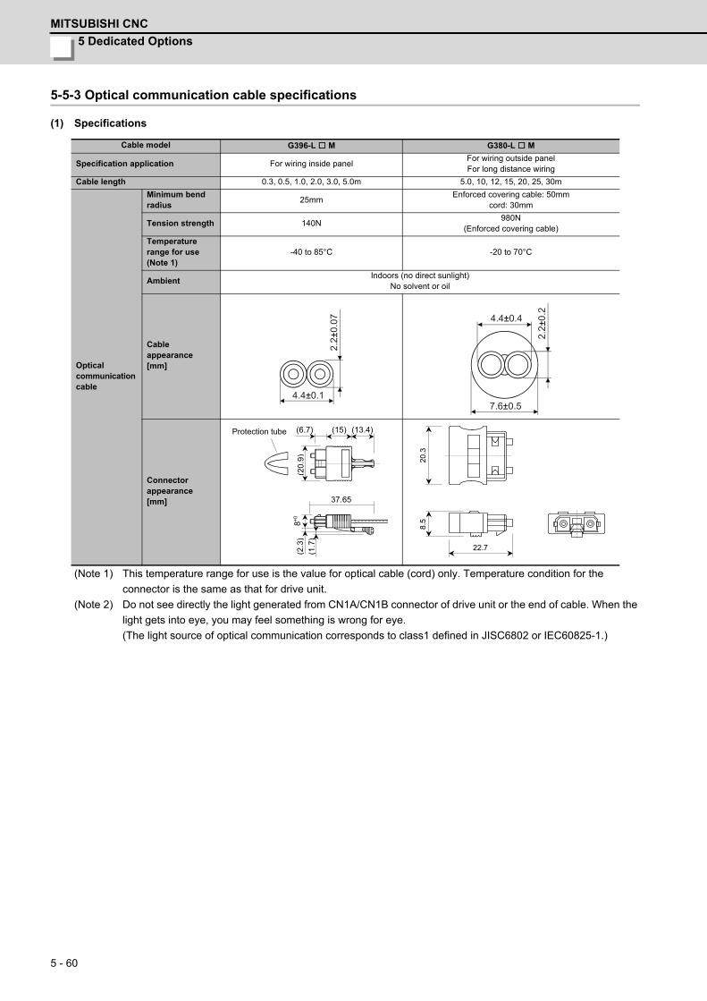
5 Dedicated Options
MITSUBISHI CNC
5 - 60
5-5-3 Optical communication cable specifications
(1) Specifications
(Note 1) This temperature range for use is the value for optical cable (cord) only. Temperature condition for the
connector is the same as that for drive unit.
(Note 2) Do not see directly the light generated from CN1A/CN1B connector of drive unit or the end of cable. When the
light gets into eye, you may feel something is wrong for eye.
(The light source of optical communication corresponds to class1 defined in JISC6802 or IEC60825-1.)
Cable model G396-L M G380-L M
Specification application For wiring inside panelFor wiring outside panelFor long distance wiring
Cable length 0.3, 0.5, 1.0, 2.0, 3.0, 5.0m 5.0, 10, 12, 15, 20, 25, 30m
Optical communication cable
Minimum bend radius
25mmEnforced covering cable: 50mm
cord: 30mm
Tension strength 140N980N
(Enforced covering cable)
Temperature range for use (Note 1)
-40 to 85°C -20 to 70°C
AmbientIndoors (no direct sunlight)
No solvent or oil
Cable appearance[mm]
Connector appearance[mm]
2.2±
0.07
4.4±0.17.6±0.5
4.4±0.4
2.2±
0.2
(13.4) (15) (6.7)
(20.
9)(2
.3)
(1
.7)
8+0
37.65
Protection tube
22.7
8.5
20
.3

MDS-D/DH Series Specifications Manual
5-5 Cables and connectors
5 - 61
(2) Cautions for using optical communication cable
Optical communication cable is made from optical fiber. If optical fiber is added a power such as a major shock, lateral
pressure, haul, sudden bending or twist, its inside distorts or breaks, and optical transmission will not be available.
Especially, as optical fiber for G396-LM is made of synthetic resin, it melts down if being left near the fire or high
temperature. Therefore, do not make it touched the part, which becomes high temperature, such as radiator or
regenerative brake option of drive unit.
Read described item in this section carefully and handle it with caution.
(a) Minimum bend radius
Make sure to lay the cable with greater radius than the minimum bend radius. Do not press the cable to edges of
equipment or others. For the optical communication cable, the appropriate length should be selected with due
consideration for the dimensions and arrangement of drive unit so that the cable bend will not become smaller than
the minimum bend radius in cable laying. When closing the door of control box, pay careful attention for avoiding
the case that optical communication cable is hold down by the door and the cable bend becomes smaller than the
minimum bend radius.
Lay the cable so that the numbers of bends will be less than 10 times.
(b) Bundle fixing
When using optical communication cable of 3m or longer, fix the cable at the closest part to the connector with
bundle material in order to prevent optical communication cable from putting its own weight on CN1A/CN1B
connector of drive unit. Optical cord should be given loose slack to avoid from becoming smaller than the minimum
bend radius, and it should not be twisted.
When tightening up the cable with nylon band, the sheath material should not be distorted. Fix the cable with
tightening force of 1 to 2kg or less as a guide.
When laying cable, fix and hold it in position with using cushioning such as sponge or rubber which does not contain
plasticizing material.
Never use vinyl tape for cord. Plasticizing material in vinyl tape goes into optical fiber and lowers the optical
characteristic. At worst, it may cause wire breakage. If using adhesive tape for cable laying, the fire resistant
acetate cloth adhesive tape 570F (Teraoka Seisakusho Co., Ltd) is recommended.
If laying with other wires, do not make the cable touched wires or cables made from material which contains
plasticizing material.
Minimum bend radiusFor wiring inside panel: 25mmFor wiring outside panel: 50mm
wall
5 Dedicated Options
MITSUBISHI CNC
5 - 62
(c) Tension
If tension is added on optical fiber, the increase of transmission loss occurs because of external force which
concentrates on the fixing part of optical fiber or the connecting part of optical connector. At worst, the breakage of
optical fiber or damage of optical connector may occur. For cable laying, handle without putting forced tension.
(d) Lateral pressure
If lateral pressure is added on optical communication cable, the optical cable itself distorts, internal optical fiber gets
stressed, and then transmission loss will increase. At worst, the breakage of optical cable may occur. As the same
condition also occurs at cable laying, do not tighten up optical communication cable with a thing such as nylon band
(TY-RAP).
Do not trample it down or tuck it down with the door of control box or others.
(e) Twisting
If optical fiber is twisted, it will become the same stress added condition as when local lateral pressure or bend is
added. Consequently, transmission loss increases, and the breakage of optical fiber may occur at worst.
(f) Cable selection
- When wiring is outside the power distribution panel or machine cabinet, there is a highly possibility that
external power is added. Therefore, make sure to use the cable for wiring outside panel (G380-LM)
- If a part of the wiring is moved, use the cable for wiring outside panel.
- In a place where sparks may fly and flame may be generated, use the cable for wiring outside panel.
(g) Method to lay cable
When laying the cable, do not haul the optical fiver or connector of the optical communication cable strongly. If
strong force is added between the optical fiver and connector, it may lead to a poor connection.
(h) Protection when not in use
When the CN1A/CN1B connector of the drive unite or the optical communication cable connector is not used such
as pulling out the optical communication cable from drive unit, protect the joint surface with attached cap or tube for
edge protection. If the connector is left with its joint surface bared, it may lead to a poor connection caused by dirty.
(i) Attaching /Detaching optical communication cable connector
With holding the connector body, attach/detach the optical communication cable connector. If attaching/detaching
the optical communication cable with directly holding it, the cable may be pulled out, and it may cause a poor
connection.
When pulling out the optical communication connector, pull out it after releasing the lock of clock lever.
(j) Cleaning
If CN1A and CN1B connector of the drive unit or optical communication cable connector is dirty, it may cause poor
connection. If it becomes dirty, wipe with a bonded textile, etc. Do not use solvent such as alcohol.

MDS-D/DH Series Specifications Manual
5-5 Cables and connectors
5 - 63
(k) Disposal
When incinerating optical communication cable, hydrogen fluoride gas or hydrogen chloride gas which is corrosive
and harmful may be generated. For disposal of optical communication cable, request for specialized industrial
waste disposal services that has incineration facility for disposing hydrogen fluoride gas or hydrogen chloride gas.
(l) Return in troubles
When asking repair of drive unit for some troubles, make sure to put a cap on CN1A/CN1B connector. When the
connector is not put a cap, the light device may be damaged at the transit. In this case, exchange and repair of light
device is required.

5 Dedicated Options
MITSUBISHI CNC
5 - 64

6 - 1
6
Specifications of Peripheral Devices

6 Specifications of Peripheral Devices
MITSUBISHI CNC
6 - 2
6-1 Selection of wire6-1-1 Example of wires by unit
Selected wires must be able to tolerate rated current of the unit's terminal to which the wire is connected.
How to calculate tolerable current of an insulated wire or cable is shown in "Tolerable current of electric cable" (1) of
Japanese Cable Makers' Association Standard (JCS)-168-E (1995), its electric equipment technical standards or JEAC
regulates tolerable current, etc. wire.
When exporting wires, select them according to the related standards of the country or area to export. In the UL standards,
certification conditions are to use wires of 60°C and 75°C product. (UL508C)
Wire's tolerable current is different depending on conditions such as its material, structure, ambient temperature, etc. Check
the tolerable current described in the specification of the wire to use.
Example of wire selections according to each standard is as follows.
(1) 600V vinyl insulated wire (IV wire) 60°C product (Example according to IEC/EN60204-1, UL508C)
< MDS-D Series >
(Note) The values inside of ( ) are M side.
Terminal name
Unit type
TE1
(U,V,W, )TE2
(L+, L-)TE3
(L11, L21, L12, L22, MC1)
mm2 AWG mm2 AWG mm2 AWG
Power supplyunit
MDS-D-CV-37 2 14 3.5 12
2 14
MDS-D-CV-75 5.5 10 8 8MDS-D-CV-110 14 6 22 4MDS-D-CV-185 30 3 38 2MDS-D-CV-300 - - - -MDS-D-CV-370 - - - -MDS-D-CV-450 - - - -MDS-D-CV-550 - - Bar enclosed
Spindle driveunit
MDS-D-SP-20 2 14
Match with TE2 of selected power supply unit
2 14
MDS-D-SP-40 2 14MDS-D-SP-80 5.5 10MDS-D-SP-160 22 4MDS-D-SP-200 38 2MDS-D-SP-240 60 1/0MDS-D-SP-320 - -MDS-D-SP-400 - -
Bar enclosedMDS-D-SP-640 - -
Spindle driveunit(2-axis)
MDS-D-SP2-2020 2 (2) 14 (14)
Match with TE2 of selected power supply unit
2 4
MDS-D-SP2-4020 2 (2) 14 (14)MDS-D-SP2-4040S 2 (2) 14 (14)MDS-D-SP2-4040 2 (2) 14 (14)MDS-D-SP2-8040 5.5 (2) 10 (14)MDS-D-SP2-16080S 22 (5.5) 4 (10)MDS-D-SP2-8080 5.5 (5.5) 10 (10)MDS-D-SP2-16080 22 (5.5) 4 (10)
Servo driveunit
MDS-D-V1-20 2 14
Match with TE2 of selected power supply unit
2 14
MDS-D-V1-40 2 14MDS-D-V1-80 3.5 12MDS-D-V1-160 5.5 10MDS-D-V1-160W 14 6MDS-D-V1-320 22 4MDS-D-V1-320W 60 1/0
Servo driveunit(2-axis)
MDS-D-V2-2020 2 (2) 14 (14)
Match with TE2 of selected power supply unit
2 14
MDS-D-V2-4020 2 (2) 14 (14)MDS-D-V2-4040 2 (2) 14 (14)MDS-D-V2-8040 3.5 (2) 12 (14)MDS-D-V2-8080 3.5 (3.5) 12 (12)MDS-D-V2-16080 5.5 (3.5) 10 (12)MDS-D-V2-160160 5.5 (5.5) 10 (10)MDS-D-V2-160160W 14 (14) 6 (6)

MDS-D/DH Series Specifications Manual
6-1 Selection of wire
6 - 3
< MDS-DH Series >
(Note) The values inside of ( ) are M side.
Terminal name
Unit type
TE1
(U,V,W, )TE2
(L+, L-)TE3
(L11, L21, L12, L22, MC1)
mm2 AWG mm2 AWG mm2 AWG
Power supplyunit
MDS-DH-CV-37 2 14 2 14
2 14
MDS-DH-CV-75 2 14 3.5 12
MDS-DH-CV-110 3.5 12 5.5 10
MDS-DH-CV-185 14 6 14 6
MDS-DH-CV-300 22 4 38 2
MDS-DH-CV-370 38 2 50 1
MDS-DH-CV-450 38 2 60 1/0
MDS-DH-CV-550 - -Bar enclosed
MDS-DH-CV-750 - -
Spindle driveunit
MDS-DH-SP-20 2 14
Match with TE2 of selected power supply unit
2 14
MDS-DH-SP-40 2 14
MDS-DH-SP-80 5.5 10
MDS-DH-SP-100 8 8
MDS-DH-SP-160 22 4
MDS-DH-SP-200 38 2
MDS-DH-SP-320 - -Bar enclosed
MDS-DH-SP-480 - -
Servo driveunit
MDS-DH-V1-10 2 14
Match with TE2 of selected power supply unit
2 14
MDS-DH-V1-20 2 14
MDS-DH-V1-40 2 14
MDS-DH-V1-80 3.5 12
MDS-DH-V1-80W 5.5 10
MDS-DH-V1-160 8 8
MDS-DH-V1-160W 14 6
MDS-DH-V1-200 38 2
Servo driveunit(2-axis)
MDS-DH-V2-1010 2 (2) 14 (14)
Match with TE2 of selected power supply unit
2 14
MDS-DH-V2-2010 2 (2) 14 (14)
MDS-DH-V2-2020 2 (2) 14 (14)
MDS-DH-V2-4020 2 (2) 14 (14)
MDS-DH-V2-4040 2 (2) 14 (14)
MDS-DH-V2-8040 3.5 (2) 12 (14)
MDS-DH-V2-8080 3.5 (3.5) 12 (12)
MDS-DH-V2-8080W 5.5 (5.5) 10(10)
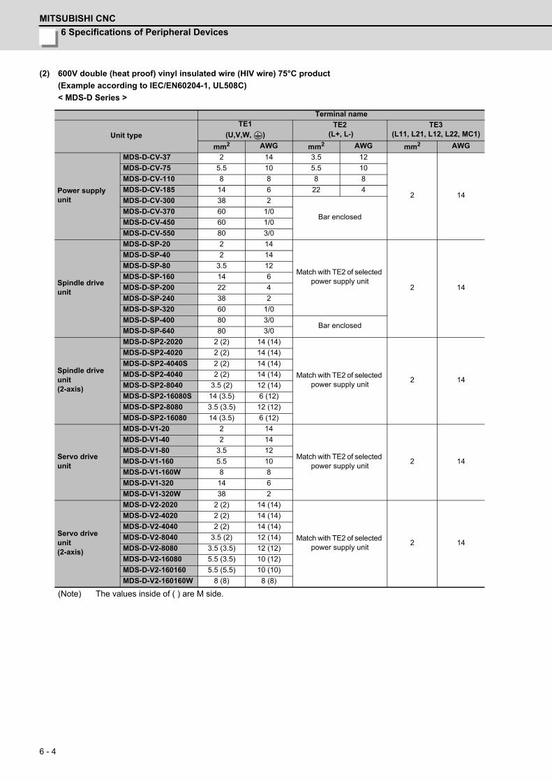
6 Specifications of Peripheral Devices
MITSUBISHI CNC
6 - 4
(2) 600V double (heat proof) vinyl insulated wire (HIV wire) 75°C product
(Example according to IEC/EN60204-1, UL508C)
< MDS-D Series >
(Note) The values inside of ( ) are M side.
Terminal name
Unit type
TE1
(U,V,W, )TE2
(L+, L-)TE3
(L11, L21, L12, L22, MC1)
mm2 AWG mm2 AWG mm2 AWG
Power supplyunit
MDS-D-CV-37 2 14 3.5 12
2 14
MDS-D-CV-75 5.5 10 5.5 10
MDS-D-CV-110 8 8 8 8
MDS-D-CV-185 14 6 22 4
MDS-D-CV-300 38 2
Bar enclosedMDS-D-CV-370 60 1/0
MDS-D-CV-450 60 1/0
MDS-D-CV-550 80 3/0
Spindle drive unit
MDS-D-SP-20 2 14
Match with TE2 of selected power supply unit
2 14
MDS-D-SP-40 2 14
MDS-D-SP-80 3.5 12
MDS-D-SP-160 14 6
MDS-D-SP-200 22 4
MDS-D-SP-240 38 2
MDS-D-SP-320 60 1/0
MDS-D-SP-400 80 3/0Bar enclosed
MDS-D-SP-640 80 3/0
Spindle drive unit(2-axis)
MDS-D-SP2-2020 2 (2) 14 (14)
Match with TE2 of selected power supply unit
2 14
MDS-D-SP2-4020 2 (2) 14 (14)
MDS-D-SP2-4040S 2 (2) 14 (14)
MDS-D-SP2-4040 2 (2) 14 (14)
MDS-D-SP2-8040 3.5 (2) 12 (14)
MDS-D-SP2-16080S 14 (3.5) 6 (12)
MDS-D-SP2-8080 3.5 (3.5) 12 (12)
MDS-D-SP2-16080 14 (3.5) 6 (12)
Servo drive unit
MDS-D-V1-20 2 14
Match with TE2 of selected power supply unit
2 14
MDS-D-V1-40 2 14
MDS-D-V1-80 3.5 12
MDS-D-V1-160 5.5 10
MDS-D-V1-160W 8 8
MDS-D-V1-320 14 6
MDS-D-V1-320W 38 2
Servo drive unit(2-axis)
MDS-D-V2-2020 2 (2) 14 (14)
Match with TE2 of selected power supply unit
2 14
MDS-D-V2-4020 2 (2) 14 (14)
MDS-D-V2-4040 2 (2) 14 (14)
MDS-D-V2-8040 3.5 (2) 12 (14)
MDS-D-V2-8080 3.5 (3.5) 12 (12)
MDS-D-V2-16080 5.5 (3.5) 10 (12)
MDS-D-V2-160160 5.5 (5.5) 10 (10)
MDS-D-V2-160160W 8 (8) 8 (8)

MDS-D/DH Series Specifications Manual
6-1 Selection of wire
6 - 5
< MDS-DH Series >
(Note) The values inside of ( ) are M side.
Terminal name
Unit type
TE1
(U,V,W, )TE2
(L+, L-)TE3
(L11, L21, L12, L22, MC1)
mm2 AWG mm2 AWG mm2 AWG
Power supplyunit
MDS-DH-CV-37 2 14 2 14
2 14
MDS-DH-CV-75 2 14 2 14
MDS-DH-CV-110 3.5 12 5.5 10
MDS-DH-CV-185 8 8 8 8
MDS-DH-CV-300 14 6 22 4
MDS-DH-CV-370 22 4 22 4
MDS-DH-CV-450 22 438 or bar enclosed
2 or bar enclosed
MDS-DH-CV-550 38 2Bar enclosed
MDS-DH-CV-750 60 1/0
Spindle drive unit
MDS-DH-SP-20 2 14
Match with TE2 of selected power supply unit
2 14
MDS-DH-SP-40 2 14
MDS-DH-SP-80 3.5 12
MDS-DH-SP-100 5.5 10
MDS-DH-SP-160 14 6
MDS-DH-SP-200 22 4
MDS-DH-SP-320 38 2Bar enclosed
MDS-DH-SP-480 80 3/0
Servo drive unit
MDS-DH-V1-10 2 14
Match with TE2 of selected power supply unit
2 14
MDS-DH-V1-20 2 14
MDS-DH-V1-40 2 14
MDS-DH-V1-80 3.5 12
MDS-DH-V1-80W 5.5 10
MDS-DH-V1-160 8 8
MDS-DH-V1-160W 8 8
MDS-DH-V1-200 22 4
Servo drive unit(2-axis)
MDS-DH-V2-1010 2 (2) 14 (14)
Match with TE2 of selected power supply unit
2 14
MDS-DH-V2-2010 2 (2) 14 (14)
MDS-DH-V2-2020 2 (2) 14 (14)
MDS-DH-V2-4020 2 (2) 14 (14)
MDS-DH-V2-4040 2 (2) 14 (14)
MDS-DH-V2-8040 3.5 (2) 12 (14)
MDS-DH-V2-8080 3.5 (3.5) 12 (12)
MDS-DH-V2-8080W 5.5 (5.5) 10 (10)

6 Specifications of Peripheral Devices
MITSUBISHI CNC
6 - 6
(3) 600V bridge polyethylene insulated wire (IC) 105 °C product
(Example according to JEAC8001)
< MDS-D Series >
(Note) The values inside of ( ) are M side.
Terminal name
Unit type
TE1
(U,V,W, )TE2
(L+, L-)TE3
(L11, L21, L12, L22, MC1)
mm2 AWG mm2 AWG mm2 AWG
Power supply unit
MDS-D-CV-37 2 14 2 14
1.25 to 2 16 to 14
MDS-D-CV-75 3.5 12 3.5 12
MDS-D-CV-110 5.5 10 14 6
MDS-D-CV-185 14 6 22 4
MDS-D-CV-300 38 2 50 1
MDS-D-CV-370 38 2 60 1/0
MDS-D-CV-450 60 1/0 60 1/0
MDS-D-CV-550 60 1/0 Bar enclosed
Spindle driveunit
MDS-D-SP-20 2 14
Match with TE2 of selected power supply unit
1.25 to 2 16 to 14
MDS-D-SP-40 2 14
MDS-D-SP-80 3.5 12
MDS-D-SP-160 8 8
MDS-D-SP-200 22 4
MDS-D-SP-240 22 4
MDS-D-SP-320 38 2
MDS-D-SP-400 60 1/0Bar enclosed
MDS-D-SP-640 80 3/0
Spindle driveunit(2-axis)
MDS-D-SP2-2020 2 (2) 14 (14)
Match with TE2 of selected power supply unit
1.25 to 2 16 to 14
MDS-D-SP2-4020 2 (2) 14 (14)
MDS-D-SP2-4040S 2 (2) 14 (14)
MDS-D-SP2-4040 2 (2) 14 (14)
MDS-D-SP2-8040 3.5 (2) 12 (14)
MDS-D-SP2-16080S 8 (3.5) 8 (12)
MDS-D-SP2-8080 3.5 (3.5) 12(12)
MDS-D-SP2-16080 8 (3.5) 8(12)
Servo driveunit
MDS-D-V1-20 2 14
Match with TE2 of selected power supply unit
1.25 to 2 16 to 14
MDS-D-V1-40 2 14
MDS-D-V1-80 2 14
MDS-D-V1-160 3.5 12
MDS-D-V1-160W 5.5 10
MDS-D-V1-320 14 6
MDS-D-V1-320W 22 4
Servo driveunit(2-axis)
MDS-D-V2-2020 2 (2) 14 (14)
Match with TE2 of selected power supply unit
1.25 to 2 16 to 14
MDS-D-V2-4020 2 (2) 14 (14)
MDS-D-V2-4040 2 (2) 14 (14)
MDS-D-V2-8040 2 (2) 14 (14)
MDS-D-V2-8080 2 (2) 14 (14)
MDS-D-V2-16080 3.5 (2) 12 (14)
MDS-D-V2-160160 3.5 (3.5) 12 (12)
MDS-D-V2-160160W 5.5 (5.5) 10 (10)
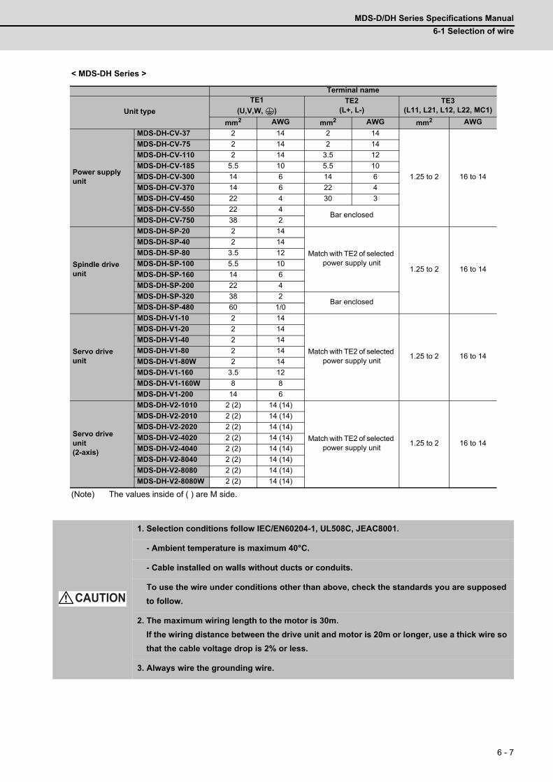
MDS-D/DH Series Specifications Manual
6-1 Selection of wire
6 - 7
< MDS-DH Series >
(Note) The values inside of ( ) are M side.
Terminal name
Unit type
TE1
(U,V,W, )TE2
(L+, L-)TE3
(L11, L21, L12, L22, MC1)
mm2 AWG mm2 AWG mm2 AWG
Power supply unit
MDS-DH-CV-37 2 14 2 14
1.25 to 2 16 to 14
MDS-DH-CV-75 2 14 2 14
MDS-DH-CV-110 2 14 3.5 12
MDS-DH-CV-185 5.5 10 5.5 10
MDS-DH-CV-300 14 6 14 6
MDS-DH-CV-370 14 6 22 4
MDS-DH-CV-450 22 4 30 3
MDS-DH-CV-550 22 4Bar enclosed
MDS-DH-CV-750 38 2
Spindle driveunit
MDS-DH-SP-20 2 14
Match with TE2 of selected power supply unit
1.25 to 2 16 to 14
MDS-DH-SP-40 2 14
MDS-DH-SP-80 3.5 12
MDS-DH-SP-100 5.5 10
MDS-DH-SP-160 14 6
MDS-DH-SP-200 22 4
MDS-DH-SP-320 38 2Bar enclosed
MDS-DH-SP-480 60 1/0
Servo driveunit
MDS-DH-V1-10 2 14
Match with TE2 of selected power supply unit
1.25 to 2 16 to 14
MDS-DH-V1-20 2 14
MDS-DH-V1-40 2 14
MDS-DH-V1-80 2 14
MDS-DH-V1-80W 2 14
MDS-DH-V1-160 3.5 12
MDS-DH-V1-160W 8 8
MDS-DH-V1-200 14 6
Servo driveunit(2-axis)
MDS-DH-V2-1010 2 (2) 14 (14)
Match with TE2 of selected power supply unit
1.25 to 2 16 to 14
MDS-DH-V2-2010 2 (2) 14 (14)
MDS-DH-V2-2020 2 (2) 14 (14)
MDS-DH-V2-4020 2 (2) 14 (14)
MDS-DH-V2-4040 2 (2) 14 (14)
MDS-DH-V2-8040 2 (2) 14 (14)
MDS-DH-V2-8080 2 (2) 14 (14)
MDS-DH-V2-8080W 2 (2) 14 (14)
1. Selection conditions follow IEC/EN60204-1, UL508C, JEAC8001.
- Ambient temperature is maximum 40°C.
- Cable installed on walls without ducts or conduits.
To use the wire under conditions other than above, check the standards you are supposed
to follow.
2. The maximum wiring length to the motor is 30m.
If the wiring distance between the drive unit and motor is 20m or longer, use a thick wire so
that the cable voltage drop is 2% or less.
3. Always wire the grounding wire.
CAUTION
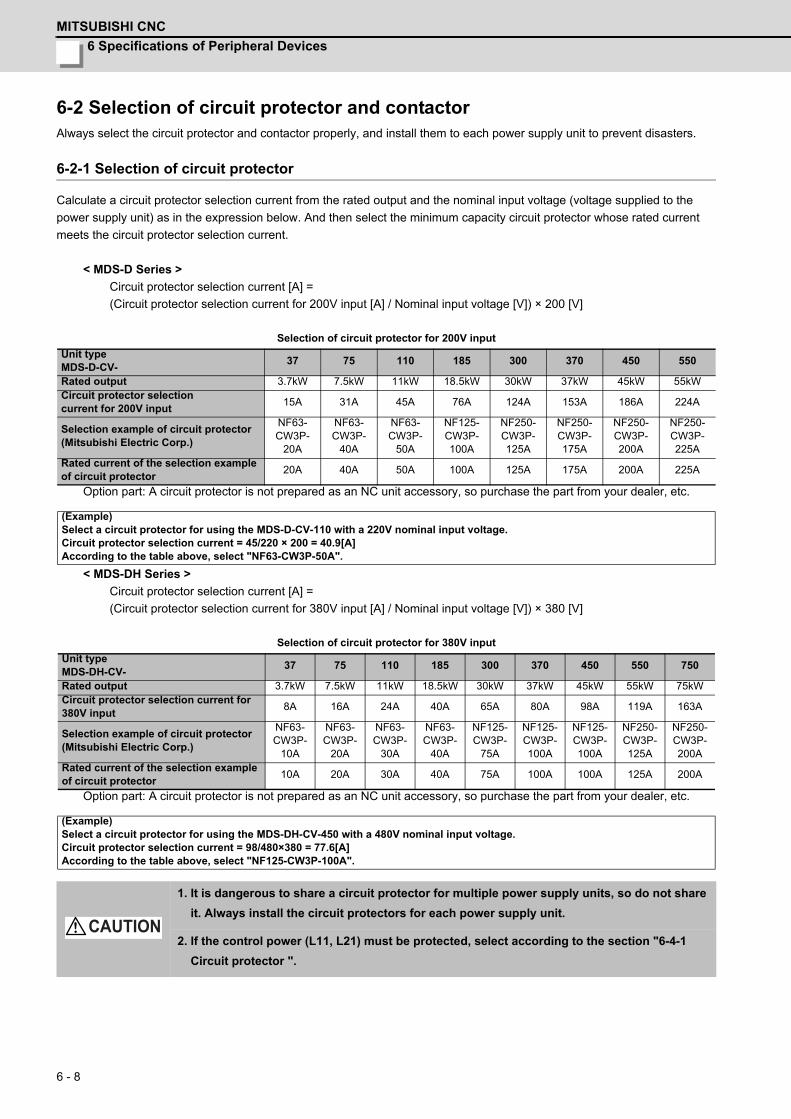
6 Specifications of Peripheral Devices
MITSUBISHI CNC
6 - 8
6-2 Selection of circuit protector and contactorAlways select the circuit protector and contactor properly, and install them to each power supply unit to prevent disasters.
6-2-1 Selection of circuit protector
Calculate a circuit protector selection current from the rated output and the nominal input voltage (voltage supplied to the
power supply unit) as in the expression below. And then select the minimum capacity circuit protector whose rated current
meets the circuit protector selection current.
< MDS-D Series >
Circuit protector selection current [A] =
(Circuit protector selection current for 200V input [A] / Nominal input voltage [V]) × 200 [V]
Selection of circuit protector for 200V input
Option part: A circuit protector is not prepared as an NC unit accessory, so purchase the part from your dealer, etc.
< MDS-DH Series >
Circuit protector selection current [A] =
(Circuit protector selection current for 380V input [A] / Nominal input voltage [V]) × 380 [V]
Selection of circuit protector for 380V input
Option part: A circuit protector is not prepared as an NC unit accessory, so purchase the part from your dealer, etc.
Unit typeMDS-D-CV-
37 75 110 185 300 370 450 550
Rated output 3.7kW 7.5kW 11kW 18.5kW 30kW 37kW 45kW 55kWCircuit protector selection current for 200V input
15A 31A 45A 76A 124A 153A 186A 224A
Selection example of circuit protector(Mitsubishi Electric Corp.)
NF63-CW3P-
20A
NF63-CW3P-
40A
NF63-CW3P-
50A
NF125-CW3P-100A
NF250-CW3P-125A
NF250-CW3P-175A
NF250-CW3P-200A
NF250-CW3P-225A
Rated current of the selection exampleof circuit protector
20A 40A 50A 100A 125A 175A 200A 225A
(Example)Select a circuit protector for using the MDS-D-CV-110 with a 220V nominal input voltage.Circuit protector selection current = 45/220 × 200 = 40.9[A]According to the table above, select "NF63-CW3P-50A".
Unit typeMDS-DH-CV-
37 75 110 185 300 370 450 550 750
Rated output 3.7kW 7.5kW 11kW 18.5kW 30kW 37kW 45kW 55kW 75kWCircuit protector selection current for 380V input
8A 16A 24A 40A 65A 80A 98A 119A 163A
Selection example of circuit protector(Mitsubishi Electric Corp.)
NF63-CW3P-
10A
NF63-CW3P-
20A
NF63-CW3P-
30A
NF63-CW3P-
40A
NF125-CW3P-
75A
NF125-CW3P-100A
NF125-CW3P-100A
NF250-CW3P-125A
NF250-CW3P-200A
Rated current of the selection exampleof circuit protector
10A 20A 30A 40A 75A 100A 100A 125A 200A
(Example)Select a circuit protector for using the MDS-DH-CV-450 with a 480V nominal input voltage.Circuit protector selection current = 98/480×380 = 77.6[A]According to the table above, select "NF125-CW3P-100A".
1. It is dangerous to share a circuit protector for multiple power supply units, so do not share
it. Always install the circuit protectors for each power supply unit.
2. If the control power (L11, L21) must be protected, select according to the section "6-4-1
Circuit protector ".
CAUTION
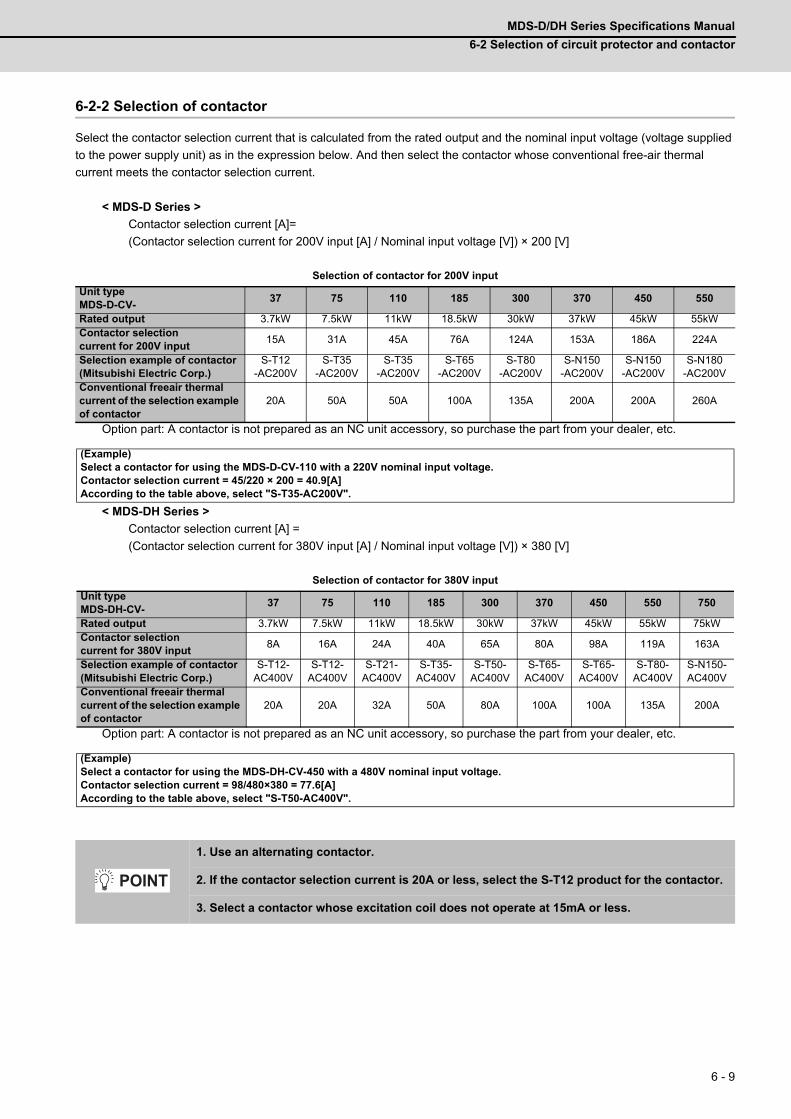
MDS-D/DH Series Specifications Manual
6-2 Selection of circuit protector and contactor
6 - 9
6-2-2 Selection of contactor
Select the contactor selection current that is calculated from the rated output and the nominal input voltage (voltage supplied
to the power supply unit) as in the expression below. And then select the contactor whose conventional free-air thermal
current meets the contactor selection current.
< MDS-D Series >
Contactor selection current [A]=
(Contactor selection current for 200V input [A] / Nominal input voltage [V]) × 200 [V]
Selection of contactor for 200V input
Option part: A contactor is not prepared as an NC unit accessory, so purchase the part from your dealer, etc.
< MDS-DH Series >
Contactor selection current [A] =
(Contactor selection current for 380V input [A] / Nominal input voltage [V]) × 380 [V]
Selection of contactor for 380V input
Option part: A contactor is not prepared as an NC unit accessory, so purchase the part from your dealer, etc.
Unit typeMDS-D-CV-
37 75 110 185 300 370 450 550
Rated output 3.7kW 7.5kW 11kW 18.5kW 30kW 37kW 45kW 55kWContactor selection current for 200V input
15A 31A 45A 76A 124A 153A 186A 224A
Selection example of contactor(Mitsubishi Electric Corp.)
S-T12-AC200V
S-T35-AC200V
S-T35-AC200V
S-T65-AC200V
S-T80-AC200V
S-N150-AC200V
S-N150-AC200V
S-N180-AC200V
Conventional freeair thermal current of the selection example of contactor
20A 50A 50A 100A 135A 200A 200A 260A
(Example)Select a contactor for using the MDS-D-CV-110 with a 220V nominal input voltage.Contactor selection current = 45/220 × 200 = 40.9[A]According to the table above, select "S-T35-AC200V".
Unit typeMDS-DH-CV-
37 75 110 185 300 370 450 550 750
Rated output 3.7kW 7.5kW 11kW 18.5kW 30kW 37kW 45kW 55kW 75kWContactor selectioncurrent for 380V input
8A 16A 24A 40A 65A 80A 98A 119A 163A
Selection example of contactor(Mitsubishi Electric Corp.)
S-T12-AC400V
S-T12-AC400V
S-T21-AC400V
S-T35-AC400V
S-T50-AC400V
S-T65-AC400V
S-T65-AC400V
S-T80-AC400V
S-N150-AC400V
Conventional freeair thermal current of the selection example of contactor
20A 20A 32A 50A 80A 100A 100A 135A 200A
(Example)Select a contactor for using the MDS-DH-CV-450 with a 480V nominal input voltage.Contactor selection current = 98/480×380 = 77.6[A]According to the table above, select "S-T50-AC400V".
1. Use an alternating contactor.
2. If the contactor selection current is 20A or less, select the S-T12 product for the contactor.
3. Select a contactor whose excitation coil does not operate at 15mA or less.
POINT
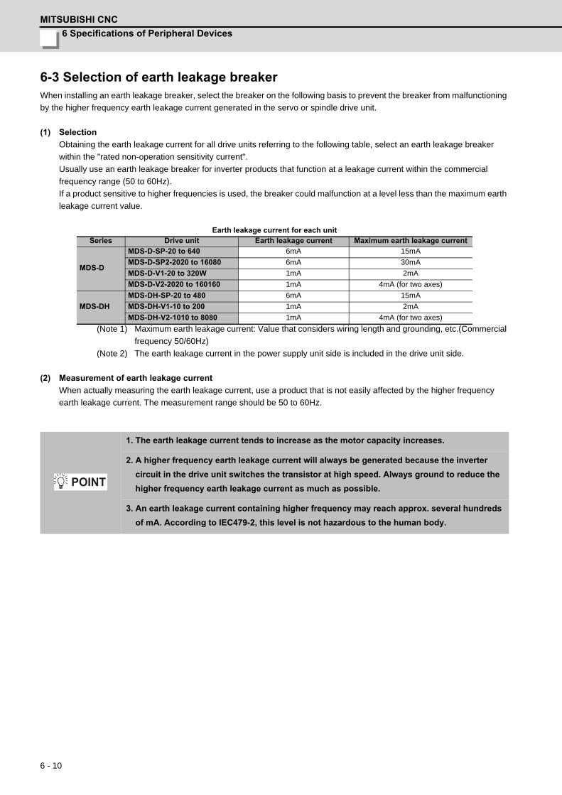
6 Specifications of Peripheral Devices
MITSUBISHI CNC
6 - 10
6-3 Selection of earth leakage breakerWhen installing an earth leakage breaker, select the breaker on the following basis to prevent the breaker from malfunctioning
by the higher frequency earth leakage current generated in the servo or spindle drive unit.
(1) Selection
Obtaining the earth leakage current for all drive units referring to the following table, select an earth leakage breaker
within the "rated non-operation sensitivity current".
Usually use an earth leakage breaker for inverter products that function at a leakage current within the commercial
frequency range (50 to 60Hz).
If a product sensitive to higher frequencies is used, the breaker could malfunction at a level less than the maximum earth
leakage current value.
Earth leakage current for each unit
(Note 1) Maximum earth leakage current: Value that considers wiring length and grounding, etc.(Commercial
frequency 50/60Hz)
(Note 2) The earth leakage current in the power supply unit side is included in the drive unit side.
(2) Measurement of earth leakage current
When actually measuring the earth leakage current, use a product that is not easily affected by the higher frequency
earth leakage current. The measurement range should be 50 to 60Hz.
Series Drive unit Earth leakage current Maximum earth leakage current
MDS-D
MDS-D-SP-20 to 640 6mA 15mA
MDS-D-SP2-2020 to 16080 6mA 30mA
MDS-D-V1-20 to 320W 1mA 2mA
MDS-D-V2-2020 to 160160 1mA 4mA (for two axes)
MDS-DH
MDS-DH-SP-20 to 480 6mA 15mA
MDS-DH-V1-10 to 200 1mA 2mA
MDS-DH-V2-1010 to 8080 1mA 4mA (for two axes)
1. The earth leakage current tends to increase as the motor capacity increases.
2. A higher frequency earth leakage current will always be generated because the inverter
circuit in the drive unit switches the transistor at high speed. Always ground to reduce the
higher frequency earth leakage current as much as possible.
3. An earth leakage current containing higher frequency may reach approx. several hundreds
of mA. According to IEC479-2, this level is not hazardous to the human body.
POINT
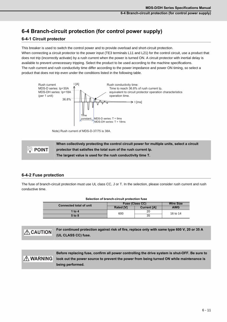
MDS-D/DH Series Specifications Manual
6-4 Branch-circuit protection (for control power supply)
6 - 11
6-4 Branch-circuit protection (for control power supply)6-4-1 Circuit protector
This breaker is used to switch the control power and to provide overload and short-circuit protection.
When connecting a circuit protector to the power input (TE3 terminals L11 and L21) for the control circuit, use a product that
does not trip (incorrectly activate) by a rush current when the power is turned ON. A circuit protector with inertial delay is
available to prevent unnecessary tripping. Select the product to be used according to the machine specifications.
The rush current and rush conductivity time differ according to the power impedance and power ON timing, so select a
product that does not trip even under the conditions listed in the following table.
6-4-2 Fuse protection
The fuse of branch-circuit protection must use UL class CC, J or T. In the selection, please consider rush current and rush
conductive time.
Selection of branch-circuit protection fuse
When collectively protecting the control circuit power for multiple units, select a circuit
protector that satisfies the total sum of the rush current Ip.
The largest value is used for the rush conductivity time T.
Connected total of unitFuse (Class CC) Wire Size
Rated [V] Current [A] AWG1 to 4
60020
16 to 145 to 8 35
For continued protection against risk of fire, replace only with same type 600 V, 20 or 35 A
(UL CLASS CC) fuse.
Before replacing fuse, confirm all power controlling the drive system is shut-OFF. Be sure to
look out the power source to prevent the power from being turned ON while maintenance is
being performed.
t [ms]
Time constant: MDS-D series: T = 9ms MDS-DH series: T = 18ms
Note) Rush current of MDS-D-37/75 is 38A.
I [A] Rush conductivity time: Time to reach 36.8% of rush current Ip, equivalent to circuit protector operation characteristics operation time.
Rush currentMDS-D series: Ip=30AMDS-DH series: Ip=18A(per 1 unit)
36.8%
POINT
CAUTION
WARNING

6 Specifications of Peripheral Devices
MITSUBISHI CNC
6 - 12
6-5 Noise filter(1) Selection
Use an EMC noise filter if the noise conducted to the power line must be reduced. Select an EMC noise filter taking the
power supply unit's input rated voltage and input rated current into consideration.
(2) Noise filter mounting position
Install the noise filter to the power supply unit's power input as the diagram below indicates.
(Note) The noise filter must be prepared by the user.
Recommended devices:
MDS-D Series
Densei-lambda MX13 Series
Soshin Electric HF3000C-TM Series
MDS-DH Series
Okaya Electric Industries 3SUP-HL-ER-6B Series
Soshin Electric HF3000C-TMA Series
Contact:
Densei-lambda Co., Ltd. Telephone: 0120-507039 http://www.densei-lambda.com
Soshin Electric Co., Ltd. Telephone: 03-3775-9112 (+81-3-3775-9112) http://www.soshin.co.jp
(Note) The above devices may be changed at the manufacturer's discretion.
Contact each manufacturer for more information.
MDS-D/DH-CV
RST
Power distribution panel
Breaker
Power supply
Noise filter
AC reactor Contactor Power supply unit
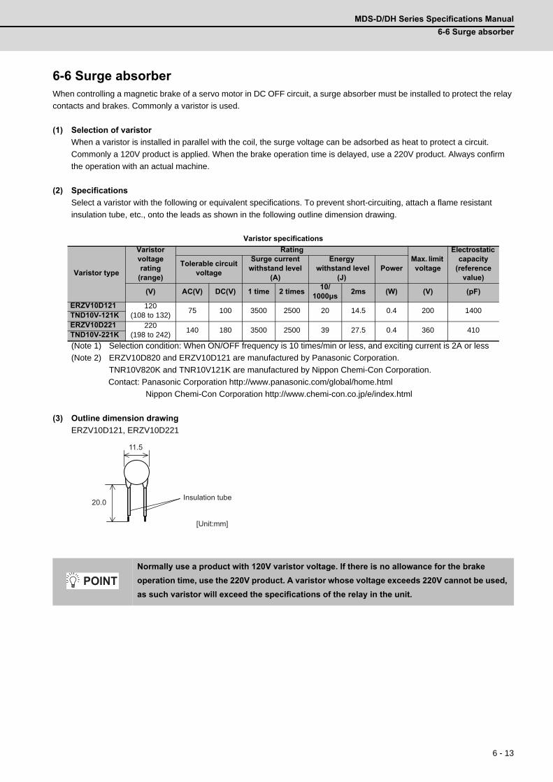
MDS-D/DH Series Specifications Manual
6-6 Surge absorber
6 - 13
6-6 Surge absorberWhen controlling a magnetic brake of a servo motor in DC OFF circuit, a surge absorber must be installed to protect the relay
contacts and brakes. Commonly a varistor is used.
(1) Selection of varistor
When a varistor is installed in parallel with the coil, the surge voltage can be adsorbed as heat to protect a circuit.
Commonly a 120V product is applied. When the brake operation time is delayed, use a 220V product. Always confirm
the operation with an actual machine.
(2) Specifications
Select a varistor with the following or equivalent specifications. To prevent short-circuiting, attach a flame resistant
insulation tube, etc., onto the leads as shown in the following outline dimension drawing.
Varistor specifications
(Note 1) Selection condition: When ON/OFF frequency is 10 times/min or less, and exciting current is 2A or less
(Note 2) ERZV10D820 and ERZV10D121 are manufactured by Panasonic Corporation.
TNR10V820K and TNR10V121K are manufactured by Nippon Chemi-Con Corporation.
Contact: Panasonic Corporation http://www.panasonic.com/global/home.html
Nippon Chemi-Con Corporation http://www.chemi-con.co.jp/e/index.html
(3) Outline dimension drawing
ERZV10D121, ERZV10D221
Varistor type
Varistor voltage rating
(range)
RatingMax. limit voltage
Electrostatic capacity
(reference value)
Tolerable circuit voltage
Surge current withstand level
(A)
Energy withstand level
(J)Power
(V) AC(V) DC(V) 1 time 2 times10/
1000μs2ms (W) (V) (pF)
ERZV10D121 120(108 to 132)
75 100 3500 2500 20 14.5 0.4 200 1400TND10V-121KERZV10D221 220
(198 to 242)140 180 3500 2500 39 27.5 0.4 360 410
TND10V-221K
Normally use a product with 120V varistor voltage. If there is no allowance for the brake
operation time, use the 220V product. A varistor whose voltage exceeds 220V cannot be used,
as such varistor will exceed the specifications of the relay in the unit.
[Unit:mm]
Insulation tube
11.5
20.0
POINT
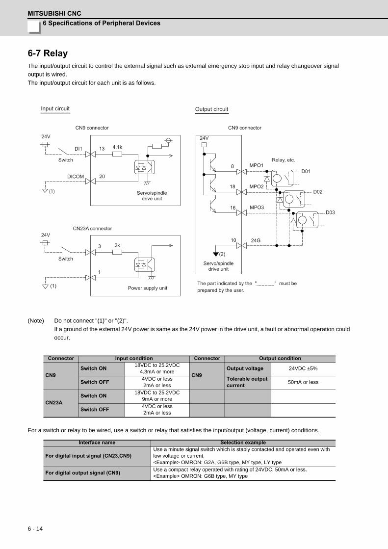
6 Specifications of Peripheral Devices
MITSUBISHI CNC
6 - 14
6-7 RelayThe input/output circuit to control the external signal such as external emergency stop input and relay changeover signal
output is wired.
The input/output circuit for each unit is as follows.
(Note) Do not connect "(1)" or "(2)".
If a ground of the external 24V power is same as the 24V power in the drive unit, a fault or abnormal operation could
occur.
For a switch or relay to be wired, use a switch or relay that satisfies the input/output (voltage, current) conditions.
Connector Input condition Connector Output condition
CN9Switch ON
18VDC to 25.2VDC4.3mA or more
CN9Output voltage 24VDC ±5%
Switch OFF4VDC or less2mA or less
Tolerable output current
50mA or less
CN23ASwitch ON
18VDC to 25.2VDC9mA or more
Switch OFF4VDC or less2mA or less
Interface name Selection example
For digital input signal (CN23,CN9)Use a minute signal switch which is stably contacted and operated even with low voltage or current.<Example> OMRON: G2A, G6B type, MY type, LY type
For digital output signal (CN9)Use a compact relay operated with rating of 24VDC, 50mA or less.<Example> OMRON: G6B type, MY type
DICOM
DI1 13
20
3
1
2k
24V 24V
24V
(1)
(1)
8
18
16
10
MPO1
MPO2
MPO3
24G
D01
D02
D03
4.1k
(2)
CN9 connector CN9 connector
Servo/spindledrive unit
CN23A connector
Switch
Power supply unit
Input circuit Output circuit
Servo/spindledrive unit
Relay, etc.
The part indicated by the " " must be prepared by the user.
Switch

7 - 1
7
Selection
7 Selection
MITSUBISHI CNC
7 - 2
7-1 Selection of the servo motor7-1-1 Outline
It is important to select a servo motor matched to the purpose of the machine that will be installed. If the servo motor and
machine to be installed do not match, the motor performance cannot be fully realized, and it will also be difficult to adjust the
parameters. Be sure to understand the servo motor characteristics in this chapter to select the correct motor.
(1) Motor inertia
The servo motor has an optimum load inertia scale. If the load inertia exceeds the optimum range, the control becomes
unstable and the servo parameters become difficult to adjust. When the load inertia is too large, decelerate with the
gears (The motor axis conversion load inertia is proportional to the square of the deceleration ratio.), or change to a
motor with a large inertia.
(2) Rated speed
Even with motors having the same capacity, the rated speed will differ according to the motor.
The motor's rated output is designed to be generated at the rated speed, and the output P (W) is expressed with
expression (7-1). Thus, even when the motors have the same capacity, the rated torque will differ according to the rated
speed.
P = 2πNT (W) ---(7-1)
N: Motor speed (1/sec)
T: Output torque (N.m)
In other words, even with motors having the same capacities, the one with the lower rated speed will generate a larger
torque. If generated torque is the same, the drive unit capacity can be downsized. When actually mounted on the
machine, if the positioning distance is short and the motor cannot reach the maximum speed, the motor with the lower
rated speed will have a shorter positioning time. When selecting the motor, consider the axis stroke and usage methods,
and select the motor with the optimum rated speed.
MDS-D/DH Series Specifications Manual
7-1 Selection of the servo motor
7 - 3
7-1-2 Selection of servo motor capacity
The following three elements are used to determine the servo motor capacity.
1. Load inertia ratio
2. Short time characteristics (acceleration/deceleration torque)
3. Continuous characteristics (continuous effective load torque)
Carry out appropriate measures, such as increasing the motor capacity, if any of the above conditions is not fulfilled.
(1) Load inertia ratio
Each servo motor has an appropriate load inertia ratio (load inertia/motor inertia). The control becomes unstable when
the load inertia ratio is too large, and the servo parameter adjustment becomes difficult. It becomes difficult to improve
the surface precision in the feed axis, and the positioning time cannot be shortened in the positioning axis because the
settling time is longer.
If the load inertia ratio exceeds the recommended value in the servo specifications list, increase the motor capacity, and
select so that the load inertia ratio is within the recommended range.
Note that the recommended value for the load inertia ratio is strictly one guideline. This does not mean that controlling of
the load with inertia exceeding the recommended value is impossible.
1. When selecting feed axis servo motors for NC unit machine tools, place importance on the
surface precision during machining. To do this, always select a servo motor with a load
inertia ratio within the recommended value. Select the lowest value possible within that
range.
2. The load inertia ratio for the motor with brakes must be judged based on the motor inertia
for the motor without brakes.
POINT
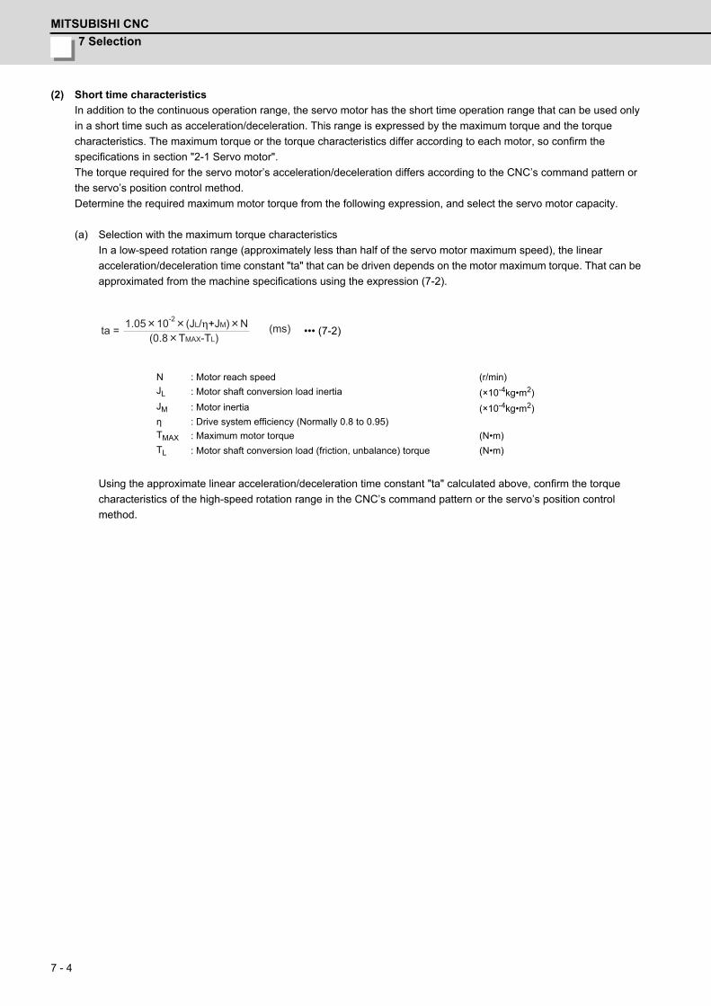
7 Selection
MITSUBISHI CNC
7 - 4
(2) Short time characteristics
In addition to the continuous operation range, the servo motor has the short time operation range that can be used only
in a short time such as acceleration/deceleration. This range is expressed by the maximum torque and the torque
characteristics. The maximum torque or the torque characteristics differ according to each motor, so confirm the
specifications in section "2-1 Servo motor".
The torque required for the servo motor’s acceleration/deceleration differs according to the CNC’s command pattern or
the servo’s position control method.
Determine the required maximum motor torque from the following expression, and select the servo motor capacity.
(a) Selection with the maximum torque characteristics
In a low-speed rotation range (approximately less than half of the servo motor maximum speed), the linear
acceleration/deceleration time constant "ta" that can be driven depends on the motor maximum torque. That can be
approximated from the machine specifications using the expression (7-2).
••• (7-2)
Using the approximate linear acceleration/deceleration time constant "ta" calculated above, confirm the torque
characteristics of the high-speed rotation range in the CNC’s command pattern or the servo’s position control
method.
N : Motor reach speed (r/min)
JL : Motor shaft conversion load inertia (×10-4kg•m2)
JM : Motor inertia (×10-4kg•m2)η : Drive system efficiency (Normally 0.8 to 0.95)TMAX : Maximum motor torque (N•m)
TL : Motor shaft conversion load (friction, unbalance) torque (N•m)
ta =(0.8 TMAX-TL)
1.05 10-2 (JL/η+JM) N (ms)
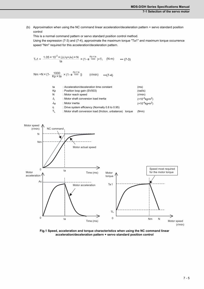
MDS-D/DH Series Specifications Manual
7-1 Selection of the servo motor
7 - 5
(b) Approximation when using the NC command linear acceleration/deceleration pattern + servo standard position
control
This is a normal command pattern or servo standard position control method.
Using the expression (7-3) and (7-4), approximate the maximum torque "Ta1" and maximum torque occurrence
speed "Nm" required for this acceleration/deceleration pattern.
••• (7-3)
•••(7-4)
Fig.1 Speed, acceleration and torque characteristics when using the NC command linear acceleration/deceleration pattern + servo standard position control
ta : Acceleration/deceleration time constant (ms)Kp : Position loop gain (SV003) (rad/s)N : Motor reach speed (r/min)
JL : Motor shaft conversion load inertia (×10-4kg•m2)
JM : Motor inertia (×10-4kg•m2)η : Drive system efficiency (Normally 0.8 to 0.95)TL : Motor shaft conversion load (friction, unbalance) torque (N•m)
Ta1 =ta
(N.m)(1- e )+TL-Kp ta
1000
Nm =N 1- Kp ta1000 (r/min)(1- e )
-Kp ta1000
(ms)
(r/min)
0 ta
N
(ms) 0 ta
Ac
Nm
(r/min)
0 Nm
Ta1
TL
N Time Motor speed
Motor speedNC command
Motor actual speed
Motor acceleration
TimeMotoracceleration
Motortorque
Speed most required for the motor torque
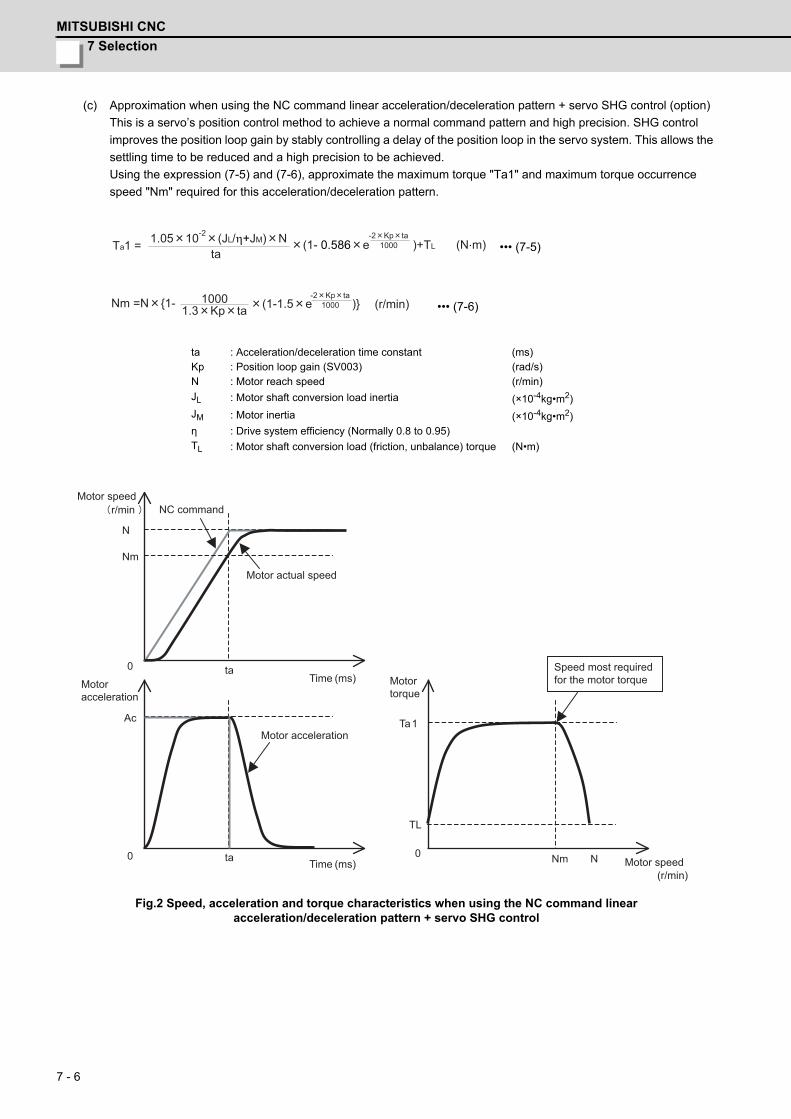
7 Selection
MITSUBISHI CNC
7 - 6
(c) Approximation when using the NC command linear acceleration/deceleration pattern + servo SHG control (option)
This is a servo’s position control method to achieve a normal command pattern and high precision. SHG control
improves the position loop gain by stably controlling a delay of the position loop in the servo system. This allows the
settling time to be reduced and a high precision to be achieved.
Using the expression (7-5) and (7-6), approximate the maximum torque "Ta1" and maximum torque occurrence
speed "Nm" required for this acceleration/deceleration pattern.
••• (7-5)
••• (7-6)
Fig.2 Speed, acceleration and torque characteristics when using the NC command linear acceleration/deceleration pattern + servo SHG control
ta : Acceleration/deceleration time constant (ms)Kp : Position loop gain (SV003) (rad/s)N : Motor reach speed (r/min)
JL : Motor shaft conversion load inertia (×10-4kg•m2)
JM : Motor inertia (×10-4kg•m2)η : Drive system efficiency (Normally 0.8 to 0.95)TL : Motor shaft conversion load (friction, unbalance) torque (N•m)
Ta1 =ta
(N.m)(1- 0.586 e )+TL-2 Kp ta
1000
Nm =N 1- 1.3 Kp ta1000 (1-1.5 e )
-2 Kp ta1000 (r/min)
(ms)
r/min
0 ta
N
(ms) 0 ta
Ac
Nm
(r/min)
0 Nm
Ta1
TL
N
Time
Time
Motor acceleration
NC commandMotor speed
Motoracceleration
Motortorque
Motor actual speed
Motor speed
Speed most required for the motor torque

MDS-D/DH Series Specifications Manual
7-1 Selection of the servo motor
7 - 7
(d) Approximation when using the NC command soft acceleration/deceleration pattern + feed forward (high-
speed accuracy) control
If the feedforward amount is set properly, the delay of the servo position loop is guaranteed. Therefore, this
command acceleration pattern can be approximated to the NC command and does not depend on the servo
position control method.
Using the expression (7-7) and (7-8), approximate the maximum torque "Ta1" and maximum torque occurrence
speed "Nm" required for this acceleration/deceleration pattern.
••• (7-7)
••• (7-8)
Fig 3. Speed, acceleration and torque characteristic when using the NC command soft acceleration/deceleration pattern + feedforward (high-speed accuracy) control
ta : Acceleration/deceleration time constant (ms)tb : Acceleration/deceleration time constant (ms)N : Motor reach speed (r/min)
JL : Motor shaft conversion load inertia (×10-4kg•m2)
JM : Motor inertia (×10-4kg•m2)η : Drive system efficiency (Normally 0.8 to 0.95)TL : Motor shaft conversion load (friction, unbalance) torque (N•m)
Ta1 =ta
1.05 10-2 (JL/η+JM) N (N.m)+TL
Nm =N (1- ta
1 (r/min)2
tb
(ms)
r/min
0 ta
N
(ms) 0 tb ta ta+ tb
Ac
Nm
0 Nm
Ta1
TL
N
ta+tb Time
Time
Motor speed
(r/min)
NC command Motor actual speed
Motoracceleration
Motortorque
Speed most required for the motor torque
Motor speed

7 Selection
MITSUBISHI CNC
7 - 8
(e) Confirmation in the torque characteristics
Confirm whether the maximum torque "Ta1" and maximum torque occurrence speed "Nm" required for this
acceleration/deceleration pattern calculated in the item "(b)" to "(d)" are in the short time operation range of the
torque characteristics.
Motor torque characteristics
If they are not in the short time operation range, return to the item "(b)" to "(d)" and make the linear acceleration/
deceleration time constant "ta" large.
If the acceleration specification cannot be changed (the linear acceleration/deceleration time constant cannot be
increased), reconsider the selection, such as increasing the motor capacity.
1. In selecting the maximum torque "Ta1" required for this acceleration/deceleration pattern,
the measure of it is 80% of the motor maximum torque "TMAX "
2. In high-speed rotation range, confirm that the maximum torque "Ta1" and maximum torque
occurrence speed "Nm" required for this acceleration/deceleration is in the short time
operation range.
3. The drive system efficiency is normally approx. 0.95 in the ball screw mechanism and
approx. 0.8 in the gear mechanism
4. For the torque characteristics in the motor high-speed rotation range, the AC input voltage
is 200V (200V series) or 380V (400V series). If the input voltage is low or if the power wire
connecting the servo motor and drive unit is long (20m length), the short time operation
range is limited. In this case, an allowance must be provided for the selection of the high-
speed rotation range.
0 2000 4000
0
20
40
100
80
60
Rotation speed [r/min]
Continuous operation range
Short time operation range
Required maximum torque: Ta1 Required maximum torque occurrence speed: Nm
Motor maximum torque
High-speed rotation range torque characteristic
Torq
ue [N
m]
POINT
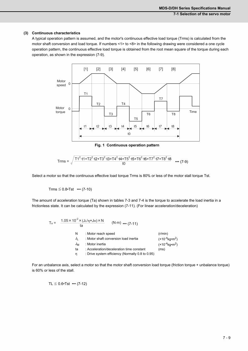
MDS-D/DH Series Specifications Manual
7-1 Selection of the servo motor
7 - 9
(3) Continuous characteristics
A typical operation pattern is assumed, and the motor's continuous effective load torque (Trms) is calculated from the
motor shaft conversion and load torque. If numbers <1> to <8> in the following drawing were considered a one cycle
operation pattern, the continuous effective load torque is obtained from the root mean square of the torque during each
operation, as shown in the expression (7-9).
Fig. 1 Continuous operation pattern
••• (7-9)
Select a motor so that the continuous effective load torque Trms is 80% or less of the motor stall torque Tst.
Trms 0.8•Tst ••• (7-10)
The amount of acceleration torque (Ta) shown in tables 7-3 and 7-4 is the torque to accelerate the load inertia in a
frictionless state. It can be calculated by the expression (7-11). (For linear acceleration/deceleration)
••• (7-11)
For an unbalance axis, select a motor so that the motor shaft conversion load torque (friction torque + unbalance torque)
is 60% or less of the stall.
TL 0.6•Tst ••• (7-12)
N : Motor reach speed (r/min)
JL : Motor shaft conversion load inertia (×10-4kg•m2)
JM : Motor inertia (×10-4kg•m2)ta : Acceleration/deceleration time constant (ms)η : Drive system efficiency (Normally 0.8 to 0.95)
0
0 T3
T2
t1 t2 t3 t4
t0
T1
T4
T5 T6
T7
T8
t5 t6 t7 t8
[1] [2] [3] [4] [5] [6] [7] [8]
Motortorque
Motorspeed
Time
Trms = T12·t1+T22·t2+T32·t3+T42·t4+T52·t5+T62·t6+T72·t7+T82·t8t0
≦
Ta =ta
1.05 10-2 (JL/η+JM) N (N.m)
≦
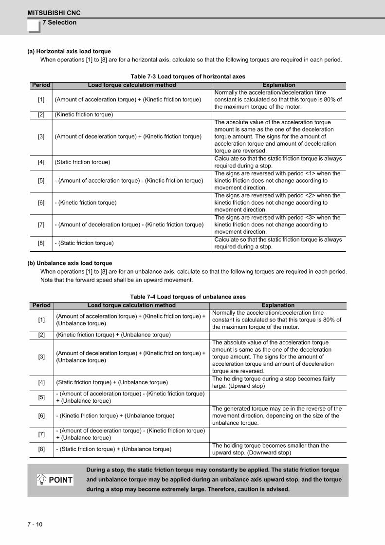
7 Selection
MITSUBISHI CNC
7 - 10
(a) Horizontal axis load torque
When operations [1] to [8] are for a horizontal axis, calculate so that the following torques are required in each period.
Table 7-3 Load torques of horizontal axes
(b) Unbalance axis load torque
When operations [1] to [8] are for an unbalance axis, calculate so that the following torques are required in each period.
Note that the forward speed shall be an upward movement.
Table 7-4 Load torques of unbalance axes
Period Load torque calculation method Explanation
[1] (Amount of acceleration torque) + (Kinetic friction torque)Normally the acceleration/deceleration time constant is calculated so that this torque is 80% of the maximum torque of the motor.
[2] (Kinetic friction torque)
[3] (Amount of deceleration torque) + (Kinetic friction torque)
The absolute value of the acceleration torque amount is same as the one of the deceleration torque amount. The signs for the amount of acceleration torque and amount of deceleration torque are reversed.
[4] (Static friction torque)Calculate so that the static friction torque is always required during a stop.
[5] - (Amount of acceleration torque) - (Kinetic friction torque)The signs are reversed with period <1> when the kinetic friction does not change according to movement direction.
[6] - (Kinetic friction torque)The signs are reversed with period <2> when the kinetic friction does not change according to movement direction.
[7] - (Amount of deceleration torque) - (Kinetic friction torque)The signs are reversed with period <3> when the kinetic friction does not change according to movement direction.
[8] - (Static friction torque)Calculate so that the static friction torque is always required during a stop.
Period Load torque calculation method Explanation
[1](Amount of acceleration torque) + (Kinetic friction torque) + (Unbalance torque)
Normally the acceleration/deceleration time constant is calculated so that this torque is 80% of the maximum torque of the motor.
[2] (Kinetic friction torque) + (Unbalance torque)
[3](Amount of deceleration torque) + (Kinetic friction torque) + (Unbalance torque)
The absolute value of the acceleration torque amount is same as the one of the deceleration torque amount. The signs for the amount of acceleration torque and amount of deceleration torque are reversed.
[4] (Static friction torque) + (Unbalance torque)The holding torque during a stop becomes fairly large. (Upward stop)
[5]- (Amount of acceleration torque) - (Kinetic friction torque) + (Unbalance torque)
[6] - (Kinetic friction torque) + (Unbalance torque)The generated torque may be in the reverse of the movement direction, depending on the size of the unbalance torque.
[7]- (Amount of deceleration torque) - (Kinetic friction torque) + (Unbalance torque)
[8] - (Static friction torque) + (Unbalance torque)The holding torque becomes smaller than the upward stop. (Downward stop)
During a stop, the static friction torque may constantly be applied. The static friction torque
and unbalance torque may be applied during an unbalance axis upward stop, and the torque
during a stop may become extremely large. Therefore, caution is advised.
POINT
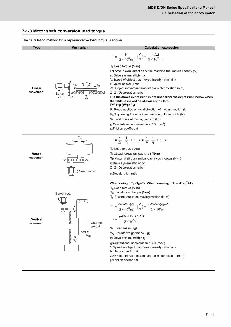
MDS-D/DH Series Specifications Manual
7-1 Selection of the servo motor
7 - 11
7-1-3 Motor shaft conversion load torque
The calculation method for a representative load torque is shown.
Type Mechanism Calculation expression
Linear movement
TL:Load torque (N•m)
F:Force in axial direction of the machine that moves linearly (N)η: Drive system efficiencyV:Speed of object that moves linearly (mm/min)N:Motor speed (r/min)∆S:Object movement amount per motor rotation (mm)Z1,Z2:Deceleration ratio
F in the above expression is obtained from the expression below when the table is moved as shown on the left.F=Fc+μ (W•g+F0)
Fc:Force applied on axial direction of moving section (N)
F0:Tightening force on inner surface of table guide (N)
W:Total mass of moving section (kg)
g:Gravitational acceleration = 9.8 (m/s2)μ:Friction coefficient
Rotary movement
TL:Load torque (N•m)
TL0:Load torque on load shaft (N•m)
TF:Motor shaft conversion load friction torque (N•m)
η:Drive system efficiencyZ1,Z2:Deceleration ratio
n:Deceleration ratio
Vertical movement
When rising TL=TU+TF When lowering TL= -TU•η2+TF
TL:Load torque (N•m)
TU:Unbalanced torque (N•m)
TF:Friction torque on moving section (N•m)
W1:Load mass (kg)
W2:Counterweight mass (kg)
η: Drive system efficiency
g:Gravitational acceleration = 9.8 (m/s2)V:Speed of object that moves linearly (mm/min)N:Motor speed (r/min)∆S:Object movement amount per motor rotation (mm)μ:Friction coefficient
Z2 W
F0FcZ1
Servo motor
TL =F103πη N
.( ) = V
103πηF.ΔS
Z2Z1
TL0
Servo motor
TL = . .TL0+TF = . .TL0+TFη1Z1
n1
η1
Z2
1/n
W1
W2
Servo motor
Counter-weight
Load
TU =(W1-W2).g
103πη N.( ) =
V103πη
(W1-W2).g.ΔS
TF =103πη
μ.(W1+W2).g.ΔS

7 Selection
MITSUBISHI CNC
7 - 12
7-1-4 Expressions for load inertia calculation
The calculation method for a representative load inertia is shown.
Type Mechanism Calculation expression
Cylinder
TL:Load inertia (kg•cm2)
ρ: Density of cylinder material (kg/cm3)L:Length of cylinder (cm)D1:Outer diameter of cylinder (cm)
D2:Inner diameter of cylinder (cm)
W:Mass of cylinder (kg)<Reference data (Material densities)>
Iron:7.80×10⁻³(kg/cm3) Aluminum:2.70×10⁻³(kg/cm3)
Copper:8.96×10⁻³(kg/cm3)
JL:Load inertia (kg•cm2)
W:Mass of cylinder (kg)D:Outer diameter of cylinder (cm)R:Distance between rotary axis and cylinder axis (cm)
ColumnJL: Load inertia (kg•cm2)
W:Mass of cylinder (kg)a,b,R:Left diagram (cm)
Object that moves linearly
JL:Load inertia (kg•cm2)
W:Mass of object that moves linearly (kg)N:Motor speed (r/min)V:Speed of object that moves linearly (mm/min)∆S:Object movement amount per motor rotation (mm)
Suspended object JL:Load inertia (kg•cm2)
W:Object mass (kg)D:Diameter of pulley (cm)
Jp:Inertia of pulley (kg•cm2)
Converted load JL:Load inertia (kg•cm2)
JA,JB:Inertia of load A, B (kg•cm2)
J11 to J31:Inertia (kg•cm2)
N1 to N3:Each shaft’s speed (r/min)
D1.
D2.
Rotary shaft is cylinder center
Rotary shaft
JL = .(D14-D2
4) = .(D1
2+D2
2)
32 8W
R
D
When rotary shaft and cylinder shaft are deviated
Rotary shaft
JL = .(D2+8R
2)
8W
R
aa
bb
Rotary shaft
JL = W( +R2)
3a
2+b
2
W
VN
Servomotor
JL = W( . )2= W( )
2
101 V ΔS
2πN 20π
D
W
JL = W( )2+Jp
D2
N2
JA
JBN3 J31
N1
N1
J11
J22
J21
Load A
Servomotor
Load B JL = J11+(J21+J22+JA).( )2+(J +JB).( )
2
N1
N2
N1
N3

MDS-D/DH Series Specifications Manual
7-2 Selection of the spindle motor
7 - 13
7-2 Selection of the spindle motor(1) Calculation of average output for spindle
In the machine which carries out the spindle’s acceleration/deceleration frequently (example: tapping center), short-time
rating is frequently used, and a rise in temperature become significant on the spindle motor or drive unit. Thus, calculate
the average output (PAV) from one cycle operation pattern and confirm that the calculated value is less than the
continuous rating output of the selected spindle motor.
Continuous operation pattern (example)
P1 to P8 :Outputt1 to t8 :Timet0 :One cycle operation time
1. Calculate acceleration/deceleration time by the accurate load inertia because even if the
rotation speed is the same, acceleration/deceleration time varies with a tool or workpiece
mounted to the spindle.
Refer to the section "Adjusting the acceleration/deceleration operation" (1) in Instruction
Manual.
2. Calculation method of synchronous tapping
The acceleration/deceleration number of times is twice, for forward run and reverse run are
carried out in one machining. The output guideline is 50% of the short-time rating. The time
is tapping time constant.
3. Calculation method of spindle synchronization
The output guideline is 70% of the short-time rating. The time is spindle synchronization
time constant.
0
0
P3
P2
t1 t2 t3 t4
t0
P1
P4
P5 P6
P7
P8
t5 t6 t7 t8
[1] [2] [3] [4] [5] [6] [7] [8]
Motortorque
Motorspeed
TimeOutput during acceleration/deceleration (kW)= Actual acceleration/deceleration output (kW) *
Accelera-tion
Accelera-tion
Decelera-tion
Decelera-tion
Cutting
Cutting
Stop Stop
Actual acceleration/deceleration output (kW) is 1.2-fold of "Standard output (kW) during acceleration/deceleration" or 1.2-fold of "Short time rated output (kW)".
PAV = P12·t1+P22·t2+P32·t3+P42·t4+P52·t5+P62·t6+P72·t7+P82·t8t0
≧Continuous rated output One cycle operation pattern average output (PAV)
POINT
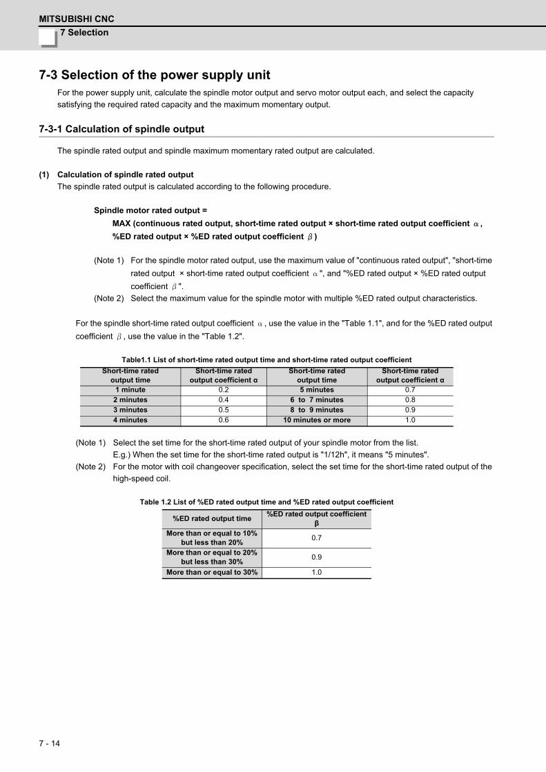
7 Selection
MITSUBISHI CNC
7 - 14
7-3 Selection of the power supply unitFor the power supply unit, calculate the spindle motor output and servo motor output each, and select the capacity
satisfying the required rated capacity and the maximum momentary output.
7-3-1 Calculation of spindle output
The spindle rated output and spindle maximum momentary rated output are calculated.
(1) Calculation of spindle rated output
The spindle rated output is calculated according to the following procedure.
Spindle motor rated output =
MAX (continuous rated output, short-time rated output × short-time rated output coefficient α,
%ED rated output × %ED rated output coefficient β)
(Note 1) For the spindle motor rated output, use the maximum value of "continuous rated output", "short-time
rated output × short-time rated output coefficient α", and "%ED rated output × %ED rated output
coefficient β".
(Note 2) Select the maximum value for the spindle motor with multiple %ED rated output characteristics.
For the spindle short-time rated output coefficient α, use the value in the "Table 1.1", and for the %ED rated output
coefficient β, use the value in the "Table 1.2".
Table1.1 List of short-time rated output time and short-time rated output coefficient
(Note 1) Select the set time for the short-time rated output of your spindle motor from the list.
E.g.) When the set time for the short-time rated output is "1/12h", it means "5 minutes".
(Note 2) For the motor with coil changeover specification, select the set time for the short-time rated output of the
high-speed coil.
Table 1.2 List of %ED rated output time and %ED rated output coefficient
Short-time rated output time
Short-time rated output coefficient α
Short-time rated output time
Short-time rated output coefficient α
1 minute 0.2 5 minutes 0.72 minutes 0.4 6 to 7 minutes 0.83 minutes 0.5 8 to 9 minutes 0.94 minutes 0.6 10 minutes or more 1.0
%ED rated output time%ED rated output coefficient
βMore than or equal to 10%
but less than 20%0.7
More than or equal to 20% but less than 30%
0.9
More than or equal to 30% 1.0
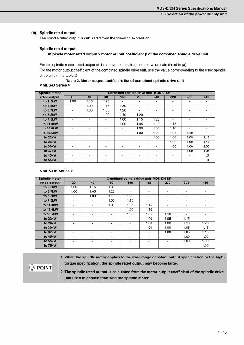
MDS-D/DH Series Specifications Manual
7-3 Selection of the power supply unit
7 - 15
(b) Spindle rated output
The spindle rated output is calculated from the following expression.
Spindle rated output
=Spindle motor rated output x motor output coefficient β of the combined spindle drive unit
For the spindle motor rated output of the above expression, use the value calculated in (a).
For the motor output coefficient of the combined spindle drive unit, use the value corresponding to the used spindle
drive unit in the table 2.
Table 2. Motor output coefficient list of combined spindle drive unit< MDS-D Series >
< MDS-DH Series >
Spindle motorrated output
Combined spindle drive unit MDS-D-SP-20 40 80 160 200 240 320 400 640
to 1.5kW 1.00 1.15 1.25 - - - - - - to 2.2kW - 1.00 1.15 1.30 - - - - - to 3.7kW - 1.00 1.05 1.20 - - - - - to 5.5kW - - 1.00 1.10 1.20 - - - - to 7.5kW - - - 1.00 1.15 1.20 - - -
to 11.0kW - - - 1.00 1.05 1.10 1.15 - - to 15.0kW - - - - 1.00 1.05 1.10 - - to 18.5kW - - - - 1.00 1.00 1.05 1.10 - to 22kW - - - - - 1.00 1.00 1.05 1.15 to 26kW - - - - - - 1.00 1.00 1.10 to 30kW - - - - - - 1.00 1.00 1.05 to 37kW - - - - - - - 1.00 1.05 to 45kW - - - - - - - - 1.0 to 55kW - - - - - - - - 1.0
Spindle motorrated output
Combined spindle drive unit MDS-DH-SP-20 40 80 100 160 200 320 480
to 2.2kW 1.00 1.15 1.30 - - - - - to 3.7kW 1.00 1.05 1.20 - - - - - to 5.5kW - 1.00 1.10 1.20 - - - - to 7.5kW - - 1.00 1.15 - - - -
to 11.0kW - - 1.00 1.05 1.15 - - - to 15.0kW - - - 1.00 1.10 - - - to 18.5kW - - - 1.00 1.05 1.10 - - to 22kW - - - - 1.00 1.05 1.15 - to 26kW - - - - 1.00 1.00 1.10 1.20 to 30kW - - - - 1.00 1.00 1.05 1.15 to 37kW - - - - - 1.00 1.05 1.10 to 45kW - - - - - - 1.00 1.05 to 55kW - - - - - - 1.00 1.00 to 75kW - - - - - - - 1.00
1. When the spindle motor applies to the wide range constant output specification or the high-
torque specification, the spindle rated output may become large.
2. The spindle rated output is calculated from the motor output coefficient of the spindle drive
unit used in combination with the spindle motor.
POINT
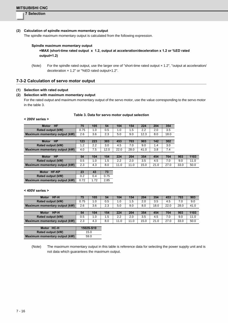
7 Selection
MITSUBISHI CNC
7 - 16
(2) Calculation of spindle maximum momentary output
The spindle maximum momentary output is calculated from the following expression.
Spindle maximum momentary output
=MAX (short-time rated output x 1.2, output at acceleration/deceleration x 1.2 or %ED rated
output×1.2)
(Note) For the spindle rated output, use the larger one of "short-time rated output × 1.2", "output at acceleration/
deceleration × 1.2" or "%ED rated output×1.2".
7-3-2 Calculation of servo motor output
(1) Selection with rated output
(2) Selection with maximum momentary output
For the rated output and maximum momentary output of the servo motor, use the value corresponding to the servo motor
in the table 3.
Table 3. Data for servo motor output selection< 200V series >
< 400V series >
(Note) The maximum momentary output in this table is reference data for selecting the power supply unit and is
not data which guarantees the maximum output.
Motor HF 75 105 54 104 154 224 204 354Rated output (kW) 0.75 1.0 0.5 1.0 1.5 2.2 2.0 3.5
Maximum momentary output (kW) 2.6 3.6 2.3 5.0 9.0 12.3 8.0 18.0
Motor HP 123 223 303 453 703 903 142 302Rated output (kW) 1.2 2.2 3.0 4.5 7.0 9.0 1.4 3.0
Maximum momentary output (kW) 4.0 7.5 12.0 22.0 28.0 41.0 3.8 7.4
Motor HP 54 104 154 224 204 354 454 704 903 1103Rated output (kW) 0.5 1.0 1.5 2.2 2.0 3.5 4.5 7.0 9.0 11.0
Maximum momentary output (kW) 2.3 4.3 8.0 11.0 11.0 15.0 21.0 27.0 33.0 50.0
Motor HF-KP 23 43 73Rated output (kW) 0.2 0.4 0.75
Maximum momentary output (kW) 0.72 1.72 2.85
Motor HF-H 75 105 54 104 154 204 354 453 703 903Rated output (kW) 0.75 1.0 0.5 1.0 1.5 2.0 3.5 4.5 7.0 9.0
Maximum momentary output (kW) 2.6 3.6 2.3 5.0 9.0 8.0 18.0 22.0 28.0 41.0
Motor HP-H 54 104 154 224 204 354 454 704 903 1103Rated output (kW) 0.5 1.0 1.5 2.2 2.0 3.5 4.5 7.0 9.0 11.0
Maximum momentary output (kW) 2.3 4.3 8.0 11.0 11.0 15.0 21.0 27.0 33.0 50.0
Motor HC-H 1502S-S10Rated output (kW) 15.0
Maximum momentary output (kW) 59.0
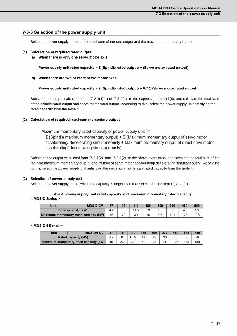
MDS-D/DH Series Specifications Manual
7-3 Selection of the power supply unit
7 - 17
7-3-3 Selection of the power supply unit
Select the power supply unit from the total sum of the rate output and the maximum momentary output.
(1) Calculation of required rated output
(a) When there is only one servo motor axis
Power supply unit rated capacity > Σ (Spindle rated output) + (Servo motor rated output)
(b) When there are two or more servo motor axes
Power supply unit rated capacity > Σ (Spindle rated output) + 0.7 Σ (Servo motor rated output)
Substitute the output calculated from "7-2-1(1)" and "7-2-2(1)" to the expression (a) and (b), and calculate the total sum
of the spindle rated output and servo motor rated output. According to this, select the power supply unit satisfying the
rated capacity from the table 4.
(2) Calculation of required maximum momentary output
Substitute the output calculated from "7-2-1(2)" and "7-2-2(2)" to the above expression, and calculate the total sum of the
"spindle maximum momentary output" and "output of servo motor accelerating/ decelerating simultaneously". According
to this, select the power supply unit satisfying the maximum momentary rated capacity from the table 4.
(3) Selection of power supply unit
Select the power supply unit of which the capacity is larger than that selected in the item (1) and (2).
Table 4. Power supply unit rated capacity and maximum momentary rated capacity< MDS-D Series >
< MDS-DH Series >
Unit MDS-D-CV- 37 75 110 185 300 370 450 550
Rated capacity (kW) 4.2 8 11.5 19 31 38 46 56
Maximum momentary rated capacity (kW) 16 23 39 60 92 101 125 175
Unit MDS-DH-CV- 37 75 110 185 300 370 450 550 750
Rated capacity (kW) 4.2 8 11.5 19 31 38 46 56 76
Maximum momentary rated capacity (kW) 16 23 39 60 92 101 125 175 180
Maximum momentary rated capacity of power supply unit ≧Σ (Spindle maximum momentary output) + Σ (Maximum momentary output of servo motor accelerating/ decelerating simultaneously + Maximum momentary output of direct drive motor accelerating/ decelerating simultaneously)

7 Selection
MITSUBISHI CNC
7 - 18
1. When two or more servo motor axes are connected, do the calculation with the largest rated
capacity of the servo motor if a value obtained by multiplying the total sum of the servo
motor rated output by "0.7" is smaller than the largest rated capacity of the servo motors.
Example: HF Series
(1)For "HF903 (9.0kW) + HF104 (1.0kW)", "0.7 x (9.0 + 1.0) =7.0 < 9.0" is applied.
So, do the calculation with applying "9.0kW" to the total sum of the servo motor's rated
output.
(2)For "HF903 (9.0kW) + HF903 (9.0kW)", "0.7 x (9.0 + 9.0) = 12.6 > 9.0" is applied.
So, do the calculation with applying "12.6kW" to the total sum of the servo motor's rated
output.
Example: HF-H Series
(1)For "HF-H903 (9.0kW) + HF-H104 (1.0kW)", "0.7 x (9.0 + 1.0) =7.0 < 9.0" is applied.
So, do the calculation with applying "9.0kW" to the total sum of the servo motor's rated
output.
(2)For "HF-H903 (9.0kW) + HF-H903 (9.0kW)", "0.7 x (9.0 + 9.0) = 12.6 > 9.0" is applied.
So, do the calculation with applying "12.6kW" to the total sum of the servo motor's rated
output.
2. When reducing the time constant replacing the conventional motor with the HF, HP, HF-KP,
HF-H, HP-H or HC-H Series motor, the power supply capacity may rise because the motor
maximum momentary output increases more than the conventional motor. Therefore, make
sure to check the selection with maximum momentary rated capacity.
3. When the large capacity drive unit (MDS-D-SP-400/640, MDS-DH-SP-200/320/450, MDS-DH-
V1-200) is connected to the power supply unit, always install the drive unit proximally in the
left side of the power supply unit and connect PN terminal with the dedicated DC
connection bar.
4. When using two large capacity drive units or more, the power supply unit is required for
each drive unit.
CAUTION
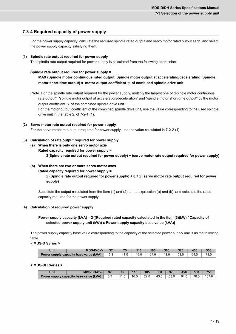
MDS-D/DH Series Specifications Manual
7-3 Selection of the power supply unit
7 - 19
7-3-4 Required capacity of power supply
For the power supply capacity, calculate the required spindle rated output and servo motor rated output each, and select
the power supply capacity satisfying them.
(1) Spindle rate output required for power supply
The spindle rate output required for power supply is calculated from the following expression.
Spindle rate output required for power supply =
MAX (Spindle motor continuous rated output, Spindle motor output at accelerating/decelerating, Spindle
motor short-time output) x motor output coefficient γ of combined spindle drive unit
(Note) For the spindle rate output required for the power supply, multiply the largest one of "spindle motor continuous
rate output", "spindle motor output at acceleration/deceleration" and "spindle motor short-time output" by the motor
output coefficient γ of the combined spindle drive unit.
For the motor output coefficient of the combined spindle drive unit, use the value corresponding to the used spindle
drive unit in the table 2. of 7-2-1 (1).
(2) Servo motor rate output required for power supply
For the servo motor rate output required for power supply, use the value calculated in 7-2-2 (1).
(3) Calculation of rate output required for power supply
(a) When there is only one servo motor axis
Rated capacity required for power supply =
Σ(Spindle rate output required for power supply) + (servo motor rate output required for power supply)
(b) When there are two or more servo motor axes
Rated capacity required for power supply =
Σ (Spindle rate output required for power supply) + 0.7 Σ (servo motor rate output required for power
supply)
Substitute the output calculated from the item (1) and (2) to the expression (a) and (b), and calculate the rated
capacity required for the power supply.
(4) Calculation of required power supply
Power supply capacity (kVA) = Σ(Required rated capacity calculated in the item (3)(kW) / Capacity of
selected power supply unit (kW)) x Power supply capacity base value (kVA)
The power supply capacity base value corresponding to the capacity of the selected power supply unit is as the following
table.
< MDS-D Series >
< MDS-DH Series >
Unit MDS-D-CV- 37 75 110 185 300 370 450 550Power supply capacity base value (kVA) 5.3 11.0 16.0 27.0 43.0 53.0 64.0 78.0
Unit MDS-DH-CV- 37 75 110 185 300 370 450 550 750Power supply capacity base value (kVA) 5.3 11.0 16.0 27.0 43.0 53.0 64.0 78.0 107.0
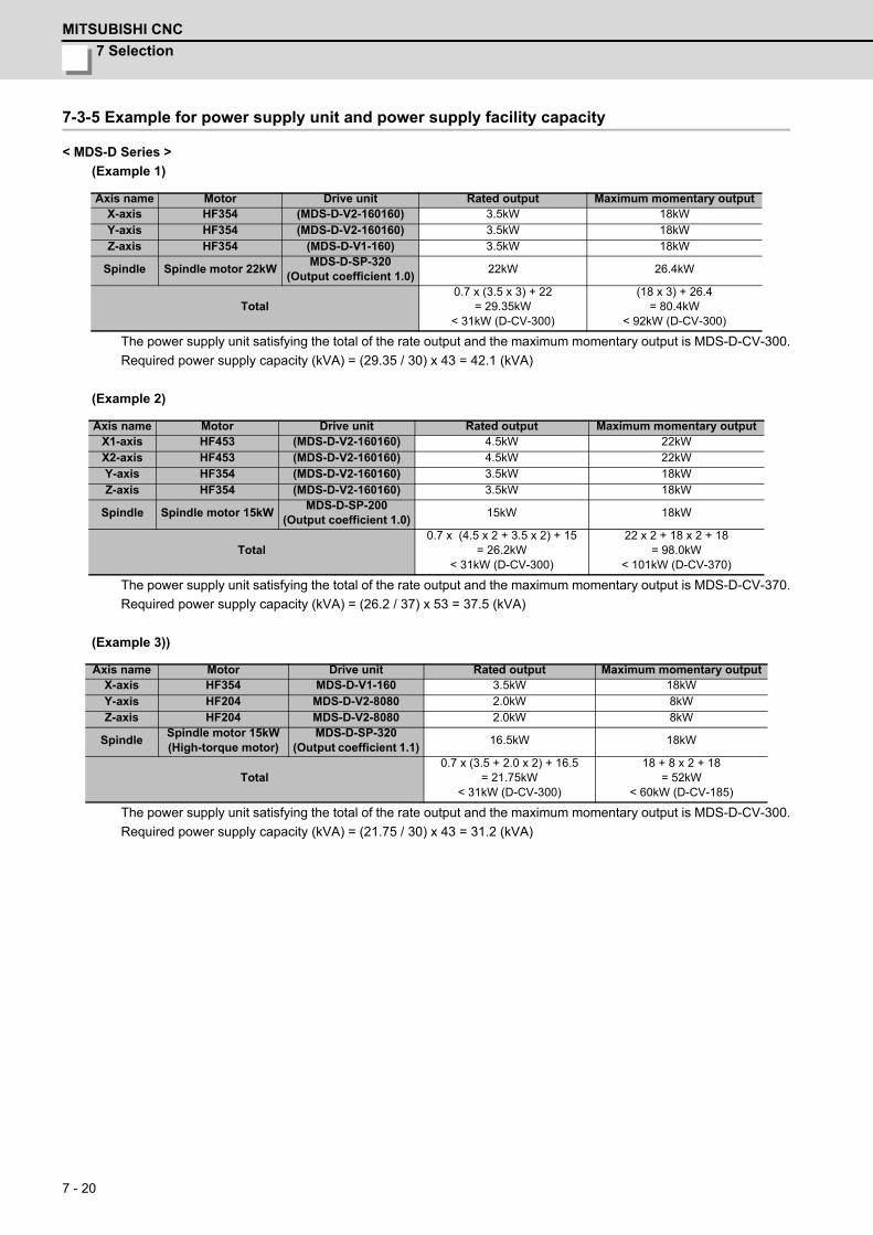
7 Selection
MITSUBISHI CNC
7 - 20
7-3-5 Example for power supply unit and power supply facility capacity
< MDS-D Series >
(Example 1)
The power supply unit satisfying the total of the rate output and the maximum momentary output is MDS-D-CV-300.
Required power supply capacity (kVA) = (29.35 / 30) x 43 = 42.1 (kVA)
(Example 2)
The power supply unit satisfying the total of the rate output and the maximum momentary output is MDS-D-CV-370.
Required power supply capacity (kVA) = (26.2 / 37) x 53 = 37.5 (kVA)
(Example 3))
The power supply unit satisfying the total of the rate output and the maximum momentary output is MDS-D-CV-300.
Required power supply capacity (kVA) = (21.75 / 30) x 43 = 31.2 (kVA)
Axis name Motor Drive unit Rated output Maximum momentary outputX-axis HF354 (MDS-D-V2-160160) 3.5kW 18kWY-axis HF354 (MDS-D-V2-160160) 3.5kW 18kWZ-axis HF354 (MDS-D-V1-160) 3.5kW 18kW
Spindle Spindle motor 22kWMDS-D-SP-320
(Output coefficient 1.0)22kW 26.4kW
Total0.7 x (3.5 x 3) + 22
= 29.35kW< 31kW (D-CV-300)
(18 x 3) + 26.4= 80.4kW
< 92kW (D-CV-300)
Axis name Motor Drive unit Rated output Maximum momentary outputX1-axis HF453 (MDS-D-V2-160160) 4.5kW 22kWX2-axis HF453 (MDS-D-V2-160160) 4.5kW 22kWY-axis HF354 (MDS-D-V2-160160) 3.5kW 18kWZ-axis HF354 (MDS-D-V2-160160) 3.5kW 18kW
Spindle Spindle motor 15kWMDS-D-SP-200
(Output coefficient 1.0)15kW 18kW
Total0.7 x (4.5 x 2 + 3.5 x 2) + 15
= 26.2kW< 31kW (D-CV-300)
22 x 2 + 18 x 2 + 18= 98.0kW
< 101kW (D-CV-370)
Axis name Motor Drive unit Rated output Maximum momentary outputX-axis HF354 MDS-D-V1-160 3.5kW 18kWY-axis HF204 MDS-D-V2-8080 2.0kW 8kWZ-axis HF204 MDS-D-V2-8080 2.0kW 8kW
SpindleSpindle motor 15kW(High-torque motor)
MDS-D-SP-320(Output coefficient 1.1)
16.5kW 18kW
Total0.7 x (3.5 + 2.0 x 2) + 16.5
= 21.75kW< 31kW (D-CV-300)
18 + 8 x 2 + 18= 52kW
< 60kW (D-CV-185)

MDS-D/DH Series Specifications Manual
7-3 Selection of the power supply unit
7 - 21
< MDS-DH Series >
(Example 1)
The power supply unit satisfying the total of the rate output and the maximum momentary output is MDS-DH-CV-
300.
Required power supply capacity (kVA) = (29.35 / 30) x 43 = 42.0 (kVA)
(Example 2)
The power supply unit satisfying the total of the rate output and the maximum momentary output is MDS-DH-CV-
370.
Required power supply capacity (kVA) = (26.2 / 30) x 43 = 37.6 (kVA)
(Example 3)
The power supply unit satisfying the total of the rate output and the maximum momentary output is MDS-DH-CV-
370.
Required power supply capacity (kVA) = (21.75 / 30) x 43 = 31.2 (kVA)
Axis name Motor Drive unit Rated output Maximum momentary outputX-axis HF-H354 (MDS-DH-V2-8080) 3.5kW 18kWY-axis HF-H354 (MDS-DH-V2-8080) 3.5kW 18kWZ-axis HF-H354 (MDS-DH-V1-80) 3.5kW 18kW
Spindle Spindle motor 22kWMDS-DH-SP-160(Output 22kW)
22kW 26.4kW
Total0.7×(3.5×3)+22
=29.35kW<31kW(DH-CV-300)
(18×3)+26.4=80.4kW
<92kW(DH-CV-300)
Axis name Motor Drive unit Rated output Maximum momentary outputX1-axis HF-H453 (MDS-DH-V2-8080) 4.5kW 22kWX2-axis HF-H453 (MDS-DH-V2-8080) 4.5kW 22kWY-axis HF-H354 (MDS-DH-V2-8080) 3.5kW 18kWZ-axis HF-H354 (MDS-DH-V2-8080) 3.5kW 18kW
Spindle Spindle motor 15kWMDS-DH-SP-100
(Output coefficient 1.0)15kW 18kW
Total0.7×(4.5×2+3.5×2)+15
=26.2kW<31kW(DH-CV-300)
22×2+18×2+18=98.0kW
<101kW(DH-CV-370)
Axis name Motor Drive unit Rated output Maximum momentary outputX-axis HF-H354 MDS-DH-V1-160 3.5kW 18kWY-axis HF-H204 MDS-DH-V2-8080 2.0kW 8kWZ-axis HF-H204 MDS-DH-V2-8080 2.0kW 8kW
SpindleSpindle motor 15kW(High-torque motor)
MDS-DH-SP-320(Output coefficient 1.1)
16.5kW 18kW
Total0.7×(3.5+2.0×2)+16.5
=21.75kW<31kW(DH-CV-300)
18+8×2+18=52kW
<60kW(DH-CV-185)

7 Selection
MITSUBISHI CNC
7 - 22

Appendix 1 - 1
Appendix 1
Cable and Connector Specifications

Appendix 1 Cable and Connector Specifications
MITSUBISHI CNC
Appendix 1 - 2
Appendix 1-1 Selection of cableAppendix 1-1-1 Cable wire and assembly
(1) Cable wire
The specifications of the wire used for each cable, and the machining methods are shown in this section. When
manufacturing the encoder cable and battery connection cable, use the recommended wires shown below or equivalent
products.
(a) Heat resistant specifications cable
(b) General-purpose heat resistant specifications cable
(Note 1) Bando Electric Wire (http://www.bew.co.jp/)
(Note 2) The Mitsubishi standard cable is the (a) Heat resistant specifications cable. For MDS-C1/CH series, (b) or
equivalent is used as the standard cable.
Core identification
Wire type(other
manufacturer's product)
Finish outer
diameter
Sheath material
No. of pairs
Wire characteristics
Configura-tion
Conductive resistor
Withstandvoltage
Insulationresistance
Heat resistance
temperatureFlexibility
BD20288Compound 6-pair shielded cable Specification No. Bangishi-17145(Note 1)
8.7mmHeat
resistant PVC
2
(0.5mm2)
100 strands/0.08mm
40.7Ω/kmor less
500VAC/1min
1000MΩ/kmor more
105°C
70×104 times
or more at R200
4
(0.2mm2)40 strands/
0.08mm103Ω/kmor less
Wire type(other
manufacturer's product)
Finish outer
diameter
Sheath material
No. of pairs
Wire characteristics
Configura-tion
Conductiveresistor
Withstandvoltage
Insulation resistance
Heat resistance
temperatureFlexibility
BD20032Compound 6-pair shielded cable Specification No. Bangishi-16903 Revision No. 3(Note 2))
8.7mm PVC
2
(0.5mm2)100strands/
0.08mm40.7Ω/km
or less
500VAC/1min
1000MΩ/kmor more
60°C
100×104 times
or more at R200
4
(0.2mm2)40strands/0.08mm
103Ω/kmor less
Pair No.Insulator colorL1 L2
A1 (0.5mm2) Red White
A2 (0.5mm2) Black White
B1 (0.2mm2) Brown Orange
B2 (0.2mm2) Blue Green
B3 (0.2mm2) Purple White
B4 (0.2mm2) Yellow White
A1
A2 B2
B1 B4
B3
L2 L1
Sheath
Mesh shield
Intervening wire
Tape
Compound 6-pair cable structure drawing
Cable core
InsulatorConductor
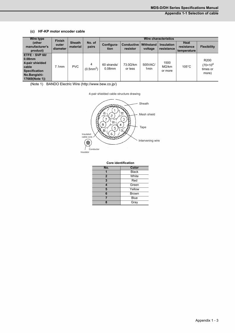
MDS-D/DH Series Specifications Manual
Appendix 1-1 Selection of cable
Appendix 1 - 3
(c) HF-KP motor encoder cable
(Note 1) BANDO Electric Wire (http://www.bew.co.jp/)
Core identification
Wire type(other
manufacturer's product)
Finish outer
diameter
Sheath material
No. of pairs
Wire characteristics
Configura-tion
Conductiveresistor
Withstandvoltage
Insulation resistance
Heat resistance
temperatureFlexibility
ETFE・SVP 60/0.08mm4-pair shielded cable Specification No.Bangishi-17669(Note 1))
7.1mm PVC4
(0.5mm2)60 strands/
0.08mm73.0Ω/km
or less500VAC/
1min
1500MΩ/kmor more
105°C
R200
(70×104 times or more)
No. Color1 Black2 White3 Red4 Green5 Yellow6 Brown7 Blue8 Gray
Sheath
Mesh shield
Intervening wire
Tape
4-pair shielded cable structure drawing
InsulatorConductor
Insulated cable core
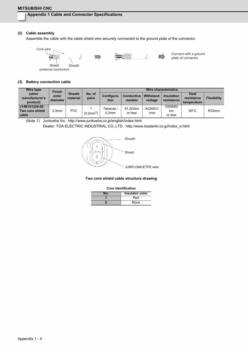
Appendix 1 Cable and Connector Specifications
MITSUBISHI CNC
Appendix 1 - 4
(2) Cable assembly
Assemble the cable with the cable shield wire securely connected to the ground plate of the connector.
(3) Battery connection cable
(Note 1) Junkosha Inc. http://www.junkosha.co.jp/english/index.html
Dealer: TOA ELECTRIC INDUSTRIAL CO.,LTD. http://www.toadenki.co.jp/index_e.html
Two core shield cable structure drawing
Core identification
Wire type (other
manufacturer's product)
Finish outer
diameter
Sheath material
No. of pairs
Wire characteristics
Configura-tion
Conductiveresistor
Withstand voltage
Insulation resistance
Heat resistance
temperatureFlexibility
J14B101224-00Two core shield cable
3.3mm PVC1
(0.2mm2)7strands /
0.2mm91.2Ω/km
or lessAC500V/
1min
1000MΩ/km
or less80°C R33mm
No. Insulator color1 Red2 Black
Core wire
Shield(external conductor)
Sheath
Connect with a ground plate of connector.
1
2
JUNFLON ETFE wire
Sheath
Shield
R
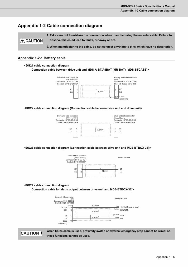
MDS-D/DH Series Specifications Manual
Appendix 1-2 Cable connection diagram
Appendix 1 - 5
Appendix 1-2 Cable connection diagram
Appendix 1-2-1 Battery cable
<DG21 cable connection diagram
(Connection cable between drive unit and MDS-A-BT/A6BAT (MR-BAT) (MDS-BTCASE)>
<DG22 cable connection diagram (Connection cable between drive unit and drive unit)>
<DG23 cable connection diagram (Connection cable between drive unit and MDS-BTBOX-36)>
<DG24 cable connection diagram
(Connection cable for alarm output between drive unit and MDS-BTBOX-36)>
1. Take care not to mistake the connection when manufacturing the encoder cable. Failure to
observe this could lead to faults, runaway or fire.
2. When manufacturing the cable, do not connect anything to pins which have no description.
When DG24 cable is used, proximity switch or external emergency stop cannot be wired, so
these functions cannot be used.
CAUTION
12
9 1 PE
BTLG
BT LG
0.2mm2
Drive unit side connector
Connector: DF1B-2S-2.5RContact: DF1B-2428SCA
Battery unit side connector
Connector: 10120-3000VEShell kit: 10320-52F0-008
Casegrounding
(Hirose Electric) (3M)
12
1 2
BTLG
BT LG
0.2mm2
Drive unit side connector
Connector: DF1B-2S-2.5RContact: DF1B-2428SCA
Drive unit side connector
Connector: DF1B-2S-2.5RContact: DF1B-2428SCA
(Hirose Electric) (Hirose Electric)
1 2
BTLG
BTLG0.2mm2
: DF1B-2S-2.5R: DF1B-2428SCA
Battery box sideDrive unit side connector
Connector Contact
(Hirose Electric)
20 13
4 1
FG
DICOMD11
P5LG
DO(ALM)
+5VLG0.2mm2
:10120-3000VE:10320-52F0-008
0.2mm2
0.2mm2 +24V (I/O power side)
Casegrounding
Drive unit side connector
ConnectorShell kit
Battery box side(3M)
Blue
Light blue
Yellow
White
CAUTION
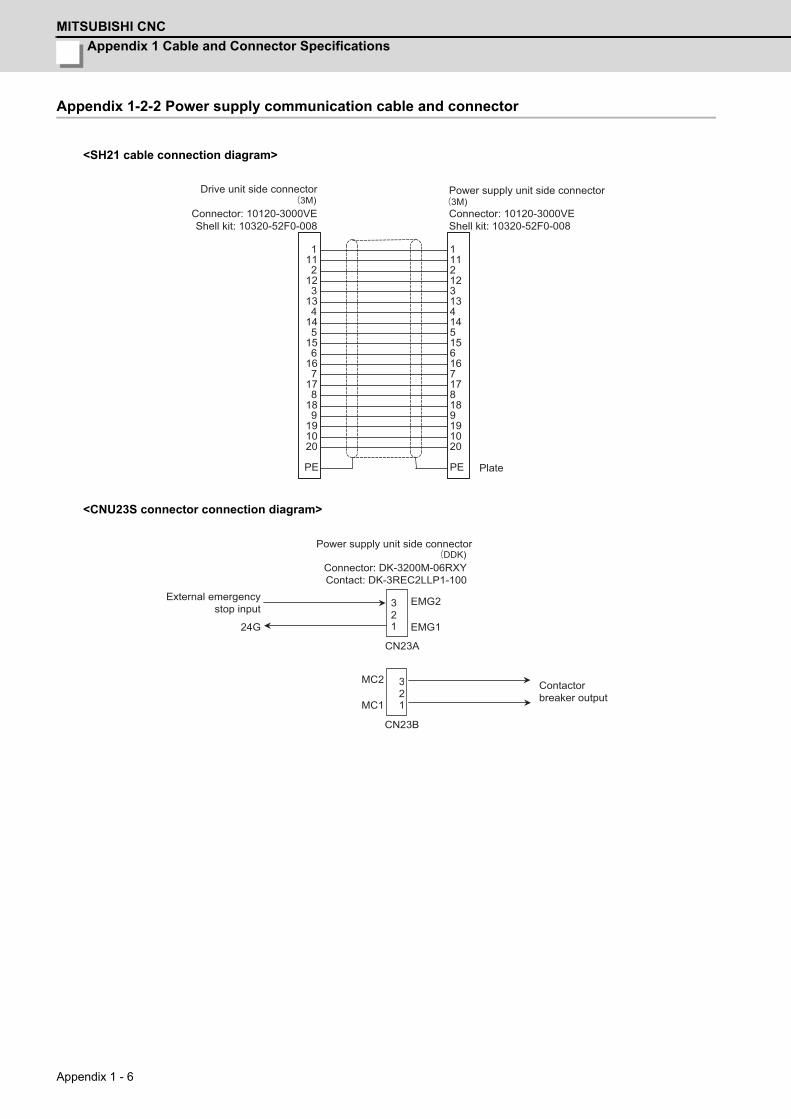
Appendix 1 Cable and Connector Specifications
MITSUBISHI CNC
Appendix 1 - 6
Appendix 1-2-2 Power supply communication cable and connector
<SH21 cable connection diagram>
<CNU23S connector connection diagram>
1 11 2 12 3 13 4 14 5 15 6 16 7 17 8 18 9 19 10 20
PE
1
112
123
134
145
156
167
178
189
191020
PE
Drive unit side connector
Connector: 10120-3000VEShell kit: 10320-52F0-008
Power supply unit side connector
Connector: 10120-3000VEShell kit: 10320-52F0-008
Plate
(3M) (3M)
3
1
CN23A
EMG2 EMG1
3
1
CN23B
MC2
MC1
24G 2
2
External emergencystop input
Power supply unit side connector
Connector: DK-3200M-06RXYContact: DK-3REC2LLP1-100
Contactorbreaker output
(DDK)
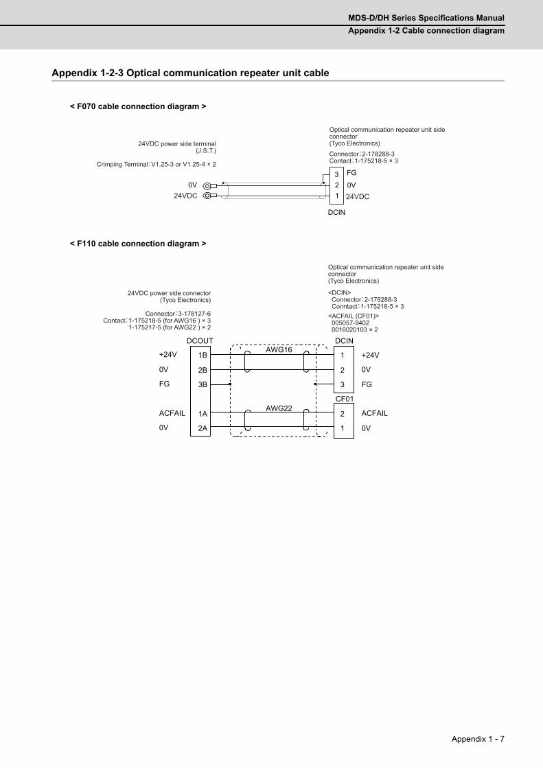
MDS-D/DH Series Specifications Manual
Appendix 1-2 Cable connection diagram
Appendix 1 - 7
Appendix 1-2-3 Optical communication repeater unit cable
< F070 cable connection diagram >
< F110 cable connection diagram >
DCIN
0V
FG
123
0V
Optical communication repeater unit side connector(Tyco Electronics)24VDC power side terminal
(J.S.T.)
Crimping Terminal:V1.25-3 or V1.25-4 × 2
24VDC24VDC
Connector:2-178288-3Contact:1-175218-5 × 3
+24V
0V
FG
ACFAIL
0V
1B
2B
3B
1A
2A
1
2
3
2
1
+24V
0V
FG
ACFAIL
0V
AWG16
AWG22
DCOUT DCIN
CF01
<ACFAIL (CF01)> 005057-9402 0016020103 × 2
24VDC power side connector(Tyco Electronics)
Connector:3-178127-6Contact:1-175218-5 (for AWG16 ) × 3
1-175217-5 (for AWG22 ) × 2
Optical communication repeater unit side connector(Tyco Electronics)
<DCIN> Connector:2-178288-3 Conntact:1-175218-5 × 3

Appendix 1 Cable and Connector Specifications
MITSUBISHI CNC
Appendix 1 - 8
Appendix 1-2-4 Servo / tool spindle encoder cable
<CNV2E-8P, CNV2E-9P cable connection diagram>
<For 15m or less>
<For 15m to 30m>
12
97834
PE
8 5 3 4 6 7 1 2 10
P5(+5V)LG
BTSD
SD*RQ
RQ*
P5(+5V) LG CNT BT SD SD* RQ RQ* SHD
0.5mm2
0.2mm2
0.2mm2
0.2mm2
Drive unit side connector(3M)
Receptacle: 36210-0100PLShell kit: 36310-3200-008
(MOLEX)Connector set: 54599-1019
Casegrounding
Motor encoder/Ball screw side encoder side connector
Plug: CMV1-SP10S-M2 (Straight)CMV1-AP10S-M2 (Angle)
Contact: CMV1-#22ASC-S1
(DDK)
12
97834
PE
8 5 3 4 6 7 1 2 10
P5(+5V)LG
BTSD
SD*RQ
RQ*
P5(+5V) LG CNT BT SD SD* RQ RQ* SHD
0.5mm2
0.2mm2
0.5mm2
0.2mm2
0.2mm2
Drive unit side connector(3M)
Receptacle: 36210-0100PLShell kit: 36310-3200-008
(MOLEX)Connector set: 54599-1019
Casegrounding
Motor encoder/Ball screw side encoder side connector
Plug: CMV1-SP10S-M2 (Straight)CMV1-AP10S-M2 (Angle)
Contact: CMV1-#22ASC-S1
(DDK)
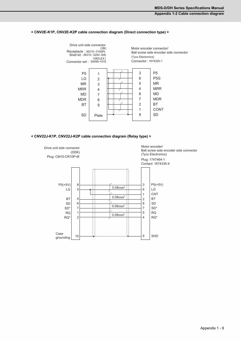
MDS-D/DH Series Specifications Manual
Appendix 1-2 Cable connection diagram
Appendix 1 - 9
< CNV2E-K1P, CNV2E-K2P cable connection diagram (Direct connection type) >
< CNV22J-K1P, CNV22J-K2P cable connection diagram (Relay type) >
365487219
P5LGMR
MRRMD
MDRBT
SD
P5P5GMRMRRMDMDRBTCONTSD
1234789
Plate
(3M)
: 36210 - 0100PL : 36310 - 3200- 008
( ) : 54599-1019
Drive unit side connector
ReceptacleShell kit
MOLEXConnector set
Motor encoder connector/
(Tyco Electronics)Connector : 1674320-1
Ball screw side encoder side connector
8 5
4 6 7 1 2
361287 54 910
BT SD
SD* RQ
RQ*
CNT BT SD SD* RQ RQ* SHD
0.08mm2
0.08mm2
0.08mm2
0.08mm2
P5(+5V)LG
P5(+5V)LG
Drive unit side connector
Casegrounding
Motor encoder/Ball screw side encoder side connector
Plug: 1747464-1Contact: 1674335-4
Plug: CM10-CR10P-M(DDK) (Tyco Electronics)
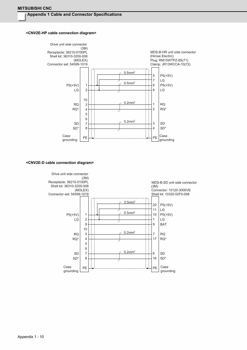
Appendix 1 Cable and Connector Specifications
MITSUBISHI CNC
Appendix 1 - 10
<CNV2E-HP cable connection diagram>
<CNV2E-D cable connection diagram>
1 2
10 3 4 5 6 7 8
PE
5 7 6 8 1 2 3 4 PE
P5(+5V)LG
RQRQ*
SDSD*
P5(+5V) LG P5(+5V) LG RQ RQ* SD SD*
0.5mm2
0.5mm2
0.2mm2
0.2mm2
Drive unit side connector(3M)
Receptacle: 36210-0100PLShell kit: 36310-3200-008
(MOLEX)Connector set: 54599-1019
MDS-B-HR unit side connector
Plug: RM15WTPZ-8S(71)Clamp: JR13WCCA-10(72)
Casegrounding
Casegrounding
(Hirose Electric)
1 2 9
10 3 4 5 6 7 8
PE
20 11 10 1 9 7 17 6 16 PE
P5(+5V)LG
RQRQ*
SDSD*
P5(+5V) LG P5(+5V) LG BAT RQ RQ* SD SD*
0.5mm2
0.5mm2
0.2mm2
0.2mm2
Drive unit side connector(3M)
Receptacle: 36210-0100PLShell kit: 36310-3200-008
(MOLEX)Connector set: 54599-1019
MDS-B-SD unit side connector
Connector: 10120-3000VEShell kit: 10320-52F0-008
Casegrounding
Casegrounding
(3M)
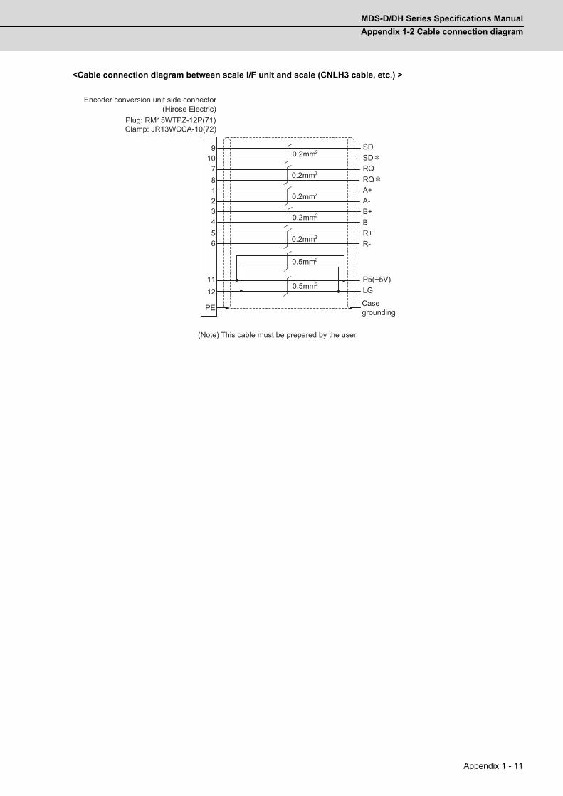
MDS-D/DH Series Specifications Manual
Appendix 1-2 Cable connection diagram
Appendix 1 - 11
<Cable connection diagram between scale I/F unit and scale (CNLH3 cable, etc.) >
9
10 7
8
1
2
3
4
5
6
11
12
PE
0.5mm2
0.5mm2
0.2mm2
0.2mm2
0.2mm2
0.2mm2
0.2mm2R-R+B-
SDSD*
RQ*RQ
A-A+
B+
P5(+5V)LG
Encoder conversion unit side connector
Plug: RM15WTPZ-12P(71)Clamp: JR13WCCA-10(72)
Casegrounding
(Note) This cable must be prepared by the user.
(Hirose Electric)

Appendix 1 Cable and Connector Specifications
MITSUBISHI CNC
Appendix 1 - 12
<Rectangular wave communication encoder (linear scale, etc.) cable connection diagram>
(Note) This cable must be prepared by the user.
<Serial communication encoder (linear scale, etc.) cable connection diagram>
(Note) This cable must be prepared by the user.
For compatible encoder, refer to the section "Servo option" in Specifications Manual.
12103456789
PE
P5(+5V)LG
ABZSEL*AA*BB*ZZ*
P5(+5V)LG
AA*BB*ZZ*
SHD
0.5mm2
0.5mm2
0.2mm2
0.2mm2
0.2mm2
Drive unit side connector
(3M)Receptacle: 36210-0100PL
Shell kit: 36310-3200-008(MOLEX)
Connector set: 54599-1019
Casegrounding
Contact the encoder manufacturefor the details.
(Note) Contact the encoder manufacture about whether to perform the P5V wiring or not.
Machine side rectangular wave communication encoder
1 29
10345678
PE
P5(+5V)LG
RQRQ*
SDSD*
P5(+5V) LG RQ RQ* SD SD* SHD
0.5mm2
0.5mm2
0.2mm2
0.2mm2
Drive unit side connector
(3M)Receptacle: 36210-0100PL
Shell kit: 36310-3200-008(MOLEX)
Connector set: 54599-1019
Casegrounding
Contact the encoder manufacture for the details.
(Note) Contact the encoder manufacture about whether to perform the P5V wiring or not.
Machine side serial communication encoder
Note: When using a linear scale manufactured by FAGOR, ground the encoder side SEL signal to LG.
POINT
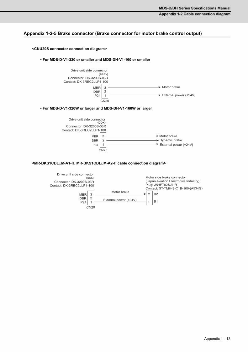
MDS-D/DH Series Specifications Manual
Appendix 1-2 Cable connection diagram
Appendix 1 - 13
Appendix 1-2-5 Brake connector (Brake connector for motor brake control output)
<CNU20S connector connection diagram>
• For MDS-D-V1-320 or smaller and MDS-DH-V1-160 or smaller
• For MDS-D-V1-320W or larger and MDS-DH-V1-160W or larger
<MR-BKS1CBLM-A1-H, MR-BKS1CBLM-A2-H cable connection diagram>
3 2 1
CN20
MBRDBRP24
Drive unit side connector
Connector: DK-3200S-03RContact: DK-3REC2LLP1-100
External power (+24V)
Motor brake
(DDK)
1 2 3
CN20
MBRDBRP24
Drive unit side connector
Connector: DK-3200S-03RContact: DK-3REC2LLP1-100
External power (+24V)
Motor brakeDynamic brake
(DDK)
3 2 1
CN20
MBRDBRP24 1
2
B1
B2
Motor side brake connector(Japan Aviation Electronics Industry)Plug: JN4FT02SJ1-RContact: ST-TMH-S-C1B-100-(A534G)
Drive unit side connector
Connector: DK-3200S-03RContact: DK-3REC2LLP1-100
External power (+24V)
Motor brake
(DDK)

Appendix 1 Cable and Connector Specifications
MITSUBISHI CNC
Appendix 1 - 14
Appendix 1-2-6 Spindle encoder cable
<CNP2E-1 cable connection diagram>
<For 15m or less>
<For 15m to 30m>
12
56
7834
PE
7 8 2 1 5 6 3 4 9
P5(+5V)LG
MT1MT2
SDSD*RQ
RQ*
P5(+5V) LG MT1 MT2 SD SD* RQ RQ* SHD
0.5mm2
0.2mm2
0.2mm2
0.2mm2
Spindle drive unit side connector(3M)
Receptacle: 36210-0100PLShell kit: 36310-3200-008
(MOLEX)Connector set: 54599-1019
Casegrounding
(Note) For the pin "7" or "8", use the contact "170364-1". For the other pins, use the contact "170363-1".
(Note)
Spindle motor side connector
Connector: 172169-1Contact: 170363-1(AWG26-22) 170364-1(AWG22-18)
(Tyco Electronics)
12
56
7834
PE
7
8 2 1 5 6 3 4 9
P5(+5V)LG
MT1MT2
SDSD*RQ
RQ*
P5(+5V) LG MT1 MT2 SD SD* RQ RQ* SHD
0.5mm2
0.2mm2
0.2mm2
0.2mm2
0.5mm2
Spindle drive unit side connector(3M)
Receptacle: 36210-0100PLShell kit: 36310-3200-008
(MOLEX)Connector set: 54599-1019
Casegrounding
(Note) For the pin "7" or "8", use the contact "170364-1". For the other pins, use the contact "170363-1".
(Note)
Spindle motor side connector
Connector: 172169-1Contact: 170363-1(AWG26-22) 170364-1(AWG22-18)
(Tyco Electronics)
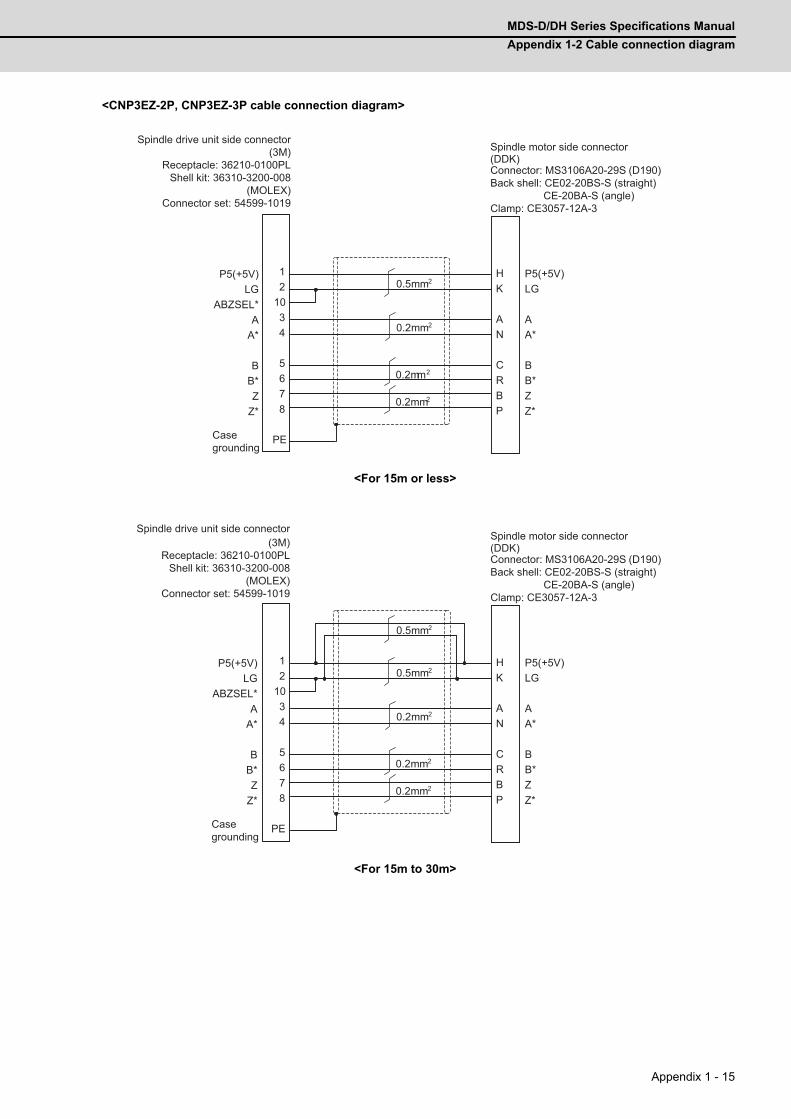
MDS-D/DH Series Specifications Manual
Appendix 1-2 Cable connection diagram
Appendix 1 - 15
<CNP3EZ-2P, CNP3EZ-3P cable connection diagram>
<For 15m or less>
<For 15m to 30m>
12
1034
5 678
PE
H
K A N C R B P
P5(+5V)LG
ABZSEL*A
A*
BB*Z
Z*
P5(+5V) LG A A* B B* Z Z*
0.5mm2
0.2mm2
0.2mm2
0.2mm2
Spindle drive unit side connector(3M)
Receptacle: 36210-0100PLShell kit: 36310-3200-008
(MOLEX)Connector set: 54599-1019
Casegrounding
Spindle motor side connector
Connector: MS3106A20-29S (D190)Back shell: CE02-20BS-S (straight) CE-20BA-S (angle)Clamp: CE3057-12A-3
(DDK)
12
1034
5678
PE
H
K A N C R B P
P5(+5V)LG
ABZSEL*A
A*
BB*Z
Z*
P5(+5V) LG A A* B B* Z Z*
0.5mm2
0.2mm2
0.2mm2
0.2mm2
0.5mm2
Spindle drive unit side connector(3M)
Receptacle: 36210-0100PLShell kit: 36310-3200-008
(MOLEX)Connector set: 54599-1019
Casegrounding
Spindle motor side connector
Connector: MS3106A20-29S (D190)Back shell: CE02-20BS-S (straight) CE-20BA-S (angle)Clamp: CE3057-12A-3
(DDK)
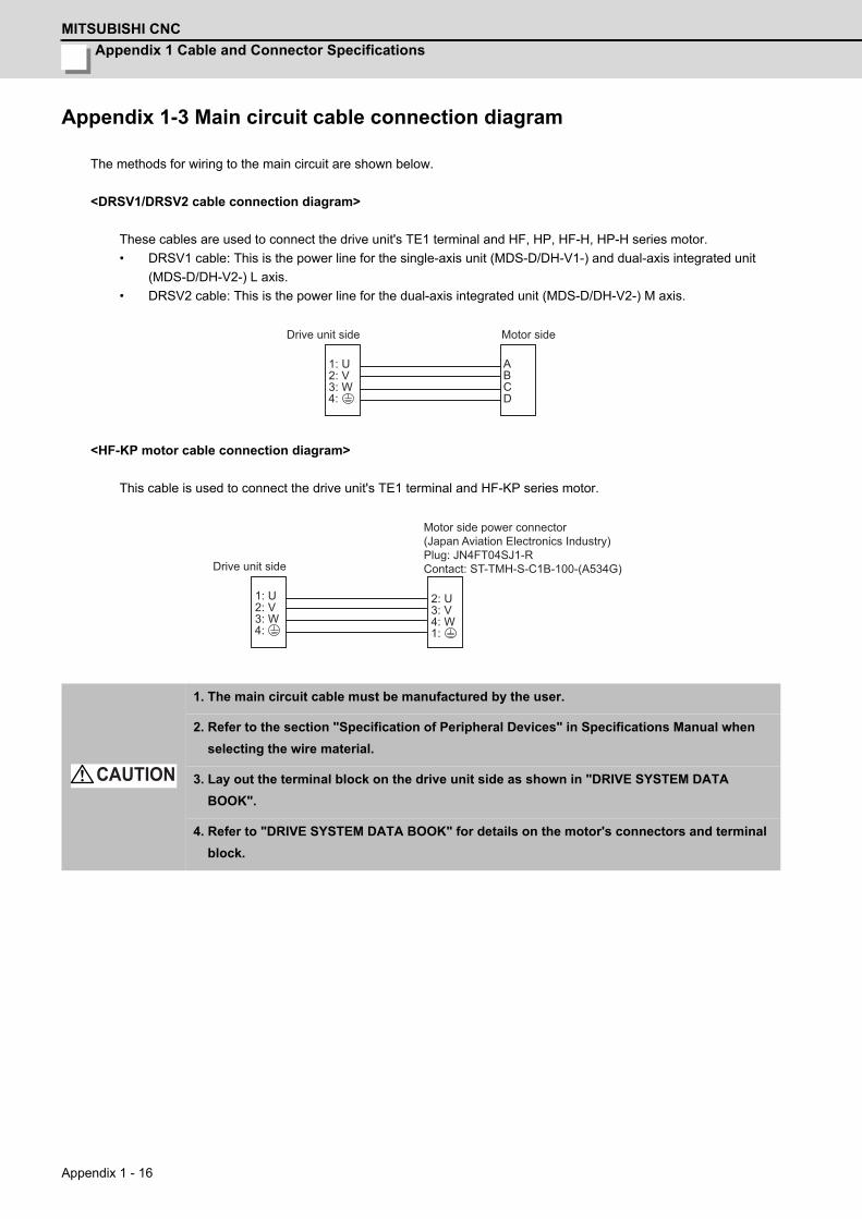
Appendix 1 Cable and Connector Specifications
MITSUBISHI CNC
Appendix 1 - 16
Appendix 1-3 Main circuit cable connection diagram
The methods for wiring to the main circuit are shown below.
<DRSV1/DRSV2 cable connection diagram>
These cables are used to connect the drive unit's TE1 terminal and HF, HP, HF-H, HP-H series motor.
• DRSV1 cable: This is the power line for the single-axis unit (MDS-D/DH-V1-) and dual-axis integrated unit
(MDS-D/DH-V2-) L axis.
• DRSV2 cable: This is the power line for the dual-axis integrated unit (MDS-D/DH-V2-) M axis.
<HF-KP motor cable connection diagram>
This cable is used to connect the drive unit's TE1 terminal and HF-KP series motor.
1. The main circuit cable must be manufactured by the user.
2. Refer to the section "Specification of Peripheral Devices" in Specifications Manual when
selecting the wire material.
3. Lay out the terminal block on the drive unit side as shown in "DRIVE SYSTEM DATA
BOOK".
4. Refer to "DRIVE SYSTEM DATA BOOK" for details on the motor's connectors and terminal
block.
1: U 2: V 3: W 4:
A B C D
Drive unit side Motor side
1: U 2: V 3: W 4:
2: U 3: V 4: W 1:
Motor side power connector(Japan Aviation Electronics Industry)Plug: JN4FT04SJ1-RContact: ST-TMH-S-C1B-100-(A534G)Drive unit side
CAUTION
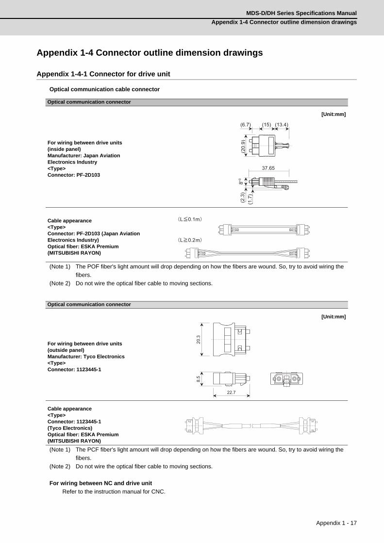
MDS-D/DH Series Specifications Manual
Appendix 1-4 Connector outline dimension drawings
Appendix 1 - 17
Appendix 1-4 Connector outline dimension drawings
Appendix 1-4-1 Connector for drive unit
Optical communication cable connector
(Note 1) The POF fiber's light amount will drop depending on how the fibers are wound. So, try to avoid wiring the
fibers.
(Note 2) Do not wire the optical fiber cable to moving sections.
(Note 1) The PCF fiber's light amount will drop depending on how the fibers are wound. So, try to avoid wiring the
fibers.
(Note 2) Do not wire the optical fiber cable to moving sections.
For wiring between NC and drive unit
Refer to the instruction manual for CNC.
Optical communication connector
For wiring between drive units (inside panel)Manufacturer: Japan Aviation Electronics Industry<Type>Connector: PF-2D103
[Unit:mm]
Cable appearance<Type>Connector: PF-2D103 (Japan Aviation Electronics Industry)Optical fiber: ESKA Premium(MITSUBISHI RAYON)
Optical communication connector
For wiring between drive units (outside panel)Manufacturer: Tyco Electronics<Type>Connector: 1123445-1
[Unit:mm]
Cable appearance<Type>Connector: 1123445-1(Tyco Electronics)Optical fiber: ESKA Premium(MITSUBISHI RAYON)
(13.4) (15) (6.7)
(20.
9)8+0
37.65
(2.3
)(1
.7)
L 0.1
L 0.2
m
m
22.7
8.5
20
.3
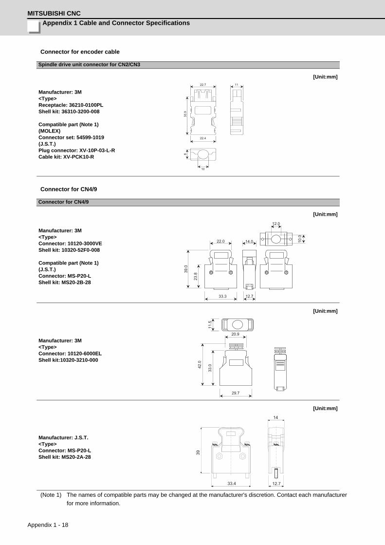
Appendix 1 Cable and Connector Specifications
MITSUBISHI CNC
Appendix 1 - 18
Connector for encoder cable
Connector for CN4/9
(Note 1) The names of compatible parts may be changed at the manufacturer's discretion. Contact each manufacturer
for more information.
Spindle drive unit connector for CN2/CN3
Manufacturer: 3M<Type>Receptacle: 36210-0100PLShell kit: 36310-3200-008 Compatible part (Note 1)(MOLEX)Connector set: 54599-1019(J.S.T.)Plug connector: XV-10P-03-L-RCable kit: XV-PCK10-R
[Unit:mm]
Connector for CN4/9
Manufacturer: 3M<Type>Connector: 10120-3000VEShell kit: 10320-52F0-008 Compatible part (Note 1)(J.S.T.)Connector: MS-P20-LShell kit: MS20-2B-28
[Unit:mm]
Manufacturer: 3M<Type>Connector: 10120-6000ELShell kit:10320-3210-000
[Unit:mm]
Manufacturer: J.S.T.<Type>Connector: MS-P20-LShell kit: MS20-2A-28
[Unit:mm]
22.4
8
10
11
33.9
22.7
33.3
22.0
39.0
23.8
14.0
12.7
12.0
10.0
11.5
20.9
33.0
42.0
29.7
14
12.733.4
39
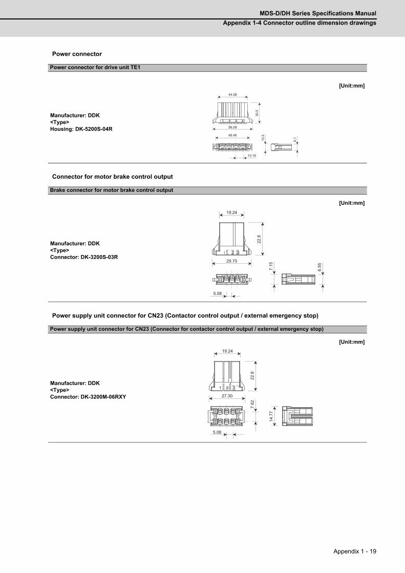
MDS-D/DH Series Specifications Manual
Appendix 1-4 Connector outline dimension drawings
Appendix 1 - 19
Power connector
Connector for motor brake control output
Power supply unit connector for CN23 (Contactor control output / external emergency stop)
Power connector for drive unit TE1
Manufacturer: DDK<Type>Housing: DK-5200S-04R
[Unit:mm]
Brake connector for motor brake control output
Manufacturer: DDK<Type>Connector: DK-3200S-03R
[Unit:mm]
Power supply unit connector for CN23 (Connector for contactor control output / external emergency stop)
Manufacturer: DDK<Type>Connector: DK-3200M-06RXY
[Unit:mm]
48.48
10.16
9.1
10.5
44.08
56.08
30.5
22.8
29.70
19.24
6.55
7.15
5.08
7.62
5.08
14.7
7
19.24
27.30
22.8

Appendix 1 Cable and Connector Specifications
MITSUBISHI CNC
Appendix 1 - 20
Battery power input connector
Battery connector for drive unit
Manufacturer: Hirose Electric<Type>Connector: DF1B-2S-2.5R
[Unit:mm]
11.5
4.4
1.6
1.
9
5.0
2.5
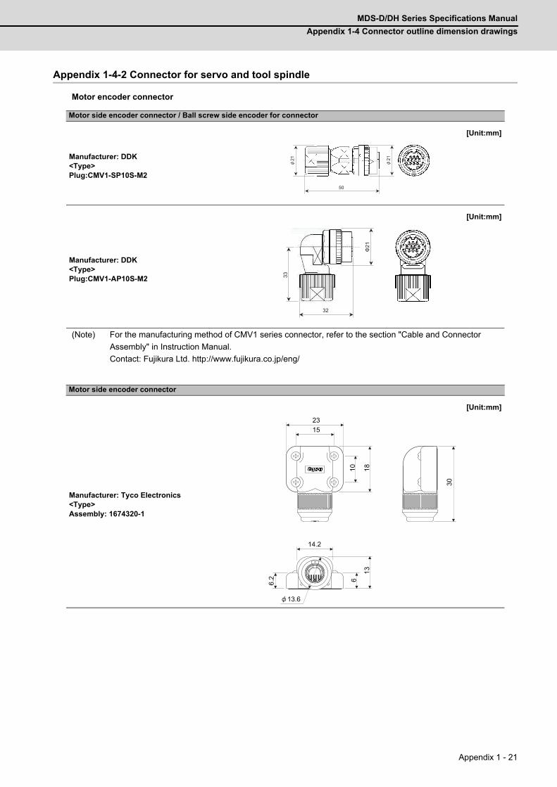
MDS-D/DH Series Specifications Manual
Appendix 1-4 Connector outline dimension drawings
Appendix 1 - 21
Appendix 1-4-2 Connector for servo and tool spindle
Motor encoder connector
(Note) For the manufacturing method of CMV1 series connector, refer to the section "Cable and Connector
Assembly" in Instruction Manual.
Contact: Fujikura Ltd. http://www.fujikura.co.jp/eng/
Motor side encoder connector / Ball screw side encoder for connector
Manufacturer: DDK<Type>Plug:CMV1-SP10S-M2
[Unit:mm]
Manufacturer: DDK<Type>Plug:CMV1-AP10S-M2
[Unit:mm]
Motor side encoder connector
Manufacturer: Tyco Electronics<Type>Assembly: 1674320-1
[Unit:mm]
21 21
50
32
Φ21
33
15
10 18
23
6.2 6
14.2
13
13.6
30
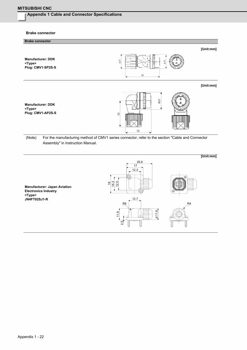
Appendix 1 Cable and Connector Specifications
MITSUBISHI CNC
Appendix 1 - 22
Brake connector
(Note) For the manufacturing method of CMV1 series connector, refer to the section "Cable and Connector
Assembly" in Instruction Manual.
Brake connector
Manufacturer: DDK<Type>Plug: CMV1-SP2S-S
[Unit:mm]
Manufacturer: DDK<Type>Plug: CMV1-AP2S-S
[Unit:mm]
Manufacturer: Japan Aviation Electronics Industry<Type>JN4FT02SJ1-R
[Unit:mm]
21 21
50
32
Φ21
33
26.617
12.3
19 14.3
12.5
12.7
11.8
2.5
R6
11.6
R4

MDS-D/DH Series Specifications Manual
Appendix 1-4 Connector outline dimension drawings
Appendix 1 - 23
Motor power connector
Plug:
Plug:
Clamp:
Motor power connector
Manufacturer: DDK
[Unit:mm]
Type A B+0
C±0.8 D or less W-0.38
CE05-6A18-10SD-C-BSS 11/8-18UNEF-2B 34.13 32.1 57 1-20UNEF-2A
CE05-6A22-22SD-C-BSS 13/8-18UNEF-2B 40.48 38.3 61 13/16-18UNEF-2A
CE05-6A32-17SD-C-BSS 2-18UNS-2B 56.33 54.2 79 13/4-18UNS-2A
Manufacturer: DDK
[Unit:mm]
Type A B+0
D or less W R±0.7 U±0.7 (S)±1 Y or more-0.38
CE05-8A18-10SD-C-BAS 11/8-18UNEF-2B 34.13 69.5 1-20UNEF-2A 13.2 30.2 43.4 7.5
CE05-8A22-22SD-C-BAS 13/8-18UNEF-2B 40.48 75.5 13/16-18UNEF-2A 16.3 33.3 49.6 7.5
CE05-8A32-17SD-C-BAS 2-18UNS-2B 56.33 93.5 13/4-18UNS-2A 24.6 44.5 61.9 8.5
Manufacturer: DDK
[Unit:mm]
TypeShell size
Total length
A
Outer dia.B
Avail. screw length
C
D E F G HFitting screw
VBushing
Applicable cable
CE3057-10A-1(D240) 18 23.8 30.1 10.3 41.3 15.9 14.1 31.7 3.2 1-20UNEF-2B CE3420-10-1 Φ10.5 to Φ14.1
CE3057-12A-1(D240) 20 23.8 35 10.3 41.3 19 16.0 37.3 4 13/16-18UNEF-2B CE3420-12-1 Φ12.5 to Φ16.0
CE3057-20A-1(D240) 32 27.8 51.6 11.9 43 31.7 23.8 51.6 6.3 13/4-18UNS-2B CE3420-20-1 Φ22.0 to Φ23.8
W A
C±
0.8
-0.3
8 +0
B
D or less
7.85 or more
R±0
.7
U±
0.7 S
±1
W
A
-0.3
8 +0
B
D or less
Y or
m
ore
E
H
G±
0.7
C A
1.6
F
D
B±
0.7
(Movable range of one side)
(Inner diameter of cable clamp)(Bus
hing
inne
rdi
amet
er)
V screw

Appendix 1 Cable and Connector Specifications
MITSUBISHI CNC
Appendix 1 - 24
MDS-B-HR connector
Appendix 1-4-3 Connector for spindle
Motor encoder connector
Motor power connector
Manufacturer: Japan Aviation Electronics Industry<Type>JN4FT04SJ1-R
[Unit:mm]
MDS-B-HR connector
Manufacturer: Hirose Electric<Type>Plug:RM15WTPZ-8S(71) (for CON1,2)RM15WTPZ-12P(71) (for CON3)RM15WTPZ-10P(71) (for CON4)
[Unit:mm]
Manufacturer: Hirose Electric<Type>Clamp: JR13WCCA-10(72)
[Unit:mm]
Motor side PLG (TS5690) connector
Manufacturer: Tyco Electronics<Type>Plug: 172169-1
[Unit:mm]
11.716
27
24.5
20.1
18.9
4-R2
12.7
7
12.7
13.7
2.5
R0.5
R6
13.1
M16×0.75 M19×1
36.8
15.2
23
8.5
19
20
10.5
M16×0.75
23.7± 0.4
9.3
14
4.2
2.
8
8.4
16± 0.4
2.8
8.4
14
4.2
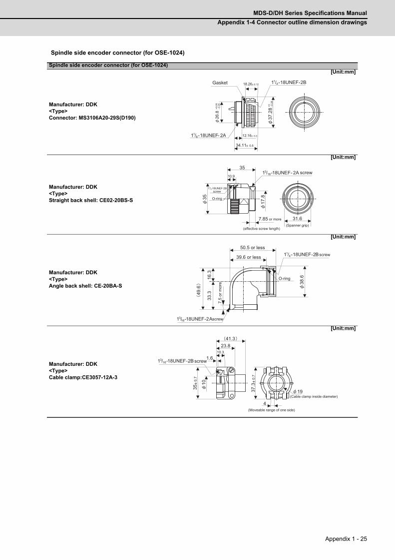
MDS-D/DH Series Specifications Manual
Appendix 1-4 Connector outline dimension drawings
Appendix 1 - 25
Spindle side encoder connector (for OSE-1024)
Spindle side encoder connector (for OSE-1024)
Manufacturer: DDK<Type>Connector: MS3106A20-29S(D190)
[Unit:mm]
Manufacturer: DDK<Type>Straight back shell: CE02-20BS-S
[Unit:mm]
Manufacturer: DDK<Type>Angle back shell: CE-20BA-S
[Unit:mm]
Manufacturer: DDK<Type>Cable clamp:CE3057-12A-3
[Unit:mm]
-0.2
5 +0
.05
26.8
18.26± 0.12
12.16± 0.3 34.11± 0.5
11/8-18UNEF- 2A
11/4-18UNEF-2B
-0.3
8 +0
37
.28
Gasket
13/16- - 2A
17.8
35
35 10.9
11/8-18UNEF-2B
7.85
31.6
18UNEF
(effective screw length)(Spanner grip)
screw
screw
O-ring
or more
38.6
16.3
49.6
33.3
13/16-18UNEF-2A
11/4-18UNEF-2B
O-ring
screw50.5 or less
39.6 or less
7.5
or m
ore
screw
19
4
37.3
±0.
7
23.8 10.3
1.6
10
41.3
35±
0.7
13/16-18UNEF-2B screw
(Moveable range of one side)
(Cable clamp inside diameter)

Appendix 1 Cable and Connector Specifications
MITSUBISHI CNC
Appendix 1 - 26

Appendix 2 - 1
Appendix 2
Restrictions for Lithium Batteries
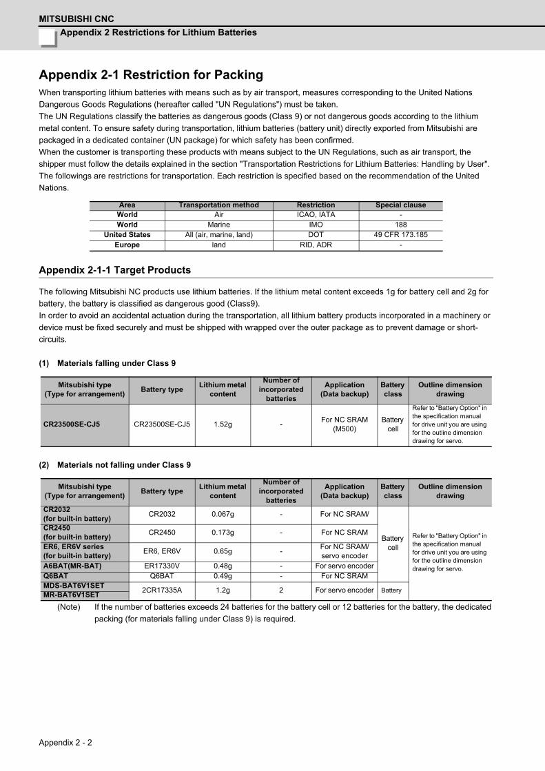
Appendix 2 Restrictions for Lithium Batteries
MITSUBISHI CNC
Appendix 2 - 2
Appendix 2-1 Restriction for PackingWhen transporting lithium batteries with means such as by air transport, measures corresponding to the United Nations
Dangerous Goods Regulations (hereafter called "UN Regulations") must be taken.
The UN Regulations classify the batteries as dangerous goods (Class 9) or not dangerous goods according to the lithium
metal content. To ensure safety during transportation, lithium batteries (battery unit) directly exported from Mitsubishi are
packaged in a dedicated container (UN package) for which safety has been confirmed.
When the customer is transporting these products with means subject to the UN Regulations, such as air transport, the
shipper must follow the details explained in the section "Transportation Restrictions for Lithium Batteries: Handling by User".
The followings are restrictions for transportation. Each restriction is specified based on the recommendation of the United
Nations.
Appendix 2-1-1 Target Products
The following Mitsubishi NC products use lithium batteries. If the lithium metal content exceeds 1g for battery cell and 2g for
battery, the battery is classified as dangerous good (Class9).
In order to avoid an accidental actuation during the transportation, all lithium battery products incorporated in a machinery or
device must be fixed securely and must be shipped with wrapped over the outer package as to prevent damage or short-
circuits.
(1) Materials falling under Class 9
(2) Materials not falling under Class 9
(Note) If the number of batteries exceeds 24 batteries for the battery cell or 12 batteries for the battery, the dedicated
packing (for materials falling under Class 9) is required.
Area Transportation method Restriction Special clauseWorld Air ICAO, IATA -World Marine IMO 188
United States All (air, marine, land) DOT 49 CFR 173.185Europe land RID, ADR -
Mitsubishi type (Type for arrangement)
Battery typeLithium metal
content
Number of incorporated
batteries
Application(Data backup)
Battery class
Outline dimension drawing
CR23500SE-CJ5 CR23500SE-CJ5 1.52g -For NC SRAM
(M500)Battery
cell
Refer to "Battery Option" in the specification manual for drive unit you are using for the outline dimension drawing for servo.
Mitsubishi type (Type for arrangement)
Battery typeLithium metal
content
Number of incorporated
batteries
Application(Data backup)
Battery class
Outline dimension drawing
CR2032 (for built-in battery)
CR2032 0.067g - For NC SRAM/
Battery cell
Refer to "Battery Option" in the specification manual for drive unit you are using for the outline dimension drawing for servo.
CR2450 (for built-in battery)
CR2450 0.173g - For NC SRAM
ER6, ER6V series (for built-in battery)
ER6, ER6V 0.65g -For NC SRAM/ servo encoder
A6BAT(MR-BAT) ER17330V 0.48g - For servo encoderQ6BAT Q6BAT 0.49g - For NC SRAMMDS-BAT6V1SET
2CR17335A 1.2g 2 For servo encoder BatteryMR-BAT6V1SET
MDS-D/DH Series Specifications Manual
Appendix 2-1 Restriction for Packing
Appendix 2 - 3
Appendix 2-1-2 Handling by User
The shipper must confirm the latest IATA Dangerous Goods Regulations, IMDG Codes and laws and orders of the
corresponding export country.
These should be checked by the company commissioned for the actual transportation.
IATA: International Air Transport Association
http://www.iata.org/
IMDG Code: A uniform international code for the transport of dangerous goods by seas determined by IMO (International
Maritime Organization).
http://www.imo.org/
Appendix 2-1-3 Reference
Refer to the following materials for details on the regulations and responses.
Guidelines regarding transportation of lithium batteries and lithium ion batteries
Battery Association of Japan
http://www.baj.or.jp/e/
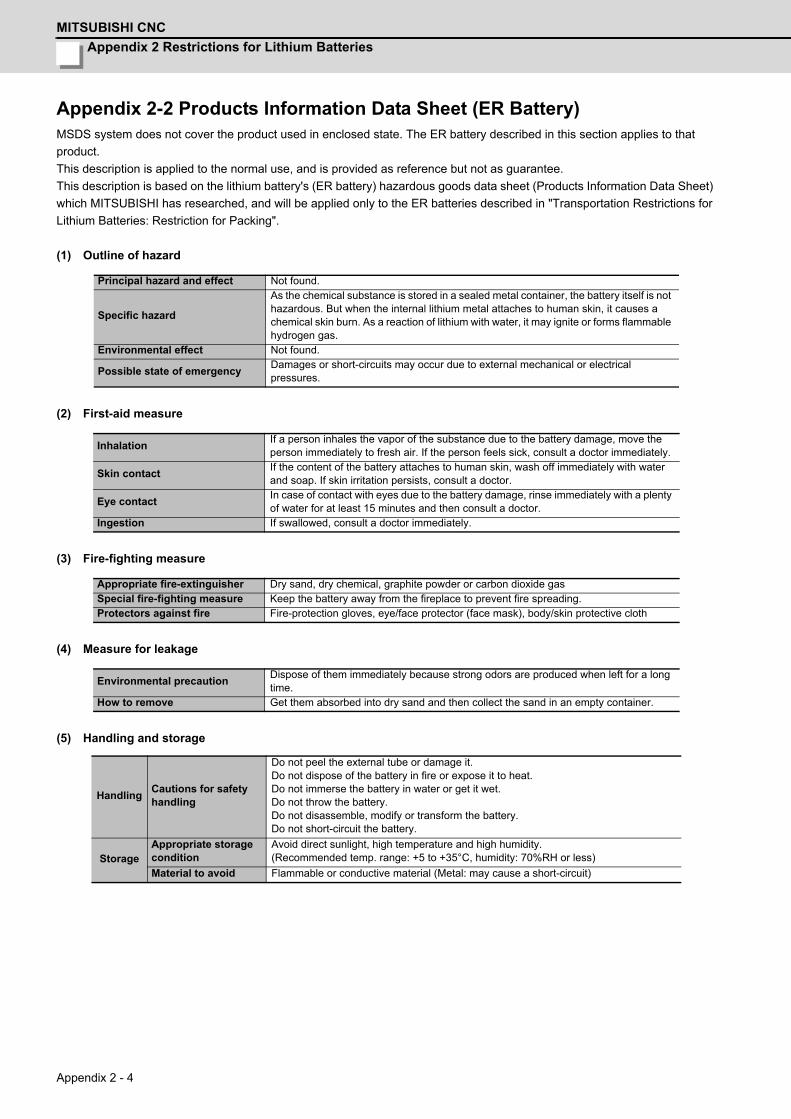
Appendix 2 Restrictions for Lithium Batteries
MITSUBISHI CNC
Appendix 2 - 4
Appendix 2-2 Products Information Data Sheet (ER Battery)MSDS system does not cover the product used in enclosed state. The ER battery described in this section applies to that
product.
This description is applied to the normal use, and is provided as reference but not as guarantee.
This description is based on the lithium battery's (ER battery) hazardous goods data sheet (Products Information Data Sheet)
which MITSUBISHI has researched, and will be applied only to the ER batteries described in "Transportation Restrictions for
Lithium Batteries: Restriction for Packing".
(1) Outline of hazard
(2) First-aid measure
(3) Fire-fighting measure
(4) Measure for leakage
(5) Handling and storage
Principal hazard and effect Not found.
Specific hazard
As the chemical substance is stored in a sealed metal container, the battery itself is not hazardous. But when the internal lithium metal attaches to human skin, it causes a chemical skin burn. As a reaction of lithium with water, it may ignite or forms flammable hydrogen gas.
Environmental effect Not found.
Possible state of emergencyDamages or short-circuits may occur due to external mechanical or electrical pressures.
InhalationIf a person inhales the vapor of the substance due to the battery damage, move the person immediately to fresh air. If the person feels sick, consult a doctor immediately.
Skin contactIf the content of the battery attaches to human skin, wash off immediately with water and soap. If skin irritation persists, consult a doctor.
Eye contactIn case of contact with eyes due to the battery damage, rinse immediately with a plenty of water for at least 15 minutes and then consult a doctor.
Ingestion If swallowed, consult a doctor immediately.
Appropriate fire-extinguisher Dry sand, dry chemical, graphite powder or carbon dioxide gasSpecial fire-fighting measure Keep the battery away from the fireplace to prevent fire spreading. Protectors against fire Fire-protection gloves, eye/face protector (face mask), body/skin protective cloth
Environmental precautionDispose of them immediately because strong odors are produced when left for a long time.
How to remove Get them absorbed into dry sand and then collect the sand in an empty container.
HandlingCautions for safety handling
Do not peel the external tube or damage it. Do not dispose of the battery in fire or expose it to heat. Do not immerse the battery in water or get it wet. Do not throw the battery. Do not disassemble, modify or transform the battery. Do not short-circuit the battery.
StorageAppropriate storage condition
Avoid direct sunlight, high temperature and high humidity. (Recommended temp. range: +5 to +35°C, humidity: 70%RH or less)
Material to avoid Flammable or conductive material (Metal: may cause a short-circuit)
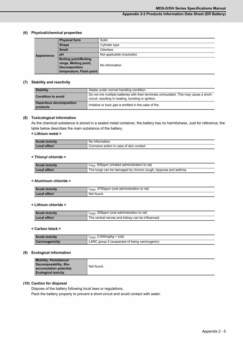
MDS-D/DH Series Specifications Manual
Appendix 2-2 Products Information Data Sheet (ER Battery)
Appendix 2 - 5
(6) Physical/chemical properties
(7) Stability and reactivity
(8) Toxicological information
As the chemical substance is stored in a sealed metal container, the battery has no harmfulness. Just for reference, the
table below describes the main substance of the battery.
< Lithium metal >
< Thionyl chloride >
< Aluminum chloride >
< Lithium chloride >
< Carbon black >
(9) Ecological information
(10) Caution for disposal
Dispose of the battery following local laws or regulations.
Pack the battery properly to prevent a short-circuit and avoid contact with water.
Appearance
Physical form Solid
Shape Cylinder type
Smell Odorless
pH Not applicable (insoluble)
Boiling point/Boiling range, Melting point, Decomposition temperature, Flash point
No information
Stability Stable under normal handling condition.
Condition to avoidDo not mix multiple batteries with their terminals uninsulated. This may cause a short-circuit, resulting in heating, bursting or ignition.
Hazardous decomposition products
Irritative or toxic gas is emitted in the case of fire.
Acute toxicity No information Local effect Corrosive action in case of skin contact
Acute toxicity Lc50: 500ppm (inhaled administration to rat)
Local effect The lungs can be damaged by chronic cough, dyspnea and asthma.
Acute toxicity LD50: 3700ppm (oral administration to rat)
Local effect Not found.
Acute toxicity LD50: 526ppm (oral administration to rat)
Local effect The central nerves and kidney can be influenced.
Acute toxicity LD50: 2,000mg/kg > (rat)
Carcinogenicity LARC group 2 (suspected of being carcinogenic)
Mobility, Persistence/Decomposability, Bio-accumulation potential, Ecological toxicity
Not found.
Appendix 2 Restrictions for Lithium Batteries
MITSUBISHI CNC
Appendix 2 - 6
Appendix 2-3 Forbiddance of Transporting Lithium Battery by Passenger
Aircraft Provided in the Code of Federal RegulationThis regulation became effective from Dec.29, 2004. This law is a domestic law of the United States, however it also applies
to the domestic flight and international flight departing from or arriving in the United States. Therefore, when transporting
lithium batteries to the United State, or within the United State, the shipper must take measures required to transport lithium
batteries. Refer to the Federal Register and the code of Federal Regulation for details.
When transporting primary lithium battery by cargo aircraft, indicate that transportation by passenger aircraft is forbidden on
the exterior box.
"Lithium Metal batteries forbidden for transport aboard Passenger aircraft"
Appendix 2-4 California Code of Regulation "Best Management Practices
for Perchlorate Materials"When any products that contain primary lithium batteries with perchlorate are shipped to or transported through the State of
California, they are subject to the above regulation.The following information must be indicated on the package, etc. of the
products that contain primary lithium batteries (with a perchlorate content of 6 ppb or higher).
"Perchlorate Meterial-special handling may apply. See http://www.dtsc.ca.gov/hazardouswaste/perchlorate"
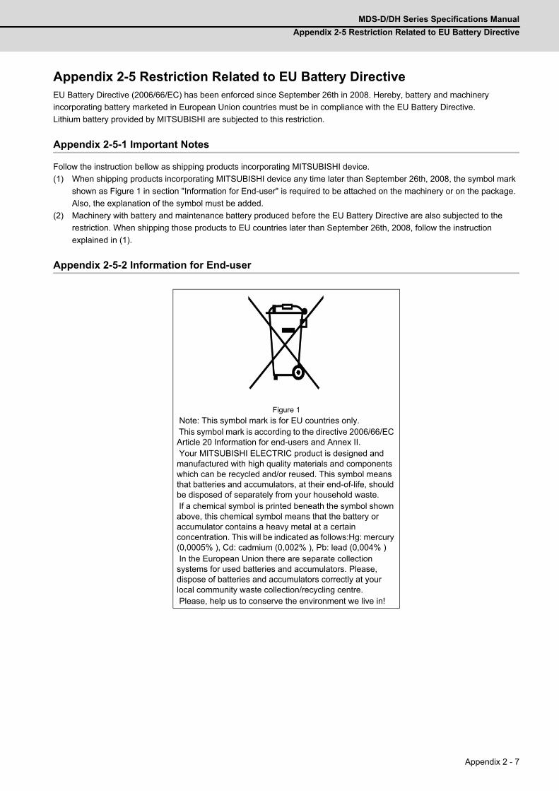
MDS-D/DH Series Specifications Manual
Appendix 2-5 Restriction Related to EU Battery Directive
Appendix 2 - 7
Appendix 2-5 Restriction Related to EU Battery DirectiveEU Battery Directive (2006/66/EC) has been enforced since September 26th in 2008. Hereby, battery and machinery
incorporating battery marketed in European Union countries must be in compliance with the EU Battery Directive.
Lithium battery provided by MITSUBISHI are subjected to this restriction.
Appendix 2-5-1 Important Notes
Follow the instruction bellow as shipping products incorporating MITSUBISHI device.
(1) When shipping products incorporating MITSUBISHI device any time later than September 26th, 2008, the symbol mark
shown as Figure 1 in section "Information for End-user" is required to be attached on the machinery or on the package.
Also, the explanation of the symbol must be added.
(2) Machinery with battery and maintenance battery produced before the EU Battery Directive are also subjected to the
restriction. When shipping those products to EU countries later than September 26th, 2008, follow the instruction
explained in (1).
Appendix 2-5-2 Information for End-user
Figure 1
Note: This symbol mark is for EU countries only. This symbol mark is according to the directive 2006/66/EC Article 20 Information for end-users and Annex II. Your MITSUBISHI ELECTRIC product is designed and manufactured with high quality materials and components which can be recycled and/or reused. This symbol means that batteries and accumulators, at their end-of-life, should be disposed of separately from your household waste. If a chemical symbol is printed beneath the symbol shown above, this chemical symbol means that the battery or accumulator contains a heavy metal at a certain concentration. This will be indicated as follows:Hg: mercury (0,0005% ), Cd: cadmium (0,002% ), Pb: lead (0,004% ) In the European Union there are separate collection systems for used batteries and accumulators. Please, dispose of batteries and accumulators correctly at your local community waste collection/recycling centre. Please, help us to conserve the environment we live in!

Appendix 2 Restrictions for Lithium Batteries
MITSUBISHI CNC
Appendix 2 - 8

Appendix 3 - 1
付録 Ap3 章
Appendix 3 - 1
Appendix 3
EC Declaration of Conformity
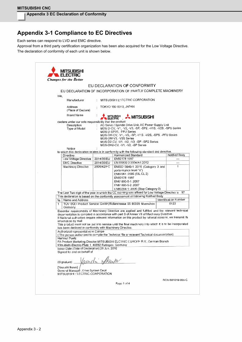
Appendix 3 EC Declaration of Conformity
MITSUBISHI CNC
Appendix 3 - 2
Appendix 3-1 Compliance to EC DirectivesEach series can respond to LVD and EMC directive.
Approval from a third party certification organization has been also acquired for the Low Voltage Directive.
The declaration of conformity of each unit is shown below.

Appendix 4 - 1
付録 Ap4 章
Appendix 4 - 1
Appendix 4
Instruction Manual for Compliance with UL/c-ULStandard
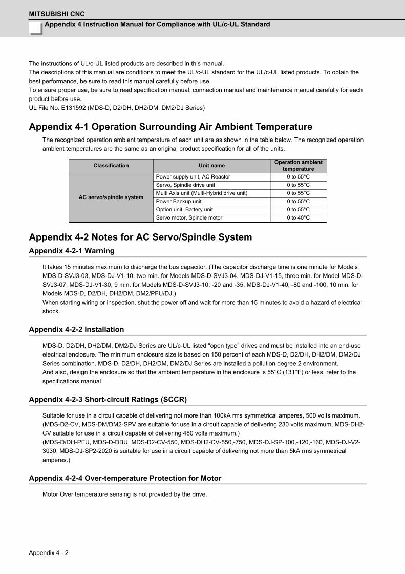
Appendix 4 Instruction Manual for Compliance with UL/c-UL Standard
MITSUBISHI CNC
Appendix 4 - 2
The instructions of UL/c-UL listed products are described in this manual.
The descriptions of this manual are conditions to meet the UL/c-UL standard for the UL/c-UL listed products. To obtain the
best performance, be sure to read this manual carefully before use.
To ensure proper use, be sure to read specification manual, connection manual and maintenance manual carefully for each
product before use.
UL File No. E131592 (MDS-D, D2/DH, DH2/DM, DM2/DJ Series)
Appendix 4-1 Operation Surrounding Air Ambient TemperatureThe recognized operation ambient temperature of each unit are as shown in the table below. The recognized operation
ambient temperatures are the same as an original product specification for all of the units.
Appendix 4-2 Notes for AC Servo/Spindle SystemAppendix 4-2-1 Warning
It takes 15 minutes maximum to discharge the bus capacitor. (The capacitor discharge time is one minute for Models
MDS-D-SVJ3-03, MDS-DJ-V1-10; two min. for Models MDS-D-SVJ3-04, MDS-DJ-V1-15, three min. for Model MDS-D-
SVJ3-07, MDS-DJ-V1-30, 9 min. for Models MDS-D-SVJ3-10, -20 and -35, MDS-DJ-V1-40, -80 and -100, 10 min. for
Models MDS-D, D2/DH, DH2/DM, DM2/PFU/DJ.)
When starting wiring or inspection, shut the power off and wait for more than 15 minutes to avoid a hazard of electrical
shock.
Appendix 4-2-2 Installation
MDS-D, D2/DH, DH2/DM, DM2/DJ Series are UL/c-UL listed "open type" drives and must be installed into an end-use
electrical enclosure. The minimum enclosure size is based on 150 percent of each MDS-D, D2/DH, DH2/DM, DM2/DJ
Series combination. MDS-D, D2/DH, DH2/DM, DM2/DJ Series are installed a pollution degree 2 environment.
And also, design the enclosure so that the ambient temperature in the enclosure is 55°C (131°F) or less, refer to the
specifications manual.
Appendix 4-2-3 Short-circuit Ratings (SCCR)
Suitable for use in a circuit capable of delivering not more than 100kA rms symmetrical amperes, 500 volts maximum.
(MDS-D2-CV, MDS-DM/DM2-SPV are suitable for use in a circuit capable of delivering 230 volts maximum, MDS-DH2-
CV suitable for use in a circuit capable of delivering 480 volts maximum.)
(MDS-D/DH-PFU, MDS-D-DBU, MDS-D2-CV-550, MDS-DH2-CV-550,-750, MDS-DJ-SP-100,-120,-160, MDS-DJ-V2-
3030, MDS-DJ-SP2-2020 is suitable for use in a circuit capable of delivering not more than 5kA rms symmetrical
amperes.)
Appendix 4-2-4 Over-temperature Protection for Motor
Motor Over temperature sensing is not provided by the drive.
Classification Unit nameOperation ambient
temperature
AC servo/spindle system
Power supply unit, AC Reactor 0 to 55°C
Servo, Spindle drive unit 0 to 55°C
Multi Axis unit (Multi-Hybrid drive unit) 0 to 55°C
Power Backup unit 0 to 55°C
Option unit, Battery unit 0 to 55°C
Servo motor, Spindle motor 0 to 40°C
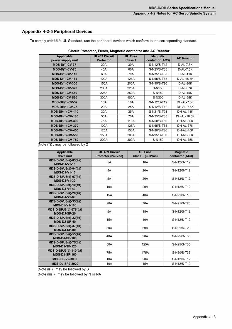
MDS-D/DH Series Specifications Manual
Appendix 4-2 Notes for AC Servo/Spindle System
Appendix 4 - 3
Appendix 4-2-5 Peripheral Devices
To comply with UL/c-UL Standard, use the peripheral devices which conform to the corresponding standard.
Circuit Protector, Fuses, Magnetic contactor and AC Reactor
(Note (*)) : may be followed by 2
(Note (#)) : may be followed by S
(Note (##)) : may be followed by N or NA
Applicable power supply unit
UL489 Circuit Protector
UL FuseClass T
Magnetic contactor (AC3)
AC Reactor
MDS-D(*)-CV-37 20A 30A S-N12/S-T12 D-AL-7.5K
MDS-D(*)-CV-75 40A 60A S-N25/S-T35 D-AL-7.5K
MDS-D(*)-CV-110 60A 70A S-N35/S-T35 D-AL-11K
MDS-D(*)-CV-185 100A 125A S-N65/S-T65 D-AL-18.5K
MDS-D(*)-CV-300 150A 200A S-N95/S-T80 D-AL-30K
MDS-D(*)-CV-370 200A 225A S-N150 D-AL-37K
MDS-D(*)-CV-450 225A 250A S-N150 D-AL-45K
MDS-D(*)-CV-550 300A 400A S-N300 D-AL-55K
MDS-DH(*)-CV-37 10A 10A S-N12/S-T12 DH-AL-7.5K
MDS-DH(*)-CV-75 20A 25A S-N12/S-T12 DH-AL-7.5K
MDS-DH(*)-CV-110 30A 35A S-N21/S-T21 DH-AL-11K
MDS-DH(*)-CV-185 50A 70A S-N25/S-T35 DH-AL-18.5K
MDS-DH(*)-CV-300 75A 110A S-N50/S-T50 DH-AL-30K
MDS-DH(*)-CV-370 100A 125A S-N65/S-T65 DH-AL-37K
MDS-DH(*)-CV-450 125A 150A S-N80/S-T80 DH-AL-45K
MDS-DH(*)-CV-550 150A 200A S-N95/S-T80 DH-AL-55K
MDS-DH(*)-CV-750 200A 300A S-N150 DH-AL-75K
Applicable drive unit
UL 489 Circuit Protector (240Vac)
UL FuseClass T (300Vac)
Magnetic contactor (AC3)
MDS-D-SVJ3(#)-03(##)MDS-DJ-V1-10
5A 10A S-N12/S-T12
MDS-D-SVJ3(#)-04(##)MDS-DJ-V1-15
5A 20A S-N12/S-T12
MDS-D-SVJ3(#)-07(##)MDS-DJ-V1-30
5A 20A S-N12/S-T12
MDS-D-SVJ3(#)-10(##)MDS-DJ-V1-40
10A 20A S-N12/S-T12
MDS-D-SVJ3(#)-20(##)MDS-DJ-V1-80
15A 40A S-N21/S-T18
MDS-D-SVJ3(#)-35(##)MDS-DJ-V1-100
20A 70A S-N21/S-T20
MDS-D-SPJ3(#)-075(##)MDS-DJ-SP-20
5A 15A S-N12/S-T12
MDS-D-SPJ3(#)-22(##)MDS-DJ-SP-40
15A 40A S-N12/S-T12
MDS-D-SPJ3(#)-37(##)MDS-DJ-SP-80
30A 60A S-N21/S-T20
MDS-D-SPJ3(#)-55(##)MDS-DJ-SP-100
40A 90A S-N25/S-T35
MDS-D-SPJ3(#)-75(##)MDS-DJ-SP-120
50A 125A S-N25/S-T35
MDS-D-SPJ3(#)-110(##)MDS-DJ-SP-160
75A 175A S-N50/S-T35
MDS-DJ-V2-3030 10A 20A S-N12/S-T12
MDS-DJ-SP2-2020 10A 15A S-N12/S-T12
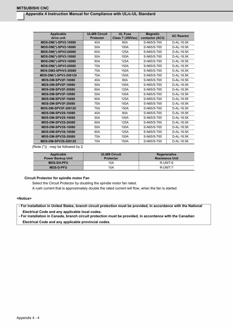
Appendix 4 Instruction Manual for Compliance with UL/c-UL Standard
MITSUBISHI CNC
Appendix 4 - 4
(Note (*)) : may be followed by 2
Circuit Protector for spindle motor Fan
Select the Circuit Protector by doubling the spindle motor fan rated.
A rush current that is approximately double the rated current will flow, when the fan is started.
<Notice>
Applicable drive unit
UL489 Circuit Protector
UL FuseClass T (300Vac)
Magnetic contactor (AC3)
AC Reactor
MDS-DM(*)-SPV2-10080 40A 80A S-N65/S-T65 D-AL-18.5K
MDS-DM(*)-SPV2-16080 50A 100A S-N65/S-T65 D-AL-18.5K
MDS-DM(*)-SPV2-20080 60A 125A S-N65/S-T65 D-AL-18.5K
MDS-DM(*)-SPV3-10080 50A 100A S-N65/S-T65 D-AL-18.5K
MDS-DM(*)-SPV3-16080 60A 125A S-N65/S-T65 D-AL-18.5K
MDS-DM(*)-SPV3-20080 75A 150A S-N65/S-T65 D-AL-18.5K
MDS-DM2-SPHV3-20080 75A 150A S-N65/S-T65 D-AL-18.5K
MDS-DM(*)-SPV3-200120 75A 150A S-N65/S-T65 D-AL-18.5K
MDS-DM-SPV2F-10080 40A 80A S-N65/S-T65 D-AL-18.5K
MDS-DM-SPV2F-16080 50A 100A S-N65/S-T65 D-AL-18.5K
MDS-DM-SPV2F-20080 60A 125A S-N65/S-T65 D-AL-18.5K
MDS-DM-SPV3F-10080 50A 100A S-N65/S-T65 D-AL-18.5K
MDS-DM-SPV3F-16080 60A 125A S-N65/S-T65 D-AL-18.5K
MDS-DM-SPV3F-20080 75A 150A S-N65/S-T65 D-AL-18.5K
MDS-DM-SPV3F-200120 75A 150A S-N65/S-T65 D-AL-18.5K
MDS-DM-SPV2S-10080 40A 80A S-N65/S-T65 D-AL-18.5K
MDS-DM-SPV2S-16080 50A 100A S-N65/S-T65 D-AL-18.5K
MDS-DM-SPV2S-20080 60A 125A S-N65/S-T65 D-AL-18.5K
MDS-DM-SPV3S-10080 50A 100A S-N65/S-T65 D-AL-18.5K
MDS-DM-SPV3S-16080 60A 125A S-N65/S-T65 D-AL-18.5K
MDS-DM-SPV3S-20080 75A 150A S-N65/S-T65 D-AL-18.5K
MDS-DM-SPV3S-200120 75A 150A S-N65/S-T65 D-AL-18.5K
ApplicablePower Backup Unit
UL489 Circuit Protector
RegenerativeResistance Unit
MDS-DH-PFU 10A R-UNIT-6
MDS-D-PFU 10A R-UNIT-7
- For installation in United States, branch circuit protection must be provided, in accordance with the National
Electrical Code and any applicable local codes.- For installation in Canada, branch circuit protection must be provided, in accordance with the Canadian
Electrical Code and any applicable provincial codes.
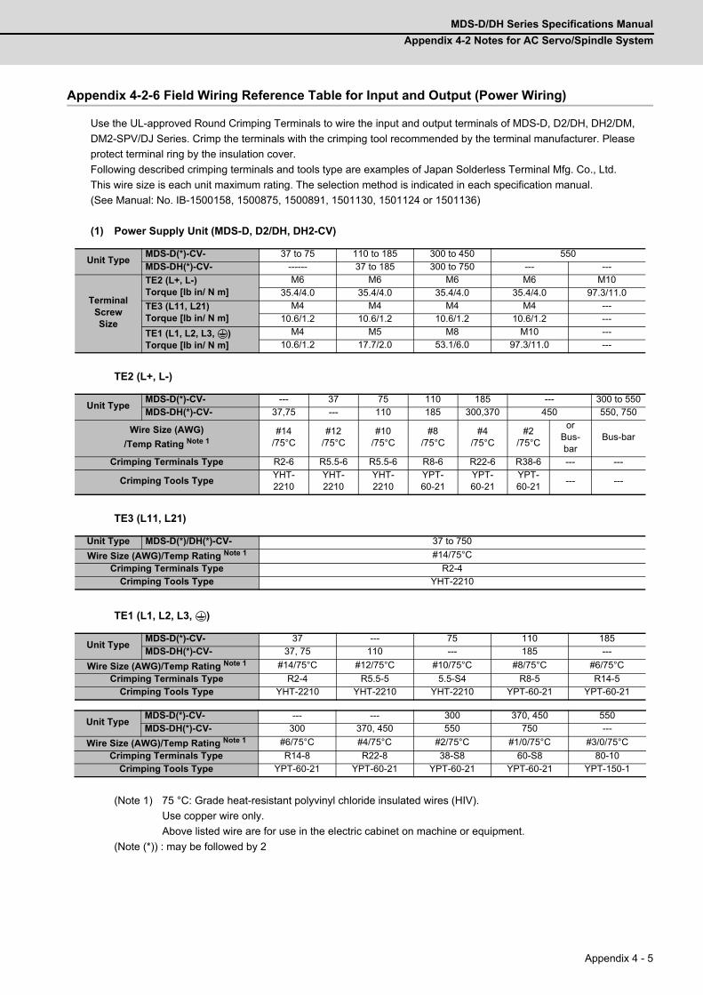
MDS-D/DH Series Specifications Manual
Appendix 4-2 Notes for AC Servo/Spindle System
Appendix 4 - 5
Appendix 4-2-6 Field Wiring Reference Table for Input and Output (Power Wiring)
Use the UL-approved Round Crimping Terminals to wire the input and output terminals of MDS-D, D2/DH, DH2/DM,
DM2-SPV/DJ Series. Crimp the terminals with the crimping tool recommended by the terminal manufacturer. Please
protect terminal ring by the insulation cover.
Following described crimping terminals and tools type are examples of Japan Solderless Terminal Mfg. Co., Ltd.
This wire size is each unit maximum rating. The selection method is indicated in each specification manual.
(See Manual: No. IB-1500158, 1500875, 1500891, 1501130, 1501124 or 1501136)
(1) Power Supply Unit (MDS-D, D2/DH, DH2-CV)
TE2 (L+, L-)
TE3 (L11, L21)
TE1 (L1, L2, L3, )
(Note 1) 75 °C: Grade heat-resistant polyvinyl chloride insulated wires (HIV).
Use copper wire only.
Above listed wire are for use in the electric cabinet on machine or equipment.
(Note (*)) : may be followed by 2
Unit TypeMDS-D(*)-CV- 37 to 75 110 to 185 300 to 450 550MDS-DH(*)-CV- ------ 37 to 185 300 to 750 --- ---
Terminal Screw Size
TE2 (L+, L-)Torque [lb in/ N m]
M6 M6 M6 M6 M1035.4/4.0 35.4/4.0 35.4/4.0 35.4/4.0 97.3/11.0
TE3 (L11, L21)Torque [lb in/ N m]
M4 M4 M4 M4 ---10.6/1.2 10.6/1.2 10.6/1.2 10.6/1.2 ---
TE1 (L1, L2, L3, )Torque [lb in/ N m]
M4 M5 M8 M10 ---10.6/1.2 17.7/2.0 53.1/6.0 97.3/11.0 ---
Unit TypeMDS-D(*)-CV- --- 37 75 110 185 --- 300 to 550MDS-DH(*)-CV- 37,75 --- 110 185 300,370 450 550, 750
Wire Size (AWG)
/Temp Rating Note 1#14
/75°C#12
/75°C#10
/75°C#8
/75°C#4
/75°C#2
/75°C
or Bus-bar
Bus-bar
Crimping Terminals Type R2-6 R5.5-6 R5.5-6 R8-6 R22-6 R38-6 --- ---
Crimping Tools TypeYHT-2210
YHT-2210
YHT-2210
YPT-60-21
YPT-60-21
YPT-60-21
--- ---
Unit Type MDS-D(*)/DH(*)-CV- 37 to 750
Wire Size (AWG)/Temp Rating Note 1 #14/75°C
Crimping Terminals Type R2-4Crimping Tools Type YHT-2210
Unit TypeMDS-D(*)-CV- 37 --- 75 110 185MDS-DH(*)-CV- 37, 75 110 --- 185 ---
Wire Size (AWG)/Temp Rating Note 1 #14/75°C #12/75°C #10/75°C #8/75°C #6/75°C
Crimping Terminals Type R2-4 R5.5-5 5.5-S4 R8-5 R14-5Crimping Tools Type YHT-2210 YHT-2210 YHT-2210 YPT-60-21 YPT-60-21
Unit TypeMDS-D(*)-CV- --- --- 300 370, 450 550MDS-DH(*)-CV- 300 370, 450 550 750 ---
Wire Size (AWG)/Temp Rating Note 1 #6/75°C #4/75°C #2/75°C #1/0/75°C #3/0/75°C
Crimping Terminals Type R14-8 R22-8 38-S8 60-S8 80-10Crimping Tools Type YPT-60-21 YPT-60-21 YPT-60-21 YPT-60-21 YPT-150-1
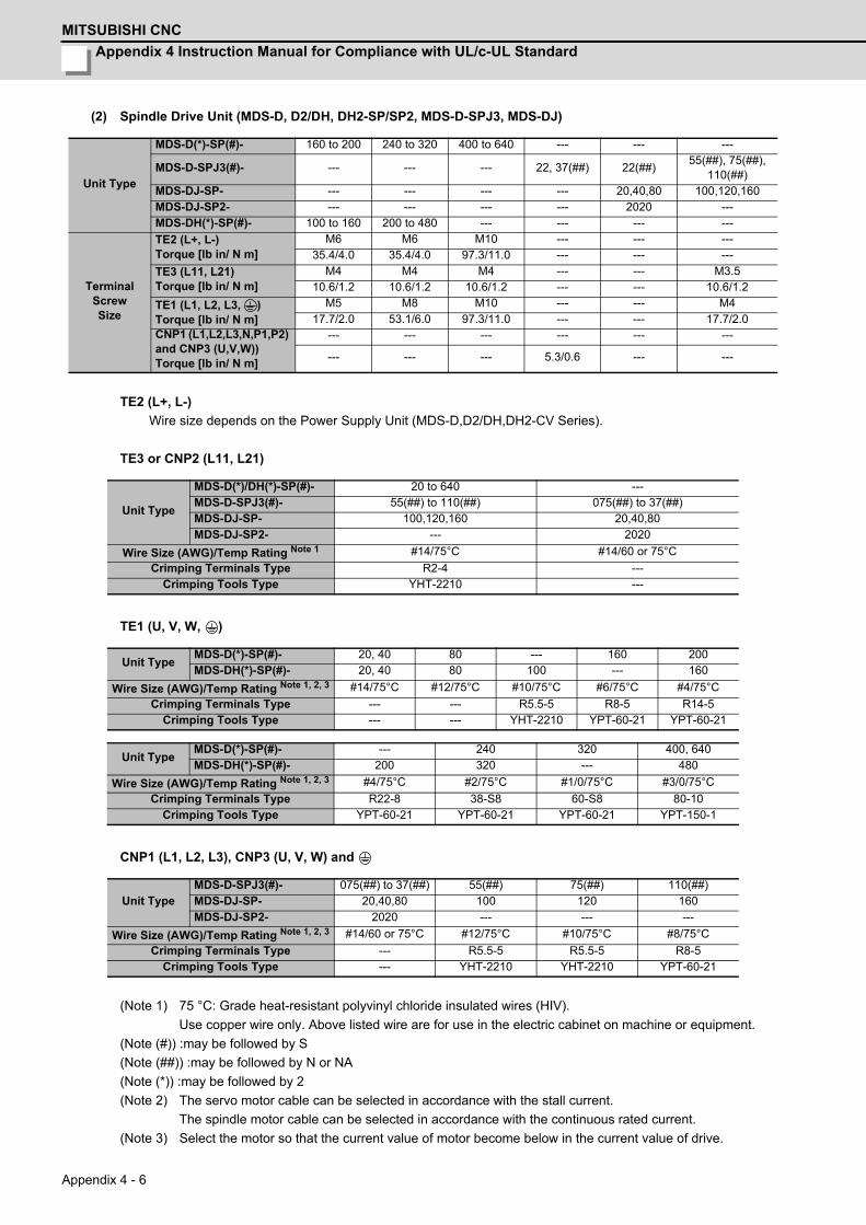
Appendix 4 Instruction Manual for Compliance with UL/c-UL Standard
MITSUBISHI CNC
Appendix 4 - 6
(2) Spindle Drive Unit (MDS-D, D2/DH, DH2-SP/SP2, MDS-D-SPJ3, MDS-DJ)
TE2 (L+, L-)
Wire size depends on the Power Supply Unit (MDS-D,D2/DH,DH2-CV Series).
TE3 or CNP2 (L11, L21)
TE1 (U, V, W, )
CNP1 (L1, L2, L3), CNP3 (U, V, W) and
(Note 1) 75 °C: Grade heat-resistant polyvinyl chloride insulated wires (HIV).
Use copper wire only. Above listed wire are for use in the electric cabinet on machine or equipment.
(Note (#)) :may be followed by S
(Note (##)) :may be followed by N or NA
(Note (*)) :may be followed by 2
(Note 2) The servo motor cable can be selected in accordance with the stall current.
The spindle motor cable can be selected in accordance with the continuous rated current.
(Note 3) Select the motor so that the current value of motor become below in the current value of drive.
Unit Type
MDS-D(*)-SP(#)- 160 to 200 240 to 320 400 to 640 --- --- ---
MDS-D-SPJ3(#)- --- --- --- 22, 37(##) 22(##)55(##), 75(##),
110(##)MDS-DJ-SP- --- --- --- --- 20,40,80 100,120,160MDS-DJ-SP2- --- --- --- --- 2020 ---MDS-DH(*)-SP(#)- 100 to 160 200 to 480 --- --- --- ---
Terminal Screw Size
TE2 (L+, L-)Torque [lb in/ N m]
M6 M6 M10 --- --- ---35.4/4.0 35.4/4.0 97.3/11.0 --- --- ---
TE3 (L11, L21)Torque [lb in/ N m]
M4 M4 M4 --- --- M3.510.6/1.2 10.6/1.2 10.6/1.2 --- --- 10.6/1.2
TE1 (L1, L2, L3, )Torque [lb in/ N m]
M5 M8 M10 --- --- M417.7/2.0 53.1/6.0 97.3/11.0 --- --- 17.7/2.0
CNP1 (L1,L2,L3,N,P1,P2) and CNP3 (U,V,W))Torque [lb in/ N m]
--- --- --- --- --- ---
--- --- --- 5.3/0.6 --- ---
Unit Type
MDS-D(*)/DH(*)-SP(#)- 20 to 640 ---MDS-D-SPJ3(#)- 55(##) to 110(##) 075(##) to 37(##)MDS-DJ-SP- 100,120,160 20,40,80MDS-DJ-SP2- --- 2020
Wire Size (AWG)/Temp Rating Note 1 #14/75°C #14/60 or 75°C
Crimping Terminals Type R2-4 ---Crimping Tools Type YHT-2210 ---
Unit TypeMDS-D(*)-SP(#)- 20, 40 80 --- 160 200MDS-DH(*)-SP(#)- 20, 40 80 100 --- 160
Wire Size (AWG)/Temp Rating Note 1, 2, 3 #14/75°C #12/75°C #10/75°C #6/75°C #4/75°C
Crimping Terminals Type --- --- R5.5-5 R8-5 R14-5Crimping Tools Type --- --- YHT-2210 YPT-60-21 YPT-60-21
Unit TypeMDS-D(*)-SP(#)- --- 240 320 400, 640MDS-DH(*)-SP(#)- 200 320 --- 480
Wire Size (AWG)/Temp Rating Note 1, 2, 3 #4/75°C #2/75°C #1/0/75°C #3/0/75°C
Crimping Terminals Type R22-8 38-S8 60-S8 80-10Crimping Tools Type YPT-60-21 YPT-60-21 YPT-60-21 YPT-150-1
Unit TypeMDS-D-SPJ3(#)- 075(##) to 37(##) 55(##) 75(##) 110(##)MDS-DJ-SP- 20,40,80 100 120 160MDS-DJ-SP2- 2020 --- --- ---
Wire Size (AWG)/Temp Rating Note 1, 2, 3 #14/60 or 75°C #12/75°C #10/75°C #8/75°C
Crimping Terminals Type --- R5.5-5 R5.5-5 R8-5Crimping Tools Type --- YHT-2210 YHT-2210 YPT-60-21
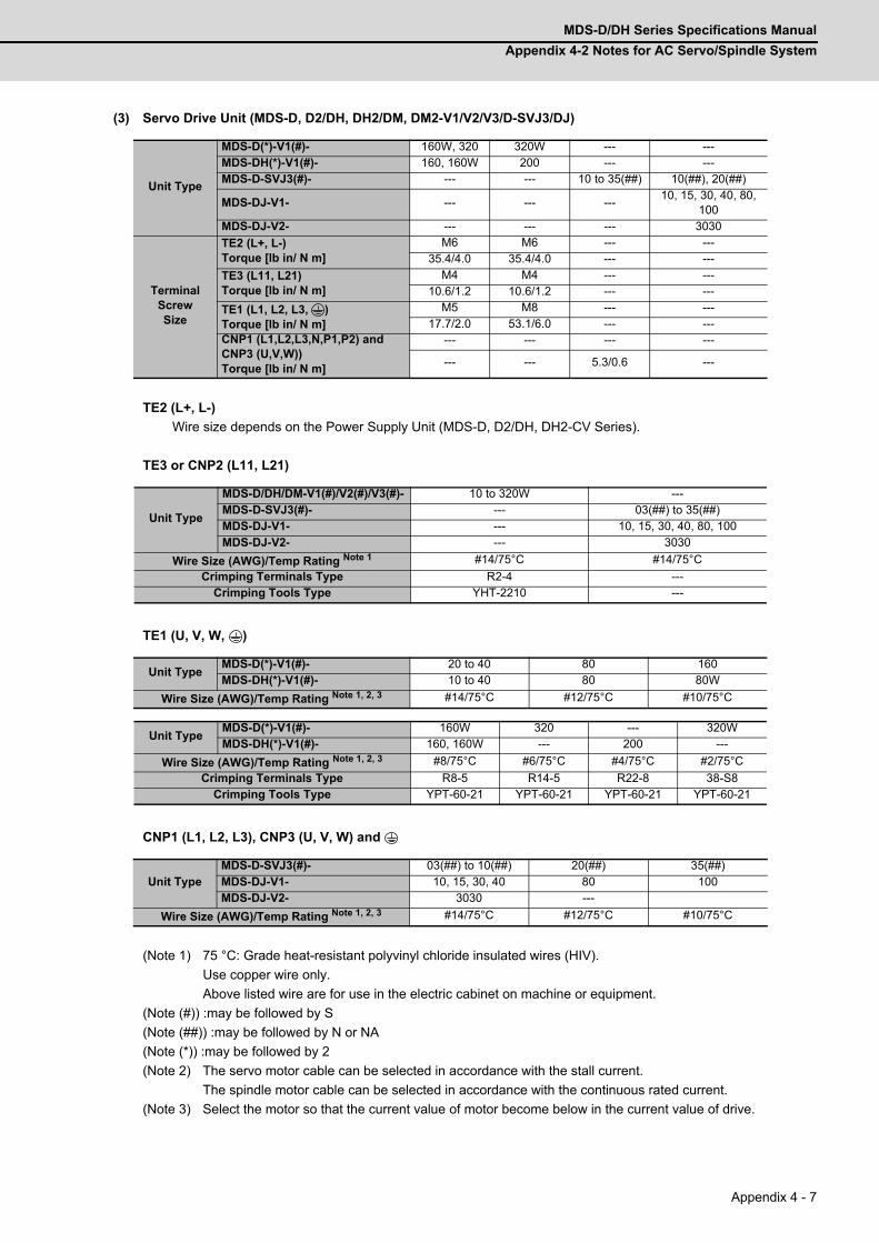
MDS-D/DH Series Specifications Manual
Appendix 4-2 Notes for AC Servo/Spindle System
Appendix 4 - 7
(3) Servo Drive Unit (MDS-D, D2/DH, DH2/DM, DM2-V1/V2/V3/D-SVJ3/DJ)
TE2 (L+, L-)
Wire size depends on the Power Supply Unit (MDS-D, D2/DH, DH2-CV Series).
TE3 or CNP2 (L11, L21)
TE1 (U, V, W, )
CNP1 (L1, L2, L3), CNP3 (U, V, W) and
(Note 1) 75 °C: Grade heat-resistant polyvinyl chloride insulated wires (HIV).
Use copper wire only.
Above listed wire are for use in the electric cabinet on machine or equipment.
(Note (#)) :may be followed by S
(Note (##)) :may be followed by N or NA
(Note (*)) :may be followed by 2
(Note 2) The servo motor cable can be selected in accordance with the stall current.
The spindle motor cable can be selected in accordance with the continuous rated current.
(Note 3) Select the motor so that the current value of motor become below in the current value of drive.
Unit Type
MDS-D(*)-V1(#)- 160W, 320 320W --- ---MDS-DH(*)-V1(#)- 160, 160W 200 --- ---MDS-D-SVJ3(#)- --- --- 10 to 35(##) 10(##), 20(##)
MDS-DJ-V1- --- --- ---10, 15, 30, 40, 80,
100MDS-DJ-V2- --- --- --- 3030
Terminal Screw Size
TE2 (L+, L-)Torque [lb in/ N m]
M6 M6 --- ---35.4/4.0 35.4/4.0 --- ---
TE3 (L11, L21)Torque [lb in/ N m]
M4 M4 --- ---10.6/1.2 10.6/1.2 --- ---
TE1 (L1, L2, L3, )Torque [lb in/ N m]
M5 M8 --- ---17.7/2.0 53.1/6.0 --- ---
CNP1 (L1,L2,L3,N,P1,P2) and CNP3 (U,V,W))Torque [lb in/ N m]
--- --- --- ---
--- --- 5.3/0.6 ---
Unit Type
MDS-D/DH/DM-V1(#)/V2(#)/V3(#)- 10 to 320W ---MDS-D-SVJ3(#)- --- 03(##) to 35(##)MDS-DJ-V1- --- 10, 15, 30, 40, 80, 100MDS-DJ-V2- --- 3030
Wire Size (AWG)/Temp Rating Note 1 #14/75°C #14/75°C
Crimping Terminals Type R2-4 ---Crimping Tools Type YHT-2210 ---
Unit TypeMDS-D(*)-V1(#)- 20 to 40 80 160MDS-DH(*)-V1(#)- 10 to 40 80 80W
Wire Size (AWG)/Temp Rating Note 1, 2, 3 #14/75°C #12/75°C #10/75°C
Unit TypeMDS-D(*)-V1(#)- 160W 320 --- 320WMDS-DH(*)-V1(#)- 160, 160W --- 200 ---
Wire Size (AWG)/Temp Rating Note 1, 2, 3 #8/75°C #6/75°C #4/75°C #2/75°C
Crimping Terminals Type R8-5 R14-5 R22-8 38-S8Crimping Tools Type YPT-60-21 YPT-60-21 YPT-60-21 YPT-60-21
Unit TypeMDS-D-SVJ3(#)- 03(##) to 10(##) 20(##) 35(##)MDS-DJ-V1- 10, 15, 30, 40 80 100MDS-DJ-V2- 3030 ---
Wire Size (AWG)/Temp Rating Note 1, 2, 3 #14/75°C #12/75°C #10/75°C

Appendix 4 Instruction Manual for Compliance with UL/c-UL Standard
MITSUBISHI CNC
Appendix 4 - 8
(4) Option Unit : Dynamic Brake Unit (MDS-D-DBU)
TE1 (U, V, W, )
(Note 1) 75 °C: Grade heat-resistant polyvinyl chloride insulated wires (HIV).
Use copper wire only. Above listed wire are for use in the electric cabinet on machine or equipment.
(5) AC Reactor (D/DH-AL)
Input/Output (L11, L12, L13, L21, L22, L23)
The wire connected with AC Reactor becomes same size as TE1 of the selected Power supply unit.
(6) Multi Axis Unit (Multi-Hybrid drive unit) (MDS-DM, DM2-SPV)
TE1 (L1, L2, L3) and
TE1 (U, V, W) and
Type MDS-D-DBU
Terminal ScrewSize
U, V, W, M4
Torque [lb in/ N m] 10.6/1.2
Unit Type MDS-D-DBU
Wire Size (AWG) /Temp Rating Note 1 #10/75°C
Crimping Terminals Type R5.5-4
Crimping Tools Type YHT-2210
TypeD-AL- 7.5K, 11K 18.5K to 45K 55KDH-AL- 7.5K, 11K 18.5K to 75K ---
Terminal Screw Size
L11, L12, L13, L21, L22, L23 M5 M6 M10
Torque [lb in/ N m] 17.7/2.0 35.4/4.0 97.3/11.0
Unit TypeMDS-DM(*)-SPV2(###) -10080 -16080 -20080 ---MDS-DM(*)-SPV3(###) -10080 -16080 -20080 -200120MDS-DM2-SPHV3 --- --- -20080 ---
TerminalScrewSize
TE1 (L1,L2,L3,U,V,W)Torque [lb in/ N m]
M5 M5 M5 M517.7 / 2.0 17.7 / 2.0 17.7 / 2.0 17.7 / 2.0
CN31L/M/S (U,V,W)Torque [lb in/ N m]
--- --- --- ------ --- --- ---
PE ( )Torque [lb in/ N m]
M5 M5 M5 M517.7 / 2.0 17.7 / 2.0 17.7 / 2.0 17.7 / 2.0
Unit TypeMDS-DM(*)-SPV2(###) -10080 -16080 -20080 ---MDS-DM(*)-SPV3(###) -10080 -16080 -20080 -200120MDS-DM2-SPHV3 --- --- -20080 ---
Wire Size (AWG) /Temp Rating Note 1 #4/75°C #4/75°C #4/75°C #4/75°C
Crimping Terminals Type R22-S5 R22-S5 R22-S5 R22-S5Crimping Tools Type YPT-60-21 YPT-60-21 YPT-60-21 YPT-60-21
Unit Type
MDS-DM(*)-SPV2(###) -10080 -16080 --- -20080
MDS-DM(*)-SPV3(###) -10080 -16080 ----20080
-200120MDS-DM2-SPHV3 --- --- -20080 ---
Wire Size (AWG) /Temp Rating Note 1, 2, 3 #10/75°C #8/75°C #6/75°C #4/75°C
Crimping Terminals Type Note 2 R5.5-5 R8-5 R14-5 R22-5
Crimping Tools Type YHT-2210 YPT-60-21 YPT-60-21 YPT-60-21
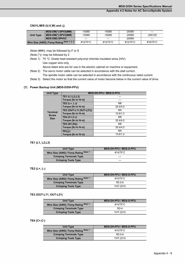
MDS-D/DH Series Specifications Manual
Appendix 4-2 Notes for AC Servo/Spindle System
Appendix 4 - 9
CN31L/M/S (U,V,W) and
(Note (###)) :may be followed by F or S
(Note (*)) :may be followed by 2
(Note 1) 75 °C: Grade heat-resistant polyvinyl chloride insulated wires (HIV).
Use copper wire only.
Above listed wire are for use in the electric cabinet on machine or equipment.
(Note 2) The servo motor cable can be selected in accordance with the stall current.
The spindle motor cable can be selected in accordance with the continuous rated current.
(Note 3) Select the motor so that the current value of motor become below in the current value of drive.
(7) Power Backup Unit (MDS-D/DH-PFU)
TE1 (L1, L2,L3)
TE2 (L+, L-)
TE3 (OUT-L11, OUT-L21)
TE4 (C+,C-)
Unit TypeMDS-DM(*)-SPV2(###) -10080 -16080 -20080 ---MDS-DM(*)-SPV3(###) -10080 -16080 -20080 -200120MDS-DM2-SPHV3 --- --- -20080 ---
Wire Size (AWG) /Temp Rating Note 1, 2, 3 #12/75°C #12/75°C #12/75°C #10/75°C
Unit Type MDS-DH-PFU / MDS-D-PFU
TerminalScrewSize
TE1 (L1,L2,L3)Torque [lb in/ N m]
------
TE2 (L+, L-))Torque [lb in/ N m]
M635.4/4.0
TE3 (OUT-L11,OUT-L21))Torque [lb in/ N m]
M410.6/1.2
TE4 (C+,C-))Torque [lb in/ N m]
M635.4/4.0
TE5 (R1,R2))Torque [lb in/ N m]
M635.4/4.0
PE( )Torque [lb in/ N m]
M410.6/1.2
Unit Type MDS-DH-PFU / MDS-D-PFU
Wire Size (AWG) /Temp Rating Note 1 #14/75°C
Crimping Terminals Type ---
Crimping Tools Type ---
Unit Type MDS-DH-PFU / MDS-D-PFU
Wire Size (AWG) /Temp Rating Note 1 #10/75°C
Crimping Terminals Type R5.5-6
Crimping Tools Type YHT-2210
Unit Type MDS-DH-PFU / MDS-D-PFU
Wire Size (AWG) /Temp Rating Note 1 #14/75°C
Crimping Terminals Type R2-4
Crimping Tools Type YHT-2210
Unit Type MDS-DH-PFU / MDS-D-PFU
Wire Size (AWG) /Temp Rating Note 1 #10/75°C
Crimping Terminals Type R5.5-6
Crimping Tools Type YHT-2210

Appendix 4 Instruction Manual for Compliance with UL/c-UL Standard
MITSUBISHI CNC
Appendix 4 - 10
TE5 (R1,R2)
PE ( )
Option Unit : R-Unit (R-UNIT-6 / R-UNIT-7)
TE1 (R1,R2)
PE ( )
Option Unit : Capacitor Unit (MDS-D-CU / MDS-DH-CU)
TE1 (C+, C-)
TE2 (C+, C-)
Unit Type MDS-DH-PFU / MDS-D-PFU
Wire Size (AWG) /Temp Rating Note 1 #10/75°C
Crimping Terminals Type R5.5-6
Crimping Tools Type YHT-2210
Unit Type MDS-DH-PFU / MDS-D-PFU
Wire Size (AWG) /Temp Rating Note 1 #14/75°C
Crimping Terminals Type R2-4
Crimping Tools Type YHT-2210
Unit Type R-UNIT-6 / R-UNIT-7
TerminalScrewSize
TE1 (R1, R2)Torque [lb in/ N m]
M410.6/1.2
PE( )Torque [lb in/ N m]
M410.6/1.2
Unit Type R-UNIT-6 / R-UNIT-7
Wire Size (AWG) /Temp Rating Note 1 #10/75°C
Crimping Terminals Type R5.5-4
Crimping Tools Type YHT-2210
Unit Type R-UNIT-6 / R-UNIT-7
Wire Size (AWG) /Temp Rating Note 1 #10/75°C
Crimping Terminals Type R5.5-4
Crimping Tools Type YHT-2210
Unit Type MDS-D-CU / MDS-DH-CU
TerminalScrewSize
TE1 (C+, C-)Torque [lb in/ N m]
M1097.3/11.0
TE2 (C+, C-)Torque [lb in/ N m]
M635.4/4.0
PE( )Torque [lb in/ N m]
M1097.3/11.0
Unit Type MDS-D-CU / MDS-DH-CU
Wire Size (AWG) /Temp Rating Note 1 #10/75°C
Crimping Terminals Type R5.5-10
Crimping Tools Type YHT-2210
Unit Type MDS-D-CU / MDS-DH-CU
Wire Size (AWG) /Temp Rating Note 1 #10/75°C or more
Crimping Terminals Type R5.5-6
Crimping Tools Type YHT-2210
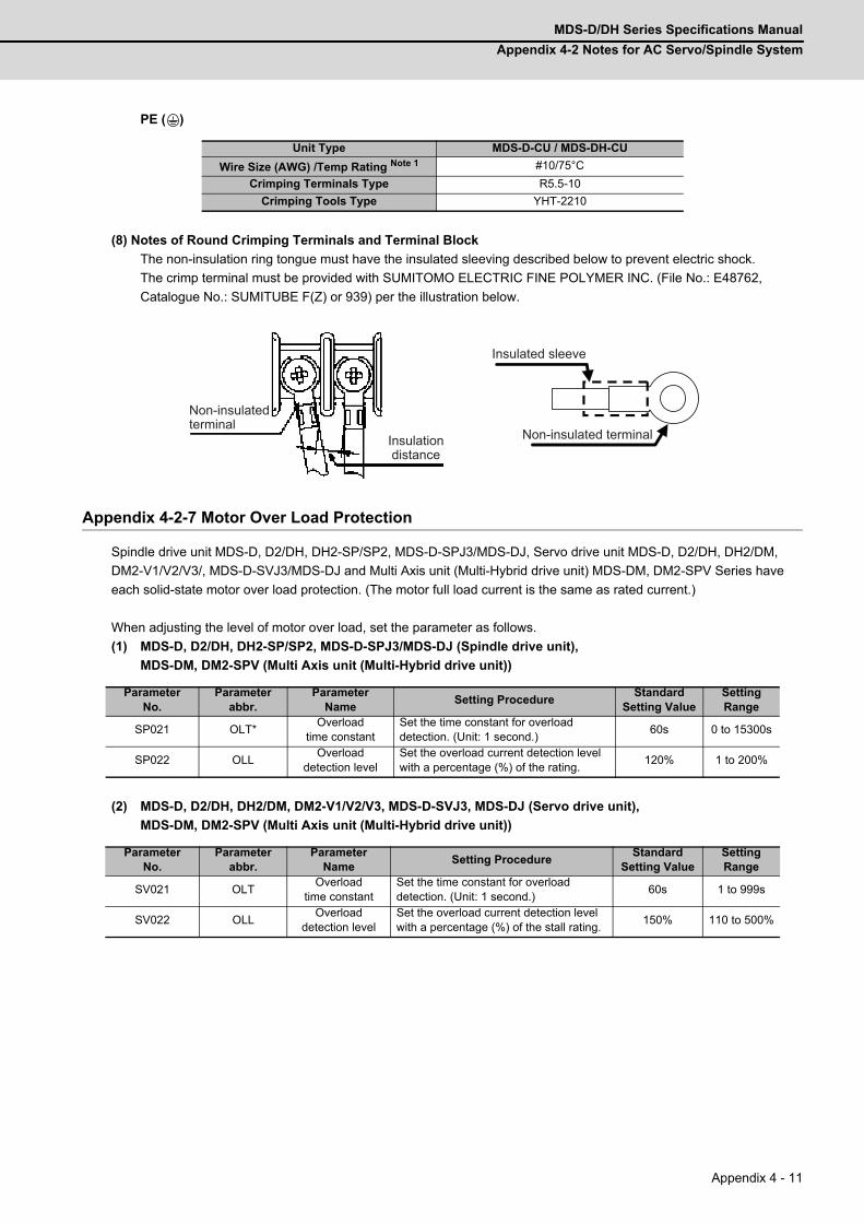
MDS-D/DH Series Specifications Manual
Appendix 4-2 Notes for AC Servo/Spindle System
Appendix 4 - 11
PE ( )
(8) Notes of Round Crimping Terminals and Terminal Block
The non-insulation ring tongue must have the insulated sleeving described below to prevent electric shock.
The crimp terminal must be provided with SUMITOMO ELECTRIC FINE POLYMER INC. (File No.: E48762,
Catalogue No.: SUMITUBE F(Z) or 939) per the illustration below.
Appendix 4-2-7 Motor Over Load Protection
Spindle drive unit MDS-D, D2/DH, DH2-SP/SP2, MDS-D-SPJ3/MDS-DJ, Servo drive unit MDS-D, D2/DH, DH2/DM,
DM2-V1/V2/V3/, MDS-D-SVJ3/MDS-DJ and Multi Axis unit (Multi-Hybrid drive unit) MDS-DM, DM2-SPV Series have
each solid-state motor over load protection. (The motor full load current is the same as rated current.)
When adjusting the level of motor over load, set the parameter as follows.
(1) MDS-D, D2/DH, DH2-SP/SP2, MDS-D-SPJ3/MDS-DJ (Spindle drive unit),
MDS-DM, DM2-SPV (Multi Axis unit (Multi-Hybrid drive unit))
(2) MDS-D, D2/DH, DH2/DM, DM2-V1/V2/V3, MDS-D-SVJ3, MDS-DJ (Servo drive unit),
MDS-DM, DM2-SPV (Multi Axis unit (Multi-Hybrid drive unit))
Unit Type MDS-D-CU / MDS-DH-CU
Wire Size (AWG) /Temp Rating Note 1 #10/75°C
Crimping Terminals Type R5.5-10
Crimping Tools Type YHT-2210
ParameterNo.
Parameterabbr.
ParameterName
Setting ProcedureStandard
Setting ValueSettingRange
SP021 OLT*Overload
time constantSet the time constant for overload detection. (Unit: 1 second.)
60s 0 to 15300s
SP022 OLLOverload
detection levelSet the overload current detection level with a percentage (%) of the rating.
120% 1 to 200%
ParameterNo.
Parameterabbr.
ParameterName
Setting ProcedureStandard
Setting ValueSettingRange
SV021 OLTOverload
time constantSet the time constant for overload detection. (Unit: 1 second.)
60s 1 to 999s
SV022 OLLOverload
detection levelSet the overload current detection level with a percentage (%) of the stall rating.
150% 110 to 500%
Insulated sleeve
Non-insulated terminalInsulation distance
Non-insulated terminal

Appendix 4 Instruction Manual for Compliance with UL/c-UL Standard
MITSUBISHI CNC
Appendix 4 - 12
Appendix 4-2-8 Flange of Servo Motor
Mount the servo motor on a flange which has the following size or produces an equivalent or higher heat dissipation
effect:
Appendix 4-2-9 Spindle Drive/Motor Combinations
Following combinations are the Standard combinations.
Flange size(mm)
Servo MotorHF, HF-H, HP, HP-H, HF-KP, HF-MP, HF-SP
150×150×6 50 to 100W
250×250×6 200 to 400W
250×250×12 0.5 to 1.5kW
300×300×20 2.0 to 7.0kW
800×800×35 9.0 to 11.0kW
Drive UnitRating Output (kW) of Applicable Spindle Motor
SJ, SJ-V/VL Series Note 1
MDS-D(*)-SP(#)-20 0.75
MDS-D(*)-SP(#)-40 0.75, 1.5, 2.2
MDS-D(*)-SP(#)-80 2.2, 3.7, 7.5
MDS-D(*)-SP(#)-160 7.5, 11
MDS-D(*)-SP(#)-200 11, 15, 18.5
MDS-D(*)-SP(#)-240 18.5, 22
MDS-D(*)-SP(#)-320 22, 26, 30
MDS-D(*)-SP(#)-400 30, 37, 45
MDS-D(*)-SP(#)-640 37, 45, 55
MDS-D(*)-SP2(#)-2020 0.75, 1.5 / 0.75, 1.5
MDS-D(*)-SP2(#)-8040 2.2, 3.7, 7.5 / 0.75, 1.5, 2.2
MDS-D(*)-SP2(#)-8080 2.2, 3.7, 7.5 / 2.2, 3.7, 7.5
MDS-D(*)-SP2(#)-16080 7.5, 11 / 2.2, 3.7, 7.5
Drive UnitRating Output (kW) of Applicable Spindle Motor
SJ-4, SJ-4-V/VL Series Note 1
MDS-DH(*)-SP(#)-20 0.75, 1.5, 2.2, 3.7
MDS-DH(*)-SP(#)-40 2.2, 3.7, 5.5, 7.5
MDS-DH(*)-SP(#)-80 2.2, 3.7, 7.5, 11
MDS-DH(*)-SP(#)-100 7.5, 11, 15, 18.5
MDS-DH(*)-SP(#)-160 18.5, 22, 26, 30
MDS-DH(*)-SP(#)-200 26, 30, 37, 45
MDS-DH(*)-SP(#)-320 30, 37, 45, 55
MDS-DH(*)-SP(#)-480 45, 55, 60
MDS-DH(*)-SP2(#)-2020 0.75, 1.5, 2.2, 3.7 / 0.75, 1.5, 2.2, 3.7
MDS-DH(*)-SP2(#)-4040 2.2, 3.7, 5.5, 7.5 / 2.2, 3.7, 5.5, 7.5
MDS-DH(*)-SP2(#)-8040 2.2, 3.7, 7.5, 11 / 2.2, 3.7, 5.5, 7.5
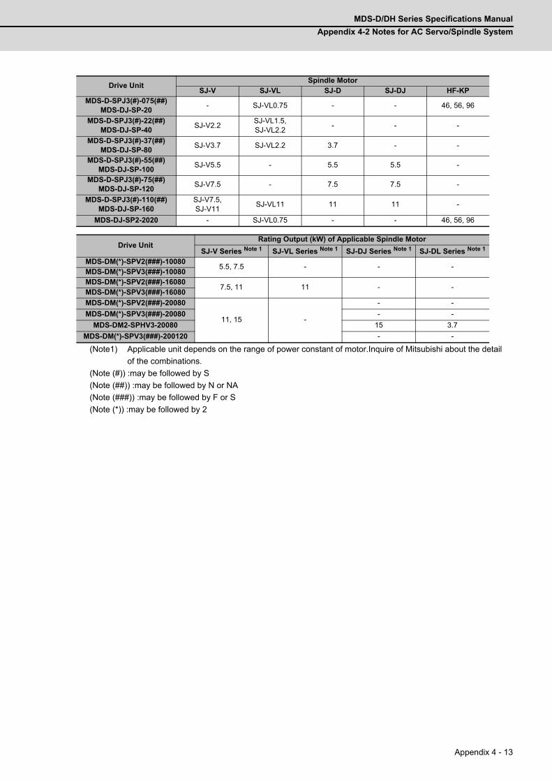
MDS-D/DH Series Specifications Manual
Appendix 4-2 Notes for AC Servo/Spindle System
Appendix 4 - 13
(Note1) Applicable unit depends on the range of power constant of motor.Inquire of Mitsubishi about the detail
of the combinations.
(Note (#)) :may be followed by S
(Note (##)) :may be followed by N or NA
(Note (###)) :may be followed by F or S
(Note (*)) :may be followed by 2
Drive UnitSpindle Motor
SJ-V SJ-VL SJ-D SJ-DJ HF-KPMDS-D-SPJ3(#)-075(##)
MDS-DJ-SP-20- SJ-VL0.75 - - 46, 56, 96
MDS-D-SPJ3(#)-22(##)MDS-DJ-SP-40
SJ-V2.2SJ-VL1.5, SJ-VL2.2
- - -
MDS-D-SPJ3(#)-37(##)MDS-DJ-SP-80
SJ-V3.7 SJ-VL2.2 3.7 - -
MDS-D-SPJ3(#)-55(##)MDS-DJ-SP-100
SJ-V5.5 - 5.5 5.5 -
MDS-D-SPJ3(#)-75(##)MDS-DJ-SP-120
SJ-V7.5 - 7.5 7.5 -
MDS-D-SPJ3(#)-110(##)MDS-DJ-SP-160
SJ-V7.5, SJ-V11
SJ-VL11 11 11 -
MDS-DJ-SP2-2020 - SJ-VL0.75 - - 46, 56, 96
Drive UnitRating Output (kW) of Applicable Spindle Motor
SJ-V Series Note 1 SJ-VL Series Note 1 SJ-DJ Series Note 1 SJ-DL Series Note 1
MDS-DM(*)-SPV2(###)-100805.5, 7.5 - - -
MDS-DM(*)-SPV3(###)-10080MDS-DM(*)-SPV2(###)-16080
7.5, 11 11 - -MDS-DM(*)-SPV3(###)-16080
MDS-DM(*)-SPV2(###)-20080
11, 15 -
- -
MDS-DM(*)-SPV3(###)-20080 - -
MDS-DM2-SPHV3-20080 15 3.7
MDS-DM(*)-SPV3(###)-200120 - -
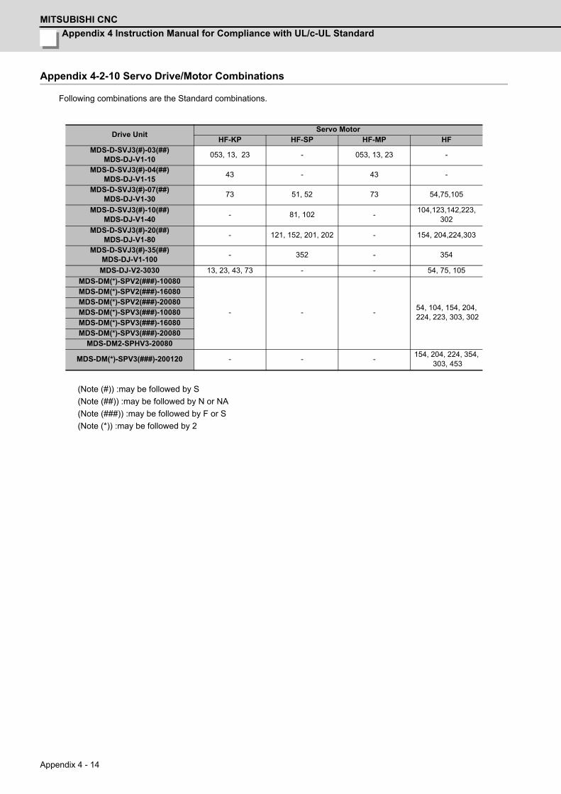
Appendix 4 Instruction Manual for Compliance with UL/c-UL Standard
MITSUBISHI CNC
Appendix 4 - 14
Appendix 4-2-10 Servo Drive/Motor Combinations
Following combinations are the Standard combinations.
(Note (#)) :may be followed by S
(Note (##)) :may be followed by N or NA
(Note (###)) :may be followed by F or S
(Note (*)) :may be followed by 2
Drive UnitServo Motor
HF-KP HF-SP HF-MP HFMDS-D-SVJ3(#)-03(##)
MDS-DJ-V1-10053, 13, 23 - 053, 13, 23 -
MDS-D-SVJ3(#)-04(##)MDS-DJ-V1-15
43 - 43 -
MDS-D-SVJ3(#)-07(##)MDS-DJ-V1-30
73 51, 52 73 54,75,105
MDS-D-SVJ3(#)-10(##)MDS-DJ-V1-40
- 81, 102 -104,123,142,223,
302
MDS-D-SVJ3(#)-20(##)MDS-DJ-V1-80
- 121, 152, 201, 202 - 154, 204,224,303
MDS-D-SVJ3(#)-35(##)MDS-DJ-V1-100
- 352 - 354
MDS-DJ-V2-3030 13, 23, 43, 73 - - 54, 75, 105
MDS-DM(*)-SPV2(###)-10080
- - -54, 104, 154, 204, 224, 223, 303, 302
MDS-DM(*)-SPV2(###)-16080MDS-DM(*)-SPV2(###)-20080MDS-DM(*)-SPV3(###)-10080MDS-DM(*)-SPV3(###)-16080MDS-DM(*)-SPV3(###)-20080
MDS-DM2-SPHV3-20080
MDS-DM(*)-SPV3(###)-200120 - - -154, 204, 224, 354,
303, 453

MDS-D/DH Series Specifications Manual
Appendix 4-3 AC Servo/Spindle System Connection
Appendix 4 - 15
Appendix 4-3 AC Servo/Spindle System ConnectionAppendix 4-3-1 MDS-D, D2/DH, DH2/DM, DM2-Vx/SP Series
CN1B CN1A
CN4 CN9
CN3L CN2L
CN3M
CN23A
CN2M
CN1B CN1A
CN4 CN9
L+/L- L11/L21
CN4
CB
MU/MV/MW
L1/L2/L3 U/V/W LU/LV/LW
CN9
MC
CB
CN3L CN2L
CN3M CN2M
CN3SCN2S
SU/SV/SW
CN23B
MDS-D,D2/DH.DH2/DM.DM2-V1/V2/V3 MDS-D,D2/DH,DH2-SP
MDS-D,D2/DH,DH2-CV
(CN24) (CN23)
(MCCB)
Series Series Series
Refer to specification manual
Battery Unit
Note: It recommends installing.
Contactor Fuse
or Circuit Protector
Servo Motor Spindle Motor
Encoder FAN
Servo Motor
AC Reactor
Encoder and Thermal Protection
From NC
External Emergency Stop
Regarding the connection of NC, see the CNC manual book.
Enclosure Side
Machine Side
Servo Motor
Encoder Encoder
D/DH/DM : IB-1500875 or IB-1500891D2/DH2/DM2 : IB-1501124 or IB-1501136 3 phase
DH,DH2 Series: 380 to 480VACD,D2/DM,DM2 Series: 200 to 230VAC
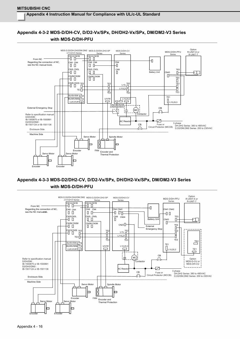
Appendix 4 Instruction Manual for Compliance with UL/c-UL Standard
MITSUBISHI CNC
Appendix 4 - 16
Appendix 4-3-2 MDS-D/DH-CV, D/D2-Vx/SPx, DH/DH2-Vx/SPx, DM/DM2-V3 Series
with MDS-D/DH-PFU
Appendix 4-3-3 MDS-D2/DH2-CV, D/D2-Vx/SPx, DH/DH2-Vx/SPx, DM/DM2-V3 Series
with MDS-D/DH-PFU
CN1B CN1A
CN4 CN9
CN3L CN2L
CN3M
CN23A
CN2M
CN1B CN1A
CN4CN9
L+/L-
L11/L21
CN4
MU/MV/MW L1/L2/L3 U/V/W LU/LV/LW
CN9
MC
CN3L CN2L
CN3M CN2M
CN23B
CN3SCN2S
SU/SV/SW
TE2
TE3
TE2
TE3
TE2
TE3 TE3
TE2
TE1
TE5 CN43
TE4
L1/L2/L3
CB
MDS-D,D2/DH,DH2-SP MDS-D/DH-CV
CB
MDS-D/DH-PFU
(CN24) (CN23)
From NC
External Emergency Stop
Regarding the connection of NC, see the NC manual book.
Machine Side Servo Motor Spindle Motor
Encoder FAN Servo Motor
Encoder
Battery Unit
Contactor
AC Reactor
Encoder and Thermal Protection
Encoder
Servo Motor
MDS-D,D2/DH,DH2/DM.DM2-V1/V2/V3 Series Series Series
Fuse or Circuit Protector (MCCB)
3 phase DH,DH2 Series: 380 to 480VAC D,D2/DM,DM2 Series: 200 to 230VACEnclosure Side
Refer to specification manual D/DH/DM : IB-1500875 or IB-1500891D2/DH2/DM2 : IB-1501124 or IB-1501136
Series
OptionR-UNIT-6 or
R-UNIT-7
TE3
TE2
TE5 CN43
TE4
L1/L2/L3
CN41 CN42
MC CB
TE1
TE2
CN1B CN1A
CN4 CN9
CN3L CN2L
CN3M CN2M
CN1B CN1A
CN4 CN9
L+/L-
L11/L21
CN4
MU/MV/MW L1/L2/L3 U/V/W LU/LV/LW
CN9 CN3L CN2L
CN3M CN2M
CN3S CN2S
SU/SV/SW
TE2
TE3
TE2
TE3
TE2
TE3
CN41
CN23
CN24
MDS-D,D2/DH,DH2-SP MDS-D2/DH2-CV MDS-D/DH-PFU
From NC
External Emergency Stop
Regarding the connection of NC, see the NC manual book.
Enclosure Side
Machine Side Servo Motor Spindle Motor
Encoder FAN Servo Motor
Encoder
Battery Unit
CB
Contactor
AC Reactor
Encoder and Thermal Protection
Encoder
TE1
Servo Motor
Fuse or Circuit Protector (MCCB)
3 phase DH,DH2 Series: 380 to 480VAC D,D2/DM,DM2 Series: 200 to 230VAC
Refer to specification manual D/DH/DM : IB-1500875 or IB-1500891D2/DH2/DM2 : IB-1501124 or IB-1501136
MDS-D,D2/DH,DH2/DM.DM2-V1/V2/V3 Series Series Series Series
OptionR-UNIT-6 or
R-UNIT-7
OptionMDS-D-CU orMDS-DH-CU
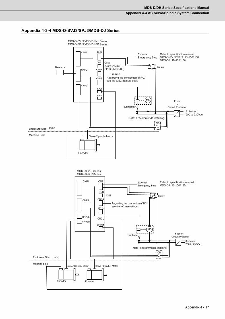
MDS-D/DH Series Specifications Manual
Appendix 4-3 AC Servo/Spindle System Connection
Appendix 4 - 17
Appendix 4-3-4 MDS-D-SVJ3/SPJ3/MDS-DJ Series
CN1B
CN1A
CN2
CNP2
CN9CNP1
CNP3
MC
CB
CN3
CN8
MDS-D-SVJ3/MDS-DJ-V1MDS-D-SPJ3/MDS-DJ-SP
From NC
External Emergency Stop
Enclosure Side
Machine Side Servo/Spindle Motor
Encoder
Contactor
Note: It recommends installing.
Input
Resistor
3 phases200 to 230Vac
CN8(Only SVJ3S, SPJ3S,MDS-DJ)
Fuse or
Circuit Protector
Regarding the connection of NC, see the CNC manual book.
Refer to specification manual MDS-D-SVJ3/SPJ3 : IB-1500158MDS-DJ : IB-1501130
SeriesSeries
Relay
MDS-DJ-V2MDS-DJ-SP2
CN1B
CN1A
CN2CNP3L
2M
CNP2
CNP1 CN9
CN8CN8
MC
CB
L
External Emergency Stop
Regarding the connection of NC, see the NC manual book.
Enclosure Side
Machine Side Servo / Spindle Motor
Encoder
Contactor Fuse or Circuit Protector
3 phases200 to 230Vac
Note : It recommends installing.
Relay
Input
CN
CNP3M
Servo / Spindle Motor
Encoder
SeriesSeries
Refer to specification manual MDS-DJ : IB-1501130

Appendix 4 Instruction Manual for Compliance with UL/c-UL Standard
MITSUBISHI CNC
Appendix 4 - 18
Appendix 4-3-5 MDS-DM, DM2-SPV Series
MC
CB
CN22
CN9B CN9A
CN2L
OPT1
CN2SP
CN31M CN31L
CN3SP
L1/L2/L3
CN2M
CN2S
CN3L
CN3M
CN3S
U/V/W CN31S
MDS-DM,DM2-SPV Series
Encoder FAN Encoder Encoder
From NC
External Emergency Stop
Regarding the connection of NC, see the NC manual book.
Refer to specification manual
Enclosure Side
Machine Side Servo Motor Spindle Motor Servo Motor
Fuse or Circuit Protector
3 phase 200 to 230VAC Input
AC Reactor
Contactor
Servo Motor
Note : It recommends installing.
Relay
24V stabilized Power supply
Encoder and Thermal Protection
IB-1500891, IB-1501136
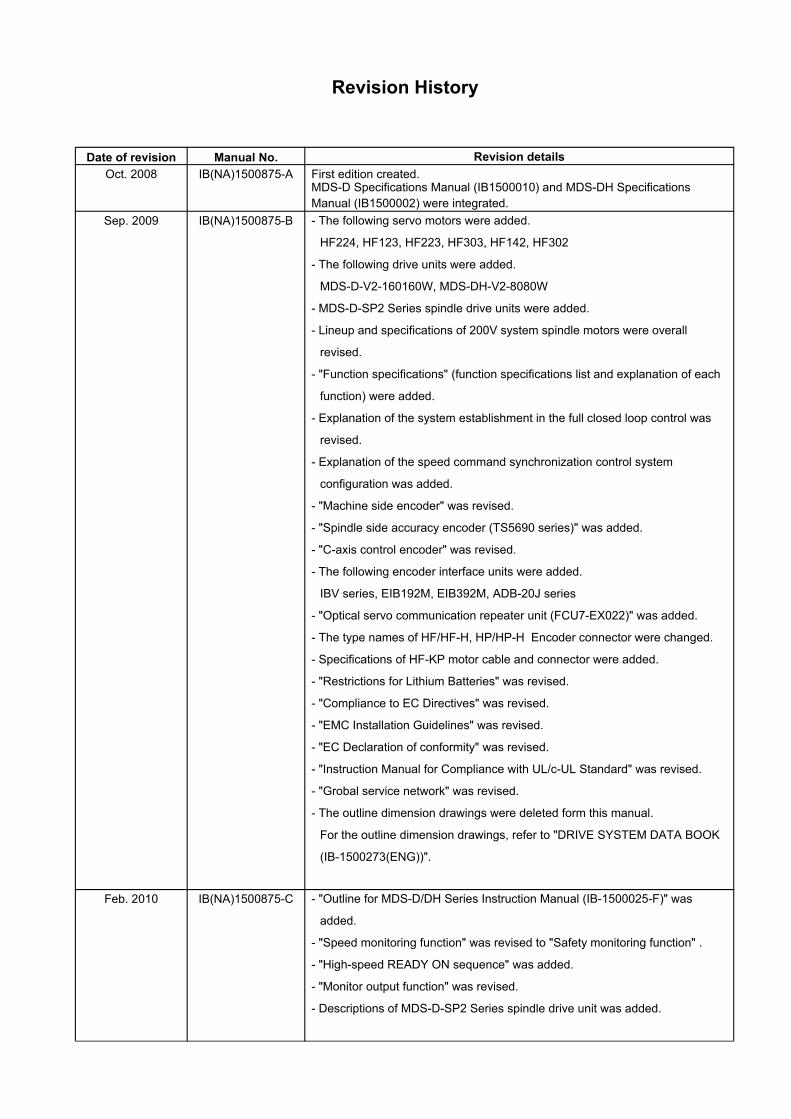
Revision History
Date of revision Manual No. Revision details
Oct. 2008 IB(NA)1500875-A First edition created.MDS-D Specifications Manual (IB1500010) and MDS-DH Specifications Manual (IB1500002) were integrated.
Sep. 2009 IB(NA)1500875-B - The following servo motors were added.
HF224, HF123, HF223, HF303, HF142, HF302
- The following drive units were added.
MDS-D-V2-160160W, MDS-DH-V2-8080W
- MDS-D-SP2 Series spindle drive units were added.
- Lineup and specifications of 200V system spindle motors were overall
revised.
- "Function specifications" (function specifications list and explanation of each
function) were added.
- Explanation of the system establishment in the full closed loop control was
revised.
- Explanation of the speed command synchronization control system
configuration was added.
- "Machine side encoder" was revised.
- "Spindle side accuracy encoder (TS5690 series)" was added.
- "C-axis control encoder" was revised.
- The following encoder interface units were added.
IBV series, EIB192M, EIB392M, ADB-20J series
- "Optical servo communication repeater unit (FCU7-EX022)" was added.
- The type names of HF/HF-H, HP/HP-H Encoder connector were changed.
- Specifications of HF-KP motor cable and connector were added.
- "Restrictions for Lithium Batteries" was revised.
- "Compliance to EC Directives" was revised.
- "EMC Installation Guidelines" was revised.
- "EC Declaration of conformity" was revised.
- "Instruction Manual for Compliance with UL/c-UL Standard" was revised.
- "Grobal service network" was revised.
- The outline dimension drawings were deleted form this manual.
For the outline dimension drawings, refer to "DRIVE SYSTEM DATA BOOK
(IB-1500273(ENG))".
Feb. 2010 IB(NA)1500875-C - "Outline for MDS-D/DH Series Instruction Manual (IB-1500025-F)" was
added.
- "Speed monitoring function" was revised to "Safety monitoring function" .
- "High-speed READY ON sequence" was added.
- "Monitor output function" was revised.
- Descriptions of MDS-D-SP2 Series spindle drive unit was added.
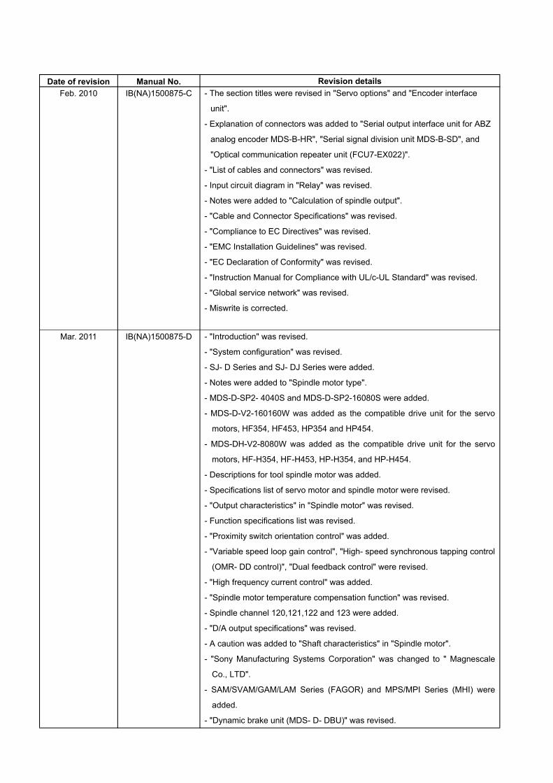
Date of revision Manual No. Revision details
Feb. 2010 IB(NA)1500875-C - The section titles were revised in "Servo options" and "Encoder interface
unit".
- Explanation of connectors was added to "Serial output interface unit for ABZ
analog encoder MDS-B-HR", "Serial signal division unit MDS-B-SD", and
"Optical communication repeater unit (FCU7-EX022)".
- "List of cables and connectors" was revised.
- Input circuit diagram in "Relay" was revised.
- Notes were added to "Calculation of spindle output".
- "Cable and Connector Specifications" was revised.
- "Compliance to EC Directives" was revised.
- "EMC Installation Guidelines" was revised.
- "EC Declaration of Conformity" was revised.
- "Instruction Manual for Compliance with UL/c-UL Standard" was revised.
- "Global service network" was revised.
- Miswrite is corrected.
Mar. 2011 IB(NA)1500875-D - "Introduction" was revised.
- "System configuration" was revised.
- SJ- D Series and SJ- DJ Series were added.
- Notes were added to "Spindle motor type".
- MDS-D-SP2- 4040S and MDS-D-SP2-16080S were added.
- MDS-D-V2-160160W was added as the compatible drive unit for the servo
motors, HF354, HF453, HP354 and HP454.
- MDS-DH-V2-8080W was added as the compatible drive unit for the servo
motors, HF-H354, HF-H453, HP-H354, and HP-H454.
- Descriptions for tool spindle motor was added.
- Specifications list of servo motor and spindle motor were revised.
- "Output characteristics" in "Spindle motor" was revised.
- Function specifications list was revised.
- "Proximity switch orientation control" was added.
- "Variable speed loop gain control", "High- speed synchronous tapping control
(OMR- DD control)", "Dual feedback control" were revised.
- "High frequency current control" was added.
- "Spindle motor temperature compensation function" was revised.
- Spindle channel 120,121,122 and 123 were added.
- "D/A output specifications" was revised.
- A caution was added to "Shaft characteristics" in "Spindle motor".
- "Sony Manufacturing Systems Corporation" was changed to " Magnescale
Co., LTD".
- SAM/SVAM/GAM/LAM Series (FAGOR) and MPS/MPI Series (MHI) were
added.
- "Dynamic brake unit (MDS- D- DBU)" was revised.
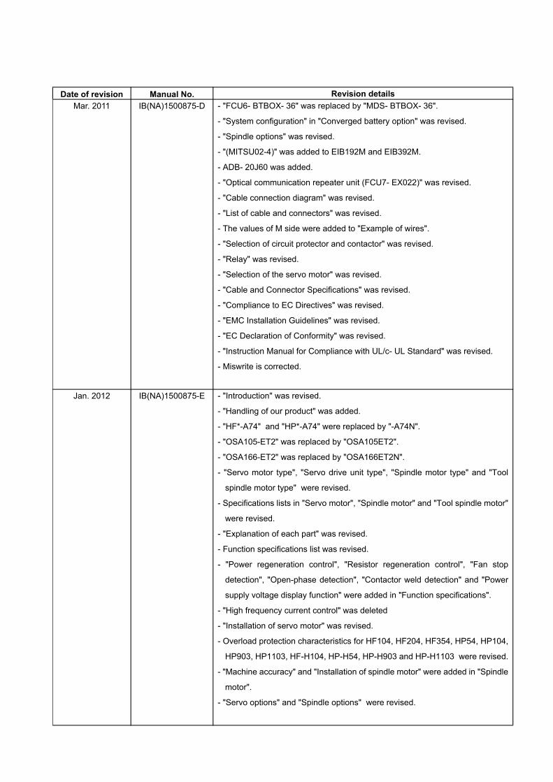
Date of revision Manual No. Revision details
Mar. 2011 IB(NA)1500875-D - "FCU6- BTBOX- 36" was replaced by "MDS- BTBOX- 36".
- "System configuration" in "Converged battery option" was revised.
- "Spindle options" was revised.
- "(MITSU02-4)" was added to EIB192M and EIB392M.
- ADB- 20J60 was added.
- "Optical communication repeater unit (FCU7- EX022)" was revised.
- "Cable connection diagram" was revised.
- "List of cable and connectors" was revised.
- The values of M side were added to "Example of wires".
- "Selection of circuit protector and contactor" was revised.
- "Relay" was revised.
- "Selection of the servo motor" was revised.
- "Cable and Connector Specifications" was revised.
- "Compliance to EC Directives" was revised.
- "EMC Installation Guidelines" was revised.
- "EC Declaration of Conformity" was revised.
- "Instruction Manual for Compliance with UL/c- UL Standard" was revised.
- Miswrite is corrected.
Jan. 2012 IB(NA)1500875-E - "Introduction" was revised.
- "Handling of our product" was added.
- "HF*-A74" and "HP*-A74" were replaced by "-A74N".
- "OSA105-ET2" was replaced by "OSA105ET2".
- "OSA166-ET2" was replaced by "OSA166ET2N".
- "Servo motor type", "Servo drive unit type", "Spindle motor type" and "Tool
spindle motor type" were revised.
- Specifications lists in "Servo motor", "Spindle motor" and "Tool spindle motor"
were revised.
- "Explanation of each part" was revised.
- Function specifications list was revised.
- "Power regeneration control", "Resistor regeneration control", "Fan stop
detection", "Open-phase detection", "Contactor weld detection" and "Power
supply voltage display function" were added in "Function specifications".
- "High frequency current control" was deleted
- "Installation of servo motor" was revised.
- Overload protection characteristics for HF104, HF204, HF354, HP54, HP104,
HP903, HP1103, HF-H104, HP-H54, HP-H903 and HP-H1103 were revised.
- "Machine accuracy" and "Installation of spindle motor" were added in "Spindle
motor".
- "Servo options" and "Spindle options" were revised.
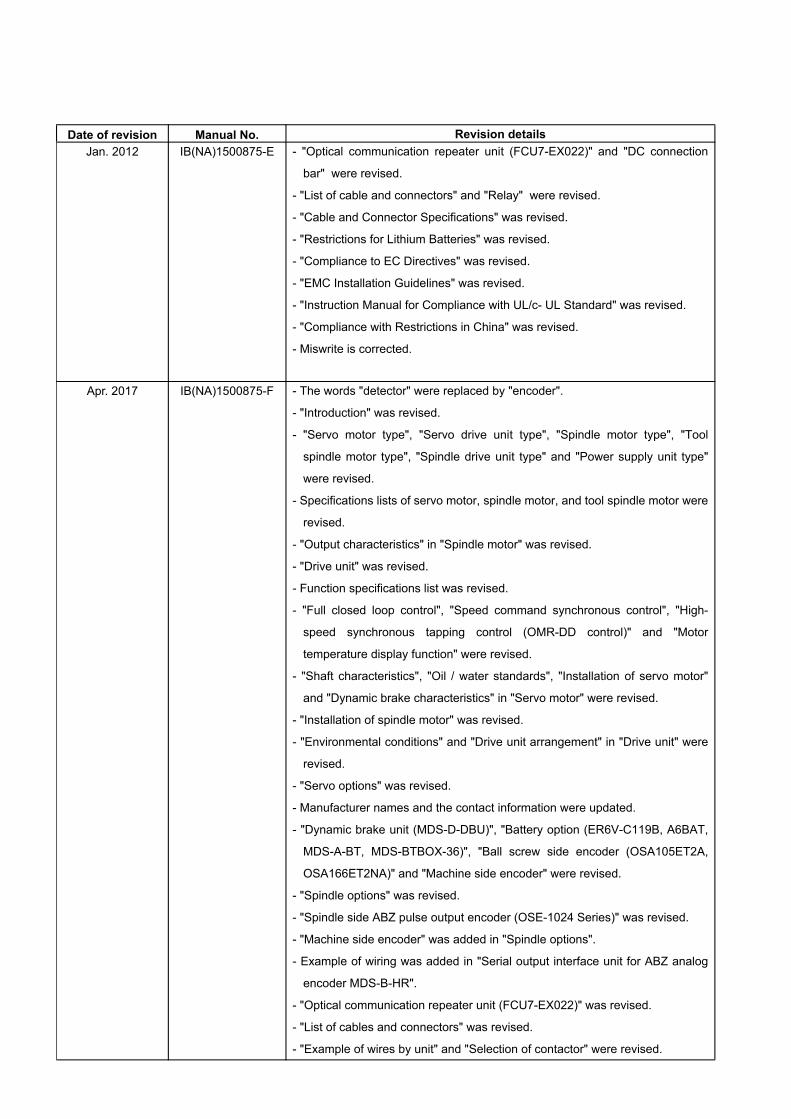
Date of revision Manual No. Revision details
Jan. 2012 IB(NA)1500875-E - "Optical communication repeater unit (FCU7-EX022)" and "DC connection
bar" were revised.
- "List of cable and connectors" and "Relay" were revised.
- "Cable and Connector Specifications" was revised.
- "Restrictions for Lithium Batteries" was revised.
- "Compliance to EC Directives" was revised.
- "EMC Installation Guidelines" was revised.
- "Instruction Manual for Compliance with UL/c- UL Standard" was revised.
- "Compliance with Restrictions in China" was revised.
- Miswrite is corrected.
Apr. 2017 IB(NA)1500875-F - The words "detector" were replaced by "encoder".
- "Introduction" was revised.
- "Servo motor type", "Servo drive unit type", "Spindle motor type", "Tool
spindle motor type", "Spindle drive unit type" and "Power supply unit type"
were revised.
- Specifications lists of servo motor, spindle motor, and tool spindle motor were
revised.
- "Output characteristics" in "Spindle motor" was revised.
- "Drive unit" was revised.
- Function specifications list was revised.
- "Full closed loop control", "Speed command synchronous control", "High-
speed synchronous tapping control (OMR-DD control)" and "Motor
temperature display function" were revised.
- "Shaft characteristics", "Oil / water standards", "Installation of servo motor"
and "Dynamic brake characteristics" in "Servo motor" were revised.
- "Installation of spindle motor" was revised.
- "Environmental conditions" and "Drive unit arrangement" in "Drive unit" were
revised.
- "Servo options" was revised.
- Manufacturer names and the contact information were updated.
- "Dynamic brake unit (MDS-D-DBU)", "Battery option (ER6V-C119B, A6BAT,
MDS-A-BT, MDS-BTBOX-36)", "Ball screw side encoder (OSA105ET2A,
OSA166ET2NA)" and "Machine side encoder" were revised.
- "Spindle options" was revised.
- "Spindle side ABZ pulse output encoder (OSE-1024 Series)" was revised.
- "Machine side encoder" was added in "Spindle options".
- Example of wiring was added in "Serial output interface unit for ABZ analog
encoder MDS-B-HR".
- "Optical communication repeater unit (FCU7-EX022)" was revised.
- "List of cables and connectors" was revised.
- "Example of wires by unit" and "Selection of contactor" were revised.

Date of revision Manual No. Revision details
Apr. 2017 IB(NA)1500875-F - "Surge absorber" was revised.
- "Selection of the servo motor" and "Selection of the power supply unit" were
revised.
- "Cable and Connector Specifications" was revised.
- "Restrictions for Lithium Batteries" was revised.
- "Compliance to EC Directives" and "EMC Installation Guidelines" were
deleted.
- "EC Declaration of Conformity" was revised.
- "Instruction Manual for Compliance with UL/c-UL Standard" was revised.
- "Global Service Network" was revised.
- Miswrite is corrected.

Global Service Network
AMERICA EUROPE
MITSUBISHI ELECTRIC AUTOMATION INC. (AMERICA FA CENTER) MITSUBISHI ELECTRIC EUROPE B.V. Central Region Service Center (Chicago) European Service Headquarter (Dusseldorf, GERMANY) 500 CORPORATE WOODS PARKWAY, VERNON HILLS, ILLINOIS 60061, U.S.A. Mitsubishi-Electric-Platz 1 40882 RATINGEN, GERMANY TEL: +1-847-478-2500 / FAX: +1-847-478-2650 TEL: +49-2102-486-1850 / FAX: +49-2102-486-5910 Minneapolis, MN Service Satellite Detroit, MI Service Satellite South Germany Service Center (Stuttgart) Grand Rapids, MI Service Satellite KURZE STRASSE. 40, 70794 FILDERSTADT-BONLANDEN, GERMANY Lima, OH Service Satellite TEL: + 49-711-770598-123 / FAX: +49-711-770598-141 Cleveland, OH Service Satellite Indianapolis, IN Service Satellite France Service Center (Paris) St. Louis, MO Service Satellite 25, BOULEVARD DES BOUVETS, 92741 NANTERRE CEDEX FRANCE
TEL: +33-1-41-02-83-13 / FAX: +33-1-49-01-07-25South/East Region Service Center (Georgia) 1845 SATTELITE BOULEVARD STE. 450, DULUTH, GEORGIA 30097, U.S.A. France Service Satellite (Lyon) TEL +1-678-258-4529 / FAX +1-678-258-4519 120, ALLEE JACQUES MONOD 69800 SAINT PRIEST FRANCE Charleston, SC Service Satellite TEL: +33-1-41-02-83-13 / FAX: +33-1-49-01-07-25 Charlotte, NC Service Satellite Raleigh, NC Service Satellite Italy Service Center (Milan) Dallas, TX Service Satellite VIALE COLLEONI, 7 - CENTRO DIREZIONALE COLLEONI PALAZZO SIRIO INGRESSO 1, Houston, TX Service Satellite 20864 AGRATE BRIANZA (MB), ITALY Hartford, CT Service Satellite TEL: +39-039-6053-342 / FAX: +39-039-6053-206 Knoxville, TN Service Satellite Nashville, TN Service Satellite Italy Service Satellite (Padova) Baltimore, MD Service Satellite VIA G. SAVELLI, 24 - 35129 PADOVA, ITALY Pittsburg, PA Service Satellite TEL: +39-039-6053-342 / FAX: +39-039-6053-206 Allentown, PA Service Satellite Syracuse, NY Service Satellite U.K. Service Center Tampa, FL Service Satellite TRAVELLERS LANE, HATFIELD, HERTFORDSHIRE, AL10 8XB, U.K. Lafayette, LA Service Satellite TEL: +49-2102-486-1850 / FAX: +49-2102-486-5910
Western Region Service Center (California) Spain Service Center 5900-B KATELLA AVE. - 5900-A KATELLA AVE. CYPRESS, CALIFORNIA 90630, U.S.A. CTRA. DE RUBI, 76-80-APDO. 420, 08173 SAINT CUGAT DEL VALLES, BARCELONA SPAIN TEL: +1-714-699-2625 / FAX: +1-847-478-2650 TEL: +34-935-65-2236 / FAX: +34-935-89-1579 San Francisco, CA Service Satellite Seattle, WA Service Satellite Poland Service Center
UL.KRAKOWSKA 50, 32-083 BALICE, POLANDCanada Region Service Center (Tronto) TEL: +48-12-347-6500 / FAX: +48-12-630-4701 4299 14TH AVENUE MARKHAM, ONTARIO L3R OJ2, CANADA TEL: +1-905-754-3805 / FAX: +1-905-475-7935 Hungary Service Center Edmonton, AB Service Satellite MADARASZ VIKTOR 47-49 , BUDAPEST XIII; HUNGARY Montreal, QC Service Satellite TEL: +48-12-347-6500 / FAX: +48-12-630-4701
Mexico Region Service Center (Queretaro) MITSUBISHI ELECTRIC TURKEY A.Ş Parque Tecnológico Innovación Querétaro, Lateral Carretera Estatal 431, Km 2+200, Lote 91 Modulos 1 y 2 Turkey Service Center Hacienda la Machorra, CP 76246, El Marqués, Querétaro, México SERIFALI MAHALLESI NUTUK SOKAK. NO.5 34775 TEL: +52-442-153 4250 UMRANIYE, ISTANBUL, TURKEY Monterrey, NL Service Satellite TEL: +90-216-526-3990 / FAX: +90-216-526-3995 Mexico City, DF Service Satellite
Czech Republic Service Center AutoCont Control Systems s.r.o (Service Partner) KAFKOVA 1853/3, 702 00 OSTRAVA 2, CZECH REPUBLIC
BRAZIL TEL: +420-59-5691-185 / FAX: +420-59-5691-199
Mitsubishi Electric do Brasil Comércio e Serviços Ltda. Russia Service CenterVotorantim Office NC-TECH (Service Partner) AV. GISELE CONSTANTINO,1578, PARQUE BELA VISTA, VOTORANTIM-SP, BRAZIL CEP:18.110-650 213, B.NOVODMITROVSKAYA STR., 14/2, 127015 MOSCOW, RUSSIA TEL: +55-15-3023-9000 TEL: +7-495-748-0191 / FAX: +7-495-748-0192 JOVIMAQ – Joinville, SC Service Satellite MAQSERVICE – Canoas, RS Service Satellite Sweden Service Center
HAMMARBACKEN 14, P.O.BOX 750 SE-19127, SOLLENTUNA, SWEDEN TEL: +46-8-6251000 / FAX: +46-8-966877
Bulgaria Service Center AKHNATON Ltd. (Service Partner) 4 ANDREJ LJAPCHEV BLVD. POB 21, BG-1756 SOFIA, BULGARIA TEL: +359-2-8176009 / FAX: +359-2-9744061
Ukraine Service Center (Kharkov) CSC Automation Ltd. (Service Partner) APTEKARSKIY PEREULOK 9-A, OFFICE 3, 61001 KHARKOV, UKRAINE TEL: +380-57-732-7774 / FAX: +380-57-731-8721
Belarus Service Center TECHNIKON Ltd. (Service Partner) NEZAVISIMOSTI PR.177, 220125 MINSK, BELARUS TEL: +375-17-393-1177 / FAX: +375-17-393-0081
South Africa Service Center MOTIONTRONIX (Service Partner) P.O. BOX 9234, EDLEEN, KEMPTON PARK GAUTENG, 1625, SOUTH AFRICA TEL: +27-11-394-8512 / FAX: +27-11-394-8513
ASEAN CHINA
MITSUBISHI ELECTRIC ASIA PTE. LTD. (ASEAN FA CENTER) MITSUBISHI ELECTRIC AUTOMATION (CHINA) LTD. (CHINA FA CENTER)Singapore Service Center China Shanghai Service Center 307 ALEXANDRA ROAD #05-01/02 MITSUBISHI ELECTRIC BUILDING SINGAPORE 159943 1-3,5-10,18-23/F, NO.1386 HONG QIAO ROAD, CHANG NING QU, TEL: +65-6473-2308 / FAX: +65-6476-7439 SHANGHAI 200336, CHINA
TEL: +86-21-2322-3030 / FAX: +86-21-2322-3000*8422Philippines Service Center China Ningbo Service Partner Flexible (Service Partner) China Wuxi Service Partner UNIT NO.411, ALABAMG CORPORATE CENTER KM 25. WEST SERVICE ROAD China Jinan Service Partner SOUTH SUPERHIGHWAY, ALABAMG MUNTINLUPA METRO MANILA, PHILIPPINES 1771 China Hangzhou Service Partner TEL: +63-2-807-2416 / FAX: +63-2-807-2417
China Beijing Service Center 9/F, OFFICE TOWER 1, HENDERSON CENTER, 18 JIANGUOMENNEI DAJIE,
VIETNAM DONGCHENG DISTRICT, BEIJING 100005, CHINA TEL: +86-10-6518-8830 / FAX: +86-10-6518-8030
MITSUBISHI ELECTRIC VIETNAM CO.,LTD China Beijing Service PartnerVietnam Ho Chi Minh Service Center UNIT 01-04, 10TH FLOOR, VINCOM CENTER 72 LE THANH TON STREET, DISTRICT 1, China Tianjin Service Center HO CHI MINH CITY, VIETNAM UNIT 2003, TIANJIN CITY TOWER, NO 35 YOUYI ROAD, HEXI DISTRICT, TEL: +84-8-3910 5945 / FAX: +84-8-3910 5946 TIANJIN 300061, CHINA
TEL: +86-22-2813-1015 / FAX: +86-22-2813-1017Vietnam Hanoi Service Center 6TH FLOOR, DETECH TOWER, 8 TON THAT THUYET STREET, MY DINH 2 WARD, China Chengdu Service Center NAM TU LIEM DISTRICT, HA NOI CITY, VIETNAM 1501-1503,15F,GUANG-HUA CENTRE BUILDING-C,NO.98 NORTH GUANG HUA 3th RD, TEL: +84-4-3937-8075 / FAX: +84-4-3937-8076 CHENGDU,610000,CHINA
TEL: +86-28-8446-8030 / FAX: +86-28-8446-8630
INDONESIA China Shenzhen Service Center ROOM 2512-2516, 25/F., GREAT CHINA INTERNATIONAL EXCHANGE SQUARE, JINTIAN RD.S.,
PT. MITSUBISHI ELECTRIC INDONESIA FUTIAN DISTRICT, SHENZHEN 518034, CHINAIndonesia Service Center (Cikarang) TEL: +86-755-2399-8272 / FAX: +86-755-8229-3686 JL. KENARI RAYA BLOK G2-07A, DELTA SILICON 5, LIPPO CIKARANG - BEKASI 17550, INDONESIA China Xiamen Service Partner TEL: +62-21-2961-7797 / FAX: +62-21-2961-7794 China DongGuang Service Partner
China Dalian Service Center MALAYSIA DONGBEI 3-5, DALIAN ECONOMIC & TECHNICAL DEVELOPMENTZONE, LIAONING PROVINCE,
116600, CHINAMITSUBISHI ELECTRIC SALES MALAYSIA SDN. BHD. TEL: +86-411-8765-5951 / FAX: +86-411-8765-5952Malaysia Service Center (Kuala Lumpur Service Center) LOT 11, JALAN 219, P.O BOX 1036, 46860 PETALING JAYA, SELANGOR DARUL EHSAN. MALAYSIA TEL: +60-3-7960-2628 / FAX: +60-3-7960-2629 KOREA Johor Bahru Service satellite
MITSUBISHI ELECTRIC AUTOMATION KOREA CO., LTD. (KOREA FA CENTER)Korea Service Center
THAILAND 8F GANGSEO HANGANG XI-TOWER A, 401 YANGCHEON-RO, GANGSEO-GU, SEOUL 07528 KOREA
MITSUBISHI ELECTRIC FACTORY AUTOMATION (THAILAND) CO.,LTD TEL: +82-2-3660-9609 / FAX: +82-2-3664-8668Thailand Service Center Korea Daegu Service Satellite 12TH FLOOR, SV.CITY BUILDING, OFFICE TOWER 1, NO. 896/19 AND 20 RAMA 3 ROAD, KWAENG BANGPONGPANG, KHET YANNAWA, BANGKOK 10120,THAILAND TEL: +66-2-682-6522 / FAX: +66-2-682-6020 TAIWAN
MITSUBISHI ELECTRIC TAIWAN CO., LTD. (TAIWAN FA CENTER) INDIA Taiwan Taichung Service Center
NO.8-1, INDUSTRIAL 16TH RD., TAICHUNG INDUSTRIAL PARK, SITUN DIST., MITSUBISHI ELECTRIC INDIA PVT., LTD. TAICHUNG CITY 40768, TAIWANCNC Technical Center (Bangalore) TEL: +886-4-2359-0688 / FAX: +886-4-2359-0689 PLOT NO. 56, 4TH MAIN ROAD, PEENYA PHASE 3, PEENYA INDUSTRIAL AREA, BANGALORE 560058, KARNATAKA, INDIA Taiwan Taipei Service Center TEL : +91-80-4655-2121 FAX : +91-80-4655-2147 10F, NO.88, SEC.6, CHUNG-SHAN N. RD., SHI LIN DIST., TAIPEI CITY 11155, TAIWAN Chennai Service Satellite TEL: +886-2-2833-5430 / FAX: +886-2-2833-5433 Coimbatore Service Satellite Hyderabad Service Satellite Taiwan Tainan Service Center
11F-1., NO.30, ZHONGZHENG S. ROAD, YONGKANG DISTRICT, TAINAN CITY 71067, TAIWANNorth India Service Center (Gurgaon) TEL: +886-6-252-5030 / FAX: +886-6-252-5031 2ND FLOOR, TOWER A&B, DLF CYBER GREENS, DLF CYBER CITY, DLF PHASE-III, GURGAON- 122 002, HARYANA, INDIA TEL : +91-124-4630 300 FAX : +91-124-4630 399 OCEANIA Ludhiana Satellite Panth Nagar Service Satellite MITSUBISHI ELECTRIC AUSTRALIA PTY. LTD. Delhi Service Satellite Oceania Service Center Jamshedpur Service Satellite 348 VICTORIA ROAD, RYDALMERE, N.S.W. 2116 AUSTRALIA
TEL: +61-2-9684-7269/ FAX: +61-2-9684-7245West India Service Center (Pune) EMERALD HOUSE, EL-3, J BLOCK, M.I.D.C., BHOSARI, PUNE - 411026, MAHARASHTRA, INDIA TEL : +91-20-2710 2000 FAX : +91-20-2710 2100 Kolhapur Service Satellite Aurangabad Service Satellite Mumbai Service Satellite
West India Service Center (Ahmedabad) UNIT NO: B/4, 3RD FLOOR, SAFAL PROFITAIRE, PRAHALADNAGAR CORPORATE ROAD, PRAHALADNAGAR SATELLITE, AHMEDABAD – 380015, GUJRAT, INDIA TEL : +91-265-2314699 Rajkot Service Satellite

Notice
Every effort has been made to keep up with software and hardware revisions in thecontents described in this manual. However, please understand that in someunavoidable cases simultaneous revision is not possible. Please contact your Mitsubishi Electric dealer with any questions or commentsregarding the use of this product.
Duplication Prohibited
This manual may not be reproduced in any form, in part or in whole, without writtenpermission from Mitsubishi Electric Corporation.
© 2008 - 2017 Mitsubishi Electric CorporationALL RIGHTS RESERVED

Related Documents


![DIRECCIONES - Ancoil...DH - 3085 DH - 3100 DH - 3150 DH - 3200 DH - 3250 DH - 3300 DH - 3350 DH - 3400 DH - 3450 DH - 3500 TIPO DE UNIDAD DESPLAZAMIENTO VOLUMETRICO REAL [cm3/rev.]](https://static.cupdf.com/doc/110x72/613e751469193359046d2218/direcciones-ancoil-dh-3085-dh-3100-dh-3150-dh-3200-dh-3250-dh-.jpg)


