MDA-based Configuration of Distributed Real-time and Embedded Systems Brian Dougherty, Jules White, and Douglas C. Schmidt Institute for Software Integrated Systems Vanderbilt University, Nashville, TN 37203, USA {briand, jules, schmidt}@dre.vanderbilt.edu Abstract Distributed real-time and embedded (DRE) systems are increasingly being constructed with commercial- off-the-shelf (COTS) components to reduce development time and effort. The configuration of these compo- nents must ensure that real-time quality-of-service (QoS) and resource constraints are satisfied. Due to the numerous QoS constraints that must be met, manual system configuration is hard. Model-Driven Architec- ture (MDA) is a design paradigm that incorporates models to provide visual representations of design enti- ties. MDAs show promise for addressing many of these challenges by allowing the definition and auto- mated enforcement of design constraints. This chapter presents MDA techniques and tools that simplify and automate the configuration of COTS components for DRE systems. First, we present the challenges that make manual DRE system configuration infeasible. Second, we provide an incremental methodology for constructing modeling tools to alleviate these difficulties. Finally, we provide a case study describing the construction of the Ascent Modeling Platform (AMP), which is a modeling tool capable of producing near- optimal DRE system configurations. 1. Introduction Emerging trends and challenges. Distributed real-time embedded (DRE) systems (such as avionics sys- tems, satellite imaging systems, smart cars, and intelligent transportation systems) are subject to stringent requirements and quality of service (QoS) constraints. For example, timing constraints require that tasks be completed by real-time deadlines. Likewise, rigorous QoS demands (such as dependability and security), may require a system to recover and remain active in the face of multiple failures (Wang, 2003). In addi- tion, DRE systems must satisfy domain-specific constraints, such as the need for power management in embedded systems. To cope with these complex issues, applications for DRE systems have traditionally been built from scratch using specialized, project-specific software components that are tightly coupled with specialized hardware components (Schmidt, 2002). New DRE systems are increasingly being developed by configuring applications from multiple layers of commercial-off-the-shelf (COTS) hardware, operating systems, and middleware components resulting in reduced development cycle-time and cost (Voas, 1998). These types of DRE systems require the integra- tion of 100’s-1,000’s of software components that provide distinct functionality, such as I/O, data manipu- lation, and data transfer. This functionality must work in concert with other software and hardware compo- nents to accomplish mission-critical tasks, such as self-stabilization, error notification, and power manage- ment. The software configuration of a DRE system thus directly impacts its performance, cost, and quality. Traditionally, DRE systems have been built completely in-house from scratch. These design techniques are based on in-house proprietary construction techniques and are not designed to handle the complexities of configuring systems from existing components (Gokhale, 2002). The new generation of configuration- based approaches construct DRE systems by determining which combination of hardware/software compo- nents provide the requisite QoS (Alves, 2001, Chung, 2004, Morisio, 2002), In addition, the combined pur- chase cost of the components cannot exceed a predefined amount, referred to as the project budget. A DRE system can be split into a software configuration and a hardware configuration. A valid software configuration must meet all real-time constraints, such as minimum latency and maximum throughput, pro- vide required functionality, and also satisfy all domain-specific design constraints, such as maximum power consumption. Moreover, the cost of the software configuration must not exceed the available budget for purchasing software components. Similarly, the hardware configuration must meet all constraints without exceeding the available hardware component budget. At the same time, the hardware and software configu- ration must be aligned so that the hardware configuration provides sufficient resources, such as RAM, for the chosen software configuration.

Welcome message from author
This document is posted to help you gain knowledge. Please leave a comment to let me know what you think about it! Share it to your friends and learn new things together.
Transcript
MDA-based Configuration of Distributed Real-time and Embedded Systems
Brian Dougherty, Jules White, and Douglas C. Schmidt Institute for Software Integrated Systems
Vanderbilt University, Nashville, TN 37203, USA {briand, jules, schmidt}@dre.vanderbilt.edu
Abstract
Distributed real-time and embedded (DRE) systems are increasingly being constructed with commercial-off-the-shelf (COTS) components to reduce development time and effort. The configuration of these compo-nents must ensure that real-time quality-of-service (QoS) and resource constraints are satisfied. Due to the numerous QoS constraints that must be met, manual system configuration is hard. Model-Driven Architec-ture (MDA) is a design paradigm that incorporates models to provide visual representations of design enti-ties. MDAs show promise for addressing many of these challenges by allowing the definition and auto-mated enforcement of design constraints. This chapter presents MDA techniques and tools that simplify and automate the configuration of COTS components for DRE systems. First, we present the challenges that make manual DRE system configuration infeasible. Second, we provide an incremental methodology for constructing modeling tools to alleviate these difficulties. Finally, we provide a case study describing the construction of the Ascent Modeling Platform (AMP), which is a modeling tool capable of producing near-optimal DRE system configurations.
1. Introduction Emerging trends and challenges. Distributed real-time embedded (DRE) systems (such as avionics sys-tems, satellite imaging systems, smart cars, and intelligent transportation systems) are subject to stringent requirements and quality of service (QoS) constraints. For example, timing constraints require that tasks be completed by real-time deadlines. Likewise, rigorous QoS demands (such as dependability and security), may require a system to recover and remain active in the face of multiple failures (Wang, 2003). In addi-tion, DRE systems must satisfy domain-specific constraints, such as the need for power management in embedded systems. To cope with these complex issues, applications for DRE systems have traditionally been built from scratch using specialized, project-specific software components that are tightly coupled with specialized hardware components (Schmidt, 2002).
New DRE systems are increasingly being developed by configuring applications from multiple layers of commercial-off-the-shelf (COTS) hardware, operating systems, and middleware components resulting in reduced development cycle-time and cost (Voas, 1998). These types of DRE systems require the integra-tion of 100’s-1,000’s of software components that provide distinct functionality, such as I/O, data manipu-lation, and data transfer. This functionality must work in concert with other software and hardware compo-nents to accomplish mission-critical tasks, such as self-stabilization, error notification, and power manage-ment. The software configuration of a DRE system thus directly impacts its performance, cost, and quality.
Traditionally, DRE systems have been built completely in-house from scratch. These design techniques are based on in-house proprietary construction techniques and are not designed to handle the complexities of configuring systems from existing components (Gokhale, 2002). The new generation of configuration-based approaches construct DRE systems by determining which combination of hardware/software compo-nents provide the requisite QoS (Alves, 2001, Chung, 2004, Morisio, 2002), In addition, the combined pur-chase cost of the components cannot exceed a predefined amount, referred to as the project budget.
A DRE system can be split into a software configuration and a hardware configuration. A valid software configuration must meet all real-time constraints, such as minimum latency and maximum throughput, pro-vide required functionality, and also satisfy all domain-specific design constraints, such as maximum power consumption. Moreover, the cost of the software configuration must not exceed the available budget for purchasing software components. Similarly, the hardware configuration must meet all constraints without exceeding the available hardware component budget. At the same time, the hardware and software configu-ration must be aligned so that the hardware configuration provides sufficient resources, such as RAM, for the chosen software configuration.

Often, there are multiple COTS components that can meet each functional requirement for a DRE system. Each individual COTS component differs in QoS provided, the amounts/types of computational resources required, and the purchase cost. Creating and maintaining error-free COTS configurations is hard due to the large number of complex configuration rules and QoS requirements. The complexity associated with ex-amining the tradeoffs of choosing between 100’s to 1,000’s of COTS components makes it hard to deter-mine a configuration that satisfies all constraints and is not needlessly expensive or resource intensive.
Solution approach → Model-driven automated configuration techniques. This chapter presents techniques and tools that leverage the Model Driven Architecture (MDA) paradigm (Mellor, 2004), which is a design approach for specifying system configuration constraints with platform-independent models (PIMs). Each PIM can be used as a blueprint for constructing platform-specific models (PSM)s (Poole, 2001). In this chapter, we utilize MDA to construct modeling tools that can be used to create model in-stances of potential DRE system configurations. We then apply these tools in a case study to determine valid DRE system configurations that fit budget limits and ensure consistency between hardware and soft-ware component selections.
To simplify the DRE system configuration process, designers can use MDA to visualize COTS component options, verify configuration validity, and compare potential DRE system configurations. In particular, PSMs can be used to determine DRE system configurations that meet budgetary constraints by representing component selections in modeling environments. Modeling tools that utilize these environments provide a domain-centric way to experiment with and explore potential system configurations. Moreover, by con-structing PSMs with the aid of modeling tools, many complex constraints associated with DRE system con-figuration can be enforced automatically, thereby preventing designers from constructing PSMs that violate system configuration rules.
After a PSM instance of a DRE system configuration is constructed, it can be used as a blueprint to con-struct a DRE system that meets all design constraints specified within the metamodel (Kent, 2002). As DRE system requirements evolve and additional constraints are introduced, the metamodel can be modified and new PSMs constructed. Systems that are constructed using these PSMs can be adapted to handle addi-tional constraints and requirements more readily than those developed manually using third-generation lan-guages, such as C++, Java, or C#.
Chapter organization . The remainder of this chapter describes and evaluates MDA-based analyses techniques for determining high quality DRE system configurations utilizing COTS components. Section 2 describes the numerous challenges that make large-scale DRE system configuration extremely difficult; Section 3 presents an incremental methodology for applying MDA to the construction of domain specific modeling tools; Section 4 provides a case study of utilizing this methodology to construct a model-based configuration tool which can ultimately be used to produce output models that provide valid, high-quality large-scale DRE system configurations.; Section 5 describes future work; and Section 6 presents conclud-ing remarks and lessons learned.
2. Large-scale DRE System Configuration Challenges. This section describes some key constraints that DRE systems must adhere to, summarizes the challenges that make determining configurations hard, and provides a survey of current techniques and methodologies for DRE system configuration. A DRE system configuration consists of a valid hardware configuration and valid software configuration in which the computational resource needs of the software configuration are provided by the computational resources produced by the hardware configuration. DRE system software and hardware components often have complex interdependencies on the consumption and production of re-sources (such as processor utilization, memory usage, and power consumption). If the resource require-ments of the software configuration exceed the resource production of the hardware configuration, a DRE system will not function correctly and will thus be invalid.
2.1 Challenge 1: Resource Interdependencies
Hardware components provide the computational resources that software components require to function. If the hardware does not provide an adequate amount of each computational resource, some software compo-nents cannot function. An overabundance of resources indicates that some hardware components have been

purchased unnecessarily, wasting funds that could have been spent to buy superior software components or set aside for future projects.
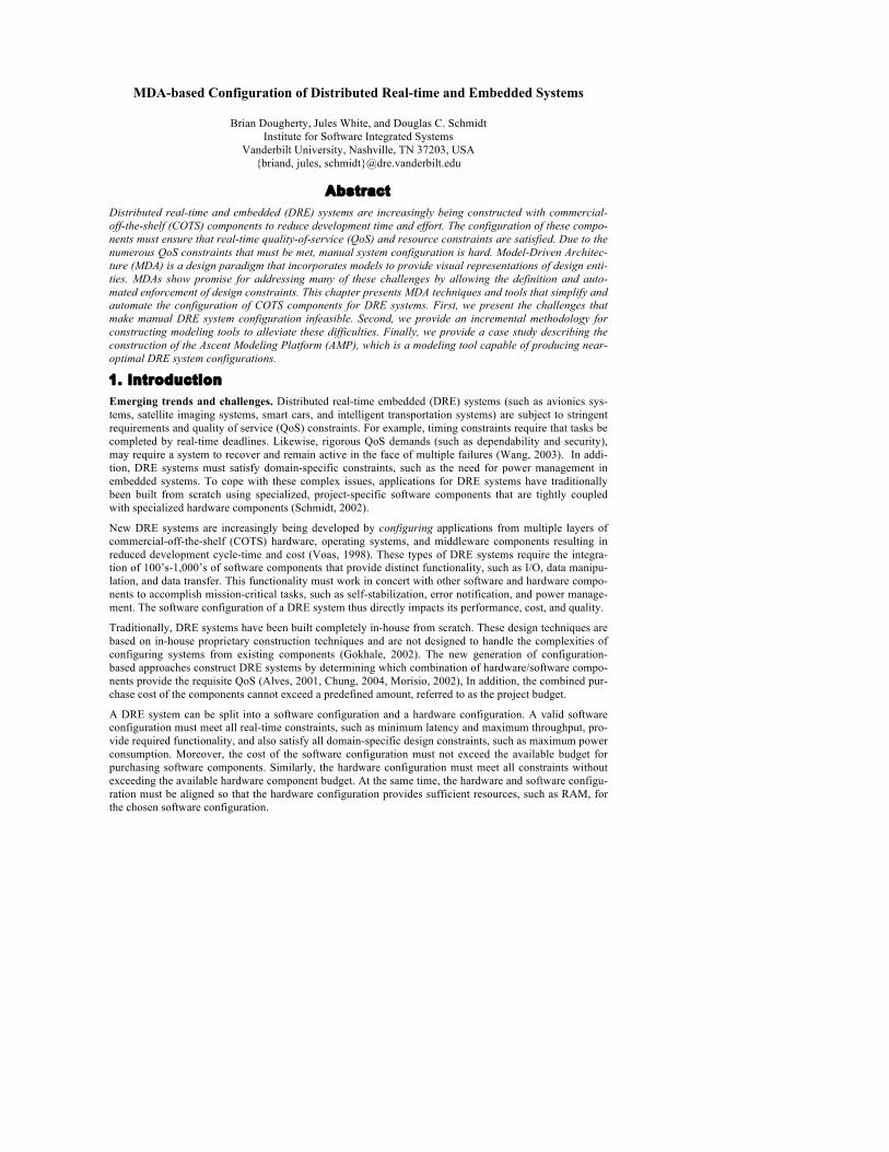
Figure 1 shows the configuration options of a satellite imaging system. This DRE system consists of an image processing algorithm and software that defines image resolution capabilities. There are multiple components that could be used to meet each functional requirement, each of which provides a different level of service. For example, there are three options for the image resolution component. The high-resolu-tion option offers the highest level of service, but also requires dramatically more RAM and CPU to func-tion than the medium or low-resolution options. If the resource amounts required by the high-resolution option are not supplied, then the component cannot function, preventing the system from functioning cor-rectly. If RAM or CPU resources are scarce the medium or low-resolution option should be chosen.
Figure 1. Configuration Options of a Satellite Imaging System. 2.2 Challenge 2: Component Resource Requirements Differ
Each software component requires computational resources to function. These resource requirements differ between components. Often, components offering higher levels of service require larger amounts of re-sources and/or cost more to purchase. Designers must therefore consider the additional resulting resource requirements when determining if a component can be included in a system configuration.
For example, the satellite system shown in Figure 1 has three options for the image resolution software component, each of which provides a different level of performance. If resources were abundant, the sys-tem with the best performance would result from selecting the high-resolution component. In most DRE systems, such as satellite systems, resources are scarce and cannot be augmented without great cost and effort. While the performance of the low-resolution component is less than that of the high-resolution com-ponent, it requires a fraction of the computational resources. If any resource requirements are not satisfied, the system configuration is considered invalid. A valid configuration is thus more likely to exist by select-ing the low-resolution component.
2.3 Challenge 3: Selecting Between Differing Levels of Service
Software components provide differing levels of service. For example, a designer may have to choose be-tween three different software components that differ in speed and throughput. In some cases, a specific level of service may be required, prohibiting the use of certain components.
Continuing with the satellite configuration example shown in Figure 1, an additional functional constraint may require that a minimum of medium image resolution. Inclusion of the low-resolution component would therefore invalidate the overall system configuration. Assuming sufficient resources for only the medium and low-resolution components, the only component that satisfies all constraints is the medium image resolution option.

Moreover, the inclusion of a component in a configuration may prohibit or require the use one or more oth-er components. Certain software components may have compatibility problems with other components. For example, each of the image resolution components may be a product of separate vendors. As a result, the high and medium-resolution components may be compatible with any image processing component, whe-reas the low-resolution component may only be compatible with image processing components made by the same vendor. These compatibility issues add another level of difficulty to determining valid DRE sys-tem configurations.
2.4 Challenge 4: Configuration Cannot Exceed Project Budget
Each component has an associated purchase cost. The combined purchase cost of the components included in the configuration must not exceed the project budget. It is therefore possible for the inclusion of a com-ponent to invalidate the configuration if its additional purchase cost exceeds the project budget regardless of computational resources existing to support the component. Moreover, if two systems have roughly the same resource requirements and performance the system that carries a smaller purchase cost is considered superior.
Another challenge of meeting budgetary constraints is determining the best way to allocate the budget be-tween hardware purchases and software purchases. Despite the presence of complex resource interdepen-dencies, most techniques require that the selection of the software configuration and hardware configura-tion occur separately. For example, the hardware configuration could be determined prior to the software configuration so that the resource availability of the system is known prior to solving for a valid software configuration. Conversely, the software configuration could be determined initially so that the resource requirements of the system are known prior to solving for the hardware configuration.
To solve for a hardware or software configuration individually, the total project budget must be divided into a software budget for purchasing software components and a hardware budget for purchasing hardware components. Dividing the budget evenly between the two configuration problems may not produce a valid configuration. Uneven budget divisions, however, may result in valid system configurations. Multiple budget divisions must therefore be examined.
2.5 Challenge 5: Exponential Configuration Space
Large-scale DRE systems require hundreds of components to function. For each component there may be many components available for inclusion in the final system configuration. Due to the complex resource in-terdependencies, budgetary constraints, and functional constraints it is hard to determine if including a sin-gle component will invalidate the system configuration. This problem is exacerbated enormously if design-ers are faced with the tasks of choosing from 1,000’s of available components. Even automated techniques require years or more to examine all possible system configurations for such problems.
Large-scale DRE systems often also consist of many software and hardware components with multiple op-tions for each component, resulting in an exponential number of potential configurations. Due to the mul-tiple functional, real-time, and resource constraints discussed earlier, arbitrarily selecting components for a configuration is ineffective. For example, if there are 100 components to choose from then there are 1.2676506 × 1030 unique potential system configurations, the vast majority of which are invalid configura-tions.
The huge magnitude of the solution space prohibits the use of manual techniques. Automated techniques, such as Constraint Logic Programming (CLP), use Constraint Satisfaction Problems (CSPs) to represent system configuration problems (Benavides, 2005, Sabin, 1996). These techniques are capable of determin-ing optimal solutions for small-scale system configurations but require the examination of all potential sys-tem configurations. Techniques utilizing CSPs are ideal, however, for system configuration problems in-volving a small number of components as they can determine an optimal configuration—should one ex-ist—in a short amount of time.
The exhaustive nature of conventional CSP-based techniques, however, renders them ineffective for large-scale DRE system configuration. Without tools to aid in large-scale DRE system configuration, it is hard for designers to determine any valid large-scale system configuration. Even if a valid configuration is de-termined, other valid system configurations may exist with vastly superior performance and dramatically less financial cost. Moreover, with constant development of additional technologies, legacy technologies
becoming unavailable, and design objectives constantly in flux, valid configurations can quickly become invalid, requiring that new configurations be discovered rapidly. It is thus imperative that advanced design techniques, utilizing MDA, are developed to enhance and validate large-scale DRE system configurations.
Subsequent sections of this chapter demonstrate how MDA can be utilized to mitigate many difficulties of DRE system configuration that result from the challenges described in this section.
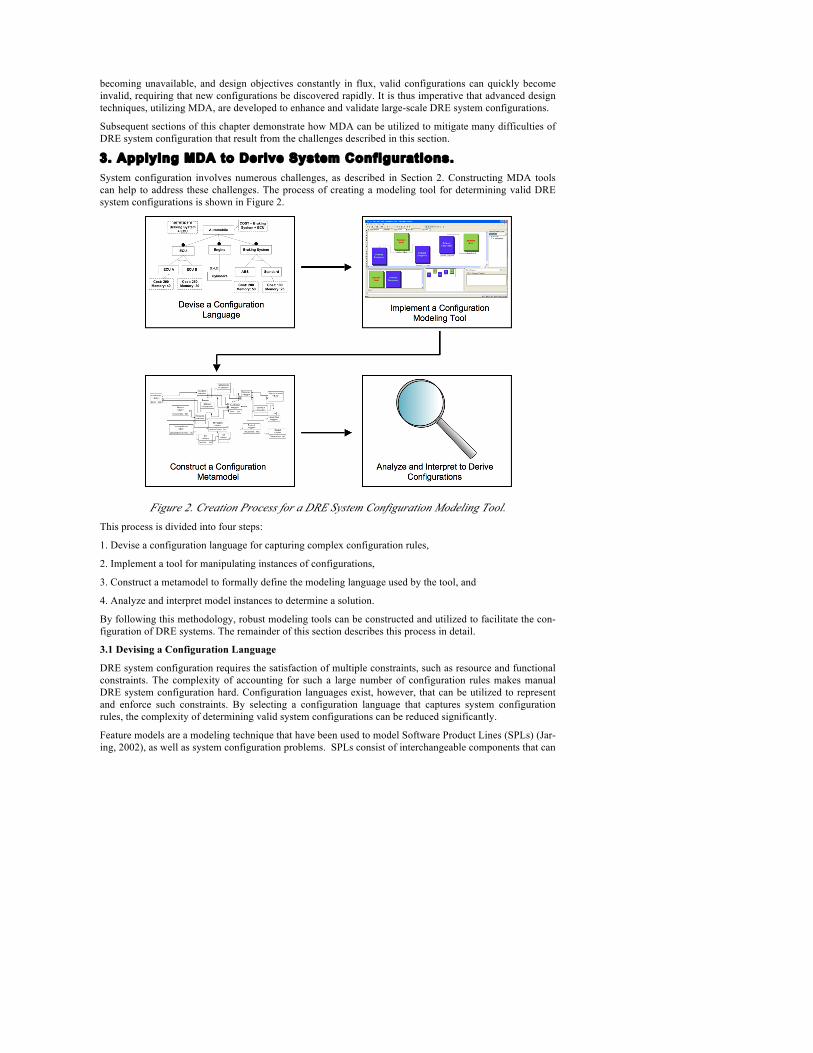
3. Applying MDA to Derive System Configurations. System configuration involves numerous challenges, as described in Section 2. Constructing MDA tools can help to address these challenges. The process of creating a modeling tool for determining valid DRE system configurations is shown in Figure 2.
Figure 2. Creation Process for a DRE System Configuration Modeling Tool.
This process is divided into four steps:
1. Devise a configuration language for capturing complex configuration rules,
2. Implement a tool for manipulating instances of configurations,
3. Construct a metamodel to formally define the modeling language used by the tool, and
4. Analyze and interpret model instances to determine a solution.
By following this methodology, robust modeling tools can be constructed and utilized to facilitate the con-figuration of DRE systems. The remainder of this section describes this process in detail.
3.1 Devising a Configuration Language
DRE system configuration requires the satisfaction of multiple constraints, such as resource and functional constraints. The complexity of accounting for such a large number of configuration rules makes manual DRE system configuration hard. Configuration languages exist, however, that can be utilized to represent and enforce such constraints. By selecting a configuration language that captures system configuration rules, the complexity of determining valid system configurations can be reduced significantly.
Feature models are a modeling technique that have been used to model Software Product Lines (SPLs) (Jar-ing, 2002), as well as system configuration problems. SPLs consist of interchangeable components that can

be swapped to alter system functionality. Czarnecki et al. use feature models to describe the configuration options of systems (Czarnecki, 2005). Feature models are represented using tree structures with lines (rep-resenting configuration constraints) connecting candidate components for inclusion in an SPL, known as features. The feature model uses configuration constraints to depict the effects that selecting one or more features has on the validity of selecting other features. The feature model serves as a mechanism to deter-mine if the inclusion of a feature will result in an invalid system configuration. Czarnecki et al. also present staged-configuration, an incremental technique for manually determining valid feature selections. This work, however, cannot be directly applied to the configuration of large-scale DRE system configuration because it doesn’t guarantee correctness or provide a way of handling resource constraints. Moreover, it takes a prohibitive amount of time to determine valid system configurations since staged-configuration is not automated.
Benavides et al. introduce the extended feature model, an augmented feature model with the ability to more articulately define features and represent additional constraints (Benavides, 2005). Additional descriptive information, called attributes, can be added to define one or more parameters of each feature. For example, the resource consumption and cost of a feature could be defined by adding attributes to the feature. Each attribute lists the type of resource and the amount consumed or provided by the feature. Additional con-straints can be defined by adding extra-functional features. Extra-functional features define rules that dic-tate the validity of sets of attributes. For example, an extra-functional feature may require that the total cost of a set of features representing components is less than that of a feature that defines the budget. Any valid feature selection would thus satisfy the constraint that the collective cost of the components is less than the total project budget.
3.2 Implementing a Modeling Tool
Designers using manual techniques often unknowingly construct invalid system configurations. Even if an existing valid system configuration is known, the introduction of a single component can violate one or more of these constraints, thereby invalidating the entire configuration. Modeling tools allow designers to manipulate problem entities and compare potential solutions in an environment that ensures various design rules are enforced that are not accounted for in current third-generation programming languages, such as Java and C++. Automated correctness checking allows designers to focus on other problem dimensions, such as performance optimization or minimization of computational resource requirements.
One example of a modeling tool is the Generic Modeling Environment (GME) composing domain-specific design environments. (Ledeczi, 2001b) GME is modeling platform for building MDA based tools that can then be used to create model instances. The two principles components of GME are GMeta and GModel, which work together to provide this functionality. GMeta is a graphical tool for constructing metamodels, which are discussed in Section 3.3. GModel is a graphical editor for constructing model instances that ad-here to the configuration rules.
Figure 3. GME Model of DRE System Configuration.

For example, a user could construct a system configuration model that consists of hardware and software components as shown in Figure 3. By using the graphical editor, the user can manually create multiple sys-tem configuration instances. If the user attempts to include a component that violates a configuration rule, GModel will disallow the inclusion of the component and explain the violation. Since GModel is re-sponsible for enforcing all constraints, the designer can rapidly create and experiment with various models without the overhead of monitoring for constraint violations.
3.3 Constructing a Metamodel
Metamodels are used to formally define the rules that are enforced by modeling tools (Ledeczi, 2001a). This collection of rules governs the entities, relationships and constraints of model instances constructed. After constructing a metamodel, users can define modeling tools that are capable of creating model in-stances that enforce the rules and constraints defined by the metamodel.
Most nontrivial problems require multiple modeling entities, types of relationships between entities, and complex constraints. As a result, constructing metamodels can be a confusing, arduous task. Fortunately, metamodeling tools exist that provide a clear and simple procedure for creating metamodels. Tools for ge-nerating metamodels provide several advantages over defining them manually. For example, metamodeling tools can prevent defining rules, such as defining nameless entities, that are contradictory or inappropriate. Likewise, by using a metamodeling tool, metamodels can easily be augmented or altered should the domain or other problem parameters change. Moreover, the same complexities inherent to creating PSMs are also present in the construction of metamodels, and often amplified by the additional abstraction required for their creation. Metamodeling tools use an existing language that defines the rules for creating metamodels, thereby enforcing the complex constraints and facilitating quick, accurate metamodel design.
To create a metamodel for describing system configuration we must first define the entities that are in-volved in DRE system configuration. For example, at the most basic level, DRE system configuration con-sists of hardware and software components. We must then define how these entities interact. For example, we can specify that hardware components provide computational resources and that software components consume computational resources. We also need a way to define the constraints that must be maintained as these entities interact for a system configuration to be valid. For example, we may specify that a software component that interacts with a hardware component must be provided with sufficient computational re-sources to function by the hardware component.
After all the necessary entities for the modeling tool are created we must define the rules that govern the relationships of these entities. For example, we must define the relationship between hardware nodes and software components in which the software components consume resources of the hardware nodes. Before we can do this, however, we must define an attribute that specifies the resource production values of the hardware nodes and the resource consumption values of the software nodes. Once we have defined an at-tribute and associated it with a class, we can include the attribute in the relationship definition.
A relationship between two model entities is defined by adding a connection to the metamodel. The con-nection specifies the rules for connecting entities in the resulting PSM. Within the connection, we can de-fine additional constraints that must be satisfied for two classes to be connected. For example, for a soft-ware component to be connected to a hardware node the resource consumption attribute of the software component can not exceed the attribute of the hardware node that defines the amount of resource produc-tion.
GME provides GMeta, a graphical tool for constructing metamodels. GMeta divides metamodel design into four separate sub-metamodels: the Class Diagram, Visualization, Constraints, and Attributes. The Class Diagram defines the entities within the model, known as models, atoms, and first class objects as well as the connections that can be made between them. The Visualization sub-metamodel defines different as-pects, or filters, for viewing only certain entities within a model instance. For example, if defining a meta-model for a finite state machine, an aspect could be defined in the Visualization sub-metamodel that would only display accepting states in a finite state machine model instance. The Constraints sub-metamodel al-lows the application of Object Constraint Language (OCL) (Richters, 1998) constraints to metamodel enti-ties. Continuing with the finite state machine metamodel example, a constraint could be defined that only a single starting state may exist in the model. To do this, users would add a constraint in the Constraints sub-metamodel, add the appropriate OCL code to define the constraint, and then connect it to the entity to

which it applies. Finally, the Attributes sub-metamodel allows additional data, known as attributes, to be defined and associated with other metamodel entities defined in the Class Diagram.
After the metamodel has been constructed using GMeta, the interpreter must be run to convert the metamo-del into a GME paradigm. This paradigm can then be loaded with GME and used to created models that adhere to the rules defined within the metamodel. User may then create model instances with the assurance that the design rules and domain specific constraints defined within the metamodel are satisfied. If at any point the domain or design constraints of the model change, the metamodel can be reloaded, altered and interpreted again to change the GME paradigm appropriately. As a result, designers can easily examine scenarios in which constraints differ, giving a broader overview of the design space.
3.4 Analyzing and Interpreting Model Instances
After a configuration language is determined, a modeling tool implemented, and a metamodel constructed, designers can rapidly construct model instances of valid DRE system configurations. There is no guarantee, however, that the configurations constructed with these tools are optimal. For example, while a configura-tion instance may be constructed that does not violate any design constraints, other configurations may ex-ist that provide higher QoS, have a lower cost, or consume fewer resources. Many automated techniques, however, exist for determining system configurations that optimize these attributes.
Benavides et al. provide a methodology for mapping the extended feature models described in Section 3.1 onto constraint satisfaction problems (CSPs) (Benavides, 2005). A CSP is a set of variables with multiple constraints that define the values that the variables can take. Attributes and extra-functional features, such as a project budget feature, are maintained in the mapping. As a result, solutions that satisfy all extra-func-tional features and basic functional constraints can be found automatically with the use of commercial CSP solvers. Moreover, these solvers can be configured to optimize one or more attributes, such as the minimi-zation of cost. Additionally, these techniques require the examination of all potential solutions, resulting in a system configuration that is not only valid, but also optimal. Benavides et al. present empirical results showing that CSPs made from feature models of 23 features require less than 1,800 milliseconds to solve.
While extended feature models and their associated automated techniques for deriving valid configurations by converting them to CSPs can account for resource and budget constraints, the process is not appropriate for large-scale DRE system configuration problems. The exhaustive nature of CSP solvers often require that all potential solutions to a problem are examined. Since the number of potential system configurations is exponential in regards to the number of potential components, the solution space is far too vast for the use of exhaustive techniques as they would require a prohibitive amount of time to determine a solution.
To circumvent the unrealistic time requirements of exhaustive search algorithms, White et al. have ex-amined approximation techniques for determining valid feature selections that satisfy multiple resource constraints (White, 2008b). Approximation techniques do not require the examination of all potential confi-gurations, allowing solutions to be determined with much greater speed. While the solutions are not guar-anteed to be optimal, they are often optimal or extremely near optimal. White et al. present Filtered Carte-sian Flattening (FCF), an approximation technique for determining valid feature selections.
FCF converts extended feature models into Multiple-choice Multi-dimensional Knapsack Problems (MMKP). MMKP problems, as described by Akbar et al. are an extension of the Knapsack Problem (KP), Multiple-Choice Knapsack Problem (MCKP) and Multi-Dimensional Knapsack Problem (MDKP) (Akbar, 2001). Akbar et al. provide multiple heuristic algorithms, such as I-HEU and M-HEU for rapidly deter-mining near optimal solutions to MMKP Problems.
With FCF, approximation occurs in two separate steps. First, all potential configurations are not repre-sented in the MMKP problems. For example, if there is an exclusive-or relationship between multiple fea-tures, then only a subset of the potentially valid relationships may be included in the MMKP problem. This pruning technique is instrumental in restricting problem size so that solving techniques can complete rap-idly. Second, heuristic algorithms, such as M-HEU can be used to determine a near-optimal system con-figuration. M-HEU is a heuristic algorithm that does not examine all potential solutions to an MMKP prob-lem, resulting in faster solve time, thus allowing the examination of considerably larger problems. Due to these two approximation steps, FCF can be used for problems of considerably larger size compared to me-thods utilizing CSPs. This scalability is shown in Figure 4 in which a feature model with 10,000 features is examined with 90% of the solutions resulting in better than 90% optimality.

Figure 4: FCF Optimality with 10,000 Features.
While FCF is capable of determining valid large-scale DRE system configurations, it still makes many as-sumptions that may not be readily known by system designers. For example, FCF requires that the project budget allocation for purchasing hardware and the project budget allocation for purchasing software com-ponents be known ahead of time. The best way to split the project budget between hardware and software purchases, however, is dictated by the configuration problem being solved. For example, if all of the hard-ware components is cheap and provide huge amounts of resources while the software components are ex-pensive, it would not make sense to devote half of the project budget to hardware and half to software. A better system configuration may result from devoting 1% of the budget to hardware and 99% to software.
The Allocation baSed Configuration ExploratioN Technique (ASCENT) presented by White et al. is capa-ble of determining valid system configurations while also providing DRE system designers with favorable ways to divide the project budget [White 2008]. ASCENT takes an MMKP hardware problem, MMKP software problem and a project budget amount as input. Due to the speed and performance provided by the M-HEU algorithm, ASCENT can examine many different budget allocations for the same configuration problem. ASCENT has been used for configuration problems with 1000’s of features and is over 98% op-timal for problems of this magnitude, making it an ideal technique for large-scale DRE system configura-tion.
To take advantage of these techniques, however, model instances must be converted into a form that these techniques can utilize. Interpreters are capable of parsing model instances and creating XML, source code, or other output for use with external programmatic methods. For example, GME model instances can easily be adapted to be parsed with Builder Object Network (BON2) interpreters. These interpreters are capable of examining all entities included in a model instance and converting them into C++ source code, thus al-lowing the application of automated analysis techniques, such as the use of CSP solvers or ASCENT (Be-navides 2005, White 2008a).
4. Case Study
Section 2 discussed the challenges of DRE system configuration. For problems of non-trivial size, these complexities proved too hard to overcome without the use of programmatic techniques. Section 3.1 de-scribed how configuration languages can be utilized to represent many of the constraints associated with DRE system configuration. That section also described how modeling tools can enforce complex design rules. Section 3.3 described the construction of a metamodel to formalize the constraints to be enforced in the modeling tool. Section 3.4 introduced several automated techniques for determining valid DRE system configurations, such as ASCENT, that provide additional design space information, such as how to allocate a project budget, which is extremely valuable to designers. This section describes the process of creating

the Ascent Modeling Platform (AMP) to allow rapid DRE system configuration, while also addressing the challenges described in Section 2.The target workflow of AMP is shown in Figure 5.
Figure 5: AMP Workflow Diagram
4.1 Designing a MDA Configuration Language for DRE Systems
ASCENT was originally implemented programmatically in Java, so constructing an entire configuration problem (including external resources, constraints, software components and hardware components along with their multiple unique resource requirements) required writing several hundred lines of complex code. As a result, the preparation time for a single configuration problem took a considerable amount of time and effort. Moreover, designers could not easily manipulate many of the problem parameters to examine “what if” scenarios. To address these limitations with ASCENT, we constructed the Ascent Modeling Platform (AMP) tool that could be used to construct DRE system configuration problems for analysis with AS-CENT.
4.2 Implementing a Modeling Tool
We selected GME to model DRE system configuration and used this paradigm to experiment with AMP. The following benefits were observed as a result of using GME to construct the AMP modeling tool for DRE system configuration:
• Visualizes complex configuration rules – AMP provides a visual representation of the hardware and software components making it significantly easier to grasp the problem, especially to users with li-mited experience in DRE system configuration.
• Allows manipulation of configuration instances – In addition to visually representing the problem, by using AMP designers are able to quickly and easily change configuration details (budget, con-straints, components, resource requirements etc.) makes the analysis much more powerful.
• Provides generational analysis –Models produced with AMP may be fed a previous solution as input, enabling designers to examine possible upgrade paths for the next budget cycle. These upgrade paths can be tracked for multiple generations, meaning that the analysis can determine the best long-term so-lutions. This capability was not previously available with ASCENT and would have been considerably harder to implement without the use of GME.

• Can easily be extended – It is simple to add additional models and constraints to the existing AMP metamodel. As DRE system configuration domain specific constraints are introduced, the AMP meta-model can be altered to enforce these additional constraints in subsequent model instances. Since most DRE system configuration problems only slightly differ, existing metamodels can be reused and aug-mented.
• Simplifies Problem Creation – AMP provides a drag and drop interface that allows users to create problem instances instead of writing 300+ required lines of complex java code. The advantages of us-ing a simple graphical user interface are (1) designers do not have to take the time to type the large amount of code that would be required and (2) in the process of typing this large amount of code de-signers will likely make mistakes. While the compiler may catch many of these mistakes, it is also likely domain specific constraints that the compiler may overlook will be inadvertently violated. Since GME enforces the design rules defined within the metamodel, it is not possible for the designers using AMP to unknowingly make such a mistake while constructing a problem instance.
To expand the analytical capabilities of ASCENT, GME was utilized to provide an easily configurable, visual representation of the problem via the AMP tool. Using these new features, it is possible to see a broader, clearer picture of the total design process as well as the global effects of even minor design deci-sions.
4.3 Constructing a Metamodel
We create a metamodel for DRE system configuration using MetaGME. Figure 6 shows the Class Diagram portion of the AMP metamodel. The root model is labeled as AscentRoot and contains two models: As-centProblem and AscentSolution. The configuration problems are defined within AscentProblem. The con-figuration determined by interpreting the AscentProblem model and applying the ASCENT technique is represented as the AscentSolution.
Figure 6: GME Class View Metamodel of ASCENT.
Within the AscentProblem, there is MMKPproblem models and a Resources model. The MMKPproblems are used to represent the components available for inclusion in the configuration. Also included in the MMKPproblem is a boolean attribute for setting whether or not an MMKPproblem is a hardware problem. A constraint is also defined that requires the definition of two MMKPproblems, one of which contains the hardware components while the other represents the software components.
The components shown in Figure 6 contain the resource amounts that they consume or produce, based on whether they are members of a hardware MMKP problem or a software MMKP problem. The common resources model contains the Resource atoms, which represents the external resources of the problem that are common to both the hardware and software MMKPproblems, such as available project budget and power. The AscentSolution model contains a Deployment model, as well as atoms that represent the total cost and total value of the configuration determined by analyzing the AscentProblem. The Deployment model contains SoftwareComponents that represent the software components, HardwareNodes that repre-sent the hardware components, as well as a DeployedOn connection that is used to connect the software components with the hardware components on which they are deployed.
4.4 Analyzing and Interpreting

A BON2 interpreter was written in C++ to analyze model instances. This interpreter traverses the Ascen-tRoot model and creates an XML representation of the models, atoms and connections contained within. An XML representation of the model instance is then written to a file. This XML file matches a previously defined schema for use with the Castor XML binding libraries, a set of libraries for demarshalling XML data into Java objects. The ASCENT technique is defined within a Java jar file called ASCENTGME.jar. Once the XML data is generated, the interpreter makes a system call to execute the ASCENTGME.jar, passing in the XML file as an argument. Within ASCENTGME.jar, several things happen. First, the XML file is demarshaled into Java objects. A Java class then uses these objects to create two complex MMKPProblem instances. These two problem instances, along with a total budget value, are passed to ASCENT as input.
When ASCENT executes it returns the best DRE system configuration determined, as well as the cost and value of the configuration. A First Fit Decreasing (FFD) Bin-packer then uses these solutions along with their resource requirements to determine a valid deployment. This deployment data, along with the total cost, total value, hardware solution and software solution, is then written to a configuration file. The inter-preter, having halted until the system call to execute the jar file terminates, parses this configuration file. Using this data, the ASCENT solution and deployment are written back into the model, augmenting the model instance with the system configuration.
The system configurations created by ASCENT can be examined and analyzed by designers. Designers can change problem parameters, execute the interpreter once again, and examine the effects of the changes to the problem on the system configuration generated. This iterative process allows designers to rapidly ex-amine multiple DRE system configuration design scenarios, resulting in substantially increased knowledge of the DRE system configuration design space.
5. Future Work
Modeling tools can facilitate the process of DRE system configuration. The methodology described in this chapter has presented a process for constructing a modeling tool for system configuration from scratch. The model instances that are created using these modeling tools require that a user manually constructs model instances. For larger model instances, this may take a large amount of time. Therefore,techniques are needed that facilitate model instance construction from existing model instances.
Typically, system designers wish to construct a single model instance from data spread out over multiple model types. For example, a system designer may have a UML diagram for describing system software architecture, excel spreadsheets listing the cost and specifications of candidate components, and a Ptolemy model providing fault tolerance requirements. To manually extract this information form multiple models would be laborious. Multi-modeling tools are applications that allow the manipulation of multiple PSMs defined by different metamodels. Multi-modeling tools could allow the automated aggregation of data from models of different types. In future work we intend to investigate the use of multi-models to collect relia-bility, fault-tolerance, and performance data from multiple disparate models and apply this data to the eval-uation of model instances of DRE system configurations.
The migration of a model instance defined by a certain metamodel to a model instance defined by a differ-ent metamodel is known as a model transformation. Since these metamodels define different rules for con-structing PSMs, the semantic meaning of the model that is migrated can be partially or entirely lost, result-ing in an incomplete transformation. In future work, we intend to research procedures to transform models while minimizing data loss. Using these techniques, models that contain additional system configuration data, such as Ptolemy models, could be transformed into model instances that can be used in concert with AMP (Eker 2003). The Lockheed Martin Corporation is currently constructing NAOMI (Denton 2008), a multi-modeling environment that can be utilized to aggregate data from multiple models of different types and perform complex multi-model transformations.
6. Concluding Remarks
Determining valid configurations for distributed real-time and embedded (DRE) systems is hard. Designers must take into account a myriad of constraints including resource constraints, real-time constraints, QoS constraints, and other functional constraints. The difficulty of this task is exacerbated by the presence of a plethora of potential COTS components for inclusion in the configuration, with each providing varying quality of service, functionality, resource requirements and financial cost. This high availability of COTS

components results in an exponential number of potential DRE system configurations. As a result, manual techniques for determining valid DRE system configurations are far too cumbersome. Even exact auto-mated techniques, such as the use of CSPs, require a prohibitive amount of time to execute. Approximation techniques, such as ASCENT, however, do not require an exhaustive search of the vast design space al-lowing a much more rapid execution while often resulting in solutions with over 95% optimality.
The use of complex programmatic techniques in approximation techniques like ASCENT often have a steep learning curve and require large amounts of coding to construct a problem for execution. Due to the complex coding involved, these techniques carry the added burden of being error prone when defining problem instances. To address these challenges, we utilized an MDA-based tool called the Ascent Modeling Platform (AMP) that utilized GME to construct problem instances and display valid solutions for DRE system configurations. The following are lessons learned during our creation and use of AMP:
• Modeling tools provide rapid problem construction. Through the use of GME, problems could be constructed in a fraction of the time of using programmatic techniques.
• Utilizing MDA reduces human error. AMP utilizes a GME metamodel that enforces the many com-plex design constraints associated with DRE system configuration. As a result, users of AMP are pre-vented from constructing a configuration problem that is invalid.
• Modeling tools facilitate design space exploration. Solutions are posted directly back into the model for analysis by system designers. Designers can then change problem parameters within the model and execute the interpreter to explore multiple configuration scenarios, resulting in an increased under-standing of the design space.
• Multiple execution options still needed. Currently ASCENT is the only technique that is executed upon interpreting models in AMP. Other techniques, such as the use of CSP solvers, should be imple-mented to determine solutions to problems with an appropriately reduced number of candidate compo-nents.
The current version of AMP with example code is available in open-source form at ascent-design-studio.googlecode.com.
References
1. Akbar, M., Manning, E., Shoja, G., & Khan, S. (2001). Heuristic Solutions for the Multiple-Choice Multi-dimension Knapsack Problem. Lecture Notes In Computer Science, (pp. 659–668).
2. Alves, C., & Castro, J. (2001). CRE: A systematic method for COTS components selection. In Brazilian Symposium on Software Engineering, (pp. 193–207).
3. Benavides, D., Trinidad, P., & Ruiz-Cortes, A. (2005). Automated Reasoning on Feature Models. 17th Conference on Advanced Information Systems Engineering (CAiSE05, Proceedings), LNCS, 3520, (pp. 491–503).
4. Chung, L., Cooper, K., & Courtney, S. (2004). COTS-aware requirements engineering and software arc-hitecting. In Proceedings of the SERP. Citeseer.
5. Czarnecki, K., Helsen, S., & Eisenecker, U. (2005). Staged configuration through specialization and mul-ti-level configuration of feature models. Software Process Improvement and Practice, 10(2), (pp. 143–169).
6. Denton, T., Jones, E., Srinivasan, S., Owens, K., & Buskens, R. (2008). NAOMI-An Experimental Plat-form for Multi-modeling. In Proceedings of the 11th international conference on Model Driven Engi-neering Languages and Systems, (pp. 143–157). Springer.
7. Eker, J., Janneck, J., Lee, E., Liu, J., Liu, X., Ludvig, J., Neuendorffer, S., Sachs, S., & Xiong, Y. (2003). Taming heterogeneity - the ptolemy approach. Proceedings of the IEEE, 91(1), (pp. 127–144).
8. Gokhale, A., Schmidt, D., Natarajan, B., & Wang, N. (2002). Applying model-integrated computing to component middleware and enterprise applications. Communications of the ACM, 45(10), (pp. 65–70).
9. Jaring, M., & Bosch, J. (2002). Representing variability in software product lines: A case study. Lecture Notes in Computer Science, (pp. 15–36).
10. Kent, S. (2002). Model Driven Engineering. In Proceedings of the Third International Conference on Integrated Formal Methods, (pp. 286–298). Springer-Verlag London, UK.
11. Ledeczi, A., Nordstrom, G., Karsai, G., Volgyesi, P., & Maroti, M. (2001a). On metamodel composi-tion. In IEEE CCA.

12. Ledeczi, A., Maroti, M., Bakay, A., Karsai, G., Garrett, J., Thomason, C., Nordstrom, G., Sprinkle, J., & Volgyesi, P. (2001b). The generic modeling environment. In Workshop on Intelligent Signal Proc-essing, Budapest, Hungary, vol. 17.
13. Mellor, S., Scott, K., Uhl, A., & Weise, D. (2004). MDA distilled: principles of model-driven architec-ture. Addison-Wesley Professional.
14. Morisio, M., Seaman, C., Basili, V., Parra, A., Kraft, S., & Condon, S. (2002). COTS-based software development: Processes and open issues. The Journal of Systems & Software, 61(3), (pp. 189–199).
15. Poole, J. (2001). Model-driven architecture: Vision, standards and emerging technologies. In Workshop on Metamodeling and Adaptive Object Models, ECOOP.
16. Richters, M., & Gogolla, M. (1998). On formalizing the UML object constraint language OCL. Lecture Notes in Computer Science, (pp. 449–464).
17. Sabin, D., & Freuder, E. (1996). Configuration as composite constraint satisfaction. In Proceedings of the Artificial Intelligence and Manufacturing Research Planning Workshop, (pp. 153–161). AAAI Press.
18. Schmidt, D. (2002). Middleware for real-time and embedded systems. Communications of the ACM, 45(6), (pp. 43–48).
19. Voas, J. (1998). Certifying off-the-shelf software components. Computer, 31(6), (pp. 53–59). 20. Wang, N., Schmidt, D., Gokhale, A., Gill, C., Natarajan, B., Rodrigues, C., Loyall, J., & Schantz, R.
(2003). Total quality of service provisioning in middleware and applications. Microprocessors and Mi-crosystems, 27(2), (pp. 45–54).
21. White, J., Dougherty, B., & Schmidt, D. C. (2008a). Ascent: An algorithmic technique for designing hardware and software in tandem. Tech. Rep. ISIS-08-907, ISIS-Vanderbilt University.
22. White, J., Doughetry, B., & Schmidt, D. C. (2008b). Selecting Highly Optimal Architecture Feature Sets with Filtered Caresian Flattening. submitted to the Journal of Software and Systems - Special Is-sue on Design Decisions and Design Rationale in Software Architecture.
Additional Reading
1. Balasubramanian, K., Gokhale, A., Karsai, G., Sztipanovits, J., & Neema, S. (2006). Developing appli-cations using model-driven design environments. Computer, 39(2), (pp. 33–40).
2. Batory, D., Sarvela, J., & Rauschmayer, A. (2004). Scaling step-wise refinement. IEEE Transactions on Software Engineering, 30(6), (pp. 355–371).
3. Bosch, J., Florijn, G., Greefhorst, D., Kuusela, J., Obbink, J., & Pohl, K. (2002). Variability issues in software product lines. Lecture Notes in Computer Science, (pp. 13–21).
4. Deelstra, S., Sinnema, M., Van Gurp, J., & Bosch, J. (2003). Model driven architecture as approach to manage variability in software product families. In Proc. of Model Driven Architecture: Foundations and Applications, (pp. 109–114).
5. Fey, D., Fajta, R., & Boros, A. (2002). Feature modeling: A meta-model to enhance usability and useful-ness. Lecture Notes in Computer Science, 2379, (pp. 198–216).
6. France, R., & Rumpe, B. (2007). Model-driven development of complex software: A research roadmap. In International Conference on Software Engineering, (pp. 37–54). IEEE Computer Society Washing-ton, DC, USA.
7. Freville, A. (2004). The multidimensional 0–1 knapsack problem: An overview. European Journal of Operational Research, 155(1), (pp. 1–21).
8. Gokhale, A., Schmidt, D., Natarajan, B., Gray, J., & Wang, N. (2003). Model-Driven Middleware. Mid-dleware for Communications.
9. Gomaa, H., & Webber, D. (2004). Modeling adaptive and evolvable software product lines using the variation point model. In Proceedings of the Proceedings of the 37th Annual Hawaii International Con-ference on System Sciences (HICSS’04)-Track, vol. 9, (pp. 05–08).
10. Gu, X., Yu, P., & Nahrstedt, K. (2005). Optimal Component Composition for Scalable Stream Process-ing. In Distributed Computing Systems, 2005. ICDCS 2005. Proceedings. 25th IEEE International Conference on, (pp. 773–782).
11. Hein, A., Schlick, M., & Vinga-Martins, R. (2000). Applying feature models in industrial settings. In Software Product Lines: Experience and Research Directions: Proceedings of the First Software Product Lines Conference (SPLC1), August 28-31, 2000, Denver, Colorado, (p. 47). Kluwer Academic Publishers.
Jules White � 8/20/09 4:33 PM
Brian Dougherty� 8/20/09 4:59 PM
Comment: Make sure this flows to the next page
Comment: Will do

12. Her, J., Choi, S., Cheun, D., Bae, J., & Kim, S. (2007). A Component-Based Process for Developing Automotive ECU Software. LECTURE NOTES IN COMPUTER SCIENCE, 4589, 358.
13. Hifi, M., Michrafy, M., & Sbihi, A. (2006). A Reactive Local Search-Based Algorithm for the Multiple-Choice Multi-Dimensional Knapsack Problem. Computational Optimization and Applications, 33(2), (pp. 271–285).
14. Hiremath, C., & Hill, R. (2007). New greedy heuristics for the Multiple-choice Multi-dimensional Knapsack Problem. International Journal of Operational Research, 2(4), (pp. 495–512).
15. Kang, K., Lee, J., & Donohoe, P. (2002). Feature-oriented product line engineering. IEEE software, 19(4), (pp. 58–65).
16. Kumar, V., et al. (1992). Algorithms for Constraint-Satisfaction Problems: A Survey. AI Magazine, 13(1), (pp. 32–44).
17. Mikic-Rakic, M., & Medvidovic, N. (2002). Architecture-Level Support for Software Component De-ployment in Resource Constrained Environments. LECTURE NOTES IN COMPUTER SCIENCE, (pp. 31–50).
18. Shahriar, A., Akbar, M., Rahman, M., & Newton, M. (2008). A multiprocessor based heuristic for mul-ti-dimensional multiple-choice knapsack problem. The Journal of Supercomputing, 43(3), (pp. 257–280).
19. Slomka, F., Dorfel, M., Munzenberger, R., & Hofmann, R. (2000). Hardware/software codesign and rapid prototyping of embedded systems. Design & Test of Computers, IEEE, 17(2), (pp. 28–38).
20. Srinivasan, S., & Jha, N. (1995). Hardware-software co-synthesis of fault-tolerant real-time distributed embedded systems. In European Design Automation Conference: Proceedings of the conference on European design automation, vol. 18, (pp. 334–339).
21. Svahnberg, M., & Bosch, J. (2000). Issues concerning variability in software product lines. Lecture Notes in Computer Science, (pp. 146–157).
22. Ulfat-Bunyadi, N., Kamsties, E., & Pohl, K. (2005). Considering Variability in a System Familys Ar-chitecture During COTS Evaluation. In Proceedings ofthe 4th International Conference on COTS-Based Software Systems (ICCBSS 2005), Bilbao, Spain. Springer.
23. White, J., Benavides, D., Dougherty, B., & Schmidt, D. (2009). Automated Reasoning for Multi-step Configuration Problems. In Proceedings of the Software Product Lines Conference (SPLC). San Fran-cisco, USA.
24. White, J., Schmidt, D. C., Benavides, D., Trinidad, P., & Ruiz-Cortez, A. (2008). Automated Diagnosis of Product-line Configuration Errors in Feature Models. In Proceedings of the Software Product Lines Conference (SPLC), (pp. 225–234). Limerick, Ireland.
25. Woeginger, G. (2003). Exact algorithms for NP-hard problems: A survey. Lecture Notes in Computer Science, 2570, (pp. 185–208).
Keywords
DRE system – Distributed Real-time Embedded system consisting of distributed components and subject to real-time requirements, QoS constraints, and limited resources.
COTS Components – Configurable Commerical Off The Shelf components that can be purchased and combined to construct DRE system configurations.
GME – The Generic Modeling Environment is a standalone modeling environment that allows for meta-model construction, creation of model instances, and is compatible with multiple interpreters.
ASCENT – The Allocation baSed Configuration ExploratioN Technique is a an algorithmic technique that uses and MMKP problem representation of candidate components to determine valid, near-optimal DRE system configurations.
Software component – COTS component that carries a purchase cost, provides functionality, and requires resources provided by hardware components to function.
Hardware component – COTS component that carries a purchase cost and provides the computational resources required by software components to function.
Project budget – The maximum amount of money that can be spent purchasing COTS components.
Author Biographies

Brian Dougherty is a Ph.D candidate in Computer Science at Vanderbilt University. Brian's research fo-cuses on hardware/software co-design, heuristic constraint-based deployment algorithms, and design space exploration. He is the co-leader of the ASCENT project, a tool for analyzing hardware/software co-design solution spaces. Brian is also a developer for the Generic Eclipse Modeling System (GEMS). He received his B.S. in Computer Science from Centre College, Danville, KY in 2007.
Dr. Jules White is a Research Assistant Professor at Vanderbilt University. He received his BA in Com-puter Science from Brown University, his MS in Computer Science from Vanderbilt University, and his Ph.D. in Computer Science from Vanderbilt University. Dr. White’s research focuses on applying a combi-nation of model-driven engineering and constraint-based optimization techniques to the deployment and configuration of complex software systems. Dr. White is the project leader for the Generic Eclipse Model-ing System (GEMS), an Eclipse Foundation project.
Dr. Douglas C. Schmidt is a Professor of Computer Science and Associate Chair of the Computer Science and Engineering program at Vanderbilt University. He has published 9 books and over 400 papers that cov-er a range of topics, including patterns, optimization techniques, and empirical analyses of software frameworks and domain-specific modeling environments that facilitate the development of distributed real-time and embedded (DRE) middleware and applications. Dr. Schmidt has over fifteen years of experience leading the development of ACE, TAO, CIAO, and CoSMIC, which are open-source middleware frame-works and model-driven tools that implement patterns and product-line architectures for high-performance DRE systems.
Related Documents