HAL Id: hal-01873732 https://hal.archives-ouvertes.fr/hal-01873732 Submitted on 13 Sep 2018 HAL is a multi-disciplinary open access archive for the deposit and dissemination of sci- entific research documents, whether they are pub- lished or not. The documents may come from teaching and research institutions in France or abroad, or from public or private research centers. L’archive ouverte pluridisciplinaire HAL, est destinée au dépôt et à la diffusion de documents scientifiques de niveau recherche, publiés ou non, émanant des établissements d’enseignement et de recherche français ou étrangers, des laboratoires publics ou privés. MDA-based approach for NoSQL Databases Modelling Fatma Abdelhedi, Amal Ait Brahim, Faten Atigui, Gilles Zurfluh To cite this version: Fatma Abdelhedi, Amal Ait Brahim, Faten Atigui, Gilles Zurfluh. MDA-based approach for NoSQL Databases Modelling. 19th International Conference on Big Data Analytics and Knowledge Discovery (DaWaK 2017), Aug 2017, Lyon, France. pp. 88-102, 10.1007/978-3-319-64283-3_7. hal-01873732

Welcome message from author
This document is posted to help you gain knowledge. Please leave a comment to let me know what you think about it! Share it to your friends and learn new things together.
Transcript
HAL Id: hal-01873732https://hal.archives-ouvertes.fr/hal-01873732
Submitted on 13 Sep 2018
HAL is a multi-disciplinary open accessarchive for the deposit and dissemination of sci-entific research documents, whether they are pub-lished or not. The documents may come fromteaching and research institutions in France orabroad, or from public or private research centers.
L’archive ouverte pluridisciplinaire HAL, estdestinée au dépôt et à la diffusion de documentsscientifiques de niveau recherche, publiés ou non,émanant des établissements d’enseignement et derecherche français ou étrangers, des laboratoirespublics ou privés.
MDA-based approach for NoSQL Databases ModellingFatma Abdelhedi, Amal Ait Brahim, Faten Atigui, Gilles Zurfluh
To cite this version:Fatma Abdelhedi, Amal Ait Brahim, Faten Atigui, Gilles Zurfluh. MDA-based approach for NoSQLDatabases Modelling. 19th International Conference on Big Data Analytics and Knowledge Discovery(DaWaK 2017), Aug 2017, Lyon, France. pp. 88-102, �10.1007/978-3-319-64283-3_7�. �hal-01873732�

Open Archive TOULOUSE Archive Ouverte (OATAO) OATAO is an open access repository that collects the work of Toulouse researchers and makes it freely available over the web where possible.
This is an author-deposited version published in : http://oatao.univ-toulouse.fr/ Eprints ID : 19056
The contribution was presented at DaWaK 2017 : http://www.dexa.org/previous/dexa2017/dawak2017.html
To link to this article URL : https://doi.org/10.1007/978-3-319-64283-3_7
To cite this version : Abdelhedi, Fatma and Ait Brahim, Amal and Atigui, Faten and Zurfluh, Gilles MDA-based approach for NoSQL Databases Modelling. (2017) In: International Conference on Big Data Analytics and Knowledge Discovery (DaWaK 2017), 28 August 2017 - 31 August 2017 (Lyon, France).
Any correspondence concerning this service should be sent to the repository
administrator: [email protected]

MDA-Based Approach
for NoSQL Databases Modelling
Fatma Abdelhedi2, Amal Ait Brahim1(&), Faten Atigui3,
and Gilles Zurfluh1
1 Toulouse Institute of Computer Science Research (IRIT), Toulouse Capitole
University, Toulouse, France
{amal.ait-brahim,gilles.zurfluh}@irit.fr2 CBI2 – TRIMANE, Paris, France
[email protected] CEDRIC-CNAM, Paris, France
Abstract. It is widely accepted today that relational systems are not appropriate
to handle Big Data. This has led to a new category of databases commonly
known as NoSQL databases that were created in response to the needs for better
scalability, higher flexibility and faster data access. These systems have proven
their efficiency to store and query Big Data. Unfortunately, only few works have
presented approaches to implement conceptual models describing Big Data in
NoSQL systems. This paper proposes an automatic MDA-based approach that
provides a set of transformations, formalized with the QVT language, to translate
UML conceptual models into NoSQL models. In our approach, we build an
intermediate logical model compatible with column, document and graph ori-
ented systems. The advantage of using a unified logical model is that this model
remains stable, even though the NoSQL system evolves over time which sim-
plifies the transformation process and saves developers efforts and time.
Keywords: UML � NoSQL � Big data � MDA � QVT � Models transformation
1 Introduction
Big Data is one of the current and future research themes. Recently, the advisory and research firm Gartner Group outlined the top 10 technology trends that will be strategic for most organizations over the next five years, and unsurprisingly Big Data is men-tioned in the list [13]. Relational systems that had been for decades the one solution for all databases needs prove to be inadequate for all applications, especially those involving Big Data [3]. Consequently, new type of DBMS, commonly known as “NoSQL” [2], has appeared. These systems are well suited for managing large volume of data; they keep good performance when scaling up [1]. NoSQL covers a wide variety of different systems that can be classified into four basic types: key-value, column-oriented, document-oriented and graph-oriented. In this paper, we focus on the last three. The first one (key-value) is implicitly considered since all of the mentioned systems extend the concepts of key-value [10].
DOI: 10.1007/978-3-319-64283-3_7

To motivate and illustrate our work, we present a case study in the healthcare filed.
This case study concerns international scientific programs for monitoring patients
suffering from serious diseases. The main goal of this program is (1) to collect data
about diseases development over time, (2) to study interactions between different
diseases and (3) to evaluate the short and medium-term effects of their treatments. The
medical program can last up to 3 years. Data collected from establishments involved in
this kind of program have the features of Big Data (the 3 V). Volume: the amount of
data collected from all the establishments in three years can reach several terabytes.
Variety: data created while monitoring patients come in different types; it could be
(1) structured as the patient’s vital signs (respiratory rate, blood pressure, etc.),
(2) semi-structured document such as the package leaflets of medicinal products,
(3) unstructured such as consultation summaries, paper prescriptions and radiology
reports. Velocity: some data are produced in continuous way by sensors; it needs a
[near] real time process because it could be integrated into a time-sensitive processes
(for example, some measurements, like temperature, require an emergency medical
treatment if they cross a given threshold).
The lack of a model when creating a database is a key feature in NoSQL systems.
In a table, attributes names and types are specified as and when the row is entered.
Unlike relational systems - where the model must be defined when creating the table -
the schema less appears in NoSQL systems. This property offers undeniable flexibility
that facilitates the evolution of models in NoSQL systems. But this property concerns
exclusively the physical level (implementation) of a database [14]. In information
system, the model serves as a document of exchange between end-users and devel-
opers. It also serves as a documentation and reference for development and system
evolution due to the business needs and typically deployment technologies evolution.
Furthermore, the conceptual model provides a semantic knowledge element close to
human logic, which guarantees efficient data management [3].
UML is widely accepted as a standard modelling language for describing complex
data [3]. In the medical application, briefly presented above, the database contains
structured data, data of various types and formats (explanatory texts, medical records,
x-rays, etc.), and big tables (records of variables produced by sensors). Therefore, we
choose the UML class diagram to design describe the medical data.
The rest of the paper is structured as follows: Sect. 2 defines our research problem
and reviews previous work on models transformation; Sect. 3 introduces our
MDA-based approach; two transformations processes are presented in this section, the
first one creates a logical model starting from a UML class diagram, and the second one
generates NoSQL physical models from this logical model; Sect. 4 details our exper-
iments; and Sect. 5 concludes the paper and announces future work.
2 Research Problem and Related Work
Big Data applications developers have to deal with the question: how to store Big Data
in NoSQL systems? To address this problem, existing solutions propose to model Big
Data, and then define mapping rules towards the physical level.
In the specific context of a data warehouse, both [9, 15] have proposed to transform
a multidimensional model into a NoSQL model. In [9] the authors defined a set of rules
to map a star schema into two NoSQL models: column-oriented and
document-oriented. The links between facts and dimensions have been converted using
imbrications. Authors in [15] proposed three approaches to map a multidimensional
model into a logical model adapted to column-oriented NoSQL systems.
Other studies [5, 6] have investigated the process of transforming relational data-
bases into a NoSQL model. Li [5] have proposed an approach for transforming a
relational database into HBase (column-oriented system). Vajk et al. [6] defined a
mapping from a relational model to document-oriented model using MongoDB.
To the best of our knowledge, only few works have presented approaches to
implement UML conceptual model into NoSQL systems. Li et al. [11] propose a
MDA-based process to transform UML class diagram into column-oriented model
specific to HBase. Starting from the UML class diagram and HBase metamodels,
authors have proposed mapping rules between the conceptual level and the physical
one. Obviously, these rules are applicable to HBase, only. Gwendal et al. [7] describe
the mapping between a UML conceptual model and graph databases via an interme-
diate graph metamodel. In this work, the transformation rules are specific to graph
databases used as a framework for managing complex data with many connections.
Generally, this kind of NoSQL systems is used in social networks where data are
highly connected.
Regarding the state of the art, some of the existing works [5, 6] focus on relational
model that, unlike UML class diagram, lacks of semantic richness, especially through
the several types of relationships that exist between classes. Other solutions, [9, 15]
have the advantage to start from the conceptual level. But, the proposed models are
Domain-Specific (Data Warehouses system), so they consider fact, dimension, and
typically one type of links only. [7, 11] consider, each, a single type of NoSQL systems
(column-oriented in [11] and graph-oriented in [7]). However, it makes more sense to
choose the target system according to the user’s needs. For example, if processing
operations requires access to hierarchically structured data, the document-oriented
system proves to be the most adapted solution.
The main purpose of our work is to assist developers in storing Big Data in NoSQL
systems. For this, we propose a new MDA-based approach that transforms a conceptual
model describing Big Data into several NoSQL physical models. This automatic
process allows the developer to choose the system type (column, document or graph)
that suits the best with business rules and technical constraints.
3 UMLtoNoSQL Approach
Our purpose is to define, to formalize and to automate the storage of Big Data by means
of NoSQL systems. For this, we propose UMLtoNoSQL approach that automatically
transforms a UML conceptual model into a NoSQL physical model. We introduce a
logical level between conceptual (business description) and physical (technical
description) levels in which a generic logical model is developed. This logical model
exhibits a sufficient degree of platform-independency making possibleits mapping to

one or more NoSQL platforms. This model have two main advantages: (1) it describes
data according to the common features of NoSQL models, (2) it is independent of
technical details of NoSQL systems, this means that the logical level remains stable,
even though the NoSQL system evolves over time. In this case, it would be enough to
evolve the physical model, and of course adapt the transformation rules; this simplifies
the transformation process and saves time for developers.
To formalize and automate UMLtoNoSQL process, we use the Model Driven
Architecture (MDA). One of the main aims of MDA is to separate the functional
specification of a system from the details of its implementation in a specific platform
[4]. This architecture defines a hierarchy of models from three points of view: Com-
putation Independent Model (CIM), Platform Independent Model (PIM), and Platform
Specific Model (PSM) [8]. Among these models, we use the PIM to describe data
hiding all aspects related to the implementation platforms, and the PSM to represent
data using a specific technical platform.
In our scenario, the UML class diagram and the generic logical model belong to the
PIM level. UMLtoNoSQL process transforms the UML class diagram (conceptual
PIM) into a generic logical model (logical PIM). At the PSM level, we consider three
different physical models that correspond to Cassandra (column-oriented system),
MongoDB (document-oriented system) and Neo4j (graph-oriented system). Figure 1
shows the different component of UMLtoNoSQL process.
UMLtoGenericModel (1) is the first transformation in UMLtoNoSQL process. It
transforms the input UML class diagram into the generic logical model (2). This model is
conform to the generic logical metamodel presented in Sect. 3.1. GenericModelto
PhysicalModel (3) is the second transformation (Sect. 3.2) that generates the NoSQL
physical models (PSMs) (4) starting from the generic logical model.
Fig. 1. Overview of UMLtoNoSQL process

3.1 UMLtoGenericModel Transformation
In this section we present the UMLtoGenericModel transformation, which is the first
step in our approach as shown in Fig. 1. We first define the source (UML Class
Diagram) and the target (Generic Logical Model). After that, we focus on the trans-
formation itself.
Source. A Class Diagram (CD) is defined as a tuple (N, C, L), where:
N is the class diagram name,
C is a set of classes. Classes are composed from structural and behavioral features;
in this paper, we consider the structural features only. Since the operations describe the
behavior, we do not consider them. For each class c 2 C, the schema is a tuple
ðN;A; IdentOcÞ, where:
• c.N is the class name,
• c.A ¼ ac1; . . .; acq
n o
is a set of q attributes. For each attribute ac 2 A, the schema is
a pair (N,C) where “ac.N” is the attribute name and “ac:C” the attribute type; C can
be a predefined class, i.e. a standard data type (String, Integer, Date…) or a business
class (class defined by user),
• c.IdentOc is a special attribute of c; it has a name IdentOc.N and a type called “Oid”.
In this paper, an attribute which type is “Oid” represents a unique object identifier,
i.e. an attribute which value distinguishes an object from all other objects of the
same class,
L is a set of links. Each link l between n classes, with n >= 2, is defined as a tuple
ðN;Ty;PrlÞ, where:
• l.N is the link name.
• l.Ty is the link type. In this paper, we consider the three main types of links between
classes: Association, Composition and Generalization.
• l.Prl ¼ prl1; . . .; prln
� �
is a set of n pairs. 8 i 2 1; ::; nf g, prli ¼ ðc,crcÞ, where prli .c is
a linked class and prli .crc is the multiplicity placed next to c. Note that prli .cr
c can
contain a null value if nomultiplicity is indicated next to c (like in generalization link).
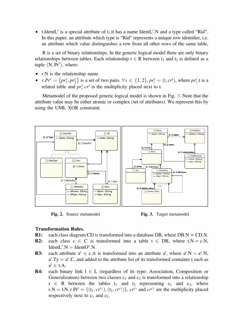
Class diagram metamodel is shown in Fig. 2; this metamodel is adapted from the
one proposed by the OMG [12].
Target. The target of UMLtoGenericModel transformation corresponds to a generic
logical model that describes data according to the common features of the three types of
NoSQL systems: column-oriented, document-oriented and graph-oriented. In the
generic logical model, a DataBase (DB) is defined as a tuple (N, T, R), where:
N is the database name,
T is a set of tables. The schema of each table t 2 T is a tuple ðN,A,IdentLtÞ), where:
• t.N is the table name,
• t.A ¼ at1; . . .; atq
n o
is a set of q attributes that will be used to define rows of t; each
row can have a variable number of attributes. The schema of each attribute at 2 A
is a pair (N,Ty) where “at.N” is the attribute name and “at.Ty” the attribute type.
• t.IdentLt is a special attribute of t; it has a name IdentLt.N and a type called “Rid”.
In this paper, an attribute which type is “Rid” represents a unique row identifier, i.e.
an attribute which value distinguishes a row from all other rows of the same table,
R is a set of binary relationships. In the generic logical model there are only binary
relationships between tables. Each relationship r 2 R between t1 and t2 is defined as a
tuple ðN; PrrÞ, where:
• r.N is the relationship name.
• r.Prr ¼ prr1; prr2
� �
is a set of two pairs. 8 i 2 1; 2f g, prri ¼ ðt; crtÞ, where prri .t is a
related table and prri .crt is the multiplicity placed next to t.
Metamodel of the proposed generic logical model is shown in Fig. 3. Note that the
attribute value may be either atomic or complex (set of attributes). We represent this by
using the UML XOR constraint.
Transformation Rules.
R1: each class diagram CD is transformed into a database DB, where DB.N = CD.N.
R2: each class c 2 C is transformed into a table t 2 DB, where t.N = c.N,
IdentLt.N ¼ IdentOc.N:
R3: each attribute ac 2 c.A is transformed into an attribute at, where at.N ¼ ac.N,
at.Ty ¼ ac.C, and added to the attribute list of its transformed container t such as
at 2 t.A.
R4: each binary link l 2 L (regardless of its type: Association, Composition or
Generalization) between two classes c1 and c2 is transformed into a relationship
r 2 R between the tables t1 and t2 representing c1 and c2, where
r.N ¼ l.N; r:Prr ¼ fðt1; crc1Þ; ðt2; cr
c2Þg, crc1 and crc2 are the multiplicity placed
respectively next to c1 and c2.
Fig. 2. Source metamodel
{XOR}
Fig. 3. Target metamodel
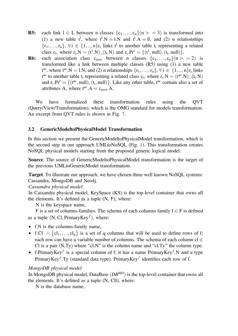
R5: each link l 2 L between n classes c1; . . .; cnf g n[ ¼ 3ð Þ is transformed into
(1) a new table tl, where tl:N ¼ l.N and tl:A ¼ ;, and (2) n relationships
r1; . . .; rnf g, 8 i 2 1; ::; nf gri links tl to another table ti representing a related
class ci, where ri.N ¼ ðt1.NÞ ðti.NÞ and ri:Prr ¼ fðt1; nullÞ; ðti; nullÞg.
R6: each association class casso between n classes c1; . . .; cnf g n[ ¼ 2ð Þ is
transformed like a link between multiple classes (R5) using (1) a new table
tac, where tac.N ¼ l.N, and (2) n relationships r1; . . .; rnf g, 8 i 2 1; ::; nf gri linkstac to another table ti representing a related class ci, where ri:N ¼ ðtac:NÞ ðti:NÞand ri:Pr
r ¼ fðtac; nullÞ; ðti; nullÞg. Like any other table, tac contain also a set of
attributes A, where tac:A ¼ casso:A.
We have formalized these transformation rules using the QVT
(Query/View/Transformation), which is the OMG standard for models transformation.
An excerpt from QVT rules is shown in Fig. 7.
3.2 GenericModeltoPhysicalModel Transformation
In this section we present the GenericModeltoPhysicalModel transformation, which is
the second step in our approach UMLtoNoSQL (Fig. 1). This transformation creates
NoSQL physical models starting from the proposed generic logical model.
Source. The source of GenericModeltoPhysicalModel transformation is the target of
the previous UMLtoGenericModel transformation.
Target. To illustrate our approach, we have chosen three well known NoSQL systems:
Cassandra, MongoDB and Neo4j.
Cassandra physical model
In Cassandra physical model, KeySpace (KS) is the top-level container that owns all
the elements. It’s defined as a tuple (N, F), where:
N is the keyspace name,
F is a set of columns-families. The schema of each columns family f 2 F is defined
as a tuple ðN;Cl; PrimaryKey f Þ, where:
• f.N is the columns-family name,
• f:Cl ¼ cl1; . . .; clq� �
is a set of q columns that will be used to define rows of f;
each row can have a variable number of columns. The schema of each column cl 2Cl is a pair (N,Ty) where “cl.N” is the column name and “cl.Ty” the column type.
• f.PrimaryKey f is a special column of f; it has a name PrimaryKey f .N and a type
PrimaryKey f .Ty (standard data type). PrimaryKey f identifies each row of f.
MongoDB physical model
In MongoDB physical model, DataBase DBMDð Þ is the top-level container that owns allthe elements. It’s defined as a tuple (N, Cll), where:
N is the database name,

Cll is a set of collections. The schema of each collection cll 2 Cll is a tuple
ðN; Fl; IdcllÞ, where:
• cll.N is the collection name,
• cll:Fl ¼ FlA [ FlCX sis a set of atomic and complex fields that will be used to define
rows, called documents, of Cll. Each document can have a variable number of
fields. The schema of an atomic field fla 2 FlA is a tuple (N,Ty) where “fla:N” is
the field name and “fla:Ty” is the field type. The schema of a complex field flcx 2FlCX is also a tuple (N, Fl’) where flcx N is the field name and flcx:F1’ is a set of
fields where Fl’� Fl.
• cll:Idcll is a special field of cll; it has a name Idcll:N and a type Idcll:Ty (standard data
type).Idcll identifies each document of cll.
Neo4j physical model
In Neo4j physical model, Graph (GR) is the top-level container that owns all the
elements. It’s defined as a tuple (V, E), where:
V is a set of vertex. The schema of each vertex v 2 V is a tuple ðL; Pro; IdvÞ, where:
• v.L is the vertex label,
• v:Pro ¼ pro1; . . .; proq� �
is a set of q properties. The schema of each property pro
2 Pro is a pair (N,Ty), where “pro.N” is the property name and “pro.Ty” the
property type.
• v:Idv is a special property of v; it has a name Idv:N, a type Idv:Ty and the constraint
“Is Unique”. It identifies uniquely v in the graph.
E is a set of edges. The schema of each edge e 2 E is a tuple ðL; v1; v2Þ, where:
• e.L is the edge label,
• e:v1 and e:v2 are the vertexes related by e.
Transformation Rules
For some NoSQL systems, many solutions can ensure the implementation of the
generic logical model. In order to choose the most suitable solution, the developer can
be well guided thanks to the performance measurement shown in Sect. 4.2. These
measurements concern the response time of queries that access two related tables; the
relationship between these tables has being implemented according to the different
solutions shown below. The developer will make his choice according to the queries
features he needs to perform as well as the expected performances.
We note that the set of solutions proposed in this section is not inclusive; more
marginal solutions may be considered.
To Cassandra physical model
R1: each database DB is transformed into a keyspace KS, where KS.N = DB.N.
R2: each table t 2 DB is transformed into a columns-family f 2 KS, where
f:N ¼ t:N;PrimaryKey f:N ¼ IdentLt
:N.
R3: each attribute at 2 t:A is transformed into a column cl, where
cl:N ¼ at:N; cl:Ty ¼ at:Ty, and added to the column list of its transformed
container f such as cl 2 f:Cl.

R4: As Cassandra does not support imbrication; the only solution we can use to
express relationships between columns-families consists in using reference
columns. A reference column is a monovalued or multivalued column in one
columns-family whose values must have matching values in the primary key of
another columns-family; we note that this constraint is not automatically managed
by the system Cassandra; it remains the responsibility of the user to check it.
For each relationship r between two tables t1 and t2, three solutions could be
considered:
Solution 1: r is transformed into a reference column cl referencing f2 (the
columns-family representing t2), where cl:N ¼ ðf2:NÞ _Ref and
cl:Ty ¼ PrimaryKeyf 2:Ty, and then added to the columns list of f1(the columns-family representing t1) such as cl 2 f1:Cl. While instan-
tiating f1, the value of the reference column cl will correspond to one or
many values in the primary key of f2.
Solution 2: r is transformed into a reference column cl referencing f1 (the
columns-family representing t1), where cl:N ¼ ðf1:NÞ _Ref
et cl:Ty ¼ PrimaryKeyf 1:Ty, and then added to the columns list of f2(the columns-family representing t2) such as cl 2 f2:Cl While instan-
tiating f2, the value of the reference column cl will correspond to one or
many values in the primary key of f1.
Solution 3: r is transformed into a new columns-family f composed of two reference
columns referencing the columns-families f1 and f2 representing the
related tables t1 and t2, where f.N = r.N, f:Cl ¼ cl1; cl2f g, cl1:N ¼
ðf1:NÞ _Ref, cl1:Ty ¼ PrimaryKeyf1:Ty; cl2:N ¼ ðf2:NÞ _Ref and
cl2:Ty ¼ PrimaryKeyf2:Ty.
A reference column can either be monovalued or multivalued. Table 1 indicates the
type of the reference column according to the relationship cardinalities and the trans-
formation solution used.
Table 1. Descriptive table of reference column types
Relationship Solution Reference column type
r ¼ ðN; fðt1; �Þ; ðt2; 1ÞgÞ Solution 1 Monovalued
Solution 2 Multivalued
Solution 3 Monovalued
r ¼ ðN; fðt1; 1Þ; ðt2; 1ÞgÞ Solution 1 Monovalued
Solution 2 Monovalued
Solution 3 Monovalued
r ¼ ðN; fðt1; �Þ; ðt2; �ÞgÞ Solution 1 Multivalued
Solution 2 Multivalued
Solution 3 Monovalued

To MongoDB physical model
R1: each database DB is transformed into a MongoDB database DBMD, where
DBMD.N = DB.N.
R2: each table t 2 DB is transformed into a collection cll 2 DBMD, where
cll:N ¼ t:Net Idcll:N ¼ IdentLt:N.
R3: each attribute at 2 t.A is transformed into an atomic field fla, where
fla.N ¼ at:N, fla:Ty ¼ at.Ty, and added to the field list of its transformed
container cll such as fl 2 cll:FlA.
R4: relationships in MongoDB could be transformed by using reference fields or
embedding. A reference field is a monovalued or multivalued field in one
collection whose values must have matching values in the Id of another
collection; checking this constraint remains the responsibility of the user.
For each relationship r between two tables t1 and t2, five solutions could be
considered:
Solution 1: r is transformed into a reference field fl referencing cll2 (the collection
representing t2), where fl:N ¼ ðcll2:NÞ _Ref and fl:Ty ¼ Idcll2 :Ty, and
then added to the fields list of cll1 (the collection representing t1) such as
fl 2 cll1:FlA.
Solution 2: r is transformed into a reference field fl referencing cll1 (the collection
representing t1), where fl:N ¼ ðcll1:NÞ _Ref and fl:Ty ¼ Idcll1 :Ty, and
added to the field list of cll2 (the collection representing t2) such as
fl 2 cll2:FlA.
Solution 3: r is transformed by embedding the collection cll2 representing t2 in the
collection cll1 representing t1, where cll2 2 cll1:FlCX .
Solution 4: r is transformed by embedding the collection cll1 representing t1 in the
collection cll2 representing t2, where cll1 2 cll2:FlCX .
Solution 5: r is transformed into a new collection cll, where cll.N = r.N,
cll:Fl ¼ fl1; fl2f g, fl1:N ¼ ðcll1:NÞ _Ref, fl1:Ty ¼ Idcll2 :Ty, fl2:N ¼
ðcll2:NÞ _Ref and fl2:Ty ¼ Idcll2 :Ty, where cll1 and cll2 are the
collections representing t1 and t2.
Each reference field used in Solution 1, 2 and 5 can either be monovalued or
multivalued. Table 2 indicates the type of the reference field according to the rela-
tionship cardinalities and the transformation solution used.
To Neo4j physical model
R1: each table t 2 DB is transformed into a vertex v 2 V, where v.L = t.N,
Idv:N ¼ IdentLt:N.

R2: each attribute at 2 t.A is transformed into a property pro, where pro:N ¼ at:N,
pro:Ty ¼ at.Ty, and added to the property list of its transformed container v
such as pro 2 v:Pro.
R3: Each relationship r between two tables t1 and t2 is transformed into an edge e,
where e.L = r.N, relating two vertex v1 and v2, where v1 and v2 are the vertex
representing t1 and t2.
4 Experiments
In this section, we show how to transform a UML conceptual model into NoSQL
physical models. As presented in Sect. 3.2, several solutions can ensure this trans-
formation; we therefore began by implementing the UMLtoNoSQL process according
to each proposed solution, and then we evaluated their performances to assist the
developer in choosing the most effective one.
4.1 Implementation
Experimental environment. We carry out the experimental assessment using a model
transformation environment called Eclipse Modeling Framework (EMF). It’s a set of
plugins which can be used to create a model and to generate other output based on this
model. Among the tools provided by EMF we use: (1) Ecore: the metamodeling
language that we used to create our metamodels. (2) XML Metadata Interchange
(XMI): the XML based standard that we use to create models. (3) Query/View /
Transformation (QVT): the OMG language for specifying model transformations.
Implementation of UMLtoGenericModel Transformation. UMLtoGenericModel
transformation is expressed as a sequence of elementary steps that builds the resulting
model (generic logical model) step by step from the source model (UML class
diagram):
Table 2. Descriptive table of reference field types
Relationship Solution Reference field type
r ¼ ðN; fðt1; �Þ; ðt2; 1ÞgÞ Solution 1 Monovalued
Solution 2 Multivalued
Solution 5 Monovalued
r ¼ ðN; fðt1; 1Þ; ðt2; 1ÞgÞ Solution 1 Monovalued
Solution 2 Monovalued
Solution 5 Monovalued
r ¼ ðN; fðt1; �Þ; ðt2; �ÞgÞ Solution 1 Multivalued
Solution 2 Multivalued
Solution 5 Monovalued

Step 1: we create Ecore metamodels corresponding to the source (Fig. 2) and the
target (Fig. 3).
Step 2: we build an instance of the source metamodel. For this, we use the
standard-based XML Metadata Interchange (XMI) format (Fig. 4).
Step 3: we implement the transformation rules by means of the QVT plugin pro-
vided within EMF. An excerpt from the QVT script is shown in Fig. 7; the
comments in the script indicate the rules used.
Step 4: we test the transformation by running the QVT script created in step 3. This
script takes as input the source model builded in step 2 and returns as output
the logical model. The result is provided in the form of XMI file as shown in
Fig. 5.
Implementation of GenericModeltoPhysicalModel Transformation. The generic
logical model that we proposed in this paper does not imply a specific system; it
exhibits a sufficient degree of independence so as to enable its mapping to different
NoSQL platforms. For some NoSQL systems, relationships could be transformed into
several forms (monovalued or multivalued references, embedding). Lacks of place, we
only present one implementation of the generic logical model that was performed on
Cassandra according to Solution 1. Figure 8 shows the corresponding QVT script. This
script takes as input the logical model (Fig. 5) generated by the previous transformation
and return as output Cassandra physical model (Fig. 6).
Fig. 4. Source model Fig. 5. Target model Fig. 6. Cassandra model

4.2 Evaluation
The graph-oriented system Neo4j does not offer many solutions to implement rela-
tionships; therefore, the developer does not need to choose between several solutions.
For Cassandra and MongoDB, where many choices are available, we have evaluated
the transformation solutions proposed in Sect. 3.2. This evaluation aims at studying the
impact that the choice of the used solution may have on the queries execution time.
Experimental environment. The experiments are done on a cluster made up of 3
machines. Each machine has the following specifications: Intel Core i5, 8 GB RAM
and 2 TB disk.
Data set. In order to perform our experiments, we have used data generator tools. We
have generated a dataset of about 1 TB with CSV format for Cassandra and JSON
format for MongoDB. These files are loaded into the systems using shell commands.
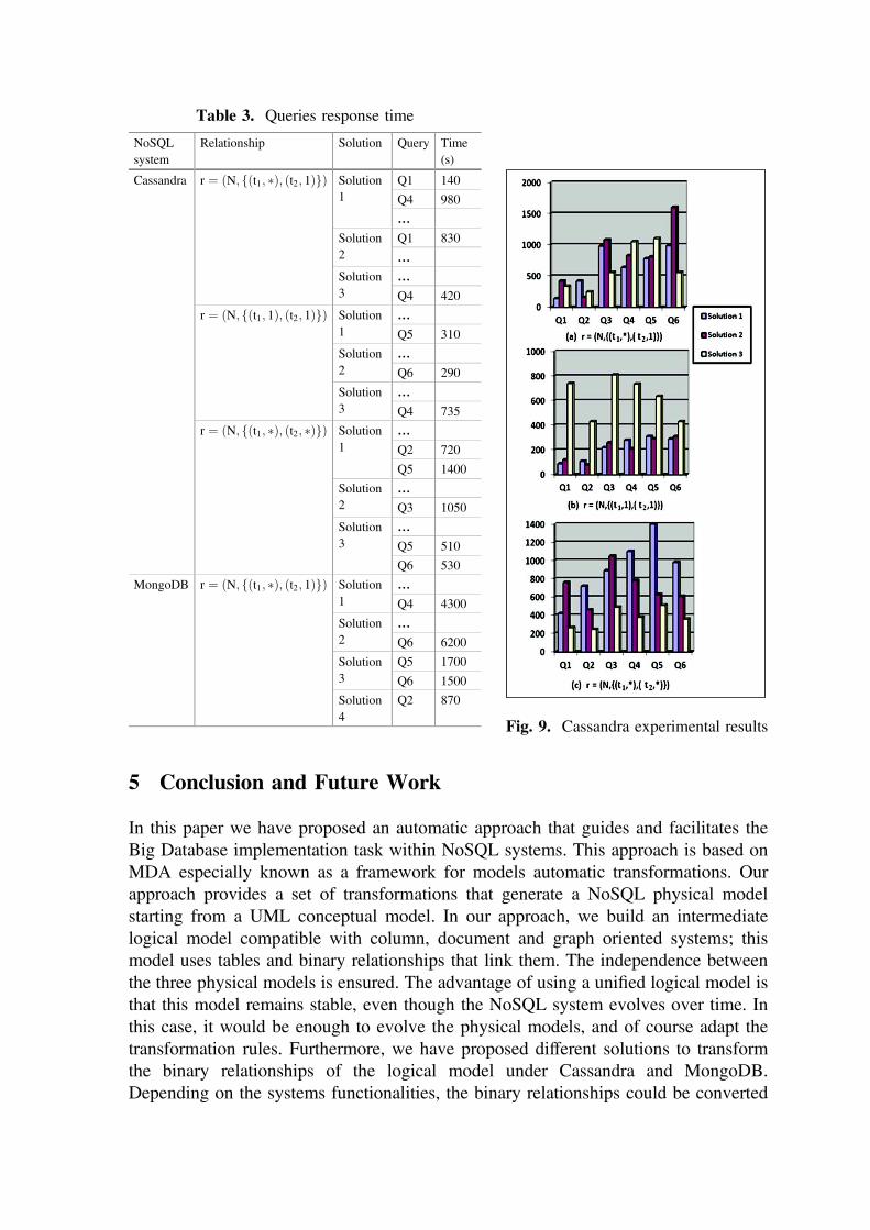
Queries set. For our experiments, we have written 6 queries; each query concerns two
tables and the relationship between them. The complexity of these queries increases
gradually. The simplest one applies a filter to a table and returns attributes of the other
table; the most complex one applies several filters and returns attributes of the two
related tables. We note that the concepts “table” and “attribute” correspond respectively
to “columns-family” and “column” in Cassandra or “collection” and “field” in Mon-
goDB. An excerpt from our experiment results is depicted in Table 3 and Figs. 9(a),
(b) and (c). For each query, we indicate the response time obtained according to (1) the
relationship cardinalities and (2) the solution used.
modeltype UML uses "http://UMLClassDiagram.com";modeltype COLM uses "http://GenericLogicalModel.com";transformationTransformationUmlToColumnsOrientedModel(in Source:UML, out Target: COLM);main() {Source.rootObjects()[ClassDiagram] -> map toDataBase();}-- Transforming Class Diagram to DataBasemapping ClassDiagram::toDataBase():DataBase{name := self.name;table:=self.classes -> maptoClass();relationship:=self.links -> toRelationship();}-- Transforming Class to Tablemapping UML::Class::toClass():COLM::Table{name:=self.name;attributet:=self.attributec -> map toAttribute();}-- Transforming Attribute to Columnmapping UML::Attribute::toAttribute():COLM::Attribute{name:=self.name;typea:=self.typea -> map toType(); }mapping UML::Type::toType():COLM::Type{typea:=self.typea;}mapping UML::Link::toRelationship():COLM::RelationShip{name:=self.name; linkedtable:=self.linkedclass -> map toLinkedTable();
Fig. 7. UMLtoGenericModel
TransformationTransformationGenericModelToCassandraModel(in Source: LogicalPIM, out Target:CassandraPSM);main() {Source.rootObjects()[DataBase] -> map toKeySpace();}-- Transforming DataBase to KeySpacemapping DataBase::toKeySpace():KeySpace{name := self.name;columnsfamily:=self.table ->map toColumnsFamily();} -- Transforming Table to Columns-Familymapping LogicalPIM ::Table::toColumnsFamily():CassandraPSM::ColumnsFamily{name:=self.name;column:=self.attributet -> map toColumn();referencecolumn:=self.islinkedto ->map toReferenceColumn();} mapping LogicalPIM ::Type::toType():CassandraPSM::Type{if(self.typea = "Rid"){type:='Int';}endif;type:=self.typea;}-- Transforming (1,*) RelationShip to a Monovalued Refmapping LogicalPIM ::LinkedToTable::toReferenceColumn():CassandraPSM ::ReferenceColumn{if(self.cardinalityoftable = "*" andself.cardinalityoflinkedtable
Fig. 8. GenericModeltoCassandraModel
5 Conclusion and Future Work
In this paper we have proposed an automatic approach that guides and facilitates the
Big Database implementation task within NoSQL systems. This approach is based on
MDA especially known as a framework for models automatic transformations. Our
approach provides a set of transformations that generate a NoSQL physical model
starting from a UML conceptual model. In our approach, we build an intermediate
logical model compatible with column, document and graph oriented systems; this
model uses tables and binary relationships that link them. The independence between
the three physical models is ensured. The advantage of using a unified logical model is
that this model remains stable, even though the NoSQL system evolves over time. In
this case, it would be enough to evolve the physical models, and of course adapt the
transformation rules. Furthermore, we have proposed different solutions to transform
the binary relationships of the logical model under Cassandra and MongoDB.
Depending on the systems functionalities, the binary relationships could be converted
Table 3. Queries response time
NoSQL
system
Relationship Solution Query Time
(s)
Cassandra r ¼ ðN; fðt1; �Þ; ðt2; 1ÞgÞ Solution
1
Q1 140
Q4 980
…
Solution
2
Q1 830
…
Solution
3
…
Q4 420
r ¼ ðN; fðt1; 1Þ; ðt2; 1ÞgÞ Solution
1
…
Q5 310
Solution
2
…
Q6 290
Solution
3
…
Q4 735
r ¼ ðN; fðt1; �Þ; ðt2; �ÞgÞ Solution
1
…
Q2 720
Q5 1400
Solution
2
…
Q3 1050
Solution
3
…
Q5 510
Q6 530
MongoDB r ¼ ðN; fðt1; �Þ; ðt2; 1ÞgÞ Solution
1
…
Q4 4300
Solution
2
…
Q6 6200
Solution
3
Q5 1700
Q6 1500
Solution
4
Q2 870
Fig. 9. Cassandra experimental results

into different forms. We have measured the queries response time using each of the
proposed solution. The developer can choose the most suited solution according to:
(1) Queries features (number of filters, number of attributes to return, etc.), (2) The time
response and (3) Query frequency of use.
As future work, we plan to complete our transformation process in order to take
into account the constraints of the conceptual level and to preserve the semantics of
links when transforming the conceptual model to the logical one. Furthermore, we want
to define the transformations rules of physical models into NoSQL scripts using
model-to-text transformation (M2T).
References
1. Angadi, A., Angadi, A., Gull, K.: Growth of new databases and analysis of NOSQL
datastores. In: IJARCSSE (2013)
2. Cattell, R.: Scalable SQL and NoSQL data stores. ACM SIGMOD Rec. 39(4), 12–27 (2011)
3. Abello, A.: Big data design. In: DOLAP (2015)
4. Hutchinson, J., Rouncefield, M.: Model-driven engineering practices in industry. In: ICSE
(2011)
5. Li, C.: Transforming relational database into HBase: A case study. In: ICSESS (2010)
6. Vajk, T., Feher, P., Fekete, K., Charaf, H.: Denormalizing data into schema-free databases.
In: CogInfoCom (2013)
7. Daniel, G., Sunyé, G., Cabot, J.: UMLtoGraphDB: Mapping conceptual schemas to graph
databases. In: Comyn-Wattiau, I., Tanaka, K., Song, I.-Y., Yamamoto, S., Saeki, M. (eds.)
ER 2016. LNCS, vol. 9974, pp. 430–444. Springer, Cham (2016). doi:10.1007/978-3-319-
46397-1_33
8. Bézivin, J., Gerbé, O.: Towards a precise definition of the OMG/MDA framework. In: ASE
(2001)
9. Chevalier, M., El Malki, M., Kopliku, A., Teste, O., Tournier, R.: Implementing
multidimensional data warehouses into NoSQL. In: ICEIS (2015)
10. Abadi, D., Madden, S., Hachem, N.: Column-stores vs. row-stores: how different are they
really?. In: COMAD (2008)
11. Li, Y., Gu, P., Zhang, C.: Transforming UML class diagrams into HBase based on
meta-model. In: ISEEE (2014)
12. http://www.omg.org/spec/UML/2.5/
13. http://www.gartner.com/smarterwithgartner/gartners-top-10-technology-trends-2017/
14. Herrero, V., Abelló, A., Romero, O.: NOSQL design for analytical workloads: variability
matters. In: Comyn-Wattiau, I., Tanaka, K., Song, I.-Y., Yamamoto, S., Saeki, M. (eds.) ER
2016. LNCS, vol. 9974, pp. 50–64. Springer, Cham (2016). doi:10.1007/978-3-319-46397-
1_4
15. Dehdouh, K., Bentayeb, F., Boussaid, O., Kabachi, N.: Using the column oriented model for
implementing big data warehouses. In: PDPTA (2015)
Related Documents