MCS: 029 Micro-Cogeneration Add-On-Test Package: Test methodology based on PAS 67:2013 Issue 1.0

Welcome message from author
This document is posted to help you gain knowledge. Please leave a comment to let me know what you think about it! Share it to your friends and learn new things together.
Transcript

MCS: 029
Micro-Cogeneration Add-On-Test Package:
Test methodology based on PAS 67:2013
Issue 1.0
2 Micro-Cogeneration Add-On-Test Package: Test methodology based on PAS 67:2013 Version: v1.0
Micro-Cogeneration Add-On-Test Package: Test methodology based on PAS 67:2013 Version: v1.0
1 Table of Contents
1. INTRODUCTION 3
2. PAS 67:2013 STANDARD - OVERVIEW 4
2.1. MICRO-COGENERATION PACKAGE CATEGORIES ........................................................................................................................................................................... 4
2.2. THE OPERATING TEST MODES COVERED BY THE STANDARD .......................................................................................................................................... 4
2.3. MAIN PARAMETERS MEASURED DURING PERFORMANCE TESTING OF MCP................................................................................................................... 4
2.4. PAS 67: 2013 TEST RESULTS AND APPLICATIONS ........................................................................................................................................................................ 5
2.4.1. SINGLE-FAMILY DWELLINGS ........................................................................................................................................................................................................................ 5
2.4.2. COMMERCIAL AND MULTI-FAMILY DWELLINGS ............................................................................................................................................................................... 6
2.5. PERFORMANCE RESULTS OF A HYPOTHETICAL INTEGRATED MCP ..................................................................................................................................... 6
3. ADD-ON MICRO-COGENERATION PACKAGE AND TEST PROCEDURE 8
3.1. DESCRIPTION ................................................................................................................................................................................................................................................ 8
3.1.1. ADD-ON MCP FOR SPACE AND HOT WATER HEATING .................................................................................................................................................................... 8
3.1.2. ADD-ON MCP FOR SPACE HEATING ONLY .............................................................................................................................................................................................. 9
3.1.3. ADD-ON MCP FOR HOT WATER (DHW) HEATING ONLY .............................................................................................................................................................. 10
3.2. PROPOSED PAS 67:2013 TEST METHOD FOR ADD-ON MCP .................................................................................................................................................. 11
3.2.1. KEY REQUIREMENTS OF TEST METHODOLOGY ............................................................................................................................................................................... 11
3.2.2. PRIME MOVER AND SUPPLEMENTARY HEAT SOURCE INTEGRATION ................................................................................................................................. 12
3.2.3. TEST METHODOLOGY FOR THE ADD-ON MCP/MCU - GENERAL .............................................................................................................................................. 12
3.2.4. DHW TESTS FOR THE ADD-ON MCP/MCU ........................................................................................................................................................................................... 14
3.2.5. SPACE HEATING TESTS FOR THE ADD-ON MCP/MCU ................................................................................................................................................................... 14
3.3. PERFORMANCE AND SPECIFICATION OF THE EXAMPLE ADD-ON MCP ........................................................................................................................... 14
4. MICRO-COGENERATION ADD-ON CALCULATOR 16
4.1. OVERVIEW ................................................................................................................................................................................................................................................... 16
4.2. DESCRIPTION ............................................................................................................................................................................................................................................. 17
4.2.1. TAB: “Manufacturer’s Declaration” .......................................................................................................................................................................................................... 17
4.2.2. TAB / SHEET ‘Reference Test Data’ .......................................................................................................................................................................................................... 19
4.2.3. TAB/SHEET ‘Installation Package’ ........................................................................................................................................................................................................... 21
4.2.4. TAB / SHEET ‘REF_DATA’ .............................................................................................................................................................................................................................. 23
5. Appendix 1: Performance specification of the example Add-on MCP 24
6. APPENDIX 2: MICRO-COGENERATION ADD-ON CALCULATOR PROCEDURES (ALGORITHMS) 25
6.1. STANDBY PERFORMANCE CALCULATIONS ................................................................................................................................................................................... 25
6.1.1. ASSUMPTIONS ..................................................................................................................................................................................................................................................... 25
6.1.2. CALCULATION PROCEDURE ......................................................................................................................................................................................................................... 25
6.2. DHW HEATING PERFORMANCE CALCULATIONS ........................................................................................................................................................................ 25
6.2.1. ASSUMPTIONS ..................................................................................................................................................................................................................................................... 25
6.2.2. CALCULATION PROCEDURES ...................................................................................................................................................................................................................... 25
6.3. SPACE HEATING PERFORMANCE CALCULATIONS ..................................................................................................................................................................... 28
6.3.1. ASSUMPTIONS ..................................................................................................................................................................................................................................................... 28
6.3.2. CALCULATION PROCEDURES ...................................................................................................................................................................................................................... 28

3 Micro-Cogeneration Add-On-Test Package: Test methodology based on PAS 67:2013 Version: v1.0
Micro-Cogeneration Add-On-Test Package: Test methodology based on PAS 67:2013 Version: v1.0
1. INTRODUCTION The current PAS 67:2013 specifies the laboratory tests to determine the heating and electrical performance of heat-led micro-cogeneration
packages primarily intended for heating dwellings. However it does not cover testing of micro-cogeneration unit (MCU) or add-on package (MCP)
incorporating a micro-cogeneration unit designed for integrating with the existing heating or hot water systems in buildings.
This document described the test methodology and the application of test data for installing the Add-on micro-cogeneration unit or package.
The testing of the Add-on MCP/MCU is based on established procedures defined in PAS67: 2013 with additional measurements to quantify the
performance of the Add-on package when it is tested with the reference heat source. The test results are normalised using the Micro-
Cogeneration Add-On Calculator for generating installation performance data e.g. by using the APM calculator or SBEM for non-domestic
buildings.
A hypothetical Add-on MCP was used to test and validate the proposed test and application procedures. The performance of tis example Add-on
MCP was modelled as an integrated unit including the supplementary boiler. The data was then transferred to the APM calculator to calculate
base level results (Section 2.5) for comparison. The example was then modelled as an Add-on MCP with 30kW reference test boiler and
performance results were calculated and compared with an integrated MCP variant example (Sections 3 & 4).
The comparison of the current certification and application procedures for the integrated MCP and the proposed procedure for the Add-on
Micro-cogeneration unit/package are shown in figure 1.1. As shown in this figure, the certification and the application procedures for both Add-
on MCP and an integrated MCP are similar. The Micro-Cogeneration Add-On Calculator also compares the CO2 emissions of the Add-On MCP
heating system with equivalent conventional gas heating system at the reference space and hot water heating test condition.
Integrated MCP
Performance testing to PAS 67:2013
Performance test results
APM Calculator
Product Characteristics
Database
Building & System performance assessment SAP 2103, or SBEM Energy models
Installers, Designers etc.
Test house
Add-On MCU/MCP
Performance testing to PAS 67:2013
with reference boiler when specified Including additional measurements
Performance test results
APM Calculator
APM Results
Test house
Add-on MCP/MCU calculator
MIS 3007, MIS 3007-2 MCS 014, MCS 015
MANUFACTURER
Product literatures etc. APM Results
Add-on MCP/MCU calculator results
for different boiler & system sizes
MIS 3007, MIS 3007-2 MCS 014, MCS 015
Single family
Dwellings Commercial
Buildings etc.
Single family
Dwellings
Building & System performance assessment SAP 2103, or SBEM Energy models
Product
Characteristics Database
Commercial Buildings etc.
Figure 1.1 (v21042016)
4 Micro-Cogeneration Add-On-Test Package: Test methodology based on PAS 67:2013 Version: v1.0
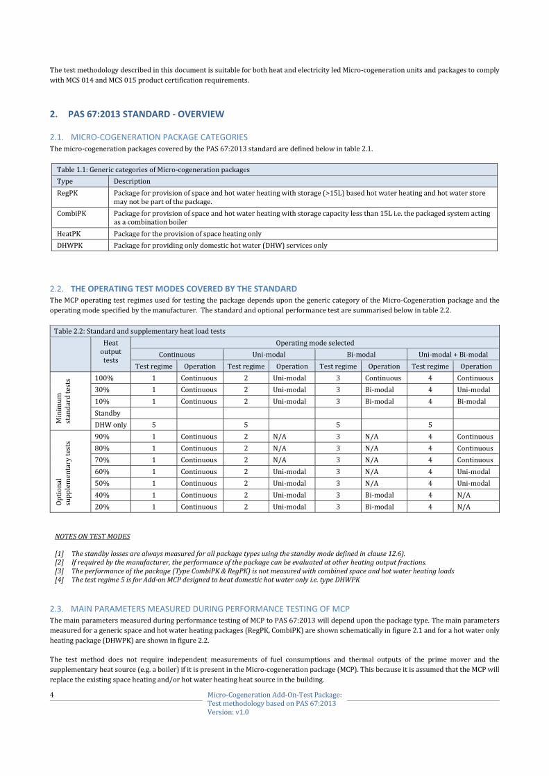
The test methodology described in this document is suitable for both heat and electricity led Micro-cogeneration units and packages to comply
with MCS 014 and MCS 015 product certification requirements.
2. PAS 67:2013 STANDARD - OVERVIEW
2.1. MICRO-COGENERATION PACKAGE CATEGORIES The micro-cogeneration packages covered by the PAS 67:2013 standard are defined below in table 2.1.
Table 1.1: Generic categories of Micro-cogeneration packages
Type Description
RegPK Package for provision of space and hot water heating with storage (>15L) based hot water heating and hot water store may not be part of the package.
CombiPK Package for provision of space and hot water heating with storage capacity less than 15L i.e. the packaged system acting as a combination boiler
HeatPK Package for the provision of space heating only
DHWPK Package for providing only domestic hot water (DHW) services only
2.2. THE OPERATING TEST MODES COVERED BY THE STANDARD The MCP operating test regimes used for testing the package depends upon the generic category of the Micro-Cogeneration package and the
operating mode specified by the manufacturer. The standard and optional performance test are summarised below in table 2.2.
Table 2.2: Standard and supplementary heat load tests
Heat output tests
Operating mode selected
Continuous Uni-modal Bi-modal Uni-modal + Bi-modal
Test regime Operation Test regime Operation Test regime Operation Test regime Operation
Min
imu
m
stan
dar
d t
ests
100% 1 Continuous 2 Uni-modal 3 Continuous 4 Continuous
30% 1 Continuous 2 Uni-modal 3 Bi-modal 4 Uni-modal
10% 1 Continuous 2 Uni-modal 3 Bi-modal 4 Bi-modal
Standby
DHW only 5 5 5 5
Op
tio
nal
su
pp
lem
enta
ry t
ests
90% 1 Continuous 2 N/A 3 N/A 4 Continuous
80% 1 Continuous 2 N/A 3 N/A 4 Continuous
70% 1 Continuous 2 N/A 3 N/A 4 Continuous
60% 1 Continuous 2 Uni-modal 3 N/A 4 Uni-modal
50% 1 Continuous 2 Uni-modal 3 N/A 4 Uni-modal
40% 1 Continuous 2 Uni-modal 3 Bi-modal 4 N/A
20% 1 Continuous 2 Uni-modal 3 Bi-modal 4 N/A
NOTES ON TEST MODES [1] The standby losses are always measured for all package types using the standby mode defined in clause 12.6). [2] If required by the manufacturer, the performance of the package can be evaluated at other heating output fractions. [3] The performance of the package (Type CombiPK & RegPK) is not measured with combined space and hot water heating loads [4] The test regime 5 is for Add-on MCP designed to heat domestic hot water only i.e. type DHWPK
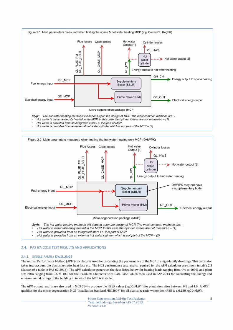
2.3. MAIN PARAMETERS MEASURED DURING PERFORMANCE TESTING OF MCP The main parameters measured during performance testing of MCP to PAS 67:2013 will depend upon the package type. The main parameters
measured for a generic space and hot water heating packages (RegPK, CombiPK) are shown schematically in figure 2.1 and for a hot water only
heating package (DHWPK) are shown in figure 2.2.
The test method does not require independent measurements of fuel consumptions and thermal outputs of the prime mover and the
supplementary heat source (e.g. a boiler) if it is present in the Micro-cogeneration package (MCP). This because it is assumed that the MCP will
replace the existing space heating and/or hot water heating heat source in the building.
5 Micro-Cogeneration Add-On-Test Package: Test methodology based on PAS 67:2013 Version: v1.0
2.4. PAS 67: 2013 TEST RESULTS AND APPLICATIONS
2.4.1. SINGLE-FAMILY DWELLINGS
The Annual Performance Method (APM) calculator is used for calculating the performance of the MCP in single-family dwellings. This calculator
takes into account the plant size ratio, heat loss etc. The MCS performance test results required for the APM calculator are shown in table 2.3
(Subset of a table in PAS 67:2013). The APM calculator generates the data listed below for heating loads ranging from 0% to 100% and plant
size ratio ranging from 0.5 to 10.0 for the ‘Products Characteristics Data Base’ which then used in SAP 2013 for calculating the energy and
environmental ratings of the building in in which the MCP is installed.
The APM output results are also used in MCS 014 to produce the HPER values (kgCO2/kWh) for plant size ratios between 0.5 and 4.0. A MCP
qualifies for the micro-cogeneration MCS “Installation Standard MIS 3007” for all plant size ratio where the HPER is ≤ 0.230 kgCO2/kWh.
6 Micro-Cogeneration Add-On-Test Package: Test methodology based on PAS 67:2013 Version: v1.0
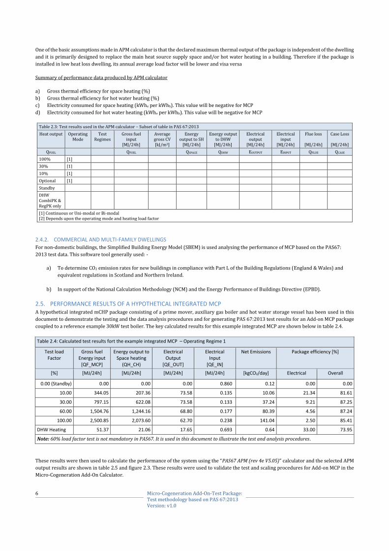
One of the basic assumptions made in APM calculator is that the declared maximum thermal output of the package is independent of the dwelling
and it is primarily designed to replace the main heat source supply space and/or hot water heating in a building. Therefore if the package is
installed in low heat loss dwelling, its annual average load factor will be lower and visa versa
Summary of performance data produced by APM calculator
a) Gross thermal efficiency for space heating (%)
b) Gross thermal efficiency for hot water heating (%)
c) Electricity consumed for space heating (kWhe per kWhh). This value will be negative for MCP
d) Electricity consumed for hot water heating (kWhe per kWhh). This value will be negative for MCP
Table 2.3: Test results used in the APM calculator – Subset of table in PAS 67:2013
Heat output Operating Mode
Test Regimes
Gross fuel input
[MJ/24h]
Average gross CV [kJ/m3]
Energy output to SH
[MJ/24h]
Energy output to DHW
[MJ/24h]
Electrical output
[MJ/24h]
Electrical input
[MJ/24h]
Flue loss
[MJ/24h]
Case Loss
[MJ/24h]
QFUEL QFUEL QSPACE QDHW EOUTPUT EINPUT QFLUE QCASE
100% [1]
30% [1]
10% [1]
Optional [1]
Standby
DHW CombiPK & RegPK only
[1] Continuous or Uni-modal or Bi-modal [2] Depends upon the operating mode and heating load factor
2.4.2. COMMERCIAL AND MULTI-FAMILY DWELLINGS
For non-domestic buildings, the Simplified Building Energy Model (SBEM) is used analysing the performance of MCP based on the PAS67:
2013 test data. This software tool generally used: -
a) To determine CO2 emission rates for new buildings in compliance with Part L of the Building Regulations (England & Wales) and
equivalent regulations in Scotland and Northern Ireland.
b) In support of the National Calculation Methodology (NCM) and the Energy Performance of Buildings Directive (EPBD).
2.5. PERFORMANCE RESULTS OF A HYPOTHETICAL INTEGRATED MCP A hypothetical integrated mCHP package consisting of a prime mover, auxiliary gas boiler and hot water storage vessel has been used in this
document to demonstrate the testing and the data analysis procedures and for generating PAS 67:2013 test results for an Add-on MCP package
coupled to a reference example 30kW test boiler. The key calculated results for this example integrated MCP are shown below in table 2.4.
Table 2.4: Calculated test results fort the example integrated MCP – Operating Regime 1
Test load Factor
Gross fuel Energy input
[QF_MCP]
Energy output to Space heating
(QH_CH)
Electrical Output
[QE_OUT]
Electrical Input
[QE_IN]
Net Emissions Package efficiency [%]
[%] [MJ/24h] [MJ/24h] [MJ/24h] [MJ/24h] [kgCO2/day] Electrical Overall
0.00 (Standby) 0.00 0.00 0.00 0.860 0.12 0.00 0.00
10.00 344.05 207.36 73.58 0.135 10.06 21.34 81.61
30.00 797.15 622.08 73.58 0.133 37.24 9.21 87.25
60.00 1,504.76 1,244.16 68.80 0.177 80.39 4.56 87.24
100.00 2,500.85 2,073.60 62.70 0.238 141.04 2.50 85.41
DHW Heating 51.37 21.06 17.65 0.693 0.64 33.00 73.95
Note: 60% load factor test is not mandatory in PAS67. It is used in this document to illustrate the test and analysis procedures.
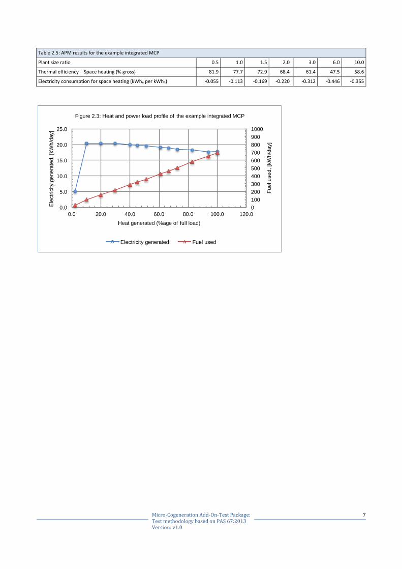
These results were then used to calculate the performance of the system using the “PAS67 APM (rev 4e V5.05)” calculator and the selected APM
output results are shown in table 2.5 and figure 2.3. These results were used to validate the test and scaling procedures for Add-on MCP in the
Micro-Cogeneration Add-On Calculator.
7 Micro-Cogeneration Add-On-Test Package: Test methodology based on PAS 67:2013 Version: v1.0
Table 2.5: APM results for the example integrated MCP
Plant size ratio 0.5 1.0 1.5 2.0 3.0 6.0 10.0
Thermal efficiency – Space heating (% gross) 81.9 77.7 72.9 68.4 61.4 47.5 58.6
Electricity consumption for space heating (kWhe per kWhh) -0.055 -0.113 -0.169 -0.220 -0.312 -0.446 -0.355
0
100
200
300
400
500
600
700
800
900
1000
0.0
5.0
10.0
15.0
20.0
25.0
0.0 20.0 40.0 60.0 80.0 100.0 120.0
Fu
el u
se
d,
[kW
h/d
ay]
Ele
ctr
icity g
en
era
ted
, [k
Wh
/day]
Heat generated (%age of full load)
Figure 2.3: Heat and power load profile of the example integrated MCP
Electricity generated Fuel used

8 Micro-Cogeneration Add-On-Test Package: Test methodology based on PAS 67:2013 Version: v1.0
3. ADD-ON MICRO-COGENERATION PACKAGE AND TEST PROCEDURE
3.1. DESCRIPTION The add-on micro-cogeneration Package i.e. “Add-on MCP” is primarily designed to integrate with the existing space and/or hot water heating
systems in a domestic and commercial buildings and to use the existing main heat source (e.g. a gas boiler) to supplement the heat produced by
the prime mover in the Add-on MCP if and when required. The main components of the Add-on MCP are listed below and typical examples of
test configurations for different types of Add-on MCP are described and shown in the following sections.
a) Prime mover mCHP appliance (e.g. Fuel Cell, ICE).
b) Control and hydraulic packages for integrating with existing system.
c) Domestic hot water cylinder or an integrated thermal store (If these are part of the part of the Add-on package).
d) Installation and operating instructions.
3.1.1. ADD-ON MCP FOR SPACE AND HOT WATER HEATING
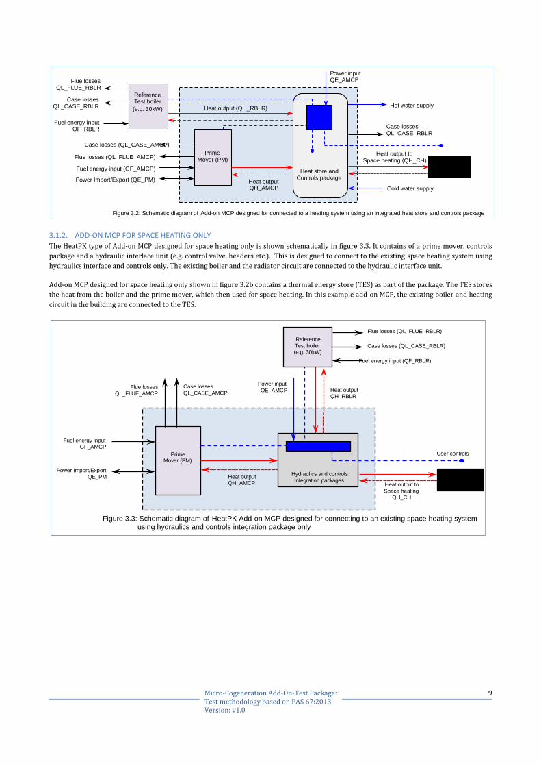
The schematic diagram of an Add-on MCP shown in figure 3.1 contains of a prime mover, controls package and a hydraulic interlace unit (e.g.
control valve, headers etc.). This is designed to connect to the existing heating and hot water system using hydraulics interface and controls
only. The existing boiler, radiator circuit and the hot water cylinder [1] are connected to the hydraulic interface unit. For the reference testing,
the manufacturer would specify the external hot water cylinder for the RegPK types of Add-on MCP, which is designed to provide both space
and hot water heating.
The hot water cylinder is not required for the CombiPK type of Add-on MCP because, the domestic hot water service is provided wholly from
within the package supplied for testing.
Add-on MCP type shown schematically in figure 3.2 contains a thermal energy store (TES) as part of the package. In this example the existing
boiler and heating circuit in the building are connected to the TES and it also provides domestic hot water. Therefore the existing hot water
cylinder in the building (if present) will normally be removed.
NOTES
[1] It is likely that the DHW only systems will be suitable for range of different external cylinder sizes. The cylinder size can influence the type of
tapping cycle that can be achieved with the combination of Add-On MCP and the external heat source. Therefore reference testing of the DHW
only Add-On MCP with the smallest recommended external cylinder should be considered.
Fuel energy input GF_AMCP
Flue losses QL_FLUE_AMCP
Case losses QL_CASE_AMCP
Prime Mover (PM)
Power Import/Export
QE_PM Heat output QH_AMCP Heat output to
Space heating QH_CH
Heat output to DHW heating
QH_DHW
Cold water Supply
Hot water Supply
HW Storage Vessel
Hydraulics and controls Integration packages
Heat output QH_RBLR
Power input QE_AMCP
Figure 3.1: Schematic diagram of Add-on MCP designed for connecting to an existing space and hot water heating system using hydraulics and controls integration package only
Flue losses (QL_FLUE_RBLR)
Reference Test boiler (e.g. 30kW)
Fuel energy input (QF_RBLR)
Case losses (QL_CASE_RBLR)
Case losses QL_CASE_WHS
9 Micro-Cogeneration Add-On-Test Package: Test methodology based on PAS 67:2013 Version: v1.0
3.1.2. ADD-ON MCP FOR SPACE HEATING ONLY
The HeatPK type of Add-on MCP designed for space heating only is shown schematically in figure 3.3. It contains of a prime mover, controls
package and a hydraulic interlace unit (e.g. control valve, headers etc.). This is designed to connect to the existing space heating system using
hydraulics interface and controls only. The existing boiler and the radiator circuit are connected to the hydraulic interface unit.
Add-on MCP designed for space heating only shown in figure 3.2b contains a thermal energy store (TES) as part of the package. The TES stores
the heat from the boiler and the prime mover, which then used for space heating. In this example add-on MCP, the existing boiler and heating
circuit in the building are connected to the TES.
Fuel energy input (GF_AMCP)
Flue losses QL_FLUE_RBLR
Flue losses (QL_FLUE_AMCP)
Case losses (QL_CASE_AMCP)
Prime Mover (PM)
Power Import/Export (QE_PM) Heat output QH_AMCP
Heat output to Space heating (QH_CH)
Cold water supply
Hot water supply
Reference Test boiler
(e.g. 30kW)
Fuel energy input QF_RBLR
Case losses QL_CASE_RBLR
Power input QE_AMCP
Figure 3.2: Schematic diagram of Add-on MCP designed for connected to a heating system using an integrated heat store and controls package
Heat store and Controls package
Heat output (QH_RBLR)
Case losses QL_CASE_RBLR
Fuel energy input GF_AMCP
Flue losses QL_FLUE_AMCP
Case losses QL_CASE_AMCP
Prime Mover (PM)
Power Import/Export
QE_PM Heat output QH_AMCP Heat output to
Space heating QH_CH
Hydraulics and controls Integration packages
Heat output QH_RBLR
Power input QE_AMCP
Figure 3.3: Schematic diagram of HeatPK Add-on MCP designed for connecting to an existing space heating system using hydraulics and controls integration package only
Flue losses (QL_FLUE_RBLR)
Reference Test boiler (e.g. 30kW)
Fuel energy input (QF_RBLR)
Case losses (QL_CASE_RBLR)
User controls
10 Micro-Cogeneration Add-On-Test Package: Test methodology based on PAS 67:2013 Version: v1.0
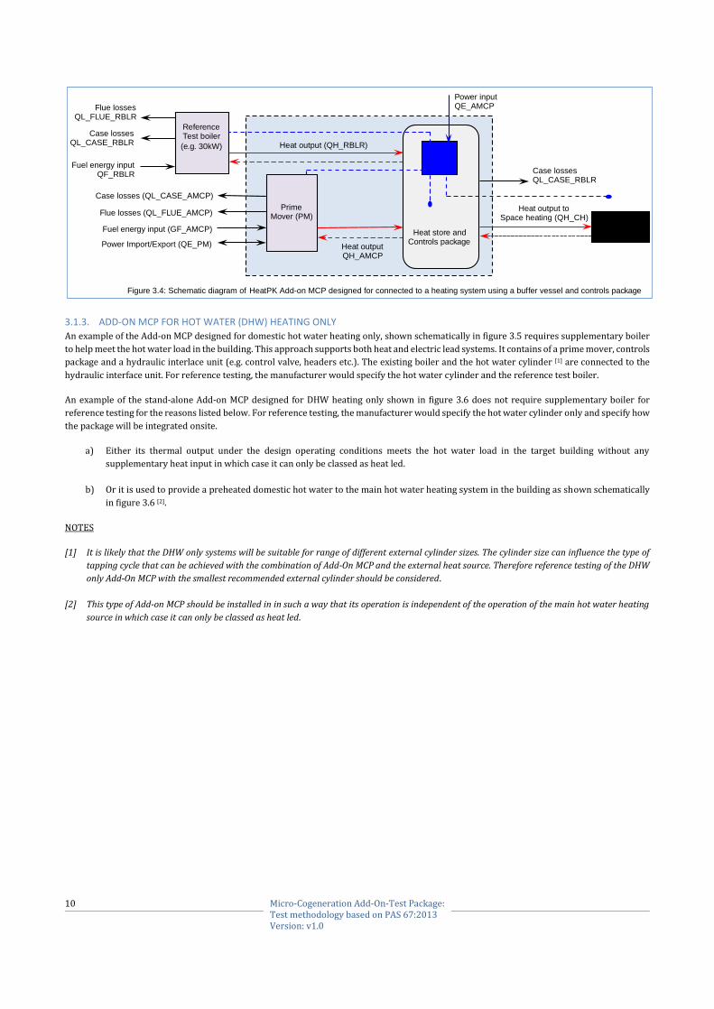
3.1.3. ADD-ON MCP FOR HOT WATER (DHW) HEATING ONLY
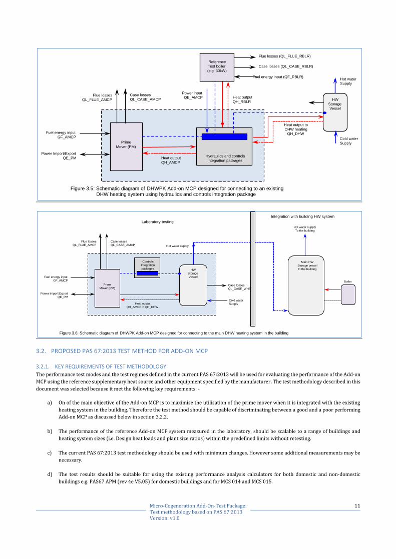
An example of the Add-on MCP designed for domestic hot water heating only, shown schematically in figure 3.5 requires supplementary boiler
to help meet the hot water load in the building. This approach supports both heat and electric lead systems. It contains of a prime mover, controls
package and a hydraulic interlace unit (e.g. control valve, headers etc.). The existing boiler and the hot water cylinder [1] are connected to the
hydraulic interface unit. For reference testing, the manufacturer would specify the hot water cylinder and the reference test boiler.
An example of the stand-alone Add-on MCP designed for DHW heating only shown in figure 3.6 does not require supplementary boiler for
reference testing for the reasons listed below. For reference testing, the manufacturer would specify the hot water cylinder only and specify how
the package will be integrated onsite.
a) Either its thermal output under the design operating conditions meets the hot water load in the target building without any
supplementary heat input in which case it can only be classed as heat led.
b) Or it is used to provide a preheated domestic hot water to the main hot water heating system in the building as shown schematically
in figure 3.6 [2].
NOTES
[1] It is likely that the DHW only systems will be suitable for range of different external cylinder sizes. The cylinder size can influence the type of
tapping cycle that can be achieved with the combination of Add-On MCP and the external heat source. Therefore reference testing of the DHW
only Add-On MCP with the smallest recommended external cylinder should be considered.
[2] This type of Add-on MCP should be installed in in such a way that its operation is independent of the operation of the main hot water heating
source in which case it can only be classed as heat led.
Fuel energy input (GF_AMCP)
Flue losses QL_FLUE_RBLR
Flue losses (QL_FLUE_AMCP)
Case losses (QL_CASE_AMCP)
Prime Mover (PM)
Power Import/Export (QE_PM) Heat output QH_AMCP
Heat output to Space heating (QH_CH)
Reference Test boiler
(e.g. 30kW)
Fuel energy input QF_RBLR
Case losses QL_CASE_RBLR
Power input QE_AMCP
Figure 3.4: Schematic diagram of HeatPK Add-on MCP designed for connected to a heating system using a buffer vessel and controls package
Heat store and Controls package
Heat output (QH_RBLR)
Case losses QL_CASE_RBLR
11 Micro-Cogeneration Add-On-Test Package: Test methodology based on PAS 67:2013 Version: v1.0
3.2. PROPOSED PAS 67:2013 TEST METHOD FOR ADD-ON MCP
3.2.1. KEY REQUIREMENTS OF TEST METHODOLOGY
The performance test modes and the test regimes defined in the current PAS 67:2013 will be used for evaluating the performance of the Add-on
MCP using the reference supplementary heat source and other equipment specified by the manufacturer. The test methodology described in this
document was selected because it met the following key requirements: -
a) On of the main objective of the Add-on MCP is to maximise the utilisation of the prime mover when it is integrated with the existing
heating system in the building. Therefore the test method should be capable of discriminating between a good and a poor performing
Add-on MCP as discussed below in section 3.2.2.
b) The performance of the reference Add-on MCP system measured in the laboratory, should be scalable to a range of buildings and
heating system sizes (i.e. Design heat loads and plant size ratios) within the predefined limits without retesting.
c) The current PAS 67:2013 test methodology should be used with minimum changes. However some additional measurements may be
necessary.
d) The test results should be suitable for using the existing performance analysis calculators for both domestic and non-domestic
buildings e.g. PAS67 APM (rev 4e V5.05) for domestic buildings and for MCS 014 and MCS 015.
Fuel energy input GF_AMCP
Flue losses
QL_FLUE_AMCP
Case losses QL_CASE_AMCP
Prime
Mover (PM)
Power Import/Export QE_PM Heat output
QH_AMCP
Heat output to DHW heating
QH_DHW
Cold water
Supply
Hot water Supply
HW Storage Vessel
Hydraulics and controls
Integration packages
Heat output QH_RBLR
Power input QE_AMCP
Figure 3.5: Schematic diagram of DHWPK Add-on MCP designed for connecting to an existing DHW heating system using hydraulics and controls integration package
Flue losses (QL_FLUE_RBLR)
Reference Test boiler
(e.g. 30kW)
Fuel energy input (QF_RBLR)
Case losses (QL_CASE_RBLR)
Fuel energy input GF_AMCP
Flue losses QL_FLUE_AMCP
Case losses QL_CASE_AMCP
Prime Mover (PM)
Power Import/Export QE_PM
Heat output QH_AMCP = QH_DHW
Cold water Supply
Hot water supply
HW
Storage Vessel
Controls Integration
packages
Figure 3.6: Schematic diagram of DHWPK Add-on MCP designed for connecting to the main DHW heating system in the building
Case losses QL_CASE_WHS
Main HW Storage vessel In the building
Hot water supply To the building
Laboratory testing
Integration with building HW system
Boiler

12 Micro-Cogeneration Add-On-Test Package: Test methodology based on PAS 67:2013 Version: v1.0
3.2.2. PRIME MOVER AND SUPPLEMENTARY HEAT SOURCE INTEGRATION
As shown schematically in figures 3.1 and 3.2, the Add-on MCP incorporating the prime mover (e.g. Fuel cell, ICE) and the supplementary heat
source (e.g. existing gas boiler) in the building are integrated onsite using controls and hydraulic integration packages supplied by the
manufacturer. The performance of the system therefore will depend upon the integration efficiency, load factor and plant size ratio etc.
The effect of system integration efficiency i.e.
installation of the Add-on MCP in a building and
integrating it with the existing heating system is
illustrated in figure 3.7.
Generally, the thermal output of the boiler will
be significantly higher than the thermal output
of the prime mover (Factor >5). Therefore if the
integration is inefficient e.g. the prime mover is
not the lead heat source, then the heat supplied
by the prime mover will not significantly change
with demand because the boiler will supply
most of the heat demand.
If the integration is efficient i.e. the prime mover
is always acting, as the lead heat source with
intelligent demand management then the heat
supplied by the prime mover will increase as the
heating load decreases resulting in increased
run hours for the prime mover.
3.2.3. TEST METHODOLOGY FOR THE ADD-ON MCP/MCU - GENERAL
a) All types of Add-on MCP/MCU should be tested as a complete package that is going to be supplied, installed and integrated with the
existing heating systems in buildings. The package (e.g. Prime mover, controls, hydraulics assembly, hot water vessel) should be
installed and operated in the laboratory as per manufacturer’s instructions.
b) The RegPK, HeatPK and CombiPK types of Add-on MCP/MCU should only be tested with a reference supplementary heat source e.g. a
gas boiler [1] specified by the manufacturer.
c) The DHWPK types of Add-on MCP designed for hot water heating only can be tested as follows configurations: -
1) If the DHWPK Add-on MCP designed to supply domestic hot water directly to the hot water outlets in the building and it requires
a supplementary boiler to help meet the hot water load in the building, then it should be tested with specified reference boiler.
The schematic diagram of this type of DHWPK Add-on MCP is shown in figure 3.5.
2) If the DHWPK is designed to supply domestic hot water to a hot water storage vessel in the building then it should be tested in
stand-alone mode without the reference test boiler. The stand-alone DHWPK may have a intermediate hot water storage vessel
as part of the Add-on MCP. The schematic diagram of stand-alone DHWPK Add-on MCP is shown in figure 3.6.
d) For reference testing the space heating power at 100% load factor should be within 10% of the rated output of the reference test boiler
at 80oC flow and 60oC return temperatures [2].
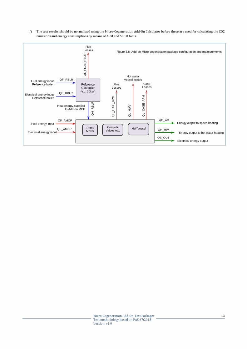
e) The generic configuration for reference testing the Add-on MCP system is shown in figure 3.8. In addition to the standard PAS 67:2013
performance measurements, the following additional measurements should be made: -
1) Fuel energy used by reference boiler (QF_RBLR)
2) Electrical energy used by reference boiler (QE_RBLR)
3) Flue losses from reference boiler (QL_FLUE_RBLR) for energy balance checks
4) Heat supplied by the reference boiler to Add-on MCP. This will allow the performance of the system to be calculated with different
efficiency band power rating of boilers.
In practice separate measurements of both reference boiler and the Add-On MCP heat inputs, flue CO2, flue condensate
production rates etc. are required. As a consequence it becomes harder, especially at part load tests, to satisfy the energy balance
limits set in the PAS 67:2013. Therefore it is recommended that new wider acceptable limits should be set which override those
set in PAS 67:2013.
0
20
40
60
80
100
120
0.0 2.0 4.0 6.0 8.0 10.0 12.0 14.0 16.0 18.0 20.0
Lo
ad
su
pplie
d b
y p
rim
e m
ove
r -
[%]
Heating load [kW]
Figure 3.7: Comparison between efficient and inefficient Add-on MCP Integration with existing supplementary boiler and heating system
Efficient Integration Inefficienct Integration
13 Micro-Cogeneration Add-On-Test Package: Test methodology based on PAS 67:2013 Version: v1.0
f) The test results should be normalized using the Micro-Cogeneration Add-On Calculator before these are used for calculating the CO2
emissions and energy consumptions by means of APM and SBEM tools.
Energy output to space heating
Energy output to hot water heating
Electrical energy output
Fuel energy input
Electrical energy input
Figure 3.8: Add-on Micro-cogeneration package configuration and measurements
Fuel energy input Reference boiler
Electrical energy input Reference boiler
Reference Gas boiler
(e.g. 30kW)
Heat energy supplied to Add-on MCP
QF_RBLR
QE_RBLR Q
H_
RB
LR
QL
_F
LU
E_
RB
LR
Flue Losses
Prime Mover
Controls Valves etc.
HW Vessel
QF_AMCP
QE_AMCP
Flue Losses
QL
_F
LU
E_
AP
M
Case Losses
QL
_C
AS
E_
AP
M
Hot water Vessel losses
QL_
HW
V
QH_CH
QH_HW
QE_OUT
14 Micro-Cogeneration Add-On-Test Package: Test methodology based on PAS 67:2013 Version: v1.0
NOTES
[1] In this document a 30kW-condensing boiler is used for calculating the performance of the reference test system as an example only to
illustrate the test methodology.
[2] Different heating flow and return temperatures may be used, provided these meet the relevant requirements of PAS 67:2013.
[3] The schematic diagrams 3.2, 3.4 and 3.6 shows hot water vessel as part of the Add-on MCP. However this may not always be the case and
is not a requirement. However the cylinder size can influence the type of tapping cycle that can be achieved with the combination of Add-
On MCP and the external heat source. Therefore reference testing of the DHW performance with the smallest recommended external
cylinder should be considered.
3.2.4. DHW TESTS FOR THE ADD-ON MCP/MCU
a) DHW performance test [1] should be carried out as per PAS67: 2013 at the hot water tapping cycle specified by the manufacturer for
Add-on MCP types RegPK, CombiPK and DHWPK.
b) DHW performance testing is not required for Add-on MCP designed for space heating only i.e. type HeatPK.
NOTES
[1] Depending upon the performance characteristics of the Add-on MCP/MCU, DHW performance tests at more than one hot water tapping
cycles should be considered.
3.2.5. SPACE HEATING TESTS FOR THE ADD-ON MCP/MCU
a) The space heating performance tests should be carried out as per PAS67: 2013 for Add-on MCP types RegPK, CombiPK and HeatPK
using 100% heating load, operating mode and control settings specified by the manufacturer,
b) The load PAS67: 2013 specifies that space heating performance tests should be carried out at least at 100%, 30% and 10% load factors.
Depending upon the performance characteristics of the Add-on MCP/MCU (see figure 3.7), space heating performance tests at
intermediate load factor should be considered. This will enable the APM calculator to predict the performance of the Add-on MCP more
accurately for installation dwellings. The permitted supplementary heat load tests depend upon the test regimes specified and are
listed in table 2.2.
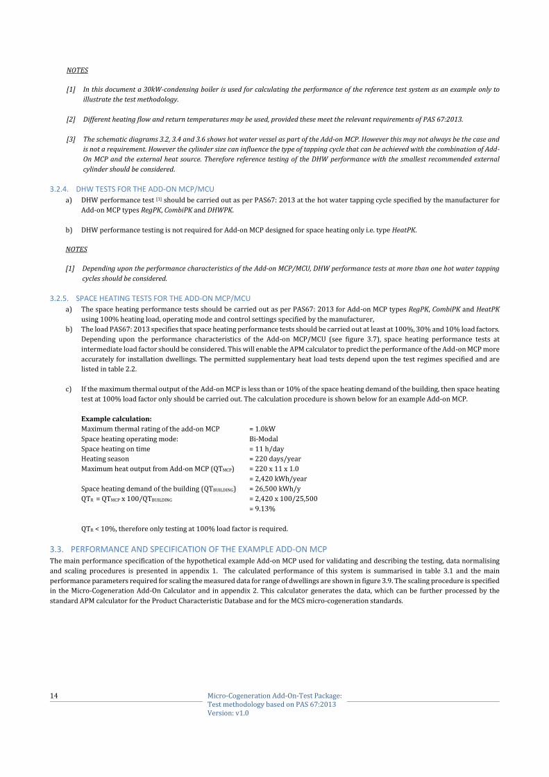
c) If the maximum thermal output of the Add-on MCP is less than or 10% of the space heating demand of the building, then space heating
test at 100% load factor only should be carried out. The calculation procedure is shown below for an example Add-on MCP.
Example calculation:
Maximum thermal rating of the add-on MCP = 1.0kW
Space heating operating mode: Bi-Modal
Space heating on time = 11 h/day
Heating season = 220 days/year
Maximum heat output from Add-on MCP (QTMCP) = 220 x 11 x 1.0
= 2,420 kWh/year
Space heating demand of the building (QTBUILDING) = 26,500 kWh/y
QTR = QTMCP x 100/QTBUILDING = 2,420 x 100/25,500
= 9.13%
QTR < 10%, therefore only testing at 100% load factor is required.
3.3. PERFORMANCE AND SPECIFICATION OF THE EXAMPLE ADD-ON MCP The main performance specification of the hypothetical example Add-on MCP used for validating and describing the testing, data normalising
and scaling procedures is presented in appendix 1. The calculated performance of this system is summarised in table 3.1 and the main
performance parameters required for scaling the measured data for range of dwellings are shown in figure 3.9. The scaling procedure is specified
in the Micro-Cogeneration Add-On Calculator and in appendix 2. This calculator generates the data, which can be further processed by the
standard APM calculator for the Product Characteristic Database and for the MCS micro-cogeneration standards.

15 Micro-Cogeneration Add-On-Test Package: Test methodology based on PAS 67:2013 Version: v1.0
Table 3.1 Calculated performance of the example Add-on MCP
Heating load Factor
Space heating Load
Heat supplied By Ref-Boiler
Estimated Ref-Boiler On-Time
Power used By Ref-Boiler
Gas used by By Ref-Boiler
Net CO2 Emissions
By Ref-Boiler
Total gas used
By System
Total CO2 Emissions By system
Total power Exported by
System
[%] [kWh/24h] [kWh/24h] [h/24h] [kWh/24h] [kWh/24h] [kgCO2/24h] [kWh/24h] [kgCO2/24h] [kWh/24h]
10.00 64.80 22.98 6.48 0.31 25.53 5.67 103.66 8.87 26.05
30.00 194.40 151.10 20.00 0.64 167.89 36.60 248.78 39.91 26.65
60.00 388.80 345.92 20.00 0.64 384.36 83.36 465.34 87.09 25.87
100.00 648.00 606.05 21.00 0.67 673.39 145.80 753.68 150.05 24.56
Standby mode
0.00 0.00 0.00 0.14 0.00 0.07 0.00 0.15 -0.29
DHW heating 5.85 0.37 0.042 0.15 0.42 0.16 14.00 0.95 4.00
0
10
20
30
40
50
60
70
80
90
0
100
200
300
400
500
600
700
800
900
0 100 200 300 400 500 600 700
Add-onM
CP:Fuelconsump=on,H
eatoutput
&Netpowergenerated
Boiler:Fuelconsump=on,H
eatoutput
Spacehea=ngload,[kWh/day]
Figure3.5:Calculatedperformancecharcteris=csoftheAdd-onMCP
Hea=ngloadsuppliedbyboiler[kWh/day] Fuelusedbyboiler[kWh/day]
Hea=ngloadsuppliedbyAdd-onMCP[kWh/day] FuelusedbyAdd-onMCP[kWh/day]
NetelectricitygeneratedbyAdd-onMCP[kWh/day]
Figure 3.9: Calculated performance characteristics of the example Add-on MCP
16 Micro-Cogeneration Add-On-Test Package: Test methodology based on PAS 67:2013 Version: v1.0
4. MICRO-COGENERATION ADD-ON CALCULATOR
4.1. OVERVIEW The excel workbook based “Micro-Cogeneration Add-On Calculator” has multiple input and output sheets which are described below in
section2. This calculator is an interface between the PAS 67:2013 performance test results and the current tools for demonstrating compliance
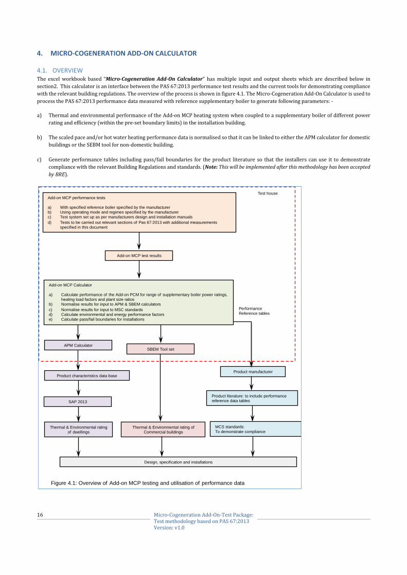
with the relevant building regulations. The overview of the process is shown in figure 4.1. The Micro-Cogeneration Add-On Calculator is used to
process the PAS 67:2013 performance data measured with reference supplementary boiler to generate following parameters: -
a) Thermal and environmental performance of the Add-on MCP heating system when coupled to a supplementary boiler of different power
rating and efficiency (within the pre-set boundary limits) in the installation building.
b) The scaled pace and/or hot water heating performance data is normalised so that it can be linked to either the APM calculator for domestic
buildings or the SEBM tool for non-domestic building.
c) Generate performance tables including pass/fail boundaries for the product literature so that the installers can use it to demonstrate
compliance with the relevant Building Regulations and standards. (Note: This will be implemented after this methodology has been accepted
by BRE).
Add-on MCP performance tests
a) With specified reference boiler specified by the manufacturer b) Using operating mode and regimes specified by the manufacturer
c) Test system set up as per manufacturers design and installation manuals
d) Tests to be carried out relevant sections of Pas 67:2013 with additional measurements
specified in this document
Product manufacturer
Add-on MCP test results
Add-on MCP Calculator
a) Calculate performance of the Add-on PCM for range of supplementary boiler power ratings, heating load factors and plant size ratios
b) Normalise results for input to APM & SBEM calculators
c) Normalise results for input to MSC standards d) Calculate environmental and energy performance factors
e) Calculate pass/fail boundaries for installations
APM Calculator
Product characteristics data base
SAP 2013
Thermal & Environmental rating of dwellings
SBEM Tool set
Thermal & Environmental rating of Commercial buildings
Performance
Reference tables
Product literature: to include performance reference data tables
MCS standards:
To demonstrate compliance
Design, specification and installations
Test house
Figure 4.1: Overview of Add-on MCP testing and utilisation of performance data
17 Micro-Cogeneration Add-On-Test Package: Test methodology based on PAS 67:2013 Version: v1.0
4.2. DESCRIPTION The excel workbook based “Micro-Cogeneration Add-On Calculator” has multiple input and output sheets i.e. Tabs with data input and output
tables calculating algorithms and these are described below. Where practical result table formats set out in PAS 67:2013 have been used.
4.2.1. TAB: “Manufacturer’s Declaration”
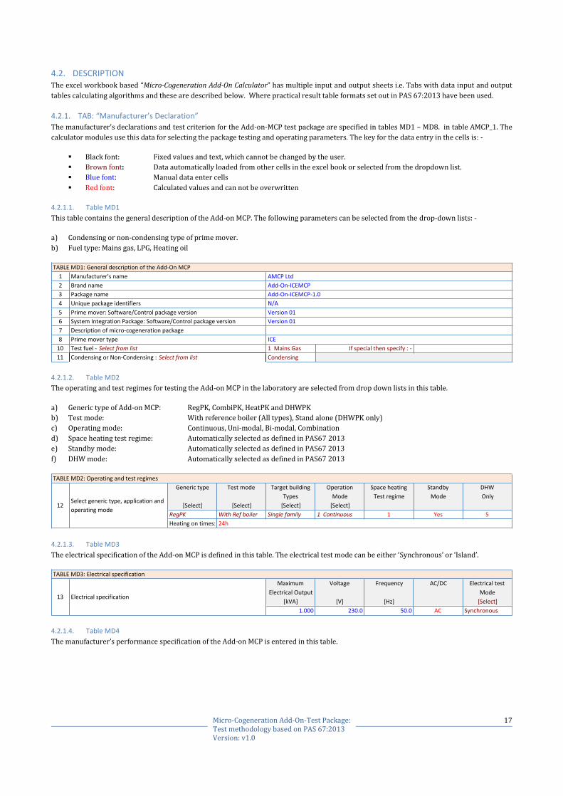
The manufacturer’s declarations and test criterion for the Add-on-MCP test package are specified in tables MD1 – MD8. in table AMCP_1. The
calculator modules use this data for selecting the package testing and operating parameters. The key for the data entry in the cells is: -
Black font: Fixed values and text, which cannot be changed by the user.
Brown font: Data automatically loaded from other cells in the excel book or selected from the dropdown list.
Blue font: Manual data enter cells
Red font: Calculated values and can not be overwritten
4.2.1.1. Table MD1
This table contains the general description of the Add-on MCP. The following parameters can be selected from the drop-down lists: -
a) Condensing or non-condensing type of prime mover.
b) Fuel type: Mains gas, LPG, Heating oil
4.2.1.2. Table MD2
The operating and test regimes for testing the Add-on MCP in the laboratory are selected from drop down lists in this table.
a) Generic type of Add-on MCP: RegPK, CombiPK, HeatPK and DHWPK
b) Test mode: With reference boiler (All types), Stand alone (DHWPK only)
c) Operating mode: Continuous, Uni-modal, Bi-modal, Combination
d) Space heating test regime: Automatically selected as defined in PAS67 2013
e) Standby mode: Automatically selected as defined in PAS67 2013
f) DHW mode: Automatically selected as defined in PAS67 2013
4.2.1.3. Table MD3
The electrical specification of the Add-on MCP is defined in this table. The electrical test mode can be either ‘Synchronous’ or ‘Island’.
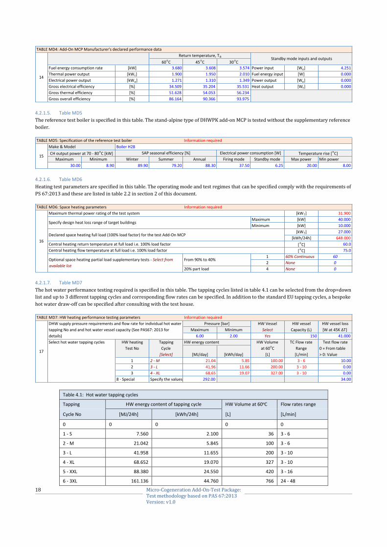
4.2.1.4. Table MD4
The manufacturer’s performance specification of the Add-on MCP is entered in this table.
1
2
3
4
5
6
7
8
10 1MainsGas
11 Condensing
Version01
Descriptionofmicro-cogenerationpackage
Manufacturer'sname
Brandname
Uniquepackageidentifiers
Primemover:Software/Controlpackageversion
SystemIntegrationPackage:Software/Controlpackageversion
TABLEMD1:GeneraldescriptionoftheAdd-OnMCP
Ifspecialthenspecify:-Testfuel-Selectfromlist
CondensingorNon-Condensing:Selectfromlist
ICE
Packagename
Primemovertype
AMCPLtd
Add-On-ICEMCP
Add-On-ICEMCP-1.0
N/A
Version01
Generictype Testmode Targetbuilding Operation Spaceheating Standby DHW
Types Mode Testregime Mode Only
[Select] [Select] [Select] [Select]
RegPK WithRefboiler Singlefamily 1Continuous 1 Yes 5
Heatingontimes: 24h
Selectgenerictype,applicationand
operatingmode12
TABLEMD2:Operatingandtestregimes
Maximum Voltage Frequency AC/DC Electricaltest
ElectricalOutput Mode
[kVA] [V] [Hz] [Select]
1.000 230.0 50.0 AC Synchronous
TABLEMD3:Electricalspecification
Electricalspecification13
18 Micro-Cogeneration Add-On-Test Package: Test methodology based on PAS 67:2013 Version: v1.0
4.2.1.5. Table MD5
The reference test boiler is specified in this table. The stand-alpine type of DHWPK add-on MCP is tested without the supplementary reference
boiler.
4.2.1.6. Table MD6
Heating test parameters are specified in this table. The operating mode and test regimes that can be specified comply with the requirements of
PS 67:2013 and these are listed in table 2.2 in section 2 of this document.
4.2.1.7. Table MD7
The hot water performance testing required is specified in this table. The tapping cycles listed in table 4.1 can be selected from the drop=down
list and up to 3 different tapping cycles and corresponding flow rates can be specified. In addition to the standard EU tapping cycles, a bespoke
hot water draw-off can be specified after consulting with the test house.
Table 4.1: Hot water tapping cycles
Tapping HW energy content of tapping cycle HW Volume at 60oC Flow rates range
Cycle No [MJ/24h] [kWh/24h] [L] [L/min]
0 0 0 0 0
1 - S 7.560 2.100 36 3 - 6
2 - M 21.042 5.845 100 3 - 6
3 - L 41.958 11.655 200 3 - 10
4 - XL 68.652 19.070 327 3 - 10
5 - XXL 88.380 24.550 420 3 - 16
6 - 3XL 161.136 44.760 766 24 - 48
60oC 45oC 30oC
Fuelenergyconsumptionrate [kW] 3.680 3.608 3.574 Powerinput [We] 4.251
Thermalpoweroutput [kWt] 1.900 1.950 2.010 Fuelenergyinput [W] 0.000
Electricalpoweroutput [kWe] 1.271 1.310 1.349 Poweroutput [We] 0.000
Grosselectricalefficiency [%] 34.509 35.204 35.531 Heatoutput [Wt] 0.000
Grossthermalefficiency [%] 51.628 54.053 56.234
Grossoverallefficiency [%] 86.164 90.366 93.975
Returntemperature,TR Standbymodeinputsandoutputs
14
TABLEMD4:Add-OnMCPManufacturer'sdeclaredperformancedata
Informationrequired
BoilerH28
Maximum Minimum Winter Summer Annual Firingmode Standbymode Maxpower Minpower
30.00 8.90 89.90 79.20 88.30 37.50 6.25 20.00 8.00
TABLEMD5:Specificationofthereferencetestboiler
SAPseasonalefficiency[%] Electricalpowerconsumption[W] Temperaturerise[oC]
15
Make&Model
CHoutputpowerat70-80oC[kW]
TABLEMD6:Spaceheatingparameters Informationrequired
[kWT] 31.900
Maximum [kW] 40.000
Minimum [kW] 10.000
[kWT] 27.000
[kWh/24h] 648.000
[oC] 60.0
[oC] 75.0
1 60%Continuous 60
2 None 0
4 None 0
From90%to40%
20%partload
Centralheatingflowtemperatureatfullloadi.e.100%loadfactor
16
Specifydesignheatlossrangeoftargetbuildings
Maximumthermalpowerratingofthetestsystem
Declaredspaceheatingfullload(100%loadfactor)forthetestAdd-OnMCP
Centralheatingreturntemperatureatfullloadi.e.100%loadfactor
Optionalspaceheatingpartialloadsupplementarytests-Selectfrom
availablelist
TABLEMD7:HWheatingperformancetestingparameters Informationrequired
HWVessel HWvessel HWvesselloss
Maximum Minimum Select Capacity(L) [Wat45KΔT]
6.00 2.00 Yes 150 41.000
Selecthotwatertappingcycles HWheating Tapping HWenergycontent HWVolume TCFlowrate Testflowrate
TestNo Cycle at60oC Range 0=Fromtable
[Select] [MJ/day] [kWh/day] [L] [L/min] >0:Value
1 2-M 21.04 5.85 100.00 3-6 10.00
2 3-L 41.96 11.66 200.00 3-10 0.00
3 4-XL 68.65 19.07 327.00 3-10 0.00
8-Special Specifythevalues 292.00 34.00
DHWsupplypressurerequirementsandflowrateforindividualhotwater
tappingNoandandhotwatervesselcapacity(SeePAS67:2013for
details)
17
Pressure[bar]
19 Micro-Cogeneration Add-On-Test Package: Test methodology based on PAS 67:2013 Version: v1.0
7 - 4XL 336.672 93.520 1600 48 - 96
8 - Special 292.000 1,051.200 1845 34.00
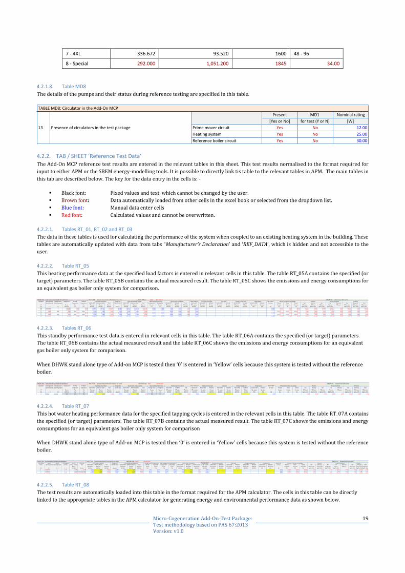
4.2.1.8. Table MD8
The details of the pumps and their status during reference testing are specified in this table.
4.2.2. TAB / SHEET ‘Reference Test Data’
The Add-On MCP reference test results are entered in the relevant tables in this sheet. This test results normalised to the format required for
input to either APM or the SBEM energy-modelling tools. It is possible to directly link tis table to the relevant tables in APM. The main tables in
this tab are described below. The key for the data entry in the cells is: -
Black font: Fixed values and text, which cannot be changed by the user.
Brown font: Data automatically loaded from other cells in the excel book or selected from the dropdown list.
Blue font: Manual data enter cells
Red font: Calculated values and cannot be overwritten.
4.2.2.1. Tables RT_01, RT_02 and RT_03
The data in these tables is used for calculating the performance of the system when coupled to an existing heating system in the building. These
tables are automatically updated with data from tabs “Manufacturer’s Declaration’ and ‘REF_DATA’, which is hidden and not accessible to the
user.
4.2.2.2. Table RT_05
This heating performance data at the specified load factors is entered in relevant cells in this table. The table RT_05A contains the specified (or
target) parameters. The table RT_05B contains the actual measured result. The table RT_05C shows the emissions and energy consumptions for
an equivalent gas boiler only system for comparison.
4.2.2.3. Tables RT_06
This standby performance test data is entered in relevant cells in this table. The table RT_06A contains the specified (or target) parameters.
The table RT_06B contains the actual measured result and the table RT_06C shows the emissions and energy consumptions for an equivalent
gas boiler only system for comparison.
When DHWK stand alone type of Add-on MCP is tested then ‘0’ is entered in ‘Yellow’ cells because this system is tested without the reference
boiler.
4.2.2.4. Table RT_07
This hot water heating performance data for the specified tapping cycles is entered in the relevant cells in this table. The table RT_07A contains
the specified (or target) parameters. The table RT_07B contains the actual measured result. The table RT_07C shows the emissions and energy
consumptions for an equivalent gas boiler only system for comparison
When DHWK stand alone type of Add-on MCP is tested then ‘0’ is entered in ‘Yellow’ cells because this system is tested without the reference
boiler.
4.2.2.5. Table RT_08
The test results are automatically loaded into this table in the format required for the APM calculator. The cells in this table can be directly
linked to the appropriate tables in the APM calculator for generating energy and environmental performance data as shown below.
Present MD1 Nominalrating
[YesorNo] fortest(YorN) [W]
Yes No 12.00
Yes No 25.00
Yes No 30.00
Primemovercircuit
Heatingsystem
Presenceofcirculatorsinthetestpackage
TABLEMD8:CirculatorintheAdd-OnMCP
13
Referenceboilercircuit
TABLERT_05B:Laboratorymeasurementsofthereferencetestsystem RegPK WithRefboiler TABLERT-05C:Comparativegasboilersystem
Loadfactor Heatingsystem Heatingsystem Heatingload CHFlow CHReturn Averagefuel Powerproduced Add-OnMCP
Operatingmode Operatingregime Temperature Temperature Add-OnMCP ReferenceBoiler Total Calorificvalue Add-OnMCP ReferenceBoiler Total Averagereturn Averageflow Add-OnMCP RefBoiler Total Add-OnMCP Add-OnMCP RefBoiler Add-OnMCP RefBoiler Add-OnMCP RefBoiler ByAdd-OnMCP RefBoiler OnHours Thermal Power Overall Fuel Electricity Net Fuel Electricity Fuel Electricity Total
LF QSH_(LF) TCHF TCHF QF(LF)-AMCP QF(LF)-RB QF(LF)_TOT QSH(LF)-AMCP QSH(LF)-RB QSH(LF)_TOT TSH_AR(LF) TSH_AF(LF) QPIN-AMCP(LF) QPIN-RB(LF) QPIN-TOT(LF) QPOUT-AMCP(LF) QFL_AMCP(LF) QFL_RB(LF) QCL_AMCP(LF) QCL_RB(LF) QΔAMCP(LF) QΔRB(LF) QBAL_AMCP(LF) QBAL_RB(LF) ƞTH_RS(LF) ƞEL_RS(LF) ƞTOT_RS(LF) CO2FUEL(LF) CO2ELEC(LF) CO2NET(LF) QF(LF)-GS QPIN-GS(LF) CO2 FUEL-GS(LF) CO2ELEC-GS(LF) CO2NET-GS(LF)
[%] [-] [-] [MJ/24h] [oC] [oC] [MJ/24h] [MJ/24h] [MJ/24h] [MJ/m3] [MJ/24h] [MJ/24h] [MJ/24h] [oC] [oC] [MJ/24h] [MJ/24h] [MJ/24h] [MJ/24h] [MJ/24h] [MJ/24h] [MJ/24h] [MJ/24h] [MJ/24h] [MJ/24h] [MJ] [MJ] [h] [%] [%] [%] [kgCO2/24h] [kgCO2/24h] [kgCO2/24h] [kgCO2/24h] [kgCO2/24h] [kgCO2/24h] [kgCO2/24h]
100 Continuous 1 2,332.800 60.00 75.00 262.861 2,433.027 2,695.889 40.068 134.611 2,116.734 2,251.345 58.930 73.890 2.166 2.567 4.733 87.037 19.640 83.510 3.053 86.563 161.753 -11.865 149.888 2,504.277 3.650 150.257 0.526 150.783
60 Continuous 1 1,399.680 42.86 51.86 255.117 1,311.950 1,567.067 40.100 138.154 1,167.635 1,305.789 43.800 53.800 2.146 2.572 4.718 89.977 19.680 83.327 5.441 88.768 94.024 -12.292 81.733 1,452.491 3.645 87.149 0.525 87.675
0 #N/A N/A 0.000 #N/A #N/A 0.000 0.000 0.000 0.000 0.000 0.000 0.000 0.000 0.000 0.000 0.000 #DIV/0! #DIV/0! #DIV/0! 0.000 0.000 0.000 0.000 0.000 0.000 0.000 0.000
30 Continuous 1 699.840 30.00 35.00 247.059 624.683 871.741 39.996 138.931 565.338 704.269 29.950 39.230 2.385 2.509 4.894 90.478 19.200 80.789 9.818 90.606 52.304 -12.338 39.966 783.392 3.701 47.003 0.534 47.537
0 #N/A N/A 0.000 #N/A #N/A 0.000 0.000 0.000 0.000 0.000 0.000 0.000 0.000 0.000 0.000 0.000 #DIV/0! #DIV/0! #DIV/0! 0.000 0.000 0.000 0.000 0.000 0.000 0.000 0.000
10 Continuous 1 233.280 30.00 35.00 232.860 109.724 342.584 40.012 130.248 99.849 230.097 30.230 37.750 2.981 2.352 5.333 84.823 18.000 67.165 23.203 90.368 20.555 -11.460 9.095 255.948 3.843 15.357 0.554 15.911
TABLERT_05A:Targetparametersspecifiedbythemanufacturer Add-OnMCPtype:
Fuelenergyconsumption Spaceheatingenergysupplied Spaceheatingtemperatures Electricpowerconsumption Energyconsumption EmissionsFluelosses(Grossbasis) Caselosses Changeinenergylevel Energybalance Efficiencyofreferencetestpackage Emissions
TABLERT_06B:Laboratorymeasurementsofthereferencetestsystem RegPK WithRefboiler TABLERT-06C:Comparativegasboilersystem
Loadfactor Heatingsystem Heatingsystem Heatingload CHFlow CHReturn Averagefuel Powerproduced Add-OnMCP
Operatingmode Operatingregime Temperature Temperature Add-OnMCP ReferenceBoiler Total Calorificvalue Add-OnMCP ReferenceBoiler Total Averagereturn Averageflow Add-OnMCP RefBoiler Total Add-OnMCP Add-OnMCP RefBoiler Add-OnMCP RefBoiler Add-OnMCP RefBoiler ByAdd-OnMCP RefBoiler OnHours Thermal Power Overall Fuel Electricity Net Fuel Electricity Fuel Electricity Total
LF QSH_(LF) TCHF TCHF QF(LF)-AMCP QF(LF)-RB QF(LF)_TOT QSH(LF)-AMCP QSH(LF)-RB QSH(LF)_TOT TSH_AR(LF) TSH_AF(LF) QPIN-AMCP(LF) QPIN-RB(LF) QPIN-TOT(LF) QPOUT-AMCP(LF) QFL_AMCP(LF) QFL_RB(LF) QCL_AMCP(LF) QCL_RB(LF) QΔAMCP(LF) QΔRB(LF) QBAL_AMCP(LF) QBAL_RB(LF) ƞTH_RS(LF) ƞEL_RS(LF) ƞTOT_RS(LF) CO2FUEL(LF) CO2ELEC(LF) CO2NET(LF) QF(LF)-GS QPIN-GS(LF) CO2FUEL-GS(LF) CO2ELEC-GS(LF) CO2NET-GS(LF)
[%] [-] [-] [MJ/24h] [oC] [oC] [MJ/24h] [MJ/24h] [MJ/24h] [MJ/m3] [MJ/24h] [MJ/24h] [MJ/24h] [oC] [oC] [MJ/24h] [MJ/24h] [MJ/24h] [MJ/24h] [MJ/24h] [MJ/24h] [MJ/24h] [MJ/24h] [MJ/24h] [MJ/24h] [MJ] [MJ] [h] [%] [%] [%] [kgCO2/24h] [kgCO2/24h] [kgCO2/24h] [kgCO2/24h] [kgCO2/24h] [kgCO2/24h] [kgCO2/24h]
0 Standby Standby N/A N/A N/A 0.000 0.000 0.000 39.998 0.000 0.000 0.000 N/A N/A 0.358 0.297 0.655 0.000 0.000 0.000 0.094 0.094 0.000 0.297 0.000 0.043 0.043
Caselosses Changeinenergylevel Energybalance
TABLERT_06A:Targetparametersspecifiedbythemanufacturer
Fuelenergyconsumption Spaceheatingenergysupplied Spaceheatingtemperatures
Add-OnMCPtype:
Electricpowerconsumption Energyconsumption EmissionsEfficiencyofreferencetestpackage EmissionsFluelosses(Grossbasis)
TABLERT_07A:Targetparametersspecifiedbythemanufacturer TABLERT_07B:Laboratorymeasurementsofthereferencetestsystem RegPK WithRefboiler TABLERT-07C:Comparativegasboilersystem
HWheating System System DHWtapping DHWTC DHWFlow Averagefuel Powerproduced Add-OnMCP
TestNo Operatingmode Operatingregime CycleNo Energycontent Rate Add-OnMCP ReferenceBoiler Total Calorificvalue Add-OnMCP ReferenceBoiler Total InletCW OutletHW Averagereturn Averageflow Add-OnMCP RefBoiler Reftestsystem ByAdd-OnMCP Add-OnMCP RefBoiler Add-OnMCP RefBoiler Add-OnMCP RefBoiler Add-OnMCP RefBoiler OnHours Thermal Power Overall Fuel Electricity Net Fuel Electricity Fuel Electricity Total
QHW_(N) QFHW-AMCP(N) QFHW-RB(N) QFHW-TOT(N) QHW-AMCP(N) QHW-RB(N) QHW_TOT(N) TA-CW(N) TA-HW(N) TA-PR(N) TA-PF(N) QPIN-HW-AMCP(N) QPIN-HW-RB(N) QPIN-HW-TOT(N) QPOUT-HW(N) QFL-HW-AMCP(N) QFL-HW-RB(N) QCL-HW-AMCP(N) QCL-HW-RB(N) QΔAMCP-HW(N) QΔRB-HW(N) QBAL-AMCP-HW(N) QBAL-RB-HW(N) ƞTH-RS-HW(N) ƞEL-RS-HW(N) ƞTOT-RS-HW(N) CO2 FUEL-HW(N) CO2ELEC-HW(N) CO2NET-HW(N) QF(LF)-GS QPIN-GS(LF) CO2 FUEL-GS(LF) CO2ELEC-GS(LF) CO2NET-GS(LF)
[%] [-] [-] [-] [MJ/24h] [L/min] [MJ/24h] [MJ/24h] [MJ/24h] [MJ/m3] [MJ/24h] [MJ/24h] [MJ/24h] [
oC] [
oC] [
oC] [
oC] [MJ/24h] [MJ/24h] [MJ/24h] [MJ/24h] [MJ/24h] [MJ/24h] [MJ/24h] [MJ/24h] [MJ/24h] [MJ/24h] [MJ] [MJ] [h] [%] [%] [%] [kgCO2/24h] [kgCO2/24h] [kgCO2/24h] [kgCO2/24h] [kgCO2/24h] [kgCO2/24h] [kgCO2/24h]
1 Continuous 5 2-M 21.042 10.00 45.822 0.000 45.822 39.989 23.657 0.000 23.657 9.95 57.50 58.93 73.22 0.862 0.415 1.277 15.945 3.471 51.628 32.010 83.638 1.42 -2.11 -0.70 26.792 0.846 1.607 0.122 1.729
2 Continuous 5 3-L 41.958 FromPAS63table 77.935 5.416 83.351 40.050 40.236 4.744 44.980 10.12 58.00 57.34 72.39 1.118 0.437 1.555 27.032 5.897 53.965 30.566 84.531 2.41 -3.67 -1.26 50.940 0.996 3.056 0.144 3.200
3 Continuous 5 4-XL 68.652 FromPAS63table 116.629 15.034 131.664 40.072 60.213 13.185 73.398 10.20 57.50 58.12 74.10 1.434 0.503 1.937 40.698 8.904 55.747 29.439 85.186 3.61 -5.59 -1.98 83.123 1.220 4.987 0.176 5.163
Add-OnMCPtype:
Energyconsumption EmissionsFuelenergyconsumption DHWheatingloadsuppliedby Energybalance Efficiencyofreferencetestpackage EmissionsDHWheatingprimarytemperaturesAverageDraw-offtemperatures Electricpowerconsumption Fluelosses(Grossbasis) Caselosses Changeinenergylevel
20 Micro-Cogeneration Add-On-Test Package: Test methodology based on PAS 67:2013 Version: v1.0
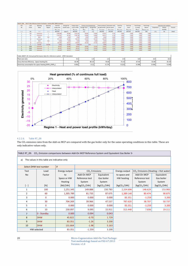
4.2.2.6. Table RT_09
The CO2 emission rates from the Add-on MCP are compared with the gas boiler only for the same operating conditions in this table. These are
only indicative values only.
TableRT_08A:PAS67Table:ReferenceSystemTestResults-UsedbyAPM/SBEMCalculators
Test Load Operating Operating Totalfuel Averagefuel Energyoutput Powerproduced Totalpowerused TotalFlue TotalCase TotalChange TotalEnergy
No Factor Mode Regime Energyused Calorificvalue toSHorDHW Averagereturn Averageflow ByAdd-OnMCP Reftestsystem Losses Losses Inenergy Balance Temperature Relative Pressure
QFUEL_TOTAL QSH_TOTAL TAPCR TAPCF EOUT-AOMCP E IN-RT_SYSTEM QFLUE_TOTAL QCASE_TOTAL QΔTOTAL QBALANCE_TOTAL Humidity
[-] [%] [-] [-] [MJ/24h] [MJ/m3] [MJ/24h] [oC] [oC] [MJ/24h] [MJ/24h] [MJ/24h] [MJ/24h] [MJ/24h] [MJ] [oC] [%] [mbar]
1 100 Continuous 1 2,695.889 40.068 2,251.345 58.930 73.890 87.037 4.733 0.000 0.000 0.000 0.000
2 60 Continuous 1 1,567.067 40.100 1,305.789 43.800 53.800 89.977 4.718 0.000 0.000 0.000 0.000
3 0 #N/A N/A 0.000 0.000 0.000 0.000 0.000 0.000 0.000 0.000 0.000 0.000 0.000
4 30 Continuous 1 871.741 39.996 704.269 29.950 39.230 90.478 4.894 0.000 0.000 0.000 0.000
5 0 #N/A N/A 0.000 0.000 0.000 0.000 0.000 0.000 0.000 0.000 0.000 0.000 0.000
6 10 Continuous 1 342.584 40.012 230.097 30.230 37.750 84.823 5.333 0.000 0.000 0.000 0.000
7 0 Standby Standby 0.000 39.998 0.000 N/A N/A 0.000 0.655 0.000 0.000 0.000 0.000
8 DHW Continuous 5 45.822 39.989 45.822 58.930 73.220 15.945 1.277 0.000 0.000 0.000 0.000
9 DHW Continuous 5 83.351 40.050 83.351 57.340 72.390 27.032 1.555 0.000 0.000 0.000 0.000
10 DHW Continuous 5 131.664 40.072 131.664 58.120 74.100 40.698 1.937 0.000 0.000 0.000 0.000
LaboratorytestconditionsPrimarycircuittemperatures
0.5 1.0 1.5 2.0 3.0 6.0 10.0
82.90 80.10 76.60 73.10 67.40 53.00 65.30
-0.062 -0.12 -0.174 -0.223 -0.308 -0.436 -0.349
Plantsizeratio
Grossthermalefficiency-Spaceheating(%)
Electricityconsumptionforspaceheating(KWhE/kWhH)
TableAMCP_R2:Annualperformancedataforreferencesystem-APMCalculator

21 Micro-Cogeneration Add-On-Test Package: Test methodology based on PAS 67:2013 Version: v1.0
.
4.2.3. TAB/SHEET ‘Installation Package’
This is the main calculator for scaling and normalising the Add-on MCP performance results measured with the reference boiler. The key for the
data entry in the cells is: -
Black font: Fixed values and text, which cannot be changed by the user.
Brown font: Data automatically loaded from other cells in the excel book or selected from the dropdown list.
Blue font: Manual data enter cells
Red font: Calculated values and cannot be overwritten
The methodology used for scaling the reference test results to the system in the installation dwelling is described in this document as “Micro-
Cogeneration Add-On Calculator Algorithms” and summarised in appendix 2. These algorithms are embedded in the hidden calculating tables in
this sheet and are based on the key assumptions listed in section 4.2.3.1.
4.2.3.1. Assumptions
a) General
The space heating flow and return temperatures for the installation system are the same as the reference test boiler.
The heating operating mode (e.g. continuous, bimodal etc.) is same the reference test system.
The system control logic and controls for optimizing the operation of the prime mover in the Add-On MCP are same.
The modulation band of the new boiler is similar to that of the reference boiler.
b) Standby performance
Standby performance of the Add-On-MCP is independent of the size and type of the building and the thermal output rating of the
supplementary boiler.
The supplementary boiler will be off during the standby-operating mode of the system. Therefore only the standby power
consumption of the installation boiler will affect the standby heat loss tests carried out with the reference boiler.
c) DHW heating performance
It is assumed that the control logic, control parameters and the controls used in the installation system are same as those used in
reference PAS 67 DHW heating tests.
The DHW heating performance the system in the installation dwelling will depend upon the hot water heating load.
The methodology used for calculating the hot water heating performance depends upon the number of reference DHW heating tests
carried out (e.g. Tapping cycles: 0, 1, 2 or 3) and this is specified in appendix 1.
d) Space heating performance
It is assumed that the control logic, control parameters and the controls used in the installation system are same as those used in
reference PAS 67 DHW heating tests.
Although the space heating thermal energy supplied by the Add-On-MCP and its performance will not significantly change when the
boiler in the installation building replaces the reference test boiler, it will change with the design heat loss of the building.
The electricity produced by the Add-On-MCP when in space heating mode will depend upon the thermal load but will not be
significantly affected when the installation boiler replaces the reference test boiler.
The electricity consumed by the installation boiler system will depend upon the standby power consumption and this has been taken
into account in the calculating procedures.
The methodology used for calculating the space heating performance depends upon the number of reference heating tests carried out
and this is specified below.
4.2.3.2. Table IS_01
The main parameters of the installation building and the heating system are specified in this table. The boundary conditions are pre-set and
depend upon the rating of the reference test boiler and design heat loss of the building.
TABLEIS_01:Specificationoftheboilerandspaceheatingsystemintheinstallationdwelling
Symbol Unit Value
QTB_MAX [kW] 15.000 RangeMin-Max: 15.00 48.00
QTB_MIN [kW] 5.000
BLR_MB [-] 0.333
Winter ηW [%] 85.000
Summer ηS [%] 77.000
Annual ηA [%] 84.000
DHL [kW] 12.000
[kW] 12.000
[MJ/24h] 1,036.800
Firingmode QPB_FM [W] 30.000
Standbymode QPB_SM [W] 5.500
Notes
Boilerturndownration(Min/Max)
Minimumratingoftheboiler-(Heatingmodei.e.80/60oC)
Maximumratingoftheboiler-(Heatingmodei.e.80/60oC)
Boilerefficiency
Designheatlossofthebuilding Ok
OkMaximumpowerratingoftheAdd-OnMCPsystem(100%Loadfactor) QTSH_MAX
StandbypowerconsumptionoftheboilerEnter'0'ForDHWPKStandalonetype
Enter'0'ForDHWPKStandalonetype
Ok
22 Micro-Cogeneration Add-On-Test Package: Test methodology based on PAS 67:2013 Version: v1.0
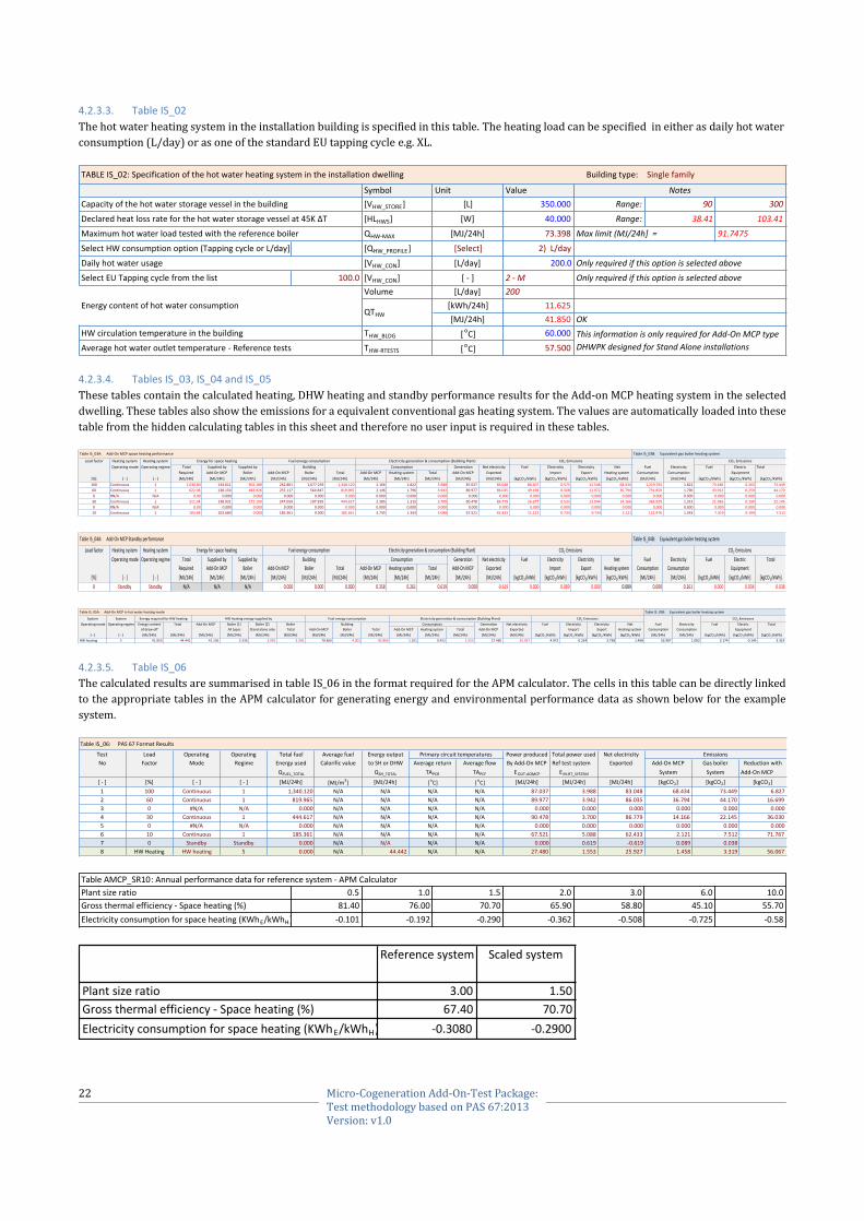
4.2.3.3. Table IS_02
The hot water heating system in the installation building is specified in this table. The heating load can be specified in either as daily hot water
consumption (L/day) or as one of the standard EU tapping cycle e.g. XL.
4.2.3.4. Tables IS_03, IS_04 and IS_05
These tables contain the calculated heating, DHW heating and standby performance results for the Add-on MCP heating system in the selected
dwelling. These tables also show the emissions for a equivalent conventional gas heating system. The values are automatically loaded into these
table from the hidden calculating tables in this sheet and therefore no user input is required in these tables.
4.2.3.5. Table IS_06
The calculated results are summarised in table IS_06 in the format required for the APM calculator. The cells in this table can be directly linked
to the appropriate tables in the APM calculator for generating energy and environmental performance data as shown below for the example
system.
TABLEIS_02:Specificationofthehotwaterheatingsystemintheinstallationdwelling Buildingtype: Singlefamily
Symbol Unit Value
[VHW_STORE] [L] 350.000 Range: 90 300
[HLHWS] [W] 40.000 Range: 38.41 103.41
QHW-MAX [MJ/24h] 73.398 91.7475
SelectHWconsumptionoption(TappingcycleorL/day] [QHW_PROFILE] [Select] 2)L/day
[VHW_CON] [L/day] 200.0
SelectEUTappingcyclefromthelist 100.0 [VHW_CON] [-] 2-M
Volume [L/day] 200
[kWh/24h] 11.625
[MJ/24h] 41.850 OK
THW_BLDG [oC] 60.000
THW-RTESTS [oC] 57.500
Maximumhotwaterloadtestedwiththereferenceboiler
Capacityofthehotwaterstoragevesselinthebuilding
Declaredheatlossrateforthehotwaterstoragevesselat45KΔT
Dailyhotwaterusage
QTHW
HWcirculationtemperatureinthebuilding
Averagehotwateroutlettemperature-Referencetests
Energycontentofhotwaterconsumption
Notes
Maxlimit(MJ/24h]=
Onlyrequiredifthisoptionisselectedabove
Onlyrequiredifthisoptionisselectedabove
ThisinformationisonlyrequiredforAdd-OnMCPtype
DHWPKdesignedforStandAloneinstallations
TableIS_03A:Add-OnMCPspaceheatingperformance TableIS_03B:Equivalentgasboilerheatingsystem
Loadfactor Heatingsystem Heatingsystem
Operatingmode Operatingregime Total Suppliedby Suppliedby Building Generation Netelectricity Fuel Electricity Electricity Net Fuel Electricity Fuel Electric Total
Required Add-OnMCP Boiler Add-OnMCP Boiler Total Add-OnMCP Heatingsystem Total Add-OnMCP Exported Import Export Heatingsystem Consumption Consumption Equipment
[%] [-] [-] [MJ/24h] [MJ/24h] [MJ/24h] [MJ/24h] [MJ/24h] [MJ/24h] [MJ/24h] [MJ/24h] [MJ/24h] [MJ/24h] [MJ/24h] [kgCO2/kWh] [kgCO2/kWh] [kgCO2/kWh] [kgCO2/kWh] [MJ/24h] [MJ/24h] [kgCO2/kWh] [kgCO2/kWh] [kgCO2/kWh]
100 Continuous 1 1,036.80 134.611 902.189 262.861 1,077.259 1,340.120 2.166 1.822 3.988 87.037 83.048 80.407 0.575 12.548 68.434 1,219.765 1.822 73.186 0.263 73.449
60 Continuous 1 622.08 138.154 483.926 255.117 564.847 819.965 2.146 1.796 3.942 89.977 86.035 49.198 0.568 12.972 36.794 731.859 1.796 43.912 0.259 44.170
0 #N/A N/A 0.00 0.000 0.000 0.000 0.000 0.000 0.000 0.000 0.000 0.000 0.000 0.000 0.000 0.000 0.000 0.000 0.000 0.000 0.000 0.000
30 Continuous 1 311.04 138.931 172.109 247.059 197.559 444.617 2.385 1.315 3.700 90.478 86.779 26.677 0.533 13.044 14.166 365.929 1.315 21.956 0.190 22.145
0 #N/A N/A 0.00 0.000 0.000 0.000 0.000 0.000 0.000 0.000 0.000 0.000 0.000 0.000 0.000 0.000 0.000 0.000 0.000 0.000 0.000 0.000
10 Continuous 1 103.68 103.680 0.000 185.361 0.000 185.361 3.745 1.343 5.088 67.521 62.433 11.122 0.733 9.734 2.121 121.976 1.343 7.319 0.194 7.512
Fuelenergyconsumption Electricitygeneration&consumption(BuildingPlant) CO2EmissionsEnergyforspaceheating
Consumption
CO2Emissions
TableIS_04A:Add-OnMCPStandbyperformance TableIS_04B:Equivalentgasboilerheatingsystem
Loadfactor Heatingsystem Heatingsystem
Operatingmode Operatingregime Total Suppliedby Suppliedby Building Generation Netelectricity Fuel Electricity Electricity Net Fuel Electricity Fuel Electric Total
Required Add-OnMCP Boiler Add-OnMCP Boiler Total Add-OnMCP Heatingsystem Total Add-OnMCP Exported Import Export Heatingsystem Consumption Consumption Equipment
[%] [-] [-] [MJ/24h] [MJ/24h] [MJ/24h] [MJ/24h] [MJ/24h] [MJ/24h] [MJ/24h] [MJ/24h] [MJ/24h] [MJ/24h] [MJ/24h] [kgCO2/kWh] [kgCO2/kWh] [kgCO2/kWh] [kgCO2/kWh] [MJ/24h] [MJ/24h] [kgCO2/kWh] [kgCO2/kWh] [kgCO2/kWh]
0 Standby Standby N/A N/A N/A 0.000 0.000 0.000 0.358 0.261 0.619 0.000 -0.619 0.000 0.089 0.000 0.089 0.000 0.261 0.000 0.038 0.038
Consumption
Energyforspaceheating CO2Emissions CO2EmissionsFuelenergyconsumption Electricitygeneration&consumption(BuildingPlant)
TableIS_05A:Add-OnMCPinhotwaterheatingmode TableIS_05B:Equivalentgasboilerheatingsystem
System System
Operatingmode Operatingregime Energycontent Total Add-OnMCP Boiler[1] Boiler[2] Boiler Building Generation Netelectricity Fuel Electricity Electricity Net Fuel Electricity Fuel Electric Total
ofdraw-off Alltypes Standaloneonly Total Add-OnMCP Boiler Total Add-OnMCP Heatingsystem Total Add-OnMCP Exported Import Export Heatingsystem Consumption Consumption Equipment
[-] [-] [MJ/24h] [MJ/24h] [MJ/24h] [MJ/24h] [MJ/24h] [MJ/24h] [MJ/24h] [MJ/24h] [MJ/24h] [MJ/24h] [MJ/24h] [MJ/24h] [MJ/24h] [MJ/24h] [kgCO2/kWh] [kgCO2/kWh] [kgCO2/kWh] [kgCO2/kWh] [MJ/24h] [MJ/24h] [kgCO2/kWh] [kgCO2/kWh] [kgCO2/kWh]
HWheating 5 41.850 44.442 41.106 3.336 2.091 3.336 78.866 4.001 82.866 1.101 0.452 1.553 27.480 25.927 4.972 0.224 3.738 1.458 52.907 1.002 3.174 0.145 3.319
CO2Emissions CO2EmissionsElectricitygeneration&consumption(BuildingPlant)
Consumption
EnergyrequiredforHWheating HWheatingenergysuppliedby Fuelenergyconsumption
TableIS_06:PAS67FormatResults
Test Load Operating Operating Totalfuel Averagefuel Energyoutput Powerproduced Totalpowerused Netelectricity
No Factor Mode Regime Energyused Calorificvalue toSHorDHW Averagereturn Averageflow ByAdd-OnMCP Reftestsystem Exported Add-OnMCP Gasboiler Reductionwith
QFUEL_TOTAL QSH_TOTAL TAPCR TAPCF EOUT-AOMCP E IN-RT_SYSTEM System System Add-OnMCP
[-] [%] [-] [-] [MJ/24h] [MJ/m3] [MJ/24h] [
oC] [
oC] [MJ/24h] [MJ/24h] [MJ/24h] [kgCO2] [kgCO2] [kgCO2]
1 100 Continuous 1 1,340.120 N/A N/A N/A N/A 87.037 3.988 83.048 68.434 73.449 6.827
2 60 Continuous 1 819.965 N/A N/A N/A N/A 89.977 3.942 86.035 36.794 44.170 16.699
3 0 #N/A N/A 0.000 N/A N/A N/A N/A 0.000 0.000 0.000 0.000 0.000 0.000
4 30 Continuous 1 444.617 N/A N/A N/A N/A 90.478 3.700 86.779 14.166 22.145 36.030
5 0 #N/A N/A 0.000 N/A N/A N/A N/A 0.000 0.000 0.000 0.000 0.000 0.000
6 10 Continuous 1 185.361 N/A N/A N/A N/A 67.521 5.088 62.433 2.121 7.512 71.767
7 0 Standby Standby 0.000 N/A N/A N/A N/A 0.000 0.619 -0.619 0.089 0.038
8 HWHeating HWheating 5 0.000 N/A 44.442 N/A N/A 27.480 1.553 25.927 1.458 3.319 56.067
EmissionsPrimarycircuittemperatures
0.5 1.0 1.5 2.0 3.0 6.0 10.0
81.40 76.00 70.70 65.90 58.80 45.10 55.70
-0.101 -0.192 -0.290 -0.362 -0.508 -0.725 -0.58
Plantsizeratio
Grossthermalefficiency-Spaceheating(%)
Electricityconsumptionforspaceheating(KWhE/kWhH)
TableAMCP_SR10:Annualperformancedataforreferencesystem-APMCalculator
Referencesystem Scaledsystem
3.00 1.50
67.40 70.70
-0.3080 -0.2900
Grossthermalefficiency-Spaceheating(%)
Electricityconsumptionforspaceheating(KWhE/kWhH)
Plantsizeratio

23 Micro-Cogeneration Add-On-Test Package: Test methodology based on PAS 67:2013 Version: v1.0
4.2.4. TAB / SHEET ‘REF_DATA’
This contains the reference data e.g. fuel emission factors, drop-down lists, tapping cycle data etc. This data is used by calculator and because
normally there is no input required from the user, this tab is hidden.
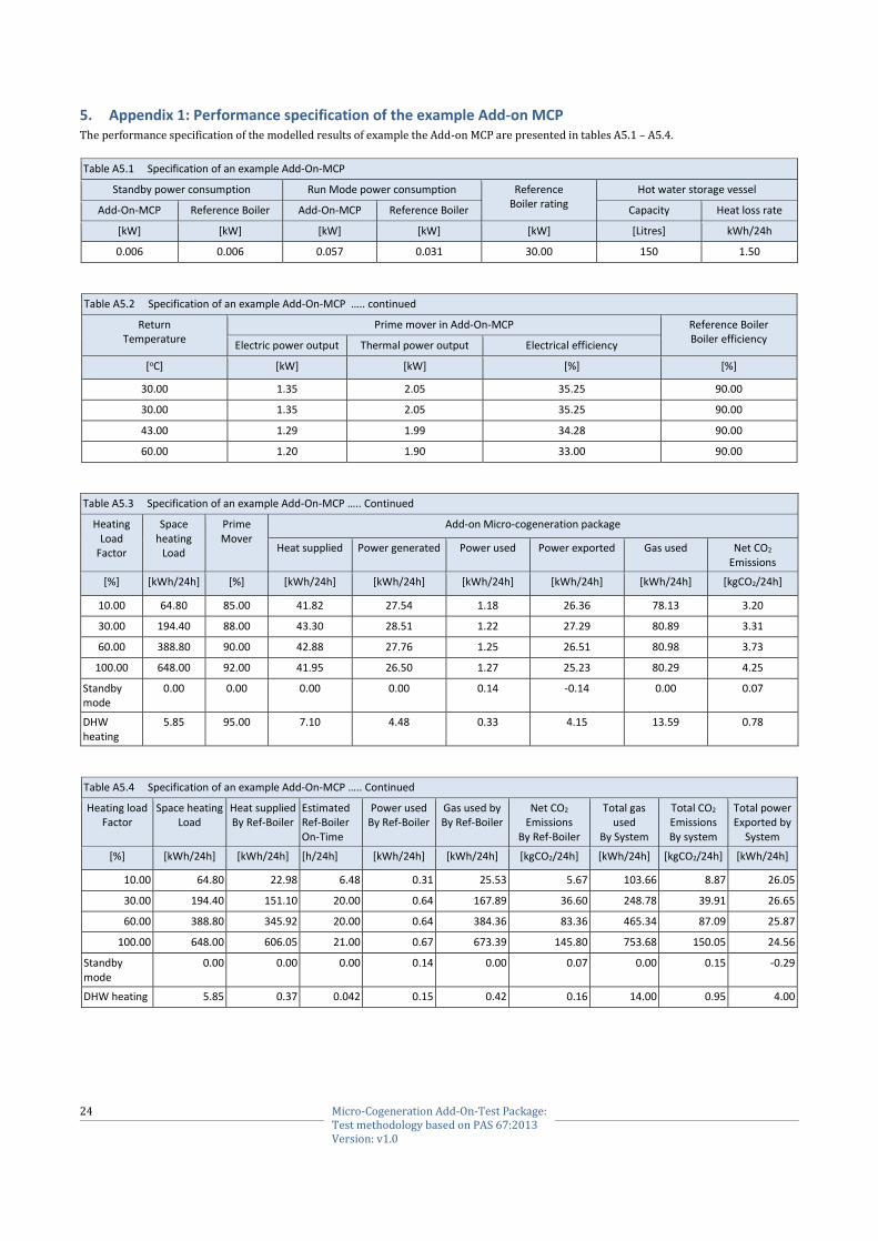
24 Micro-Cogeneration Add-On-Test Package: Test methodology based on PAS 67:2013 Version: v1.0
5. Appendix 1: Performance specification of the example Add-on MCP The performance specification of the modelled results of example the Add-on MCP are presented in tables A5.1 – A5.4.
Table A5.1 Specification of an example Add-On-MCP
Standby power consumption Run Mode power consumption Reference Boiler rating
Hot water storage vessel
Add-On-MCP Reference Boiler Add-On-MCP Reference Boiler Capacity Heat loss rate
[kW] [kW] [kW] [kW] [kW] [Litres] kWh/24h
0.006 0.006 0.057 0.031 30.00 150 1.50
Table A5.2 Specification of an example Add-On-MCP ….. continued
Return Temperature
Prime mover in Add-On-MCP Reference Boiler Boiler efficiency
Electric power output Thermal power output Electrical efficiency
[oC] [kW] [kW] [%] [%]
30.00 1.35 2.05 35.25 90.00
30.00 1.35 2.05 35.25 90.00
43.00 1.29 1.99 34.28 90.00
60.00 1.20 1.90 33.00 90.00
Table A5.3 Specification of an example Add-On-MCP ….. Continued
Heating Load
Factor
Space heating
Load
Prime Mover
Add-on Micro-cogeneration package
Heat supplied
Power generated
Power used
Power exported
Gas used
Net CO2 Emissions
[%] [kWh/24h] [%] [kWh/24h] [kWh/24h] [kWh/24h] [kWh/24h] [kWh/24h] [kgCO2/24h]
10.00 64.80 85.00 41.82 27.54 1.18 26.36 78.13 3.20
30.00 194.40 88.00 43.30 28.51 1.22 27.29 80.89 3.31
60.00 388.80 90.00 42.88 27.76 1.25 26.51 80.98 3.73
100.00 648.00 92.00 41.95 26.50 1.27 25.23 80.29 4.25
Standby mode
0.00 0.00 0.00 0.00 0.14 -0.14 0.00 0.07
DHW heating
5.85 95.00 7.10 4.48 0.33 4.15 13.59 0.78
Table A5.4 Specification of an example Add-On-MCP ….. Continued
Heating load Factor
Space heating Load
Heat supplied By Ref-Boiler
Estimated Ref-Boiler On-Time
Power used By Ref-Boiler
Gas used by By Ref-Boiler
Net CO2 Emissions
By Ref-Boiler
Total gas used
By System
Total CO2 Emissions By system
Total power Exported by
System
[%] [kWh/24h] [kWh/24h] [h/24h] [kWh/24h] [kWh/24h] [kgCO2/24h] [kWh/24h] [kgCO2/24h] [kWh/24h]
10.00 64.80 22.98 6.48 0.31 25.53 5.67 103.66 8.87 26.05
30.00 194.40 151.10 20.00 0.64 167.89 36.60 248.78 39.91 26.65
60.00 388.80 345.92 20.00 0.64 384.36 83.36 465.34 87.09 25.87
100.00 648.00 606.05 21.00 0.67 673.39 145.80 753.68 150.05 24.56
Standby mode
0.00 0.00 0.00 0.14 0.00 0.07 0.00 0.15 -0.29
DHW heating 5.85 0.37 0.042 0.15 0.42 0.16 14.00 0.95 4.00
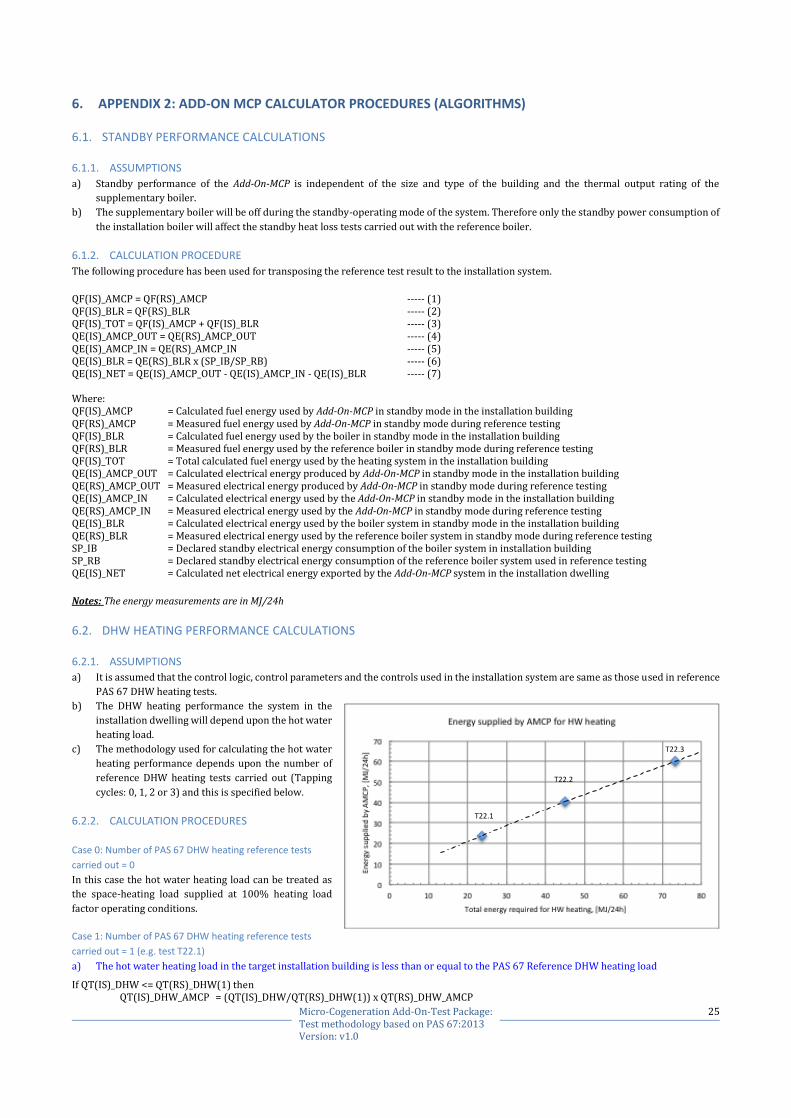
25 Micro-Cogeneration Add-On-Test Package: Test methodology based on PAS 67:2013 Version: v1.0
6. APPENDIX 2: ADD-ON MCP CALCULATOR PROCEDURES (ALGORITHMS)
6.1. STANDBY PERFORMANCE CALCULATIONS
6.1.1. ASSUMPTIONS
a) Standby performance of the Add-On-MCP is independent of the size and type of the building and the thermal output rating of the
supplementary boiler.
b) The supplementary boiler will be off during the standby-operating mode of the system. Therefore only the standby power consumption of
the installation boiler will affect the standby heat loss tests carried out with the reference boiler.
6.1.2. CALCULATION PROCEDURE
The following procedure has been used for transposing the reference test result to the installation system.
QF(IS)_AMCP = QF(RS)_AMCP ----- (1) QF(IS)_BLR = QF(RS)_BLR ----- (2) QF(IS)_TOT = QF(IS)_AMCP + QF(IS)_BLR ----- (3) QE(IS)_AMCP_OUT = QE(RS)_AMCP_OUT ----- (4) QE(IS)_AMCP_IN = QE(RS)_AMCP_IN ----- (5) QE(IS)_BLR = QE(RS)_BLR x (SP_IB/SP_RB) ----- (6) QE(IS)_NET = QE(IS)_AMCP_OUT - QE(IS)_AMCP_IN - QE(IS)_BLR ----- (7) Where: QF(IS)_AMCP = Calculated fuel energy used by Add-On-MCP in standby mode in the installation building QF(RS)_AMCP = Measured fuel energy used by Add-On-MCP in standby mode during reference testing QF(IS)_BLR = Calculated fuel energy used by the boiler in standby mode in the installation building QF(RS)_BLR = Measured fuel energy used by the reference boiler in standby mode during reference testing QF(IS)_TOT = Total calculated fuel energy used by the heating system in the installation building QE(IS)_AMCP_OUT = Calculated electrical energy produced by Add-On-MCP in standby mode in the installation building QE(RS)_AMCP_OUT = Measured electrical energy produced by Add-On-MCP in standby mode during reference testing QE(IS)_AMCP_IN = Calculated electrical energy used by the Add-On-MCP in standby mode in the installation building QE(RS)_AMCP_IN = Measured electrical energy used by the Add-On-MCP in standby mode during reference testing QE(IS)_BLR = Calculated electrical energy used by the boiler system in standby mode in the installation building QE(RS)_BLR = Measured electrical energy used by the reference boiler system in standby mode during reference testing SP_IB = Declared standby electrical energy consumption of the boiler system in installation building SP_RB = Declared standby electrical energy consumption of the reference boiler system used in reference testing QE(IS)_NET = Calculated net electrical energy exported by the Add-On-MCP system in the installation dwelling
Notes: The energy measurements are in MJ/24h
6.2. DHW HEATING PERFORMANCE CALCULATIONS
6.2.1. ASSUMPTIONS
a) It is assumed that the control logic, control parameters and the controls used in the installation system are same as those used in reference
PAS 67 DHW heating tests.
b) The DHW heating performance the system in the
installation dwelling will depend upon the hot water
heating load.
c) The methodology used for calculating the hot water
heating performance depends upon the number of
reference DHW heating tests carried out (Tapping
cycles: 0, 1, 2 or 3) and this is specified below.
6.2.2. CALCULATION PROCEDURES
Case 0: Number of PAS 67 DHW heating reference tests
carried out = 0
In this case the hot water heating load can be treated as
the space-heating load supplied at 100% heating load
factor operating conditions.
Case 1: Number of PAS 67 DHW heating reference tests
carried out = 1 (e.g. test T22.1)
a) The hot water heating load in the target installation building is less than or equal to the PAS 67 Reference DHW heating load
If QT(IS)_DHW <= QT(RS)_DHW(1) then QT(IS)_DHW_AMCP = (QT(IS)_DHW/QT(RS)_DHW(1)) x QT(RS)_DHW_AMCP
T22.1
T22.2
T22.3

26 Micro-Cogeneration Add-On-Test Package: Test methodology based on PAS 67:2013 Version: v1.0
QT(IS)_DHW_BLR = QT(IS)_DHW - QT(IS)_DHW_AMCP End IF b) The hot water heating load in the target installation building is greater than the PAS 67 Reference DHW heating load
If QT(IS)_DHW > QT(RS)_DHW(1) then QT(IS)_DHW_AMCP = QT(RS)_DHW(2) QT(IS)_DHW_BLR = QT(IS)_DHW - QT(IS)_DHW_AMCP
End IF c) Applies to both (a) and (b)
R1 = QT(IS)_DHW_AMCP / QT(RS)_DHW_AMCP ERATIO_BLR = DE_IBLR / DE_RBLR ET(IBLR)_SYSTEM = ERATIO_BLR x E(RBLR)_SYSTEM(1) ET(IS)_AMCP = ET(RS)_AMCP(1) EE(IS)_AMCP = EE(RS)_AMCP(1) QF(IS)_AMCP = QT(IS)_DHW_AMCP x 100 / ET(IS)_AMCP QF(IS)_BLR = QT(IS)_DHW_BLR x 100 / ET(IBLR)_SYSTEM QF(IS)_TOT = QF(IS)_AMCP + QF(IS)_BLR QE(IS)_AMCP_OUT = QF(IS)_AMCP x EE(RS)_AMCP(1) QE(IS)_AMCP_IN = (1/R1) x QE(RS)_AMCP_IN QE(IS)_BLR_IN = QE(RS)_BLR_IN x (SP_IB/SP_RB) QE(IS)_NET = QE(IS)_AMCP_OUT - [QE(IS)_AMCP_IN + QE(IS)_BLR_IN]
Case 2: No PAS 67 DHW heating reference tests carried out = 2 (e.g. tests T22.1 and T22.2)
a) The hot water heating load in the target installation building is less than or equal to the PAS 67 Reference DHW heating load in test T22.1.
If QT(IS)_DHW <= QT(RS)_DHW(1) then QT(IS)_DHW_AMCP = (QT(IS)_DHW(1)/QT(RS)_DHW(1)) x QT(RS)_DHW_AMCP(1) QT(IS)_DHW_BLR = QT(IS)_DHW - QT(IS)_DHW_AMCP R1 = QT(IS)_DHW_AMCP / QT(RS)_DHW_AMCP ERATIO_BLR = DE_IBLR / DE_RBLR ET(IBLR)_SYSTEM = ERATIO_BLR x E(RBLR)_SYSTEM(1) ET(IS)_AMCP = ET(RS)_AMCP(1) EE(IS)_AMCP = EE(RS)_AMCP(1)
End IF b) The hot water heating load in the target installation building is greater than the PAS 67 Reference DHW heating load in test T22.2.
If QT(IS)_DHW > QT(RS)_DHW(2) then QT(IS)_DHW_AMCP = QT(RS)_DHW(2) QT(IS)_DHW_BLR = QT(IS)_DHW - QT(IS)_DHW_AMCP R1 = QT(IS)_DHW_AMCP / QT(RS)_DHW_AMCP ERATIO_BLR = DE_IBLR / DE_RBLR ET(IBLR)_SYSTEM = ERATIO_BLR x E(RBLR)_SYSTEM(2) ET(IS)_AMCP = ET(RS)_AMCP(2) EE(IS)_AMCP = EE(RS)_AMCP(2)
End IF c) The hot water heating load in the target installation building is between the PAS 67 Reference DHW heating load in tests T22.1 and
T22.2.
If [QT(IS)_DHW > QT(RS)_DHW(1)] AND [QT(IS)_DHW < QT(RS)_DHW(2)] then Slope = [QT(RS)_DHW_AMCP(2) - QT(RS)_DHW_AMCP(1)] / [QT(RS)_DHW(2) - QT(RS_DHW(1)] X1 = QT(IS)_DHW - QT(RS)_DHW(1) QT(IS)_DHW_AMCP =QT(RS)_DHW_AMCP(1) + (X1 x Slope) QT(IS)_DHW_BLR = QT(IS)_DHW - QT(IS)_DHW_AMCP R1 = QT(IS)_DHW_AMCP / QT(RS)_DHW_AMCP ERATIO_BLR = DE_IBLR / DE_RBLR ET(IBLR)_SYSTEM = ERATIO_BLR x [(E(RBLR)_SYSTEM(1) + E(RBLR)_SYSTEM(2))/2] ET(IS)_AMCP = (ET(RS)_AMCP(1) + ET(RS)_AMCP(2))/2 EE(IS)_AMCP = (EE(RS)_AMCP(1) + EE(RS)_AMCP(2))/2
End IF d) Applies to (a), (b) and (c)
QF(IS)_AMCP = QT(IS)_DHW_AMCP x 100 / ET(IS)_AMCP QF(IS)_BLR = QT(IS)_DHW_BLR x 100 / ET(IBLR)_SYSTEM QF(IS)_TOT = QF(IS)_AMCP + QF(IS)_BLR QE(IS)_AMCP_OUT = QF(IS)_AMCP x EE(IS)_AMCP QE(IS)_AMCP_IN = (1/R1) x QE(RS)_AMCP_IN QE(IS)_BLR_IN = QE(RS)_BLR_IN x (SP_IB/SP_RB)
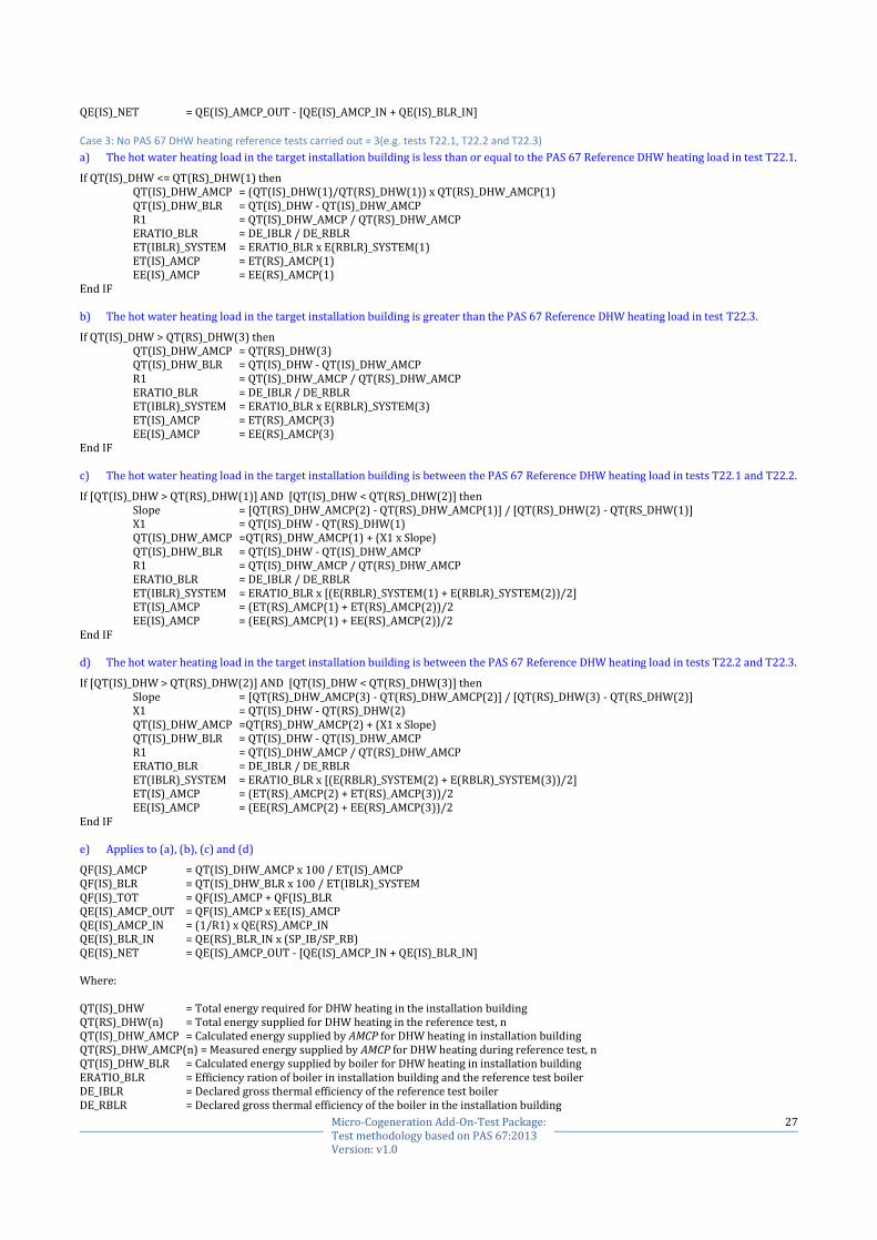
27 Micro-Cogeneration Add-On-Test Package: Test methodology based on PAS 67:2013 Version: v1.0
QE(IS)_NET = QE(IS)_AMCP_OUT - [QE(IS)_AMCP_IN + QE(IS)_BLR_IN]
Case 3: No PAS 67 DHW heating reference tests carried out = 3(e.g. tests T22.1, T22.2 and T22.3)
a) The hot water heating load in the target installation building is less than or equal to the PAS 67 Reference DHW heating load in test T22.1.
If QT(IS)_DHW <= QT(RS)_DHW(1) then QT(IS)_DHW_AMCP = (QT(IS)_DHW(1)/QT(RS)_DHW(1)) x QT(RS)_DHW_AMCP(1) QT(IS)_DHW_BLR = QT(IS)_DHW - QT(IS)_DHW_AMCP R1 = QT(IS)_DHW_AMCP / QT(RS)_DHW_AMCP ERATIO_BLR = DE_IBLR / DE_RBLR ET(IBLR)_SYSTEM = ERATIO_BLR x E(RBLR)_SYSTEM(1) ET(IS)_AMCP = ET(RS)_AMCP(1) EE(IS)_AMCP = EE(RS)_AMCP(1)
End IF b) The hot water heating load in the target installation building is greater than the PAS 67 Reference DHW heating load in test T22.3.
If QT(IS)_DHW > QT(RS)_DHW(3) then QT(IS)_DHW_AMCP = QT(RS)_DHW(3) QT(IS)_DHW_BLR = QT(IS)_DHW - QT(IS)_DHW_AMCP R1 = QT(IS)_DHW_AMCP / QT(RS)_DHW_AMCP ERATIO_BLR = DE_IBLR / DE_RBLR ET(IBLR)_SYSTEM = ERATIO_BLR x E(RBLR)_SYSTEM(3) ET(IS)_AMCP = ET(RS)_AMCP(3) EE(IS)_AMCP = EE(RS)_AMCP(3)
End IF c) The hot water heating load in the target installation building is between the PAS 67 Reference DHW heating load in tests T22.1 and T22.2.
If [QT(IS)_DHW > QT(RS)_DHW(1)] AND [QT(IS)_DHW < QT(RS)_DHW(2)] then Slope = [QT(RS)_DHW_AMCP(2) - QT(RS)_DHW_AMCP(1)] / [QT(RS)_DHW(2) - QT(RS_DHW(1)] X1 = QT(IS)_DHW - QT(RS)_DHW(1) QT(IS)_DHW_AMCP =QT(RS)_DHW_AMCP(1) + (X1 x Slope) QT(IS)_DHW_BLR = QT(IS)_DHW - QT(IS)_DHW_AMCP R1 = QT(IS)_DHW_AMCP / QT(RS)_DHW_AMCP ERATIO_BLR = DE_IBLR / DE_RBLR ET(IBLR)_SYSTEM = ERATIO_BLR x [(E(RBLR)_SYSTEM(1) + E(RBLR)_SYSTEM(2))/2] ET(IS)_AMCP = (ET(RS)_AMCP(1) + ET(RS)_AMCP(2))/2 EE(IS)_AMCP = (EE(RS)_AMCP(1) + EE(RS)_AMCP(2))/2
End IF d) The hot water heating load in the target installation building is between the PAS 67 Reference DHW heating load in tests T22.2 and T22.3.
If [QT(IS)_DHW > QT(RS)_DHW(2)] AND [QT(IS)_DHW < QT(RS)_DHW(3)] then Slope = [QT(RS)_DHW_AMCP(3) - QT(RS)_DHW_AMCP(2)] / [QT(RS)_DHW(3) - QT(RS_DHW(2)] X1 = QT(IS)_DHW - QT(RS)_DHW(2) QT(IS)_DHW_AMCP =QT(RS)_DHW_AMCP(2) + (X1 x Slope) QT(IS)_DHW_BLR = QT(IS)_DHW - QT(IS)_DHW_AMCP R1 = QT(IS)_DHW_AMCP / QT(RS)_DHW_AMCP ERATIO_BLR = DE_IBLR / DE_RBLR ET(IBLR)_SYSTEM = ERATIO_BLR x [(E(RBLR)_SYSTEM(2) + E(RBLR)_SYSTEM(3))/2] ET(IS)_AMCP = (ET(RS)_AMCP(2) + ET(RS)_AMCP(3))/2 EE(IS)_AMCP = (EE(RS)_AMCP(2) + EE(RS)_AMCP(3))/2
End IF e) Applies to (a), (b), (c) and (d)
QF(IS)_AMCP = QT(IS)_DHW_AMCP x 100 / ET(IS)_AMCP QF(IS)_BLR = QT(IS)_DHW_BLR x 100 / ET(IBLR)_SYSTEM QF(IS)_TOT = QF(IS)_AMCP + QF(IS)_BLR QE(IS)_AMCP_OUT = QF(IS)_AMCP x EE(IS)_AMCP QE(IS)_AMCP_IN = (1/R1) x QE(RS)_AMCP_IN QE(IS)_BLR_IN = QE(RS)_BLR_IN x (SP_IB/SP_RB) QE(IS)_NET = QE(IS)_AMCP_OUT - [QE(IS)_AMCP_IN + QE(IS)_BLR_IN] Where: QT(IS)_DHW = Total energy required for DHW heating in the installation building QT(RS)_DHW(n) = Total energy supplied for DHW heating in the reference test, n QT(IS)_DHW_AMCP = Calculated energy supplied by AMCP for DHW heating in installation building QT(RS)_DHW_AMCP(n) = Measured energy supplied by AMCP for DHW heating during reference test, n QT(IS)_DHW_BLR = Calculated energy supplied by boiler for DHW heating in installation building ERATIO_BLR = Efficiency ration of boiler in installation building and the reference test boiler DE_IBLR = Declared gross thermal efficiency of the reference test boiler DE_RBLR = Declared gross thermal efficiency of the boiler in the installation building
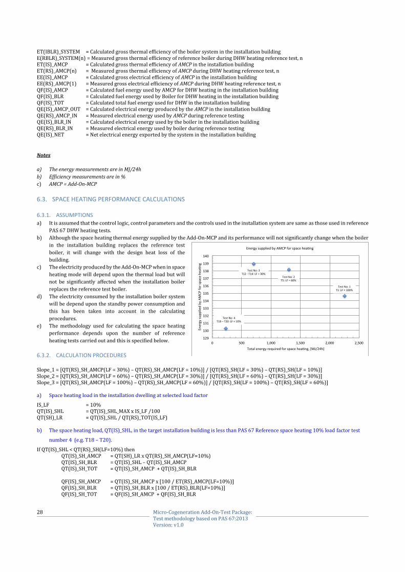
28 Micro-Cogeneration Add-On-Test Package: Test methodology based on PAS 67:2013 Version: v1.0
ET(IBLR)_SYSTEM = Calculated gross thermal efficiency of the boiler system in the installation building E(RBLR)_SYSTEM(n) = Measured gross thermal efficiency of reference boiler during DHW heating reference test, n ET(IS)_AMCP = Calculated gross thermal efficiency of AMCP in the installation building ET(RS)_AMCP(n) = Measured gross thermal efficiency of AMCP during DHW heating reference test, n EE(IS)_AMCP = Calculated gross electrical efficiency of AMCP in the installation building EE(RS)_AMCP(1) = Measured gross electrical efficiency of AMCP during DHW heating reference test, n QF(IS)_AMCP = Calculated fuel energy used by AMCP for DHW heating in the installation building QF(IS)_BLR = Calculated fuel energy used by Boiler for DHW heating in the installation building QF(IS)_TOT = Calculated total fuel energy used for DHW in the installation building QE(IS)_AMCP_OUT = Calculated electrical energy produced by the AMCP in the installation building QE(RS)_AMCP_IN = Measured electrical energy used by AMCP during reference testing QE(IS)_BLR_IN = Calculated electrical energy used by the boiler in the installation building QE(RS)_BLR_IN = Measured electrical energy used by boiler during reference testing QE(IS)_NET = Net electrical energy exported by the system in the installation building
Notes
a) The energy measurements are in MJ/24h
b) Efficiency measurements are in %
c) AMCP = Add-On-MCP
6.3. SPACE HEATING PERFORMANCE CALCULATIONS
6.3.1. ASSUMPTIONS
a) It is assumed that the control logic, control parameters and the controls used in the installation system are same as those used in reference
PAS 67 DHW heating tests.
b) Although the space heating thermal energy supplied by the Add-On-MCP and its performance will not significantly change when the boiler
in the installation building replaces the reference test
boiler, it will change with the design heat loss of the
building.
c) The electricity produced by the Add-On-MCP when in space
heating mode will depend upon the thermal load but will
not be significantly affected when the installation boiler
replaces the reference test boiler.
d) The electricity consumed by the installation boiler system
will be depend upon the standby power consumption and
this has been taken into account in the calculating
procedures.
e) The methodology used for calculating the space heating
performance depends upon the number of reference
heating tests carried out and this is specified below.
6.3.2. CALCULATION PROCEDURES
Slope_1 = [QT(RS)_SH_AMCP(LF = 30%) – QT(RS)_SH_AMCP(LF = 10%)] / [QT(RS)_SH(LF = 30%) – QT(RS)_SH(LF = 10%)] Slope_2 = [QT(RS)_SH_AMCP(LF = 60%) – QT(RS)_SH_AMCP(LF = 30%)] / [QT(RS)_SH(LF = 60%) – QT(RS)_SH(LF = 30%)] Slope_3 = [QT(RS)_SH_AMCP(LF = 100%) – QT(RS)_SH_AMCP(LF = 60%)] / [QT(RS)_SH(LF = 100%) – QT(RS)_SH(LF = 60%)] a) Space heating load in the installation dwelling at selected load factor
IS_LF = 10% QT(IS)_SHL = QT(IS)_SHL_MAX x IS_LF /100 QT(SH)_LR = QT(IS)_SHL / QT(RS)_TOT(IS_LF) b) The space heating load, QT(IS)_SHL, in the target installation building is less than PAS 67 Reference space heating 10% load factor test
number 4 (e.g. T18 – T20).
If QT(IS)_SHL < QT(RS)_SH(LF=10%) then QT(IS)_SH_AMCP = QT(SH)_LR x QT(RS)_SH_AMCP(LF=10%) QT(IS)_SH_BLR = QT(IS)_SHL – QT(IS)_SH_AMCP QT(IS)_SH_TOT = QT(IS)_SH_AMCP + QT(IS)_SH_BLR QF(IS)_SH_AMCP = QT(IS)_SH_AMCP x [100 / ET(RS)_AMCP(LF=10%)] QF(IS)_SH_BLR = QT(IS)_SH_BLR x [100 / ET(RS)_BLR(LF=10%)] QF(IS)_SH_TOT = QF(IS)_SH_AMCP + QF(IS)_SH_BLR
TestNo:1T1:LF=100%
TestNo:2T5:LF=60%
TestNo:3T12-T14:LF=30%
TestNo:4T18–T20:LF=10%

29 Micro-Cogeneration Add-On-Test Package: Test methodology based on PAS 67:2013 Version: v1.0
QE(IS)_AMP_OUT = QF(IS)_AMCP x [100 / EE(RS)_AMCP(LF=10%)] QE(IS)_AMCP_IN = QE(IS)_AMCP_IN(LF=10%) x [1 / QT(SH)_LR] QE(IS)_BLR = QE(RS)_BLR(LF=10%) x QT(SH)_LR QE(IS)_NET = QE(IS)_AMP_OUT – [QE(IS)_AMCP_IN + QE(IS)_BLR] ET(IS)_AMCP = QT(IS)_SH_AMCP x [100 / QF(IS)_SH_AMCP] EE(IS)_AMCP = QE(IS)_AMP_OUT x [100 / QF(IS)_SH_AMCP] ET(IS)_BLR = QT(IS)_BLR x [100 / QF(IS)_BLR
End IF c) The space heating load, QT(IS)_SHL, is between the 10% heating load factor test (No 4) AND 30% heating load factor test (No 3).
If QT(IS)_SHL >= QT(RS)_SH(LF = 10%) AND QT(IS)_SHL < QT(RS)_SH(LF = 30%) then X1 = QT(IS)_SHL – QT(RS)_SH(LF = 10%)
QT(IS)_SH_AMCP = QT(RS)_SH_AMCP(LF = 10%) + (X1 x Slope_1) QT(IS)_SH_BLR = QT(IS)_SHL – QT(IS)_SH_AMCP QT(IS)_SH_TOT = QT(IS)_SH_AMCP + QT(IS)_SH_BLR QF(IS)_SH_AMCP = QT(IS)_SH_AMCP x [100 / ((ET(RS)_AMCP(LF = 10%) + ET(RS)_AMCP(KF = 30%))/2)] QF(IS)_SH_BLR = QT(IS)_SH_BLR x [100 / ((ET(RS)_BLR(LF = 10%) + ET(RS)_BLR(LF = 30%))/2)] QF(IS)_SH_TOT = QF(IS)_SH_AMCP + QF(IS)_SH_BLR QE(IS)_AMP_OUT = QF(IS)_AMCP x [100 / ((EE(RS)_AMCP(LF = 10%) + EE(RS)_AMCP(LF = 10%))/2)] QE(IS)_AMCP_IN = ((QE(IS)_AMCP_IN(LF = 10%) + QE(IS)_AMCP_IN(LF = 30%))/2) x [1 / QT(SH)_LR] QE(IS)_BLR = ((QE(RS)_BLR(LF = 10%) + QE(RS)_BLR(LF = 30%))/2) x QT(SH)_LR QE(IS)_NET = QE(IS)_AMP_OUT – [QE(IS)_AMCP_IN + QE(IS)_BLR] ET(IS)_AMCP = QT(IS)_SH_AMCP x [100 / QF(IS)_SH_AMCP] EE(IS)_AMCP = QE(IS)_AMP_OUT x [100 / QF(IS)_SH_AMCP] ET(IS)_BLR = QT(IS)_BLR x [100 / QF(IS)_BLR
End IF d) The space heating load, QT(IS)_SHL, is between the 30% heating load factor test (No 3) AND 60% heating load factor test (No 2).
If QT(IS)_SHL >= QT(RS)_SH(LF = 30%) AND QT(IS)_SHL < QT(RS)_SH(LF = 60%) then X1 = QT(IS)_SHL – QT(RS)_SH(LF = 30%)
QT(IS)_SH_AMCP = QT(RS)_SH_AMCP(LF = 30%) + (X1 x Slope_2) QT(IS)_SH_BLR = QT(IS)_SHL – QT(IS)_SH_AMCP QT(IS)_SH_TOT = QT(IS)_SH_AMCP + QT(IS)_SH_BLR QF(IS)_SH_AMCP = QT(IS)_SH_AMCP x [100 / ((ET(RS)_AMCP(LF = 30%) + ET(RS)_AMCP(KF = 60%))/2)] QF(IS)_SH_BLR = QT(IS)_SH_BLR x [100 / ((ET(RS)_BLR(LF = 30%) + ET(RS)_BLR(LF = 60%))/2)] QF(IS)_SH_TOT = QF(IS)_SH_AMCP + QF(IS)_SH_BLR QE(IS)_AMP_OUT = QF(IS)_AMCP x [100 / ((EE(RS)_AMCP(LF = 30%) + EE(RS)_AMCP(LF = 60%))/2)] QE(IS)_AMCP_IN = ((QE(IS)_AMCP_IN(LF = 30%) + QE(IS)_AMCP_IN(LF = 60%))/2) x [1 / QT(SH)_LR] QE(IS)_BLR = ((QE(RS)_BLR(LF = 30%) + QE(RS)_BLR(LF = 60%))/2) x QT(SH)_LR QE(IS)_NET = QE(IS)_AMP_OUT – [QE(IS)_AMCP_IN + QE(IS)_BLR] ET(IS)_AMCP = QT(IS)_SH_AMCP x [100 / QF(IS)_SH_AMCP] EE(IS)_AMCP = QE(IS)_AMP_OUT x [100 / QF(IS)_SH_AMCP] ET(IS)_BLR = QT(IS)_BLR x [100 / QF(IS)_BLR
End IF e) The space heating load, QT(IS)_SHL, is between the 60% heating load factor test (No 2) AND 100% heating load factor test (No 1).
If QT(IS)_SHL >= QT(RS)_SH(LF = 60%) AND QT(IS)_SHL < QT(RS)_SH(LF = 100%) then X1 = QT(IS)_SHL – QT(RS)_SH(LF = 60%)
QT(IS)_SH_AMCP = QT(RS)_SH_AMCP(LF = 30%) + (X1 x Slope_3) QT(IS)_SH_BLR = QT(IS)_SHL – QT(IS)_SH_AMCP QT(IS)_SH_TOT = QT(IS)_SH_AMCP + QT(IS)_SH_BLR QF(IS)_SH_AMCP = QT(IS)_SH_AMCP x [100 / ((ET(RS)_AMCP(LF = 60%) + ET(RS)_AMCP(KF = 100%))/2)] QF(IS)_SH_BLR = QT(IS)_SH_BLR x [100 / ((ET(RS)_BLR(LF = 60%) + ET(RS)_BLR(LF = 100%))/2)] QF(IS)_SH_TOT = QF(IS)_SH_AMCP + QF(IS)_SH_BLR QE(IS)_AMP_OUT = QF(IS)_AMCP x [100 / ((EE(RS)_AMCP(LF = 60%) + EE(RS)_AMCP(LF = 100%))/2)] QE(IS)_AMCP_IN = ((QE(IS)_AMCP_IN(LF = 60%) + QE(IS)_AMCP_IN(LF = 100%))/2) x [1 / QT(SH)_LR] QE(IS)_BLR = ((QE(RS)_BLR(LF = 60%) + QE(RS)_BLR(LF = 100%))/2) x QT(SH)_LR QE(IS)_NET = QE(IS)_AMP_OUT – [QE(IS)_AMCP_IN + QE(IS)_BLR] ET(IS)_AMCP = QT(IS)_SH_AMCP x [100 / QF(IS)_SH_AMCP] EE(IS)_AMCP = QE(IS)_AMP_OUT x [100 / QF(IS)_SH_AMCP] ET(IS)_BLR = QT(IS)_BLR x [100 / QF(IS)_BLR
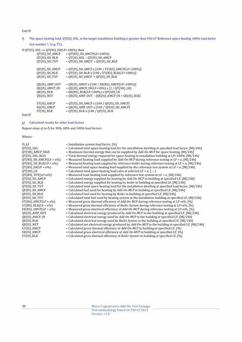
30 Micro-Cogeneration Add-On-Test Package: Test methodology based on PAS 67:2013 Version: v1.0
End IF f) The space heating load, QT(IS)_SHL, in the target installation building is greater than PAS 67 Reference space heating 100% load factor
test number 1 (e.g. T1).
If QT(IS)_SHL >= QT(RS)_SH(LF=100%) then QT(IS)_SH_AMCP = QT(RS)_SH_AMCP(LF=100%) QT(IS)_SH_BLR = QT(IS)_SHL – QT(IS)_SH_AMCP QT(IS)_SH_TOT = QT(IS)_SH_AMCP + QT(IS)_SH_BLR QF(IS)_SH_AMCP = QT(IS)_SH_AMCP x [100 / ET(RS)_AMCP(LF=100%)] QF(IS)_SH_BLR = QT(IS)_SH_BLR x [100 / ET(RS)_BLR(LF=100%)] QF(IS)_SH_TOT = QF(IS)_SH_AMCP + QF(IS)_SH_BLR QE(IS)_AMP_OUT = QF(IS)_AMCP x [100 / EE(RS)_AMCP(LF=100%)] QE(IS)_AMCP_IN = QE(IS)_AMCP_IN(LF=10%) x [1 / QT(SH)_LR] QE(IS)_BLR = QE(RS)_BLR(LF=100%) x QT(SH)_LR QE(IS)_NET = QE(IS)_AMP_OUT – [QE(IS)_AMCP_IN + QE(IS)_BLR] ET(IS)_AMCP = QT(IS)_SH_AMCP x [100 / QF(IS)_SH_AMCP] EE(IS)_AMCP = QE(IS)_AMP_OUT x [100 / QF(IS)_SH_AMCP] ET(IS)_BLR = QT(IS)_BLR x [100 / QF(IS)_BLR
End IF g) Calculated results for other load factors
Repeat steps a) to f) for 30%, 60% and 100% load factors
Where: - IS_LF = Installation system load factor, [%] QT(IS)_SHL = Calculated total space heating load for the installation dwelling at specified load factor, [MJ/24h] QT(SH)_AMCP_MAX = Maximum thermal energy that can be supplied by Add-On-MCP for space heating, [MJ/24h] QT(IS)_SHL_MAX = Total thermal energy required for space heating in installation building at LF=100%, [MJ/24h] QT(RS)_SH_AMCP(LF = n%) = Measured heating load supplied by Add-On-MCP during reference testing at LF = n, [MJ/24h] QT(RS)_SH_BLR(LF = n%) = Measured heating load supplied by reference boiler during reference testing at LF = n, [MJ/24h] QT(RS)_SH(LF = n%) = Measured total space heating load supplied by the reference test system at LF = n, [MJ/24h] QT(SH)_LR = Calculated total space heating load ratio at selected LF = n, [ -- ] QT(RS)_TOT(LF=n%) = Measured total heating load supplied by reference test system at LF = n, [MJ/24h] QT(IS)_SH_AMCP = Calculated energy supplied for heating by Add-On-MCP in building at specified LF, [MJ/24h] QT(IS)_SH_BLR = Calculated energy supplied for heating by boiler in building at specified LF, [MJ/24h] QT(IS)_SH_TOT = Calculated total space heating load for the installation dwelling at specified load factor, [MJ/24h] QF(IS)_SH_AMCP = Calculated fuel used for heating by Add-On-MCP in building at specified LF, [MJ/24h] QF(IS)_SH_BLR = Calculated fuel used for heating by Boiler in building at specified LF, [MJ/24h] QF(IS)_SH_TOT = Calculated total fuel used by heating system in the installation building at specified LF, [MJ/24h] ET(RS)_AMCP(LF = n%) = Measured gross thermal efficiency of Add-On-MCP during reference testing at LF=n%, [%] ET(RS)_BLR(LF = n%) = Measured gross thermal efficiency of Boiler System during reference testing at LF=n%, [%] EE(RS)_AMCP(LF = n%) = Measured gross electrical efficiency of Add-On-MCP during reference testing at LF=n%, [%] QE(IS)_AMP_OUT = Calculated electrical energy produced by Add-On-MCP in the building at specified LF, [MJ/24h] QE(IS)_AMCP_IN = Calculated electrical energy used by Add-On-MCP in the building at specified LF, [MJ/24h] QE(IS)_BLR = Calculated electrical energy used by Boiler System in the building at specified LF, [MJ/24h] QE(IS)_NET = Calculated net electrical energy produced by Add-On-MCP in the building at specified LF, [MJ/24h] ET(IS)_AMCP = Calculated gross thermal efficiency of Add-On-MCP in building at specified LF, [%] EE(IS)_AMCP = Calculated gross electrical efficiency of Add-On-MCP in building at specified LF, [%] ET(IS)_BLR = Calculated gross thermal efficiency of Boiler System in building at specified LF, [%]
Related Documents