MCS-012 CO&ALP -1- Loganathan R Bangalore Question 1 a) Perform the following arithmetic operations using binary signed 2’s complement notation for integers. You may assume that the maximum size of integers is of 12 bits including the sign bit. i) Add – 512 and 198 ii) Subtract 400 from – 98 iii) Add 400 and 112 Ans: i) 512 in Binary = 10 0000 0000 2s comp of 512(i.e -512) = 10 0000 0000 198 in Binary = + 00 1100 0110 Addition = Cy 10 1100 0110 Since no Carry the result is in 2’s compliment form so sign is –ve and magnitude is 2s compliment of result 10 1100 0110 is 01 0011 1010(314) = -314 No Overflow since Cin to Sign bit & Cout from Sign bit are same. ii) 98 in Binary = 00 0110 0010 2s comp of 98 (ie -98) = 11 1001 1110 2s comp of 400(i.e -400) Addition = + 10 0111 0000 = Cy 10 0000 1110 Since Carry is 1, discard the carry and the result is –ve, the magnitude is 2’s compliment of the result 10 0000 1110 = 01 1111 0010 = -498 No Overflow since Cin to Sign bit & Cout from Sign bit is same. iii) 400 in Binary = 01 1001 0000 112 in Binary Addition = + 00 0111 0000 = Cy 10 0000 0000 There is No Overflow, since Cin is to Sign bit & Cout is from Sign bit are same. The result is correct b) Convert the hexadecimal number: 21 3A EF into binary, octal and decimal equivalent. Ans: Binary = 0010 0001 0011 1010 1110 1111 Octal = 10235357 Decimal = 2177775 c) Convert the following string into equivalent “UTF 16” code –“Email addresses always use @ sign”. Are these codes same as that used in ASCII? Ans: UTF-16 Code: 0045 006D 0061 0069 006C 0020 0061 0064 0064 0072 0065 0073 0073 0065 0073 0020 0061 006C 0077 0061 0079 0073 0020 0075 0073 0065 0020 0040 0020 0073 0069 0067 006E ASCII Code: 45 6D 61 69 6C 20 61 64 64 72 65 73 73 65 73 20 61 6C 77 61 79 73 20 75 73 65 20 40 20 73 69 67 6E No, these codes are NOT the same. (UTF 16 is 16 bit but ASCII is 8 bit)

MCS-012 Solved Assignment 2013-14
Oct 23, 2015
MCS-012 Solved Assignment 2013-14
Welcome message from author
This document is posted to help you gain knowledge. Please leave a comment to let me know what you think about it! Share it to your friends and learn new things together.
Transcript

MCS-012 CO&ALP
-1- Loganathan R Bangalore
Question 1
a) Perform the following arithmetic operations using binary signed 2’s complement notation for integers. You may assume that the maximum size of integers is of 12 bits including the sign bit.
i) Add – 512 and 198
ii) Subtract 400 from – 98
iii) Add 400 and 112
Ans:
i) 512 in Binary = 10 0000 0000
2s comp of 512(i.e -512) = 10 0000 0000
198 in Binary = + 00 1100 0110
Addition = Cy10 1100 0110
Since no Carry the result is in 2’s compliment form so sign is –ve and magnitude is 2s compliment of result
10 1100 0110 is 01 0011 1010(314) = -314 No Overflow since Cinto Sign bit & Cout from Sign bit are same.
ii) 98 in Binary = 00 0110 0010
2s comp of 98 (ie -98) = 11 1001 1110
2s comp of 400(i.e -400) Addition
= + 10 0111 0000 = Cy10 0000 1110
Since Carry is 1, discard the carry and the result is –ve, the magnitude is 2’s compliment of the result 10 0000 1110 = 01 1111 0010 = -498 No Overflow since Cin to Sign bit & Cout from Sign bit is same.
iii) 400 in Binary = 01 1001 0000
112 in Binary Addition
= + 00 0111 0000 = Cy10 0000 0000
There is No Overflow, since Cin is to Sign bit & Cout is from Sign bit are same. The result is correct
b) Convert the hexadecimal number: 21 3A EF into binary, octal and decimal equivalent.
Ans:
Binary = 0010 0001 0011 1010 1110 1111
Octal = 10235357
Decimal = 2177775
c) Convert the following string into equivalent “UTF 16” code –“Email addresses always use @ sign”.
Are these codes same as that used in ASCII?
Ans:
UTF-16 Code:
0045 006D 0061 0069 006C 0020 0061 0064 0064 0072 0065 0073 0073 0065 0073 0020 0061 006C 0077
0061 0079 0073 0020 0075 0073 0065 0020 0040 0020 0073 0069 0067 006E
ASCII Code:
45 6D 61 69 6C 20 61 64 64 72 65 73 73 65 73 20 61 6C 77 61 79 73 20 75 73 65 20 40 20 73 69 67 6E
No, these codes are NOT the same. (UTF 16 is 16 bit but ASCII is 8 bit)
MCS-012 CO&ALP
-2- Loganathan R Bangalore
1 0
0 X
0 1
0 X
d) Design two logic circuits. The first circuit takes 3 bit input and produces an odd parity bit output of
the three input bits. The second circuit takes the 3 bit input and the parity bit (which is produced as
output of circuit 1) and outputs 0 if the odd parity is satisfied, else it outputs 1. Draw the truth tables
and use K-map to design the Boolean expressions for each of the output bits. Draw the resulting
circuit diagram using AND – OR – NOT gates.
Ans:
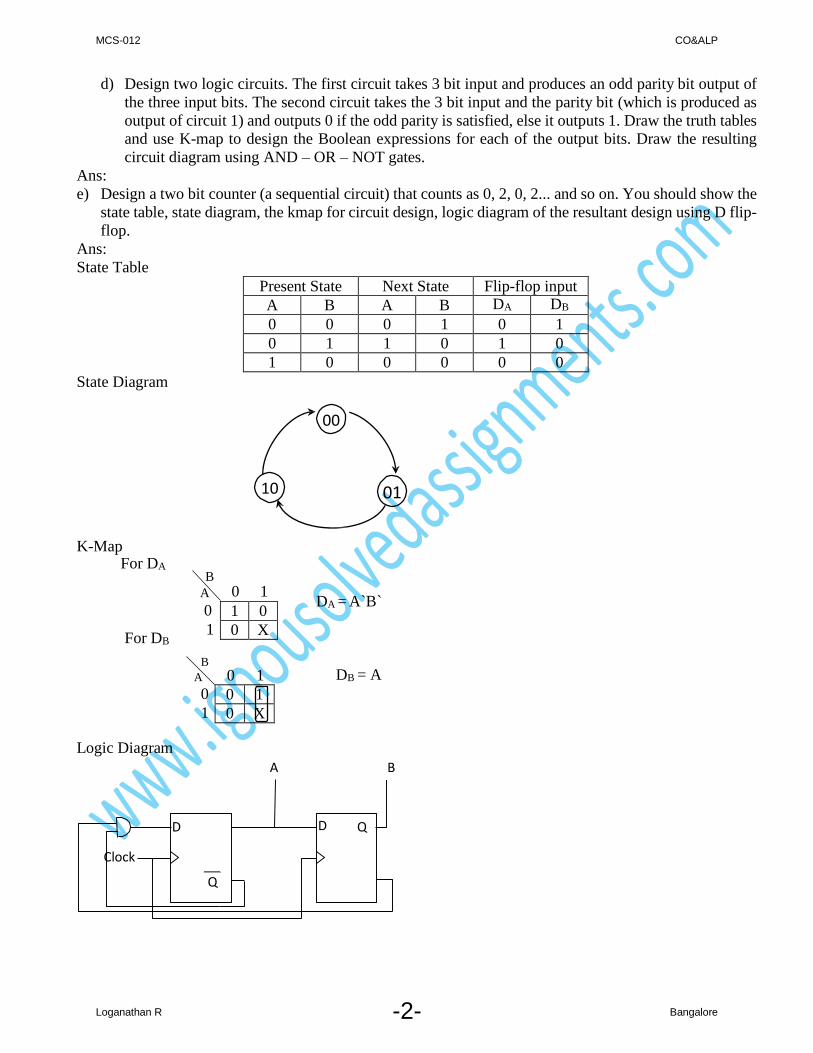
e) Design a two bit counter (a sequential circuit) that counts as 0, 2, 0, 2... and so on. You should show the
state table, state diagram, the kmap for circuit design, logic diagram of the resultant design using D flip-
flop.
Ans:
State Table
Present State Next State Flip-flop input
A B A B DA DB
0 0 0 1 0 1
0 1 1 0 1 0
1 0 0 0 0 0
State Diagram
00
10 01
K-Map For DA
For DB
B
A 0 1
0
1
B
A 0 1 0
1
DA = A`B`
DB = A
Logic Diagram
A B
D D Q
Clock
Q
MCS-012 CO&ALP
-3- Loganathan R Bangalore
f) Design a floating point representation of size 24 bits closer to IEEE 754 format. The number should
have a 7 bit biased exponent having a bias of 64. You may assume that the mantissa is in normalised
form with first bit being the sign bit of mantissa. Represent the number (34.125)10 using this format Ans:
Binary of 24.125 = 100010.001
Normalized Form = 1.00010001X25
Sign bit = 0
Exponent = 5
Biased Exponent = 63+5
= 68
= 1000100
Significand = 0001000100000000
23 22 16 15 0
0 1 0 0 0 1 0 0 1 0 0 0 1 0 0 0 1 0 0 0 0 0 0 0 0
S Exponent Significand
Question 2
a. A RAM has a capacity of 256K × 8. (i) How many data input and output lines does this RAM need? Explain your answer.
(ii) How many address lines will be needed for this RAM? Explain
Ans:
i) Data Input Lines = 8 ,
Data Output Lines = 8, Since each location stores only 8 bit
ii) Number of Address Lines Required = 18, Since 256 X 1024 Locations are addressed
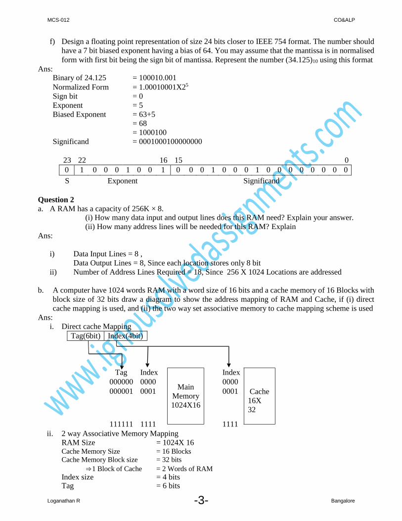
b. A computer have 1024 words RAM with a word size of 16 bits and a cache memory of 16 Blocks with
block size of 32 bits draw a diagram to show the address mapping of RAM and Cache, if (i) direct
cache mapping is used, and (ii) the two way set associative memory to cache mapping scheme is used
Ans:
i. Direct cache Mapping
Tag(6bit) Index(4bit)
Tag Index
000000 0000
000001 0001
Main
Memory
1024X16
Index
0000
0001
Cache
16X
32
111111 1111 1111
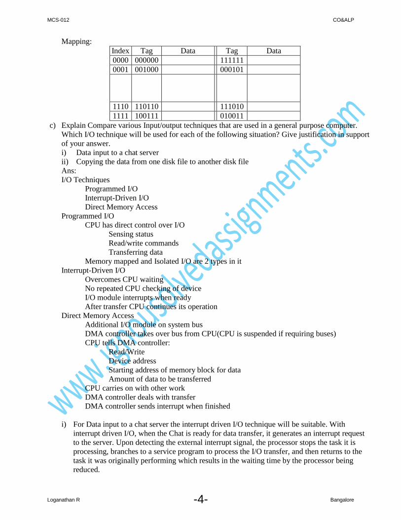
ii. 2 way Associative Memory Mapping
RAM Size = 1024X 16 Cache Memory Size = 16 Blocks
Cache Memory Block size = 32 bits
⇒1 Block of Cache = 2 Words of RAM
Index size = 4 bits Tag = 6 bits
MCS-012 CO&ALP
-4- Loganathan R Bangalore
Mapping:
Index Tag Data Tag Data
0000 000000 111111
0001 001000 000101
1110 110110 111010
1111 100111 010011
c) Explain Compare various Input/output techniques that are used in a general purpose computer.
Which I/O technique will be used for each of the following situation? Give justification in support
of your answer.
i) Data input to a chat server
ii) Copying the data from one disk file to another disk file
Ans:
I/O Techniques
Programmed I/O
Interrupt-Driven I/O
Direct Memory Access
Programmed I/O
CPU has direct control over I/O
Sensing status
Read/write commands
Transferring data
Memory mapped and Isolated I/O are 2 types in it
Interrupt-Driven I/O
Overcomes CPU waiting
No repeated CPU checking of device
I/O module interrupts when ready
After transfer CPU continues its operation
Direct Memory Access
Additional I/O module on system bus
DMA controller takes over bus from CPU(CPU is suspended if requiring buses)
CPU tells DMA controller:
Read/Write
Device address
Starting address of memory block for data
Amount of data to be transferred
CPU carries on with other work
DMA controller deals with transfer
DMA controller sends interrupt when finished
i) For Data input to a chat server the interrupt driven I/O technique will be suitable. With
interrupt driven I/O, when the Chat is ready for data transfer, it generates an interrupt request
to the server. Upon detecting the external interrupt signal, the processor stops the task it is
processing, branches to a service program to process the I/O transfer, and then returns to the
task it was originally performing which results in the waiting time by the processor being
reduced.

MCS-012 CO&ALP
-5- Loganathan R Bangalore
ii) For Copying the data from one disk file to another disk file the direct memory access (DMA)
technique is suitable since it requires large amount of data transfer from hard disk. In this
mode, the I/O interface and main memory exchange data directly, without the involvement of
processor. The DMA interface transfers the entire block of data, one word at a time, directly to
or from memory, without going through the processor. When the transfer is complete, the
DMA interface sends an interrupt signal to the processor.
d. Define various terms relating to access of a Magnetic disk. Find the average disk access time that
reads or writes to a 2048 byte sector. Assume that the disk rotates at 3000 rpm; each track of the disk
has 16 sectors and data transfer rate of the disk is 64 MB/second.
Ans:
Tracks and Sectors: The disk is divided into concentric rings called tracks. A track is one complete
rotation of the disk underneath the read/write head. Each track is subdivided into a number of sectors.
Each sector contains a specific number of bytes or characters.
Bad Blocks: The drive maintains an internal table which holds the sectors or tracks which cannot be
read or written to because of surface imperfections
Sector Interleave: This refers to the numbering of the sectors located in a track. A one to one interleave
has sectors numbered sequentially 0,1,2,3,4 etc.

MCS-012 CO&ALP
-6- Loganathan R Bangalore
Drive Speed: The amount of information that can be transferred in or out of the memory in a second is
termed as disk drive speed or data transfer rate
Bandwidth: The bandwidth can be measured in bytes per second it is the average data rate during a large
transfer, i.e., the number of bytes divided by the transfer time.
Access latency: A disk access simply moves the arm to the selected cylinder and waits for the rotational
latency, which may take less than 36ms
Rotation Speed: This refers to the speed of rotation of the disk. Most hard disks rotate at 7200 RPM
(Revolution per Minute)
Access Time: The access time is the time required between the requests made for a read or write
operation till the time the data are made available or written at the requested location
Seek Time: The seek time is the time for the disk arm to move the heads to the cylinder containing the
desired sector.
Latency Time: The latency time is the additional time waiting for the disk to rotate the desired sector to
the disk head.
Assume seek time = 12 ms
Average Rotational Latency = (0.5 * 60)/ 3000
= 1.ms
Transfer time = 2KB/64MB/s
=.02/1024s
= 0.04ms
Average Disk Access Time = Seek time + Rotational Latency + Transfer time
= 12 ms + 1.ms + 0.04ms
= 13.04ms e. What is the purpose of SCSI? Compare and contrast SCSI with that of IDE? Which of the two is
better for a Server? Justify your answer.
Ans:
To attach a disk drive to a PC via a SCSI interface. The common drive choice for servers or high-end
workstations with drive capacities ranges from 100MB to 20GB and rotation speed 7200RPM. It is a
common I/O interface between the adapter and disk drives or any other peripheral, i.e., CDROMs
drives, tape drives, printers, etc.
It uses a generic device controller (called SCSI controller) on the computer system and allows any
device with an SCSI interface to be directly connected to the SCSI bus of the SCSI controller. The SCSI
interface of a device contains all circuitry that the device needs to operate with the computer
These drives have fast access time and high data rates but are expensive but IDE is NOT.
A single SCSI controller can communicate simultaneously with up to seven 16-bit SCSI devices or up
to 15 Wide or Ultra-Wide devices but IDE can have 2 f. Define each of the following term. Explain the main purpose / use / advantage.
i. Inode
ii. Reading from CD-ROM disk
iii. Raster Display
iv. Use of colour depths
v. Scan codes in keyboards
vi. Resolution of monitor

MCS-012 CO&ALP
-7- Loganathan R Bangalore
Ans:
i) Inode (table)
It contains information about the space used by each individual file, the unused disk space and the space
that is unusable due to defects in the disk For each file, there is an inode entry in the table. Each entry
is made up of 64 bytes and contains the relevant details for that file. These details are:
a) Owner of the file, b) Group to which the Owner belongs c) File type d) File access permissions
e) Date & time of last access f) Date & time of last modification g) Size of the file h) No. of links
i) Addresses of blocks where the file is physically present.
ii) Reading from CD-ROM disk
The CD-ROM with pre-recorded information is read by a CD-ROM reader which uses a laser beam for
reading. It is rotated by a motor at a speed of 360 RPM. A laser head moves in and out to the specified
position. As the disk rotates the head senses pits and land. This is converted to 1s and 0s by the electronic
interface and sent to the computer
iii) Raster Display
Image represented by a rectangular grid of pixels (picture elements) image stored in a frame buffer
electron gun(s) continually scanning in a regular pattern (line by line across entire screen). The computer
must synchronize its "painting" of the screen with the scanning of the display. The computer only
controls the intensity of the color at each point on the screen. Usually a dedicated section of memory,
called the frame buffer, is used to store these intensity variation
iv) Use of colour depths
Colour Depth ( or the number of Colour Planes) is the number of bits assigned to each pixel to code
colour information in it. These are also called Colour Planes because each bit of a pixel represents a
specific colour and the bit at the same position on every pixel represents the same colour. Hence, the
bits at the same position can be thought of as forming a plane of a particular colour shade and these
planes piled on top of each other give the final colour at each point. Thus, if each pixel is described by
3 bits, one each for red, green and blue colour, then, there are 3 Colour Planes (one each for red, green
and blue)
v) Scan codes in keyboards
A scan code is the code generated by a microprocessor in the keyboard when a key is pressed and is
unique to the key struck. When this code is received by the computer it issues an interrupt and looks up
the scan code table in the BIOS and finds out which keys have been pressed and in what combination.
Special memory locations called status bytes tell the status of the locking and toggle keys, e.g., Caps
lock etc. Each keypress generates two different scan codes ― one on key-push down called Make code,
another on its popping back called Break code.
vi) Resolution of monitor
If the resolution generated by the video card and the monitor resolution is properly matched, you get a
good quality display. However, the actual resolution achieved is a physical quality of the monitor. In
colour systems, the resolution is limited by Convergence and the Dot Pitch. In monochrome monitors,
the resolution is only limited by the highest frequency signals the monitor can handle
Question 3
a) Assume that a new machine has been developed. This machine has 64 general purpose registers of
64 bits each. The machine has 2 GB main memory with memory word size of 32 bits. The Instructions
of this machine are of one or two memory words. Each instruction should have at most two operand
addresses. The machine implements the internal stack on 32 of its registers. List four addressing
MCS-012 CO&ALP
-8- Loganathan R Bangalore
Ans:
modes that must be supported by such a machine. Give justification of the selection of each of the
addressing modes..
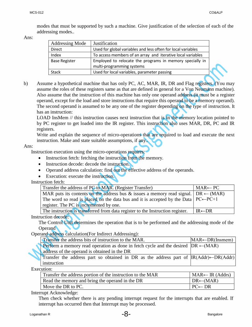
Addressing Mode Justification
Direct Used for global variables and less often for local variables
Index To access members of an array and iterative local variables
Base Register Employed to relocate the programs in memory specially in
multi-programming systems
Stack Used for local variables, parameter passing
b) Assume a hypothetical machine that has only PC, AC, MAR, IR, DR and Flag registers. (You may
assume the roles of these registers same as that are defined in general for a Von Neumann machine).
Also assume that the instruction of this machine has only one operand address (it must be a register
operand, except for the load and store instructions that require this operand to be a memory operand).
The second operand is assumed to be any one of the register depending on the type of instruction. It
has an instruction:
LOAD InsMem // this instruction causes next instruction that is in the memory location pointed to
by PC register to get loaded into the IR register. This instruction also uses MAR, DR, PC and IR
registers.
Write and explain the sequence of micro-operations that are required to load and execute the next
instruction. Make and state suitable assumptions, if any..
Ans:
Instruction execution using the micro-operations requires:
Instruction fetch: fetching the instruction from the memory.
Instruction decode: decode the instruction.
Operand address calculation: find out the effective address of the operands.
Execution: execute the instruction.
Instruction fetch:
Transfer the address of PC to MAR. (Register Transfer) MAR← PC
MAR puts its contents on the address bus & issues a memory read signal.
The word so read is placed on the data bus and it is accepted by the Data
register. The PC is incremented by one.
DR ← (MAR) PC←PC+1
The instruction is transferred from data register to the Instruction register. IR←DR
Instruction decode: The Control Unit determines the operation that is to be performed and the addressing mode of the
Operand
Operand address calculation(For Indirect Addressing):
Transfer the address bits of instruction to the MAR. MAR←DR(Insmem)
Perform a memory read operation as done in fetch cycle and the desired
address of the operand is obtained in the DR
DR ←(MAR)
Transfer the address part so obtained in DR as the address part of
instruction
IR(Addr)←DR(Addr)
Execution:
Transfer the address portion of the instruction to the MAR MAR← IR (Addrs)
Read the memory and bring the operand in the DR DR←(MAR)
Move the DR to PC. PC← DR
Interrupt Acknowledge: Then check whether there is any pending interrupt request for the interrupts that are enabled. If
interrupt has occurred then that Interrupt may be processed.
MCS-012 CO&ALP
-9- Loganathan R Bangalore
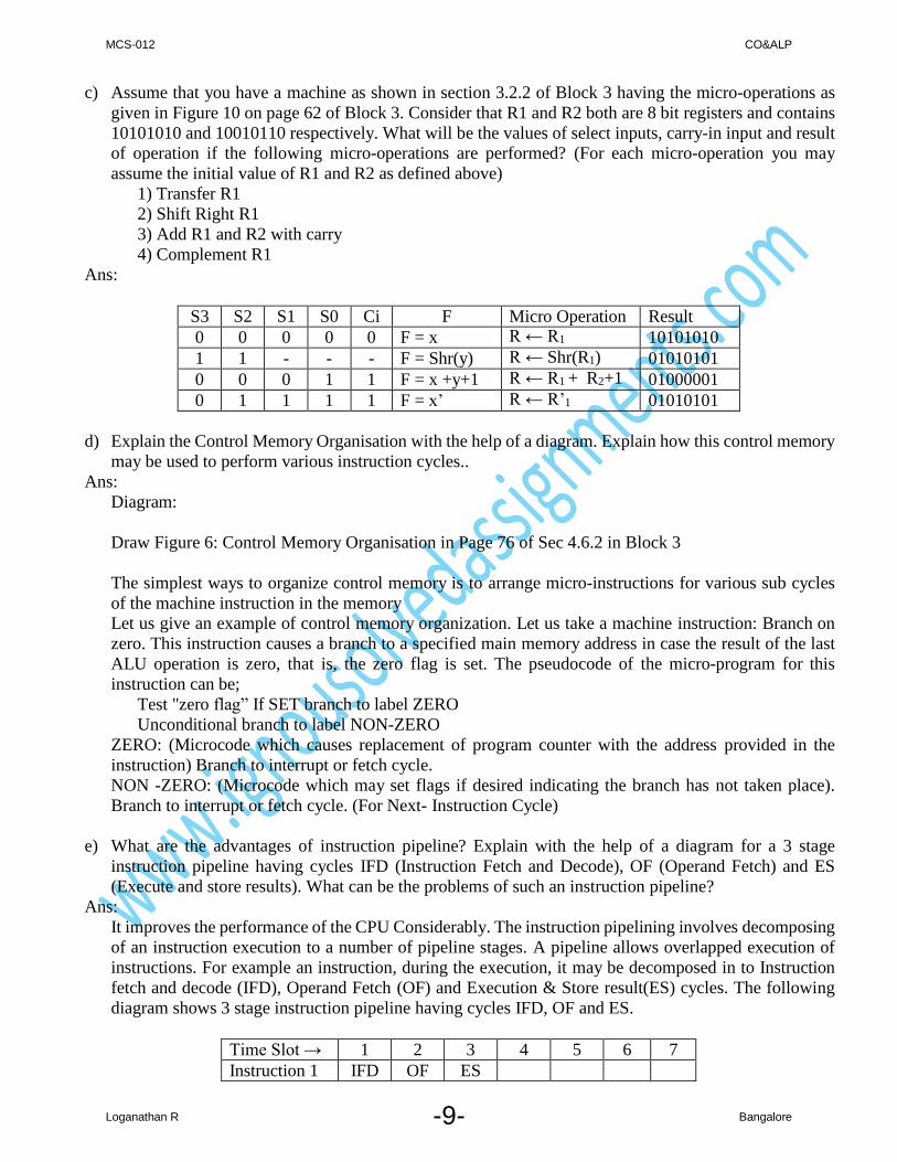
c) Assume that you have a machine as shown in section 3.2.2 of Block 3 having the micro-operations as
given in Figure 10 on page 62 of Block 3. Consider that R1 and R2 both are 8 bit registers and contains
10101010 and 10010110 respectively. What will be the values of select inputs, carry-in input and result
of operation if the following micro-operations are performed? (For each micro-operation you may
assume the initial value of R1 and R2 as defined above)
1) Transfer R1
2) Shift Right R1
3) Add R1 and R2 with carry
4) Complement R1
Ans:
S3 S2 S1 S0 Ci F Micro Operation Result
0 0 0 0 0 F = x R ← R1 10101010
1 1 - - - F = Shr(y) R ← Shr(R1) 01010101
0 0 0 1 1 F = x +y+1 R ← R1 + R2+1 01000001
0 1 1 1 1 F = x’ R ← R’1 01010101
d) Explain the Control Memory Organisation with the help of a diagram. Explain how this control memory
may be used to perform various instruction cycles..
Ans:
Diagram:
Draw Figure 6: Control Memory Organisation in Page 76 of Sec 4.6.2 in Block 3
The simplest ways to organize control memory is to arrange micro-instructions for various sub cycles
of the machine instruction in the memory
Let us give an example of control memory organization. Let us take a machine instruction: Branch on
zero. This instruction causes a branch to a specified main memory address in case the result of the last
ALU operation is zero, that is, the zero flag is set. The pseudocode of the micro-program for this
instruction can be;
Test "zero flag” If SET branch to label ZERO
Unconditional branch to label NON-ZERO
ZERO: (Microcode which causes replacement of program counter with the address provided in the
instruction) Branch to interrupt or fetch cycle.
NON -ZERO: (Microcode which may set flags if desired indicating the branch has not taken place).
Branch to interrupt or fetch cycle. (For Next- Instruction Cycle)
e) What are the advantages of instruction pipeline? Explain with the help of a diagram for a 3 stage
instruction pipeline having cycles IFD (Instruction Fetch and Decode), OF (Operand Fetch) and ES
(Execute and store results). What can be the problems of such an instruction pipeline?
Ans:
It improves the performance of the CPU Considerably. The instruction pipelining involves decomposing
of an instruction execution to a number of pipeline stages. A pipeline allows overlapped execution of
instructions. For example an instruction, during the execution, it may be decomposed in to Instruction
fetch and decode (IFD), Operand Fetch (OF) and Execution & Store result(ES) cycles. The following
diagram shows 3 stage instruction pipeline having cycles IFD, OF and ES.
Time Slot → 1 2 3 4 5 6 7
Instruction 1 IFD OF ES

-10-
Instruction 2 IFD OF ES
Instruction 3 IFD OF ES
Instruction 4 IFD OF ES
Instruction 5 IFD OF ES
The pipeline stages are like steps each to be completed in a time slot. The first instruction execution is
completed on completion of 3rd time slot, but afterwards, in each time slot the next instruction gets executed. So, in ideal conditions one instruction is executed in the pipeline in each time slot. After the
3rd time slot and afterwards the pipe is full.
Diagram for four stage instruction pipeline with following four cycle is:
IF (Instruction Fetch)
IAD(Instruction and Address Decode)
OF (Operand Fetch)
ES (Execute and store results)
Time Slot → 1 2 3 4 5 6 7 8
Instruction 1 IF IAD OF ES
Instruction 2 IF IAD OF ES
Instruction 3 IF IAD OF ES
Instruction 4 IF IAD OF ES
Instruction 5 IF IAD OF ES
f) Assume that a RISC machine has 64 registers out of which 16 registers are reserved for the Global
variables. Assuming that 8 of the registers are to be used for one function, explain how the remaining
registers will be used as overlapped register windows. How will these registers be used for parameter
passing for subroutine calls? Explain with the help of diagram.
Ans:
Register# Used For
0-31
(32 Registers)
Global Variable les
Required by
Function A
Function A
Function B
Function C
32-67 Unused
68-77
(10 Registers)
Used by parameters
of fC that may be passed to next call
Temporary
variables of
function C
78-83 (6 Registers)
Used for local
variable of fC
Local variables
of function C
84-97 (4+10
Registers)
Used by parameters
that were passed
from fB to fC
Temporary
variables of
function B
Parameters of
function C
98-103 (6 Registers)
Local variable of fB Local Variables
of function B
104-117 (4+10
Registers)
Parameters that were
passed from fA to fB
Temporary variables
of function A
Parameters of
function B
118-123 ( 6 Registers)
Local variable of fA Local Variables of
function A
124-127 (4 Registers)
Parameter passed to
fA
Parameters of
function A

-11-
Question 4 a) Write a program in 8086 Assembly Language (with proper comments) to find if the two given strings
of length 5 are reverse of each other. You may assume that both the strings are available in the memory.
Make suitable assumptions, if any.
Ans:
;Program to check if the two given strings of length 5 are reverse of each other.
.model small ;1 ds & 1 CS
.data ;Data Segment
str1 db 'madam'
str2 db 'madam'
slen dw slen-sstr
smsg db 'Both are Reverse of each $'
fmsg db 'Both are NOT Reverse of each $'
.code
start:
mov ax, @data
mov ds, ax ;initialize DS with Data Segment Base
mov es, ax ;initialize ES with Data Segment Base
lea si, str1 ;Offset of main string to SI
lea di, str2 ;Offset of sub string to DI
mov cx, slen ;String Length of strings to CX
repe cmpsb ;compare string1 with main string2
je ldmsg ;Mach found
lea dx, fmsg ;No match so store offset of Fail msg
jmp disp
ldmsg:
lea dx, smsg ;store offset of Success msg
disp:
mov ah, 9
int 21h ;Display message
mov ah, 4ch ;exit to operating system.
int 21h
end start ;stop the assembler.
Output:
Both are Reverse of each

-12-
b) Write a program in 8086 assembly language to convert a two digit unpacked BCD number into
equivalent ASCII digits and a packed BCD number. The packed BCD number is to be stored in BH
register. Your program should print the two ASCII digits. You may assume that the unpacked BCD
numbers are in the AL and BL registers
Ans:
;Unpacked BCD to ASCII & Packed BCD
.model small
.data
msg db 10,13,'Two ASCII Digits are '
asci1 db 30h,' and '
asci2 db 30h, '$'
.code segment
start:
mov ax, @data ;Initializing data Segment register
mov ds, ax
mov al, 2 ;1st Unpacked BCD numbeber
mov bl, 4 ;2nd Unpacked BCD numbeber
add asci1, al ;equalant ascii
add asci2, bl
mov bh, al ;1st Unpacked bcd to bh
mov cl, 4 ;to shift lower 4 bits to higher
shl bh, cl
or bh, bl ;Combine to get packed bcd in bh
lea dx, msg ;Display All
mov ah, 9
int 21h
mov ah, 4ch ; exit to operating system.
int 21h
end start ; stop the assembler.
Output:
Two ASCII Digits are 2 and 4

-13-
c) Write simple near procedure in 8086 assembly language that receives one parameter value in AL register
from the main module and returns sign bit of the input parameter. Make suitable assumptions, if any.
Ans:
; parameter is passed in register AL
.model small ;1 DS & 1 CS
.data ;Data Segment
msg db 'Sign bit returned is :$'
.code
start:
mov ax, @data
mov ds, ax ;initialize DS with Data Segment Base
mov al,80h ;Parameter to be passed to subroutine
call checks ;call subroutine
lea dx, msg
mov ah, 9
int 21h ;display message
mov dl, bl ;sign bit to ascii
add dl, 30h
mov ah, 2
int 21h ;display sign
mov ah, 4ch ;exit to operating system.
int 21h
proc checks
rcl al, 1 ;sign bit to carry
jc ngtv ; if carry negative
mov bl, 0 ;positive return 0
ret
ngtv:
mov bl, 1 ;negative return 1
ret
endp checkp ;end of procedure
end start ;stop the assembler.
Output:
Sign bit returned is :1
Related Documents