© 2007 Microchip Technology Inc. DS20090C-page 1 MCP23016 Features • 16-bit remote bidirectional I/O port - 16 I/O pins default to 16 inputs • Fast I 2 C™ bus clock frequency (0 - 400 kbits/s) • Three hardware address pins allow use of up to eight devices • High-current drive capability per I/O: ±25 mA • Open-drain interrupt output on input change • Interrupt port capture register • Internal Power-On Reset (POR) • Polarity inversion register to configure the polarity of the input port data • Compatible with most microcontrollers • Available temperature range: - Industrial (I): -40°C to +85°C CMOS Technology • Operating Supply Voltage: 2.0V to 5.5V • Low standby current Packages • 28-pin PDIP, 300 mil; 28-pin SOIC, 300 mil • 28-pin SSOP, 209 mil; 28-pin QFN, 6x6 mm Package Types Block Diagram Vss GP1.0 GP1.1 GP1.2 GP1.3 INT GP1.4 VSS CLK TP GP1.5 GP1.6 GP1.7 SCL GP0.7 GP0.6 GP0.5 GP0.4 GP0.3 GP0.2 GP0.1 GP0.0 VDD VSS A2 A1 A0 SDA • 1 2 3 4 5 6 7 8 9 10 11 12 13 14 28 27 26 25 24 23 22 21 20 19 18 17 16 15 PDIP, SOIC, SSOP QFN 2 3 4 5 6 1 7 GP1.2 GP1.3 INT GP1.4 VSS CLK TP 15 16 17 18 19 20 21 GP0.3 GP0.2 GP0.1 GP0.0 VDD VSS A2 GP1.5 GP1.6 GP1.7 SCL SDA A0 A1 23 24 25 26 27 28 22 GP1.1 GP1.0 Vss GP0.7 GP0.6 GP0.5 GP0.4 10 11 89 121314 MCP23016 MCP23016 16 Bits GP0.0 to GP0.7 GP1.0 to GP1.7 Write pulse Read pulse Low Pass Filter Interrupt Logic I 2 C™ Bus Control Address Decoder Power-on Reset I/O Port Deserializer Serializer/ Control Clock Gen I 2 C™ Bus Interface/ Protocol Handler INT A0 A1 A2 SCL SDA CLKIN VDD VSS Configuration Registers Control 8-Bit TP IARES 16-Bit I 2 C ™ I/O Expander

Welcome message from author
This document is posted to help you gain knowledge. Please leave a comment to let me know what you think about it! Share it to your friends and learn new things together.
Transcript
MCP2301616-Bit I2C™ I/O Expander
Features
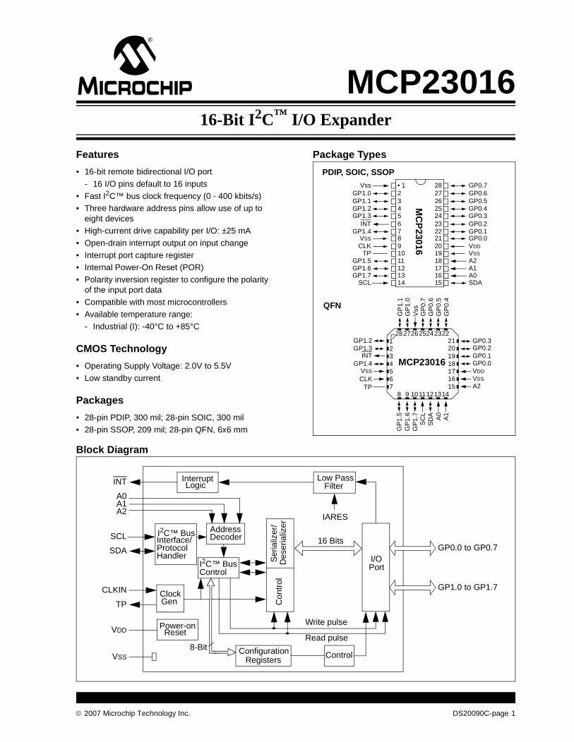
• 16-bit remote bidirectional I/O port
- 16 I/O pins default to 16 inputs• Fast I2C™ bus clock frequency (0 - 400 kbits/s)• Three hardware address pins allow use of up to
eight devices• High-current drive capability per I/O: ±25 mA
• Open-drain interrupt output on input change• Interrupt port capture register• Internal Power-On Reset (POR)
• Polarity inversion register to configure the polarity of the input port data
• Compatible with most microcontrollers• Available temperature range:
- Industrial (I): -40°C to +85°C
CMOS Technology
• Operating Supply Voltage: 2.0V to 5.5V
• Low standby current
Packages
• 28-pin PDIP, 300 mil; 28-pin SOIC, 300 mil• 28-pin SSOP, 209 mil; 28-pin QFN, 6x6 mm
Package Types
Block Diagram
VssGP1.0GP1.1GP1.2GP1.3
INTGP1.4
VSS
CLKTP
GP1.5GP1.6GP1.7
SCL
GP0.7GP0.6GP0.5GP0.4GP0.3GP0.2GP0.1GP0.0VDDVSS
A2A1A0SDA
• 1234567891011121314
2827262524232221201918171615
PDIP, SOIC, SSOP
QFN
23456
1
7
GP1.2GP1.3
INTGP1.4
VSS
CLKTP 15
161718192021 GP0.3
GP0.2GP0.1GP0.0VDD
VSS
A2
GP
1.5
GP
1.6
GP
1.7
SC
LS
DA A0
A1
232425262728 22
GP
1.1
GP
1.0
Vss
GP
0.7
GP
0.6
GP
0.5
GP
0.4
10118 9 121314
MCP23016
MC
P23016
16 BitsGP0.0 to GP0.7
GP1.0 to GP1.7
Write pulse
Read pulse
Low PassFilter
InterruptLogic
I2C™ BusControl
AddressDecoder
Power-onReset
I/OPort
Des
eria
lizer
Ser
ializ
er/
Con
trol
ClockGen
I2C™ BusInterface/ProtocolHandler
INT
A0A1A2
SCL
SDA
CLKIN
VDD
VSSConfiguration
RegistersControl
8-Bit
TP
IARES
© 2007 Microchip Technology Inc. DS20090C-page 1

MCP23016
NOTES:
DS20090C-page 2 © 2007 Microchip Technology Inc.

MCP23016
1.0 DEVICE OVERVIEW
The MCP23016 device provides 16-bit, generalpurpose, parallel I/O expansion for I2C busapplications.
This device includes high-current drive capability, lowsupply current and individual I/O configuration. I/Oexpanders provide a simple solution when additionalI/Os are needed for ACPI, power switches, sensors,push buttons, LEDs and so on.
The MCP23016 consists of multiple 8-bit configurationregisters for input, output and polarity selection. Thesystem master can enable the I/Os as either inputs oroutputs by writing the I/O configuration bits. The datafor each input or output is kept in the corresponding
input or output register. The polarity of the read registercan be inverted with the polarity inversion register (seeSection 1.7.3, “Input Polarity Registers”). Allregisters can be read by the system master.
The open-drain interrupt output is activated when anyinput state differs from its corresponding input portregister state. This is used to indicate to the systemmaster that an input state has changed. The interruptcapture register captures port value at this time. ThePower-on Reset sets the registers to their default val-ues and initializes the device state machine.
Three device inputs (A0 - A2) determine the I2Caddress and allow up to eight I/O expander devices toshare the same I2C bus.
1.1 Pin Descriptions
TABLE 1-1: PINOUT DESCRIPTION
Pin Name
PDIP,SOIC,SSOP
Pin No.
QFNPin No.
I/O/PType
BufferType
Description
CLK 9 6 I ST Clock source input
TP 10 7 O — Test Pin (This pin must be left floating)
GP1.0 2 27 I/O TTL D0 digital input/output for GP1
GP1.1 3 28 I/O TTL D1 digital input/output for GP1
GP1.2 4 1 I/O TTL D2 digital input/output for GP1
GP1.3 5 2 I/O TTL D3 digital input/output for GP1
GP1.4 7 4 I/O TTL D4 digital input/output for GP1
GP1.5 11 8 I/O ST D5 digital input/output for GP1
GP1.6 12 9 I/O ST D6 digital input/output for GP1
GP1.7 13 10 I/O ST D7 digital input/output for GP1
GP0.0 21 18 I/O TTL D0 digital input/output for GP0
GP0.1 22 19 I/O TTL D1 digital input/output for GP0
GP0.2 23 20 I/O TTL D2 digital input/output for GP0
GP0.3 24 21 I/O TTL D3 digital input/output for GP0
GP0.4 25 22 I/O TTL D4 digital input/output for GP0
GP0.5 26 23 I/O TTL D5 digital input/output for GP0
GP0.6 27 24 I/O TTL D6 digital input/output for GP0
GP0.7 28 25 I/O TTL D7 digital input/output for GP0
SCL 14 11 I ST Serial clock input
SDA 15 12 I/O ST Serial data I/O
INT 6 3 O OD Interrupt output
A0 16 13 I ST Address input 1
A1 17 14 I ST Address input 2
A2 18 15 I ST Address input 3
VSS 1, 8, 19 5, 16, 26 P — Ground reference for logic and I/O pins
VDD 20 17 P — Positive supply for logic and I/O pins
© 2007 Microchip Technology Inc. DS20090C-page 3
MCP23016
1.2 Power-on Reset (POR)
The on-chip POR circuit holds the chip in RESET untilVDD has reached a high enough level to deactivate thePOR circuit (i.e., release RESET). A maximum risetime for VDD is specified in the electrical specifications.
When the device starts normal operation (exits theRESET condition), device operating parameters(voltage, frequency, temperature) must be met toensure proper operation.
1.3 Power-up Timer (PWRT)
The Power-up Timer provides a 72 ms nominal time-out on power-up, keeping the device in RESET andallowing VDD to rise to an acceptable level.
The power-up time delay will vary from chip-to-chip dueto VDD, temperature and process variation. SeeTable 2-4 for details (TPWRT, parameter 3).
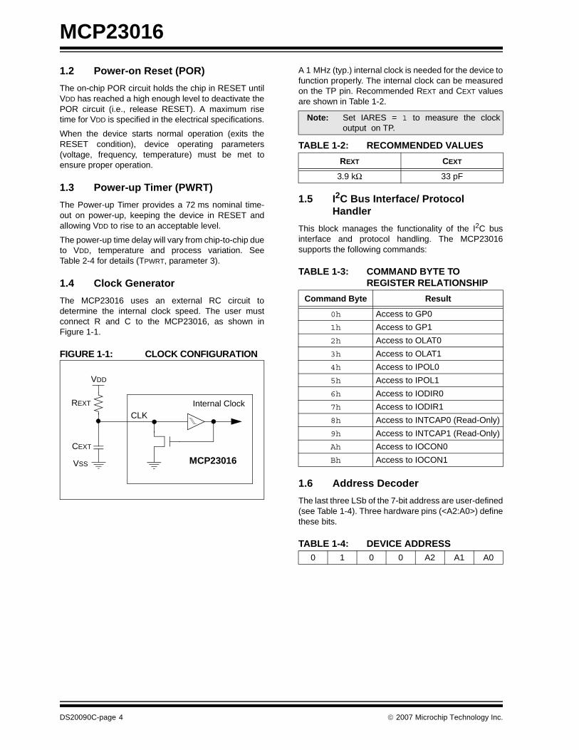
1.4 Clock Generator
The MCP23016 uses an external RC circuit todetermine the internal clock speed. The user mustconnect R and C to the MCP23016, as shown inFigure 1-1.
FIGURE 1-1: CLOCK CONFIGURATION
A 1 MHz (typ.) internal clock is needed for the device tofunction properly. The internal clock can be measuredon the TP pin. Recommended REXT and CEXT valuesare shown in Table 1-2.
1.5 I2C Bus Interface/ Protocol Handler
This block manages the functionality of the I2C businterface and protocol handling. The MCP23016supports the following commands:
TABLE 1-3: COMMAND BYTE TO REGISTER RELATIONSHIP
1.6 Address Decoder
The last three LSb of the 7-bit address are user-defined(see Table 1-4). Three hardware pins (<A2:A0>) definethese bits.
TABLE 1-4: DEVICE ADDRESS
Internal Clock
MCP23016
VDD
REXT
CEXT
VSS
CLK
Note: Set IARES = 1 to measure the clockoutput on TP.
TABLE 1-2: RECOMMENDED VALUES
REXT CEXT
3.9 kΩ 33 pF
Command Byte Result
0h Access to GP0
1h Access to GP1
2h Access to OLAT0
3h Access to OLAT1
4h Access to IPOL0
5h Access to IPOL1
6h Access to IODIR0
7h Access to IODIR1
8h Access to INTCAP0 (Read-Only)
9h Access to INTCAP1 (Read-Only)
Ah Access to IOCON0
Bh Access to IOCON1
0 1 0 0 A2 A1 A0
DS20090C-page 4 © 2007 Microchip Technology Inc.
MCP23016
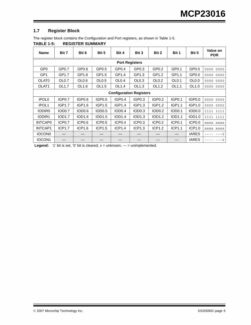
1.7 Register Block
The register block contains the Configuration and Port registers, as shown in Table 1-5.
TABLE 1-5: REGISTER SUMMARY
Name Bit 7 Bit 6 Bit 5 Bit 4 Bit 3 Bit 2 Bit 1 Bit 0Value on
POR
Port Registers
GP0 GP0.7 GP0.6 GP0.5 GP0.4 GP0.3 GP0.2 GP0.1 GP0.0 0000 0000
GP1 GP1.7 GP1.6 GP1.5 GP1.4 GP1.3 GP1.2 GP1.1 GP0.0 0000 0000
OLAT0 OL0.7 OL0.6 OL0.5 OL0.4 OL0.3 OL0.2 OL0.1 OL0.0 0000 0000
OLAT1 OL1.7 OL1.6 OL1.5 OL1.4 OL1.3 OL1.2 OL1.1 OL1.0 0000 0000
Configuration Registers
IPOL0 IGP0.7 IGP0.6 IGP0.5 IGP0.4 IGP0.3 IGP0.2 IGP0.1 IGP0.0 0000 0000
IPOL1 IGP1.7 IGP1.6 IGP1.5 IGP1.4 IGP1.3 IGP1.2 IGP1.1 IGP1.0 0000 0000
IODIR0 IOD0.7 IOD0.6 IOD0.5 IOD0.4 IOD0.3 IOD0.2 IOD0.1 IOD0.0 1111 1111
IODIR1 IOD1.7 IOD1.6 IOD1.5 IOD1.4 IOD1.3 IOD1.2 IOD1.1 IOD1.0 1111 1111
INTCAP0 ICP0.7 ICP0.6 ICP0.5 ICP0.4 ICP0.3 ICP0.2 ICP0.1 ICP0.0 xxxx xxxx
INTCAP1 ICP1.7 ICP1.6 ICP1.5 ICP1.4 ICP1.3 ICP1.2 ICP1.1 ICP1.0 xxxx xxxx
IOCON0 — — — — — — — IARES ---- ---0
IOCON1 — — — — — — — IARES ---- ---0
Legend: ‘1’ bit is set, ‘0’ bit is cleared, x = unknown, — = unimplemented.
© 2007 Microchip Technology Inc. DS20090C-page 5
MCP23016
1.7.1 DATA PORT REGISTERS
Two registers provide access to the two GPIO ports:
• GP0 (provides access to data port GP0)
• GP1 (provides access to data port GP1)
A read from this register provides status on pins ofthese ports. A write to these registers will modify theoutput latch registers (OLAT0, OLAT1) and data output.
REGISTER 1-1: GP0 - GENERAL PURPOSE I/O PORT REGISTER 0
REGISTER 1-2: GP1 - GENERAL PURPOSE I/O PORT REGISTER 1
R/W-0 R/W-0 R/W-0 R/W-0 R/W-0 R/W-0 R/W-0 R/W-0
GP0.7 GP0.6 GP0.5 GP0.4 GP0.3 GP0.2 GP0.1 GP0.0
bit 7 bit 0
bit 7-0 GP0.0:GP0.7: Reflects the logic level on the pins.1 = Logic ‘1’0 = Logic ‘0’
Legend:
R = Readable bit W = Writable bit U = Unimplemented bit, read as ‘0’
- n = Value at POR ‘1’ = Bit is set ‘0’ = Bit is cleared x = Bit is unknown
R/W-0 R/W-0 R/W-0 R/W-0 R/W-0 R/W-0 R/W-0 R/W-0
GP1.7 GP1.6 GP1.5 GP1.4 GP1.3 GP1.2 GP1.1 GP1.0
bit 7 bit 0
bit 7-0 GP1.0:GP1.7: Reflects the logic level on the pins.1 = Logic ‘1’0 = Logic ‘0’
Legend:
R = Readable bit W = Writable bit U = Unimplemented bit, read as ‘0’
- n = Value at POR ‘1’ = Bit is set ‘0’ = Bit is cleared x = Bit is unknown
DS20090C-page 6 © 2007 Microchip Technology Inc.
MCP23016
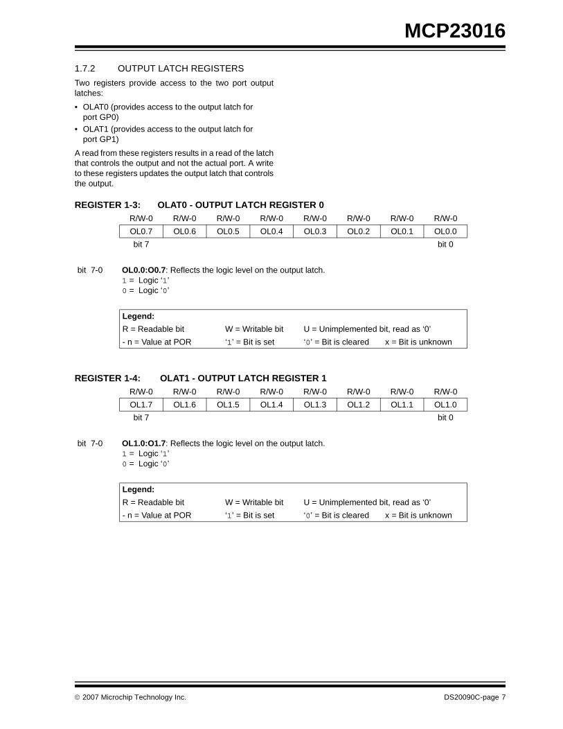
1.7.2 OUTPUT LATCH REGISTERS
Two registers provide access to the two port outputlatches:
• OLAT0 (provides access to the output latch for port GP0)
• OLAT1 (provides access to the output latch for port GP1)
A read from these registers results in a read of the latchthat controls the output and not the actual port. A writeto these registers updates the output latch that controlsthe output.
REGISTER 1-3: OLAT0 - OUTPUT LATCH REGISTER 0
REGISTER 1-4: OLAT1 - OUTPUT LATCH REGISTER 1
R/W-0 R/W-0 R/W-0 R/W-0 R/W-0 R/W-0 R/W-0 R/W-0
OL0.7 OL0.6 OL0.5 OL0.4 OL0.3 OL0.2 OL0.1 OL0.0
bit 7 bit 0
bit 7-0 OL0.0:O0.7: Reflects the logic level on the output latch.1 = Logic ‘1’0 = Logic ‘0’
Legend:
R = Readable bit W = Writable bit U = Unimplemented bit, read as ‘0’
- n = Value at POR ‘1’ = Bit is set ‘0’ = Bit is cleared x = Bit is unknown
R/W-0 R/W-0 R/W-0 R/W-0 R/W-0 R/W-0 R/W-0 R/W-0
OL1.7 OL1.6 OL1.5 OL1.4 OL1.3 OL1.2 OL1.1 OL1.0
bit 7 bit 0
bit 7-0 OL1.0:O1.7: Reflects the logic level on the output latch.1 = Logic ‘1’0 = Logic ‘0’
Legend:
R = Readable bit W = Writable bit U = Unimplemented bit, read as ‘0’
- n = Value at POR ‘1’ = Bit is set ‘0’ = Bit is cleared x = Bit is unknown
© 2007 Microchip Technology Inc. DS20090C-page 7
MCP23016
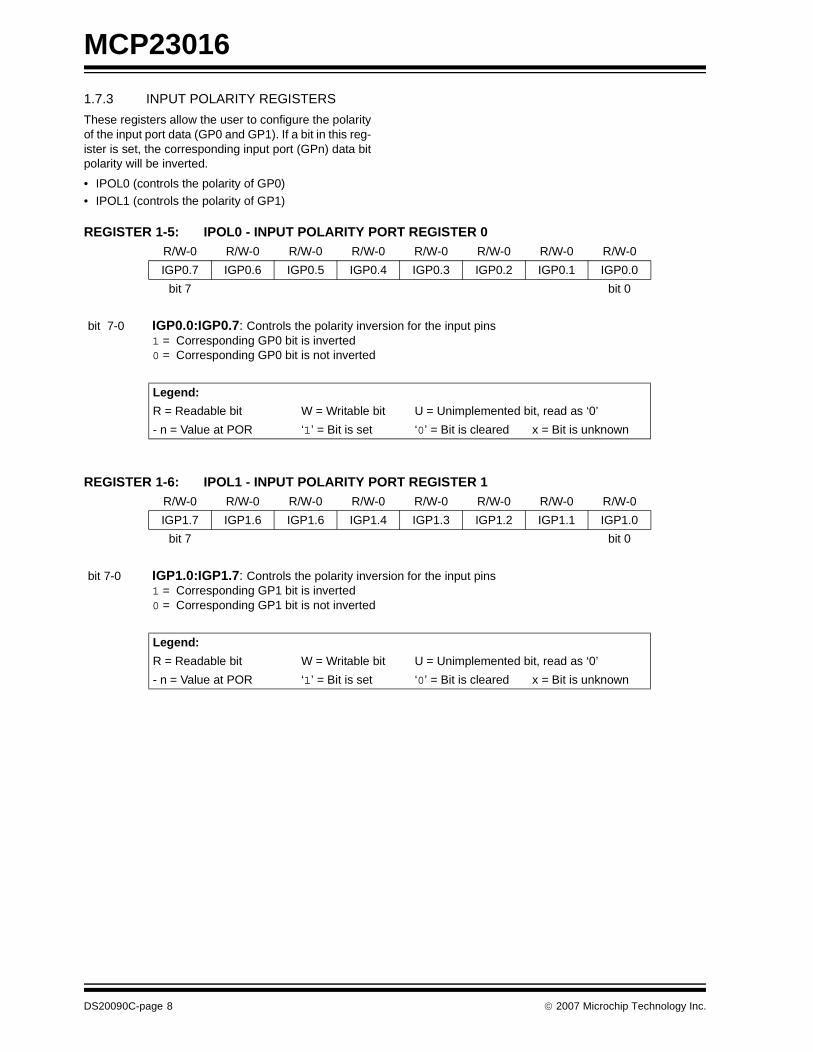
1.7.3 INPUT POLARITY REGISTERS
These registers allow the user to configure the polarityof the input port data (GP0 and GP1). If a bit in this reg-ister is set, the corresponding input port (GPn) data bitpolarity will be inverted.
• IPOL0 (controls the polarity of GP0)
• IPOL1 (controls the polarity of GP1)
REGISTER 1-5: IPOL0 - INPUT POLARITY PORT REGISTER 0
REGISTER 1-6: IPOL1 - INPUT POLARITY PORT REGISTER 1
R/W-0 R/W-0 R/W-0 R/W-0 R/W-0 R/W-0 R/W-0 R/W-0
IGP0.7 IGP0.6 IGP0.5 IGP0.4 IGP0.3 IGP0.2 IGP0.1 IGP0.0
bit 7 bit 0
bit 7-0 IGP0.0:IGP0.7: Controls the polarity inversion for the input pins1 = Corresponding GP0 bit is inverted0 = Corresponding GP0 bit is not inverted
Legend:
R = Readable bit W = Writable bit U = Unimplemented bit, read as ‘0’
- n = Value at POR ‘1’ = Bit is set ‘0’ = Bit is cleared x = Bit is unknown
R/W-0 R/W-0 R/W-0 R/W-0 R/W-0 R/W-0 R/W-0 R/W-0
IGP1.7 IGP1.6 IGP1.6 IGP1.4 IGP1.3 IGP1.2 IGP1.1 IGP1.0
bit 7 bit 0
bit 7-0 IGP1.0:IGP1.7: Controls the polarity inversion for the input pins1 = Corresponding GP1 bit is inverted0 = Corresponding GP1 bit is not inverted
Legend:
R = Readable bit W = Writable bit U = Unimplemented bit, read as ‘0’
- n = Value at POR ‘1’ = Bit is set ‘0’ = Bit is cleared x = Bit is unknown
DS20090C-page 8 © 2007 Microchip Technology Inc.

MCP23016
1.7.4 I/O DIRECTION REGISTERS
Two registers control the direction of data I/O:
• IODIR0 (controls GP0)
• IODIR1 (controls GP1)
When a bit in these registers is set, the correspondingpin becomes an input. Otherwise, it becomes anoutput. At Power-on Reset, the device ports areconfigured as inputs.
REGISTER 1-7: IODIR0 - I/O DIRECTION REGISTER 0
REGISTER 1-8: IODIR1 - I/O DIRECTION REGISTER 1
R/W-1 R/W-1 R/W-1 R/W-1 R/W-1 R/W-1 R/W-1 R/W-1
IOD0.7 IOD0.6 IOD0.5 IOD0.4 IOD0.3 IOD0.2 IOD0.1 IOD0.0
bit 7 bit 0
bit 7-0 IOD0.0:IO0.7: Controls the direction of data I/O1 = Input0 = Output
Legend:
R = Readable bit W = Writable bit U = Unimplemented bit, read as ‘0’
- n = Value at POR ‘1’ = Bit is set ‘0’ = Bit is cleared x = Bit is unknown
R/W-1 R/W-1 R/W-1 R/W-1 R/W-1 R/W-1 R/W-1 R/W-1
IOD1.7 IOD1.6 IOD1.5 IOD1.4 IOD1.3 IOD1.2 IOD1.1 IOD1.0
bit 7 bit 0
bit 7-0 IOD1.0:IO1.7: Controls the direction of data I/O1 = Input0 = Output
Legend:
R = Readable bit W = Writable bit U = Unimplemented bit, read as ‘0’
- n = Value at POR ‘1’ = Bit is set ‘0’ = Bit is cleared x = Bit is unknown
© 2007 Microchip Technology Inc. DS20090C-page 9
MCP23016
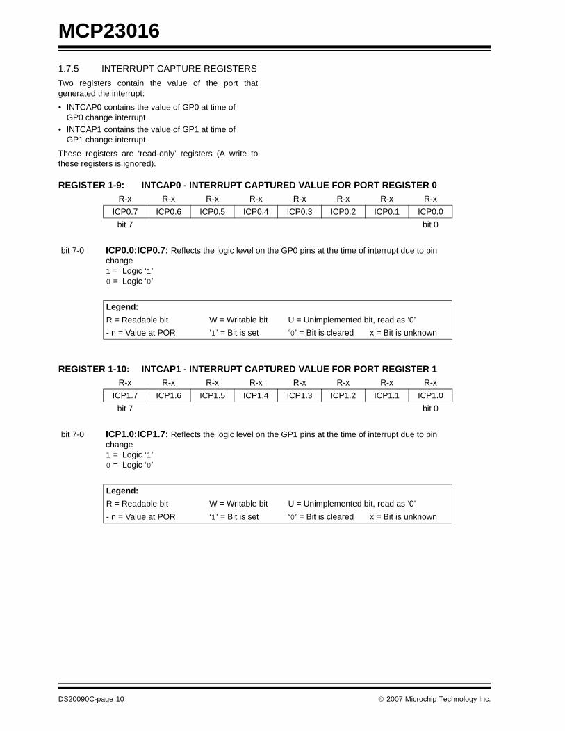
1.7.5 INTERRUPT CAPTURE REGISTERS
Two registers contain the value of the port thatgenerated the interrupt:
• INTCAP0 contains the value of GP0 at time of GP0 change interrupt
• INTCAP1 contains the value of GP1 at time of GP1 change interrupt
These registers are ‘read-only’ registers (A write tothese registers is ignored).
REGISTER 1-9: INTCAP0 - INTERRUPT CAPTURED VALUE FOR PORT REGISTER 0
REGISTER 1-10: INTCAP1 - INTERRUPT CAPTURED VALUE FOR PORT REGISTER 1
R-x R-x R-x R-x R-x R-x R-x R-x
ICP0.7 ICP0.6 ICP0.5 ICP0.4 ICP0.3 ICP0.2 ICP0.1 ICP0.0
bit 7 bit 0
bit 7-0 ICP0.0:ICP0.7: Reflects the logic level on the GP0 pins at the time of interrupt due to pin change1 = Logic ‘1’0 = Logic ‘0’
Legend:
R = Readable bit W = Writable bit U = Unimplemented bit, read as ‘0’
- n = Value at POR ‘1’ = Bit is set ‘0’ = Bit is cleared x = Bit is unknown
R-x R-x R-x R-x R-x R-x R-x R-x
ICP1.7 ICP1.6 ICP1.5 ICP1.4 ICP1.3 ICP1.2 ICP1.1 ICP1.0
bit 7 bit 0
bit 7-0 ICP1.0:ICP1.7: Reflects the logic level on the GP1 pins at the time of interrupt due to pin change1 = Logic ‘1’0 = Logic ‘0’
Legend:
R = Readable bit W = Writable bit U = Unimplemented bit, read as ‘0’
- n = Value at POR ‘1’ = Bit is set ‘0’ = Bit is cleared x = Bit is unknown
DS20090C-page 10 © 2007 Microchip Technology Inc.
MCP23016
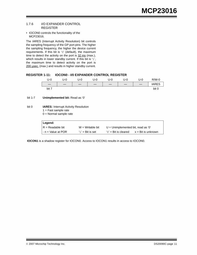
1.7.6 I/O EXPANDER CONTROL REGISTER
• IOCON0 controls the functionality of the MCP23016.
The IARES (Interrupt Activity Resolution) bit controlsthe sampling frequency of the GP port pins. The higherthe sampling frequency, the higher the device currentrequirements. If this bit is ‘0’ (default), the maximumtime to detect the activity on the port is 32 ms (max.),which results in lower standby current. If this bit is ‘1’,the maximum time to detect activity on the port is200 µsec. (max.) and results in higher standby current.
REGISTER 1-11: IOCON0 - I/0 EXPANDER CONTROL REGISTER U-0 U-0 U-0 U-0 U-0 U-0 U-0 R/W-0
— — — — — — — IARES
bit 7 bit 0
bit 1-7 Unimplemented bit: Read as ‘0’
bit 0 IARES: Interrupt Activity Resolution1 = Fast sample rate0 = Normal sample rate
Legend:
R = Readable bit W = Writable bit U = Unimplemented bit, read as ‘0’
- n = Value at POR ‘1’ = Bit is set ‘0’ = Bit is cleared x = Bit is unknown
IOCON1 is a shadow register for IOCON0. Access to IOCON1 results in access to IOCON0.
© 2007 Microchip Technology Inc. DS20090C-page 11
MCP23016
1.8 Serializer/Deserializer
The Serializer/Deserializer block converts andtransfers data between the I2C bus and GPIO.
1.9 Interrupt Logic
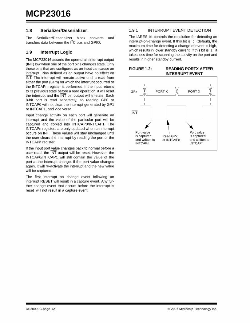
The MCP23016 asserts the open-drain interrupt output(INT) low when one of the port pins changes state. Onlythose pins that are configured as an input can cause aninterrupt. Pins defined as an output have no effect onINT. The interrupt will remain active until a read fromeither the port (GPn) on which the interrupt occurred orthe INTCAPn register is performed. If the input returnsto its previous state before a read operation, it will resetthe interrupt and the INT pin output will tri-state. Each8-bit port is read separately, so reading GP0 orINTCAP0 will not clear the interrupt generated by GP1or INTCAP1, and vice versa.
Input change activity on each port will generate aninterrupt and the value of the particular port will becaptured and copied into INTCAP0/INTCAP1. TheINTCAPn registers are only updated when an interruptoccurs on INT. These values will stay unchanged untilthe user clears the interrupt by reading the port or theINTCAPn register.
If the input port value changes back to normal before auser-read, the INT output will be reset. However, theINTCAP0/INTCAP1 will still contain the value of theport at the interrupt change. If the port value changesagain, it will re-activate the interrupt and the new valuewill be captured.
The first interrupt on change event following aninterrupt RESET will result in a capture event. Any fur-ther change event that occurs before the interrupt isreset will not result in a capture event.
1.9.1 INTERRUPT EVENT DETECTION
The IARES bit controls the resolution for detecting aninterrupt-on-change event. If this bit is ‘0’ (default), themaximum time for detecting a change of event is high,which results in lower standby current. If this bit is ‘1’, ittakes less time for scanning the activity on the port andresults in higher standby current.
FIGURE 1-2: READING PORTX AFTER INTERRUPT EVENT
Port value
PORT X PORT XGPx
INT
is capturedand written toINTCAPn
Port valueis capturedand written toINTCAPn
Read GPxor INTCAPn
DS20090C-page 12 © 2007 Microchip Technology Inc.
MCP23016
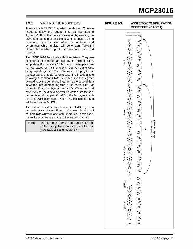
1.9.2 WRITING THE REGISTERS
To write to a MCP23016 register, the Master I2C deviceneeds to follow the requirements, as illustrated inFigure 1-3. First, the device is selected by sending theslave address and setting the R/W bit to logic ‘0’. Thecommand byte is sent after the address anddetermines which register will be written. Table 1-3shows the relationship of the command byte andregister.
The MCP23016 has twelve 8-bit registers. They areconfigured to operate as six 16-bit register pairs,supporting the device’s 16-bit port. These pairs areformed based on their functions (e.g., GP0 and GP1are grouped together). The I2C commands apply to oneregister pair to provide faster access. The first data bytefollowing a command byte is written into the registerpointed to by the command byte, while the second datais written into another register in the same pair. Forexample, if the first byte is sent to OLAT1 (commandbyte 03h), the next data byte will be written into the sec-ond register of that pair, OLAT0. If the first byte is writ-ten to OLAT0 (command byte 02h), the second bytewill be written to OLAT1.
There is no limitation on the number of data bytes inone write transmission. Figure 1-4 shows the case ofmultiple byte writes in one write operation. In this case,the multiple writes are made to the same data pair.
FIGURE 1-3: WRITE TO CONFIGURATION REGISTERS (CASE 1)
Note: The bus must remain free until after theninth clock pulse for a minimum of 12 µs(see Table 2-5 and Figure 2-4).
12
34
56
78
91
23
45
67
89
10
0A
2A
1A
0D
0
S
0
R/W
=0
AC
KD
6D
5D
4D
3D
2D
1D
7
12
34
56
78
91
23
45
67
89
D0
D6
D5
D4
D3
D2
D1
D7
AC
KD
0D
6D
5D
4D
3D
2D
1D
7A
CK
P
Add
ress
Com
man
d B
yte
Dat
a 1
Dat
a 2
AC
K
SC
L he
ld lo
w u
ntil
data
is p
roce
ssed
© 2007 Microchip Technology Inc. DS20090C-page 13

MCP23016
FIGURE 1-4: WRITE TO CONFIGURATION REGISTERS (CASE 2)
FIGURE 1-5: WRITE TO OUTPUT PORTS
1 2
3 4
5 6
7 8
9 1
2 3
4 5
6 7
8 9
1 0
0 A
2 A
1 A
0 D
0
S
0
R/W
=0
AC
K
D6
D5
D4
D3
D2
D1
D7
AC
K
1 2
3 4
5 6
7 8
9 1
2 3
4 5
6 7
8 9
D0
D6
D5
D4
D3
D2
D1
D7
AC
K
D0
D6
D5
D4
D3
D2
D1
D7
AC
K
Add
ress
C
omm
and
Byt
e D
ata
1 D
ata
2
1 2
3 4
5 6
7 8
9 1
2 3
4 5
6 7
8 9
D0
D6
D5
D4
D3
D2
D1
D7
AC
K
D0
D6
D5
D4
D3
D2
D1
D7
AC
K
P
Dat
a 1
Dat
a 2
SC
L he
ld lo
w u
ntil
data
is p
roce
ssed
SC
L he
ld lo
w u
ntil
data
is p
roce
ssed
12
34
56
78
91
23
45
67
89
10
0A
2A
1A
0D
0
S
0
R/W
=0
AC
KD
6D
5D
4D
3D
2D
1D
7A
CK
12
34
56
78
91
23
45
67
89
D0
D6
D5
D4
D3
D2
D1
D7
AC
KD
0D
6D
5D
4D
3D
2D
1D
7A
CK
P
Add
ress
Com
man
d B
yte
Dat
a 1
Dat
a 2
DA
TA V
ALI
D
t GP
V0
DA
TAVA
LID
t GP
V1
SD
A
SC
L Dat
a on
GP
0
Dat
a on
GP
1
SC
L he
ld lo
w u
ntil
data
is p
roce
ssed
DS20090C-page 14 © 2007 Microchip Technology Inc.
MCP23016
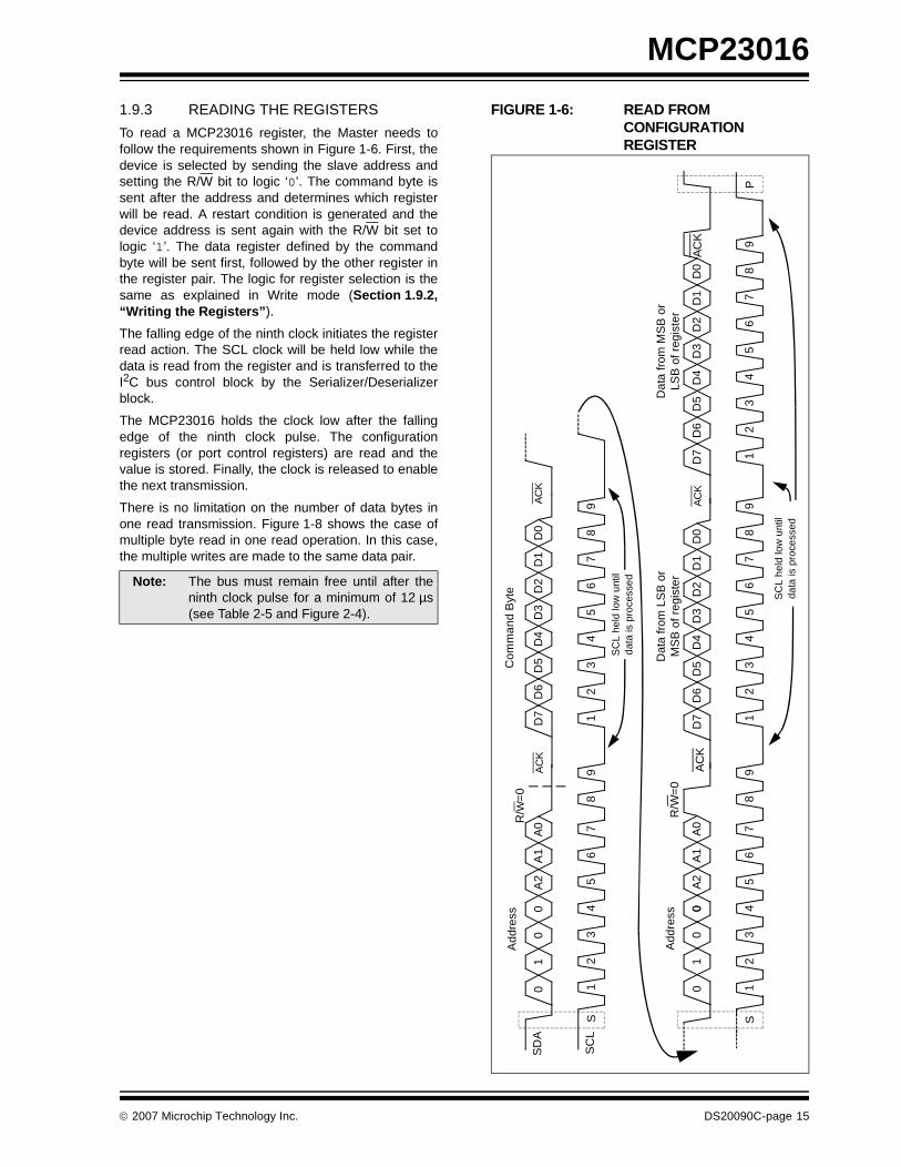
1.9.3 READING THE REGISTERS
To read a MCP23016 register, the Master needs tofollow the requirements shown in Figure 1-6. First, thedevice is selected by sending the slave address andsetting the R/W bit to logic ‘0’. The command byte issent after the address and determines which registerwill be read. A restart condition is generated and thedevice address is sent again with the R/W bit set tologic ‘1’. The data register defined by the commandbyte will be sent first, followed by the other register inthe register pair. The logic for register selection is thesame as explained in Write mode (Section 1.9.2,“Writing the Registers”).
The falling edge of the ninth clock initiates the registerread action. The SCL clock will be held low while thedata is read from the register and is transferred to theI2C bus control block by the Serializer/Deserializerblock.
The MCP23016 holds the clock low after the fallingedge of the ninth clock pulse. The configurationregisters (or port control registers) are read and thevalue is stored. Finally, the clock is released to enablethe next transmission.
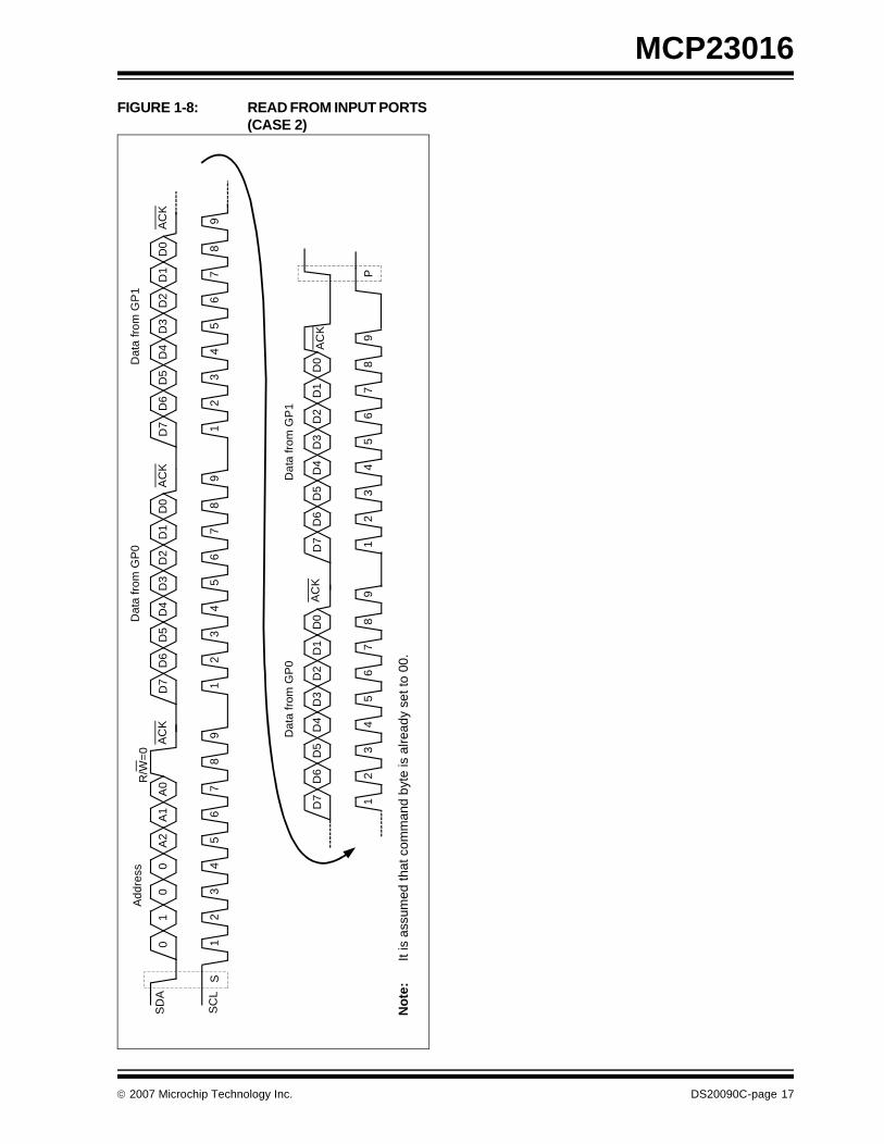
There is no limitation on the number of data bytes inone read transmission. Figure 1-8 shows the case ofmultiple byte read in one read operation. In this case,the multiple writes are made to the same data pair.
FIGURE 1-6: READ FROM CONFIGURATION REGISTER
Note: The bus must remain free until after theninth clock pulse for a minimum of 12 µs(see Table 2-5 and Figure 2-4).
12
34
56
78
91
23
45
67
89
10
0A
2A
1A
0D
0
S
0
R/W
=0
AC
KD
6D
5D
4D
3D
2D
1D
7A
CK
Add
ress
Com
man
d B
yte
12
34
56
78
91
23
45
67
89
10
0A
2A
1A
0D
0
S
0
R/W
=0
AC
KD
6D
5D
4D
3D
2D
1D
7A
CK
Add
ress
Dat
a fr
om L
SB
or
MS
B o
f reg
iste
r
12
34
56
78
9
D0
D6
D5
D4
D3
D2
D1
D7
AC
K
Dat
a fr
om M
SB
or
LSB
of r
egis
ter
P
SD
A
SC
L
SC
L he
ld lo
w u
ntil
data
is p
roce
ssed
SC
L he
ld lo
w u
ntil
data
is p
roce
ssed
0
© 2007 Microchip Technology Inc. DS20090C-page 15
MCP23016
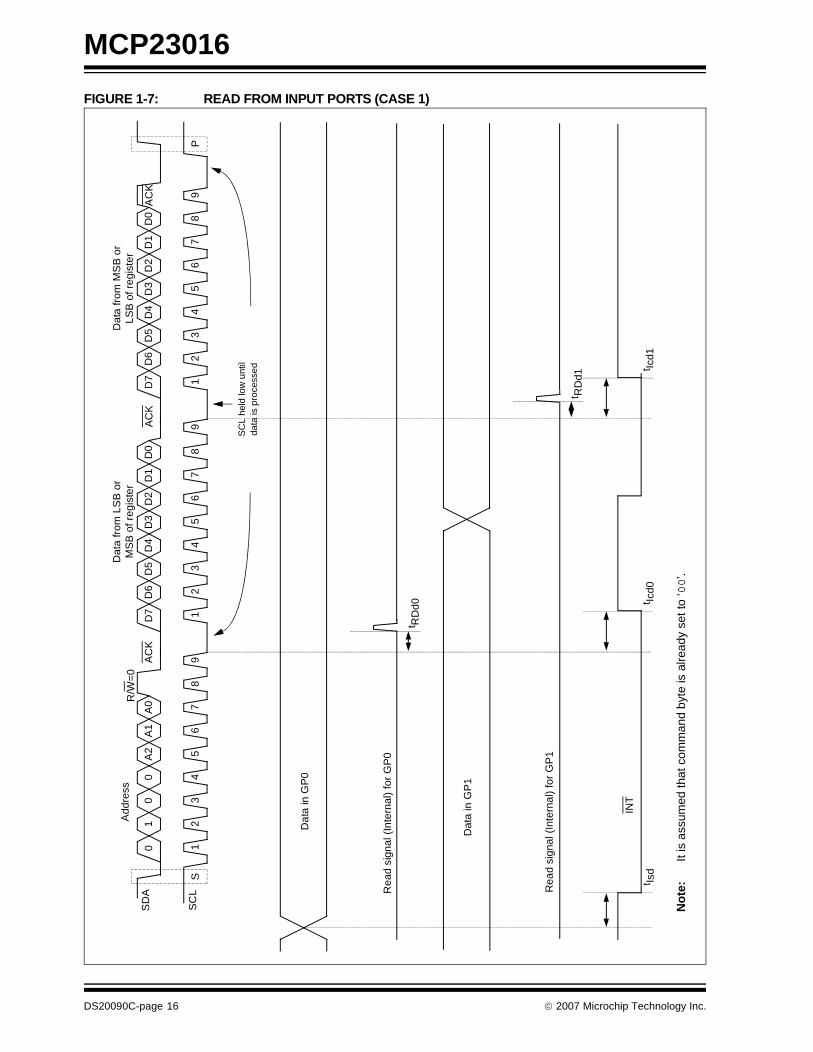
FIGURE 1-7: READ FROM INPUT PORTS (CASE 1)
No
te:
It is
ass
umed
that
com
man
d by
te is
alre
ady
set t
o ‘00
’.
12
34
56
78
91
23
45
67
89
10
0A
2A
1A
0D
0
S
0
R/W
=0
AC
KD
6D
5D
4D
3D
2D
1D
7A
CK
Add
ress
Dat
a fr
om L
SB
or
MS
B o
f reg
iste
r
12
34
56
78
9
D0
D6
D5
D4
D3
D2
D1
D7
AC
K
Dat
a fr
om M
SB
or
LSB
of r
egis
ter
P
Rea
d si
gnal
(In
tern
al)
for
GP
0
Rea
d si
gnal
(In
tern
al)
for
GP
1
t RD
d0
t RD
d1
t Icd0
t Isd
t Icd1
Dat
a in
GP
0
Dat
a in
GP
1
INT
SD
A
SC
L
SC
L he
ld lo
w u
ntil
data
is p
roce
ssed
DS20090C-page 16 © 2007 Microchip Technology Inc.
MCP23016
FIGURE 1-8: READ FROM INPUT PORTS (CASE 2)
12
34
56
78
91
23
45
67
89
10
0A
2A
1A
0D
0
S
0
R/W
=0
AC
KD
6D
5D
4D
3D
2D
1D
7A
CK
Add
ress
Dat
a fr
om G
P0
12
34
56
78
9
D0
D6
D5
D4
D3
D2
D1
D7
AC
K
Dat
a fr
om G
P1
12
34
56
78
9
D0
D6
D5
D4
D3
D2
D1
D7
AC
K
Dat
a fr
om G
P0
12
34
56
78
9
D0
D6
D5
D4
D3
D2
D1
D7
AC
K
Dat
a fr
om G
P1
P
No
te:
It is
ass
umed
that
com
man
d by
te is
alre
ady
set t
o 00
.
SD
A
SC
L
© 2007 Microchip Technology Inc. DS20090C-page 17

MCP23016
NOTES:
DS20090C-page 18 © 2007 Microchip Technology Inc.
MCP23016
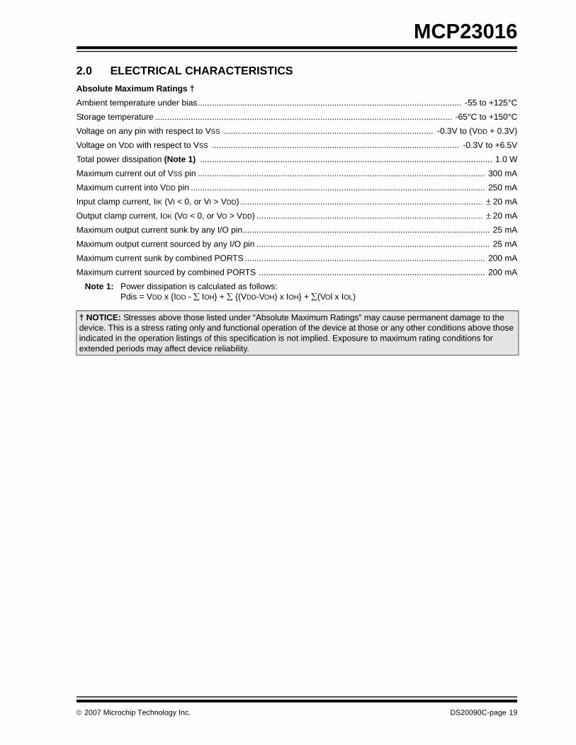
2.0 ELECTRICAL CHARACTERISTICS
Absolute Maximum Ratings †
Ambient temperature under bias................................................................................................................ -55 to +125°C
Storage temperature .............................................................................................................................. -65°C to +150°C
Voltage on any pin with respect to VSS ......................................................................................... -0.3V to (VDD + 0.3V)
Voltage on VDD with respect to VSS ......................................................................................................... -0.3V to +6.5V
Total power dissipation (Note 1) ............................................................................................................................ 1.0 W
Maximum current out of VSS pin .......................................................................................................................... 300 mA
Maximum current into VDD pin ............................................................................................................................. 250 mA
Input clamp current, IIK (VI < 0, or VI > VDD) ....................................................................................................... ± 20 mA
Output clamp current, IOK (VO < 0, or VO > VDD) ................................................................................................ ± 20 mA
Maximum output current sunk by any I/O pin......................................................................................................... 25 mA
Maximum output current sourced by any I/O pin ................................................................................................... 25 mA
Maximum current sunk by combined PORTS ...................................................................................................... 200 mA
Maximum current sourced by combined PORTS ................................................................................................ 200 mA
Note 1: Power dissipation is calculated as follows: Pdis = VDD x {IDD - ∑ IOH} + ∑ {(VDD-VOH) x IOH} + ∑(VOl x IOL)
† NOTICE: Stresses above those listed under “Absolute Maximum Ratings” may cause permanent damage to the device. This is a stress rating only and functional operation of the device at those or any other conditions above those indicated in the operation listings of this specification is not implied. Exposure to maximum rating conditions for extended periods may affect device reliability.
© 2007 Microchip Technology Inc. DS20090C-page 19

MCP23016
2.1 DC Characteristics
TABLE 2-1: DC CHARACTERISTICS
DC CHARACTERISTICSStandard Operating Conditions (unless otherwise stated)Operating temperature: -40°C ≤ TA ≤ +85°C for industrial
Param No.
Characteristic Sym Min Typ† Max Units Conditions
D001 Supply Voltage VDD 2.0 — 5.5 V
D002 Standby Current IDD — 0.4 mA IARES = 1
D003 Standby Current IPD — 25 µA IARES = 0
Input Low Voltage
I/O ports VIL
D004 TTL buffer Vss — 0.15 VDD V For entire VDD range
D004A Vss — 0.8V 4.5V ≤ VDD ≤ 5.5V
D005 Schmitt Trigger buffer Vss — 0.2 VDD V
Input High Voltage
I/O ports VIH —
D006 TTL buffer 2.0 — VDD V 4.5V ≤ VDD ≤ 5.5V
D006A 0.25 VDD + 0.8V
— VDD V For entire VDD range
D007 Schmitt Trigger buffer 0.8 VDD — VDD V For entire VDD range
Input Leakage Current
D008 I/O ports IIL — — ±1.0 µA Vss ≤ VPIN ≤ VDD,Pin at hi-impedance
D009 CLK — — ±5.0 µA Vss ≤ VPIN ≤ VDD
Output Low Voltage
D010 I/O Ports VOL — — 0.6 V IOL = 8.5 mA, VDD = 4.5V
Output High Voltage
D010 I/O Ports VOH VDD-0.7 — — V IOH = 3.0 mA, VDD = 4.5V
D011 VDD start voltage to ensure internal POR signal
VPOR — Vss — V
D012 VDD rise rate to ensure internal POR signal
SVDD 0.05 - — V/ms Note 1
DC Trip Point VTPOR 1.5 1.7 1.9 V DC Slow Ramp
D012 VDD rise rate to ensure internal POR signal with PWRT enabled
SVDD 0.05 — — V/ms Note 1
DC Current Draw IPOR — 5.0 — µA At 5.0V (1 µ/Volt typical)
Note 1: These parameters are characterized but not tested.2: Data in "Typ" column is at 5V, 25°C unless otherwise stated. These parameters are for design guidance
only and are not tested.
3: Standby current is measured with all I/O in hi-impedance state and tied to VDD and VSS.4: For RC CLK, current through REXT is not included. The current through the resistor can be estimated by
the formula Ir = VDD/2 REXT (mA) with REXT in kohm.
5: Negative current is defined as coming out of the pin.
DS20090C-page 20 © 2007 Microchip Technology Inc.
MCP23016
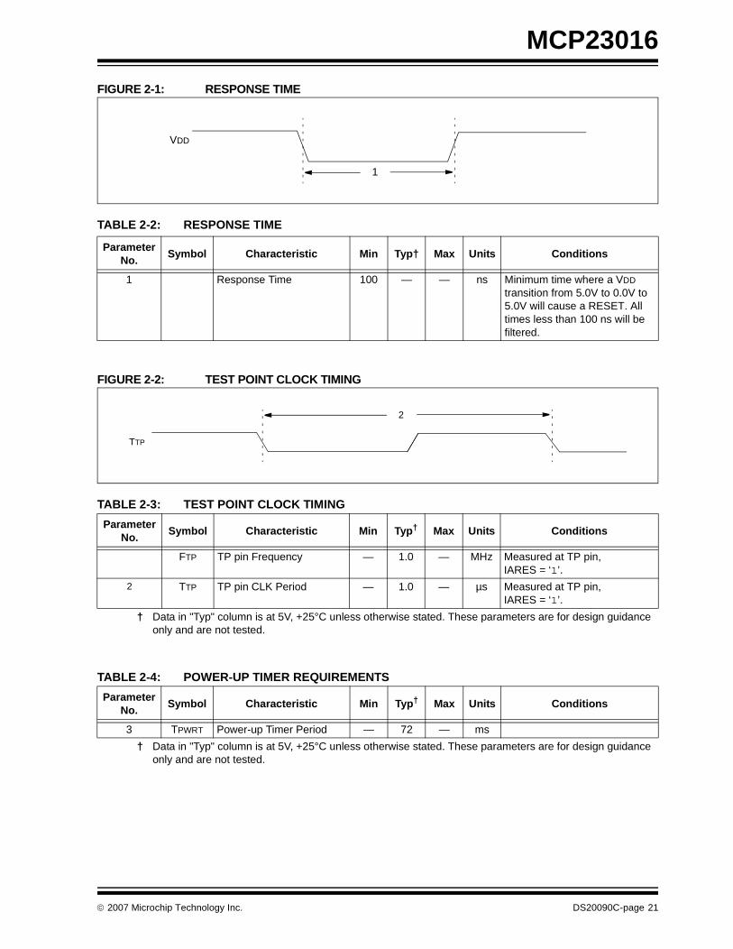
FIGURE 2-1: RESPONSE TIME
TABLE 2-2: RESPONSE TIME
FIGURE 2-2: TEST POINT CLOCK TIMING
TABLE 2-3: TEST POINT CLOCK TIMING
TABLE 2-4: POWER-UP TIMER REQUIREMENTS
VDD
1
Parameter No.
Symbol Characteristic Min Typ† Max Units Conditions
1 Response Time 100 — — ns Minimum time where a VDD transition from 5.0V to 0.0V to 5.0V will cause a RESET. All times less than 100 ns will be filtered.
Parameter No.
Symbol Characteristic Min Typ† Max Units Conditions
FTP TP pin Frequency — 1.0 — MHz Measured at TP pin,IARES = ‘1’.
2 TTP TP pin CLK Period — 1.0 — µs Measured at TP pin,IARES = ‘1’.
† Data in "Typ" column is at 5V, +25°C unless otherwise stated. These parameters are for design guidance only and are not tested.
TTP
2
Parameter No.
Symbol Characteristic Min Typ† Max Units Conditions
3 TPWRT Power-up Timer Period — 72 — ms
† Data in "Typ" column is at 5V, +25°C unless otherwise stated. These parameters are for design guidance only and are not tested.
© 2007 Microchip Technology Inc. DS20090C-page 21

MCP23016
FIGURE 2-3: I2C BUS START/STOP BITS TIMING
TABLE 2-5: I2C BUS START/STOP BITS REQUIREMENTS
ParamNo.
Symbol Characteristic MinTyp
Max Units Conditions
90 TSU:STA START condition 100 kHz mode 4700 — — ns Only relevant for Repeated START condition (Note 1)Setup time 400 kHz mode 600 — —
91 THD:STA START condition 100 kHz mode 4000 — — ns After this period, the first clock pulse is generated (Note 1)
Hold time 400 kHz mode 600 — —
92 TSU:STO STOP condition 100 kHz mode 4700 — — ns
Setup time 400 kHz mode 600 — —
93 THD:STO STOP condition 100 kHz mode 4000 — — ns
Hold time 400 kHz mode 600 — —
Note 1: These parameters are characterized but not tested.
91
92
93SCL
SDA
STARTCondition
STOPCondition
90
DS20090C-page 22 © 2007 Microchip Technology Inc.

MCP23016
FIGURE 2-4: I2C BUS DATA TIMING
90
91 92
100
101
103
106 107
109 109110
102
SCL
SDAIn
SDAOut
111
© 2007 Microchip Technology Inc. DS20090C-page 23
MCP23016
TABLE 2-5: I2C BUS DATA REQUIREMENTS
ParamNo.
Symbol Characteristic Min Max Units Conditions
100 THIGH Clock High Time 100 kHz mode 4.0 — µs (Note 1)
400 kHz mode 0.6 — µs
101 TLOW Clock Low Time 100 kHz mode 4.7 — µs (Note 1)
400 kHz mode 1.3 — µs
102 TR SDA and SCL Rise Time
100 kHz mode — 1000 ns (Note 1)
400 kHz mode 20 + 0.1 CB 300 ns CB is specified to be from 10 - 400 pF
103 TF SDA and SCL Fall Time
100 kHz mode — 300 ns (Note 1)
400 kHz mode 20 + 0.1 CB 300 ns CB is specified to be from 10 - 400 pF
90 TSU:STA START Condition Setup Time
100 kHz mode 4.7 — µs Only relevant for repeated START condition (Note 1)400 kHz mode 0.6 — µs
91 THD:STA START Condition Hold Time
100 kHz mode 4.0 — µs After this period, the first clock pulse is generated (Note 1)
400 kHz mode 0.6 — µs
106 THD:DAT Data Input Hold Time
100 kHz mode 0 — ns (Note 1)
400 kHz mode 0 0.9 µs
107 TSU:DAT Data Input Setup Time
100 kHz mode 250 — ns (Note 1) (Note 3)
400 kHz mode 100 — ns
92 TSU:STO STOP Condition Setup Time
100 kHz mode 4.7 — µs (Note 1)
400 kHz mode 0.6 — µs
109 TAA Output Valid from Clock
100 kHz mode — 3500 ns (Note 1) (Note 2)
400 kHz mode — — ns
110 TBUF Bus Free Time 100 kHz mode 4.7 — µs Time the bus must be free before a new transmis-sion can start (Note 1)
400 kHz mode 1.3 — µs
CB Bus Capacitive Loading — 400 pF
111 TWAIT Clock wait time after ninth pulse
100 kHz mode 12 µs — µs Time the bus must remain free after the ninth clock pulse before a new transmission can start.
400 kHz mode 12 µs — µs
Note 1: These parameters are characterized but not tested.
2: As a transmitter, the device must provide this internal minimum delay time to bridge the undefined region (min. 300 ns) of the falling edge of SCL to avoid unintended generation of START or STOP conditions.
3: A Fast mode (400 kHz) I2C bus device can be used in a Standard mode (100 kHz) I2C bus system, but the requirement TSU:DAT ≥ 250 ns must then be met. This will automatically be the case if the device does not stretch the LOW period of the SCL signal. If such a device does stretch the LOW period of the SCL signal, it must output the next data bit to the SDA line TR max.+TSU:DAT = 1000 + 250 = 1250 ns (according to the Standard mode I2C bus specification), before the SCL line is released.
DS20090C-page 24 © 2007 Microchip Technology Inc.
MCP23016
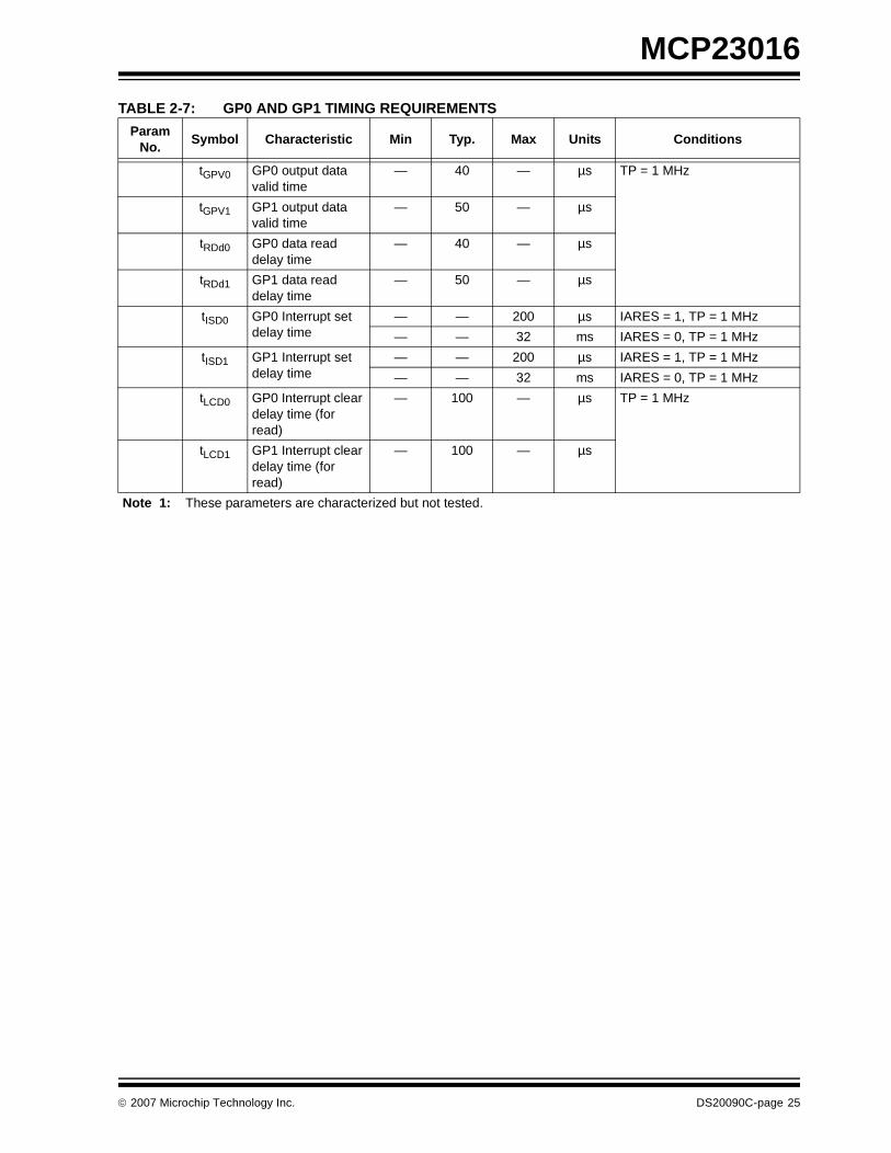
TABLE 2-7: GP0 AND GP1 TIMING REQUIREMENTS
ParamNo.
Symbol Characteristic Min Typ. Max Units Conditions
tGPV0 GP0 output data valid time
— 40 — µs TP = 1 MHz
tGPV1 GP1 output data valid time
— 50 — µs
tRDd0 GP0 data read delay time
— 40 — µs
tRDd1 GP1 data read delay time
— 50 — µs
tISD0 GP0 Interrupt set delay time
— — 200 µs IARES = 1, TP = 1 MHz
— — 32 ms IARES = 0, TP = 1 MHz
tISD1 GP1 Interrupt set delay time
— — 200 µs IARES = 1, TP = 1 MHz
— — 32 ms IARES = 0, TP = 1 MHz
tLCD0 GP0 Interrupt clear delay time (for read)
— 100 — µs TP = 1 MHz
tLCD1 GP1 Interrupt clear delay time (for read)
— 100 — µs
Note 1: These parameters are characterized but not tested.
© 2007 Microchip Technology Inc. DS20090C-page 25

MCP23016
FIGURE 2-5: GP0 AND GP1 PORT TIMINGS
No
te:
It is
ass
umed
that
com
man
d by
te is
alre
ady
set t
o ‘0
0’.
12
34
56
78
91
23
45
67
89
10
0A
2A
1A
0D
0
S
0
R/W
=0 A
CK
D6
D5
D4
D3
D2
D1
D7
AC
K
Add
ress
Dat
a fr
om L
SB
or
MS
B o
f reg
iste
r
12
34
56
78
9
D0
D6
D5
D4
D3
D2
D1
D7
AC
K
Dat
a fr
om M
SB
or
LSB
of r
egis
ter
P
Rea
d si
gnal
(Int
erna
l) fo
r G
P0
Rea
d si
gnal
(Int
erna
l) fo
r G
P1
t RD
d0
t RD
d1
t Icd0
t Isd
t Icd1
Dat
a in
GP
0
Dat
a in
GP
1
INT
SD
A
SC
L
SC
L he
ld lo
w u
ntil
data
is p
roce
ssed
DS20090C-page 26 © 2007 Microchip Technology Inc.
MCP23016
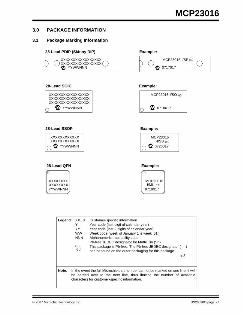
3.0 PACKAGE INFORMATION
3.1 Package Marking Information
Legend: XX...X Customer-specific informationY Year code (last digit of calendar year)YY Year code (last 2 digits of calendar year)WW Week code (week of January 1 is week ‘01’)NNN Alphanumeric traceability code Pb-free JEDEC designator for Matte Tin (Sn)* This package is Pb-free. The Pb-free JEDEC designator ( )
can be found on the outer packaging for this package.
Note: In the event the full Microchip part number cannot be marked on one line, it willbe carried over to the next line, thus limiting the number of availablecharacters for customer-specific information.
3e
3e
28-Lead SOIC
YYWWNNN
Example:
XXXXXXXXXXXXXXXXXYYWWNNN
28-Lead PDIP (Skinny DIP) Example:
XXXXXXXXXXXXXXXXXXXXXXXXXXXXXXXXXX
XXXXXXXXXXXXXXXXX
XXXXXXXXXXXXXXXXX
0717017
MCP23016-I/SP
0710017
MCP23016-I/SO
28-Lead SSOP
YYWWNNNXXXXXXXXXXXXXXXXXXXXXXXX
Example:
0720017
MCP23016
28-Lead QFN Example:
XXXXXXXXXXXXXXXXYYWWNNN
MCP23016-I/ML0710017
-I/SS
3e
3e
3e
3e
© 2007 Microchip Technology Inc. DS20090C-page 27
MCP23016
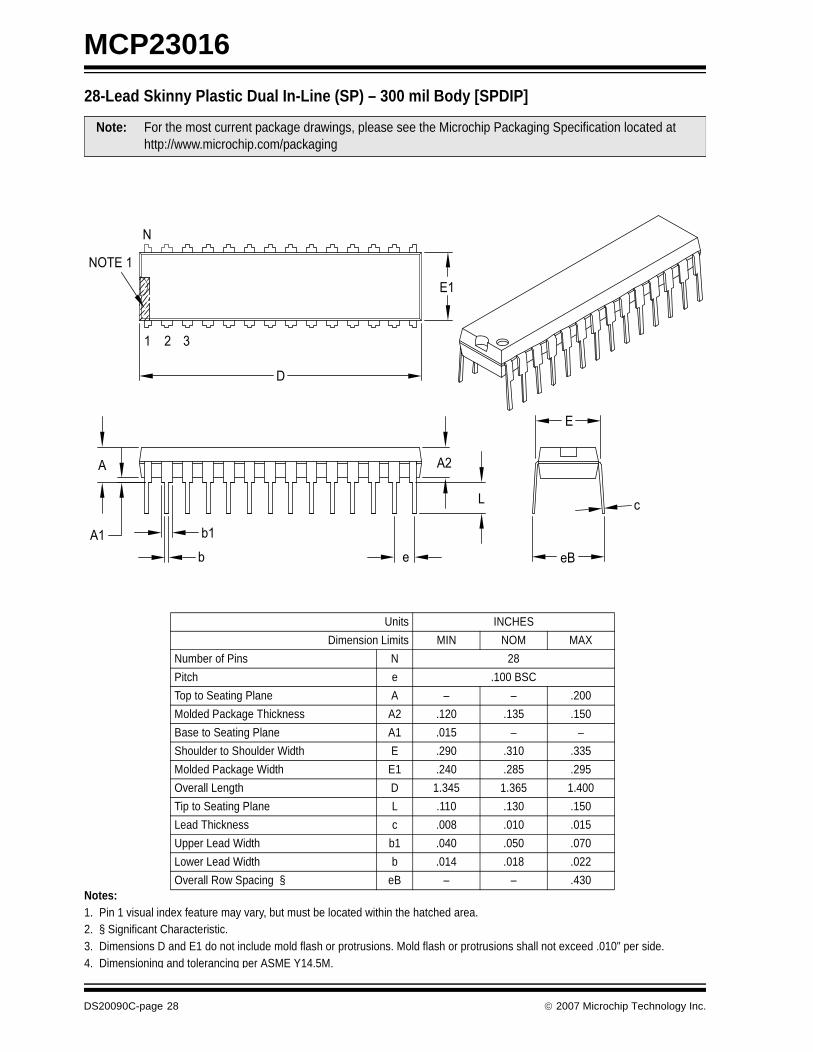
28-Lead Skinny Plastic Dual In-Line (SP) – 300 mil Body [SPDIP]Notes:1. Pin 1 visual index feature may vary, but must be located within the hatched area.2. § Significant Characteristic.3. Dimensions D and E1 do not include mold flash or protrusions. Mold flash or protrusions shall not exceed .010" per side.4. Dimensioning and tolerancing per ASME Y14.5M.
Note: For the most current package drawings, please see the Microchip Packaging Specification located at http://www.microchip.com/packaging
Units INCHES
Dimension Limits MIN NOM MAX
Number of Pins N 28
Pitch e .100 BSC
Top to Seating Plane A – – .200
Molded Package Thickness A2 .120 .135 .150
Base to Seating Plane A1 .015 – –
Shoulder to Shoulder Width E .290 .310 .335
Molded Package Width E1 .240 .285 .295
Overall Length D 1.345 1.365 1.400
Tip to Seating Plane L .110 .130 .150
Lead Thickness c .008 .010 .015
Upper Lead Width b1 .040 .050 .070
Lower Lead Width b .014 .018 .022
Overall Row Spacing § eB – – .430
NOTE 1
N
1 2
D
E1
eB
c
E
L
A2
eb
b1A1
A
3
DS20090C-page 28 © 2007 Microchip Technology Inc.
MCP23016
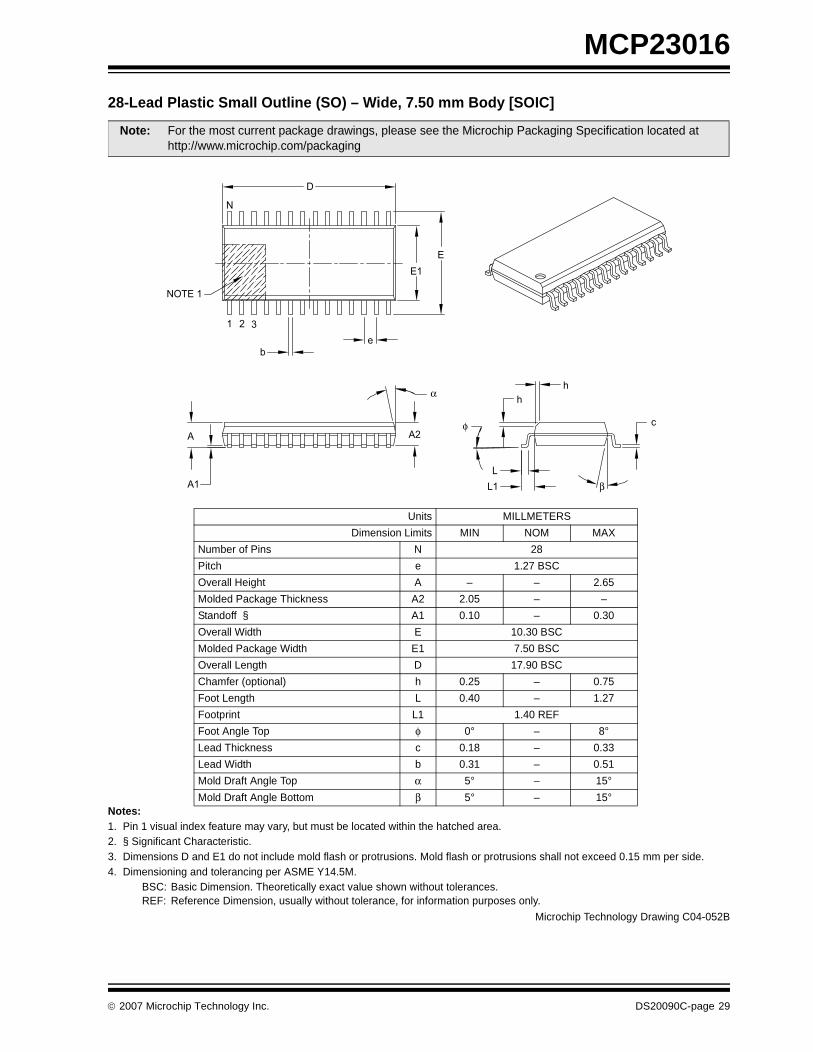
28-Lead Plastic Small Outline (SO) – Wide, 7.50 mm Body [SOIC]
Notes:1. Pin 1 visual index feature may vary, but must be located within the hatched area.2. § Significant Characteristic.3. Dimensions D and E1 do not include mold flash or protrusions. Mold flash or protrusions shall not exceed 0.15 mm per side.4. Dimensioning and tolerancing per ASME Y14.5M.
BSC: Basic Dimension. Theoretically exact value shown without tolerances.REF: Reference Dimension, usually without tolerance, for information purposes only.
Note: For the most current package drawings, please see the Microchip Packaging Specification located at http://www.microchip.com/packaging
Units MILLMETERS
Dimension Limits MIN NOM MAX
Number of Pins N 28
Pitch e 1.27 BSC
Overall Height A – – 2.65
Molded Package Thickness A2 2.05 – –
Standoff § A1 0.10 – 0.30
Overall Width E 10.30 BSC
Molded Package Width E1 7.50 BSC
Overall Length D 17.90 BSC
Chamfer (optional) h 0.25 – 0.75
Foot Length L 0.40 – 1.27
Footprint L1 1.40 REF
Foot Angle Top φ 0° – 8°
Lead Thickness c 0.18 – 0.33
Lead Width b 0.31 – 0.51
Mold Draft Angle Top α 5° – 15°
Mold Draft Angle Bottom β 5° – 15°
c
h
h
L
L1
A2
A1
A
NOTE 1
1 2 3
b
e
E
E1
D
φ
β
α
N
Microchip Technology Drawing C04-052B
© 2007 Microchip Technology Inc. DS20090C-page 29
MCP23016
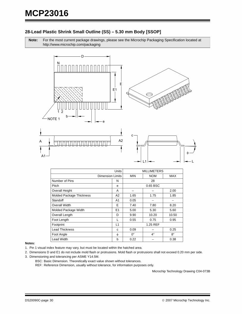
28-Lead Plastic Shrink Small Outline (SS) – 5.30 mm Body [SSOP]
Notes:1. Pin 1 visual index feature may vary, but must be located within the hatched area.2. Dimensions D and E1 do not include mold flash or protrusions. Mold flash or protrusions shall not exceed 0.20 mm per side.3. Dimensioning and tolerancing per ASME Y14.5M.
BSC: Basic Dimension. Theoretically exact value shown without tolerances.REF: Reference Dimension, usually without tolerance, for information purposes only.
Note: For the most current package drawings, please see the Microchip Packaging Specification located at http://www.microchip.com/packaging
Units MILLIMETERS
Dimension Limits MIN NOM MAX
Number of Pins N 28
Pitch e 0.65 BSC
Overall Height A – – 2.00
Molded Package Thickness A2 1.65 1.75 1.85
Standoff A1 0.05 – –
Overall Width E 7.40 7.80 8.20
Molded Package Width E1 5.00 5.30 5.60
Overall Length D 9.90 10.20 10.50
Foot Length L 0.55 0.75 0.95
Footprint L1 1.25 REF
Lead Thickness c 0.09 – 0.25
Foot Angle φ 0° 4° 8°
Lead Width b 0.22 – 0.38
LL1
c
A2
A1
A
E
E1
D
N
1 2
NOTE 1b
e
φ
Microchip Technology Drawing C04-073B
DS20090C-page 30 © 2007 Microchip Technology Inc.
MCP23016
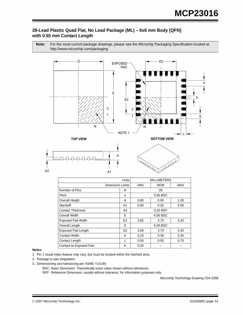
28-Lead Plastic Quad Flat, No Lead Package (ML) – 6x6 mm Body [QFN]with 0.55 mm Contact LengthNotes:1. Pin 1 visual index feature may vary, but must be located within the hatched area.2. Package is saw singulated.3. Dimensioning and tolerancing per ASME Y14.5M.
BSC: Basic Dimension. Theoretically exact value shown without tolerances.REF: Reference Dimension, usually without tolerance, for information purposes only.
Note: For the most current package drawings, please see the Microchip Packaging Specification located at http://www.microchip.com/packaging
Units MILLIMETERS
Dimension Limits MIN NOM MAX
Number of Pins N 28
Pitch e 0.65 BSC
Overall Height A 0.80 0.90 1.00
Standoff A1 0.00 0.02 0.05
Contact Thickness A3 0.20 REF
Overall Width E 6.00 BSC
Exposed Pad Width E2 3.65 3.70 4.20
Overall Length D 6.00 BSC
Exposed Pad Length D2 3.65 3.70 4.20
Contact Width b 0.23 0.30 0.35
Contact Length L 0.50 0.55 0.70
Contact-to-Exposed Pad K 0.20 – –
DEXPOSED
D2
e
b
K
E2
E
L
N
NOTE 1
1
22
1
N
A
A1A3
TOP VIEW BOTTOM VIEW
PAD
Microchip Technology Drawing C04-105B
© 2007 Microchip Technology Inc. DS20090C-page 31

MCP23016
NOTES:
DS20090C-page 32 © 2007 Microchip Technology Inc.
MCP23016
APPENDIX A: REVISION HISTORY
Revision A (December 2002)
Original data sheet for MCP23016 device.
Revision B (September 2003)
1. Addition of Output Low Voltage section toTable 2-1 in Electrical Characteristics.
2. Addition of Output High Voltage section toTable 2-1 in Electrical Characteristics.
Revision C (January 2007)
This revision includes updates to the packaging diagrams.
© 2007 Microchip Technology Inc. DS20090C-page 33

MCP23016
NOTES:
DS20090C-page 34 © 2007 Microchip Technology Inc.

MCP23016
PRODUCT IDENTIFICATION SYSTEMTo order or obtain information (e.g., on pricing or delivery) refer to the factory or the listed sales office.
PART NO. X /XX
PackageTemperatureRange
Device
Device: DSTEMP: 16-Bit I2C I/O Expander
Temperature Range:
I = -40°C to +85°C
Package: SP = Plastic DIP (300 mil Body), 28-leadSO = Plastic SOIC, Wide (300 mil Body), 28-leadSS = Plastic SOIC, (209 mil, 5.30mm), 28-leadML = Plastic Quad, Flat No Leads (QFN), 28-lead
Examples:
a) DSTEMP-I/P: Industrial Temperature,PDIP package.
a) DSTEMP-I/SO: Industrial Temperature, SOIC package.
a) DSTEMP-I/SS: Industrial Temperature,SOIC package.
a) DSTEMP-I/ML: Industrial Temperature,QFN package.
© 2007 Microchip Technology Inc. DS20090C-page 35

MCP23016
NOTES:
DS20090C-page 36 © 2007 Microchip Technology Inc.

Note the following details of the code protection feature on Microchip devices:
• Microchip products meet the specification contained in their particular Microchip Data Sheet.
• Microchip believes that its family of products is one of the most secure families of its kind on the market today, when used in the intended manner and under normal conditions.
• There are dishonest and possibly illegal methods used to breach the code protection feature. All of these methods, to our knowledge, require using the Microchip products in a manner outside the operating specifications contained in Microchip’s Data Sheets. Most likely, the person doing so is engaged in theft of intellectual property.
• Microchip is willing to work with the customer who is concerned about the integrity of their code.
• Neither Microchip nor any other semiconductor manufacturer can guarantee the security of their code. Code protection does not mean that we are guaranteeing the product as “unbreakable.”
Code protection is constantly evolving. We at Microchip are committed to continuously improving the code protection features of ourproducts. Attempts to break Microchip’s code protection feature may be a violation of the Digital Millennium Copyright Act. If such actsallow unauthorized access to your software or other copyrighted work, you may have a right to sue for relief under that Act.
Information contained in this publication regarding deviceapplications and the like is provided only for your convenienceand may be superseded by updates. It is your responsibility toensure that your application meets with your specifications.MICROCHIP MAKES NO REPRESENTATIONS ORWARRANTIES OF ANY KIND WHETHER EXPRESS ORIMPLIED, WRITTEN OR ORAL, STATUTORY OROTHERWISE, RELATED TO THE INFORMATION,INCLUDING BUT NOT LIMITED TO ITS CONDITION,QUALITY, PERFORMANCE, MERCHANTABILITY ORFITNESS FOR PURPOSE. Microchip disclaims all liabilityarising from this information and its use. Use of Microchipdevices in life support and/or safety applications is entirely atthe buyer’s risk, and the buyer agrees to defend, indemnify andhold harmless Microchip from any and all damages, claims,suits, or expenses resulting from such use. No licenses areconveyed, implicitly or otherwise, under any Microchipintellectual property rights.
© 2007 Microchip Technology Inc.
Trademarks
The Microchip name and logo, the Microchip logo, Accuron, dsPIC, KEELOQ, microID, MPLAB, PIC, PICmicro, PICSTART, PRO MATE, PowerSmart, rfPIC, and SmartShunt are registered trademarks of Microchip Technology Incorporated in the U.S.A. and other countries.
AmpLab, FilterLab, Migratable Memory, MXDEV, MXLAB, SEEVAL, SmartSensor and The Embedded Control Solutions Company are registered trademarks of Microchip Technology Incorporated in the U.S.A.
Analog-for-the-Digital Age, Application Maestro, CodeGuard, dsPICDEM, dsPICDEM.net, dsPICworks, ECAN, ECONOMONITOR, FanSense, FlexROM, fuzzyLAB, In-Circuit Serial Programming, ICSP, ICEPIC, Linear Active Thermistor, Mindi, MiWi, MPASM, MPLIB, MPLINK, PICkit, PICDEM, PICDEM.net, PICLAB, PICtail, PowerCal, PowerInfo, PowerMate, PowerTool, REAL ICE, rfLAB, rfPICDEM, Select Mode, Smart Serial, SmartTel, Total Endurance, UNI/O, WiperLock and ZENA are trademarks of Microchip Technology Incorporated in the U.S.A. and other countries.
SQTP is a service mark of Microchip Technology Incorporated in the U.S.A.
All other trademarks mentioned herein are property of their respective companies.
© 2007, Microchip Technology Incorporated, Printed in the U.S.A., All Rights Reserved.
Printed on recycled paper.
DS20090C-page 37
Microchip received ISO/TS-16949:2002 certification for its worldwide headquarters, design and wafer fabrication facilities in Chandler and Tempe, Arizona, Gresham, Oregon and Mountain View, California. The Company’s quality system processes and procedures are for its PIC®
MCUs and dsPIC DSCs, KEELOQ® code hopping devices, Serial EEPROMs, microperipherals, nonvolatile memory and analog products. In addition, Microchip’s quality system for the design and manufacture of development systems is ISO 9001:2000 certified.

DS20090C-page 38 © 2007 Microchip Technology Inc.
AMERICASCorporate Office2355 West Chandler Blvd.Chandler, AZ 85224-6199Tel: 480-792-7200 Fax: 480-792-7277Technical Support: http://support.microchip.comWeb Address: www.microchip.com
AtlantaDuluth, GA Tel: 678-957-9614 Fax: 678-957-1455
BostonWestborough, MA Tel: 774-760-0087 Fax: 774-760-0088
ChicagoItasca, IL Tel: 630-285-0071 Fax: 630-285-0075
DallasAddison, TX Tel: 972-818-7423 Fax: 972-818-2924
DetroitFarmington Hills, MI Tel: 248-538-2250Fax: 248-538-2260
KokomoKokomo, IN Tel: 765-864-8360Fax: 765-864-8387
Los AngelesMission Viejo, CA Tel: 949-462-9523 Fax: 949-462-9608
Santa ClaraSanta Clara, CA Tel: 408-961-6444Fax: 408-961-6445
TorontoMississauga, Ontario, CanadaTel: 905-673-0699 Fax: 905-673-6509
ASIA/PACIFICAsia Pacific OfficeSuites 3707-14, 37th FloorTower 6, The GatewayHabour City, KowloonHong KongTel: 852-2401-1200Fax: 852-2401-3431
Australia - SydneyTel: 61-2-9868-6733Fax: 61-2-9868-6755
China - BeijingTel: 86-10-8528-2100 Fax: 86-10-8528-2104
China - ChengduTel: 86-28-8665-5511Fax: 86-28-8665-7889
China - FuzhouTel: 86-591-8750-3506 Fax: 86-591-8750-3521
China - Hong Kong SARTel: 852-2401-1200 Fax: 852-2401-3431
China - QingdaoTel: 86-532-8502-7355Fax: 86-532-8502-7205
China - ShanghaiTel: 86-21-5407-5533 Fax: 86-21-5407-5066
China - ShenyangTel: 86-24-2334-2829Fax: 86-24-2334-2393
China - ShenzhenTel: 86-755-8203-2660 Fax: 86-755-8203-1760
China - ShundeTel: 86-757-2839-5507 Fax: 86-757-2839-5571
China - WuhanTel: 86-27-5980-5300Fax: 86-27-5980-5118
China - XianTel: 86-29-8833-7250Fax: 86-29-8833-7256
ASIA/PACIFICIndia - BangaloreTel: 91-80-4182-8400 Fax: 91-80-4182-8422
India - New DelhiTel: 91-11-4160-8631Fax: 91-11-4160-8632
India - PuneTel: 91-20-2566-1512Fax: 91-20-2566-1513
Japan - YokohamaTel: 81-45-471- 6166 Fax: 81-45-471-6122
Korea - GumiTel: 82-54-473-4301Fax: 82-54-473-4302
Korea - SeoulTel: 82-2-554-7200Fax: 82-2-558-5932 or 82-2-558-5934
Malaysia - PenangTel: 60-4-646-8870Fax: 60-4-646-5086
Philippines - ManilaTel: 63-2-634-9065Fax: 63-2-634-9069
SingaporeTel: 65-6334-8870Fax: 65-6334-8850
Taiwan - Hsin ChuTel: 886-3-572-9526Fax: 886-3-572-6459
Taiwan - KaohsiungTel: 886-7-536-4818Fax: 886-7-536-4803
Taiwan - TaipeiTel: 886-2-2500-6610 Fax: 886-2-2508-0102
Thailand - BangkokTel: 66-2-694-1351Fax: 66-2-694-1350
EUROPEAustria - WelsTel: 43-7242-2244-39Fax: 43-7242-2244-393Denmark - CopenhagenTel: 45-4450-2828 Fax: 45-4485-2829
France - ParisTel: 33-1-69-53-63-20 Fax: 33-1-69-30-90-79
Germany - MunichTel: 49-89-627-144-0 Fax: 49-89-627-144-44
Italy - Milan Tel: 39-0331-742611 Fax: 39-0331-466781
Netherlands - DrunenTel: 31-416-690399 Fax: 31-416-690340
Spain - MadridTel: 34-91-708-08-90Fax: 34-91-708-08-91
UK - WokinghamTel: 44-118-921-5869Fax: 44-118-921-5820
WORLDWIDE SALES AND SERVICE
12/08/06
Related Documents


![Table of contents · [2] TDE7318, Sunrise user guideline 2. I2C on Senseair Sunrise 2.1. I2C settings The sensor acts as a slave device on the I2C bus. Table 1, Senseair Sunrise I2C](https://static.cupdf.com/doc/110x72/5f027b307e708231d40479d1/table-of-contents-2-tde7318-sunrise-user-guideline-2-i2c-on-senseair-sunrise.jpg)
