MCEN 371 – Mechanical Engineering Lab Chapter 6: Chapter 6: LabVIEW LabVIEW Part 1: Introduction

MCEN 371 – Mechanical Engineering Lab Chapter 6: LabVIEW Part 1: Introduction.
Dec 26, 2015
Welcome message from author
This document is posted to help you gain knowledge. Please leave a comment to let me know what you think about it! Share it to your friends and learn new things together.
Transcript
MCEN 371 – Mechanical Engineering Lab
Chapter 6: Chapter 6: LabVIEWLabVIEW
Part 1: Introduction

MCEN 371 – Mechanical Engineering Lab
ObjectivesObjectives
• What is Data Acquisition and Why use it?
• Overview of LabVIEW– Develop an idea of what LabVIEW really is– Learn what graphical programming
language and dataflow mean– Get a feel for the LabVIEW environment
• Learning VI programming through example
MCEN 371 – Mechanical Engineering Lab
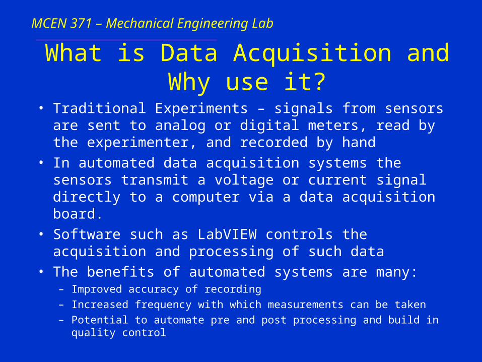
What is Data Acquisition and Why use it?
• Traditional Experiments – signals from sensors are sent to analog or digital meters, read by the experimenter, and recorded by hand
• In automated data acquisition systems the sensors transmit a voltage or current signal directly to a computer via a data acquisition board.
• Software such as LabVIEW controls the acquisition and processing of such data
• The benefits of automated systems are many:– Improved accuracy of recording
– Increased frequency with which measurements can be taken
– Potential to automate pre and post processing and build in quality control

MCEN 371 – Mechanical Engineering Lab
Overview of LabVIEW
• LabVIEW – Laboratory Virtual Instrument Engineering Workbench
• Graphical programming language that allows for instrument control, data acquisition, and pre/post processing of acquired data
MCEN 371 – Mechanical Engineering Lab
Graphical programming language& Data flow
• LabVIEW relies on graphical symbols rather than textual language to describe programming actions
• The principle of dataflow, in which functions execute only after receiving the necessary data, governs execution in a straightforward manner.
MCEN 371 – Mechanical Engineering Lab
How does LabVIEW work?
• LabVIEW programs are called:Virtual Instruments (VIs)
because their appearence and operation imitate actual instruments.
• However, they are analogous to main programs, functions and subroutines from popular language like C, Fortran, Pascal, …
MCEN 371 – Mechanical Engineering Lab
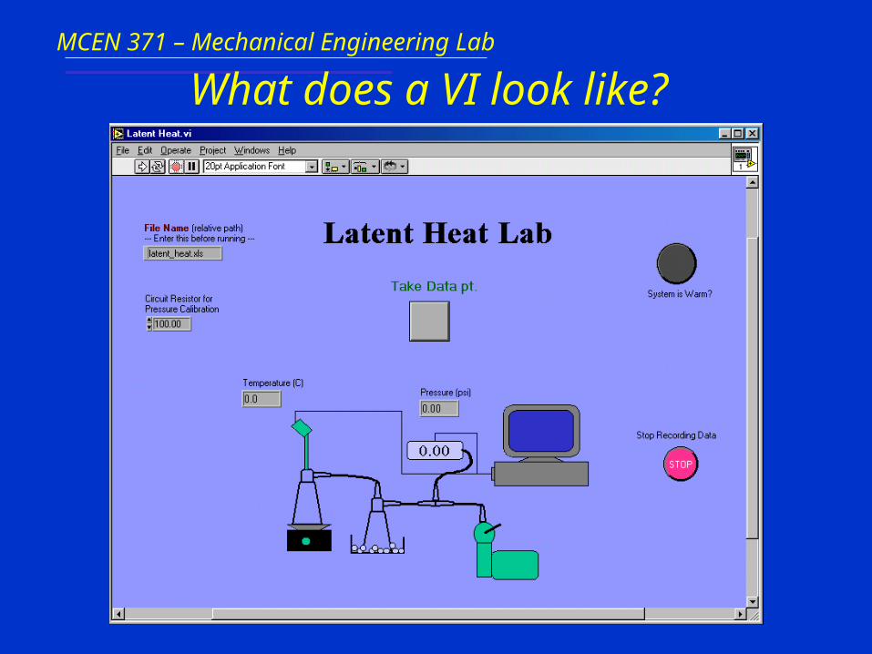
What does a VI look like?
MCEN 371 – Mechanical Engineering Lab
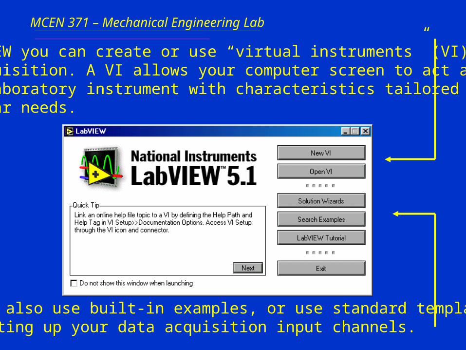
In LabVIEW you can create or use “virtual instruments” (VI) fordata acquisition. A VI allows your computer screen to act as an actual laboratory instrument with characteristics tailored to yourparticular needs.
You can also use built-in examples, or use standard templatesfor setting up your data acquisition input channels.

MCEN 371 – Mechanical Engineering Lab
A VI has three main parts:
1. The front panel: an interactive user interface of a VI, so named
because it can simulates the front panel of a physical instrument.
2. The block (or wiring) diagram:It is the VI’s source code, constructed in LabVIEW’s graphical programming language, G. It is the actualexecutable program.
Subroutine in the block diagram of VI.
3. Icon/connector
MCEN 371 – Mechanical Engineering Lab
Chapter 6: Chapter 6: LabVIEWLabVIEW
Part 2: The LabVIEW Environment
MCEN 371 – Mechanical Engineering Lab
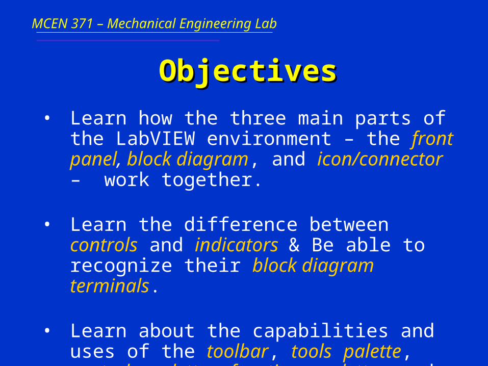
ObjectivesObjectives
• Learn how the three main parts of the LabVIEW environment – the front panel, block diagram, and icon/connector – work together.
• Learn the difference between controls and indicators & Be able to recognize their block diagram terminals.
• Learn about the capabilities and uses of the toolbar, tools palette, controls palette, functions palette, and subpalettes.

MCEN 371 – Mechanical Engineering Lab
Front Panels
Simply put, the front panel is
the window through which
the user interacts with the
program.• When you run a VI, you must
have the front panel open so that you can input data to the executing program.
• The front panel is where you see your program’s output.
MCEN 371 – Mechanical Engineering Lab
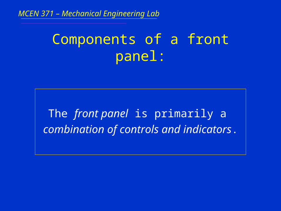
Components of a front panel:
The front panel is primarily a
combination of controls and indicators.
MCEN 371 – Mechanical Engineering Lab
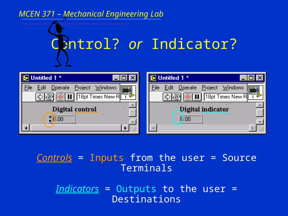
Control? or Indicator?
Controls = Inputs from the user = Source Terminals
Indicators = Outputs to the user = Destinations

MCEN 371 – Mechanical Engineering Lab
Manipulating Controls and Indicators
• Right click on an indicator to– Change to control
– Change format or precision
• Right click on a control to– Change to indicator
– Change mechanical action (whether to latch open or closed, and what to use as default…)

MCEN 371 – Mechanical Engineering Lab
Block Diagrams
The block diagram window
holds the graphical source
code of a LabVIEW VI – it is
the actual executable code• You construct the block
diagram by wiring together objects that perform specific functions.
• The various components of a block diagram are terminals, nodes and wires.
MCEN 371 – Mechanical Engineering Lab
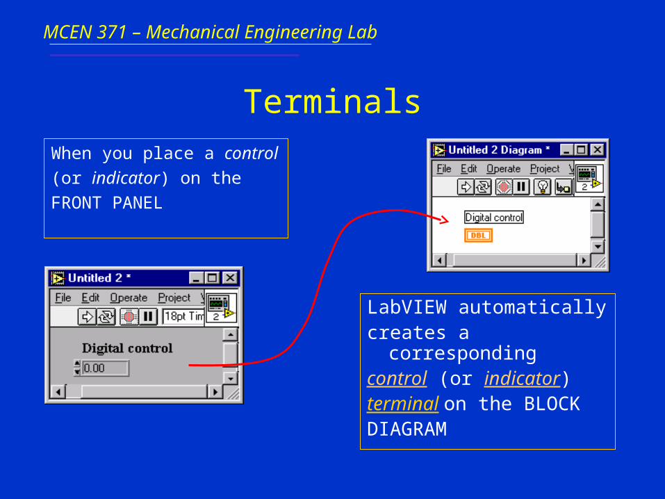
Terminals
When you place a control
(or indicator) on the
FRONT PANEL
LabVIEW automatically creates a correspondingcontrol (or indicator) terminal on the BLOCKDIAGRAM
MCEN 371 – Mechanical Engineering Lab
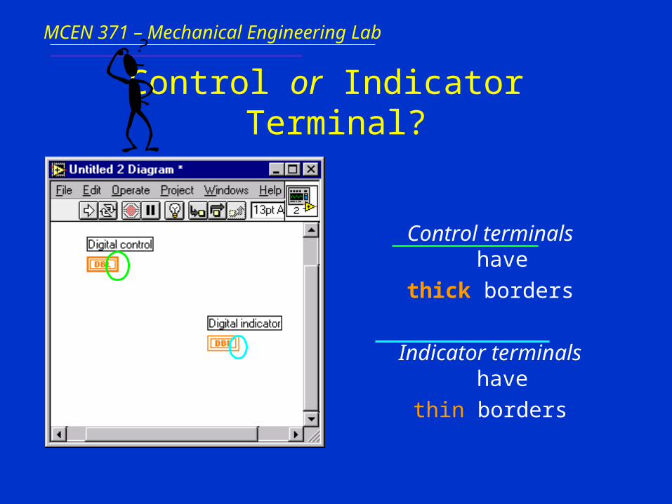
Control or Indicator Terminal?
Control terminals have
thick borders
Indicator terminals have
thin borders

MCEN 371 – Mechanical Engineering Lab
Deleting Block Diagram Terminals
• By default, you cannot delete a block diagram terminal that belongs to a control (or indicator).
• The terminal disappears only when you delete its corresponding control (or indicator) on the FRONT PANEL.
MCEN 371 – Mechanical Engineering Lab
Nodes
Node is just a fancy word for a program execution element –
Nodes are analogous to statements, operators, functions and
subroutines in standard programming language:
• The add and subtract functions represent one type of node.
• A structure is an other type of node. Structures can execute code repeatedly or conditionally, similar to loops and case statements in traditional programming languages.
• LabVIEW has also special nodes, called formula nodes, which are useful for evaluating mathematical formulas or expressions.

MCEN 371 – Mechanical Engineering Lab
Wires
A LabVIEW VI is held together by wires connecting nodes
and terminals; they deliver data from one source terminal to
one or more destination terminals.
MCEN 371 – Mechanical Engineering Lab
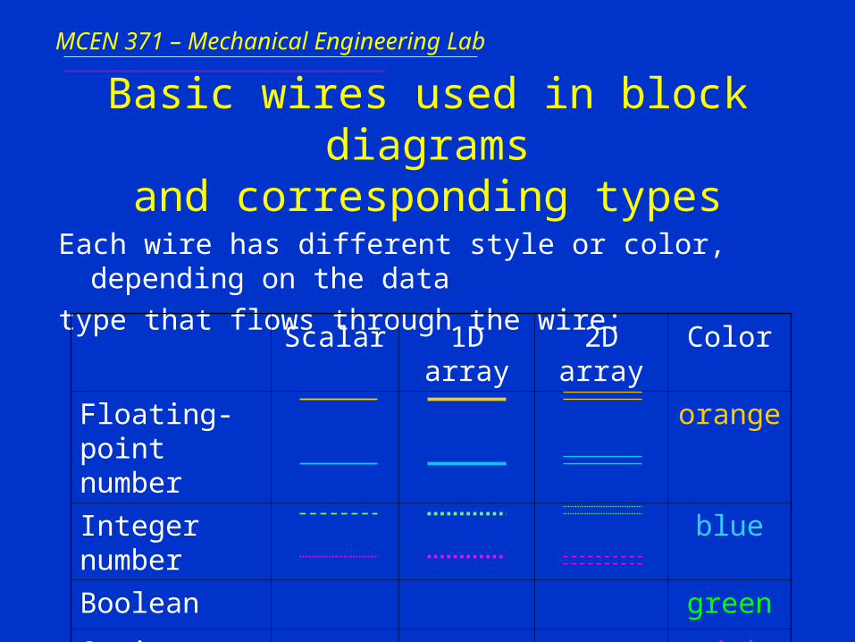
Basic wires used in block diagramsand corresponding types
Each wire has different style or color, depending on the data
type that flows through the wire:
Scalar 1D array 2D array Color
Floating-point number
orange
Integer number blue
Boolean green
String pink
MCEN 371 – Mechanical Engineering Lab
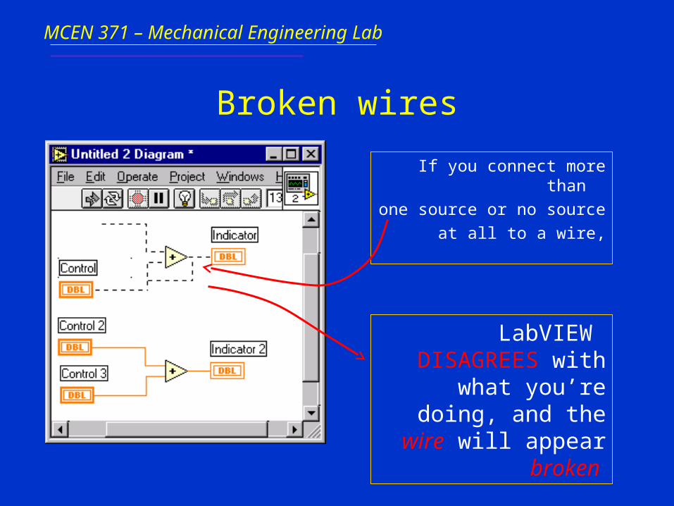
Broken wires
If you connect more than
one source or no source
at all to a wire,
LabVIEW DISAGREES with what
you’re doing, and thewire will appear broken

MCEN 371 – Mechanical Engineering Lab
Components of a block diagram –– Review ! ––
• Nodes: program execution elements
• Terminals: Ports through which data passes between the block diagram and the front panel and between nodes of the block diagram
• Wires: Data paths between terminals

MCEN 371 – Mechanical Engineering Lab
Dataflow Programming – Goingwith the flow
• Stated simply, a node executes only when data arrives at all its input terminals;
• the nodes supplies data to all of its output terminals when it finishes executing;
• and the data pass immediately from source to destination terminals.
MCEN 371 – Mechanical Engineering Lab
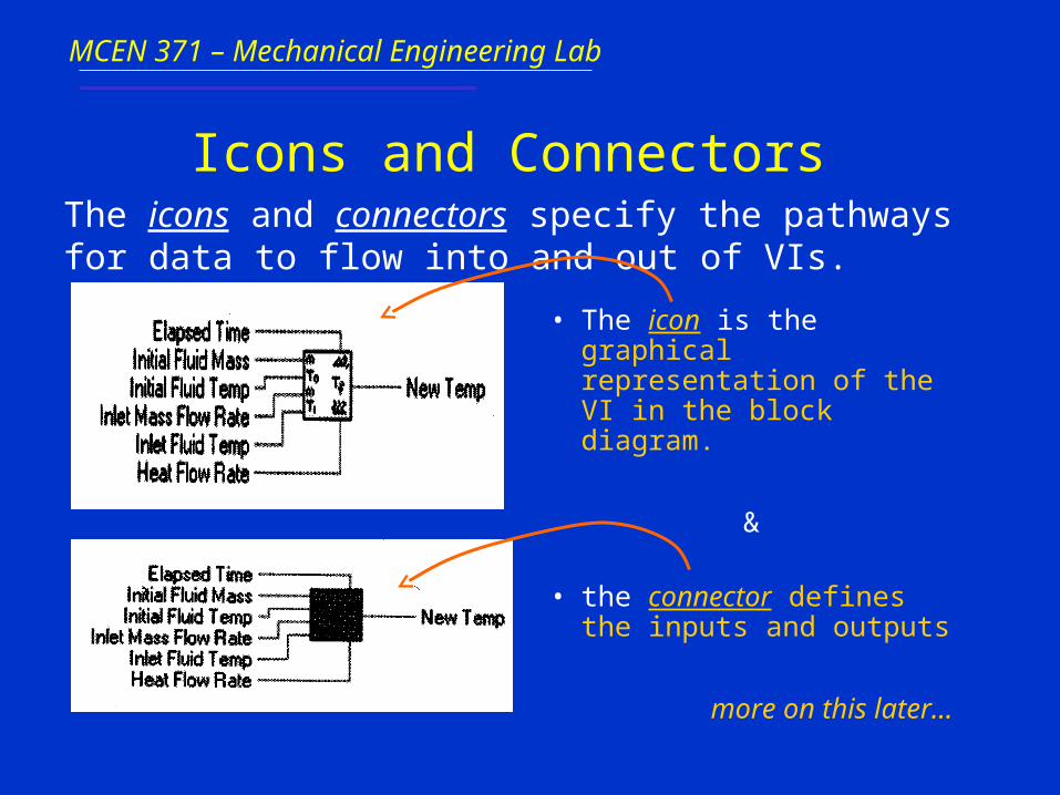
Icons and Connectors
• The icon is the graphical representation of the VI in the block diagram.
&
• the connector defines the inputs and outputs
The icons and connectors specify the pathways for data to flow into and out of VIs.
MCEN 371 – Mechanical Engineering Lab
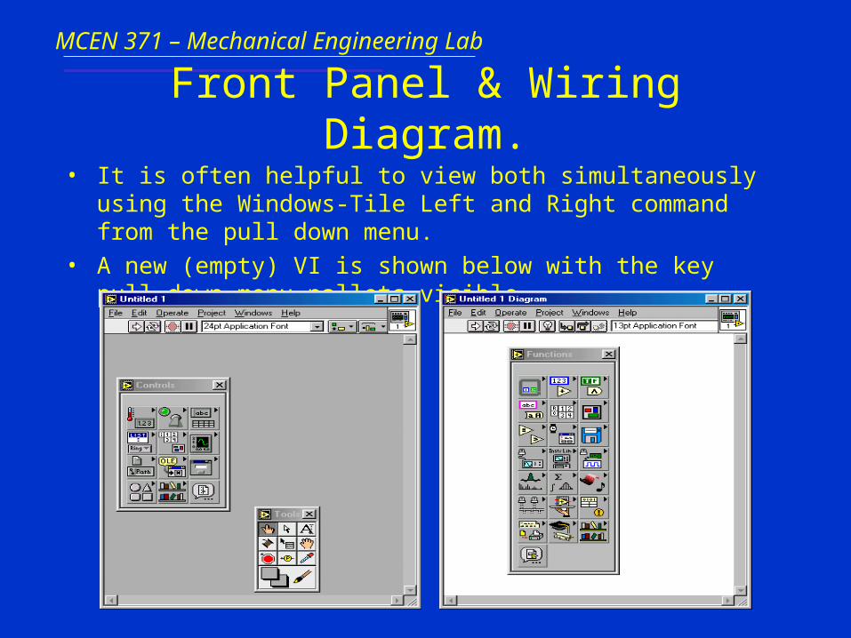
Front Panel & Wiring Diagram.
• It is often helpful to view both simultaneously using the Windows-Tile Left and Right command from the pull down menu.
• A new (empty) VI is shown below with the key pull-down menu pallets visible.

MCEN 371 – Mechanical Engineering Lab
Modifying a VI
• Only one of the two windows (front panel or wiring diagram) is active at any point in time. To activate one simply move the mouse over it and click a mouse button.
• To display any of the pallets (tools, controls, or functions) you can use the Windows pull down menu or simply left or right click your mouse.
• When you first pull up a pallet an image of a push pin is displayed in the upper left hand corner. Click on it to keep the pallet continuously displayed.
MCEN 371 – Mechanical Engineering Lab
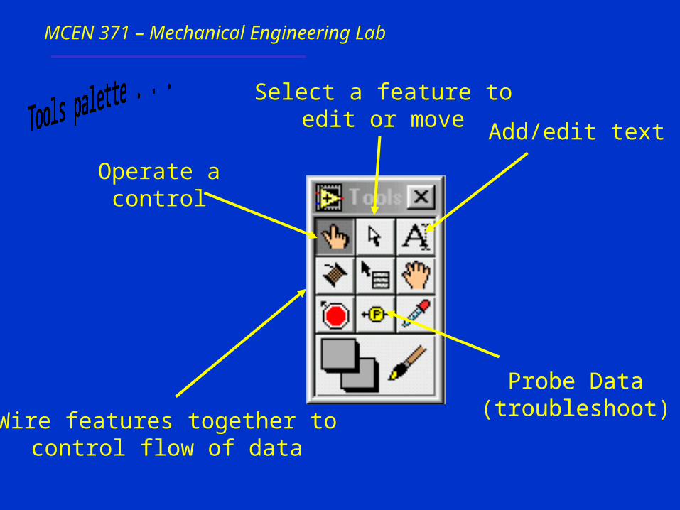
Add/edit text
Wire features together tocontrol flow of data
Select a feature toedit or move
Operate a control
Probe Data(troubleshoot)

MCEN 371 – Mechanical Engineering Lab
Insert a digital indicator or control
Insert a boolean control (button or switch)

MCEN 371 – Mechanical Engineering Lab
Add a structure such as for, while, and case statements
Add a numericoperator (+,-,…)
File I/O
Add a booleanoperator (and, or…)
Data Acquisition
Signal analysis
Comparison
Mathematical Functions
Timing/dialog

MCEN 371 – Mechanical Engineering Lab

MCEN 371 – Mechanical Engineering Lab
Reorder objects
Run
Continuous run
PauseStop
Font ring
Alignment ring
Distribution ring
Debugging featuresmore on this later…
MCEN 371 – Mechanical Engineering Lab
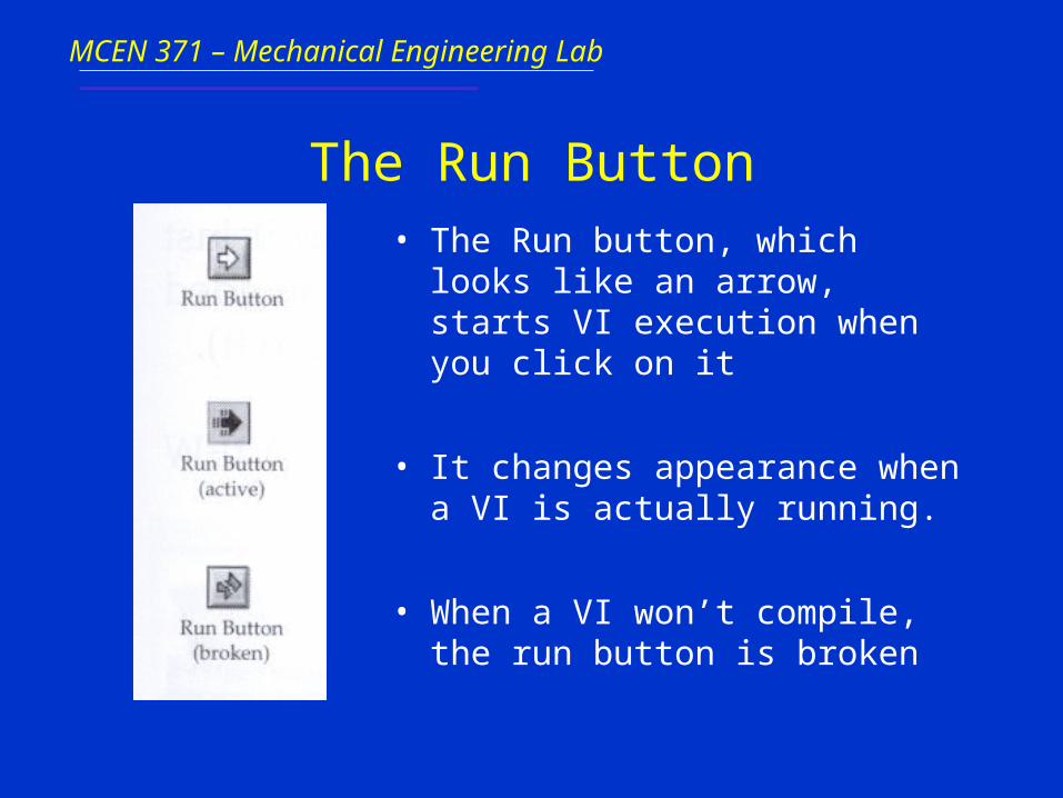
The Run Button• The Run button, which looks like an
arrow, starts VI execution when you click on it
• It changes appearance when a VI is actually running.
• When a VI won’t compile, the run button is broken
MCEN 371 – Mechanical Engineering Lab
Chapter 6: Chapter 6: LabVIEWLabVIEW
Part 3: Examples
MCEN 371 – Mechanical Engineering Lab
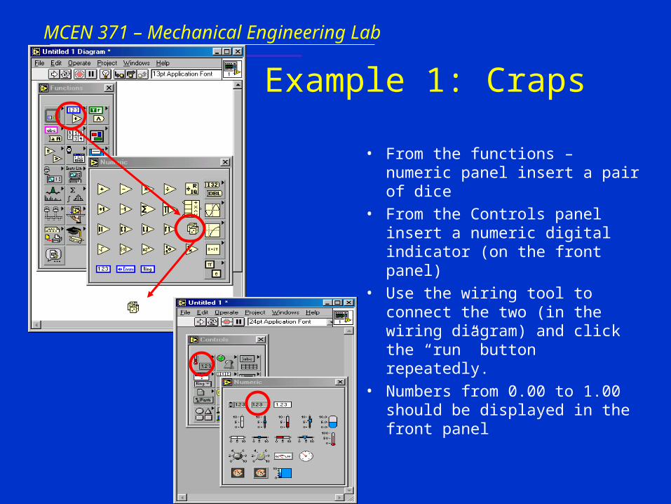
Example 1: Craps
• From the functions – numeric panel insert a pair of dice
• From the Controls panel insert a numeric digital indicator (on the front panel)
• Use the wiring tool to connect the two (in the wiring diagram) and click the “run” button repeatedly.
• Numbers from 0.00 to 1.00 should be displayed in the front panel
MCEN 371 – Mechanical Engineering Lab
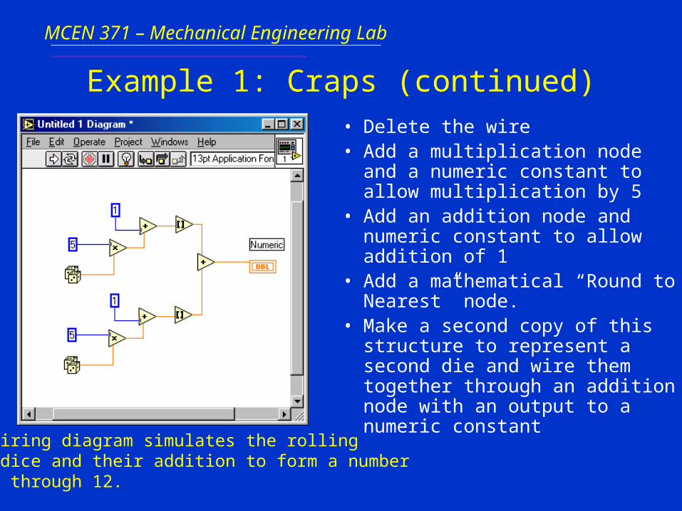
Example 1: Craps (continued)
• Delete the wire• Add a multiplication node and a
numeric constant to allow multiplication by 5
• Add an addition node and numeric constant to allow addition of 1
• Add a mathematical “Round to Nearest” node.
• Make a second copy of this structure to represent a second die and wire them together through an addition node with an output to a numeric constant This wiring diagram simulates the rolling
of 2 dice and their addition to form a numberfrom 2 through 12.
MCEN 371 – Mechanical Engineering Lab
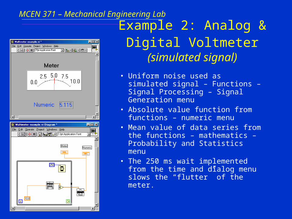
Example 2: Analog & Digital Voltmeter (simulated signal)
• Uniform noise used as simulated signal – Functions – Signal Processing – Signal Generation menu
• Absolute value function from functions – numeric menu
• Mean value of data series from the functions – mathematics – Probability and Statistics menu
• The 250 ms wait implemented from the time and dialog menu slows the “flutter” of the meter.
MCEN 371 – Mechanical Engineering Lab
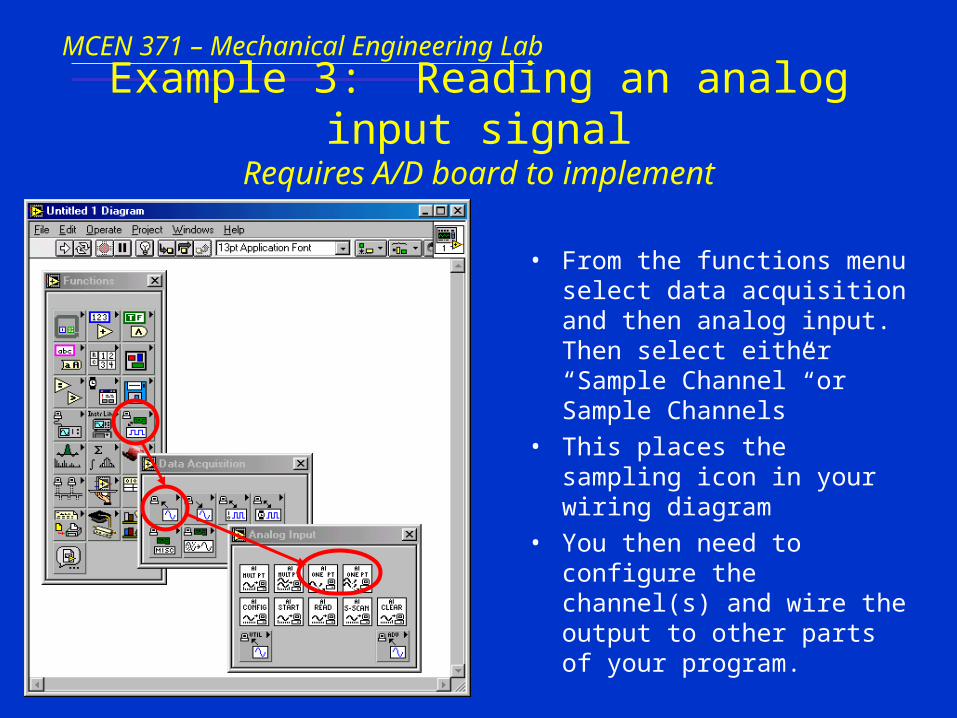
Example 3: Reading an analog input signalRequires A/D board to implement
• From the functions menu select data acquisition and then analog input. Then select either “Sample Channel” or Sample Channels”
• This places the sampling icon in your wiring diagram
• You then need to configure the channel(s) and wire the output to other parts of your program.

MCEN 371 – Mechanical Engineering Lab
Example 4: Signal Analysis (continued)
MCEN 371 – Mechanical Engineering Lab
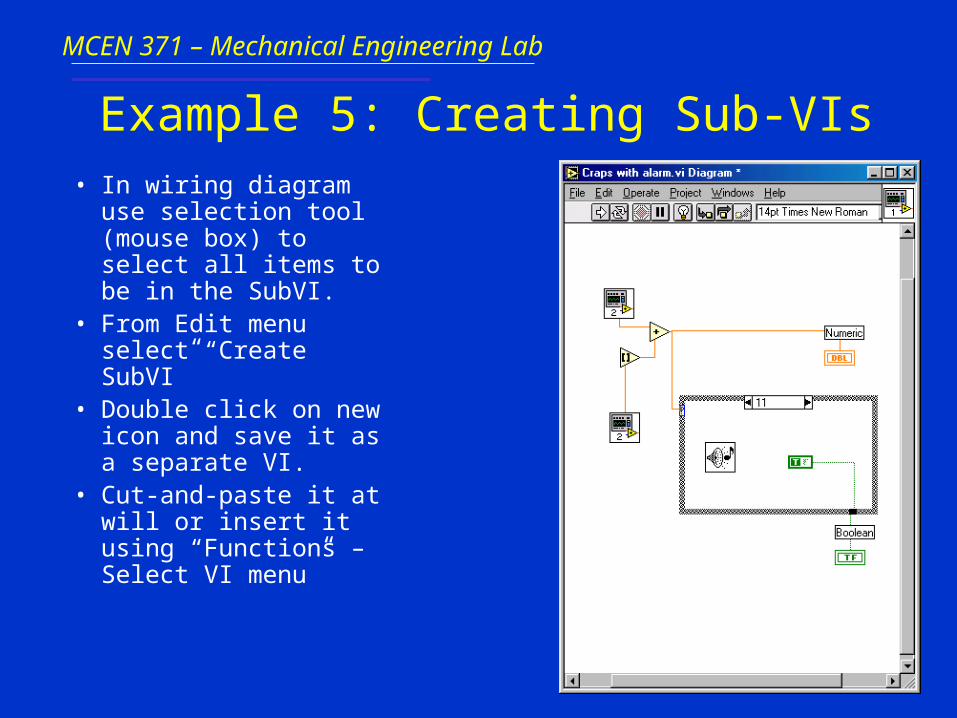
Example 5: Creating Sub-VIs• In wiring diagram use
selection tool (mouse box) to select all items to be in the SubVI.
• From Edit menu select “Create SubVI”
• Double click on new icon and save it as a separate VI.
• Cut-and-paste it at will or insert it using “Functions – Select VI menu”
Related Documents