Bulletin MM-856 McDonnell & Miller Service Guide Fast Facts Testing Tips Troubleshooting Proper Hook-ups ITT

mcdonmillservice
Oct 03, 2014
Mcdonnel-Miller service manual for some of the products.
Welcome message from author
This document is posted to help you gain knowledge. Please leave a comment to let me know what you think about it! Share it to your friends and learn new things together.
Transcript
Bulletin MM-856
McDonnell & MillerService
GuideFast Facts Testing Tips Troubleshooting Proper Hook-ups
ITT
2
McDonnell & Miller Service GuideIn this service guide, you will find many helpful tips concerning installation, maintenance and troubleshooting boiler controls.
It is intended to highlight factors that should be considered in boiler installation, operation, main-tenance, and servicing.
Only qualified individuals trained in accordance with all applicable codes should perform installa-tion and repair of boiler controls.
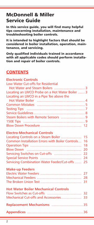
CONTENTS
Electronic ControlsLow Water Cut-offs for Residential Hot Water and Steam Boilers ……………………… 3Locating an LWCO Probe on a Hot Water Boiler …… 3 Locating an LWCO in a Pipe Tee above the Hot Water Boiler …………………………………… 4 Common Mistakes …………………………………… 5Testing Tips …………………………………………… 7Service Guidelines ……………………………………… 8Steam Boilers with Remote Sensors ………………… 9150E Tips ……………………………………………… 9Blow Down Procedure ……………………………… 12
Electro-Mechanical ControlsLocating Controls on a Steam Boiler ……………… 15Common Installation Errors with Boiler Controls … 16Operation Tips ……………………………………… 18Blow Down ………………………………………… 20Servicing Switches on Cut-offs …………………… 22Special Service Points ……………………………… 24Servicing Combination Water Feeder/Cut-offs …… 25
Make-up FeedersElectric Water Feeders ……………………………… 27Mechanical Feeders ………………………………… 28The Broken Union Test ……………………………… 31
Hot Water Boiler Mechanical ControlsFlow Switches as Cut-offs ………………………… 32Mechanical Cut-offs and Accessories ……………… 33
Replacement Mechanisms ……………………… 35
Appendices ………………………………………… 36
3
Electronic Controls
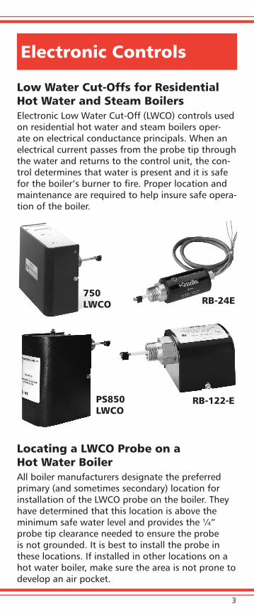
Low Water Cut-Offs for Residential Hot Water and Steam BoilersElectronic Low Water Cut-Off (LWCO) controls used on residential hot water and steam boilers oper-ate on electrical conductance principals. When an electrical current passes from the probe tip through the water and returns to the control unit, the con-trol determines that water is present and it is safe for the boiler’s burner to fire. Proper location and maintenance are required to help insure safe opera-tion of the boiler.
Locating a LWCO Probe on a Hot Water BoilerAll boiler manufacturers designate the preferred primary (and sometimes secondary) location for installation of the LWCO probe on the boiler. They have determined that this location is above the minimum safe water level and provides the ¼” probe tip clearance needed to ensure the probe is not grounded. It is best to install the probe in these locations. If installed in other locations on a hot water boiler, make sure the area is not prone to develop an air pocket.
RB-24E
PS850 LWCO
RB-122-E
750 LWCO
4
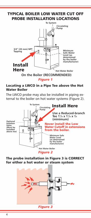
TYPICAL BOILER LOW WATER CUT OFF PROBE INSTALLATION LOCATIONS
Figure 1
Locating a LWCO in a Pipe Tee above the Hot Water BoilerThe LWCO probe may also be installed in piping ex-ternal to the boiler on hot water systems (Figure 2).
Figure 2
The probe installation in Figure 3 is CORRECT for either a hot water or steam system
Figure 3
InstallHere
On the Boiler (RECOMMENDED)Hot Water Boiler
MinimumSafe WaterLevel (asdeterminedby the boilermanufacturer)
CirculatingPump
To System
3/4” (20 mm) NPTTapping
Use a Reduced-branchTee 11/4 x 11/4 x 3/4(minimum)
Install Here
Hot Water Boiler
Minimum SafeWater Level(as determinedby the boilermanufacturer)
CirculatingPump
To System
OptionalIsolationValve(Must beinstalledabove tee)
Never install the LowWater Cutoff in extensionsfrom the boiler.
5
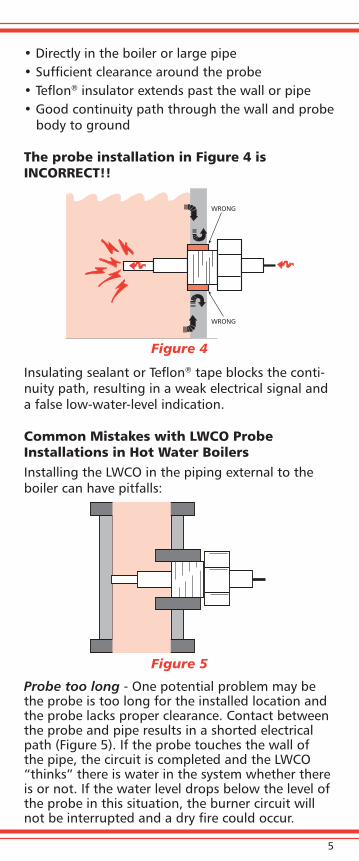
• Directly in the boiler or large pipe• Sufficient clearance around the probe• Teflon® insulator extends past the wall or pipe• Good continuity path through the wall and probe
body to ground
The probe installation in Figure 4 is INCORRECT!!
Figure 4
Insulating sealant or Teflon® tape blocks the conti-nuity path, resulting in a weak electrical signal and a false low-water-level indication.
Common Mistakes with LWCO Probe Installations in Hot Water BoilersInstalling the LWCO in the piping external to the boiler can have pitfalls:
Figure 5
Probe too long - One potential problem may be the probe is too long for the installed location and the probe lacks proper clearance. Contact between the probe and pipe results in a shorted electrical path (Figure 5). If the probe touches the wall of the pipe, the circuit is completed and the LWCO “thinks” there is water in the system whether there is or not. If the water level drops below the level of the probe in this situation, the burner circuit will not be interrupted and a dry fire could occur.
WRONG
WRONG
6
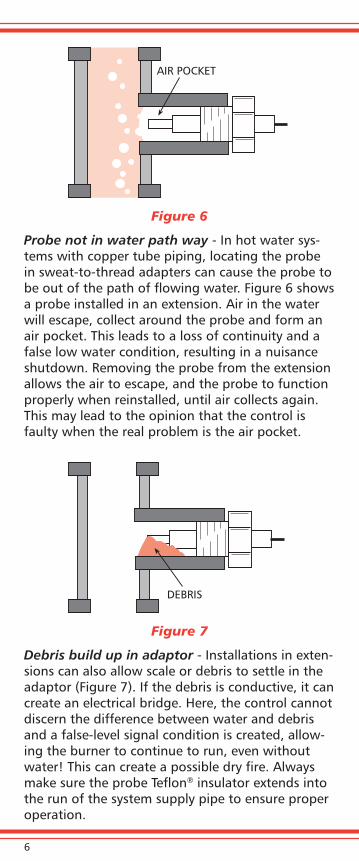
Figure 6
Probe not in water path way - In hot water sys-tems with copper tube piping, locating the probe in sweat-to-thread adapters can cause the probe to be out of the path of flowing water. Figure 6 shows a probe installed in an extension. Air in the water will escape, collect around the probe and form an air pocket. This leads to a loss of continuity and a false low water condition, resulting in a nuisance shutdown. Removing the probe from the extension allows the air to escape, and the probe to function properly when reinstalled, until air collects again. This may lead to the opinion that the control is faulty when the real problem is the air pocket.
Figure 7
Debris build up in adaptor - Installations in exten-sions can also allow scale or debris to settle in the adaptor (Figure 7). If the debris is conductive, it can create an electrical bridge. Here, the control cannot discern the difference between water and debris and a false-level signal condition is created, allow-ing the burner to continue to run, even without water! This can create a possible dry fire. Always make sure the probe Teflon® insulator extends into the run of the system supply pipe to ensure proper operation.
AIR POCKET
DEBRIS
7
Testing Tips for Series 750, PS-800, PSE-800 and PS-850 LWCO• On a regular schedule, perform an operational
test on the LWCO control while the system is run-ning.
• On controls with a TEST button, press and hold the button for at least 30 seconds. The electronic control will go into a low water cut-off condition and turn the system off.
• For steam systems, occasionally perform an actual low water test by draining the system to just below the probe level as it is running. This will determine whether the probe will sense the absence of water in the system. If the system has an electronic time delayed make-up water feeder, press and hold the test button for at least 2 min-utes to allow the feeder to actuate.
If the system fails to shut off during any of these tests, immediately turn off the boiler. Determine the reason for the failure and correct the problem. Failure to correct may result in serious property damage, personal injury or death.
Series PS800 and PS850 cut-offs manufactured prior to December 2007 have a shorted probe diagnostic feature. For controls with this feature, if the LWCO senses 5 ohms or less resistance levels between the probe and ground, the control shuts down the boiler and displays alternately-flashing-red-and-green LED’s. This indicates there is a prob-lem at the probe - the probe is in contact with or grounded to the boiler piping. Another possibility is boiler water chemistry. Aggressive cleaning agents in the boiler can affect the conductivity level and result in a nuisance shorted probe cut-off.

8
Service guidelines for steam or hot water applications with low water cut-off controls and probes
Inspect the probe annually or more frequently for scale build-up or oily residue, and clean or replace the probe if necessary. If the McDonnell & Miller probe has the patented self-cleaning feature, the inspection and cleaning is required only every five years, unless performance problems indicate more frequent cleaning is required.
• Check annually for damaged probe wire insula-tion or loose power wiring and grounding con-nections.
• Make certain there is no scale or build-up on the central metal probe rod or its Teflon® insulator.
• Clean the probe only by wiping with a non-abra-sive cloth and rinsing with clean water.
• Do not use sharp instruments to remove scale or rust accumulations.
• Be careful not to damage the Teflon insulator.
• Replace the probe if the Teflon insulator is cracked or the probe rod is loose in the assembly.
• Replace the probe every 10 years or more fre-quently if applications have significant water treatment or high make-up water requirements. Appendix B lists available replacement probes.
• Replace the low water cut-off control unit every 15 years.
9
External LEDs
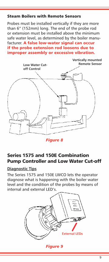
Steam Boilers with Remote Sensors
Probes must be installed vertically if they are more than 6” (152mm) long. The end of the probe rod or extension must be installed above the minimum safe water level, as determined by the boiler manu-facturer. A false low-water signal can occur if the probe extension rod loosens due to improper assembly or excessive vibration.
Figure 8
Series 1575 and 150E Combination Pump Controller and Low Water Cut-off Diagnostic TipsThe Series 1575 and 150E LWCO lets the operator diagnose what is happening with the boiler water level and the condition of the probes by means of internal and external LED’s.
Figure 9
Low Water Cut-off Control
Vertically mountedRemote Sensor
10
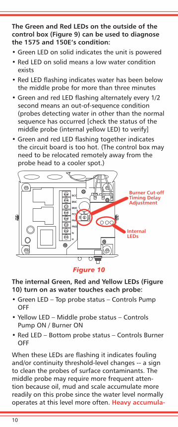
The Green and Red LEDs on the outside of the control box (Figure 9) can be used to diagnose the 1575 and 150E’s condition:• Green LED on solid indicates the unit is powered • Red LED on solid means a low water condition
exists• Red LED flashing indicates water has been below
the middle probe for more than three minutes• Green and red LED flashing alternately every 1/2
second means an out-of-sequence condition (probes detecting water in other than the normal sequence has occurred [check the status of the middle probe (internal yellow LED) to verify]
• Green and red LED flashing together indicates the circuit board is too hot. (The control box may need to be relocated remotely away from the probe head to a cooler spot.)
Figure 10
The internal Green, Red and Yellow LEDs (Figure 10) turn on as water touches each probe:• Green LED – Top probe status – Controls Pump
OFF• Yellow LED – Middle probe status – Controls
Pump ON / Burner ON• Red LED – Bottom probe status – Controls Burner
OFF
When these LEDs are flashing it indicates fouling and/or continuity threshold-level changes -- a sign to clean the probes of surface contaminants. The middle probe may require more frequent atten-tion because oil, mud and scale accumulate more readily on this probe since the water level normally operates at this level more often. Heavy accumula-
BCC
BNC
BNO
PCC
PNC
PNO
N
H
30
60
Secs
.
Burner Cut-offTiming DelayAdjustment
InternalLEDs
11
tions of scale may result in an out-of-sequence shut down due to fouling of the middle or lower probe.
The 1575 and 150E control also has a Burner Cut-off Timing Delay Adjustment (Figure 10). If the factory-set, zero delay is too short, make changes in small increments. Test the boiler cut-off after each setting change. While pressing the “TEST” button, the external green LED will flash once per second of time delay.
As with all remotely-mounted electronic controls, proper grounding techniques should be followed. Always run a separate ground wire from the con-trol box to the sensor body for best operation.
CAUTION: In applications that require high vol-ume make-up water, scaling of the probes and internal chamber surfaces becomes a problem.
Proper, Periodic Blow downs Are RequiredPeriodic flushing of the control, referred to as blow down, is an essential component of an effective boiler maintenance program. The purposes of a blow down test are to verify proper control opera-tion and to clear the LWCO chamber of sediment and debris. Sediment or debris in the chamber and on the probes may cause the probe(s) to incor-rectly sense the water level due to accumulation of deposits that can affect probe conductivity.
Blow downs must be done while the boiler is operating. The frequency of LWCO blow down is determined by the operating pressure of the boiler:• Daily, if the boiler operating pressure is above 15
psi• Weekly, if the boiler operating pressure is below
15 psi• Primary and secondary controls should be blown
down independently
NOTE: More frequent blow down may be neces-sary due to dirty boiler water and/or local code requirements.
12
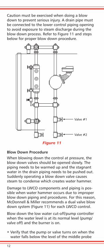
Caution must be exercised when doing a blow down to prevent serious injury. A drain pipe must be connected to the lower control piping opening to avoid exposure to steam discharge during the blow down process. Refer to Figure 11 and steps below for proper blow down procedure.
Figure 11
Blow Down ProcedureWhen blowing down the control at pressure, the blow down valves should be opened slowly. The piping needs to be warmed up and the stagnant water in the drain piping needs to be pushed out. Suddenly operating a blow down valve causes steam to condense which creates water hammer.
Damage to LWCO components and piping is pos-sible when water hammer occurs due to improper blow down piping and procedures. For this reason, McDonnell & Miller recommends a dual valve blow down system (Figure 11) for each LWCO control.
Blow down the low water cut-off/pump controller when the water level is at its normal level (pump/valve off) and the burner is on.
• Verify that the pump or valve turns on when the water falls below the level of the middle probe
Valve #1
Valve #2
13
• Verify that the burner turns off when the water level falls below the level of the bottom probe and is still visible in the sight glass
• Slowly close the lower “Throttling Gate Valve” (#2). The water level should begin to rise:
• Verify that the burner turns on when the water level reaches the middle probe level
• Verify the pump or valve turns off when the water level rises above the top probe position.
If the above sequence of actions does not occur as described, immediately close all valves, turn off the boiler and correct the problem. Inspec-tion/cleaning of the LWCO probes by disman-tling the control may be required.
If the LWCO performs per these instructions, close both blow down valves and return boiler to normal operation.
Periodic LWCO Dismantle Inspections are Required
At least annually, disassembly, inspection and cleaning of the LWCO components and piping are required.• During the inspection/cleaning, the float bowl/
probe chamber and equalizing piping must be examined and cleaned to ensure all sediment or debris is removed.
• The LWCO/pump control unit should be replaced if it is worn, corroded, or if components no lon-ger operate properly.
• Inspect the probe for scale build-up or oily resi-due and clean or replace if necessary.
• Check for damaged probe wire insulation or loose power wiring and grounding connections.
• Make certain there is no scale or build-up on the central metal probe rod or its Teflon® insulator.
• Clean the probe only by wiping with a non-abra-sive cloth and rinsing with clean water.
• Do not use sharp instruments to remove scale or rust accumulations.
• Be careful not to damage the Teflon insulator.• Replace the probe flange assembly if the Teflon
insulator on any probe is cracked or the probe rod is loose in the assembly.

14
• Replace the probe assembly every 10 years, or more frequently if applications have significant water treatment or high make-up water require-ments.
• Replace the low water cut-off control unit every 15 years.
NOTEThe probes may need to be inspected and cleaned more frequently on systems where there is the potential of coating build-up on the probes. This includes systems:
• With high quantities of raw water make-up
• With no condensate return
• With untreated boiler water
• With inconsistent or infrequent boiler-water chemical treatment
• Where significant changes have been made to the boiler-water chemical treatment process
• With oil in the boiler water
Excessive scale or sludge should trigger a reassess-ment of boiler water treatment, as well as more frequent dismantle inspections of the LWCO.
See the Installation and Maintenance Bulletins for full explanation of operation and test procedures:
Series 1575 – MM-286Series 150E – MM-414
Electro-Mechanical LWCO Controls
Float-Actuated Burner Switches and Feeder ValvesElectro-Mechanical LWCO controls use a float to monitor the water level in the boiler to determine if it is safe for the boiler’s burner to fire. Proper loca-tion and maintenance are required to help insure safe operation of the boiler.

15
Locating Controls on a Steam BoilerElectro-Mechanical controls include Low Water Cut-Offs (LWCO) and combination LWCO with feeder valves or pump controllers. Check to be sure that the cut-off/feeder is correctly installed before check-ing control function. Some controls are mounted in the gauge glass tappings (Figure 12); others are mounted in equalizing piping (Figure 13).
Figure 12
Figure 13
MODEL 63LOW WATERCUT-OFF
CUT-OFFLEVEL
1” WATEREQUALIZING PIPE
1” BLOW DOWNVALVE
INDEPENDENTWATER COLUMN
1” STEAMEQUALIZING PIPE
16
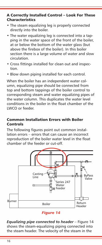
A Correctly Installed Control – Look For These Characteristics• The steam equalizing leg is properly connected
directly into the boiler.• The water equalizing leg is connected into a tap-
ping in the water space of the front of the boiler, at or below the bottom of the water glass (but above the firebox of the boiler). In this boiler section there is a large volume of water and slow circulation.
• Cross fittings installed for clean out and inspec-tion.
• Blow down piping installed for each control.
When the boiler has an independent water col-umn, equalizing pipe should be connected from top and bottom tappings of the boiler control to corresponding steam and water equalizing pipes of the water column. This duplicates the water level conditions in the boiler in the float chamber of the LWCO or feeder.
Common Installation Errors with Boiler ControlsThe following figures point out common instal-lation errors – errors that can cause an incorrect reproduction of the boiler water level in the float chamber of the feeder or cut-off.
Figure 14
Equalizing pipe connected to header – Figure 14 shows the steam-equalizing piping connected into the steam header. The velocity of the steam in the
ByPassValve
ReturnHeader
Series 247WaterFeeder
CastingLine
BurnerBoiler
17
larger line causes water level in float chamber to be higher than boiler water level.
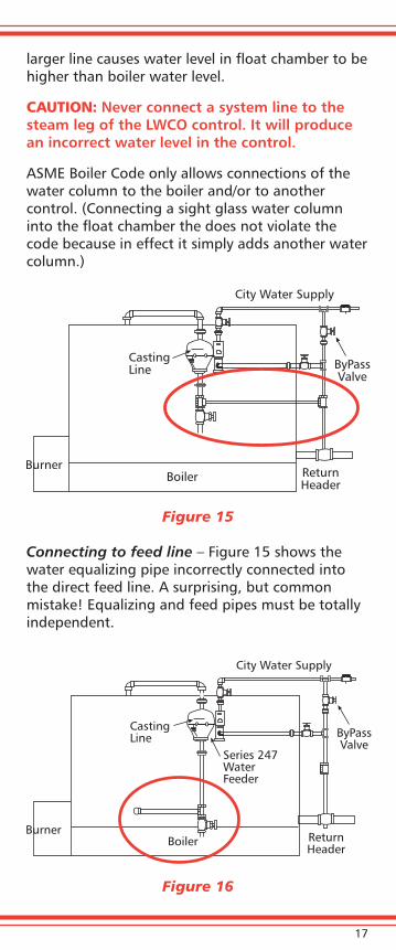
CAUTION: Never connect a system line to the steam leg of the LWCO control. It will produce an incorrect water level in the control.
ASME Boiler Code only allows connections of the water column to the boiler and/or to another control. (Connecting a sight glass water column into the float chamber the does not violate the code because in effect it simply adds another water column.)
Figure 15
Connecting to feed line – Figure 15 shows the water equalizing pipe incorrectly connected into the direct feed line. A surprising, but common mistake! Equalizing and feed pipes must be totally independent.
Figure 16
ByPassValve
ReturnHeader
CastingLine
BurnerBoiler
City Water Supply
ByPassValve
ReturnHeader
CastingLine
BurnerBoiler
City Water Supply
Series 247WaterFeeder
18
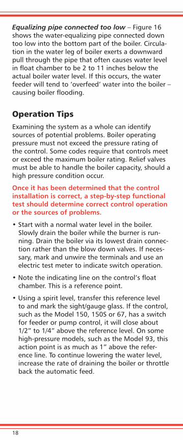
Equalizing pipe connected too low – Figure 16 shows the water-equalizing pipe connected down too low into the bottom part of the boiler. Circula-tion in the water leg of boiler exerts a downward pull through the pipe that often causes water level in float chamber to be 2 to 11 inches below the actual boiler water level. If this occurs, the water feeder will tend to ‘overfeed’ water into the boiler – causing boiler flooding.
Operation TipsExamining the system as a whole can identify sources of potential problems. Boiler operating pressure must not exceed the pressure rating of the control. Some codes require that controls meet or exceed the maximum boiler rating. Relief valves must be able to handle the boiler capacity, should a high pressure condition occur.
Once it has been determined that the control installation is correct, a step-by-step functional test should determine correct control operation or the sources of problems.
• Start with a normal water level in the boiler. Slowly drain the boiler while the burner is run-ning. Drain the boiler via its lowest drain connec-tion rather than the blow down valves. If neces-sary, mark and unwire the terminals and use an electric test meter to indicate switch operation.
• Note the indicating line on the control’s float chamber. This is a reference point.
• Using a spirit level, transfer this reference level to and mark the sight/gauge glass. If the control, such as the Model 150, 150S or 67, has a switch for feeder or pump control, it will close about 1/2” to 1/4” above the reference level. On some high-pressure models, such as the Model 93, this action point is as much as 1” above the refer-ence line. To continue lowering the water level, increase the rate of draining the boiler or throttle back the automatic feed.

19
• The most important point of action, the burner cut-off, should occur at the reference line, but no more than 1/2” below the reference line! ASME Boiler Code mandates there must be water still visible in the sight/gauge glass at the point of burner cut-off.
• Once the burner cut-off level has been reached and boiler cut-off has occurred, stop draining the boiler and slowly feed water into the boiler - up to the normal water level. The burner should re-start at a level about 1/2” to 3/4” above the cut-off level. The feeder or pump controller switch should not open before the burner switch closes, except on manual reset models. The manual reset units maintain burner cut-off until an adequate water level has been re-established in the boiler and a physical reset action occurs.
• If the stated actions do not occur as described, immediately turn off the boiler, investigate and correct the cause.
Periodic testing and consistent performance determines a control’s operation as a safety control.
Keep a log of the daily or weekly test of operation to track a control’s performance over time. The log will help identify changes in water conditions and component response time.
Whether the system has separate controls for low water cut-off and feeder/pump operation or all-in-one controls, the internal condition of the float chamber must be maintained free of sediment and debris for best performance. The Model 67 and 64 controls have float mechanism on the same plane as the switch mechanism. Sediment can ac-cumulate around and between the convolutions of the seal, or bellows of these controls. Over time, enough debris builds up affecting the movement of the control which delays or prohibits the reaction of the float to water level changes.
Proper and regular blow down of the control mini-mizes sediment accumulation.
In some cases, the debris can produce a physical obstruction to the mechanical action. Sediment around the float can also cause the float to dete-riorate and the float to take on water, resulting in
20
a false low water reaction and uncontrolled feeder/pump operation. Clean out of the chamber around the bellows using as gentle flushing water as pos-sible so as not to damage the thin bellows. If clean-ing is not practical, replacing the entire assembly is recommended.
LWCO Models 63, 42 or 150 have bellows which are above the waterline. These models are subject to floating debris and corrosive gases. An annual inspection is important to maximize control life. If the bellows develops a pinhole or fracture, steam and water leakage can cause significant damage to the electrical switch.
Changes of control set points should not be ig-nored. Replacement parts are available to bring the operation back to like-new condition.
Blow Down: A Key Maintenance PointPeriodic flushing of the control, referred to as blow down, is an essential component of an effective boiler maintenance program. The purposes of a blow down test are to verify proper control opera-tion and to clear the LWCO chamber of sediment and debris. Sediment or debris in the chamber may prevent the float from traveling through its normal operating range.
Blow downs must be done while the boiler is operating. The frequency of LWCO blow down is determined by the operating pressure of the boiler:
• Daily, if the boiler operating pressure is above 15 psi
• Weekly, if the boiler operating pressure is below 15 psi
• Primary and secondary controls should be blow down independently
NOTE: More frequent blow down may be neces-sary due to dirty boiler water and/or local code requirements.
Caution must be exercised when doing a blow down to prevent serious injury. A drain pipe must be connected to the lower control piping opening to avoid exposure to steam discharge during the blow down process. Refer to the illustration and steps below for proper blow down procedure.

21
Blow Down ProcedureWhen blowing down the control at pressure, the blow down valves should be opened slowly. The piping needs to be warmed up and the stagnant water in the drain piping needs to be pushed out. Suddenly operating a blow down valve causes steam to condense which creates water hammer.
Figure 17
Damage to LWCO components and piping is pos-sible when water hammer occurs due to improper blow down piping and procedures. For this reason, McDonnell & Miller recommends a dual valve blow down system (Figure 17) for each LWCO control.
Blow down the low water cut-off/pump controller when the water level is at its normal level (pump/valve off) and the burner is on.
• Open the upper “Positive Shut-off Valve” (#1)
• Slowly open the lower “Throttling Gate Valve” (#2)
• With both valves open, the water level in the control will drop in the sight glasso Verify that the pump switch contacts closeo Verify that the burner shuts off when water
falls to the cast-in low water cut-off line and is still visible in the sight glass
Valve #1
Valve #2

22
• Slowly close the lower “Throttling Gate Valve” (#2). The water level should begin to rise:o Verify the burner turns on when the water level
in the sight glass rises above the cast-in low water cut-off line
o Verify the pump turns off
If the above sequence of actions does not occur as described, immediately close all valves, turn off the boiler and correct the problem. Inspec-tion/cleaning of the LWCO float mechanism or probes by dismantling the control may be required.
If the LWCO performs per these instructions, close both blow down valves and return boiler to normal operation.
Series 47 and 67 Controls with 14B valves
Blow down the low water cut-off when the water level is at its normal level and the burner is on. Slowly open the blow down valve until it is fully open, and observe the water level falls in the gauge glass. After verifying the burner shuts off, close the valve. If the boiler does not shut off or restart as described, immediately shut off the boiler and cor-rect the problem.
Servicing Switches on the Cut-Off
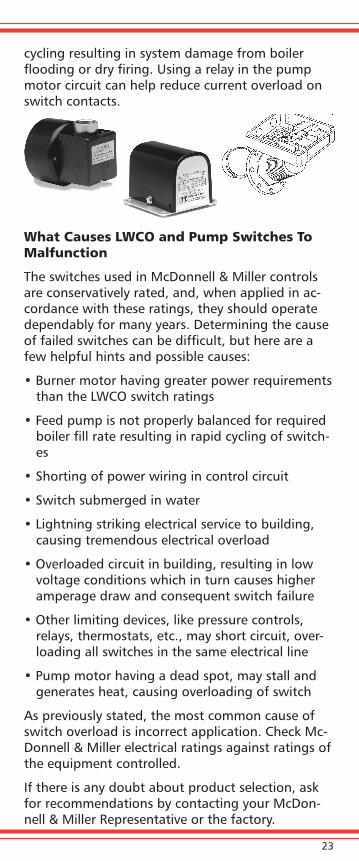
Electrical switches can deteriorate over time. In mercury switch units with glass tubes, dull, stretchy or separated mercury is a sign of aging. In snap switches, a visual examination provides little help. A continuity test must be performed to deter-mine whether a switch is functioning. Snap switch contacts can fuse from current overload or short
23
cycling resulting in system damage from boiler flooding or dry firing. Using a relay in the pump motor circuit can help reduce current overload on switch contacts.
What Causes LWCO and Pump Switches To Malfunction
The switches used in McDonnell & Miller controls are conservatively rated, and, when applied in ac-cordance with these ratings, they should operate dependably for many years. Determining the cause of failed switches can be difficult, but here are a few helpful hints and possible causes:
• Burner motor having greater power requirements than the LWCO switch ratings
• Feed pump is not properly balanced for required boiler fill rate resulting in rapid cycling of switch-es
• Shorting of power wiring in control circuit
• Switch submerged in water
• Lightning striking electrical service to building, causing tremendous electrical overload
• Overloaded circuit in building, resulting in low voltage conditions which in turn causes higher amperage draw and consequent switch failure
• Other limiting devices, like pressure controls, relays, thermostats, etc., may short circuit, over-loading all switches in the same electrical line
• Pump motor having a dead spot, may stall and generates heat, causing overloading of switch
As previously stated, the most common cause of switch overload is incorrect application. Check Mc-Donnell & Miller electrical ratings against ratings of the equipment controlled.
If there is any doubt about product selection, ask for recommendations by contacting your McDon-nell & Miller Representative or the factory.

24
Special Service PointsBoiler Piping Considerations
Figure 18
Make connections between boiler and control as short as possible, and make all piping not less than 1” pipe size. Always provide separate blow down valves in straightaway connection from each control and be sure there are no trapped discharge lines.
Figure 19
Pump Controller
X X
Feeder Cut-OffCombination
SteamBoiler
Pump Controller Feeder Cut-OffCombination
SteamBoiler
25
Improper water column piping may create a water pocket in the lower equalizing connections, as shown by the X’s in Figure 19. Such a water pocket often causes abnormal fluctuations when the control is blown down – particularly when boilers are operated above 100 PSI. This can subjected the floats to violent hammering with subsequent dam-age.
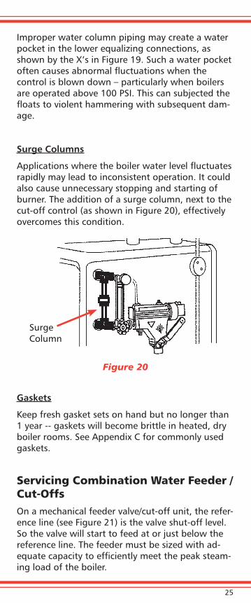
Surge Columns
Applications where the boiler water level fluctuates rapidly may lead to inconsistent operation. It could also cause unnecessary stopping and starting of burner. The addition of a surge column, next to the cut-off control (as shown in Figure 20), effectively overcomes this condition.
Figure 20
Gaskets
Keep fresh gasket sets on hand but no longer than 1 year -- gaskets will become brittle in heated, dry boiler rooms. See Appendix C for commonly used gaskets.
Servicing Combination Water Feeder / Cut-OffsOn a mechanical feeder valve/cut-off unit, the refer-ence line (see Figure 21) is the valve shut-off level. So the valve will start to feed at or just below the reference line. The feeder must be sized with ad-equate capacity to efficiently meet the peak steam-ing load of the boiler.
Surge Column

26
The burner cut-off level of these units is 3/4” to 1” below the reference line. To reach the cut-off level in testing this type of control, the feedwater supply should be throttled back while the boiler is slowly drained. If the cut-off level is too easily reached, there may be a blockage in the make-up water pip-ing or the feeder itself.
Once the cut-off level has been reached, stop drain-ing the boiler and allow the feeder to restore the water level. At 1/2” to 1/4” below the reference line, the burner switch should fire the burner on automatic switch models. Then the feeder valve will slowly close off until the water level is at or just above the reference line. On models with manual reset features, the burner cut-off switch should be reset when the water level in the sight glass reach-es the reference line.
IMPORTANT: When boiler water level fluctuates constantly causing the feeder to operate, this is a danger signal that the system needs atten-tion due to excessive feeding – even though the feeder has kept the boiler out of trouble. This could indicate the boiler has a leak or the sys-tem is losing condensate.
Figure 21
REFERENCE LINE
27
Make-up Feeders – Electric and Mechanical
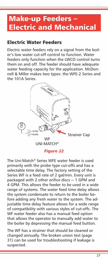
Electric Water FeedersElectric water feeders rely on a signal from the boil-er’s low water cut-off control to function. Water feeders only function when the LWCO control turns them on and off. The feeder should have adequate water feeding capacity for the application. McDon-nell & Miller makes two types: the WFE-2 Series and the 101A Series.
Figure 22
The Uni-Match® Series WFE water feeder is used primarily with the probe type cut-offs and has a selectable time delay. The factory setting of the Series WF is a feed rate of 2 gal/min. Every unit is packaged with 2 other orifice discs -- 1 GPM and 4 GPM. This allows the feeder to be used in a wide range of systems. The water feed time delay allows the system condensate to return to the boiler be-fore adding any fresh water to the system. The ad-justable time delay feature allows for a wide range of compatibility with various styles of cut-offs. The WF water feeder also has a manual feed option that allows the operator to manually add water to the boiler by depressing the manual feed button.
The WF has a strainer that should be cleaned or changed annually. The broken union test (page 31) can be used for troubleshooting if leakage is suspected.
Strainer CapWF
UNI-MATCH®

28
Figure 23
The series 101A is another electrical water feeder. This model has a replaceable valve cartridge, which should be removed, inspected, cleaned or replaced annually. NOTE: When removing and installing the cartridge from the valve body, depress and hold the manual feed button to remove added pressure on the cartridge seal.
Repeated or excessive on-off cycling of an electron-ic feeder will shorten its life dramatically. Examine the height of the red manual fill button above the cover (Figure 23). If it exceeds 5/8”, the linkage is wearing out or starting to lose adjustment. Just above the valve body are the access holes to the linkage adjustment. An adjustment can be made to reposition the linkage so that the height of the manual fill button is about 1/2”.
Mechanical FeedersMechanical feeders from M&M include the car-tridge valve design (Models 47, 247, 847, 51, 551 & 851) as well as the removable seat and stem design (Models 21, 221 & 25A). A basic and patented feature of the M&M Boiler Make-up Water Feeders is the “cool feed valve”. It is designed to operate “cool” to prevent water at the valve from reaching the critical temperature at which lime and scale can form. Connecting it to a hot water line defeats this purpose. Scale can be precipitated from hot water,
Manual Feed
101A & Cartridge
Linkage adjustment access window
5/8” max.

29
causing the feed valve to stick. Cold water from city or regular, unsoftened source is best.
Models 47, 247, 51, 53 & 51S feeders have a bel-lows seal between the float chamber and the valve housing. Frequent cycling or rapid level fluctuations in these models can cause premature failure and an external leak. Regardless of the type of make-up feeder, an annual inspection and cleaning is re-quired. The strainers at the inlet line should always be cleaned or replaced annually.
Adequate Water Feeding Capacity
Too often feeders have been selected based on the size of the water supply pipe. Remember that it is the opening size of the orifice in the feeder that determines the feeder capacity. Feeding capacity tables of McDonnell & Miller Boiler Water Feeders are found in the General Catalog MM-825. These capacities were determined under rated water sup-ply pressure and boiler pressure conditions.
If Boiler Is Getting Too Little Water
Reasons for too little water include:• A plugged strainer may prevent water flow • Priming and foaming due to dirty boiler water• Condensate hung up in system• Faulty operation of boiler feed pumps• City water pressures less than boiler pressure• Faulty swing-check in return header (allowing
water to be pushed out into return)
On float-controlled feeders, the float chamber may be filled with sediment due to poor blow down. To verify this, open blow down valve under float chamber. With blow down valve open, if little or no water flows, you can assume the float chamber

30
is loaded with mud or sediment. The float cannot move far enough to open the valve fully. Remove, inspect, clean and replace, if required.
NOTE: Using a feeder/cut-off combination in process boilers, larger boilers, or boilers with low differential pressures, may result in a low water level. These types of applications can be better handled by an independent feeder and cut-off.
For boilers which have larger make-up needs, the closely set operating levels of a feeder/cut-off combination may stop the burner before the feeder has caught up with the make-up requirements. By using a separate feeder and a separate cut-off, operating levels can be set so that the feeders will feed at its maximum rate before the cut-off stops the burner.
If Boiler Is Getting Too Much Water
Common causes of flooding include:• Feeder pump not balanced to boiler requirements • Faulty swing-check in return header • Plugged equalizing pipe connection • Leaking tankless hot water coil in boiler • Attendant over-filling boiler through the hand
by-pass valve • Dirty water resulting in priming and carry-over• Too small difference between level of dry return
and boiler water level • City water pressure above 150 lbs. (May need
pressure reducing valve in feed line)
Faulty installation can cause flooding. Remember that the closing level of make-up feeders on heat-ing boilers should be set 2” to 2½ “ below the manufacturer’s recommended boiler water line. This allows the system return to properly balance varying steaming rates without adding make-up.
In all of these cases, perform a broken union test below to pinpoint or eliminate the feeder as the source of the problem.
31
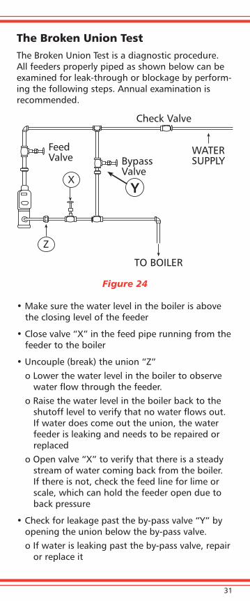
The Broken Union TestThe Broken Union Test is a diagnostic procedure. All feeders properly piped as shown below can be examined for leak-through or blockage by perform-ing the following steps. Annual examination is recommended.
Figure 24
• Make sure the water level in the boiler is above the closing level of the feeder
• Close valve “X” in the feed pipe running from the feeder to the boiler
• Uncouple (break) the union “Z” o Lower the water level in the boiler to observe
water flow through the feeder.o Raise the water level in the boiler back to the
shutoff level to verify that no water flows out. If water does come out the union, the water feeder is leaking and needs to be repaired or replaced
o Open valve “X” to verify that there is a steady stream of water coming back from the boiler. If there is not, check the feed line for lime or scale, which can hold the feeder open due to back pressure
• Check for leakage past the by-pass valve “Y” by opening the union below the by-pass valve.o If water is leaking past the by-pass valve, repair
or replace it
X
Z
Y
FeedValve Bypass
Valve
WATERSUPPLY
Check Valve
TO BOILER
32
HOT WATER BOILER MECHANICAL CONTROLS
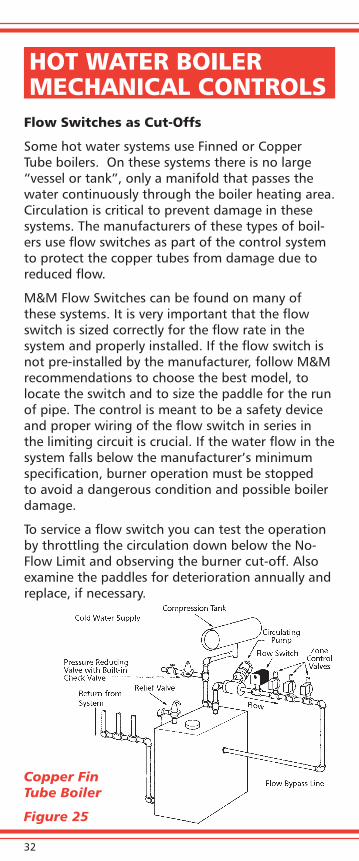
Flow Switches as Cut-Offs
Some hot water systems use Finned or Copper Tube boilers. On these systems there is no large “vessel or tank”, only a manifold that passes the water continuously through the boiler heating area. Circulation is critical to prevent damage in these systems. The manufacturers of these types of boil-ers use flow switches as part of the control system to protect the copper tubes from damage due to reduced flow.
M&M Flow Switches can be found on many of these systems. It is very important that the flow switch is sized correctly for the flow rate in the system and properly installed. If the flow switch is not pre-installed by the manufacturer, follow M&M recommendations to choose the best model, to locate the switch and to size the paddle for the run of pipe. The control is meant to be a safety device and proper wiring of the flow switch in series in the limiting circuit is crucial. If the water flow in the system falls below the manufacturer’s minimum specification, burner operation must be stopped to avoid a dangerous condition and possible boiler damage.
To service a flow switch you can test the operation by throttling the circulation down below the No-Flow Limit and observing the burner cut-off. Also examine the paddles for deterioration annually and replace, if necessary.
Copper Fin Tube Boiler
Figure 25
33
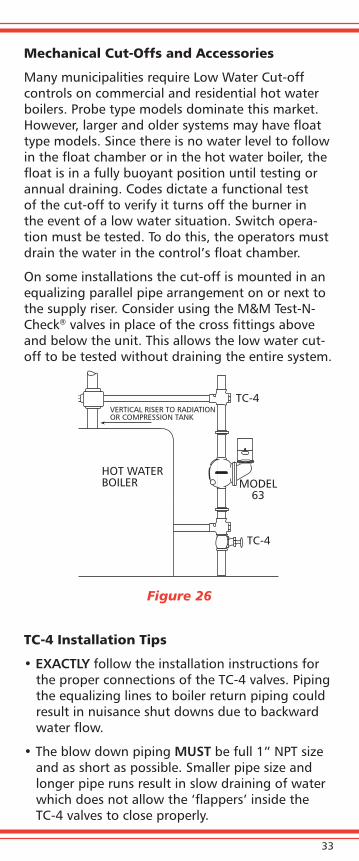
Mechanical Cut-Offs and Accessories
Many municipalities require Low Water Cut-off controls on commercial and residential hot water boilers. Probe type models dominate this market. However, larger and older systems may have float type models. Since there is no water level to follow in the float chamber or in the hot water boiler, the float is in a fully buoyant position until testing or annual draining. Codes dictate a functional test of the cut-off to verify it turns off the burner in the event of a low water situation. Switch opera-tion must be tested. To do this, the operators must drain the water in the control’s float chamber.
On some installations the cut-off is mounted in an equalizing parallel pipe arrangement on or next to the supply riser. Consider using the M&M Test-N-Check® valves in place of the cross fittings above and below the unit. This allows the low water cut-off to be tested without draining the entire system.
Figure 26
TC-4 Installation Tips
• EXACTLY follow the installation instructions for the proper connections of the TC-4 valves. Piping the equalizing lines to boiler return piping could result in nuisance shut downs due to backward water flow.
• The blow down piping MUST be full 1” NPT size and as short as possible. Smaller pipe size and longer pipe runs result in slow draining of water which does not allow the ‘flappers’ inside the TC-4 valves to close properly.
HOT WATERBOILER MODEL
63
TC-4
TC-4VERTICAL RISER TO RADIATIONOR COMPRESSION TANK
34
• Blow down valve should be ‘quick-opening’ type such as a lever-type ball valve. Using a slow-open-ing valve, such as a globe or gate valve, allows the boiler water to drain slowly while the valve is being opened and does not provide the required quick action for the ‘flappers’ in the TC-4 valves to open.
• When connecting the upper equalizing piping to the top of the boiler, install an air vent to the pip-ing to remove any accumulated air.
• The LWCO should ALWAYS be installed below the top of the boiler, but NEVER below the mini-mum safe water line recommended by the boiler manufacturer.
35
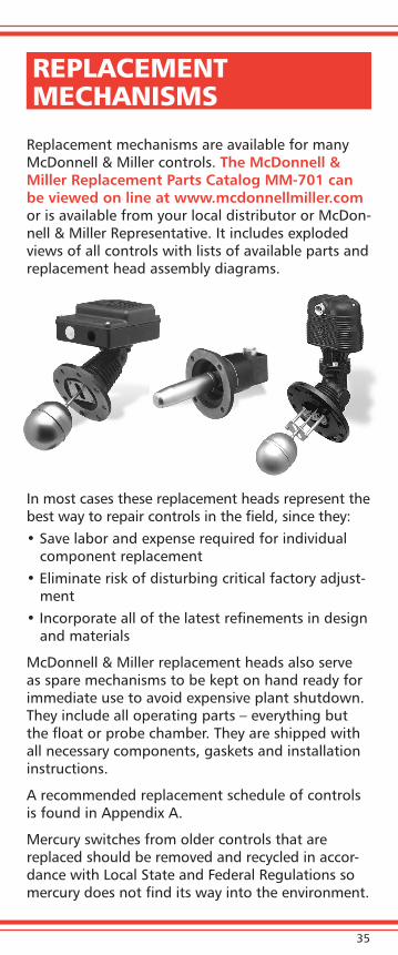
REPLACEMENT MECHANISMS
Replacement mechanisms are available for many McDonnell & Miller controls. The McDonnell & Miller Replacement Parts Catalog MM-701 can be viewed on line at www.mcdonnellmiller.com or is available from your local distributor or McDon-nell & Miller Representative. It includes exploded views of all controls with lists of available parts and replacement head assembly diagrams.
In most cases these replacement heads represent the best way to repair controls in the field, since they: • Save labor and expense required for individual
component replacement• Eliminate risk of disturbing critical factory adjust-
ment• Incorporate all of the latest refinements in design
and materials
McDonnell & Miller replacement heads also serve as spare mechanisms to be kept on hand ready for immediate use to avoid expensive plant shutdown. They include all operating parts – everything but the float or probe chamber. They are shipped with all necessary components, gaskets and installation instructions.
A recommended replacement schedule of controls is found in Appendix A.
Mercury switches from older controls that are replaced should be removed and recycled in accor-dance with Local State and Federal Regulations so mercury does not find its way into the environment.

36
APPENDIx A
Recommended Replacement Intervals - Low Water Cut-offs Recommended Recommended Series Maintenance Replacement Interval (max.) *150, 150S *157, 157S *158, 158S Blow down 15 years *159, 159S and test daily; 93, 193, inspect annually 94, 194 *42, 42S 10 years 67, 767, Blow down 61, 63, and test weekly; 10 years 64, 764 inspect annually 69, 169, Test and 269, 369, inspect annually 10 years 469, 569 750, PS-800, Test PSE-800, and PS-850, inspect 15 years 750B, annually RB120, RB122E RB24E Test and 10 years inspect annually 1575, Test daily and 15 years 150E inspect annually*Mercury Units are no longer available.
Replacement Head Mechanisms for Commercial/Industrial Applications Recommended Recommended Series Maintenance Replacement Interval (max.) *150-HD, 150S-HD, 93-HD, 94-HD, Test and 42-HD, 42S-HD, inspect annually 15 years 63-HD, 64-HD, 6667, 150E-HD
37
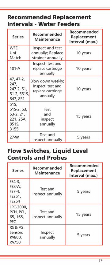
Recommended Replacement Intervals - Water Feeders Recommended Recommended Series Maintenance Replacement Interval (max.) WFE Inspect and test Uni- annually; Replace 10 years Match strainer annually Inspect, test and 101-A replace cartridge 10 years annually 47, 47-2, Blow down weekly; 247, Inspect, test and 247-2, 51, replace cartridge 10 years 51-2, 551S, annually 847, 851 51S, 51S-2, 53, Test 53-2, 21, and 15 years 221, 25A, inspect 851S, annually 3155 27-W Test and 5 years inspect annually
Flow Switches, Liquid Level Controls and Probes Recommended Recommended Series Maintenance Replacement Interval (max.) FS4-3, FS8-W, Test and FS7-4, inspect annually 5 years FS251, FS254 LPC-2000, PCH, PCL, Test and 15 years 65, 165, inspect annually PFC RS & AS Sensors Inspect 5 years PA800, annually PA750

38
APPENDIx B
Probe Assemblies
Model Where Used Replacement Probe
PS801, PS802, Residential PA-800 PS851, PS852 Steam and 354081 Hot Water
750P-MT-120 Commercial PA-800 Hot Water 354081
RB-120, Residential PA-RB-122 RB-122, Hot Water 354083 PS851-SP, PS852-SP
PS851- RX2, Commercial PA-800-RX2 PS802-RX2 and Residential 354140 Hot Water and Steam
PS801-U, Residential PA-800 -U PS802-U, Steam and 354141 PS851-U Hot Water
RS, Commercial EA-RS 750B-C, High Pressure 354401 1575 Steam PA-750-HP 176319
150E Commercial 150E High Pressure 310492 Steam (Flange/Probe Assembly)
For the most accurate replacement probe information, visit McDonnell & Miller website, www.mcdonnellmiller.com.

39
APPENDIx C
Common Gaskets
Model Where Used Gasket Part Number
47, 67 Blow Down 313200 Valve
47 Body, Upper 312700 and Lower
51, 51S, Body-Head 304100 53, 25A
61, 63, Body-Head 302600 64
61, 67, Float Flange- 318800 69 (old) Body
150, 157, Body-Head 325400 150S, 157S, (flat face 93, 193 head flange)
150, 157, Body-Head 325500 150S, 157S, (raised face 150E, 157E head flange)
94, 194 Body-Head 323300
21, 47, Flange 335400 851, 851S
For the most accurate replacement probe information, visit McDonnell & Miller website, www.mcdonnellmiller.com.

ITT8200 N. Austin Avenue
Morton Grove, IL 60053Phone: 847-966-3700
FAX: 847-983-5954www.mcdonnellmiller.com
3/09
Your Local Distributor / Representative
ITT