Integrator Guide MC70 Enterprise Digital Assistant

Welcome message from author
This document is posted to help you gain knowledge. Please leave a comment to let me know what you think about it! Share it to your friends and learn new things together.
Transcript
Integrator Guide
MC70 Enterprise Digital Assistant


MC70 Integrator Guide
72E-71768-01
Revision A
January 2006

© 2006 by Symbol Technologies, Inc. All rights reserved.
No part of this publication may be reproduced or used in any form, or by any electrical or mechanical means, without permission in writing from Symbol. This includes electronic or mechanical means, such as photocopying, recording, or information storage and retrieval systems. The material in this manual is subject to change without notice.
The software is provided strictly on an “as is” basis. All software, including firmware, furnished to the user is on a licensed basis. Symbol grants to the user a non-transferable and non-exclusive license to use each software or firmware program delivered hereunder (licensed program). Except as noted below, such license may not be assigned, sublicensed, or otherwise transferred by the user without prior written consent of Symbol. No right to copy a licensed program in whole or in part is granted, except as permitted under copyright law. The user shall not modify, merge, or incorporate any form or portion of a licensed program with other program material, create a derivative work from a licensed program, or use a licensed program in a network without written permission from Symbol. The user agrees to maintain Symbol’s copyright notice on the licensed programs delivered hereunder, and to include the same on any authorized copies it makes, in whole or in part. The user agrees not to decompile, disassemble, decode, or reverse engineer any licensed program delivered to the user or any portion thereof.
Symbol reserves the right to make changes to any software or product to improve reliability, function, or design.
Symbol does not assume any product liability arising out of, or in connection with, the application or use of any product, circuit, or application described herein.
No license is granted, either expressly or by implication, estoppel, or otherwise under any Symbol Technologies, Inc., intellectual property rights. An implied license only exists for equipment, circuits, and subsystems contained in Symbol products.
Symbol®, Spectrum One®, and Spectrum24® are registered trademarks of Symbol Technologies, Inc. Bluetooth® wireless technolooy is a registered trademark of Bluetooth SIG. Microsoft, Windows and ActiveSync are either registered trademarks or trademarks of Microsoft Corporation. Other product names mentioned in this manual may be trademarks or registered trademarks of their respective companies and are hereby acknowledged.
Symbol Technologies, Inc.One Symbol PlazaHoltsville, New York 11742-1300http://www.symbol.com
Patents
This product is covered by one or more of the patents listed on the website: www.symbol.com/patents.
Table of Contents
About This GuideIntroduction .................................................................................................................... ixDocumentation Set ........................................................................................................ ixConfigurations................................................................................................................ xChapter Descriptions ..................................................................................................... xiNotational Conventions.................................................................................................. xiRelated Documents and Software ................................................................................. xiiService Information ........................................................................................................ xii
Symbol Support Center............................................................................................ xiii
Chapter 1: Getting StartedIntroduction ................................................................................................................... 1-1Unpacking the EDA ....................................................................................................... 1-1Accessories ................................................................................................................... 1-2Getting Started .............................................................................................................. 1-3Installing and Removing the Main Battery .................................................................... 1-3
Installing the Main Battery ....................................................................................... 1-3Removing the Main Battery ..................................................................................... 1-4
Charging the Battery ..................................................................................................... 1-5Charging the Main Battery and Memory Backup Battery ........................................ 1-5Charging Spare Batteries ........................................................................................ 1-6Charging Temperature ............................................................................................ 1-6
Powering On the EDA ................................................................................................... 1-7Calibrating the Screen ............................................................................................ 1-7
Resetting the EDA ........................................................................................................ 1-7Performing a Warm Boot ........................................................................................ 1-7Performing a Cold Boot ........................................................................................... 1-7
Waking the EDA ............................................................................................................ 1-8Locking the EDA ........................................................................................................... 1-8SIM Card ....................................................................................................................... 1-9Removing the Screen Protector .................................................................................... 1-11
Chapter 2: AccessoriesIntroduction ................................................................................................................... 2-1
Cables ..................................................................................................................... 2-1Cradles .................................................................................................................... 2-1
iv MC70 Integrator Guide
Miscellaneous ......................................................................................................... 2-1Snap-on Modules .................................................................................................... 2-2
Headset ........................................................................................................................ 2-2Multi Media Card (MMC) / Secure Digital (SD) Card .................................................... 2-2Single Slot USB/Serial Cradle ...................................................................................... 2-3
Setup ....................................................................................................................... 2-4Charging the EDA Battery ....................................................................................... 2-5Charging the Spare Battery .................................................................................... 2-5Battery Charging Indicators .................................................................................... 2-5
Four Slot Ethernet Cradle ............................................................................................. 2-6Setup ....................................................................................................................... 2-7Daisychaining Cradles ............................................................................................ 2-7Ethernet Cradle Drivers .......................................................................................... 2-8Charging and Communication ................................................................................ 2-9LED Charging Indicators ......................................................................................... 2-9
Wall Mount Bracket ....................................................................................................... 2-10VCD7000 Vehicle Cradle .............................................................................................. 2-12
Requirements .......................................................................................................... 2-12Connector Ports ...................................................................................................... 2-12Mounting the Cradle ................................................................................................ 2-13Power Connection ................................................................................................... 2-14Serial Device Connection ........................................................................................ 2-16Charging the EDA Battery ....................................................................................... 2-17Charging the Spare Battery .................................................................................... 2-18Battery Charging Indicators .................................................................................... 2-18
Four Slot Spare Battery Charger .................................................................................. 2-20Battery Shim Installation ......................................................................................... 2-20Spare Battery Charging .......................................................................................... 2-21Battery Charging Indicators .................................................................................... 2-21
Magnetic Stripe Reader (MSR) ..................................................................................... 2-22Attaching and Removing the MSR .......................................................................... 2-22Using the MSR ....................................................................................................... 2-23
TRG7000 Trigger Handle ............................................................................................. 2-23Installing the Trigger Handle Cleat .......................................................................... 2-23Inserting the EDA into the Trigger Handle .............................................................. 2-24Removing the EDA ................................................................................................. 2-25Using a Cradle ........................................................................................................ 2-25
Cables ........................................................................................................................... 2-26Setup ....................................................................................................................... 2-27Battery Charging ..................................................................................................... 2-28LED Charge Indications .......................................................................................... 2-28Communication Setup ............................................................................................. 2-28
Chapter 3: ActiveSyncIntroduction ................................................................................................................... 3-1EDA Setup .................................................................................................................... 3-2Installing ActiveSync ..................................................................................................... 3-2Setting Up an ActiveSync Connection on the Host Computer ...................................... 3-3
Table of Contents v
Setting up a Partnership ......................................................................................... 3-4
Chapter 4: Application Deployment for Mobile 5.0Introduction ................................................................................................................... 4-1Security ......................................................................................................................... 4-1
Application Security ................................................................................................ 4-1Digital Signatures .................................................................................................... 4-1Device Management Security ................................................................................. 4-3Remote API Security ............................................................................................... 4-4
Packaging ..................................................................................................................... 4-4Deployment ................................................................................................................... 4-4
Installation Using ActiveSync .................................................................................. 4-4Installation Using Storage Card .............................................................................. 4-5Installation Using AirBEAM ..................................................................................... 4-5Image Update ......................................................................................................... 4-5Creating a Splash Screen ....................................................................................... 4-6
XML Provisioning .......................................................................................................... 4-6Creating an XML Provisioning File .......................................................................... 4-7XML Provisioning vs. RegMerge and Copy File ..................................................... 4-7
Storage ......................................................................................................................... 4-9Random Access Memory ........................................................................................ 4-9Persistent Storage .................................................................................................. 4-9Application Folder ................................................................................................... 4-10
System Configuration Manager .................................................................................... 4-10File Types ............................................................................................................... 4-10User Interface ......................................................................................................... 4-11File Deployment ...................................................................................................... 4-13
Rapid Deployment Client .............................................................................................. 4-13Rapid Deployment Window ..................................................................................... 4-13Scanning RD Bar Codes ......................................................................................... 4-14
AirBEAM Smart ............................................................................................................. 4-16AirBEAM Package Builder ...................................................................................... 4-16AirBEAM Smart Client ............................................................................................. 4-17Synchronizing with the Server ................................................................................ 4-23AirBEAM Staging .................................................................................................... 4-24
Symbol Mobility Developer Kits .................................................................................... 4-24
Chapter 5: WAN ConfigurationIntroduction ................................................................................................................... 5-1Quick Startup Steps ...................................................................................................... 5-1MC70 Service Verification ............................................................................................. 5-2
Ensuring Network Coverage ................................................................................... 5-2Configuring a GPRS Data Connection .................................................................... 5-3Establishing a Data Connection .............................................................................. 5-5Ending a GPRS Data Connection ........................................................................... 5-7
GPRS Settings .............................................................................................................. 5-8Phone ...................................................................................................................... 5-8
vi MC70 Integrator Guide
Services .................................................................................................................. 5-10Network ................................................................................................................... 5-14Phone Info ............................................................................................................... 5-17Band ........................................................................................................................ 5-17
Chapter 6: Wireless ApplicationsIntroduction ................................................................................................................... 6-1Signal Strength Icon ..................................................................................................... 6-2Turning the WLAN Radio On and Off ........................................................................... 6-2Find WLANs Application ............................................................................................... 6-3Profile Editor Wizard ..................................................................................................... 6-4
Profile ID ................................................................................................................. 6-4Operating Mode ...................................................................................................... 6-5Ad-Hoc .................................................................................................................... 6-7Authentication ......................................................................................................... 6-7Tunneled Authentication ......................................................................................... 6-8User Certificate Selection ....................................................................................... 6-9Server Certificate Selection .................................................................................... 6-10Credential Cache Options ....................................................................................... 6-12Password ................................................................................................................ 6-14Advanced Identity ................................................................................................... 6-14Encryption ............................................................................................................... 6-15IP Mode ................................................................................................................... 6-17IP Address Entry ..................................................................................................... 6-17Transmit Power ....................................................................................................... 6-19Battery Usage ......................................................................................................... 6-20Manage Profiles Application ................................................................................... 6-21
Wireless Status Application .......................................................................................... 6-24Signal Strength Window .......................................................................................... 6-25Current Profile Window ........................................................................................... 6-26IPv4 Status Window ................................................................................................ 6-27Wireless Log Window ............................................................................................. 6-29Versions Window .................................................................................................... 6-29
Wireless Diagnostics Application .................................................................................. 6-31ICMP Ping Window ................................................................................................. 6-31Trace Route Window .............................................................................................. 6-32Known APs Window ................................................................................................ 6-33
Options ......................................................................................................................... 6-34Operating Mode Filtering ........................................................................................ 6-34Regulatory Options ................................................................................................. 6-35Band Selection ........................................................................................................ 6-35System Options ....................................................................................................... 6-36Change Password ................................................................................................... 6-36Export ...................................................................................................................... 6-37
Cold Boot Persistence .................................................................................................. 6-38Registry Settings ........................................................................................................... 6-39Log On/Off Application .................................................................................................. 6-39
User Already Logged In .......................................................................................... 6-39
Table of Contents vii
No User Logged In .................................................................................................. 6-40
Chapter 7: Maintenance and TroubleshootingIntroduction ................................................................................................................... 7-1Maintaining the EDA ..................................................................................................... 7-1Troubleshooting ............................................................................................................ 7-2
EDA ......................................................................................................................... 7-2Bluetooth Connection .............................................................................................. 7-4Single Slot USB/Serial Cradle ................................................................................. 7-6Four Slot Ethernet Cradle ....................................................................................... 7-7Vehicle Cradle ......................................................................................................... 7-8Four Slot Spare Battery Charger ............................................................................ 7-8Cables ..................................................................................................................... 7-9Magnetic Stripe Reader .......................................................................................... 7-9
Trigger Handle .............................................................................................................. 7-10
Appendix A: Technical SpecificationsTechnical Specifications ............................................................................................... A-1MC70 Accessory Specifications .................................................................................... A-4COM Port Definitions .................................................................................................... A-7Pin-Outs ........................................................................................................................ A-7
Index

viii MC70 Integrator Guide
About This Guide
Chapter 2
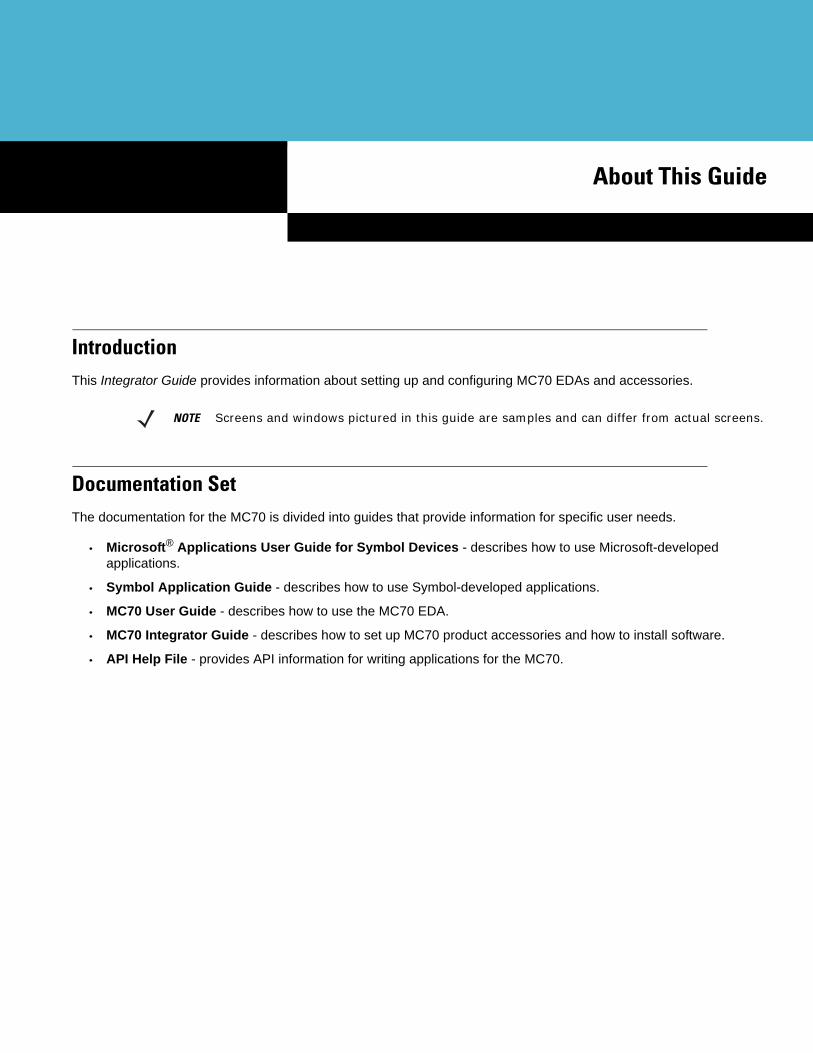
About This GuideIntroductionThis Integrator Guide provides information about setting up and configuring MC70 EDAs and accessories.
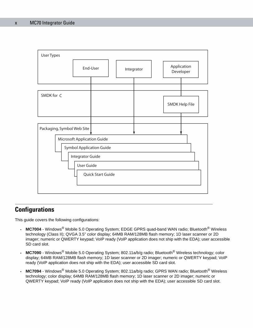
Documentation SetThe documentation for the MC70 is divided into guides that provide information for specific user needs.
• Microsoft® Applications User Guide for Symbol Devices - describes how to use Microsoft-developed applications.
• Symbol Application Guide - describes how to use Symbol-developed applications.
• MC70 User Guide - describes how to use the MC70 EDA.
• MC70 Integrator Guide - describes how to set up MC70 product accessories and how to install software.
• API Help File - provides API information for writing applications for the MC70.
NOTE Screens and windows pictured in this guide are samples and can differ from actual screens.
x MC70 Integrator Guide
ConfigurationsThis guide covers the following configurations:
• MC7004 - Windows® Mobile 5.0 Operating System; EDGE GPRS quad-band WAN radio; Bluetooth® Wireless technology (Class II); QVGA 3.5” color display; 64MB RAM/128MB flash memory; 1D laser scanner or 2D imager; numeric or QWERTY keypad; VoIP ready (VoIP application does not ship with the EDA); user accessible SD card slot.
• MC7090 - Windows® Mobile 5.0 Operating System; 802.11a/b/g radio; Bluetooth® Wireless technology; color display; 64MB RAM/128MB flash memory; 1D laser scanner or 2D imager; numeric or QWERTY keypad; VoIP ready (VoIP application does not ship with the EDA); user accessible SD card slot.
• MC7094 - Windows® Mobile 5.0 Operating System; 802.11a/b/g radio; GPRS WAN radio; Bluetooth® Wireless technology; color display; 64MB RAM/128MB flash memory; 1D laser scanner or 2D imager; numeric or QWERTY keypad; VoIP ready (VoIP application does not ship with the EDA); user accessible SD card slot.
About This Guide xi
Chapter DescriptionsTopics covered in this guide are as follows:
• Chapter 1, Getting Started provides information on EDA configurations and accessories, charging the battery, and resetting.
• Chapter 2, Accessories describes the accessories available for the EDA and how to set up power connections and battery charging capabilities, where applicable.
• Chapter 3, ActiveSync provides instructions on installing ActiveSync and setting up a partnership between the EDA and a host computer.
• Chapter 4, Application Deployment for Mobile 5.0 provides information for provisioning and deploying applications to the EDA.
• Chapter 5, WAN Configuration explains how to verify MC70 service on an Enhanced Data rates for Global Evolution (EDGE) wireless network and establish settings.
• Chapter 6, Wireless Applications describes how to configure the wireless LAN connection.
• Chapter 7, Maintenance and Troubleshooting includes instructions on cleaning and storing the EDA, and provides troubleshooting solutions for potential problems during EDA operation.
• Appendix A, Technical Specifications includes tables listing the technical specifications for the EDA and its accessories.
Notational ConventionsThe following conventions are used in this document:
• “EDA” refers to any Symbol terminal.
• Italics are used to highlight the following:
- chapters and sections in this and related documents
- dialog box, window, and screen names
- drop-down list and list box names
- check box and radio button names
- icons on a screen.
• Bold text is used to highlight the following:
- key names on a keypad
- button names on a screen.
• Bullets (•) indicate:
- action items
- lists of alternatives
- lists of required steps that are not necessarily sequential.
• Sequential lists (e.g., those that describe step-by-step procedures) appear as numbered lists.

xii MC70 Integrator Guide
Related Documents and SoftwareThe following documents provide more information about the MC70 EDAs.
• MC70 Quick Start Guide, p/n 72-71770-xx
• MC70 Microsoft Mobile 5.0 Regulatory Information, p/n 72-71767-xx
• MC70 User Guide, p/n 72E-71769-xx
• Microsoft® Applications for Mobile and CE 5.0 User Guide, p/n 72E-78456-xx
• Symbol Application Guide, p/n 72E-68901-xx
• Symbol Mobility Developer Kits (SMDKs), available at: http://devzone.symbol.com/
• Latest ActiveSync software, available at: http://www.microsoft.com.
For the latest version of this guide and all guides, go to: http://www.symbol.com/manuals.
Service InformationIf you have a problem with the equipment, contact the “Symbol Support Center,” for your region. See page xiii for contact information. Before calling, have the model number, serial number and several bar code symbols at hand.
Call the Support Center from a phone near the scanning equipment so that the service person can try to talk you through the problem. If the equipment is found to be working properly and the problem is symbol readability, the Support Center will request samples of bar codes for analysis at our plant.
If the problem cannot be solved over the phone, you may need to return the equipment for servicing. If that is necessary, you will be given specific directions.
NOTE Symbol Technologies is not responsible for any damages incurred during shipment if the approved shipping container is not used. Shipping the units improperly can possibly void the warranty. If the original shipping container was not kept, contact Symbol to have another sent to you.
About This Guide xiii
Symbol Support Center
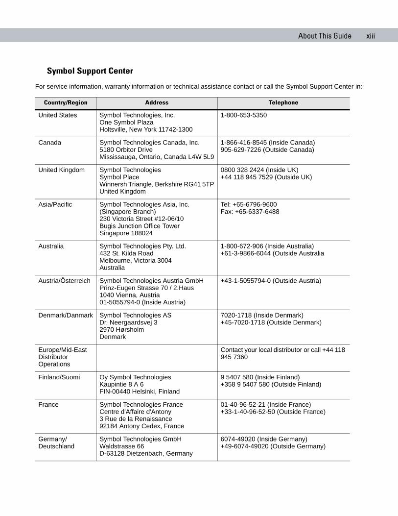
For service information, warranty information or technical assistance contact or call the Symbol Support Center in:
Country/Region Address Telephone
United States Symbol Technologies, Inc.One Symbol PlazaHoltsville, New York 11742-1300
1-800-653-5350
Canada Symbol Technologies Canada, Inc.5180 Orbitor DriveMississauga, Ontario, Canada L4W 5L9
1-866-416-8545 (Inside Canada)905-629-7226 (Outside Canada)
United Kingdom Symbol TechnologiesSymbol PlaceWinnersh Triangle, Berkshire RG41 5TPUnited Kingdom
0800 328 2424 (Inside UK)+44 118 945 7529 (Outside UK)
Asia/Pacific Symbol Technologies Asia, Inc. (Singapore Branch)230 Victoria Street #12-06/10Bugis Junction Office TowerSingapore 188024
Tel: +65-6796-9600 Fax: +65-6337-6488
Australia Symbol Technologies Pty. Ltd.432 St. Kilda RoadMelbourne, Victoria 3004Australia
1-800-672-906 (Inside Australia)+61-3-9866-6044 (Outside Australia
Austria/Österreich Symbol Technologies Austria GmbH Prinz-Eugen Strasse 70 / 2.Haus1040 Vienna, Austria01-5055794-0 (Inside Austria)
+43-1-5055794-0 (Outside Austria)
Denmark/Danmark Symbol Technologies ASDr. Neergaardsvej 32970 HørsholmDenmark
7020-1718 (Inside Denmark)+45-7020-1718 (Outside Denmark)
Europe/Mid-East Distributor Operations
Contact your local distributor or call +44 118 945 7360
Finland/Suomi Oy Symbol TechnologiesKaupintie 8 A 6FIN-00440 Helsinki, Finland
9 5407 580 (Inside Finland)+358 9 5407 580 (Outside Finland)
France Symbol Technologies FranceCentre d'Affaire d'Antony3 Rue de la Renaissance92184 Antony Cedex, France
01-40-96-52-21 (Inside France)+33-1-40-96-52-50 (Outside France)
Germany/Deutschland
Symbol Technologies GmbHWaldstrasse 66D-63128 Dietzenbach, Germany
6074-49020 (Inside Germany)+49-6074-49020 (Outside Germany)
xiv MC70 Integrator Guide
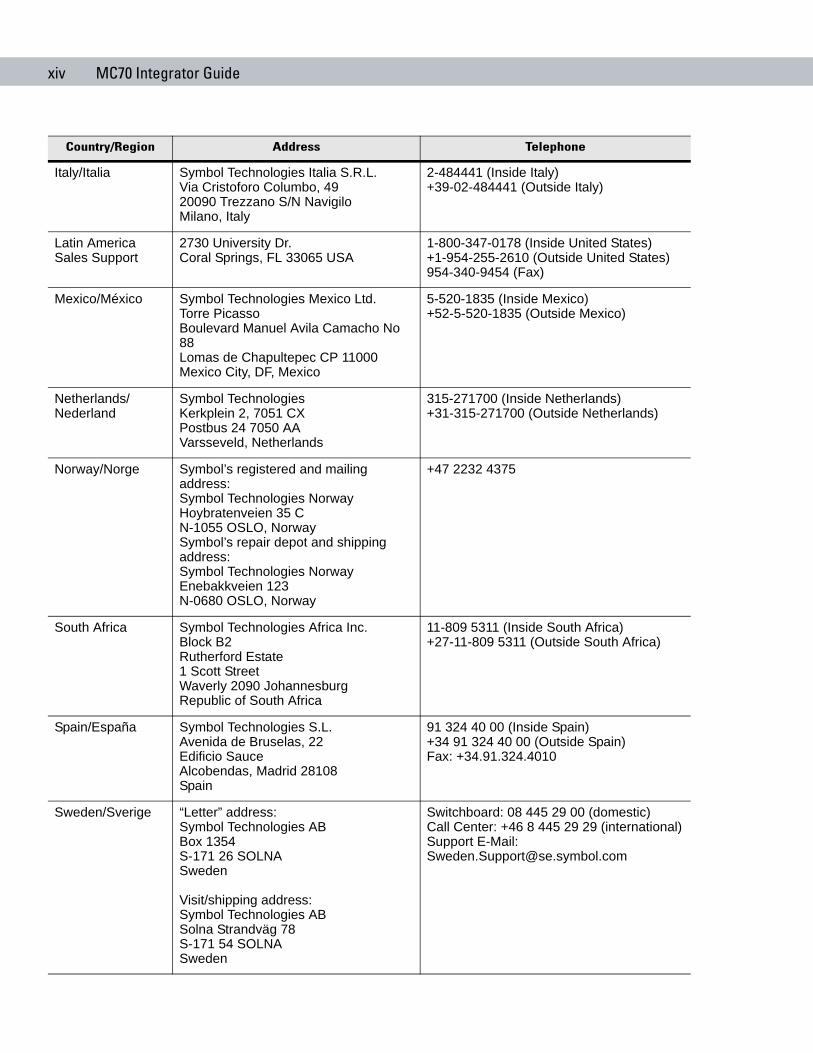
Italy/Italia Symbol Technologies Italia S.R.L.Via Cristoforo Columbo, 4920090 Trezzano S/N NavigiloMilano, Italy
2-484441 (Inside Italy)+39-02-484441 (Outside Italy)
Latin America Sales Support
2730 University Dr.Coral Springs, FL 33065 USA
1-800-347-0178 (Inside United States)+1-954-255-2610 (Outside United States)954-340-9454 (Fax)
Mexico/México Symbol Technologies Mexico Ltd.Torre PicassoBoulevard Manuel Avila Camacho No 88Lomas de Chapultepec CP 11000Mexico City, DF, Mexico
5-520-1835 (Inside Mexico)+52-5-520-1835 (Outside Mexico)
Netherlands/Nederland
Symbol TechnologiesKerkplein 2, 7051 CXPostbus 24 7050 AAVarsseveld, Netherlands
315-271700 (Inside Netherlands)+31-315-271700 (Outside Netherlands)
Norway/Norge Symbol’s registered and mailing address:Symbol Technologies NorwayHoybratenveien 35 CN-1055 OSLO, NorwaySymbol’s repair depot and shipping address:Symbol Technologies NorwayEnebakkveien 123N-0680 OSLO, Norway
+47 2232 4375
South Africa Symbol Technologies Africa Inc.Block B2Rutherford Estate1 Scott StreetWaverly 2090 JohannesburgRepublic of South Africa
11-809 5311 (Inside South Africa)+27-11-809 5311 (Outside South Africa)
Spain/España Symbol Technologies S.L.Avenida de Bruselas, 22Edificio SauceAlcobendas, Madrid 28108Spain
91 324 40 00 (Inside Spain)+34 91 324 40 00 (Outside Spain)Fax: +34.91.324.4010
Sweden/Sverige “Letter” address:Symbol Technologies ABBox 1354S-171 26 SOLNASweden
Visit/shipping address:Symbol Technologies ABSolna Strandväg 78S-171 54 SOLNASweden
Switchboard: 08 445 29 00 (domestic)Call Center: +46 8 445 29 29 (international)Support E-Mail: [email protected]
Country/Region Address Telephone

About This Guide xv
If you purchased your Symbol product from a Symbol Business Partner, contact that Business Partner for service.
For the latest version of this guide go to:http://www.symbol.com/manuals.

xvi MC70 Integrator Guide
Chapter 1 Getting Started
Chapter 1
Chapter 1 Getting StartedIntroductionThis chapter provides information about the EDA, accessories, charging the EDA, and resetting the EDA.
Unpacking the EDACarefully remove all protective material from the EDA and save the shipping container for later storage and shipping. Verify that you received the following equipment:
• MC70 EDA
• Lithium-ion battery
• Battery cover/strap assembly
• Tethered stylus
• Protective overlay, installed on display window
• Regulatory Guide
• Quick Start Guide.
Depending on the configuration ordered, the EDA package can also include:
• Standard or extra capacity battery
• AC adaptor
• Communication/charging cable
• Power supply
• US line cord
• Headset
• Single Slot USB/Serial Cradle.
Inspect the equipment. If any equipment is missing or damaged, contact the Symbol Technologies Support Center immediately. See Service Information on page xii for contact information.
1 - 2 MC70 Integrator Guide
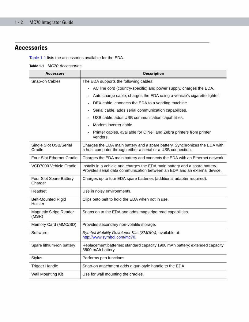
AccessoriesTable 1-1 lists the accessories available for the EDA.
Table 1-1 MC70 Accessories
Accessory Description
Snap-on Cables The EDA supports the following cables:
• AC line cord (country-specific) and power supply, charges the EDA.
• Auto charge cable, charges the EDA using a vehicle’s cigarette lighter.
• DEX cable, connects the EDA to a vending machine.
• Serial cable, adds serial communication capabilities.
• USB cable, adds USB communication capabilities.
• Modem inverter cable.
• Printer cables, available for O’Neil and Zebra printers from printer vendors.
Single Slot USB/Serial Cradle
Charges the EDA main battery and a spare battery. Synchronizes the EDA with a host computer through either a serial or a USB connection.
Four Slot Ethernet Cradle Charges the EDA main battery and connects the EDA with an Ethernet network.
VCD7000 Vehicle Cradle Installs in a vehicle and charges the EDA main battery and a spare battery. Provides serial data communication between an EDA and an external device.
Four Slot Spare Battery Charger
Charges up to four EDA spare batteries (additional adapter required).
Headset Use in noisy environments.
Belt-Mounted Rigid Holster
Clips onto belt to hold the EDA when not in use.
Magnetic Stripe Reader (MSR)
Snaps on to the EDA and adds magstripe read capabilities.
Memory Card (MMC/SD) Provides secondary non-volatile storage.
Software Symbol Mobility Developer Kits (SMDKs), available at:http://www.symbol.com/mc70.
Spare lithium-ion battery Replacement batteries: standard capacity 1900 mAh battery; extended capacity 3800 mAh battery.
Stylus Performs pen functions.
Trigger Handle Snap-on attachment adds a gun-style handle to the EDA.
Wall Mounting Kit Use for wall mounting the cradles.
Getting Started 1 - 3
Getting StartedTo start using the EDA for the first time:
• Install the main battery and cover assembly.
• Charge the EDA.
• Power on the EDA.
• Configure the EDA.
Charge the main battery before or after it is installed. Use one of the spare battery chargers to charge the battery (out of the EDA), or one of the cradles to charge the battery installed in the EDA.
Installing and Removing the Main Battery
Installing the Main Battery
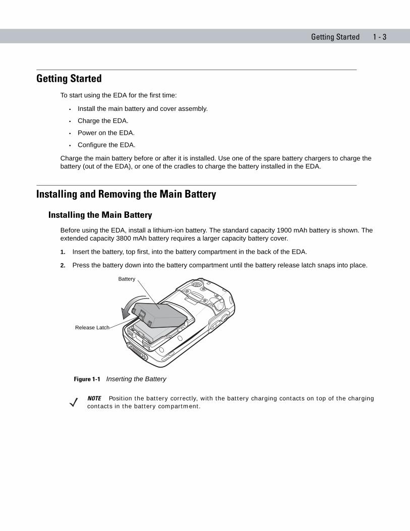
Before using the EDA, install a lithium-ion battery. The standard capacity 1900 mAh battery is shown. The extended capacity 3800 mAh battery requires a larger capacity battery cover.
1. Insert the battery, top first, into the battery compartment in the back of the EDA.
2. Press the battery down into the battery compartment until the battery release latch snaps into place.
Figure 1-1 Inserting the Battery
Battery
Release Latch
NOTE Position the battery correctly, with the battery charging contacts on top of the charging contacts in the battery compartment.
1 - 4 MC70 Integrator Guide
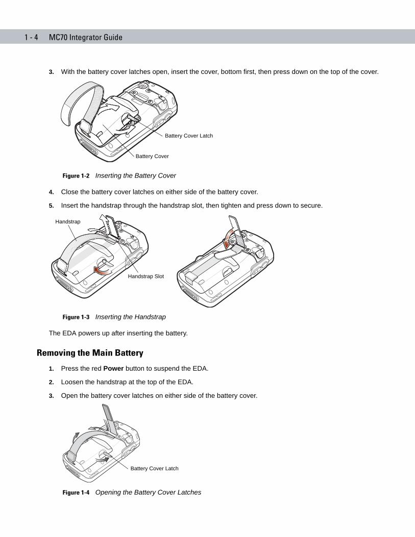
3. With the battery cover latches open, insert the cover, bottom first, then press down on the top of the cover.
Figure 1-2 Inserting the Battery Cover
4. Close the battery cover latches on either side of the battery cover.
5. Insert the handstrap through the handstrap slot, then tighten and press down to secure.
Figure 1-3 Inserting the Handstrap
The EDA powers up after inserting the battery.
Removing the Main Battery
1. Press the red Power button to suspend the EDA.
2. Loosen the handstrap at the top of the EDA.
3. Open the battery cover latches on either side of the battery cover.
Figure 1-4 Opening the Battery Cover Latches
Battery Cover
Battery Cover Latch
Handstrap Slot
Handstrap
Battery Cover Latch
Getting Started 1 - 5
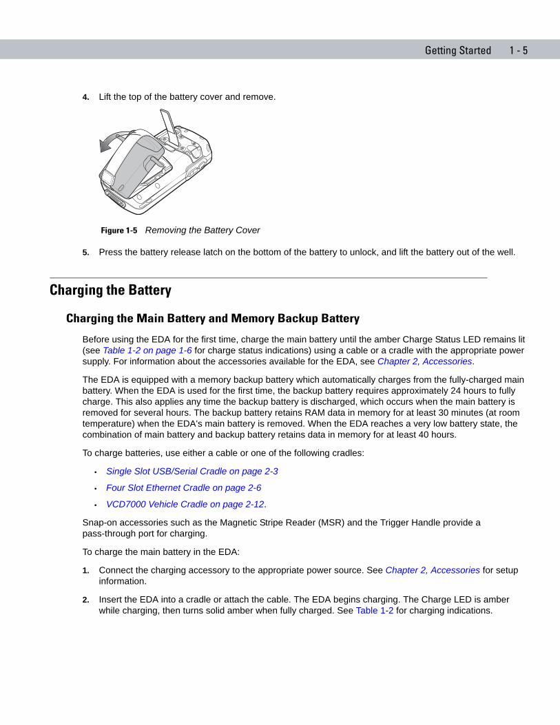
4. Lift the top of the battery cover and remove.
Figure 1-5 Removing the Battery Cover
5. Press the battery release latch on the bottom of the battery to unlock, and lift the battery out of the well.
Charging the Battery
Charging the Main Battery and Memory Backup Battery
Before using the EDA for the first time, charge the main battery until the amber Charge Status LED remains lit (see Table 1-2 on page 1-6 for charge status indications) using a cable or a cradle with the appropriate power supply. For information about the accessories available for the EDA, see Chapter 2, Accessories.
The EDA is equipped with a memory backup battery which automatically charges from the fully-charged main battery. When the EDA is used for the first time, the backup battery requires approximately 24 hours to fully charge. This also applies any time the backup battery is discharged, which occurs when the main battery is removed for several hours. The backup battery retains RAM data in memory for at least 30 minutes (at room temperature) when the EDA's main battery is removed. When the EDA reaches a very low battery state, the combination of main battery and backup battery retains data in memory for at least 40 hours.
To charge batteries, use either a cable or one of the following cradles:
• Single Slot USB/Serial Cradle on page 2-3
• Four Slot Ethernet Cradle on page 2-6
• VCD7000 Vehicle Cradle on page 2-12.
Snap-on accessories such as the Magnetic Stripe Reader (MSR) and the Trigger Handle provide a pass-through port for charging.
To charge the main battery in the EDA:
1. Connect the charging accessory to the appropriate power source. See Chapter 2, Accessories for setup information.
2. Insert the EDA into a cradle or attach the cable. The EDA begins charging. The Charge LED is amber while charging, then turns solid amber when fully charged. See Table 1-2 for charging indications.
1 - 6 MC70 Integrator Guide
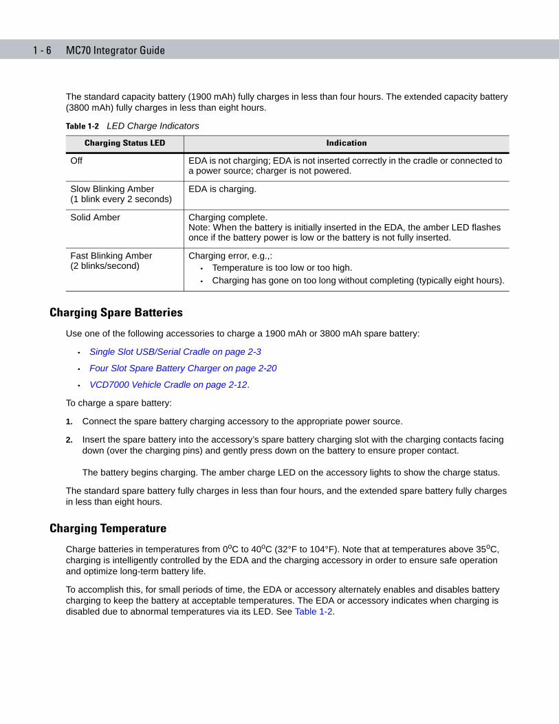
The standard capacity battery (1900 mAh) fully charges in less than four hours. The extended capacity battery (3800 mAh) fully charges in less than eight hours.
Charging Spare Batteries
Use one of the following accessories to charge a 1900 mAh or 3800 mAh spare battery:
• Single Slot USB/Serial Cradle on page 2-3
• Four Slot Spare Battery Charger on page 2-20
• VCD7000 Vehicle Cradle on page 2-12.
To charge a spare battery:
1. Connect the spare battery charging accessory to the appropriate power source.
2. Insert the spare battery into the accessory’s spare battery charging slot with the charging contacts facing down (over the charging pins) and gently press down on the battery to ensure proper contact.
The battery begins charging. The amber charge LED on the accessory lights to show the charge status.
The standard spare battery fully charges in less than four hours, and the extended spare battery fully charges in less than eight hours.
Charging Temperature
Charge batteries in temperatures from 0oC to 40oC (32°F to 104°F). Note that at temperatures above 35oC, charging is intelligently controlled by the EDA and the charging accessory in order to ensure safe operation and optimize long-term battery life.
To accomplish this, for small periods of time, the EDA or accessory alternately enables and disables battery charging to keep the battery at acceptable temperatures. The EDA or accessory indicates when charging is disabled due to abnormal temperatures via its LED. See Table 1-2.
Table 1-2 LED Charge Indicators
Charging Status LED Indication
Off EDA is not charging; EDA is not inserted correctly in the cradle or connected to a power source; charger is not powered.
Slow Blinking Amber (1 blink every 2 seconds)
EDA is charging.
Solid Amber Charging complete.Note: When the battery is initially inserted in the EDA, the amber LED flashes once if the battery power is low or the battery is not fully inserted.
Fast Blinking Amber (2 blinks/second)
Charging error, e.g.,:• Temperature is too low or too high.• Charging has gone on too long without completing (typically eight hours).
Getting Started 1 - 7
Powering On the EDAPress the Power button to turn on the EDA. If the EDA does not power on, reset it. See Resetting the EDA on page 1-7.
When turning the EDA on for the first time, the Symbol splash screen displays for about a minute as the EDA initializes its flash file system, then the calibration window appears. Note that these windows also appear upon cold boot.
Calibrating the Screen
To calibrate the screen so the cursor on the touch screen aligns with the tip of the stylus:
1. Remove the stylus from its holder on the back of the EDA.
2. Carefully press and briefly hold the tip of stylus on the center of each target that appears on the screen.
3. Repeat as the target moves around the screen, then tap the screen to continue.
Resetting the EDAThere are two reset functions, warm boot and cold boot. A warm boot restarts the EDA by closing all running programs. A cold boot also restarts the EDA, and also resets the clock. Data saved in flash memory or a memory card is not lost.
Perform a warm boot first. If the EDA still does not respond, perform a cold boot.
Performing a Warm Boot
Hold down the Power button for approximately five seconds. As soon as the EDA starts to perform a warm boot release the Power button.
Performing a Cold Boot
To perform a cold boot:
1. Simultaneously press the Power button and the 1 and 9 keys.
2. After the EDA initializes, calibrate the screen. See Calibrating the Screen on page 1-7 to adjust the EDA screen.
NOTE When the EDA powers up after inserting a battery for the first time, the device boots and powers on automatically.
1 - 8 MC70 Integrator Guide
Waking the EDAThe wakeup conditions define what actions wake up the EDA. These settings are configurable and the factory default settings shown in Table 1-3 are subject to change/update.
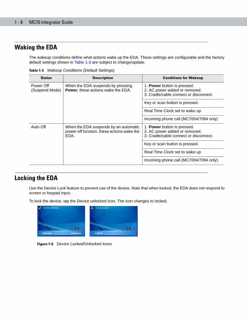
Locking the EDAUse the Device Lock feature to prevent use of the device. Note that when locked, the EDA does not respond to screen or keypad input.
To lock the device, tap the Device unlocked icon. The icon changes to locked.
Figure 1-6 Device Locked/Unlocked Icons
Table 1-3 Wakeup Conditions (Default Settings)
Status Description Conditions for Wakeup
Power Off (Suspend Mode)
When the EDA suspends by pressing Power, these actions wake the EDA.
1. Power button is pressed.2. AC power added or removed.3. Cradle/cable connect or disconnect.
Key or scan button is pressed.
Real Time Clock set to wake up.
Incoming phone call (MC7004/7094 only)
Auto Off When the EDA suspends by an automatic power-off function, these actions wake the EDA.
1. Power button is pressed.2. AC power added or removed.3. Cradle/cable connect or disconnect.
Key or scan button is pressed.
Real Time Clock set to wake up.
Incoming phone call (MC7004/7094 only)
Getting Started 1 - 9
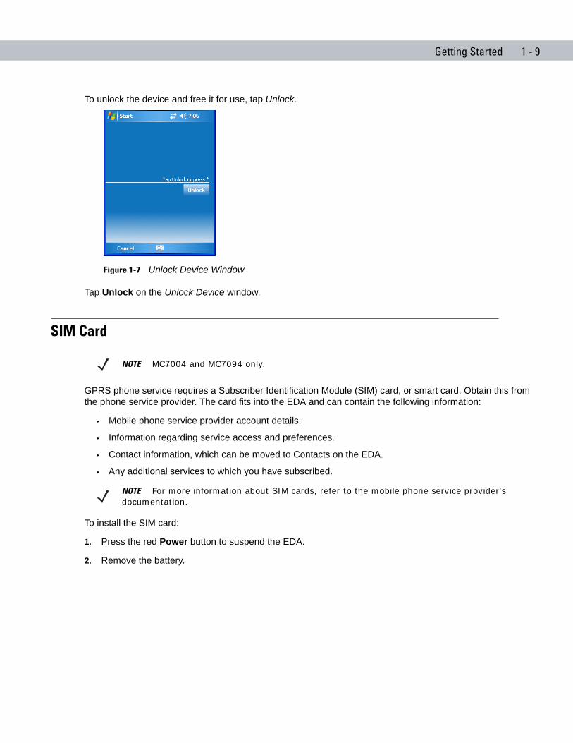
To unlock the device and free it for use, tap Unlock.
Figure 1-7 Unlock Device Window
Tap Unlock on the Unlock Device window.
SIM Card
GPRS phone service requires a Subscriber Identification Module (SIM) card, or smart card. Obtain this from the phone service provider. The card fits into the EDA and can contain the following information:
• Mobile phone service provider account details.
• Information regarding service access and preferences.
• Contact information, which can be moved to Contacts on the EDA.
• Any additional services to which you have subscribed.
To install the SIM card:
1. Press the red Power button to suspend the EDA.
2. Remove the battery.
NOTE MC7004 and MC7094 only.
NOTE For more information about SIM cards, refer to the mobile phone service provider's documentation.
1 - 10 MC70 Integrator Guide
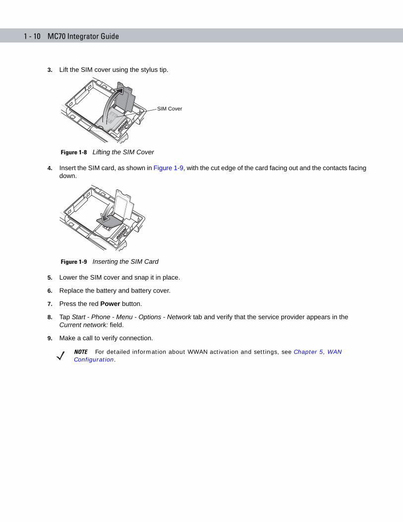
3. Lift the SIM cover using the stylus tip.
Figure 1-8 Lifting the SIM Cover
4. Insert the SIM card, as shown in Figure 1-9, with the cut edge of the card facing out and the contacts facing down.
Figure 1-9 Inserting the SIM Card
5. Lower the SIM cover and snap it in place.
6. Replace the battery and battery cover.
7. Press the red Power button.
8. Tap Start - Phone - Menu - Options - Network tab and verify that the service provider appears in the Current network: field.
9. Make a call to verify connection.
SIM Cover
NOTE For detailed information about WWAN activation and settings, see Chapter 5, WAN Configuration.

Getting Started 1 - 11
Removing the Screen ProtectorA screen protector is applied to the EDA. Symbol recommends using this to minimize wear and tear. Screen protectors enhance the usability and durability of touch screen displays.
To remove the screen protector, lift the corner using a thin plastic card, such as a credit card, then carefully lift it off the display.
Figure 1-10 Removing the Screen Protector
Lift ScreenProtector Corner
CAUTION Do not use a sharp object to remove the protector. Doing so can damage the display.!
NOTE Not using a screen protector can affect warranty coverage. To purchase replacement protectors, contact your local account manager or Symbol Technologies, Inc. These include screen protector installation instructions. Part number: KT-67525-01 Screen Protector 3/pk.

1 - 12 MC70 Integrator Guide
Chapter 2 Accessories
Chapter 2
Chapter 2 AccessoriesIntroductionMC70 accessories provide a variety of product support capabilities. Accessories include cables, cradles, four-slot spare battery charger, headset, Multimedia Card (MMC), Secure Device (SD) card, Magnetic Stripe Reader (MSR), and trigger handle.
Cables
Snap one of the following cables on to the EDA to connect an external device.
• USB Client charge cable
• RS232 charge cable
• DEX cable
• Modem inverter cable
• Autocharge cable.
Cradles
• Single Slot USB/Serial cradle charges the EDA main battery and a spare battery. It also synchronizes the EDA with a host computer through a USB connection.
• Four Slot Ethernet cradle charges the EDA main battery and connects the EDA with an Ethernet network.
• Vehicle cradle charges the EDA main battery and a spare battery.
Miscellaneous
• Four Slot Spare Battery Charger charges up to four EDA spare batteries.
• Headset can be used in noisy environments.
• Multimedia Card or Secure Digital (SD) Card provides secondary non-volatile storage.
• Belt Mounted Rigid Holster holds the EDA when not in use.
2 - 2 MC70 Integrator Guide
Snap-on Modules
• MSR snaps on to the EDA and adds magstripe read capabilities.
• TRG7000 Trigger Handle adds a gun-style handle with a scanning trigger to the EDA.
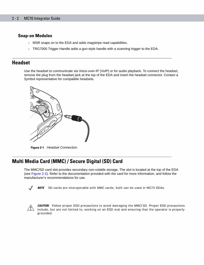
HeadsetUse the headset to communicate via Voice-over-IP (VoIP) or for audio playback. To connect the headset, remove the plug from the headset jack at the top of the EDA and insert the headset connector. Contact a Symbol representative for compatible headsets.
Figure 2-1 Headset Connection
Multi Media Card (MMC) / Secure Digital (SD) CardThe MMC/SD card slot provides secondary non-volatile storage. The slot is located at the top of the EDA (see Figure 2-2). Refer to the documentation provided with the card for more information, and follow the manufacturer’s recommendations for use.
NOTE SD cards are interoperable with MMC cards; both can be used in MC70 EDAs.
CAUTION Follow proper ESD precautions to avoid damaging the MMC/SD. Proper ESD precautions include, but are not limited to, working on an ESD mat and ensuring that the operator is properly grounded.
!
Accessories 2 - 3
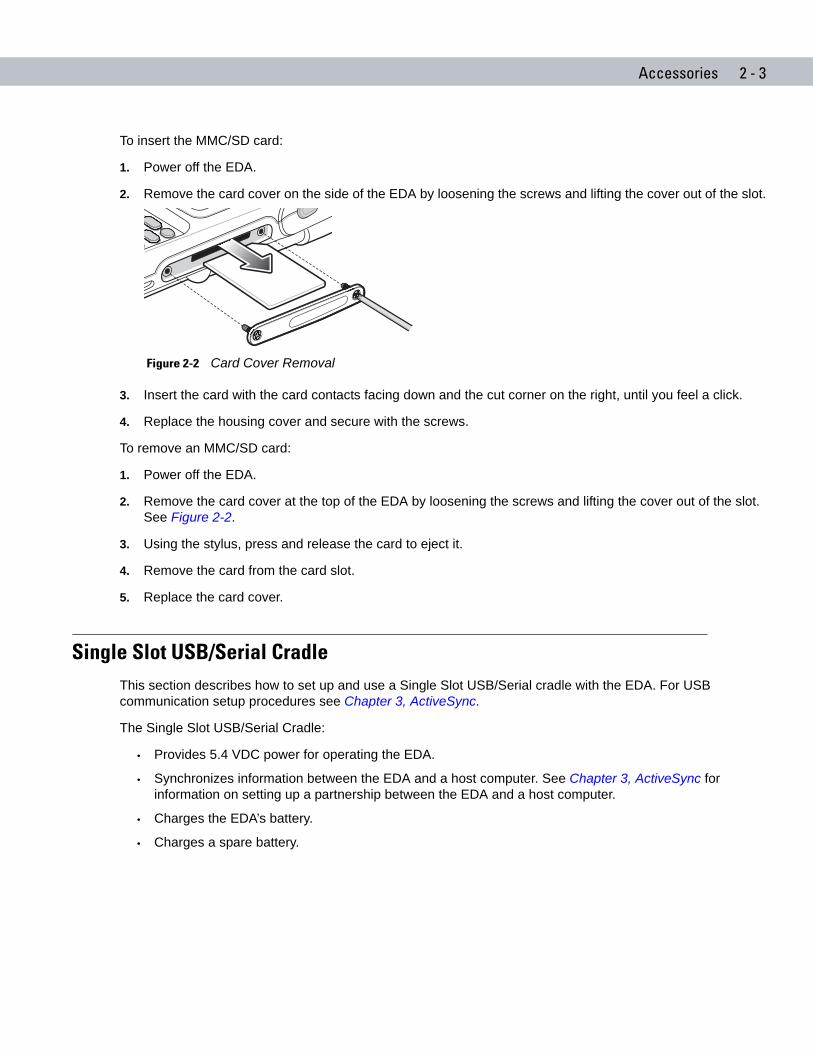
To insert the MMC/SD card:
1. Power off the EDA.
2. Remove the card cover on the side of the EDA by loosening the screws and lifting the cover out of the slot.
Figure 2-2 Card Cover Removal
3. Insert the card with the card contacts facing down and the cut corner on the right, until you feel a click.
4. Replace the housing cover and secure with the screws.
To remove an MMC/SD card:
1. Power off the EDA.
2. Remove the card cover at the top of the EDA by loosening the screws and lifting the cover out of the slot. See Figure 2-2.
3. Using the stylus, press and release the card to eject it.
4. Remove the card from the card slot.
5. Replace the card cover.
Single Slot USB/Serial CradleThis section describes how to set up and use a Single Slot USB/Serial cradle with the EDA. For USB communication setup procedures see Chapter 3, ActiveSync.
The Single Slot USB/Serial Cradle:
• Provides 5.4 VDC power for operating the EDA.
• Synchronizes information between the EDA and a host computer. See Chapter 3, ActiveSync for information on setting up a partnership between the EDA and a host computer.
• Charges the EDA’s battery.
• Charges a spare battery.
2 - 4 MC70 Integrator Guide
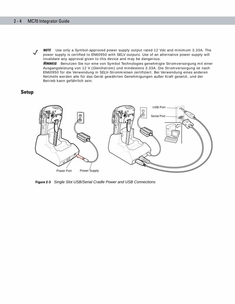
Setup
Figure 2-3 Single Slot USB/Serial Cradle Power and USB Connections
NOTE Use only a Symbol-approved power supply output rated 12 Vdc and minimum 3.33A. The power supply is certified to EN60950 with SELV outputs. Use of an alternative power supply will invalidate any approval given to this device and may be dangerous.HINWEIS Benutzen Sie nur eine von Symbol Technologies genehmigte Stromversorgung mit einer Ausgangsleistung von 12 V (Gleichstrom) und mindestens 3.33A. Die Stromversorgung ist nach EN60950 für die Verwendung in SELV-Stromkreisen zertifiziert. Bei Verwendung eines anderen Netzteils werden alle für das Gerät gewährten Genehmigungen außer Kraft gesetzt, und der Betrieb kann gefährlich sein.
Power Supply
USB Port
Power Port
Serial Port
Accessories 2 - 5
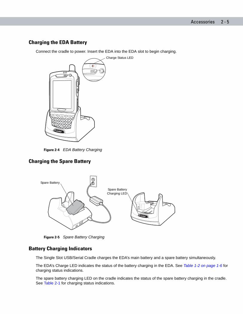
Charging the EDA Battery
Connect the cradle to power. Insert the EDA into the EDA slot to begin charging.
Figure 2-4 EDA Battery Charging
Charging the Spare Battery
Figure 2-5 Spare Battery Charging
Battery Charging Indicators
The Single Slot USB/Serial Cradle charges the EDA’s main battery and a spare battery simultaneously.
The EDA’s Charge LED indicates the status of the battery charging in the EDA. See Table 1-2 on page 1-6 for charging status indications.
The spare battery charging LED on the cradle indicates the status of the spare battery charging in the cradle. See Table 2-1 for charging status indications.
Charge Status LED
Spare Battery
Spare BatteryCharging LED
2 - 6 MC70 Integrator Guide
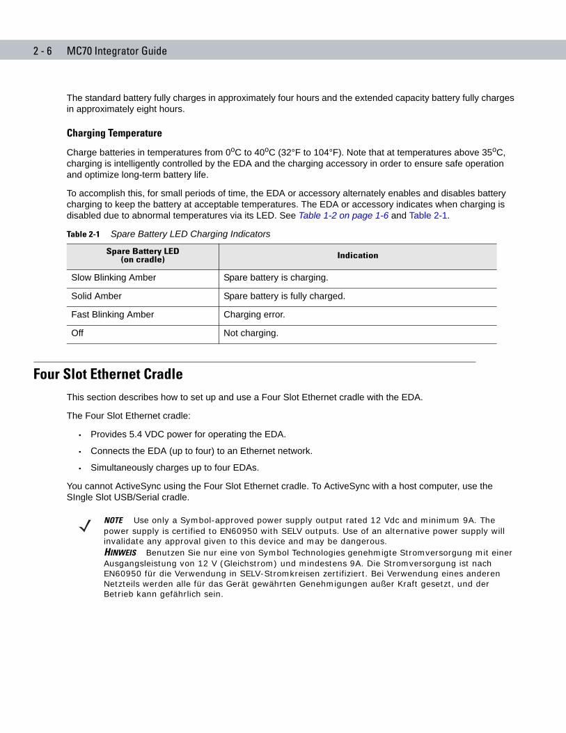
The standard battery fully charges in approximately four hours and the extended capacity battery fully charges in approximately eight hours.
Charging Temperature
Charge batteries in temperatures from 0oC to 40oC (32°F to 104°F). Note that at temperatures above 35oC, charging is intelligently controlled by the EDA and the charging accessory in order to ensure safe operation and optimize long-term battery life.
To accomplish this, for small periods of time, the EDA or accessory alternately enables and disables battery charging to keep the battery at acceptable temperatures. The EDA or accessory indicates when charging is disabled due to abnormal temperatures via its LED. See Table 1-2 on page 1-6 and Table 2-1.
Four Slot Ethernet CradleThis section describes how to set up and use a Four Slot Ethernet cradle with the EDA.
The Four Slot Ethernet cradle:
• Provides 5.4 VDC power for operating the EDA.
• Connects the EDA (up to four) to an Ethernet network.
• Simultaneously charges up to four EDAs.
You cannot ActiveSync using the Four Slot Ethernet cradle. To ActiveSync with a host computer, use the SIngle Slot USB/Serial cradle.
Table 2-1 Spare Battery LED Charging Indicators
Spare Battery LED(on cradle) Indication
Slow Blinking Amber Spare battery is charging.
Solid Amber Spare battery is fully charged.
Fast Blinking Amber Charging error.
Off Not charging.
NOTE Use only a Symbol-approved power supply output rated 12 Vdc and minimum 9A. The power supply is certified to EN60950 with SELV outputs. Use of an alternative power supply will invalidate any approval given to this device and may be dangerous.HINWEIS Benutzen Sie nur eine von Symbol Technologies genehmigte Stromversorgung mit einer Ausgangsleistung von 12 V (Gleichstrom) und mindestens 9A. Die Stromversorgung ist nach EN60950 für die Verwendung in SELV-Stromkreisen zertifiziert. Bei Verwendung eines anderen Netzteils werden alle für das Gerät gewährten Genehmigungen außer Kraft gesetzt, und der Betrieb kann gefährlich sein.
Accessories 2 - 7
Setup
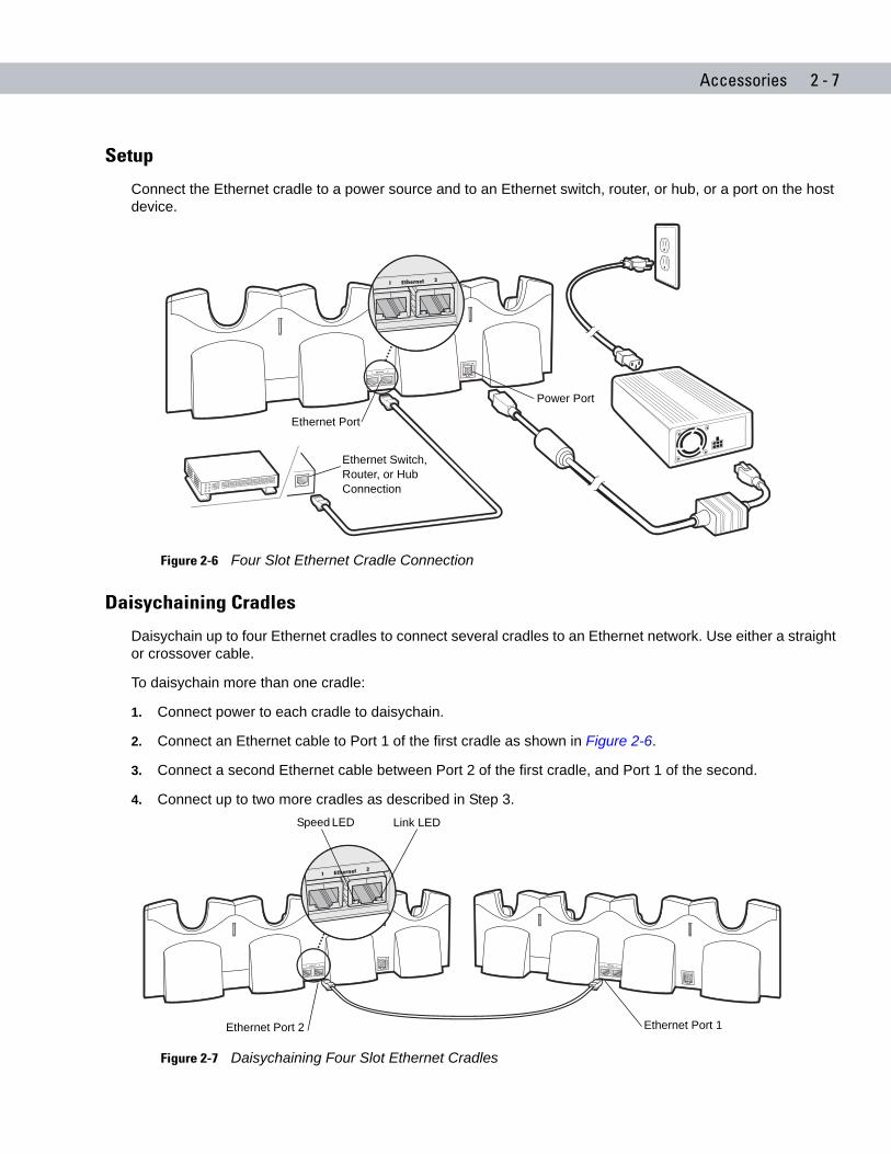
Connect the Ethernet cradle to a power source and to an Ethernet switch, router, or hub, or a port on the host device.
Figure 2-6 Four Slot Ethernet Cradle Connection
Daisychaining Cradles
Daisychain up to four Ethernet cradles to connect several cradles to an Ethernet network. Use either a straight or crossover cable.
To daisychain more than one cradle:
1. Connect power to each cradle to daisychain.
2. Connect an Ethernet cable to Port 1 of the first cradle as shown in Figure 2-6.
3. Connect a second Ethernet cable between Port 2 of the first cradle, and Port 1 of the second.
4. Connect up to two more cradles as described in Step 3.
Figure 2-7 Daisychaining Four Slot Ethernet Cradles
Power Port
Ethernet Port
Ethernet Switch, Router, or Hub Connection
Ethernet Port 1Ethernet Port 2
Link LEDSpeed LED
2 - 8 MC70 Integrator Guide
Bandwidth Considerations when Daisychaining
Each cradle added to the daisychain impacts the bandwidth provided to the inserted EDAs, particularly when the EDAs attempt to send and receive at data rates that exceed the bandwidth provided to the chain (typically 100 Mbps). If an EDA in a daisychained cradle does not use its bandwidth, that bandwidth is allocated to other inserted EDAs.
Table 2-2 shows available bandwidth, based on 100 Mpbs, for the maximum number of daisychained cradles, with each attempting transmission at the maximum data rate.
Ethernet Cradle Drivers
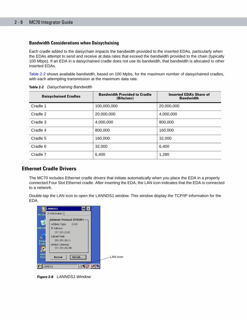
The MC70 includes Ethernet cradle drivers that initiate automatically when you place the EDA in a properly connected Four Slot Ethernet cradle. After inserting the EDA, the LAN icon indicates that the EDA is connected to a network.
Double-tap the LAN icon to open the LANNDS1 window. This window display the TCP/IP information for the EDA.
Figure 2-8 LANNDS1 Window
Table 2-2 Daisychaining Bandwidth
Daisychained Cradles Bandwidth Provided to Cradle (Bits/sec)
Inserted EDA’s Share of Bandwidth
Cradle 1 100,000,000 20,000,000
Cradle 2 20,000,000 4,000,000
Cradle 3 4,000,000 800,000
Cradle 4 800,000 160,000
Cradle 5 160,000 32,000
Cradle 6 32,000 6,400
Cradle 7 6,400 1,280
LAN Icon
Accessories 2 - 9
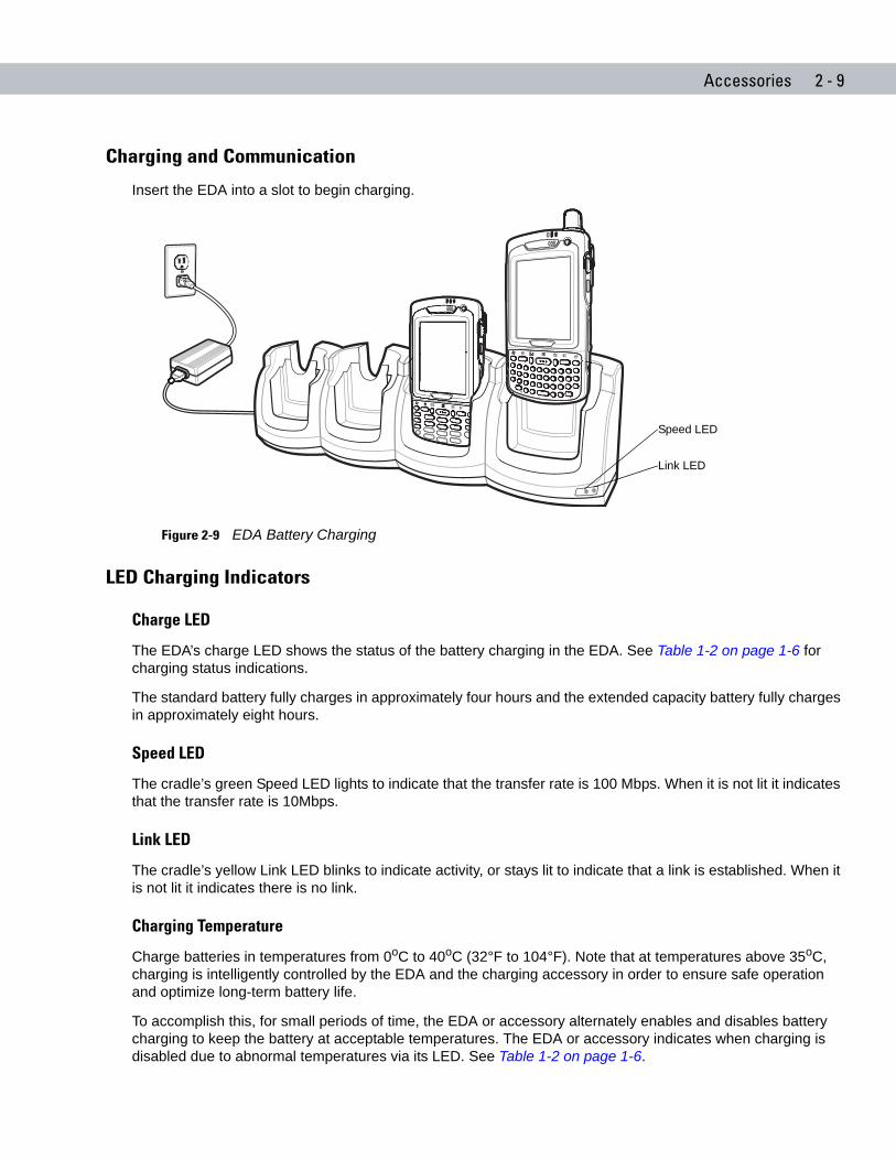
Charging and Communication
Insert the EDA into a slot to begin charging.
Figure 2-9 EDA Battery Charging
LED Charging Indicators
Charge LED
The EDA’s charge LED shows the status of the battery charging in the EDA. See Table 1-2 on page 1-6 for charging status indications.
The standard battery fully charges in approximately four hours and the extended capacity battery fully charges in approximately eight hours.
Speed LED
The cradle’s green Speed LED lights to indicate that the transfer rate is 100 Mbps. When it is not lit it indicates that the transfer rate is 10Mbps.
Link LED
The cradle’s yellow Link LED blinks to indicate activity, or stays lit to indicate that a link is established. When it is not lit it indicates there is no link.
Charging Temperature
Charge batteries in temperatures from 0oC to 40oC (32°F to 104°F). Note that at temperatures above 35oC, charging is intelligently controlled by the EDA and the charging accessory in order to ensure safe operation and optimize long-term battery life.
To accomplish this, for small periods of time, the EDA or accessory alternately enables and disables battery charging to keep the battery at acceptable temperatures. The EDA or accessory indicates when charging is disabled due to abnormal temperatures via its LED. See Table 1-2 on page 1-6.
Link LED
Speed LED
2 - 10 MC70 Integrator Guide
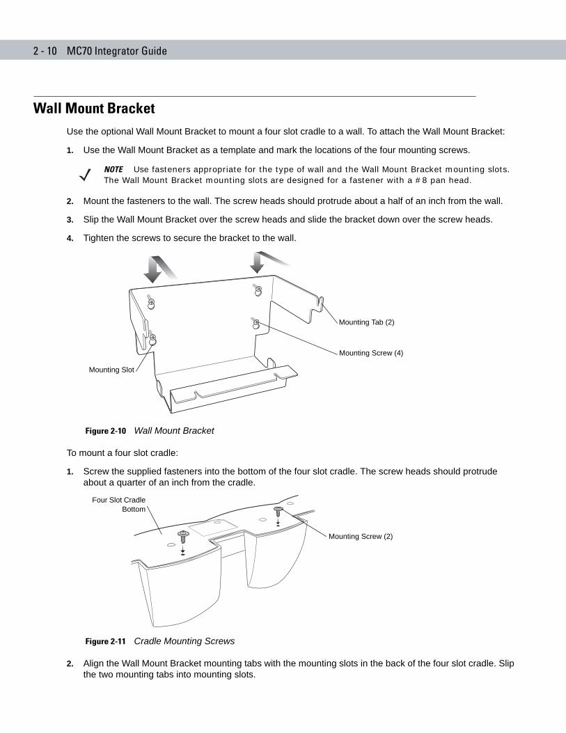
Wall Mount BracketUse the optional Wall Mount Bracket to mount a four slot cradle to a wall. To attach the Wall Mount Bracket:
1. Use the Wall Mount Bracket as a template and mark the locations of the four mounting screws.
2. Mount the fasteners to the wall. The screw heads should protrude about a half of an inch from the wall.
3. Slip the Wall Mount Bracket over the screw heads and slide the bracket down over the screw heads.
4. Tighten the screws to secure the bracket to the wall.
Figure 2-10 Wall Mount Bracket
To mount a four slot cradle:
1. Screw the supplied fasteners into the bottom of the four slot cradle. The screw heads should protrude about a quarter of an inch from the cradle.
Figure 2-11 Cradle Mounting Screws
2. Align the Wall Mount Bracket mounting tabs with the mounting slots in the back of the four slot cradle. Slip the two mounting tabs into mounting slots.
NOTE Use fasteners appropriate for the type of wall and the Wall Mount Bracket mounting slots. The Wall Mount Bracket mounting slots are designed for a fastener with a #8 pan head.
Mounting Screw (4)
Mounting Tab (2)
Mounting Slot
Mounting Screw (2)
Four Slot CradleBottom
Accessories 2 - 11
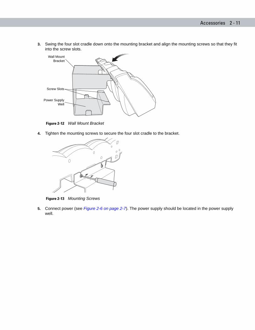
3. Swing the four slot cradle down onto the mounting bracket and align the mounting screws so that they fit into the screw slots.
Figure 2-12 Wall Mount Bracket
4. Tighten the mounting screws to secure the four slot cradle to the bracket.
Figure 2-13 Mounting Screws
5. Connect power (see Figure 2-6 on page 2-7). The power supply should be located in the power supply well.
Wall MountBracket
Screw Slots
Power SupplyWell
2 - 12 MC70 Integrator Guide
VCD7000 Vehicle CradleThis section describes how to use a VCD7000 vehicle cradle with the EDA. For cradle installation and communication setup procedures refer to the MC70 Integrator Guide.
Once installed in a vehicle, the cradle:
• holds the EDA securely in place
• provides power for operating the EDA
• provides a serial port for data communication between an EDA and an external device (e.g., a printer)
• re-charges the battery in the EDA
• re-charges a standard capacity or extended capacity spare battery.
Requirements
For mounting:
• four #8-32 self-locking nuts
• four #8 washers
• a drill with a #6 drill bit (.204”).
For power connection:
• power input cable (included), p/n 25-61987-01
• UL Listed in-line fuse rated 250V, 5A (included), must be used if not connecting to vehicle’s fuse panel
• in-line fuse holder (included), must be used if not connecting to vehicle’s fuse panel.
For serial connection:
• DB9 female serial cable (some devices may require null modem).
For communication:
• an MC70
• host computer setup and EDA setup (as determined by the application you are using).
Connector Ports
There are two connection ports on the bottom of the vehicle cradle:
Table 2-3 Vehicle Cradle Connection Ports
Ports Function
Serial Standard RS 232 port used for direct connection to the serial device using a serial cable.
Power Used for connecting to vehicle power using the power input cable.
Accessories 2 - 13
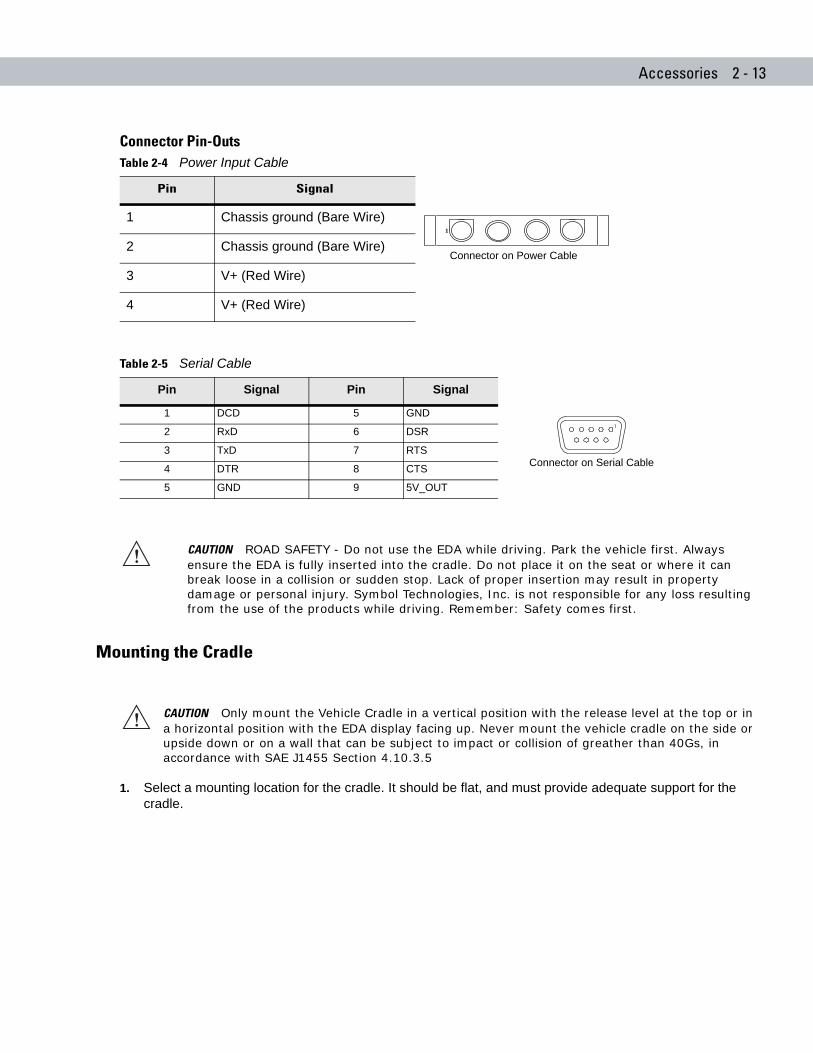
Connector Pin-Outs
Mounting the Cradle
1. Select a mounting location for the cradle. It should be flat, and must provide adequate support for the cradle.
Table 2-4 Power Input Cable
Pin Signal
1 Chassis ground (Bare Wire)
2 Chassis ground (Bare Wire)
3 V+ (Red Wire)
4 V+ (Red Wire)
Table 2-5 Serial Cable
Pin Signal Pin Signal
1 DCD 5 GND
2 RxD 6 DSR
3 TxD 7 RTS
4 DTR 8 CTS
5 GND 9 5V_OUT
CAUTION ROAD SAFETY - Do not use the EDA while driving. Park the vehicle first. Always ensure the EDA is fully inserted into the cradle. Do not place it on the seat or where it can break loose in a collision or sudden stop. Lack of proper insertion may result in property damage or personal injury. Symbol Technologies, Inc. is not responsible for any loss resulting from the use of the products while driving. Remember: Safety comes first.
1
Connector on Power Cable
Connector on Serial Cable
CAUTION Only mount the Vehicle Cradle in a vertical position with the release level at the top or in a horizontal position with the EDA display facing up. Never mount the vehicle cradle on the side or upside down or on a wall that can be subject to impact or collision of greather than 40Gs, in accordance with SAE J1455 Section 4.10.3.5
2 - 14 MC70 Integrator Guide
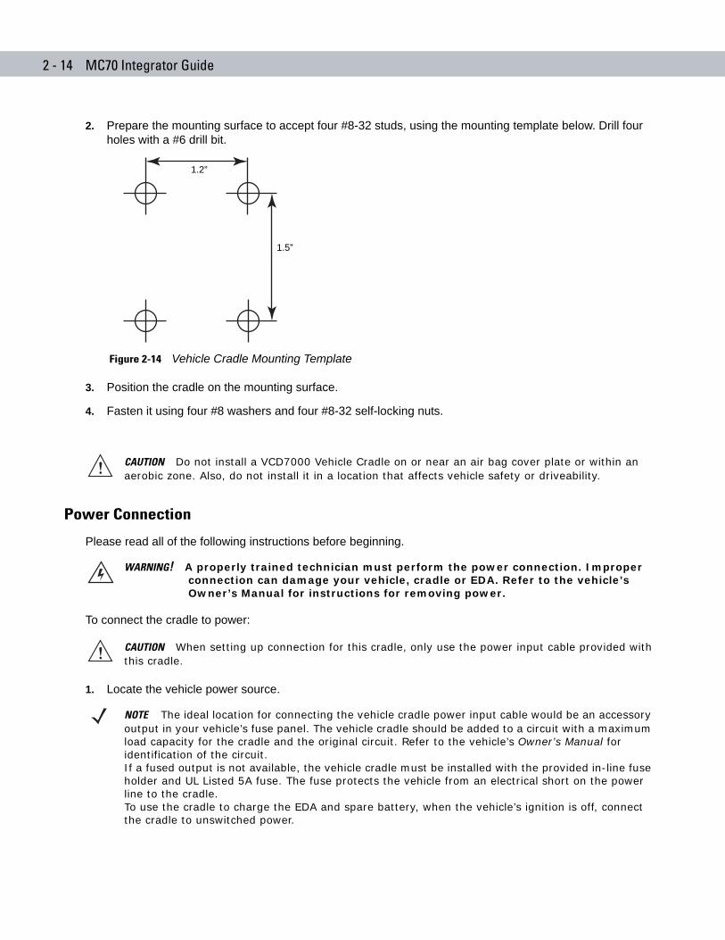
2. Prepare the mounting surface to accept four #8-32 studs, using the mounting template below. Drill four holes with a #6 drill bit.
Figure 2-14 Vehicle Cradle Mounting Template
3. Position the cradle on the mounting surface.
4. Fasten it using four #8 washers and four #8-32 self-locking nuts.
Power Connection
Please read all of the following instructions before beginning.
To connect the cradle to power:
1. Locate the vehicle power source.
CAUTION Do not install a VCD7000 Vehicle Cradle on or near an air bag cover plate or within an aerobic zone. Also, do not install it in a location that affects vehicle safety or driveability.
1.5”
1.2”
WARNING! A properly trained technician must perform the power connection. Improper connection can damage your vehicle, cradle or EDA. Refer to the vehicle’s Owner’s Manual for instructions for removing power.
CAUTION When setting up connection for this cradle, only use the power input cable provided with this cradle.
NOTE The ideal location for connecting the vehicle cradle power input cable would be an accessory output in your vehicle’s fuse panel. The vehicle cradle should be added to a circuit with a maximum load capacity for the cradle and the original circuit. Refer to the vehicle’s Owner’s Manual for identification of the circuit. If a fused output is not available, the vehicle cradle must be installed with the provided in-line fuse holder and UL Listed 5A fuse. The fuse protects the vehicle from an electrical short on the power line to the cradle. To use the cradle to charge the EDA and spare battery, when the vehicle’s ignition is off, connect the cradle to unswitched power.
Accessories 2 - 15
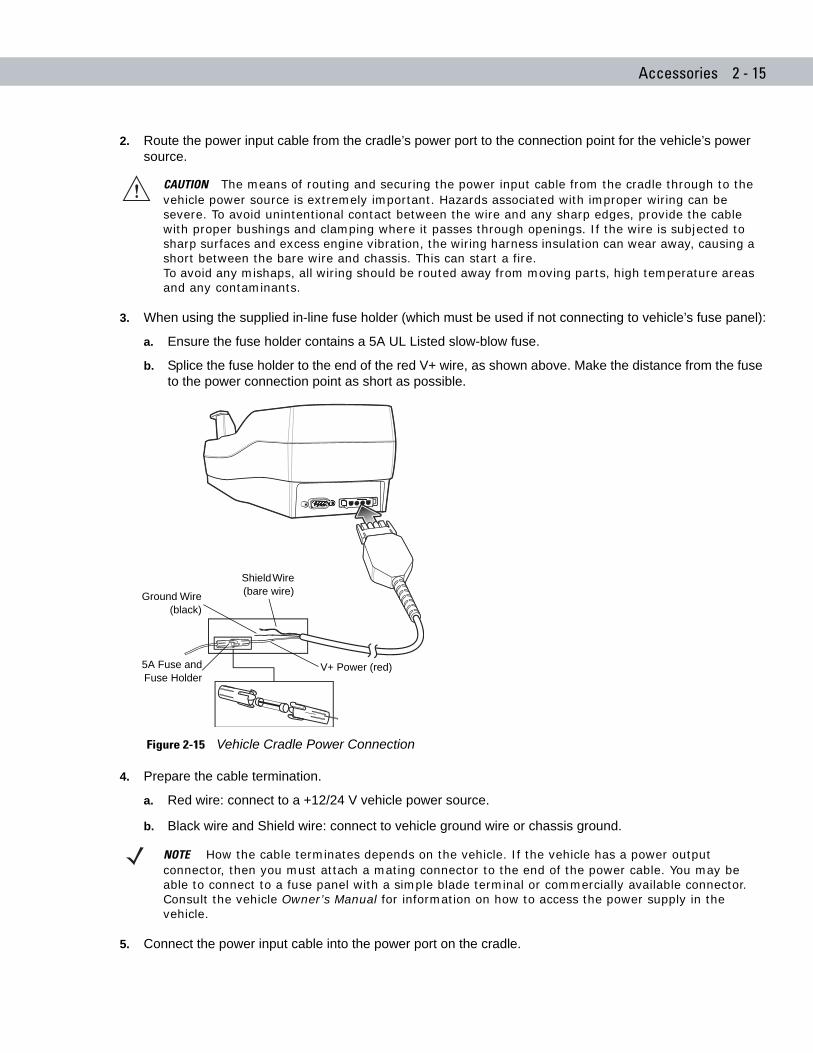
2. Route the power input cable from the cradle’s power port to the connection point for the vehicle’s power source.
3. When using the supplied in-line fuse holder (which must be used if not connecting to vehicle’s fuse panel):
a. Ensure the fuse holder contains a 5A UL Listed slow-blow fuse.
b. Splice the fuse holder to the end of the red V+ wire, as shown above. Make the distance from the fuse to the power connection point as short as possible.
Figure 2-15 Vehicle Cradle Power Connection
4. Prepare the cable termination.
a. Red wire: connect to a +12/24 V vehicle power source.
b. Black wire and Shield wire: connect to vehicle ground wire or chassis ground.
5. Connect the power input cable into the power port on the cradle.
CAUTION The means of routing and securing the power input cable from the cradle through to the vehicle power source is extremely important. Hazards associated with improper wiring can be severe. To avoid unintentional contact between the wire and any sharp edges, provide the cable with proper bushings and clamping where it passes through openings. If the wire is subjected to sharp surfaces and excess engine vibration, the wiring harness insulation can wear away, causing a short between the bare wire and chassis. This can start a fire.To avoid any mishaps, all wiring should be routed away from moving parts, high temperature areas and any contaminants.
NOTE How the cable terminates depends on the vehicle. If the vehicle has a power output connector, then you must attach a mating connector to the end of the power cable. You may be able to connect to a fuse panel with a simple blade terminal or commercially available connector. Consult the vehicle Owner’s Manual for information on how to access the power supply in the vehicle.
Shield Wire (bare wire)Ground Wire
(black)
V+ Power (red)5A Fuse andFuse Holder
2 - 16 MC70 Integrator Guide
To see if the cradle has power, insert the EDA. The Charging LED on the EDA blinks slowly to indicate charging and turns solid amber when the battery is completely charged. See Table 1-2 on page 1-6 for other indications.
Serial Device Connection
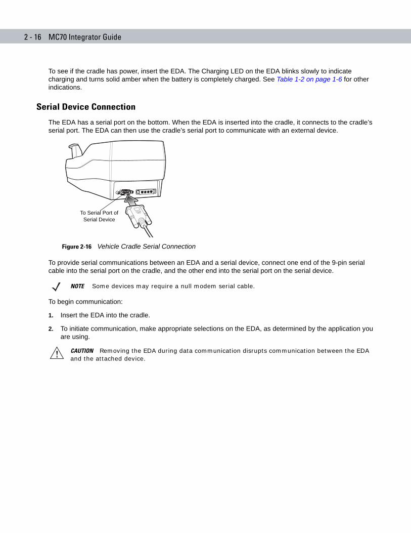
The EDA has a serial port on the bottom. When the EDA is inserted into the cradle, it connects to the cradle’s serial port. The EDA can then use the cradle’s serial port to communicate with an external device.
Figure 2-16 Vehicle Cradle Serial Connection
To provide serial communications between an EDA and a serial device, connect one end of the 9-pin serial cable into the serial port on the cradle, and the other end into the serial port on the serial device.
To begin communication:
1. Insert the EDA into the cradle.
2. To initiate communication, make appropriate selections on the EDA, as determined by the application you are using.
NOTE Some devices may require a null modem serial cable.
CAUTION Removing the EDA during data communication disrupts communication between the EDA and the attached device.
To Serial Port of Serial Device
Accessories 2 - 17
Charging the EDA Battery
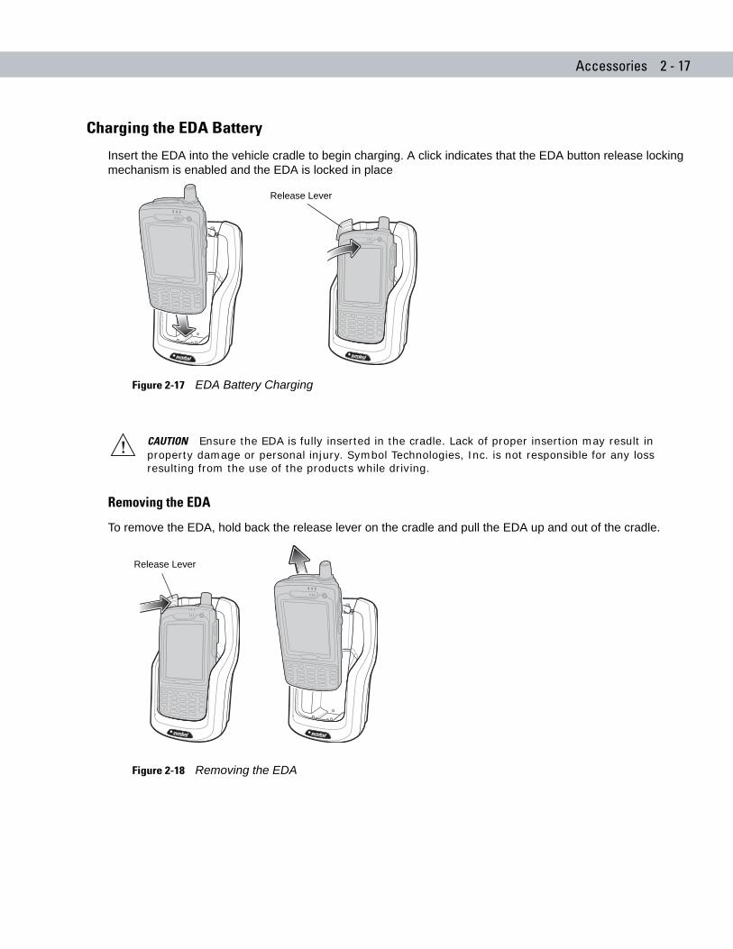
Insert the EDA into the vehicle cradle to begin charging. A click indicates that the EDA button release locking mechanism is enabled and the EDA is locked in place
Figure 2-17 EDA Battery Charging
Removing the EDA
To remove the EDA, hold back the release lever on the cradle and pull the EDA up and out of the cradle.
Figure 2-18 Removing the EDA
CAUTION Ensure the EDA is fully inserted in the cradle. Lack of proper insertion may result in property damage or personal injury. Symbol Technologies, Inc. is not responsible for any loss resulting from the use of the products while driving.
Release Lever
Release Lever
2 - 18 MC70 Integrator Guide
Charging the Spare Battery
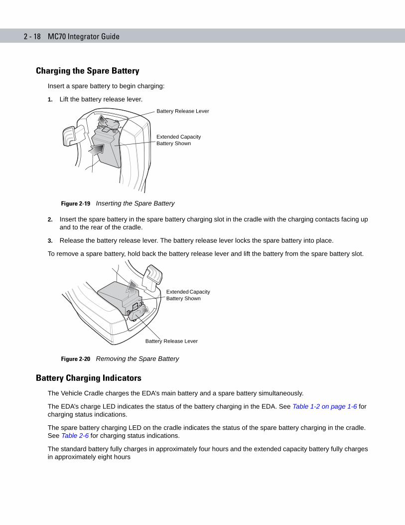
Insert a spare battery to begin charging:
1. Lift the battery release lever.
Figure 2-19 Inserting the Spare Battery
2. Insert the spare battery in the spare battery charging slot in the cradle with the charging contacts facing up and to the rear of the cradle.
3. Release the battery release lever. The battery release lever locks the spare battery into place.
To remove a spare battery, hold back the battery release lever and lift the battery from the spare battery slot.
Figure 2-20 Removing the Spare Battery
Battery Charging Indicators
The Vehicle Cradle charges the EDA’s main battery and a spare battery simultaneously.
The EDA’s charge LED indicates the status of the battery charging in the EDA. See Table 1-2 on page 1-6 for charging status indications.
The spare battery charging LED on the cradle indicates the status of the spare battery charging in the cradle. See Table 2-6 for charging status indications.
The standard battery fully charges in approximately four hours and the extended capacity battery fully charges in approximately eight hours
Extended Capacity Battery Shown
Battery Release Lever
Battery Release Lever
Extended Capacity Battery Shown
Accessories 2 - 19
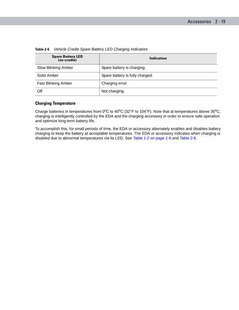
Charging Temperature
Charge batteries in temperatures from 0oC to 40oC (32°F to 104°F). Note that at temperatures above 35oC, charging is intelligently controlled by the EDA and the charging accessory in order to ensure safe operation and optimize long-term battery life.
To accomplish this, for small periods of time, the EDA or accessory alternately enables and disables battery charging to keep the battery at acceptable temperatures. The EDA or accessory indicates when charging is disabled due to abnormal temperatures via its LED. See Table 1-2 on page 1-6 and Table 2-6.
Table 2-6 Vehicle Cradle Spare Battery LED Charging Indicators
Spare Battery LED(on cradle) Indication
Slow Blinking Amber Spare battery is charging.
Solid Amber Spare battery is fully charged.
Fast Blinking Amber Charging error.
Off Not charging.
2 - 20 MC70 Integrator Guide
Four Slot Spare Battery ChargerThis section describes how to use the Four Slot Spare Battery Charger to charge up to four EDA spare batteries.
Battery Shim Installation
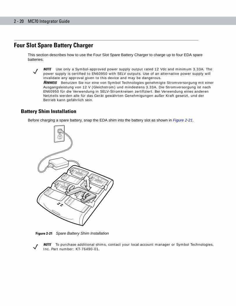
Before charging a spare battery, snap the EDA shim into the battery slot as shown in Figure 2-21.
Figure 2-21 Spare Battery Shim Installation
NOTE Use only a Symbol-approved power supply output rated 12 Vdc and minimum 3.33A. The power supply is certified to EN60950 with SELV outputs. Use of an alternative power supply will invalidate any approval given to this device and may be dangerous.HINWEIS Benutzen Sie nur eine von Symbol Technologies genehmigte Stromversorgung mit einer Ausgangsleistung von 12 V (Gleichstrom) und mindestens 3.33A. Die Stromversorgung ist nach EN60950 für die Verwendung in SELV-Stromkreisen zertifiziert. Bei Verwendung eines anderen Netzteils werden alle für das Gerät gewährten Genehmigungen außer Kraft gesetzt, und der Betrieb kann gefährlich sein.
NOTE To purchase additional shims, contact your local account manager or Symbol Technologies, Inc. Part number: KT-76490-01.
Accessories 2 - 21
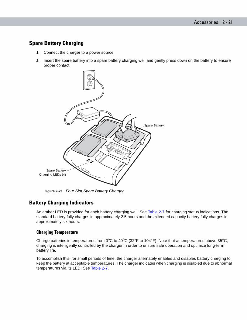
Spare Battery Charging
1. Connect the charger to a power source.
2. Insert the spare battery into a spare battery charging well and gently press down on the battery to ensure proper contact.
Figure 2-22 Four Slot Spare Battery Charger
Battery Charging Indicators
An amber LED is provided for each battery charging well. See Table 2-7 for charging status indications. The standard battery fully charges in approximately 2.5 hours and the extended capacity battery fully charges in approximately six hours.
Charging Temperature
Charge batteries in temperatures from 0oC to 40oC (32°F to 104°F). Note that at temperatures above 35oC, charging is intelligently controlled by the charger in order to ensure safe operation and optimize long-term battery life.
To accomplish this, for small periods of time, the charger alternately enables and disables battery charging to keep the battery at acceptable temperatures. The charger indicates when charging is disabled due to abnormal temperatures via its LED. See Table 2-7.
Spare BatteryCharging LEDs (4)
Spare Battery
2 - 22 MC70 Integrator Guide
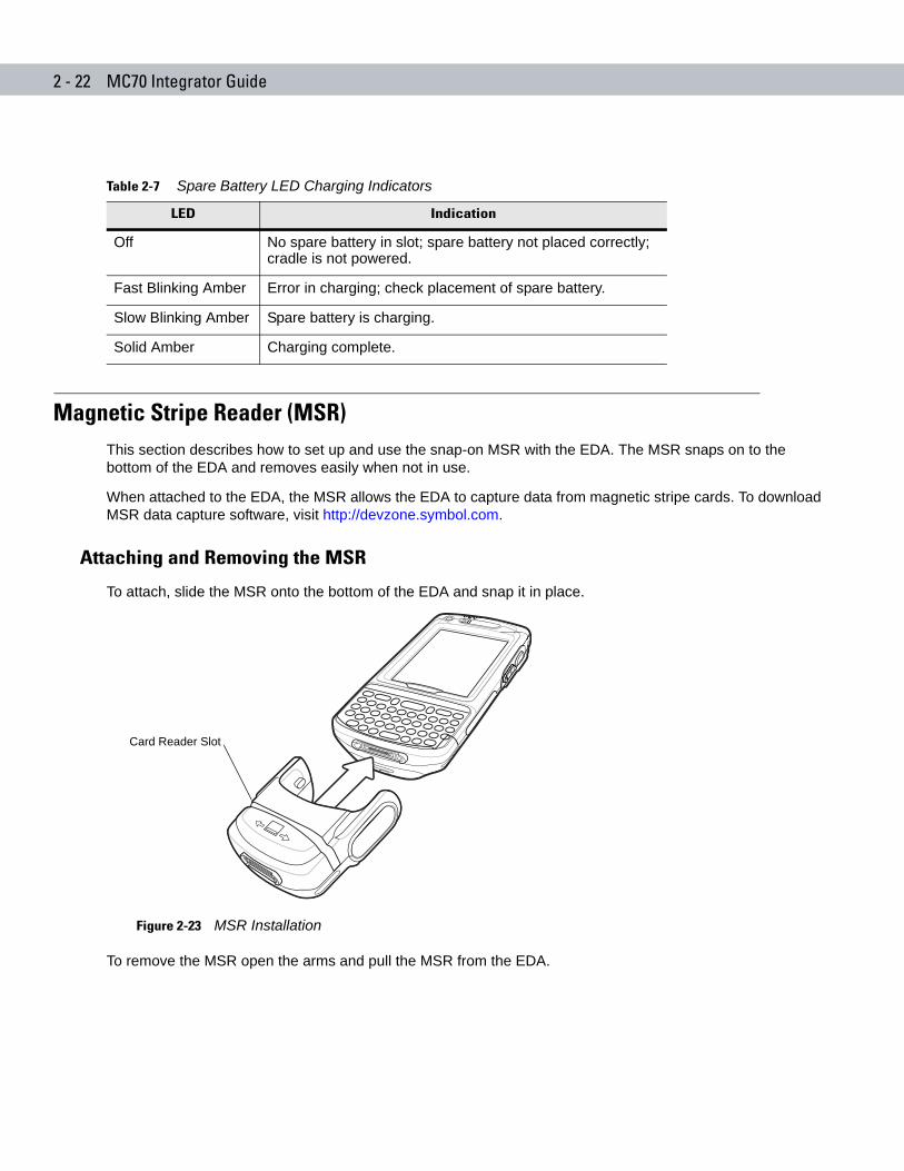
Magnetic Stripe Reader (MSR)This section describes how to set up and use the snap-on MSR with the EDA. The MSR snaps on to the bottom of the EDA and removes easily when not in use.
When attached to the EDA, the MSR allows the EDA to capture data from magnetic stripe cards. To download MSR data capture software, visit http://devzone.symbol.com.
Attaching and Removing the MSR
To attach, slide the MSR onto the bottom of the EDA and snap it in place.
Figure 2-23 MSR Installation
To remove the MSR open the arms and pull the MSR from the EDA.
Table 2-7 Spare Battery LED Charging Indicators
LED Indication
Off No spare battery in slot; spare battery not placed correctly; cradle is not powered.
Fast Blinking Amber Error in charging; check placement of spare battery.
Slow Blinking Amber Spare battery is charging.
Solid Amber Charging complete.
Card Reader Slot
Accessories 2 - 23
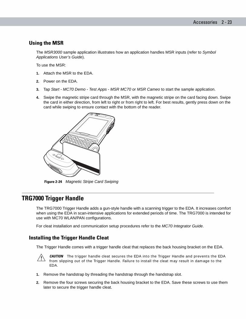
Using the MSR
The MSR3000 sample application illustrates how an application handles MSR inputs (refer to Symbol Applications User’s Guide).
To use the MSR:
1. Attach the MSR to the EDA.
2. Power on the EDA.
3. Tap Start - MC70 Demo - Test Apps - MSR MC70 or MSR Cameo to start the sample application.
4. Swipe the magnetic stripe card through the MSR, with the magnetic stripe on the card facing down. Swipe the card in either direction, from left to right or from right to left. For best results, gently press down on the card while swiping to ensure contact with the bottom of the reader.
Figure 2-24 Magnetic Stripe Card Swiping
TRG7000 Trigger HandleThe TRG7000 Trigger Handle adds a gun-style handle with a scanning trigger to the EDA. It increases comfort when using the EDA in scan-intensive applications for extended periods of time. The TRG7000 is intended for use with MC70 WLAN/PAN configurations.
For cleat installation and communication setup procedures refer to the MC70 Integrator Guide.
Installing the Trigger Handle Cleat
The Trigger Handle comes with a trigger handle cleat that replaces the back housing bracket on the EDA.
1. Remove the handstrap by threading the handstrap through the handstrap slot.
2. Remove the four screws securing the back housing bracket to the EDA. Save these screws to use them later to secure the trigger handle cleat.
CAUTION The trigger handle cleat secures the EDA into the Trigger Handle and prevents the EDA from slipping out of the Trigger Handle. Failure to install the cleat may result in damage to the EDA.

2 - 24 MC70 Integrator Guide
3. Remove the back housing bracket.
Figure 2-25 Removing Back Housing Bracket
4. Install the rubber headset jack dust cover onto the trigger handle cleat.
5. Align the trigger handle cleat onto the EDA.
6. Secure the trigger handle cleat to the EDA using the four screws saved during step 2.
Figure 2-26 Installing the Cleat
7. Feed the handstrap through the handstrap slot and secure.
Inserting the EDA into the Trigger Handle
Slide the EDA into the Trigger Handle until it locks in place. The release secures the EDA to the Trigger Handle.
Figure 2-27 Inserting the EDA into the Trigger Handle
BackHousingBracket
Release
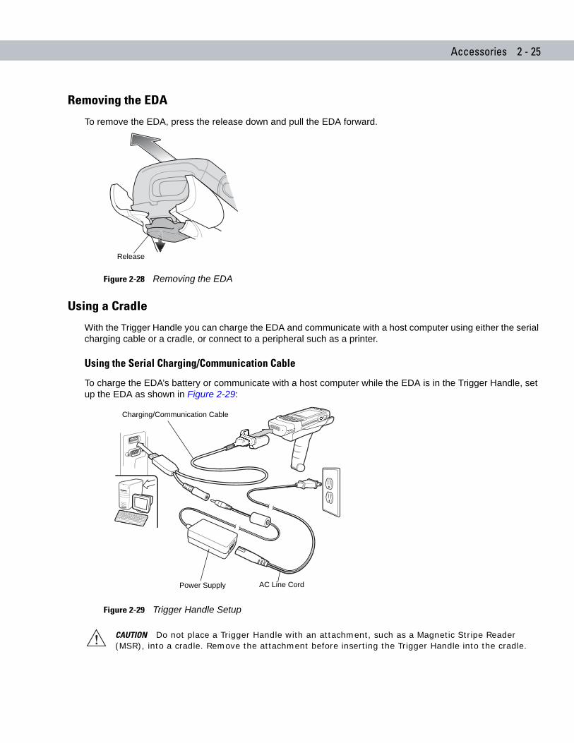
Accessories 2 - 25
Removing the EDA
To remove the EDA, press the release down and pull the EDA forward.
Figure 2-28 Removing the EDA
Using a Cradle
With the Trigger Handle you can charge the EDA and communicate with a host computer using either the serial charging cable or a cradle, or connect to a peripheral such as a printer.
Using the Serial Charging/Communication Cable
To charge the EDA’s battery or communicate with a host computer while the EDA is in the Trigger Handle, set up the EDA as shown in Figure 2-29:
Figure 2-29 Trigger Handle Setup
Release
CAUTION Do not place a Trigger Handle with an attachment, such as a Magnetic Stripe Reader (MSR), into a cradle. Remove the attachment before inserting the Trigger Handle into the cradle.
Power Supply AC Line Cord
Charging/Communication Cable
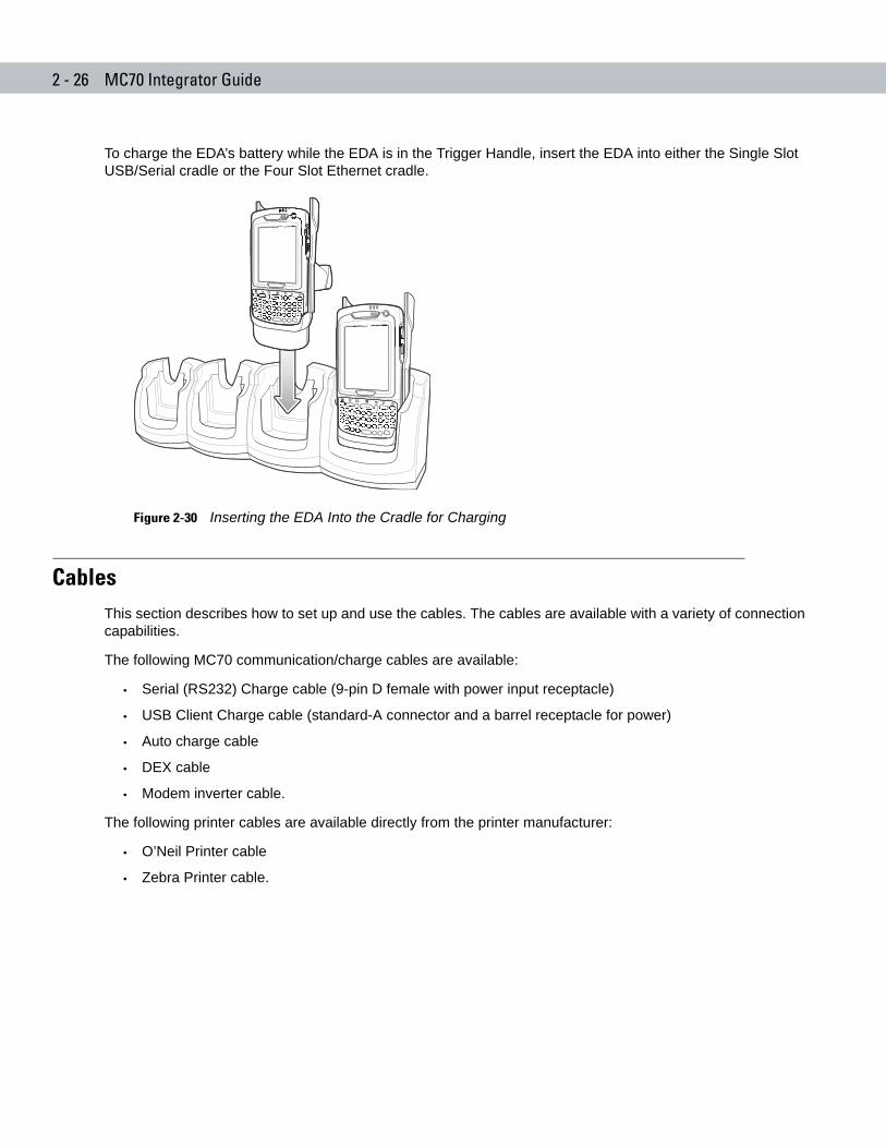
2 - 26 MC70 Integrator Guide
To charge the EDA’s battery while the EDA is in the Trigger Handle, insert the EDA into either the Single Slot USB/Serial cradle or the Four Slot Ethernet cradle.
Figure 2-30 Inserting the EDA Into the Cradle for Charging
CablesThis section describes how to set up and use the cables. The cables are available with a variety of connection capabilities.
The following MC70 communication/charge cables are available:
• Serial (RS232) Charge cable (9-pin D female with power input receptacle)
• USB Client Charge cable (standard-A connector and a barrel receptacle for power)
• Auto charge cable
• DEX cable
• Modem inverter cable.
The following printer cables are available directly from the printer manufacturer:
• O’Neil Printer cable
• Zebra Printer cable.
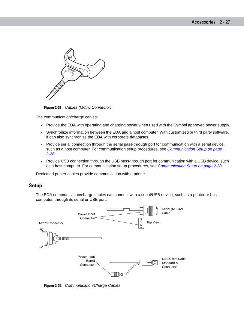
Accessories 2 - 27
Figure 2-31 Cables (MC70 Connector)
The communication/charge cables:
• Provide the EDA with operating and charging power when used with the Symbol approved power supply.
• Synchronize information between the EDA and a host computer. With customized or third party software, it can also synchronize the EDA with corporate databases.
• Provide serial connection through the serial pass-through port for communication with a serial device, such as a host computer. For communication setup procedures, see Communication Setup on page 2-28.
• Provide USB connection through the USB pass-through port for communication with a USB device, such as a host computer. For communication setup procedures, see Communication Setup on page 2-28.
Dedicated printer cables provide communication with a printer.
Setup
The EDA communication/charge cables can connect with a serial/USB device, such as a printer or host computer, through its serial or USB port.
Figure 2-32 Communication/Charge Cables
USB Host Cable Mini-B
MC70 Connector
Power InputBarrel
Connector
Serial (RS232) Cable
USB Client Cable Standard-A Connector
Power InputConnector
Top View
2 - 28 MC70 Integrator Guide
Battery Charging
The communication/charge cables can charge the EDA battery and supply operating power.
To charge the EDA battery:
1. Connect the communication/charge cable power input connector to the Symbol approved power source.
2. Slide the bottom of the EDA into the connector end of the communication/charge cable and gently press in until it latches into the EDA. The EDA amber Charge LED indicates the EDA battery charging status. The standard battery charges in less than four hours and the extended capacity battery charges in less than six hours. See Table 1-2 on page 1-6 for charging status indications.
3. When charging completes, remove the cable by gently pulling the EDA and the cable apart.
LED Charge Indications
The amber Charge LED on the EDA indicates battery charging status. See Table 1-2 on page 1-6 for charging status indications.
Charging Temperature
Charge batteries in temperatures from 0oC to 40oC (32°F to 104°F). Note that at temperatures above 35oC, charging is intelligently controlled by the EDA in order to ensure safe operation and optimize long-term battery life.
To accomplish this, for small periods of time, the EDA alternately enables and disables battery charging to keep the battery at acceptable temperatures. The EDA indicates when charging is disabled due to abnormal temperatures via its LED. See Table 1-2 on page 1-6.
Communication Setup
To connect an EDA communication/charge cable to a serial or USB device:
1. Connect the serial/USB end of the EDA communication/charge cable to the communication port of the device.
2. Connect the EDA connector end of the cable to the EDA. For more information on communication setup procedures, see Chapter 3, ActiveSync.
Chapter 3 ActiveSync
Chapter 3
Chapter 3 ActiveSyncIntroductionTo communicate with various host devices, install Microsoft ActiveSync (version 4.1 or higher) on the host computer. Use ActiveSync to synchronize information on the EDA with information on the host computer. Changes made on the EDA or host computer appear in both places after synchronization.
ActiveSync software:
• Allows working with EDA-compatible host applications on the host computer. ActiveSync replicates data from the EDA so the host application can view, enter, and modify data on the EDA.
• Synchronizes files between the EDA and host computer, converting the files to the correct format.
• Backs up the data stored on the EDA. Synchronization is a one-step procedure that ensures the data is always safe and up-to-date.
• Copies (rather than synchronizes) files between the EDA and host computer.
• Controls when synchronization occurs by selecting a synchronization mode, e.g., set to synchronize continually while the EDA is connected to the host computer, or set to only synchronize on command.
• Selects the types of information to synchronize and control how much data is synchronized.
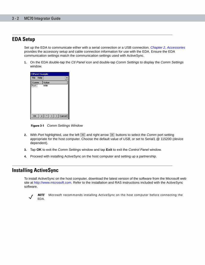
3 - 2 MC70 Integrator Guide
EDA SetupSet up the EDA to communicate either with a serial connection or a USB connection. Chapter 2, Accessories provides the accessory setup and cable connection information for use with the EDA. Ensure the EDA communication settings match the communication settings used with ActiveSync.
1. On the EDA double-tap the Ctl Panel icon and double-tap Comm Settings to display the Comm Settings window.
Figure 3-1 Comm Settings Window
2. With Port highlighted, use the left and right arrow buttons to select the Comm port setting appropriate for the host computer. Choose the default value of USB, or set to Serial1 @ 115200 (device dependent).
3. Tap OK to exit the Comm Settings window and tap Exit to exit the Control Panel window.
4. Proceed with installing ActiveSync on the host computer and setting up a partnership.
Installing ActiveSyncTo install ActiveSync on the host computer, download the latest version of the software from the Microsoft web site at http://www.microsoft.com. Refer to the installation and RAS instructions included with the ActiveSync software.
NOTE Microsoft recommends installing ActiveSync on the host computer before connecting the EDA.
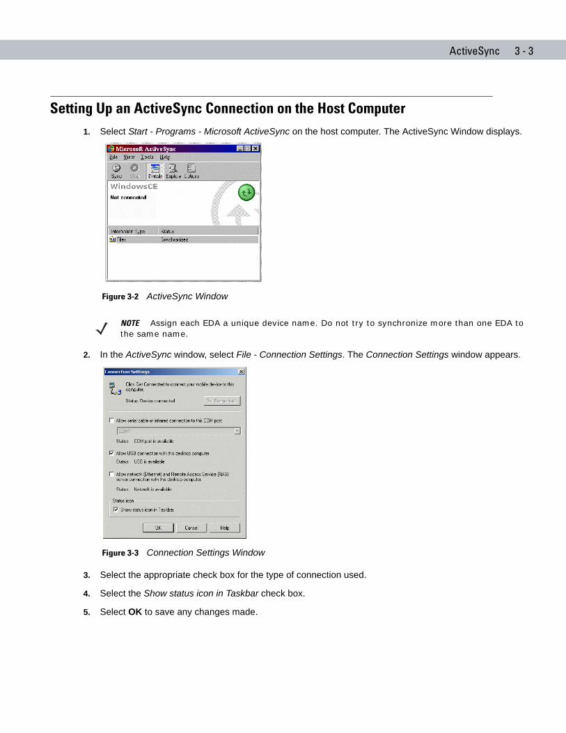
ActiveSync 3 - 3
Setting Up an ActiveSync Connection on the Host Computer1. Select Start - Programs - Microsoft ActiveSync on the host computer. The ActiveSync Window displays.
Figure 3-2 ActiveSync Window
2. In the ActiveSync window, select File - Connection Settings. The Connection Settings window appears.
Figure 3-3 Connection Settings Window
3. Select the appropriate check box for the type of connection used.
4. Select the Show status icon in Taskbar check box.
5. Select OK to save any changes made.
NOTE Assign each EDA a unique device name. Do not try to synchronize more than one EDA to the same name.
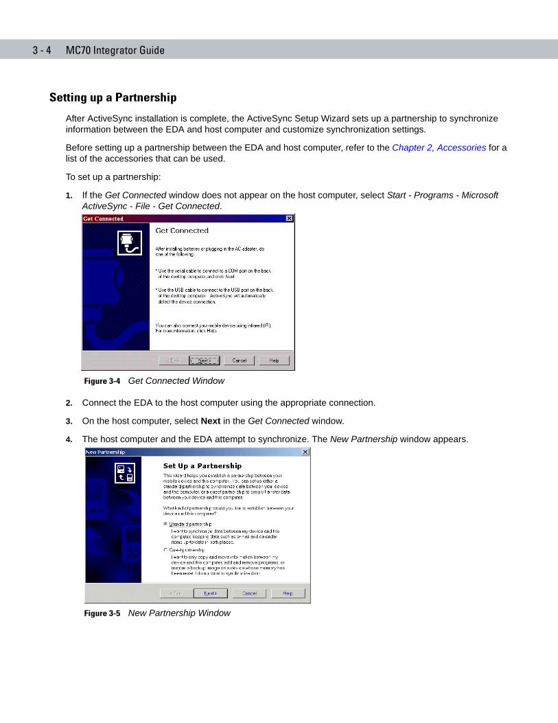
3 - 4 MC70 Integrator Guide
Setting up a Partnership
After ActiveSync installation is complete, the ActiveSync Setup Wizard sets up a partnership to synchronize information between the EDA and host computer and customize synchronization settings.
Before setting up a partnership between the EDA and host computer, refer to the Chapter 2, Accessories for a list of the accessories that can be used.
To set up a partnership:
1. If the Get Connected window does not appear on the host computer, select Start - Programs - Microsoft ActiveSync - File - Get Connected.
Figure 3-4 Get Connected Window
2. Connect the EDA to the host computer using the appropriate connection.
3. On the host computer, select Next in the Get Connected window.
4. The host computer and the EDA attempt to synchronize. The New Partnership window appears.
Figure 3-5 New Partnership Window
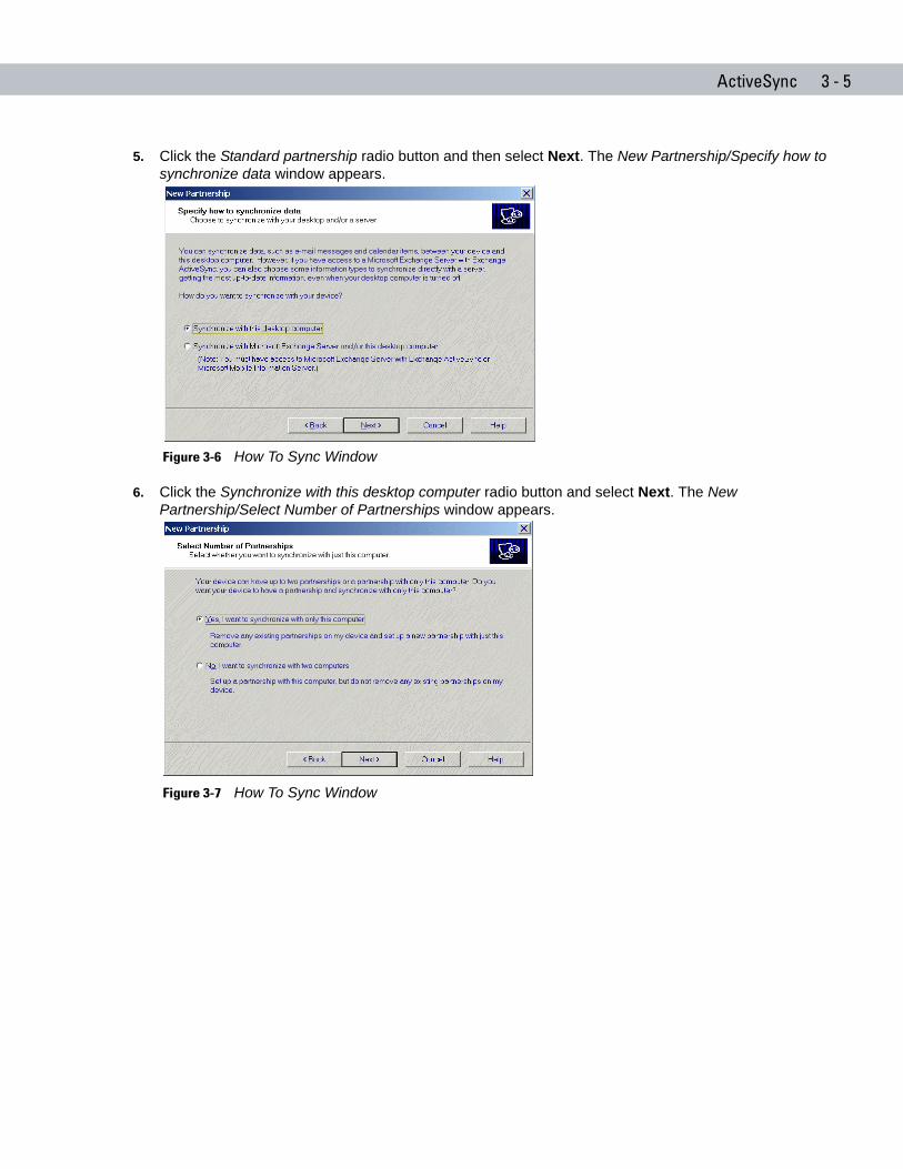
ActiveSync 3 - 5
5. Click the Standard partnership radio button and then select Next. The New Partnership/Specify how to synchronize data window appears.
Figure 3-6 How To Sync Window
6. Click the Synchronize with this desktop computer radio button and select Next. The New Partnership/Select Number of Partnerships window appears.
Figure 3-7 How To Sync Window
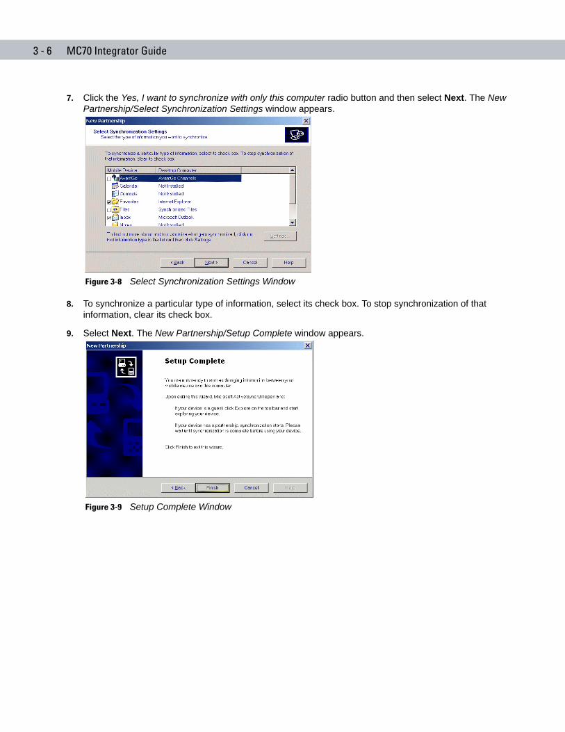
3 - 6 MC70 Integrator Guide
7. Click the Yes, I want to synchronize with only this computer radio button and then select Next. The New Partnership/Select Synchronization Settings window appears.
Figure 3-8 Select Synchronization Settings Window
8. To synchronize a particular type of information, select its check box. To stop synchronization of that information, clear its check box.
9. Select Next. The New Partnership/Setup Complete window appears.
Figure 3-9 Setup Complete Window
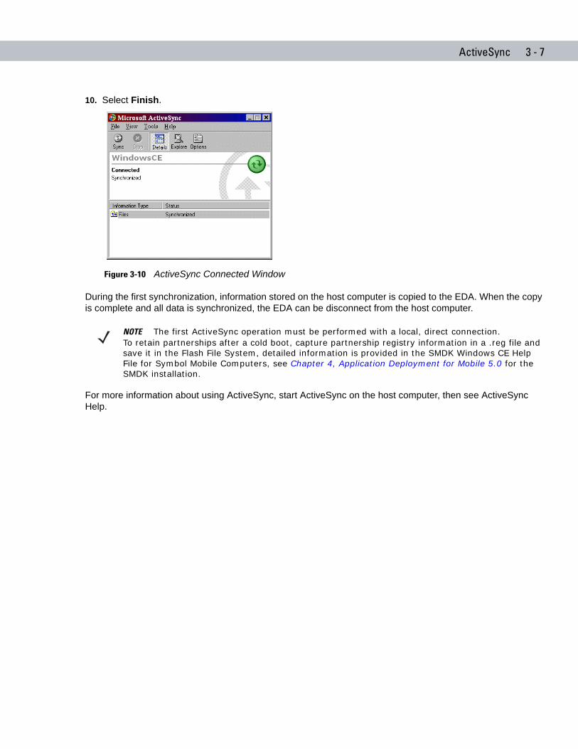
ActiveSync 3 - 7
10. Select Finish.
Figure 3-10 ActiveSync Connected Window
During the first synchronization, information stored on the host computer is copied to the EDA. When the copy is complete and all data is synchronized, the EDA can be disconnect from the host computer.
For more information about using ActiveSync, start ActiveSync on the host computer, then see ActiveSync Help.
NOTE The first ActiveSync operation must be performed with a local, direct connection.To retain partnerships after a cold boot, capture partnership registry information in a .reg file and save it in the Flash File System, detailed information is provided in the SMDK Windows CE Help File for Symbol Mobile Computers, see Chapter 4, Application Deployment for Mobile 5.0 for the SMDK installation.

3 - 8 MC70 Integrator Guide
Chapter 4 Application Deployment for Mobile 5.0
Chapter 4
Chapter 4 Application Deployment for Mobile 5.0IntroductionThis chapter describes new features in Windows Mobile 5.0 including new security features, how to package applications, and procedures for deploying applications onto the EDA.
SecurityThe MC70 EDAs implement a set of security policies that determine whether an application is allowed to run and, if allowed, with what level of trust. To develop an application, you must know the security configuration of the device, and how to sign an application with the appropriate certificate to allow the application to run (and to run with the needed level of trust).
Application Security
Application security controls the applications that can run on the EDA.
• Trusted - All applications must be digitally signed by a certificate on the EDA.
• Prompted - User is prompted to allow unsigned applications to run.
• Open - All applications run.
Developers can include their own certificates and provision the device to “trusted.”
Digital Signatures
Digital signatures provide a way to authenticate the author of EXEs, DLLs, and packages. Digitally signed applications give users confidence that an application comes from where they think it comes from. For example, if an end-user downloads an update package from the internet that is digitally signed with Symbol's software certificate, they are assured that the package is authentic and that it was created by Symbol. By enforcing the use of digital signatures, users can also prevent malicious applications from executing on the EDA. For example, users can provision the EDA to only execute “trusted” applications (digitally signed).
Symbol ships all Windows Mobile 5.0 based products in an “open” state, which means all signed and unsigned applications should work. However, customers can still reconfigure their EDAs to operate in the “trusted” mode. This means that only applications signed with a certificate from the Privileged Execution Trust Certificate Store can run.
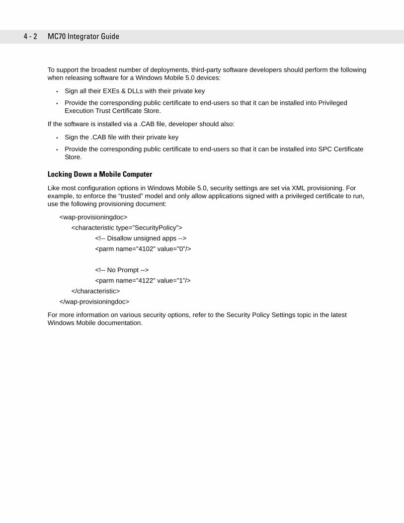
4 - 2 MC70 Integrator Guide
To support the broadest number of deployments, third-party software developers should perform the following when releasing software for a Windows Mobile 5.0 devices:
• Sign all their EXEs & DLLs with their private key
• Provide the corresponding public certificate to end-users so that it can be installed into Privileged Execution Trust Certificate Store.
If the software is installed via a .CAB file, developer should also:
• Sign the .CAB file with their private key
• Provide the corresponding public certificate to end-users so that it can be installed into SPC Certificate Store.
Locking Down a Mobile Computer
Like most configuration options in Windows Mobile 5.0, security settings are set via XML provisioning. For example, to enforce the “trusted” model and only allow applications signed with a privileged certificate to run, use the following provisioning document:
<wap-provisioningdoc><characteristic type="SecurityPolicy”>
<!-- Disallow unsigned apps --><parm name="4102" value="0"/>
<!-- No Prompt --><parm name=”4122" value=”1”/>
</characteristic></wap-provisioningdoc>
For more information on various security options, refer to the Security Policy Settings topic in the latest Windows Mobile documentation.
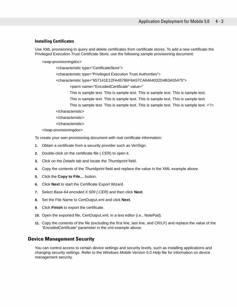
Application Deployment for Mobile 5.0 4 - 3
Installing Certificates
Use XML provisioning to query and delete certificates from certificate stores. To add a new certificate the Privileged Execution Trust Certificate Store, use the following sample provisioning document:
<wap-provisioningdoc> <characteristic type=”CertificateStore”> <characteristic type=”Privileged Execution Trust Authorities”> <characteristic type=”657141E12FA45786F6A57CA6464032D4B3A55475">
<parm name=”EncodedCertificate" value=" This is sample text. This is sample text. This is sample text. This is sample text. This is sample text. This is sample text. This is sample text. This is sample text. This is sample text. This is sample text. This is sample text. This is sample text. ="/>
</characteristic> </characteristic> </characteristic>
</wap-provisioningdoc>
To create your own provisioning document with real certificate information:
1. Obtain a certificate from a security provider such as VeriSign.
2. Double-click on the certificate file (.CER) to open it.
3. Click on the Details tab and locate the Thumbprint field.
4. Copy the contents of the Thumbprint field and replace the value in the XML example above.
5. Click the Copy to File… button.
6. Click Next to start the Certificate Export Wizard.
7. Select Base-64 encoded X.509 (.CER) and then click Next.
8. Set the File Name to CertOutput.xml and click Next.
9. Click Finish to export the certificate.
10. Open the exported file, CertOutput.xml, in a text editor (i.e., NotePad).
11. Copy the contents of the file (excluding the first line, last line, and CR/LF) and replace the value of the “EncodedCertificate” parameter in the xml example above.
Device Management Security
You can control access to certain device settings and security levels, such as installing applications and changing security settings. Refer to the Windows Mobile Version 5.0 Help file for information on device management security.
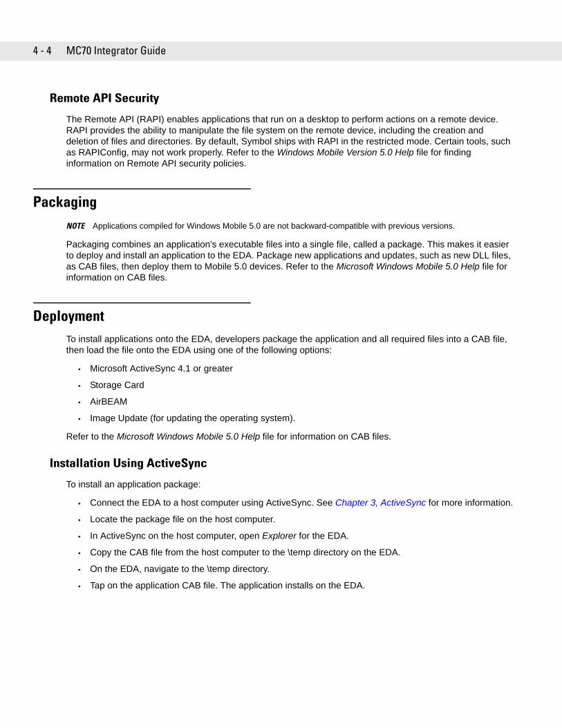
4 - 4 MC70 Integrator Guide
Remote API Security
The Remote API (RAPI) enables applications that run on a desktop to perform actions on a remote device. RAPI provides the ability to manipulate the file system on the remote device, including the creation and deletion of files and directories. By default, Symbol ships with RAPI in the restricted mode. Certain tools, such as RAPIConfig, may not work properly. Refer to the Windows Mobile Version 5.0 Help file for finding information on Remote API security policies.
PackagingNOTE Applications compiled for Windows Mobile 5.0 are not backward-compatible with previous versions.
Packaging combines an application's executable files into a single file, called a package. This makes it easier to deploy and install an application to the EDA. Package new applications and updates, such as new DLL files, as CAB files, then deploy them to Mobile 5.0 devices. Refer to the Microsoft Windows Mobile 5.0 Help file for information on CAB files.
DeploymentTo install applications onto the EDA, developers package the application and all required files into a CAB file, then load the file onto the EDA using one of the following options:
• Microsoft ActiveSync 4.1 or greater
• Storage Card
• AirBEAM
• Image Update (for updating the operating system).
Refer to the Microsoft Windows Mobile 5.0 Help file for information on CAB files.
Installation Using ActiveSync
To install an application package:
• Connect the EDA to a host computer using ActiveSync. See Chapter 3, ActiveSync for more information.
• Locate the package file on the host computer.
• In ActiveSync on the host computer, open Explorer for the EDA.
• Copy the CAB file from the host computer to the \temp directory on the EDA.
• On the EDA, navigate to the \temp directory.
• Tap on the application CAB file. The application installs on the EDA.
Application Deployment for Mobile 5.0 4 - 5
Installation Using Storage Card
To install an application package:
• Copy the package CAB file to a storage card using an appropriate storage card reader.
• Install the storage card into the EDA. See Multi Media Card (MMC) / Secure Digital (SD) Card on page 2-2 for more information.
• On the EDA, open File Explorer.
• Open the Storage Card directory.
• Tap the package CAB file. The application installs on the EDA.
Installation Using AirBEAM
See AirBEAM Smart on page 4-16 for information on AirBEAM.
Image Update
Windows Mobile 5.0 contains an Image Update feature that updates all operating system components. All updates are distributed as update packages. Update packages can contain either partial or complete updates for the operating system. Symbol distributes the update packages on the Symbol Developer Web Site, http://devzone.symbol.com.
To update an operating system component, copy the update package to the EDA using one of a variety of transports, including ActiveSync, an SD memory card, or Symbol AirBEAM. Then, initiate the update using one of the following methods:
• Double-tap the package file in File Explorer (similar to extracting a CAB file)
• Perform a special boot sequence that initiates the update.
• Use AirBEAM.
To initiate an update:
1. Go to the Symbol Developer Zone web site, http://devzone.symbol.com.
2. Download the appropriate update package.
3. Copy the update package to either the \temp directory on the EDA, or to a storage card.
4. Connect the EDA to AC power. See Chapter 2, Accessories.
5. Cold boot the EDA. See Resetting the EDA on page 1-7.
6. The Update Loader application first looks for a file on a storage card. If it does not find it, it looks in the \temp directory.
When it finds the appropriate file, it loads the package onto the EDA. A progress bar displays until the update completes.
7. The EDA a warm boots.
NOTE The EDA must have at least 5 MB of free space to perform an OS update.
4 - 6 MC70 Integrator Guide
Creating a Splash Screen
Use a bitmap file to create a customized splash screens for the EDA. Use Image Update with a bitmap file, rather than a package file, to update the splash screen.
To create a custom splash screen:
1. Create a .bmp file using a graphic program with the following specifications:
• Size: 240 x 296.
• Colors: 8 bits per pixel (256 colors) for color displays.
2. Modify the bitmap file and save.
To load the splash screen on the EDA:
1. Create a text file named pkgs.lst which contains the name of the bmp file. For example, mysplash.bmp.
2. Copy the bmp file and the pkgs.lst file to one of the following:
• SD card root directory
• EDA’s \temp directory
• EDA’s \Windows directory.
3. If using an SD card, insert the SD card into the EDA.
4. Perform a cold boot.
5. Press the trigger or side scan button for 5 seconds while booting to invoke the Update Loader and install the splash screen.
XML Provisioning To configure the settings on an EDA, use XML provisioning. To install an XML provisioning file on the EDA, create a Cabinet Provisioning File (CPF). A CPF file is similar to a CAB file and contains just one file: _setup.xml. Like a CAB file, the CPF extension is associated with WCELoad.EXE. Opening a CPF extracts the XML code and uses it to provision and configure the EDA. The user receives an e-mail notification indicating success or failure.
XML provisioning provides the ability to configure varoius features of the EDA (i.e., registry and file system). However, some settings require security priviledges. To change registry settings via a CPF file, you must have certain privileges (roles). Some registry keys require you to simply be an Authenticated User, while other registry keys require you to be a Manager. Refer to the Microsoft Windows Mobile 5.0 Help file, Metabase Settings for Registry Configuration Service Provider section, for the default role settings in Windows Mobile 5.0.
NOTE When initiating an update via a boot sequence, the update loader looks for updates first on the root of an installed SD card and then in the \temp folder on the EDA’s persistent storage volume. A response file, pkgs.lst, indicates which files to update. In most cases, Symbol provides this pkgs.lst file with the update and you should only modify it when updating a splash screen partition. See Creating a Splash Screen for more information.
Application Deployment for Mobile 5.0 4 - 7
For those registry settings that require the Manager role, the CPF file must be signed with a priviliged certificate installed on the device. Refer to the Microsoft Windows Mobile 5.0 Help file and the Windows Mobile 5.0 SDK for instructions and sample test certificates.
Creating an XML Provisioning File
To create a .cpf file:
1. Create a valid provisioning XML file named _setup.xml using an XML editor or the tools supplied with Visual Studio 2005. (For example, use the SampleReg.xml sample created in the RegMerge section and rename it _setup.xml.) Ensure the file contains the required parameters for the operation. Refer to the Microsoft Windows Mobile 5.0 Help file for information.
2. In the Windows Mobile 5.0 tools directory on the desktop computer (typically \Program Files\Windows CE Tools\wce500\Windows Mobile 5.0 Pocket PC SDK\Tools), run the Makecab.exe utility, using the following syntax to create a .cpf file from the _setup.xml file:MakeCab.exe /D COMPRESS=OFF _setup.xml myOutCpf
3. Optionally, use the Authenticode tools to sign the .cpf file.
4. Tap the filename to install.
5. Certain applications and settings require a cold boot to take affect. In these cases, cold boot the EDA. Refer to the Windows Mobile Version 5.0 Help file for more information.
XML Provisioning vs. RegMerge and Copy File
Prior to Windows Mobile 5.0, Symbol used two drivers (RegMerge and CopyFiles) to update the registry and to copy files during a cold boot. With Mobile 5.0, Symbol recommends using XML provisioning instead. RegMerge and CopyFiles are supported for backward compatibility but Symbol may eliminate support in the future. The following sections provide examples of how RegMerge and CopyFiles were used, and how to perform the same function using XML provisioning.
RegMerge
RegMerge.dll is a built-in driver that allows updating the registry during a clean boot. RegMerge runs very early in the boot process and looks for registry files (.reg files) in certain Flash File System folders (i.e., \Application) during a clean boot. It then merges the registry changes into the system registry located in RAM.
The following example uses RegMerge to set a registry key:
SampleReg.reg
[HKEY_LOCAL_MACHINE\Hardware\DeviceMap\Backlight]"BacklightIntensity"=dword:00000036
NOTE COMPRESS=OFF is required for backward compatability with Pocket PC.
4 - 8 MC70 Integrator Guide
The following example uses XML provisioning to perform the same task:
SampleReg.xml
<wap-provisioningdoc><characteristic type="Registry">
<characteristic type="HKLM\Hardware\DeviceMap\Backlight"><parm name="BacklightIntensity" value="54" datatype="integer" />
</characteristic></characteristic>
</wap-provisioningdoc>
CopyFiles
CopyFiles copies files from one folder to another on a clean boot. During a clean boot CopyFiles looks for files with a .CPY extension in the root of the Application FFS partition. These files are text files containing the source and destination for the desired files to copy, separated by “>”.
The following example uses CopyFiles to copy a file from the \Application folder to the \Windows folder:
SampleCpy.cpy
\Application\example.txt > \Windows\example.txt
The following example uses XML provisioning to perform the same task:
SampleCpy.xml
<wap-provisioningdoc><characteristic type="FileOperation">
<characteristic type="\Windows" translation="filesystem"><characteristic type="MakeDir"/><characteristic type="example.txt" translation="fileystem">
<characteristic type="Copy"><parm name="Source" value="\Application\example.txt" translation="filesystem"/>
</characteristic></characteristic>
</characteristic></characteristic>
</wap-provisioningdoc>
Application Deployment for Mobile 5.0 4 - 9
StorageMobile 5.0 contains three types of file storage:
• Random Access Memory (RAM)
• Persistent Storage
• Application folder.
Random Access Memory
Executing programs use RAM to store data. Data stored in RAM is lost upon a warm boot. RAM also included a volatile file storage area called Cache Disk.
Volatile File Storage (Cache Disk)
Windows Mobile 5.0 memory architecture uses persistent storage for all files, registry settings, and database objects to ensure data is retained even after a power failure. Persistent storage is implemented using Flash memory technology which is generally slower than volatile RAM memory. In certain situations the speed of the operation is more important than the integrity of the data. For these situations, Symbol has provided a small volatile File Storage volume, accessed as the Cache Disk folder. Disk operations to the Cache Disk folder are much faster than to any of the persistent storage volumes, but data is lost across warm boots and power interruptions. Note that a backup battery powers RAM memory, including the Cache Disk, when you remove the main battery for a short period of time.
The EDA uses the Cache Disk for temporary data that can be restored from other sources, for example, for temporarily “caching” HTML web pages by a browser or generating formatted files to send to a printer. Both situations benefit from the increased speed of the cache disk, but you can restore the data if needed.
DO NOT use the Cache Disk as a method to improve application performance. Analyze applications that perform slower in persistent storage to optimize disk access. Common areas for optimization include minimizing the number of reads and writes to a file, removing unneeded debug logging, and minimizing file flushing or closing files.
Persistent Storage
Windows Mobile 5.0 protects all data and applications from power-related loss. Because Windows Mobile 5.0 mounts the entire file system and registry in persistent storage (rather than using RAM), MC70 devices provide a reliable storage platform even in the absence of battery power.
Persistent storage provides application developers with a reliable storage system available through the standard file system and registry APIs. Persistent storage is optimized for large reads and writes; therefore, applications reading and writing data in large chunks tend to outperform those applications reading and writing small blocks of data. Data in persistent storage is lost upon a clean boot.
Persistent storage contains all the directories under the root directory except for Application, Cache Disk, and Storage Card (if a storage card is installed). Persistent storage is approximately 60 MB (formatted).
4 - 10 MC70 Integrator Guide
Application Folder
The Application folder is a super-persistent storage that is persistent even after a clean boot. Accessing data in the Application folder is slower than accessing persistent storage. The Application folder is used for deployment and device-unique data. For example, network profiles can be stored in the Application folder so that connection to the network is available after a cold boot. The Application folder is approximately 20 MB (formatted).
System Configuration ManagerSymbol Configuration Manager (SCM) is a utility that runs on the development computer and is used to create configuration files. These files, when deployed to an EDA, set configuration parameters for that device. The configurable options for a EDA are defined in an XML file that is available on the Symbol DevZone for that EDA. SCM is also available on Symbol DevZone.
SCM eliminates the potential user errors that occur when manually editing registry settings.
File Types
SCM uses three types of files:
• Symbol Configuration Template (.SCT) files are XML files that define the configurable parameters for a device.
• Registry Configuration Service Provider XML files for device provisioning.
• CAB Provisioning Format (.CPF) file which is a .CAB archive that contains the provisioning XML. This file is downloaded to the EDA and merged upon a cold boot.
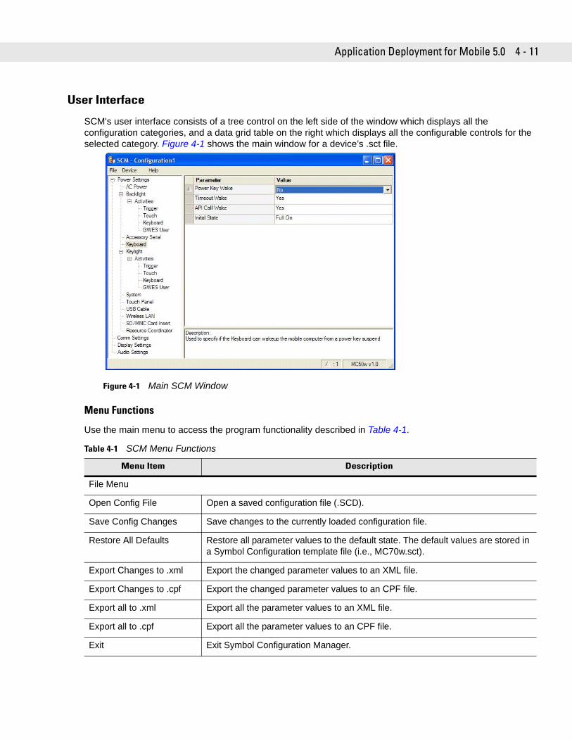
Application Deployment for Mobile 5.0 4 - 11
User Interface
SCM's user interface consists of a tree control on the left side of the window which displays all the configuration categories, and a data grid table on the right which displays all the configurable controls for the selected category. Figure 4-1 shows the main window for a device’s .sct file.
Figure 4-1 Main SCM Window
Menu Functions
Use the main menu to access the program functionality described in Table 4-1.
Table 4-1 SCM Menu Functions
Menu Item Description
File Menu
Open Config File Open a saved configuration file (.SCD).
Save Config Changes Save changes to the currently loaded configuration file.
Restore All Defaults Restore all parameter values to the default state. The default values are stored in a Symbol Configuration template file (i.e., MC70w.sct).
Export Changes to .xml Export the changed parameter values to an XML file.
Export Changes to .cpf Export the changed parameter values to an CPF file.
Export all to .xml Export all the parameter values to an XML file.
Export all to .cpf Export all the parameter values to an CPF file.
Exit Exit Symbol Configuration Manager.
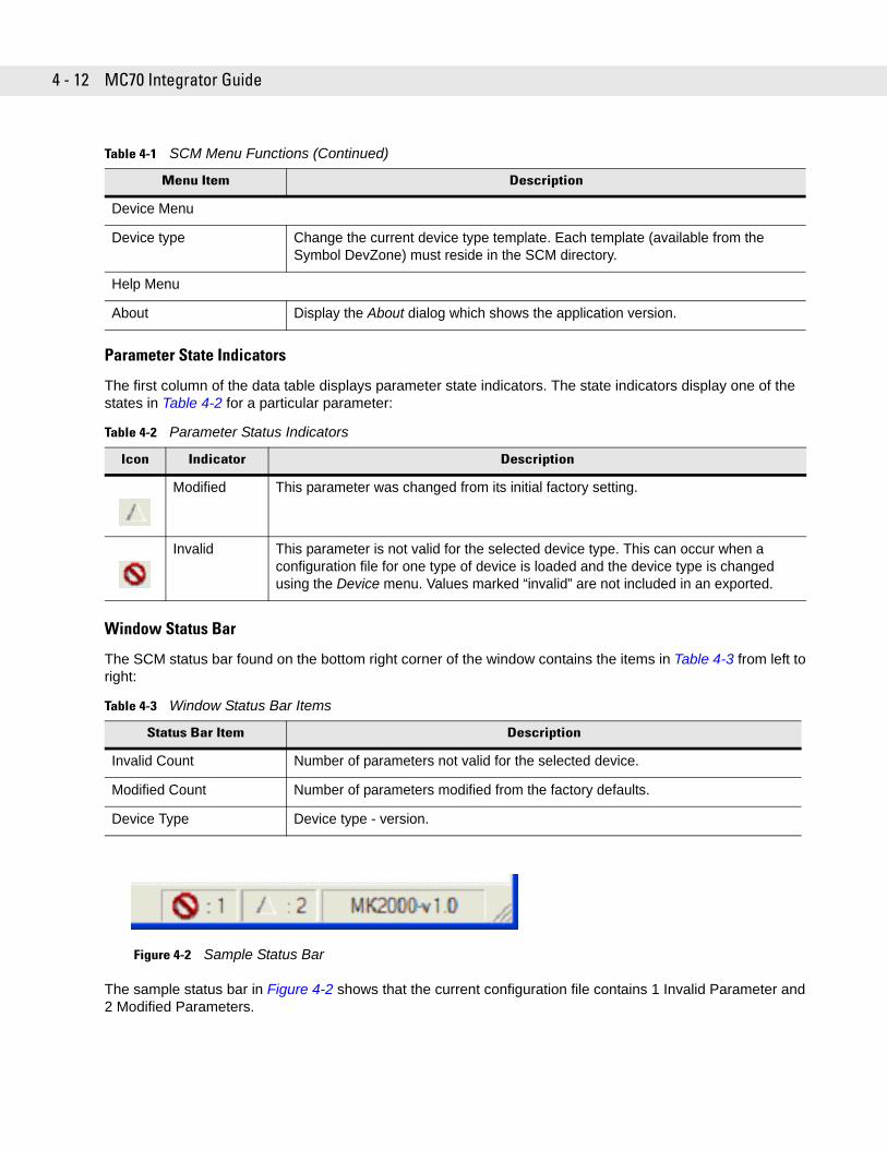
4 - 12 MC70 Integrator Guide
Parameter State Indicators
The first column of the data table displays parameter state indicators. The state indicators display one of the states in Table 4-2 for a particular parameter:
Window Status Bar
The SCM status bar found on the bottom right corner of the window contains the items in Table 4-3 from left to right:
Figure 4-2 Sample Status Bar
The sample status bar in Figure 4-2 shows that the current configuration file contains 1 Invalid Parameter and 2 Modified Parameters.
Device Menu
Device type Change the current device type template. Each template (available from the Symbol DevZone) must reside in the SCM directory.
Help Menu
About Display the About dialog which shows the application version.
Table 4-2 Parameter Status Indicators
Icon Indicator Description
Modified This parameter was changed from its initial factory setting.
Invalid This parameter is not valid for the selected device type. This can occur when a configuration file for one type of device is loaded and the device type is changed using the Device menu. Values marked “invalid” are not included in an exported.
Table 4-3 Window Status Bar Items
Status Bar Item Description
Invalid Count Number of parameters not valid for the selected device.
Modified Count Number of parameters modified from the factory defaults.
Device Type Device type - version.
Table 4-1 SCM Menu Functions (Continued)
Menu Item Description
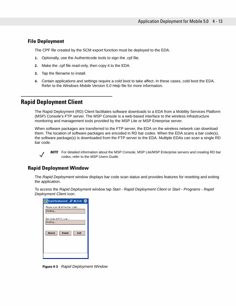
Application Deployment for Mobile 5.0 4 - 13
File Deployment
The CPF file created by the SCM export function must be deployed to the EDA.
1. Optionally, use the Authenticode tools to sign the .cpf file.
2. Make the .cpf file read-only, then copy it to the EDA.
3. Tap the filename to install.
4. Certain applications and settings require a cold boot to take affect. In these cases, cold boot the EDA. Refer to the Windows Mobile Version 5.0 Help file for more information.
Rapid Deployment ClientThe Rapid Deployment (RD) Client facilitates software downloads to a EDA from a Mobility Services Platform (MSP) Console’s FTP server. The MSP Console is a web-based interface to the wireless infrastructure monitoring and management tools provided by the MSP Lite or MSP Enterprise server.
When software packages are transferred to the FTP server, the EDA on the wireless network can download them. The location of software packages are encoded in RD bar codes. When the EDA scans a bar code(s), the software package(s) is downloaded from the FTP server to the EDA. Multiple EDAs can scan a single RD bar code.
Rapid Deployment Window
The Rapid Deployment window displays bar code scan status and provides features for resetting and exiting the application.
To access the Rapid Deployment window tap Start - Rapid Deployment Client or Start - Programs - Rapid Deployment Client icon.
Figure 4-3 Rapid Deployment Window
NOTE For detailed information about the MSP Console, MSP Lite/MSP Enterprise servers and creating RD bar codes, refer to the MSP Users Guide.
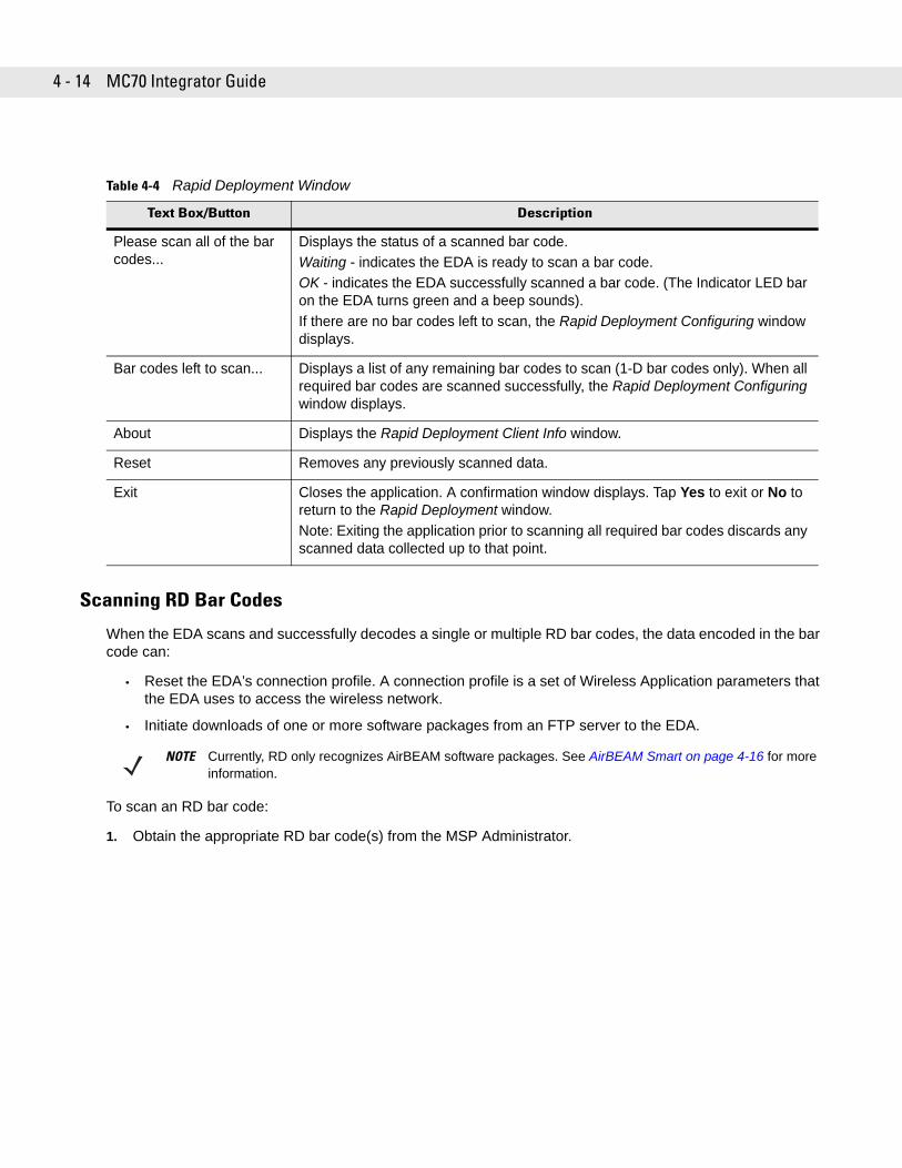
4 - 14 MC70 Integrator Guide
Scanning RD Bar Codes
When the EDA scans and successfully decodes a single or multiple RD bar codes, the data encoded in the bar code can:
• Reset the EDA’s connection profile. A connection profile is a set of Wireless Application parameters that the EDA uses to access the wireless network.
• Initiate downloads of one or more software packages from an FTP server to the EDA.
To scan an RD bar code:
1. Obtain the appropriate RD bar code(s) from the MSP Administrator.
Table 4-4 Rapid Deployment Window
Text Box/Button Description
Please scan all of the bar codes...
Displays the status of a scanned bar code.Waiting - indicates the EDA is ready to scan a bar code.OK - indicates the EDA successfully scanned a bar code. (The Indicator LED bar on the EDA turns green and a beep sounds).If there are no bar codes left to scan, the Rapid Deployment Configuring window displays.
Bar codes left to scan... Displays a list of any remaining bar codes to scan (1-D bar codes only). When all required bar codes are scanned successfully, the Rapid Deployment Configuring window displays.
About Displays the Rapid Deployment Client Info window.
Reset Removes any previously scanned data.
Exit Closes the application. A confirmation window displays. Tap Yes to exit or No to return to the Rapid Deployment window.Note: Exiting the application prior to scanning all required bar codes discards any scanned data collected up to that point.
NOTE Currently, RD only recognizes AirBEAM software packages. See AirBEAM Smart on page 4-16 for more information.
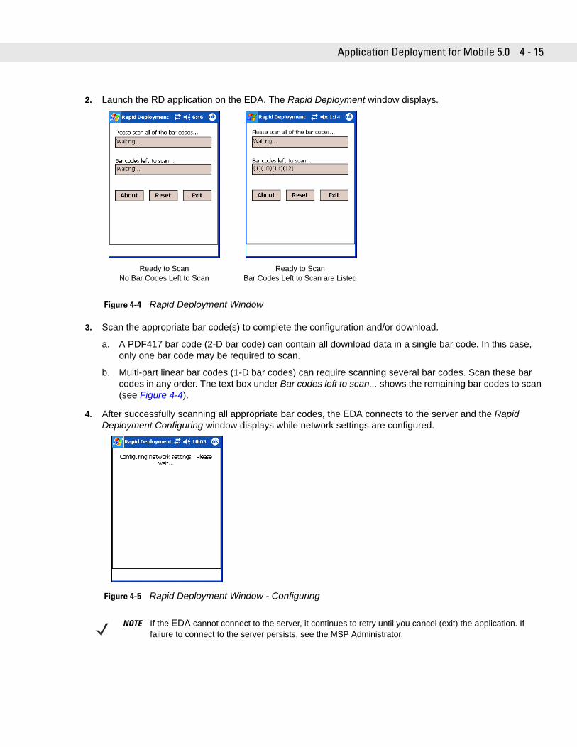
Application Deployment for Mobile 5.0 4 - 15
2. Launch the RD application on the EDA. The Rapid Deployment window displays.
Figure 4-4 Rapid Deployment Window
3. Scan the appropriate bar code(s) to complete the configuration and/or download.
a. A PDF417 bar code (2-D bar code) can contain all download data in a single bar code. In this case, only one bar code may be required to scan.
b. Multi-part linear bar codes (1-D bar codes) can require scanning several bar codes. Scan these bar codes in any order. The text box under Bar codes left to scan... shows the remaining bar codes to scan (see Figure 4-4).
4. After successfully scanning all appropriate bar codes, the EDA connects to the server and the Rapid Deployment Configuring window displays while network settings are configured.
Figure 4-5 Rapid Deployment Window - Configuring
Ready to ScanNo Bar Codes Left to Scan
Ready to ScanBar Codes Left to Scan are Listed
NOTE If the EDA cannot connect to the server, it continues to retry until you cancel (exit) the application. If failure to connect to the server persists, see the MSP Administrator.
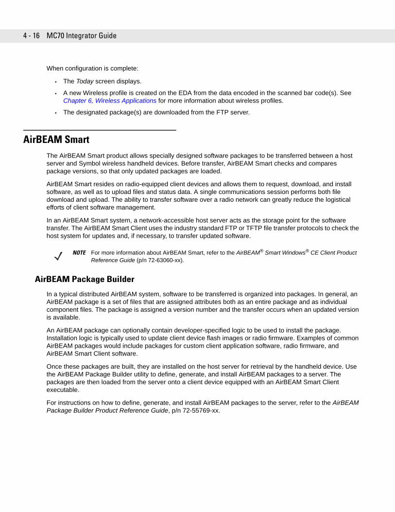
4 - 16 MC70 Integrator Guide
When configuration is complete:
• The Today screen displays.
• A new Wireless profile is created on the EDA from the data encoded in the scanned bar code(s). See Chapter 6, Wireless Applications for more information about wireless profiles.
• The designated package(s) are downloaded from the FTP server.
AirBEAM SmartThe AirBEAM Smart product allows specially designed software packages to be transferred between a host server and Symbol wireless handheld devices. Before transfer, AirBEAM Smart checks and compares package versions, so that only updated packages are loaded.
AirBEAM Smart resides on radio-equipped client devices and allows them to request, download, and install software, as well as to upload files and status data. A single communications session performs both file download and upload. The ability to transfer software over a radio network can greatly reduce the logistical efforts of client software management.
In an AirBEAM Smart system, a network-accessible host server acts as the storage point for the software transfer. The AirBEAM Smart Client uses the industry standard FTP or TFTP file transfer protocols to check the host system for updates and, if necessary, to transfer updated software.
AirBEAM Package Builder
In a typical distributed AirBEAM system, software to be transferred is organized into packages. In general, an AirBEAM package is a set of files that are assigned attributes both as an entire package and as individual component files. The package is assigned a version number and the transfer occurs when an updated version is available.
An AirBEAM package can optionally contain developer-specified logic to be used to install the package. Installation logic is typically used to update client device flash images or radio firmware. Examples of common AirBEAM packages would include packages for custom client application software, radio firmware, and AirBEAM Smart Client software.
Once these packages are built, they are installed on the host server for retrieval by the handheld device. Use the AirBEAM Package Builder utility to define, generate, and install AirBEAM packages to a server. The packages are then loaded from the server onto a client device equipped with an AirBEAM Smart Client executable.
For instructions on how to define, generate, and install AirBEAM packages to the server, refer to the AirBEAM Package Builder Product Reference Guide, p/n 72-55769-xx.
NOTE For more information about AirBEAM Smart, refer to the AirBEAM® Smart Windows® CE Client Product Reference Guide (p/n 72-63060-xx).
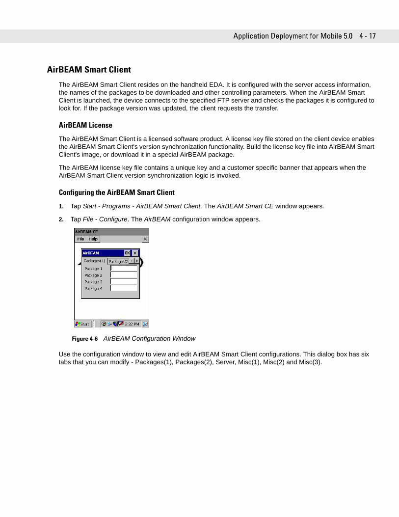
Application Deployment for Mobile 5.0 4 - 17
AirBEAM Smart Client
The AirBEAM Smart Client resides on the handheld EDA. It is configured with the server access information, the names of the packages to be downloaded and other controlling parameters. When the AirBEAM Smart Client is launched, the device connects to the specified FTP server and checks the packages it is configured to look for. If the package version was updated, the client requests the transfer.
AirBEAM License
The AirBEAM Smart Client is a licensed software product. A license key file stored on the client device enables the AirBEAM Smart Client's version synchronization functionality. Build the license key file into AirBEAM Smart Client's image, or download it in a special AirBEAM package.
The AirBEAM license key file contains a unique key and a customer specific banner that appears when the AirBEAM Smart Client version synchronization logic is invoked.
Configuring the AirBEAM Smart Client
1. Tap Start - Programs - AirBEAM Smart Client. The AirBEAM Smart CE window appears.
2. Tap File - Configure. The AirBEAM configuration window appears.
Figure 4-6 AirBEAM Configuration Window
Use the configuration window to view and edit AirBEAM Smart Client configurations. This dialog box has six tabs that you can modify - Packages(1), Packages(2), Server, Misc(1), Misc(2) and Misc(3).
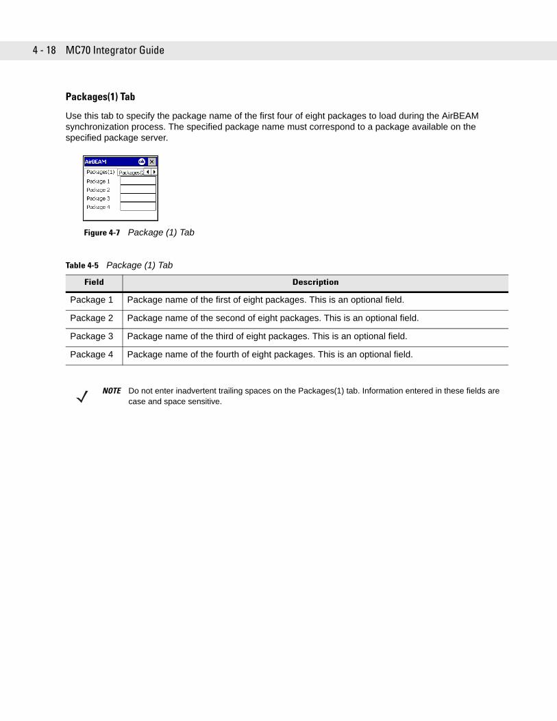
4 - 18 MC70 Integrator Guide
Packages(1) Tab
Use this tab to specify the package name of the first four of eight packages to load during the AirBEAM synchronization process. The specified package name must correspond to a package available on the specified package server.
Figure 4-7 Package (1) Tab
Table 4-5 Package (1) Tab
Field Description
Package 1 Package name of the first of eight packages. This is an optional field.
Package 2 Package name of the second of eight packages. This is an optional field.
Package 3 Package name of the third of eight packages. This is an optional field.
Package 4 Package name of the fourth of eight packages. This is an optional field.
NOTE Do not enter inadvertent trailing spaces on the Packages(1) tab. Information entered in these fields are case and space sensitive.
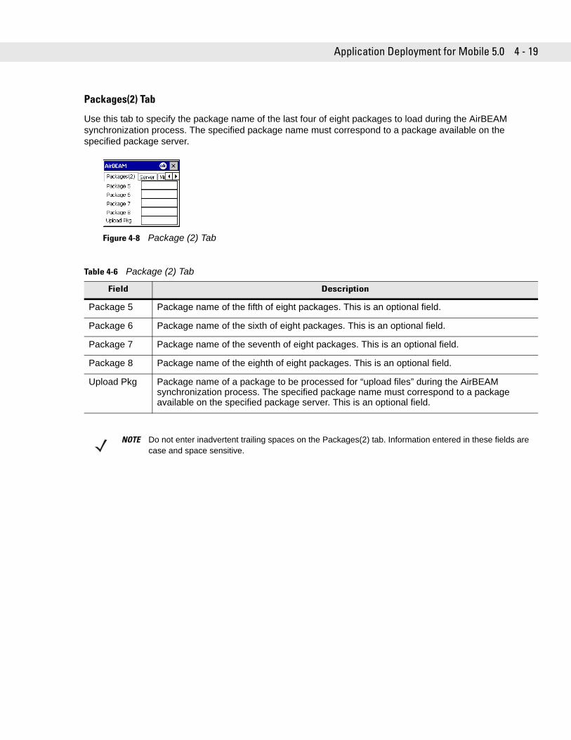
Application Deployment for Mobile 5.0 4 - 19
Packages(2) Tab
Use this tab to specify the package name of the last four of eight packages to load during the AirBEAM synchronization process. The specified package name must correspond to a package available on the specified package server.
Figure 4-8 Package (2) Tab
Table 4-6 Package (2) Tab
Field Description
Package 5 Package name of the fifth of eight packages. This is an optional field.
Package 6 Package name of the sixth of eight packages. This is an optional field.
Package 7 Package name of the seventh of eight packages. This is an optional field.
Package 8 Package name of the eighth of eight packages. This is an optional field.
Upload Pkg Package name of a package to be processed for “upload files” during the AirBEAM synchronization process. The specified package name must correspond to a package available on the specified package server. This is an optional field.
NOTE Do not enter inadvertent trailing spaces on the Packages(2) tab. Information entered in these fields are case and space sensitive.
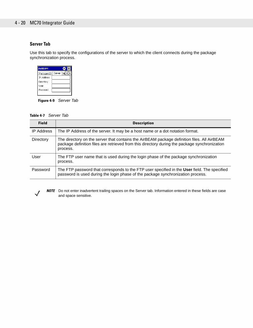
4 - 20 MC70 Integrator Guide
Server Tab
Use this tab to specify the configurations of the server to which the client connects during the package synchronization process.
Figure 4-9 Server Tab
Table 4-7 Server Tab
Field Description
IP Address The IP Address of the server. It may be a host name or a dot notation format.
Directory The directory on the server that contains the AirBEAM package definition files. All AirBEAM package definition files are retrieved from this directory during the package synchronization process.
User The FTP user name that is used during the login phase of the package synchronization process.
Password The FTP password that corresponds to the FTP user specified in the User field. The specified password is used during the login phase of the package synchronization process.
NOTE Do not enter inadvertent trailing spaces on the Server tab. Information entered in these fields are case and space sensitive.
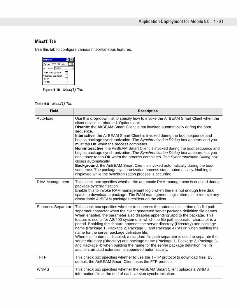
Application Deployment for Mobile 5.0 4 - 21
Misc(1) Tab
Use this tab to configure various miscellaneous features.
Figure 4-10 Misc(1) Tab
Table 4-8 Misc(1) Tab
Field Description
Auto-load Use this drop-down list to specify how to invoke the AirBEAM Smart Client when the client device is rebooted. Options are:Disable: the AirBEAM Smart Client is not invoked automatically during the boot sequence.Interactive: the AirBEAM Smart Client is invoked during the boot sequence and begins package synchronization. The Synchronization Dialog box appears and you must tap OK when the process completes.Non-interactive: the AirBEAM Smart Client is invoked during the boot sequence and begins package synchronization. The Synchronization Dialog box appears, but you don’t have to tap OK when the process completes. The Synchronization Dialog box closes automatically.Background: the AirBEAM Smart Client is invoked automatically during the boot sequence. The package synchronization process starts automatically. Nothing is displayed while the synchronization process is occurring.
RAM Management This check box specifies whether the automatic RAM management is enabled during package synchronization. Enable this to invoke RAM management logic when there is not enough free disk space to download a package. The RAM management logic attempts to remove any discardable AirBEAM packages resident on the client.
Suppress Separator This check box specifies whether to suppress the automatic insertion of a file path separator character when the client generated server package definition file names.When enabled, the parameter also disables appending .apd to the package. This feature is useful for AS/400 systems, in which the file path separator character is a period. Enabling this feature appends the server directory (Directory) and package name (Package 1, Package 2, Package 3, and Package 4) “as is” when building the name for the server package definition file. When this feature is disabled, a standard file path separator is used to separate the server directory (Directory) and package name (Package 1, Package 2, Package 3, and Package 4) when building the name for the server package definition file. In addition, an .apd extension is appended automatically.
TFTP This check box specifies whether to use the TFTP protocol to download files. By default, the AirBEAM Smart Client uses the FTP protocol.
WNMS This check box specifies whether the AirBEAM Smart Client uploads a WNMS information file at the end of each version synchronization.
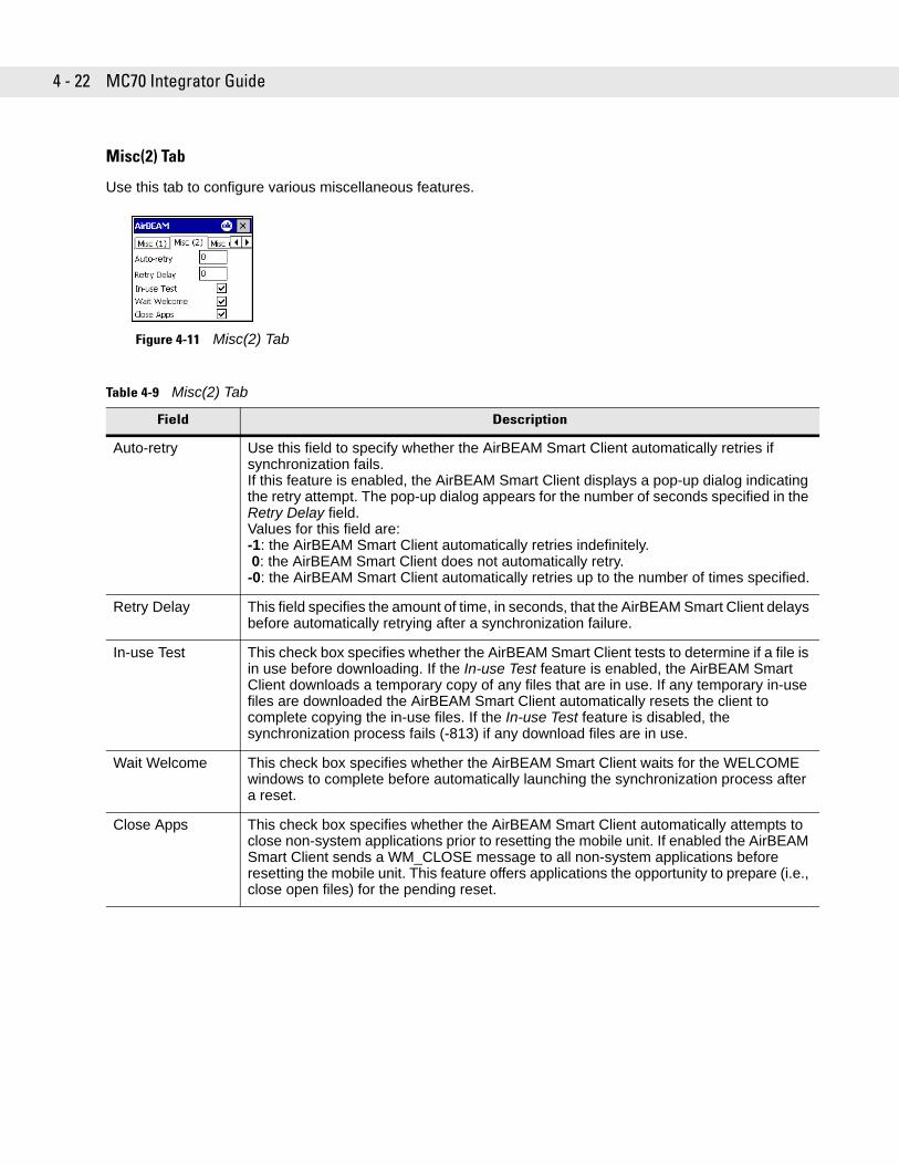
4 - 22 MC70 Integrator Guide
Misc(2) Tab
Use this tab to configure various miscellaneous features.
Figure 4-11 Misc(2) Tab
Table 4-9 Misc(2) Tab
Field Description
Auto-retry Use this field to specify whether the AirBEAM Smart Client automatically retries if synchronization fails. If this feature is enabled, the AirBEAM Smart Client displays a pop-up dialog indicating the retry attempt. The pop-up dialog appears for the number of seconds specified in the Retry Delay field. Values for this field are:-1: the AirBEAM Smart Client automatically retries indefinitely.0: the AirBEAM Smart Client does not automatically retry.-0: the AirBEAM Smart Client automatically retries up to the number of times specified.
Retry Delay This field specifies the amount of time, in seconds, that the AirBEAM Smart Client delays before automatically retrying after a synchronization failure.
In-use Test This check box specifies whether the AirBEAM Smart Client tests to determine if a file is in use before downloading. If the In-use Test feature is enabled, the AirBEAM Smart Client downloads a temporary copy of any files that are in use. If any temporary in-use files are downloaded the AirBEAM Smart Client automatically resets the client to complete copying the in-use files. If the In-use Test feature is disabled, the synchronization process fails (-813) if any download files are in use.
Wait Welcome This check box specifies whether the AirBEAM Smart Client waits for the WELCOME windows to complete before automatically launching the synchronization process after a reset.
Close Apps This check box specifies whether the AirBEAM Smart Client automatically attempts to close non-system applications prior to resetting the mobile unit. If enabled the AirBEAM Smart Client sends a WM_CLOSE message to all non-system applications before resetting the mobile unit. This feature offers applications the opportunity to prepare (i.e., close open files) for the pending reset.
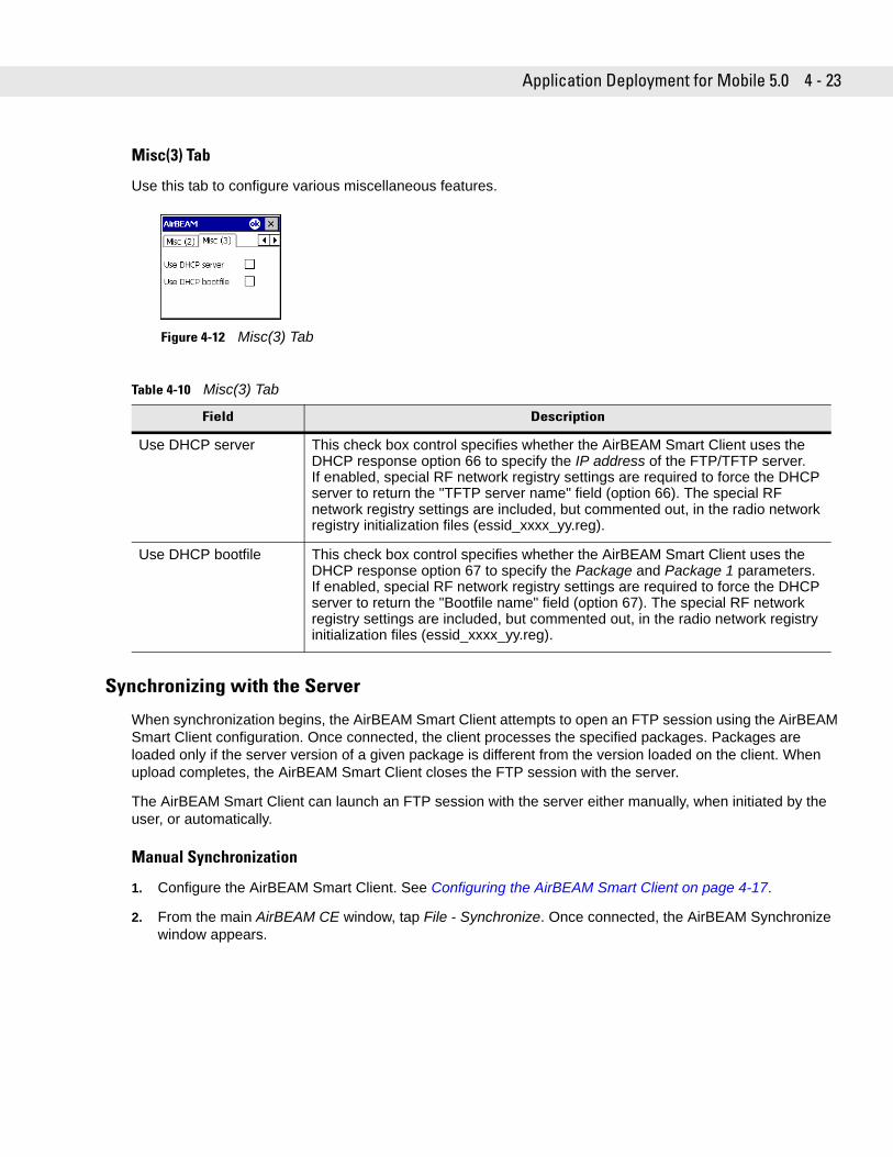
Application Deployment for Mobile 5.0 4 - 23
Misc(3) Tab
Use this tab to configure various miscellaneous features.
Figure 4-12 Misc(3) Tab
Synchronizing with the Server
When synchronization begins, the AirBEAM Smart Client attempts to open an FTP session using the AirBEAM Smart Client configuration. Once connected, the client processes the specified packages. Packages are loaded only if the server version of a given package is different from the version loaded on the client. When upload completes, the AirBEAM Smart Client closes the FTP session with the server.
The AirBEAM Smart Client can launch an FTP session with the server either manually, when initiated by the user, or automatically.
Manual Synchronization
1. Configure the AirBEAM Smart Client. See Configuring the AirBEAM Smart Client on page 4-17.
2. From the main AirBEAM CE window, tap File - Synchronize. Once connected, the AirBEAM Synchronize window appears.
Table 4-10 Misc(3) Tab
Field Description
Use DHCP server This check box control specifies whether the AirBEAM Smart Client uses the DHCP response option 66 to specify the IP address of the FTP/TFTP server.If enabled, special RF network registry settings are required to force the DHCP server to return the "TFTP server name" field (option 66). The special RF network registry settings are included, but commented out, in the radio network registry initialization files (essid_xxxx_yy.reg).
Use DHCP bootfile This check box control specifies whether the AirBEAM Smart Client uses the DHCP response option 67 to specify the Package and Package 1 parameters.If enabled, special RF network registry settings are required to force the DHCP server to return the "Bootfile name" field (option 67). The special RF network registry settings are included, but commented out, in the radio network registry initialization files (essid_xxxx_yy.reg).
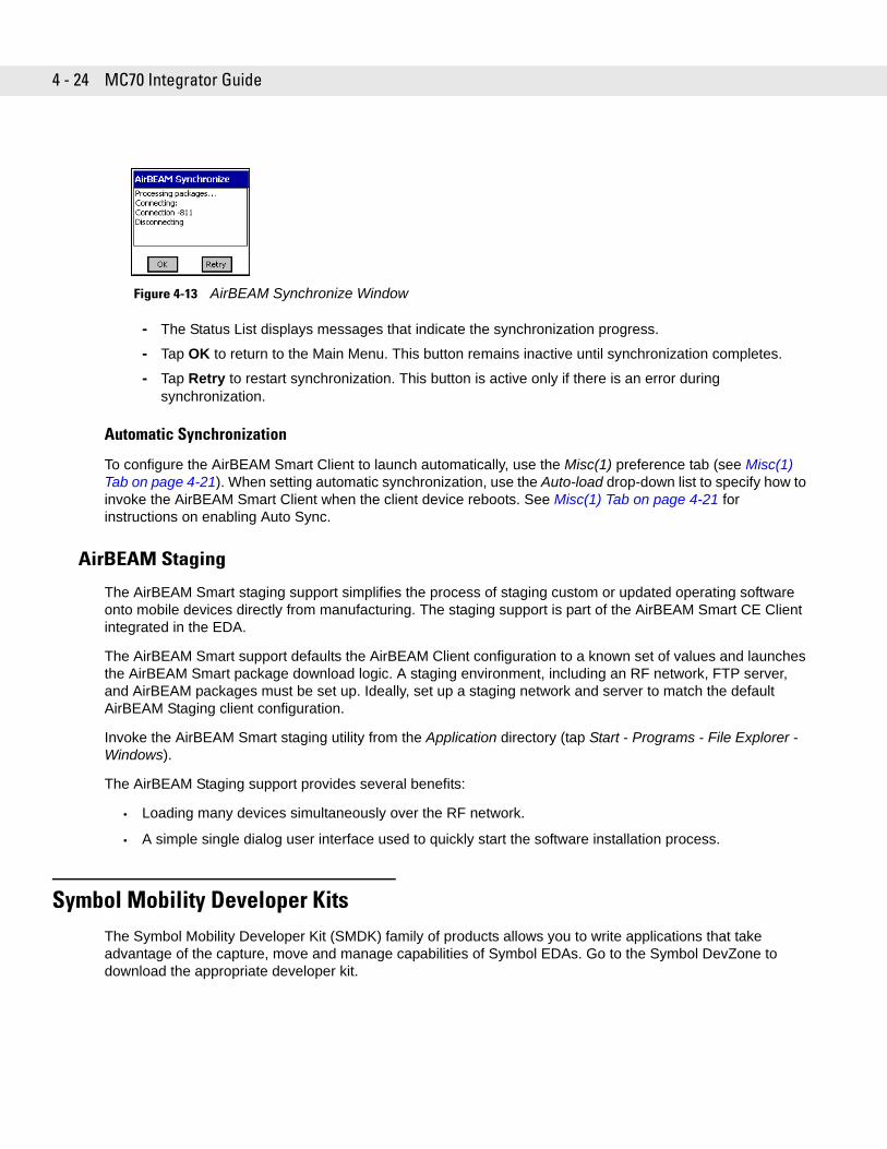
4 - 24 MC70 Integrator Guide
Figure 4-13 AirBEAM Synchronize Window
- The Status List displays messages that indicate the synchronization progress.
- Tap OK to return to the Main Menu. This button remains inactive until synchronization completes.
- Tap Retry to restart synchronization. This button is active only if there is an error during synchronization.
Automatic Synchronization
To configure the AirBEAM Smart Client to launch automatically, use the Misc(1) preference tab (see Misc(1) Tab on page 4-21). When setting automatic synchronization, use the Auto-load drop-down list to specify how to invoke the AirBEAM Smart Client when the client device reboots. See Misc(1) Tab on page 4-21 for instructions on enabling Auto Sync.
AirBEAM Staging
The AirBEAM Smart staging support simplifies the process of staging custom or updated operating software onto mobile devices directly from manufacturing. The staging support is part of the AirBEAM Smart CE Client integrated in the EDA.
The AirBEAM Smart support defaults the AirBEAM Client configuration to a known set of values and launches the AirBEAM Smart package download logic. A staging environment, including an RF network, FTP server, and AirBEAM packages must be set up. Ideally, set up a staging network and server to match the default AirBEAM Staging client configuration.
Invoke the AirBEAM Smart staging utility from the Application directory (tap Start - Programs - File Explorer - Windows).
The AirBEAM Staging support provides several benefits:
• Loading many devices simultaneously over the RF network.
• A simple single dialog user interface used to quickly start the software installation process.
Symbol Mobility Developer KitsThe Symbol Mobility Developer Kit (SMDK) family of products allows you to write applications that take advantage of the capture, move and manage capabilities of Symbol EDAs. Go to the Symbol DevZone to download the appropriate developer kit.
Chapter 5 WAN Configuration
Chapter 5
Chapter 5 WAN ConfigurationIntroductionThis chapter explains how to verify MC70 service on an Enhanced Data rates for Global Evolution (EDGE) wireless network and establish settings. EDGE is also known as Enhanced General Packet Radio Service (EGPRS).
EDGE networks deliver mobile voice and data services, such as Short Message Service (SMS)/Text Messaging, with full roaming capabilities across the world. General Packet Radio Service (GPRS) enabled networks offer Internet-based content and packet-based data services. This enables services such as internet browsing, e-mail on the move, powerful visual communications, multimedia messages, and location-based services.
When using the EDA as a phone, services can include speed dialing, call tracking, voice mail, call forwarding, conference calling, and caller ID, depending on the type of service.
Also use the integrated phone as a modem to connect the EDA to an ISP or work network. The GSM/GPRS enabled EDA can connect to the Internet or work network over GPRS, using Cellular Line, or using the modem specified by the mobile phone service provider.
Quick Startup StepsTo use the EDA for phone and data connections:
1. Install the EDA main battery. See Installing and Removing the Main Battery on page 1-3.
2. Charge the main battery and backup battery. See Charging the Battery on page 1-5.
3. Install the SIM card. See SIM Card on page 1-9.
4. Start the EDA.
5. Ensure network coverage (page 5-2).
6. Configure a GPRS data connection (page 5-3).
NOTE Before using an EDA on a wireless network, first select a provider, establish a voice and data-enabled service plan, and configure the EDA (where applicable). Refer to the MC70 User Guide for information on how to use the phone and services.
NOTE Data connection configuration is pre-packaged with T-Mobile service. Other other service providers may require data connection configuration.
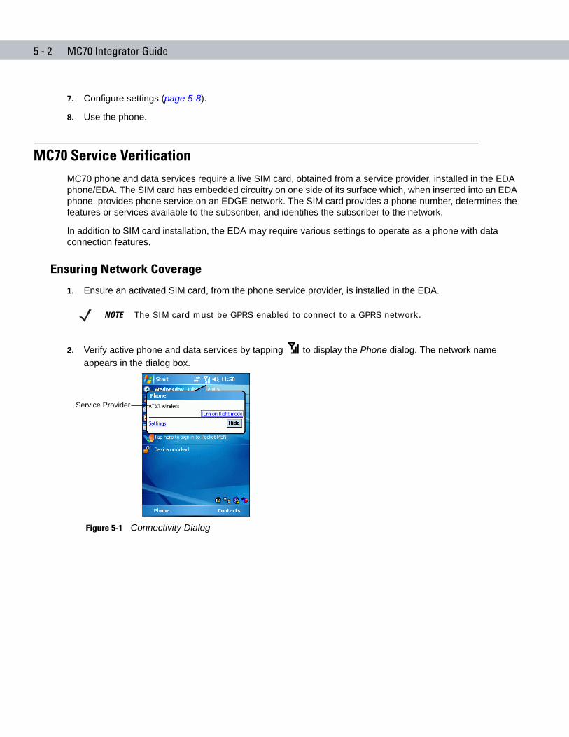
5 - 2 MC70 Integrator Guide
7. Configure settings (page 5-8).
8. Use the phone.
MC70 Service VerificationMC70 phone and data services require a live SIM card, obtained from a service provider, installed in the EDA phone/EDA. The SIM card has embedded circuitry on one side of its surface which, when inserted into an EDA phone, provides phone service on an EDGE network. The SIM card provides a phone number, determines the features or services available to the subscriber, and identifies the subscriber to the network.
In addition to SIM card installation, the EDA may require various settings to operate as a phone with data connection features.
Ensuring Network Coverage
1. Ensure an activated SIM card, from the phone service provider, is installed in the EDA.
2. Verify active phone and data services by tapping to display the Phone dialog. The network name appears in the dialog box.
Figure 5-1 Connectivity Dialog
NOTE The SIM card must be GPRS enabled to connect to a GPRS network.
Service Provider
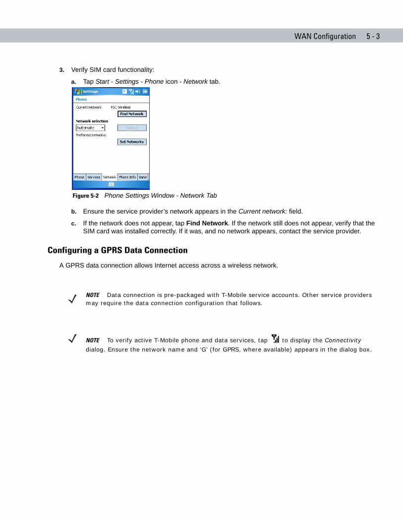
WAN Configuration 5 - 3
3. Verify SIM card functionality:
a. Tap Start - Settings - Phone icon - Network tab.
Figure 5-2 Phone Settings Window - Network Tab
b. Ensure the service provider’s network appears in the Current network: field.
c. If the network does not appear, tap Find Network. If the network still does not appear, verify that the SIM card was installed correctly. If it was, and no network appears, contact the service provider.
Configuring a GPRS Data Connection
A GPRS data connection allows Internet access across a wireless network.
NOTE Data connection is pre-packaged with T-Mobile service accounts. Other service providers may require the data connection configuration that follows.
NOTE To verify active T-Mobile phone and data services, tap to display the Connectivity
dialog. Ensure the network name and ‘G’ (for GPRS, where available) appears in the dialog box.
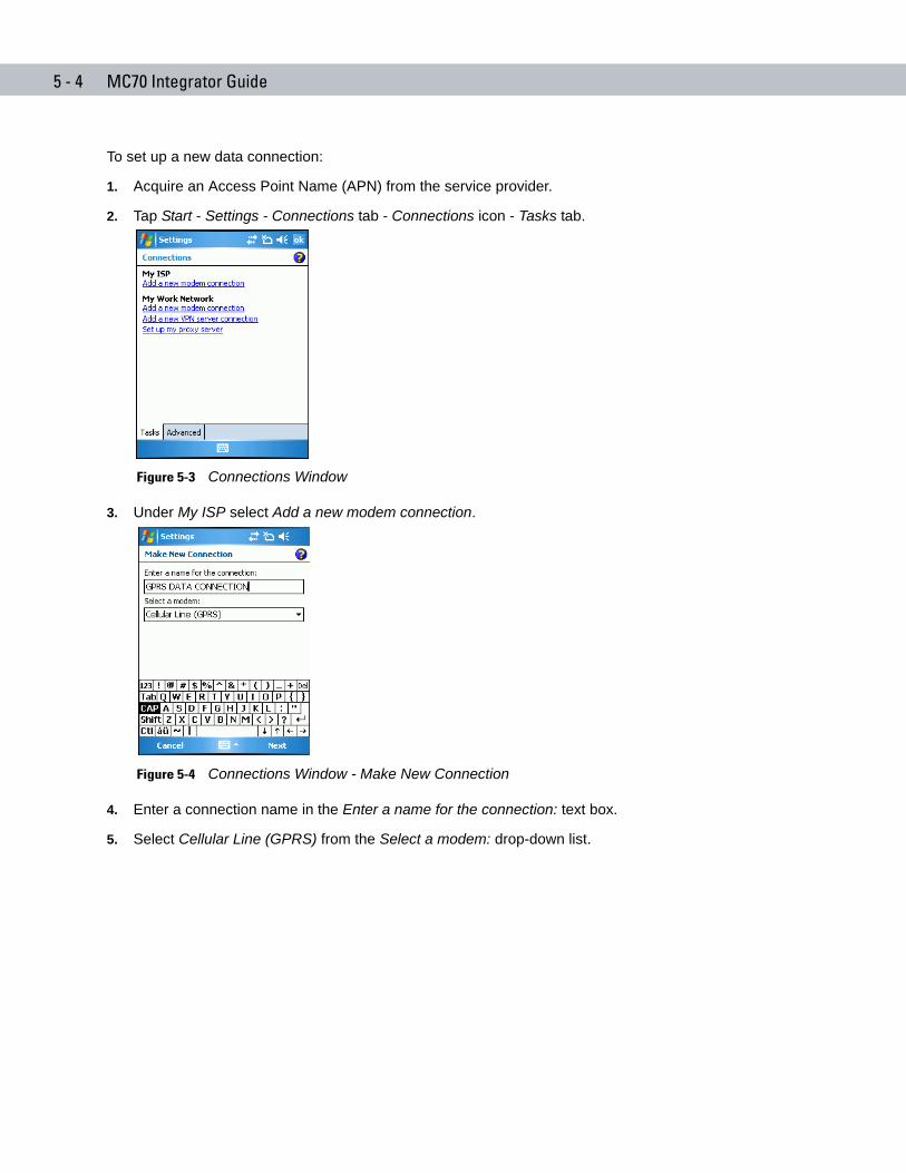
5 - 4 MC70 Integrator Guide
To set up a new data connection:
1. Acquire an Access Point Name (APN) from the service provider.
2. Tap Start - Settings - Connections tab - Connections icon - Tasks tab.
Figure 5-3 Connections Window
3. Under My ISP select Add a new modem connection.
Figure 5-4 Connections Window - Make New Connection
4. Enter a connection name in the Enter a name for the connection: text box.
5. Select Cellular Line (GPRS) from the Select a modem: drop-down list.
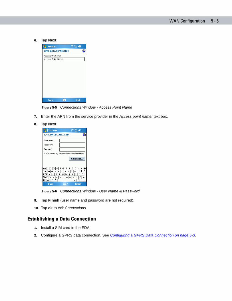
WAN Configuration 5 - 5
6. Tap Next.
Figure 5-5 Connections Window - Access Point Name
7. Enter the APN from the service provider in the Access point name: text box.
8. Tap Next.
Figure 5-6 Connections Window - User Name & Password
9. Tap Finish (user name and password are not required).
10. Tap ok to exit Connections.
Establishing a Data Connection
1. Install a SIM card in the EDA.
2. Configure a GPRS data connection. See Configuring a GPRS Data Connection on page 5-3.
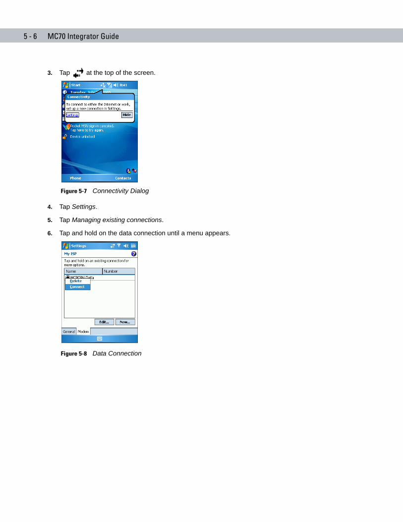
5 - 6 MC70 Integrator Guide
3. Tap at the top of the screen.
Figure 5-7 Connectivity Dialog
4. Tap Settings.
5. Tap Managing existing connections.
6. Tap and hold on the data connection until a menu appears.
Figure 5-8 Data Connection
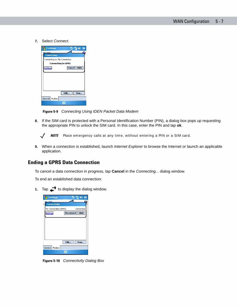
WAN Configuration 5 - 7
7. Select Connect.
Figure 5-9 Connecting Using IDEN Packet Data Modem
8. If the SIM card is protected with a Personal Identification Number (PIN), a dialog box pops up requesting the appropriate PIN to unlock the SIM card. In this case, enter the PIN and tap ok.
9. When a connection is established, launch Internet Explorer to browse the Internet or launch an applicable application.
Ending a GPRS Data Connection
To cancel a data connection in progress, tap Cancel in the Connecting... dialog window.
To end an established data connection:
1. Tap to display the dialog window.
Figure 5-10 Connectivity Dialog Box
NOTE Place emergency calls at any time, without entering a PIN or a SIM card.
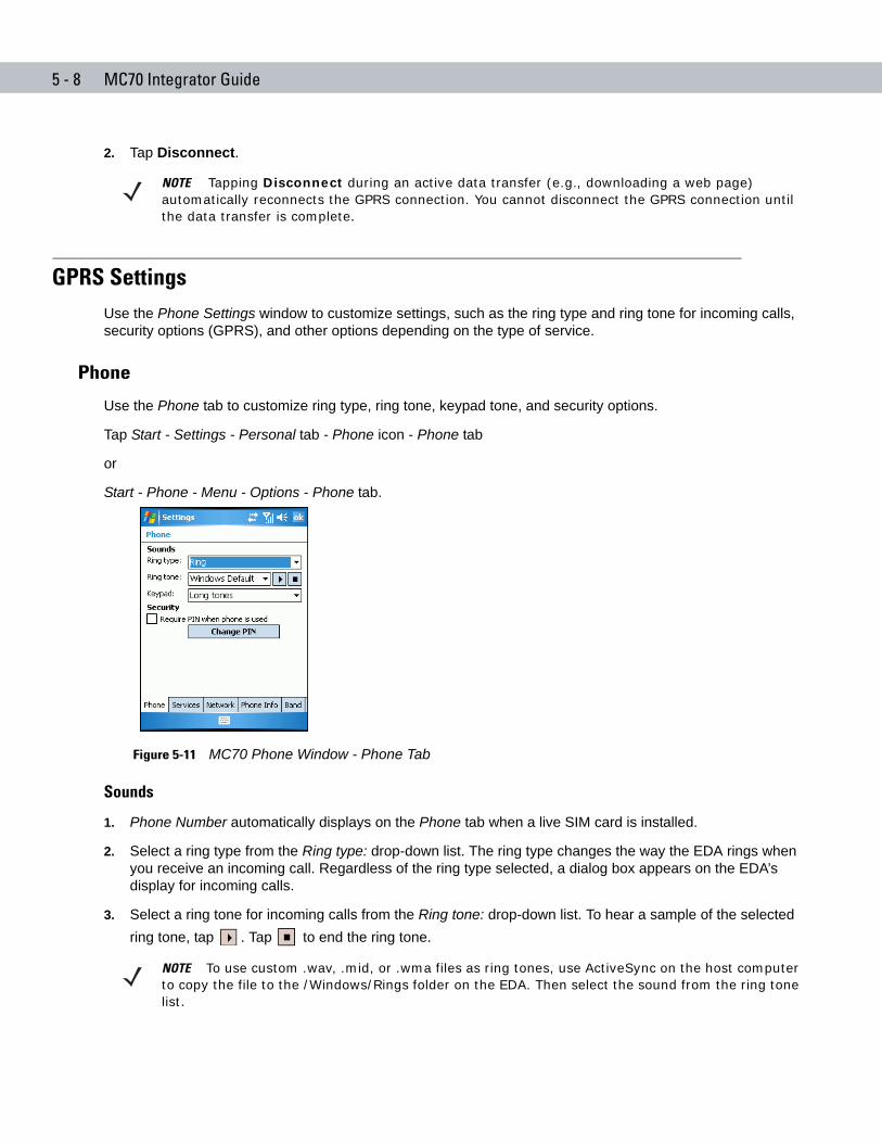
5 - 8 MC70 Integrator Guide
2. Tap Disconnect.
GPRS SettingsUse the Phone Settings window to customize settings, such as the ring type and ring tone for incoming calls, security options (GPRS), and other options depending on the type of service.
Phone
Use the Phone tab to customize ring type, ring tone, keypad tone, and security options.
Tap Start - Settings - Personal tab - Phone icon - Phone tab
or
Start - Phone - Menu - Options - Phone tab.
Figure 5-11 MC70 Phone Window - Phone Tab
Sounds
1. Phone Number automatically displays on the Phone tab when a live SIM card is installed.
2. Select a ring type from the Ring type: drop-down list. The ring type changes the way the EDA rings when you receive an incoming call. Regardless of the ring type selected, a dialog box appears on the EDA’s display for incoming calls.
3. Select a ring tone for incoming calls from the Ring tone: drop-down list. To hear a sample of the selected ring tone, tap . Tap to end the ring tone.
NOTE Tapping Disconnect during an active data transfer (e.g., downloading a web page) automatically reconnects the GPRS connection. You cannot disconnect the GPRS connection until the data transfer is complete.
NOTE To use custom .wav, .mid, or .wma files as ring tones, use ActiveSync on the host computer to copy the file to the /Windows/Rings folder on the EDA. Then select the sound from the ring tone list.
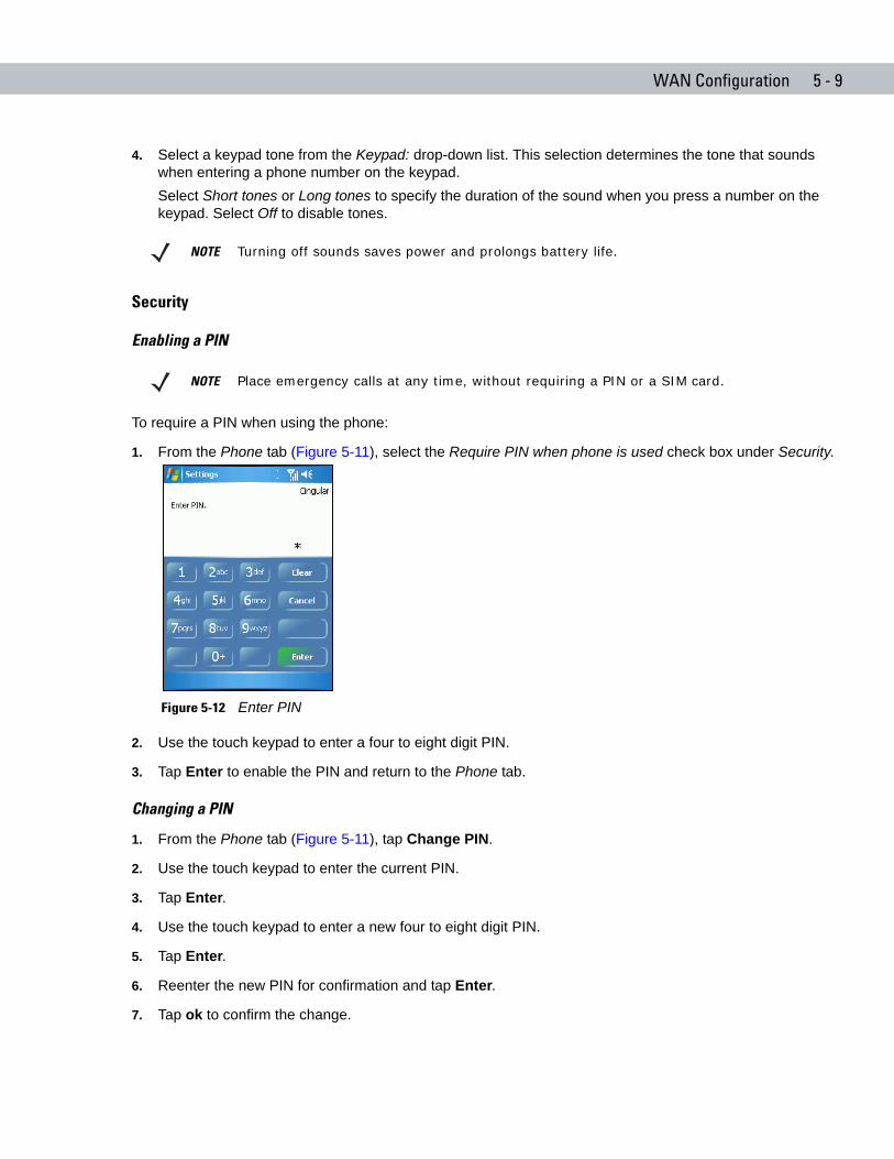
WAN Configuration 5 - 9
4. Select a keypad tone from the Keypad: drop-down list. This selection determines the tone that sounds when entering a phone number on the keypad.Select Short tones or Long tones to specify the duration of the sound when you press a number on the keypad. Select Off to disable tones.
Security
Enabling a PIN
To require a PIN when using the phone:
1. From the Phone tab (Figure 5-11), select the Require PIN when phone is used check box under Security.
Figure 5-12 Enter PIN
2. Use the touch keypad to enter a four to eight digit PIN.
3. Tap Enter to enable the PIN and return to the Phone tab.
Changing a PIN
1. From the Phone tab (Figure 5-11), tap Change PIN.
2. Use the touch keypad to enter the current PIN.
3. Tap Enter.
4. Use the touch keypad to enter a new four to eight digit PIN.
5. Tap Enter.
6. Reenter the new PIN for confirmation and tap Enter.
7. Tap ok to confirm the change.
NOTE Turning off sounds saves power and prolongs battery life.
NOTE Place emergency calls at any time, without requiring a PIN or a SIM card.
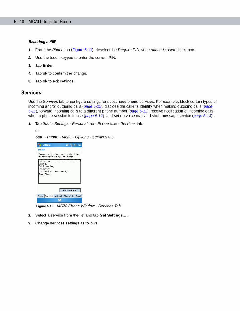
5 - 10 MC70 Integrator Guide
Disabling a PIN
1. From the Phone tab (Figure 5-11), deselect the Require PIN when phone is used check box.
2. Use the touch keypad to enter the current PIN.
3. Tap Enter.
4. Tap ok to confirm the change.
5. Tap ok to exit settings.
Services
Use the Services tab to configure settings for subscribed phone services. For example, block certain types of incoming and/or outgoing calls (page 5-11), disclose the caller’s identity when making outgoing calls (page 5-11), forward incoming calls to a different phone number (page 5-11), receive notification of incoming calls when a phone session is in use (page 5-12), and set up voice mail and short message service (page 5-13).
1. Tap Start - Settings - Personal tab - Phone icon - Services tab.
orStart - Phone - Menu - Options - Services tab.
Figure 5-13 MC70 Phone Window - Services Tab
2. Select a service from the list and tap Get Settings... .
3. Change services settings as follows.
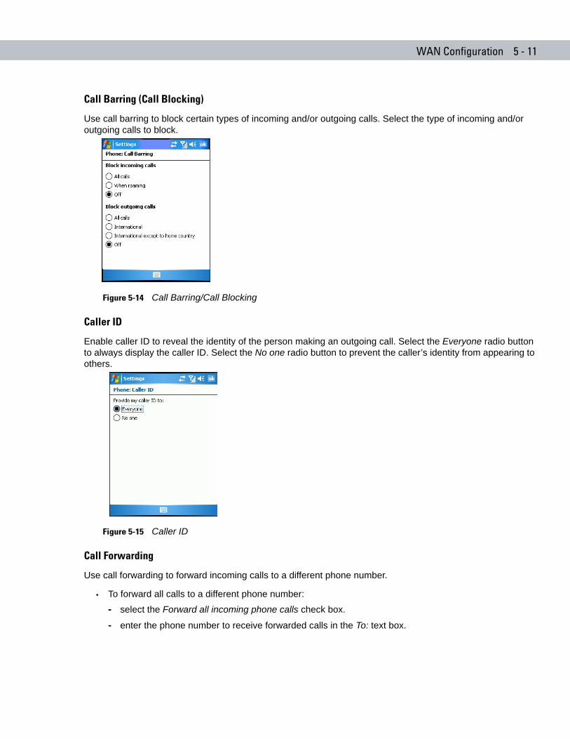
WAN Configuration 5 - 11
Call Barring (Call Blocking)
Use call barring to block certain types of incoming and/or outgoing calls. Select the type of incoming and/or outgoing calls to block.
Figure 5-14 Call Barring/Call Blocking
Caller ID
Enable caller ID to reveal the identity of the person making an outgoing call. Select the Everyone radio button to always display the caller ID. Select the No one radio button to prevent the caller’s identity from appearing to others.
Figure 5-15 Caller ID
Call Forwarding
Use call forwarding to forward incoming calls to a different phone number.
• To forward all calls to a different phone number:
- select the Forward all incoming phone calls check box.
- enter the phone number to receive forwarded calls in the To: text box.
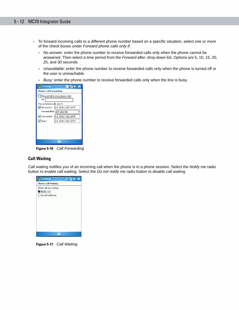
5 - 12 MC70 Integrator Guide
• To forward incoming calls to a different phone number based on a specific situation, select one or more of the check boxes under Forward phone calls only if:
- No answer: enter the phone number to receive forwarded calls only when the phone cannot be answered. Then select a time period from the Forward after: drop-down list. Options are 5, 10, 15, 20, 25, and 30 seconds.
- Unavailable: enter the phone number to receive forwarded calls only when the phone is turned off or the user is unreachable.
- Busy: enter the phone number to receive forwarded calls only when the line is busy.
Figure 5-16 Call Forwarding
Call Waiting
Call waiting notifies you of an incoming call when the phone is in a phone session. Select the Notify me radio button to enable call waiting. Select the Do not notify me radio button to disable call waiting
Figure 5-17 Call Waiting
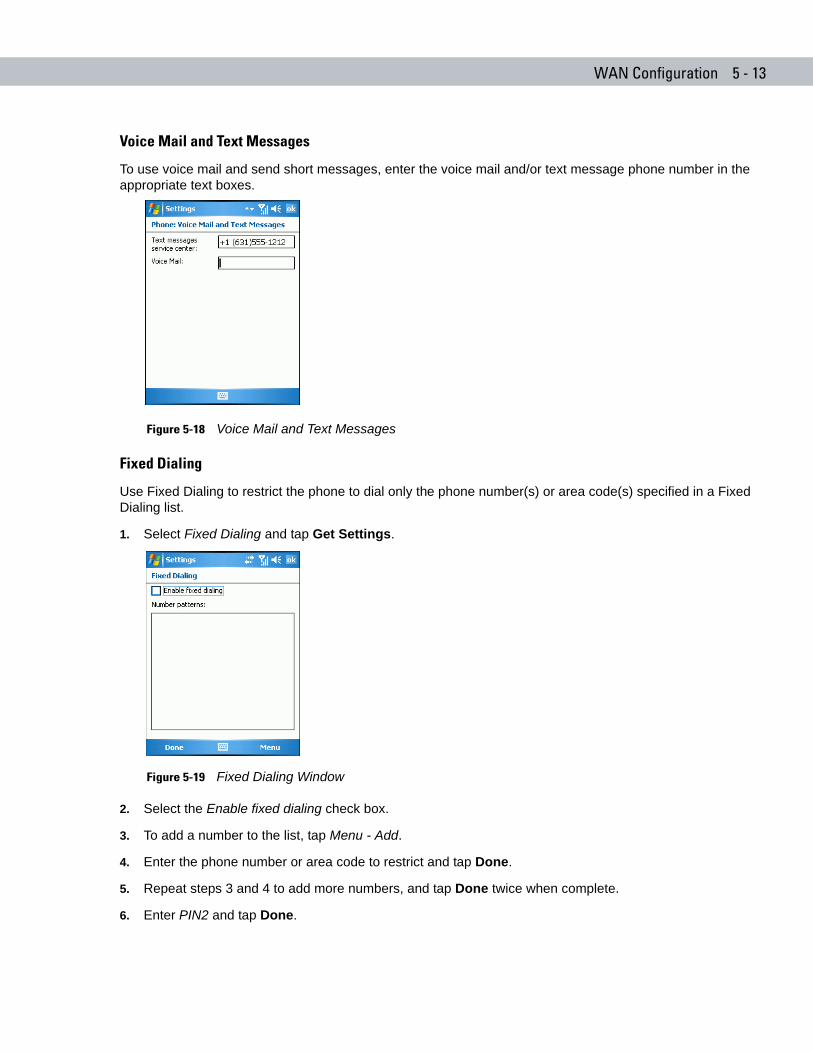
WAN Configuration 5 - 13
Voice Mail and Text Messages
To use voice mail and send short messages, enter the voice mail and/or text message phone number in the appropriate text boxes.
Figure 5-18 Voice Mail and Text Messages
Fixed Dialing
Use Fixed Dialing to restrict the phone to dial only the phone number(s) or area code(s) specified in a Fixed Dialing list.
1. Select Fixed Dialing and tap Get Settings.
Figure 5-19 Fixed Dialing Window
2. Select the Enable fixed dialing check box.
3. To add a number to the list, tap Menu - Add.
4. Enter the phone number or area code to restrict and tap Done.
5. Repeat steps 3 and 4 to add more numbers, and tap Done twice when complete.
6. Enter PIN2 and tap Done.
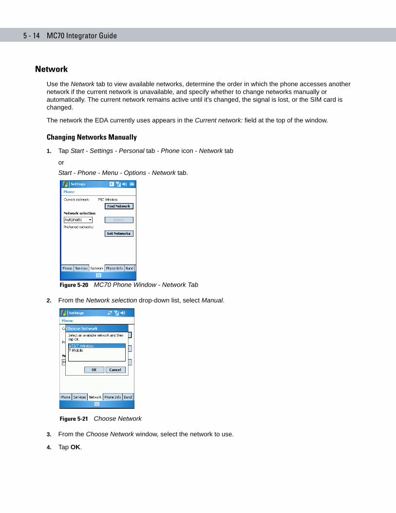
5 - 14 MC70 Integrator Guide
Network
Use the Network tab to view available networks, determine the order in which the phone accesses another network if the current network is unavailable, and specify whether to change networks manually or automatically. The current network remains active until it’s changed, the signal is lost, or the SIM card is changed.
The network the EDA currently uses appears in the Current network: field at the top of the window.
Changing Networks Manually
1. Tap Start - Settings - Personal tab - Phone icon - Network tab
orStart - Phone - Menu - Options - Network tab.
Figure 5-20 MC70 Phone Window - Network Tab
2. From the Network selection drop-down list, select Manual.
Figure 5-21 Choose Network
3. From the Choose Network window, select the network to use.
4. Tap OK.
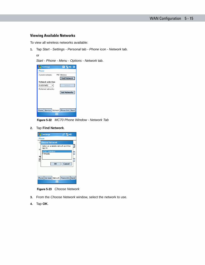
WAN Configuration 5 - 15
Viewing Available Networks
To view all wireless networks available:
1. Tap Start - Settings - Personal tab - Phone icon - Network tab.
orStart - Phone - Menu - Options - Network tab.
Figure 5-22 MC70 Phone Window - Network Tab
2. Tap Find Network.
Figure 5-23 Choose Network
3. From the Choose Network window, select the network to use.
4. Tap OK.
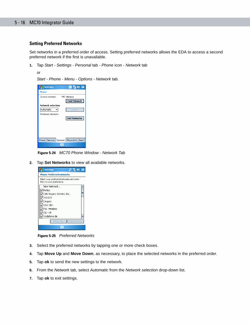
5 - 16 MC70 Integrator Guide
Setting Preferred Networks
Set networks in a preferred order of access. Setting preferred networks allows the EDA to access a second preferred network if the first is unavailable.
1. Tap Start - Settings - Personal tab - Phone icon - Network tab
orStart - Phone - Menu - Options - Network tab.
Figure 5-24 MC70 Phone Window - Network Tab
2. Tap Set Networks to view all available networks.
Figure 5-25 Preferred Networks
3. Select the preferred networks by tapping one or more check boxes.
4. Tap Move Up and Move Down, as necessary, to place the selected networks in the preferred order.
5. Tap ok to send the new settings to the network.
6. From the Network tab, select Automatic from the Network selection drop-down list.
7. Tap ok to exit settings.
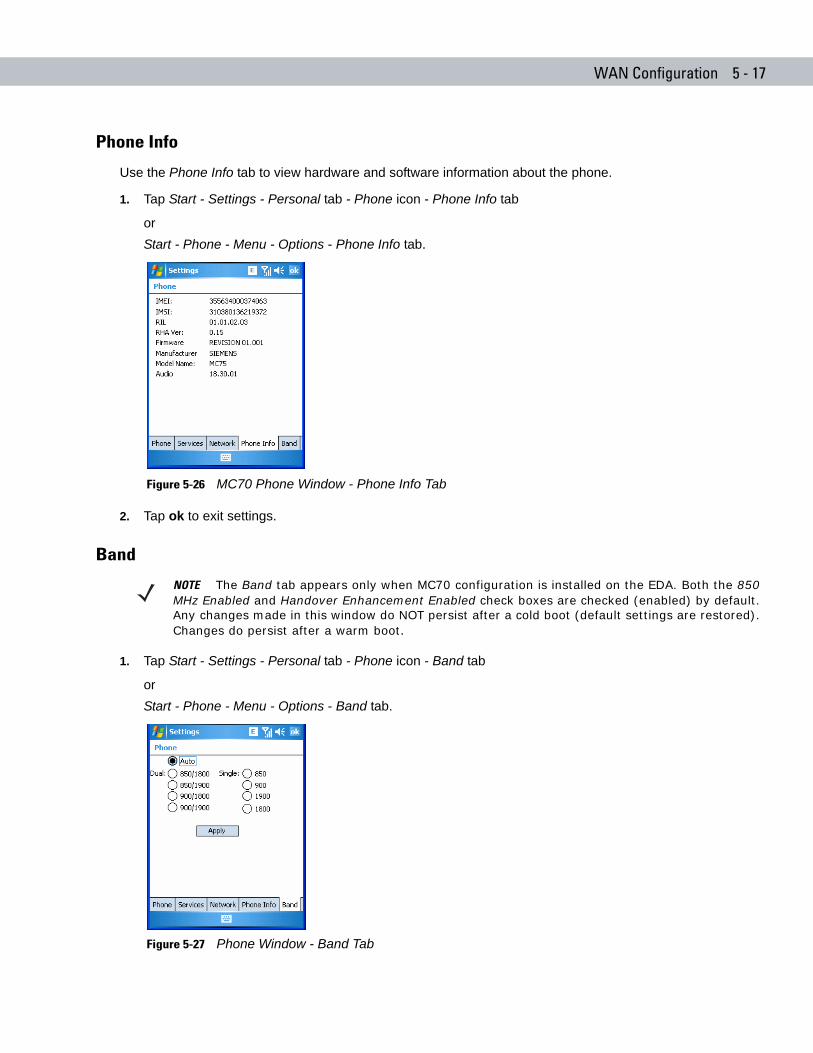
WAN Configuration 5 - 17
Phone Info
Use the Phone Info tab to view hardware and software information about the phone.
1. Tap Start - Settings - Personal tab - Phone icon - Phone Info tab
orStart - Phone - Menu - Options - Phone Info tab.
Figure 5-26 MC70 Phone Window - Phone Info Tab
2. Tap ok to exit settings.
Band
1. Tap Start - Settings - Personal tab - Phone icon - Band tab
orStart - Phone - Menu - Options - Band tab.
Figure 5-27 Phone Window - Band Tab
NOTE The Band tab appears only when MC70 configuration is installed on the EDA. Both the 850 MHz Enabled and Handover Enhancement Enabled check boxes are checked (enabled) by default. Any changes made in this window do NOT persist after a cold boot (default settings are restored). Changes do persist after a warm boot.

5 - 18 MC70 Integrator Guide
2. Select the 850 MHz Enabled check box to enable the radio to hand over in the band of 850MHz (in addition to PCS1900MHz/DCS1800MHz).
3. Disable Handover Enhancement only for some special networks outside of the United States and Europe.
4. Tap ok to exit settings.
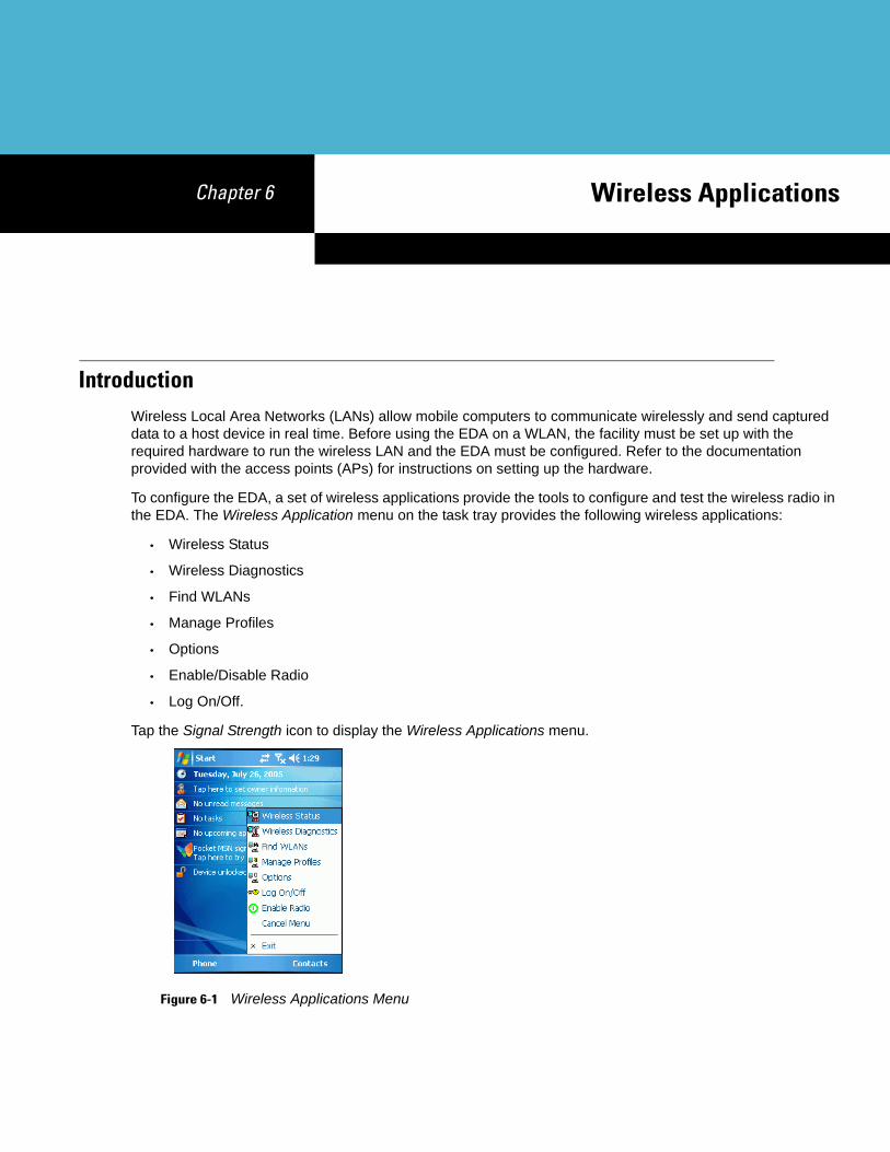
Chapter 6 Wireless Applications
Chapter 6
Chapter 6 Wireless ApplicationsIntroductionWireless Local Area Networks (LANs) allow mobile computers to communicate wirelessly and send captured data to a host device in real time. Before using the EDA on a WLAN, the facility must be set up with the required hardware to run the wireless LAN and the EDA must be configured. Refer to the documentation provided with the access points (APs) for instructions on setting up the hardware.
To configure the EDA, a set of wireless applications provide the tools to configure and test the wireless radio in the EDA. The Wireless Application menu on the task tray provides the following wireless applications:
• Wireless Status
• Wireless Diagnostics
• Find WLANs
• Manage Profiles
• Options
• Enable/Disable Radio
• Log On/Off.
Tap the Signal Strength icon to display the Wireless Applications menu.
Figure 6-1 Wireless Applications Menu
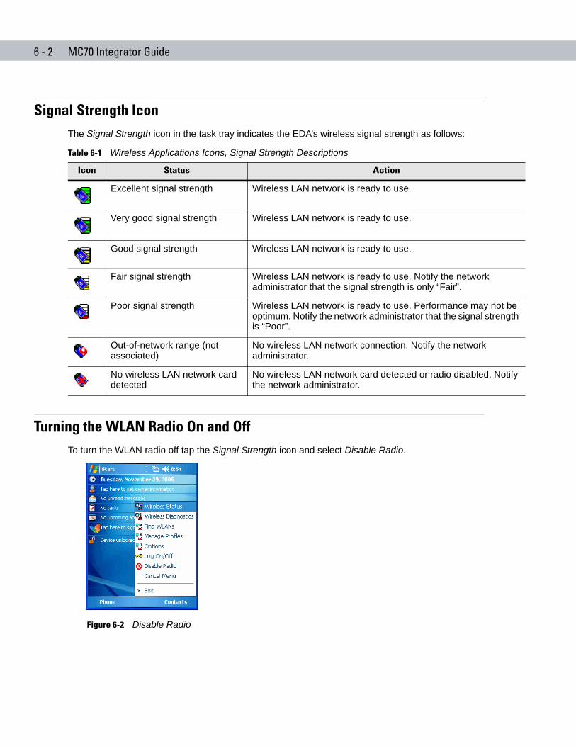
6 - 2 MC70 Integrator Guide
Signal Strength IconThe Signal Strength icon in the task tray indicates the EDA’s wireless signal strength as follows:
Turning the WLAN Radio On and OffTo turn the WLAN radio off tap the Signal Strength icon and select Disable Radio.
Figure 6-2 Disable Radio
Table 6-1 Wireless Applications Icons, Signal Strength Descriptions
Icon Status Action
Excellent signal strength Wireless LAN network is ready to use.
Very good signal strength Wireless LAN network is ready to use.
Good signal strength Wireless LAN network is ready to use.
Fair signal strength Wireless LAN network is ready to use. Notify the network administrator that the signal strength is only “Fair”.
Poor signal strength Wireless LAN network is ready to use. Performance may not be optimum. Notify the network administrator that the signal strength is “Poor”.
Out-of-network range (not associated)
No wireless LAN network connection. Notify the network administrator.
No wireless LAN network card detected
No wireless LAN network card detected or radio disabled. Notify the network administrator.
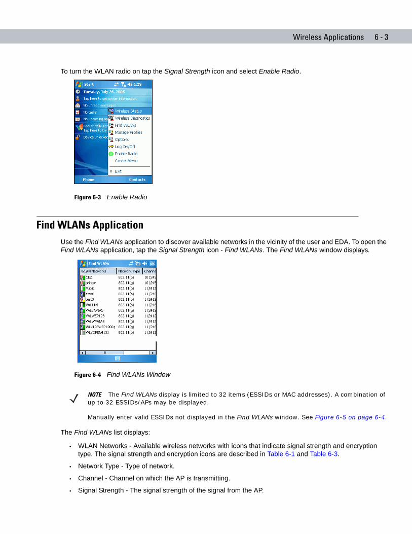
Wireless Applications 6 - 3
To turn the WLAN radio on tap the Signal Strength icon and select Enable Radio.
Figure 6-3 Enable Radio
Find WLANs ApplicationUse the Find WLANs application to discover available networks in the vicinity of the user and EDA. To open the Find WLANs application, tap the Signal Strength icon - Find WLANs. The Find WLANs window displays.
Figure 6-4 Find WLANs Window
The Find WLANs list displays:
• WLAN Networks - Available wireless networks with icons that indicate signal strength and encryption type. The signal strength and encryption icons are described in Table 6-1 and Table 6-3.
• Network Type - Type of network.
• Channel - Channel on which the AP is transmitting.
• Signal Strength - The signal strength of the signal from the AP.
NOTE The Find WLANs display is limited to 32 items (ESSIDs or MAC addresses). A combination of up to 32 ESSIDs/APs may be displayed.
Manually enter valid ESSIDs not displayed in the Find WLANs window. See Figure 6-5 on page 6-4.
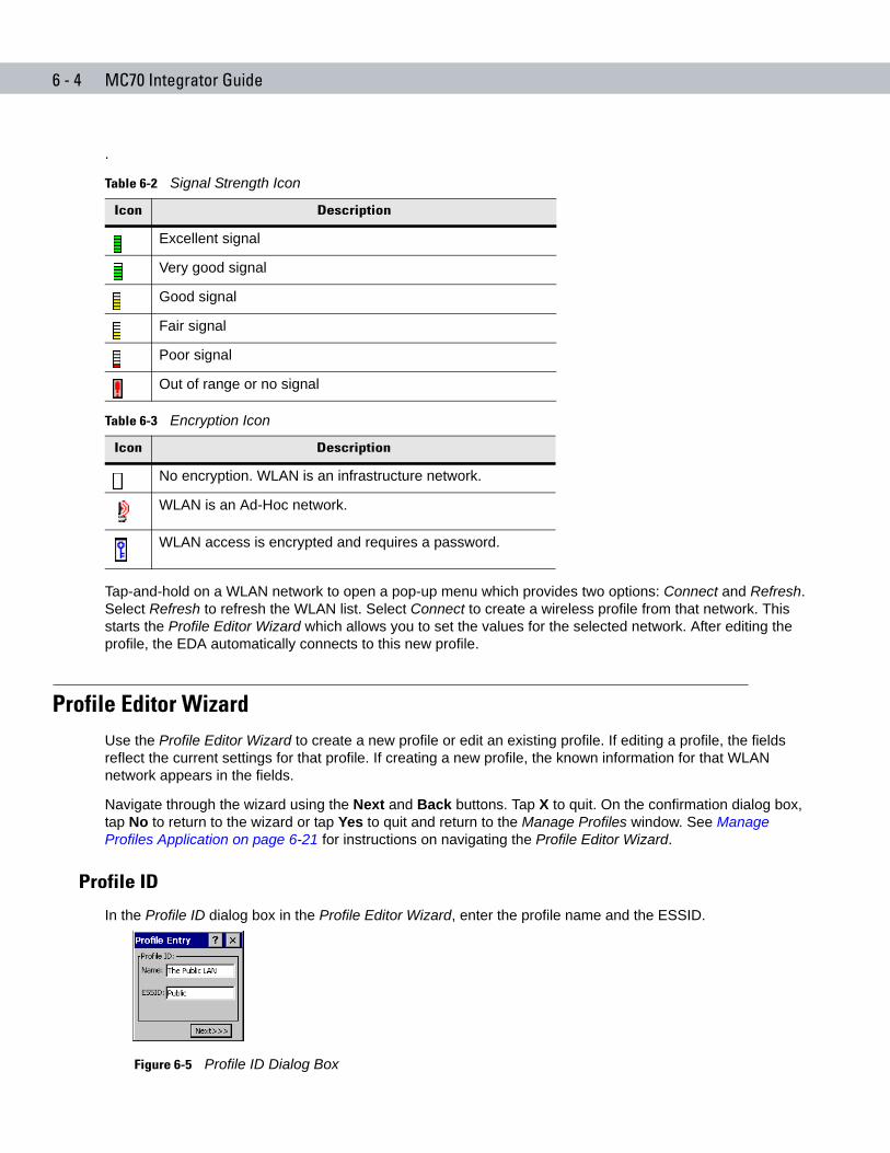
6 - 4 MC70 Integrator Guide
.
Tap-and-hold on a WLAN network to open a pop-up menu which provides two options: Connect and Refresh. Select Refresh to refresh the WLAN list. Select Connect to create a wireless profile from that network. This starts the Profile Editor Wizard which allows you to set the values for the selected network. After editing the profile, the EDA automatically connects to this new profile.
Profile Editor WizardUse the Profile Editor Wizard to create a new profile or edit an existing profile. If editing a profile, the fields reflect the current settings for that profile. If creating a new profile, the known information for that WLAN network appears in the fields.
Navigate through the wizard using the Next and Back buttons. Tap X to quit. On the confirmation dialog box, tap No to return to the wizard or tap Yes to quit and return to the Manage Profiles window. See Manage Profiles Application on page 6-21 for instructions on navigating the Profile Editor Wizard.
Profile ID
In the Profile ID dialog box in the Profile Editor Wizard, enter the profile name and the ESSID.
Figure 6-5 Profile ID Dialog Box
Table 6-2 Signal Strength Icon
Icon Description
Excellent signal
Very good signal
Good signal
Fair signal
Poor signal
Out of range or no signal
Table 6-3 Encryption Icon
Icon Description
No encryption. WLAN is an infrastructure network.
WLAN is an Ad-Hoc network.
WLAN access is encrypted and requires a password.
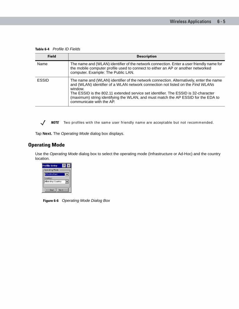
Wireless Applications 6 - 5
Tap Next. The Operating Mode dialog box displays.
Operating Mode
Use the Operating Mode dialog box to select the operating mode (Infrastructure or Ad-Hoc) and the country location.
Figure 6-6 Operating Mode Dialog Box
Table 6-4 Profile ID Fields
Field Description
Name The name and (WLAN) identifier of the network connection. Enter a user friendly name for the mobile computer profile used to connect to either an AP or another networked computer. Example: The Public LAN.
ESSID The name and (WLAN) identifier of the network connection. Alternatively, enter the name and (WLAN) identifier of a WLAN network connection not listed on the Find WLANs window.The ESSID is the 802.11 extended service set identifier. The ESSID is 32-character (maximum) string identifying the WLAN, and must match the AP ESSID for the EDA to communicate with the AP.
NOTE Two profiles with the same user friendly name are acceptable but not recommended.
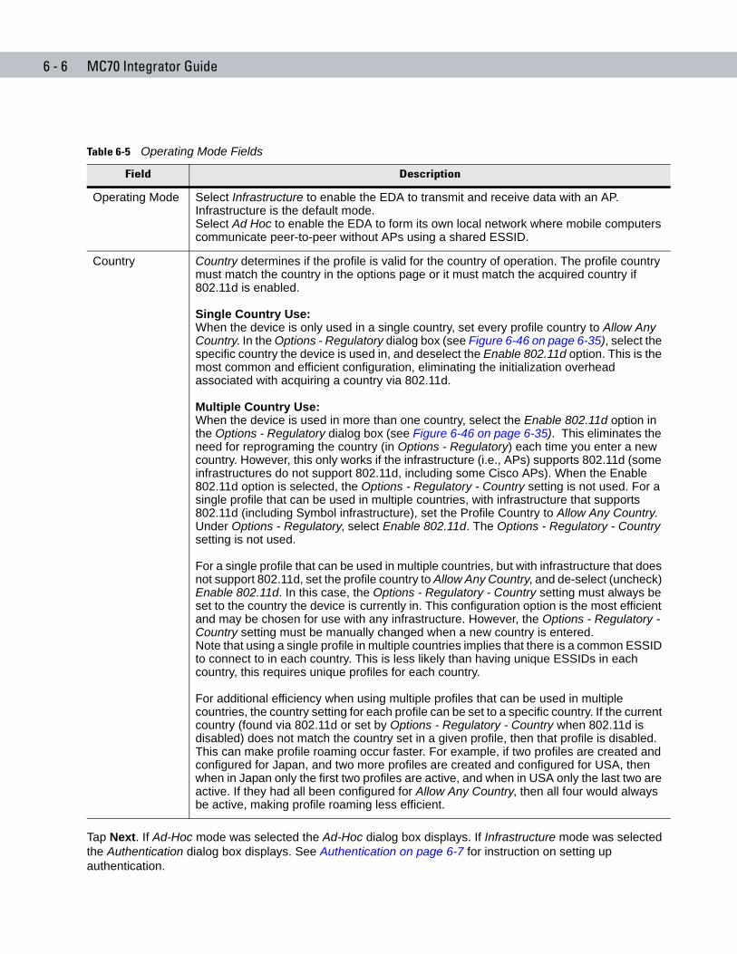
6 - 6 MC70 Integrator Guide
Tap Next. If Ad-Hoc mode was selected the Ad-Hoc dialog box displays. If Infrastructure mode was selected the Authentication dialog box displays. See Authentication on page 6-7 for instruction on setting up authentication.
Table 6-5 Operating Mode Fields
Field Description
Operating Mode Select Infrastructure to enable the EDA to transmit and receive data with an AP. Infrastructure is the default mode.Select Ad Hoc to enable the EDA to form its own local network where mobile computers communicate peer-to-peer without APs using a shared ESSID.
Country Country determines if the profile is valid for the country of operation. The profile country must match the country in the options page or it must match the acquired country if 802.11d is enabled.
Single Country Use:When the device is only used in a single country, set every profile country to Allow Any Country. In the Options - Regulatory dialog box (see Figure 6-46 on page 6-35), select the specific country the device is used in, and deselect the Enable 802.11d option. This is the most common and efficient configuration, eliminating the initialization overhead associated with acquiring a country via 802.11d.
Multiple Country Use:When the device is used in more than one country, select the Enable 802.11d option in the Options - Regulatory dialog box (see Figure 6-46 on page 6-35). This eliminates the need for reprograming the country (in Options - Regulatory) each time you enter a new country. However, this only works if the infrastructure (i.e., APs) supports 802.11d (some infrastructures do not support 802.11d, including some Cisco APs). When the Enable 802.11d option is selected, the Options - Regulatory - Country setting is not used. For a single profile that can be used in multiple countries, with infrastructure that supports 802.11d (including Symbol infrastructure), set the Profile Country to Allow Any Country. Under Options - Regulatory, select Enable 802.11d. The Options - Regulatory - Country setting is not used.
For a single profile that can be used in multiple countries, but with infrastructure that does not support 802.11d, set the profile country to Allow Any Country, and de-select (uncheck) Enable 802.11d. In this case, the Options - Regulatory - Country setting must always be set to the country the device is currently in. This configuration option is the most efficient and may be chosen for use with any infrastructure. However, the Options - Regulatory - Country setting must be manually changed when a new country is entered.Note that using a single profile in multiple countries implies that there is a common ESSID to connect to in each country. This is less likely than having unique ESSIDs in each country, this requires unique profiles for each country.
For additional efficiency when using multiple profiles that can be used in multiple countries, the country setting for each profile can be set to a specific country. If the current country (found via 802.11d or set by Options - Regulatory - Country when 802.11d is disabled) does not match the country set in a given profile, then that profile is disabled. This can make profile roaming occur faster. For example, if two profiles are created and configured for Japan, and two more profiles are created and configured for USA, then when in Japan only the first two profiles are active, and when in USA only the last two are active. If they had all been configured for Allow Any Country, then all four would always be active, making profile roaming less efficient.
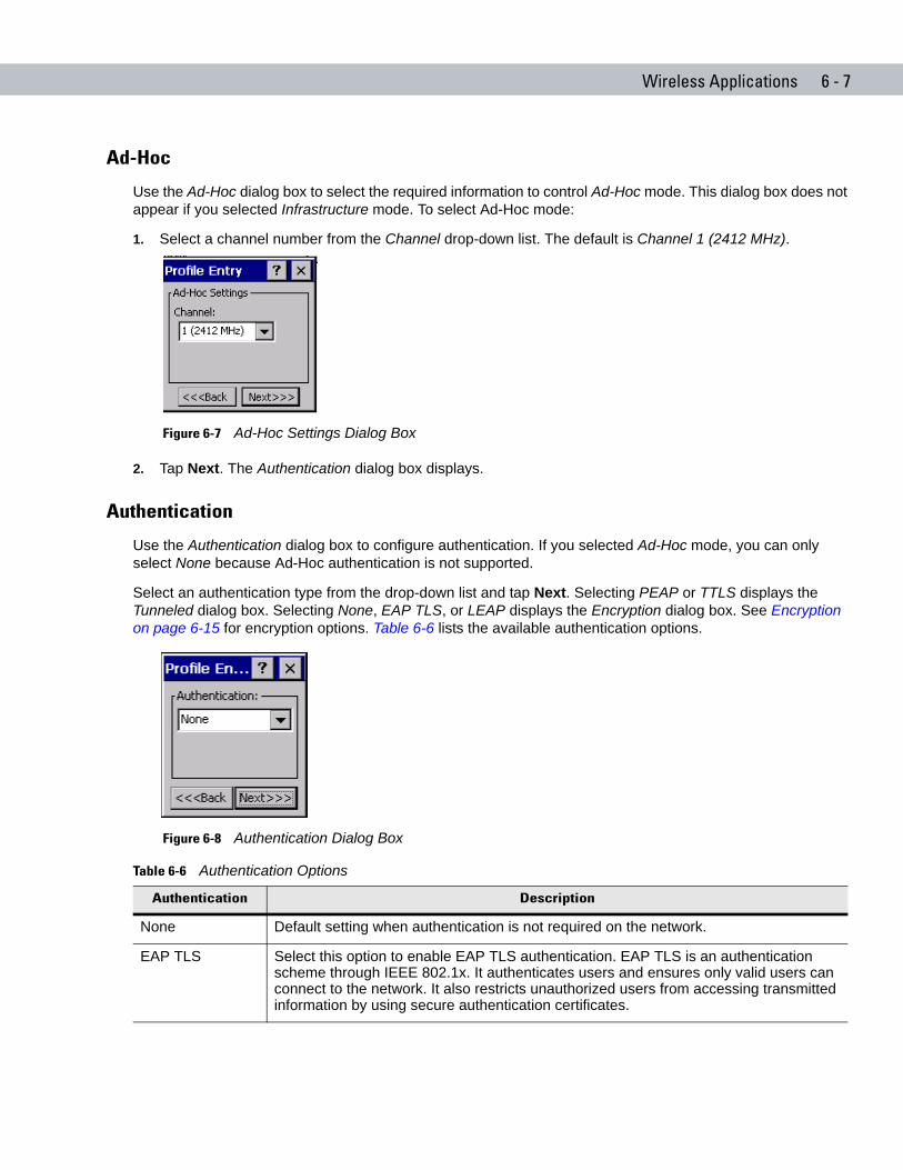
Wireless Applications 6 - 7
Ad-Hoc
Use the Ad-Hoc dialog box to select the required information to control Ad-Hoc mode. This dialog box does not appear if you selected Infrastructure mode. To select Ad-Hoc mode:
1. Select a channel number from the Channel drop-down list. The default is Channel 1 (2412 MHz).
Figure 6-7 Ad-Hoc Settings Dialog Box
2. Tap Next. The Authentication dialog box displays.
Authentication
Use the Authentication dialog box to configure authentication. If you selected Ad-Hoc mode, you can only select None because Ad-Hoc authentication is not supported.
Select an authentication type from the drop-down list and tap Next. Selecting PEAP or TTLS displays the Tunneled dialog box. Selecting None, EAP TLS, or LEAP displays the Encryption dialog box. See Encryption on page 6-15 for encryption options. Table 6-6 lists the available authentication options.
Figure 6-8 Authentication Dialog Box
Table 6-6 Authentication Options
Authentication Description
None Default setting when authentication is not required on the network.
EAP TLS Select this option to enable EAP TLS authentication. EAP TLS is an authentication scheme through IEEE 802.1x. It authenticates users and ensures only valid users can connect to the network. It also restricts unauthorized users from accessing transmitted information by using secure authentication certificates.
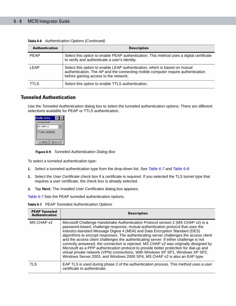
6 - 8 MC70 Integrator Guide
Tunneled Authentication
Use the Tunneled Authentication dialog box to select the tunneled authentication options. There are different selections available for PEAP or TTLS authentication.
Figure 6-9 Tunneled Authentication Dialog Box
To select a tunneled authentication type:
1. Select a tunneled authentication type from the drop-down list. See Table 6-7 and Table 6-8.
2. Select the User Certificate check box if a certificate is required. If you selected the TLS tunnel type that requires a user certificate, the check box is already selected.
3. Tap Next. The Installed User Certificates dialog box appears.
Table 6-7 lists the PEAP tunneled authentication options.
PEAP Select this option to enable PEAP authentication. This method uses a digital certificate to verify and authenticate a user's identity.
LEAP Select this option to enable LEAP authentication, which is based on mutual authentication. The AP and the connecting mobile computer require authentication before gaining access to the network.
TTLS Select this option to enable TTLS authentication.
Table 6-6 Authentication Options (Continued)
Authentication Description
Table 6-7 PEAP Tunneled Authentication Options
PEAP Tunneled Authentication Description
MS CHAP v2 Microsoft Challenge Handshake Authentication Protocol version 2 (MS CHAP v2) is a password-based, challenge-response, mutual authentication protocol that uses the industry-standard Message Digest 4 (MD4) and Data Encryption Standard (DES) algorithms to encrypt responses. The authenticating server challenges the access client and the access client challenges the authenticating server. If either challenge is not correctly answered, the connection is rejected. MS CHAP v2 was originally designed by Microsoft as a PPP authentication protocol to provide better protection for dial-up and virtual private network (VPN) connections. With Windows XP SP1, Windows XP SP2, Windows Server 2003, and Windows 2000 SP4, MS CHAP v2 is also an EAP type.
TLS EAP TLS is used during phase 2 of the authentication process. This method uses a user certificate to authenticate.
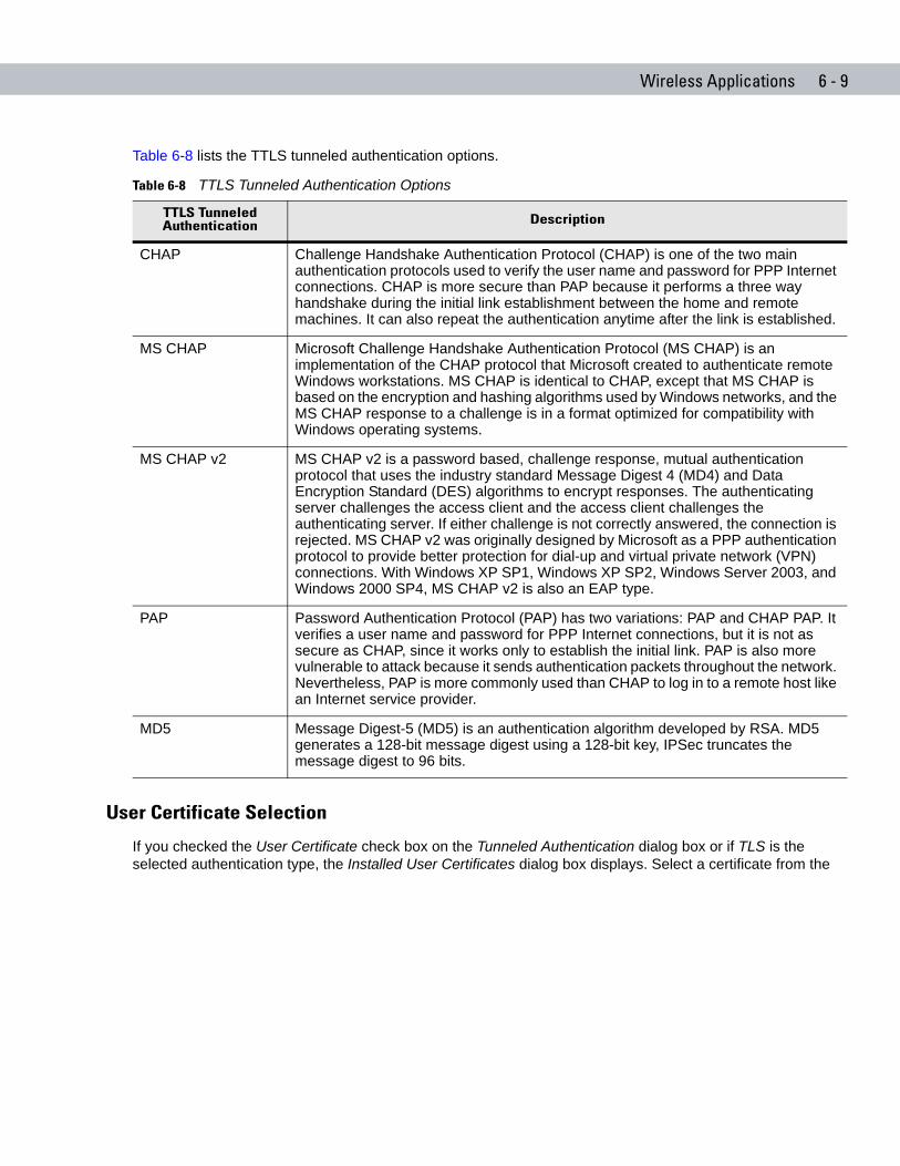
Wireless Applications 6 - 9
Table 6-8 lists the TTLS tunneled authentication options.
User Certificate Selection
If you checked the User Certificate check box on the Tunneled Authentication dialog box or if TLS is the selected authentication type, the Installed User Certificates dialog box displays. Select a certificate from the
Table 6-8 TTLS Tunneled Authentication Options
TTLS Tunneled Authentication Description
CHAP Challenge Handshake Authentication Protocol (CHAP) is one of the two main authentication protocols used to verify the user name and password for PPP Internet connections. CHAP is more secure than PAP because it performs a three way handshake during the initial link establishment between the home and remote machines. It can also repeat the authentication anytime after the link is established.
MS CHAP Microsoft Challenge Handshake Authentication Protocol (MS CHAP) is an implementation of the CHAP protocol that Microsoft created to authenticate remote Windows workstations. MS CHAP is identical to CHAP, except that MS CHAP is based on the encryption and hashing algorithms used by Windows networks, and the MS CHAP response to a challenge is in a format optimized for compatibility with Windows operating systems.
MS CHAP v2 MS CHAP v2 is a password based, challenge response, mutual authentication protocol that uses the industry standard Message Digest 4 (MD4) and Data Encryption Standard (DES) algorithms to encrypt responses. The authenticating server challenges the access client and the access client challenges the authenticating server. If either challenge is not correctly answered, the connection is rejected. MS CHAP v2 was originally designed by Microsoft as a PPP authentication protocol to provide better protection for dial-up and virtual private network (VPN) connections. With Windows XP SP1, Windows XP SP2, Windows Server 2003, and Windows 2000 SP4, MS CHAP v2 is also an EAP type.
PAP Password Authentication Protocol (PAP) has two variations: PAP and CHAP PAP. It verifies a user name and password for PPP Internet connections, but it is not as secure as CHAP, since it works only to establish the initial link. PAP is also more vulnerable to attack because it sends authentication packets throughout the network. Nevertheless, PAP is more commonly used than CHAP to log in to a remote host like an Internet service provider.
MD5 Message Digest-5 (MD5) is an authentication algorithm developed by RSA. MD5 generates a 128-bit message digest using a 128-bit key, IPSec truncates the message digest to 96 bits.
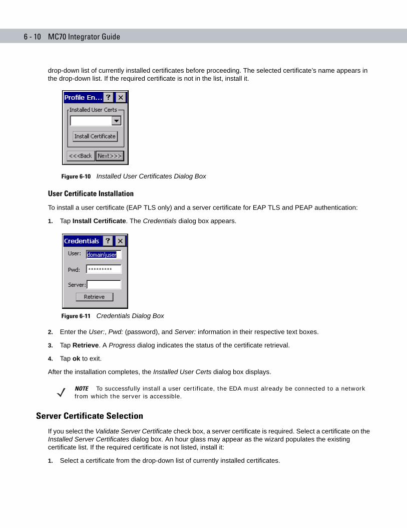
6 - 10 MC70 Integrator Guide
drop-down list of currently installed certificates before proceeding. The selected certificate’s name appears in the drop-down list. If the required certificate is not in the list, install it.
Figure 6-10 Installed User Certificates Dialog Box
User Certificate Installation
To install a user certificate (EAP TLS only) and a server certificate for EAP TLS and PEAP authentication:
1. Tap Install Certificate. The Credentials dialog box appears.
Figure 6-11 Credentials Dialog Box
2. Enter the User:, Pwd: (password), and Server: information in their respective text boxes.
3. Tap Retrieve. A Progress dialog indicates the status of the certificate retrieval.
4. Tap ok to exit.
After the installation completes, the Installed User Certs dialog box displays.
Server Certificate Selection
If you select the Validate Server Certificate check box, a server certificate is required. Select a certificate on the Installed Server Certificates dialog box. An hour glass may appear as the wizard populates the existing certificate list. If the required certificate is not listed, install it:
1. Select a certificate from the drop-down list of currently installed certificates.
*********
NOTE To successfully install a user certificate, the EDA must already be connected to a network from which the server is accessible.
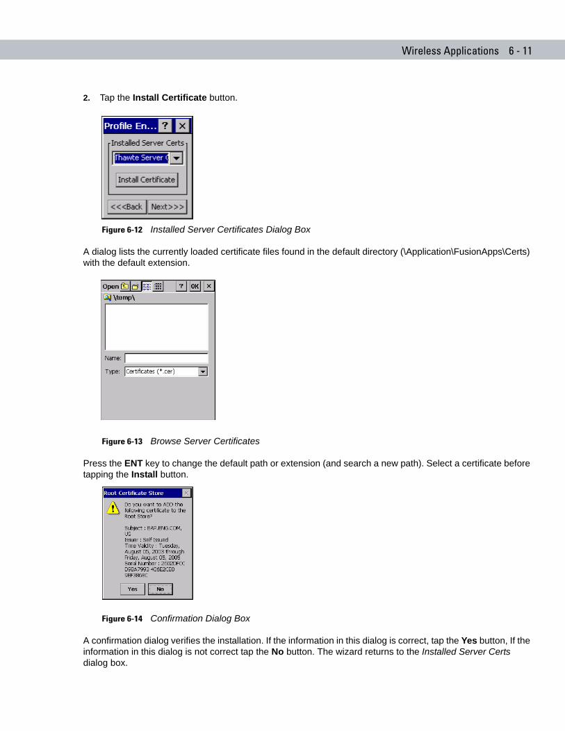
Wireless Applications 6 - 11
2. Tap the Install Certificate button.
Figure 6-12 Installed Server Certificates Dialog Box
A dialog lists the currently loaded certificate files found in the default directory (\Application\FusionApps\Certs) with the default extension.
Figure 6-13 Browse Server Certificates
Press the ENT key to change the default path or extension (and search a new path). Select a certificate before tapping the Install button.
Figure 6-14 Confirmation Dialog Box
A confirmation dialog verifies the installation. If the information in this dialog is correct, tap the Yes button, If the information in this dialog is not correct tap the No button. The wizard returns to the Installed Server Certs dialog box.
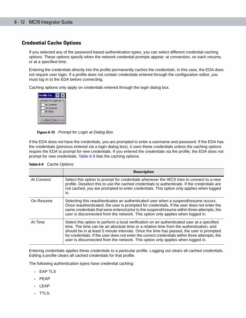
6 - 12 MC70 Integrator Guide
Credential Cache Options
If you selected any of the password-based authentication types, you can select different credential caching options. These options specify when the network credential prompts appear: at connection, on each resume, or at a specified time.
Entering the credentials directly into the profile permanently caches the credentials. In this case, the EDA does not require user login. If a profile does not contain credentials entered through the configuration editor, you must log in to the EDA before connecting.
Caching options only apply on credentials entered through the login dialog box.
Figure 6-15 Prompt for Login at Dialog Box
If the EDA does not have the credentials, you are prompted to enter a username and password. If the EDA has the credentials (previous entered via a login dialog box), it uses these credentials unless the caching options require the EDA to prompt for new credentials. If you entered the credentials via the profile, the EDA does not prompt for new credentials. Table 6-9 lists the caching options.
Entering credentials applies these credentials to a particular profile. Logging out clears all cached credentials. Editing a profile clears all cached credentials for that profile.
The following authentication types have credential caching:
• EAP TLS
• PEAP
• LEAP
• TTLS.
Table 6-9 Cache Options
Description
At Connect Select this option to prompt for credentials whenever the WCS tries to connect to a new profile. Deselect this to use the cached credentials to authenticate. If the credentials are not cached, you are prompted to enter credentials. This option only applies when logged in.
On Resume Selecting this reauthenticates an authenticated user when a suspend/resume occurs. Once reauthenticated, the user is prompted for credentials. If the user does not enter the same credentials that were entered prior to the suspend/resume within three attempts, the user is disconnected from the network. This option only applies when logged in.
At Time Select this option to perform a local verification on an authenticated user at a specified time. The time can be an absolute time or a relative time from the authentication, and should be in at least 5 minute intervals. Once the time has passed, the user is prompted for credentials. If the user does not enter the correct credentials within three attempts, the user is disconnected from the network. This option only applies when logged in.
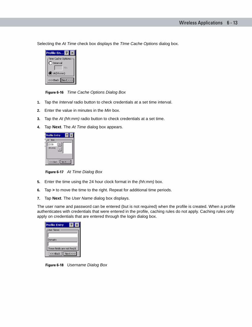
Wireless Applications 6 - 13
Selecting the At Time check box displays the TIme Cache Options dialog box.
Figure 6-16 Time Cache Options Dialog Box
1. Tap the Interval radio button to check credentials at a set time interval.
2. Enter the value in minutes in the Min box.
3. Tap the At (hh:mm) radio button to check credentials at a set time.
4. Tap Next. The At Time dialog box appears.
Figure 6-17 At Time Dialog Box
5. Enter the time using the 24 hour clock format in the (hh:mm) box.
6. Tap > to move the time to the right. Repeat for additional time periods.
7. Tap Next. The User Name dialog box displays.
The user name and password can be entered (but is not required) when the profile is created. When a profile authenticates with credentials that were entered in the profile, caching rules do not apply. Caching rules only apply on credentials that are entered through the login dialog box.
Figure 6-18 Username Dialog Box
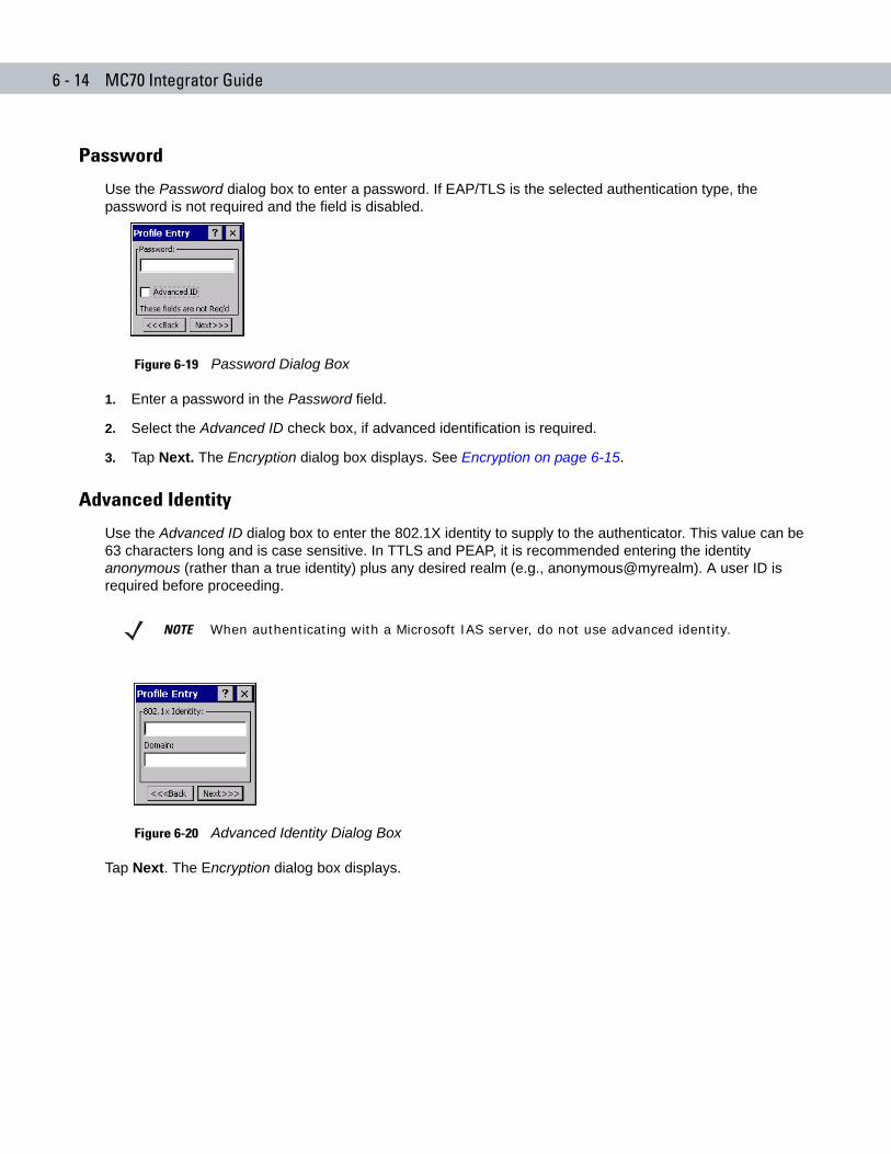
6 - 14 MC70 Integrator Guide
Password
Use the Password dialog box to enter a password. If EAP/TLS is the selected authentication type, the password is not required and the field is disabled.
Figure 6-19 Password Dialog Box
1. Enter a password in the Password field.
2. Select the Advanced ID check box, if advanced identification is required.
3. Tap Next. The Encryption dialog box displays. See Encryption on page 6-15.
Advanced Identity
Use the Advanced ID dialog box to enter the 802.1X identity to supply to the authenticator. This value can be 63 characters long and is case sensitive. In TTLS and PEAP, it is recommended entering the identity anonymous (rather than a true identity) plus any desired realm (e.g., anonymous@myrealm). A user ID is required before proceeding.
Figure 6-20 Advanced Identity Dialog Box
Tap Next. The Encryption dialog box displays.
NOTE When authenticating with a Microsoft IAS server, do not use advanced identity.
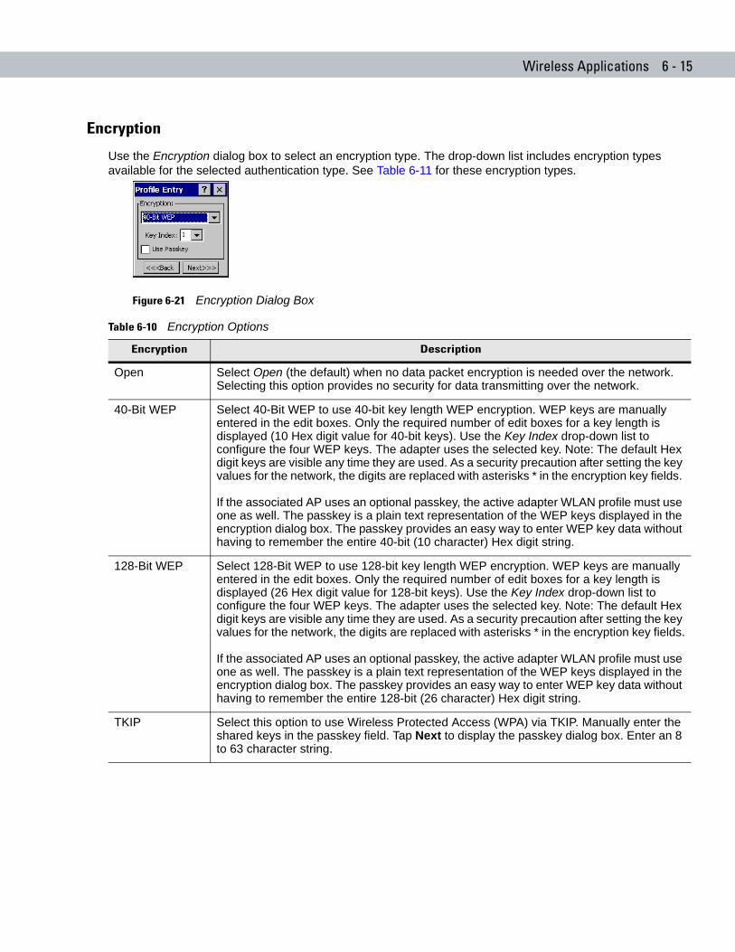
Wireless Applications 6 - 15
Encryption
Use the Encryption dialog box to select an encryption type. The drop-down list includes encryption types available for the selected authentication type. See Table 6-11 for these encryption types.
Figure 6-21 Encryption Dialog Box
Table 6-10 Encryption Options
Encryption Description
Open Select Open (the default) when no data packet encryption is needed over the network. Selecting this option provides no security for data transmitting over the network.
40-Bit WEP Select 40-Bit WEP to use 40-bit key length WEP encryption. WEP keys are manually entered in the edit boxes. Only the required number of edit boxes for a key length is displayed (10 Hex digit value for 40-bit keys). Use the Key Index drop-down list to configure the four WEP keys. The adapter uses the selected key. Note: The default Hex digit keys are visible any time they are used. As a security precaution after setting the key values for the network, the digits are replaced with asterisks * in the encryption key fields.
If the associated AP uses an optional passkey, the active adapter WLAN profile must use one as well. The passkey is a plain text representation of the WEP keys displayed in the encryption dialog box. The passkey provides an easy way to enter WEP key data without having to remember the entire 40-bit (10 character) Hex digit string.
128-Bit WEP Select 128-Bit WEP to use 128-bit key length WEP encryption. WEP keys are manually entered in the edit boxes. Only the required number of edit boxes for a key length is displayed (26 Hex digit value for 128-bit keys). Use the Key Index drop-down list to configure the four WEP keys. The adapter uses the selected key. Note: The default Hex digit keys are visible any time they are used. As a security precaution after setting the key values for the network, the digits are replaced with asterisks * in the encryption key fields.
If the associated AP uses an optional passkey, the active adapter WLAN profile must use one as well. The passkey is a plain text representation of the WEP keys displayed in the encryption dialog box. The passkey provides an easy way to enter WEP key data without having to remember the entire 128-bit (26 character) Hex digit string.
TKIP Select this option to use Wireless Protected Access (WPA) via TKIP. Manually enter the shared keys in the passkey field. Tap Next to display the passkey dialog box. Enter an 8 to 63 character string.
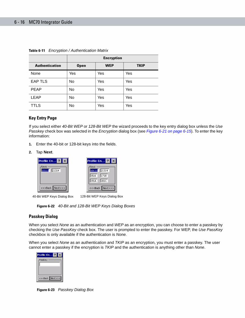
6 - 16 MC70 Integrator Guide
Key Entry Page
If you select either 40-Bit WEP or 128-Bit WEP the wizard proceeds to the key entry dialog box unless the Use Passkey check box was selected in the Encryption dialog box (see Figure 6-21 on page 6-15). To enter the key information:
1. Enter the 40-bit or 128-bit keys into the fields.
2. Tap Next.
Figure 6-22 40-Bit and 128-Bit WEP Keys Dialog Boxes
Passkey Dialog
When you select None as an authentication and WEP as an encryption, you can choose to enter a passkey by checking the Use PassKey check box. The user is prompted to enter the passkey. For WEP, the Use PassKey checkbox is only available if the authentication is None.
When you select None as an authentication and TKIP as an encryption, you must enter a passkey. The user cannot enter a passkey if the encryption is TKIP and the authentication is anything other than None.
Figure 6-23 Passkey Dialog Box
Table 6-11 Encryption / Authentication Matrix
Encryption
Authentication Open WEP TKIP
None Yes Yes Yes
EAP TLS No Yes Yes
PEAP No Yes Yes
LEAP No Yes Yes
TTLS No Yes Yes
40-Bit WEP Keys Dialog Box 128-Bit WEP Keys Dialog Box
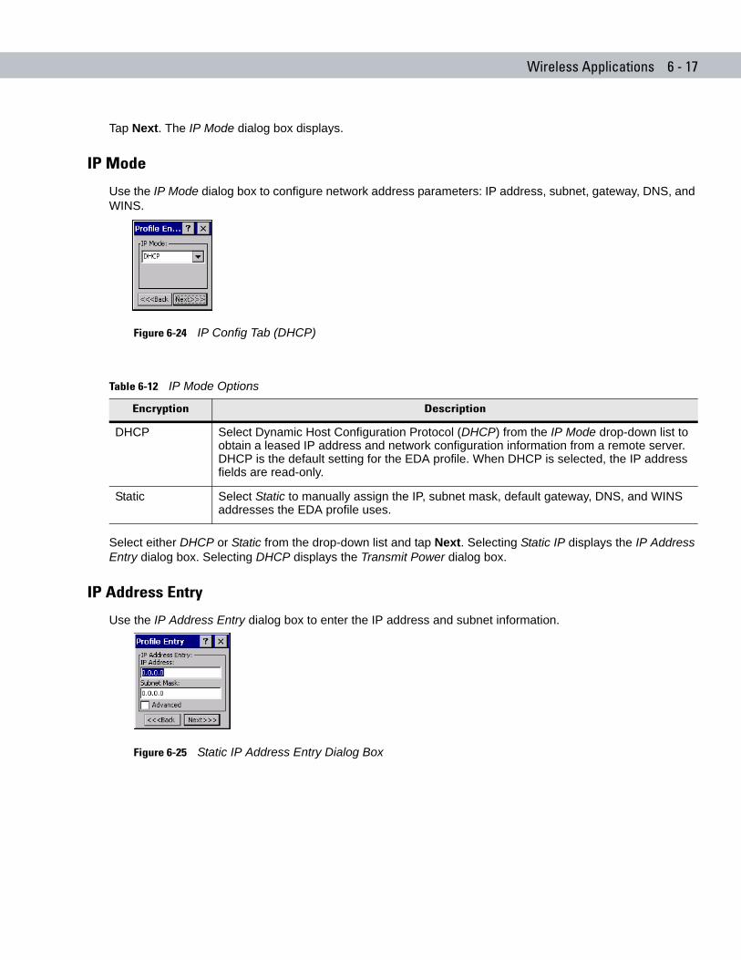
Wireless Applications 6 - 17
Tap Next. The IP Mode dialog box displays.
IP Mode
Use the IP Mode dialog box to configure network address parameters: IP address, subnet, gateway, DNS, and WINS.
Figure 6-24 IP Config Tab (DHCP)
Select either DHCP or Static from the drop-down list and tap Next. Selecting Static IP displays the IP Address Entry dialog box. Selecting DHCP displays the Transmit Power dialog box.
IP Address Entry
Use the IP Address Entry dialog box to enter the IP address and subnet information.
Figure 6-25 Static IP Address Entry Dialog Box
Table 6-12 IP Mode Options
Encryption Description
DHCP Select Dynamic Host Configuration Protocol (DHCP) from the IP Mode drop-down list to obtain a leased IP address and network configuration information from a remote server. DHCP is the default setting for the EDA profile. When DHCP is selected, the IP address fields are read-only.
Static Select Static to manually assign the IP, subnet mask, default gateway, DNS, and WINS addresses the EDA profile uses.
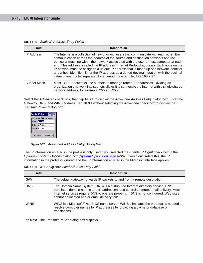
6 - 18 MC70 Integrator Guide
Select the Advanced check box, then tap NEXT to display the Advanced Address Entry dialog box. Enter the Gateway, DNS, and WINS address. Tap NEXT without selecting the Advanced check box to display the Transmit Power dialog box.
Figure 6-26 Advanced Address Entry Dialog Box
The IP information entered in the profile is only used if you selected the Enable IP Mgmt check box in the Options - System Options dialog box (System Options on page 6-36). If you didn’t select this, the IP information in the profile is ignored and the IP information entered in the Microsoft interface applies.
Tap Next. The Transmit Power dialog box displays.
Table 6-13 Static IP Address Entry Fields
Field Description
IP Address The Internet is a collection of networks with users that communicate with each other. Each communication carries the address of the source and destination networks and the particular machine within the network associated with the user or host computer at each end. This address is called the IP address (Internet Protocol address). Each node on the IP network must be assigned a unique IP address that is made up of a network identifier and a host identifier. Enter the IP address as a dotted-decimal notation with the decimal value of each octet separated by a period, for example, 192.168.7.27.
Subnet Mask Most TCP/IP networks use subnets to manage routed IP addresses. Dividing an organization's network into subnets allows it to connect to the Internet with a single shared network address, for example, 255.255.255.0.
Table 6-14 IP Config Advanced Address Entry Fields
Field Description
G/W The default gateway forwards IP packets to and from a remote destination.
DNS The Domain Name System (DNS) is a distributed Internet directory service. DNS translates domain names and IP addresses, and controls Internet email delivery. Most Internet services require DNS to operate properly. If DNS is not configured, Web sites cannot be located and/or email delivery fails.
WINS WINS is a Microsoft® Net BIOS name server. WINS eliminates the broadcasts needed to resolve computer names to IP addresses by providing a cache or database of translations.
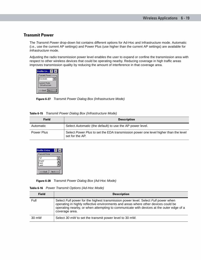
Wireless Applications 6 - 19
Transmit Power
The Transmit Power drop-down list contains different options for Ad-Hoc and Infrastructure mode. Automatic (i.e., use the current AP settings) and Power Plus (use higher than the current AP settings) are available for Infrastructure mode.
Adjusting the radio transmission power level enables the user to expand or confine the transmission area with respect to other wireless devices that could be operating nearby. Reducing coverage in high traffic areas improves transmission quality by reducing the amount of interference in that coverage area.
Figure 6-27 Transmit Power Dialog Box (Infrastructure Mode)
Figure 6-28 Transmit Power Dialog Box (Ad-Hoc Mode)
Table 6-15 Transmit Power Dialog Box (Infrastructure Mode)
Field Description
Automatic Select Automatic (the default) to use the AP power level.
Power Plus Select Power Plus to set the EDA transmission power one level higher than the level set for the AP.
Table 6-16 Power Transmit Options (Ad-Hoc Mode)
Field Description
Full Select Full power for the highest transmission power level. Select Full power when operating in highly reflective environments and areas where other devices could be operating nearby, or when attempting to communicate with devices at the outer edge of a coverage area.
30 mW Select 30 mW to set the transmit power level to 30 mW.
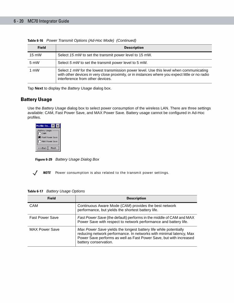
6 - 20 MC70 Integrator Guide
Tap Next to display the Battery Usage dialog box.
Battery Usage
Use the Battery Usage dialog box to select power consumption of the wireless LAN. There are three settings available: CAM, Fast Power Save, and MAX Power Save. Battery usage cannot be configured in Ad-Hoc profiles.
Figure 6-29 Battery Usage Dialog Box
15 mW Select 15 mW to set the transmit power level to 15 mW.
5 mW Select 5 mW to set the transmit power level to 5 mW.
1 mW Select 1 mW for the lowest transmission power level. Use this level when communicating with other devices in very close proximity, or in instances where you expect little or no radio interference from other devices.
Table 6-16 Power Transmit Options (Ad-Hoc Mode) (Continued)
Field Description
NOTE Power consumption is also related to the transmit power settings.
Table 6-17 Battery Usage Options
Field Description
CAM Continuous Aware Mode (CAM) provides the best network performance, but yields the shortest battery life.
Fast Power Save Fast Power Save (the default) performs in the middle of CAM and MAX Power Save with respect to network performance and battery life.
MAX Power Save Max Power Save yields the longest battery life while potentially reducing network performance. In networks with minimal latency, Max Power Save performs as well as Fast Power Save, but with increased battery conservation.
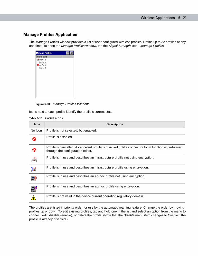
Wireless Applications 6 - 21
Manage Profiles Application
The Manage Profiles window provides a list of user-configured wireless profiles. Define up to 32 profiles at any one time. To open the Manage Profiles window, tap the Signal Strength icon - Manage Profiles.
Figure 6-30 Manage Profiles Window
Icons next to each profile identify the profile’s current state.
The profiles are listed in priority order for use by the automatic roaming feature. Change the order by moving profiles up or down. To edit existing profiles, tap and hold one in the list and select an option from the menu to connect, edit, disable (enable), or delete the profile. (Note that the Disable menu item changes to Enable if the profile is already disabled.)
Table 6-18 Profile Icons
Icon Description
No Icon Profile is not selected, but enabled.
Profile is disabled.
Profile is cancelled. A cancelled profile is disabled until a connect or login function is performed through the configuration editor.
Profile is in use and describes an infrastructure profile not using encryption.
Profile is in use and describes an infrastructure profile using encryption.
Profile is in use and describes an ad-hoc profile not using encryption.
Profile is in use and describes an ad-hoc profile using encryption.
Profile is not valid in the device current operating regulatory domain.
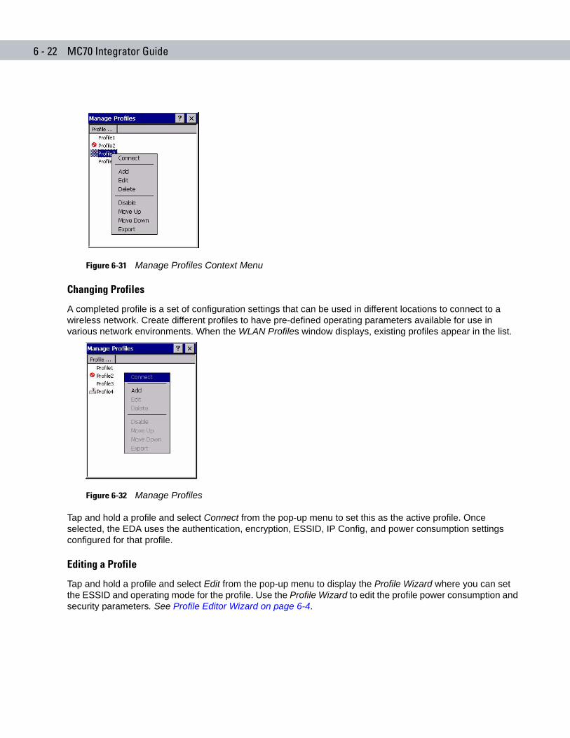
6 - 22 MC70 Integrator Guide
Figure 6-31 Manage Profiles Context Menu
Changing Profiles
A completed profile is a set of configuration settings that can be used in different locations to connect to a wireless network. Create different profiles to have pre-defined operating parameters available for use in various network environments. When the WLAN Profiles window displays, existing profiles appear in the list.
Figure 6-32 Manage Profiles
Tap and hold a profile and select Connect from the pop-up menu to set this as the active profile. Once selected, the EDA uses the authentication, encryption, ESSID, IP Config, and power consumption settings configured for that profile.
Editing a Profile
Tap and hold a profile and select Edit from the pop-up menu to display the Profile Wizard where you can set the ESSID and operating mode for the profile. Use the Profile Wizard to edit the profile power consumption and security parameters. See Profile Editor Wizard on page 6-4.
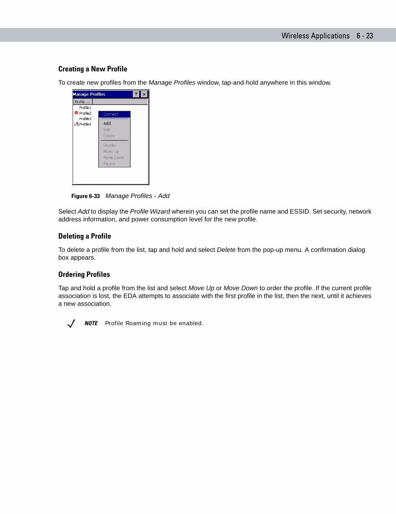
Wireless Applications 6 - 23
Creating a New Profile
To create new profiles from the Manage Profiles window, tap-and-hold anywhere in this window.
Figure 6-33 Manage Profiles - Add
Select Add to display the Profile Wizard wherein you can set the profile name and ESSID. Set security, network address information, and power consumption level for the new profile.
Deleting a Profile
To delete a profile from the list, tap and hold and select Delete from the pop-up menu. A confirmation dialog box appears.
Ordering Profiles
Tap and hold a profile from the list and select Move Up or Move Down to order the profile. If the current profile association is lost, the EDA attempts to associate with the first profile in the list, then the next, until it achieves a new association.
NOTE Profile Roaming must be enabled.
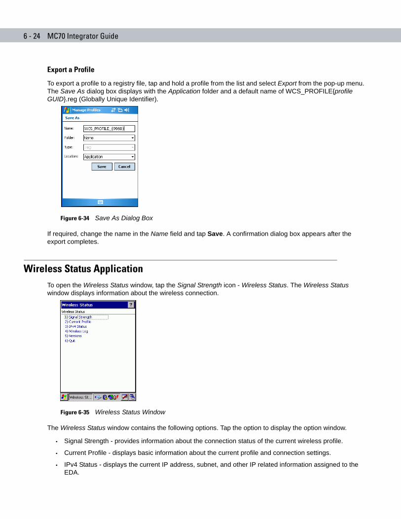
6 - 24 MC70 Integrator Guide
Export a Profile
To export a profile to a registry file, tap and hold a profile from the list and select Export from the pop-up menu. The Save As dialog box displays with the Application folder and a default name of WCS_PROFILE{profile GUID}.reg (Globally Unique Identifier).
Figure 6-34 Save As Dialog Box
If required, change the name in the Name field and tap Save. A confirmation dialog box appears after the export completes.
Wireless Status ApplicationTo open the Wireless Status window, tap the Signal Strength icon - Wireless Status. The Wireless Status window displays information about the wireless connection.
Figure 6-35 Wireless Status Window
The Wireless Status window contains the following options. Tap the option to display the option window.
• Signal Strength - provides information about the connection status of the current wireless profile.
• Current Profile - displays basic information about the current profile and connection settings.
• IPv4 Status - displays the current IP address, subnet, and other IP related information assigned to the EDA.
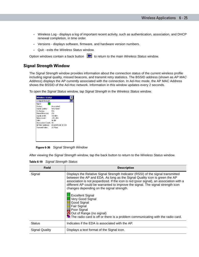
Wireless Applications 6 - 25
• Wireless Log - displays a log of important recent activity, such as authentication, association, and DHCP renewal completion, in time order.
• Versions - displays software, firmware, and hardware version numbers.
• Quit - exits the Wireless Status window.
Option windows contain a back button to return to the main Wireless Status window.
Signal Strength Window
The Signal Strength window provides information about the connection status of the current wireless profile including signal quality, missed beacons, and transmit retry statistics. The BSSID address (shown as AP MAC Address) displays the AP currently associated with the connection. In Ad-Hoc mode, the AP MAC Address shows the BSSID of the Ad-Hoc network. Information in this window updates every 2 seconds.
To open the Signal Status window, tap Signal Strength in the Wireless Status window.
Figure 6-36 Signal Strength Window
After viewing the Signal Strength window, tap the back button to return to the Wireless Status window.
Table 6-19 Signal Strength Status
Field Description
Signal Displays the Relative Signal Strength Indicator (RSSI) of the signal transmitted between the AP and EDA. As long as the Signal Quality icon is green the AP association is not jeopardized. If the icon is red (poor signal), an association with a different AP could be warranted to improve the signal. The signal strength icon changes depending on the signal strength.
Excellent Signal Very Good Signal Good Signal Fair Signal Poor Signal Out of Range (no signal) The radio card is off or there is a problem communicating with the radio card.
Status Indicates if the EDA is associated with the AP.
Signal Quality Displays a text format of the Signal icon.
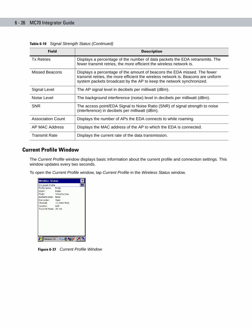
6 - 26 MC70 Integrator Guide
Current Profile Window
The Current Profile window displays basic information about the current profile and connection settings. This window updates every two seconds.
To open the Current Profile window, tap Current Profile in the Wireless Status window.
Figure 6-37 Current Profile Window
Tx Retries Displays a percentage of the number of data packets the EDA retransmits. The fewer transmit retries, the more efficient the wireless network is.
Missed Beacons Displays a percentage of the amount of beacons the EDA missed. The fewer transmit retries, the more efficient the wireless network is. Beacons are uniform system packets broadcast by the AP to keep the network synchronized.
Signal Level The AP signal level in decibels per milliwatt (dBm).
Noise Level The background interference (noise) level in decibels per milliwatt (dBm).
SNR The access point/EDA Signal to Noise Ratio (SNR) of signal strength to noise (interference) in decibels per milliwatt (dBm).
Association Count Displays the number of APs the EDA connects to while roaming.
AP MAC Address Displays the MAC address of the AP to which the EDA is connected.
Transmit Rate Displays the current rate of the data transmission.
Table 6-19 Signal Strength Status (Continued)
Field Description
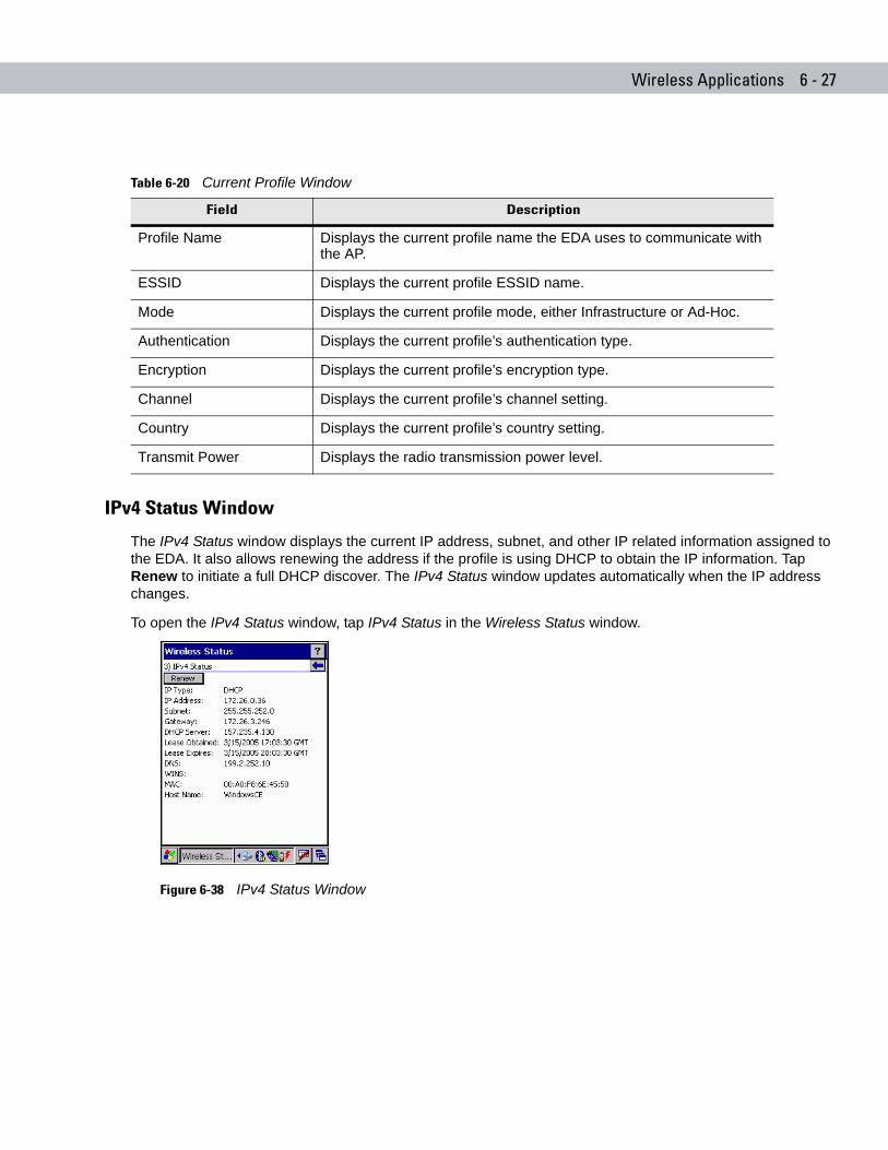
Wireless Applications 6 - 27
IPv4 Status Window
The IPv4 Status window displays the current IP address, subnet, and other IP related information assigned to the EDA. It also allows renewing the address if the profile is using DHCP to obtain the IP information. Tap Renew to initiate a full DHCP discover. The IPv4 Status window updates automatically when the IP address changes.
To open the IPv4 Status window, tap IPv4 Status in the Wireless Status window.
Figure 6-38 IPv4 Status Window
Table 6-20 Current Profile Window
Field Description
Profile Name Displays the current profile name the EDA uses to communicate with the AP.
ESSID Displays the current profile ESSID name.
Mode Displays the current profile mode, either Infrastructure or Ad-Hoc.
Authentication Displays the current profile’s authentication type.
Encryption Displays the current profile’s encryption type.
Channel Displays the current profile’s channel setting.
Country Displays the current profile’s country setting.
Transmit Power Displays the radio transmission power level.
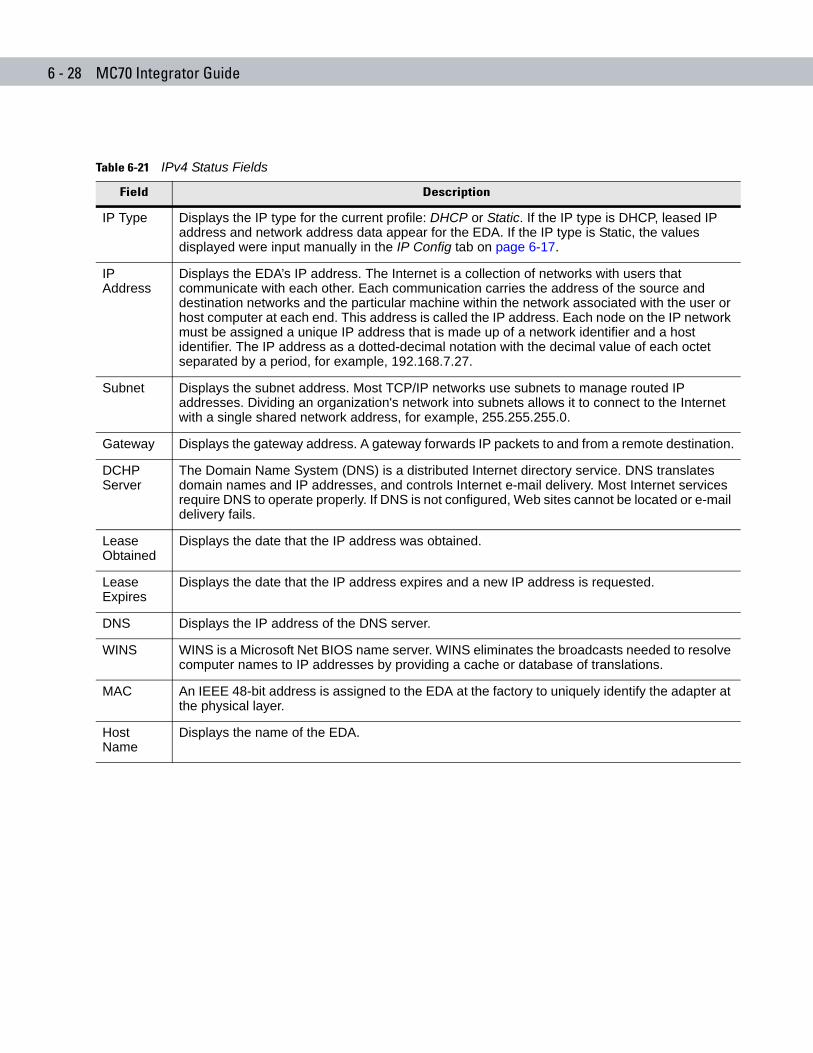
6 - 28 MC70 Integrator Guide
Table 6-21 IPv4 Status Fields
Field Description
IP Type Displays the IP type for the current profile: DHCP or Static. If the IP type is DHCP, leased IP address and network address data appear for the EDA. If the IP type is Static, the values displayed were input manually in the IP Config tab on page 6-17.
IP Address
Displays the EDA’s IP address. The Internet is a collection of networks with users that communicate with each other. Each communication carries the address of the source and destination networks and the particular machine within the network associated with the user or host computer at each end. This address is called the IP address. Each node on the IP network must be assigned a unique IP address that is made up of a network identifier and a host identifier. The IP address as a dotted-decimal notation with the decimal value of each octet separated by a period, for example, 192.168.7.27.
Subnet Displays the subnet address. Most TCP/IP networks use subnets to manage routed IP addresses. Dividing an organization's network into subnets allows it to connect to the Internet with a single shared network address, for example, 255.255.255.0.
Gateway Displays the gateway address. A gateway forwards IP packets to and from a remote destination.
DCHP Server
The Domain Name System (DNS) is a distributed Internet directory service. DNS translates domain names and IP addresses, and controls Internet e-mail delivery. Most Internet services require DNS to operate properly. If DNS is not configured, Web sites cannot be located or e-mail delivery fails.
Lease Obtained
Displays the date that the IP address was obtained.
Lease Expires
Displays the date that the IP address expires and a new IP address is requested.
DNS Displays the IP address of the DNS server.
WINS WINS is a Microsoft Net BIOS name server. WINS eliminates the broadcasts needed to resolve computer names to IP addresses by providing a cache or database of translations.
MAC An IEEE 48-bit address is assigned to the EDA at the factory to uniquely identify the adapter at the physical layer.
Host Name
Displays the name of the EDA.
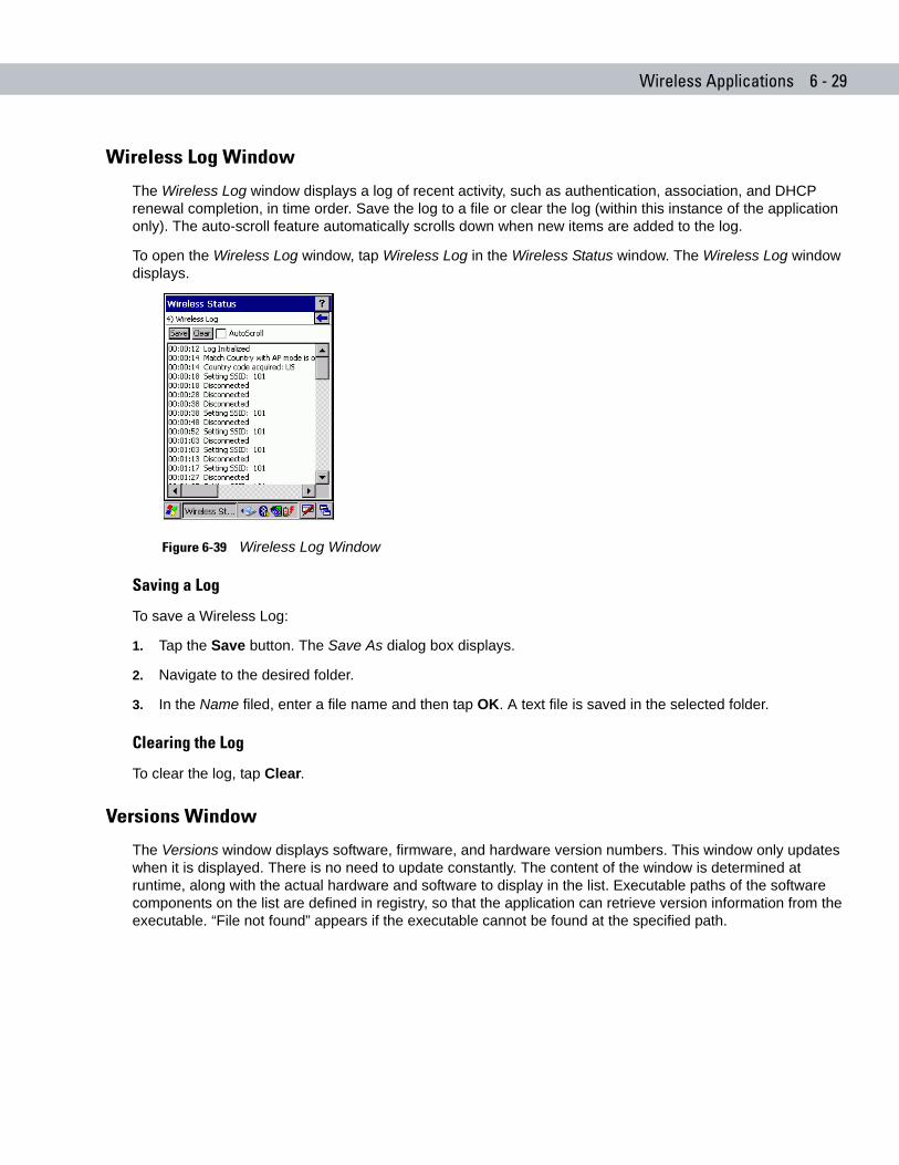
Wireless Applications 6 - 29
Wireless Log Window
The Wireless Log window displays a log of recent activity, such as authentication, association, and DHCP renewal completion, in time order. Save the log to a file or clear the log (within this instance of the application only). The auto-scroll feature automatically scrolls down when new items are added to the log.
To open the Wireless Log window, tap Wireless Log in the Wireless Status window. The Wireless Log window displays.
Figure 6-39 Wireless Log Window
Saving a Log
To save a Wireless Log:
1. Tap the Save button. The Save As dialog box displays.
2. Navigate to the desired folder.
3. In the Name filed, enter a file name and then tap OK. A text file is saved in the selected folder.
Clearing the Log
To clear the log, tap Clear.
Versions Window
The Versions window displays software, firmware, and hardware version numbers. This window only updates when it is displayed. There is no need to update constantly. The content of the window is determined at runtime, along with the actual hardware and software to display in the list. Executable paths of the software components on the list are defined in registry, so that the application can retrieve version information from the executable. “File not found” appears if the executable cannot be found at the specified path.
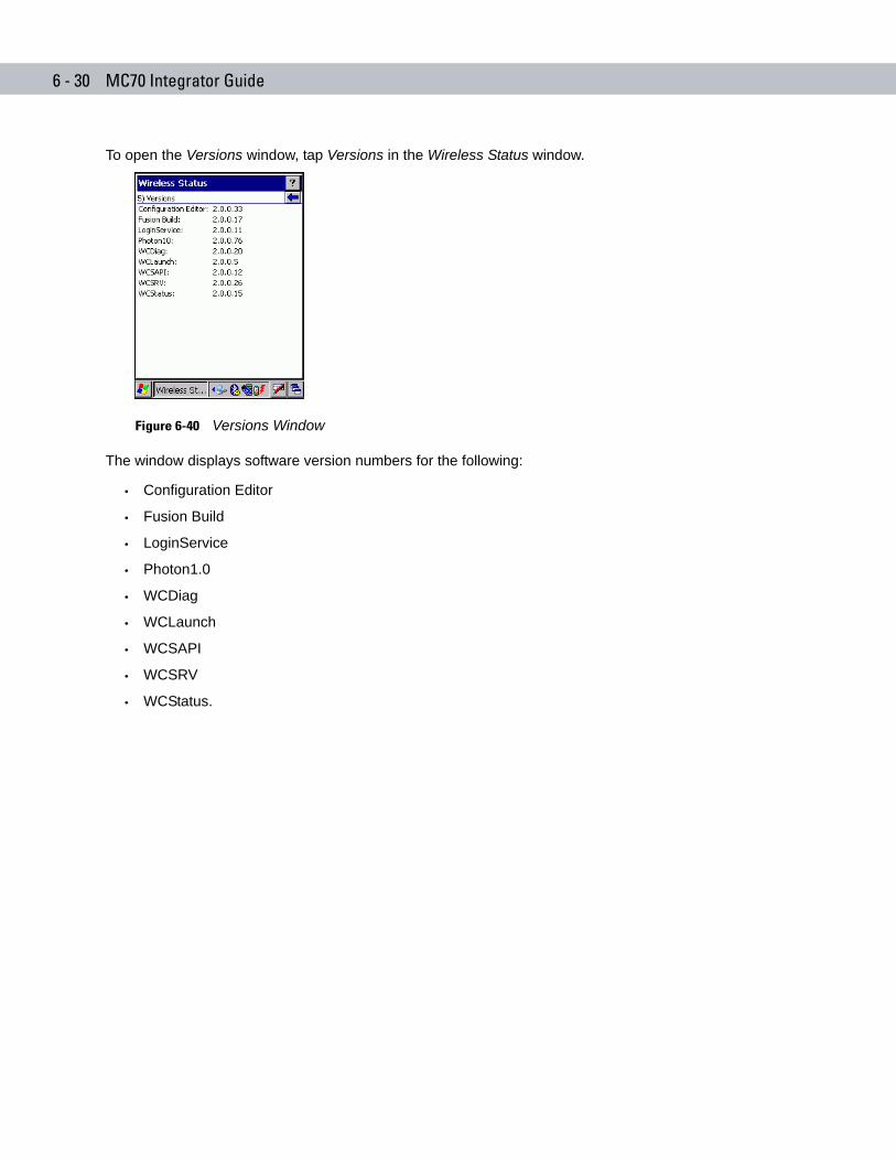
6 - 30 MC70 Integrator Guide
To open the Versions window, tap Versions in the Wireless Status window.
Figure 6-40 Versions Window
The window displays software version numbers for the following:
• Configuration Editor
• Fusion Build
• LoginService
• Photon1.0
• WCDiag
• WCLaunch
• WCSAPI
• WCSRV
• WCStatus.
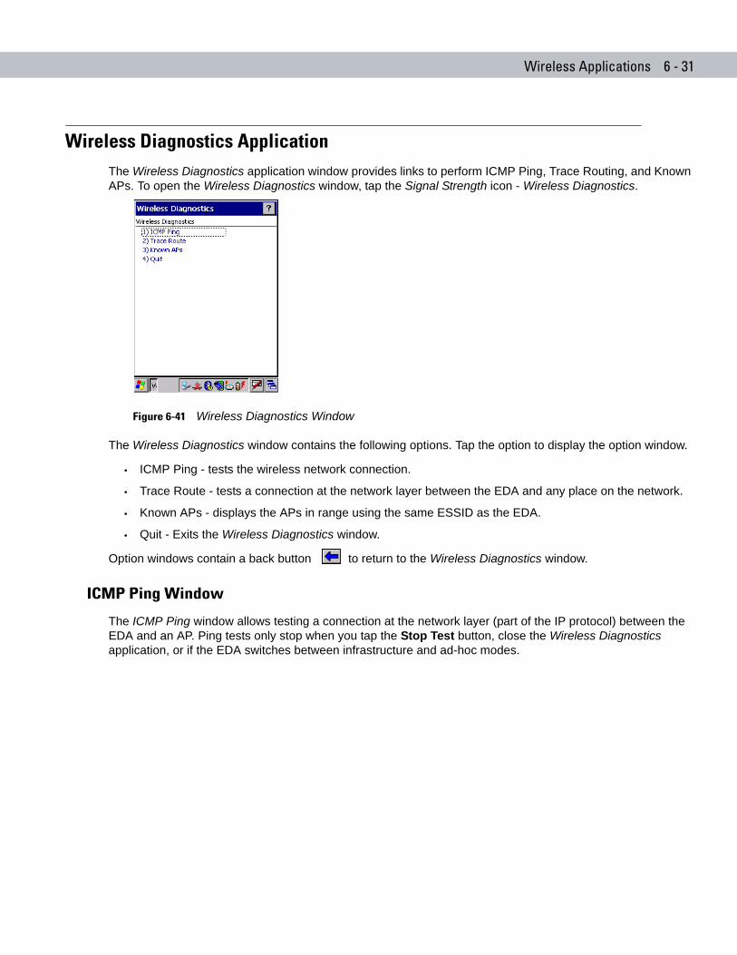
Wireless Applications 6 - 31
Wireless Diagnostics ApplicationThe Wireless Diagnostics application window provides links to perform ICMP Ping, Trace Routing, and Known APs. To open the Wireless Diagnostics window, tap the Signal Strength icon - Wireless Diagnostics.
Figure 6-41 Wireless Diagnostics Window
The Wireless Diagnostics window contains the following options. Tap the option to display the option window.
• ICMP Ping - tests the wireless network connection.
• Trace Route - tests a connection at the network layer between the EDA and any place on the network.
• Known APs - displays the APs in range using the same ESSID as the EDA.
• Quit - Exits the Wireless Diagnostics window.
Option windows contain a back button to return to the Wireless Diagnostics window.
ICMP Ping Window
The ICMP Ping window allows testing a connection at the network layer (part of the IP protocol) between the EDA and an AP. Ping tests only stop when you tap the Stop Test button, close the Wireless Diagnostics application, or if the EDA switches between infrastructure and ad-hoc modes.
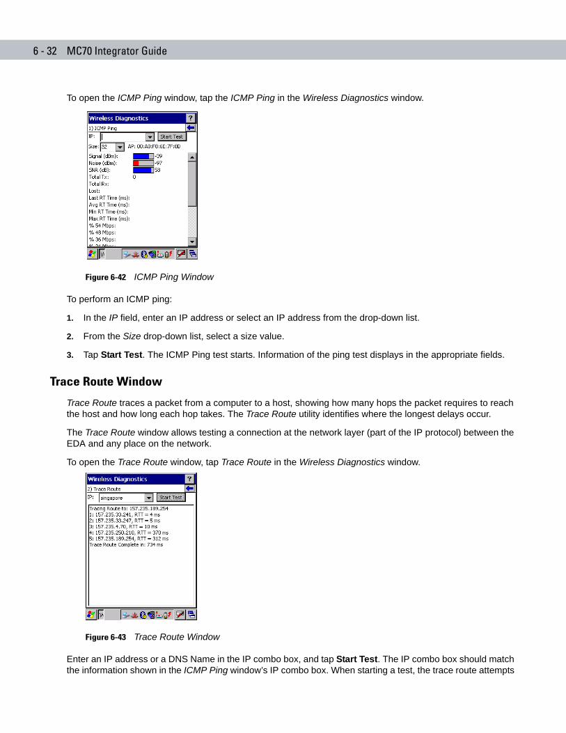
6 - 32 MC70 Integrator Guide
To open the ICMP Ping window, tap the ICMP Ping in the Wireless Diagnostics window.
Figure 6-42 ICMP Ping Window
To perform an ICMP ping:
1. In the IP field, enter an IP address or select an IP address from the drop-down list.
2. From the Size drop-down list, select a size value.
3. Tap Start Test. The ICMP Ping test starts. Information of the ping test displays in the appropriate fields.
Trace Route Window
Trace Route traces a packet from a computer to a host, showing how many hops the packet requires to reach the host and how long each hop takes. The Trace Route utility identifies where the longest delays occur.
The Trace Route window allows testing a connection at the network layer (part of the IP protocol) between the EDA and any place on the network.
To open the Trace Route window, tap Trace Route in the Wireless Diagnostics window.
Figure 6-43 Trace Route Window
Enter an IP address or a DNS Name in the IP combo box, and tap Start Test. The IP combo box should match the information shown in the ICMP Ping window’s IP combo box. When starting a test, the trace route attempts
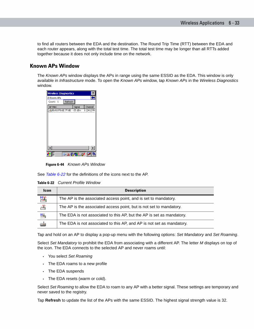
Wireless Applications 6 - 33
to find all routers between the EDA and the destination. The Round Trip Time (RTT) between the EDA and each router appears, along with the total test time. The total test time may be longer than all RTTs added together because it does not only include time on the network.
Known APs Window
The Known APs window displays the APs in range using the same ESSID as the EDA. This window is only available in Infrastructure mode. To open the Known APs window, tap Known APs in the Wireless Diagnostics window.
Figure 6-44 Known APs Window
See Table 6-22 for the definitions of the icons next to the AP.
Tap and hold on an AP to display a pop-up menu with the following options: Set Mandatory and Set Roaming.
Select Set Mandatory to prohibit the EDA from associating with a different AP. The letter M displays on top of the icon. The EDA connects to the selected AP and never roams until:
• You select Set Roaming
• The EDA roams to a new profile
• The EDA suspends
• The EDA resets (warm or cold).
Select Set Roaming to allow the EDA to roam to any AP with a better signal. These settings are temporary and never saved to the registry.
Tap Refresh to update the list of the APs with the same ESSID. The highest signal strength value is 32.
Table 6-22 Current Profile Window
Icon Description
The AP is the associated access point, and is set to mandatory.
The AP is the associated access point, but is not set to mandatory.
The EDA is not associated to this AP, but the AP is set as mandatory.
The EDA is not associated to this AP, and AP is not set as mandatory.
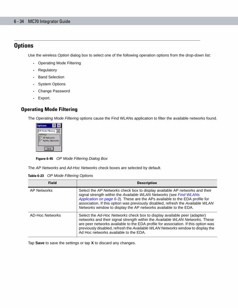
6 - 34 MC70 Integrator Guide
OptionsUse the wireless Option dialog box to select one of the following operation options from the drop-down list:
• Operating Mode Filtering
• Regulatory
• Band Selection
• System Options
• Change Password
• Export.
Operating Mode Filtering
The Operating Mode Filtering options cause the Find WLANs application to filter the available networks found.
Figure 6-45 OP Mode Filtering Dialog Box
The AP Networks and Ad-Hoc Networks check boxes are selected by default.
Tap Save to save the settings or tap X to discard any changes.
Table 6-23 OP Mode Filtering Options
Field Description
AP Networks Select the AP Networks check box to display available AP networks and their signal strength within the Available WLAN Networks (see Find WLANs Application on page 6-3). These are the APs available to the EDA profile for association. If this option was previously disabled, refresh the Available WLAN Networks window to display the AP networks available to the EDA.
AD-Hoc Networks Select the Ad-Hoc Networks check box to display available peer (adapter) networks and their signal strength within the Available WLAN Networks. These are peer networks available to the EDA profile for association. If this option was previously disabled, refresh the Available WLAN Networks window to display the Ad Hoc networks available to the EDA.
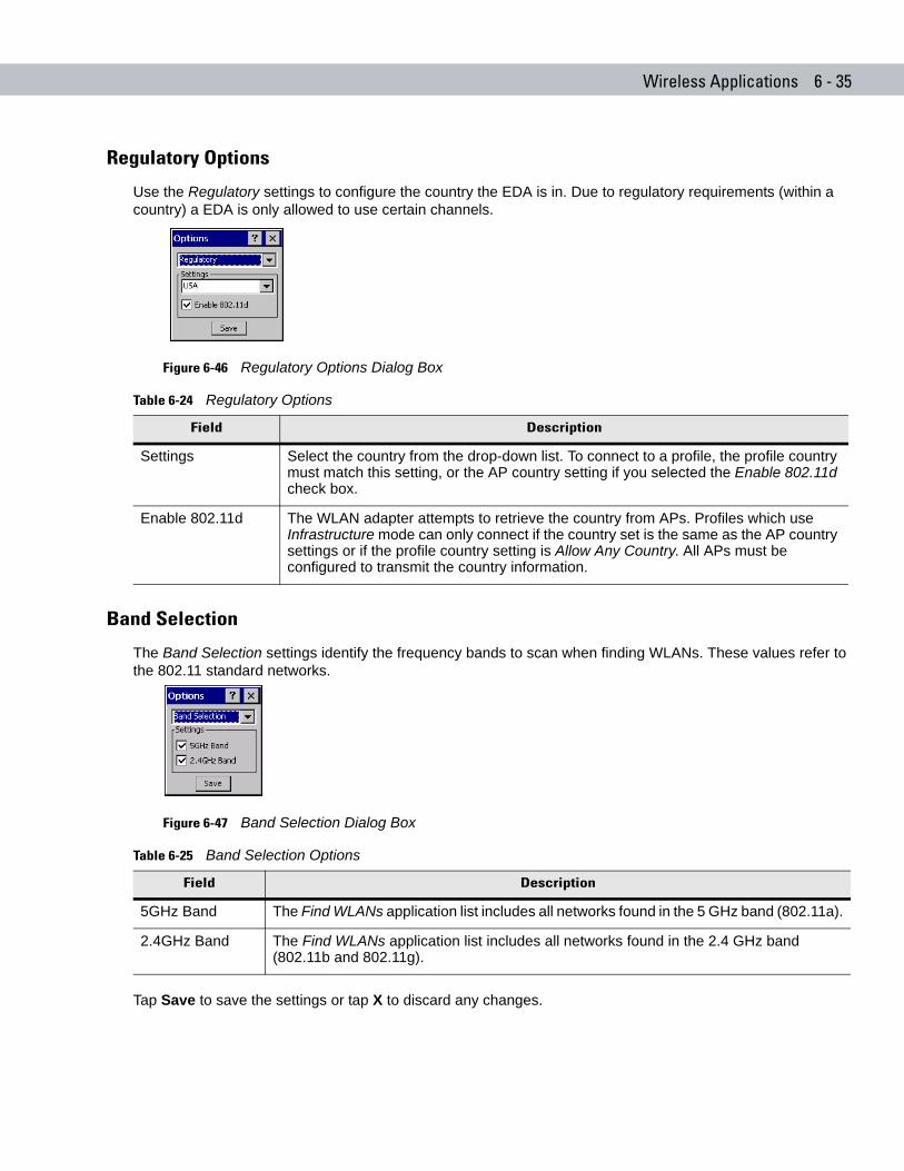
Wireless Applications 6 - 35
Regulatory Options
Use the Regulatory settings to configure the country the EDA is in. Due to regulatory requirements (within a country) a EDA is only allowed to use certain channels.
Figure 6-46 Regulatory Options Dialog Box
Band Selection
The Band Selection settings identify the frequency bands to scan when finding WLANs. These values refer to the 802.11 standard networks.
Figure 6-47 Band Selection Dialog Box
Tap Save to save the settings or tap X to discard any changes.
Table 6-24 Regulatory Options
Field Description
Settings Select the country from the drop-down list. To connect to a profile, the profile country must match this setting, or the AP country setting if you selected the Enable 802.11d check box.
Enable 802.11d The WLAN adapter attempts to retrieve the country from APs. Profiles which use Infrastructure mode can only connect if the country set is the same as the AP country settings or if the profile country setting is Allow Any Country. All APs must be configured to transmit the country information.
Table 6-25 Band Selection Options
Field Description
5GHz Band The Find WLANs application list includes all networks found in the 5 GHz band (802.11a).
2.4GHz Band The Find WLANs application list includes all networks found in the 2.4 GHz band (802.11b and 802.11g).
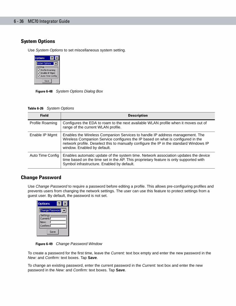
6 - 36 MC70 Integrator Guide
System Options
Use System Options to set miscellaneous system setting.
Figure 6-48 System Options Dialog Box
Change Password
Use Change Password to require a password before editing a profile. This allows pre-configuring profiles and prevents users from changing the network settings. The user can use this feature to protect settings from a guest user. By default, the password is not set.
Figure 6-49 Change Password Window
To create a password for the first time, leave the Current: text box empty and enter the new password in the New: and Confirm: text boxes. Tap Save.
To change an existing password, enter the current password in the Current: text box and enter the new password in the New: and Confirm: text boxes. Tap Save.
Table 6-26 System Options
Field Description
Profile Roaming Configures the EDA to roam to the next available WLAN profile when it moves out of range of the current WLAN profile.
Enable IP Mgmt Enables the Wireless Companion Services to handle IP address management. The Wireless Companion Service configures the IP based on what is configured in the network profile. Deselect this to manually configure the IP in the standard Windows IP window. Enabled by default.
Auto Time Config Enables automatic update of the system time. Network association updates the device time based on the time set in the AP. This proprietary feature is only supported with Symbol infrastructure. Enabled by default.
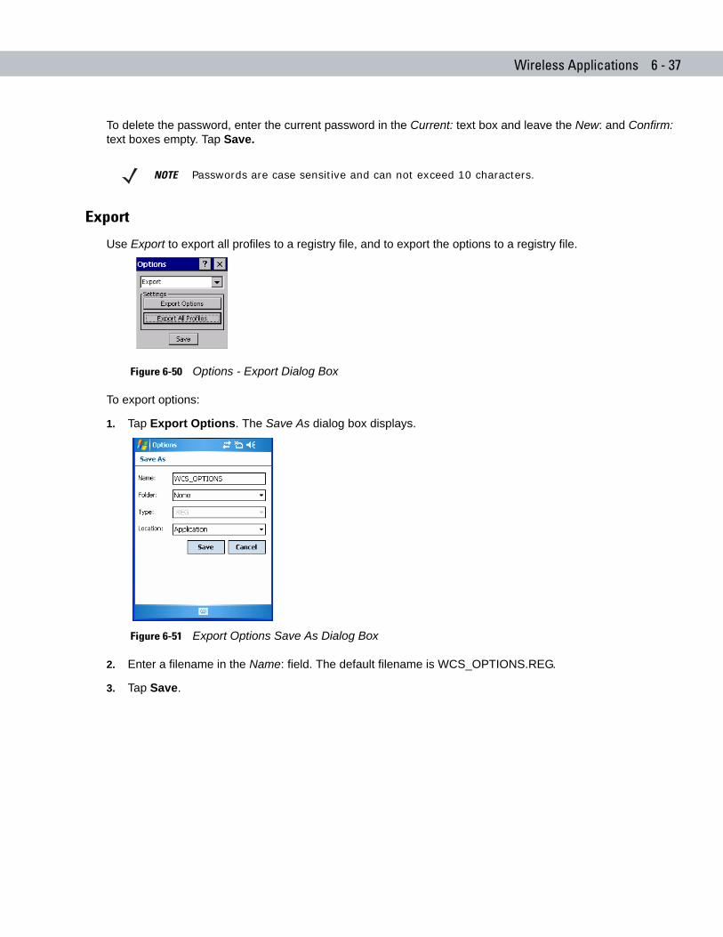
Wireless Applications 6 - 37
To delete the password, enter the current password in the Current: text box and leave the New: and Confirm: text boxes empty. Tap Save.
Export
Use Export to export all profiles to a registry file, and to export the options to a registry file.
Figure 6-50 Options - Export Dialog Box
To export options:
1. Tap Export Options. The Save As dialog box displays.
Figure 6-51 Export Options Save As Dialog Box
2. Enter a filename in the Name: field. The default filename is WCS_OPTIONS.REG.
3. Tap Save.
NOTE Passwords are case sensitive and can not exceed 10 characters.
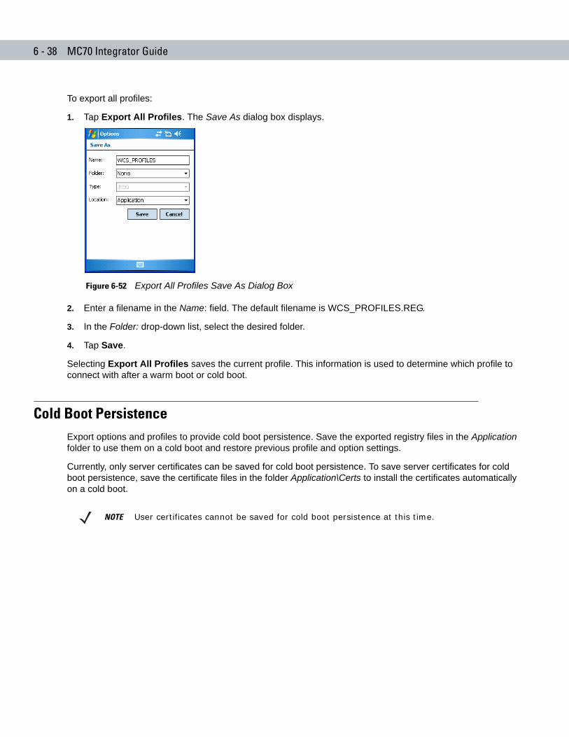
6 - 38 MC70 Integrator Guide
To export all profiles:
1. Tap Export All Profiles. The Save As dialog box displays.
Figure 6-52 Export All Profiles Save As Dialog Box
2. Enter a filename in the Name: field. The default filename is WCS_PROFILES.REG.
3. In the Folder: drop-down list, select the desired folder.
4. Tap Save.
Selecting Export All Profiles saves the current profile. This information is used to determine which profile to connect with after a warm boot or cold boot.
Cold Boot PersistenceExport options and profiles to provide cold boot persistence. Save the exported registry files in the Application folder to use them on a cold boot and restore previous profile and option settings.
Currently, only server certificates can be saved for cold boot persistence. To save server certificates for cold boot persistence, save the certificate files in the folder Application\Certs to install the certificates automatically on a cold boot.
NOTE User certificates cannot be saved for cold boot persistence at this time.
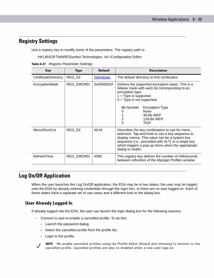
Wireless Applications 6 - 39
Registry SettingsUse a registry key to modify some of the parameters. The registry path is:
HKLM\SOFTWARE\Symbol Technologies, Inc.\Configuration Editor
Log On/Off ApplicationWhen the user launches the Log On/Off application, the EDA may be in two states; the user may be logged onto the EDA by already entering credentials through the login box, or there are no user logged on. Each of these states have a separate set of use cases and a different look to the dialog box.
User Already Logged In
If already logged into the EDA, the user can launch the login dialog box for the following reasons:
• Connect to and re-enable a cancelled profile. To do this:
- Launch the password dialog.
- Select the cancelled profile from the profile list.
- Login to the profile.
Table 6-27 Registry Parameter Settings
Key Type Default Description
CertificateDirectory REG_SZ \\Windows The default directory to find certificates.
EncryptionMask REG_DWORD 0x0000001F Defines the supported encryption types. This is a bitwise mask with each bit corresponding to an encryption type. 1 = Type is supported0 = Type is not supported
Bit Number Encryption Type0 None1 40-Bit WEP2 128-Bit WEP3 TKIP
MenuShortCut REG_SZ Alt-M Describes the key combination to use for menu selection. Tap-and-hold or use a key sequence to display menus. This value can be a system key sequence (i.e., preceded with ALT) or a single key which triggers a pop-up menu when the appropriate dialog is visible.
RefreshTime REG_DWORD 4000 This registry key defines the number of milliseconds between refreshes of the Manage Profiles window.
NOTE Re-enable cancelled profiles using the Profile Editor Wizard and choosing to connect to the cancelled profile. Cancelled profiles are also re-enabled when a new user logs on.
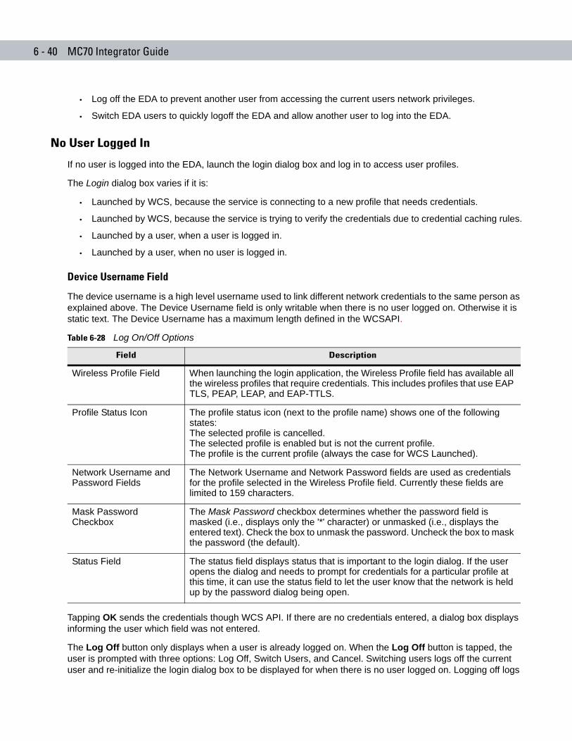
6 - 40 MC70 Integrator Guide
• Log off the EDA to prevent another user from accessing the current users network privileges.
• Switch EDA users to quickly logoff the EDA and allow another user to log into the EDA.
No User Logged In
If no user is logged into the EDA, launch the login dialog box and log in to access user profiles.
The Login dialog box varies if it is:
• Launched by WCS, because the service is connecting to a new profile that needs credentials.
• Launched by WCS, because the service is trying to verify the credentials due to credential caching rules.
• Launched by a user, when a user is logged in.
• Launched by a user, when no user is logged in.
Device Username Field
The device username is a high level username used to link different network credentials to the same person as explained above. The Device Username field is only writable when there is no user logged on. Otherwise it is static text. The Device Username has a maximum length defined in the WCSAPI.
Tapping OK sends the credentials though WCS API. If there are no credentials entered, a dialog box displays informing the user which field was not entered.
The Log Off button only displays when a user is already logged on. When the Log Off button is tapped, the user is prompted with three options: Log Off, Switch Users, and Cancel. Switching users logs off the current user and re-initialize the login dialog box to be displayed for when there is no user logged on. Logging off logs
Table 6-28 Log On/Off Options
Field Description
Wireless Profile Field When launching the login application, the Wireless Profile field has available all the wireless profiles that require credentials. This includes profiles that use EAP TLS, PEAP, LEAP, and EAP-TTLS.
Profile Status Icon The profile status icon (next to the profile name) shows one of the following states:The selected profile is cancelled.The selected profile is enabled but is not the current profile.The profile is the current profile (always the case for WCS Launched).
Network Username and Password Fields
The Network Username and Network Password fields are used as credentials for the profile selected in the Wireless Profile field. Currently these fields are limited to 159 characters.
Mask Password Checkbox
The Mask Password checkbox determines whether the password field is masked (i.e., displays only the '*' character) or unmasked (i.e., displays the entered text). Check the box to unmask the password. Uncheck the box to mask the password (the default).
Status Field The status field displays status that is important to the login dialog. If the user opens the dialog and needs to prompt for credentials for a particular profile at this time, it can use the status field to let the user know that the network is held up by the password dialog being open.

Wireless Applications 6 - 41
off the current user and close the login dialog box. Tapping Cancel closes the Log Off dialog box and the Login dialog box displays.
When the user is logged off, the EDA only roams to profiles that do not require credentials or to profiles that were created with the credentials entered into the profile
The Cancel button closes the dialog without logging into the network. If the login dialog was launched by the wCS and not by the user, tapping Cancel first causes a message box to display a warning that the cancel disables the current profile. If the user still chooses to cancel the login at this point, the profile is cancelled.
Once a profile is cancelled, the profile is suppressed until a user actively re-enables it or a new user logs onto the EDA.

6 - 42 MC70 Integrator Guide
Chapter 7 Maintenance and Troubleshooting
Chapter 7
Chapter 7 Maintenance and TroubleshootingIntroduction
This chapter includes instructions on cleaning and storing the EDA, and provides troubleshooting solutions for potential problems during EDA operation.
Maintaining the EDAFor trouble-free service, observe the following tips when using the EDA:
• Do not scratch the screen of the EDA. When working with the EDA, use the supplied stylus or plastic-tipped pens intended for use with a touch-sensitive screen. Never use an actual pen or pencil or other sharp object on the surface of the EDA screen.
Symbol recommends using a screen protector, p/n KT-67525-01.
• The touch-sensitive screen of the EDA is glass. Do not to drop the EDA or subject it to strong impact.
• Protect the EDA from temperature extremes. Do not leave it on the dashboard of a car on a hot day, and keep it away from heat sources.
• Do not store or use the EDA in any location that is dusty, damp, or wet.
• Use a soft lens cloth to clean the EDA. If the surface of the EDA screen becomes soiled, clean it with a soft cloth moistened with a diluted window-cleaning solution.
• Periodically replace the rechargeable battery to ensure maximum battery life and product performance. Battery life depends on individual usage patterns.
• A screen protector is applied to the EDA. Symbol recommends using this to minimize wear and tear. Screen protectors enhance the usability and durability of touch screen displays. Benefits include:
- Protection from scratches and gouges
- Durable writing and touch surface with tactile feel
- Abrasion and chemical resistance
- Glare reduction
- Keeping the device’s screen looking new
- Quick and easy installation.
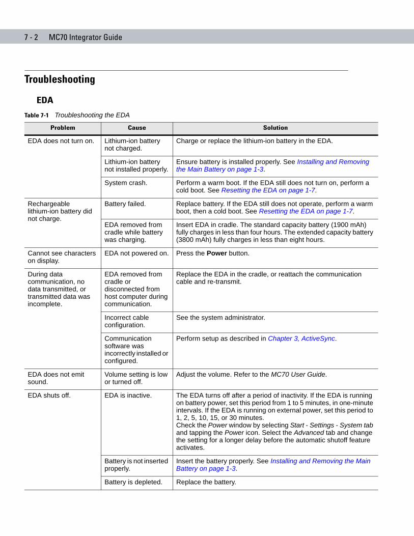
7 - 2 MC70 Integrator Guide
Troubleshooting
EDA
Table 7-1 Troubleshooting the EDA
Problem Cause Solution
EDA does not turn on. Lithium-ion battery not charged.
Charge or replace the lithium-ion battery in the EDA.
Lithium-ion battery not installed properly.
Ensure battery is installed properly. See Installing and Removing the Main Battery on page 1-3.
System crash. Perform a warm boot. If the EDA still does not turn on, perform a cold boot. See Resetting the EDA on page 1-7.
Rechargeable lithium-ion battery did not charge.
Battery failed. Replace battery. If the EDA still does not operate, perform a warm boot, then a cold boot. See Resetting the EDA on page 1-7.
EDA removed from cradle while battery was charging.
Insert EDA in cradle. The standard capacity battery (1900 mAh) fully charges in less than four hours. The extended capacity battery (3800 mAh) fully charges in less than eight hours.
Cannot see characters on display.
EDA not powered on. Press the Power button.
During data communication, no data transmitted, or transmitted data was incomplete.
EDA removed from cradle or disconnected from host computer during communication.
Replace the EDA in the cradle, or reattach the communication cable and re-transmit.
Incorrect cable configuration.
See the system administrator.
Communication software was incorrectly installed or configured.
Perform setup as described in Chapter 3, ActiveSync.
EDA does not emit sound.
Volume setting is low or turned off.
Adjust the volume. Refer to the MC70 User Guide.
EDA shuts off. EDA is inactive. The EDA turns off after a period of inactivity. If the EDA is running on battery power, set this period from 1 to 5 minutes, in one-minute intervals. If the EDA is running on external power, set this period to 1, 2, 5, 10, 15, or 30 minutes.Check the Power window by selecting Start - Settings - System tab and tapping the Power icon. Select the Advanced tab and change the setting for a longer delay before the automatic shutoff feature activates.
Battery is not inserted properly.
Insert the battery properly. See Installing and Removing the Main Battery on page 1-3.
Battery is depleted. Replace the battery.
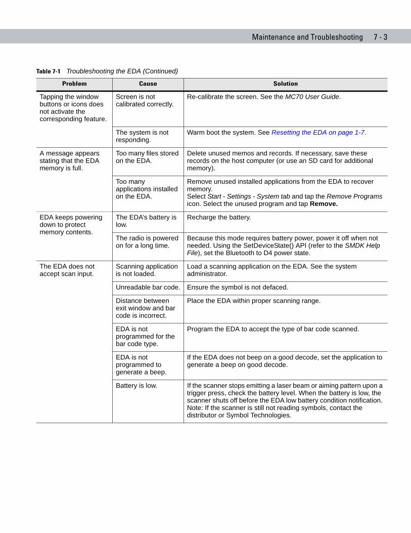
Maintenance and Troubleshooting 7 - 3
Tapping the window buttons or icons does not activate the corresponding feature.
Screen is not calibrated correctly.
Re-calibrate the screen. See the MC70 User Guide.
The system is not responding.
Warm boot the system. See Resetting the EDA on page 1-7.
A message appears stating that the EDA memory is full.
Too many files stored on the EDA.
Delete unused memos and records. If necessary, save these records on the host computer (or use an SD card for additional memory).
Too many applications installed on the EDA.
Remove unused installed applications from the EDA to recover memory. Select Start - Settings - System tab and tap the Remove Programs icon. Select the unused program and tap Remove.
EDA keeps powering down to protect memory contents.
The EDA’s battery is low.
Recharge the battery.
The radio is powered on for a long time.
Because this mode requires battery power, power it off when not needed. Using the SetDeviceState() API (refer to the SMDK Help File), set the Bluetooth to D4 power state.
The EDA does not accept scan input.
Scanning application is not loaded.
Load a scanning application on the EDA. See the system administrator.
Unreadable bar code. Ensure the symbol is not defaced.
Distance between exit window and bar code is incorrect.
Place the EDA within proper scanning range.
EDA is not programmed for the bar code type.
Program the EDA to accept the type of bar code scanned.
EDA is not programmed to generate a beep.
If the EDA does not beep on a good decode, set the application to generate a beep on good decode.
Battery is low. If the scanner stops emitting a laser beam or aiming pattern upon a trigger press, check the battery level. When the battery is low, the scanner shuts off before the EDA low battery condition notification. Note: If the scanner is still not reading symbols, contact the distributor or Symbol Technologies.
Table 7-1 Troubleshooting the EDA (Continued)
Problem Cause Solution
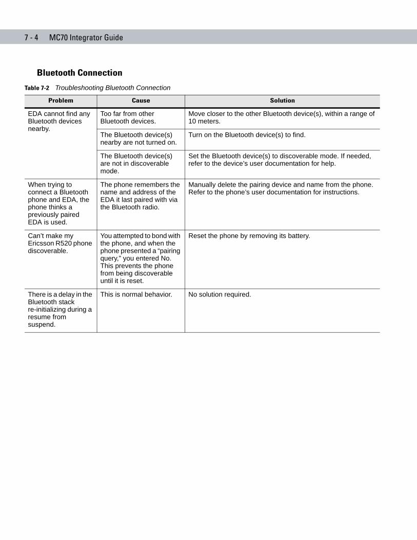
7 - 4 MC70 Integrator Guide
Bluetooth Connection
Table 7-2 Troubleshooting Bluetooth Connection
Problem Cause Solution
EDA cannot find any Bluetooth devices nearby.
Too far from other Bluetooth devices.
Move closer to the other Bluetooth device(s), within a range of 10 meters.
The Bluetooth device(s) nearby are not turned on.
Turn on the Bluetooth device(s) to find.
The Bluetooth device(s) are not in discoverable mode.
Set the Bluetooth device(s) to discoverable mode. If needed, refer to the device’s user documentation for help.
When trying to connect a Bluetooth phone and EDA, the phone thinks a previously paired EDA is used.
The phone remembers the name and address of the EDA it last paired with via the Bluetooth radio.
Manually delete the pairing device and name from the phone. Refer to the phone’s user documentation for instructions.
Can’t make my Ericsson R520 phone discoverable.
You attempted to bond with the phone, and when the phone presented a “pairing query,” you entered No. This prevents the phone from being discoverable until it is reset.
Reset the phone by removing its battery.
There is a delay in the Bluetooth stack re-initializing during a resume from suspend.
This is normal behavior. No solution required.
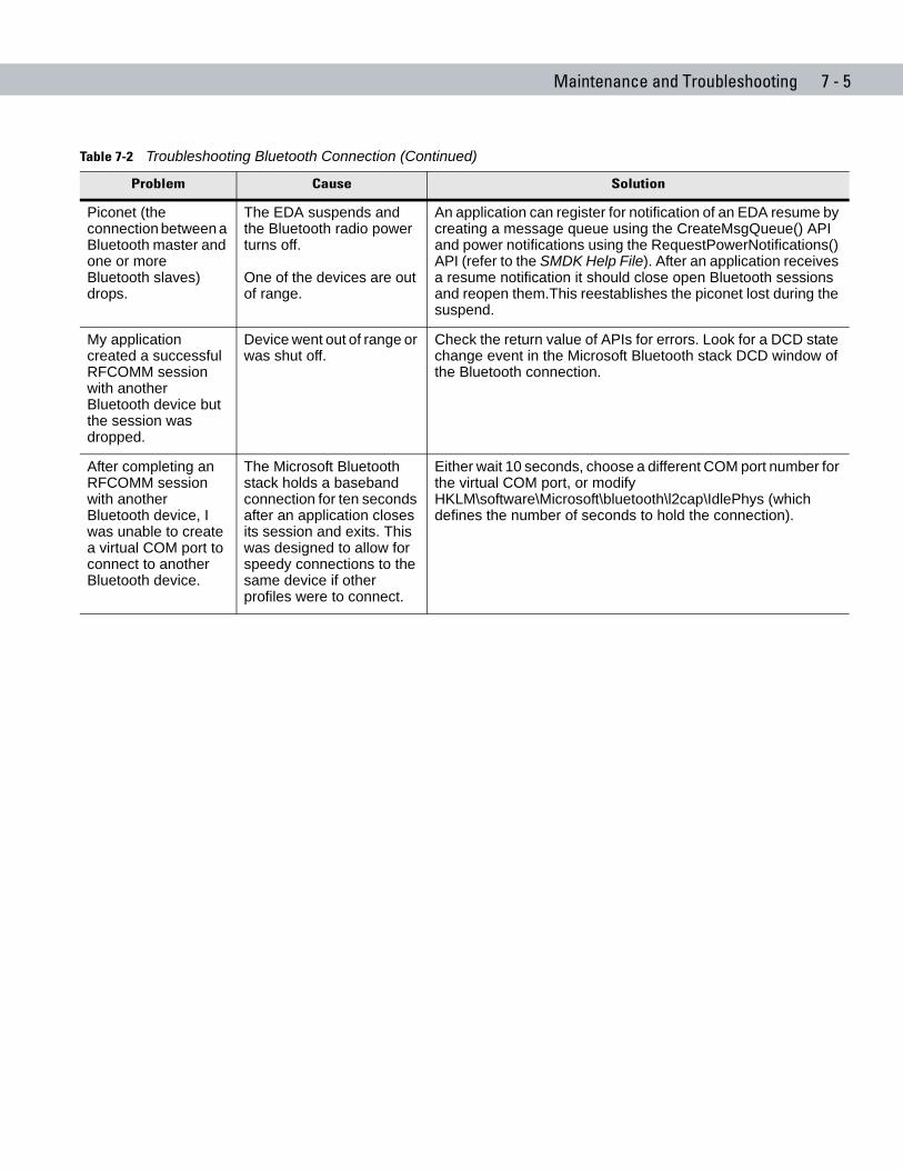
Maintenance and Troubleshooting 7 - 5
Piconet (the connection between a Bluetooth master and one or more Bluetooth slaves) drops.
The EDA suspends and the Bluetooth radio power turns off.
One of the devices are out of range.
An application can register for notification of an EDA resume by creating a message queue using the CreateMsgQueue() API and power notifications using the RequestPowerNotifications() API (refer to the SMDK Help File). After an application receives a resume notification it should close open Bluetooth sessions and reopen them.This reestablishes the piconet lost during the suspend.
My application created a successful RFCOMM session with another Bluetooth device but the session was dropped.
Device went out of range or was shut off.
Check the return value of APIs for errors. Look for a DCD state change event in the Microsoft Bluetooth stack DCD window of the Bluetooth connection.
After completing an RFCOMM session with another Bluetooth device, I was unable to create a virtual COM port to connect to another Bluetooth device.
The Microsoft Bluetooth stack holds a baseband connection for ten seconds after an application closes its session and exits. This was designed to allow for speedy connections to the same device if other profiles were to connect.
Either wait 10 seconds, choose a different COM port number for the virtual COM port, or modify HKLM\software\Microsoft\bluetooth\l2cap\IdlePhys (which defines the number of seconds to hold the connection).
Table 7-2 Troubleshooting Bluetooth Connection (Continued)
Problem Cause Solution
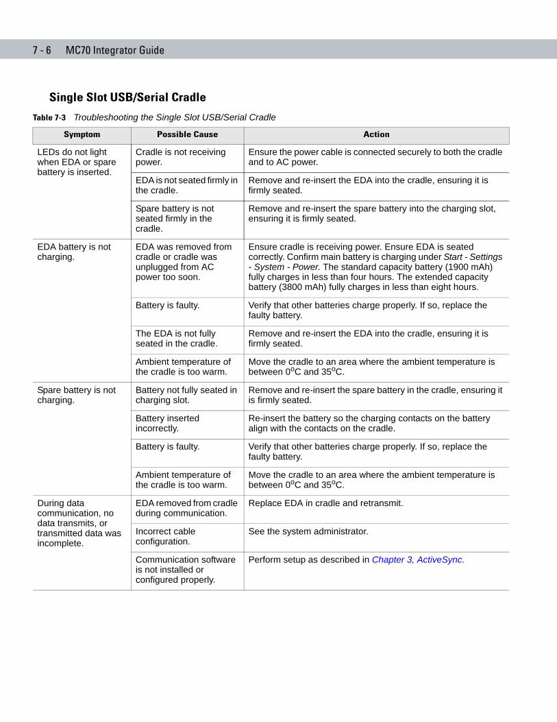
7 - 6 MC70 Integrator Guide
Single Slot USB/Serial Cradle
Table 7-3 Troubleshooting the Single Slot USB/Serial Cradle
Symptom Possible Cause Action
LEDs do not light when EDA or spare battery is inserted.
Cradle is not receiving power.
Ensure the power cable is connected securely to both the cradle and to AC power.
EDA is not seated firmly in the cradle.
Remove and re-insert the EDA into the cradle, ensuring it is firmly seated.
Spare battery is not seated firmly in the cradle.
Remove and re-insert the spare battery into the charging slot, ensuring it is firmly seated.
EDA battery is not charging.
EDA was removed from cradle or cradle was unplugged from AC power too soon.
Ensure cradle is receiving power. Ensure EDA is seated correctly. Confirm main battery is charging under Start - Settings - System - Power. The standard capacity battery (1900 mAh) fully charges in less than four hours. The extended capacity battery (3800 mAh) fully charges in less than eight hours.
Battery is faulty. Verify that other batteries charge properly. If so, replace the faulty battery.
The EDA is not fully seated in the cradle.
Remove and re-insert the EDA into the cradle, ensuring it is firmly seated.
Ambient temperature of the cradle is too warm.
Move the cradle to an area where the ambient temperature is between 0oC and 35oC.
Spare battery is not charging.
Battery not fully seated in charging slot.
Remove and re-insert the spare battery in the cradle, ensuring it is firmly seated.
Battery inserted incorrectly.
Re-insert the battery so the charging contacts on the battery align with the contacts on the cradle.
Battery is faulty. Verify that other batteries charge properly. If so, replace the faulty battery.
Ambient temperature of the cradle is too warm.
Move the cradle to an area where the ambient temperature is between 0oC and 35oC.
During data communication, no data transmits, or transmitted data was incomplete.
EDA removed from cradle during communication.
Replace EDA in cradle and retransmit.
Incorrect cable configuration.
See the system administrator.
Communication software is not installed or configured properly.
Perform setup as described in Chapter 3, ActiveSync.
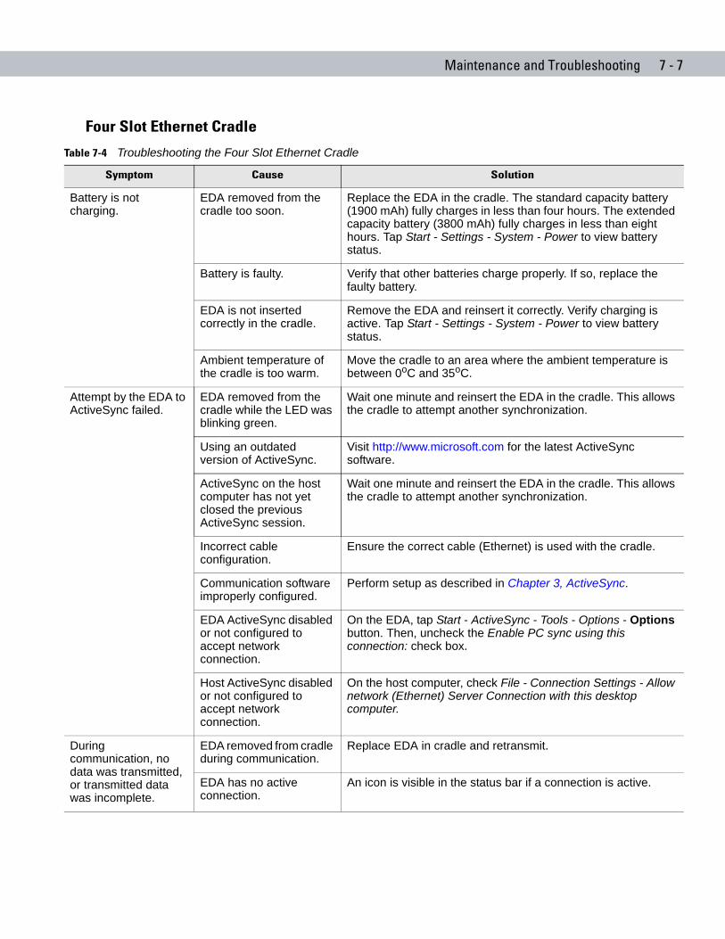
Maintenance and Troubleshooting 7 - 7
Four Slot Ethernet Cradle
Table 7-4 Troubleshooting the Four Slot Ethernet Cradle
Symptom Cause Solution
Battery is not charging.
EDA removed from the cradle too soon.
Replace the EDA in the cradle. The standard capacity battery (1900 mAh) fully charges in less than four hours. The extended capacity battery (3800 mAh) fully charges in less than eight hours. Tap Start - Settings - System - Power to view battery status.
Battery is faulty. Verify that other batteries charge properly. If so, replace the faulty battery.
EDA is not inserted correctly in the cradle.
Remove the EDA and reinsert it correctly. Verify charging is active. Tap Start - Settings - System - Power to view battery status.
Ambient temperature of the cradle is too warm.
Move the cradle to an area where the ambient temperature is between 0oC and 35oC.
Attempt by the EDA to ActiveSync failed.
EDA removed from the cradle while the LED was blinking green.
Wait one minute and reinsert the EDA in the cradle. This allows the cradle to attempt another synchronization.
Using an outdated version of ActiveSync.
Visit http://www.microsoft.com for the latest ActiveSync software.
ActiveSync on the host computer has not yet closed the previous ActiveSync session.
Wait one minute and reinsert the EDA in the cradle. This allows the cradle to attempt another synchronization.
Incorrect cable configuration.
Ensure the correct cable (Ethernet) is used with the cradle.
Communication software improperly configured.
Perform setup as described in Chapter 3, ActiveSync.
EDA ActiveSync disabled or not configured to accept network connection.
On the EDA, tap Start - ActiveSync - Tools - Options - Options button. Then, uncheck the Enable PC sync using this connection: check box.
Host ActiveSync disabled or not configured to accept network connection.
On the host computer, check File - Connection Settings - Allow network (Ethernet) Server Connection with this desktop computer.
During communication, no data was transmitted, or transmitted data was incomplete.
EDA removed from cradle during communication.
Replace EDA in cradle and retransmit.
EDA has no active connection.
An icon is visible in the status bar if a connection is active.
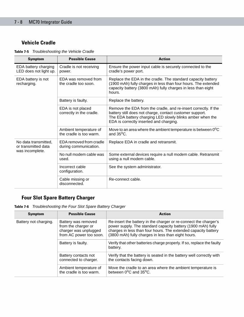
7 - 8 MC70 Integrator Guide
Vehicle Cradle
Four Slot Spare Battery Charger
Table 7-5 Troubleshooting the Vehicle Cradle
Symptom Possible Cause Action
EDA battery charging LED does not light up.
Cradle is not receiving power.
Ensure the power input cable is securely connected to the cradle’s power port.
EDA battery is not recharging.
EDA was removed from the cradle too soon.
Replace the EDA in the cradle. The standard capacity battery (1900 mAh) fully charges in less than four hours. The extended capacity battery (3800 mAh) fully charges in less than eight hours.
Battery is faulty. Replace the battery.
EDA is not placed correctly in the cradle.
Remove the EDA from the cradle, and re-insert correctly. If the battery still does not charge, contact customer support.The EDA battery charging LED slowly blinks amber when the EDA is correctly inserted and charging.
Ambient temperature of the cradle is too warm.
Move to an area where the ambient temperature is between 0oC and 35oC.
No data transmitted, or transmitted data was incomplete.
EDA removed from cradle during communication.
Replace EDA in cradle and retransmit.
No null modem cable was used.
Some external devices require a null modem cable. Retransmit using a null modem cable.
Incorrect cable configuration.
See the system administrator.
Cable missing or disconnected.
Re-connect cable.
Table 7-6 Troubleshooting the Four Slot Spare Battery Charger
Symptom Possible Cause Action
Battery not charging. Battery was removed from the charger or charger was unplugged from AC power too soon.
Re-insert the battery in the charger or re-connect the charger’s power supply. The standard capacity battery (1900 mAh) fully charges in less than four hours. The extended capacity battery (3800 mAh) fully charges in less than eight hours.
Battery is faulty. Verify that other batteries charge properly. If so, replace the faulty battery.
Battery contacts not connected to charger.
Verify that the battery is seated in the battery well correctly with the contacts facing down.
Ambient temperature of the cradle is too warm.
Move the cradle to an area where the ambient temperature is between 0oC and 35oC.
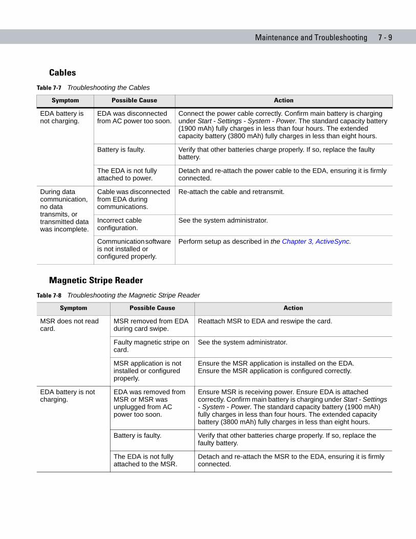
Maintenance and Troubleshooting 7 - 9
Cables
Magnetic Stripe Reader
Table 7-7 Troubleshooting the Cables
Symptom Possible Cause Action
EDA battery is not charging.
EDA was disconnected from AC power too soon.
Connect the power cable correctly. Confirm main battery is charging under Start - Settings - System - Power. The standard capacity battery (1900 mAh) fully charges in less than four hours. The extended capacity battery (3800 mAh) fully charges in less than eight hours.
Battery is faulty. Verify that other batteries charge properly. If so, replace the faulty battery.
The EDA is not fully attached to power.
Detach and re-attach the power cable to the EDA, ensuring it is firmly connected.
During data communication, no data transmits, or transmitted data was incomplete.
Cable was disconnected from EDA during communications.
Re-attach the cable and retransmit.
Incorrect cable configuration.
See the system administrator.
Communication software is not installed or configured properly.
Perform setup as described in the Chapter 3, ActiveSync.
Table 7-8 Troubleshooting the Magnetic Stripe Reader
Symptom Possible Cause Action
MSR does not read card.
MSR removed from EDA during card swipe.
Reattach MSR to EDA and reswipe the card.
Faulty magnetic stripe on card.
See the system administrator.
MSR application is not installed or configured properly.
Ensure the MSR application is installed on the EDA. Ensure the MSR application is configured correctly.
EDA battery is not charging.
EDA was removed from MSR or MSR was unplugged from AC power too soon.
Ensure MSR is receiving power. Ensure EDA is attached correctly. Confirm main battery is charging under Start - Settings - System - Power. The standard capacity battery (1900 mAh) fully charges in less than four hours. The extended capacity battery (3800 mAh) fully charges in less than eight hours.
Battery is faulty. Verify that other batteries charge properly. If so, replace the faulty battery.
The EDA is not fully attached to the MSR.
Detach and re-attach the MSR to the EDA, ensuring it is firmly connected.
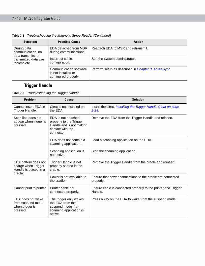
7 - 10 MC70 Integrator Guide
Trigger Handle
During data communication, no data transmits, or transmitted data was incomplete.
EDA detached from MSR during communications.
Reattach EDA to MSR and retransmit.
Incorrect cable configuration.
See the system administrator.
Communication software is not installed or configured properly.
Perform setup as described in Chapter 3, ActiveSync.
Table 7-8 Troubleshooting the Magnetic Stripe Reader (Continued)
Symptom Possible Cause Action
Table 7-9 Troubleshooting the Trigger Handle
Problem Cause Solution
Cannot insert EDA in Trigger Handle.
Cleat is not installed on the EDA.
Install the cleat. Installing the Trigger Handle Cleat on page 2-23.
Scan line does not appear when trigger is pressed.
EDA is not attached properly to the Trigger Handle and is not making contact with the connector.
Remove the EDA from the Trigger Handle and reinsert.
EDA does not contain a scanning application.
Load a scanning application on the EDA.
Scanning application is not active.
Start the scanning application.
EDA battery does not charge when Trigger Handle is placed in a cradle.
Trigger Handle is not properly seated in the cradle.
Remove the Trigger Handle from the cradle and reinsert.
Power is not available to the cradle.
Ensure that power connections to the cradle are connected properly.
Cannot print to printer. Printer cable not connected properly.
Ensure cable is connected properly to the printer and Trigger Handle.
EDA does not wake from suspend mode when trigger is pressed.
The trigger only wakes the EDA from the suspend mode if a scanning application is active.
Press a key on the EDA to wake from the suspend mode.
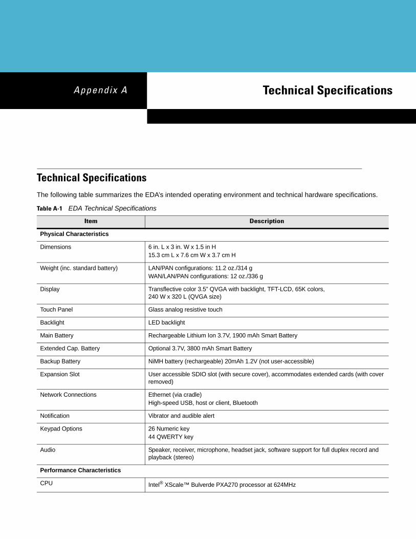
Appendix A Technical Specifications
Chapter A
Appendix A Technical SpecificationsTechnical SpecificationsThe following table summarizes the EDA’s intended operating environment and technical hardware specifications.
Table A-1 EDA Technical Specifications
Item Description
Physical Characteristics
Dimensions 6 in. L x 3 in. W x 1.5 in H 15.3 cm L x 7.6 cm W x 3.7 cm H
Weight (inc. standard battery) LAN/PAN configurations: 11.2 oz./314 g WAN/LAN/PAN configurations: 12 oz./336 g
Display Transflective color 3.5” QVGA with backlight, TFT-LCD, 65K colors, 240 W x 320 L (QVGA size)
Touch Panel Glass analog resistive touch
Backlight LED backlight
Main Battery Rechargeable Lithium Ion 3.7V, 1900 mAh Smart Battery
Extended Cap. Battery Optional 3.7V, 3800 mAh Smart Battery
Backup Battery NiMH battery (rechargeable) 20mAh 1.2V (not user-accessible)
Expansion Slot User accessible SDIO slot (with secure cover), accommodates extended cards (with cover removed)
Network Connections Ethernet (via cradle)High-speed USB, host or client, Bluetooth
Notification Vibrator and audible alert
Keypad Options 26 Numeric key44 QWERTY key
Audio Speaker, receiver, microphone, headset jack, software support for full duplex record and playback (stereo)
Performance Characteristics
CPU Intel® XScale™ Bulverde PXA270 processor at 624MHz
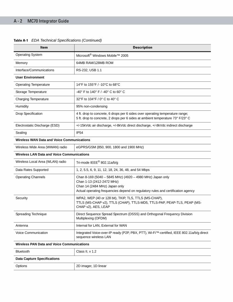
A - 2 MC70 Integrator Guide
Operating System Microsoft® Windows Mobile™ 2005
Memory 64MB RAM/128MB ROM
Interface/Communications RS-232, USB 1.1
User Environment
Operating Temperature 14°F to 155°F / -10°C to 68°C
Storage Temperature -40° F to 140° F / -40° C to 60° C
Charging Temperature 32°F to 104°F / 0° C to 40° C
Humidity 95% non-condensing
Drop Specification 4 ft. drop to concrete, 6 drops per 6 sides over operating temperature range; 5 ft. drop to concrete, 2 drops per 6 sides at ambient temperature 73° F/23° C
Electrostatic Discharge (ESD) +/-15kVdc air discharge, +/-8kVdc direct discharge, +/-8kVdc indirect discharge
Sealing IP54
Wireless WAN Data and Voice Communications
Wireless Wide Area (WWAN) radio eGPRS/GSM (850, 900, 1800 and 1900 MHz)
Wireless LAN Data and Voice Communications
Wireless Local Area (WLAN) radio Tri-mode IEEE® 802.11a/b/g
Data Rates Supported 1, 2, 5.5, 6, 9, 11, 12, 18, 24, 36, 48, and 54 Mbps
Operating Channels Chan 8-169 (5040 – 5845 MHz) (4920 – 4980 MHz) Japan only Chan 1-13 (2412-2472 MHz) Chan 14 (2484 MHz) Japan only Actual operating frequencies depend on regulatory rules and certification agency
Security WPA2, WEP (40 or 128 bit), TKIP, TLS, TTLS (MS-CHAP), TTLS (MS-CHAP v2), TTLS (CHAP), TTLS-MD5, TTLS-PAP, PEAP-TLS, PEAP (MS-CHAP v2), AES, LEAP
Spreading Technique Direct Sequence Spread Spectrum (DSSS) and Orthogonal Frequency Division Multiplexing (OFDM)
Antenna Internal for LAN, External for WAN
Voice Communication Integrated Voice-over-IP ready (P2P, PBX, PTT), Wi-Fi™-certified, IEEE 802.11a/b/g direct sequence wireless LAN
Wireless PAN Data and Voice Communications
Bluetooth Class II, v 1.2
Data Capture Specifications
Options 2D imager, 1D linear
Table A-1 EDA Technical Specifications (Continued)
Item Description
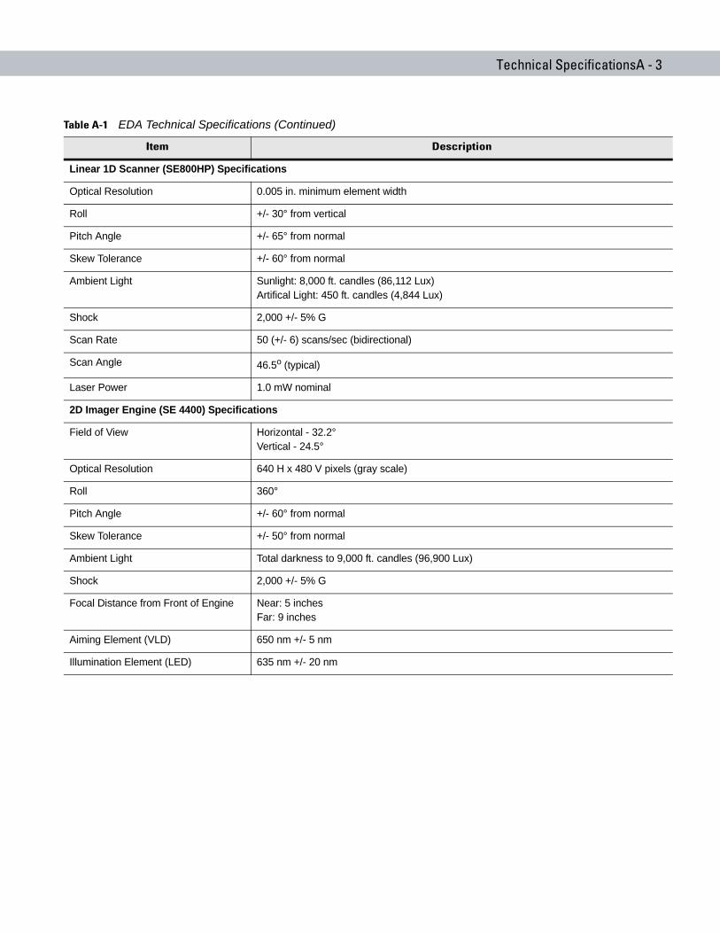
Technical SpecificationsA - 3
Linear 1D Scanner (SE800HP) Specifications
Optical Resolution 0.005 in. minimum element width
Roll +/- 30° from vertical
Pitch Angle +/- 65° from normal
Skew Tolerance +/- 60° from normal
Ambient Light Sunlight: 8,000 ft. candles (86,112 Lux)Artifical Light: 450 ft. candles (4,844 Lux)
Shock 2,000 +/- 5% G
Scan Rate 50 (+/- 6) scans/sec (bidirectional)
Scan Angle 46.5o (typical)
Laser Power 1.0 mW nominal
2D Imager Engine (SE 4400) Specifications
Field of View Horizontal - 32.2°Vertical - 24.5°
Optical Resolution 640 H x 480 V pixels (gray scale)
Roll 360°
Pitch Angle +/- 60° from normal
Skew Tolerance +/- 50° from normal
Ambient Light Total darkness to 9,000 ft. candles (96,900 Lux)
Shock 2,000 +/- 5% G
Focal Distance from Front of Engine Near: 5 inchesFar: 9 inches
Aiming Element (VLD) 650 nm +/- 5 nm
Illumination Element (LED) 635 nm +/- 20 nm
Table A-1 EDA Technical Specifications (Continued)
Item Description
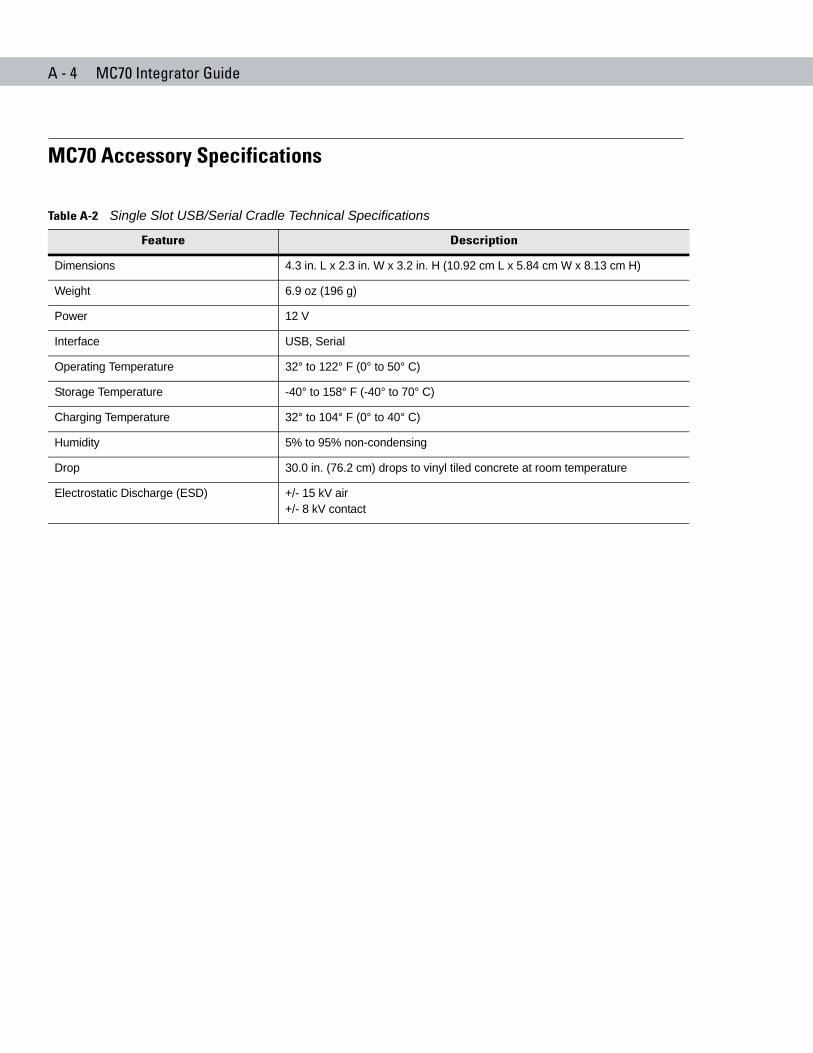
A - 4 MC70 Integrator Guide
MC70 Accessory Specifications
Table A-2 Single Slot USB/Serial Cradle Technical Specifications
Feature Description
Dimensions 4.3 in. L x 2.3 in. W x 3.2 in. H (10.92 cm L x 5.84 cm W x 8.13 cm H)
Weight 6.9 oz (196 g)
Power 12 V
Interface USB, Serial
Operating Temperature 32° to 122° F (0° to 50° C)
Storage Temperature -40° to 158° F (-40° to 70° C)
Charging Temperature 32° to 104° F (0° to 40° C)
Humidity 5% to 95% non-condensing
Drop 30.0 in. (76.2 cm) drops to vinyl tiled concrete at room temperature
Electrostatic Discharge (ESD) +/- 15 kV air+/- 8 kV contact
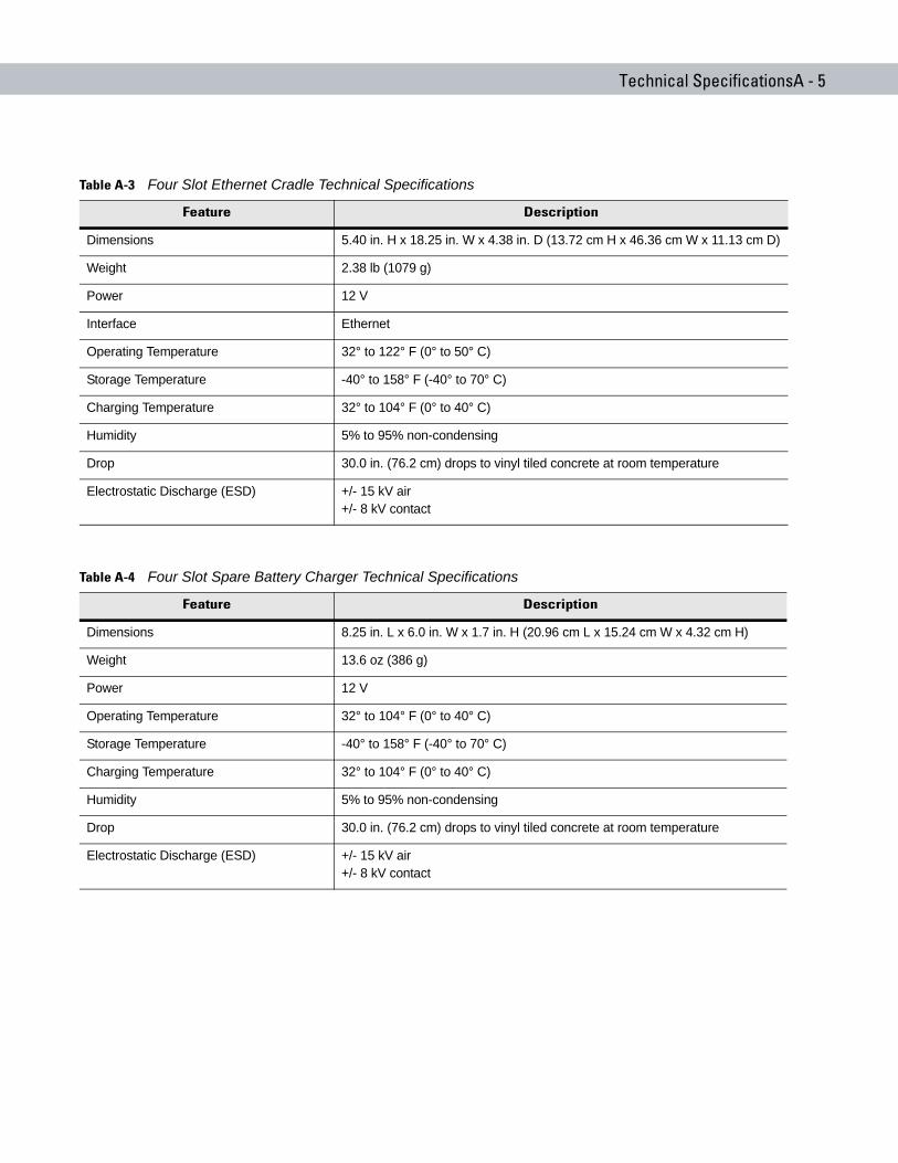
Technical SpecificationsA - 5
Table A-3 Four Slot Ethernet Cradle Technical Specifications
Feature Description
Dimensions 5.40 in. H x 18.25 in. W x 4.38 in. D (13.72 cm H x 46.36 cm W x 11.13 cm D)
Weight 2.38 lb (1079 g)
Power 12 V
Interface Ethernet
Operating Temperature 32° to 122° F (0° to 50° C)
Storage Temperature -40° to 158° F (-40° to 70° C)
Charging Temperature 32° to 104° F (0° to 40° C)
Humidity 5% to 95% non-condensing
Drop 30.0 in. (76.2 cm) drops to vinyl tiled concrete at room temperature
Electrostatic Discharge (ESD) +/- 15 kV air+/- 8 kV contact
Table A-4 Four Slot Spare Battery Charger Technical Specifications
Feature Description
Dimensions 8.25 in. L x 6.0 in. W x 1.7 in. H (20.96 cm L x 15.24 cm W x 4.32 cm H)
Weight 13.6 oz (386 g)
Power 12 V
Operating Temperature 32° to 104° F (0° to 40° C)
Storage Temperature -40° to 158° F (-40° to 70° C)
Charging Temperature 32° to 104° F (0° to 40° C)
Humidity 5% to 95% non-condensing
Drop 30.0 in. (76.2 cm) drops to vinyl tiled concrete at room temperature
Electrostatic Discharge (ESD) +/- 15 kV air+/- 8 kV contact
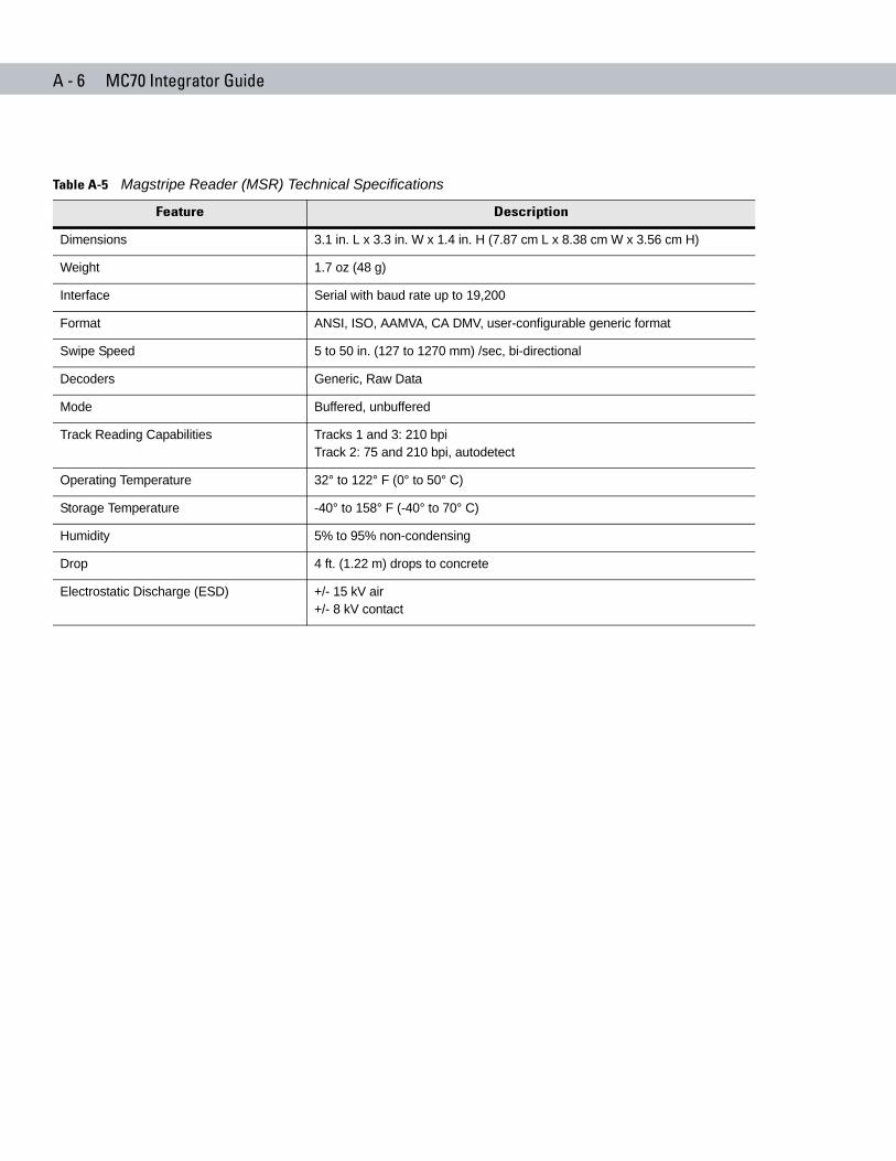
A - 6 MC70 Integrator Guide
Table A-5 Magstripe Reader (MSR) Technical Specifications
Feature Description
Dimensions 3.1 in. L x 3.3 in. W x 1.4 in. H (7.87 cm L x 8.38 cm W x 3.56 cm H)
Weight 1.7 oz (48 g)
Interface Serial with baud rate up to 19,200
Format ANSI, ISO, AAMVA, CA DMV, user-configurable generic format
Swipe Speed 5 to 50 in. (127 to 1270 mm) /sec, bi-directional
Decoders Generic, Raw Data
Mode Buffered, unbuffered
Track Reading Capabilities Tracks 1 and 3: 210 bpiTrack 2: 75 and 210 bpi, autodetect
Operating Temperature 32° to 122° F (0° to 50° C)
Storage Temperature -40° to 158° F (-40° to 70° C)
Humidity 5% to 95% non-condensing
Drop 4 ft. (1.22 m) drops to concrete
Electrostatic Discharge (ESD) +/- 15 kV air+/- 8 kV contact
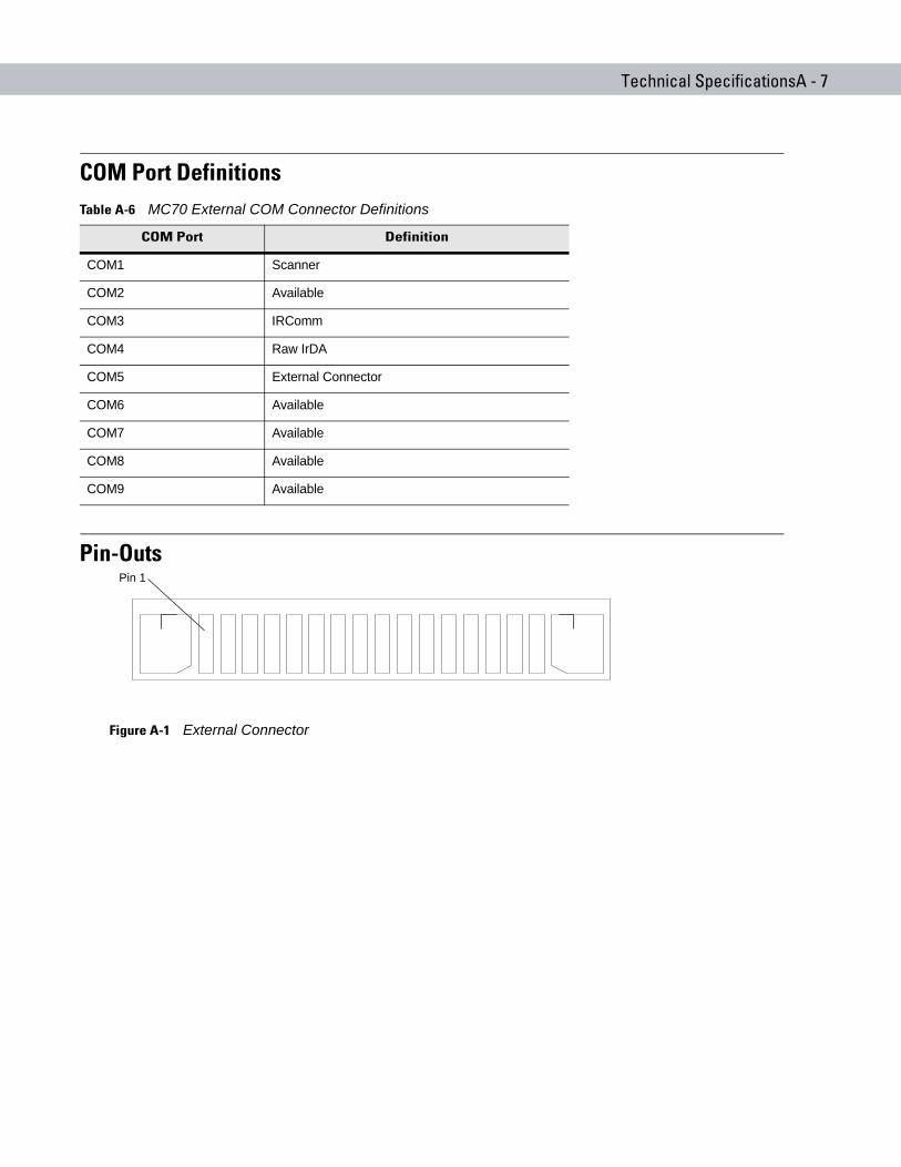
Technical SpecificationsA - 7
COM Port Definitions
Pin-Outs
Figure A-1 External Connector
Table A-6 MC70 External COM Connector Definitions
COM Port Definition
COM1 Scanner
COM2 Available
COM3 IRComm
COM4 Raw IrDA
COM5 External Connector
COM6 Available
COM7 Available
COM8 Available
COM9 Available
Pin 1
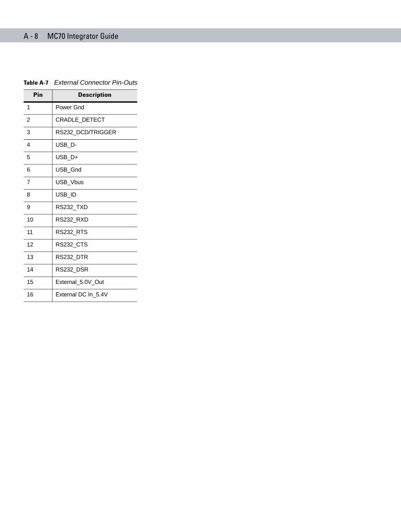
A - 8 MC70 Integrator Guide
Table A-7 External Connector Pin-Outs
Pin Description
1 Power Gnd
2 CRADLE_DETECT
3 RS232_DCD/TRIGGER
4 USB_D-
5 USB_D+
6 USB_Gnd
7 USB_Vbus
8 USB_ID
9 RS232_TXD
10 RS232_RXD
11 RS232_RTS
12 RS232_CTS
13 RS232_DTR
14 RS232_DSR
15 External_5.0V_Out
16 External DC In_5.4V
Glossary
AAPI. An interface by means of which one software component communicates with or controls another. Usually used to
refer to services provided by one software component to another, usually via software interrupts or function calls
Aperture. The opening in an optical system defined by a lens or baffle that establishes the field of view.
Application Programming Interface. See API.
ANSI Terminal. A display terminal that follows commands in the ANSI standard terminal language. For example, it uses escape sequences to control the cursor, clear the screen and set colors. Communications programs support the ANSI terminal mode and often default to this terminal emulation for dial-up connections to online services.
ASCII. American Standard Code for Information Interchange. A 7 bit-plus-parity code representing 128 letters, numerals, punctuation marks and control characters. It is a standard data transmission code in the U.S.
Autodiscrimination. The ability of an interface controller to determine the code type of a scanned bar code. After this determination is made, the information content is decoded.
BBar. The dark element in a printed bar code symbol.
Bar Code. A pattern of variable-width bars and spaces which represents numeric or alphanumeric data in machine-readable form. The general format of a bar code symbol consists of a leading margin, start character, data or message character, check character (if any), stop character, and trailing margin. Within this framework, each recognizable symbology uses its own unique format. See Symbology.
Bar Code Density. The number of characters represented per unit of measurement (e.g., characters per inch).
Bar Height. The dimension of a bar measured perpendicular to the bar width.
Bar Width. Thickness of a bar measured from the edge closest to the symbol start character to the trailing edge of the same bar.
BIOS. Basic Input Output System. A collection of ROM-based code with a standard API used to interface with standard PC hardware.
Glossary - 2 MC70 Integrator Guide
Bit. Binary digit. One bit is the basic unit of binary information. Generally, eight consecutive bits compose one byte of data. The pattern of 0 and 1 values within the byte determines its meaning.
Bits per Second (bps). Bits transmitted or received.
BOOTP. A protocol for remote booting of diskless devices. Assigns an IP address to a machine and may specify a boot file. The client sends a bootp request as a broadcast to the bootp server port (67) and the bootp server responds using the bootp client port (68). The bootp server must have a table of all devices, associated MAC addresses and IP addresses.
boot or boot-up. The process a computer goes through when it starts. During boot-up, the computer can run self-diagnostic tests and configure hardware and software.
bps. See Bits Per Second.
Byte. On an addressable boundary, eight adjacent binary digits (0 and 1) combined in a pattern to represent a specific character or numeric value. Bits are numbered from the right, 0 through 7, with bit 0 the low-order bit. One byte in memory is used to store one ASCII character.
CCDRH. Center for Devices and Radiological Health. A federal agency responsible for regulating laser product safety.
This agency specifies various laser operation classes based on power output during operation.
CDRH Class 1. This is the lowest power CDRH laser classification. This class is considered intrinsically safe, even if all laser output were directed into the eye's pupil. There are no special operating procedures for this class.
CDRH Class 2. No additional software mechanisms are needed to conform to this limit. Laser operation in this class poses no danger for unintentional direct human exposure.
Character. A pattern of bars and spaces which either directly represents data or indicates a control function, such as a number, letter, punctuation mark, or communications control contained in a message.
Character Set. Those characters available for encoding in a particular bar code symbology.
Check Digit. A digit used to verify a correct symbol decode. The scanner inserts the decoded data into an arithmetic formula and checks that the resulting number matches the encoded check digit. Check digits are required for UPC but are optional for other symbologies. Using check digits decreases the chance of substitution errors when a symbol is decoded.
Codabar. A discrete self-checking code with a character set consisting of digits 0 to 9 and six additional characters: ( - $ : / , +).
Code 128. A high density symbology which allows the controller to encode all 128 ASCII characters without adding extra symbol elements.
Code 3 of 9 (Code 39). A versatile and widely used alphanumeric bar code symbology with a set of 43 character types, including all uppercase letters, numerals from 0 to 9 and 7 special characters (- . / + % $ and space). The code name is derived from the fact that 3 of 9 elements representing a character are wide, while the remaining 6 are narrow.
Glossary - 3
Code 93. An industrial symbology compatible with Code 39 but offering a full character ASCII set and a higher coding density than Code 39.
Code Length. Number of data characters in a bar code between the start and stop characters, not including those characters.
Cold Boot. A cold boot restarts the mobile computer and erases all user stored records and entries.
COM port. Communication port; ports are identified by number, e.g., COM1, COM2.
Continuous Code. A bar code or symbol in which all spaces within the symbol are parts of characters. There are no intercharacter gaps in a continuous code. The absence of gaps allows for greater information density.
Cradle. A cradle is used for charging the terminal battery and for communicating with a host computer, and provides a storage place for the terminal when not in use.
DData Communications Equipment (DCE). A device (such as a modem) which is designed to attach directly to a DTE
(Data Terminal Equipment) device.
DCE. See Data Communications Equipment.
DCP. See Device Configuration Package.
Dead Zone. An area within a scanner's field of view, in which specular reflection may prevent a successful decode.
Decode. To recognize a bar code symbology (e.g., UPC/EAN) and then analyze the content of the specific bar code scanned.
Decode Algorithm. A decoding scheme that converts pulse widths into data representation of the letters or numbers encoded within a bar code symbol.
Decryption. Decryption is the decoding and unscrambling of received encrypted data. Also see, Encryption and Key.
Depth of Field. The range between minimum and maximum distances at which a scanner can read a symbol with a certain minimum element width.
Device Configuration Package. The Symbol Device Configuration Package provides the Product Reference Guide (PRG), flash partitions, Terminal Configuration Manager (TCM) and the associated TCM scripts. With this package hex images that represent flash partitions can be created and downloaded to the mobile computer.
Discrete Code. A bar code or symbol in which the spaces between characters (intercharacter gaps) are not part of the code.
Discrete 2 of 5. A binary bar code symbology representing each character by a group of five bars, two of which are wide. The location of wide bars in the group determines which character is encoded; spaces are insignificant. Only numeric characters (0 to 9) and START/STOP characters may be encoded.
DRAM. Dynamic random access memory.

Glossary - 4 MC70 Integrator Guide
DTE. See Data Terminal Equipment.
EEAN. European Article Number. This European/International version of the UPC provides its own coding format and
symbology standards. Element dimensions are specified metrically. EAN is used primarily in retail.
Element. Generic term for a bar or space.
Encoded Area. Total linear dimension occupied by all characters of a code pattern, including start/stop characters and data.
ENQ (RS-232). ENQ software handshaking is also supported for the data sent to the host.
ESD. Electro-Static Discharge
FFile Transfer Protocol (FTP). A TCP/IP application protocol governing file transfer via network or telephone lines. See
TCP/IP.
Flash Disk. An additional megabyte of non-volatile memory for storing application and configuration files.
Flash Memory. Flash memory is nonvolatile, semi-permanent storage that can be electronically erased in the circuit and reprogrammed. Series 9000 mobile computers use Flash memory to store the operating system (ROM-DOS), the terminal emulators, and the Citrix ICA Client for DOS.
FTP. See File Transfer Protocol.
HHard Reset. See Cold Boot.
Hz. Hertz; A unit of frequency equal to one cycle per second.
Host Computer. A computer that serves other terminals in a network, providing such services as computation, database access, supervisory programs and network control.
IIDE. Intelligent drive electronics. Refers to the solid-state hard drive type.

Glossary - 5
IEC. International Electrotechnical Commission. This international agency regulates laser safety by specifying various laser operation classes based on power output during operation.
IEC (825) Class 1. This is the lowest power IEC laser classification. Conformity is ensured through a software restriction of 120 seconds of laser operation within any 1000 second window and an automatic laser shutdown if the scanner's oscillating mirror fails.
IEEE Address. See MAC Address.
Input/Output Ports. I/O ports are primarily dedicated to passing information into or out of the terminal’s memory. Series 9000 mobile computers include Serial and USB ports.
Interleaved 2 of 5. A binary bar code symbology representing character pairs in groups of five bars and five interleaved spaces. Interleaving provides for greater information density. The location of wide elements (bar/spaces) within each group determines which characters are encoded. This continuous code type uses no intercharacter spaces. Only numeric (0 to 9) and START/STOP characters may be encoded.
Intercharacter Gap. The space between two adjacent bar code characters in a discrete code.
Interleaved Bar Code. A bar code in which characters are paired together, using bars to represent the first character and the intervening spaces to represent the second.
Internet Protocol Address. See IP.
IOCTL. Input/Output Control.
I/O Ports. interface The connection between two devices, defined by common physical characteristics, signal characteristics, and signal meanings. Types of interfaces include RS-232 and PCMCIA.
IP. Internet Protocol. The IP part of the TCP/IP communications protocol. IP implements the network layer (layer 3) of the protocol, which contains a network address and is used to route a message to a different network or subnetwork. IP accepts “packets” from the layer 4 transport protocol (TCP or UDP), adds its own header to it and delivers a “datagram” to the layer 2 data link protocol. It may also break the packet into fragments to support the maximum transmission unit (MTU) of the network.
IP Address. (Internet Protocol address) The address of a computer attached to an IP network. Every client and server station must have a unique IP address. A 32-bit address used by a computer on a IP network. Client workstations have either a permanent address or one that is dynamically assigned to them each session. IP addresses are written as four sets of numbers separated by periods; for example, 204.171.64.2.
IPX/SPX. Internet Package Exchange/Sequential Packet Exchange. A communications protocol for Novell. IPX is Novell’s Layer 3 protocol, similar to XNS and IP, and used in NetWare networks. SPX is Novell's version of the Xerox SPP protocol.
IS-95. Interim Standard 95. The EIA/TIA standard that governs the operation of CDMA cellular service. Versions include IS-95A and IS-95B. See CDMA.
Glossary - 6 MC70 Integrator Guide
KKey. A key is the specific code used by the algorithm to encrypt or decrypt the data. Also see, Encryption and
Decrypting.
LLASER. Light Amplification by Stimulated Emission of Radiation.The laser is an intense light source. Light from a laser
is all the same frequency, unlike the output of an incandescent bulb. Laser light is typically coherent and has a high energy density.
Laser Diode. A gallium-arsenide semiconductor type of laser connected to a power source to generate a laser beam. This laser type is a compact source of coherent light.
laser scanner. A type of bar code reader that uses a beam of laser light.
LCD. See Liquid Crystal Display.
LED Indicator. A semiconductor diode (LED - Light Emitting Diode) used as an indicator, often in digital displays. The semiconductor uses applied voltage to produce light of a certain frequency determined by the semiconductor's particular chemical composition.
Light Emitting Diode. See LED.
Liquid Crystal Display (LCD). A display that uses liquid crystal sealed between two glass plates. The crystals are excited by precise electrical charges, causing them to reflect light outside according to their bias. They use little electricity and react relatively quickly. They require external light to reflect their information to the user.
MMC. Mobile Computer.
MDN. Mobile Directory Number. The directory listing telephone number that is dialed (generally using POTS) to reach a mobile unit. The MDN is usually associated with a MIN in a cellular telephone -- in the US and Canada, the MDN and MIN are the same value for voice cellular users. International roaming considerations often result in the MDN being different from the MIN.
MIL. 1 mil = 1 thousandth of an inch.
MIN. Mobile Identification Number. The unique account number associated with a cellular device. It is broadcast by the cellular device when accessing the cellular system.
Misread (Misdecode). A condition which occurs when the data output of a reader or interface controller does not agree with the data encoded within a bar code symbol.
Glossary - 7
Mobile Computer. In this text, mobile computer refers to the Symbol Series 9000 wireless portable computer. It can be set up to run as a stand-alone device, or it can be set up to communicate with a network, using wireless radio technology.
NNominal. The exact (or ideal) intended value for a specified parameter. Tolerances are specified as positive and
negative deviations from this value.
Nominal Size. Standard size for a bar code symbol. Most UPC/EAN codes are used over a range of magnifications (e.g., from 0.80 to 2.00 of nominal).
NVM. Non-Volatile Memory.
OODI. See Open Data-Link Interface.
Open Data-Link Interface (ODI). Novell’s driver specification for an interface between network hardware and higher-level protocols. It supports multiple protocols on a single NIC (Network Interface Controller). It is capable of understanding and translating any network information or request sent by any other ODI-compatible protocol into something a NetWare client can understand and process.
Open System Authentication. Open System authentication is a null authentication algorithm.
PPAN . Personal area network. Using Bluetooth wireless technology, PANs enable devices to communicate wirelessly.
Generally, a wireless PAN consists of a dynamic group of less than 255 devices that communicate within about a 33-foot range. Only devices within this limited area typically participate in the network.
Parameter. A variable that can have different values assigned to it.
PC Card. A plug-in expansion card for laptop computers and other devices, also called a PCMCIA card. PC Cards are 85.6mm long x 54 mm wide, and have a 68 pin connector. There are several different kinds:
Type I; 3.3 mm high; use - RAM or Flash RAM
Type II; 5 mm high; use - modems, LAN adaptors
Type III; 10.5 high; use - Hard Disks
PCMCIA. Personal Computer Memory Card Interface Association. See PC Card.
Glossary - 8 MC70 Integrator Guide
Percent Decode. The average probability that a single scan of a bar code would result in a successful decode. In a well-designed bar code scanning system, that probability should approach near 100%.
PING. (Packet Internet Groper) An Internet utility used to determine whether a particular IP address is online. It is used to test and debug a network by sending out a packet and waiting for a response.
Print Contrast Signal (PCS). Measurement of the contrast (brightness difference) between the bars and spaces of a symbol. A minimum PCS value is needed for a bar code symbol to be scannable. PCS = (RL - RD) / RL, where RL is the reflectance factor of the background and RD the reflectance factor of the dark bars.
Programming Mode. The state in which a scanner is configured for parameter values. See Scanning Mode.
QQuiet Zone. A clear space, containing no dark marks, which precedes the start character of a bar code symbol and
follows the stop character.
QWERTY. A standard keyboard commonly used on North American and some European PC keyboards. “QWERTY” refers to the arrangement of keys on the left side of the third row of keys.
RRAM. Random Access Memory. Data in RAM can be accessed in random order, and quickly written and read.
Reflectance. Amount of light returned from an illuminated surface.
Resolution. The narrowest element dimension which is distinguished by a particular reading device or printed with a particular device or method.
RF. Radio Frequency.
ROM. Read-Only Memory. Data stored in ROM cannot be changed or removed.
Router. A device that connects networks and supports the required protocols for packet filtering. Routers are typically used to extend the range of cabling and to organize the topology of a network into subnets. See Subnet.
RS-232. An Electronic Industries Association (EIA) standard that defines the connector, connector pins, and signals used to transfer data serially from one device to another.
SScan Area. Area intended to contain a symbol.
Glossary - 9
Scanner. An electronic device used to scan bar code symbols and produce a digitized pattern that corresponds to the bars and spaces of the symbol. Its three main components are: 1) Light source (laser or photoelectric cell) - illuminates a bar code,; 2) Photodetector - registers the difference in reflected light (more light reflected from spaces); 3) Signal conditioning circuit - transforms optical detector output into a digitized bar pattern.
Scanning Mode. The scanner is energized, programmed and ready to read a bar code.
Scanning Sequence. A method of programming or configuring parameters for a bar code reading system by scanning bar code menus.
SDK. Software Development Kit
Self-Checking Code. A symbology that uses a checking algorithm to detect encoding errors within the characters of a bar code symbol.
Shared Key. Shared Key authentication is an algorithm where both the AP and the MU share an authentication key.
SHIP. Symbol Host Interface Program.
SID. System Identification code. An identifier issued by the FCC for each market. It is also broadcast by the cellular carriers to allow cellular devices to distinguish between the home and roaming service.
SMDK. Symbol Mobility Developer’s Kit.
Soft Reset. See Warm Boot.
Space. The lighter element of a bar code formed by the background between bars.
Specular Reflection. The mirror-like direct reflection of light from a surface, which can cause difficulty decoding a bar code.
Start/Stop Character. A pattern of bars and spaces that provides the scanner with start and stop reading instructions and scanning direction. The start and stop characters are normally to the left and right margins of a horizontal code.
STEP. Symbol Terminal Enabler Program.
Subnet. A subset of nodes on a network that are serviced by the same router. See Router.
Subnet Mask. A 32-bit number used to separate the network and host sections of an IP address. A custom subnet mask subdivides an IP network into smaller subsections. The mask is a binary pattern that is matched up with the IP address to turn part of the host ID address field into a field for subnets. Default is often 255.255.255.0.
Substrate. A foundation material on which a substance or image is placed.
SVTP. Symbol Virtual Terminal Program.
Symbol. A scannable unit that encodes data within the conventions of a certain symbology, usually including start/stop characters, quiet zones, data characters and check characters.
Symbol Aspect Ratio. The ratio of symbol height to symbol width.
Symbol Height. The distance between the outside edges of the quiet zones of the first row and the last row.

Glossary - 10 MC70 Integrator Guide
Symbol Length. Length of symbol measured from the beginning of the quiet zone (margin) adjacent to the start character to the end of the quiet zone (margin) adjacent to a stop character.
Symbology. The structural rules and conventions for representing data within a particular bar code type (e.g. UPC/EAN, Code 39, PDF417, etc.).
TTCP/IP. (Transmission Control Protocol/Internet Protocol) A communications protocol used to internetwork dissimilar
systems. This standard is the protocol of the Internet and has become the global standard for communications. TCP provides transport functions, which ensures that the total amount of bytes sent is received correctly at the other end. UDP is an alternate transport that does not guarantee delivery. It is widely used for real-time voice and video transmissions where erroneous packets are not retransmitted. IP provides the routing mechanism. TCP/IP is a routable protocol, which means that all messages contain not only the address of the destination station, but the address of a destination network. This allows TCP/IP messages to be sent to multiple networks within an organization or around the world, hence its use in the worldwide Internet. Every client and server in a TCP/IP network requires an IP address, which is either permanently assigned or dynamically assigned at startup.
Telnet. A terminal emulation protocol commonly used on the Internet and TCP/IP-based networks. It allows a user at a terminal or computer to log onto a remote device and run a program.
Terminal. See Mobile Computer.
Terminal Emulation. A “terminal emulation” emulates a character-based mainframe session on a remote non-mainframe terminal, including all display features, commands and function keys. The VC5000 Series supports Terminal Emulations in 3270, 5250 and VT220.
Terminate and Stay Resident (TSR). A program under DOS that ends its foreground execution to remain resident in memory to service hardware/software interrupts, providing background operation. It remains in memory and may provide services on behalf of other DOS programs.
TFTP. (Trivial File Transfer Protocol) A version of the TCP/IP FTP (File Transfer Protocol) protocol that has no directory or password capability. It is the protocol used for upgrading firmware, downloading software and remote booting of diskless devices.
Tolerance. Allowable deviation from the nominal bar or space width.
Transmission Control Protocol/Internet Protocol. See TCP/IP.
Trivial File Transfer Protocol. See TFTP.
TSR. See Terminate and Stay Resident.
UUDP. User Datagram Protocol. A protocol within the IP protocol suite that is used in place of TCP when a reliable
delivery is not required. For example, UDP is used for real-time audio and video traffic where lost packets are simply
Glossary - 11
ignored, because there is no time to retransmit. If UDP is used and a reliable delivery is required, packet sequence checking and error notification must be written into the applications.
UPC. Universal Product Code. A relatively complex numeric symbology. Each character consists of two bars and two spaces, each of which is any of four widths. The standard symbology for retail food packages in the United States.
VVisible Laser Diode (VLD). A solid state device which produces visible laser light.
WWarm Boot. A warm boot restarts the mobile computer by closing all running programs. All data that is not saved to
flash memory is lost.

Glossary - 12 MC70 Integrator Guide
Index
Numerics802.11 ESSID . . . . . . . . . . . . . . . . . . . . . . . . . . . . . . 6-5
Aaccessories . . . . . . . . . . . . . . . . . . . . . . . . . . . . . . . . 1-2
auto charge cable . . . . . . . . . . . . . . . . . . . . . . . . 1-2cables . . . . . . . . . . . . . . . . . . . . . . . . . . . . . 1-2, 2-26communication/charge cables . . . . . . . . . . . . . 2-27
battery charging . . . . . . . . . . . . . . . . . . . . . 2-28LED indicators . . . . . . . . . . . . . . . . . . . . . . 2-28
cradle . . . . . . . . . . . . . . . . . . . . . . . . . . . . . . . . . 2-1DEX cable . . . . . . . . . . . . . . . . . . . . . . . . . . . . . . 1-2four slot Ethernet cradle . . . . . . . . . . . . 1-2, 2-1, 2-6four slot spare battery charger . . . . . . 1-2, 2-1, 2-20headset . . . . . . . . . . . . . . . . . . . . . . . . . 1-2, 2-1, 2-2holster, quick release . . . . . . . . . . . . . . . . . . . . . 1-2magnetic stripe reader . . . . . . . . . . . . . . . . . 1-2, 2-2MMC . . . . . . . . . . . . . . . . . . . . . . . . . . . . . . . 2-1, 2-2mounting bracket . . . . . . . . . . . . . . . . . . . . . . . 2-10MSR . . . . . . . . . . . . . . . . . . . . . . . . . . . . . . . . . 2-22
installation . . . . . . . . . . . . . . . . . . . . . . . . . 2-22magnetic stripe reading . . . . . . . . . . . . . . . 2-23
multi media card . . . . . . . . . . . . . . . . . . . . . . . . . 1-2printer cable . . . . . . . . . . . . . . . . . . . . . . . . . . . . 1-2rigid case . . . . . . . . . . . . . . . . . . . . . . . . . . . . . . 2-1SD card . . . . . . . . . . . . . . . . . . . . . . . . . . . . . 2-1, 2-2shelf slide . . . . . . . . . . . . . . . . . . . . . . . . . . . . . . 1-2SIM card . . . . . . . . . . . . . . . . . . . . . . . . . . . . . . . 1-9single slot USB serial cradle . . . . . . . . . . . . . . . . 2-3SMDK . . . . . . . . . . . . . . . . . . . . . . . . . . . . . . . . . 1-2snap on cable . . . . . . . . . . . . . . . . . . . . . . . . . . . 1-2snap-on handle . . . . . . . . . . . . . . . . . . . . . . . . . . 1-2spare battery . . . . . . . . . . . . . . . . . . . . . . . . . . . . 1-2specifications . . . . . . . . . . . . . . . . . . . . . . . . . . . A-4stylus . . . . . . . . . . . . . . . . . . . . . . . . . . . . . . . . . 1-2trigger handle . . . . . . . . . . . . . . . . . . . . . . . 2-2, 2-23USB cable . . . . . . . . . . . . . . . . . . . . . . . . . . . . . . 1-2USB charger cable . . . . . . . . . . . . . . . . . . . . . . . 1-2USB cradle . . . . . . . . . . . . . . . . . . . . . . . . . . . . . 1-2
vehicle cradle . . . . . . . . . . . . . . . . . . . 1-2, 2-1, 2-12wall mounting kit, cradle . . . . . . . . . . . . . . . . . . . 1-2
ActiveSync . . . . . . . . . . . . . . . . . . . . . . . . . . . . . . . . . 3-1deploying CAB files . . . . . . . . . . . . . . . . . . . . . . . 4-4installing . . . . . . . . . . . . . . . . . . . . . . . . . . . . . . . 3-2setting up a connection . . . . . . . . . . . . . . . . . . . . 3-3
ad-hoc . . . . . . . . . . . . . . . . . . . . . . . . . . . . . . . . . . . . 6-6ad-hoc networks . . . . . . . . . . . . . . . . . . . . . . . . . . . . 6-34AirBEAM
AirBEAM Smart . . . . . . . . . . . . . . . . . . . . . . . . . 4-16Client . . . . . . . . . . . . . . . . . . . . . . . . . . . . . . . . . 4-17configuring . . . . . . . . . . . . . . . . . . . . . . . . . . . . . 4-17deploying CAB files . . . . . . . . . . . . . . . . . . . . . . . 4-5license . . . . . . . . . . . . . . . . . . . . . . . . . . . . . . . . 4-17package builder . . . . . . . . . . . . . . . . . . . . . . . . . 4-16rapid deployment . . . . . . . . . . . . . . . . . . . . . . . . 4-14staging . . . . . . . . . . . . . . . . . . . . . . . . . . . . . . . . 4-24synchronization with server . . . . . . . . . . . . . . . . 4-23
AP networks . . . . . . . . . . . . . . . . . . . . . . . . . . . . . . . 6-34APN . . . . . . . . . . . . . . . . . . . . . . . . . . . . . . . . . . . . . . 5-4application deployment . . . . . . . . . . . . . . . . . . . 4-1, 4-4
CAB files . . . . . . . . . . . . . . . . . . . . . . . . . . . . . . . 4-4application folder . . . . . . . . . . . . . . . . . . . . . . . . . . . 4-10application packaging . . . . . . . . . . . . . . . . . . . . . . . . 4-4application security . . . . . . . . . . . . . . . . . . . . . . . . . . 4-1authentication
EAP-TLS . . . . . . . . . . . . . . . . . . . . . . . . . . . . . . . 6-7LEAP . . . . . . . . . . . . . . . . . . . . . . . . . . . . . . . . . . 6-8none . . . . . . . . . . . . . . . . . . . . . . . . . . . . . . . . . . 6-7PEAP . . . . . . . . . . . . . . . . . . . . . . . . . . . . . . . . . . 6-8
auto charge cable . . . . . . . . . . . . . . . . . . . . . . . . . . . 1-2
Bbackup battery
charging . . . . . . . . . . . . . . . . . . . . . . . . . . . . . . . . 1-5battery
backup charging . . . . . . . . . . . . . . . . . . . . . . . . . 1-5charging . . . . . . . . . . . . . . . . . . . . . . . . . . . . . . . . 1-5charging main battery . . . . . . . . . . . . . . . . . . . . . 1-5installing . . . . . . . . . . . . . . . . . . . . . . . . . . . . . . . 1-3
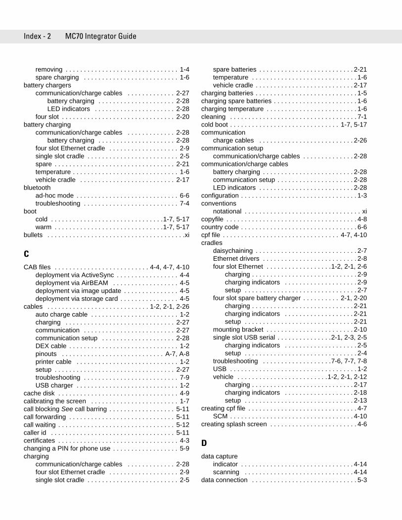
Index - 2 MC70 Integrator Guide
removing . . . . . . . . . . . . . . . . . . . . . . . . . . . . . . . 1-4spare charging . . . . . . . . . . . . . . . . . . . . . . . . . . 1-6
battery chargerscommunication/charge cables . . . . . . . . . . . . . 2-27
battery charging . . . . . . . . . . . . . . . . . . . . . 2-28LED indicators . . . . . . . . . . . . . . . . . . . . . . 2-28
four slot . . . . . . . . . . . . . . . . . . . . . . . . . . . . . . . 2-20battery charging
communication/charge cables . . . . . . . . . . . . . 2-28battery charging . . . . . . . . . . . . . . . . . . . . . 2-28
four slot Ethernet cradle . . . . . . . . . . . . . . . . . . . 2-9single slot cradle . . . . . . . . . . . . . . . . . . . . . . . . . 2-5spare . . . . . . . . . . . . . . . . . . . . . . . . . . . . . . . . . 2-21temperature . . . . . . . . . . . . . . . . . . . . . . . . . . . . . 1-6vehicle cradle . . . . . . . . . . . . . . . . . . . . . . . . . . 2-17
bluetoothad-hoc mode . . . . . . . . . . . . . . . . . . . . . . . . . . . . 6-6troubleshooting . . . . . . . . . . . . . . . . . . . . . . . . . . 7-4
bootcold . . . . . . . . . . . . . . . . . . . . . . . . . . . . . . .1-7, 5-17warm . . . . . . . . . . . . . . . . . . . . . . . . . . . . . .1-7, 5-17
bullets . . . . . . . . . . . . . . . . . . . . . . . . . . . . . . . . . . . . . .xi
CCAB files . . . . . . . . . . . . . . . . . . . . . . . . . . 4-4, 4-7, 4-10
deployment via ActiveSync . . . . . . . . . . . . . . . . . 4-4deployment via AirBEAM . . . . . . . . . . . . . . . . . . 4-5deployment via image update . . . . . . . . . . . . . . . 4-5deployment via storage card . . . . . . . . . . . . . . . . 4-5
cables . . . . . . . . . . . . . . . . . . . . . . . . . . . . 1-2, 2-1, 2-26auto charge cable . . . . . . . . . . . . . . . . . . . . . . . . 1-2charging . . . . . . . . . . . . . . . . . . . . . . . . . . . . . . 2-27communication . . . . . . . . . . . . . . . . . . . . . . . . . 2-27communication setup . . . . . . . . . . . . . . . . . . . . 2-28DEX cable . . . . . . . . . . . . . . . . . . . . . . . . . . . . . . 1-2pinouts . . . . . . . . . . . . . . . . . . . . . . . . . . . . A-7, A-8printer cable . . . . . . . . . . . . . . . . . . . . . . . . . . . . 1-2setup . . . . . . . . . . . . . . . . . . . . . . . . . . . . . . . . . 2-27troubleshooting . . . . . . . . . . . . . . . . . . . . . . . . . . 7-9USB charger . . . . . . . . . . . . . . . . . . . . . . . . . . . . 1-2
cache disk . . . . . . . . . . . . . . . . . . . . . . . . . . . . . . . . . 4-9calibrating the screen . . . . . . . . . . . . . . . . . . . . . . . . 1-7call blocking See call barring . . . . . . . . . . . . . . . . . . 5-11call forwarding . . . . . . . . . . . . . . . . . . . . . . . . . . . . . 5-11call waiting . . . . . . . . . . . . . . . . . . . . . . . . . . . . . . . . 5-12caller id . . . . . . . . . . . . . . . . . . . . . . . . . . . . . . . . . . 5-11certificates . . . . . . . . . . . . . . . . . . . . . . . . . . . . . . . . . 4-3changing a PIN for phone use . . . . . . . . . . . . . . . . . . 5-9charging
communication/charge cables . . . . . . . . . . . . . 2-28four slot Ethernet cradle . . . . . . . . . . . . . . . . . . . 2-9single slot cradle . . . . . . . . . . . . . . . . . . . . . . . . . 2-5
spare batteries . . . . . . . . . . . . . . . . . . . . . . . . . . 2-21temperature . . . . . . . . . . . . . . . . . . . . . . . . . . . . . 1-6vehicle cradle . . . . . . . . . . . . . . . . . . . . . . . . . . . 2-17
charging batteries . . . . . . . . . . . . . . . . . . . . . . . . . . . . 1-5charging spare batteries . . . . . . . . . . . . . . . . . . . . . . . 1-6charging temperature . . . . . . . . . . . . . . . . . . . . . . . . . 1-6cleaning . . . . . . . . . . . . . . . . . . . . . . . . . . . . . . . . . . . 7-1cold boot . . . . . . . . . . . . . . . . . . . . . . . . . . . . . . 1-7, 5-17communication
charge cables . . . . . . . . . . . . . . . . . . . . . . . . . . 2-26communication setup
communication/charge cables . . . . . . . . . . . . . . 2-28communication/charge cables
battery charging . . . . . . . . . . . . . . . . . . . . . . . . . 2-28communication setup . . . . . . . . . . . . . . . . . . . . . 2-28LED indicators . . . . . . . . . . . . . . . . . . . . . . . . . . 2-28
configuration . . . . . . . . . . . . . . . . . . . . . . . . . . . . . . . . 1-3conventions
notational . . . . . . . . . . . . . . . . . . . . . . . . . . . . . . . . xicopyfile . . . . . . . . . . . . . . . . . . . . . . . . . . . . . . . . . . . . 4-8country code . . . . . . . . . . . . . . . . . . . . . . . . . . . . . . . . 6-6cpf file . . . . . . . . . . . . . . . . . . . . . . . . . . . . . . . . 4-7, 4-10cradles
daisychaining . . . . . . . . . . . . . . . . . . . . . . . . . . . . 2-7Ethernet drivers . . . . . . . . . . . . . . . . . . . . . . . . . . 2-8four slot Ethernet . . . . . . . . . . . . . . . . . .1-2, 2-1, 2-6
charging . . . . . . . . . . . . . . . . . . . . . . . . . . . . . 2-9charging indicators . . . . . . . . . . . . . . . . . . . . 2-9setup . . . . . . . . . . . . . . . . . . . . . . . . . . . . . . . 2-7
four slot spare battery charger . . . . . . . . . . 2-1, 2-20charging . . . . . . . . . . . . . . . . . . . . . . . . . . . . 2-21charging indicators . . . . . . . . . . . . . . . . . . . 2-21setup . . . . . . . . . . . . . . . . . . . . . . . . . . . . . . 2-21
mounting bracket . . . . . . . . . . . . . . . . . . . . . . . . 2-10single slot USB serial . . . . . . . . . . . . . . .2-1, 2-3, 2-5
charging indicators . . . . . . . . . . . . . . . . . . . . 2-5setup . . . . . . . . . . . . . . . . . . . . . . . . . . . . . . . 2-4
troubleshooting . . . . . . . . . . . . . . . . . . .7-6, 7-7, 7-8USB . . . . . . . . . . . . . . . . . . . . . . . . . . . . . . . . . . . 1-2vehicle . . . . . . . . . . . . . . . . . . . . . . . . .1-2, 2-1, 2-12
charging . . . . . . . . . . . . . . . . . . . . . . . . . . . . 2-17charging indicators . . . . . . . . . . . . . . . . . . . 2-18setup . . . . . . . . . . . . . . . . . . . . . . . . . . . . . . 2-13
creating cpf file . . . . . . . . . . . . . . . . . . . . . . . . . . . . . . 4-7SCM . . . . . . . . . . . . . . . . . . . . . . . . . . . . . . . . . . 4-10
creating splash screen . . . . . . . . . . . . . . . . . . . . . . . . 4-6
Ddata capture
indicator . . . . . . . . . . . . . . . . . . . . . . . . . . . . . . . 4-14scanning . . . . . . . . . . . . . . . . . . . . . . . . . . . . . . 4-14
data connection . . . . . . . . . . . . . . . . . . . . . . . . . . . . . 5-3
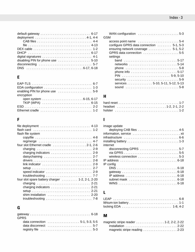
Index - 3
default gateway . . . . . . . . . . . . . . . . . . . . . . . . . . . . 6-17deployment . . . . . . . . . . . . . . . . . . . . . . . . . . . . . 4-1, 4-4
CAB files . . . . . . . . . . . . . . . . . . . . . . . . . . . . . . . 4-4file . . . . . . . . . . . . . . . . . . . . . . . . . . . . . . . . . . . 4-13
DEX cable . . . . . . . . . . . . . . . . . . . . . . . . . . . . . . . . . 1-2DHCP . . . . . . . . . . . . . . . . . . . . . . . . . . . . . . . . . . . 6-17digital signatures . . . . . . . . . . . . . . . . . . . . . . . . . . . . 4-1disabling PIN for phone use . . . . . . . . . . . . . . . . . . 5-10disconnecting . . . . . . . . . . . . . . . . . . . . . . . . . . . . . . 5-7DNS . . . . . . . . . . . . . . . . . . . . . . . . . . . . . . . . 6-17, 6-18
EEAP-TLS . . . . . . . . . . . . . . . . . . . . . . . . . . . . . . . . . . 6-7EDA configuration . . . . . . . . . . . . . . . . . . . . . . . . . . . 1-3enabling PIN for phone use . . . . . . . . . . . . . . . . . . . 5-9encryption
open system . . . . . . . . . . . . . . . . . . . . . . . 6-15, 6-17TKIP (WPA) . . . . . . . . . . . . . . . . . . . . . . . . . . . 6-15
ESD . . . . . . . . . . . . . . . . . . . . . . . . . . . . . . . . . . . . . . 2-2Ethernet cradle . . . . . . . . . . . . . . . . . . . . . . . . . . . . . 1-2
Ffile deployment . . . . . . . . . . . . . . . . . . . . . . . . . . . . 4-13flash card . . . . . . . . . . . . . . . . . . . . . . . . . . . . . . . . . 1-2flash file system
copyfile . . . . . . . . . . . . . . . . . . . . . . . . . . . . . . . . 4-8regmerge . . . . . . . . . . . . . . . . . . . . . . . . . . . . . . 4-7
four slot Ethernet cradle . . . . . . . . . . . . . . . . . . . 2-1, 2-6charging . . . . . . . . . . . . . . . . . . . . . . . . . . . . . . . 2-9charging indicators . . . . . . . . . . . . . . . . . . . . . . . 2-9daisychaining . . . . . . . . . . . . . . . . . . . . . . . . . . . 2-7drivers . . . . . . . . . . . . . . . . . . . . . . . . . . . . . . . . . 2-8link indicator . . . . . . . . . . . . . . . . . . . . . . . . . . . . 2-9setup . . . . . . . . . . . . . . . . . . . . . . . . . . . . . . . . . . 2-7speed indicator . . . . . . . . . . . . . . . . . . . . . . . . . . 2-9troubleshooting . . . . . . . . . . . . . . . . . . . . . . . . . . 7-7
four slot spare battery charger . . . . . . . . . 1-2, 2-1, 2-20charging . . . . . . . . . . . . . . . . . . . . . . . . . . . . . . 2-21charging indicators . . . . . . . . . . . . . . . . . . . . . . 2-21setup . . . . . . . . . . . . . . . . . . . . . . . . . . . . . . . . . 2-21shim installation . . . . . . . . . . . . . . . . . . . . . . . . 2-20troubleshooting . . . . . . . . . . . . . . . . . . . . . . . . . . 7-8
Ggateway . . . . . . . . . . . . . . . . . . . . . . . . . . . . . . . . . . 6-18GPRS
data connection . . . . . . . . . . . . . . . . . . 5-1, 5-3, 5-5data disconnect . . . . . . . . . . . . . . . . . . . . . . . . . 5-7registry file . . . . . . . . . . . . . . . . . . . . . . . . . . . . . 5-3
WAN configuration . . . . . . . . . . . . . . . . . . . . . . . 5-3GSM
access point name . . . . . . . . . . . . . . . . . . . . . . . 5-4configure GPRS data connection . . . . . . . . 5-1, 5-3ensuring network coverage . . . . . . . . . . . . . 5-1, 5-2GPRS data connection . . . . . . . . . . . . . . . . . . . . 5-5settings
band . . . . . . . . . . . . . . . . . . . . . . . . . . . . . . 5-17networks . . . . . . . . . . . . . . . . . . . . . . . . . . . 5-14phone . . . . . . . . . . . . . . . . . . . . . . . . . . . . . . 5-8phone info . . . . . . . . . . . . . . . . . . . . . . . . . . 5-17PIN . . . . . . . . . . . . . . . . . . . . . . . . . . . 5-9, 5-10security . . . . . . . . . . . . . . . . . . . . . . . . . . . . . 5-9services . . . . . . . . . . . . . . 5-10, 5-11, 5-12, 5-13sound . . . . . . . . . . . . . . . . . . . . . . . . . . . . . . 5-8
Hhard reset . . . . . . . . . . . . . . . . . . . . . . . . . . . . . . . . . . 1-7headset . . . . . . . . . . . . . . . . . . . . . . . . . . . . 1-2, 2-1, 2-2holster . . . . . . . . . . . . . . . . . . . . . . . . . . . . . . . . . . . . 1-2
Iimage update
deploying CAB files . . . . . . . . . . . . . . . . . . . . . . . 4-5information, service . . . . . . . . . . . . . . . . . . . . . . . . . . . xiiinfrastructure . . . . . . . . . . . . . . . . . . . . . . . . . . . . . . . 6-6installing battery . . . . . . . . . . . . . . . . . . . . . . . . . . . . . 1-3internet
disconnecting GPRS . . . . . . . . . . . . . . . . . . . . . . 5-7via GPRS . . . . . . . . . . . . . . . . . . . . . . . . . . . . . . . 5-5wireless connection . . . . . . . . . . . . . . . . . . . . . . . 5-3
IP address . . . . . . . . . . . . . . . . . . . . . . . . . . . . . . . . 6-18IP config
DNS . . . . . . . . . . . . . . . . . . . . . . . . . . . . . . . . . . 6-18gateway . . . . . . . . . . . . . . . . . . . . . . . . . . . . . . . 6-18IP address . . . . . . . . . . . . . . . . . . . . . . . . . . . . . 6-18subnet mask . . . . . . . . . . . . . . . . . . . . . . . . . . . 6-18WINS . . . . . . . . . . . . . . . . . . . . . . . . . . . . . . . . . 6-18
LLEAP . . . . . . . . . . . . . . . . . . . . . . . . . . . . . . . . . . . . . 6-8lithium-ion battery . . . . . . . . . . . . . . . . . . . . . . . . . . . . 1-1locking EDA . . . . . . . . . . . . . . . . . . . . . . . . . . . . 1-8, 4-2
Mmagnetic stripe reader . . . . . . . . . . . . . . . . 1-2, 2-2, 2-22
installation . . . . . . . . . . . . . . . . . . . . . . . . . . . . . 2-22magnetic stripe reading . . . . . . . . . . . . . . . . . . . 2-23
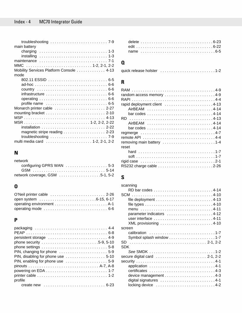
Index - 4 MC70 Integrator Guide
troubleshooting . . . . . . . . . . . . . . . . . . . . . . . . . . 7-9main battery
charging . . . . . . . . . . . . . . . . . . . . . . . . . . . . . . . 1-3installing . . . . . . . . . . . . . . . . . . . . . . . . . . . . . . . 1-3
maintenance . . . . . . . . . . . . . . . . . . . . . . . . . . . . . . . 7-1MMC . . . . . . . . . . . . . . . . . . . . . . . . . . . . . . 1-2, 2-1, 2-2Mobility Services Platform Console . . . . . . . . . . . . . 4-13mode
802.11 ESSID . . . . . . . . . . . . . . . . . . . . . . . . . . . 6-5ad-hoc . . . . . . . . . . . . . . . . . . . . . . . . . . . . . . . . . 6-6country . . . . . . . . . . . . . . . . . . . . . . . . . . . . . . . . 6-6infrastructure . . . . . . . . . . . . . . . . . . . . . . . . . . . . 6-6operating . . . . . . . . . . . . . . . . . . . . . . . . . . . . . . . 6-6profile name . . . . . . . . . . . . . . . . . . . . . . . . . . . . 6-5
Monarch printer cable . . . . . . . . . . . . . . . . . . . . . . . 2-27mounting bracket . . . . . . . . . . . . . . . . . . . . . . . . . . . 2-10MSP . . . . . . . . . . . . . . . . . . . . . . . . . . . . . . . . . . . . . 4-13MSR . . . . . . . . . . . . . . . . . . . . . . . . . . . . . . 1-2, 2-2, 2-22
installation . . . . . . . . . . . . . . . . . . . . . . . . . . . . . 2-22magnetic stripe reading . . . . . . . . . . . . . . . . . . . 2-23troubleshooting . . . . . . . . . . . . . . . . . . . . . . . . . . 7-9
multi media card . . . . . . . . . . . . . . . . . . . . . 1-2, 2-1, 2-2
Nnetwork
configuring GPRS WAN . . . . . . . . . . . . . . . . . . . 5-3GSM . . . . . . . . . . . . . . . . . . . . . . . . . . . . . . . . . 5-14
network coverage, GSM . . . . . . . . . . . . . . . . . . .5-1, 5-2
OO’Neil printer cable . . . . . . . . . . . . . . . . . . . . . . . . . 2-26open system . . . . . . . . . . . . . . . . . . . . . . . . . .6-15, 6-17operating environment . . . . . . . . . . . . . . . . . . . . . . . . A-1operating mode . . . . . . . . . . . . . . . . . . . . . . . . . . . . . 6-6
Ppackaging . . . . . . . . . . . . . . . . . . . . . . . . . . . . . . . . . 4-4PEAP . . . . . . . . . . . . . . . . . . . . . . . . . . . . . . . . . . . . . 6-8persistent storage . . . . . . . . . . . . . . . . . . . . . . . . . . . 4-9phone security . . . . . . . . . . . . . . . . . . . . . . . . . .5-9, 5-10phone settings . . . . . . . . . . . . . . . . . . . . . . . . . . . . . . 5-8PIN, changing for phone . . . . . . . . . . . . . . . . . . . . . . 5-9PIN, disabling for phone use . . . . . . . . . . . . . . . . . . 5-10PIN, enabling for phone use . . . . . . . . . . . . . . . . . . . 5-9pinouts . . . . . . . . . . . . . . . . . . . . . . . . . . . . . . . . A-7, A-8powering on EDA . . . . . . . . . . . . . . . . . . . . . . . . . . . . 1-7printer cable . . . . . . . . . . . . . . . . . . . . . . . . . . . . . . . . 1-2profile
create new . . . . . . . . . . . . . . . . . . . . . . . . . . . . 6-23
delete . . . . . . . . . . . . . . . . . . . . . . . . . . . . . . . . . 6-23edit . . . . . . . . . . . . . . . . . . . . . . . . . . . . . . . . . . . 6-22name . . . . . . . . . . . . . . . . . . . . . . . . . . . . . . . . . . 6-5
Qquick release holster . . . . . . . . . . . . . . . . . . . . . . . . . 1-2
RRAM . . . . . . . . . . . . . . . . . . . . . . . . . . . . . . . . . . . . . . 4-9random access memory . . . . . . . . . . . . . . . . . . . . . . . 4-9RAPI . . . . . . . . . . . . . . . . . . . . . . . . . . . . . . . . . . . . . . 4-4rapid deployment client . . . . . . . . . . . . . . . . . . . . . . 4-13
AirBEAM . . . . . . . . . . . . . . . . . . . . . . . . . . . . . . 4-14bar codes . . . . . . . . . . . . . . . . . . . . . . . . . . . . . . 4-14
RD . . . . . . . . . . . . . . . . . . . . . . . . . . . . . . . . . . . . . . 4-13AirBEAM . . . . . . . . . . . . . . . . . . . . . . . . . . . . . . 4-14bar codes . . . . . . . . . . . . . . . . . . . . . . . . . . . . . . 4-14
regmerge . . . . . . . . . . . . . . . . . . . . . . . . . . . . . . . . . . 4-7remote API . . . . . . . . . . . . . . . . . . . . . . . . . . . . . . . . . 4-4removing main battery . . . . . . . . . . . . . . . . . . . . . . . . 1-4reset
hard . . . . . . . . . . . . . . . . . . . . . . . . . . . . . . . . . . . 1-7soft . . . . . . . . . . . . . . . . . . . . . . . . . . . . . . . . . . . . 1-7
rigid case . . . . . . . . . . . . . . . . . . . . . . . . . . . . . . . . . . 2-1RS232 charge cable . . . . . . . . . . . . . . . . . . . . . . . . . 2-26
Sscanning
RD bar codes . . . . . . . . . . . . . . . . . . . . . . . . . . . 4-14SCM . . . . . . . . . . . . . . . . . . . . . . . . . . . . . . . . . . . . . 4-10
file deployment . . . . . . . . . . . . . . . . . . . . . . . . . . 4-13file types . . . . . . . . . . . . . . . . . . . . . . . . . . . . . . . 4-10menu . . . . . . . . . . . . . . . . . . . . . . . . . . . . . . . . . 4-11parameter indicators . . . . . . . . . . . . . . . . . . . . . 4-12user interface . . . . . . . . . . . . . . . . . . . . . . . . . . . 4-11XML provisioning . . . . . . . . . . . . . . . . . . . . . . . . 4-10
screencalibration . . . . . . . . . . . . . . . . . . . . . . . . . . . . . . 1-7Symbol splash window . . . . . . . . . . . . . . . . . . . . . 1-7
SD . . . . . . . . . . . . . . . . . . . . . . . . . . . . . . . . . . . 2-1, 2-2SDK
See SMDK . . . . . . . . . . . . . . . . . . . . . . . . . . . . . . 1-2secure digital card . . . . . . . . . . . . . . . . . . . . . . . 2-1, 2-2security . . . . . . . . . . . . . . . . . . . . . . . . . . . . . . . . . . . . 4-1
application . . . . . . . . . . . . . . . . . . . . . . . . . . . . . . 4-1certificates . . . . . . . . . . . . . . . . . . . . . . . . . . . . . . 4-3device management . . . . . . . . . . . . . . . . . . . . . . . 4-3digital signatures . . . . . . . . . . . . . . . . . . . . . . . . . 4-1locking device . . . . . . . . . . . . . . . . . . . . . . . . . . . 4-2
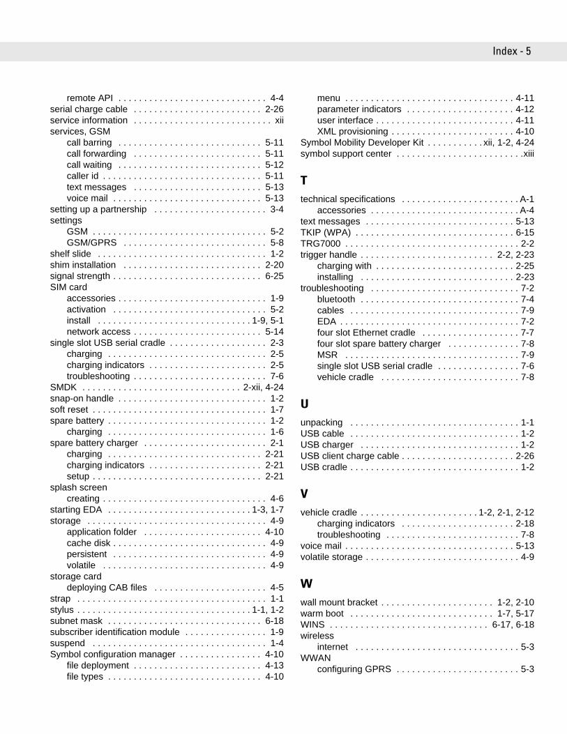
Index - 5
remote API . . . . . . . . . . . . . . . . . . . . . . . . . . . . . 4-4serial charge cable . . . . . . . . . . . . . . . . . . . . . . . . . 2-26service information . . . . . . . . . . . . . . . . . . . . . . . . . . . xiiservices, GSM
call barring . . . . . . . . . . . . . . . . . . . . . . . . . . . . 5-11call forwarding . . . . . . . . . . . . . . . . . . . . . . . . . 5-11call waiting . . . . . . . . . . . . . . . . . . . . . . . . . . . . 5-12caller id . . . . . . . . . . . . . . . . . . . . . . . . . . . . . . . 5-11text messages . . . . . . . . . . . . . . . . . . . . . . . . . 5-13voice mail . . . . . . . . . . . . . . . . . . . . . . . . . . . . . 5-13
setting up a partnership . . . . . . . . . . . . . . . . . . . . . . 3-4settings
GSM . . . . . . . . . . . . . . . . . . . . . . . . . . . . . . . . . . 5-2GSM/GPRS . . . . . . . . . . . . . . . . . . . . . . . . . . . . 5-8
shelf slide . . . . . . . . . . . . . . . . . . . . . . . . . . . . . . . . . 1-2shim installation . . . . . . . . . . . . . . . . . . . . . . . . . . . 2-20signal strength . . . . . . . . . . . . . . . . . . . . . . . . . . . . . 6-25SIM card
accessories . . . . . . . . . . . . . . . . . . . . . . . . . . . . . 1-9activation . . . . . . . . . . . . . . . . . . . . . . . . . . . . . . 5-2install . . . . . . . . . . . . . . . . . . . . . . . . . . . . . . 1-9, 5-1network access . . . . . . . . . . . . . . . . . . . . . . . . . 5-14
single slot USB serial cradle . . . . . . . . . . . . . . . . . . . 2-3charging . . . . . . . . . . . . . . . . . . . . . . . . . . . . . . . 2-5charging indicators . . . . . . . . . . . . . . . . . . . . . . . 2-5troubleshooting . . . . . . . . . . . . . . . . . . . . . . . . . . 7-6
SMDK . . . . . . . . . . . . . . . . . . . . . . . . . . . . . . . 2-xii, 4-24snap-on handle . . . . . . . . . . . . . . . . . . . . . . . . . . . . . 1-2soft reset . . . . . . . . . . . . . . . . . . . . . . . . . . . . . . . . . . 1-7spare battery . . . . . . . . . . . . . . . . . . . . . . . . . . . . . . . 1-2
charging . . . . . . . . . . . . . . . . . . . . . . . . . . . . . . . 1-6spare battery charger . . . . . . . . . . . . . . . . . . . . . . . . 2-1
charging . . . . . . . . . . . . . . . . . . . . . . . . . . . . . . 2-21charging indicators . . . . . . . . . . . . . . . . . . . . . . 2-21setup . . . . . . . . . . . . . . . . . . . . . . . . . . . . . . . . . 2-21
splash screencreating . . . . . . . . . . . . . . . . . . . . . . . . . . . . . . . . 4-6
starting EDA . . . . . . . . . . . . . . . . . . . . . . . . . . . . 1-3, 1-7storage . . . . . . . . . . . . . . . . . . . . . . . . . . . . . . . . . . . 4-9
application folder . . . . . . . . . . . . . . . . . . . . . . . 4-10cache disk . . . . . . . . . . . . . . . . . . . . . . . . . . . . . . 4-9persistent . . . . . . . . . . . . . . . . . . . . . . . . . . . . . . 4-9volatile . . . . . . . . . . . . . . . . . . . . . . . . . . . . . . . . 4-9
storage carddeploying CAB files . . . . . . . . . . . . . . . . . . . . . . 4-5
strap . . . . . . . . . . . . . . . . . . . . . . . . . . . . . . . . . . . . . 1-1stylus . . . . . . . . . . . . . . . . . . . . . . . . . . . . . . . . . . 1-1, 1-2subnet mask . . . . . . . . . . . . . . . . . . . . . . . . . . . . . . 6-18subscriber identification module . . . . . . . . . . . . . . . . 1-9suspend . . . . . . . . . . . . . . . . . . . . . . . . . . . . . . . . . . 1-4Symbol configuration manager . . . . . . . . . . . . . . . . 4-10
file deployment . . . . . . . . . . . . . . . . . . . . . . . . . 4-13file types . . . . . . . . . . . . . . . . . . . . . . . . . . . . . . 4-10
menu . . . . . . . . . . . . . . . . . . . . . . . . . . . . . . . . . 4-11parameter indicators . . . . . . . . . . . . . . . . . . . . . 4-12user interface . . . . . . . . . . . . . . . . . . . . . . . . . . . 4-11XML provisioning . . . . . . . . . . . . . . . . . . . . . . . . 4-10
Symbol Mobility Developer Kit . . . . . . . . . . . xii, 1-2, 4-24symbol support center . . . . . . . . . . . . . . . . . . . . . . . . .xiii
Ttechnical specifications . . . . . . . . . . . . . . . . . . . . . . . A-1
accessories . . . . . . . . . . . . . . . . . . . . . . . . . . . . . A-4text messages . . . . . . . . . . . . . . . . . . . . . . . . . . . . . 5-13TKIP (WPA) . . . . . . . . . . . . . . . . . . . . . . . . . . . . . . . 6-15TRG7000 . . . . . . . . . . . . . . . . . . . . . . . . . . . . . . . . . . 2-2trigger handle . . . . . . . . . . . . . . . . . . . . . . . . . . 2-2, 2-23
charging with . . . . . . . . . . . . . . . . . . . . . . . . . . . 2-25installing . . . . . . . . . . . . . . . . . . . . . . . . . . . . . . 2-23
troubleshooting . . . . . . . . . . . . . . . . . . . . . . . . . . . . . 7-2bluetooth . . . . . . . . . . . . . . . . . . . . . . . . . . . . . . . 7-4cables . . . . . . . . . . . . . . . . . . . . . . . . . . . . . . . . . 7-9EDA . . . . . . . . . . . . . . . . . . . . . . . . . . . . . . . . . . . 7-2four slot Ethernet cradle . . . . . . . . . . . . . . . . . . . 7-7four slot spare battery charger . . . . . . . . . . . . . . 7-8MSR . . . . . . . . . . . . . . . . . . . . . . . . . . . . . . . . . . 7-9single slot USB serial cradle . . . . . . . . . . . . . . . . 7-6vehicle cradle . . . . . . . . . . . . . . . . . . . . . . . . . . . 7-8
Uunpacking . . . . . . . . . . . . . . . . . . . . . . . . . . . . . . . . . 1-1USB cable . . . . . . . . . . . . . . . . . . . . . . . . . . . . . . . . . 1-2USB charger . . . . . . . . . . . . . . . . . . . . . . . . . . . . . . . 1-2USB client charge cable . . . . . . . . . . . . . . . . . . . . . . 2-26USB cradle . . . . . . . . . . . . . . . . . . . . . . . . . . . . . . . . . 1-2
Vvehicle cradle . . . . . . . . . . . . . . . . . . . . . . . 1-2, 2-1, 2-12
charging indicators . . . . . . . . . . . . . . . . . . . . . . 2-18troubleshooting . . . . . . . . . . . . . . . . . . . . . . . . . . 7-8
voice mail . . . . . . . . . . . . . . . . . . . . . . . . . . . . . . . . . 5-13volatile storage . . . . . . . . . . . . . . . . . . . . . . . . . . . . . . 4-9
Wwall mount bracket . . . . . . . . . . . . . . . . . . . . . . 1-2, 2-10warm boot . . . . . . . . . . . . . . . . . . . . . . . . . . . . 1-7, 5-17WINS . . . . . . . . . . . . . . . . . . . . . . . . . . . . . . . 6-17, 6-18wireless
internet . . . . . . . . . . . . . . . . . . . . . . . . . . . . . . . . 5-3WWAN
configuring GPRS . . . . . . . . . . . . . . . . . . . . . . . . 5-3
Index - 6 MC70 Integrator Guide
XXML provisioning . . . . . . . . . . . . . . . . . . . . . . . . .4-6, 4-7
certificates . . . . . . . . . . . . . . . . . . . . . . . . . . . . . . 4-3SCM . . . . . . . . . . . . . . . . . . . . . . . . . . . . . . . . . 4-10
ZZebra printer cable . . . . . . . . . . . . . . . . . . . . . . . . . 2-26

Tell Us What You Think...We’d like to know what you think about this Manual. Please take a moment to fill out this questionnaire and fax this form to: (631) 738-3318, or mail to:
Symbol Technologies, Inc.One Symbol Plaza M/S B-4Holtsville, NY 11742-1300 Attention: Technical Publications Manager
IMPORTANT: If you need product support, please call the appropriate customer support number provided. Unfortunately, we cannot provide customer support at the fax number above.
Manual Title:___________________________________________(please include revision level)
How familiar were you with this product before using this manual?
Did this manual meet your needs? If not, please explain.________________________________________________________________________________________________________________________________________________________________________________________________________________________________________________________________________________________________________________________________________________________
What topics need to be added to the index, if applicable? ________________________________________________________________________________________________________________________________________________________________________________________________________________________________________________________________________________________________________________________________________________________
What topics do you feel need to be better discussed? Please be specific.________________________________________________________________________________________________________________________________________________________________________________________________________________________________________________________________________________________________________________________________________________________
What can we do to further improve our manuals?________________________________________________________________________________________________________________________________________________________________________________________________________________________________________________________________________________________________________________________________________________________
Very familiar Slightly familiar Not at all familiar
Thank you for your input—We value your comments.


Symbol Technologies, Inc.One Symbol PlazaHoltsville, New York 11742-1300http://www.symbol.com
72E-71768-01Revision A - January 2006
Related Documents