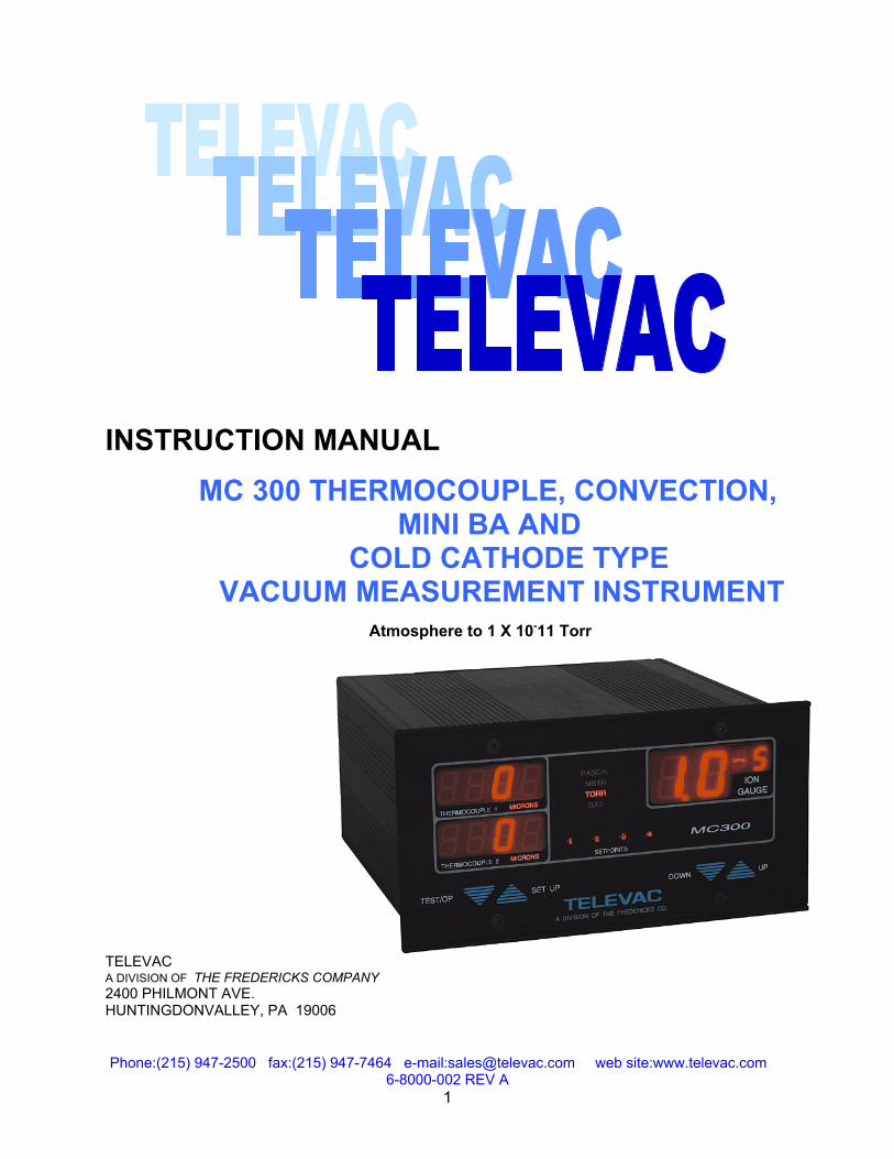
Phone:(215) 947-2500 fax:(215) 947-7464 e-mail:[email protected] web site:www.televac.com 6-8000-002 REV A 1 INSTRUCTION MANUAL MC 300 THERMOCOUPLE, CONVECTION, MINI BA AND COLD CATHODE TYPE VACUUM MEASUREMENT INSTRUMENT Atmosphere to 1 X 10 - 11 Torr TELEVAC A DIVISION OF THE FREDERICKS COMPANY 2400 PHILMONT AVE. HUNTINGDONVALLEY, PA 19006

Welcome message from author
This document is posted to help you gain knowledge. Please leave a comment to let me know what you think about it! Share it to your friends and learn new things together.
Transcript
Phone:(215) 947-2500 fax:(215) 947-7464 e-mail:[email protected] web site:www.televac.com 6-8000-002 REV A
1
INSTRUCTION MANUAL
MC 300 THERMOCOUPLE, CONVECTION, MINI BA AND COLD CATHODE TYPE
VACUUM MEASUREMENT INSTRUMENT Atmosphere to 1 X 10-11 Torr TELEVAC A DIVISION OF THE FREDERICKS COMPANY 2400 PHILMONT AVE. HUNTINGDONVALLEY, PA 19006
Phone:(215) 947-2500 fax:(215) 947-7464 e-mail:[email protected] web site:www.televac.com 6-8000-002 REV A
2
THERMOCOUPLE 2
THERMOCOUPLE 1
TEST/OP
4321
A DIVISION OF THE FREDERICKS CO.
MICRONS
SET UP
SETPOINTS
DOWN UP
MICRONSTORRGAS
MBARPASCAL
GAUGEION
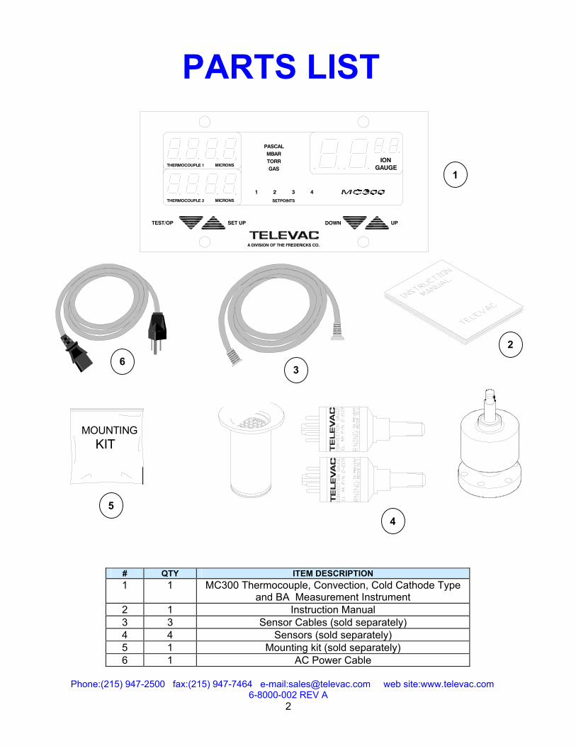
# QTY ITEM DESCRIPTION 1 1 MC300 Thermocouple, Convection, Cold Cathode Type
and BA Measurement Instrument 2 1 Instruction Manual 3 3 Sensor Cables (sold separately) 4 4 Sensors (sold separately) 5 1 Mounting kit (sold separately) 6 1 AC Power Cable
2
1
PARTS LIST
3
MOUNTING KIT
5 4
6
Phone:(215) 947-2500 fax:(215) 947-7464 e-mail:[email protected] web site:www.televac.com 6-8000-002 REV A
3
TABLE OF CONTENTS SECTION TITLE PAGE(S)
01. DESCRIPTION …………………………………………………………………………..2 - 4 02. SAFETY INSTRUCTIONS….. ..……………………………………………………….5 & 6 03. PRINCIPLES OF OPERATION ……………………………………………………….6 & 7 04. INSTALLATION & OPERATION………………………………………………………8 - 12 05. RECORDER OUTPUTS ……………………………………………………………………7 06. MAINTENANCE …..………………………………..…………………………………15 & 16 07. CALIBRATION……….. ……………………………………………………………………17 08. CALIBRATION VERIFICATION………….………………………………………….…….17 09. TROUBLESHOOTING………..…………………………………………………………….18 10. SPECIFICATIONS………………..…………………………………………………………18 11. DIMENSIONS…….. ………………………………………………………………………...19 12. UNPACKING AND INSPECTION……………..…………………………………………..19 13. WARRANTY INFORMATION ……………………………………………………….…….20 14. ORDERING INFORMATION……………………………………………………………….21
PLEASE READ THIS MANUAL THOROUGHLY BEFORE USING THIS INSTRUMENT. REPORT ANY PROBLEMS IMMEDIATELY.
Phone:(215) 947-2500 fax:(215) 947-7464 e-mail:[email protected] web site:www.televac.com 6-8000-002 REV A
4
CHAPTER 1 TELEVAC Description The Televac Series MC300 vacuum-measuring instrument is a combination sensor, which incorporates various range options, as shown in the table below:
Range of Options Model Range Sensors MC2A7B 0 - 20,000 millitorr, 2AThermocouple 10-3 To 10-7 Torr 7B2 Cold Cathode MC4A7B 0 – Atmosphere, 4A Convection 10-3 To 10-7 Torr 7B2 Cold Cathode MC2A7E/F/FC/FCS 0 - 20,000 millitorr, 2A Thermocouple 10-2 To 2 X 10-11 Torr * 7E/F/FC/FCS Cold
Cathode MC4A7E/F/FC/FCS 0 – Atmosphere, 4A Convection 10-2 To 2 X 10-11 Torr * 7E/F/FC/FCS Cold
Cathode MC2ABA 0 - 20,000 microns, 2A Thermocouple 10-2 To 2 X 10⁻¹⁰ Torr Mini BA MC4ABA 0 – Atmosphere, 4A Convection 10-2 To 2 X 10⁻¹⁰ Torr Mini BA
* With the 7E sensor, the range is limited to 10-8 Torr
The 2A thermocouple sensor tube will monitor pressures between 1 millitorr (1 micron) and 20,000 microns
The 4A convection sensor tube will monitor pressures between 1 millitorr (1 micron) and 999 Torr. (1 atmosphere = 760 Torr @ sea level
The 7B2 cold cathode sensor tube will monitor pressures between 1 millitorr (1 micron) and 10-7 Torr.
The 7E/F/FC/FCS cold cathode sensor will monitor pressures between 10 millitorr (10 microns) and 10-8, 2 X 10-11, AND 2 X 10-11 Torr.
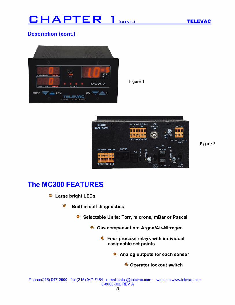
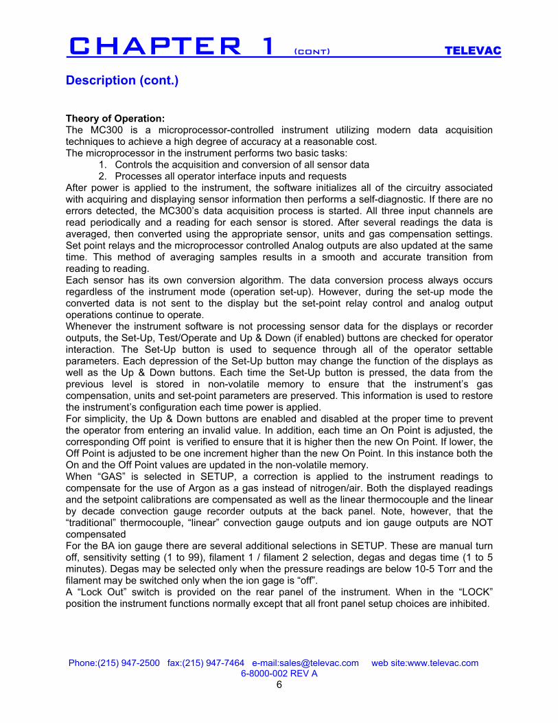
The Mini BA sensor will monitor pressures between 10 milliitorr (10 microns) and 2 X 10⁻¹⁰ Torr. The vacuum measuring system consists of various sensor tubes, which sense the vacuum, an electronics unit and interconnecting signal/power cables. The customer must supply power at 115VAC 50-60 Hz. (220 Volt operation is a factory selectable option). The measured vacuum is displayed on the front panel LED displays, see figure 1. The power cables, sensor tubes, relay outputs and output voltages of 0 to 10 VDC connections are on the back panel, see figure 2.
Phone:(215) 947-2500 fax:(215) 947-7464 e-mail:[email protected] web site:www.televac.com 6-8000-002 REV A
5
Description (cont.) The MC300 FEATURES
Large bright LEDs
Built-in self-diagnostics
Selectable Units: Torr, microns, mBar or Pascal
Gas compensation: Argon/Air-Nitrogen
Four process relays with individual assignable set points
Analog outputs for each sensor
Operator lockout switch
Figure 1
Figure 2
CHAPTER 1(cont.) TELEVAC
Phone:(215) 947-2500 fax:(215) 947-7464 e-mail:[email protected] web site:www.televac.com 6-8000-002 REV A
6
CHAPTER 1 (cont) TELEVAC Description (cont.) Theory of Operation: The MC300 is a microprocessor-controlled instrument utilizing modern data acquisition techniques to achieve a high degree of accuracy at a reasonable cost. The microprocessor in the instrument performs two basic tasks:
1. Controls the acquisition and conversion of all sensor data 2. Processes all operator interface inputs and requests
After power is applied to the instrument, the software initializes all of the circuitry associated with acquiring and displaying sensor information then performs a self-diagnostic. If there are no errors detected, the MC300’s data acquisition process is started. All three input channels are read periodically and a reading for each sensor is stored. After several readings the data is averaged, then converted using the appropriate sensor, units and gas compensation settings. Set point relays and the microprocessor controlled Analog outputs are also updated at the same time. This method of averaging samples results in a smooth and accurate transition from reading to reading. Each sensor has its own conversion algorithm. The data conversion process always occurs regardless of the instrument mode (operation set-up). However, during the set-up mode the converted data is not sent to the display but the set-point relay control and analog output operations continue to operate. Whenever the instrument software is not processing sensor data for the displays or recorder outputs, the Set-Up, Test/Operate and Up & Down (if enabled) buttons are checked for operator interaction. The Set-Up button is used to sequence through all of the operator settable parameters. Each depression of the Set-Up button may change the function of the displays as well as the Up & Down buttons. Each time the Set-Up button is pressed, the data from the previous level is stored in non-volatile memory to ensure that the instrument’s gas compensation, units and set-point parameters are preserved. This information is used to restore the instrument’s configuration each time power is applied. For simplicity, the Up & Down buttons are enabled and disabled at the proper time to prevent the operator from entering an invalid value. In addition, each time an On Point is adjusted, the corresponding Off point is verified to ensure that it is higher then the new On Point. If lower, the Off Point is adjusted to be one increment higher than the new On Point. In this instance both the On and the Off Point values are updated in the non-volatile memory. When “GAS” is selected in SETUP, a correction is applied to the instrument readings to compensate for the use of Argon as a gas instead of nitrogen/air. Both the displayed readings and the setpoint calibrations are compensated as well as the linear thermocouple and the linear by decade convection gauge recorder outputs at the back panel. Note, however, that the “traditional” thermocouple, “linear” convection gauge outputs and ion gauge outputs are NOT compensated For the BA ion gauge there are several additional selections in SETUP. These are manual turn off, sensitivity setting (1 to 99), filament 1 / filament 2 selection, degas and degas time (1 to 5 minutes). Degas may be selected only when the pressure readings are below 10-5 Torr and the filament may be switched only when the ion gage is “off”. A “Lock Out” switch is provided on the rear panel of the instrument. When in the “LOCK” position the instrument functions normally except that all front panel setup choices are inhibited.
Phone:(215) 947-2500 fax:(215) 947-7464 e-mail:[email protected] web site:www.televac.com 6-8000-002 REV A
7
CHAPTER 2 TELEVAC Safety Instructions START BY READING THESE IMPORTANT SAFETY INSTRUCTIONS AND NOTES collected here for your convenience and repeated with additional information at appropriate points in these instructions In these instructions the word “product” refers to the MC300 and all of its approved parts and accessories. NOTE: These instructions do not and cannot provide for every contingency that may arise in connection with the installation, operation, or maintenance of this product. Should you require further assistance, please contact Televac at the address on the title page of this manual. This product has been designed and tested to offer reasonably safe service provided in it’s installed, operated and serviced in strict accordance with these safety instructions. These safety precautions must be observed during all phases of operation, installation, and service of this product. Failure to comply with these precautions or with specific warnings elsewhere in this manual violates safety standards of design, manufacture, and intended use of the instrument. Televac disclaims all liability for the customer’s failure to comply with these requirements.
√ READ Instructions – Read all safety and operating instructions before operating the product. √ RETAIN instructions – Retain the Safety and Operating Instructions for future reference. √ HEED warnings – Adhere to all warnings on the product and in the operating instructions. √ FOLLOW instructions – Follow all operating and maintenance instructions. √ ACCESORIES – Do not use accessories not recommended in this manual as they may require a technician to restore the product to its normal operation.
These safety alert symbols in this manual or on the Product rear panel mean cautions - personal safety, property damage or danger from electrical shock. Read these instructions carefully.
Failure to comply with these instructions may result in serious personal injury, including death, or property damage.
The service and repair information in this manual is for the use of Qualified Service Personnel. To avoid shock, do not perform any procedures in this manual or perform any Servicing on this product unless you are qualified to do so.
To reduce risk of fire or electric shock, do not expose this product to rain or moisture.
Phone:(215) 947-2500 fax:(215) 947-7464 e-mail:[email protected] web site:www.televac.com 6-8000-002 REV A
8
CHAPTER 2 (cont.) TELEVAC
CHAPTER 3
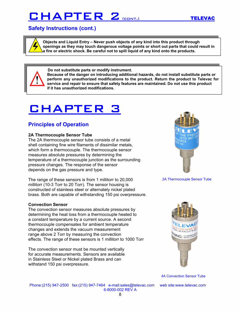
Safety Instructions (cont.) ` Principles of Operation 2A Thermocouple Sensor Tube The 2A thermocouple sensor tube consists of a metal shell containing fine wire filaments of dissimilar metals, which form a thermocouple. The thermocouple sensor measures absolute pressures by determining the temperature of a thermocouple junction as the surrounding pressure changes. The response of the sensor depends on the gas pressure and type. The range of these sensors is from 1 millitorr to 20,000 millitorr (10-3 Torr to 20 Torr). The sensor housing is constructed of stainless steel or alternately nickel plated brass. Both are capable of withstanding 150 psi overpressure. Convection Sensor The convection sensor measures absolute pressures by determining the heat loss from a thermocouple heated to a constant temperature by a current source. A second thermocouple compensates for ambient temperature changes and extends the vacuum measurement range above 2 Torr by measuring the convection effects. The range of these sensors is 1 millitorr to 1000 Torr The convection sensor must be mounted vertically for accurate measurements. Sensors are available in Stainless Steel or Nickel plated Brass and can withstand 150 psi overpressure.
Objects and Liquid Entry – Never push objects of any kind into this product through openings as they may touch dangerous voltage points or short out parts that could result in a fire or electric shock. Be careful not to spill liquid of any kind onto the products.
Do not substitute parts or modify instrument. Because of the danger on introducing additional hazards, do not install substitute parts or perform any unauthorized modifications to the product. Return the product to Televac for service and repair to ensure that safety features are maintained. Do not use this product if it has unauthorized modifications.
2A Thermocouple Sensor Tube
4A Convection Sensor Tube
Phone:(215) 947-2500 fax:(215) 947-7464 e-mail:[email protected] web site:www.televac.com 6-8000-002 REV A
9
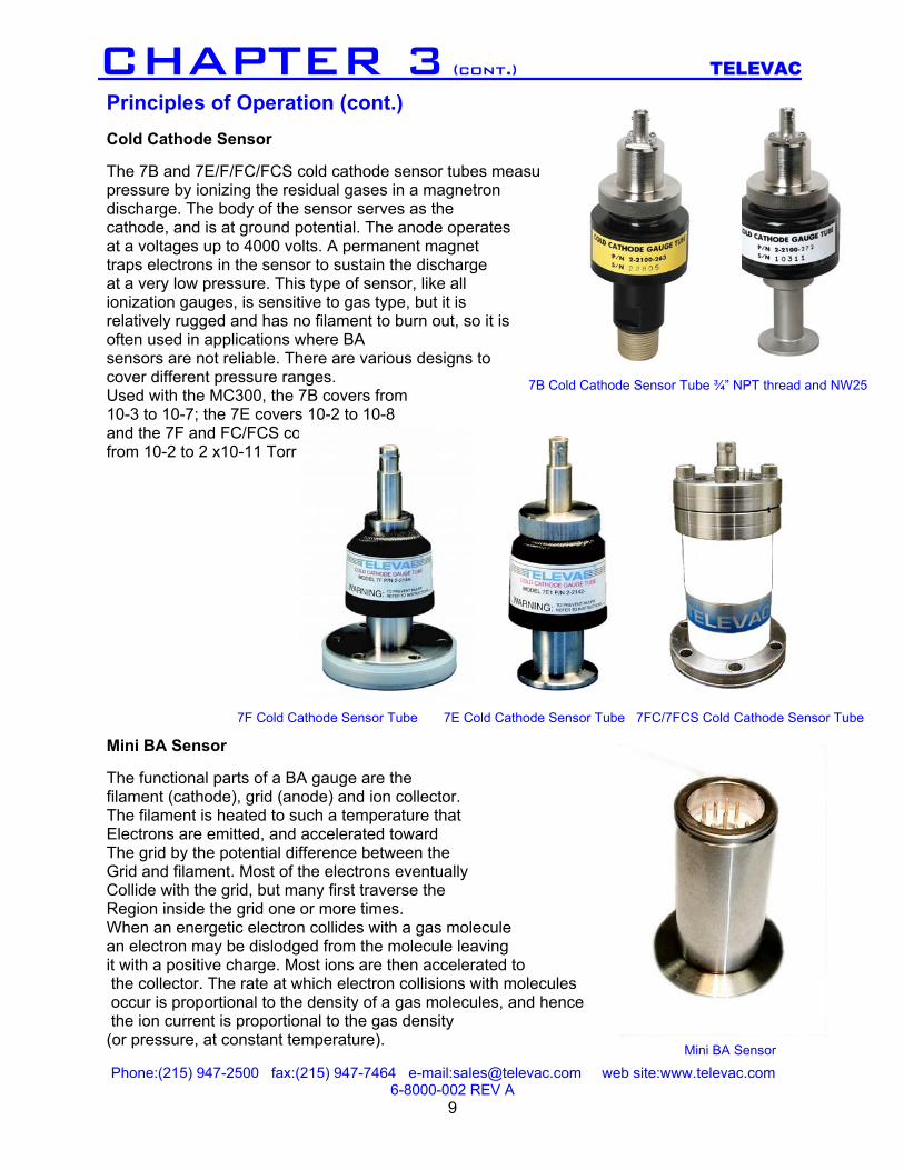
CHAPTER 3 (cont.) TELEVAC Principles of Operation (cont.) Cold Cathode Sensor The 7B and 7E/F/FC/FCS cold cathode sensor tubes measure pressure by ionizing the residual gases in a magnetron discharge. The body of the sensor serves as the cathode, and is at ground potential. The anode operates at a voltages up to 4000 volts. A permanent magnet traps electrons in the sensor to sustain the discharge at a very low pressure. This type of sensor, like all ionization gauges, is sensitive to gas type, but it is relatively rugged and has no filament to burn out, so it is often used in applications where BA sensors are not reliable. There are various designs to cover different pressure ranges. Used with the MC300, the 7B covers from 10-3 to 10-7; the 7E covers 10-2 to 10-8 and the 7F and FC/FCS covers from 10-2 to 2 x10-11 Torr Mini BA Sensor The functional parts of a BA gauge are the filament (cathode), grid (anode) and ion collector. The filament is heated to such a temperature that Electrons are emitted, and accelerated toward The grid by the potential difference between the Grid and filament. Most of the electrons eventually Collide with the grid, but many first traverse the Region inside the grid one or more times. When an energetic electron collides with a gas molecule an electron may be dislodged from the molecule leaving it with a positive charge. Most ions are then accelerated to the collector. The rate at which electron collisions with molecules occur is proportional to the density of a gas molecules, and hence the ion current is proportional to the gas density (or pressure, at constant temperature).
7B Cold Cathode Sensor Tube ¾” NPT thread and NW25
7F Cold Cathode Sensor Tube 7E Cold Cathode Sensor Tube 7FC/7FCS Cold Cathode Sensor Tube
Mini BA Sensor
Phone:(215) 947-2500 fax:(215) 947-7464 e-mail:[email protected] web site:www.televac.com 6-8000-002 REV A
10
CHAPTER 4 TELEVAC Installation and Operation Instrument Installation 1.0 The MC300 is pre configured for immediate installation and use. The unit should be first
mounted in the desired location and properly secured. In choosing a location, the display should be clearly visible by an operator and positioned in such a way that the operator can easily make adjustments to the instrument. All wiring should be neatly dressed and bundled with special care not to have any wiring adjacent to AC power distribution. After proper installation of sensors and wiring, the unit can be connected to an AC power source and put into operation. IT IS RECOMMENDED THAT POWER IS NOT APPLIED TO THE INSTRUMENT DURING THE INSTALLATION OF ANY WIRING AND SENSORS.
Sensor Installation It is desirable that the thermocouple and cold cathode sensor tubes be mounted on the vacuum system in a VERTICAL POSITION open end extending downward. The 4A convection sensor should be installed in the VERTICAL POSITION. The electronic unit is factory calibrated at time of order. To ensure proper operating conditions it is necessary to use factory-manufactured cables. Contamination of thermocouples sensor can be caused by the process occurring
in the vacuum vessel, or by pump fluid backstreaming and is a critical factor affecting the measurement of high vacuum. Depending upon the degree of contamination and the accuracy required, it is recommended that sensor be periodically replaced and that filters (with line of sight baffles [P/N 2-2100-50]) be used to protect thermocouple sensors.
The thermocouple and convection sensor tubes incorporate a 1/8” National Pipe Thread (1/8” NPT) fitting for connection to the vacuum system and other mounting configurations are available. The instrument may be turned on at any time, since atmospheric pressure will not harm the thermocouple sensor tube elements or cause overdrive on the metering circuit. A brief 15-minute warm up is required before vacuum measurements can be made within stated tolerances.

Phone:(215) 947-2500 fax:(215) 947-7464 e-mail:[email protected] web site:www.televac.com 6-8000-002 REV A
11
CHAPTER 4 (cont.) TELEVAC Installation and Operation (cont.) Wiring the instrument Sensor wiring The MC300 requires sensors & cables (sold separately) for each channel. Certain levels of calibration require a specific cable and sensor be used with channel 1 or 2. In this case the cable and sensor are marked for use as a set and must be used as such. Otherwise the cables can be used with either rough vacuum channel. To ensure measurement integrity and protection from ambient electrical noise, ground lugs are provided on each sensor cable shield. These lugs should be connected to the ground screws provided on the rear panel.
Input #1 controls the Ion gauge on/off function. It is imperative that this sensor be located in the same chamber as the high vacuum sensor (ionization tube). Input #2 is an auxiliary input that can be used to monitor an intermediate vacuum level such as a mechanical rough pump. It CANNOT be used to control the high vacuum sensor.
Analog Output Wiring Provisions are made to connect the instrument to a chart recorder or programmable logic controller. Two different format signals are provided and are described in Section 5 Analog Outputs. In all cases follow the external device manufacturer’s instructions for wiring and using these signals. Linear (LIN) output is computer generated so that the voltage signal is plotted as a straight line as a function of pressure. Traditional (TRDL) signal is one that represents the non-linear signal that is representative of the actual raw sensor data. The 4A Convection version has Linear/Decade and Linear outputs. By means of a factory settable internal jumper a full range Traditional signal is available in lieu of the Linear/Decade recorder output. Please refer to Section 5 Analog Output (4A) for a summary of the signals available Relay Contact Wiring (Setpoint Relays) There are four setpoint relays available for use to control ON/OFF or Open/close (binary state) devices. The relays are assignable to any one of the vacuum signal input channels through front panel software control. There are three connections for each relay. They are NORMALLY CLOSED (NC), COMMON (C) and NORMALLY OPEN (O). The operation mode of each is described as follows.
Input #3 is a HIGH VOLTAGE coaxial connection. The main AC power to the MC300 MUST BE DISCONNECTED BEFORE THIS CABLE IS ATTTACHED OR REMOVED. EXTEME CAUTION IS ADVISED when making connections to a process vacuum
system, as high voltages may be present in the chamber. If a triaxaxial cable is used, with the 7F sensor, the outside shield must be grounded under the screw near the coaxial connector and the internal coax/triax jumper placed in the triax position. For access to the coax/triax jumper, remove all cables and connectors from the rear panel. Remove the three metal-finish grounding screws and the four black screws securing the rear panel. Remove the rear panel. Remove the cold cathode circuit board. Locate J6 and position the coax/triax jumper as required.
Phone:(215) 947-2500 fax:(215) 947-7464 e-mail:[email protected] web site:www.televac.com 6-8000-002 REV A
12
CHAPTER 4 (cont.) TELEVAC Installation and Operation (cont.) NORMALLY CLOSED: In this state there is an electrical continuity path between terminals C and NC. This continuity path is broken when the software set point values dictates an ON state for the specific measurement channel. Continuity is returned when the OFF state is dictated by software control. In the power off mode of the MC300 (due to failure of the main power source or turning off the instrument), the relay will revert to this state. NORMALLY OPEN: In this state there is no electrical continuity path between terminals C and NO. This Path is established ONLY when the Instrument control software satisfies conditions for the ON state. It will break continuity under the instrument control parameters for the OFF condition or the power off mode of the MC300 (due to failure of the main power source or turning off the instrument). CAUTION: In utilizing the process relays it is important not to exceed the relay’s power handling capacity described in Section 10 Specifications and to fully understand the behavior of the control relay state conditions. Failure to do so will result in premature relay or equipment failure. Operating the Instrument This section describes the operation of a properly installed MC300 Instrument Prior to using the instrument on a vacuum chamber, the unit can be set up in a test mode using simulators to represent the vacuum gauges. This is done to gain familiarity with the unit and to preset relay set points. The following describes operation of the instrument with simulators or vacuum applied to the sensors.
Power On: The instrument is turned on and off by means of a rear mounted power switch. The unit will first display the Software version number and instrument type in a four-digit code. The first two digits refer to the software version and the second two digits refer to the Instrument Sensor type summarized below. The instrument will then perform a self-diagnosis after which it will begin displaying vacuum measurements. If the unit doesn’t pass the self-test, an error code will appear. Pressing the “TEST OP ” button can clear the code, but proper operation of the instrument may be curtailed. It is recommended not to use the instrument if the self diagnosis fails. Contact the factory for instructions. Allow a minimum of 15 minutes from an instrument “cold start” for the sensor readings to stabilize.
Phone:(215) 947-2500 fax:(215) 947-7464 e-mail:[email protected] web site:www.televac.com 6-8000-002 REV A
13
CHAPTER 4 (cont.) TELEVAC Installation and Operation (cont.)
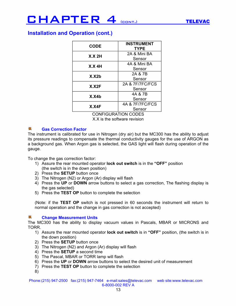
CODE INSTRUMENT TYPE
X.X 2H 2A & Mini BA Sensor
X.X 4H 4A & Mini BA Sensor
X.X2b 2A & 7B Sensor
X.X2F 2A & 7F/7FC/FCS Sensor
X.X4b 4A & 7B Sensor
X.X4F 4A & 7F/7FC/FCS Sensor
CONFIGURATION CODES X.X is the software revision
Gas Correction Factor The instrument is calibrated for use in Nitrogen (dry air) but the MC300 has the ability to adjust its pressure readings to compensate the thermal conductivity gauges for the use of ARGON as a background gas. When Argon gas is selected, the GAS light will flash during operation of the gauge. To change the gas correction factor:
1) Assure the rear mounted operator lock out switch is in the “OFF” position (the switch is in the down position)
2) Press the SETUP button once 3) The Nitrogen (N2) or Argon (Ar) display will flash 4) Press the UP or DOWN arrow buttons to select a gas correction, The flashing display is
the gas selected) 5) Press the TEST OP button to complete the selection (Note: if the TEST OP switch is not pressed in 60 seconds the instrument will return to normal operation and the change in gas correction is not accepted)
Change Measurement Units
The MC300 has the ability to display vacuum values in Pascals, MBAR or MICRONS and TORR.
1) Assure the rear mounted operator lock out switch is in “OFF” position, (the switch is in the down position)
2) Press the SETUP button once 3) The Nitrogen (N2) and Argon (Ar) display will flash 4) Press the SETUP a second time 5) The Pascal, MBAR or TORR lamp will flash 6) Press the UP or DOWN arrow buttons to select the desired unit of measurement 7) Press the TEST OP button to complete the selection 8)
Phone:(215) 947-2500 fax:(215) 947-7464 e-mail:[email protected] web site:www.televac.com 6-8000-002 REV A
14
CHAPTER 4 (cont.) TELEVAC
Installation and Operation (cont.) (Note: if the TEST OP switch is not pressed in 60 seconds the instrument will return to normal operation and the change in gas correction is not accepted)
Assign Setpoint Relays and Values
The instrument has four relays that are assignable to any of the vacuum measurement channels. Thermocouple (or Convection) Channel 1 is Channel 1 (CH1), thermocouple (or Convection) Channel 2 is Channel 2 (CH2) and the Ion gauge is Channel 3 (CH3). Setpoint SP 1 is relay #1, setpoint SP 2 is relay #2 etc.
1) Assure the rear mounted operator lock out switch is in the “OFF” position, (the switch is in the down position)
2) Press the SETUP button once 3) The Nitrogen (N2) or Argon (Ar) display will flash 4) Press the SETUP a second time
The measurement units (PASCAL, MBAR or TORR) lamp will flash 5) Press the SETUP a third time 6) The set point SP 1 will appear in the left display, the channel number CH1, 2 or 3 will
appear in the right display 7) Use the UP or DOWN arrows to select the channel number 1,2 or 3 8) Press the SETUP button again. “ON” will appear in the right display, the “ON” value will
appear in the lower left display 9) Press the UP/DOWN button to adjust the “ON” value. Press and hold the UP/DOWN
button to rapidly advance the “ON” value. 10) Press the SET UP button again. “OFF” will appear in the right display the relay “OFF”
value will appear in the lower left display 11) Press the UP/DOWN buttons to adjust the “OFF” value. Press and hold the UP/DOWN
button to rapidly advance the “OFF” value. 12) Press the SET UP button again and the next relay, SP 2 will appear. The sequence
listed in steps 6 and 11 are repeated until all four relays have been assigned. The MC300 will return to its normal operating mode after the fourth relay has been set up or 60 seconds have elapsed since the last button press. Changes are stored after the complete set up of an individual relay channel. These set up parameters are stored in Non volatile memory and are not lost during Power outages. Note: Set point changes are also accepted by the MC300 by pressing the “TEST OP” button at any point in the set up. The Instrument will not accept “OFF” values that are lower than the “ON” value. “ON” values entered that are greater than the ”OFF” values will automatically change the “OFF” value one unit higher than “ON”.
IONIZATION GAUGE – additional setups ON/OFF The first setup position allows the BA sensor to be turned off even though the channel #1 pressure is below 10 microns. In this case, “OFF” will be displayed whether the pressure is above or below 10 microns. In normal “ON” operation the ion gage displays “RDY” until the channel #1 pressure drops below 10 microns, after which it displays the ion gauge reading.
Phone:(215) 947-2500 fax:(215) 947-7464 e-mail:[email protected] web site:www.televac.com 6-8000-002 REV A
15
CHAPTER 4 TELEVAC
Installation and Operation (cont.) SENSITIVITY The default value of sensitivity is 10. This may be adjusted from 1 to 99 using the up/down buttons when in the “SEN” position FILAMENT SELECT This choice is presented in setup only if the BA channel is either in “off” or ‘rdy”. The up/down buttons select either “FIL 1” OR “FIL 2”. DEGAS The choice to degas is presented in “setup” only when the displayed pressure is below 10-5 Torr. The up/down buttons select the time from 1 to 5 minutes and the display counts down after the next “setup” button push initiates the degas. It may be terminated at any time by pressing the “test/op” button.
Phone:(215) 947-2500 fax:(215) 947-7464 e-mail:[email protected] web site:www.televac.com 6-8000-002 REV A
16
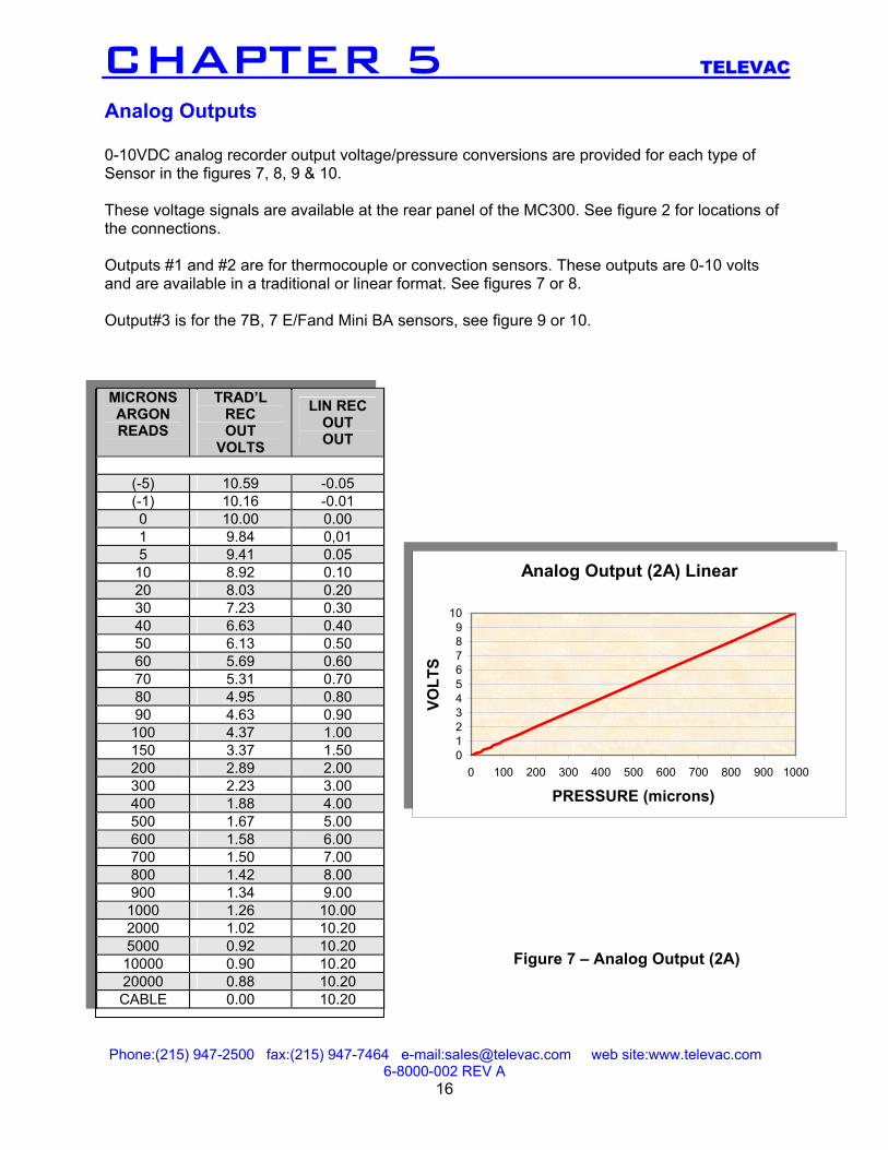
CHAPTER 5 TELEVAC Analog Outputs 0-10VDC analog recorder output voltage/pressure conversions are provided for each type of Sensor in the figures 7, 8, 9 & 10. These voltage signals are available at the rear panel of the MC300. See figure 2 for locations of the connections. Outputs #1 and #2 are for thermocouple or convection sensors. These outputs are 0-10 volts and are available in a traditional or linear format. See figures 7 or 8. Output#3 is for the 7B, 7 E/Fand Mini BA sensors, see figure 9 or 10. MICRONS ARGON READS
TRAD’L REC OUT
VOLTS
LIN REC OUT OUT
(-5) 10.59 -0.05 (-1) 10.16 -0.01 0 10.00 0.00 1 9.84 0,01 5 9.41 0.05
10 8.92 0.10 20 8.03 0.20 30 7.23 0.30 40 6.63 0.40 50 6.13 0.50 60 5.69 0.60 70 5.31 0.70 80 4.95 0.80 90 4.63 0.90 100 4.37 1.00 150 3.37 1.50 200 2.89 2.00 300 2.23 3.00 400 1.88 4.00 500 1.67 5.00 600 1.58 6.00 700 1.50 7.00 800 1.42 8.00 900 1.34 9.00
1000 1.26 10.00 2000 1.02 10.20 5000 0.92 10.20 10000 0.90 10.20 20000 0.88 10.20 CABLE 0.00 10.20
Analog Output (2A) Linear
0123456789
10
0 100 200 300 400 500 600 700 800 900 1000
PRESSURE (microns)
VOLT
S
Analog Output (2A) Linear
0123456789
10
0 100 200 300 400 500 600 700 800 900 1000
PRESSURE (microns)
VOLT
S
Figure 7 – Analog Output (2A)
Phone:(215) 947-2500 fax:(215) 947-7464 e-mail:[email protected] web site:www.televac.com 6-8000-002 REV A
17
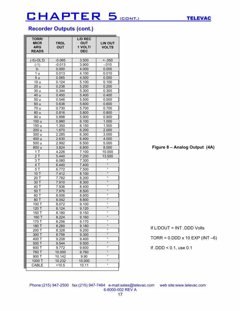
Figure 8 – Analog Output (4A)
CHAPTER 5 (CONT.) TELEVAC Recorder Outputs (cont.)
TORR/ MICR ARG
READS
TRDL OUT
L/D REC OUT
1 VOLT/ DEC
LIN OUT VOLTS
(-5)-OL’D -0.065 3.500 <-.050
(-1) -0.013 3.900 -.010 0- 0.000 4.000 0.000 1 u 0.013 4.100 0.010 5 u 0.065 4.500 0.050 10 u 0.124 5.100 0.100 20 u 0.238 5.200 0.200 30 u 0.344 5.300 0.300 40 u 0.450 5.400 0.400 50 u 0.546 5.500 0.500 60 u 0.638 5.600 0.600 70 u 0.730 5.700 0.700 80 u 0.816 5.800 0.800 90 u 0.898 5.900 0.900
100 u 0.980 6.100 1.000 150 u 1.350 6.150 1.500 200 u 1.670 6.200 2.000 300 u 2.285 6.300 3.000 400 u 2.630 6.400 4.000 500 u 2.992 6.500 5.000 800 u 3.824 6.800 8.000 1 T 4.226 7.100 10.000 2 T 5.440 7.200 13.500 3 T 6.080 7.300 “ 4 T 6.440 7.400 “ 5 T 6.772 7.500 “ 10 T 7.412 8.100 “ 20 T 7.782 8.200 “ 30 T 7.910 8.300 “ 40 T 7.936 8.400 “ 50 T 7.976 8.500 “ 60 T 8.006 8.600 “ 80 T 8.042 8.800 “
100 T 8.072 9.100 “ 120 T 8.124 9.120 “ 150 T 8.180 9.150 “ 160 T 8.224 9.160 “ 170 T 8.256 9.170 “ 180 T 8.280 9.180 “ 200 T 8.328 9.200 “ 300 T 8.756 9.300 “ 400 T 9.208 9.400 “ 500 T 9.544 9.500 “ 600 T 9.772 9.600 “ 760 T 10.000 9.760 “ 900 T 10.142 9.90 “
1000 T 10.232 10.000 “ CABLE >10.5 10.11 “
If L/DOUT = INT .DDD Volts TORR = 0.DDD x 10 EXP (INT –6) If .DDD < 0.1, use 0.1
Phone:(215) 947-2500 fax:(215) 947-7464 e-mail:[email protected] web site:www.televac.com 6-8000-002 REV A
18
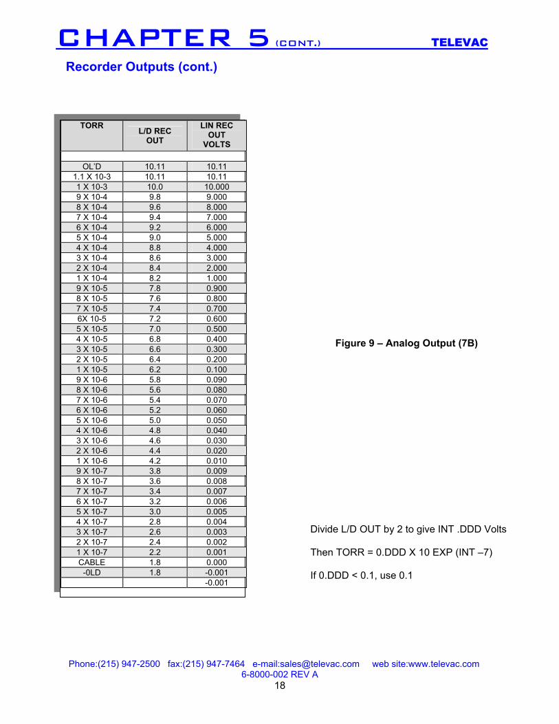
Figure 9 – Analog Output (7B)
CHAPTER 5 (CONT.) TELEVAC Recorder Outputs (cont.)
TORR L/D REC OUT
LIN REC OUT
VOLTS
OL’D 10.11 10.11 1.1 X 10⁻³ 10.11 10.11 1 X 10⁻³ 10.0 10.000 9 X 10⁻⁴ 9.8 9.000 8 X 10⁻⁴ 9.6 8.000 7 X 10⁻⁴ 9.4 7.000 6 X 10⁻⁴ 9.2 6.000 5 X 10⁻⁴ 9.0 5.000 4 X 10⁻⁴ 8.8 4.000 3 X 10⁻⁴ 8.6 3.000 2 X 10⁻⁴ 8.4 2.000 1 X 10⁻⁴ 8.2 1.000 9 X 10⁻⁵ 7.8 0.900 8 X 10⁻⁵ 7.6 0.800 7 X 10⁻⁵ 7.4 0.700 6X 10⁻⁵ 7.2 0.600 5 X 10⁻⁵ 7.0 0.500 4 X 10⁻⁵ 6.8 0.400 3 X 10⁻⁵ 6.6 0.300 2 X 10⁻⁵ 6.4 0.200 1 X 10⁻⁵ 6.2 0.100 9 X 10⁻⁶ 5.8 0.090 8 X 10⁻⁶ 5.6 0.080 7 X 10⁻⁶ 5.4 0.070 6 X 10⁻⁶ 5.2 0.060 5 X 10⁻⁶ 5.0 0.050 4 X 10⁻⁶ 4.8 0.040 3 X 10⁻⁶ 4.6 0.030 2 X 10⁻⁶ 4.4 0.020 1 X 10⁻⁶ 4.2 0.010 9 X 10⁻⁷ 3.8 0.009 8 X 10⁻⁷ 3.6 0.008 7 X 10⁻⁷ 3.4 0.007 6 X 10⁻⁷ 3.2 0.006 5 X 10⁻⁷ 3.0 0.005 4 X 10⁻⁷ 2.8 0.004 3 X 10⁻⁷ 2.6 0.003 2 X 10⁻⁷ 2.4 0.002 1 X 10⁻⁷ 2.2 0.001 CABLE 1.8 0.000
-0LD 1.8 -0.001 -0.001
Divide L/D OUT by 2 to give INT .DDD Volts Then TORR = 0.DDD X 10 EXP (INT –7) If 0.DDD < 0.1, use 0.1
Phone:(215) 947-2500 fax:(215) 947-7464 e-mail:[email protected] web site:www.televac.com 6-8000-002 REV A
19
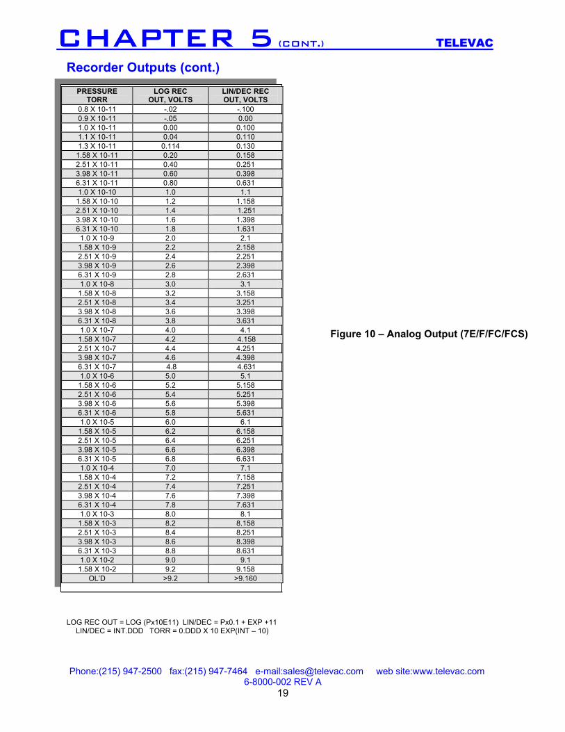
Figure 10 – Analog Output (7E/F/FC/FCS)
CHAPTER 5 (CONT.) TELEVAC Recorder Outputs (cont.)
PRESSURE TORR
LOG REC OUT, VOLTS
LIN/DEC REC OUT, VOLTS
0.8 X 10⁻¹¹ -.02 -.100 0.9 X 10⁻¹¹ -.05 0.00 1.0 X 10⁻¹¹ 0.00 0.100 1.1 X 10⁻¹¹ 0.04 0.110 1.3 X 10⁻¹¹ 0.114 0.130
1.58 X 10⁻¹¹ 0.20 0.158 2.51 X 10⁻¹¹ 0.40 0.251 3.98 X 10⁻¹¹ 0.60 0.398 6.31 X 10⁻¹¹ 0.80 0.631 1.0 X 10⁻¹⁰ 1.0 1.1
1.58 X 10⁻¹⁰ 1.2 1.158 2.51 X 10⁻¹⁰ 1.4 1.251 3.98 X 10⁻¹⁰ 1.6 1.398 6.31 X 10⁻¹⁰ 1.8 1.631
1.0 X 10⁻⁹ 2.0 2.1 1.58 X 10⁻⁹ 2.2 2.158 2.51 X 10⁻⁹ 2.4 2.251 3.98 X 10⁻⁹ 2.6 2.398 6.31 X 10⁻⁹ 2.8 2.631 1.0 X 10⁻⁸ 3.0 3.1
1.58 X 10⁻⁸ 3.2 3.158 2.51 X 10⁻⁸ 3.4 3.251 3.98 X 10⁻⁸ 3.6 3.398 6.31 X 10⁻⁸ 3.8 3.631 1.0 X 10⁻⁷ 4.0 4.1
1.58 X 10⁻⁷ 4.2 4.158 2.51 X 10⁻⁷ 4.4 4.251 3.98 X 10⁻⁷ 4.6 4.398 6.31 X 10⁻⁷ 4.8 4.631 1.0 X 10⁻⁶ 5.0 5.1
1.58 X 10⁻⁶ 5.2 5.158 2.51 X 10⁻⁶ 5.4 5.251 3.98 X 10⁻⁶ 5.6 5.398 6.31 X 10⁻⁶ 5.8 5.631 1.0 X 10⁻⁵ 6.0 6.1
1.58 X 10⁻⁵ 6.2 6.158 2.51 X 10⁻⁵ 6.4 6.251 3.98 X 10⁻⁵ 6.6 6.398 6.31 X 10⁻⁵ 6.8 6.631 1.0 X 10⁻⁴ 7.0 7.1
1.58 X 10⁻⁴ 7.2 7.158 2.51 X 10⁻⁴ 7.4 7.251 3.98 X 10⁻⁴ 7.6 7.398 6.31 X 10⁻⁴ 7.8 7.631 1.0 X 10⁻³ 8.0 8.1
1.58 X 10⁻³ 8.2 8.158 2.51 X 10⁻³ 8.4 8.251 3.98 X 10⁻³ 8.6 8.398 6.31 X 10⁻³ 8.8 8.631 1.0 X 10⁻² 9.0 9.1
1.58 X 10⁻² 9.2 9.158 OL’D >9.2 >9.160
LOG REC OUT = LOG (Px10E11) LIN/DEC = Px0.1 + EXP +11 LIN/DEC = INT.DDD TORR = 0.DDD X 10 EXP(INT – 10)
Phone:(215) 947-2500 fax:(215) 947-7464 e-mail:[email protected] web site:www.televac.com 6-8000-002 REV A
20
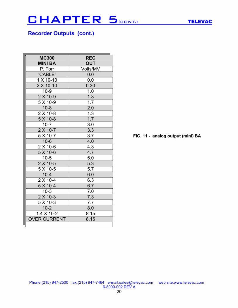
CHAPTER 5(CONT.) TELEVAC Recorder Outputs (cont.)
MC300 MINI BA
REC OUT
P. Torr Volts/MV “CABLE” 0.0 1 X 10⁻¹⁰ 0.0 2 X 10⁻¹⁰ 0.30
10-9 1.0 2 X 10⁻⁹ 1.3 5 X 10⁻⁹ 1.7
10-8 2.0 2 X 10⁻⁸ 1.3 5 X 10⁻⁸ 1.7
10-7 3.0 2 X 10⁻⁷ 3.3 5 X 10⁻⁷ 3.7
10-6 4.0 2 X 10⁻⁶ 4.3 5 X 10⁻⁶ 4.7
10-5 5.0 2 X 10⁻⁵ 5.3 5 X 10⁻⁵ 5.7
10-4 6.0 2 X 10⁻⁴ 6.3 5 X 10⁻⁴ 6.7
10-3 7.0 2 X 10⁻³ 7.3 5 X 10⁻³ 7.7
10-2 8.0 1.4 X 10⁻² 8.15
OVER CURRENT 8.15
FIG. 11 - analog output (mini) BA
Phone:(215) 947-2500 fax:(215) 947-7464 e-mail:[email protected] web site:www.televac.com 6-8000-002 REV A
21
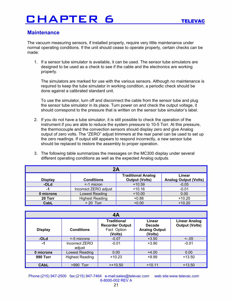
CHAPTER 6 TELEVAC Maintenance The vacuum measuring sensors, if installed properly, require very little maintenance under normal operating conditions. If the unit should cease to operate properly, certain checks can be made:
1. If a sensor tube simulator is available, it can be used. The sensor tube simulators are designed to be used as a check to see if the cable and the electronics are working properly.
The simulators are marked for use with the various sensors. Although no maintenance is required to keep the tube simulator in working condition, a periodic check should be done against a calibrated standard unit. To use the simulator, turn off and disconnect the cable from the sensor tube and plug the sensor tube simulator in its place. Turn power on and check the output voltage, it should correspond to the pressure that is written on the sensor tube simulator’s label.
2. If you do not have a tube simulator, it is still possible to check the operation of the
instrument if you are able to reduce the system pressure to 10-5 Torr. At this pressure, the thermocouple and the convection sensors should display zero and give Analog output of zero volts. The “ZERO” adjust trimmers at the rear panel can be used to set up the zero readings. If output still appears to respond incorrectly, a new sensor tube should be replaced to restore the assembly to proper operation.
3. The following table summarizes the messages on the MC300 display under several
different operating conditions as well as the expected Analog outputs.
2A
Display
Conditions Traditional Analog
Output (Volts) Linear
Analog Output (Volts) -OLd <-1 micron +10.59 -0.05
-1 Incorrect ZERO adjust +10.16 -0.01 0 microns Lowest Reading +10.00 0.00
20 Torr Highest Reading +0.88 +10.20 CabL > 20 Torr +0.00 +10.20
4A
Display
Conditions
Traditional Recorder Output
Fact Option (Volts)
Linear Decade
Analog Output (Volts)
Linear Analog Output (Volts)
-OLd <-5 microns -0.07 +3.50 <-.05 -1 Incorrect ZERO
adjust -0.01 +3.90 -0.01
0 microns Lowest Reading 0.00 +4.00 0.00 990 Torr Highest Reading +10.23 +9.99 +13.50
CAbL >990 Torr >+10.50 +10.11 +13.50
Phone:(215) 947-2500 fax:(215) 947-7464 e-mail:[email protected] web site:www.televac.com 6-8000-002 REV A
22
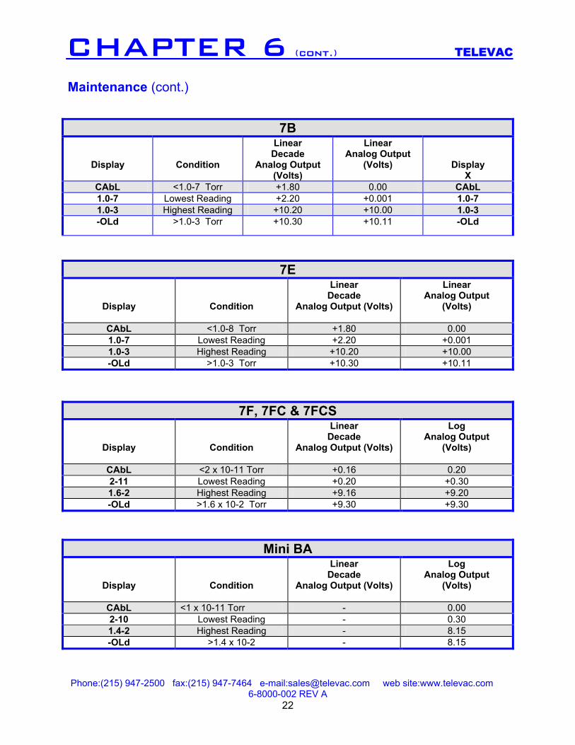
CHAPTER 6 (cont.) TELEVAC Maintenance (cont.)
7B
Display
Condition
Linear Decade
Analog Output (Volts)
Linear Analog Output
(Volts)
Display X
CAbL <1.0-7 Torr +1.80 0.00 CAbL 1.0-7 Lowest Reading +2.20 +0.001 1.0-7 1.0-3 Highest Reading +10.20 +10.00 1.0-3 -OLd >1.0-3 Torr +10.30 +10.11 -OLd
7E
Display
Condition
Linear Decade
Analog Output (Volts)
Linear Analog Output
(Volts)
CAbL <1.0-8 Torr +1.80 0.00 1.0-7 Lowest Reading +2.20 +0.001 1.0-3 Highest Reading +10.20 +10.00 -OLd >1.0-3 Torr +10.30 +10.11
7F, 7FC & 7FCS
Display
Condition
Linear Decade
Analog Output (Volts)
Log Analog Output
(Volts)
CAbL <2 x 10-11 Torr +0.16 0.20 2-11 Lowest Reading +0.20 +0.30 1.6-2 Highest Reading +9.16 +9.20 -OLd >1.6 x 10⁻² Torr +9.30 +9.30
Mini BA
Display
Condition
Linear Decade
Analog Output (Volts)
Log Analog Output
(Volts)
CAbL <1 x 10-11 Torr - 0.00 2-10 Lowest Reading - 0.30 1.4-2 Highest Reading - 8.15 -OLd >1.4 x 10⁻² - 8.15
Phone:(215) 947-2500 fax:(215) 947-7464 e-mail:[email protected] web site:www.televac.com 6-8000-002 REV A
23
CHAPTER 7 TELEVAC
CHAPTER 8
Calibration All Televac instrumentation is calibrated at the factory. No further calibration at the customer’s facility should be required. For a reliable re-calibration at a later date, it is necessary to have a reference standard vacuum system whose pressure is known very accurately. For such a calibration, the instrument, sensor tube and cable should be returned to Televac for re-certification. However, if the vacuum calibration certification is to be done at the customer’s facility, equipment of certifiable accuracy should be used by a knowledgeable electronics technician trained in vacuum calibration. Calibration Verification
1. Connect sensor to the known vacuum source. 2. Plug unit into 115VAC. Allow a minimum of 15 minutes warm-up.
3. Pump the system down to high vacuum. At 10-5 TORR verify that the thermocouple
or convection gauge reads at “0” VDC. If not, adjust the “zero” potentiometer.
4. Make a comparison table of indicated pressure on the instrument to that of the reference vacuum standard. The comparisons should be made typically at “0” (red line), 10, 100 and 1,000 millitorr and at 1, 10, 100, 500 and 760 Torr, (depending on the 2A or 7A gauge type).
5. For the 7B Cold Cathode calibration, pump the system down 10-3 Torr and verify
that the Cold Cathode sensor reads correctly. If not adjust the “10-3” potentiometer.
6. Verify readings at 10-4 Torr and lower pressures as required.
7. For the 7E/7F/7FC/7FCS Cold Cathode calibration, pump the system down to 10-5 and adjust the “10-5” potentiometer for a correct reading. Raise the pressure to 10-3 and adjust the “10-3” potentiometer for the correct reading. It is important to do the 10-5 adjustment first since it affects the 10-3 reading also.
8. For the Mini BA calibration, pump the system down to 1 X 10⁻⁵ Torr. From the front
panel set up button menu choose “SENS” and use the up/down arrows to change the sensitivity setting. If the instrument reads lower than 1 X 10⁻⁵, decrease the sensitivity setting slightly and press “TST/OP”. If the reading is now too high, increase the “SENS” setting and re-check the reading.
Phone:(215) 947-2500 fax:(215) 947-7464 e-mail:[email protected] web site:www.televac.com 6-8000-002 REV A
24
CHAPTER 10
CHAPTER 9 TELEVAC Troubleshooting Troubleshooting of the circuit or components is similar to any industrial electrical equipment, i.e., checking for circuit continuity, shorts, grounds, resistors, values, etc. NOTE: If, after doing some or all of the above, the unit is still inoperative, return to factory for repair. Specifications Range Power See table in Chapter 1 115 VAC, 230 VAC (optional) Calibration Medium Oper. Temp. Dry air, (or nitrogen) +15 ° to +50° C Frequency Fuse 60 Hz or 50 Hz Internal Display/Output Relay Contacts Digital/analog 5 Amps @ 230 VAC 3 digits, 0-10 Volts Weight (instrument 5 lbs. Max. exclusive of sensors and cables
Phone:(215) 947-2500 fax:(215) 947-7464 e-mail:[email protected] web site:www.televac.com 6-8000-002 REV A
25
CHAPTER 12 TELEVAC
Dimensions Warranty The Fredericks Company warrants all instruments and components of its manufacture to be free of defects in materials and workmanship. Our obligation under this warranty is limited to servicing or adjusting any instrument returned to us and replacing any part, except those specifically exempt from this guarantee, which shall within one year after delivery to the original purchaser be returned to us with transportation charges prepaid, and which our examination should disclose to our satisfaction to have been defective. Those portions specifically exempt from this guarantee are gauge tubes, batteries as well as meters, which have been dissembled or physically damaged. The Fredericks Company does not assume any other obligation than that stated in this warranty nor does it authorize any person to assume for them any liability in connection with the sale, service or use of the Fredericks Company’s instruments.
CHAPTER 11 TELEVAC
Phone:(215) 947-2500 fax:(215) 947-7464 e-mail:[email protected] web site:www.televac.com 6-8000-002 REV A
26
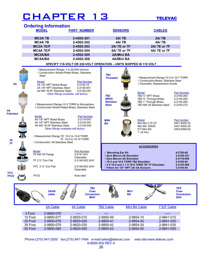
CHAPTER 13 TELEVAC
√ Measurement Range-10-3 to 10-7 TORR √ Construction-Brass, Stainless Steel √ Cleanable, Replacement Anode Model Part Number 7B2 ¾” NPT Brass 2-2100-263 7B2 ¾” Through Brass 2-2100-264 7B2 1” Through Brass 2-2100-265 7B2 NW 25 Stainless Steel 2-2100-272 Model Part number Mini BA 2.75 CF 3451-8305-25Mini BA NW25 3451-8305-35ETI Mini BA 1” str thru
3452-8306-05
2A
7B2 Threaded
7B2 NW25 StainlessSteel
√ Measurement Range 7E: 10-2 to 10-8 TORR 7F: 10-2 to 10-10 TORR √ Construction- All Stainless Steel Model Part Number 7E NW 25 Flange 2-2141-031 Cleanable 7F 2 ¾” Con Flat 2-2145-052 UHV 7FC 2 ¾” Con Flat 2-2146-053 UHV Cleanable 7FCS Auto-start
2A/4A cable
7B2 Coax
ConnectorsMHV
7E/F Coax ConnectorsSHV
MINI BA
Mini BA
7E 7F
7FC/7FCS
Ordering Information MODEL PART NUMBER SENSORS CABLES
MC2A 7B 2-4502-301 2A/ 7B 2A/ 7B MC4A 7B 2-4502-302 4A/ 7B 4A/ 7B
MC2A 7E/F 2-4502-303 2A/ 7E or 7F 2A/ 7E or 7F MC4A 7E/F 2-4502-304 4A/ 7E or 7F 4A/ 7E or 7F MC2A/BA 2-4502-305 2A/Mini BA MC4A/BA 2-4502-306 4A/Mini BA
SPECIFY 110-VOLT OR 220-VOLT OPERATION – UNITS SHIPPED IN 110 VOLT
√ Measurement Range–1 to 20,000 microns √ Construction–Nickel-Plated Brass, Stainless Steel
Model Part Number 2A 1/8” NPT Nickel Brass 2-2100-10 2A 1/8” NPT Stainless Steel 2-2126-001 2a NW 16 KF Stainless Steel 2-2126-030
Other fittings available- call factory
2A Cable 4A Cable 7B2 Cable Mini BA Cable 7 E/F Cable
3 Foot 2-9800-076 ---- ---- ----- 10 Foot 2-9800-077 2-9820-010 2-9800-09 2-9854-10 2-9841-010 20 Foot 2-9800-078 2-9820-020 2-9800-41 2-9854-20 2-9841-020 35 Foot 2-9800-079 2-9820-035 2-9800-42 2-9854-35 2-9841-035 50 Foot 2-9800-080 2-9820-050 2-9800-43 2-9854-50 2-9841-050
√ Measurement Range-10-3 TORR to Atmosphere √ Construction-Nickel-Plated Brass, Stainless Steel Model Part Number 4A 1/8” NPT Nickel Brass 2-2119-001 4A 1/8” NPT Stainless Steel 2-2120-001 4A NW 16 KF Stainless Steel 2-2120-030
Other fittings available-call factory
4A Patented
ACCESSORIES √ Mounting Ear Kit 6-2700-60 √ Zero Micron 2A Simulator 2-2100-237 √ Zero Micron 4A Simulator 2-2119-000 √ 10-3 and 10-5 TORR 7B2 Simulator 2-2100-93 √ 2 X 10⁻⁴ and 1.1 X 10⁻⁵ TORR 7E/ 7F Simulator 2-2145-000 √ Filters for 1/8” NPT 2A/ 4A Sensors 2-2100-50
Related Documents


