PWM Embedded 3-Channel Constant Current LED Sink Driver for RGB LED Clusters ©Macroblock, Inc. 2012 Floor 6-4, No.18, Pu-Ting Rd., Hsinchu, Taiwan 30077, ROC. TEL: +886-3-579-0068, FAX: +886-3-579-7534 E-mail: [email protected] - 1 - Macroblock Preliminary Datasheet MBI6030 July 2012, V3.01 Shrink SOP GP: SSOP16L-150-0.64 QFN GFN: QFN24L-4*4-0.5 Features 3-channel constant current LED sink driver for RGB LED clusters Constant output current range per channel: 5~150mA Excellent output current accuracy, - Between channels: <±3% (max.); - Between ICs: <±6% (max.) Sustaining voltage at output channels: 40V (max.) Embedded 16-bit PWM generator - Gray scale clock generated by the embedded oscillator - S-PWM technology Two selectable modes to trade off between image quality and transmission bandwidth - 16-bit gray scale mode - 10-bit gray scale mode (with optional 6-bit dot correction) Reliable data transmission - Daisy-chain topology - Two-wire only transmission interface - Clock regeneration - Built-in buffer for long distance transmission Supply voltage range (V DDH ): 7~30V Embedded voltage regulator Selectable polarity reversion to drive high-power drivers or MOS RoHS-compliant packages Application Architectural lighting Mesh display or LED strip Neon light replacement Channel letter Remote PWM generator Ihr autorisierter Distributor Neumüller Elektronik GmbH [email protected] Neumüller Elektronik GmbH | Gewerbegebiet Ost 7 | 91085 Weisendorf | +49 9135 73666-0 | www.neumueller.com | [email protected]

Welcome message from author
This document is posted to help you gain knowledge. Please leave a comment to let me know what you think about it! Share it to your friends and learn new things together.
Transcript

PWM Embedded 3-Channel Constant Current LED Sink Driver for RGB LED Clusters
©Macroblock, Inc. 2012 Floor 6-4, No.18, Pu-Ting Rd., Hsinchu, Taiwan 30077, ROC.
TEL: +886-3-579-0068, FAX: +886-3-579-7534 E-mail: [email protected] - 1 -
Macroblock Preliminary Datasheet MBI6030
July 2012, V3.01
Shrink SOP
GP: SSOP16L-150-0.64
QFN
GFN: QFN24L-4*4-0.5
Features
3-channel constant current LED sink driver for RGB LED clusters
Constant output current range per channel: 5~150mA
Excellent output current accuracy,
- Between channels: <±3% (max.);
- Between ICs: <±6% (max.)
Sustaining voltage at output channels: 40V (max.)
Embedded 16-bit PWM generator
- Gray scale clock generated by the embedded oscillator
- S-PWM technology
Two selectable modes to trade off between image quality and transmission
bandwidth
- 16-bit gray scale mode
- 10-bit gray scale mode (with optional 6-bit dot correction)
Reliable data transmission
- Daisy-chain topology
- Two-wire only transmission interface
- Clock regeneration
- Built-in buffer for long distance transmission
Supply voltage range (VDDH): 7~30V
Embedded voltage regulator
Selectable polarity reversion to drive high-power drivers or MOS
RoHS-compliant packages
Application
Architectural lighting
Mesh display or LED strip
Neon light replacement
Channel letter
Remote PWM generator
Ihr autorisierter Distributor Neumüller Elektronik GmbH [email protected]
Neumüller Elektronik GmbH | Gewerbegebiet Ost 7 | 91085 Weisendorf | +49 9135 73666-0 | www.neumueller.com | [email protected]

PWM Embedded 3-Channel Constant Current LED Sink Driver for RGB LED Cluster
July 2012, V3.01 - 2 -
MBI6030
Product Description
MBI6030 is a 3-channel, constant current, PWM-embedded LED sink driver for RGB LED cluster. MBI6030 provides
constant current ranging from 5mA to 150mA for each output channel and sustains 40V at output channels. The
constant output current of each output channel is adjustable with three corresponding external resistors.
With Scrambled-PWM (S-PWM) technology, MBI6030 enhances pulse width modulation by scrambling the “on” time
into several “on” periods, so that MBI6030 reduces the data transmission bandwidth at the same gray scale
performance. MBI6030 provides two selectable gray scale modes to trade off between image quality and
transmission: 16-bit gray scale mode and 10-bit gray scale mode.16-bit gray scale mode provides 65,536 gray
scales for each LED to enrich the color. Furthermore, 10-bit gray scale mode provides 1,024 gray scales. Subject to
10-bit gray scale mode, 6-bit dot correction may adjust each LED by 64-step gain to compensate the LED
brightness.
Furthermore, MBI6030 features a two-wire transmission interface to make cluster-to-cluster connection easier. To
improve the transmission quality, MBI6030 provides clock regeneration to recover the clock duty cycle to avoid
signal distortion after long-distance transmission.
MBI6030 allows wide supply voltage range (VDDH) from 7V to 30V, which is suitable for 12V or 24V systems.
Additionally, MBI6030 preserves selectable polarity reversion to driver external high-power drivers as a PWM
controller.
Ihr autorisierter Distributor Neumüller Elektronik GmbH [email protected]
Neumüller Elektronik GmbH | Gewerbegebiet Ost 7 | 91085 Weisendorf | +49 9135 73666-0 | www.neumueller.com | [email protected]

PWM Embedded 3-Channel Constant Current LED Sink Driver for RGB LED Cluster
July 2012, V3.01 - 3 -
MBI6030
MBI6030GP
Top View MBI6030GFN
Top View
Pin Configuration
Terminal Description
Pin No. Pin Name Function GP GFN 1 6 GND Ground terminal
2 7 POL
Input terminal for selecting output polarity. With internal pull-up resistor connected to CA. High/NC: normal mode to drive low-active regulators or PMOS Low: output reversed to work as a PWM controller to drive high-active regulators or NMOS
3,4,5 8,9,10 R-EXTA,B,C Input terminal for setting output current by connecting to an external resistor
14,13,12 23,22,21 CB,OUTA, Output terminals for constant current output
6, 11 2,3,4,5,11,14, 15,16,17,20 NC Keep unconnected
Internal pulled-down 7 12 CKI Input terminal for clock input 8 13 SDI Input terminal for serial data input 10 19 CKO Output terminal for clock output 9 18 SDO Output terminal for serial data output 15 24 CA Connecting a capacitor to GND to enhance the stability of CA. 16 1 VDDH High supply voltage terminal
- - Thermal Pad
Heat dissipation pad* Please connect to GND
*The desired thermal conductivity will be improved on condition that a heat-conducting copper foil on PCB is
soldered with thermal pad.
GND VDDHPOL
NC
SDI
1
2
3
4
8
7
6
5
CKI
R-EXTA
SDO
13
14
15
16
NC10
11
12
OUTA
OUTB
OUTC
CKO
R-EXTB
R-EXTC
9
CA2324 22 21 20 19
1413
15
16
1718
87 9 10 11 12
56
4
3
21
ThermalPad
VDDH
NC
NC
NC
NC
GND
SDO
NC
NC
NC
NC
SDI
Ihr autorisierter Distributor Neumüller Elektronik GmbH [email protected]
Neumüller Elektronik GmbH | Gewerbegebiet Ost 7 | 91085 Weisendorf | +49 9135 73666-0 | www.neumueller.com | [email protected]

PWM Embedded 3-Channel Constant Current LED Sink Driver for RGB LED Cluster
July 2012, V3.01 - 4 -
MBI6030
Typical Application Circuit
Note:
1. The TVS1 and TVS3, transient voltage suppressors, are used to suppress the overshoot, undershoot and ESD.
2. C1~C4 are required. The values of these capacitors are reference only. Tantalum and ceramic capacitors are
recommended.
3. Please locate the C1, C2, and TVS1 as close to the pin16, the C4 as close to pin15 as possible.
DC/DC Converter
GND
VDDH OUTA OUTB OUTC
CKI
SDI
R-EXTA R-EXTB R-EXTC
CKO
SDO
NC
NCPOL
CA
MBI6030GP
R5R4R3
C40.1uF
1
2
7
8
6 3 4 5
16 14 13 1215
11
10
9connect to CA
CKISDI
C310uFTVS2
TVS3 TVS4
GNDCKOSDOGND
VIN VOUT
R2
R1
VDS
VLED
R80 Ω
J1 J2
GND GND
C110uFTVS1
C20.1uF
connect to CA
Ihr autorisierter Distributor Neumüller Elektronik GmbH [email protected]
Neumüller Elektronik GmbH | Gewerbegebiet Ost 7 | 91085 Weisendorf | +49 9135 73666-0 | www.neumueller.com | [email protected]

PWM Embedded 3-Channel Constant Current LED Sink Driver for RGB LED Cluster
July 2012, V3.01 - 5 -
MBI6030
Block Diagram
IO Regulator
OUTA OUTB OUTC
Com
parators C
16
16
Com
parators B
16
16
Com
parators A
16
Gray scale data
register A
16
Oscillator
PWM Counter
R-EXTAR-EXTBR-EXTC
POL
CA
SDO SDI
CKI
Shift Register
CKO
Decoder & Data Dispatcher
Dot correction
data register A
Gray scale data
register B
Dot correction
data register B
Gray scale data
register C
Dot correction
data register C
VDDH CA Voltage Regulator
470K
Ihr autorisierter Distributor Neumüller Elektronik GmbH [email protected]
Neumüller Elektronik GmbH | Gewerbegebiet Ost 7 | 91085 Weisendorf | +49 9135 73666-0 | www.neumueller.com | [email protected]

PWM Embedded 3-Channel Constant Current LED Sink Driver for RGB LED Cluster
July 2012, V3.01 - 6 -
MBI6030
Equivalent Circuits of Inputs and Outputs
POL terminal
OUTA, OUTB , OUTC R-EXTA, R-EXTB, R-EXTC terminal CKO, SDO terminal
CKI, SDI terminal
VDDH, CA terminal
VDDL
POL
CA VDDL
CKI,SDI
CA
VDDL
R-EXTAR-EXTBR-EXTC
OUTAOUTBOUTC
CA
VDDL
CKO,SDO
CA
VDDL
VDDH
CA
Ihr autorisierter Distributor Neumüller Elektronik GmbH [email protected]
Neumüller Elektronik GmbH | Gewerbegebiet Ost 7 | 91085 Weisendorf | +49 9135 73666-0 | www.neumueller.com | [email protected]

PWM Embedded 3-Channel Constant Current LED Sink Driver for RGB LED Cluster
July 2012, V3.01 - 7 -
MBI6030
Maximum Ratings
Characteristic Symbol Rating Unit
Supply Voltage VDDH 0~35 V
Sustaining Voltage at CKI, SDI, E-GCLK, POL Pins VIN -0.4~VCA+0.4 V
Sustaining Voltage at CKO, SDO Pins VOUT -0.4~VCA+0.4 V
Sustaining Voltage at OUTA ~ OUTC VDS -0.5~+40 V
Output Current per Output Channel IOUT +170 mA
GND Terminal Current IGND 480 mA
Power Dissipation (On 4 Layer PCB, Ta=25°C)*
MBI6030GP PD 1.85 W
MBI6030GFN PD 2.97 W
Thermal Resistance (By simulation, on 4 Layer PCB)*
MBI6030GP Rth(j-a)
67.44 °C/W
MBI6030GFN 42.10 °C/W
Junction Temperature Tj,max 150 °C
Storage Temperature Tstg -55~+150 °C
ESD Rating
Human Body Mode (MIL-STD-883G Method 3015.7)
HBM Class 3A (4000V ~ 7999V) -
Machine Mode (JEDEC EIA/JESD22-A115)
MM Class C (≧400V) -
*The PCB size is 76.2mm*114.3mm in simulation. Please refer to JEDEC JESD51.
Note: The performance of thermal dissipation is strongly related to the size of thermal pad, thickness and layer
numbers of the PCB. The empirical thermal resistance may be different from simulative value. Users should plan for
expected thermal dissipation performance by selecting package and arranging layout of the PCB to maximize the
capability.
Ihr autorisierter Distributor Neumüller Elektronik GmbH [email protected]
Neumüller Elektronik GmbH | Gewerbegebiet Ost 7 | 91085 Weisendorf | +49 9135 73666-0 | www.neumueller.com | [email protected]

PWM Embedded 3-Channel Constant Current LED Sink Driver for RGB LED Cluster
July 2012, V3.01 - 8 -
MBI6030
Electrical Characteristics (Ta=25°C)
Characteristic Symbol Condition Min. Typ. Max. Unit
Voltage Regulator Input Voltage VDDH - 7 - 30 V
CA Output Voltage VCA - 4.5 5 5.5 V
Sustaining Voltage at OUT Ports VDS,Max OUTA ~ OUTC =Off - - 40 V
Output Current IOUTRefer to “Test Circuit for
Electrical Characteristics” 5 - 150 mA
Driving Current IOH CKO, SDO at VO=3.5V -8.5 - -15.5 mA
IOL CKO, SDO at VO=1.0V 8 - 15 mA
Output Leakage Current IOUT VDS=40V, all channels turn off - - 0.2 µA
Current Skew (Channel) dIOUT1 IOUT=19.9mAVDS=1.0V Rext=20Ω - ±1.5 ±3.0 %
Current Skew (IC) dIOUT2 IOUT=19.9mAVDS=1.0V Rext=20Ω - ±3.0 ±6.0 %
Output Current vs. Output Voltage Regulation %/dVDS VDS within 1.0 V and 3.0V - ±0.1 ±0.5 % / V
Input Voltage of CKI, SDI Pins
“H” level VIH - 0.75xVCA - VCA V
“L” level VIL - GND - 0.26xVCA V
Output Voltage of CKO, SDO Pins
“H” level VOH IOH=-1.0mA - - 4.5 V
“L” level VOL IOL=+1.0mA 0.2 - - V Voltage at R-EXTA, R-EXTB, R-EXTC Pins VREXT Rext=20Ω 0.376 0.4 0.424 V
Threshold Temperature for Thermal Shutdown ** TX
POL=highRext=80Ω - 155 - °C
POL=low
Threshold Temperature for Thermal Shutdown Recovering ** TRECV
POL=highRext=80Ω - 130 - °C
POL=low Pull-up Resistor at POL Pin RIN(up) - - 470 - KΩ
Supply Current ***
IDD(on) 1 Rext=20Ω, CKI, SDI=Low, CKO, SDO=NC,
OUTA ~ OUTC =On
2.0 - 5.5mA
IDD(off) 2
Rext=6.8Ω, CKI, SDI=Low, CKO, SDO=NC,
OUTA ~ OUTC =Off mA
*One channel turns on.
**Guaranteed by design.
*** The supply current may vary with the loading conditions.
Note: The above operation range is defined based on the ambient temperature (Ta=25°C). However, the
recommended operating temperature range is from -45°C to +85°C, but the operation range may vary accordingly.
Ihr autorisierter Distributor Neumüller Elektronik GmbH [email protected]
Neumüller Elektronik GmbH | Gewerbegebiet Ost 7 | 91085 Weisendorf | +49 9135 73666-0 | www.neumueller.com | [email protected]

PWM Embedded 3-Channel Constant Current LED Sink Driver for RGB LED Cluster
July 2012, V3.01 - 9 -
MBI6030
Test Circuit for Electrical Characteristics
Ihr autorisierter Distributor Neumüller Elektronik GmbH [email protected]
Neumüller Elektronik GmbH | Gewerbegebiet Ost 7 | 91085 Weisendorf | +49 9135 73666-0 | www.neumueller.com | [email protected]

PWM Embedded 3-Channel Constant Current LED Sink Driver for RGB LED Cluster
July 2012, V3.01 - 10 -
MBI6030
Switching Characteristics Characteristic Symbol Condition Min. Typ. Max. Unit
Setup Time SDI-CKI↓ tS(D)
TA=25°C VDDH=12V VDS=1V VIH=4.5V VIL=0.5V Rext=20Ω (IOUT=20mA)RL=200Ω CL=10pF
5 - - ns Hold Time SDI-CKI↓ tH(D) 5 - - ns
Propagation Delay Time CKI – CKO tP1 - 25 - ns CKO↑ - SDO tP2 - 25 - ns
Pulse Width CKO tw(O) 45 77 90 ns CKI tw(I) 17 - - ns
Output Rise Time of Output Ports
CKO/SDO tcr - 2.5 - ns
OUTA ~ OUTC torh* - 60 - ns torl* - 125 - ns
Output Fall Time of Output Ports
CKO/SDO tcf - 2.5 - ns
OUTA ~ OUTC tofh* - 40 - ns tofl* - 135 - ns
Frequency CKI** FCKI 0.08 - 8 MHz
GCLK High-frequency FGCLK 8.1 9.0 9.9 MHzLow-frequency FGCLK 4.0 4.5 5.0 MHz
Maximum CKI Rise Time tr - - 500 ns Maximum CKI Fall Time tf - - 500 ns *torh, tofh are for the high-frequency GCLK. torl, tofl are for the low-frequency GCLK. **The maximum frequency may be limited by different application conditions. Please refer to the application note for
details. Test Circuit for Switching Characteristics
Function Generator
LIHI V,V
GND
POL
R-EXTB
R-EXTA
R-EXTC
NC
CKI
SDI
VDDH
CA
OUTA
OUTB
OUTC
NC
CKO
SDO
Rext
Rext
Rext
VDS
VDDH
IDD
VLED
CL RL CL CLRL RL
CL CL
C20.1µF
C110µF
C410µF
C310µF
Ihr autorisierter Distributor Neumüller Elektronik GmbH [email protected]
Neumüller Elektronik GmbH | Gewerbegebiet Ost 7 | 91085 Weisendorf | +49 9135 73666-0 | www.neumueller.com | [email protected]

PWM Embedded 3-Channel Constant Current LED Sink Driver for RGB LED Cluster
July 2012, V3.01 - 11 -
MBI6030
Timing Waveform
CKO
90%
10%
90%
10%
tOF tOR
SDO
90%
10%
90%
10%
tcftcr
CKI
1/FCKI
tw(I)
SDI
tH(D)tS(D)
CKO
tw(O)
SDO
tP1
tP2
90%
10%
90%
10%
tofhtorh
CKI90%
10%
90%
10%
tftr
90%
10%
90%
10%
tofltorl
GCLK
1/FGCLK
OUTA~OUTC
OUTA~OUTC
Data 1
Data 1
Ihr autorisierter Distributor Neumüller Elektronik GmbH [email protected]
Neumüller Elektronik GmbH | Gewerbegebiet Ost 7 | 91085 Weisendorf | +49 9135 73666-0 | www.neumueller.com | [email protected]

PWM Embedded 3-Channel Constant Current LED Sink Driver for RGB LED Cluster
July 2012, V3.01 - 12 -
MBI6030
Principle of Operation
MBI6030 provides SPI-like interface (CKI, SDI), a two-wire transmission interface, to address the data, so that
MBI6030 receives the data directly without a latch command. The sequence of operation should follow the steps
below:
Step 1. Send the dot correction data (Optional)
Step 2. Send the gray scale data
MBI6030 receives the data packet containing targeted gray scale data from the controller, and turns on the output
channels according to the gray scale data.
Control Interface: SPI-Like Interface (CKI, SDI) MBI6030 adopts the SPI-like interface (CKI/SDI). By SPI-like interface, MBI6030 samples the data (SDI) at the
falling edge of the clock (CKI).The following waveforms is the example of the SPI-like interface.
Ihr autorisierter Distributor Neumüller Elektronik GmbH [email protected]
Neumüller Elektronik GmbH | Gewerbegebiet Ost 7 | 91085 Weisendorf | +49 9135 73666-0 | www.neumueller.com | [email protected]

PWM Embedded 3-Channel Constant Current LED Sink Driver for RGB LED Cluster
July 2012, V3.01 - 13 -
MBI6030
The Structure of Data Packet MBI6030’s data packet contains three parts:
1. Prefix:
The prefix is a symbol of “Silent-to-Reset”, i.e. a time period for MBI6030 to distinguish two data packets. During
the prefix, both CKI and SDI should be tied-low and stop for more than 44 CKI cycles.
2. Header:
The header defines the cascaded IC numbers and also contains a command to decide the data type.
3. Data:
This is the data for each IC. It may be gray scale data or dot correction data.
Structure of a data packet:
Time-Out Reset for Transmission Abort Time-out reset is to prevent ICs from misreading during the data transmission. The time-out period is 23~44 CKI cycles. If the CKI is tied-low for more than the preset period, MBI6030 may identify the wires as disconnection. To prevent from misreading, MBI6030 will ignore the present input data and continuously show the previous image data until the next image data is correctly recognized. That is, MBI6030 may recognize the input data as a new packet during the CKI time-out period (23~44 CKI cycles). To prevent from time-out, users should limit the period shorter than 23 CKI cycles. The illustration is as below:
The Prefix in the Beginning of a Data Packet MBI6030 identifies the data as a new data packet after time-out, so the prefix in the beginning of a data packet
should be larger than 44 CKI cycles.
If both CKI and SDI are tied-low and stop for more than 44 CKI time-out cycles, MBI6030 will start to check the valid
command of the next data packet. The prefix between two data packets helps MBI6030 identify the data packet
correctly. The following timing diagram illustrates the interval between two data packets in 16-bit gray scale mode.
Prefix Header Data
Ihr autorisierter Distributor Neumüller Elektronik GmbH [email protected]
Neumüller Elektronik GmbH | Gewerbegebiet Ost 7 | 91085 Weisendorf | +49 9135 73666-0 | www.neumueller.com | [email protected]

PWM Embedded 3-Channel Constant Current LED Sink Driver for RGB LED Cluster
July 2012, V3.01 - 14 -
MBI6030
Setting the Data Types by the Command MBI6030 provides three kinds of commands and input data types shown as the table below:
Command H[5:0] Data Type 6’b11 111s 16-bit gray scale data 6’b10 101s 10-bit gray scale data 6’b10 011s 6-bit dot correction data
bit “s”: 1, high-frequency GCLK (9MHz±10%)
bit “s”: 0, low-frequency GCLK (4.5MHz±10%)
Once MBI6030 receives the SDI=1 (1’b1), MBI6030 will start to check if the data is a valid command or not. If the
6-bit data is a valid command, the driver will latch the specific data according to the protocol. If the 6-bit data is not a
valid command, MBI6030 will wait for another SDI=1 (1’b1) to check the validity of the next command. GCLK Frequency MBI6030 is embedded with an oscillator as the clock of PWM counter (GCLK) to turn on output ports according to
the gray scale data sent from the system controller.
When bit “s” is “1”, MBI6030 works at high-frequency GCLK; when bit “s” is “0”, MBI6030 works at low-frequency
GCLK. The high-frequency GCLK is 9MHz±10%, and the low–frequency GCLK is 4.5MHz±10%.
Low-frequency GCLK is recommended for IOUT>40mA, or when MBI6030 drives external high-power LED drivers,
because lower GCLK frequency and switching speed is more suitable for these two applications. In contrast,
high-frequency is suitable for IOUT<40mA to enhance the visual refresh rate.
Ihr autorisierter Distributor Neumüller Elektronik GmbH [email protected]
Neumüller Elektronik GmbH | Gewerbegebiet Ost 7 | 91085 Weisendorf | +49 9135 73666-0 | www.neumueller.com | [email protected]

PWM Embedded 3-Channel Constant Current LED Sink Driver for RGB LED Cluster
July 2012, V3.01 - 15 -
MBI6030
Dot Correction MBI6030 also provides 6-bit dot correction in 10-bit gray scale mode. Dot correction control helps compensate LED
brightness.
For valid dot correction control, users have to program dot correction data before sending gray scale data.
10-bit gray scale with 6-bit dot correction:
The following is the equation for the duty cycle of output in 10-bit gray scale mode. For 6-bit dot correction, the
default value of dot correction data is 63.
According to the above equation, the following table shows the examples:
Example: Dot correction data The ratio of output turn-on time
0 1/64 x gray scale data 1 2/64 x gray scale data 2 3/64 x gray scale data . . .
.
.
. 63 64/64 x gray scale data
The algorithm of PWM counting with dot correction data
When adopting 6-bit dot correction in 10-bit gray scale mode, MBI6030 will has a 16-bit PWM period, which is also
scrambled into 64 segments. The duty ratio of each segment is decided by the 10-bit gray scale data, and the
numbers of turned-on segments is decided by the 6-bit dot correction data. The turned-on segments are distributed
evenly to increase the visual refresh rate.
The chart below shows the PWM output.
Assume:
the 10-bit grayscale data=1023,
6-bit dot correction data=31 (50%).
The 16-bit PWM output period is scramble into 64 segments,
but only 32 segments of the 64 segments are turned on with ~99.9% (1023/1024) duty ratio.
10-bit gray scale data = 1,023, 6-bit dot correction data = 31
3 5
Once of 16-bit PWM Counting
1 63
1024 GCLKs 10-bit Gray Scale Data with
6-bit Dot Correction Data
Ihr autorisierter Distributor Neumüller Elektronik GmbH [email protected]
Neumüller Elektronik GmbH | Gewerbegebiet Ost 7 | 91085 Weisendorf | +49 9135 73666-0 | www.neumueller.com | [email protected]

PWM Embedded 3-Channel Constant Current LED Sink Driver for RGB LED Cluster
July 2012, V3.01 - 16 -
MBI6030
6-bit Dot Correction Data
For 6-bit dot correction data, each word is 10 bits. Each MBI6030 needs 3 words (3x10=30 bits) for the dot
correction data of each output channel of one MBI6030. However, each dot correction data has only 6 bits, and the
first 4 bits of each word should be set as “0”. Prior to the dot correction data, there is a 30-bit header. The data
format is shown below:
Prefix
Both CKI and SDI should be tied-low and stop for more than 44 CKI cycles.
30-bits header Bit Definition Value Function 29:24 H[5:0] 10011s The command of 6-bit dot correction data 23:20 X4[3:0] 0000 Must be 0 19:10 A[9:0] 0000000000 Address data. Always send 10’b 0000000000
9:0 L[9:0] N-1 N=Number of IC in series Set the number of IC in series
30-bit dot correction data Bit Definition Value Function
29: 20 Z[3:0]~CN[5:0] 10b’0000000000~
10b’0000111111
6-bit x 1 channel dot correction data of the Nth
MBI6030. The data of OUTC is sent first. The 4 MSB bits, Z[3:0], are not used, and please send 4b’0000.
19:0 Z[3:0]~BN[5:0]...AN[5:0] The range of the data value is the same as the previous 10 bits.
6-bit x 2 channels dot correction data of the Nth MBI6030. The data format is the same as the prior 10 bits.
The dot correction data of the last IC is sent first, followed by the previous ICs, and the first IC’s dot correction data is
sent in the end of the packet. The ratio of output turn-on time will be (dot correction data+1)/256 x gray scale data.
Ihr autorisierter Distributor Neumüller Elektronik GmbH [email protected]
Neumüller Elektronik GmbH | Gewerbegebiet Ost 7 | 91085 Weisendorf | +49 9135 73666-0 | www.neumueller.com | [email protected]

PWM Embedded 3-Channel Constant Current LED Sink Driver for RGB LED Cluster
July 2012, V3.01 - 17 -
MBI6030
Gray Scale MBI6030 provides two gray scale modes: 16-bit gray scale mode and 10-bit gray scale mode by adopting S-PWM or
conventional PWM algorithm respectively. MBI6030 adopts S-PWM technology in 16-bit gray scale mode to
scramble the 16-bit PWM to 64 segments, so that the visual refresh rate can be increased. For example, with
S-PWM, if PWM clock (GCLK) frequency is around 9MHz, and therefore, the visual refresh rate of 16-bit gray scale
mode will be increased to: 9MHz/65536x64=8,789Hz
On the other hand, MBI6030 provides 10-bit gray scale mode by conventional PWM. In 16-bit gray scale mode,
MBI6030 achieves 65,536 gray scales for each LED, and in 10-bit gray scale mode, MBI6030 achieves 1,024 gray
scales. The following illustrations explain the PWM counting by S-PWM and conventional PWM algorithms.
PWM counting by S-PWM or conventional PWM algorithm
With S-PWM technology, the total PWM cycles can be broken down into MSB (Most Significant Bits) and LSB (Least
Significant Bits) of gray scale cycles, and the MSB information can be dithered across 63 refresh cycles 64
segments.
Example of 16-bit Gray Scale Data: Gray scale data The ratio of output turn-on time in a PWM cycle
0 0/216 1 1/216 2 2/216 . . .
.
.
. 65535 65535/216
Example of 10-bit Gray Scale Data: Gray scale data The ratio of output turn-on time in a PWM cycle
0 0/210 1 1/210 2 2/210 . . .
.
.
. 1023 1023/210
16-bit Gray Scale
Mode with S-PWM
16-bit gray scale mode: 65,536 gray scales
2 3 4 5
10-bit Gray Scale
Mode with
10-bit gray scale mode: 1,024 gray scales
Once of 10-bit PWM Counting
Once of 16-bit PWM Counting
1 62 63 64
1024 GCLKs
Ihr autorisierter Distributor Neumüller Elektronik GmbH [email protected]
Neumüller Elektronik GmbH | Gewerbegebiet Ost 7 | 91085 Weisendorf | +49 9135 73666-0 | www.neumueller.com | [email protected]
PWM Embedded 3-Channel Constant Current LED Sink Driver for RGB LED Cluster
July 2012, V3.01 - 18 -
MBI6030
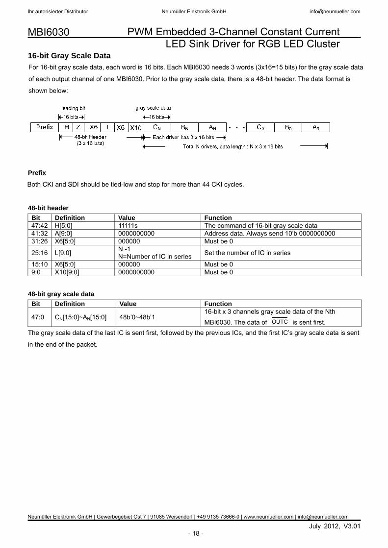
16-bit Gray Scale Data
For 16-bit gray scale data, each word is 16 bits. Each MBI6030 needs 3 words (3x16=15 bits) for the gray scale data
of each output channel of one MBI6030. Prior to the gray scale data, there is a 48-bit header. The data format is
shown below:
Prefix
Both CKI and SDI should be tied-low and stop for more than 44 CKI cycles.
48-bit header Bit Definition Value Function 47:42 H[5:0] 11111s The command of 16-bit gray scale data 41:32 A[9:0] 0000000000 Address data. Always send 10’b 0000000000 31:26 X6[5:0] 000000 Must be 0
25:16 L[9:0] N -1 N=Number of IC in series Set the number of IC in series
15:10 X6[5:0] 000000 Must be 0 9:0 X10[9:0] 0000000000 Must be 0
48-bit gray scale data Bit Definition Value Function
47:0 CN[15:0]~AN[15:0] 48b’0~48b’1 16-bit x 3 channels gray scale data of the Nth MBI6030. The data of OUTC is sent first.
The gray scale data of the last IC is sent first, followed by the previous ICs, and the first IC’s gray scale data is sent
in the end of the packet.
Ihr autorisierter Distributor Neumüller Elektronik GmbH [email protected]
Neumüller Elektronik GmbH | Gewerbegebiet Ost 7 | 91085 Weisendorf | +49 9135 73666-0 | www.neumueller.com | [email protected]

PWM Embedded 3-Channel Constant Current LED Sink Driver for RGB LED Cluster
July 2012, V3.01 - 19 -
MBI6030
10-bit Gray Scale Data For 10-bit gray scale data, each word is 10 bits. Each MBI6030 needs 3 words (3x10=30 bits) for the gray scale data
of each output channel of one MBI6030. Prior to the gray scale data, there is a 30-bit header. The data format is
shown below:
Prefix
Both CKI and SDI should be tied-low and stop for more than 44 CKI cycles.
30-bit header Bit Definition Value Function 29:24 H[5:0] 10101s The command of 10-bit gray scale data 23:20 X4[3:0] 0000 Must be 0 19:10 A[9:0] 0000000000 Address data. Always send 10’b 0000000000
9:0 L[9:0] N-1 N=Number of IC in series Set the number of IC in series
30-bit gray scale data Bit Definition Value Function
29:0 CN[9:0]~AN[9:0] 30b’0~30b’1 10-bit x 3 channels gray scale data of the Nth MBI6030. The data of OUTC is sent first.
The gray scale data of the last IC is sent first, followed by the previous ICs, and the first IC’s gray scale data is sent
in the end of the packet.
Embedded Voltage Regulator MBI6030 has an embedded voltage regulator to regulate the high input supply voltage to 5V supply voltage for
internal use. The input voltage is ranging from 7~30V, which is suitable for 12V/24V system. The high supply voltage
is connected to VDDH, and the output of the regulator is connected to CA. An external capacitor of 10uF should be
connected between CA and ground to stabilize the output voltage. Please refer to the application circuit section or
MBI6030 application note for further details on circuit design.
Ihr autorisierter Distributor Neumüller Elektronik GmbH [email protected]
Neumüller Elektronik GmbH | Gewerbegebiet Ost 7 | 91085 Weisendorf | +49 9135 73666-0 | www.neumueller.com | [email protected]

PWM Embedded 3-Channel Constant Current LED Sink Driver for RGB LED Cluster
July 2012, V3.01 - 20 -
MBI6030
Constant Current
1) MBI6030 performs excellent current skew: the maximum current variation between channels is less than ±3%,
and that between ICs is less than ±6%.
2) In addition, in the saturation region, the output current keeps constant when the output voltage (VDS) is changed. .
This characteristic guarantees the LED show the same brightness regardless of the variations of LED forward
voltages (VF)
Fig. 1 GCLK=9MHz
Fig. 2 GCLK=4.5MHz
0
20
40
60
80
100
120
140
160
0.0 0.5 1.0 1.5 2.0 2.5 3.0
VDS(V)
I OU
T(m
A)
MBI6030 IOUT vs. VDS
MBI6030 IOUT vs. VDS
0
20
40
60
80
100
120
140
160
0 0.5 1 1.5 2 2.5 3
VDS (V)
IOU
T (m
A)
Ihr autorisierter Distributor Neumüller Elektronik GmbH [email protected]
Neumüller Elektronik GmbH | Gewerbegebiet Ost 7 | 91085 Weisendorf | +49 9135 73666-0 | www.neumueller.com | [email protected]
PWM Embedded 3-Channel Constant Current LED Sink Driver for RGB LED Cluster
July 2012, V3.01 - 21 -
MBI6030
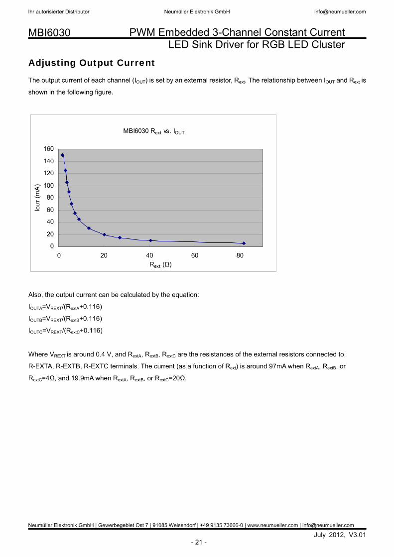
Adjusting Output Current
The output current of each channel (IOUT) is set by an external resistor, Rext. The relationship between IOUT and Rext is
shown in the following figure.
Also, the output current can be calculated by the equation:
IOUTA=VREXT/(RextA+0.116)
IOUTB=VREXT/(RextB+0.116)
IOUTC=VREXT/(RextC+0.116)
Where VREXT is around 0.4 V, and RextA, RextB, RextC are the resistances of the external resistors connected to
R-EXTA, R-EXTB, R-EXTC terminals. The current (as a function of Rext) is around 97mA when RextA, RextB, or
RextC=4Ω, and 19.9mA when RextA, RextB, or RextC=20Ω.
MBI6030 Rext vs. IOUT
0
20
40
60
80
100
120
140
160
0 20 40 60 80Rext (Ω)
IOU
T (m
A)
Ihr autorisierter Distributor Neumüller Elektronik GmbH [email protected]
Neumüller Elektronik GmbH | Gewerbegebiet Ost 7 | 91085 Weisendorf | +49 9135 73666-0 | www.neumueller.com | [email protected]

PWM Embedded 3-Channel Constant Current LED Sink Driver for RGB LED Cluster
July 2012, V3.01 - 22 -
MBI6030
Package Power Dissipation (PD)
The maximum power dissipation, PD(max)=(Tj,max–Ta)/Rth(j-a), decreases as the ambient temperature increases.
Please refer to the following figure to design within the safe operation area.
TP Function (Thermal Protection)
MBI6030 will automatically protect IC from overheating when the junction temperature exceeds the threshold, TX
(typ. 155oC). If the POL is pulled up, the output current will be turned off, but SDO and CKO is still work. Thus, the
junction temperature starts to decrease. When the temperature is decreased to TRECV (typ. 130oC), the output
current will be turned on again.
MBI6030 Maximum Power Dissipation at Various Ambient Temperature
0.0
0.5
1.0
1.5
2.0
2.5
3.0
3.5
4.0
0 10 20 30 40 50 60 70 80 90 100 Ambient Temperature (°C)
Power Dissipation (W)
GP Type: Rth=67.44°C/W
GFN Type: Rth=42.10°C/W
Safe Operation Area
Ihr autorisierter Distributor Neumüller Elektronik GmbH [email protected]
Neumüller Elektronik GmbH | Gewerbegebiet Ost 7 | 91085 Weisendorf | +49 9135 73666-0 | www.neumueller.com | [email protected]

PWM Embedded 3-Channel Constant Current LED Sink Driver for RGB LED Cluster
July 2012, V3.01 - 23 -
MBI6030
Load Supply Voltage (VLED)
The design of V LED should fulfill two targets:
1. Less power consumption and heat
2. Sufficiently headroom for the LED and driver IC to operate in the constant current region.
The power dissipation (PD) of MBI6030 is calculated by the equation:
PD=(VDDH x IDD) + [IOUTA x (VDSA –VREXTA)] + [IOUTB x (VDSB –VREXTB)] + [IOUTC x (VDSC –VREXTC)]
From the figure below, VDS = VLED – VF, which VLED is the supply voltage of LED. PD (act) will be greater than PD (max), if
VDS drops too much voltage on the driver. In this case, it is recommended to use the lowest possible supply voltage
or to set an external resistor to reduce the by VDROP.
VDS=(VLED–VF)–VDROP
Please refer to the following figure for the application of the resister.
Switching Noise Reduction
LED drivers are frequently used in switch-mode applications which always behave with switching noise due to the
parasitic inductance on PCB. To eliminate switching noise, please refer to “Application Note for 8-bit and 16-bit LED
Drivers-Overshoot”.
MBI6030
VF VDS
VDrop
Voltage Supply
VLED
Ihr autorisierter Distributor Neumüller Elektronik GmbH [email protected]
Neumüller Elektronik GmbH | Gewerbegebiet Ost 7 | 91085 Weisendorf | +49 9135 73666-0 | www.neumueller.com | [email protected]

PWM Embedded 3-Channel Constant Current LED Sink Driver for RGB LED Cluster
July 2012, V3.01 - 24 -
MBI6030
Soldering Process of “Pb-free” Package Plating*
Macroblock has defined "Pb-Free" to mean semiconductor products that are compatible with the current RoHS
requirements and selected 100% pure tin (Sn) to provide forward and backward compatibility with both the current
industry-standard SnPb-based soldering processes and higher-temperature Pb-free processes. Pure tin is widely
accepted by customers and suppliers of electronic devices in Europe, Asia and the US as the lead-free surface
finish of choice to replace tin-lead. Also, it is backward compatible to standard 215ºC to 240ºC reflow processes
which adopt tin/lead (SnPb) solder paste. However, in the whole Pb-free soldering processes and materials, 100%
pure tin (Sn) will all require from 245 oC to 260oC for proper soldering on boards, referring to JEDEC J-STD-020C as
shown below.
Package Thickness Volume mm3
<350 Volume mm3
350-2000 Volume mm3
≧2000
<1.6mm 260 +0 oC 260 +0 oC 260 +0 oC
1.6mm – 2.5mm 260 +0 oC 250 +0 oC 245 +0 oC ≧2.5mm 250 +0 oC 245 +0 oC 245 +0 oC
*Note: For details, please refer to Macroblock’s “Policy on Pb-free & Green Package”.
0 50 100 150 200 250 300
0
50
100
150
200
250
300
Temperature ()
Time (sec)
25
217
240
255
Average ramp-uprate= 3.3/s
Average ramp-uprate= 0.7/s
100s max
30s max
Ramp-down6/s (max)
Peak Temperature 245~260< 10s
----Maximum peak temperature Recommended reflow profile
260+0-5
245±5
Acc.J-STD-020C
Average ramp-uprate = 0.4/s
JEDEC J-STD-020C
Ihr autorisierter Distributor Neumüller Elektronik GmbH [email protected]
Neumüller Elektronik GmbH | Gewerbegebiet Ost 7 | 91085 Weisendorf | +49 9135 73666-0 | www.neumueller.com | [email protected]

PWM Embedded 3-Channel Constant Current LED Sink Driver for RGB LED Cluster
July 2012, V3.01 - 25 -
MBI6030
Package Outline
MBI6030GP Outline Drawing
Ihr autorisierter Distributor Neumüller Elektronik GmbH [email protected]
Neumüller Elektronik GmbH | Gewerbegebiet Ost 7 | 91085 Weisendorf | +49 9135 73666-0 | www.neumueller.com | [email protected]

PWM Embedded 3-Channel Constant Current LED Sink Driver for RGB LED Cluster
July 2012, V3.01 - 26 -
MBI6030
Remark: The thermal pad size may exist a tolerance due to the manufacturing process, please use the maximum
dimensions-D2(max.) x E2(max.) for the thermal pad layout. In addition, to avoid the short circuit risk, the vias or
circuit traces shall not pass through the maximum area of thermal pad.
Note: The unit of the outline drawing is millimeter (mm).
MBI6030 GFN Outline Drawing
9 10 0.5mm
Ihr autorisierter Distributor Neumüller Elektronik GmbH [email protected]
Neumüller Elektronik GmbH | Gewerbegebiet Ost 7 | 91085 Weisendorf | +49 9135 73666-0 | www.neumueller.com | [email protected]

PWM Embedded 3-Channel Constant Current LED Sink Driver for RGB LED Cluster
July 2012, V3.01 - 27 -
MBI6030
Product Top-mark Information
Product Revision History Datasheet version Device version code V1.00 A V1.01 A V2.00 B V3.00 B V3.01 B
Product Ordering Information Part Number RoHS Compliant
Package Type Weight (g)
MBI6030GP SSOP16L-150-0.64 0.111g MBI6030GFN QFN24L-4*4-0.5 0.038g
Part number
ID number XXXXXXXX
ManufactureCode Device Version Code
The second row of printing MBIXXXX
Product No. Package Code Process Code G: Green
The first row of printing
MBIXXXX Or
Ihr autorisierter Distributor Neumüller Elektronik GmbH [email protected]
Neumüller Elektronik GmbH | Gewerbegebiet Ost 7 | 91085 Weisendorf | +49 9135 73666-0 | www.neumueller.com | [email protected]

PWM Embedded 3-Channel Constant Current LED Sink Driver for RGB LED Cluster
July 2012, V3.01 - 28 -
MBI6030
Disclaimer
Macroblock reserves the right to make changes, corrections, modifications, and improvements to their products and
documents or discontinue any product or service. Customers are advised to consult their sales representative for
the latest product information before ordering. All products are sold subject to the terms and conditions supplied at
the time of order acknowledgement, including those pertaining to warranty, patent infringement, and limitation of
liability. Macroblock’s products are not designed to be used as components in device intended to support or sustain life or in
military applications. Use of Macroblock’s products in components intended for surgical implant into the body, or
other applications in which failure of Macroblock’s products could create a situation where personal death or injury
may occur, is not authorized without the express written approval of the Managing Director of Macroblock.
Macroblock will not be held liable for any damages or claims resulting from the use of its products in medical and
military applications. Related technologies applied to the product are protected by patents. All text, images, logos and information
contained on this document is the intellectual property of Macroblock. Unauthorized reproduction, duplication,
extraction, use or disclosure of the above mentioned intellectual property will be deemed as infringement.
Ihr autorisierter Distributor Neumüller Elektronik GmbH [email protected]
Neumüller Elektronik GmbH | Gewerbegebiet Ost 7 | 91085 Weisendorf | +49 9135 73666-0 | www.neumueller.com | [email protected]
Related Documents