GE Energy Connections Grid Solutions MBCI Translay S Technical Manual Differential Feeder and Transformer Feeder Protection Publication reference: R8011H

Welcome message from author
This document is posted to help you gain knowledge. Please leave a comment to let me know what you think about it! Share it to your friends and learn new things together.
Transcript
GE Energy Connections Grid Solutions
MBCI Translay S
Technical Manual Differential Feeder and Transformer Feeder Protection
Publication reference: R8011H

Page 2
CONTENTS
1. INSTALLATION 3
2 COMMISSIONING 4 2.1 Commissioning preliminaries 4 2.1.1 Electrostatic discharges (ESD) 4 2.1.2 Inspection 4 2.1.3 Wiring 4 2.1.4 Earthing 4 2.1.5 Insulation 4 2.2 Commissioning tests 4 2.2.1 General 4 2.2.2 Test equipment 5 2.2.3 Current setting tests 5 2.2.4 Timing tests 7 2.2.5 Primary injection tests 8 2.2.6 On load tests 9
3. MAINTENANCE 10 3.1 Removal of the relay from its case 10
4. PROBLEM ANALYSIS 10 4.1 Tests on ac circuits 11 4.2 DC power supply circuit 12 4.3 Output circuit 13 4.4 Printed circuit board 14 4.5 Recalibration and test 14
5 COMMISSIONING TEST RECORD 19

Page 3
Section 1. INSTALLATION
1.1
1.2
1.3
1.4
1.5
Protective relays, although generally of robust construction, require careful treatment prior to installation and a wise selection of site. By observing a few simple rules the possibility of premature failure is eliminated and a high degree of performance can be expected. The relays are either despatched individually or as part of a panel/rack mounted assembly, in cartons specifically designed to protect them from damage. Relays should be examined immediately they are received to ensure that no damage has been sustained in transit. If damage due to rough handling is evident, a claim should be made to the Transport Company concerned immediately, and the nearest General Electric branch office should be promptly notified. Relays which are supplied unmounted and not intended for immediate installation should be returned to their protective polythene bags. Care must be taken when unpacking and installing the relays so that none of the parts are damaged or their settings altered, and they must at all times be handled by skilled persons only. Relays should be examined for any wedges, clamps, or rubber bands necessary to secure moving parts to prevent damage during transit and these should be removed after installation and before commissioning. Relays which have been removed from their cases should not be left in situations where they are exposed to dust or damp. This particularly applies to installations which are being carried out at the same time as construction work. If relays are not installed upon receipt they should be stored in a place free from dust and moisture in their original cartons and where dehumidifier bags have been included in the packing they should be retained. The action of the dehumidifier crystals will be impaired if the bag has been exposed to ambient conditions and may be restored by gently heating the bag for about an hour, prior to replacing it in the carton. Dust which collects on a carton may, on subsequent unpacking, find its way into the relay; in damp conditions the carton and packing may become impregnated with moisture and the dehumidifying agent will lose its efficiency. Storage temperature –25°C to +70°C. The installation should be clean, dry and reasonably free from dust and excessive vibration. The site should preferably be well illuminated to facilitate inspection. An outline diagram is normally supplied showing panel cut-outs and hole centres. For individually mounted relays these dimensions will also be found in publication R6026. Publication R7012, Parts Catalogue and Assembly Instructions, will be useful when individual relays are to be assembled as a composite rack or panel mounted assembly.
Page 4
Section 2 COMMISSIONING
2.1 Commissioning preliminaries 2.1.1 Electrostatic discharges (ESD)
The relay has components which are sensitive to electrostatic discharges. When handling the module, care should be taken to avoid contact with components and electrical connections. When removed from the case for storage, the module should be placed in an electrically conducting anti-static bag.
2.1.2 Inspection Carefully examine the module and case to see that no damage has occurred during transit. Check that the serial number on the module, case and cover are identical and that the model number and rating information are correct. Carefully remove any elastic bands/packing fitted for transportation purposes.
2.1.3 Wiring Check that the external wiring is correct to the relevant relay diagram and scheme diagram. The relay diagram number appears inside the case. Particular attention should be paid to the correct wiring and value of any external resistors indicated on the wiring diagram/relay rating information. Note: The shorting switches shown on the relay diagram are fitted internally
across the relevant case terminals and close when the module is withdrawn. It is essential that such switches are fitted across all ct circuits.
If the test block type MMLG is provided, the connections should checked to the live side of the test block (coloured orange) and with terminals allocated with odd numbers (1,3,5,7, etc.). The auxiliary supply voltage to the scheme should be routed via test block terminals 13 and 15.
2.1.4 Earthing Ensure that the case earthing connection above the rear terminal block is used to connect the relay to a local earth bar.
2.1.5 Insulation The relay and its associated wiring may be insulation tested between: – all electrically isolated circuits. – all circuits and earth. An electronic or brushless insulation tester should be used, having a dc voltage not exceeding 1000V. Accessible terminals of the same circuit should first be strapped together. Deliberate circuit earthing links, removed for the tests must be replaced.
2.2 Commissioning tests 2.2.1 General
If the relay is wired through an MMLG test block, it is recommended that all secondary injection tests should be carried out using this block. Ensure that the main system current transformers are shorted before isolating the relay from the current transformers in preparation for secondary injection tests.

Page 5
DANGER DO NOT OPEN CIRCUIT THE SECONDARY CIRCUIT OF A CURRENT TRANSFORMER SINCE THE HIGH VOLTAGE PRODUCED MAY BE LETHAL AND COULD DAMAGE THE INSULATION. When the type MMLG test block facilities are installed, it is important that the sockets in the type MMLB01 test plug, which correspond to the current transformer secondary windings, are LINKED BEFORE THE TEST PLUG IS INSERTED INTO THE TEST BLOCK. Similarly, type MMLB02 single finger test plug must be terminated with an ammeter BEFORE IT IS INSERTED to monitor ct secondary currents. It is assumed that the initial preliminary checks have been carried out. There are several MIDOS Translay S schemes as shown in the MBCI publication R6011. The following commissioning procedure covers the MBCI relay and Translay S schemes. Commissioning instructions for other relays in the schemes are contained in the appropriate Service Manual.
MRTP Pilot supervision relay R8026 MCRI Instantaneous overcurrent relay R8028 MVTW Destabilising or destabilising
and intertrip relay R8027
The instructions have been written assuming that all Translay S schemes are not fitted with a test block at each end of the feeder. Where a test block has been fitted, the procedure is generally correct, but it will be necessary to find the correct test block terminals at which to inject current, supply dc and monitor for relay operation, from the relevant schematic diagram.
2.2.2 Test equipment Current injection test set suitable for secondary and primary injection. MMLB multi-way test plugs for MIDOS test block (when fitted). Two plugs, one for each line end, are required. Multi-range ammeter. Equipment to measure the resistance of the pilots. Short (8") leads with 4mm plug terminations: up to 26, ie.13 for each line end, may be required.
2.2.3 Current setting tests All Translay S schemes have an MBCI relay at each line end which provides the basic differential protection. To prove the calibration of the relay, it is convenient to check each end separately, isolated from the pilots. Single phase current is injected from a test set. a) If the scheme has overcurrent starter relays, there will be an MCRI relay. When
testing the MBCI differential relay, it is necessary to short the contact of the MCRI relay. This may be done across terminals 2 and 4 at the rear of the MCRI overcurrent relay.

Page 6
b) Before carrying out any current injection, set the relay as follows:- Rpp = 5 x 100 Ks = 1 Kt = 20 N = 3 The stabilising resistor Rs in the neutral from the cts should also be set. It is an adjustable resistance and must be set to: Rs = VKP/40In but not greater than 12/(In)2 Ohms where VKP = knee point voltage of line ct. In = rated secondary current.
c) Ensure that the normal dc supply is present and wired correctly to the relay, otherwise no relay operation or indication will occur when relay current injection is carried out
d) Inject the current from the test set into the relay for an A-N fault. Increase the current from zero until relay operation occurs and note this current. Relay operation will be indicated by operation of the trip indicator on the MBCI differential relay. It is advisable to check that all the alarm and trip circuit contacts operate by monitoring at the appropriate terminals on the rear of the case. As the relay is not connected to the pilots, it operates at approximately 0.5 times the nominal setting. Because the nominal setting for an A to N fault is 19% of rated relay current, the relay should operate at 0.5 x 0.19 x In ie. 95mA for a 1A rated relay and 474mA for a 5A rated relay. The operating current should be within 10% of the above current.
e) To check the other phases, change the injection supply from A - N to B - N and C - N. The settings should be 1.31 and 1.75 times the setting current measured for the A phase in (d).
f) The relay setting with N = 6 may be checked by injecting as in (d), the relay should operate at 0.64 times the setting current measured for the A phase.
g) To check the operation with the relay connected to the pilots, it is necessary to set the adjustable padding resistor (Rpp) at each relay end to the correct value, To do this the resistance of the pilot loop must be found. The pilot loop resistance may be measured either directly where the pilots enter the relay cubicle, or in many instances it can be measured from a test plug. NOTE: if there are external isolating transformers, care must be taken to
measure the total pilot resistance, not just the resistance of the first pilot isolating transformer.
If there are no external isolating transformers, measurement can be performed as detailed below: Measure the resistance of the pilot loop Rp. Set the adjustable padding resistor Rpp at both ends of the line to 0.5 x (1000 - Rp) where Rp = pilot resistance (Ohms).
Page 7
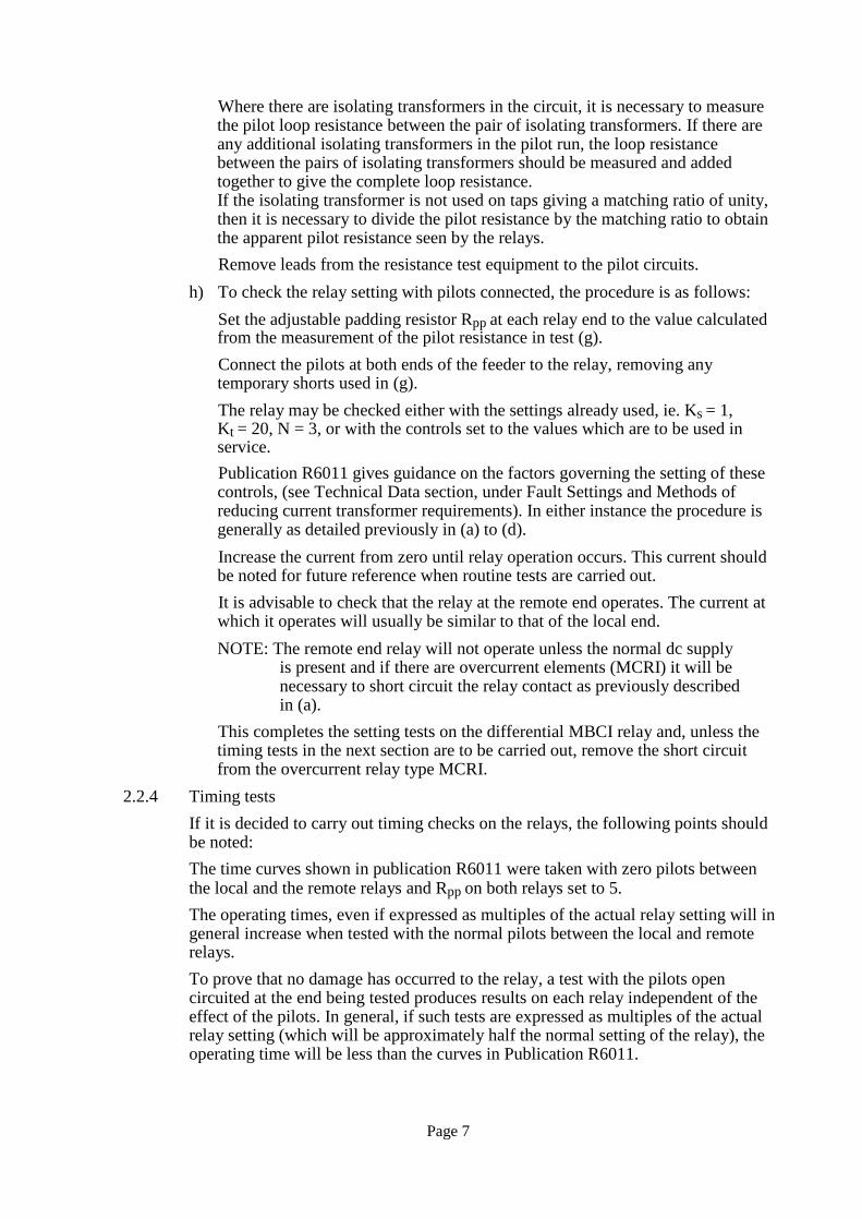
Where there are isolating transformers in the circuit, it is necessary to measure the pilot loop resistance between the pair of isolating transformers. If there are any additional isolating transformers in the pilot run, the loop resistance between the pairs of isolating transformers should be measured and added together to give the complete loop resistance. If the isolating transformer is not used on taps giving a matching ratio of unity, then it is necessary to divide the pilot resistance by the matching ratio to obtain the apparent pilot resistance seen by the relays. Remove leads from the resistance test equipment to the pilot circuits.
h) To check the relay setting with pilots connected, the procedure is as follows: Set the adjustable padding resistor Rpp at each relay end to the value calculated from the measurement of the pilot resistance in test (g). Connect the pilots at both ends of the feeder to the relay, removing any temporary shorts used in (g). The relay may be checked either with the settings already used, ie. Ks = 1, Kt = 20, N = 3, or with the controls set to the values which are to be used in service. Publication R6011 gives guidance on the factors governing the setting of these controls, (see Technical Data section, under Fault Settings and Methods of reducing current transformer requirements). In either instance the procedure is generally as detailed previously in (a) to (d). Increase the current from zero until relay operation occurs. This current should be noted for future reference when routine tests are carried out. It is advisable to check that the relay at the remote end operates. The current at which it operates will usually be similar to that of the local end. NOTE: The remote end relay will not operate unless the normal dc supply
is present and if there are overcurrent elements (MCRI) it will be necessary to short circuit the relay contact as previously described in (a).
This completes the setting tests on the differential MBCI relay and, unless the timing tests in the next section are to be carried out, remove the short circuit from the overcurrent relay type MCRI.
2.2.4 Timing tests If it is decided to carry out timing checks on the relays, the following points should be noted: The time curves shown in publication R6011 were taken with zero pilots between the local and the remote relays and Rpp on both relays set to 5. The operating times, even if expressed as multiples of the actual relay setting will in general increase when tested with the normal pilots between the local and remote relays. To prove that no damage has occurred to the relay, a test with the pilots open circuited at the end being tested produces results on each relay independent of the effect of the pilots. In general, if such tests are expressed as multiples of the actual relay setting (which will be approximately half the normal setting of the relay), the operating time will be less than the curves in Publication R6011.
Page 8
If the relay is tested with the normal pilots, Rpp must be set for the correct value and the actual settings measured. In general a test at 5 times these settings is a reasonable check. The times obtained are likely to exceed the time given in R6011. It may be decided to check the times on each Kt setting in turn. If this is done the main object is to check that as the Kt value is increased, the operating time at 5 times setting decreases. The set up procedure is the same as detailed in tests 2.2.3 (h), except that an additional two pole switch is wired as follows: One pole is used to apply the current from the injection test set and the second pole is used to start an interval timer. NOTE: If there is any doubt about the two poles of the switch closing at the same
time, it is advisable to measure the time difference. This is achieved by connecting one pole of the switch to the interval timer start and the other pole of the switch to the interval timer stop.
Connect the tripping contacts from the relay to stop the interval timer. a) With the pilots connected and the switch closed, increase the injected current
from zero until the local relay operates. Note the value of this current. b) Increase the current to 5 times the current measured in (a) and open the switch. c) Reset the timer, measure the operating time of the relay by closing the switch.
There will be a scatter of approximately 5ms in the time delays measured due to the point on wave at which the timer is started. It is therefore advisable to take the average of approximately ten readings. This average should be between 45 and 70 ms with Kt set to 20, but the actual time delay will be modified by pilot capacitance. If considered desirable, the timing may be carried out at other values of Kt. The average times at 5 times setting should be approximately the times in publication R6011 for short pilots (low capacitance) and exceed these values for longer pilots. No further tests are needed on the differential relay. Remove the short circuit from terminals 2 and 4 of the MCRI overcurrent relay.
d) All previous tests must be repeated on the relay at the remote end of the feeder. 2.2.5 Primary injection tests
The tests below use the setting of the differential unit with its summation transformer to identify the correct connection and ratio of the main current transformers. If there is an MCRI overcurrent relay, the contacts should be shorted by connecting across terminals 2 and 4 on the rear terminal block of the MCRI relay.G10 a) Inject current into the A phase ct at one end of the feeder and check that the
relays at the local and remote ends operate at approximately the correct settings. This should be determined by multiplying the results of tests carried out in 2.2.3 (h) by the ct ratio.
b) Repeat test (a) above but injecting into the B phase ct. The setting should have increased in the ratio 5.25/4 for N = 3 (or 8.25/7 for N = 6).
c) Repeat test (a) above but injecting into the C phase ct. The setting should have increased in the ratio 5.25/3 for N = 3 (or 8.25/6 for N = 6).
Page 9
d) Inject current into the A phase and B phase cts by injecting on the bus side and connecting A and B phases on the line side of the cts. Thus an A to B phase fault is simulated and the current setting may be checked. If N = 3, the setting should be approximately 5.25/1.25 times the result of (a). If it is much lower than expected, it is probably because one of the cts is connected in reverse.
e) Repeat test (d) above using the B and C phase cts. If N = 3 the setting should be approximately 5.25 times the result of (a).
f) Tests (a) to (e) should be repeated at the other end of the feeder to check the relative ct polarities and phase connections at that end.
2.2.6 On load tests These tests are to check the relative polarity and phasing of the line cts at each end of the protected feeder. For the tests below it is essential to obtain three phase current down the feeder and through the cts. The current need not be as high as three phase full load current and the amount necessary will vary depending on the relay current setting. If the relays at both ends are set with the minimum setting, ie. N = 6 and Ks = 0.5 for this test, then a through three phase current of 20% of the rated current should always prove to be sufficient to prove the relative polarity and phasing of the main cts. A current of 10% is adequate to check the relative polarity only. If the scheme has overcurrent starter ie. an MCRI relay, the three phase through load will either need to be in excess of the phase fault starter setting, which may be down to 40% of the relay rated current, or the contact from the MCRI must be shorted (see 2.2.6 (b)). The A - N setting must always be kept above the line charging current. Test as follows: a) With the circuit breakers open at each end of the protected feeder, short circuit
the B and C phase main cts to neutral and isolate them from the relays at each end of the feeder, as shown in Figure 1, leaving only the A phase main ct connected to the relay.
b) If the scheme has overcurrent starter relays ensure that either the through load will operate a phase fault starter, or short the contact from the MCRI relay. This may be done across terminals 2 and 4 at the rear of the MCRI overcurrent relay and must be done at both ends of the protected feeder.
c) Close the circuit breakers at both ends of the feeder and apply a through load greater than 20% of the relay rated current. Check for relay operation. If there is no relay operation it may indicate that the relative polarity of the line cts is correct. However, it is necessary to check this by reversing the polarity of the pilots. This should produce operation. Relay operation should occur, indicating that the original ct connection was correct. If with the original pilot connection the relays operate, it may indicate that either the pilots are reversed or the cts have been connected to give the wrong polarity at one feeder end. To confirm this, reverse the pilots as above and show that the relays do not operate. NOTE: If the scheme includes the supervision relay MRTP, the possibility of
crossed pilots can be eliminated by commissioning this relay, thus leaving only cts incorrectly connected to give the wrong polarity.

Page 10
In the unlikely event of there being incorrect phasing between feeder ends, there will be operation of one or both relays. Reversing the pilots will still cause operation.
d) Since test (c) only used A phase current, it will not check for incorrect phasing on B or C phases. To check for this possibility remove the through load and modify the ct wiring at both ends of the feeder to use the incoming B phase current. Short circuit the incoming A and C phase main cts to neutral and isolate them from the relay. Connect the B phase and neutral main ct to the relay. Apply a through load greater than 20% rated current and as described previously there should be no relay operation. Test (c) eliminated the possibility of crossed pilots, or cts connected to give the wrong polarity. Therefore, if the relays operate, it must be the B and C primary lines crossed between ends. To correct this may be difficult and the engineer may decide to remedy the cross-over by crossing the ct connections to the relay at one end. The through load should be re-applied to check that there is no relay operation after any change to the system. Switch off the through load and set the Rpp, Ks and N controls to the required setting. Restore the main ct connections back to normal at both ends of the protected feeder. Remove any short circuits that may have been applied across terminals 2 and 4 of the overcurrent relay MCRI (where applicable).
Section 3. MAINTENANCE
Periodic maintenance is not necessary. However, periodic inspection and test is recommended. Routine testing of the relay can be performed by the secondary method as detailed in the commissioning instructions. During testing the trip indicator should be checked for correct operation. Operation of the trip indicator should coincide with operation of the relay contacts. Check the trip indicator may be reset by pushing the reset push button.
3.1 Removal of the relay from its case To remove the relay from its case, loosen the cover nuts and remove the cover. The relay may now be lifted out of the case by pulling on the handles.
Section 4. PROBLEM ANALYSIS
Since the functioning of the differential circuit depends on there being a relay at each end of the protected line connected together by pilot lines, it is to be expected that a failure in the pilot circuit will produce a mal-operation at each end. This failure could be in the pilot wires or the pilot circuit within either relay. An open circuit or increased resistance in the pilot circuit will cause differential relays to operate at a current lower than expected and a short circuit or reduced resistance between pilot wires will cause the relays to operate higher than expected.
Page 11
NOTE: the supervision relay MRTP will give an alarm in the event of a pilot failure, but will not prevent a mal-operation caused by the failure.
If the mal-operation occurs in one differential relay, while the one at the other end of the line continues to operate satisfactorily, the fault is probably in the measuring or output circuits of the mal-operating relay. It is recommended that printed circuit boards (pcb) be replaced as a whole and that no attempt should be made to remove and replace components on a pcb. This preserves the integrity of the varnish coat on the pcb and prevents any difficulty in breaking through the varnish for soldering and subsequently repairing the varnish. To this end the fault finding instructions do not go into detail for finding faults on printed circuit boards. If it becomes necessary to return a relay for repair, a full description of any fault found should accompany the relay. This will assist our repair department to located and rectify the fault, and may save unnecessary correspondence and time if the fault is not immediately apparent. When ordering spare parts, the serial number and full model number of the relay should be included with the order.
4.1 Tests on ac circuits See flow charts Figures 2 and 3.
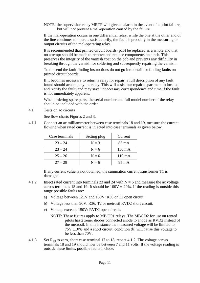
4.1.1 Connect an ac milliammeter between case terminals 18 and 19, measure the current flowing when rated current is injected into case terminals as given below.
Case terminals Setting plug Current 23 – 24 N = 3 83 mA 23 – 24 N = 6 130 mA 25 – 26 N = 6 110 mA 27 – 28 N = 6 95 mA
If any current value is not obtained, the summation current transformer T1 is damaged.
4.1.2 Inject rated current into terminals 23 and 24 with N = 6 and measure the ac voltage across terminals 18 and 19. It should be 100V ± 20%. If the reading is outside this range possible faults are: a) Voltage between 121V and 150V: R36 or T2 open circuit. b) Voltage less than 90V: R36, T2 or metrosil RVD2 short circuit. c) Voltage exceeds 150V: RVD2 open circuit.
NOTE: These figures apply to MBCI01 relays. The MBCI02 for use on rented pilots has 2 zener diodes connected anode to anode as RVD2 instead of the metrosil. In this instance the measured voltage will be limited to 75V ±10% and a short circuit, condition (b) will cause this voltage to be less than 70V.
4.1.3 Set Rpp to zero, short case terminal 17 to 18, repeat 4.1.2. The voltage across terminals 18 and 19 should now be between 7 and 11 volts. If the voltage reading is outside these limits, possible faults include:
Page 12
a) Voltage unchanged from 4.1.2: T2, RV1, R36, RECT1 or pilot connection open circuit. NOTE: RECT1 is encapsulated in a plastic box, this is to ensure the 5kV
isolation of the pilot circuit is achieved. b) Voltage reduced from 4.1.2 but greater than 11V: RECT1 partially open circuit,
or the knob of RV1 has been moved on the potentiometer shaft. c) Voltage less than 7 volts: RECT1 or T2 short circuit.
4.1.4 Increase the setting of Rpp to 5. The voltage across terminals 18 and 19 should rise to between 30 and 55V. If the voltage is outside these limits RV1 is damaged.
4.1.5 Disconnect the wires from one side of the metrosil RVD2, but leave all 3 wires connected together. Repeat tests 4.1.2., the voltage should now exceed 150V.
4.1.6 Check RV1: connect an resistance meter across the two outer tags on RV1 and measure the resistance at each calibrated position on the scale. The resistance should be the setting resistance ± 10%. The zero setting should be less than 10 Ohms.
4.1.7 Set Rpp = 5.0, Ks = 1.0, N = 3, Kt = 20. Apply rated ac current to case terminals 23 and 24, measure the voltage across R36 on PCB ZJ0041. The measured voltage should be 75V ac.
4.1.8. With rated ac current applied and Rpp set to zero, measure the voltage across Rpp (RV1). The measured voltage should be less than 0.75V.
4.1.9 Set Rpp = 5.0, Ks = 1.0, N = 3, Kt = 20. Remove the short on terminals 17 and 18. With rated ac applied measure the voltage on test points TP6 and TP11. The measured voltage should be 6.3V ac.
4.1.10 With rated ac current applied measure the voltage on test points TP4 and TP6. The measured voltage should be 2V ac.
4.1.11 Short together case terminals 17 and 18 and repeat test 4.1.10. The measured voltage should now be 0.35V - 0.5V. Set Rpp to zero. The voltage should change to 1.4V - 1.6V. NOTE: For tests 4.1.10 and 4.1.11 a high impedance ac voltmeter must be used.
4.1.12 If a voltage is obtained in test 4.1.10, change the Ks setting to infinity. The voltage should fall to zero, if the voltage does not change RV2 is faulty.
4.1.13 To test RV2, disconnect a wire from one side of the potentiometer and measure the resistance. The measured value should range from zero to 2k as the potentiometer is turned.
4.2 DC power supply circuit The power supply circuit consists of a series regulating transistor TR6, which drops the incoming voltage to 15V nominal for the electronic measuring circuit. This voltage, measured on test points TP1 and TP7 should be between 14 and 16.5 volts with nominal dc voltage on case terminals 13 (+ve) and 14. This voltage is controlled by zener diode D17. The voltage across D17 measured on test points TP17 and TP7 should be between 15V and 17V.
Page 13
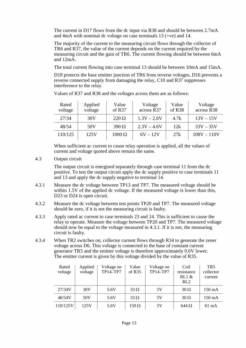
The current in D17 flows from the dc input via R38 and should be between 2.7mA and 4mA with nominal dc voltage on case terminals 13 (+ve) and 14. The majority of the current to the measuring circuit flows through the collector of TR6 and R37, the value of the current depends on the current required by the measuring circuit and the gain of TR6. The current flowing should be between 6mA and 12mA. The total current flowing into case terminal 13 should be between 10mA and 15mA. D18 protects the base emitter junction of TR6 from reverse voltages, D16 prevents a reverse connected supply from damaging the relay, C10 and R37 suppresses interference to the relay. Values of R37 and R38 and the voltages across them are as follows:
Rated
voltage Applied voltage
Value of R37
Voltage across R37
Value of R38
Voltage across R38
27/34 30V 220 Ω 1.3V – 2.6V 4.7k 13V – 15V
48/54 50V 390 Ω 2.3V – 4.6V 12k 33V – 35V 110/125 125V 1000 Ω 6V – 12V 27k 108V – 110V
When sufficient ac current to cause relay operation is applied, all the values of current and voltage quoted above remain the same.
4.3 Output circuit The output circuit is energised separately through case terminal 11 from the dc positive. To test the output circuit apply the dc supply positive to case terminals 11 and 13 and apply the dc supply negative to terminal 14.
4.3.1 Measure the dc voltage between TP13 and TP7. The measured voltage should be within 1.5V of the applied dc voltage. If the measured voltage is lower than this, D23 or D24 is open circuit.
4.3.2 Measure the dc voltage between test points TP20 and TP7. The measured voltage should be zero, if it is not the measuring circuit is faulty.
4.3.3 Apply rated ac current to case terminals 23 and 24. This is sufficient to cause the relay to operate. Measure the voltage between TP20 and TP7. The measured voltage should now be equal to the voltage measured in 4.3.1. If it is not, the measuring circuit is faulty.
4.3.4 When TR2 switches on, collector current flows through R34 to generate the zener voltage across D6. This voltage is connected to the base of constant current generator TR5 and the emitter voltage is therefore approximately 0.6V lower. The emitter current is given by this voltage divided by the value of R35.
Rated
voltage Applied voltage
Voltage on TP14–TP7
Value of R35
Voltage on TP14–TP7
Coil resistance
RL1 & RL2
TR5 collector current
27/34V 30V 5.6V 33 Ω 5V 30 Ω 150 mA
48/54V 50V 5.6V 33 Ω 5V 30 Ω 150 mA
110/125V 125V 5.6V 150 Ω 5V 644 Ω 61 mA

Page 14
RVD1 is a voltage dependant resistor which will prevent damage to the circuit due to high voltage impulses on the dc auxiliary supply.
4.4 Printed circuit board If, after following the above procedure, the fault has not been located, it must be on the printed circuit board. In this instance the relay should be returned to General Electric in Stafford or the nearest service centre for repair.
4.5 Recalibration and test
If the Rpp or Ks setting potentiometers are replaced they must be recalibrated as follows: a) Turn shaft of Ks potentiometer fully anti-clockwise. Align the marker on the
setting knob to the infinity position on the nameplate. b) Connect a digital resistance meter across the Rpp potentiometer. Turn the
potentiometer shaft until the reading is 100 Ohms. Align the setting dial mark with 1.0 on the nameplate. Check the values of Rpp are as follows. If any position is out of tolerance the dial may be rotated to give a position where all values are within the tolerance limits.
Rpp setting Nominal resistance
ohms
Tolerance limits ohms
5.0 500 450 – 550 4.0 400 360 – 440 3.0 300 270 – 330 2.0 200 180 – 220 1.0 100 90 – 110
0 0 0 – 15
All other calibrations are performed on the printed circuit board. Therefore replacement of other components should not alter the calibration. The relay should be recommissioned as described in Section 2 after the replacement of any components.

End A End B
A
B
C
A A
B B
C C
N N
Figure 1 End to end stability test using load current
Page 15

Page 16
Start
Perform Test 4.1.1
T1 faulty
Yes Any current wrong
No
Perform Test 4.1.2
Perform Test 4.1.3
Correct Voltage value
Low Perform Test 4.1.5
Perform
Test 4.1.4
High
Exceeds 150V
Yes Voltage No
correct
Perform Test 4.1.8
Low Voltage value
High Perform Test 4.1.8
RVDI faulty
R36 faulty
Correct
A
Perform
Test 4.1.7
Either
voltage low
Yes RVD2 faulty
Yes Either voltage low
Voltage
low
Yes T2 faulty
No No No
T2 faulty
Perform Test 4.1.9
R36 faulty
T2
faulty
Voltage
RV1 faulty
Current
Figure 2 MBCI fault finding flow chart

Page 17
A
No Voltage
correct
Yes
No Voltage
correct
Yes
Yes Both voltages correct
No
Yes RV1
faulty
No
Figure 3 MBCI fault finding flow chart
Perform Test 4.1.10
Perform Test 4.1.11
Perform Test 4.1.12
Perform Test 4.1.6
T2 or RV2 faulty
T1 faulty
T2 or RV2 faulty
AC circuits Healthy
Replace RV1
RL3
1 R
Protected zone
A P1 P2
B S1 S2 C
See Note 5
Protected zone
P2 P1 S2 S1
See Note 4
Rs
MCBI
12 13
MCBI Rs
23 IA
24 & 25
IB Squarer Kt
Enable
14
11
1 RL1–1 3
Vx
See 23
Note 2 IA
24 26 27 Enable
25 5 IB
A IC IN 28
C B N
Level
detector
2
RL1–2 4 6
26 27
Trip/ IC
Phase rotation 3 alarm OP output
& 7 28 IN
Case earth 1 2 3 4 5 6 7 8
6
Case earth See Note 3
KS O
Squarer RES RL2–1
RL2–2
9
8
10
9 10 11 12 13 14
15 16 17 18
19 20
21 22
Notes:
Rpp 17 17
18 Pilot wires 18 19
23 24
25 26
27 28
Module terminal block viewed from rear
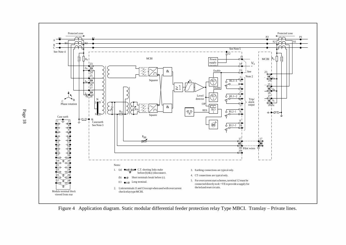
1. (a) C.T. shorting links make before (b) & (c) disconnect.
(b) Short terminals break before (c). (c) Long terminal.
2. Link terminals 11 and 13 except when used with overcurrent
check relay type MCRI.
3. Earthing connections are typical only.
4. CT connections are typical only.
5. For overcurrent start schemes, terminal 12 must be connected directly to dc +VE to provide a supply for the led and reset circuits.
Figure 4 Application diagram. Static modular differential feeder protection relay Type MBCI. Translay – Private lines.
Power supply circuits
RL1 2
RL2 2
Page 18
Page 19
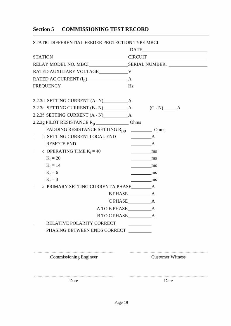
Section 5 COMMISSIONING TEST RECORD
STATIC DIFFERENTIAL FEEDER PROTECTION TYPE MBCI DATE
STATION CIRCUIT RELAY MODEL NO. MBCI SERIAL NUMBER. RATED AUXILIARY VOLTAGE V RATED AC CURRENT (In) A FREQUENCY Hz
2.2.3d SETTING CURRENT (A - N) A 2.2.3e SETTING CURRENT (B - N) A (C - N) A 2.2.3f SETTING CURRENT (A - N) A 2.2.3g PILOT RESISTANCE Rp
PADDING RESISTANCE SETTING Rpp Ohms
Ohms 2.2.3 h SETTING CURRENT LOCAL END A
REMOTE END A 2.2.4 c OPERATING TIME Kt = 40 ms
Kt = 20 ms Kt = 14 ms Kt = 6 ms Kt = 3 ms
2.2.5 a PRIMARY SETTING CURRENT A PHASE A B PHASE A C PHASE A
A TO B PHASE A B TO C PHASE A
2.2.6 RELATIVE POLARITY CORRECT PHASING BETWEEN ENDS CORRECT
..................................................................... .................................................................... Commissioning Engineer Customer Witness
..................................................................... .................................................................... Date Date

Page 20

Imagination at work
Grid Solutions St Leonards Building Redhill Business Park Stafford, ST16 1WT, UK +44 (0) 1785 250 070 www.gegridsolutions.com/contact
© 2017 General Electric. All rights reserved. Information contained in this document is indicative only. No representation or warranty is given or should be relied on that it is complete or correct or will apply to any particular project. This will depend on the technical and commercial circumstances. It is provided without liability and is subject to change without notice. Reproduction, use or disclosure to third parties, without express written authority, is strictly prohibited.
R8011H
Related Documents


