Maxum II PD PA AP Maxum II Reference Manual Manual Product Descriptions and Maintenance for Maxum II Airless/Airbath Model Gas Chormatograph 7/2017 2000596-001 Analyzer Overview 1 Electronic Compartment Component Descriptions and Maintenance Procedures 2 Specifications 3

Welcome message from author
This document is posted to help you gain knowledge. Please leave a comment to let me know what you think about it! Share it to your friends and learn new things together.
Transcript
Maxum II
PD PA APMaxum II Reference Manual
Manual
Product Descriptions and Maintenance for Maxum II Airless/Airbath Model Gas Chormatograph
7/20172000596-001
Analyzer Overview 1Electronic Compartment Component Descriptions and Maintenance Procedures
2
Specifications 3

Legal informationWarning notice system
This manual contains notices you have to observe in order to ensure your personal safety, as well as to prevent damage to property. The notices referring to your personal safety are highlighted in the manual by a safety alert symbol, notices referring only to property damage have no safety alert symbol. These notices shown below are graded according to the degree of danger.
DANGERindicates that death or severe personal injury will result if proper precautions are not taken.
WARNINGindicates that death or severe personal injury may result if proper precautions are not taken.
CAUTIONindicates that minor personal injury can result if proper precautions are not taken.
NOTICEindicates that property damage can result if proper precautions are not taken.If more than one degree of danger is present, the warning notice representing the highest degree of danger will be used. A notice warning of injury to persons with a safety alert symbol may also include a warning relating to property damage.
Qualified PersonnelThe product/system described in this documentation may be operated only by personnel qualified for the specific task in accordance with the relevant documentation, in particular its warning notices and safety instructions. Qualified personnel are those who, based on their training and experience, are capable of identifying risks and avoiding potential hazards when working with these products/systems.
Proper use of Siemens productsNote the following:
WARNINGSiemens products may only be used for the applications described in the catalog and in the relevant technical documentation. If products and components from other manufacturers are used, these must be recommended or approved by Siemens. Proper transport, storage, installation, assembly, commissioning, operation and maintenance are required to ensure that the products operate safely and without any problems. The permissible ambient conditions must be complied with. The information in the relevant documentation must be observed.
TrademarksAll names identified by ® are registered trademarks of Siemens AG. The remaining trademarks in this publication may be trademarks whose use by third parties for their own purposes could violate the rights of the owner.
Disclaimer of LiabilityWe have reviewed the contents of this publication to ensure consistency with the hardware and software described. Since variance cannot be precluded entirely, we cannot guarantee full consistency. However, the information in this publication is reviewed regularly and any necessary corrections are included in subsequent editions.
Siemens AGDivision Process Industries and DrivesPostfach 48 4890026 NÜRNBERGGERMANY
Document order number: 2000596-001 08/2017 Subject to change
Copyright © Siemens AG 2007 - 2017.All rights reserved

Table of contents
1 Analyzer Overview........................................................................................................................................7
1.1 Introduction..............................................................................................................................7
1.2 Analyzer Specific Documents..................................................................................................8
1.3 Parts of the Maxum II...............................................................................................................8
1.4 Isothermal Oven.......................................................................................................................9
1.5 Switching and Sampling Valves.............................................................................................10
1.6 Operator Controls...................................................................................................................11
2 Electronic Compartment Component Descriptions and Maintenance Procedures.....................................13
2.1 Power Supplies......................................................................................................................132.1.1 Power System Module...........................................................................................................132.1.2 Replacement Procedure........................................................................................................15
2.2 Power Entry and Control Module...........................................................................................182.2.1 PECM Overview.....................................................................................................................182.2.2 Feature Additions...................................................................................................................192.2.3 PECM Functions....................................................................................................................202.2.3.1 AC Input and Distribution.......................................................................................................202.2.3.2 Oven Temperature Control....................................................................................................212.2.3.3 Communication and Power Distribution.................................................................................222.2.3.4 Onboard Solid State Relays...................................................................................................232.2.3.5 Oven Functions......................................................................................................................242.2.3.6 Electronic Enclosure Environment.........................................................................................262.2.4 Replacement Procedure........................................................................................................282.2.4.1 Troubleshooting.....................................................................................................................282.2.4.2 Removing The PECM............................................................................................................302.2.4.3 Installing The New PECM......................................................................................................31
2.3 System Controller Version 2.1 (SYSCON2.1)........................................................................322.3.1 Description.............................................................................................................................322.3.2 Mechanical.............................................................................................................................332.3.3 SYSCON2.1 Components......................................................................................................342.3.3.1 Communication and Control Board (CAC3)...........................................................................342.3.3.2 CAC3 Status Indicator LEDs..................................................................................................352.3.3.3 SIB.........................................................................................................................................362.3.3.4 Ethernet Port Expansion........................................................................................................442.3.4 Maintenance Overview...........................................................................................................482.3.5 Service Procedures................................................................................................................482.3.6 Replacing the Lithium Battery on the SYSCON Module Introduction....................................532.3.7 Procedure...............................................................................................................................53
2.4 Analog and Digital IO.............................................................................................................542.4.1 IO Card Common Features....................................................................................................552.4.2 Digital IO Card........................................................................................................................582.4.3 Analog IO Board.....................................................................................................................59
Maxum II Reference ManualManual, 7/2017, 2000596-001 3

2.4.4 Analog and Digital IO Board...................................................................................................60
2.5 Detector Personality Modules................................................................................................612.5.1 DPM Types............................................................................................................................612.5.2 Base3 Detector Personality Module (DPM)...........................................................................612.5.3 Replacing a Base3DPM.........................................................................................................662.5.4 Intrinsically-Safe Thermal Conductivity DPM (IS-TCD3)........................................................682.5.5 Replacing an IS-TCD DPM....................................................................................................702.5.6 Replacing a TC-DPM.............................................................................................................71
2.6 Sensor Near Electronics (SNE) Software..............................................................................72
2.7 Solid State Relay Module.......................................................................................................74
2.8 Solenoid Valves.....................................................................................................................762.8.1 Solenoid Valve Control Module (SVCM)................................................................................762.8.2 Replacing a Solenoid Valve...................................................................................................80
2.9 Electronic Pressure Control Module.......................................................................................812.9.1 EPC Module Description........................................................................................................812.9.2 Replacing an EPC Module.....................................................................................................83
2.10 Color Touchscreen.................................................................................................................852.10.1 Description.............................................................................................................................852.10.2 Maintenance Overview...........................................................................................................852.10.3 Replacement Procedures.......................................................................................................86
3 Specifications.............................................................................................................................................93
Index...........................................................................................................................................................99
Table of contents
Maxum II Reference Manual4 Manual, 7/2017, 2000596-001

WARNING
Do not connect analyzer to the internet.
This equipment must not be connected to the internet except by a secure connection using a network security appliance administered by qualified IT personnel.
Failure to implement robust network security may expose your company to internet hacking attacks that could result in theft or loss of sensitive data, equipment damage, serious injury or death.
Maxum II Reference ManualManual, 7/2017, 2000596-001 5

Maxum II Reference Manual6 Manual, 7/2017, 2000596-001

Analyzer Overview 11.1 Introduction
The Maxum edition II system, also called the “Maxum II”, represents a significant advance in process chromatography. The Maxum II combines the best of the Siemens Advance Maxum and PGC 302 gas chromatographs into a single platform analyzer. From oven and electronic components to software and communication networks, the system is modular. Pre-configured application modules are available for many common measurements.
A Maxum II system offers a wide range of detector modules including Thermal Conductivity, Flame Ionization, Flame Photometric, and the Pulsed Discharge Detector (which can operate in Helium Ionization, Photoionization, and Electron Capture modes). All detector modules are available for both air bath and airless ovens. The Maxum II oven is designed so it can be divided into two independently heated isothermal ovens for parallel chromatography applications.
The Maxum II Maintenance Panel provides maintenance personnel with access to all maintenance functions and data. In addition, the Maintenance Panel displays both real time and archived chromatograms. A PC-based network workstation runs the Gas Chromatograph Portal software.
Analyzer Specific DocumentsIncluded with each analyzer is a custom documentation-drawing package. This package provides drawings and information pertinent only to a specific analyzer. Contents of this package are application-dependent and vary for each analyzer. Typical drawings included are:
System Block and Utility Requirements System Outline and Dimensional Drawings Sampling System - Plumbing and Spare
Parts List Sampling System Dimensional Diagram Sampling Probe Electronic Enclosure Section - Internal
Layout
Applicable Wiring Diagrams Oven Plumbing Diagram - Sensor Near
Electronics Recommended Spare Parts - Analyzer Manufacturing Test Charts Stream Composition Data Database
Maxum II Reference ManualManual, 7/2017, 2000596-001 7

1.2 Analyzer Specific DocumentsIncluded with each analyzer is a custom documentation-drawing package. This package provides drawings and information pertinent only to a specific analyzer. Contents of this package are application-dependent and vary for each analyzer. Typical drawings included are:
System Block and Utility Requirements System Outline and Dimensional Drawings Sampling System - Plumbing and Spare
Parts List Sampling System Dimensional Diagram Sampling Probe Electronics Compartment - Internal Layout
Applicable Wiring Diagrams Oven Plumbing Diagram - Sensor Near
Electronics Recommended Spare Parts - Analyzer Manufacturing Test Charts Stream Composition Data Database
1.3 Parts of the Maxum II
OverviewThe Maxum II Gas Chromatagraph is completely enclosed in an air-purgable, metal cabinet with hinged doors. Mounted above the isothermal oven is the electronics enclosure and regulator panel. The analyzer may be mounted on a wall, in a rack or on a floor stand.
Detector
Compartment
Regulator
Panel
Isothermal
Oven
Electronics
Enclosure
Color
Touchscreen
Figure 1-1 Maxum II External Component Locations
Analyzer Overview1.3 Parts of the Maxum II
Maxum II Reference Manual8 Manual, 7/2017, 2000596-001

Electronics EnclosureThe Electronics Enclosure houses all the electronics and pneumatic modules required for performing all temperature, valve control and analysis functions. The Electronics Enclosure modules are interconnected using simple cable connections made to each module. All modules can be easily removed and replaced. The Maxum II software recognizes each Maxum II’s application, hardware components and network configurations.
International
Power Supply
Solid
State
Relay
Module
Power
Entry
Control
Module
(PECM)
Detector Personality Module (DPM)
for Detector Data Acquisition
8-Channel Electronic
Pressure Control. Up
To 4 Modules. 2
Channels Each For
Control Of Carrier
Gas Pressure
System Controller (SYSCON) For Communications,
Human Interface and Database Management.
Figure 1-2 Electronics Enclosure Component Locations
Regulator PanelThe regulator panel contains space for seven gauges and regulators. The base Maxum II comes with two standard regulators and an electronics enclosure fast purge. See the custom documentation drawing package that was shipped with the analyzer to see which gauges and regulators are mounted on the analyzer.
1.4 Isothermal Oven
The Maxum ll has a wide variety of isothermal oven configurations. Both air bath and airless ovens are available. All air bath configurations are available with Vortex cooling for sub-ambient temperature operation. A program temperature oven option is available for Maxum II applications where isothermal, multi-dimensional chromatography is not practical. Typically the program temperature Maxum II is used for Motor Gasoline (ASTM 3710) & Simulated Distillation (ASTM 2887) applications.
Analyzer Overview1.4 Isothermal Oven
Maxum II Reference ManualManual, 7/2017, 2000596-001 9

Oven Configurations
Split Airless Oven
Fully independent dual ovens with separate oven doors. The oven uses cartridge heaters in each side to heat the oven enclosure and its components.
Single Air Bath Oven
Large, spacious compartment for complex applications and for ease of maintenance.
Programmed Temperature Air Bath Oven
Provides a programmed temperature gradient for applica‐tions requiring this.
Dual Air Bath Split Oven
Split Oven Configuration: Offers two temperature zones for one or more applications.
1.5 Switching and Sampling Valves
Application Model DescriptionVapor Samples Model 50 10-port non-plunger diaphragm. Contains no moving parts. It will operate over 10
million cycles on clean samples and can operate on carrier gas or other bottled inert gas with negligible consumption. It does the work of two Model 11 valves and is half the size.
Vapor or Liquid Sam‐ples
Model 11 and Model 11 LDV
6-port diaphragm–plunger valve high reliability and life. Used as a liquid or vapor sample valve, column switching valve or a column back flush valve. Process lines, columns and valve-to-valve tubes can be connected directly to the caps of the Model 11 LDV (Low Dead Volume) version of the valve.
Analyzer Overview1.5 Switching and Sampling Valves
Maxum II Reference Manual10 Manual, 7/2017, 2000596-001

Vapor or High Pres‐sure Liquid Samples
Model 20 The air-pressure actuated, diaphragm valve provides uniform sample volume, low internal volume, high pressure up to 1500 psi, 10350 kPa, fast switching (millisec‐onds), reliability, and durability. It functions equally well as a liquid or vapor sample valve, column switching valve, or column back flush valve.
Liquid Sample LIV The liquid injection valve can be used to automatically inject a constant quantity of liquid sample followed by fast, complete vaporization. Small gas quantities can also be injected using the valve.
Vapor Valveless Live Column Switching
The device has no parts to fail or wear out and exhibits essentially zero dead volume for fast column switching and sample injection with capillary columns.
1.6 Operator Controls
Color Touchscreen
The color touchscreen displays all mainte‐nance functions and data in a graphical dis‐play. In addition it can also display both real-time and stored chromatograms. The stored chromatograms include voltages and cycle times for future comparison as well as zoom and pan features. Operational and routine maintenance tasks for the analyer can be per‐formed from the color touchscreen interactive display screens and menus. System security is assured with multiple levels of password protection for all analyzer-operating func‐tions.
A color touchscreen emulator (also called a Human Machine Interface, or HMI, emulator) is available from the Maxum Gas Chromatograph Portal (GCP) software. This emulator allows a user to perform color touchscreen tasks without being located at the unit.
Status LEDs
Purge (Flashing Red)
Purge pressure lost
Fault (Red)
"Failure" status is active
Warning (Yellow)
"Maintenance request" status signal is active
Power (Green) 24 V power supply is on
All LEDs are on during power-up boot.
Analyzer Overview1.6 Operator Controls
Maxum II Reference ManualManual, 7/2017, 2000596-001 11

Workstation
The Maxum II uses a PC based network workstation for programming and data processing. Analyzers can be program‐med and monitored from a single location, and, like the color touchscreen, the work‐station includes graphical displays for op‐eration, maintenance, and diagnostics. It also supports PC printers to print chroma‐tograms and alarm logs in order to meet record keeping requirements.
The Maxum II workstation software, Gas Chromatograph Portal (GCP), is designed for PCs with Microsoft® Windows operating systems. PC workstations can be connected through existing LANs for wide access to monitoring or maintenance tasks. The graphical interface recognizes and displays all network hardware. The system monitors the alarm status of all analyzers connected to the network to centralize system maintenance. More information can be found in the GCP Help Manual.
Chromatography SoftwareEZChrom© industry specific software is incorporated in the GCP software. This is a laboratory quality application builder developed by Scientific Software, Inc. and includes custom features for the Maxum II. Using EZChrom, it is possible to set up methods and component peak identification. More information can be found in the Release Notes file supplied with the EZChrom software (under the Maxum EZChrom directory).
EZChrom allows a user to choose the best peak gating and basing methods automatically. It is also possible to:
Re-process captured chromatograms with different methods
Measure unknown component peaks automatically
Record multiple detector measurements simultaneously.
Analyzer Overview1.6 Operator Controls
Maxum II Reference Manual12 Manual, 7/2017, 2000596-001

Electronic Compartment Component Descriptions and Maintenance Procedures 22.1 Power Supplies
2.1.1 Power System Module
OverviewThe Power System Module (PSM) is a 110/230 VAC switching power supply that provides 24 VDC operating system voltages. It also provides 110/220 VAC conditioning. The 24 VDC power supply provides high speed switching with power factor correction and universal input. The PSM is a stand-alone system consisting of a power supply, filtering, circuit fuse protection and a power monitor board.
Power
System
Module
Line Voltage Selector Switch
Fuse Holder
Figure 2-1 Power System Module Location in EC
AC Line InputAC power input to the power supply is from the Power Entry Control Module. A line cord from the PECM plugs into the front AC receptacle of the power supply. A primary Line Voltage Selector selector switch (located above the AC receptacle) must be set to match the primary AC voltage input from the Power Entry Control Module.
Maxum II Reference ManualManual, 7/2017, 2000596-001 13
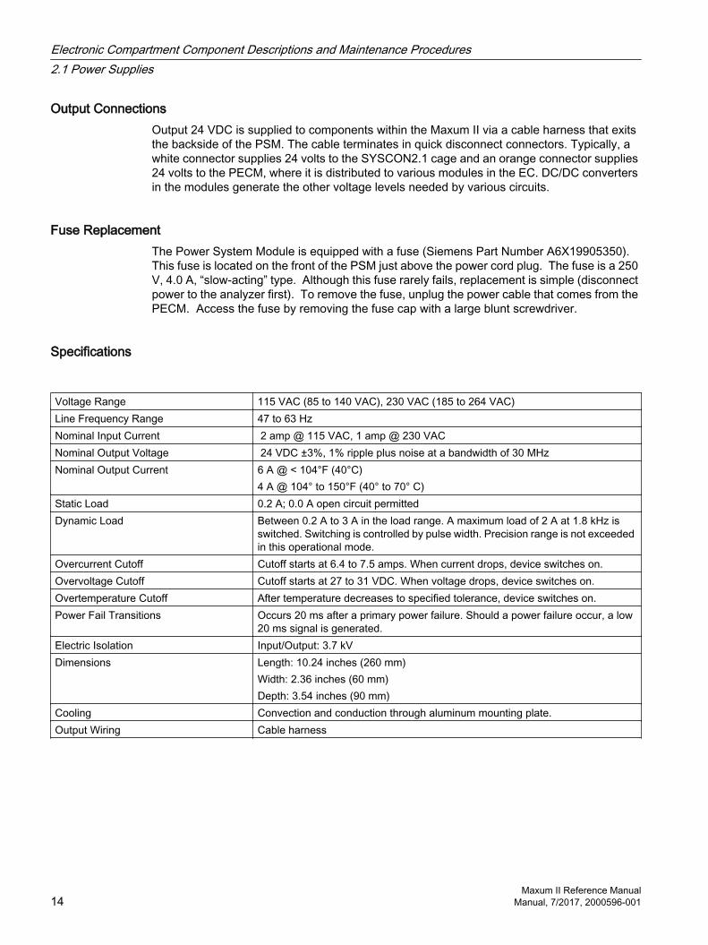
Output ConnectionsOutput 24 VDC is supplied to components within the Maxum II via a cable harness that exits the backside of the PSM. The cable terminates in quick disconnect connectors. Typically, a white connector supplies 24 volts to the SYSCON2.1 cage and an orange connector supplies 24 volts to the PECM, where it is distributed to various modules in the EC. DC/DC converters in the modules generate the other voltage levels needed by various circuits.
Fuse ReplacementThe Power System Module is equipped with a fuse (Siemens Part Number A6X19905350). This fuse is located on the front of the PSM just above the power cord plug. The fuse is a 250 V, 4.0 A, “slow-acting” type. Although this fuse rarely fails, replacement is simple (disconnect power to the analyzer first). To remove the fuse, unplug the power cable that comes from the PECM. Access the fuse by removing the fuse cap with a large blunt screwdriver.
Specifications
Voltage Range 115 VAC (85 to 140 VAC), 230 VAC (185 to 264 VAC)Line Frequency Range 47 to 63 HzNominal Input Current 2 amp @ 115 VAC, 1 amp @ 230 VACNominal Output Voltage 24 VDC ±3%, 1% ripple plus noise at a bandwidth of 30 MHzNominal Output Current 6 A @ < 104°F (40°C)
4 A @ 104° to 150°F (40° to 70° C)Static Load 0.2 A; 0.0 A open circuit permittedDynamic Load Between 0.2 A to 3 A in the load range. A maximum load of 2 A at 1.8 kHz is
switched. Switching is controlled by pulse width. Precision range is not exceeded in this operational mode.
Overcurrent Cutoff Cutoff starts at 6.4 to 7.5 amps. When current drops, device switches on.Overvoltage Cutoff Cutoff starts at 27 to 31 VDC. When voltage drops, device switches on.Overtemperature Cutoff After temperature decreases to specified tolerance, device switches on.Power Fail Transitions Occurs 20 ms after a primary power failure. Should a power failure occur, a low
20 ms signal is generated.Electric Isolation Input/Output: 3.7 kVDimensions Length: 10.24 inches (260 mm)
Width: 2.36 inches (60 mm)Depth: 3.54 inches (90 mm)
Cooling Convection and conduction through aluminum mounting plate.Output Wiring Cable harness
Electronic Compartment Component Descriptions and Maintenance Procedures2.1 Power Supplies
Maxum II Reference Manual14 Manual, 7/2017, 2000596-001

2.1.2 Replacement Procedure
Power Supply Location
Note
This procedure assumes that power is off in the analyzer.
The 24V power supply is easily accessed at the top of the electronics enclosure.
Replacement Steps
WARNING
Voltage dangerous to life exists in the electronics enclosure. Failure to follow proper safety procedures may result in injury or death.
Turn off line votage to the analyzer before disassembling power-supply components. Even though nothing appears to be operating, AC voltage can still be present on many of the components in the enclosure.
NOTICE
Obtain all permits that may be required to perform this work.
Observe local codes and obtain any required permits before starting the work.
The power supply has an integral bracket that slips under flanges in the top of the enclosure on the right side, and by two muts on threaded studs on the left side. Slots in the bracket allow removing the supply without completely removing the nuts.
12
3 45
6
77
A. B. C.
Figure 2-2 Removing the Power Supply Module
Electronic Compartment Component Descriptions and Maintenance Procedures2.1 Power Supplies
Maxum II Reference ManualManual, 7/2017, 2000596-001 15

1. Ensure that power has been disconnected from the analyzer.
2. Open the electronics enclosure door.
3. Unplug SYSCON power cable from the bottom of the SYSCON cage.
4. Unplug the PECM 24V cable.
5. Loosen nuts (1 in photo A above)
6. Slide the power supply forward enough to disengage the power-supply tabs from enclosure tabs as shown in photo below. (2 in photo A above)
7. Tilt the power supply clockwise to allow the tabs to clear the flanges. (3 in photo A above)
8. Drop the power supply off the nuts. (4 and 5 in photo B above)
9. Before completely removing the supply, unplug the safety ground wire from the spae lug on the back of the enclosure. (See 7 in the photo C Removing the Power Supply Module above.)
10.Slide the power supply out of encloure. (6 in photo B above)
To PECM power connector
To SYSCON
power connector
on bottom-left of cage
To safety
ground lug
on back wall
Mounting flanges on inside top of enclosure
Line-voltage
selector switch
Fuse holder
Line-cord connector
Figure 2-3 Power Supply Module Details
Reinstalling the power supplyThe new supply is installed using the steps in reverse order. It may be necessary to slightly bend the flange edges down to allow the supply bracket to engage the flanges. See C in the photo Removing the Power Supply Module above.
Electronic Compartment Component Descriptions and Maintenance Procedures2.1 Power Supplies
Maxum II Reference Manual16 Manual, 7/2017, 2000596-001

NoteVerify proper position of line-voltage selector switch and fuse value. Incorrect settings can damage the equipment.
See the information packet that was shipped with the analyzer for information on the individual analyzer.
Electronic Compartment Component Descriptions and Maintenance Procedures2.1 Power Supplies
Maxum II Reference ManualManual, 7/2017, 2000596-001 17
2.2 Power Entry and Control Module
2.2.1 PECM Overview
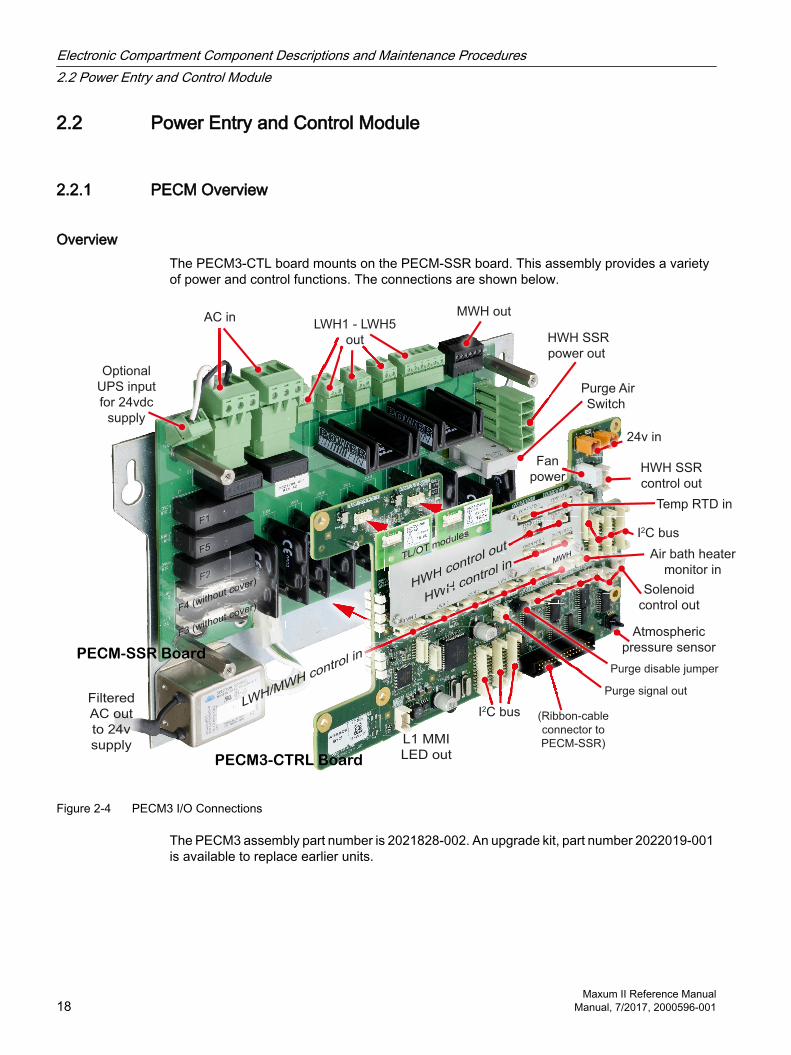
OverviewThe PECM3-CTL board mounts on the PECM-SSR board. This assembly provides a variety of power and control functions. The connections are shown below.
AC in
Optional
UPS input
for 24vdc
supply
LWH1 - LWH5
out
MWH out
Purge Air
Switch
24v in
Fan
powerHWH SSR
control out
I2C bus
I2C bus
Solenoid
control out
Atmospheric
pressure sensor
Air bath heater
monitor in
(Ribbon-cable
connector to
PECM-SSR)
Purge signal outLWH/MWH contro
l in
HWH control out
HWH control in
HW
ou
H contcontro
l
HWHWHWH H H cococontntntntntrorororol
contro
TL/OT modules
Temp RTD in
Filtered
AC out
to 24v
supply L1 MMI
LED out
MWH
HWH SSR
power out
PECM-SSR Board
PECM3-CTRL Board
F1F1
F5
F2
F5F5
F2F2F2F2F2F2F2F2F2F2F2F2F2
F4 (without cover)
Board
cover)
(without cov
F4 (witho
F4 (without
F3 (without cover)
Purge disable jumper
Figure 2-4 PECM3 I/O Connections
The PECM3 assembly part number is 2021828-002. An upgrade kit, part number 2022019-001 is available to replace earlier units.
Electronic Compartment Component Descriptions and Maintenance Procedures2.2 Power Entry and Control Module
Maxum II Reference Manual18 Manual, 7/2017, 2000596-001
2.2.2 Feature Additions
Improvements in PECM3-CTL from PECM-CTL Seven I2C connectors are provided compared to 4 on the previous PECM-CTL, eliminating
the need for a Wiring Distribution Board (WDB).
An Atmospheric pressure sensor has been added.
Improvements In PECM2 Assembly from Original PECMThe PECM design has changed since its original release. The newest version of this part is also used as the spare-part replacement for the previous version. The original PECM was a single electronic circuit board with a metal protective shield. It provided connection points for the electrical power coming into the Maxum GC and mounted low power electrical relays which could switch power to any electrical heater with a power rating of less than 200 watts.
The newest version of the module, PECM2, is a two part circuit board. One part connects the electrical power. The other part includes certain electronic circuits. Key features of the newer design are:
Easy access (no cover)
Two on-board temperature control circuits. May allow elimination of a DPM that is only used for temperature control, such as for heated valves or the methanator.
Additional medium-wattage heater circuit
Four connectors providing I2C and 24VDC power distribution have been added. This replaces some of the functions of the Wiring Distribution Board (WDB).
Includes solenoid valve control which eliminates the need for individual SVCM controller boards. When converting an older analyzer and eliminating original SVCM controller boards, additional long cables are required.
Improved low-profile fuse holders
LED indicators for air pressure switch on air-bath heater circuits
Built-in provision for connection of Uninterruptible Power Supply (UPS) for 24VDC circuits. The heaters are powered through different connectors to minimize the loading of the AC power needed for running the 24VDC circuits.
Electronic Compartment Component Descriptions and Maintenance Procedures2.2 Power Entry and Control Module
Maxum II Reference ManualManual, 7/2017, 2000596-001 19
2.2.3 PECM Functions
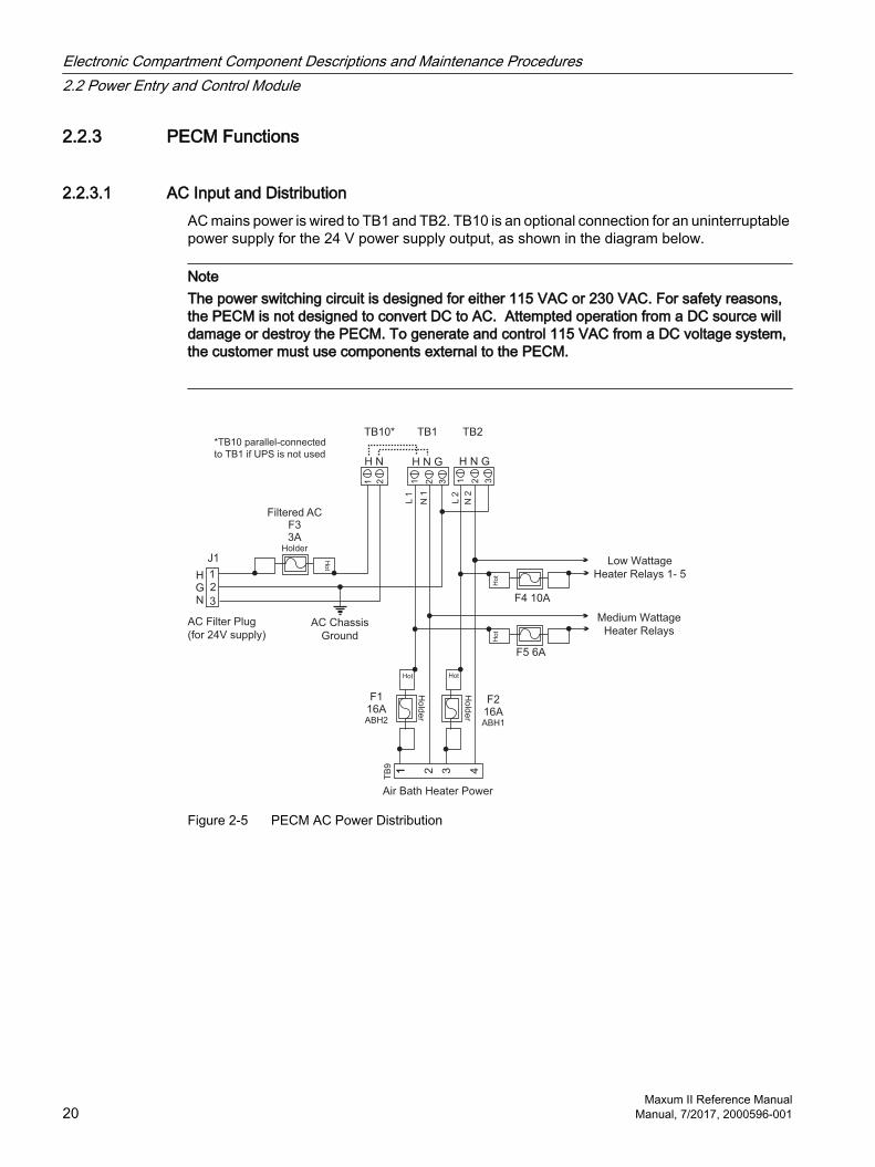
2.2.3.1 AC Input and DistributionAC mains power is wired to TB1 and TB2. TB10 is an optional connection for an uninterruptable power supply for the 24 V power supply output, as shown in the diagram below.
NoteThe power switching circuit is designed for either 115 VAC or 230 VAC. For safety reasons, the PECM is not designed to convert DC to AC. Attempted operation from a DC source will damage or destroy the PECM. To generate and control 115 VAC from a DC voltage system, the customer must use components external to the PECM.
*TB10 parallel-connected
to TB1 if UPS is not used
Ho
t
F5 6A
H N
TB10*
TB
9
Low Wattage
Heater Relays 1- 5
1 2 31 4
Air Bath Heater Power
Hot
Ho
lde
r
Hot
AC Chassis
Ground
F116AABH2
F216AABH1
Medium Wattage
Heater Relays
Ho
t
3
F4 10A
L2
N2
H N G
1 2 1 2
3AHolder
H N G
TB1 TB2
L1
N1
Ho
t
Filtered ACF3
J1
HGN
1
3
2
1 2 3
AC Filter Plug
(for 24V supply)
Ho
lde
r
Figure 2-5 PECM AC Power Distribution
Electronic Compartment Component Descriptions and Maintenance Procedures2.2 Power Entry and Control Module
Maxum II Reference Manual20 Manual, 7/2017, 2000596-001
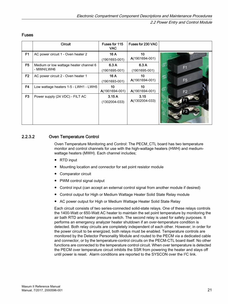
Fuses
Circuit Fuses for 115 VAC
Fuses for 230 VAC
F1 AC power circuit 1 - Oven heater 2 16 A(1901693-001)
10 A(1901694-001)
F5 Medium or low wattage heater channel 6 - MWH/LWH6
6.3 A(1901695-001)
6.3 A(1901695-001)
F2 AC power circuit 2 - Oven heater 1 16 A(1901693-001)
10 A(1901694-001)
F4 Low wattage heaters 1-5 - LWH1 - LWH5 10 A(1901694-001)
10 A(1901694-001)
F3 Power supply (24 VDC) - FILT AC 3.15 A(1302004-033)
3.15 A(1302004-033)
2.2.3.2 Oven Temperature ControlOven Temperature Monitoring and Control: The PECM_CTL board has two temperature monitor and control channels for use with the high-wattage heaters (HWH) and medium-wattage heaters (MWH). Each channel includes;
RTD input
Mounting location and connector for set point resistor module
Comparator circuit
PWM control signal output
Control input (can accept an external control signal from another module if desired)
Control output for High or Medium Wattage Heater Solid State Relay module
AC power output for High or Medium Wattage Heater Solid State Relay
Each circuit consists of two series-connected solid-state relays. One of these relays controls the 1400-Watt or 650-Watt AC heater to maintain the set point temperature by monitoring the air bath RTD and heater pressure switch. The second relay is used for safety purposes. It performs an emergency analyzer heater shutdown if an over-temperature condition is detected. Both relay circuits are completely independent of each other. However; in order for the power circuit to be energized, both relays must be enabled. Temperature controls are monitored by the Detector Personality Module and routed to the PECM via a dedicated cable and connector, or by the temperature-control circuits on the PECM-CTL board itself. No other functions are connected to the temperature control circuit. When over temperature is detected the PECM over temperature circuit inhibits the SSR from powering the heater and stays off until power is reset. Alarm conditions are reported to the SYSCON over the I2C link.
Electronic Compartment Component Descriptions and Maintenance Procedures2.2 Power Entry and Control Module
Maxum II Reference ManualManual, 7/2017, 2000596-001 21

Compare
Airflow
Loss
Shutdown
PECM Air Bath Oven
High-Wattage
Heater
Analog
SSR Pair
Air Pressure
Switch
Digital
Temp Control,
Temp Limit,
Overtemp RTDs
Temp
Setpoint
Modules
PWMI2C
Temperature
Control
Airflow Loss
Shutdown
HeaterAC
Line SSRa SSRb
SY
SC
ON
Figure 2-6 PECM Heater Control Functions
2.2.3.3 Communication and Power Distribution
The 24V power supply connects to one of two parallel power connectors, TB1 and TB2 on the PECM-CTL board. Another module can be powered from the other connector.
Each of the 7 I2C connectors also provides 24VDC power to the connected module.
A separate connector powers a 24V fan.
Electronic Compartment Component Descriptions and Maintenance Procedures2.2 Power Entry and Control Module
Maxum II Reference Manual22 Manual, 7/2017, 2000596-001

2.2.3.4 Onboard Solid State Relays
Low-Wattage Heater SSR ControlThe PECM has six solid-state relay circuits. These circuits can control low wattage (10 to 250 Watts) air bath heaters, heaters in the heated Flame Ionization and Flame Photometric detector housings or in heated sample injection valves, and can be adapted for on-off control of a sample valve or other device. The output voltage from each relay can either be 115 VAC or 230 VAC depending upon the mains supply voltage. Available outputs from the relays are on TB3 through TB8. Corresponding inputs are labeled LWH1 through LWH6. The LWH6 input controls the medium wattage heater (MWH) output. When a relay output is used for sample valve control, the supplied jumpers must be inserted in the corresponding input LWH1 through LWH4. (See Additional Relay Outputs below for using the individual SSRs in outputs 5 and 6.) For safety, since the power switching circuits are primarily designed for low-wattage air-bath heater control, each circuit has two series-connected SSRs, each being separately controlled. The jumper ties the two relays together to function as one output when they are not used for low wattage heater control. The circuitry is similar to the 1400-Watt High Wattage Heater Power Switching and it is controlled by signals from the Detector Personality Module (DPM) heater circuit. The diagram below shows a simplified schematic of the Low Wattage Heater Relay Circuit LWH4.
InputPowerACTB2
2
1
Neutral
Line
H4LW
TB5
PLUGCTRLH4LW
5A
13
4 2
1
24
35V
SSR4B
SSR4A
10kΩR47
10kΩ
R54
5V
4
2
6
5
1
3
J6
DGN
DetectPlug
BENSSR
BDET/CTRL
AENSSR
ADET/CTRL
LWH 4A Enabled
LWH 4A On
LWH 4B On
LWH 4 Plug Det
LWH 4B Enabled
Figure 2-7 LWH4 Heater Circuits
Electronic Compartment Component Descriptions and Maintenance Procedures2.2 Power Entry and Control Module
Maxum II Reference ManualManual, 7/2017, 2000596-001 23

Additional Relay OutputsRelay circuits LWH5 and LWH6 when used for purposes other than on/off control of low wattage heaters can supply four separate outputs. A simple jumper on pins 1 to 2 on output connector TB7 or TB8 makes this possible. With the jumper in place, each connector will provide two independent outputs; see the diagram below.
A&B Common Unused
AC Hot
SSRA Hot SSRA Load Hot
AC Neutral A Unused SSRA Load Neutral
SSRB Hot To LWH Hot Load SSRB Load Hot
AC Neutral B To LWH Neutral SSRB Load Neutral
TB7 (LWH5)or
TB8 (MWH)
Usage
HeaterSample
System Relays
Jumper
Jumper
Relay AC Supply Voltage
SolidStateRelay
Figure 2-8 LW5 & LW6 Relay Circuit Jumper Connections
2.2.3.5 Oven Functions
Temperature Monitoring and ControlThe PECM_CTL board has two temperature monitor and control channels for use with the high-wattage heaters (HWH). Each channel includes;
RTD input Mounting location and connector for
setpoint module Comparator circuit PWM control signal output
Control input (can accept an external control signal from another module if desired)
Control output for HWH SSR module AC power output for HWH SSR
The HWH control path is shown below.
Electronic Compartment Component Descriptions and Maintenance Procedures2.2 Power Entry and Control Module
Maxum II Reference Manual24 Manual, 7/2017, 2000596-001
Compare
Airflow
Loss
Shutdown
PECM Air Bath Oven
High-Wattage
Heater
Analog
SSR Pair
Air Pressure
Switch
Digital
Temp Control,
Temp Limit,
Overtemp RTDs
Temp
Setpoint
Modules
PWMI2C
Temperature
Control
Airflow Loss
Shutdown
HeaterAC
Line SSRa SSRb
SY
SC
ON
Figure 2-9 PECM Heater Control Functions
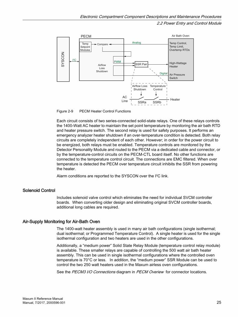
Each circuit consists of two series-connected solid-state relays. One of these relays controls the 1400-Watt AC heater to maintain the set point temperature by monitoring the air bath RTD and heater pressure switch. The second relay is used for safety purposes. It performs an emergency analyzer heater shutdown if an over-temperature condition is detected. Both relay circuits are completely independent of each other. However; in order for the power circuit to be energized, both relays must be enabled. Temperature controls are monitored by the Detector Personality Module and routed to the PECM via a dedicated cable and connector, or by the temperature-control circuits on the PECM-CTL board itself. No other functions are connected to the temperature control circuit. The connections are EMC filtered. When over temperature is detected the PECM over temperature circuit inhibits the SSR from powering the heater.
Alarm conditions are reported to the SYSCON over the I2C link.
Solenoid ControlIncludes solenoid valve control which eliminates the need for individual SVCM controller boards. When converting older design and eliminating original SVCM controller boards, additional long cables are required.
Air-Supply Monitoring for Air-Bath OvenThe 1400-watt heater assembly is used in many air bath configurations (single isothermal; dual isothermal; or Programmed Temperature Control). A single heater is used for the single isothermal configuration and two heaters are used in the other configurations.
Additionally, a “medium power” Solid State Relay Module (temperature control relay module) is available. These smaller relays are capable of controlling the 500 watt air bath heater assembly. This can be used in single isothermal configurations where the controlled oven temperature is 70°C or less. In addition, the “medium power” SSR Module can be used to control the two 250 watt heaters used in the Maxum airless oven configurations.
See the PECM3 I/O Connections diagram in PECM Overiew for connector locations.
Electronic Compartment Component Descriptions and Maintenance Procedures2.2 Power Entry and Control Module
Maxum II Reference ManualManual, 7/2017, 2000596-001 25

2.2.3.6 Electronic Enclosure Environment
Purge MonitoringThe PECM monitors the state of the purge condition for the analyzer. If a loss of purge is detected the purge switch is enabled. The purge control alarm signal is controlled by the SYSCON. The purge signal cable from SYSCON to PECM plugs into connector J1302 on the PECM2. Connection SW1 on the PECM2 is used to connect atmospheric reference for the purge switch.
When a purged enclosure is not required per the safety codes, connector J2 on the PECM2 can be used to disable the purge alarm. See the PECM3 I/O Connections diagram in PECM Overiew for connector locations.
Atmospheric Pressure Monitoring (New for PECM-CTL3)This sensor allows a Maxbasic program to measure the ambient atmospheric pressure for custom applications. A tube must be connected from the sensor (J44 on the PECM-SSR board) to the exterior of the EC.
L1 MMI LEDsMaintenance Panel Level 1 consists of LEDs on the outside of the analyzer door. It is intended for use in GCs that are not equipped with the full feature Maintenance Panel. The PECM supplies the control signals for Maintenance Panel Level 1, if equipped. For PECM-1, the Maintenance Panel Level 1 connects to position J17. See the PECM3 I/O Connections diagram in PECM Overiew for the location of connector J17.
Electronic Compartment Component Descriptions and Maintenance Procedures2.2 Power Entry and Control Module
Maxum II Reference Manual26 Manual, 7/2017, 2000596-001

Physical LocationThe PECM is mounted to the left inside wall of the EC cabinet. All fuses and electrical connections are readily accessible.
Figure 2-10 PECM3 Mounted in EC
Electronic Compartment Component Descriptions and Maintenance Procedures2.2 Power Entry and Control Module
Maxum II Reference ManualManual, 7/2017, 2000596-001 27

2.2.4 Replacement Procedure
General PrecautionsThe PECM is the entry point for the line voltage for the entire analyzer.
Note
Specific additional instructions are provided with tags placed on the Maxum II and in the custom application drawing package noted below. Installation must include all of the items noted in both of these as well as the manuals. The tagging and custom application drawing package are unique to the particular Maxum II.
This procedure must be performed by a user who has detailed knowledge of the Maxum. If a customer does not have the knowledge required for this procedure, then it is recommended that Siemens Field Service personnel be contracted to assist.
A tool kit including both standard and metric wrenches, Hex wrenches, and nut drivers is required to perform this procedure.
Before beginning replacement, be sure to save a current database of the application to be reloaded after the PECM is replaced in case this becomes necessary.
WARNING
Voltage dangerous to life is present on the PECM. Failure to observe proper safety measures can cause severe injury or death.
Before beginning to remove or install the PECM assembly, the power must be externally removed from the GC. AC power comes directly into this board for regulation and distribution in the electronics enclosure, so power must be removed and secured/tagged to prevent inadvertent application while this procedure is being performed.
2.2.4.1 Troubleshooting
PECM Status LEDsThe PECM3 should start automatically once power is applied. If the unit is not operational after applying power, then review the information below to aid in correcting the problem.
The most common issue with replacing the PECM3 is cables, wiring connections, and jumpers. Check all of the cable connections to ensure that they are seated and connected properly.
Electronic Compartment Component Descriptions and Maintenance Procedures2.2 Power Entry and Control Module
Maxum II Reference Manual28 Manual, 7/2017, 2000596-001

The alarm system can also provide direct information on alarms for an error. Review the alarms to see if they provide an indication of the problem. Each alarm has a written description that may provide an indication of the problem area.
The LEDs on the PECM board can help with troubleshooting problems. There are two sets of LEDs: one on each side of the front board as shown in the diagram to the right. The bottom set of three LEDs is the same as used on other boards (described below.) The left set is for the PECM software. (The other LEDs are not used for PECM1 replacement.) The corrective action to take for each of the LED indications is noted below with a correc‐tive action reference number on the diagram at the right. The normal state indication is shown in the diagram below.
PE
CM
-CT
RL P
CB
LEFT Heater Status RIGHT Heater status
Heater 1 Air Pressure
Heater 1 Power Activate
Heater 1 Temp Limit
Heater 1 Overtemp
Heater 2 Air Pressure
Heater 2 Power Activate
Heater 2 Temp Limit
Heater 2 Overtemp
Normal
Fault
Warning
Normal
Fault
Warning
PECM Status
Temperature
Controller
Status
PECM LEDs
State 11. If all units in this state, then power to the analyzer and/
or board is not active2. Reset the device or cycle power3. Check power connections to board (AC and 24VDC)4. Replace unit
Sta
te 1
- P
ow
er
off
Sta
te 2
- S
elf te
st
Sta
te 3
- A
dd
ress a
ssig
nm
en
t
Sta
te 4
- N
orm
al o
pe
ratio
n
Sta
te 5
- W
arn
ing
co
nd
itio
n; d
ata
go
od
te
mp
ora
rily
Sta
te 6
- F
au
lt c
on
ditio
n; d
ata
in
va
lid
Normal
Fault
Warning
PECM LED Interpretation
State 21. Reset the device or cycle analyzer power2. Replace unitState 31. Reset the device or cycle analyzer power2. If all modules are in State 3, then SNECON is not
communicating (check cabling and connections)3. Replace unitState 4 Normal OperationState 51. Reset the device or cycle power2. Check communication cable connectionsState 61. Reset the device or cycle power2. Check communication cable connections3. Check for missing Temp Limit setpoint boards4. Check for shorted or open RTDs5. Replace the unit6. Replace other connected units
Electronic Compartment Component Descriptions and Maintenance Procedures2.2 Power Entry and Control Module
Maxum II Reference ManualManual, 7/2017, 2000596-001 29
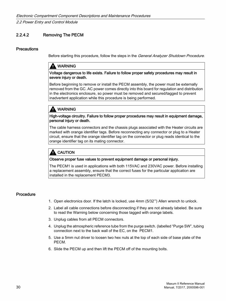
2.2.4.2 Removing The PECM
PrecautionsBefore starting this procedure, follow the steps in the General Analyzer Shutdown Procedure.
WARNING
Voltage dangerous to life exists. Failure to follow proper safety procedures may result in severe injury or death.
Before beginning to remove or install the PECM assembly, the power must be externally removed from the GC. AC power comes directly into this board for regulation and distribution in the electronics enclosure, so power must be removed and secured/tagged to prevent inadvertent application while this procedure is being performed.
WARNING
High-voltage circuitry. Failure to follow proper procedures may result in equipment damage, personal injury or death.
The cable harness connectors and the chassis plugs associated with the Heater circuits are marked with orange identifier tags. Before reconnecting any connector or plug to a Heater circuit, ensure that the orange identifier tag on the connector or plug reads identical to the orange identifier tag on its mating connector.
CAUTION
Observe proper fuse values to prevent equipment damage or personal injury.
The PECM1 is used in applications with both 115VAC and 230VAC power. Before installing a replacement assembly, ensure that the correct fuses for the particular application are installed in the replacement PECM3.
Procedure1. Open electronics door. If the latch is locked, use 4mm (5/32’”) Allen wrench to unlock.
2. Label all cable connections before disconnecting if they are not already labeled. Be sure to read the Warning below concerning those tagged with orange labels.
3. Unplug cables from all PECM connectors.
4. Unplug the atmospheric reference tube from the purge switch. (labelled “Purge SW”, tubing connection next to the back wall of the EC, on the PECM1.
5. Use a 5mm nut driver to loosen two hex nuts at the top of each side of base plate of the PECM.
6. Slide the PECM up and then lift the PECM off of the mounting bolts.
Electronic Compartment Component Descriptions and Maintenance Procedures2.2 Power Entry and Control Module
Maxum II Reference Manual30 Manual, 7/2017, 2000596-001
2.2.4.3 Installing The New PECM
Procedure1. On the replacement PECM3 assembly do the following:
– Set the Purge Disable jumper JP2 to the same setting as the PECM being replaced.
– Install the appropriate fuses for either 115VAC or 230VAC in Fuses F1 and F2 and install fuse covers.
– Move jumper cables or termination plugs to the replacement PECM.
– Move the TL/OT modules from the old PECM to the replacement PECM, in the mounting locations marked “TEMP CONTROL 1” and TEMP CONTROL 2”. These are required to avoid false alarm codes.
– If Heater Termination Plugs are installed in the old PECM instead of cables at the positions marked “TEMP RTD 1” and “TEMP RTD 2”, move these to identical locations on the replacement PECM. The plugs disable the PECM temperature circuits, including the LEDs.
2. Ensure that there are no wires behind the mounting position of the PECM.
3. Because the atmospheric Purge switch SW1 is near the back wall after the PECM is installed, if desired, the Purge tube may be installed on SW1 before mounting the PECM in the next step.
4. Install the replacement PECM on the two mounting bolts.
5. Tighten the two 5mm hex nuts.
6. Start at the back of new controller and plug in the following cables (see the connector identification illustrations)
– If not already connected in step 12, connect the Purge switch SW1 (tubing connection)
– Relay power plug TB9 and Heater Relay Control cable
– Fan power cable plug J18, and 24VDC power cables to the orange TB1 and TB2 on top board (there are TB1 and TB2 AC connectors on the bottom board as well - see illustration at right.)
– I2C connections (J24 - J26, J30 - J33)
– Low wattage heater connections (TB8, TB3 to TB5, and LWH1 to LWH6)
– AC inputs (TB1, TB2, & TB10.)
– Heater pressure switch (J10) (If no cable, then a jumper is needed.)
7. When replacing in a unit that has a MMI-1, then connect the MMI LED cable to J17.
8. Connect the Purge Signal cable to J1302.
9. Move 24V cable (from power supply) from WDB J1 to PECM3 TB1.
10.Add 24V power cable, 2021837-001 from PECM3 TB2 to WDB J1.
Electronic Compartment Component Descriptions and Maintenance Procedures2.2 Power Entry and Control Module
Maxum II Reference ManualManual, 7/2017, 2000596-001 31

11.Ensure the correct fuses are in the correct positions, as shown in PECM AC Power Distribution illustration.
12.When the procedure is completed, follow the steps in the General Analyzer Startup Procedure.
2.3 System Controller Version 2.1 (SYSCON2.1)
2.3.1 DescriptionThe System Controller (SYSCON2.1) is a combination of two interconnected boards that together function as the control processor and motherboard for the Maxum analyzer.
The SYSCON2.1 consists of two boards, the Communication and Analytical Control (CAC3) board and the SYSCON Interface Board (SIB3). The CAC3 contains the processor and memory functions for the SYSCON2.1 as well as control of external Ethernet communications (via the Ethernet Switch Board). The CAC3 is mounted on and operates in conjunction with the SIB3. With the exception of external Ethernet, the SIB3 contains all interfaces provided by the SYSCON2.1.
The CAC3 on the SYSCON2.1 stores the analyzer application database, combines all data results, and performs additional high-level data processing and calculations. All network communications, maintenance panel and analyzer functions are also coordinated by the SYSCON2.1. The SYSCON2.1 provides communication between the Controller Board, I/O Boards and the EC operating modules.
More information about the SYSCON can be found in the System Controller version 2 (SYSCON2.1) Installation Manual (Siemens part number A5E02643617001).
Additional Functions
Processing and communicating the measurement values
Controlling system functions, such as calibration
Display and operator control Controlling associated systems, such as
gas supply Generating reports
Software SupportThe SYSCON2.1 is supported only by software version 5.2 or greater.
Electronic Compartment Component Descriptions and Maintenance Procedures2.3 System Controller Version 2.1 (SYSCON2.1)
Maxum II Reference Manual32 Manual, 7/2017, 2000596-001
2.3.2 Mechanical
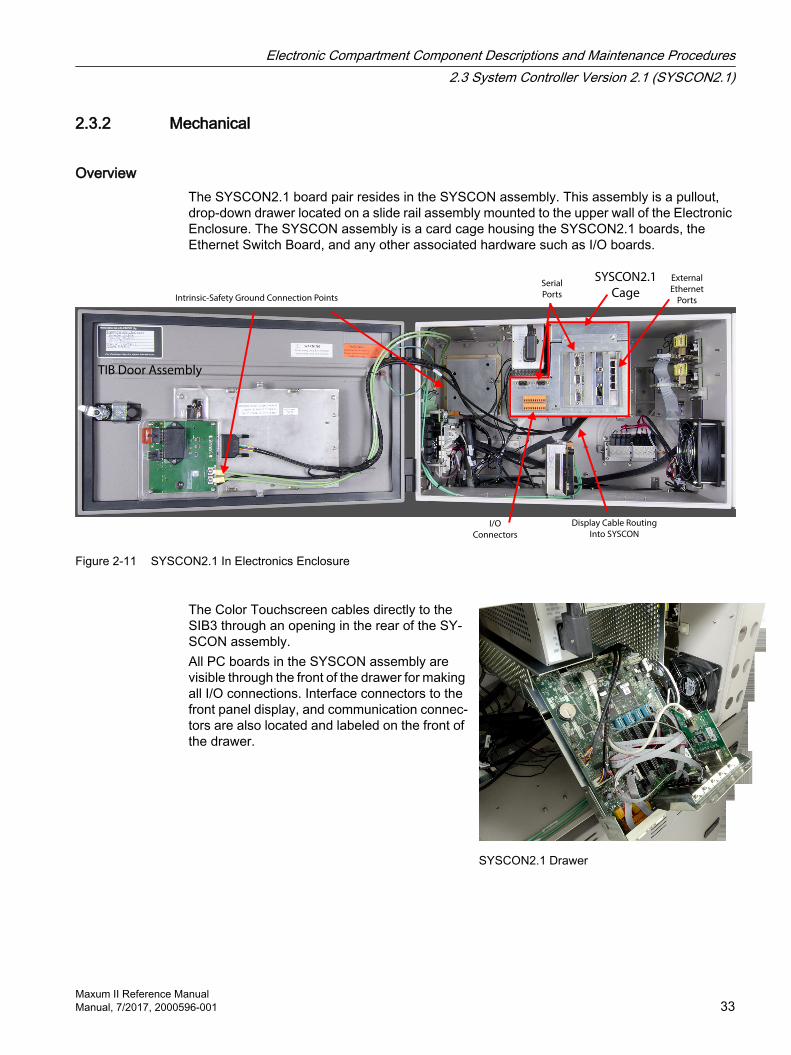
OverviewThe SYSCON2.1 board pair resides in the SYSCON assembly. This assembly is a pullout, drop-down drawer located on a slide rail assembly mounted to the upper wall of the Electronic Enclosure. The SYSCON assembly is a card cage housing the SYSCON2.1 boards, the Ethernet Switch Board, and any other associated hardware such as I/O boards.
I/O
Connectors
Serial
Ports
SYSCON2.1
Cage
External
Ethernet
Ports
Display Cable Routing
Into SYSCON
Intrinsic-Safety Ground Connection Points
TIB Door Assembly
Figure 2-11 SYSCON2.1 In Electronics Enclosure
The Color Touchscreen cables directly to the SIB3 through an opening in the rear of the SY‐SCON assembly.All PC boards in the SYSCON assembly are visible through the front of the drawer for making all I/O connections. Interface connectors to the front panel display, and communication connec‐tors are also located and labeled on the front of the drawer.
SYSCON2.1 Drawer
Electronic Compartment Component Descriptions and Maintenance Procedures2.3 System Controller Version 2.1 (SYSCON2.1)
Maxum II Reference ManualManual, 7/2017, 2000596-001 33

2.3.3 SYSCON2.1 Components
2.3.3.1 Communication and Control Board (CAC3)The Communication and Control board (CAC) is a standardized, single-board central processing unit for intended for use in Siemens products. For the Maxum family of products the third generation of the CAC board (CAC3) is used.
The CAC3 includes an on-board 10/100 Ethernet controller, used for connection to external Ethernet. This is connected via a short RJ-45 patch cable to the Ethernet Switch Board, which resides in a card slot on the SIB3.
More information and details pertaining to the CAC3 can be found in the System Controller version 2.1 (SYSCON2.1) Installation Manual (Siemens part number A5E02643617001).
Figure 2-12 CAC3 Board (Part Number A5E02599492004)
Electronic Compartment Component Descriptions and Maintenance Procedures2.3 System Controller Version 2.1 (SYSCON2.1)
Maxum II Reference Manual34 Manual, 7/2017, 2000596-001
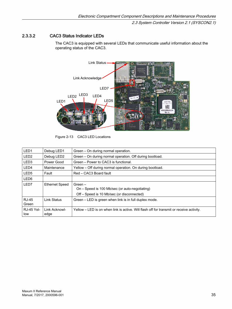
2.3.3.2 CAC3 Status Indicator LEDsThe CAC3 is equipped with several LEDs that communicate useful information about the operating status of the CAC3.
Link Acknowledge
LED4
LED5
LED7
LED1
LED2LED3
Link Status
Figure 2-13 CAC3 LED Locations
LED1 Debug LED1 Green – On during normal operation.LED2 Debug LED2 Green – On during normal operation. Off during bootload.LED3 Power Good Green – Power to CAC3 is functional.LED4 Maintenance Yellow – Off during normal operation. On during bootload.LED5 Fault Red – CAC3 Board faultLED6 LED7 Ethernet Speed Green –
On – Speed is 100 Mb/sec (or auto-negotiating) Off – Speed is 10 Mb/sec (or disconnected)
RJ-45 Green
Link Status Green – LED is green when link is in full duplex mode.
RJ-45 Yel‐low
Link Acknowl‐edge
Yellow – LED is on when link is active. Will flash off for transmit or receive activity.
Electronic Compartment Component Descriptions and Maintenance Procedures2.3 System Controller Version 2.1 (SYSCON2.1)
Maxum II Reference ManualManual, 7/2017, 2000596-001 35

2.3.3.3 SIB
SYSCON Interface Board (SIB3) Overview
Compared to the SYSCON2 in previous Maxum II analyzers, the SIB3/CAC3 together with the Color Touchscreen equipped with a TIB module replaces the SIB2/CAC3 and Color Touchscreen equipped with a CIM module. This simplifies the internal cabling in the electronics enclosure.
The SYSCON Interface Board version 3 (SIB3) is a board, with the CAC3 mounted on it, performs the function of the SYSCON2.1. Unlike the CAC3, the SIB3 is specific to the Maxum family of products (including the Maxum, the Maxum II, NAU). The combined SIB3 and CAC3 are an electrically and mechanically compatible replacement for the legacy SYSCON board in the Maxum.
Electronic Compartment Component Descriptions and Maintenance Procedures2.3 System Controller Version 2.1 (SYSCON2.1)
Maxum II Reference Manual36 Manual, 7/2017, 2000596-001

SIB3 LEDs
LED LocationsThe SIB3 has several LEDs that indicate useful information about the operating status of various interfaces.
I2C-Pullup
Active LEDs
3210
PCI Slot LEDs
Reset
I/O Connector
DI Mode
Switch
(Set to Mode 2)
CAN
Bridge
LEDs
Power LEDs
Internal
Ethernet
to SNECON
LEDs
CAC3
I2C LEDs
Figure 2-14 SIB3 LEDs and Switches
Electronic Compartment Component Descriptions and Maintenance Procedures2.3 System Controller Version 2.1 (SYSCON2.1)
Maxum II Reference ManualManual, 7/2017, 2000596-001 37

Power LEDsLocated at the back of the board near the RJ 45 connector
Description Color and MeaningPower Green – 3.3V power is available. Should be on at all timesPower Bad Red – Power is faulty or SYSCON hardware reset switch is being pressedCAC Conn Bad Red – Connection from the SIB3 to the CAC3 is faulty or incomplete. After power up, this
LED should turn off once CAC3 to SIB3 connection is completely initialized.
I2C Bus LEDs, Buses A and BLocated next to I2C Bus connectors
Description Color and MeaningLED2/5 Norm/Comm Dim Green – I2C Bus is normal
Bright Green - I2C Bus is communicatingLED3/6 Warning Yellow – Warning on the I2C BusLED4/7 Fault Red –I2C Bus fault
I2C Bus Pullup-Active LEDsLocated next to battery holder
Description Color and MeaningLED19, 20 The Auto-pullup feature is supplying pullup current on the I2C Bus.
Can Bridge LEDsLocated to the left of the far left PCI slot
Description Color and MeaningLED16 Ready/Comm Dim Green – Can Bridge is normal
Bright Green – Can Bridge is communicatingLED17 Warning Yellow – Warning on the Can BridgeLED15 Fault Red – Can Bridge fault
Can I/O LEDsLocated next to far left CAN direct connector, CAN direct 5
Description Color and MeaningLED8 TX Green – On when a valid CAN I/O message (other than a heartbeat reply) has been received
and queued for processingLED9 RX Green – On when a CAN message (other than a heartbeat transmission) has been queued
for sending to the CAN hardware
Electronic Compartment Component Descriptions and Maintenance Procedures2.3 System Controller Version 2.1 (SYSCON2.1)
Maxum II Reference Manual38 Manual, 7/2017, 2000596-001

Description Color and MeaningLED10 Heartbeat Green – Flashes once for each heartbeat message transmitted. This LED will flash once
every 1.5 seconds for each active CAN cardLED11 Fault Red – On when an error state is detected on the CAN bus hardware
PCI Slot LEDsLocated between PCI slots
Description Color and MeaningLED14 Slot 0 Fault Red – Overcurrent or thermal shutdown on PCI slot 0LED13 Slot 1 Fault Red – Overcurrent or thermal shutdown on PCI slot 1LED18 Slot 2 Fault Red – Overcurrent or thermal shutdown on PCI slot 2LED12 Slot 3 Fault Red – Overcurrent or thermal shutdown on PCI slot 3
Internal Ethernet LEDsLocated next to and on SIB3 RJ-45 connector
Description Color and MeaningGreen LED on RJ-45 Green – LED is green when link is in full duplex modeYellow LED on RJ-45 Yellow – LED is on when link is active. Will flash off for transmit or receive activity.LED1 Speed Green –
On – Speed is 100 Mb/sec (or auto-negotiating)Off – Speed is 10 Mb/sec (or disconnected)
Electronic Compartment Component Descriptions and Maintenance Procedures2.3 System Controller Version 2.1 (SYSCON2.1)
Maxum II Reference ManualManual, 7/2017, 2000596-001 39

SIB3 ConnectorsOther than external Ethernet, the SIB provides all interfaces for the SYSCON2.1. The connections are described below. All connectors in the SYSCON2.1 have the same pin assignments as the corresponding connectors in the original SYSCON, except where noted below.
4523
Reset
(Legacy)
CAC3
3210
Power
Purge
CAN
Internal
CAN
Direct
Serial
Port 4
Serial
Port 3
Ne
two
rk E
xp
an
sio
n S
lot
for
Eth
ern
et S
witch
Bo
ard
PCI SlotsCAN Bus
Reset
I/O Connector
I/O Mode
Switch
Serial Port 1
Serial Port 2
Color
Touchscreen
SYSCON
Debug
Ethernet
(to Ethernet
Switch)
Ethernet
to SNECON
(if used)
Maintenance
Panel (Legacy)I2C B
I2C A
32 54
Figure 2-15 SYSCON2.1 Connections
Electronic Compartment Component Descriptions and Maintenance Procedures2.3 System Controller Version 2.1 (SYSCON2.1)
Maxum II Reference Manual40 Manual, 7/2017, 2000596-001
PCI and CAN Direct SlotsThe PCI slots on the SIB accommodate a variety of special function cards, including I/O boards or an ANCB board. Four PCI slots are equipped in the SYSCON2.1; however, typically only three slots are available for use in the standard configuration, because one SYSCON slot is used for serial/debug port hardware.
In addition to PCI type cards, the card slots can also accommodate Maxum CAN I/O cards. The small green connector in line with the PCI slot allows CAN I/O cards to be installed in the slot. When a CAN card is installed, the green connector provides the power and CAN signals for the card. The PCI slot connector has no electrical connection for CAN cards.
NoteOnly use cards specified and sold by Siemens for the SYSCON2.1. Installation of a card that is not approved by Siemens into a SYSCON2.1 PCI slot, may damage both the card and the SYSCON2.1.
Network Expansion SlotThe Ethernet Switch Board (or Ethernet Switch Board with Fiber) plugs into this connector, located on the far right side of the SYSCON2.1. The connector slot provides power to the Ethernet Switch, but no communication. All communication between the Ethernet Switch and the SYSCON2.1 is through a short CAT5 Ethernet Cable that connects from the CAC3 to the Ethernet Switch.
Electronic Compartment Component Descriptions and Maintenance Procedures2.3 System Controller Version 2.1 (SYSCON2.1)
Maxum II Reference ManualManual, 7/2017, 2000596-001 41

Serial Ports SYSCON Debug – This serial RS-232 port provides the SYSCON2.1 debug function on
the CAC3. The debug port has no support for hardware handshake. The debug port is accessed via a DB9 connector on the front of the SYSCON assembly cage.
Serial Ports 1 and 2 – The SYSCON2.1 is equipped with two serial ports, each ground-isolated and configurable for RS-232 or RS-485. Both ports support RTS/CTS hardware handshake. Maximum supported data rate on the serial ports is 115200 bits/second. Serial Port 1 supports Modbus and Serial Port 2 may be used to support a printer.
NoteRS-485 Operation
When configured for RS-485 operation, the serial ports are designed to comply with the Profibus standard. This results in a different pinout than for the previous version of SYSCON (pins 8 and 2 reversed). For backward Modbus RS-485 compatibility when replacing a SYSCON+ with a SYSCON2.1, an adapter cable (part number A5E02283873001) is available.
DB-9 Pin RS-232 Signal RS-485 Modbus Signal1 - -2 RX %v power3 TX Line B (RxD+/TxD+)4 - -5 GND Common6 - -7 RTS -8 CTS Line A (RxD-/TxD-)9 - -
Serial Ports 3 and 4 – These two serial ports, equipped on the same slot connector as the SYSCON Debug port, are not active in software release 5.0.
I2C BusThe I2C connectors are shown in the upper right corner of the SYSCON2.1 Connections photo. Two I2C buses are equipped on the SYSCON2.1. These are labeled I2C Bus A and I2C Bus B.
I2C Bus A includes the two connectors on the right as shown in the SYSCON2.1 Connections photo. I2C Bus A is dedicated and hard wired to the CAN Bridge function. This allows the new SYSCON2.1 to interface with legacy CAN I/O cards in the PCI slots.
I2C Bus B includes the three I2C connectors on the left as shown in the SYSCON2.1 Connections photo. I2C Bus B is supports2 future configuration changes in the Maxum II.
Electronic Compartment Component Descriptions and Maintenance Procedures2.3 System Controller Version 2.1 (SYSCON2.1)
Maxum II Reference Manual42 Manual, 7/2017, 2000596-001
ResetsThe SYSCON2.1 has a pushbutton reset switch at the front of the board. This switch may be accessed via the front of the newest version SYSCON assembly cage. The second connection consists of two pin connections at the back of the board (top left of the SIB connections photo) second connection operates using a simple loop closure, and supports legacy SYSCON assembly cages that provide a separate wired pushbutton reset. Both connections allow the user to initiate a hard reset of the SYSCON (same as initial power up).
PurgeThe purge detect signal is received from the PECM and handled by the SYSCON as a digital input to generate a purge alarm.
Display ConnectorsInterface and power for the Color Touchscreen connect to the SYSCON2.1 using a cable assembly. This cable runs directly from two connectors on the SIB, out through tthe back of the SYSCON cage, to the Color Touchscreen panel.
PowerThe 24 V power supply mounted beside the SYSCON cage powers the SYSCON2.1 directly through a cable that plugs into the bottom of the cage. On-board power conversion derives the other voltages needed for operation.
Note
The real-time clock on the CAC3 board is powered by a backup circuit on the SIB. Older SIBs may have a battery in the backup circuit. Because the back-up circuit is located on the SIB board while the real time clock is on the CAC3 board, if the CAC3 board is disconnected from the SIB, then backup power is lost. The time and date must then be set on the analyzer.
IO ConnectionsThe SYSCON has the following channels:
x4 digital output relay channels providing a normally closed (NC) and normally open (NO) with common.
x4 digital input channels. Straight contact closure and sourcing from the device to trigger state change is provided. See DI_SINK_SOURCE section for more explanation.
x2 analog output current channels. Output ranges are 0 to 20mA, 4 to 20mA, 3.8 to 20.5mA (NAMUR) and 0 to 25mA. The last two are possible with latest versions of software only (ver 4.3 and later).
DO1 is for system alarms (Fault only) and cannot be addressed.
AO1 is used for the chart recorder but may be used as an AO. If the chart recorder is turned on it will control the AO’s output.
The field wiring is connected to terminals 1 through 12 and 13 through 24.
Electronic Compartment Component Descriptions and Maintenance Procedures2.3 System Controller Version 2.1 (SYSCON2.1)
Maxum II Reference ManualManual, 7/2017, 2000596-001 43
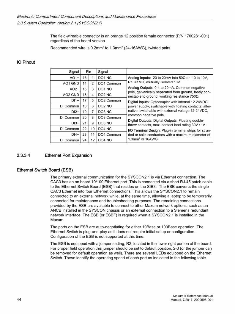
The field-wireable connector is an orange 12 position female connector (P/N 1700281-001) regardless of the board version.
Recommended wire is 0.2mm2 to 1.3mm2 (24-16AWG), twisted pairs
IO Pinout
Signal Pin Signal AO1+ 13 1 DO1 NC Analog Inputs: -20 to 20mA into 50Ω or -10 to 10V,
R10=1MΩ, mutually isolated 10VAnalog Outputs: 0-4 to 20mA. Common negative pole, galvanically separated from ground, freely con‐nectable to ground; working resistance 750Ω.Digital Inputs: Optocoupler with internal 12-24VDC power supply, switchable with floating contacts; alter‐native: switchable with external voltage 12-24VDC, common negative pole.Digital Outputs: Digital Outputs: Floating double-throw contacts, max. contact load rating 30V / 1AI/O Terminal Design: Plug-in terminal strips for stran‐ded or solid conductors with a maximum diameter of 1.3mm2 or 16AWG.
AO1 GND 14 2 DO1 CommonAO2+ 15 3 DO1 NO
AO2 GND 16 4 DO2 NCDI1+ 17 5 DO2 Common
DI Common 18 6 DO2 NODI2+ 19 7 DO3 NC
DI Common 20 8 DO3 CommonDI3+ 21 9 DO3 NO
DI Common 22 10 DO4 NCDI4+ 23 11 DO4 Common
DI Common 24 12 DO4 NO
2.3.3.4 Ethernet Port Expansion
Ethernet Switch Board (ESB)The primary external communication for the SYSCON2.1 is via Ethernet connection. The CAC3 has an on board 10/100 Ethernet port. This is connected via a short RJ-45 patch cable to the Ethernet Switch Board (ESB) that resides on the SIB3. The ESB converts the single CAC3 Ethernet into four Ethernet connections. This allows the SYSCON2.1 to remain connected to an external network while, at the same time, allowing a laptop to be temporarily connected for maintenance and troubleshooting purposes. The remaining connections provided by the ESB are available to connect to other Maxum network options, such as an ANCB installed in the SYSCON chassis or an external connection to a Siemens redundant network interface. The ESB (or ESBF) is required when a SYSCON2.1 is installed in the Maxum.
The ports on the ESB are auto-negotiating for either 10Base or 100Base operation. The Ethernet Switch is plug-and-play as it does not require initial setup or configuration. Configuration of the ESB is not supported at this time.
The ESB is equipped with a jumper setting, R2, located in the lower right portion of the board. For proper field operation this jumper should be set to default position, 2-3 (or the jumper can be removed for default operation as well). There are several LEDs equipped on the Ethernet Switch. These identify the operating speed of each port as indicated in the following table.
Electronic Compartment Component Descriptions and Maintenance Procedures2.3 System Controller Version 2.1 (SYSCON2.1)
Maxum II Reference Manual44 Manual, 7/2017, 2000596-001

LEDs for external connectors count from the bottom up (e.g. bottom LED is for top connector).
LED Meaning Description1 On=100Mb Off=10Mb Internal RJ-45 Connector to CAC32 External Top RJ-45 Connector3 External Second RJ-45 Connector4 External Third RJ-45 Connector5 External Bottom RJ-45 Connector
Figure 2-16 Ethernet Switch Board (ESB, Part Number A5E02368691001)
Ethernet Switch Board with Fiber (ESBF)The Ethernet Switch Board with Fiber (ESBF) is similar to the Ethernet Switch Board (ESB) described previously. The primary difference is that for the ESBF one of the 10/100Base-T connectors has been replaced with a 100Base-FX 1300 nm fiber optic connection with duplex ST® connectors. This fiber connection is not compatible with 10 megabit fiber systems.
As can be seen in Figure 2-22 on the following page, the ESBF is equipped with two edge connectors, one on the top of the board and one on the bottom. The board is designed in this manner to support its use in either the network slot (slot 5) of a SYSCON2.1 or in a PCI slot of a SYSCON2.1 or legacy SYSCON1. The slot edge connectors are labeled on the board as “SYSCON2.1 NETWORK SLOT” and “SYSCON/PCI SLOT”. Only one Ethernet Switch may be used in an analyzer for external Ethernet communication.
However, It is possible to use an ESB in slot 5 for external Ethernet, and an ESBF in another slot in the alternate configuration for internal Ethernet in cases where legacy SNECON modules must be used.
Electronic Compartment Component Descriptions and Maintenance Procedures2.3 System Controller Version 2.1 (SYSCON2.1)
Maxum II Reference ManualManual, 7/2017, 2000596-001 45

Figure 2-17 Ethernet Switch Board with Fiber (ESBF, Part Number A5E02555919001)
Multiple Mode Use of ESBFThe unique dual edge connector allows the ESBF to be used in both the SYSCON2.1 and legacy SYSCON. The ESBF may be installed in the following configurations:
Default – In the default configuration, the ESBF installs in the network slot of the SYSCON2.1 (far right slot 5). In this configuration the slot edge connector labeled “SYSCON2.1 NETWORK SLOT” is used (the fiber optic connection is on the top in this configuration).
SYSCON2.1 Expansion – ESBF is capable of installing in one of the PCI slots (slots 1 through 4, counting from left) of the SYSCON2.1. This configuration is used in the SYSCON2.1 when communicating with more than one SNE or when additional Ethernet communication ports are required. In this configuration the ESBF is turned “upside-down” and the “SYSCON/PCI SLOT” slot edge connector is used (the fiber optic connection is on the bottom in this configuration).
SYSCON1 Enhancement – ESBF installs in an empty PCI slot (slots 1 through 4, counting from left). This allows the original SYSCON1 to communicate to more than one Ethernet device at the same time (such as communication to a local laptop computer while still connected to the network). This also allows for easy configuration to support fiber Ethernet connection. In this configuration the ESBF is turned “upside-down” and the “SYSCON/PCI SLOT” slot edge connector is used (the fiber optic connection is on the bottom in this configuration).
To support the dual edge connector configuration, the ESBF is equipped with a special reversible bracket. This bracket is detached and turned upside down when the board is installed upside down in a PCI slot. To reverse the bracket, unscrew it and turn it upside down. Then, connect the bracket using the opposite set of holes to align the bracket appropriately.
Electronic Compartment Component Descriptions and Maintenance Procedures2.3 System Controller Version 2.1 (SYSCON2.1)
Maxum II Reference Manual46 Manual, 7/2017, 2000596-001

Figure 2-18 ESBF Bracket Position (Default at left, Alternate at right)
Electronic Compartment Component Descriptions and Maintenance Procedures2.3 System Controller Version 2.1 (SYSCON2.1)
Maxum II Reference ManualManual, 7/2017, 2000596-001 47

2.3.4 Maintenance Overview
Board ReplacementA failure in the SYSCON2.1 will generally interrupt communication between the GCP networkbased software and the detectors. A simplified view of the system is shown below.
CAC3CAN
RS485
RS232
Digital Communication
DC Supply
AC Supply
Analyzers
GCP
Ethernet
Ethernet
Switch
(optional)
I/O
Boards
(I2C)
120/240VAC
120/240VAC
120/240VAC
24VDC
Heaters
24 V
Supply
PECM
SSR
Board
24VDC
24VDC
I2C
24VDC
I2C
24VDC
EPCs
SVCMsEthernet
I2C I2C
GCP
Color
Touch
Display SYSCON
(SIB3)
PECM
Controller
Board
DPMs
Figure 2-19 Power Distribution and Communication Paths
Most problems can be resolved by checking interconnects between cable, boards, and connectors. If a component must be replaced, the following sections give detailed procedures.
Remote Database BackupBecause these procedures separate the CAC3 memory from the backup-battery voltage on the SIB3, the database must be backed up to a workstation on the network or directly connected.
2.3.5 Service Procedures
Preparing to Replace A ComponentThe analyzer must be shut down using the General Analyzer Shutdown Procedure in the Maxum Edition II Analyzer General Maintenance Manual.
Electronic Compartment Component Descriptions and Maintenance Procedures2.3 System Controller Version 2.1 (SYSCON2.1)
Maxum II Reference Manual48 Manual, 7/2017, 2000596-001

Replacing A CAC3The CAC3 memory content depends on backup-battery voltage from the SIB3. When the CAC3 is removed from the SIB3, the memory content is lost. Observe safe ESD handling procedures.
1. Disconnect the ethernet cable from the CAC3 board.
2. Remove the two 2mm screws and o-rings as shown in the illustration below. Early SIB3s had threaded studs, with two nuts with o-rings.
3. Remove the CAC3 by gently pulling it straight up. Avoid rocking or tilting motions.
Electronic Compartment Component Descriptions and Maintenance Procedures2.3 System Controller Version 2.1 (SYSCON2.1)
Maxum II Reference ManualManual, 7/2017, 2000596-001 49
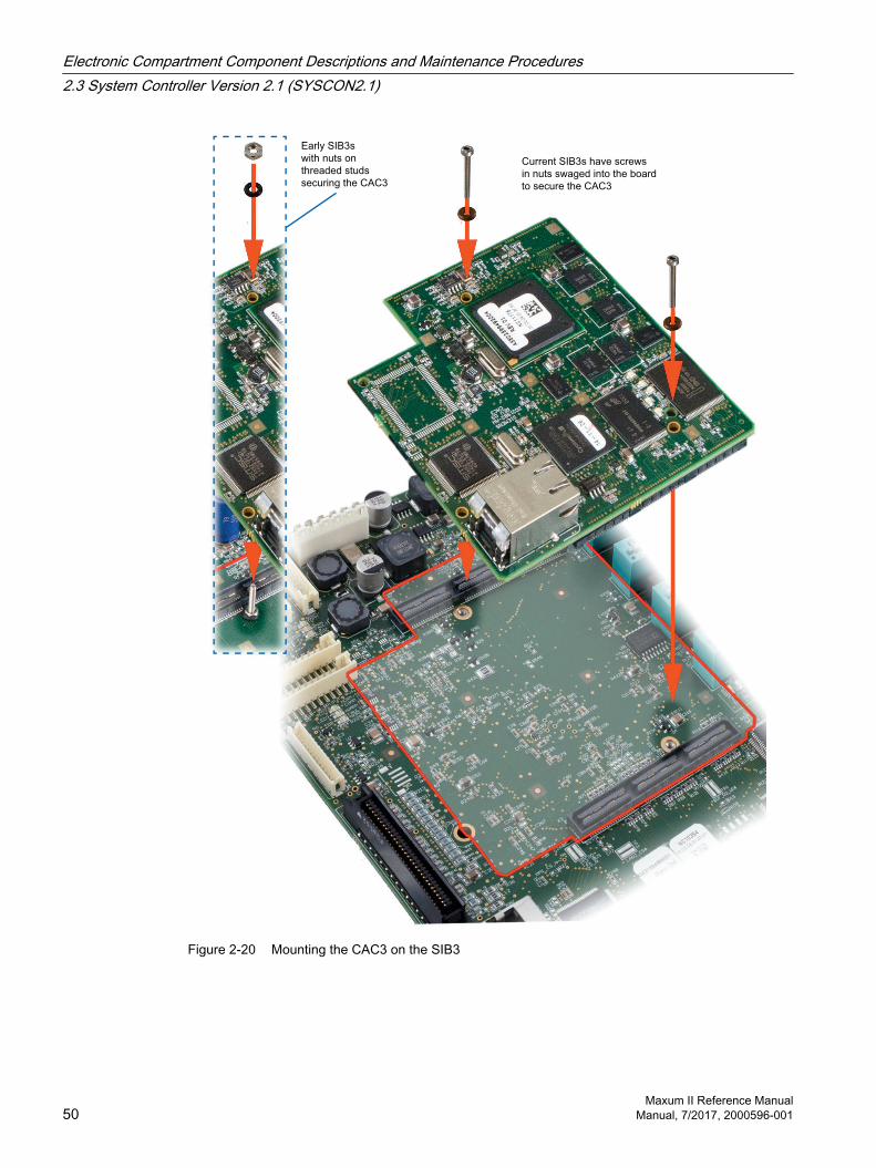
Early SIB3s
with nuts on
threaded studs
securing the CAC3
Current SIB3s have screws
in nuts swaged into the board
to secure the CAC3
Figure 2-20 Mounting the CAC3 on the SIB3
Electronic Compartment Component Descriptions and Maintenance Procedures2.3 System Controller Version 2.1 (SYSCON2.1)
Maxum II Reference Manual50 Manual, 7/2017, 2000596-001

Installing the CAC3 on the SIB3It will be neccessary to download the database saved earlier using GCP.
1. Carefully align the CAC3 connectors over the mating connectors of the SIB3.
2. Press down to fully engage the connectors.
3. Install the 2mm screws with o-rings. Avoid overtightening.
4. Plug in the ethernet cable.
5. Follow the steps in the General Analyzer Startup Procedure in the Maxum Edition II Analyzer General Maintenance Manual.
Removing a SIB31. As each cable is disconnected, move it clear of the SIB so it can be removed.
2. Make note of
– I/O board positions
– I/O cable location
– All cable positions to the SIB3
– SIB3 I/O Mode switch
3. Disconnect
– I/O cables from SIB3 and I/O boards
– Display cables
– Ethernet cable from CAC3
– Internal ethernet cable to SNEs if used
4. Remove ESB
5. Remove I/O boards
6. Disconnect from the SIB3
– I2C cables
– Purge cable
– Power cable
– Serial cables
– CAN bus cable if present
7. If the existing CAC3 will be reused, remove it following the procedure in the preceding section and place in a static-protected area.
Electronic Compartment Component Descriptions and Maintenance Procedures2.3 System Controller Version 2.1 (SYSCON2.1)
Maxum II Reference ManualManual, 7/2017, 2000596-001 51
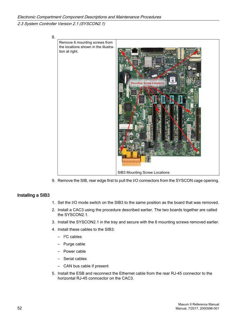
8.Remove 6 mounting screws from the locations shown in the illustra‐tion at right.
Mounting Screw Locations
SIB3 Mounting Screw Locations
9. Remove the SIB, rear edge first to pull the I/O connectors from the SYSCON cage opening.
Installing a SIB31. Set the I/O mode switch on the SIB3 to the same position as the board that was removed.
2. Install a CAC3 using the procedure described earlier. The two boards together are called the SYSCON2.1.
3. Install the SYSCON2.1 in the tray and secure with the 6 mounting screws removed earlier.
4. Install these cables to the SIB3:
– I2C cables
– Purge cable
– Power cable
– Serial cables
– CAN bus cable if present
5. Install the ESB and reconnect the Ethernet cable from the rear RJ-45 connector to the horizontal RJ-45 conncector on the CAC3.
Electronic Compartment Component Descriptions and Maintenance Procedures2.3 System Controller Version 2.1 (SYSCON2.1)
Maxum II Reference Manual52 Manual, 7/2017, 2000596-001

6. Install the I/O boards.
7. Reconnect these cables:
– I/O cables from SIB3 and I/O boards
– Display cables
– Ethernet cable from CAC3
– Internal ethernet cable to SNEs if used
2.3.6 Replacing the Lithium Battery on the SYSCON Module IntroductionOlder versions of the SYSCON module are equipped with a lithium battery for on‑board memory backup. For the original version SYSCON module this is a 3.6 V tube shaped battery. For the SYSCON2 module it is a 3.0 V flat battery. The latest version does not require a battery. If a lithium battery is present in your unit, Siemens recommends that the battery be replaced every 5 years. The battery should only be replaced with an approved spare. Contact Siemens for a replacement.
NOTICE
Observe battery polarity. Reversing the battery can damage the board.
Before removal of battery, note location of its positive end when installed in battery holder. The positive and negative terminals are marked on the battery. For the 3.6 V version (original SYSCON), note that the physical shape of the Positive and Negative terminals on the battery are NOT STANDARD.
2.3.7 ProcedureFollow this procedure to replace the battery.
1. Power down the analyzer using standard procedures.
2. Open electronic enclosure door (using a 4 mm (5/32 inch) Allen wrench if necessary). When door is open DO NOT place tension on the Maintenance Panel interface ribbon cable.
3. Using appropriate tools, loosen the topmost SYSCON Assembly fastening hardware that secures the assembly to electronic enclosure mounting bracket.
4. Pull the SYSCON drawer out and lower it so that it rests in the tilted-out position.
5. The battey holder is located on the left side of the SIB3 board. (Near the back on the original SYSCON board) Remove battery from its holder.
6. When installing the lithium battery in its holder, place the positive (+) side following the marking on the holder. Refer to the applicable picture in the previous step.Note that for the original SYSCON (3.6 V tube shaped battery) the physical shape of the positive and negative terminals on the battery are NOT like a standard battery.
7. After installation, push the SYSCON assembly back into its mounting facility and secure assembly in place with the fastening hardware.
Electronic Compartment Component Descriptions and Maintenance Procedures2.3 System Controller Version 2.1 (SYSCON2.1)
Maxum II Reference ManualManual, 7/2017, 2000596-001 53

8. Before closing door and reapplying AC power, be certain the battery is securely installed in its holder..
9. When the battery in a SYSCON is removed, current date and time information is lost. If the analyzer is configured to obtain date and time information from a central server, then it will update automatically. If no time server is set, it will be necessary to manually set the date and time on the analyzer.
2.4 Analog and Digital IO
How IO Channels Are UsedWhen low-power devices other than detectors are used either for measurements or control functions, IO channels can be used. These fall into four categories:
Digital Inputs allow the analyzer to detect whether some device is on or off. These can be either 'sinking' (Mode 2, the default configuration) or 'sourcing' (Mode1, used on legacy hardware and sometimes needed for a particular application). A switch on the SIB3 and on current IO boards selects between the two modes.
Digital Outputs are simply output relay channels that are either open or closed. These typically enable or disable a device, turn an indicator light on or off, or select a measurement range in a sensor.
Analog Inputs accept a variable voltage level and convert the level to a digital value that can be used in software.
Analog Outputs convert a digital value into a variable current that can be used to control some device or process.
SIB3-Based IOThe SYSCON2.1 has ten on-board inputs/outputs. The connectors for these are wired from two orange connectors on the front of the SYSCON assembly cage. Switch SW3 selects sink (Mode 2) or source (Mode 1) for the digital inputs.
IO Expansion BoardsThe IO expansion boards are plugged into the SIB3 backplane. The IO card circuitry is isolated from the connectors except for the 24v power connection on the CAN connector. The IO cards communicate with the SYSCON over the I2C cable assembly. Although this cable assembly also supplies 24v, the board is only powered from the CAN edge connector unless the IO board is being used outside of the backplane in a special configuration.
Electronic Compartment Component Descriptions and Maintenance Procedures2.4 Analog and Digital IO
Maxum II Reference Manual54 Manual, 7/2017, 2000596-001
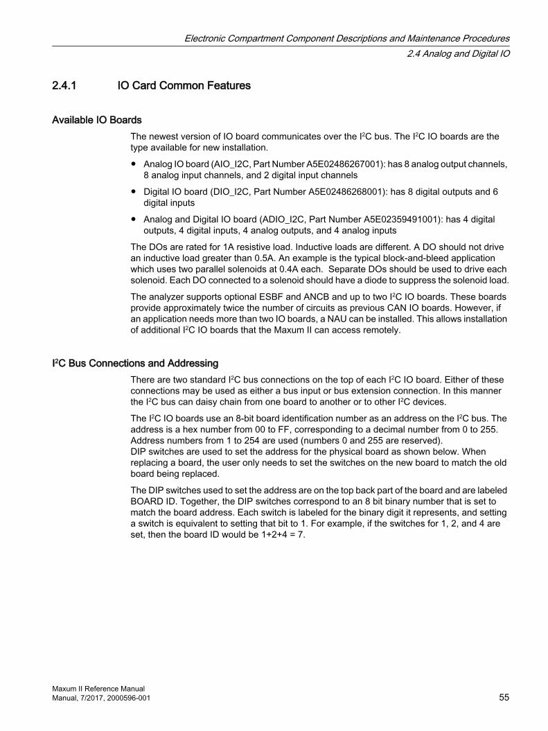
2.4.1 IO Card Common Features
Available IO BoardsThe newest version of IO board communicates over the I2C bus. The I2C IO boards are the type available for new installation.
Analog IO board (AIO_I2C, Part Number A5E02486267001): has 8 analog output channels, 8 analog input channels, and 2 digital input channels
Digital IO board (DIO_I2C, Part Number A5E02486268001): has 8 digital outputs and 6 digital inputs
Analog and Digital IO board (ADIO_I2C, Part Number A5E02359491001): has 4 digital outputs, 4 digital inputs, 4 analog outputs, and 4 analog inputs
The DOs are rated for 1A resistive load. Inductive loads are different. A DO should not drive an inductive load greater than 0.5A. An example is the typical block-and-bleed application which uses two parallel solenoids at 0.4A each. Separate DOs should be used to drive each solenoid. Each DO connected to a solenoid should have a diode to suppress the solenoid load.
The analyzer supports optional ESBF and ANCB and up to two I2C IO boards. These boards provide approximately twice the number of circuits as previous CAN IO boards. However, if an application needs more than two IO boards, a NAU can be installed. This allows installation of additional I2C IO boards that the Maxum II can access remotely.
I2C Bus Connections and AddressingThere are two standard I2C bus connections on the top of each I2C IO board. Either of these connections may be used as either a bus input or bus extension connection. In this manner the I2C bus can daisy chain from one board to another or to other I2C devices.
The I2C IO boards use an 8-bit board identification number as an address on the I2C bus. The address is a hex number from 00 to FF, corresponding to a decimal number from 0 to 255. Address numbers from 1 to 254 are used (numbers 0 and 255 are reserved).DIP switches are used to set the address for the physical board as shown below. When replacing a board, the user only needs to set the switches on the new board to match the old board being replaced.
The DIP switches used to set the address are on the top back part of the board and are labeled BOARD ID. Together, the DIP switches correspond to an 8 bit binary number that is set to match the board address. Each switch is labeled for the binary digit it represents, and setting a switch is equivalent to setting that bit to 1. For example, if the switches for 1, 2, and 4 are set, then the board ID would be 1+2+4 = 7.
Electronic Compartment Component Descriptions and Maintenance Procedures2.4 Analog and Digital IO
Maxum II Reference ManualManual, 7/2017, 2000596-001 55

I2C ID SwitchesLegacy position Default position
Figure 2-21 IO Board Switches
Electronic Compartment Component Descriptions and Maintenance Procedures2.4 Analog and Digital IO
Maxum II Reference Manual56 Manual, 7/2017, 2000596-001
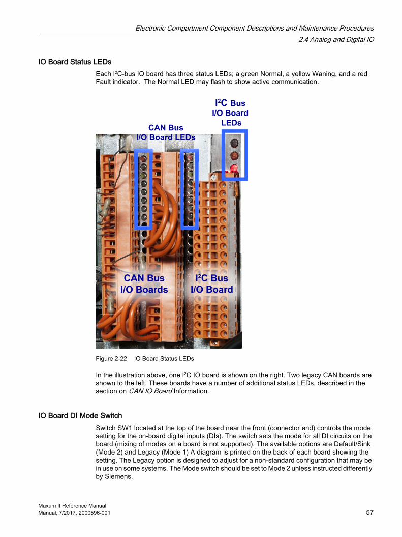
IO Board Status LEDsEach I2C-bus IO board has three status LEDs; a green Normal, a yellow Waning, and a red Fault indicator. The Normal LED may flash to show active communication.
CAN Bus
I/O Boards
I2C Bus
I/O Board
CAN Bus
I/O Board LEDs
I2C Bus
I/O Board
LEDs
Figure 2-22 IO Board Status LEDs
In the illustration above, one I2C IO board is shown on the right. Two legacy CAN boards are shown to the left. These boards have a number of additional status LEDs, described in the section on CAN IO Board Information.
IO Board DI Mode SwitchSwitch SW1 located at the top of the board near the front (connector end) controls the mode setting for the on-board digital inputs (DIs). The switch sets the mode for all DI circuits on the board (mixing of modes on a board is not supported). The available options are Default/Sink (Mode 2) and Legacy (Mode 1) A diagram is printed on the back of each board showing the setting. The Legacy option is designed to adjust for a non-standard configuration that may be in use on some systems. The Mode switch should be set to Mode 2 unless instructed differently by Siemens.
Electronic Compartment Component Descriptions and Maintenance Procedures2.4 Analog and Digital IO
Maxum II Reference ManualManual, 7/2017, 2000596-001 57
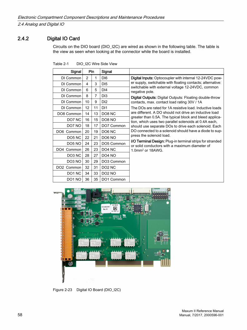
2.4.2 Digital IO CardCircuits on the DIO board (DIO_I2C) are wired as shown in the following table. The table is the view as seen when looking at the connector while the board is installed.
Table 2-1 DIO_I2C Wire Side View
Signal Pin Signal DI Common 2 1 DI6 Digital Inputs: Optocoupler with internal 12-24VDC pow‐
er supply, switchable with floating contacts; alternative: switchable with external voltage 12-24VDC, common negative pole.Digital Outputs: Digital Outputs: Floating double-throw contacts, max. contact load rating 30V / 1AThe DOs are rated for 1A resistive load. Inductive loads are different. A DO should not drive an inductive load greater than 0.5A. The typical block and bleed applica‐tion, which uses two parallel solenoids at 0.4A each, should use separate DOs to drive each solenoid. Each DO connected to a solenoid should have a diode to sup‐press the solenoid load.I/O Terminal Design: Plug-in terminal strips for stranded or solid conductors with a maximum diameter of 1.0mm2 or 18AWG.
DI Common 4 3 DI5DI Common 6 5 DI4DI Common 8 7 DI3DI Common 10 9 DI2DI Common 12 11 DI1
DO8 Common 14 13 DO8 NCDO7 NC 16 15 DO8 NODO7 NO 18 17 DO7 Common
DO6 Common 20 19 DO6 NCDO5 NC 22 21 DO6 NODO5 NO 24 23 DO5 Common
DO4 Common 26 23 DO4 NCDO3 NC 28 27 DO4 NODO3 NO 30 29 DO3 Common
DO2 Common 32 31 DO2 NCDO1 NC 34 33 DO2 NODO1 NO 36 35 DO1 Common
Figure 2-23 Digital IO Board (DIO_I2C)
Electronic Compartment Component Descriptions and Maintenance Procedures2.4 Analog and Digital IO
Maxum II Reference Manual58 Manual, 7/2017, 2000596-001

2.4.3 Analog IO BoardCircuits on the AIO board (AIO_I2C) are wired as shown in the following table. The table is the view as seen when looking at the connector while the board is installed.
Table 2-2 AIO_I2C Wire Side View
Signal Pin Signal AI8 -10V 2 1 AI8 +10V Analog Inputs: -20 to 20mA into 50Ω or -10 to 10V,
R10=1MΩ, mutually isolated 10VAnalog Outputs: 0-4 to 20mA. Common negative pole, galvanically separated from ground, freely con‐nectable to ground; working resistance 750Ω.Digital Inputs: Optocoupler with internal 12-24VDC power supply, switchable with floating contacts; alter‐native: switchable with external voltage 12-24VDC, common negative pole.I/O Terminal Design: Plug-in terminal strips for stran‐ded or solid conductors with a maximum diameter of 1.0mm2 or 18AWG.
AI7 -10V 4 3 AI7 +10VAI6 -10V 6 5 AI6 +10VAI5 -10V 8 7 AI5 +10VAI4 -10V 10 9 AI4 +10VAI3 -10V 12 11 AI3 +10VAI2 -10V 14 13 AI2 +10VAI1 -10V 16 15 AI1 +10V
AO_GND
18 17 AO8 Current20 19 AO7 Current22 21 AO6 Current24 23 AO5 Current26 23 AO4 Current28 27 AO3 Current30 29 AO2 Current32 31 AO1 Current
DI Common
34 33 DI236 35 DI1
Figure 2-24 Analog IO Board (AIO_I2C)
Electronic Compartment Component Descriptions and Maintenance Procedures2.4 Analog and Digital IO
Maxum II Reference ManualManual, 7/2017, 2000596-001 59

2.4.4 Analog and Digital IO BoardCircuits on the ADIO board are wired as shown in the following table. The table is the view as seen when looking at the connector while the board is installed.
Table 2-3 ADIO_I2C Wire Side View
Signal Pin Signal AI4 -10V 2 1 AI4 +10V Analog Inputs: -20 to 20mA into 50Ω or -10 to 10V, R10=1MΩ,
mutually isolated 10VAnalog Outputs: 0-4 to 20mA. Common negative pole, galvani‐cally separated from ground, freely connectable to ground; work‐ing resistance 750Ω.Digital Inputs: Optocoupler with internal 12-24VDC power supply, switchable with floating contacts; alternative: switchable with ex‐ternal voltage 12-24VDC, common negative pole.Digital Outputs: Digital Outputs: Floating double-throw contacts, max. contact load rating 30V / 1AI/O Terminal Design: Plug-in terminal strips for stranded or solid conductors with a maximum diameter of 1.0mm2 or 18AWG.
AI3 -10V 4 3 AI3 +10VAI2 -10V 6 5 AI2 +10VAI1 -10V 8 7 AI1 +10V
DI Common
10 9 DI412 11 DI314 13 DI216 15 DI1
AO_GND
18 17 AO4 Current20 19 AO3 Current22 21 AO2 Current24 23 AO1 Current
DO4 Common 26 23 DO4 NCDO3 NC 28 27 DO4 NODO3 NO 30 29 DO3 Common
DO2 Common 32 31 DO2 NCDO1 NC 34 33 DO2 NODO1 NO 36 35 DO1 Common
Figure 2-25 Analog and Digital I/O Board (ADIO_I2C)
Electronic Compartment Component Descriptions and Maintenance Procedures2.4 Analog and Digital IO
Maxum II Reference Manual60 Manual, 7/2017, 2000596-001

2.5 Detector Personality Modules
2.5.1 DPM TypesThree DPM types are used for temperature control and detector interface:
Intrinsically Safe Thermal Conductivity DPM
Base3DPM
Temperature Control Personality Module (TC-PM)
The interfaces available for each are shown in the table below.
Function TC-PM IS-TCD DPM Base3DPMTemperature control x xIntrinsic safety x
Detector inferfaces: RTD x Thermistor x Filament x FID x FPD x VPD x
2.5.2 Base3 Detector Personality Module (DPM)Output signals from any of the detectors connect to each associated Detector Personality Module (DPM) input. The transfer of detector data is based on the database method. The DPM digitizes the signal and then passes the data to the SYSCON via an I2C port. Results can then be viewed on the Color Touchscreen or the workstation.
The method is the part of the application that contains the parameters for controlling the hardware used by one cycle clock. It provides peak areas and component concentrations and includes all cycle clock timed events. There is one cycle clock per method.
Electronic Compartment Component Descriptions and Maintenance Procedures2.5 Detector Personality Modules
Maxum II Reference ManualManual, 7/2017, 2000596-001 61
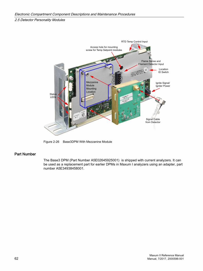
Status
LEDs
Access hole for mounting
screw for Temp Setpoint modules
Ignite Signal/
Igniter Power
Location
ID Switch
RTD Temp Control Input
Flame Sense and
Filament Detector Input
Signal Cable
from Detector
Mezzanine
Module
Mounting
Location
Figure 2-26 Base3DPM With Mezzanine Module
Part NumberThe Base3 DPM (Part Number A5E02645925001) is shipped with current analyzers. It can be used as a replacement part for earlier DPMs in Maxum I analyzers using an adapter, part number A5E34938458001.
Electronic Compartment Component Descriptions and Maintenance Procedures2.5 Detector Personality Modules
Maxum II Reference Manual62 Manual, 7/2017, 2000596-001
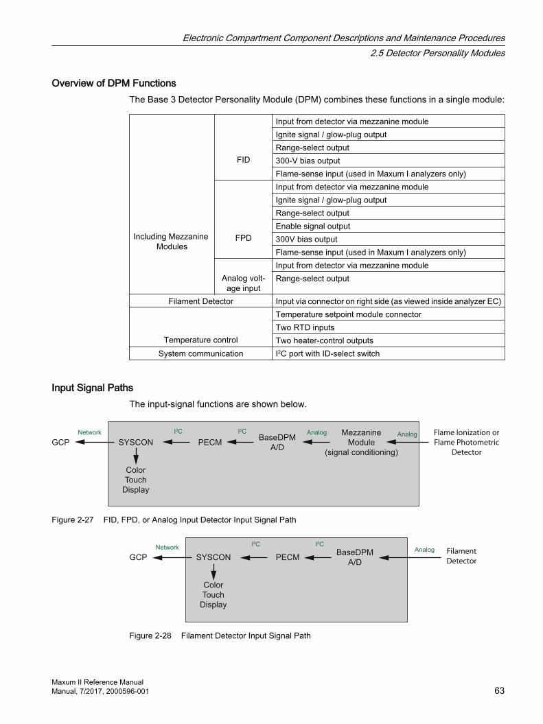
Overview of DPM FunctionsThe Base 3 Detector Personality Module (DPM) combines these functions in a single module:
Including Mezzanine Modules
FID
Input from detector via mezzanine moduleIgnite signal / glow-plug outputRange-select output300-V bias outputFlame-sense input (used in Maxum I analyzers only)
FPD
Input from detector via mezzanine moduleIgnite signal / glow-plug outputRange-select outputEnable signal output300V bias outputFlame-sense input (used in Maxum I analyzers only)
Analog volt‐
age input
Input from detector via mezzanine moduleRange-select output
Filament Detector Input via connector on right side (as viewed inside analyzer EC)
Temperature control
Temperature setpoint module connectorTwo RTD inputsTwo heater-control outputs
System communication I2C port with ID-select switch
Input Signal PathsThe input-signal functions are shown below.
Analog Flame Ionization or
Flame Photometric
Detector
Network I2C I2C Analog
GCP
Color
Touch
Display
SYSCON PECMBaseDPM
A/D
Mezzanine
Module
(signal conditioning)
Figure 2-27 FID, FPD, or Analog Input Detector Input Signal Path
NetworkI2C I2C
Analog
GCP
Color
Touch
Display
SYSCON PECMBaseDPM
A/D
Filament
Detector
Figure 2-28 Filament Detector Input Signal Path
Electronic Compartment Component Descriptions and Maintenance Procedures2.5 Detector Personality Modules
Maxum II Reference ManualManual, 7/2017, 2000596-001 63

Detector Control PathsSeveral control signals are available to control various detector functions as shown below.
5 V Power (FPD)
Enable (FPD)
300 V Bias (FID)
Digital (Ignite) / Power (Glow Plug)
Network I2C I2C
Digital
(Range
Select)
GCP
Color
Touch
Display
SYSCON PECMBaseDPM
A/D
Mezzanine
Module
(signal conditioning)
FID
FPD
Analog
Output
Figure 2-29 Maxum II Detector Control Functions
Location ID SwitchThe Location ID Switch, shown previously in the photograph, selects the DPM location that is incorporated in the address, to be reported in the results.
The DPM I2C port is connected directly to the system controller via the PECM or a wiring distribution board. In this scenario, the following values are applied:
Switch Value Location1 Left2 Center3 Right
NOTE:If the DPM I2C port is connected to an SNE, the value is always set to “1”. The actual location value is determined by the SNE.
Electronic Compartment Component Descriptions and Maintenance Procedures2.5 Detector Personality Modules
Maxum II Reference Manual64 Manual, 7/2017, 2000596-001

DPM-Based Temperature ControlThe Base3 DPM has two temperature-control channels. Two RTD inputs feed two comparator circuits to drive two heater-control outputs. The heater-control outputs connect to inputs on the PECM in most analyzers. The control path is shown below.
SY
SC
ON
DPM
SSRbSSRa
AC
Line Heater
Airflow Loss
Shutdown
Temperature
Control
I2CPWM
Temp
Setpoint
Modules
Temp Control,
Temp Limit,
Overtemp RTDs
Digital Air Pressure
Switch
SSR Pair
Analog
High-Wattage
Heater
Air Bath Oven
PECM
Airflow
Loss
Shutdown
Compare
Figure 2-30 Heater Control Path Using DPM
A mounting location and connector are provided for two Temperature Setpoint Modules. The modules are installed on the left side (back) of the DPM, shown below. This same position is used in the Temperature Control DPM.
RTD Temp Control Inputs
I2C
He
ate
r C
on
tro
l O
utp
uts
to
PE
CM
Lo
ca
tio
n ID
Sw
itch
Temp Setpoint Module
Mounting Screw Access
Temp Setpoint Module
Mounting Location
Status
LEDs
Figure 2-31 Temperature Setpoint Modules Installed on Left Side of Base3 DPM
Electronic Compartment Component Descriptions and Maintenance Procedures2.5 Detector Personality Modules
Maxum II Reference ManualManual, 7/2017, 2000596-001 65

Mezzanine ModulesA mezzanine module conditions the signal from a non-conductivity detector. The mezzanine plugs into the Base3 DPM in order to tailor the DPM for a specific measurement.
Three primary types of mezzanine are available to accommodate FID and FPD detectors, and various detectors that produce a scaled analog output (AI) mezzanine. Some of the mezzanines have a dual range function for maximum flexibility. See the table below for details relating to the various mezzanine options.
The AI mezzanine can be used for reading a detector voltage signal from a specialized or third party detector, such as the Valco PDD, where the device only supplies a scaled voltage output. The AI signal will be treated like a normal detector signal, with a 50% balance range.
Table 2-4 Mezzanine Part Number Descriptions
Mezzanine Detector Sub Module Type
Usage Normal Range
Alternate Range
2020960-001 FID Low level FID 0.2nA none2020960-003 Standard FID 1nA 20nA2021328-002 Large Scale FID 100nA 1000nA2021328-001 FPD FPD 100nA none2021328-003 FPD, 0.18 Hz Filter 100nA none2021326-001 Universal Voltage AI ±1V ±10V1901614-001 Dummy Plug
When Base DPM is Filament only, and no mezzanine required
none none
2.5.3 Replacing a Base3DPM
Removing the Base3DPMSee the illustration Base3 DPM With Mezzanine Module and Temperature Setpoint Modules Installed on Left Side of Base3DPM for connector and module locations.
1. Back up and shut down the unit using the General Analyzer Shutdown Procedure.
2. Open the electronics enclosure door.
3. Disconnect the detector signal cable from the mezzanine module.
– FID and FPD mezzanine modules use SMA coaxial cables. Unscrew the nut to unplug the cable.
– Analog input mezzanine modules use small terminal block connectors that can be unplugged.
4. Disconnect the fIlament detector cable if present.
5. Disconnect the RTD temperature input cables (top rear of unit, if present).
6. If present, take out screws holding the IS ground cables (typically only installed on modular oven models).
7. Remove the nut on the bottom-front of DPM bracket.
Electronic Compartment Component Descriptions and Maintenance Procedures2.5 Detector Personality Modules
Maxum II Reference Manual66 Manual, 7/2017, 2000596-001

8. Slide the unit forward to disengage the rear mounting lug.
9. Lift the unit up and part way out of the enclosure.
10.Disconnect the I2C/power cable and temperature control output cables from the rear edge of the board.
11.Remove the unit from the analyzer and place on ESD-safe work surface.
12.Unscrew the two mounting screws at the top corners of the mezzanine module, and unplug it from the Base3 DPM.
13.Unscrew the mounting screw for the temperature setpoint module stack using the access hole in the metal plate near the filament detector input.
14.Unplug the temperature setpoint module stack from the left side of the board.
15.Remove the two mounting screws near the upper corners and remove the old board from the cage.
Configuring the New Base3DPMSet the location ID switch on the replacement unit to match the unit being removed.
Installing the Replacement Base3DPM1. Install the new unit into the DPM cage. Insert the bottom edge into the slot in the plastic
DPM mounting rail on the DPM cage, and secure with the two screws removed from the old unit.
2. Plug the temperature setpoint module stack onto its mount on the left side of the unit.
3. Reinstall the screw to secure the temperature setpoint module stack through the access hole on the right side of the unit.
4. Plug the mezzanine module onto its connector on the right side of the unit, and reinstall the two screws ear the top edge.
5. Insert the rear lug into the slot at the rear of the DPM mounting position with the mounting stud at the front inserted through the slot in the DPM bracket.
6. Slide backward to lock the rear mounting lug into the slot.
7. Reinstall the nut on the threaded stud to secure the DPM.
8. Reconnect the I2C/power cable and temperature control output cables from the rear edge of the board.
9. Reconnect the RTD temperature input cables (top rear of unit, if present).
10.Reconnect the fIlament detector cable if present.
11.Reconnect the detector signal cable from the mezzanine module.
12.Follow the steps in the General Analyzer Startup Procedure.
Electronic Compartment Component Descriptions and Maintenance Procedures2.5 Detector Personality Modules
Maxum II Reference ManualManual, 7/2017, 2000596-001 67
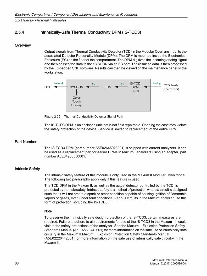
2.5.4 Intrinsically-Safe Thermal Conductivity DPM (IS-TCD3)
OverviewOutput signals from Thermal Conductivity Detector (TCD) in the Modular Oven are input to the associated Detector Personality Module (DPM). The DPM is mounted inside the Electronics Enclosure (EC) on the floor of the compartment. The DPM digitizes the incoming analog signal and then passes the data to the SYSCON via an I2C port. The resulting data is then processed by the Embedded SNE software. Results can then be viewed on the maintenance panel or the workstation.
TCD Beads
(thermistor)
IS-TCD
DPM
(A/D)
PECMSYSCON
Color
Touch
Display
GCP
AnalogI2CI2CNetwork
Figure 2-32 Thermal Conductivity Detector Signal Path
The IS-TCD3 DPM is an enclosed unit that is not field repairable. Opening the case may violate the safety protection of the device. Service is limited to replacement of the entire DPM.
Part NumberThe IS-TCD3 DPM (part number A5E02645923001) is shipped with current analyzers. It can be used as a replacement part for earlier DPMs in Maxum I analyzers using an adapter, part number A5E34938550001.
Intrinsic SafetyThe intrinsic safety feature of this module is only used in the Maxum II Modular Oven model. The following two paragraphs apply only if this feature is used.
The TCD DPM in the Maxum II, as well as the actual detector controlled by the TCD, is protected by intrinsic safety. Intrinsic safety is a method of protection where a circuit is designed such that it will not create a spark or other condition capable of causing ignition of flammable vapors or gases, even under fault conditions. Various circuits in the Maxum analyzer use this form of protection, including the IS-TCD3.
Note
To preserve the intrinsically safe design protection of the IS-TCD3, certain measures are required. Failure to adhere to all requirements for use of the IS-TCD3 in the Maxum II could violate the safety protections of the analyzer. See the Maxum II Explosion Protection Safety Standards Manual (A5E02220442001) for more information on the safe use of intrinsically safe circuitry in the Maxum II.Maxum II Explosion Protection Safety Standards Manual (A5E02220442001) for more information on the safe use of intrinsically safe circuitry in the Maxum II.
Electronic Compartment Component Descriptions and Maintenance Procedures2.5 Detector Personality Modules
Maxum II Reference Manual68 Manual, 7/2017, 2000596-001
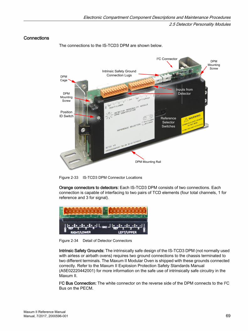
ConnectionsThe connections to the IS-TCD3 DPM are shown below.
DPM
Mounting
Screw
DPM Mounting Rail
DPM
Mounting
Screw
DPM
Cage
Reference
Selector
Switches
I2C Connector
Intrinsic Safety Ground
Connection Lugs
Position
ID Switch
Inputs from
Detector
Figure 2-33 IS-TCD3 DPM Connector Locations
Orange connectors to detectors: Each IS-TCD3 DPM consists of two connections. Each connection is capable of interfacing to two pairs of TCD elements (four total channels, 1 for reference and 3 for signal).
Figure 2-34 Detail of Detector Connectors
Intrinsic Safety Grounds: The intrinsically safe design of the IS-TCD3 DPM (not normally used with airless or airbath ovens) requires two ground connections to the chassis terminated to two different terminals. The Maxum II Modular Oven is shipped with these grounds connected correctly. Refer to the Maxum II Explosion Protection Safety Standards Manual (A5E02220442001) for more information on the safe use of intrinsically safe circuitry in the Maxum II.
I2C Bus Connection: The white connector on the reverse side of the DPM connects to the I2C Bus on the PECM.
Electronic Compartment Component Descriptions and Maintenance Procedures2.5 Detector Personality Modules
Maxum II Reference ManualManual, 7/2017, 2000596-001 69

Reference
Selector
Switches:
Selects
reference
channel
Position ID Switch:
1 = Left
2 = Center
3 = Right
(Described in
Location ID Switch)
Figure 2-35 IS-TCD3 DPM Switches
Figure 2-36 TCD Information Path (Airless and Airbath models)
2.5.5 Replacing an IS-TCD DPM
Removing the IS-TCD3 DPMSee the illustration IS-TCD3 DPM Connector Locations (Page 69) for connector locations.
1. Back up and shut down the unit using the General Analyzer Shutdown Procedure in the Maxum Edition II Analyzer General Maintenance Manual.
2. Open the electronics enclosure door.
3. Disconnect the detector cables by unplugging the orange connectors.
4. Disconnect the I2C/power cable.
5. If present, take out screws holding the IS ground cables (typically only installed on modular oven models).
6. Remove the nut on the bottom-front of DPM bracket.
7. Slide the unit forward to disengage the rear mounting lug.
Electronic Compartment Component Descriptions and Maintenance Procedures2.5 Detector Personality Modules
Maxum II Reference Manual70 Manual, 7/2017, 2000596-001

8. Lift the unit up and out of the enclosure and place on an ESD-safe work surface.
9. Remove the two mounting screws near the upper corners and remove the old unit from the DPM cage.
Configuring the New IS-TCD3 DPMSet the location ID switch and reference-selector switches on the replacement unit to match those on the unit being removed.
Note
The newer units use slide switches in place of the 2-position rotary switches on older units. The function is the same.
Installing the Replacement IS-TCD3 DPM1. Install the new unit into the DPM cage. Insert the bottom edge into the slot in the plastic
DPM mounting rail on the DPM cage, and secure with the two screws removed from the old unit.
2. Insert the rear lug into the slot at the rear of the DPM mounting position with the mounting stud at the front inserted through the slot in the DPM bracket.
3. Slide backward to lock the rear mounting lug into the slot.
4. Reinstall the nut on the threaded stud to secure the DPM.
5. Reconnect the I2C/power cable.
6. Reconnect the IS ground cables if used.
7. Reconnect the detector cables.
8. Follow the steps in the General Analyzer Startup Procedure in the Maxum Edition II Analyzer General Maintenance Manual.
See alsoIntrinsically-Safe Thermal Conductivity DPM (IS-TCD3) (Page 68)
2.5.6 Replacing a TC-DPM
Removing the TC-DPMSee the illustration Temperature Control Personality Module Connections for connector and module locations.
1. Back up and shut down the unit using the General Analyzer Shutdown Procedure.
2. Open the electronics enclosure door.
3. Disconnect the RTD temperature input cables (top rear of unit, if present).
Electronic Compartment Component Descriptions and Maintenance Procedures2.5 Detector Personality Modules
Maxum II Reference ManualManual, 7/2017, 2000596-001 71

4. Remove the nut on the bottom-front of DPM bracket.
5. Slide the unit forward to disengage the rear mounting lug.
6. Lift the unit up and part way out of the enclosure.
7. Disconnect the I2C/power cable and temperature control output cables from the rear edge of the board.
8. Remove the unit from the analyzer and place on ESD-safe work surface.
9. Unscrew the mounting screw for the temperature setpoint module stack using the access hole near the center of the metal plate.
10.Unplug the temperature setpoint module stack from the left side of the board.
11.Remove the two mounting screws near the upper corners and remove the old unit from the cage.
Configuring the New TC-DPMSet the location ID switch on the replacement unit to match the unit being removed.
Installing the Replacement TC-DPM1. Install the new unit into the DPM cage. Insert the bottom edge into the slot in the plastic
DPM mounting rail on the DPM cage, and secure with the two screws removed from the old unit.
2. Plug the temperature setpoint module stack onto its mount on the left side of the unit.
3. Reinstall the screw to secure the temperature setpoint module stack through the access hole on the right side of the unit.
4. Insert the rear lug into the slot at the rear of the DPM mounting position with the mounting stud at the front inserted through the slot in the DPM bracket.
5. Slide backward to lock the rear mounting lug into the slot.
6. Reinstall the nut on the threaded stud to secure the DPM.
7. Reconnect the I2C/power cable and temperature control output cables from the rear edge of the board.
8. Reconnect the RTD temperature input cables (top rear of unit, if present).
9. Follow the steps in the General Analyzer Startup Procedure.
2.6 Sensor Near Electronics (SNE) SoftwareThe Sensor Near Electronics (SNE) is a software module that provides Maxum II Gas Chromatograph physics control, data analysis and data reduction. This virtual SNE operates as a set of intercommunicating tasks running on the pSOS+ operating system. These functions run on the SYSCON2.1 hardware in recent Maxum II analyzers. In older analyzers, these functions run on processors mounted in the SNE cage along with the DPMs.
Electronic Compartment Component Descriptions and Maintenance Procedures2.6 Sensor Near Electronics (SNE) Software
Maxum II Reference Manual72 Manual, 7/2017, 2000596-001

ConfigurationThe SNE is configured by the System Controller (SYSCON) and periodically reports analysis results. It can be interactively controlled for Real-Time decisions on operation scenarios. The SNE software controls all sampling relating to its internal configuration and sensor setup.
ComponentsThe major SNE software components are as follows:
Data Manager Communications Manager
Hardware Manager Computational Engine
Data ManagerThe Data Manager maintains configuration data that controls hardware sequence of events and controls what manipulation is performed on sampled data.
The Data Manager also provides results and status information to externally connected devices via the Communication Manager. This data is organized as a set of Sensor Analyzer Module (SAM) structures. The data represents the unit as a standard sensor to external host.
Communication ManagerThe Communication Manager acts as a central point of control for communication links attached to the Sensor Near Electronics (SNE). This allows Internal SNE software to function regardless of which communication link is being used to communicate with the system.
Hardware ManagerThe Hardware Manager provides scheduling and communication services for the hardware in the analysis zone. These include devices such as the following:
Detectors Sample valves Relays
Pressure monitors and controllers Temperature monitors and controllers Flow control valves
Computational EngineThe Computational Engine takes acquired chromatography data and performs system calculations. Most of these calculations are performed by functions contained in the EZChrom method, which provides all peak identifications and integration and response factors.
Electronic Compartment Component Descriptions and Maintenance Procedures2.6 Sensor Near Electronics (SNE) Software
Maxum II Reference ManualManual, 7/2017, 2000596-001 73

2.7 Solid State Relay ModuleThe Solid State Relay (SSR) Module is made up of two pairs of high wattage heater relays that are used for controlling the oven air bath heaters. One pair controls ABH1 and the other ABH2. Each pair of relays controls Temperature Limit and Oven Temperature shut down. If the over temperature limit is exceeded, the power to the air bath heater is shutdown. Two different configurations of SSR are available, the SSR and the Medium Wattage SSR. There are also original and new versions of the standard SSR.
New SSROriginal SSR Medium Wattage SSR
Figure 2-37 Solid State Relay Modules
The SSR module assembly is mounted to the left side of the EC back wall. A metal cover not shown in the photograph above protects the relays for the standard version of the SSR. The standard version of the SSR is equipped with heat dissipating fins that extend through the back of the enclosure wall to dissipate generated heat to the outside atmosphere. The medium wattage version dissipates heat to the interior of the electronics enclosure using heat sinks.
The standard SSR, also called high wattage, can provide switching for two heater elements of up to 1400 watts each. The medium wattage version can control two heater elements of up to 500 watts each. Relays for both the original and new standard SSR versions are available as spare parts. For the medium wattage SSR, individual relays cannot be replaced.
NOTICE
The SSR module supports either 115 VAC or 230 VAC power. For 115 VAC power the in-line fuses to the SSR should be rated at 16 A. For 230 VAC, the fuses must be rated at 10 A. DO NOT use a 16 A rated fuse for 230 VAC primary AC power. This could result in overheating and equipment damage.
High Wattage SSRThe relays on the newer SSR provide an indicator LED which shows the operational status of the control signals. In addition the newer SSR is equipped with a plastic shield which covers the connection screw terminals and helps prevent inadvertent contact. Note, however, that the older SSR is entirely enclosed in a sheet metal housing so human contact is not possible without disassembly of the module.
Electronic Compartment Component Descriptions and Maintenance Procedures2.7 Solid State Relay Module
Maxum II Reference Manual74 Manual, 7/2017, 2000596-001

The PECM provides the voltage to the two pairs of 1400-Watt AC Air Bath heater power switching circuits located on the rear wall of the electronic enclosure. A dedicated cable connects the PECM to the relay assembly. Each circuit has two solid-state relays connected in series.
One series-connected relay controls the 1400-Watt AC heater functions to maintain controller initiated set point temperature. In conjunction with the control signal, the air bath heater pressure switch enables the relay. The second series-connected relay is used for safety purposes. It performs an emergency analyzer system shutdown if an over-temperature condition is detected. Both relay circuits are completely independent of each other. However, in order for the power switching to occur both relays must be enabled. Temperature controls are monitored on the Detector Personality Module located in the SNE and routed to the PECM via a dedicated cable. No other functions are connected to the temperature control circuit.
3412
3412
Schematic A
4
3
2
1
orACLine
Load
Load
Sn
ub
be
rZerovoltagedetect
LED
Rc
ControlVoltage
Figure 2-38 Air Bath Heater Relay Schematic
Medium Wattage SSRA medium wattage version of the Solid State Relay (SSR) module is available. The original assembly included four large relays suitable for switching two of the 1400 watt air bath oven heater elements. However, many Maxum GCs do not require that much power. Therefore, a new SSR Module was added to the Maxum spare part offering. The newer board provides smaller relays which are capable of controlling the new 500 watt air bath heater assembly described previously. In addition, the “medium power” SSRB can be used to control the two 250 watt heaters used in the Maxum airless oven configurations. The newer board can also be used to control the low wattage heaters in the heated Flame Ionization and Flame Photometric detector housings or in heated sample injection valves.
The relays on the medium wattage SSR cannot be replaced individually. However, the module is easily replaced. Another difference between the high wattage SSR and medium wattage SSR is that the medium wattage version does not required heat dissipating fins on the back of the enclosure. The relays are equipped with heat sinks on the front of the module as shown in the photograph below.
Electronic Compartment Component Descriptions and Maintenance Procedures2.7 Solid State Relay Module
Maxum II Reference ManualManual, 7/2017, 2000596-001 75

Power Cable
from PECM
Control Cable from
PECM or DPM
Status LEDsStatus LEDs
Figure 2-39 Medium Wattage SSR Module
2.8 Solenoid Valves
2.8.1 Solenoid Valve Control Module (SVCM)The Solenoid Valve Control Module (SVCM) provides pneumatic interface to control flow to the oven sampling and column valves. Solenoid valves are suitable for air, nitrogen and helium on the pressure side and vacuum on the vent side. The electronic enclosure has space for up to three modules.
SVCM VersionsThere are two configurations of SVCM. The old version, which is still supported as a spare part, is equipped with a valve driver circuit board. For the newer version of the SVCM, this valve drive circuitry has been moved to the PECM2 module. The newer version has a lower cost and is more reliable and robust.
The SVCM electronics, whether onboard for the old version or on the PECM for the new version, receives commands from the SYSCON module (via the I2C bus). Pulse timing is controlled from the SVCM electronics.
Electronic Compartment Component Descriptions and Maintenance Procedures2.8 Solenoid Valves
Maxum II Reference Manual76 Manual, 7/2017, 2000596-001
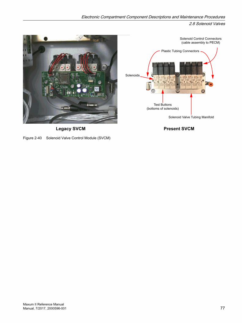
Solenoids
Solenoid Control Connectors
(cable assembly to PECM)
Plastic Tubing Connectors
Test Buttons
(bottoms of solenoids)
Solenoid Valve Tubing Manifold
Legacy SVCM Present SVCM
Figure 2-40 Solenoid Valve Control Module (SVCM)
Electronic Compartment Component Descriptions and Maintenance Procedures2.8 Solenoid Valves
Maxum II Reference ManualManual, 7/2017, 2000596-001 77
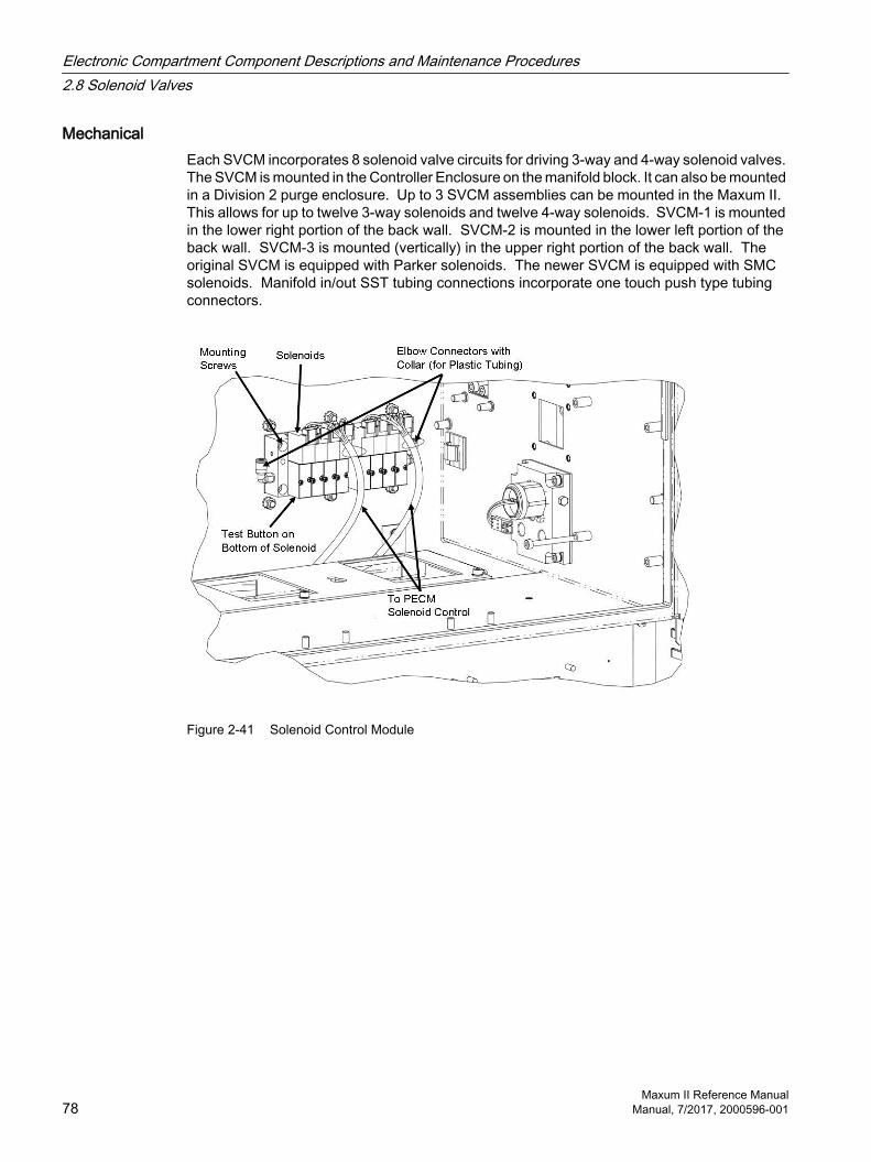
MechanicalEach SVCM incorporates 8 solenoid valve circuits for driving 3-way and 4-way solenoid valves. The SVCM is mounted in the Controller Enclosure on the manifold block. It can also be mounted in a Division 2 purge enclosure. Up to 3 SVCM assemblies can be mounted in the Maxum II. This allows for up to twelve 3-way solenoids and twelve 4-way solenoids. SVCM-1 is mounted in the lower right portion of the back wall. SVCM-2 is mounted in the lower left portion of the back wall. SVCM-3 is mounted (vertically) in the upper right portion of the back wall. The original SVCM is equipped with Parker solenoids. The newer SVCM is equipped with SMC solenoids. Manifold in/out SST tubing connections incorporate one touch push type tubing connectors.
Figure 2-41 Solenoid Control Module
Electronic Compartment Component Descriptions and Maintenance Procedures2.8 Solenoid Valves
Maxum II Reference Manual78 Manual, 7/2017, 2000596-001

Digital Control ChannelsOn present Maxum II analyzers, the solenoid control circuitry is on the PECM. Digital outputs assigned to each solenoid valve are shown in the table below. If a digital output is 0 the valve is OFF; if the output is a 1, the valve is ON. Each group of four valves is identified as being left or right. There are no digital inputs. See the table below for the numbering pattern of solenoid valves (same for original and newer versions). Each solenoid valve can be manually set to the ON or OFF conditions by manually depressing the red button on each solenoid. This button is on the top-front of each Parker (original) solenoid and on the bottom of each SMC (new) solenoid.
Table 2-5 Digital Output Solenoid Valve Groups
Group Solenoid ValveLeft Valve 1
Valve 2Valve 3Valve 4
Right Valve 1Valve 2Valve 3Valve 4
Table 2-6 SVCM I/O Assignments
SYSCON Channel Number
I/O Name Group Channel
DO1 LEFT_GROUP_VALVE_1 1
80hDO 2 LEFT_GROUP_VALVE_2 40hDO 3 LEFT_GROUP_VALVE_3 20hDO 4 LEFT_GROUP_VALVE_4 10hDO 5 RIGHT_GROUP_VALVE_1 08hDO 6 RIGHT_GROUP_VALVE_2 04hDO 7 RIGHT_GROUP_VALVE_3 02hDO 8 RIGHT_GROUP_VALVE_4 01h
Table 2-7 SVCM Fault Indicators
Fault Indicator Fault ConditionVALVE_SWITCH_ERROR Valve status read back is incorrectJ10_DISCONNECTED (left bank connector) J10 connector not connectedJ11_DISCONNECTED (right bank connector) J11 connector not connected
Electronic Compartment Component Descriptions and Maintenance Procedures2.8 Solenoid Valves
Maxum II Reference ManualManual, 7/2017, 2000596-001 79

Table 2-8 Specifications
Function SpecificationSwitching Speed (Maximum response time on/off ms) 4-way 15ms 3-way non-latching 15msOperating Voltage 24VDCPressure Range, 3-way 25 to 100psiPressure Range, 4-way 25 to 100psiVacuum Range 0 to 27" of HgAmbient Temperature Range -18°C to 65°C
-0.4°F to 149°F (dry air)Leakage ≤ 50 microLiter/min, air @ 69.8?F (21°C) with 50psig on the
common port.
Operation Test1. Using a fine-pointed object, press Solenoid Valve red button.
2. When pressed, pressure is applied to the piston that moves to either the open or closed position. Resulting pressure is then applied to the column or sample valve.
3. If piston does not operate when the button is pressed, check for correct gas pressure.
4. If piston does not operate and pressure is 75 psig, Solenoid Valve is defective and must be replaced.
5. Repeat for each valve operating on and off. Allow at least 1 second between button presses.
2.8.2 Replacing a Solenoid ValveThe solenoid valves are mounted on either the floor or back of the electronic enclosure, depending on configuration. Valves are replaced individually. The Solenoid Valve Replacement Kit is available as part number 2020149-001.
WARNING
Voltage dangerous to life exists. Failure to follow proper procedures may result in equipment damage, personal injury or death.
Before performing the removal and installation procedures, turn off primary AC power to the Maxum II from the main circuit breaker. Observe all site safety requirements before performing any repair or maintenance on the Maxum II.
Electronic Compartment Component Descriptions and Maintenance Procedures2.8 Solenoid Valves
Maxum II Reference Manual80 Manual, 7/2017, 2000596-001
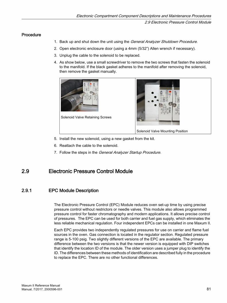
Procedure1. Back up and shut down the unit using the General Analyzer Shutdown Procedure.
2. Open electronic enclosure door (using a 4mm (5/32”) Allen wrench if necessary).
3. Unplug the cable to the solenoid to be replaced.
4. As show below, use a small screwdriver to remove the two screws that fasten the solenoid to the manifold. If the black gasket adheres to the manifold after removing the solenoid, then remove the gasket manually.
Solenoid Valve Retaining Screws
Solenoid Valve Mounting Position
5. Install the new solenoid, using a new gasket from the kit.
6. Reattach the cable to the solenoid.
7. Follow the steps in the General Analyzer Startup Procedure.
2.9 Electronic Pressure Control Module
2.9.1 EPC Module Description
The Electronic Pressure Control (EPC) Module reduces oven set-up time by using precise pressure control without restrictors or needle valves. This module also allows programmed pressure control for faster chromatography and modern applications. It allows precise control of pressures. The EPC can be used for both carrier and fuel gas supply, which eliminates the less reliable mechanical regulation. Four independent EPCs can be installed in one Maxum II.
Each EPC provides two independently regulated pressures for use on carrier and flame fuel sources in the oven. Gas connection is located in the regulator section. Regulated pressure range is 5-100 psig. Two slightly different versions of the EPC are available. The primary difference between the two versions is that the newer version is equipped with DIP switches that identify the location ID of the module. The older version uses a jumper plug to identify the ID. The differences between these methods of identification are described fully in the procedure to replace the EPC. There are no other functional differences.
Electronic Compartment Component Descriptions and Maintenance Procedures2.9 Electronic Pressure Control Module
Maxum II Reference ManualManual, 7/2017, 2000596-001 81
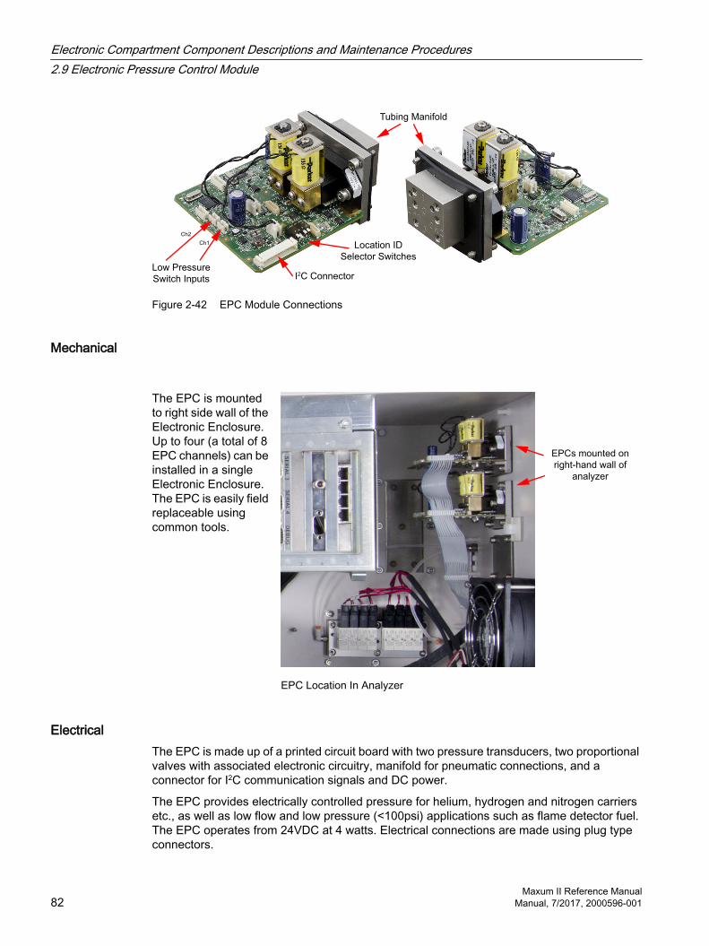
Ch2
Ch1
Low Pressure
Switch Inputs
Location ID
Selector Switches
I2C Connector
Tubing Manifold
Figure 2-42 EPC Module Connections
Mechanical
The EPC is mounted to right side wall of the Electronic Enclosure. Up to four (a total of 8 EPC channels) can be installed in a single Electronic Enclosure. The EPC is easily field replaceable using common tools.
EPCs mounted on
right-hand wall of
analyzer
EPC Location In Analyzer
ElectricalThe EPC is made up of a printed circuit board with two pressure transducers, two proportional valves with associated electronic circuitry, manifold for pneumatic connections, and a connector for I2C communication signals and DC power.
The EPC provides electrically controlled pressure for helium, hydrogen and nitrogen carriers etc., as well as low flow and low pressure (<100psi) applications such as flame detector fuel. The EPC operates from 24VDC at 4 watts. Electrical connections are made using plug type connectors.
Electronic Compartment Component Descriptions and Maintenance Procedures2.9 Electronic Pressure Control Module
Maxum II Reference Manual82 Manual, 7/2017, 2000596-001
The EPC receives commands from the SYSCON via I2C bus regarding timing and pressure setpoint. The timing of messages from the SYSCON controls timing within the EPC. There is no time base in the EPC. Module control is established by sending parameters, such as setpoint pressures and ramp rates to the EPC. The EPC is used in the Maxum II to control the carriers and/or fuels for the detector modules. The EPC can also be used in field-mounted installations.
The EPC communicates with other components via the I2C bus and communicates actual pressure back to the SYSCON. Regulated pressure range is 5-100psig.
ChannelsEach EPC channel consists of a pressure sensor amplifier and analog filter followed by an A/D Converter. The converter is read by the local controller that calculates a new control value used to control the proportional solenoid valve.
Control parameters, such as set-point pressures are sent via the I2C bus to the EPC. Status and diagnostic data is available via software.
DiagnosticsEPC diagnostics are read-back of setpoint pressure via the software, DC power within operating limits, monitoring of line and short-term pressure variations with respect to the setpoint regulation, out of range pressure alarm and a diagnostic failure.
2.9.2 Replacing an EPC Module
WARNING
Voltage dangerous to life exists. Failure to follow proper procedures may result in equipment damage, personal injury or death.
Before performing the removal and installation procedures, it is important that primary AC power to the Maxum II be turned off from the main circuit breaker. Observe all plant safety requirements before performing any repair or maintenance on the Maxum II.
NoteDo not over-tighten ferrules. Oertightening may damage the ferrules.
The ferrules connected on the gas supply side of the EPC manifold are composed of vespel-graphite. To prevent damage, these ferrules must NOT be over-tightened. Proper tightness is typically ½ turn past finger-tight.
NoteDo not disassemble the EPC.
The EPC is made up of a manifold that is mounted to the electronic enclosure wall on standoffs and the module itself. Due to safety and certification issues, it is necessary to replace both the EPC and manifold as one assembly.
Electronic Compartment Component Descriptions and Maintenance Procedures2.9 Electronic Pressure Control Module
Maxum II Reference ManualManual, 7/2017, 2000596-001 83

Procedure1. Open electronic enclosure door (using a 4mm (5/32”) Allen wrench if necessary). When
door is open DO NOT place tension on the display panel interface cable.
2. Disconnect any external interface connectors to EPC. It is recommended that all cables be identified with their EPC connector location.
3. Remove the external gas connections from the EPC, labeling each if necessary.
4. Remove the four 4mm Allen screws that secure the manifold to the Electronics Enclosure and then remove the assembly. These are captive screws and will be completely removed with module.
5. If the replacement EPC a module ID jumper, move the jumper that is connected to location J2 (bottom side of PC board) from the old module to the new module.
6. If the EPC is equipped with ID switches, set the switches on the replacement EPC to match the ID of the EPC that was removed (see Setting Location ID).
7. To reinstall the new EPC, perform steps 1 to 4 in reverse order. Use caution when reconnecting gas lines. Do not over-tighten.
8. Before applying AC power, be certain the gasket between the manifold and the Electronics Enclosure is properly seated and interface cable connectors are correctly connected.
9. Inspect the system for leaks.
Setting the Location IDThe newest version of the EPC has DIP switches in place of the J2 ID Connector used in the previous version. These are used to set the location ID, which is used in software as part of the hardware ID string. The location ID is set using a binary counting of the switches from right to left (as numbered on the board and not on the actual switches). Note that this also matches binary wiring of the first three pins of the J2 plugs used on the bottom side of the older version EPC.
Location ID #1 Location ID #2 Location ID #3 Location ID #4
1st switch / connector pin set (binary 1)
Second switch / connec‐tor pin set (binary 2)
1st & 2nd switch / con‐nector pin set (binary 3)
3rd switch / connector pin set (binary 4)
Electronic Compartment Component Descriptions and Maintenance Procedures2.9 Electronic Pressure Control Module
Maxum II Reference Manual84 Manual, 7/2017, 2000596-001

2.10 Color Touchscreen
2.10.1 Description
OverviewThe color touchscreen display is a convenient tablet-like panel that combines a high-resolution color LCD display with an intuitive touch interface.
Touch Interface
Data, Power
LCD Data, Power
(Touch Interface
Board)SIB3
(in SYSCON2.1)
TIB
Display Panel
Figure 2-43 TIB Door Components
ComponentsThe LCD display panel controller and power supply are integrated into the SIB3 board in the SYSCON2.1. The touch interface board (TIB) is mounted directly to the LCD panel / touchscreen as a single assembly. The TIB and LCD panel are individually replaceable.
2.10.2 Maintenance Overview
General Care and Cleaning of the DisplayKeep touch screen surfaces clean and free of any dust and dirt to prevent small particles from scratching the touch screen under a sliding finger or stylus.
Use a soft lint-free cloth dampened with isopropyl alcohol to clean contaminates from the touch screen.
Electronic Compartment Component Descriptions and Maintenance Procedures2.10 Color Touchscreen
Maxum II Reference ManualManual, 7/2017, 2000596-001 85

2.10.3 Replacement Procedures
OverviewReplacing the color touchscreen panel requires removal and disassembly of the door.
WARNING
Follow Safety Precautions. Failure to follow proper procedures may result in equipment damage, personal injury or death.
Full safety precautions must be followed throughout all sections of this procedure to prevent possible injury, equipment damage, or death. Verify that the area is clear of flammable gases and vapors and that appropriate authorization is obtained to do the work (hot work permits).
NOTICE
Electrostatic Discharge Precautions.
The TIB can be damaged by electrostatic discharge (ESD). Take appropriate precautions when unpacking and handling these components to avoid ESD damage.
1. Allow any applications to complete, and place in Hold.
2. Using GCP, save the existing database of the NAU to the hard drive of the Workstation.
– From the Network Portal, select the line entry for the device and then click the Backup button at the top of the view.
– The "Save backup file as..." dialog box will appear. Type or select a name for the backup file in the File Name field. If the user does not identify a file extension, then the default extension of .amd will be used.
– Click the Save button in the dialog box to begin the backup. A progress dialog box will appear, showing the saving of the database to flash memory and then the saving of the file to the computer. When the backup is complete the progress box displays "Successful".
– Click “OK” to close the progress box.
The .amd database file is saved to the hard drive of the PC.
3. Power down the analyzer.
4. Open the analyzer door.
5. Disconnect the door-to-chassis ESD ground wires.
Electronic Compartment Component Descriptions and Maintenance Procedures2.10 Color Touchscreen
Maxum II Reference Manual86 Manual, 7/2017, 2000596-001

6. Disconnect the intrinsic safety wires from the studs above the PECM.
Display Cable Routing Into SYSCON
Intrinsic-Safety Ground Connection Points
TIB Door Assembly
ESD
Ground
Connection
Figure 2-44 TIB Door and Display Cables
7. Pull out the SYSCON2.1 drawer and disconnect the display cables from the SIB3 as shown below. The cables can then be pulled out through the rear of the cage.
Display Cable Routing
Display
Cable
Connections
Figure 2-45 Display Cable Connectors In SYSCON2.1
Electronic Compartment Component Descriptions and Maintenance Procedures2.10 Color Touchscreen
Maxum II Reference ManualManual, 7/2017, 2000596-001 87
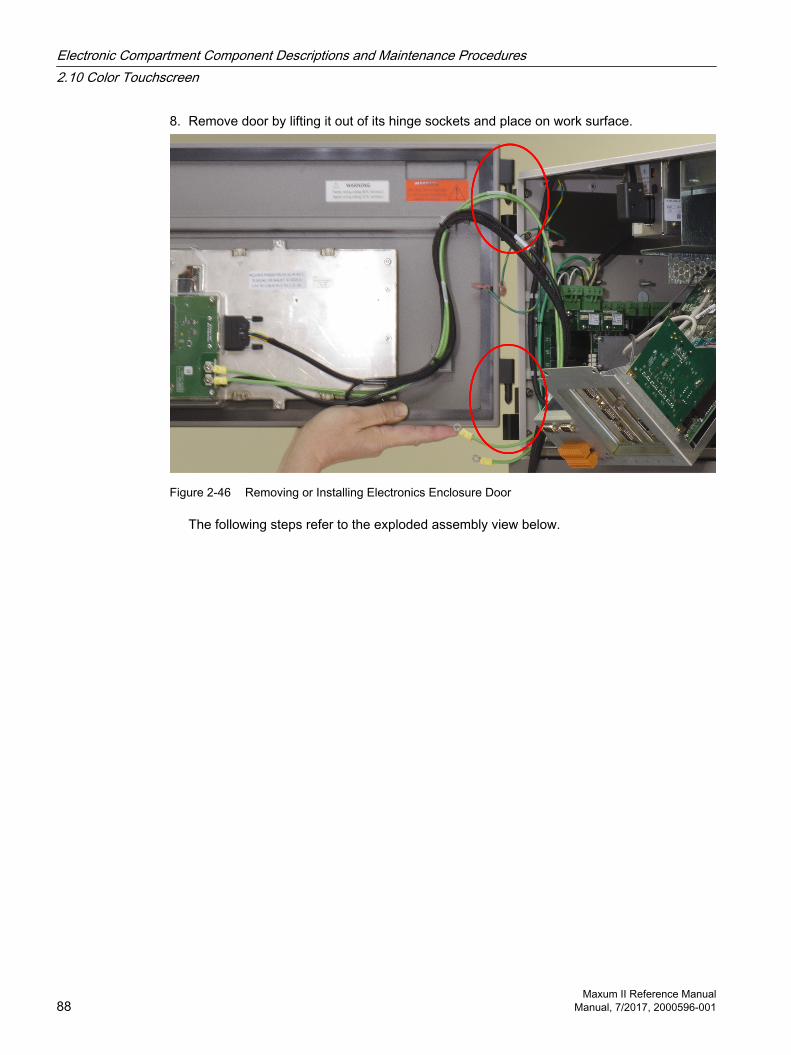
8. Remove door by lifting it out of its hinge sockets and place on work surface.
Figure 2-46 Removing or Installing Electronics Enclosure Door
The following steps refer to the exploded assembly view below.
Electronic Compartment Component Descriptions and Maintenance Procedures2.10 Color Touchscreen
Maxum II Reference Manual88 Manual, 7/2017, 2000596-001

Hole for
wire-tie
Hole for
wire-tie
ESD
ground
connection
points
D
B
E
E
E
E
E
E
D
Backlight
Connector
B
C
A
Intrinsic safety
ground wires
LCD
from
SIB3
Display
panel to
TIB cable
Wire-tie
anchors,
insertion
points
Figure 2-47 TIB Color Touchscreen Door Exploded View
9. Remove the TIB protective cover by removing the 4 screws. (A in exploded view) This allows access to two of the 6 mounting studs for the LCD assembly. (E in exploded view)
10.Disconnect the three connectors of the display cable assembly; the backlight connector, the TIB cable connector, and the LCD connector. (B in exploded view)
Electronic Compartment Component Descriptions and Maintenance Procedures2.10 Color Touchscreen
Maxum II Reference ManualManual, 7/2017, 2000596-001 89
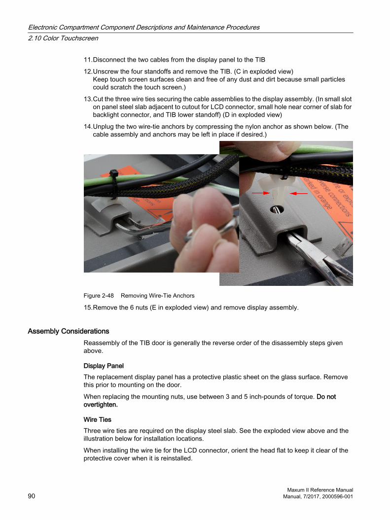
11.Disconnect the two cables from the display panel to the TIB
12.Unscrew the four standoffs and remove the TIB. (C in exploded view)Keep touch screen surfaces clean and free of any dust and dirt because small particles could scratch the touch screen.)
13.Cut the three wire ties securing the cable assemblies to the display assembly. (In small slot on panel steel slab adjacent to cutout for LCD connector, small hole near corner of slab for backlight connector, and TIB lower standoff) (D in exploded view)
14.Unplug the two wire-tie anchors by compressing the nylon anchor as shown below. (The cable assembly and anchors may be left in place if desired.)
Figure 2-48 Removing Wire-Tie Anchors
15.Remove the 6 nuts (E in exploded view) and remove display assembly.
Assembly ConsiderationsReassembly of the TIB door is generally the reverse order of the disassembly steps given above.
Display PanelThe replacement display panel has a protective plastic sheet on the glass surface. Remove this prior to mounting on the door.
When replacing the mounting nuts, use between 3 and 5 inch-pounds of torque. Do not overtighten.
Wire TiesThree wire ties are required on the display steel slab. See the exploded view above and the illustration below for installation locations.
When installing the wire tie for the LCD connector, orient the head flat to keep it clear of the protective cover when it is reinstalled.
Electronic Compartment Component Descriptions and Maintenance Procedures2.10 Color Touchscreen
Maxum II Reference Manual90 Manual, 7/2017, 2000596-001
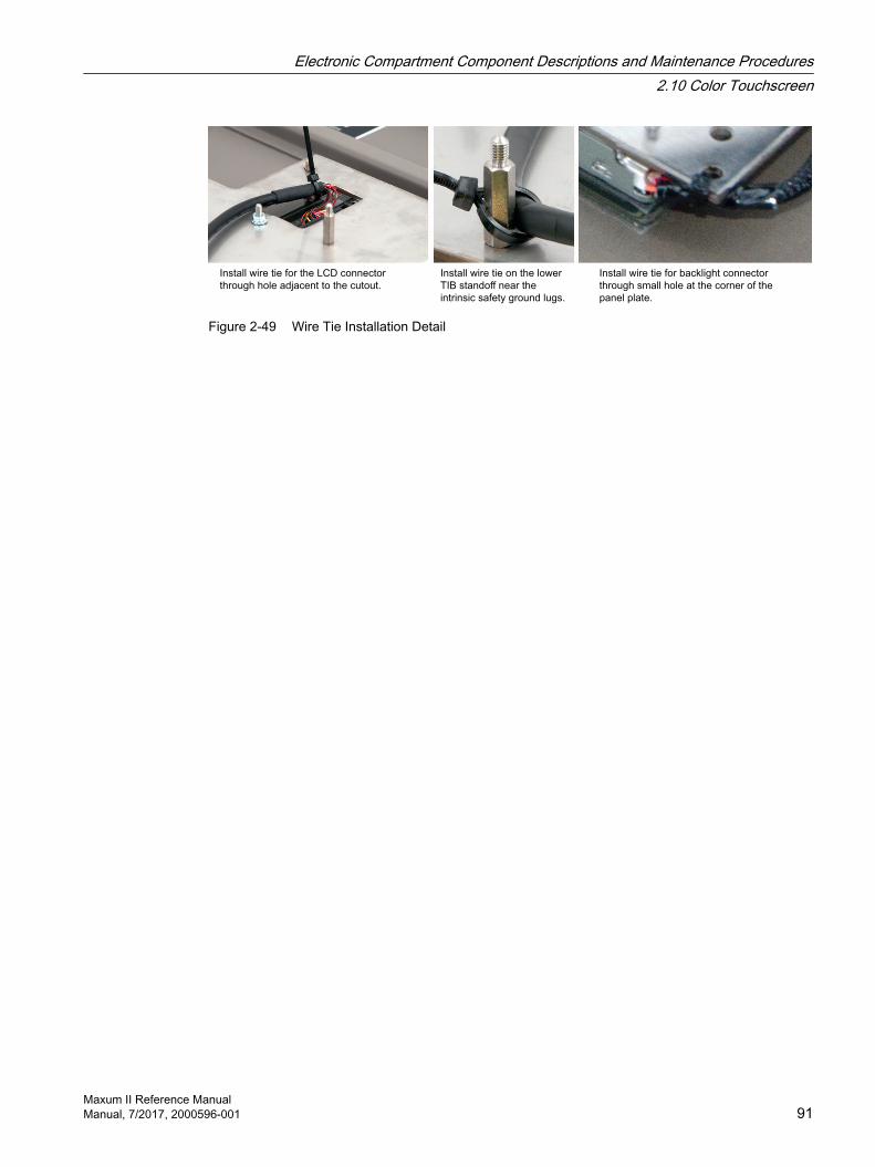
Install wire tie for the LCD connector
through hole adjacent to the cutout.
Install wire tie on the lower
TIB standoff near the
intrinsic safety ground lugs.
Install wire tie for backlight connector
through small hole at the corner of the
panel plate.
Figure 2-49 Wire Tie Installation Detail
Electronic Compartment Component Descriptions and Maintenance Procedures2.10 Color Touchscreen
Maxum II Reference ManualManual, 7/2017, 2000596-001 91

Electronic Compartment Component Descriptions and Maintenance Procedures2.10 Color Touchscreen
Maxum II Reference Manual92 Manual, 7/2017, 2000596-001

Specifications 3Table 3-1 General
Temperature control ±0.02°C (±0.05°F)Calibration Comparison measurement with external standard Type Manual or automatic Zero value Automatic baseline correction Span Standard sample cylinder (single or multipoint calibration possible)
Table 3-2 Measuring Response
Sensitivity (depending on applica‐tion)
±0.5% of span
Linearity (depending on application) ±2% of spanEffects of vibrations NegligibleRepeatability in % of full scale(Depending on application)
Range Value2 and 100% ±0.5%0.05 and 2% ±1%; 50 and 500 ppm ±2%5 and 50 ppm ±3%0.5 and 5 ppm ±5%
Table 3-3 Climatic conditions
Ambient temperature and humidity -18 to 50°C (0 to 122°F) application-dependentSpecific installations may require additional environmental constraints. See the custom documentation package. Note: If the Maxum II is exposed to high condensing humidity with the electronics open or without dry purge air applied, then it must be allowed to re-stabilize at the above stated conditions for at least 8 hours before electrical power is applied.** Depending on application characteristics such as number of detectors, oven tem‐perature, and electronic loading, the acceptable ambient temperature range may be reduced. For application-specific detail, contact Siemens through the Siemens Industry Online Support (SIOS) website:https://support.industry.siemens.com.
Altitude Up to 2000m (6561') for analyzers using 230VAC Supply Up to 3000m (9842') for analyzers using 115VAC Supply
Maxum II Reference ManualManual, 7/2017, 2000596-001 93

Table 3-4 Gas supply
Instrument air At least 350 kPa (50 psig) for units with Model 11 or Valco valves At least 825 kPa (120 psig) for units with Model 50 valves At least 175 kPa (25 psig) for airbath ovens; 85 l/min per oven Instrument air quality requirement: ISO-8573-1:2010 [3:2:3]
[ 3 : - : - ] Dust filtering down to 1 micron [ - : 2 : - ] Dew point of -40°C [ - : - : 3 ] Total hydrocarbon below 1 mg per cubic meter (appr. 0.8 ppmw)
Carrier gas Hydrogen, Nitrogen, Helium, Argon, or Synthetic Air in compressed gas cylinder, purity 99.999%, or hydrogen with a purity of 99.999% (depending on application).
Typical consumption quantity: 5 to 100 l/month per detector moduleCorrosion protection Purging with dry air to protect the electronics
Airbath oven with stainless steel lining Airless oven made of aluminum Steel lining painted on outside (epoxy powder coating)
These are general parameters that vary depending on the individual application and configuration.
Table 3-5 Typical Gas Requirements
Type Quality Pressure Typical ConsumptionCarrier gas Hydrogen
NitrogenHeliumArgonSynthetic Air
5.0 (≥ 99,999%) 500 to 1000 kPa (72.5 to 145 psig)
50 to 150 ml/min/train
Combustion gas Hydrogen 5.0 (≥ 99,999%) 500 to 1000 kPa (72.5 to 145 psig)
30 to 50 ml/min/FIDApprox. 100 ml/min/FPD
Combustion air Synthetic air Hydrocarbon free 500 to 1000 kPa (72.5 to 145 psig)
Approx. 400 ml/min/FIDApprox. 100 ml/min/FPD
Actuation air Instrument air Purge air(py purge)
Instrument air or Nitrogen
Instrument air 400 to 1655 kPa (58 to 240 psig)
Initial purge: Approx. 65l/minOperating purge: Approx. 3.5 l/min
Purge air(px purge)
Instrument air or Nitrogen
Instrument air 400 to 600 kPa (58 to 87 psig)
Initial purge: 60 to 80 l/minOperating purge: 12 to 18 l/min
Valve gas(for Model 50)
Instrument air 500 to 1000 kPa (72.5 to 145 psig)
Oven heating (for Airbath oven)
Instrument air 400 to 600 kPa (58 to 87 psig)
85 l/min/oven
Vortex cooler Instrument air 300 to 600 kPa (43.5 to 87 psig)
130 to 170 l/min
PTGC Instrument air 400 to 600 kPa (58 to 87 psig)
210 l/min
Specifications
Maxum II Reference Manual94 Manual, 7/2017, 2000596-001
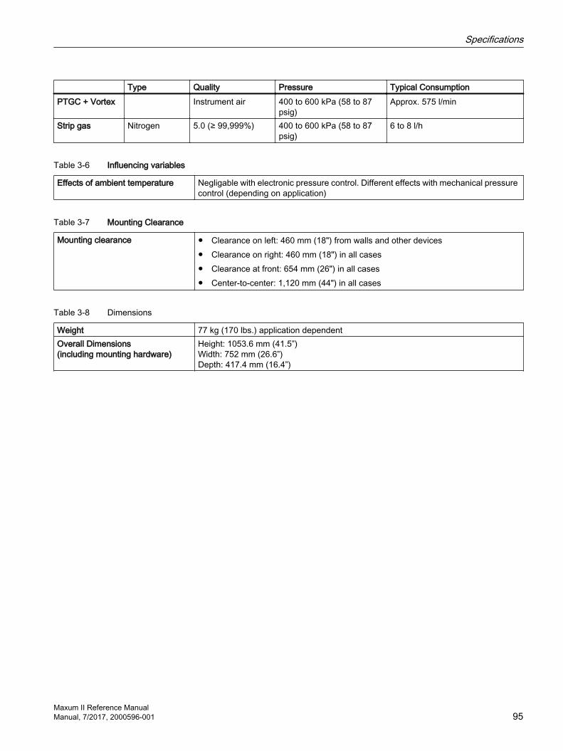
Type Quality Pressure Typical ConsumptionPTGC + Vortex Instrument air 400 to 600 kPa (58 to 87
psig)Approx. 575 l/min
Strip gas Nitrogen 5.0 (≥ 99,999%) 400 to 600 kPa (58 to 87 psig)
6 to 8 l/h
Table 3-6 Influencing variables
Effects of ambient temperature Negligable with electronic pressure control. Different effects with mechanical pressure control (depending on application)
Table 3-7 Mounting Clearance
Mounting clearance Clearance on left: 460 mm (18") from walls and other devices Clearance on right: 460 mm (18") in all cases Clearance at front: 654 mm (26") in all cases Center-to-center: 1,120 mm (44") in all cases
Table 3-8 Dimensions
Weight 77 kg (170 lbs.) application dependentOverall Dimensions(including mounting hardware)
Height: 1053.6 mm (41.5”)Width: 752 mm (26.6”)Depth: 417.4 mm (16.4”)
Specifications
Maxum II Reference ManualManual, 7/2017, 2000596-001 95

Figure 3-1 Maxum II Airless/Airbath Dimensions
Table 3-9 Configuration
Oven options Single isothermal airbath oven or divided airbath oven with two independent isothermal zones
Single oven or two independent, airless ovens in separate oven areas. Programmable-temperature (PTGC) oven
Detector options Thermal conductivity Flame ionization Flame photometry Pulse discharge detector in Helium ionization mode Pulse discharge detector in Photo-ionization mode Pulse discharge detector in Electron capture mode
Number of detectors 1, 2 or 3 in any combination of detector module types for airbath ovens (max. 2 FPDs)
1, or 2 in any combination of detector module types for airless ovens, up to 3 in special configurations
Specifications
Maxum II Reference Manual96 Manual, 7/2017, 2000596-001

Sampling and column valves Diaphragm valves Diaphragm piston valves Sliding vane rotary valves Slider valves Liquid injection valve
Valveless option Live switchingColumn options Packed, micropacked or capillary columnsRegulation of gas supply Up to 8 electronic pressure regulator channels and up to 6 mechanical pressure reg‐
ulators
Table 3-10 Enclosure Protection
Ingress protection IP54, Category 2Explosion protection Standard configurations:
Certified according to ATEX with air or nitrogen purging for Zone 1 (II2G Ex ... IIB + H2 ... Gb)
Suitable for use in non-hazardous areas and with non-dangerous conditions Certified according to CSA C/US for use in Class 1, Div. 1, Groups B, C, D with air
or nitrogen purging Certified according to CSA C/US for use in Class 1, Div. 2, Groups B, C, D. Important note! Purging of the electronics area with instrument air or nitrogen is rec‐ommended to maintain optimum measurement performance. The PDD is not certified for hazardous areas.
EMI/RFI design CE-compatible; in conformity with 2014/30/EU (EMC directive) CE-compatible; in conformity with 2014/35/EU (low-voltage directive) Tested according to EN 61010-1 / IEC 61010-1
Table 3-11 Electrical characteristics
Power supply Single-phase AC, 100 to 130 V or 195 to 260 V (selectable), 47 to 63 Hz Single oven: max. 1800 VA Dual oven: 2 circuits, max. 1800 VA each
Table 3-12 Electrical inputs and outputs
Standard input and output 2 analog outputs 4 digital outputs (1 for output of system faults, 3 are user-configurable) 4 digital inputs;
Card slots for optional inputs and outputs via internal I2C bus
2
Input and output cards I2C_AIO: 8 analog outputs, 8 analog inputs, 2 digital inputs I2C_DIO: 6 digital inputs and 8 digital outputs I2C_ADIO: 4 digital inputs and 4 digital outputs, 4 analog inputs and 4 analog
outputs
Specifications
Maxum II Reference ManualManual, 7/2017, 2000596-001 97
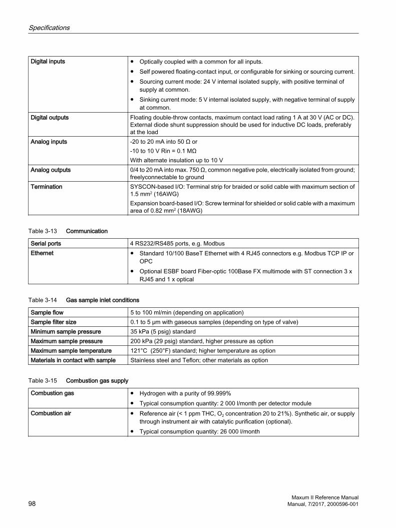
Digital inputs Optically coupled with a common for all inputs. Self powered floating-contact input, or configurable for sinking or sourcing current. Sourcing current mode: 24 V internal isolated supply, with positive terminal of
supply at common. Sinking current mode: 5 V internal isolated supply, with negative terminal of supply
at common.Digital outputs Floating double-throw contacts, maximum contact load rating 1 A at 30 V (AC or DC).
External diode shunt suppression should be used for inductive DC loads, preferably at the load
Analog inputs -20 to 20 mA into 50 Ω or-10 to 10 V Rin = 0.1 MΩWith alternate insulation up to 10 V
Analog outputs 0/4 to 20 mA into max. 750 Ω, common negative pole, electrically isolated from ground; freelyconnectable to ground
Termination SYSCON-based I/O: Terminal strip for braided or solid cable with maximum section of 1.5 mm2 (16AWG) Expansion board-based I/O: Screw terminal for shielded or solid cable with a maximum area of 0.82 mm2 (18AWG)
Table 3-13 Communication
Serial ports 4 RS232/RS485 ports, e.g. ModbusEthernet Standard 10/100 BaseT Ethernet with 4 RJ45 connectors e.g. Modbus TCP IP or
OPC Optional ESBF board Fiber-optic 100Base FX multimode with ST connection 3 x
RJ45 and 1 x optical
Table 3-14 Gas sample inlet conditions
Sample flow 5 to 100 ml/min (depending on application)Sample filter size 0.1 to 5 μm with gaseous samples (depending on type of valve)Minimum sample pressure 35 kPa (5 psig) standardMaximum sample pressure 200 kPa (29 psig) standard, higher pressure as optionMaximum sample temperature 121°C (250°F) standard; higher temperature as optionMaterials in contact with sample Stainless steel and Teflon; other materials as option
Table 3-15 Combustion gas supply
Combustion gas Hydrogen with a purity of 99.999% Typical consumption quantity: 2 000 l/month per detector module
Combustion air Reference air (< 1 ppm THC, O2 concentration 20 to 21%). Synthetic air, or supply through instrument air with catalytic purification (optional).
Typical consumption quantity: 26 000 l/month
Specifications
Maxum II Reference Manual98 Manual, 7/2017, 2000596-001

Index
AABH1, 74ABH2, 74
FFuses, 74
HHeater Termination Plug, 31
IIO Board DI Mode Switch, 57IO Board Status LEDs, 57
SSolid State Relay Module, 74
TTEMP CONTROL, 31
Maxum II Reference ManualManual, 7/2017, 2000596-001 99

Index
Maxum II Reference Manual100 Manual, 7/2017, 2000596-001
Related Documents