TECHNICAL CATALOG 32M-05005-03 MAXON Series 8000 Air Actuated Valves for liquid service • Pneumatically actuated valves with powerful closing spring for reliable operation • Compact design with integral solenoid, quick exhaust and position switches that protects components, simplifies piping and minimizes space requirements • FM, CE, CSA, IECEx, INMETRO, CCC, KC, UKCA and ATEX approvals • safety shut-off valves • Hazardous Location approved: Intrinsically Safe for Class I, Div. 1 (and ATEX Zone 1/21); Non- Incendive for Class I, Div. 2 • Large top mounted 360-degree open-shut visual position indication, configurable in red/green or yellow/black color schemes • Cast iron and carbon steel body assemblies with internal trim options to handle non-corrosive fluids • Ambient temperature ranges of -40°F (-40°C) to 140°F (60°C); • Fluid temperature range of -40°F (-40°C) to 550°F (288°C) • Application flexibility provided with 3/8" (DN10) through 1-1/4" (DN32) line sizes & line pressures up to 740 psig • Actuator assemblies are field-replaceable and available in 120VAC 50/60 Hz, 240VAC 50/ 60 Hz, and 24VDC (with low power option), rated for NEMA 4, NEMA 4X and IP65 • Option available to utilize customer-supplied, externally mounted solenoids. When used in hazardous locations, the component must be rated for the Class and Division of the hazardous area. • Option available for speed control for adjustment of actuation speed. • Option available for manual reset (a control mounted on the valve must be physically reset for valve to actuate--but will then operate normally until tripped).

Welcome message from author
This document is posted to help you gain knowledge. Please leave a comment to let me know what you think about it! Share it to your friends and learn new things together.
Transcript

TECHNICAL CATALOG
32M-05005-03
MAXON Series 8000 Air Actuated Valves for liquid service
• Pneumatically actuated valves with powerful closing spring for reliable operation
• Compact design with integral solenoid, quick exhaust and position switches that protects components, simplifies piping and minimizes space requirements
• FM, CE, CSA, IECEx, INMETRO, CCC, KC, UKCA and ATEX approvals
• safety shut-off valves
• Hazardous Location approved: Intrinsically Safe for Class I, Div. 1 (and ATEX Zone 1/21); Non-Incendive for Class I, Div. 2
• Large top mounted 360-degree open-shut visual position indication, configurable in red/green or yellow/black color schemes
• Cast iron and carbon steel body assemblies with internal trim options to handle non-corrosive fluids
• Ambient temperature ranges of -40°F (-40°C) to 140°F (60°C);
• Fluid temperature range of -40°F (-40°C) to 550°F (288°C)
• Application flexibility provided with 3/8" (DN10) through 1-1/4" (DN32) line sizes & line pressures up to 740 psig
• Actuator assemblies are field-replaceable and available in 120VAC 50/60 Hz, 240VAC 50/ 60 Hz, and 24VDC (with low power option), rated for NEMA 4, NEMA 4X and IP65
• Option available to utilize customer-supplied, externally mounted solenoids. When used in hazardous locations, the component must be rated for the Class and Division of the hazardous area.
• Option available for speed control for adjustment of actuation speed.
• Option available for manual reset (a control mounted on the valve must be physically reset for valve to actuate--but will then operate normally until tripped).

Table of contentsSeries 8000 Air Actuated Valves for liquid service
32M-05005-03 2 E-i-08-21
MAXON Series 8000 Air Actuated Valves for liquid service . . . . . . . . . . . . . . . . . . . . . . . . . . . . . . . . . . . . . . . 1Features & Benefits . . . . . . . . . . . . . . . . . . . . . . . . . . . . . . . . . . . 3Switch Assemblies . . . . . . . . . . . . . . . . . . . . . . . . . . . . . . . . . . . . . . . 4Body and Trim Selections. . . . . . . . . . . . . . . . . . . . . . . . . . . . . . . . 4
AGENCY APPROVALS AND CERTIFICATIONS . . . . . . . . . 5Valve cycle requirements . . . . . . . . . . . . . . . . . . . . . . . . . . . . . . . . 5
VALVE MODEL NUMBER DESCRIPTION . . . . . . . . . . . . . . 6Maximum operating pressure ratings . . . . . . . . . . . . . . . . . 8Valve Body Capacities/Specifications . . . . . . . . . . . . . . . . . 9Swinging gate body/trim specifications . . . . . . . . . . . . . .11Valve Body Assembly Options & Accessories . . . . . . . . .12Valve Actuator Assembly Specifications . . . . . . . . . . . . . .16Electrical Data . . . . . . . . . . . . . . . . . . . . . . . . . . . . . . . . . . . . . . . . 17General. . . . . . . . . . . . . . . . . . . . . . . . . . . . . . . . . . . . . . . . . . . . . . . . . . 17
General Purpose - Series 8031 & 8131 . . . . . . . . . . . . . . . . . . . . . . 18Class I, Div. 2 Hazardous Location - Series 8032 & 8132 . . . 18
Class I Div. 1 - Series 8033 & 8133 . . . . . . . . . . . . . . . . . . . . . 19Control drawing for customer-supplied, externally mounted solenoids . . . . . . . . . . . . . . . . . . . . . . . . . . . . . . . . . . . . . 20Barrier selection criteria for solenoid . . . . . . . . . . . . . . . . . . . 22Barrier selection criteria for switch . . . . . . . . . . . . . . . . . . . . . 22
Dimensions & Weights . . . . . . . . . . . . . . . . . . . . . . . . . . . . . . . .23Minimum required cylinder pressures . . . . . . . . . . . . . . . .28Accessories . . . . . . . . . . . . . . . . . . . . . . . . . . . . . . . . . . . . . . . . . . .32Speed Control Set Kits. . . . . . . . . . . . . . . . . . . . . . . . . . . . . . . . . . 32
INSTALLATION, OPERATION AND MAINTENANCE INSTRUCTIONS . . . . . . . . . . . . . . . . . . . . . . . . . . . . . . . . . . . . . .33Description. . . . . . . . . . . . . . . . . . . . . . . . . . . . . . . . . . . . . . . . . . . . . . 33Nameplate and Abbreviations . . . . . . . . . . . . . . . . . . . . . . . . . . 33Component identification . . . . . . . . . . . . . . . . . . . . . . . . . . . . . . 34Installation. . . . . . . . . . . . . . . . . . . . . . . . . . . . . . . . . . . . . . . . . . . . . . 35Operating characteristics. . . . . . . . . . . . . . . . . . . . . . . . . . . . . . . 36Auxiliary Features. . . . . . . . . . . . . . . . . . . . . . . . . . . . . . . . . . . . . . . 36Operating Environment. . . . . . . . . . . . . . . . . . . . . . . . . . . . . . . . . 36
Electrical Data . . . . . . . . . . . . . . . . . . . . . . . . . . . . . . . . . . . . . . . .37Normally-Closed Shut-Off Valves . . . . . . . . . . . . . . . . . . . . . . 37
General Purpose Normally-Closed Valves . . . . . . . . . . . . . . . . . . . 37Class I, Div. 2 Hazardous Location Normally-Closed Valves 37Class I, Div. 1 and ATEX Zone 1 Intrinsically Safe Hazardous Location Normally-Closed Valves. . . . . . . . . . . . . . . . . . . . . . . . . . . . 37Class I, Div. 1 and ATEX Zone 1 Intrinsically Safe Hazardous Location Normally-Closed Valves. . . . . . . . . . . . . . . . . . . . . . . . . . . .38
Actuator Assembly Rotation/Replacement . . . . . . . . . . .39Field Installation of Valve Position Switch . . . . . . . . . . . .41Field Replacement Items . . . . . . . . . . . . . . . . . . . . . . . . . . . . . . . 41Replacement Switches . . . . . . . . . . . . . . . . . . . . . . . . . . . . . . . . . 41Add Switches. . . . . . . . . . . . . . . . . . . . . . . . . . . . . . . . . . . . . . . . . . . . 41
Operating Instructions . . . . . . . . . . . . . . . . . . . . . . . . . . . . . . .43Alternate operator pressures . . . . . . . . . . . . . . . . . . . . . . . . . . . 43
Maintenance Instructions . . . . . . . . . . . . . . . . . . . . . . . . . . . .43Solenoid replacement procedure. . . . . . . . . . . . . . . . . . . . . . .44

Series 8000 Air Actuated Valves for liquid service
E-i-08-21 3 32M-05005-03
Features & BenefitsMAXON Series 8000 Air Actuated Valves combine a unique space-saving design with a maintenance-free body and a replaceable actuator for easy installation and smooth, trouble-free operation.
The valve's quick exhaust and powerful closing spring provide valve closure in less than one second and reliable, long-life operation.
Series 8000 Valve's compact design simplifies piping design and minimizes space requirements.
The field-replaceable actuator provides easier mainte-nance and reduced downtime. The actuator can also be rotated around the valve body in 90° increments to fit your specific application requirements.
A unique stem seal design eliminates packing adjust-ments for reduced maintenance and minimized drag on closing.
The large top-mounted open-shut indicator is visible from all angles for easy proof of valve position. FM and CSA approvals for use as a fuel safety shut-off valve mak-ing easy integration with worldwide certifications.

Series 8000 Air Actuated Valves for liquid service
32M-05005-03 4 E-i-08-21
Switch Assemblies• Provides positive valve position - open or closed
• Complies with "proof of closure" requirements
• Easily integrates with an analog control system, DCS or PLC
VOS2/VCS2 Switch Assemblies with Terminal Blocks and Leads Mounted
• Factory-mounted to terminal strip to shorten installa-tion time
• Easy replacement (2 screws)
• Locating pins guarantee accurate mounting position
• No adjustment required
V7 Assembly for General Purpose and Intrinsically Safe Class I Div. 1 Areas and Zone 0 Areas
IP67 Switch Assembly for Non-Incendive Class I Div. 2 and Zone 2 Areas and Optional Class I Div. 1 Areas and Zone 0 Areas
Body and Trim SelectionsCast iron and carbon steel body assemblies feature metal-to-metal seating that meets FCI 70-2 control valve standard for Class VI seat leakage. Industrial-strength high alloy discs and hex nuts are available. Contact MAX-ON with your specific application details.
Valve bodies are available in your choice of threaded, flanged and socket-welded connections. Bodies are cur-rently available in 3/8" (DN10) through 1-1/4" (DN32).
Normally-closed shut-off valves use instrument air to open quickly. Removal of electrical signal allows release of control air through solenoid and quick exhaust valve allowing the Series 8000 Valve to close in less than one second. Optional speed control set kit available for slower opening adjustment.
Series 8031, 8032 & 8033require 30-100 psig instrument air
Series 8131, 8132 & 8133require 30-100 psig instrument air

Series 8000 Air Actuated Valves for liquid service
E-i-08-21 5 32M-05005-03
AGENCY APPROVALS AND CERTIFICATIONS(Will vary with specific options selected)
General Purpose Valves 8131, 8031 Series
Non-Incendive/Non-Sparking Valves 8131, 8031 Series
Intrinsically Safe Valves 8131, 8031 Series
Standards Markings Standards Markings Standards Markings
FM Approvals FM 7400
FM 3611FM 3600FM 3810
NEMA 250IIEC 60529
Class I, Div 2, Groups ABCD, T4Class II, Div 2, Groups FG, T4
Class III, Div 2, T4 FM 3610FM 3600FM 3810
NEMA 250IIEC 60529
Class I, Div 1, Groups ABCD, T5Class II, Div 1, Groups EFG, T5
Class III, Div 1, T5
CSA/SIRA- IECEx Certification Not Applicable None
IEC 60079-0IEC 60079-15IEC 60079-31
IECEx SIR 19.0017XEx nA nC IIC T4 Gc (T5 w/ IS coil)
Ex tc IIIC T135°C Dc-50°C ≤ Ta ≤ +60°C (+50 w/ IS coil)
IEC 60079-0IEC 60079-11
IECEx SIR 19.0017XEx ia IIC T5 Gb
Ex tc IIIC T135°C Dc-50°C ≤ Ta ≤ +50°C
CSA International CSA 6.5 - 2015
CSA C22.2: No. 213-M1987
No. 1010.1CAN/CSA-E60079-0
CAN/CSA-E60079-15
Class I, Div 2, Groups ABCD, T4Class II, Div 2, Groups FG, T4
Class III, Div 2, T4Ex nA IIC T4 Ta=-50°C to +60°C (w/ std coil)Ex nA IIC T5 Ta=-50°C to +50°C (w/ IS coil)
(Zone 2 approval)
03.1433937X
CSA C22.2: No. 157-M1992
No. 1010.1CAN/CSA-E60079-0
CAN/CSA-E60079-11
Class I, Div 1, Groups ABCD, T5Class II, Div 1, Groups EFG, T5
Class III, Div 1, T5Ex ia IIC T5, -50°C < Ta < +50°C
(Zone 0 Approval)
Ex ia
03.1433937X
United Kingdom Approvals (Hazardous Locations) 1
Not Applicable None Not Applicable None
BS EN 60079-0BS EN 60079-11BS EN 60529 +A1
BS EN 13463-1BS EN 13463-5
Sira 19ATEX2040XII 2GD
Ex ia IIC T5 GbEx ia IIIC T100°C Db
Ta = -50°C to +50°C IP65
1725
NCC/Inmetro Not Applicable None
ABNT NBR: IEC 60079-0
IEC 60079-15 IEC 60079-31
Ex nA nC IIC T4 Gc -50°C ≤ Ta ≤ +60°
Ex tc IIIC T135°C Dc IP65
Ex nA nC IIC T5 Gc -50°C ≤ Ta ≤ +50°C
Ex tc IIIC T135°C Dc IP65
ABNT NBR: IEC 60079-0
IEC 60079-11 IEC 60079-31
Ex ia IIC T5 Gb
-50°C ≤ Ta ≤ +50°CEx tc IIIC T135°C Dc IP65
KTL Not Applicable NoneAnnouncement No.
2010-36 of Ministry of Employment and Labor
Ex nA nC IIC T4 (-50°C ≤ Ta ≤ +60°C)
16-KA4BO-0566X
Announcement No. 2010-36 of Ministry of Employment and
Labor
Ex ia IIC T5 (-50°C ≤ Ta ≤ +50°C)
16-KA4BO-0565X
Chinese Approvals None None
GB 3836.1, GB 3836.8,
GB 12476.1, GB 12476.5
Ex nA nC IIC T4 Gc (T5 w/ IS coil) -50°C < Ta < +60°C (+50°C w/ IS coil),
Ex tD A22 IP65 T135°CGB 3836.1, GB 3836.4,
GB 12476.1, GB 12476.5
Ex ia IIC T5 Gb, -50°C < Ta < +50°C,
Ex tD A22 IP65 T135°C
European Approvals 1 (Hazardous Locations)
Not Applicable None Not Applicable None
EN 60079-0EN 60079-11EN 60529 +A1
EN 13463-1EN 13463-5
Sira 19ATEX2040XII 2GD
Ex ia IIC T5 GbEx ia IIIC T100°C Db
Ta = -50°C to +50°C IP65
2809
1 Product certified to meet the following: ATEX Regulation (2014/34/EU)
Valve cycle requirementsThis is based on the standards that MAXON valves are approved to and the corresponding minimum number of cycles to be completed without failure as shown in the chart below.
CSA (CSA 6.5) FM (FM 7400)Automatic - Normally-Closed Series 8031, 8131, 8032, 8132, 8033, 8133 100,000 20,000

Series 8000 Air Actuated Valves for liquid service
32M-05005-03 6 E-i-08-21
VALVE MODEL NUMBER DESCRIPTIONEvery MAXON Series 8000 Valve can be accurately identified by the model number shown on the valve nameplate. The example below shows a typical Series 8000 Valve model number, along with the available choices for each item represented in the model number. The first five choices determine the valve’s configured item number. Valve body and actuator options are identified by the next eight characters in the model number.
Configured Item Number Valve Body Actuator
Valv
e Size
Flow
Cap
acity
Pres
sure
Ra
ting
Norm
al
Posit
ion
Area
Cl
assifi
catio
n
Body
Co
nnec
tion
Body
Sea
ls &
Stem
Pac
king
Body
Mat
eria
l
Inte
rnal
Trim
Pa
ckag
e
Prim
ary
Volta
ge
Switc
h Op
tion
Encl
osur
e Ra
ting
Inst
ruct
ion
Lang
uage
Visu
al
Indi
catio
n
038 S 81 3 1 - A B 1 D - B 1 A 0 1
Valve Size038 – 3/8” (DN 10) 050 – 1/2” (DN 15) 075 – 3/4” (DN 20) 100 – 1” (DN 25) 125 – 1-1/4” (DN 32)
Flow CapacityH – High
S – Standard
Operating Pressure Rating80 – Pneumatic Standard Pressure
81 – Pneumatic High Pressure
Normal Position3 – Normally-Closed Liquid Shut-Off Valve
Area Classification1 – General Purpose
2 – Non-incendive, Class I, II and III Divi-sion 2
3 – Intrinsically Safe, Class I, II and III Di-vision 1 (and ATEX Zone 1/21) 1
4 – Valve Body Only
1 122°F maximum ambient temperature limit 2 Not a selection on Body Only
Body Connection
A – NPT
E – Socket Welded Nipple
F – Socket Welded Nipple w/Class 150 (PN20) Flanges
G – Socket Welded Nipple w/Class 300 (PN50) Flanges
H – EN 1092-1 PN16 Flanged
I – Socket Welded Nipple w/Class 600 (PN110) Flanges
J – Butt-Welded Nipple X – Special
U – Actuator Only
Body Seals & Stem PackingA – Buna-N w/PTFE
B – Viton™ w/PTFE
C – Ethylene-Propylene w/PTFE
D – Kalrez® w/Grafoil®
X – Special
U – Actuator Only
Body Material1 – Cast Iron
2 – Carbon Steel
X – Special
U – Actuator Only
Internal Trim PackageB – Ductile
D – Stellite
P – PEEK
X – Special
U – Actuator Only
Primary Voltage2
A – 120VAC 50Hz B – 120VAC 60Hz D – 240VAC 50Hz E – 240VAC 60Hz G – 24VDC H – 24VDC IS 1 J – 24VDC IS-ATEX 1 X – Special Z – None (customer-supplied, external mount)
Switch Option 2
0 – None 1 – VOS1/VCS1 - V7 2 – VOS2/VCS2 - V7 3 – VOS1/VCS1 - IP67 4 – VOS2/VCS2 - IP67 X – Special
Enclosure Rating 2
A – NEMA 4, IP65 B – NEMA 4X, IP65 X – Special
Instruction Language 2
0 – English 1 – French 3 – German 4 – Portuguese 5 – Spanish 6 – Chinese
Visual Indication 2
1 – Red-closed/green-open 2 – Red-open/green closed 3 – Yellow-open/black-closed

Series 8000 Air Actuated Valves for liquid service
E-i-08-21 7 32M-05005-03
VALVE BODY ASSEMBLY OPTIONS & SPECIFICATIONSSeries 8000 normally-closed liquid shut-off valves
Nominal pipe size Flow capacity Actuator pressure class
Body connections available Body material Trim package options Cv rating
3/8” (DN10) Standard High A,C 1 D 3.4
1/2” (DN15) Standard HighA,C 1,2
D, P 3.4E,F,G,I,J 2
3/4” (DN20) Standard HighA,C 1,2
D, P 9.6E,F,G,I,J 2
1” (DN25) StandardStandard
A,C 1,2
B,D,P 12E,F,G,I,J 2
HighA,C 1,2
E,F,G,I,J 2
1-1/4”(DN32)
StandardStandard
A,C 1,2
B,D,P 17E,F,G,I,J 2
HighA,C 1,2
E,F,G,I,J 2
High Cap.Standard A,C,E,F,G,I,J 2
D 45High A,C,E,F,G,I,J 2
Body Connections:A - NPT
C - ISO 7-1 Threaded
E - Socket Welded Nipple
F - Socket Welded Nipple w/Class 150 (PN20) Flange
G - Socket Welded Nipple w/Class 300 (PN50) Flange
H - EN 1092-1 (PN16) Flanged
I - Socket Welded Nipple w/ Class 600 (PN110) Flange
J - Butt-Welded Nipple
X - Special
Body Material: 1 - Cast Iron
2 - Cast Steel
Trim Packag Options and Typical Material:B - Ductile
D - Stellite
P - PEEK
Body Seals:Standard elastomers are Buna-N, Viton™, Ethylene-Propylene and Kalrez®.
Standard packings are PTFE and Grafoil®.
Series 8000 Air Actuated Valves for liquid service
32M-05005-03 8 E-i-08-21
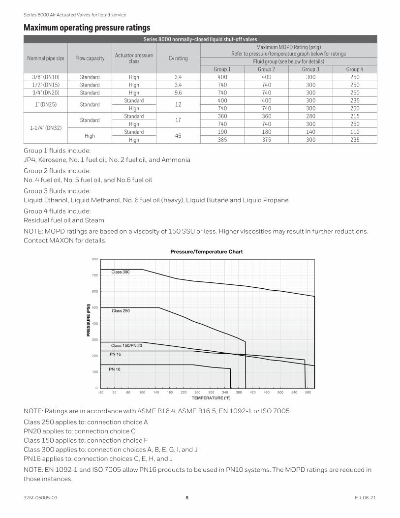
Maximum operating pressure ratingsSeries 8000 normally-closed liquid shut-off valves
Nominal pipe size Flow capacity Actuator pressure class Cv rating
Maximum MOPD Rating (psig)Refer to pressure/temperature graph below for ratings
Fluid group (see below for details)Group 1 Group 2 Group 3 Group 4
3/8” (DN10) Standard High 3.4 400 400 300 2501/2” (DN15) Standard High 3.4 740 740 300 2503/4” (DN20) Standard High 9.6 740 740 300 250
1” (DN25) StandardStandard
12400 400 300 235
High 740 740 300 250
1-1/4” (DN32)Standard
Standard17
360 360 280 215High 740 740 300 250
HighStandard
45190 180 140 110
High 385 375 300 235
Group 1 fluids include: JP4, Kerosene, No. 1 fuel oil, No. 2 fuel oil, and Ammonia
Group 2 fluids include: No. 4 fuel oil, No. 5 fuel oil, and No.6 fuel oil
Group 3 fluids include: Liquid Ethanol, Liquid Methanol, No. 6 fuel oil (heavy), Liquid Butane and Liquid Propane
Group 4 fluids include: Residual fuel oil and Steam
NOTE: MOPD ratings are based on a viscosity of 150 SSU or less. Higher viscosities may result in further reductions. Contact MAXON for details.
0
100
200
300
400
500
600
700
800
-20 20 60 100 140 180 220 260 300 340 380 420 460 500 540 580
PR
ES
SU
RE
(PS
I)
TEMPERATURE (°F)
PN 16
PN 10
Pressure/Temperature Chart
Class 300
Class 250
Class 150/PN 20
NOTE: Ratings are in accordance with ASME B16.4, ASME B16.5, EN 1092-1 or ISO 7005.
Class 250 applies to: connection choice A PN20 applies to: connection choice C Class 150 applies to: connection choice F Class 300 applies to: connection choices A, B, E, G, I, and J PN16 applies to: connection choices C, E, H, and J
NOTE: EN 1092-1 and ISO 7005 allow PN16 products to be used in PN10 systems. The MOPD ratings are reduced in those instances.

Series 8000 Air Actuated Valves for liquid service
E-i-08-21 9 32M-05005-03
Valve Body Capacities/SpecificationsBody
MaterialEnd
ConnectionsPipe Size (in
inches) Cv Factor
Gray Iron Threaded
.375 & .5 3.4
.759.620
11220
1.251745
Cast SteelThreaded
&Flanged
.5 3.4.75 9.61 12
1.251745
Each complete valve assembly must include one of these valve bodies, regardless of ultimate series designation.
Flows through the valve body and resulting pressure drops may be estimated by inserting your specific condi-tions into the following formula and using flow factors given for each valve body.
Gases: Q = (1360) × (Cv) × ( )×( )(P1 + P2)G Tf
(P1 - P2)2
Liquids: V = (Cv) × ( )(P1 - P2)Gf
Where: ρ ρG = Gas specific gravity (air = 1.0)
Gf = Specific gravity @ flowing temperature °F
P1 = Inlet pressure PSIA (14.7 psi + psi gauge)
P2 = Outlet pressure PSIA (14.7 psi + psi gauge)
Q = Cubic feet per hour @ 14.7 PSIA and 60°F
Tf = Flowing temperature absolute (460° + °F)
V = Flow in U.S. gallons/minute of water

Series 8000 Air Actuated Valves for liquid service
32M-05005-03 10 E-i-08-21
Valve Body Capacities with #2 OilTo select a valve for your application, use either Cv factor calculations, or this graph showing approximate pressure drop at various flows of #2 oil.
Typically, pressure drop for fuel flows should not exceed 10% of inlet pressure.
50000
5000
500
500.1 1.0 10.0
125 H (Cv=45)
125 S (Cv=17)
100 S (Cv=12)
075 S (Cv=9.6)
050 S (Cv=3.4) 038 S (Cv=3.4)
Maxon SSOV Liquid Flow Capacities
ΔP – Pressure Drop (psi)
Flow
rate
(US
Gal
/H) -
No.
2 O
il (s
.g. =
.87)
For preheated #5 or #6 oil, multiply the required flow rate in GPH by the factor given in the table at right, then select a valve based upon that equivalent flow of #2 oil and the allowable drop.
Oil Grade #5 #6°F @ Inlet 125 160 120 140 180 210 220
Factor 1.43 1.11 2.86 2.00 1.25 1.11 1.05
For example: To size for 5 PSIG drop with a 3500 GPH flow of #6 oil preheated to 140°F, the multiplier is 2. Equivalent flow of #2 oil is then 3500 x 2, or 7000 GPH. Chart shows that a 5 PSIG drop will require use of a valve body having a Cv factor of at least 45.

Series 8000 Air Actuated Valves for liquid service
E-i-08-21 11 32M-05005-03
Swinging gate body/trim specifications3/8” (DN10) through 3/4” (DN20) threaded body valves
1) Body o-ring2) Body o-ring3) Stem o-ring4) Stem packing ring5) Body6) Hex nut / renewable seat7) Stem bushing8) Stem9) Stem spring10) Disc carrier 11) Disc12) Disc spring13) Back-up rings14) Body gaskets15) Stem bushing gasket16) Packing nut
9
10
12115146
1
316
13
8 15
7
2
4
1” (DN25) to 1-1/4” (DN32) threaded body valves
1) Body o-ring3) Stem o-ring4) Stem packing ring5) Body6) Hex nut / renewable seat7) Stem bushing8) Stem9) Stem spring10) Disc carrier 11) Disc12) Disc spring13) Back-up rings14) Body gaskets
10 51211141
6
13
7
9
8
43
13

Series 8000 Air Actuated Valves for liquid service
32M-05005-03 12 E-i-08-21
Valve Body Assembly Options & Accessories3/8” (DN10) through 3/4” (DN20) Valves
146
111 10 12
5
9
8
4162
713
322
1920
21
23
25 26
15
A
A
SECTION A-A

Series 8000 Air Actuated Valves for liquid service
E-i-08-21 13 32M-05005-03
1” (DN25) to 1-1/4” (DN32) Valves
1
14
11 10 12
6
15
8
2 137
3
5
9
22
1920
21
23
25 26B
B
SECTION B-B

Series 8000 Air Actuated Valves for liquid service
32M-05005-03 14 E-i-08-21
Body seals and packing materials
Item No. DescriptionMaterial
Standard Temperature High Temperature1 Body o-ring Viton™ Kalrez®2 Body o-ring Viton™ Kalrez®3 Inner stem thrust ring PTFE Grafoil®4 Stem packing ring PTFE Meldin® 7001
Body, seat & outlet specificationsItem No. Description Trim 1 Trim 2
5 Body Cast IronASTM A126,
Class B
Carbon SteelASTM A216
Gr. WCB6 Hex nut / renewable seat
Note: Nippled valves or nippled valves with flanges are available only in steel.
Internal trim material specificationsItem No. Description Trim B Trim D Trim P
6 Hex nut / renewable seat (face only) 420 Stainless Steel Stellite Hard-faced Steel Stellite Hard-faced Steel
7 Stem bushing Zinc Plated Steel Zinc Plated Steel Zinc Plated Steel8 Stem 416 Stainless Steel 416 Stainless Steel 416 Stainless Steel9 Stem spring 302 Stainless Steel 302 Stainless Steel 302 Stainless Steel
10 Disc carrier C-1029 Forged Steel C-1029 Forged Steel C-1029 Forged Steel w/PEEK insert
11 Disc Nodular Iron Stellite Hard-faced Steel Stellite Hard-faced Steel12 Disc spring 302 Stainless Steel 302 Stainless Steel 302 Stainless Steel13 Back-up rings PTFE PTFE PTFE14 Body gaskets 1008 Steel 1008 Steel 1008 Steel15 Stem bushing gasket 1008 Steel 1008 Steel 1008 Steel16 Packing nut Zinc-plated 12L14 Steel Zinc-plated 12L14 Steel Zinc-plated 12L14 Steel
Adapter base material specifications
Item No. DescriptionPressure Rating
Standard High
19 Adapter base Cast aluminum ASTM B26 T6 temper
Cast iron ASTM A159 Gr. 3000 1
20 Sleeve bearing Bronze Bronze21 Operating rod 17-4PH Stainless steel 17-4PH Stainless steel22 Stop collar #303 Stainless steel #303 Stainless steel23 Spring 17-7PH Stainless steel wire 17-7PH Stainless steel wire25 Upper spring retainer Steel 2 Steel 2
26 Spring retainer keeper Steel 2 Steel 2
1 3/8” - 3/4” high pressure adapter base is cast aluminum2 Treated for rust prevention

Series 8000 Air Actuated Valves for liquid service
E-i-08-21 15 32M-05005-03
Media compatibility and valve approval certifications
Media Media CodeSuggested Material Options
MOPDRating 4, 5
Agency Approvals and CertificationsBody Seals &Stem packing Body Material Internal Trim FM CSA 7 ATEX
Ammonia (anhydrous) AMMA C,D 1,2 D Std. X X XEthanol (liquid) ETHL A,C,D 2 D,P Note 2 X X X
JP4 JP4 A,B,D 1,2 B,D Std. X X XKerosene KERO A,B,D 1,2 B,D Std. X X X
Methanol (liquid) METHL A,C,D 1,2 B,D,P Note 2 X X XNo. 1 Fuel Oil NO1OIL A,B,D 1,2 B,D Std. X X XNo. 2 Fuel Oil NO2OIL A,B,D 1,2 B,D Std. X X X
No. 4 Fuel Oil (125 SSU max) 6 NO4OIL A,B,D 1,2 B,D Note 1 X X XNo. 5 Fuel Oil (900 SSU max) 6 NO5OIL A,B,D 1,2 B,D Note 1 X X X
No. 6 Fuel Oil (2500 SSU max) 6 NO6OIL A,B,D 1,2 B,D Note 1 X X XNo. 6 Fuel Oil (7000 SSU max) 6 NO6OILH A,B,D 1,2 B,D Note 2 X X XResidual oil (15000 SSU max) 6 RESID A,B,D 1,2 B,D Note 3 X X X
Butane (liquid) BUTL A,D 1,2 B,D,P Note 2 X X XPropane (liquid) PROPL A,D 1,2 B,D,P Note 2 X X X
Steam STEAM D 1,2 B,D,P Note 3 X X X
1 Group 2 fluid MOPD ratings are typically 5% lower than standard MOPD ratings (refer to chart on page 8 (Maximum operating pressure ratings))
2 Group 3 fluid MOPD ratings are typically 30% lower than standard MOPD ratings (refer to chart on page 8 (Maximum operating pressure ratings))
3 Group 4 fluid MOPD ratings are typically 40% lower than standard MOPD ratings (refer to chart on page 8 (Maximum operating pressure ratings))
4 MOPD ratings for fuel oils are based on a viscosity of 150 SSU or less. Higher viscosities may result in further reductions to MOPD ratings. Contact MAXON for details.
5 For elevated fluid temperatures, the MOPD is to be reduced in accordance to the applicable piping standard(s). 6 Indicated SSU maximum is based on 100°F standard. 7 CSA certification does NOT apply if the body connections are either ISO threaded or EN1092 flanged.
Body Seals & Packing:A - Buna-N w/ PTFE
B - Viton™ w/ PTFE
C - Ethylene-Polypropylene w/ PTFE
D - Kalrez® w/ Grafoil®
Body Material:1 - Cast Iron
2 - Cast Steel
Internal Trim PackageB - Ductile
D - Stellite
P - PEEK
Series 8000 Air Actuated Valves for liquid service
32M-05005-03 16 E-i-08-21
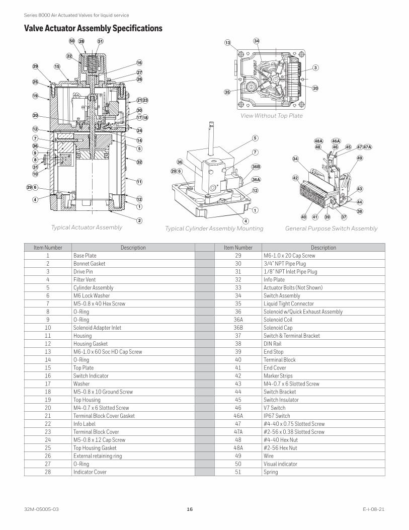
Valve Actuator Assembly Specifications
19
20
7
629
4
2
1
5
14
29
21 23
24
11
12
25
36
17 18
12
32
10
31
9
8
30
2850
15
22
27
26
16
51
48 46 45 47
49
43
34
44
3837394140
42
46A47A
48A
629
1
4
36B
5
7
12
36A
36
35
13
20
34
3
Typical Actuator Assembly Typical Cylinder Assembly Mounting General Purpose Switch Assembly
View Without Top Plate
Item Number Description Item Number Description1 Base Plate 29 M6-1.0 x 20 Cap Screw2 Bonnet Gasket 30 3/4” NPT Pipe Plug3 Drive Pin 31 1/8” NPT Inlet Pipe Plug4 Filter Vent 32 Info Plate5 Cylinder Assembly 33 Actuator Bolts (Not Shown)6 M6 Lock Washer 34 Switch Assembly7 M5-0.8 x 40 Hex Screw 35 Liquid Tight Connector8 O-Ring 36 Solenoid w/Quick Exhaust Assembly9 O-Ring 36A Solenoid Coil
10 Solenoid Adapter Inlet 36B Solenoid Cap11 Housing 37 Switch & Terminal Bracket12 Housing Gasket 38 DIN Rail13 M6-1.0 x 60 Soc HD Cap Screw 39 End Stop14 O-Ring 40 Terminal Block15 Top Plate 41 End Cover16 Switch Indicator 42 Marker Strips17 Washer 43 M4-0.7 x 6 Slotted Screw18 M5-0.8 x 10 Ground Screw 44 Switch Bracket19 Top Housing 45 Switch Insulator20 M4-0.7 x 6 Slotted Screw 46 V7 Switch21 Terminal Block Cover Gasket 46A IP67 Switch22 Info Label 47 #4-40 x 0.75 Slotted Screw23 Terminal Block Cover 47A #2-56 x 0.38 Slotted Screw24 M5-0.8 x 12 Cap Screw 48 #4-40 Hex Nut25 Top Housing Gasket 48A #2-56 Hex Nut26 External retaining ring 49 Wire27 O-Ring 50 Visual indicator28 Indicator Cover 51 Spring
Series 8000 Air Actuated Valves for liquid service
E-i-08-21 17 32M-05005-03
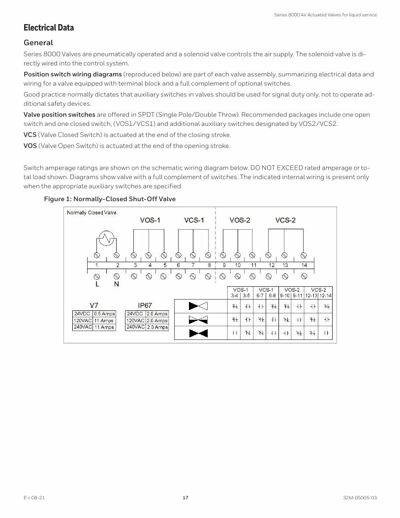
Electrical DataGeneralSeries 8000 Valves are pneumatically operated and a solenoid valve controls the air supply. The solenoid valve is di-rectly wired into the control system.
Position switch wiring diagrams (reproduced below) are part of each valve assembly, summarizing electrical data and wiring for a valve equipped with terminal block and a full complement of optional switches.
Good practice normally dictates that auxiliary switches in valves should be used for signal duty only, not to operate ad-ditional safety devices.
Valve position switches are offered in SPDT (Single Pole/Double Throw). Recommended packages include one open switch and one closed switch, (VOS1/VCS1) and additional auxiliary switches designated by VOS2/VCS2.
VCS (Valve Closed Switch) is actuated at the end of the closing stroke.
VOS (Valve Open Switch) is actuated at the end of the opening stroke.
Switch amperage ratings are shown on the schematic wiring diagram below. DO NOT EXCEED rated amperage or to-tal load shown. Diagrams show valve with a full complement of switches. The indicated internal wiring is present only when the appropriate auxiliary switches are specified.
Figure 1: Normally-Closed Shut-Off Valve

Series 8000 Air Actuated Valves for liquid service
32M-05005-03 18 E-i-08-21
General Purpose - Series 8031 & 8131Solenoid valve power ratings
VoltageAmperage (A) Power
In-Rush Holding In-Rush Holding24VDC 0.20 0.20 4.8 W 4.8 W
120VAC 50 Hz 0.09 0.07 11 VA 8.5 VA120VAC 60 Hz 0.08 0.05 9.4 VA 6.9 VA240VAC 50 Hz 0.05 0.04 11 VA 8.5 VA240VAC 60 Hz 0.04 0.03 9.4 VA 6.9 VA
Standard switch amperage ratings as shown on the valve switch wiring diagramVoltage Maximum Amperage (A)24VDC 0.5
120VAC 50/60 Hz 11240VAC 50/60 Hz 11
Class I, Div . 2 Hazardous Location - Series 8032 & 8132Solenoid valve power ratings
VoltageAmperage (A) Power
In-Rush Holding In-Rush Holding24VDC 0.20 0.20 4.8 W 4.8 W
120VAC 50 Hz 0.09 0.07 11 VA 8.5 VA120VAC 60 Hz 0.08 0.05 9.4 VA 6.9 VA240VAC 50 Hz 0.05 0.04 11 VA 8.5 VA240VAC 60 Hz 0.04 0.03 9.4 VA 6.9 VA
24VDC IS 0.09 0.09 2.1 W 2.1 W
IP67 switch amperage ratings as shown on the valve switch wiring diagramVoltage Maximum Amperage (A)24VDC 2.0
120VAC 50/60 Hz 2.0240VAC 50/60 Hz 2.0

Series 8000 Air Actuated Valves for liquid service
E-i-08-21 19 32M-05005-03
Class I Div . 1 - Series 8033 & 8133The Series 8000 Valve achieves Class I Div.1 hazardous location certification through the Intrinsically Safe (IS) protection method. Below is a representation of the Con-trol Drawing. The MAXON standard offering does not in-clude the barriers/isolators that are depicted below in the non-hazardous location; however, they can be provided as an additional accessory. Consult MAXON for details.
The intrinsic safety and operational criteria for most appli-cations can be met with a 24 VDC supply and the barriers described in the Control Drawing. Specific installations with long cable runs, low power requirements, or other complications may require a barrier with different param-eters.
HAZARDOUS(CLASSIFIED) LOCATION
CLASS I, DIVISION 1, GROUPS A,B,C,D
CLASS II, DIVISION 1, GROUPS E,F,G
CLASS III, DIVISION 1
NON-HAZARDOUS LOCATION
Factory Mutual/CSA Approved Barrier(s) used in an Approved Config. with “V” max. greater than “VI” or“Voc” and “I” max greater than “I t” or “I sc”
PowerSupply
CSA/FM/ATEX certified Barrierrated 28 V max./300 ohms min. or equivalent
250 RMS max.
“CSA/FM/ATEX certified Barrier for a simple apparatus”
Solenoid Entity Parameters V max = 28 VDCI max. = 115 mAPi = 1.6 WCi = 0 µFLi = 0 µH
ValvePosition
Switch
Switch Entity Parameters V max. = 30 VDCI max. = 500 mA Pi = 2 WCi = 0 µF Li = 0 µH
NOTES:
1) The Intrinsic Safety Entity concept allows the intercon-nection of two FM approved (CSA certified when in-stalled in Canada) Intrinsically safe devices with entity parameters not specifically examined in combination as a system when: Voc or Uo or Vt ≤ Vmax, Isc or Io or It ≤ Imax, Ca or Co ≥ Ci+ Ccable, La or Lo ≥ Li + Lcable, and for FM only: Po ≤ Pi.
2) Dust-tight conduit seal must be used when installed in Class II and Class III environments.
3) Control equipment connected to the Associated Appa-ratus must not use or generate more than 250 Vrms or Vdc.
4) Installation in the U.S. should be in accordance with ANSI/ISA RP12.06.01 “Installation of Intrinsically Safe Systems for Hazardous (Classi- fied) Locations” and the National Electrical Code® (ANSI/NFPA 70) Sec-tions 504 and 505.
5) Installation in Canada should be in accordance with the Canadian Electrical Code, CSA C22.1, Part 1, Ap-pendix F.
6) Installation in the European Union should be in ac-cordance to Regulation 2014/34/EU (ATEX). In case the valve and/or its switches have a safety function, the use of fail safe equipment is required.
7) The configuration of associated Apparatus must be FM Approved (CSA certified when in Canada) under Entity Concept.
8) Associated Apparatus manufacturer’s installation drawing must be followed when installing this equip-ment.
9) No revision to drawing without prior authorization from FM Approval and CSA International.

Series 8000 Air Actuated Valves for liquid service
32M-05005-03 20 E-i-08-21
Control drawing for customer-supplied, externally mounted solenoids
Powersupply
see note 3
Factory Mutual/CSA ApprovedBarrier(s) used in an Approved con�guration with "V" max. greater than "Vt" or "Voc" and "I" max. greater than "I t" or "I sc"
HAZARDOUS (CLASSIFIED) LOCATIONCLASS I, DIVISION 1, GROUPS A,B,C,DCLASS II, DIVISION 1, GROUPS E,F,GCLASS III, DIVISION 1
Solenoid Valve
"CSA/FM/ATEX certi�ed Barrier for a simple apparatus"
Switch Entity Parameters
V max.=30 VDCI max.=500 mAPi= 2 WCi= O µFLi= O µH
ValvePosition
Switch
NON-HAZARDOUS LOCATION
Customer Supplied Solenoid Valve-To be mounted external to valve actuator.-Component must be rated for the Class and Division of the hazardous environment as stated above.-Component must be rated for instrinsic safety and be interconnected with other intrinsically safe devices as required under the Intrinsic Safety Entity Concept (see note 1).
NOTES:
1) The Intrinsic Safety Entity concept allows the intercon-nection of two FM approved (CSA Certified when in-stalled in Canada) Intrinsically safe devices with entity parameters not specifically examined in combination as a system when: Voc or Uo or Vt ≤ Vmax, Isc or Io or It ≤ Imax, Ca or Co ≥ Ci+ Ccable, La or Lo ≥ Li + Lcable, and for FM only: Po ≤ Pi.
2) Dust-tight conduit seal must be used when installed in Class II and Class III environments.
3) Control equipment connected to the Associated Ap-paratus must not use or generate more than the maxi-mum permissible safe area voltage (Um) for the barrier.
4) Installation in the U.S. should be in accordance with ANSI/ISA RP12.06.01 “Installation of Intrinsically Safe Systems for Hazardous (Classi- fied) Locations” and the National Electrical Code® (ANSI/NFPA 70) Sec-tions 504 and 505.
5) Installation in Canada should be in accordance with the Canadian Electrical Code, CSA C22.1, Part 1, Ap-pendix F.
6) Installation in the European Union should be in ac-cordance to Regulation 2014/34/EU (ATEX).
7) The configuration of associated Apparatus must be FM Approved (CSA Certified when in Canada) under Entity Concept.
8) Associated Apparatus manufacturer’s installation drawing must be followed when installing this equip-ment.
9) No revision to drawing without prior authorization from FM Approval and CSA International.

Series 8000 Air Actuated Valves for liquid service
E-i-08-21 21 32M-05005-03
To select a different safety barrier, choose a design that limits voltage, current, and power under worst-case fault conditions to values less than the IS entity parameters, while still meeting the minimum operational requirements under worst-case non-fault conditions. The IS entity pa-rameters and operational requirements are listed in the following tables.
The barrier will specify a maximum voltage peak Voc 1, a
maximum short-circuit current, Isc 2 and maximum power
output Po 3. These barrier ratings must be less than or
equal to the IS entity parameters of the field device, i.e., Voc ≤ Vmax, Isc ≤ Imax, and Po ≤ Pi.The barrier will also specify a maximum allowed capacitance Ca and inductance La, which must be greater than or equal to the sum of those of the load device and field wiring, i.e., Ca ≥ Ci + Ccable and La ≥ Li + Lcable.
The solenoid requires a minimum current (Imin) to operate properly. The nominal barrier input voltage (Vworking, as specified by the barrier) must be adequate to provide Imin through the maximum barrier resistance, the maximum wiring resistance, the resistance of any fuses, and the maximum solenoid resistance (Ri).
NOTE: Vworking will always be less than Vmax or Voc . Never intentionally supply Voc to the barrier, as this could blow an internal fuse and ruin the barrier .
1 The maximum voltage possible at the barrier input or output under a no-load condition.
2 Found when the barrier input is at Voc and a short-circuit appears on the barrier output.
3 Found when the barrier input is at Voc and a matched load appears on the barrier output. Note that this value is the transmitted power, and does not include the power dissipated by the barrier itself.

Series 8000 Air Actuated Valves for liquid service
32M-05005-03 22 E-i-08-21
Barrier selection criteria for solenoidIS entity parameters 1
Maximum voltage input (Vmax) 28 V 2
Maximum current input (Imax) 115 mAMaximum power input (Pi) 1.6 WInternal capacitance (Ci) 0 µFInternal inductance (Li) 0 µH
Operational ParametersMinimum operational current (Imin) 37 mA
Solenoid internal resistance (Ri) 275 ohms ± 8%
Barrier selection criteria for switchIS entity parameters (simple apparatus)
Maximum voltage input (Vmax) 30 V 3
Maximum current input (Imax) 500 mA 3
Maximum power input (Pi) 1.3 W 4
Internal capacitance (Ci) 0 µFInternal inductance (Li) 0 µH
Operational ParametersMinimum operational current (Imin) Application specific
Switch internal on-resistance (Ri) < 1 ohm
1 Obtained from the manufacturer’s published entity parameters.
2 Never intentionally supply Vmax to the barrier, as this could blow an internal fuse and ruin the barrier.
3 Obtained from the switch’s safety ratings.4 Standard Pi for a simple apparatus.
Series 8000 Air Actuated Valves for liquid service
E-i-08-21 23 32M-05005-03
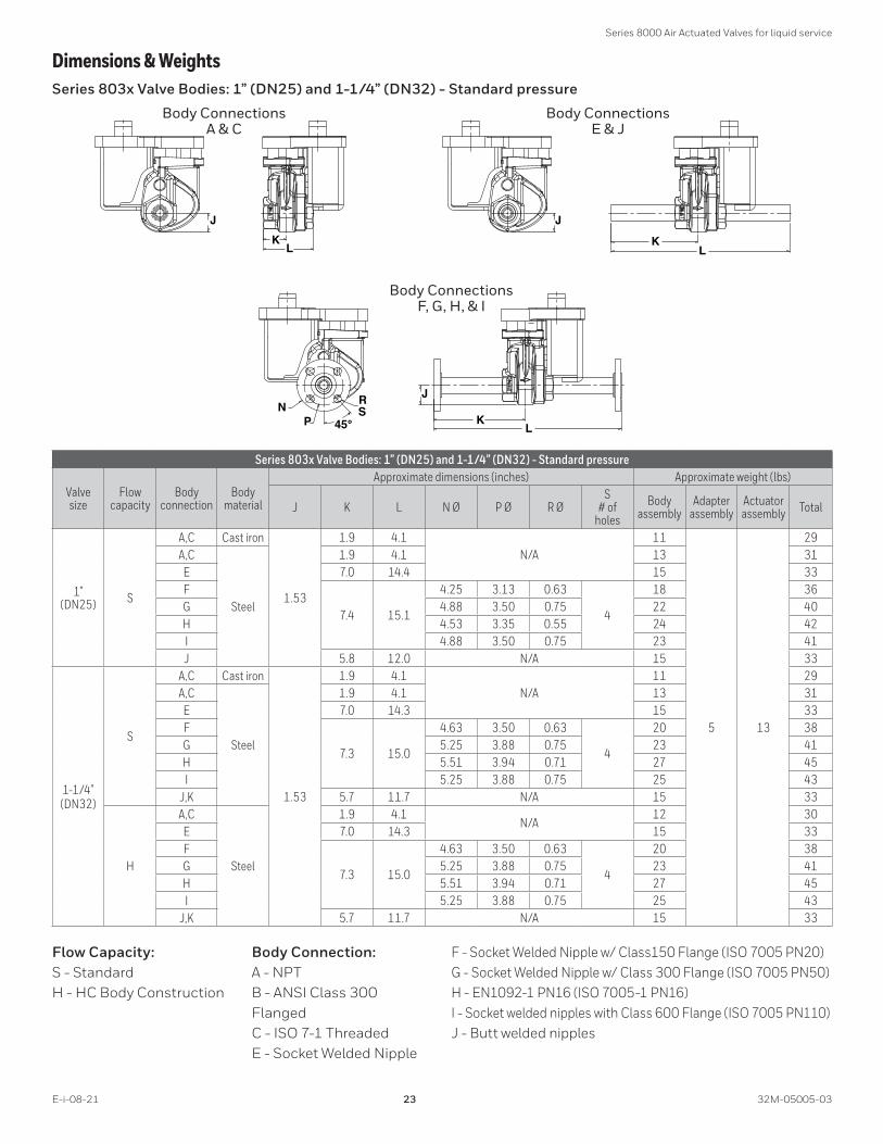
Dimensions & WeightsSeries 803x Valve Bodies: 1” (DN25) and 1-1/4” (DN32) - Standard pressure
JK
L
J
JN
P
RS
45° KL
KL
Body Connections A & C
Body Connections E & J
Body Connections F, G, H, & I
Series 803x Valve Bodies: 1” (DN25) and 1-1/4” (DN32) - Standard pressure
Valve size
Flow capacity
Body connection
Body material
Approximate dimensions (inches) Approximate weight (lbs)
J K L N Ø P Ø R ØS
# of holes
Body assembly
Adapter assembly
Actuator assembly Total
1” (DN25) S
A,C Cast iron
1.53
1.9 4.1N/A
11
5 13
29A,C
Steel
1.9 4.1 13 31E 7.0 14.4 15 33F
7.4 15.1
4.25 3.13 0.63
4
18 36G 4.88 3.50 0.75 22 40H 4.53 3.35 0.55 24 42I 4.88 3.50 0.75 23 41J 5.8 12.0 N/A 15 33
1-1/4”(DN32)
S
A,C Cast iron
1.53
1.9 4.1N/A
11 29A,C
Steel
1.9 4.1 13 31E 7.0 14.3 15 33F
7.3 15.0
4.63 3.50 0.63
4
20 38G 5.25 3.88 0.75 23 41H 5.51 3.94 0.71 27 45I 5.25 3.88 0.75 25 43
J,K 5.7 11.7 N/A 15 33
H
A,C
Steel
1.9 4.1N/A
12 30E 7.0 14.3 15 33F
7.3 15.0
4.63 3.50 0.63
4
20 38G 5.25 3.88 0.75 23 41H 5.51 3.94 0.71 27 45I 5.25 3.88 0.75 25 43
J,K 5.7 11.7 N/A 15 33
Flow Capacity:S - Standard H - HC Body Construction
Body Connection:A - NPT B - ANSI Class 300 Flanged C - ISO 7-1 Threaded E - Socket Welded Nipple
F - Socket Welded Nipple w/ Class150 Flange (ISO 7005 PN20) G - Socket Welded Nipple w/ Class 300 Flange (ISO 7005 PN50) H - EN1092-1 PN16 (ISO 7005-1 PN16) I - Socket welded nipples with Class 600 Flange (ISO 7005 PN110) J - Butt welded nipples

Series 8000 Air Actuated Valves for liquid service
32M-05005-03 24 E-i-08-21
Series 803x Valve Actuators: 1” (DN25) and 1-1/4” (DN32) - Standard pressure
1) 1/8” NPT (DN6) air inlet connection2) Visual indication of valve3) Air exhaust - do not block4) 2x 3/4” (DN20) NPT conduit connec
tion
3
AB
C
DEF
G
HH
1
2
4
Valve size
Approximate dimensions (inches)
A B C D E F G HClearance needed to remove 1
1” (DN25)
3.7 2.8 12 2.6 2.9 2.5 18.2 2.5 211-1/4” (DN32)
1 From pipe center line

Series 8000 Air Actuated Valves for liquid service
E-i-08-21 25 32M-05005-03
Series 813x Valve Bodies: 3/8” (DN10) to 1-1/4” (DN32) - High pressure bodies
JK
L
J
KL
NP 45°
R S
J
KL
Body Connections A & C
Body Connections E & J
Body Connections F, G, H, & I
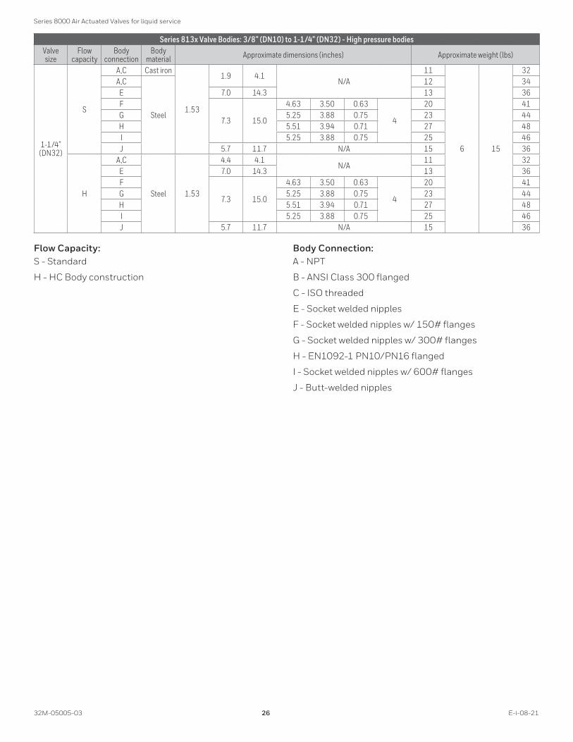
Series 813x Valve Bodies: 3/8” (DN10) to 1-1/4” (DN32) - High pressure bodies
Valve size
Flow capacity Body Body
material
Approximate dimensions (inches) Approximate weight (lbs)
J K L N Ø P Ø R ØS
# of holes
Body assembly
Adapter assembly
Actuator assembly Total
3/8” (DN10) S A,C Cast iron 1.2 1.5 3.2 N/A 11
5 13
29
1/2” (DN15) S
A,C Cast iron
1.2
1.5 3.2N/A
11 29A,C
Steel
12 30E 6.6 13.5 13 31F
7.0 14.3
3.50 2.380.63
4
15 33G 3.75 2.63 17 35H 3.74 2.56 0.55 20 38I 3.75 2.63 0.63 19 37J 5.5 11.3 N/A 13 31
3/4” (DN20) S
A,C Cast iron
1.2
1.5 3.2N/A
11 29A,C
Steel
12 30E 6.6 13.4 13 31F
9.1 14.2
3.88 2.75 0.63
4
15 33G 4.63 3.25 0.75 17 35H 4.13 2.95 0.55 21 39I 4.63 3.25 0.75 20 38J 5.4 11.0 N/A 13 31
1” (DN25) S
A,C Cast iron
1.53
1.9 4.1N/A
11
6 15
32A,C
Steel
12 34E 7.0 14.4 13 36F
7.4 15.1
4.25 3.13 0.63
4
18 39G 4.88 3.50 0.75 22 43H 4.53 3.35 0.55 24 45I 4.88 3.50 0.75 23 44J 5.8 12.0 N/A 15 36
Series 8000 Air Actuated Valves for liquid service
32M-05005-03 26 E-i-08-21
Series 813x Valve Bodies: 3/8” (DN10) to 1-1/4” (DN32) - High pressure bodiesValve size
Flow capacity
Body connection
Body material Approximate dimensions (inches) Approximate weight (lbs)
1-1/4” (DN32)
S
A,C Cast iron
1.53
1.9 4.1N/A
11
6 15
32A,C
Steel
12 34E 7.0 14.3 13 36F
7.3 15.0
4.63 3.50 0.63
4
20 41G 5.25 3.88 0.75 23 44H 5.51 3.94 0.71 27 48I 5.25 3.88 0.75 25 46J 5.7 11.7 N/A 15 36
H
A,C
Steel 1.53
4.4 4.1N/A
11 32E 7.0 14.3 13 36F
7.3 15.0
4.63 3.50 0.63
4
20 41G 5.25 3.88 0.75 23 44H 5.51 3.94 0.71 27 48I 5.25 3.88 0.75 25 46J 5.7 11.7 N/A 15 36
Flow Capacity:S - Standard
H - HC Body construction
Body Connection:A - NPT
B - ANSI Class 300 flanged
C - ISO threaded
E - Socket welded nipples
F - Socket welded nipples w/ 150# flanges
G - Socket welded nipples w/ 300# flanges
H - EN1092-1 PN10/PN16 flanged
I - Socket welded nipples w/ 600# flanges
J - Butt-welded nipples
Series 8000 Air Actuated Valves for liquid service
E-i-08-21 27 32M-05005-03
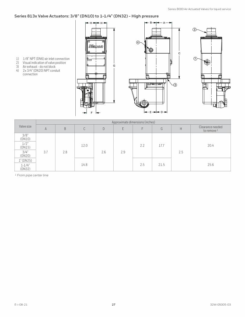
Series 813x Valve Actuators: 3/8” (DN10) to 1-1/4” (DN32) - High pressure
1) 1/8” NPT (DN6) air inlet connection2) Visual indication of valve position3) Air exhaust - do not block4) 2x 3/4” (DN20) NPT conduit
connection
1
2
3
4
H H B A
E D
C
G
F
Valve sizeApproximate dimensions (inches)
A B C D E F G H Clearance needed to remove 1
3/8” (DN10)
3.7 2.8
12.0
2.6 2.9
2.2 17.7
2.5
20.41/2” (DN15)
3/4” (DN20)
1” (DN25)14.8 2.5 21.5 25.61-1/4”
(DN32) 1 From pipe center line

Series 8000 Air Actuated Valves for liquid service
32M-05005-03 28 E-i-08-21
Minimum required cylinder pressures
0102030405060708090100
0 100 200 300 400
1"1.25"1.25"HC
Pressure Required to Actuator Series 8000: 1" - 1-1/4"
Group 1 Liquids
Application Fluid Pressure (psi)
Act
uato
r Pre
ssur
e R
equi
red
(psi
)
0102030405060708090100
0 150 300 450 600 740
.375" .5"
.75" 1"
1.25" 1.25"HC
Pressure Required to ActuatorSeries 8100: 3/8" - 1-1/4"
Group 1 Liquids
Application Fluid Pressure (psi)
Act
uato
r Pre
ssur
e R
equi
red
(psi
)
Group 1 fluids include: JP4, Kerosene, No. 1 Fuel oil, No. 2 Fuel oil, and Ammonia

Series 8000 Air Actuated Valves for liquid service
E-i-08-21 29 32M-05005-03
0102030405060708090100
0 100 200 300 400
1"1.25"1.25"HC
Pressure Required to Actuator Series 8000: 1" - 1-1/4"
Group 2 Liquids
Application Fluid Pressure (psi)
Act
uato
r Pre
ssur
e R
equi
red
(psi
)
0102030405060708090100
0 150 300 450 600 740
.375" .5"
.75" 1"
1.25" 1.25"HC
Pressure Required to ActuatorSeries 8100: 3/8" - 1-1/4"
Group 2 Liquids
Application Fluid Pressure (psi)
Act
uato
r Pre
ssur
e R
equi
red
(psi
)
Group 2 fluids include: No. 4 fuel oil, No. 5 fuel oil, and No.6 fuel oil

Series 8000 Air Actuated Valves for liquid service
32M-05005-03 30 E-i-08-21
0102030405060708090100
0 100 200 300 400
1"1.25"1.25"HC
Pressure Required to Actuator Series 8000: 1" - 1-1/4"
Group 3 Liquids
Application Fluid Pressure (psi)
Act
uato
r Pre
ssur
e R
equi
red
(psi
)
0102030405060708090100
0 150 300 450 600 740
.375" .5"
.75" 1"
1.25" 1.25"HC
Pressure Required to ActuatorSeries 8100: 3/8" - 1-1/4"
Group 3 Liquids
Application Fluid Pressure (psi)
Act
uato
r Pre
ssur
e R
equi
red
(psi
)
Group 3 fluids include: Liquid Ethanol, Liquid Methanol, No. 6 Fuel oil (heavy), Liquid Butane and Liquid Propane

Series 8000 Air Actuated Valves for liquid service
E-i-08-21 31 32M-05005-03
0102030405060708090100
0 100 200 300 400
1"1.25"1.25"HC
Actu
ator
Pre
ssur
e R
equi
red
(psi
)
Application Fluid Pressure (psi)
Pressure Required to ActuatorSeries 8000: 1" - 1-1/4"
Group 4 Liquids
0102030405060708090
0 150 300 450 600 740
.375" .5"
.75" 1"1.25"HC1.25"
Act
uato
r Pr
essu
re R
equi
red
(psi
)
Application Fluid Pressure (psi)
Pressure Required to ActuatorSeries 8100: 3/8"
Group 4 Liquids- 1-1/4"
Group 4 fluids include: Residual fuel oil and Steam
Series 8000 Air Actuated Valves for liquid service
32M-05005-03 32 E-i-08-21
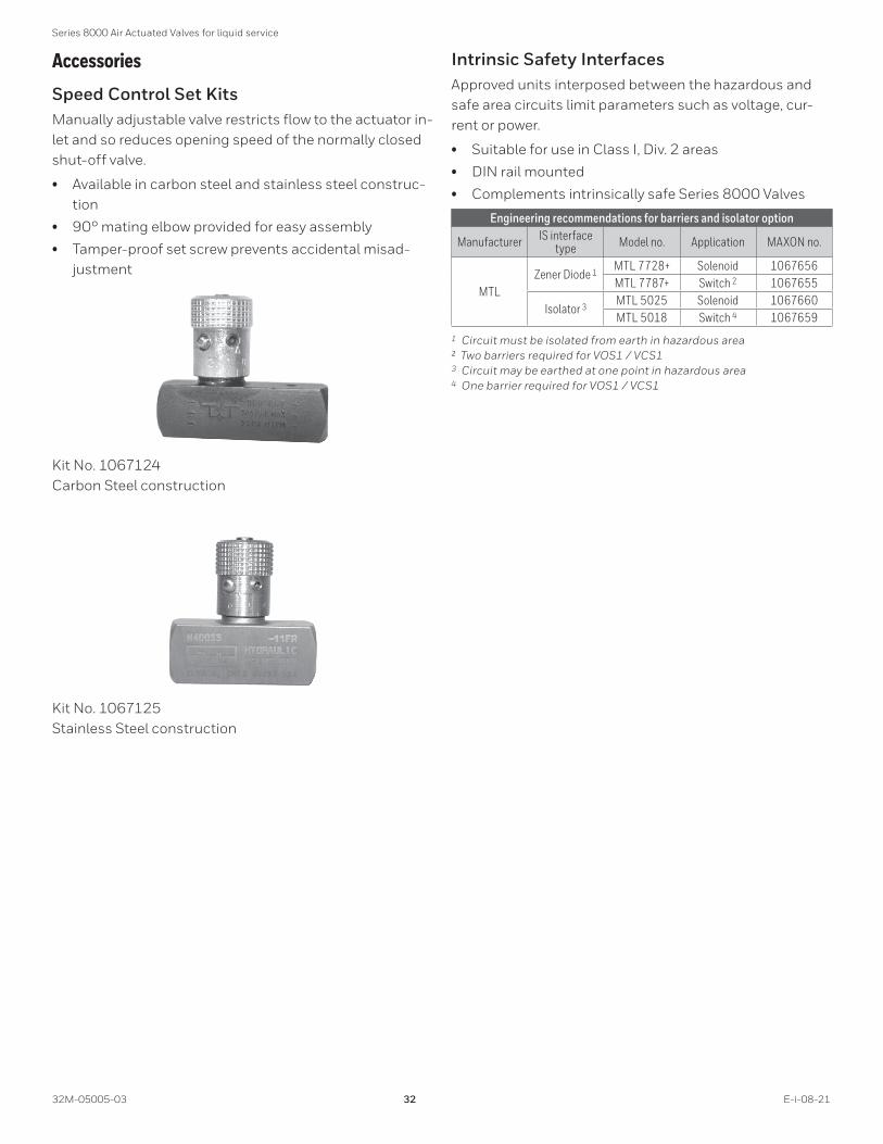
AccessoriesSpeed Control Set KitsManually adjustable valve restricts flow to the actuator in-let and so reduces opening speed of the normally closed shut-off valve.
• Available in carbon steel and stainless steel construc-tion
• 90° mating elbow provided for easy assembly
• Tamper-proof set screw prevents accidental misad-justment
Kit No. 1067124 Carbon Steel construction
Kit No. 1067125 Stainless Steel construction
Intrinsic Safety InterfacesApproved units interposed between the hazardous and safe area circuits limit parameters such as voltage, cur-rent or power.
• Suitable for use in Class I, Div. 2 areas
• DIN rail mounted
• Complements intrinsically safe Series 8000 Valves
Engineering recommendations for barriers and isolator option
Manufacturer IS interface type Model no. Application MAXON no.
MTLZener Diode 1 MTL 7728+ Solenoid 1067656
MTL 7787+ Switch 2 1067655
Isolator 3 MTL 5025 Solenoid 1067660MTL 5018 Switch 4 1067659
1 Circuit must be isolated from earth in hazardous area ² Two barriers required for VOS1 / VCS13 Circuit may be earthed at one point in hazardous area 4 One barrier required for VOS1 / VCS1

Series 8000 Air Actuated Valves for liquid service
E-i-08-21 33 32M-05005-03
INSTALLATION, OPERATION AND MAINTENANCE INSTRUCTIONS^ Please read the operating and mounting instruc-
tions before using the equipment. Install the equipment in compliance with the prevailing regulations.
^ Bedrijfs- en montagehandleiding voor gebruik goed lezen! Apparaat moet volgens de geldende voorschriften worden geïnstalleerd.
^ Lire les instructions de montage et de service avant utilisation! L’appareil doit imperativement être installé selon les règlementations en vigueur.
^ Betriebs- und Montageanleitung vor Gebrauch lesen! Gerät muß nach den geltenden Vorschrif-ten installiert werden.
European Sales Office
BELGIUM
MAXON International BVBA Luchthavenlaan 16-18
1800 Vilvoorde, Belgium
Tel: 32.2.255.09.09
Fax: 32.2.251.82.41
The Installation, Operating and Maintenance Instructions contain important information that must be read and followed by anyone operat-ing or servicing this product . Do not operate or service this equipment unless the instructions have been read . IMPROPER INSTALLATION OR USE OF THIS PRODUCT COULD RESULT IN BODILY INJURY OR DEATH .
DescriptionThe Series 8000 Valve is a pneumatically operated fuel shut-off valve. These valves require compressed air for actuation. The 8000 Series Valve will open by the addi-tion of a control voltage signal. Removal of the signal will cause a fast acting return to the closed position.
The Series 8000 Valve has optional configurations that meet hazardous locations.
Nameplate and AbbreviationsConsult the nameplate on your valve. This lists the maxi-mum operating pressure, temperature limitations, volt-age requirements and service conditions of your specific valve. Do not exceed nameplate ratings.
Abbreviation or Symbol Description
M.O.P. Maximum Operating PressurePACT Required actuator pressureTAMB Ambient temperature rangeTFL Fluid temperature range
Visual indication determined by text, color and symbol; valve is shown in open position
Visual indication determined by text, color and symbol; valve is shown in closed position
Valve is shut
Valve is partially open
Valve is full open
VOS-1/2 Valve open switch(es)VCS-1/2 Valve closed switch(es); proof of closure

Series 8000 Air Actuated Valves for liquid service
32M-05005-03 34 E-i-08-21
Component identification
2
9
10
6
7 1
8
4
5
3
11
1) Flow arrow2) Visual indication3) Terminal block cover screws, M5 x 124) Switch access cover5) Terminal block cover6) Actuator bolts, M10 x 50 - M10 x 62 or M10 x 357) Valve body8) Actuator9) Switch access cover screws, M6 x 2010) Nameplate11) Nameplate screws, M4 x 6

Series 8000 Air Actuated Valves for liquid service
E-i-08-21 35 32M-05005-03
Installation1. A filter or strainer of 40 mesh (0.6 mm maximum) or
greater is recommended in the fuel piping to protect the downstream safety shut-off valves.
2. Properly support and pipe the valve in the direction of the flow arrow on the valve body. Valve seats are di-rectional. Sealing will be maintained at full rated pres-sures in one direction only. Sealing will be provided in reverse flow only at reduced pressures.
3. Mount valve so that open/shut indicator will not face downward.
4. Series 8000 Valves require clean, dry compressed air or gas piped to the inlet of the actuator. Guidelines for various actuating gases:
A. Compressed Air
1. The vent, located on the underside of the base plate, should be protected from blockage.
2. Although MAXON Series 8000 Valves do not require lubrication, they do contain Buna-N (-40°F) seals in the actuator sub-assembly. Compressed air supply must not contain any lubricant that is not compatible with Buna-N elastomers.
B. Natural gas and other fuel gases can be used to actuate the Series 8000 Valve when the appropriate considerations are taken into account.
1. Apply only the intrinsically safe Series 8000 Valve for the application. The general purpose and non-incendive options are not suitable for fuel gas activation.
2. The activating fuel gas must be clean and free of moisture. The Series 8000 actuator contains Buna-N elastomers and brass components that will come in contact with the activating gas. The quality of the gas must not contain any con-stituents that are not compatible with Buna-N or brass.
3. The exhaust gas must be vented to the at-mosphere in a safe manner by piping from the filtered vent, located on the underside of the ac-tuator’s base. A 1/8” NPT female connection in the base plate allows for proper piping.
4. The use of fuel gases for actuation is not permit-ted in EC areas due to ATEX Zone 2 restrictions.
5. Actuators for fuel gas activation are only rated from -40°F to 140°F
5. In some instances, it may be desired to utilize a slow opening feature for either application or code-related reasons. If a slow opening feature is required for nor-
mally closed shut-off valves, use MAXON’s optional speed control set kit.
6. Wire the valve in accordance with all applicable local and national codes and standards. In U.S. and Canada, wiring must conform to the NEC ANSI/NFPA 70 and/or CSA C22.1, Part 1.
A. Supply voltages must agree with valve’s nameplate voltage within -15%/+10% for proper operation. For electrical wiring schematic, see instructions or sam-ple affixed inside valve terminal block cover.
B. Grounding is achieved with a grounding screw, which is located in the top assembly.
C. Customer connections are provided via terminal block located in the top assembly.
D. Main power wiring (120 VAC or 240 VAC) must be segregated from lower voltage 24 VDC signal wiring, when both are required.
WARNING: For Division 2 installations using the intrinsically safe solenoid, the power source is not to exceed 28VDC with a minimum series resistance of 300 ohms.
7. Maintain integrity of the Series 8000 actuator enclo-sure by using the appropriate electrical connectors for the (2) 3/4” NPT conduit threaded connections.The Series 8000 electrical enclosure is NEMA 4 and IP65 rated with an option for NEMA 4X.
8. All access cover plate screws should be tightened us-ing an alternate cross-corner tightening pattern to the values shown in Table 1 below.
Table 1 - Torque SpecificationsItem Number Description Torque
3 Terminal Block Cover Screws, M5 x 12 20 in-lbs9 Switch Access Cover Screws, M6 x 20 20 in-lbs6 Actuator Bolts, M10 x 50 - M10 x 62 13 ft-lbs6 Actuator Bolts, M10 x 35 13 ft-lbs
11 Nameplate Screws, M4 x 6 10 in-lbs
9. Verify proper installation and operation by electrically actuating the valve for 10-15 cycles prior to the first introduction of liquid.
10. When customer-supplied, externally mounted sole-noids are used, the component must be rated for the Class and Division of the hazardous area. MAXON 8032 and 8132 valve will only carry FM Approval to FM 3611, 3600 and 3810 standards. MAXON 8033 and 8133 valves will only carry FM Approval to FM 3610, 3600 and 3810 standards.

Series 8000 Air Actuated Valves for liquid service
32M-05005-03 36 E-i-08-21
Operating characteristics• Opening time varies per valve size, 3 seconds or less for largest size. For slower opening, a speed control set can be
supplied by MAXON.
• Closing time is less than 1 second.
• Type of medium 4,5
Media compatibility and valve approval certifications
Media Media Code
Suggested Material OptionsMOPD
Rating4 5
Agency Approvals and CertificationsBody Seals & Stem packing Body Material Internal Trim FM CSA7 ATEX
Ammonia (anhydrous) AMMA C,D 1,2 D Std. X X XEthanol (liquid) ETHL A,C,D 2 D,P Note2 X X X
JP4 JP4 A,B,D 1,2 B,D Std. X X XKerosene KERO A,B,D 1,2 B,D Std. X X X
Methanol (liquid) METHL A,C,D 1,2 B,D,P Note2 X X XNo. 1 Fuel Oil NO1OIL A,B,D 1,2 B,D Std. X X XNo. 2 Fuel Oil NO2OIL A,B,D 1,2 B,D Std. X X X
No. 4 Fuel Oil (125 SSU max) 6 NO4OIL A,B,D 1,2 B,D Note1 X X XNo. 5 Fuel Oil (900 SSU max) 6 NO5OIL A,B,D 1,2 B,D Note1 X X X
No. 6 Fuel Oil (2500 SSU max) 6 NO6OIL A,B,D 1,2 B,D Note1 X X XNo. 6 Fuel Oil (7000 SSU max) 6 NO6OILH A,B,D 1,2 B,D Note2 X X XResidual oil (15000 SSU max) 6 RESID A,B,D 1,2 B,D Note3 X X X
Butane (liquid) BUTL A,D 2 B,D,P Note2 X X XPropane (liquid) PROPL A,D 2 B,D,P Note2 X X X
Steam STEAM D 1,2 B,D,P Note3 X X X1 Group 2 fluid MOPD ratings are typically 5% lower than standard MOPD ratings
(refer to chart on page 8 (Maximum operating pressure ratings))2 Group 3 fluid MOPD ratings are typically 30% lower than standard MOPD ratings
(refer to chart on page 8 (Maximum operating pressure ratings))3 Group 4 fluid MOPD ratings are typically 40% lower than standard MOPD ratings
(refer to chart on page 8 (Maximum operating pressure ratings))4 MOPD ratings for fuel oils are based on a viscosity of 150 SSU or less. Higher viscosities may result in further reductions to MOPD ratings.
Contact MAXON for details.5 For elevated fluid temperatures, the MOPD is to be reduced in accordance to the applicable piping standard(s).6 Indicated SSU maximum is based on 100°F standard.7 CSA certification does NOT apply if the body connections are either ISO threaded or EN1092 flanged.
Body Seals & Packing: A - Buna-N w/ PTFE
B - Viton™ w/ PTFE
C - Ethylene-Polypropylene w/ PTFE
D - Kalrez® w/ Grafoil®
Body Material: 1 - Cast Iron
2 - Cast Steel
Internal Trim PackageB - Ductile
D - Stellite
P - PEEK
Auxiliary Features• Non-adjustable Proof of Closure Switch(es) with valve
seal over travel interlock.
• Auxiliary switch for indication of full travel (open for normally closed valves).
Operating Environment• Fluid temperature range of -40°F to 550°F .
• Actuators are rated for NEMA 4, IP65 or optional NEMA 4X, IP65.
• Ambient temperature range of -40°F to 140°F for the 8031 and 8131 General Purpose and 8032 and 8132 Non-Incendive series valves.
• Ambient temperature range of -40°F to 122°F for 8033 and 8133 Intrinsically Safe series valves.

Series 8000 Air Actuated Valves for liquid service
E-i-08-21 37 32M-05005-03
Electrical DataNormally-Closed Shut-Off Valves
General Purpose Normally-Closed ValvesSeries 8031 & Series 8131
Switches: V7
Solenoid Valve: Standard 24 VDC, 4.8W, 120VAC, 50/60 Hz, 11/9.4 VA Peak, 8.5/6.9 VA Holding, 240VAC, 50/60 Hz, 11/9.4 VA Peak, 8.5/6.9 VA Holding, See catalog page 17 (Figure 1: Normally-Closed Shut-Off Valve) or inside valve cover for wiring schematic.
Class I, Div . 2 Hazardous Location Normally-Closed ValvesSeries 8032 & Series 8132
Switches: IP67
Solenoid Valve: Standard 24 VDC, 4.8W, 120VAC, 50/60 Hz, 11/9.4 VA Peak, 8.5/6.9 VA Holding, 240VAC, 50/60 Hz, 11/9.4 VA Peak, 8.5/6.9 VA Holding, 24VDC IS, 0.09W
Class I, Div . 1 and ATEX Zone 1 Intrinsically Safe Hazardous Location Normally-Closed ValvesSeries 8033 & Series 8133
Switches: V7 with optional IP67
Solenoid Valve: Intrinsically Safe
NOTES:
1) The Intrinsic Safety Entity concept allows the intercon-nection of two FM approved (CSA certified when in-stalled in Canada) intrinsically safe devices with entity parameters not specifically examined in combination as a system when: Voc or Uo or Vt ≤Vmax, Isc or Io or It ≤ Imax, Ca or Co ≥ Ci+ Ccable, La or Lo ≥ Li + Lcable, and for FM only: Po ≤ Pi.
2) Dust-tight conduit seal must be used when installed in Class II and Class III environments.
3) Control equipment connected to the Associated Appa-ratus must not use or generate more than 250 Vrms or Vdc.
4) Installation in the U.S. should be in accordance with ANSI/ISA RP12.06.01 “Installation of Intrinsically Safe Systems for Hazardous (Classified) Locations” and the National Electrical Code® (ANSI/NFPA 70) Sections 504 and 505.
5) Installation in Canada should be in accordance with the Canadian Electrical Code, CSA C22.1, Part 1, Ap-pendix F.
6) Installation in the European Union should be in ac-cordance to Regulation 2014/34/EU (ATEX). In case the valve and/or its switches have a safety function, the use of fail safe equipment is required.
7) The configuration of associated Apparatus must be FM approved (CSA certified when in Canada) under Entity Concept.
8) Associated Apparatus manufacturer’s installation drawing must be followed when installing this equip-ment.
9) No revision to drawing without prior authorization from FM Approval and CSA International.
HAZARDOUS(CLASSIFIED) LOCATION
CLASS I, DIVISION 1, GROUPS A,B,C,D
CLASS II, DIVISION 1, GROUPS E,F,G
CLASS III, DIVISION 1
NON-HAZARDOUS LOCATION
Factory Mutual/CSA Approved Barrier(s) used in an Approved Config. with “V” max. greater than “VI” or“Voc” and “I” max greater than “I t” or “I sc”
PowerSupply
CSA/FM/ATEX certified Barrierrated 28 V max./300 ohms min. or equivalent
250 RMS max.
“CSA/FM/ATEX certified Barrier for a simple apparatus”
Solenoid Entity Parameters V max = 28 VDCI max. = 115 mAPi = 1.6 WCi = 0 µFLi = 0 µH
ValvePosition
Switch
Switch Entity Parameters V max. = 30 VDCI max. = 500 mA Pi = 2 WCi = 0 µF Li = 0 µH

Series 8000 Air Actuated Valves for liquid service
32M-05005-03 38 E-i-08-21
Class I, Div . 1 and ATEX Zone 1 Intrinsically Safe Hazardous Location Normally-Closed Valves
Series 8033 & Series 8133
Switches: V7 with optional IP67
Solenoid Valve: Customer-supplied, externally mounted
NOTES:
1) The Intrinsic Safety Entity concept allows the intercon-nection of two FM approved (CSA Certified when in-stalled in Canada) Intrinsically safe devices with entity parameters not specifically examined in combination as a system when: Voc or Uo or Vt ≤Vmax, Isc or Io or It ≤ Imax, Ca or Co ≥ Ci+ Ccable, La or Lo ≥ Li + Lcable, and for FM only: Po ≤ Pi.
2) Dust-tight conduit seal must be used when installed in Class II and Class III environments.
3) Control equipment connected to the Associated Ap-paratus must not use or generate more than the maxi-mum permissible safe area voltage (Um) for the barrier.
4) Installation in the U.S. should be in accordance with ANSI/ISA RP12.06.01 “Installation of Intrinsically Safe Systems for Hazardous (Classified) Locations” and the National Electrical Code® (ANSI/ NFPA 70) Sections 504 and 505.
5) Installation in Canada should be in accordance with the Canadian Electrical Code, CSA C22.1, Part 1, Ap-pendix F.
6) Installation in the European Union should be in ac-cordance to Regulation 2014/34/EU (ATEX).
7) The configuration of associated Apparatus must be FM Approved (CSA Certified when in Canada) under Entity Concept.
8) Associated Apparatus manufacturer’s installation drawing must be followed when installing this equip-ment.
9) No revision to drawing without prior authorization from FM Approval and CSA International.
Powersupply
see note 3
Factory Mutual/CSA ApprovedBarrier(s) used in an Approved con�guration with "V" max. greater than "Vt" or "Voc" and "I" max. greater than "I t" or "I sc"
HAZARDOUS (CLASSIFIED) LOCATIONCLASS I, DIVISION 1, GROUPS A,B,C,DCLASS II, DIVISION 1, GROUPS E,F,GCLASS III, DIVISION 1
Solenoid Valve
"CSA/FM/ATEX certi�ed Barrier for a simple apparatus"
Switch Entity Parameters
V max.=30 VDCI max.=500 mAPi= 2 WCi= O µFLi= O µH
ValvePosition
Switch
NON-HAZARDOUS LOCATION
Customer Supplied Solenoid Valve-To be mounted external to valve actuator.-Component must be rated for the Class and Division of the hazardous environment as stated above.-Component must be rated for instrinsic safety and be interconnected with other intrinsically safe devices as required under the Intrinsic Safety Entity Concept (see note 1).

Series 8000 Air Actuated Valves for liquid service
E-i-08-21 39 32M-05005-03
Actuator Assembly Rotation/Replacement MAXON Series 8000 Valves should be ordered
in a configuration compatible with planned pip- ing . If valve orientation is not correct, the actua-tor assembly can be rotated in 90° increments around the valve body center line axis using the procedure below . This procedure should also be followed for field replacement of the actuator .
• Shut off all electrical power and close off upstream manual cock.
• Remove terminal block access cover plate {5} and disconnect power lead wires. Caution: Label all wires prior to disconnec- tion when servicing valve. Wiring errors can cause improper and dangerous operation.
• Remove conduit and electrical leads.
• Remove all pneumatic lines.
• Remove front lower cover from adapter base assembly.
• Unscrew the actuator/adapter bolts {6} screwed up from the bottom. These bolts secure the valve actuator {8} to the adapter base {7}.
• Gently lift the actuator {8} off adapter base assembly enough to break the seal between body assembly and the rubber gas- ket adhering to the bottom of the ac-tuator base plate.
• For assembly rotation: Carefully rotate actuator assembly to the desired po-sition. Reposition the actuator back down onto the adapter base assembly.
• For assembly replacement: Carefully lift the actuator over the spring, which is part of the adapter base assembly. Position the new actuator over the spring and then carefully lower it back onto the adapter base assembly.
• Realign holes in adapter base casting with the cor-responding tapped holes in the bottom of the actuator base plate. Be sure the gasket is still in place between the adapter and actuator base plate.
• Reinsert the adapter bolts up from the bottom through the adapter and carefully engage threads of the actuator assembly. Tighten securely referring to Table 1 for appropriate torque specifications, see page 35 (Table 1 - Torque Specifications) .
• Reconnect conduit, electrical leads, and all pneu-matic lines, then check that signal switch wands are properly positioned. Failure to correct any such misalignment can result in extensive damage to the internal mechanism of your valve.
• Energize valve and cycle several times from closed to full open position. Also electrically trip the valve in a partially opened position to prove valve operates prop-erly.
• Replace and secure all cover plates. Refer to torque values shown on page 35 (Table 1 - Torque Specifi-cations).
• Verify proper operation after servicing.

Series 8000 Air Actuated Valves for liquid service
32M-05005-03 40 E-i-08-21
2
9
3
6
7 1
8
4
5
1) Flow arrow on valve body2) Open/shut indicator 1
3) Name plate4) Switch access cover5) Terminal block cover and screws6) Actuator/body bolts7) Valve body8) Actuator assembly9) Switch access cover screws
1 Open/shut indication is 360°. If required, the observation window may be cleaned with a damp cloth.

Series 8000 Air Actuated Valves for liquid service
E-i-08-21 41 32M-05005-03
Field Installation of Valve Position Switch Instructions below are written for normally-
closed shut-off valves .
General: Shut off fuel supply upstream of valve, then de-energize valve electrically.
Remove top cover and terminal block cover to provide ac-cess (see page 34 (Component identification), items 4 & 5), being careful not to damage gasket.
See pages 41 (Replacement Switches) and 41 (Add Switches) for instructions on adding or replacing switch-es.
Substitution of components may affect suitability for Hazardous Locations.
Field Replacement Items• Position Switches
• Actuators
• Solenoids
Contact MAXON with valve serial numbers to locate ap-propriate switch kit assembly.
Figure 1: Typical Switch Sub-Assembly
Replacement Switches• Carefully remove field wiring from the terminal block.
Insure field wires are clearly marked to correct termi-nal.
• Unwire the solenoid valve lead wires from terminals la-beled #1 and #2.
• Remove screws that secure the switch sub-assembly to the actuator housing. The switch sub-assembly should be easily removable from actuator assembly (see on page 41 (Figure 1: Typical Switch Sub-As-sembly)).
• Note wand position and mounting hole location. Care-fully remove the 2 screws and lift existing switch. Reference Figures 2 through 5 (page 10-30.4-45) to ensure correct switch location.
• Install replacement switch in same mounting holes on bracket and verify correct wand position.
• Replace existing wiring one connection at a time, fol-lowing original route and placement.
• Reassemble switch sub-assembly in actuator housing. Dowel pins are provided to insure proper placement of switch sub- assembly.
• Wire the solenoid valve leads to terminals labeled #1 and #2.
• Cycle valve, checking switch actuation points carefully. VCS switch actuates at top of stem stroke and VOS at bottom for normally-closed shut-off valves.
• Replace covers using torque values shown on page 35 (Table 1 - Torque Specifications), and then re-turn valve to service.
Add Switches• Carefully remove field wiring from the terminal block.
Insure field wires are clearly marked to correct termi-nal.
• Unwire the solenoid valve lead wires from terminals la-beled #1 and #2.
• Remove screws that secure the switch sub-assembly to the actuator housing. The switch sub-assembly should be easily removable from actuator assembly (see on page 41 (Figure 1: Typical Switch Sub-As-sembly)).
• Reference Figures 2 through 5 to ensure correct switch location. Valve size is depicted in the model number by the first 4 dig- its. For example, a 1-1/4” H valve should have Model No. 125H.
• Install switch and insulators, when provided, to correct hole. Insure proper alignment. VCS switch should have activation wand pointed upward and VOS activation wand should be pointed downward.
• Wire new switches to terminals provided.
• Reassemble switch sub-assembly in actuator housing. Dowel pins are provided to insure proper placement of switch sub- assembly.
• Wire the solenoid valve leads to terminals labeled #1 and #2.
• Cycle valve, checking switch actuation points carefully. VCS switch actuates at top of stem stroke and VOS at bottom for nor- mally-closed shut-off valves.
Series 8000 Air Actuated Valves for liquid service
32M-05005-03 42 E-i-08-21
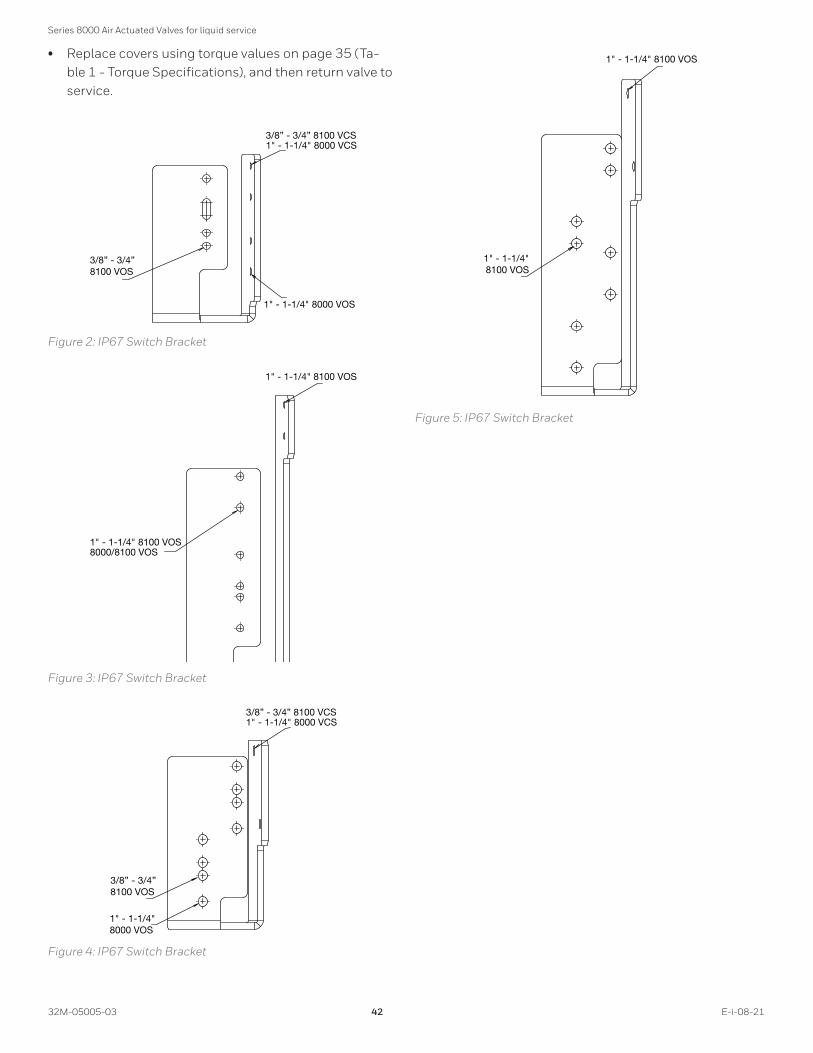
• Replace covers using torque values on page 35 (Ta-ble 1 - Torque Specifications), and then return valve to service.
3/8” - 3/4” 8100 VOS
1" - 1-1/4" 8000 VOS
3/8” - 3/4” 8100 VCS1" - 1-1/4" 8000 VCS
Figure 2: IP67 Switch Bracket
1" - 1-1/4" 8100 VOS8000/8100 VOS
1" - 1-1/4" 8100 VOS
Figure 3: IP67 Switch Bracket
3/8” - 3/4” 8100 VOS
3/8” - 3/4” 8100 VCS1" - 1-1/4" 8000 VCS
1" - 1-1/4"8000 VOS
Figure 4: IP67 Switch Bracket
1" - 1-1/4"8100 VOS
1" - 1-1/4" 8100 VOS
Figure 5: IP67 Switch Bracket

Series 8000 Air Actuated Valves for liquid service
E-i-08-21 43 32M-05005-03
Operating InstructionsRefer to appropriate catalog bulletin and specification page for operating sequence applying to your specific valve. Never operate valve until all essential allied equip-ment is operative and any necessary purges completed. Failure of valve to operate normally indicates that it is not powered or supply air pressure is not adequate. Check this first!
Main system shut-off should always be accomplished with an upstream leak-tight manual fuel cock.
Normally-closed shut-off valves begin opening cycle im-mediately upon being powered.
Alternate operator pressuresSeries 8000 Valves may be operated within a range of cyl-inder pressures. Consult charts for application fluid pres-sure and corresponding required actuator pressure.
Maintenance InstructionsMAXON Series 8000 Valves are endurance tested far in excess of the most stringent requirements of the various approval agencies. They are designed for long life even if frequently cycled, and to be as maintenance-free and trouble-free as possible.
A valve operational test should be performed on an an-nual basis. If abnormal opening or closing is observed, the valve should be removed from service and your MAXON representative should be contacted. (See Valve Technical Data page 10-35.1.)
Valve leak test should be performed on an annual basis to assure continued safe and reliable operation. Every MAX-ON valve is operationally tested and meets the require-ments of FCI 70-2 Class VI Seat Leakage when in good operable condition. Zero leakage may not be obtained in the field after it has been in service. For specific recom-mendations on leak test procedures, see MAXON Valve Technical Data page 10-35.2. Any valve that exceeds the allowable leakage, as set forth by your local codes or in-surance requirements, should be removed from service and your MAXON representative should be contacted.
Actuator assembly components require no field lubrica-tion and should never be oiled .
Auxiliary switches, solenoids or complete actuator may be replaced in the field.
Do not attempt field repair of valve body or ac-tuator . Any alterations void all warranties and can create potentially hazardous situations .
If foreign material or corrosive substances are present in the fuel line, it will be necessary to inspect the valve to make certain it is operating properly. If abnormal opening or closing is observed, the valve should be removed from service. Contact your MAXON representative for instruc-tions.
Operator should be aware of and observe characteristic opening/closing action of the valve. Should operation ever become sluggish, remove valve from service and contact MAXON for recommendations.
Specific conditions of use: This equipment includes some external non-metallic parts, including the outer protective coating . The user shall therefore ensure that the equipment is not installed in a location where it may be subjected to external conditions (such as high-pressure steam) which might cause a build-up of electrostatic charges on non-conducting surfaces . Additionally, clean-ing of the equipment should be done only with a damp cloth .
Address inquiries to MAXON. Local worldwide offices may be located at www.maxoncorp.com or by phoning 001-765-284-3304. Include valve serial number and nameplate information.

Series 8000 Air Actuated Valves for liquid service
32M-05005-03 44 E-i-08-21
Solenoid replacement procedure• All power sources both pneumatic and electric must be
de-energized and follow all proper safety procedures prior to servicing valve.
• Use a 4 mm allen wrench to remove the top plate. A 3 mm allen wrench is used to remove the terminal block cover.
• Use a 5/16” open end wrench to hold the cylinder shaft, then use a pair of pliers to unthread the switch indicator from the cylinder shaft. When using pliers, grab the switch indicator from the top.
1
2
3
4
5
6
78
1) Top plate screw M6 x 20, socket head cap screw2) M6 Lock washer3) Top plate4) Switch indicator5) Cylinder shaft6) Terminal block cover7) M5 Lock washer8) Terminal block cover screw M5 x 12, socket head cap screw
• Loosen the liquid tight connector nut where the sole-noid wires come into the top housing. Remove #1 and #2 wire from the ter- minal block.
1
1) Liquid tight connector
• Use a 3/4” wrench to remove the solenoid inlet fitting. An adjustable wrench is used to loosen the housing collar. Slightly loosen the housing collar but do not remove, due to the nut and o-ring located inside the housing becoming dislocated.
1
2
1) Housing collar2) Solenoid inlet fitting
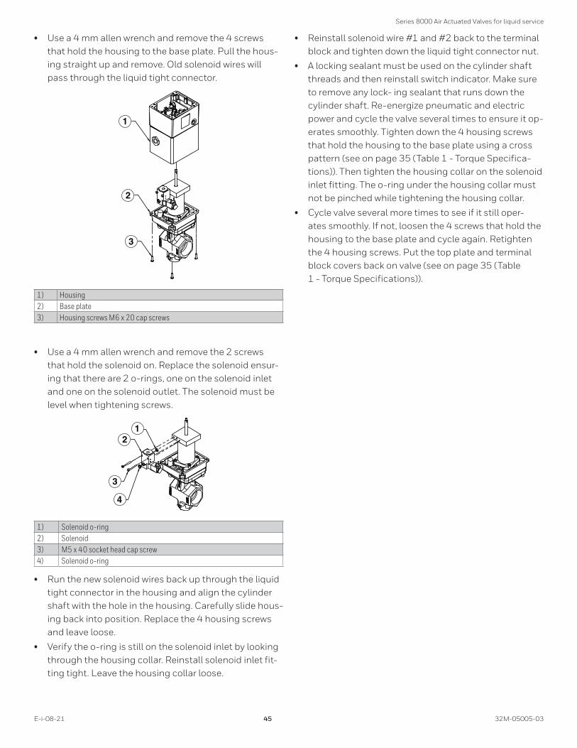
Series 8000 Air Actuated Valves for liquid service
E-i-08-21 45 32M-05005-03
• Use a 4 mm allen wrench and remove the 4 screws that hold the housing to the base plate. Pull the hous-ing straight up and remove. Old solenoid wires will pass through the liquid tight connector.
1
2
3
1) Housing2) Base plate3) Housing screws M6 x 20 cap screws
• Use a 4 mm allen wrench and remove the 2 screws that hold the solenoid on. Replace the solenoid ensur-ing that there are 2 o-rings, one on the solenoid inlet and one on the solenoid outlet. The solenoid must be level when tightening screws.
12
3
4
1) Solenoid o-ring2) Solenoid3) M5 x 40 socket head cap screw4) Solenoid o-ring
• Run the new solenoid wires back up through the liquid tight connector in the housing and align the cylinder shaft with the hole in the housing. Carefully slide hous-ing back into position. Replace the 4 housing screws and leave loose.
• Verify the o-ring is still on the solenoid inlet by looking through the housing collar. Reinstall solenoid inlet fit-ting tight. Leave the housing collar loose.
• Reinstall solenoid wire #1 and #2 back to the terminal block and tighten down the liquid tight connector nut.
• A locking sealant must be used on the cylinder shaft threads and then reinstall switch indicator. Make sure to remove any lock- ing sealant that runs down the cylinder shaft. Re-energize pneumatic and electric power and cycle the valve several times to ensure it op-erates smoothly. Tighten down the 4 housing screws that hold the housing to the base plate using a cross pattern (see on page 35 (Table 1 - Torque Specifica-tions)). Then tighten the housing collar on the solenoid inlet fitting. The o-ring under the housing collar must not be pinched while tightening the housing collar.
• Cycle valve several more times to see if it still oper-ates smoothly. If not, loosen the 4 screws that hold the housing to the base plate and cycle again. Retighten the 4 housing screws. Put the top plate and terminal block covers back on valve (see on page 35 (Table 1 - Torque Specifications)).

For More InformationThe Honeywell Thermal Solutions family of products includes Honeywell Combustion Safety, Eclipse, Exothermics, Hauck, Kromschröder and Maxon. To learn more about our products, visit ThermalSolutions.honeywell.com or contact your Honeywell Sales Engineer.
Honeywell MAXON branded products201 E. 18th StreetMuncie, IN 47302USAwww.maxoncorp.com
Honeywell Process SolutionsHoneywell Thermal Solutions (HTS)1250 West Sam Houston Parkway South Houston, TX 77042
ThermalSolutions.honeywell.com
® U.S. Registered Trademark. © 2021 Honeywell International Inc. 32M-05005-03 e08-21 EAS 50112661-001 Printed in U.S.A.
Related Documents