Maximizing Wind Turbine Energy Capture using Multivariable Extremum Seeking Control Justin Creaby 1 , Yaoyu Li 2,* and John E. Seem 3 1 Vestas Wind Systems, 66 Church St., Leatherhead, KT22 8DP, UK 2 Department of Mechanical Engineering, University of Wisconsin, 3200 N. Cramer St., Milwaukee, WI 53211, USA 3 Controls Group, Johnson Controls, Inc., 507 E. Michigan St., PO Box 423, Milwaukee, WI 53201-0423, USA E-mail: [email protected], [email protected], [email protected] WIND ENGINEERING VOLUME 33, NO. 4, 2009 PP 361–388 361 ABSTRACT Maximizing energy capture has become an important issue as more turbines are installed in low wind areas. This paper investigates the application of extremum seeking control (ESC) to maximizing the energy capture of variable speed wind turbines. The optimal control torque and pitch angle are searched via ESC based on the measurement of the rotor power. The advantage of this method is the independency from accurate turbine modelling and wind measurement. Simulation was conducted on FAST for a wind turbine dynamic model, under smooth, turbulent and field recorded wind profiles. The simulation results demonstrated significant improvement in energy capture compared to the standard control with fixed reference. An anti-windup ESC was applied to overcome the integral windup due to actuator saturation which would otherwise disable the ESC process. Finally, the integrator and high-pass filter resetting schemes were applied to improve the transient under the abrupt changes of wind. NOMENCLATURE C p Power Coefficient d 1 (t) Demodulation Signal d 2 (t) Dither Signal F HP (s) High Pass Filter F I (s) Input Dynamics F LP (s) Low Pass Filter F O (s) Sensor Dynamics K(s) Compensator in ESC k r Torque Gain l(t, u) Measurement of Cost Function M Adaptive Gain n(t) Noise P favg Fractional Average Power Q Hessian matrix of the cost function

Welcome message from author
This document is posted to help you gain knowledge. Please leave a comment to let me know what you think about it! Share it to your friends and learn new things together.
Transcript

Maximizing Wind Turbine Energy Capture usingMultivariable Extremum Seeking Control
Justin Creaby1, Yaoyu Li2,* and John E. Seem3
1Vestas Wind Systems, 66 Church St., Leatherhead, KT22 8DP, UK2Department of Mechanical Engineering, University of Wisconsin, 3200 N. Cramer St., Milwaukee,WI 53211, USA3Controls Group, Johnson Controls, Inc., 507 E. Michigan St., PO Box 423, Milwaukee,WI 53201-0423, USAE-mail: [email protected], [email protected], [email protected]
WIND ENGINEERING VOLUME 33, NO. 4, 2009 PP 361–388 361
ABSTRACTMaximizing energy capture has become an important issue as more turbines are installed in
low wind areas. This paper investigates the application of extremum seeking control (ESC)
to maximizing the energy capture of variable speed wind turbines. The optimal control
torque and pitch angle are searched via ESC based on the measurement of the rotor power.
The advantage of this method is the independency from accurate turbine modelling and
wind measurement. Simulation was conducted on FAST for a wind turbine dynamic model,
under smooth, turbulent and field recorded wind profiles. The simulation results
demonstrated significant improvement in energy capture compared to the standard control
with fixed reference. An anti-windup ESC was applied to overcome the integral windup due
to actuator saturation which would otherwise disable the ESC process. Finally, the
integrator and high-pass filter resetting schemes were applied to improve the transient
under the abrupt changes of wind.
NOMENCLATURECp Power Coefficient
d1(t) Demodulation Signal
d2(t) Dither Signal
FHP(s) High Pass Filter
FI(s) Input Dynamics
FLP(s) Low Pass Filter
FO(s) Sensor Dynamics
K(s) Compensator in ESC
kr Torque Gain
l(t, u) Measurement of Cost Function
M Adaptive Gain
n(t) Noise
Pfavg Fractional Average Power
Q Hessian matrix of the cost function

GREEK SYMBOLSαi Phase Angle between Dither and Demodulating Signals for the i-th input
γ Adaptation Gain
θi Combination of Phase Angle αi and the Phase Response of the i-th Channel of Input
Dynamics
ρ Air Density (kg/m3)
τc Control Torque (Nm)
ωi Dither Frequencies
ωr Rotor Speed (rad/s)
1. INTRODUCTIONRenewable energy has become a major focus for energy and environment sustainability.
Among all the existing renewable energy technologies, wind is considered the most
appropriate energy source for utility level power generation. The US targets 20% wind based
electricity generation, i.e. about 300 GW, by 2030 [1]. The European Technology Platform for
Wind Energy (TPWind) envisions the coverage of electricity generation up to 12–14% by 2020
and 25% of by 2030 [2]. With such scale of wind power penetration, more turbines will be
installed in the medium to low wind areas. In order to reduce the cost-of-energy (COE), it is
critical to increase the efficiency of wind power generation. In addition to improving the
aerodynamic design and site optimization, development of cost-effective control strategies is
an important aspect. Johnson et al. [3] estimated that every percent of energy loss during
turbine operation would cost $100 million per year, based on 100GW of wind based power
generation. Improving the control algorithms on a commercial turbine is a cost-effective
measure of enhancing the wind energy capture. Improved control algorithms can also reduce
hardware and maintenance costs. The objective of this study is to develop a cost-effective control
strategy for maximizing the energy capture when the wind speed is below the rated speed.
The power generation for wind turbines is heavily affected by the aerodynamic
characteristics of wind-turbine interaction. The power coefficient Cp, i.e. the ratio of the
aerodynamic rotor power to the wind power, is mainly affected by the blade pitch angle and
the rotor speed. The rotor speed is often replaced by the tip-speed ratio (TSR), which is
defined as the ratio between the rotational speed of blade tip and the wind speed. The
relationship between the power coefficient and the pitch and TSR is illustrated by a simulation
result as shown in Fig. 1 [4].
On the pitch-speed-Cp surface in Figure 1, there is an optimal pitch and TSR for achieving
the maximum power output. The energy capture can be maximized by controlling the pitch
and rotor speed [4]. With the advancement in power conversion electronics, the rectifier and
converter can convert the variable speed power into the fixed frequency power for grid
integration. The variable-pitch technology has been limited to small turbines, while the
variable-pitch-variable-speed turbines have become the mainstream for utility power
generation.
Previously, most control strategies for maximizing energy capture have relied on some
kind of power map similar to Fig. 1 [5–8], and which have limitations in practice. First, the
results from computational fluid dynamics (CFD) based simulation are questionable in
accuracy. The aerodynamic interactions between wind and the turbine blades are quite
complicated. The wind field around a wind turbine has significant stochastic components due
to turbulence. An experimental study conducted by the US National Renewable Energy
Laboratory (NREL) reported large discrepancies between computational modeling results
and the actual measurement [9]. Second, wind measurement is often inaccurate. The wind
362 MAXIMIZING WIND TURBINE ENERGY CAPTURE USING MULTIVARIABLE EXTREMUM SEEKING CONTROL

field within the turbine rotation sweep has remarkable variations as the turbine size is quite
large for most utility level turbines [10] [11]. Thirdly, model wind turbine characteristics
change with time due to surface wear, dirt, bug or ice buildup, and in consequence, the
aerodynamics and the associated power map will change. Therefore, control strategies that
can adapt to the actual operation are more appropriate for enhancing energy capture.
Adaptive control based on power output has gained attention for maximizing the energy
capture against the inaccurate modeling and unreliable wind measurement. Recently,
adaptive torque control was studied by Johnson et al. [12] [3]. Torque has corresponding
relationship with speed, but it is easier to control than the shaft speed. In their study, the
control torque was chosen to be proportional to the square of the rotor speed. The adaptation
law was developed based on the power signal averaged every 3 hours. According to [3], such
long time period was chosen in part because of the difficulty of obtaining a high correlation
between measurements of wind speed over the entire swept area of the rotor and at
the anemometer which can be located either on the turbine’s nacelle or on a separate
meteorological tower. Another reason for the long adaptation period is that, since the turbine
changes speed at a much slower rate than the wind, the slow responses must be averaged
over time. The test converged to the expected torque gain eventually. However, due to the
use of very long adaptation period (3 hours), the convergence time was about 40 hours. It is
desirable to develop an adaptive control strategy with faster convergence behavior.
Furthermore, the adaptation was based on the fractional power which is defined as the ratio
of the captured power to the available wind power. The latter term was determined by the
cubic law of wind power that relates available wind power to the third power of wind
velocity. Such dependency makes the method sensitive to wind measurement. For field
operation, sensor error and faults in wind measurement could bring forth difficulty.
Therefore, it is also ideal to use adaptive control scheme that is not sensitive to wind
measurement sensor errors.
WIND ENGINEERING VOLUME 33, NO. 4, 2009 363
Figure 1: The relationship between rotor power coefficient, TSR and pitch angle for a typical turbine.
−0.2
−0.4
−0.6
−0.8
−1
−1.20
2 4 6
Tip-speed ratio
Pitch8 10 12
14 15
10
5
0
−5
0
0.2
0.4
Power map
Cp

Another class of control schemes with some adaptation capability is the linear parameter
varying (LPV) control. Recently, Bianchi et al. have developed a gain-scheduling control
strategy for variable-speed turbine operation using a quasi-LPV model [13] [14]. The essence of
this method is to design an H∞ robust controller with the gains adaptive to the parameter
change within a polytope (convex set). For the case of variable-speed wind turbine, the wind
speed and the rotor speed were chosen as the gain-scheduling parameters. Due to such
adaptation, a higher gain can be applied for specific operating point than a constant-gain
controller, thus a better performance could be achieved. The underlying control design
problem was set as a reference tracking problem, i.e. the reference needs to be obtained from
the power map. Therefore this approach may have aforementioned limitation in maximizing
energy capture for actual operation.
More recently, Frost et al. [15] [16] applied the direct model reference adaptive control
(DMRAC) approach to speed regulation problem for Region 3 operation based on collective
pitching. The objective of the adaptive pitch controller was to regulate generator speed and to
reject step disturbances. Model reference adaptive control is a good fit for the speed regulation
problem for Region 3 operation, as the suitable reference is known. However, for Region 2
operation, such reference model is hard to obtain in accurate fashion, and thus self-optimizing
control strategies that can search for unknown and even time-varying optimal reference points
would be more suitable. In this study, we have considered the Extremum Seeking Control.
The ESC [17–19], as a self-optimizing control strategy, has recently drawn attention for wind
turbine control by some researchers [20] [21]. The ESC, as described in the next section, can
search for the unknown and/or time-varying input parameters for optimizing a
performance index. ESC can be considered as a dynamic realization of the gradient search
through the usage of dithering signals. This method has demonstrated its unique benefit
dealing with the systems that are hard to model due to the complex physical and/or chemical
processes involved. ESC has faster searching transient than the static optimization via the
steepest descent, and thus it has been applied to a number of control applications with
nontrivial system dynamics. Komatsu et al. [20] disclosed a brief study of ESC based pitch
control for wind turbine output maximization. A simple case of quadratic map was presented,
and it appeared that the optimal pitch angle under different wind speeds remained the same,
which did not reflect the fact that the optimal pitch varies with wind speed. In addition, this
pitch-only control can be applied only to constant speed wind turbines, which is limited to the
small turbines [21]. Since the variable-speed turbines have dominated the overall wind power
capacity, the impact of ESC would not be as significant if not covering this class. For variable-
speed turbines, simultaneously searching for both the optimal pitch angle and the optimal
rotor speed is necessary for maximizing the energy capture. Furthermore, the simulation
platform in [20] [21] was too simple to reflect the realistic wind input and turbine dynamics.
Under abrupt change of operating condition such as realistic wind, conventional ESC may
experience a long transient and thus some remedy is in need. In addition, as the ESC contains
an integral component by design, the conventional ESC may be disabled by integral windup
due to actuation saturation.
This paper presents a new multi-variable extremum seeking control scheme that
maximizes the energy capture of variable-pitch-variable-speed wind turbines. This improves
the ESC turbine operation in fluctuating wind and with actuator saturation. In addition to the
standard design of ESC, ESC with anti-windup and input resetting were also applied to deal
with the integral windup and to improve the transient performance under abrupt change of
wind speed and direction. The proposed control schemes were validated through simulation
on NREL’s FAST (Fatigue, Aerodynamics, Structures and Turbulence) software [22].
364 MAXIMIZING WIND TURBINE ENERGY CAPTURE USING MULTIVARIABLE EXTREMUM SEEKING CONTROL

WIND ENGINEERING VOLUME 33, NO. 4, 2009 365
The remainder of this paper is organized as follows. Section 2 describes the principle
and design guidelines for multi-variable extremum seeking control, the anti-windup ESC
to overcome the integral windup inherent to the general ESC loop, and two resetting
schemes for improving the transient performance of ESC under abrupt change of
performance map. Section 3 presents the simulation results for single-input and multi-
input ESC based turbine control, the anti-windup ESC and resetting ESC. Section 4
concludes the current work.
2. MULTI VARIABLE EXTREME SEEKING CONTROLThis paper describes a novel multi-variable extremum seeking control scheme for
maximizing the energy capture of variable-speed-variable-pitch wind turbines. The input
parameters are blade pitch angle and generator torque. The objective of the control strategy
is is to maximize the mechanical power output by searching for the optimal pitch angle and
rotor torque for either a constant or time-varying wind speed. The basic idea of ESC will be
described first, followed by the ESC scheme for the wind turbine control.
2.1. Overview of Extremum Seeking ControlExtremum seeking control deals with the on-line optimization problem of finding an
optimizing input uopt (t) for the generally unknown time-varying cost function l (t, u), where
u(t) ∈ Rm is the input parameter vector, i.e.
(1)
Figure 2 shows the block diagram for a typical ESC system [19]. The measurement of the
cost function l(t, u), denoted by y (t), is corrupted by noise n (t). The transfer function FI (s)
denotes the linear dynamics of the mechanism that command the control or optimization
parameter vector u(t). FO (s) denotes the transfer function of the sensor dynamics that
measure the cost function, which is often a low-pass filter for removing noise from
the measurement. The dithering and demodulating signals are denoted by
and , respectively, where
ωi are the dithering frequencies for each input parameter channel, and αi are the phase angles
introduced intentionally between the dithering and demodulating signals. The signal vector
d2(t) contains the perturbation or dither signals used to extract the gradient of the cost
function l (t, u). These signals work in conjunction with the high-pass filter FHP (s), the
demodulating signal and the low-pass filter FLP (s), to produce ad t t tTm1 1( ) [ sin( )...sin( )]= ω ω
d t t tTm1 1( ) [ sin( )...sin( )]= ω ωd t a t a tT
m m m2 1 1 1( ) [ sin( )... sin( )]= + +ω α ω α
u t l t uoptu m
( ) arg min ( , )=∈ℜ
FHP(s)
d1 d2
FLP(s) K(s)
FI (s)l(t, u)
− ∫
Fo(s)y(t) u(t )
n(t )
+
++
+
û
Figure 2: Block diagram of the ESC algorithm.

366 MAXIMIZING WIND TURBINE ENERGY CAPTURE USING MULTIVARIABLE EXTREMUM SEEKING CONTROL
vector-valued signal proportional to the gradient, , of the cost function at the input of
the multivariable integrator, where û is the control input based on the gradient estimation. By
integrating the gradient signal, asymptotic stability of the closed loop system will make the
gradient vanish, i.e., achieving the optimality. Adding compensator K (s) may enhance the
transient performance by compensating the input/output dynamics. Detailed explanation of
ESC can be found in [17–19].
The earliest version of ESC can be dated back to Leblanc’s work in 1922 [23]. There was
great interest in this subject in 1950s and 1960’s [24–26]. The research conducted by Krstic and
his coworkers in the past decade ignited a resurgence of extremum seeking control [17, 18].
Krstic and Wang first provided the stability proof for general SISO nonlinear plants based on
averaging and singular perturbation methods [17]. More design issues were addressed in
another paper by Krstic [18]. Later, the stability proof was extended to discrete-time
situation [27]. The proposed ESC framework has been applied to various applications, such as
maximizing biomass production rate [28], maximizing pressure rise in axial flow compressor [29],
minimizing acoustic pressure oscillation to enhance combustion stability [30], minimizing the
power demand in formation flight [31], and minimizing limit cycling [32], among others. The
extremum seeking control was also studied along different paths. Özgüner and his coworkers
combined ESC with sliding mode control [33–35] to explore the application in the vehicle ABS
control. Based on the assumption of quadratic functional form with a finite number of
parameters, Banavar et al. developed an ESC scheme with an adaptation procedure of on-line
identifying the parameters in the assumed function [36–38].
Multi-parameter tuning is of more practical importance and also presents more
complexity. Rotea [19] and Walsh [39] first studied multi-parameter ESC with constant
parameters. Rotea [19] considered the system setting with corrupting noise for the output
measurement. Simple averaging analysis was conducted in stability proof. The design
problem turned out to be one for the linear time-invariant (LTI) plant after averaging, and a
set of design guidelines was summarized. Later, Ariyur and Krstic [40, 41] presented their
multi-parameter ESC for general time-varying parameters. A systematic design algorithm
based on standard LTI control was developed. Uncertainty of the second order derivative was
included in their design. The scheme is applicable for proper output dynamics and thus faster
perturbation is possible. An analytical procedure was proposed to quantify the level of
design difficulty in terms of the number of parameters and the shape of the unknown
equilibrium. In addition, it was noted that the idea of driving the gradient of a nonlinear map
to zero in extremum seeking was generalized to driving the gradient to any given reference.
A later paper [42] showed the application of this idea to compressor instability control.
In the past several years, more ESC applications have been reported. Li et al. described a
multi-parameter ESC application for maximizing the cooling power of a tunable
thermoacoustic cooler [43]. For a solar power system, the maximum power point tracking was
obtained using the extremum seeking with the panel voltage/current [44]. In [45], the user’s
power output was maximized for an exercise machine by optimizing the velocity set point via
ESC. ESC was also applied to search on-line for parameter settings that minimize fuel
consumption of a dual independent variable cam timing engine running at fixed speed and
torque in a dynamometer test-cell [46]. For a biogas production application described in [47],
the performance of a laboratory-scale up-flow anaerobic fixed-bed reactor was greatly
improved via ESC. For fluid system control, the drag force exerted on a bluff-body was
reduced by using extremum-seeking control [48]. An interesting extension of ESC is in the PID
auto-tuning area [49].
∂∂
l
u( )û
WIND ENGINEERING VOLUME 33, NO. 4, 2009 367
Previous investigations on ESC based wind turbine control for enhancing energy capture
[20, 21], as mentioned in Section I, have been relatively simple and appeared only for small
wind turbines. Its application for the large turbines with variable speed capability, currently
the main stream type, has not been reported. In addition, none of the reported research on
adaptive wind turbine control has dealt with the important issues for the practical operation,
such as the possible windup problem due to the actuator saturation and the slow convergence
rate for rapidly changing wind speed. In this research, a multivariable ESC scheme is proposed
for maximizing the energy capture of wind turbines, including the solutions to the above
practical issues.
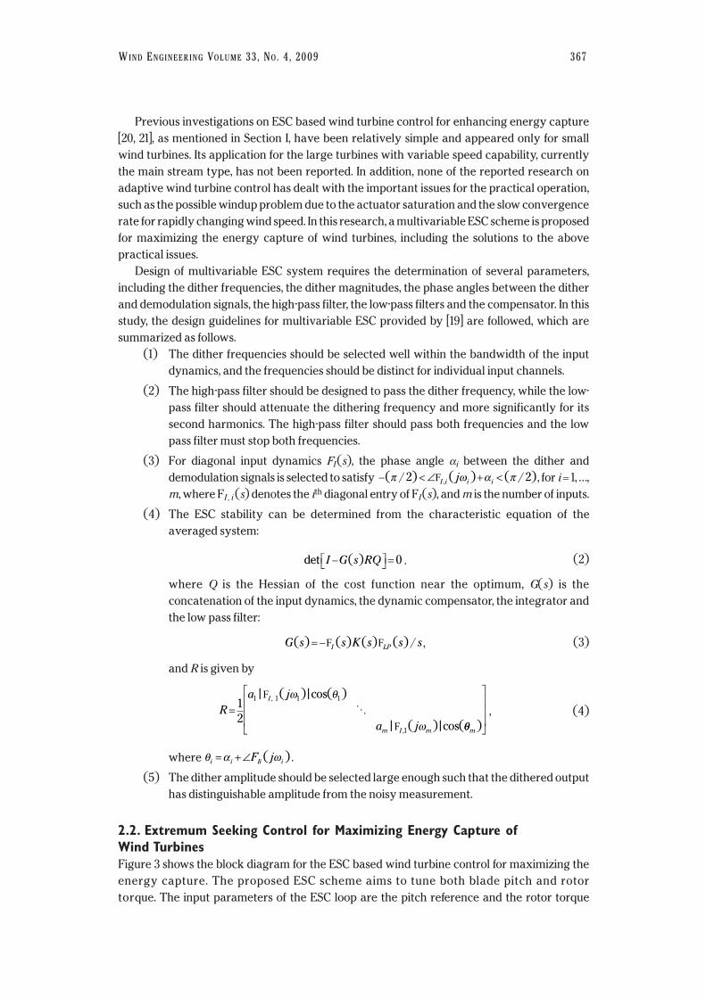
Design of multivariable ESC system requires the determination of several parameters,
including the dither frequencies, the dither magnitudes, the phase angles between the dither
and demodulation signals, the high-pass filter, the low-pass filters and the compensator. In this
study, the design guidelines for multivariable ESC provided by [19] are followed, which are
summarized as follows.
(1) The dither frequencies should be selected well within the bandwidth of the input
dynamics, and the frequencies should be distinct for individual input channels.
(2) The high-pass filter should be designed to pass the dither frequency, while the low-
pass filter should attenuate the dithering frequency and more significantly for its
second harmonics. The high-pass filter should pass both frequencies and the low
pass filter must stop both frequencies.
(3) For diagonal input dynamics FI (s), the phase angle αi between the dither and
demodulation signals is selected to satisfy , for i = 1, …,
m, where FI , i (s) denotes the ith diagonal entry of FI (s), and m is the number of inputs.
(4) The ESC stability can be determined from the characteristic equation of the
averaged system:
. (2)
where Q is the Hessian of the cost function near the optimum, G(s) is the
concatenation of the input dynamics, the dynamic compensator, the integrator and
the low pass filter:
, (3)
and R is given by
, (4)
where .
(5) The dither amplitude should be selected large enough such that the dithered output
has distinguishable amplitude from the noisy measurement.
2.2. Extremum Seeking Control for Maximizing Energy Capture of Wind TurbinesFigure 3 shows the block diagram for the ESC based wind turbine control for maximizing the
energy capture. The proposed ESC scheme aims to tune both blade pitch and rotor
torque. The input parameters of the ESC loop are the pitch reference and the rotor torque
θ α ωi i Ii iF j= + ∠ ( )
R
a j
a j
I
m I m
= 1
2
1 1 1 1
1
| ( ) | cos( )
| ( ) | cos(
,
,
F
F
ω θ
ωO
θθm )
G s s K s s sI LP( ) ( ) ( ) ( ) /= −F F
det ( )I G s RQ− = 0
− < ∠ + <( / ) ( ) ( / ),π ω α π2 2FI i i ij

368 MAXIMIZING WIND TURBINE ENERGY CAPTURE USING MULTIVARIABLE EXTREMUM SEEKING CONTROL
reference. The output variable is the rotor power. Notice that the signal flow after the high pass
filter FHP (s) is a two-dimensional vector, highlighted with bold lines. For the actual turbine, the
pitch angle can be measured by the encoder installed at the pitching shaft, and the inner loop
controller GCP (s) is used for pitch servo. The rotor torque can be determined from current, and
regulated by the inner loop controller GCS (s). The idea of torque control in [3] proved to be
effective in speeding up the tuning performance and thus adopted in this study. The control
torque is selected to be proportional to the square of the rotor speed, i.e. τ =kτωr2, where is ωr is
the rotor speed. The torque gain kτ is the tuning input, instead of the torque directly.
Although ESC does not require knowledge of the optimal reference input, knowledge of
the input dynamics and shape profile (second-order derivative) information is important for
successful design. Also, as ESC can deal with local optimum only, validation of the existence of
global optimum within the operating region is important. All this information needs to be
investigated via quality dynamic modeling of the turbine system. In this study, the wind
turbine dynamics is modeled by the NREL’s FAST software [20]. FAST provides a
streamlined prediction of wind-turbine loads and responses, and is suitable for modeling
both two- and three-bladed, horizontal-axis wind turbines.
2.3. Integral Windup and Anti-windup ESCSaturation occurs in any control system because the dynamic range of all real actuators is
limited. The averaging analysis of ESC in [17] showed that, at a larger time scale, the ESC can
be deemed as a linear system regulating the gradient signal with a proportional-integral
(PI) controller. When saturation occurs in the ESC loop, integrator wind-up is inevitable, and
in consequence, leads to the windup phenomena. For wind turbine operation, both pitch
angle and rotor speed can be limited, due to the design and operational constraints. There
are always times that pitch angle and/or rotor speed have to be saturated for quite some
time, and thus integral windup would occur if ESC were applied. The ESC could thus be
disabled after the rotor speed or pitch angle saturation is removed. An anti-windup ESC
using the back-calculation method [48] is proposed as shown in Figure 4.
+
+
+
++
+
−
+
+
n
uT
uP
d1T d2T
FLPT(s) −
−
FHP (s)
FLPP (s)
�� (� )
�� (� )
��� (� )
��� (� )
d1Pd 2P
Pitch
RotorPower
���
�����
PitchReference
TorqueReference
RotorTorque
∫
∫
Figure 3: Block diagram of ESC based wind turbine control for maximizing energy capture.

WIND ENGINEERING VOLUME 33, NO. 4, 2009 369
2.4. Resetting ESC for Transient Performance ImprovementSudden change of wind speed and direction often occurs in a gusty wind field. When an abrupt
change occurs, it can cause the corresponding change for the performance (power) map, and
thus the optimum shifts away from the previous optimum. Under such circumstances, ESC may
take a long time to converge to the new optimum. In order to improve the transient
performance, two resetting schemes were proposed. Figure 5 shows the first scheme, the
integrator resetting. Large magnitude change of gradient caused by sudden changes in wind
speed is detected and the output of the integrator is then reset to zero for some time duration. The
y
n
u
− µ∫
FHP(s)
Fo(s) l (t, u) FI(s)
FLP(s)
d1(t ) d2(t )
++
++
GradientDetector
0
n
y u
++
++
++
+
−
Actuator Saturation
FLPT (s)
I(t, u)
Gain
FI (s)
− µ∫FHP (s)
d1(t ) d 2(t )
FO (s)
Figure 5: Block diagram of ESC with integrator resetting.
d1(t ) d2(t )
+
+
+
+n
y u
ResettingLogic
Step-ChangeDetector
FHP (s) FLP(s )
Fo (s) l (t, u ) FI(s)
− µ∫
Figure 6: Block diagram of ESC with high-pass filter resetting.
Figure 4: Block diagram of anti-windup ESC.
370 MAXIMIZING WIND TURBINE ENERGY CAPTURE USING MULTIVARIABLE EXTREMUM SEEKING CONTROL
other scheme is to reset the input to the high-pass filter in the ESC loop, as shown in Figure 6. This
scheme also detects a step change in the output signal and resets the input to the high pass filter
to some predefined value.
3. SIMULATION STUDYIn order to validate the proposed ESC based wind turbine control for maximizing energy
capture, simulation has been conducted on the NREL’s FAST software [20] and Matlab®
Simulink. FAST is a medium complexity horizontal axis wind turbine design code which can
calculate aerodynamic and mechanical properties. FAST has the ability to interface with
Simulink which allows easy development of turbine controls. Aerodyn [49], also developed by
NREL, is used to simulate aerodynamic forces on the turbine blades. TurbSim [50], also
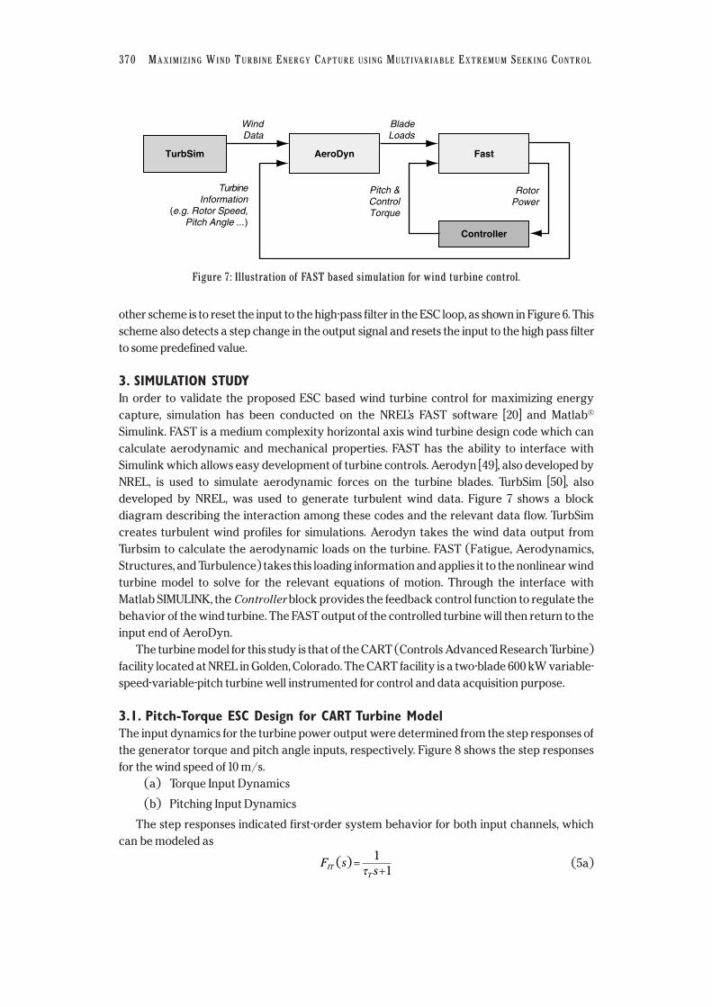
developed by NREL, was used to generate turbulent wind data. Figure 7 shows a block
diagram describing the interaction among these codes and the relevant data flow. TurbSim
creates turbulent wind profiles for simulations. Aerodyn takes the wind data output from
Turbsim to calculate the aerodynamic loads on the turbine. FAST (Fatigue, Aerodynamics,
Structures, and Turbulence) takes this loading information and applies it to the nonlinear wind
turbine model to solve for the relevant equations of motion. Through the interface with
Matlab SIMULINK, the Controller block provides the feedback control function to regulate the
behavior of the wind turbine. The FAST output of the controlled turbine will then return to the
input end of AeroDyn.
The turbine model for this study is that of the CART (Controls Advanced Research Turbine)
facility located at NREL in Golden, Colorado. The CART facility is a two-blade 600 kW variable-
speed-variable-pitch turbine well instrumented for control and data acquisition purpose.
3.1. Pitch-Torque ESC Design for CART Turbine ModelThe input dynamics for the turbine power output were determined from the step responses of
the generator torque and pitch angle inputs, respectively. Figure 8 shows the step responses
for the wind speed of 10 m/s.
(a) Torque Input Dynamics
(b) Pitching Input Dynamics
The step responses indicated first-order system behavior for both input channels, which
can be modeled as
(5a)F ssIT
T
( ) =+
1
1τ
TurbineInformation
(e.g. Rotor Speed,Pitch Angle ...)
TurbSim AeroDyn Fast
Controller
WindData
BladeLoads
Pitch &ControlTorque
RotorPower
Figure 7: Illustration of FAST based simulation for wind turbine control.

WIND ENGINEERING VOLUME 33, NO. 4, 2009 371
. (5b)
For control torque dynamics, the blade pitch was fixed at −1°, and the value of kτ was
stepped up and down a number of times of different step sizes. The time constant τk was
calculated for each step change, which ranged from 6.3 to 7.7 seconds. Similarly, the time
constant for the pitching input dynamics was determined ranging from 5.2 to 5.7 seconds. As
an average of measurement, τT and τP were set to be 5.5 seconds and 6.63 seconds,
respectively.
F ssIP
P
( ) =+
1
1τ
180160140120100
50
Torq
ue g
ain
100 150 200 250 300 350 400 450 500 550
400350
300
250
20050 100 150 200 250 300
Time (sec)
(a) Torque input dynamics
350 400 450 500 550
40
35
3050
Rot
or s
peed
Rot
or p
ower
100 150 200 250 300 350 400 450 500 550
Simulated dataFitted data
Time (sec)
(b) Pitching input dynamics
43210
−1−2−3
50 100 150 200 250 300 350 400 450 500 550
Pitc
h
290280
270
260
250
240
23050 100 150 200 250 300 350 400 450 500 550
Rot
or p
ower
Simulated dataFitted data
Figure 8: Rotor power with various step changes to the pitch angle and torque gain.

372 MAXIMIZING WIND TURBINE ENERGY CAPTURE USING MULTIVARIABLE EXTREMUM SEEKING CONTROL
The fundamental period of the dither signals was set at 10 times the time constant of its
input dynamics: and . The following high-pass filter FHP (s) was selected to pass frequencies
higher than the lowest dithering frequency, i.e. ωk :
(6)
The following low pass filter FLP (s) was chosen to attenuate the dither frequencies:
(7)
The low pass filter has magnitude attenuation of 10.7 dB at ωT and 23 dB at 2ωk. Figure 9 shows
the Bode plot of the input dynamics, high-pass and low-pass filter, with the dithering frequencies
labeled. The dithering amplitude for the multivariable pitch ranges 0.2° to 2° as the turbulence
intensity varies from 0% to 20%. The dithering amplitude for the multivariable torque gain ranges
2 to 20 as the turbulence intensity varies from 0% to 20%. The phase angles were chosen as:
, leading to , and .
3.2. Simulation Results of Single Input ESCThis sub-section presents the simulation results for single-input ESC, i.e. when only pitch or
torque control is applied. The single-input ESC is applicable for simpler turbine operations
such as fixed-speed or variable-speed with almost fixed optimum pitch angle. The design
process is similar to, although simpler than, the two-input ESC design presented in Section 3.1.
The details of the design process are omitted due to length limit.
Following the design procedure similar to Section 3.1, the dither frequency was selected as
. The high pass filter FHPP (s) was chosen to be
, (8)F ss
s sHPP ( )
. . .=
+ × × +
2
2 22 0 58 0 064 0 064
ωP rad s= 0 0806. /
θ α ωP P IP PF j= +∠ ≈ −( ) .0 05°θ α ωT T IT TF j= +∠ ≈( ) .0 05°α α πT P rad= = 0 178. ( )
F ss s
LP ( ).
. . .=
+ × × +0 05
2 0 6 0 05 0 05
2
2 2
Fs
s sHP =
+ × × +
2
2 22 0 58 0 045 0 045. . .
Figure 9: Input dynamics, high-pass and low-pass filter for pitch-torque ESC.
0
−20
−40
−60
−80
20
Frequency (rad/sec)
Pha
se (
deg)
Mag
nitu
de (
dB)
Pitch dither frequency Torque dither frequency
1359045
0−45−90
−135−180
10−3 10−2 10−1 100 101
180
Input dynamicsHigh pass filterLow pass filter

WIND ENGINEERING VOLUME 33, NO. 4, 2009 373
5000
11
10.5
10
Win
d sp
eed
(m/s
)
9.5
91000 1500 2000 2500 3000 3500
5000
2
1
Pitc
h (d
eg)
0
−1
1000 1500 2000 2500 3000 3500
5000
300
220
280
Rot
or p
ower
(kW
)
260
240
1000 1500Time (sec)
2000 2500 3000 3500
Turbine with standard controlTurbine with ESC control
Figure 10: Pitch ESC under a smooth 10 m/s wind.
with nearly unit gain at ωP . The low pass filter FLPP (s) was designed as
. (9)
with magnitude attenuation in excess of 8 dB at ωP and 20 dB at 2ωP . To improve tracking, the
phase angle between the dither and demodulating signal is chosen to be: ,
which results in .
The pitch ESC was first simulated for a constant wind of 10 m/s without turbulence. The
dithering amplitude aP was selected to be 0.2° for steady wind. The static map obtained from
FAST simulation showed that the optimum pitch angle occurs at −1.1°. To test the proposed
controller, the pitch angle was initially set at a non-optimal value of +2°. As shown in Figure 10,
the pitch angle converges to the optimum −1.1° and the power is thus maximized. The setting
time was about 420 seconds and the steady state errors for pitch and power were 0.1° and 0.5
kW, respectively. For the simulated period, the energy capture improvement was 5.7%.
The simulation was then repeated with turbulent wind of 2% turbulence intensity, with the
initial pitch angle set at +2° again. The dithering amplitude had to be increased to 0.5° for such
turbulence intensity. Figure 11 shows the result. The pitch converges on the optimum and the
power is maximized. Convergence occurs within 1500 seconds. The pitch angle converges to
within 0.15°. The power capture improvement is 4.7%.
For the torque ESC controller, the dithering frequency was chosen to be .
The high pass filter, FHPT (s) was designed as
, (10)
with nearly unit gain at ωT . The low pass filter is designed to attenuate the dither frequency.
The following low pass filter was chosen:
, (11)F ss s
LPT ( ).
* . * . * .=
+ +0 055
2 0 6 0 055 0 055
2
2 2
F ss
s sHPT ( )
. . .=
+ × × × +
2
2 22 0 58 0 071 0 071
ωT rad s= 0 0887. /
θ α ωP P IP PF j= +∠ ≈( ) 0°α πP rad= 0 179. ( )
F ss s
LPP ( ).
. . .=
+ × × +0 055
2 0 6 0 055 0 055
2
2 2

with magnitude attenuation in excess of 8 dB at ωk and 20 dB at 2ωk . The phase angle between
dithering and demodulating signals was chosen as , resulting in
. The dithering amplitude was selected as 5 for steady winds, but has to
increase up to 20 as turbulence intensity reaches 20%.
The nominal value of kτ can be calculated from the following equation from [3],
. (14)
For the CART turbine, with ρ = 1 kg/m3, R = 21.65m, Cpmax = 0.4, λ* = 7.5 and the gearbox ratio
of 43.2, we obtained kτ to be 164 m5/rad3. This value was used as the initial value of kτ for the
τ ρλ
ω ωτc
pAR
Ck= =1
23
3
2 2max
*
θ α ωk k Ik kF j= +∠ ≈( ) 0°α πk rad= 0 179. ( )
374 MAXIMIZING WIND TURBINE ENERGY CAPTURE USING MULTIVARIABLE EXTREMUM SEEKING CONTROL
5000
10.5
10
Win
d sp
eed
(m/s
)
9.5
1000 1500 2000 2500 3000 3500
5000
2
1
Pitc
h (d
eg)
0
−1
1000 1500 2000 2500 3000 3500
5000
280
300
Rot
or p
ower
(kW
)
260
240
1000 1500Time (sec)
Turbine with ESC control
Turbine with standard control
2000 2500 3000 3500
Figure 11: Pitch ESC under 10 m/s wind with 2% turbulence.
5000
10.5
11
10
Win
d sp
eed
(m/s
)
9.5
91000 1500 2000 2500 3000 3500
5000
160
140
Torq
ue g
ain
k
120
1001000 1500 2000 2500 3000 3500
5000
280
300
Rot
or p
ower
(kW
)
260
2401000 1500
Time (sec)
Turbine with ESC control Turbine with standard control
2000 2500 3000 3500
Figure 12: Torque ESC with a smooth 10 m/s wind.
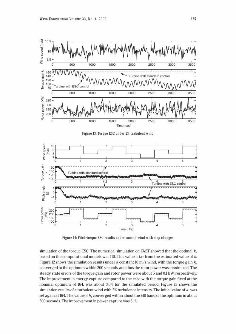
simulation of the torque ESC. The numerical simulation on FAST showed that the optimal kτ
based on the computational models was 110. This value is far from the estimated value of k.
Figure 12 shows the simulation results under a constant 10 m/s wind, with the torque gain kτ
converged to the optimum within 200 seconds, and thus the rotor power was maximized. The
steady state errors of the torque gain and rotor power were about 5 and 0.1 kW, respectively.
The improvement in energy capture compared to the case with the torque gain fixed at the
nominal optimum of 164, was about 3.6% for the simulated period. Figure 13 shows the
simulation results of a turbulent wind with 2% turbulence intensity. The initial value of kτ was
set again at 164. The value of kτ converged within about the ±10 band of the optimum in about
500 seconds. The improvement in power capture was 3.1%.
WIND ENGINEERING VOLUME 33, NO. 4, 2009 375
5000
10.5
10
Win
d sp
eed
(m/s
)
9.5
1000 1500 2000 2500 3000 3500
5000
160140
Torq
ue g
ain
k
120100
80
1000 1500 2000 2500 3000 3500
5000
300
320
Rot
or p
ower
(kW
)
280
260
1000 1500Time (sec)
Turbine with ESC control
Turbine with standard control
2000 2500 3000 3500
Figure 13: Torque ESC under 2% turbulent wind.
10Win
d sp
eed
(m/s
)
72 3 4 5
89
10
10
Torq
ue g
ain
k
1002 3 4 5
120140160
10
Pitc
h an
gle
(¡)
2 3 4 5
−1
01
10
Rot
or p
ower
(kW
)
2 3Time (Hrs)
4 5
150100
200250
Turbine with standard control
Turbine with ESC control
Figure 14: Pitch-torque ESC results under smooth wind with step changes.
3.3. Simulation Results of Pitch-torque ESCThe two-input (pitch-torque) ESC described in Section 3.1 was tested on the CART model. The
initial pitch angle and torque gain were set to +1° and 164, respectively. Figure 14 shows the
simulation results under a staircase smooth wind input of 6 hours long. The wind file used is
smooth with a step change in speed approximately every 30 minutes. The pitch converged to
within 0.1° of the optimum and the value of k converged to between 100 and 120. The obtained
power is within 99% of the maximum. In this case the energy captured was increased by 8.8%.
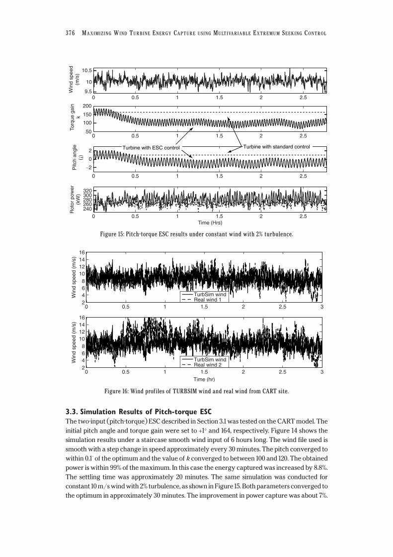
The settling time was approximately 20 minutes. The same simulation was conducted for
constant 10 m/s wind with 2% turbulence, as shown in Figure 15. Both parameters converged to
the optimum in approximately 30 minutes. The improvement in power capture was about 7%.
376 MAXIMIZING WIND TURBINE ENERGY CAPTURE USING MULTIVARIABLE EXTREMUM SEEKING CONTROL
0.50
Win
d sp
eed
(m/s
)
9.51 1.5 2 2.5
10
10.5
0.50
Torq
ue g
ain
k
501 1.5 2 2.5
100
150
200
0.50
Pitc
h an
gle
(¡)
1 1.5 2 2.5
−2
0
2
0.50
Rot
or p
ower
(kW
)
1 1.5Time (Hrs)
2 2.5
280260240
300320
Turbine with ESC control Turbine with standard control
Figure 15: Pitch-torque ESC results under constant wind with 2% turbulence.
16
Win
d sp
eed
(m/s
) 141210
8642
0 0.5 1 1.5Time (hr)
2 2.5 3
16
Win
d sp
eed
(m/s
) 141210
8642
0 0.5 1 1.5 2 2.5 3
TurbSim wind Real wind 1
TurbSim wind Real wind 2
Figure 16: Wind profiles of TURBSIM wind and real wind from CART site.
Increasing the dither amplitude was critical for improving the transient performance with
turbulent wind.
Further simulation was performed using two sets of 3-hour actual wind data recorded at
the CART facility site. Figure 16 shows both sets of real wind data compared to wind data from
TurbSim with 16% turbulence. A wind with 16% turbulence was chosen because it is very
WIND ENGINEERING VOLUME 33, NO. 4, 2009 377
2
64
8101214
0 0.5 1 1.5 2 2.5 3
0 0.5 1 1.5 2 2.5 3
0 0.5 1 1.5 2 2.5 3
0 0.5 1 1.5 2 2.5 3
Turbine with ESC control Turbine with standard control
Win
d sp
eed
(m/s
)
50
100
150
200
Torq
ue g
ain
(k)
−5
0
5
Pitc
h an
gle
(°)
200
400
600
Rot
or p
ower
(kW
)
Figure 17: Pitch-torque ESC results under real wind data #1 from CART site.
15
10
200150100
50
5
0 0.5 1 1.5 2 2.5 3
0 0.5Turbine with standard control Turbine with ESC control
Rot
or p
ower
(kW
)P
itch
angl
e(¡
)To
rque
gai
n(k
)W
ind
spee
d(m
/s)
1 1.5 2 2.5 3
5
0
−50 0.5 1 1.5 2 2.5 3
1000
600800
200400
0 0.5 1 1.5
Time (Hrs)
2 2.5 3
Figure 18: Pitch-torque ESC results under real wind data #2 from CART site.

similar in wind speed variation to that of the real wind. It appears that both wind files have
similar characteristics to that of the wind file created by TurbSim.
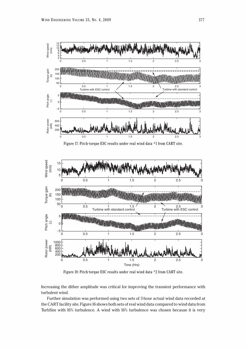
The pitch-torque ESC was simulated using the above actual wind data, respectively. For
the first wind data (Fig. 17), the initial pitch and torque gain were set at +5° and 180 kg.m3/rad3,
respectively. Such values were selected to clearly show convergence towards the optimum.
The convergence was achieved with longer transient, about 1.3 hours due to the increased
turbulence. For the 3 hour operation, the total increase in energy capture was 26%. The same
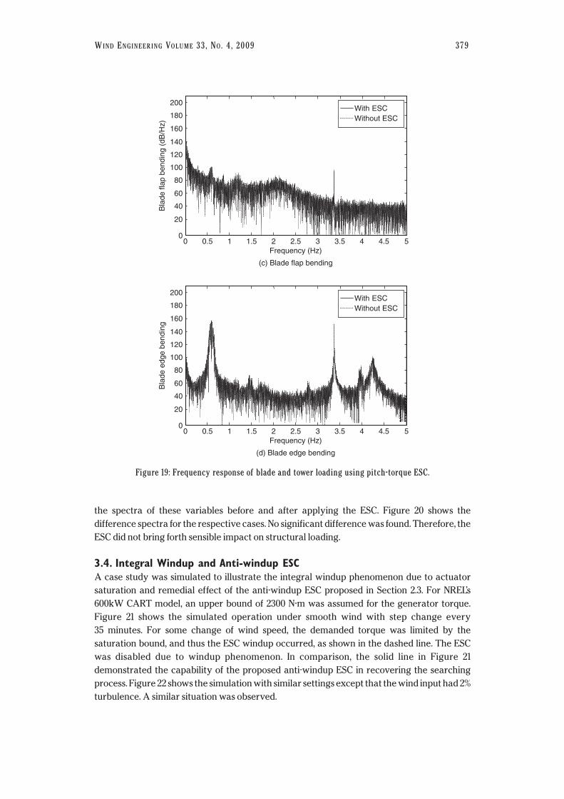
ESC setting was repeated for the second wind data as in Fig. 18. The energy capture improved
by 28%, with about 1.2 hours of convergence time. Compared to the previous cases, the
significant larger improvement in energy capture was mainly due to larger deviation of the
initial setting from the optimum. Nevertheless, the convergence time seemed quite improved
than that reported in [3].
As fatigue loading is critical for the reliability of wind turbines, it is important to inspect the
effect of any control strategy on the structural loading for the turbine. The effect of ESC on
structural loading was briefly investigated. For the pitch-torque simulation with approximately
15% turbulence as in Figure 18, four variables of interest were recorded: tower fore-aft, tower
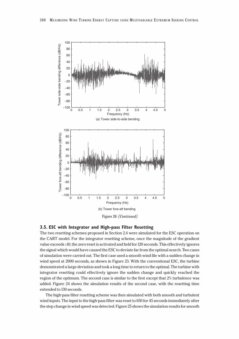
side-to-side, blade flap and blade edge bending moment. Figure 19 shows the comparison of
378 MAXIMIZING WIND TURBINE ENERGY CAPTURE USING MULTIVARIABLE EXTREMUM SEEKING CONTROL
200
180
160
140
120
100
80
60
40
20
00 0.5 1 1.5 2 2.5
Frequency (Hz)
(a) Tower side-to-side bending
3 3.5 4 4.5
Tow
er s
ide-
side
ben
ding
(dB
/Hz)
5
With ESCWithout ESC
200
180
160
140
120
100
80
60
40
20
00 0.5 1 1.5 2 2.5
Frequency (Hz)
(b) Tower fore-aft bending
3 3.5 4 4.5
Tow
er fo
re-a
ft be
ndin
g (d
B/H
z)
5
With ESCWithout ESC
Figure 19: (Continued)
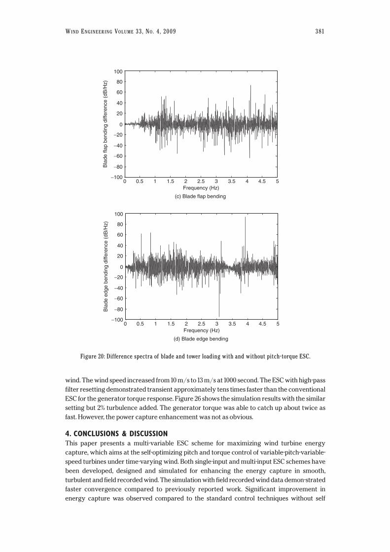
the spectra of these variables before and after applying the ESC. Figure 20 shows the
difference spectra for the respective cases. No significant difference was found. Therefore, the
ESC did not bring forth sensible impact on structural loading.
3.4. Integral Windup and Anti-windup ESCA case study was simulated to illustrate the integral windup phenomenon due to actuator
saturation and remedial effect of the anti-windup ESC proposed in Section 2.3. For NREL’s
600kW CART model, an upper bound of 2300 N-m was assumed for the generator torque.
Figure 21 shows the simulated operation under smooth wind with step change every
35 minutes. For some change of wind speed, the demanded torque was limited by the
saturation bound, and thus the ESC windup occurred, as shown in the dashed line. The ESC
was disabled due to windup phenomenon. In comparison, the solid line in Figure 21
demonstrated the capability of the proposed anti-windup ESC in recovering the searching
process. Figure 22 shows the simulation with similar settings except that the wind input had 2%
turbulence. A similar situation was observed.
WIND ENGINEERING VOLUME 33, NO. 4, 2009 379
200
180
160
140
120
100
80
60
40
20
00 0.5 1 1.5 2 2.5
Frequency (Hz)
(c) Blade flap bending
3 3.5 4 4.5
Bla
de fl
ap b
endi
ng (
dB/H
z)
5
With ESCWithout ESC
200
180
160
140
120
100
80
60
40
20
00 0.5 1 1.5 2 2.5
Frequency (Hz)
(d) Blade edge bending
3 3.5 4 4.5
Bla
de e
dge
bend
ing
5
With ESCWithout ESC
Figure 19: Frequency response of blade and tower loading using pitch-torque ESC.
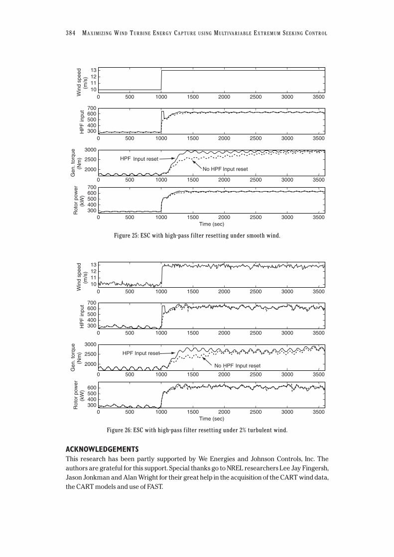
3.5. ESC with Integrator and High-pass Filter ResettingThe two resetting schemes proposed in Section 2.4 were simulated for the ESC operation on
the CART model. For the integrator resetting scheme, once the magnitude of the gradient
value exceeds ±10, the zero-reset is activated and held for 120 seconds. This effectively ignores
the signal which would have caused the ESC to deviate far from the optimal search. Two cases
of simulation were carried out. The first case used a smooth wind file with a sudden change in
wind speed at 2000 seconds, as shown in Figure 23. With the conventional ESC, the turbine
demonstrated a large deviation and took a long time to return to the optimal. The turbine with
integrator resetting could effectively ignore the sudden change and quickly reached the
region of the optimum. The second case is similar to the first except that 2% turbulence was
added. Figure 24 shows the simulation results of the second case, with the resetting time
extended to 130 seconds.
The high-pass filter resetting scheme was then simulated with both smooth and turbulent
wind inputs. The input to the high-pass filter was reset to 650 for 45 seconds immediately after
the step change in wind speed was detected. Figure 25 shows the simulation results for smooth
380 MAXIMIZING WIND TURBINE ENERGY CAPTURE USING MULTIVARIABLE EXTREMUM SEEKING CONTROL
100
80
60
40
20
Tow
er s
ide-
side
ben
ding
diff
eren
ce (
dB/H
z)
0
−20
−40
−60
−80
−1000 0.5 1 1.5 2 2.5
Frequency (Hz)3 3.5 4 4.5 5
(a) Tower side-to-side bending
100
80
60
40
20
Tow
er fo
re-a
ft be
ndin
g di
ffere
nce
(dB
/Hz)
0
−20
−40
−60
−80
−1000 0.5 1 1.5 2 2.5
Frequency (Hz)
3 3.5 4 4.5 5
(b) Tower fore-aft bending
Figure 20: (Continued)
wind. The wind speed increased from 10 m/s to 13 m/s at 1000 second. The ESC with high-pass
filter resetting demonstrated transient approximately tens times faster than the conventional
ESC for the generator torque response. Figure 26 shows the simulation results with the similar
setting but 2% turbulence added. The generator torque was able to catch up about twice as
fast. However, the power capture enhancement was not as obvious.
4. CONCLUSIONS & DISCUSSIONThis paper presents a multi-variable ESC scheme for maximizing wind turbine energy
capture, which aims at the self-optimizing pitch and torque control of variable-pitch-variable-
speed turbines under time-varying wind. Both single-input and multi-input ESC schemes have
been developed, designed and simulated for enhancing the energy capture in smooth,
turbulent and field recorded wind. The simulation with field recorded wind data demon-strated
faster convergence compared to previously reported work. Significant improvement in
energy capture was observed compared to the standard control techniques without self
WIND ENGINEERING VOLUME 33, NO. 4, 2009 381
100
80
60
40
20
Bla
de fl
ap b
endi
ng d
iffer
ence
(dB
/Hz)
0
−20
−40
−60
−80
−1000 0.5 1 1.5 2 2.5
Frequency (Hz)3 3.5 4 4.5 5
(c) Blade flap bending
100
80
60
40
20
Bla
de e
dge
bend
ing
diffe
renc
e (d
B/H
z)
0
−20
−40
−60
−80
−1000 0.5 1 1.5 2 2.5
Frequency (Hz)3 3.5 4 4.5 5
(d) Blade edge bending
Figure 20: Difference spectra of blade and tower loading with and without pitch-torque ESC.

382 MAXIMIZING WIND TURBINE ENERGY CAPTURE USING MULTIVARIABLE EXTREMUM SEEKING CONTROL
13
12
11
5
0
22002400
−5
Win
d sp
eed
(m/s
) In
tegr
ator
inpu
t
Gen
.to
rque
(N
m)
Rot
orpo
wer
(kW
)
0 0.5 1 1.5 2 2.5
0 0.5 1 1.5 2 2.5
0 0.5 1 1.5 2 2.5
0 0.5 1 1.5 2 2.5
200018001600
600
500
400
300
Standard ESC Anti-windup ESC
Figure 21: Illustration of windup and anti-windup ESC in control torque under smooth wind.
0 0.5 1 1.5 2 2.5
0 0.5 1 1.5 2 2.5
0 0.5 1 1.5 2 2.5
0 0.5 1 1.5 2 2.5
13
12
11
50
22002400
−5
Win
d sp
eed
(m/s
) In
tegr
ator
inpu
t
Gen
.to
rque
(N
m)
Rot
orpo
wer
(kW
)
2000180016001400
600500400300
Time (Hrs)
Anti-windup ESC Standard ESC
Figure 22: Illustration of windup and anti-windup ESC in control torque under 2% turbulent wind.
optimization of reference. To deal with the integral windup inherent for ESC operation, an
anti-windup ESC scheme was proposed based on the back-calculation method, and then
validated with simulation. In order to improve the transient performance under abrupt
change of wind speed and wind direction, two resetting schemes were proposed: integrator
and high-pass filter resetting. Simulation results showed that both methods can improve the
transient performance, while the integrator resetting seems to work better. The presented
ESC approach has good fit for the objective of maximizing energy capture for Region 2
operation. For Region 3 operation where speed regulation and disturbance rejection are the
primary goals, model reference adaptive control [15] [16] can be a better solution with faster
transient performance. The two adaptive control strategies could be used in combination
for actual operation.

WIND ENGINEERING VOLUME 33, NO. 4, 2009 383
13121110
10050
0−50
100
300200100
600
400
200
500
−50
Win
d sp
eed
(m/s
) G
radi
ent
Inte
grat
orin
put
Tor
que
gain
Rot
or p
ower
(kW
)
3500300025002000Time (sec)
150010005000
3500300025002000150010005000
3500300025002000150010005000
3500300025002000150010005000
3500300025002000150010005000
No integrator reset
Integrator reset
Figure 23: Simulation result for ESC with integrator resetting under smooth wind.
13
Win
d sp
eed
(m/s
) 121110
3500300025002000150010005000
100
Gra
dien
t
500
−503500300025002000150010005000
100
150100
50
600500400300
Inte
grat
orin
put
Tor
que
gain
Rot
or p
ower
(kW
)
500
−503500300025002000150010005000
3500300025002000150010005000
3500300025002000Time (sec)
150010005000
No integrator reset
Integrator reset
Figure 24: Simulation result for ESC with integrator resetting under 2% turbulent wind.
384 MAXIMIZING WIND TURBINE ENERGY CAPTURE USING MULTIVARIABLE EXTREMUM SEEKING CONTROL
0 500 1000 1500 2000 2500 3000 3500
0 500 1000 1500 2000 2500 3000 3500
0 500 1000 1500 2000 2500 3000 3500
0 500 1000 1500 2000Time (sec)
2500 3000 3500
10111213
Win
d sp
eed
(m/s
)
300400500600700
HP
F in
put
2000
2500
3000
Gen
. tor
que
(Nm
)
300400500600700
Rot
or p
ower
(kW
)
No HPF
HPF Input reset
Input reset
Figure 25: ESC with high-pass filter resetting under smooth wind.
0 500 1000 1500 2000 2500 3000 3500
0 500 1000 1500 2000 2500 3000 3500
0 500 1000 1500 2000 2500 3000 3500
0 500 1000 1500 2000Time (sec)
2500 3000 3500
10111213
Win
d sp
eed
(m/s
)
300400500600700
HP
F in
put
2000
2500
3000
Gen
. tor
que
(Nm
)
300400500600
Rot
or p
ower
(kW
)
No
HPF Input reset
HPF Input reset
Figure 26: ESC with high-pass filter resetting under 2% turbulent wind.
ACKNOWLEDGEMENTSThis research has been partly supported by We Energies and Johnson Controls, Inc. The
authors are grateful for this support. Special thanks go to NREL researchers Lee Jay Fingersh,
Jason Jonkman and Alan Wright for their great help in the acquisition of the CART wind data,
the CART models and use of FAST.

REFERENCES1. US Department of Energy. 20% Wind Energy by 2030: Increasing Wind Energy’s
Contribution to U.S. Electricity Supply. DOE/GO-102008-2567. July 2008.
2. European Wind Energy Technology Platform. Strategic Research Agenda: Market
Deployment Strategy from 2008 to 2030. July 2008.
3. Johnson, K.E., Pao, L.Y., Balas, M.J. and Fingersh, L.J. Control of Variable-Speed Wind
Turbines: Standard and Adaptive Techniques for Maximizing Energy Capture. IEEE
Control Systems Magazine, 2006, 2266(3), 70–81.
4. Johnson, K.E., Fingersh, L.J., Balas, M.J. and Pao, L.Y. Methods for Increasing Region 2
Power Capture on a Variable-Speed Wind Turbine. Journal of Solar Energy
Engineering, 2004, 112266(4): 1092–1100.
5. Leithead, W.E. and Conner, B. Control of Variable Speed Wind Turbines: Dynamic
Models. International Journal of Control, 2000, 7733(13), 1173–1188.
6. Leithead, W.E. and Conner, B. Control of Variable Speed Wind Turbines: Design Task.
International Journal of Control, 2000, 7733(10), 1189–1212.
7. Holley, W., Rock, S., and Chaney, K., Control of Variable Speed Wind Turbines below
Rated Wind Speed. Proceedings of ASME/JSME Joint Fluids Engineering Conference,
San Francisco, 1999.
8. Senjyu, T., Sakamoto, R., Urasaki, N., Funabashi, T., Fujita, H. and Sekine, H., Output
Power Leveling of Wind Turbine Generator for All Operating Regions by Pitch Angle
Control. IEEE Transaction on Energy Conversion, 2006, 2211(2), 467–475.
9. Simms, D., Schreck, S., Hand, M. and Fingersh, L.J. NREL Unsteady Aerodynamics
Experiment in the NASA-Ames Wind Tunnel: A Comparison of Predictions to
Measurements. NREL/TP-500-29494, 2001.
10. Hansen, M.O.L., Aerodynamics of Wind Turbines, 2nd edition 2007.
11. Burton, T., Sharpe, D., Jenkins, N. and Bossanyi, E. Wind Energy Handbook, 1st Edition,
2001, Wiley.
12. Johnson, K.E., Adaptive Torque Control of Variable Speed Wind Turbines. Ph.D. Thesis,
University of Colorado at Boulder, 2004.
13. Bianchi, F.D., Mantz, R.J. and Christiansen, C.F. Gain Scheduling Control of Variable-
Speed Wind Energy Conversion Systems Using Quasi-LPV Models. Control Engineering
Practice, 2005, 1133(2), 247–255.
14. Bianchi, F.D., Battista, H.D. and Mantz, R.J. Wind Turbine Control Systems: Principles,
Modeling and Gain Scheduling Design, 2006, Springer.
15. Frost, S.A., Balas, M.J. and Wright, A.D. Direct Adaptive Control of Utility-Scale Wind
Turbines for Enhanced Energy Capture and Aerodynamic Load Mitigation. International
Journal of Robust and Nonlinear Control, Vol. 19, No. 1, pp. 59–71, January 2009.
16. Frost, S.A., Balas, M.J. and Wright, A.D. Adaptive Control of a Utility-Scale Wind Turbine
Operating in Region 3. AIAA 2009-480, Proceedings of ASME Wind Energy
Symposium, Orlando, FL, February 2009.
17. Krstic, M. and Wang, H.-H. Stability of Extremum Seeking Feedback for General
Nonlinear Dynamic Systems. Automatica, 2000, 3366(4), 595–601.
18. Krstic, M. Performance Improvement and Limitations in Extremum Seeking Control.
Systems and Control Letters, 2000, 3399(5), 313–326.
WIND ENGINEERING VOLUME 33, NO. 4, 2009 385

19. Rotea, M.A. Analysis of Multivariable Extremum Seeking Algorithms. Proceedings of
2000 American Control Conference, 2000, Chicago, IL, 433–437.
20. Komatsu, M., Miyamoto, H., Ohmori, H. and Sano, A. Output Maximization Control of
Wind Turbine Based on Extremum Control Strategy. Proceedings of the 2001 American
Control Conference, 1739–1740.
21. Ishii, C., Hashimoto, H. and Ohmori, H. Modeling of Variable Pitch Micro Wind Turbine
and Its Output Optimization Control with Adaptive Extremum Control Scheme.
Transactions of the Japan Society of Mechanical Engineers, Part C, 2003, 6699(11),
3034–3040.
22. Jonkman, J.M. and Buhl, M. FAST User’s Guide. Technical Report NREL/EL-500-38230,
2005.
23. Leblanc, M. Sur l’electrification des Chemins de fer au Moyen de Courants Alternatifs de
Frequence Elevee. Revue Generale de l’Electricite, 1922.
24. Sternby, J. Extremum Control Systems: An Area for Adaptive Control. Preprints of the
Joint American Control Conference. 1980: San Francisco, CA.
25. Åström, K.J. and Wittenmark, B. Adaptive Control, 2nd ed., 1995, Addison-Wesley,
Reading, MA.
26. Tsien, H.S., Engineering Cybernetics, 1954, McGraw-Hill, New York.
27. Choi, J.-Y., Krstic, M., Ariyur, K.B. and Lee, J.S. Extremum Seeking Control for Discrete-
time Systems. IEEE Transactions on Automatic Control, 2002, 4477(2), 318–323.
28. Wang, H.-H., Krstic, M. and Bastin, G. Optimizing Bioreactors by Extremum Seeking.
International Journal of Adaptive Control and Signal Processing, 1999, 1133(8), 651–669.
29. Wang, H.-H., Yeung, S. and Krstic, M. Experimental Application of Extremum Seeking on
an Axial-flow Compressor. IEEE Transactions on Control Systems Technology, 2000,
88(2), 300–309.
30. Banaszuk, A., Zhang, Y. and Jacobson, C.A. Adaptive Control of Combustion Instability
Using Extremum-Seeking. Proceedings of the 2000 American Control Conference,
Chicago, IL, 2000, 416–422.
31. Binetti, P., Ariyur, K.B., Krstic, M. and Bernelli, F. Control of Formation Flight via
Extremum Seeking. Proceedings of the 2002 American Control Conference, 2002,
2848–2853.
32. Wang, H.-H. and Krstic, M. Extremum Seeking for Limit Cycle Minimization. IEEE
Transactions on Automatic Control, 2000, 4455(12), 2432–2437.
33. Drakunov, S., Özgüner, Ü., Dix, P. and Ashrafi, B. ABS Control Using Optimum Search via
Sliding Modes. IEEE Transactions on Control Systems Technology, 1995, 33(1), 79–85.
34. Yu, H. and Özgüner, Ü. Extremum-seeking Control Strategy for ABS System with Time
Delay. Proceedings of the 2002 American Control Conference, 2002, 3753–3758.
35. Yu, H. and Özgüner, Ü. Extremum-seeking Control via Sliding Mode with Periodic
Search Signals. Proceedings of the 41st IEEE Conference on Decision and Control, 2002,
323–328.
36. Speyer, J.L., Banavar, R.N., Chichka, D.F. and Rhee, I. Extremum Seeking Loops with
Assumed Functions. Proceedings of the 39th IEEE Conference on Decision and Control,
2000, 142–147.
37. Banavar, R.N., Chichka, D.F. and Speyer, J.L. Functional Feedback in an Extremum
Seeking Loop, Proceedings of the 40th IEEE Conference on Decision and Control, 2001,
1361–1321.
386 MAXIMIZING WIND TURBINE ENERGY CAPTURE USING MULTIVARIABLE EXTREMUM SEEKING CONTROL

38. Banavar, R.N. Extremum Seeking Loops with Assumed Functions: Estimation and
Control. Proceedings of the 2002 American Control Conference, Anchorage, AK, 2002,
3159–3164.
39. Walsh, G.C., On the Application of Multi-parameter Extremum Seeking Control.
Proceedings of the 2000 American Control Conference, Chicago, IL, 2000, 411–415.
40. Ariyur, K.B. and Krstic, M. Analysis and Design of Multivariable Extremum Seeking.
Proceedings of the 2002 American Control Conference, Anchorage, AK, 2002,
2903–2908.
41. Ariyur, K.B. and Krstic, M. Real-time Optimization by Extremum-Seeking Control, 2003,
Wiley Interscience.
42. Ariyur, K.B. and Krstic, M. Slope Seeking and Application to Compressor Instability
Control. Proceedings of the 41st IEEE Conference on Decision and Control, 2002,
3690–3697.
43. Li, Y., Rotea, M.A., Chiu, G., Mongeau, L.G., Paek, I.-S. Extremum Seeking Control of a
Tunable Thermoacoustic Cooler. IEEE Transactions on Control Systems Technology,
2005, 1133(4), 527–536.
44. Leyva, R., Alonso, C., Queinnec, I., Cid-Pastor, A., Lagrange, D. and Marinez-Salamero, L.
MPPT of Photovoltaic Systems Using Extremum-Seeking Control. IEEE Transactions on
Aerospace and Electronic Systems, 2006, 4422(1), 249–258.
45. Zhang, X.T., Dawson, D.M., Dixon, W.E. and Xian, B., Extremum-seeking Nonlinear
Controllers for a Human Exercise Machine. IEEE/ASME Transactions on Mechatronics,
2006, 1111(2), 233–240.
46. Popovic, D., Jankovic, M., Magner, S. and Teel, A.R. Extremum Seeking Methods for
Optimization of Variable Cam Timing Engine Operation. IEEE Transactions on Control
Systems Technology, 2006, 1144(3), 398–407.
47. Liu, J., Olsson, G. and Mattiasson, B. Extremum-seeking with Variable Gain Control for
Intensifying Biogas Production in Anaerobic Fermentation. Water Science and
Technology, 2006, 5533(4-5), 35–44.
48. Beaudoin, J.F., Cadot, O., Aider, J.L. and Wesfreid, J.E. Bluff-body Drag Reduction by
Extremum-Seeking Control. Journal of Fluids and Structures, 2006, 2222(6–7), 973–978.
49. Killingsworth, N.J. and Krstic, M. PID Tuning Using Extremum Seeking: Online, Model
Free Performance Optimization. IEEE Control Systems Magazine, 2006, 2266(1), 70–79.
50. Åström, K.J. and Rundqwist, L. Integrator Windup and How to Avoid It. Proceedings of
1989 American Control Conference, 1989, 1693–1698.
51. Laino, D. and Hansen, C. AeroDyn User’s Guide, Version 12.50, 2002, NREL.
52. Jonkman, B.J. and Buhl, M.L. TurbSim User’s Guide, Version 1.21, 2007, NREL.
WIND ENGINEERING VOLUME 33, NO. 4, 2009 387

Related Documents