1 CONTENTS 1. Introduction 2 2. Review of Literature 3 3. Anatomy & development of the maxilla & palate. 34 4. Anatomy, Physiology of the Velopharynx 46 and Speech 5. Management of palato-maxillary defects. i) Multidisciplinary approach. 65 ii) Psychological considerations. 75 iii) Materials used in the management. 86 iv) Prosthetic management of soft & hard palate 100 defects in general. v) Prosthetic management of hard palate defects. 107 vi) Prosthetic management of soft palate defects. 178 vii) Prosthetic management of Cleft lip and palate. 200 6. Discussion 226 7. Conclusion 230 8. Bibliography 231

maxillofacial defects.pdf
Oct 25, 2015
library dissertations
Welcome message from author
This document is posted to help you gain knowledge. Please leave a comment to let me know what you think about it! Share it to your friends and learn new things together.
Transcript
1
CONTENTS
1. Introduction 2
2. Review of Literature 3
3. Anatomy & development of the maxilla & palate. 34
4. Anatomy, Physiology of the Velopharynx 46
and Speech
5. Management of palato-maxillary defects.
i) Multidisciplinary approach. 65
ii) Psychological considerations. 75
iii) Materials used in the management. 86
iv) Prosthetic management of soft & hard palate 100
defects in general.
v) Prosthetic management of hard palate defects. 107
vi) Prosthetic management of soft palate defects. 178
vii) Prosthetic management of Cleft lip and palate. 200
6. Discussion 226
7. Conclusion 230
8. Bibliography 231

2
Maxillofacial Prosthetics is the art and science of anatomic,
functional or cosmetic reconstruction by means of non living substitutes of
those regions in the maxilla, mandible, face and even other body parts that
are missing or defective because of surgical intervention, trauma,
pathology or developmental or congenital malformation.
It is considered a sub speciality of Prosthodontics, as many phases
of Maxillofacial Prosthetics are merely logical extensions of
Prosthodontics. The intimate relationship between the two becomes even
more obvious when it is noted that the basic techniques and materials
used are similar if not identical.
Success in Maxillofacial Prosthetics as in Prosthodontics depends
on full cognizance of the principles that underlie facial harmony, colour
matching, anchorage and retention, weight bearing and leverage, durability
and strength of materials used, tissue compatibility and tolerance.
This dissertation attempts to emphasize these principles while
reviewing the rehabilitation of maxillary and palatal defects.

3
The MaxiIlofacial Prosthodontist normally provides appliances and
devices to restore esthetics and function to the patient who cannot be
restored to normal appearance or function by means of plastic
reconstruction. Despite, remarkable advances in surgical management of
oral and facial defects, many such defects especially those involving the
eyes and ears, cannot be satisfactorily repaired by surgery alone. Further,
the increased lifespan of individuals and the growing demand for health
care services puts additional obligations on the maxillofacial
prosthodontist.
Patients with palatal defects labor under handicaps, which cannot
be fully appreciated by those with normal palates. The prosthetic or
non-surgical method of cleft-palate or acquired defects of palate correction
comprises of essentially two forms of appliances i.e. the obturator and the
artificial velum.
The term obturator is taken from the Latin 'obturare' meaning to
stop up. It is an appliance, which corrects any opening of the hard or soft
palate or of both. Early literature states that obturators and prosthesis for
oral deformities were amongst the earliest appliances in the mouth, and
consisted of wads of fabrics, wax, metal, leather and wood.
The following review surveys the literature and attempts to relate this
information to problems encountered in the successful rehabilitation of
patients with maxillofacial defects in the hard and soft palate.

4
Ambrose Pare28 (1510-90) was one of the first of these operators to
furnish description of an obturator. Pare introduced the term 'bec-de-lievre'
(harelip), merely using obturators for closing palatal defects. Obturators
designed by him, had their own means of retention. The first obturator
designed by him, consisted of a small sponge, which would swell by
moisture distilled from the brain and puffed to fill the cavity of the palate so
that the plate could not fall down. A second type of obturator described by
him contained a turnbuckle which could be rotated some 90º by forceps for
retention.
Pierre Fauchard28 (1678-1761) described ingenious obturators that
composed of a stalk, terminating in a screw with wings covered by sponge
to aid in retention.
Fig.1: Mechanical devices that Pare used to close perforation of the palate. (a)- A dry sponge attached to prongs that swell up and provide retention. (b)- A turnbuckle type of arrangement used for retention.
Fig. 2: Fauchard’s designs for palatal obturators. (a) Wings are in the shape of propellers, which can be folded during
insertion and spread out after insertion with special key. (b) Retaining feature is butterfly shaped. (c) An obturator made in 1900 inspired by Fauchard.
5
Stearn 134 (1841) was the first to introduce speech aid prosthesis
Rowell, Hullihen and Sversen84 introduced Velum to obturators. Velum
is an obturator prosthesis designed to close a defect in soft palate.
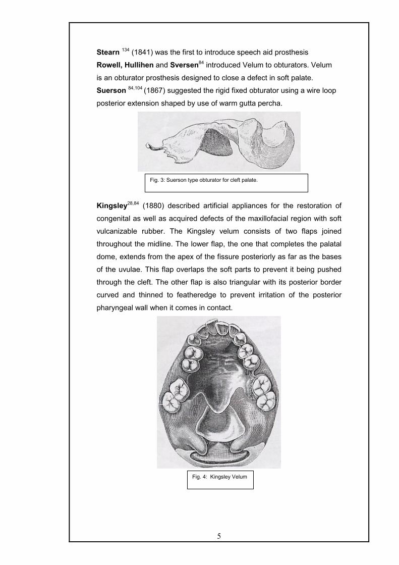
Suerson 84,104 (1867) suggested the rigid fixed obturator using a wire loop
posterior extension shaped by use of warm gutta percha.
Kingsley28,84 (1880) described artificial appliances for the restoration of
congenital as well as acquired defects of the maxillofacial region with soft
vulcanizable rubber. The Kingsley velum consists of two flaps joined
throughout the midline. The lower flap, the one that completes the palatal
dome, extends from the apex of the fissure posteriorly as far as the bases
of the uvulae. This flap overlaps the soft parts to prevent it being pushed
through the cleft. The other flap is also triangular with its posterior border
curved and thinned to featheredge to prevent irritation of the posterior
pharyngeal wall when it comes in contact.
Fig. 3: Suerson type obturator for cleft palate.
Fig. 4: Kingsley Velum

6
Kelsey-Fry5 (1927) stressed the very great need of the close cooperation
between the surgeon and the dental prosthetist and the importance of pre-
operative consultation to decide, as exactly as possible, the amount of
tissue to be removed, which teeth (if any) to preserve and so forth.
Pitchler5 (1929) discussed a vulcanite appliance used after maxillary
resection, which was made in two parts. The upper hollow portion filling the
space created by surgery and fitting lid like into the lower portion or
denture to which it is fastened, when in position by a lateral hook.
Kazanjian5 (1931) described an ingenious arrangement for hinging the
anterior extension of the prosthesis so that the appliance could be more
easily introduced, and after placement the anterior attachment would be
swung back into position where it could be fastened or clipped in place.
Schalit A.136 (1946) first described meatus obturator for cleft palate.
Gaylord James50 (1951) reviewed the Fitz-Gibbon technique for
rehabilitation of the cleft palate patient, which includes an all-metal
obturator in gold. He also mentioned the Fitz-Gibbon classification of cleft
palate patients
Appleman RM5 (1951) described the prosthetic repair of defects of the
maxilla due to surgery. He mentions the technique of making impressions.
The preliminary impression is made in impression compound, which is
withdrawn before it sets completely. This is allowed to harden outside the
mouth, scraped and then an irreversible hydrocolloid final impression is
made with this tray.
The prosthesis in edentulous maxillectomy case is made in a way
that first, the bulb is prepared over which another impression is made and
then the record base fabricated to fuse with bulb, over which the records
are made and then the obturator is made. He also described the use of a
soft plasticizing acrylic material in the denture on the buccal side of
remaining teeth for retention in partially dentulous cases where the
remaining teeth are not healthy enough to withstand loads of metal
retainers.
Olinger NA95 (1952) reviewed cleft palate rehabilitation and described the
technique for fabricating an artificial velum attached by a pin lock hinge to
the palatal plate and also replacing the vomer by a vertical flange
intranasally.

7
Torn DB 139(1952) has described speech and partial denture prosthetics
and emphasized the need for speech therapy following both surgical and
prosthetic correction.
Martin BC and Trabue JC90 (1952) emphasized the treatment to be
individualized for each patient and the advantage of using a team
approach of a surgeon, orthodontist, prosthodontist and speech therapist.
Lazzari JB 73 (1952) described prosthetic closure of a traumatic palatal
perforation and recommended that the opening in the palate be packed
within 2 mm of the palatal surface of the opening as it appears on the cast.
No relief is provided in and about the opening. The restoration is fabricated
in gold like a regular cast partial denture.
Ackerman A.J1 (1955) advocated obturator prosthesis for situations in
which the hard palate has been removed completely together with some
portions of the soft palate. The prosthesis was based upon extension into
the nasal cavity to achieve retention. The posterior extension of the
prosthesis was made to rest on the floor of the nasal cavity at the rim of
the defect and the anterior extension was in the region of nasal spine. The
anterior extension of the prosthesis was made movable using a wire insert
to facilitate retraction and extension of the prosthesis.
Nififfer T. J. & Shipron T.J. 92(1957) described a technique for fabricating
the hollow bulb obturator. They lined the defect with two thickness of wax
and adapted a paper clip so that a loop extends down into the cavity, while
the ends of the wire rest on the keyed artificial stone. The paper clip lined
cavity is then poured in stone. The paper clip attached stone assembly is
used for making hollow bulb by forming the interface between two sections
of the flasks during packing.
Gibbons and Bloomer 51(1958). They first described the palatal lift
prosthesis as a management technique for velopharyngeal incompetence.
They designed a supportive type of prosthetic speech aid elevating the soft
palate as a means of decreasing the lumen of the palatopharyngeal valve
in speech. The basic speech aid prosthesis consisted of the retentive
portion of cast metal frame with wrought wire retainers clasping teeth and
a metal extension with plastic for elevating the soft palate. According to
them, the degree of elevation and retraction of the palate accomplished by
the supporting prosthesis presents an adjustment to several requirements.
q A reduction in palatopharyngeal lumen needed to decrease
hypernasality and increase oral pressure for consonant articulation.

8
q The preservation of an airway to provide for comfortable nasal
breathing.
q The avoidance of undue stress upon the supporting teeth as the
appliance resists the natural elasticity and weight of the palate in
elevation.
Sharry J.J 124(1958) commented that meatus obturator first described by
Schialit (1946) resulted in remarkable improvement of speech in cleft
palate patients. He stated that since, it does not depend upon palatal
muscle movements to be effective, it is not affected by their anatomic
limitations. It is based upon the presumption that complete occlusion of the
oropharynx from the nasopharynx is not necessary for good speech by
cleft palate persons.
Rather, it is believed that partial occlusion of the nasal cavity results in a
marked diminution or complete elimination of the nasality in the speech of
cleft palate patients.
He also stated that the medial wall of the prosthesis along the
midline of the palate should extend only as high as remaining hard palate,
because the medial wall of the defect covered by a very thin layer of
mucosa would be easily irritated by a large prosthesis.
Ali Aram and Subtently 6(1959) studied normal subjects, and concluded
that the pharyngeal section must be properly designed at the desired level.
They found that position and movement of soft palate, in relation to the
pharynx changes with age.
At birth and shortly thereafter, the soft palate at rest is roughly
parallel to the roof of the pharynx so that the upper nasopharynx is only a
narrow slot. Essentially, a superior-inferior movement of the soft palate
accomplishes closure of the velopharyngeal mechanism. As growth occurs
in the pharyngeal area and the adenoid tissue regress, the movement of
the soft palate takes the characteristic anteroposterior elevation
demonstrated by most adults.
Velopharyngeal closure is slightly below the level of the palatal
plane upto 8 years of age, and is consistently above the level of the palatal
plane thereafter. At one time, it was believed that Passavant’s pad
identified the vertical locale of the nasopharyngeal portion of the
prosthesis. However, the variable occurrence and location of Passavant's
pad usurped its employment as a reliable landmark. Currently, the bulge of

9
the anterior tubercle of the atlas is used for bulk orientation, keeping in
mind that the area of pharyngeal constriction may occur above this locale.
Aram & Subtenly acknowledged the existence of individual
asymmetries in pharyngeal junction which makes it necessary to modify
the shape and placement of the pharyngeal section, and concluded that
the dentist should design a bulb that is minimal in size, so as to relieve
muscular strain and torque on the prosthesis while contacting both lateral
and posterior pharyngeal walls. They studied the speech of 23 adult and
adolescent cleft palate speakers with obturator prosthesis. They reported a
wide variation in obturator position and size. The position of the obturator
varied from 20mm below the palatal plane to 6mm above the plane. The
vertical extension varied from 11 to 35mm. The best speech results were
obtained with higher placement of the obturator. Where deficiencies were
noted clinically regarding tissue approximation, the lateral dimension was
most commonly found to be deficient in extension.
Miglani and Drane 87(1959) believed in the presence of teeth on the non-
surgical side as a prerequisite for an immediate obturator. They also
believed in the importance of fabricating temporary obturator about 10
days postoperatively.
Adisman IK. 2(1962) described the fabrication of removable partial
dentures for patients with acquired defects of the maxilla and mandible. He
stated that the fundamental objective is the restoration of function and the
preservation of the remaining teeth and tissues while treating these
patients. Regardless of the fact, whether, the appliance is transitional or
temporary in nature, fundamental principles of partial denture designs
should be followed.
He advocated sectional type final impression to ensure accurate
duplication of anatomic undercuts in the nasal cavity or hard palate to be
assembled out of the mouth in proper position. He also advocated
utilization of retentive devices for removable partial denture obturators like
the internal clip attachment, circumferential, Roach and Jackson Grip
Clasps and precision attachments whenever and wherever possible. He
believed that to decrease the weight of prosthesis, obturator should be
hollow. He stated that for defects in the hard palate it is sufficient to cover
the defect and create a seal by engaging a minimal amount of the
periphery of the undercut surface of the defect. Unlike, the hard palate

10
defects, opening in soft palate may require more extensive coverage area
to create an efficient seal.
Robinson J. E. 118(1963) described a surgical prosthetic appliance for
patients undergoing surgical removal of the maxilla and floor of the orbit. It
consisted of an acrylic resin template with spring wire attachment on the
defect side that would project near the infra-orbital rim over the enucleated
eye to be fastened, to the forehead for retention. According to him, such a
surgical prosthesis will add to the success of both the operative
procedures and the rehabilitation of the patient.
Bulbulian AH 28(1965) in his excellent review on the evolution of
maxillofacial prosthetics mentioned the landmark contributions of the
pioneers in this field.
Payne A.G.L., Welton W.G. 105(1965) described an inflatable obturator
design using a mechanism similar to the air valve of a tyre.
Warren D.W. 146(1965) discussed the physiologic approach to cleft palate
prosthesis and emphasized the use of pressure-flow technique in the
prosthetic management. The technique provides a means for estimating
muscle valving against the speech aid as well as relating changes in the
velar structure to associated changes in speech.
Roberts 29(1965) described fabrication of closed hollow bulb prosthesis
utilizing modeling compound for filling the defect area, which is later
removed and closed by acrylic lid. He advocated that the occlusion should
be as balanced as possible, with freedom of lateral movements without
lateral interferences, He stated that in cases where retention is less,
mechanical means of retention should be utilized using springs and
swivels. The action of spring is to produce forces, which will press the
upper denture upward and backwards and the lower denture downwards
and forwards. However lateral movements are restricted. The springs are
attached to the denture in the premolar region by swivels.
A.C. Roberts also advocated split model method for hollow bulb
obturator in cases when casts have deep undercuts. The model is fret
sawed through a depth of about 1/8 inch from the base, the saw cut
extending through the cavity. The model is then fractured through the
remaining 1/8 inch. This aids in reassembling and location. This method
also allows the extension into the cavity to be tried in, and alterations made
before finishing the obturator.

11
Roberts described obturator prosthesis for congenital defects of soft palate
as movable and stationary velum prosthesis The movable velum
prosthesis is one in which the velum prosthesis is under the control of the
muscles of soft palate and this type of appliance responds to the delicate
movements of the muscles. Such an appliance is attached to the main
appliance that is the retentive appliance by a hinge mechanism.
The stationary velum prosthesis is a projection from the posterior
end of the denture into the pharyngeal space and is so shaped that the
muscles are always in contact with the lateral and posterior surfaces of the
appliances in their various movements. C. B. Thompson described velum
obturator in which the velum is made hollow and consisted of two parts i.e.
the main velum, which is hollowed out and a lid, which is sealed with cold
cure acrylic. Roberts also described stationary velum appliances with
some degree of movement. The degree of movement depending on the
texture and resilience of the material used. Latex velum are used which
are attached by means of tags of stainless steel wire to the flat retention
plate forming an extension into the cleft.
Mazaheri and Millard 29(1965) attempted to correlate voice quality with
location and dimension of the pharyngeal bulb. This result showed that
optimal bulb position varied with each individual patient. Voice quality was
judged as best when the bulb was positioned in the area of greatest lateral
and posterior pharyngeal wall activity.
They tested three positions with interchangeable obturators - High
(above the posterior pharyngeal wall activity), medium (at the pharyngeal
wall activity), low (below the pharyngeal wall activity). Each obturator was
adjusted for 5 weeks before speech recordings were made. Their
investigations disclosed that the middle position resulted in the best
speech for most patients. The inferior superior dimension of the original
median obturator for these patients varied from 13 to 19mm with a mean
value of 13.09 mm. Each obturator could be reduced 3mm in superior and
inferior extension without any effect on speech.
Boucher Louis J.21 (1966) presented a technique in which he used silastic
foam for fabrication of the obturator. The obturator prosthesis was attached
to the maxillary denture by magnets. The magnets were placed as far

12
laterally and posterior in the denture as possible to obtain maximum
amount of retention available.
Ampil and Ellinger 4(1967) described fabrication of hollow silicone
obturator bulb attached to acrylic resin base as temporary prosthesis for
maxillectomy patients. According to them, the primary advantages, of
using a hollow silicone obturator bulbs in temporary restoration are: -
a) It permits the placement of the pliable bulb into greater undercuts areas
of the defects, thus, providing better mechanical retention and seal.
b) The inherent rubber like qualities of the material tends to resist sliding
and skidding of the restoration.
Zarb G. A. 155(1967) stated that if the pterygoid hamulus is removed during
the maxillectomy procedure, the attachment and/or function of tensor veli
palatini, buccinator and superior constrictor muscles could be
compromised resulting in the medial collapse of the disto-lateral position of
the defect. If this situation is anticipated, the cast should be reduced 2 to
3mm medially before fabricating the prosthesis. Zarb, also believed that an
immediate temporary obturator is almost always indicated as well as
feasible in a maxillary resection. Such a prosthesis enhances healing,
function, esthetics and, mental well-being of our patients. He advocated
temporary obturation, with a resilient material, which not only protects the
tissues but also retains the prosthesis.
Lang B.R. 71(1967) presented a modification in the construction of a
speech aid restoration by extending its application to cleft palate patients.
He fabricated speech aid appliance with beaver’s tail shaped extension,
which was at the level of the medial spine of the atlas. This extension was
initially developed in soft modeling compound and later refined in wax. The
posterior extension was finally replaced by clear acrylic resin. Lang stated
that palatal lift prosthesis is a speech aid and not a means of speech
correction. Complete success can be realized with these appliances when
the prosthesis is used in conjunction with a programme of speech therapy.
Brown Kenneth E 23(1968) stated that in cases with maxillectomy defects
where tissues have been protectively conditioned by surgical
reconstructive graft, the peripheral contours of obturator prosthesis might
be developed to create a buttress like action against them. To obtain
maximum lateral retentiveness, the buttressing effect of the obturator's
lateral border should be placed as high and as far away possible from the
rotation axis as possible. The contouring should never impinge upon any

13
delicate unprotected structures or be of such dimensions that it would not
harmonize with the dictates of the path of insertion.
Beder O 11(1968) described the emergency temporary obturator.
ElMahdy A.S. 45(1969) advocated a simple and accurate method based on
the use of two flasks with interchangeable parts for fabrication of a closed
hollow bulb obturator.
Brown Kenneth E. 24(1969) described a technique for fabricating hollow
bulb obturator by processing the defect and the maxillary portion of the
prosthesis separately by using two interchangeable flasks. The two
separate sections are, then joined later on, with cold cure acrylic resin.
Riley Cordell 116(1970) presented a technique for modifying patients’
existing dentures into temporary obturators following maxillectomy by
utilizing an intermediate soft denture reline material. After the bulb is traced
from the lateral posterior corner to the anterior midline, the lateral height of
the bulb should be increased to a point well above the juncture of the skin
graft and the buccal oral mucosa. The weight of the bulb is lowered by
scooping out a portion of set material with a scalpel in the centre and is left
open superiorly.
Browne Kenneth E. 25(1970) described certain clinical considerations to
improve obturator treatment. He believed that irradiated tissues should be
spared of undue stress and in instances of high radiation dosages,
prosthodontic treatment may not be considered. He stated whatever tissue
remained following surgery should be used judiciously for support and
stability. Scar formed along the surgical margin should be utilized for
retention. He advocated monoplane occlusion in conjunction with reduced
tooth size to minimize masticatory stresses and laterally generated forces.
He emphasized that sound prosthodontic principles should be utilized in
treating these patients so, that a concept of not mere survival from disease
alone, but a return to a normal functioning life is achieved.
Kloeffler 69 (1970) in his report on maxillary orthopedics in cleft palate
treatment described the approach of McNeil of early maxillary orthopedics
to expand the maxillary arch by using 4 to 12 graded restorations to create
slow expansion. After proper expansion of the maxillary segments (which
required 40 days), the floating premaxilla was retruded by the use of head
cap and either elastic or adhesive tape and the lip closed at 6 months. This
early treatment merits delayed surgical closure as it aligns the segment
better prior to surgery.
14
Marshall R. C. et al 79(1971) studied the effect of palatal lift prosthesis
upon the speech intelligibility of a dysarthric patient. He stated that
dysarthric patients can improve their speech intelligibility with palatal lift
prosthesis and that the effects of prosthesis upon a patient’s speech might
be more adequately determined after the individual has used the device for
a considerable period of time. They noticed that palatal lift prosthesis in
addition to speech intelligibility reflected improvement in resonance and.
articulation skills.
Chalian V. A and Barnett M.U. 30(1972) described a technique for
fabricating a one-piece hollow obturator using autopolymerizing acrylic
resin shim, for decreasing its weight and making it light. Heat cure acrylic
is then flowed around the shim so that the shim becomes an integral part
of the bulb.
Hahn George W. 54(1972) described the fabrication of silicone bulb
prosthesis for obturating the defect following maxillectomy. He advocated
the fabrication of prosthesis in two parts. Initially, silicone bulb obturator
prosthesis is fabricated followed by the fabrication of a denture to fit the
remaining part of the maxillary arch and the bulb. An acrylic insert is
incorporated in the denture for retention.
The technique had following advantages
a) It allows the patient to wear and insert the bulb without wearing his
dentures.
b) It allows utilization of more undercuts for retention because of the
flexibility of silicone bulb
c) The insert holds the denture more securely in place than the usual
obturator.
d) Seals off the surgical defect lightly with very little discomfort.
e) Lighter and more comfortable to the patients.
Toremalm N. G. 138(1972) described a simple and inexpensive technique
for fabrication of temporary obturator. He used silicone rubber (dimethyI
polysilicone) for making the obturator prosthesis. The cast of the defect is
used as a model for mixing silicone-rubber substances; the foam
component and the catalyst. The porous surface of sponge is
compressible. Elastic obturator is painted with silicone rubber to make it
water proof.
Adisman KI, Laney WR 3(1972) summarized the minimum acceptable
laboratory procedures for maxillofacial prosthodontics and for the intraoral

15
obturator prosthesis they mention that the palatopharyngeal extension
section should be designed by the dentist to have either of the following:
cast metal connector, acrylic resin connector, cast metal connector or
wrought wire connector embedded in acrylic resin, retention loops for nasal
and pharyngeal sections, uvula ring extensions, rigid and non rigid
connectors for the palatal lift prosthesis.
They added that the nasal and pharyngeal extensions from the
parent prosthesis (designed by the dentist) could be – solid acrylic or
silicone extension, hollow acrylic or silicone extensions, which may be rigid
or flexible. These procedures would include the following minimum
procedures in the laboratory – management of impressions, management
of casts, wax up (and spacers if required) of the two component system,
flasking and investment, processing and assembly of components,
finishing & polishing and testing the efficiency of the seal of hollow
extension prosthesis.
Chierici and Lawson 32 (1973) in their work on clinical speech
considerations in prosthodontics describe the seven dimensions basic to
speech – respiration, phonation, resonation, articulation, audition,
neurologic integration and emotional behaviour.
Buckner Horst 27(1974) described a technique for fabrication of a denture
with hollow bulb obturator and lid utilizing permanent soft acrylic lining by
investing, packing and heat curing in one process. The technique is of
great advantage as soft acrylic resin is used to engage undercuts in the
cavity, leading to increased retention. Also the prosthesis is lightweight as
the thickness of the shell, and the lid can be determined and controlled in
every phase of the procedure
Ohyama et al 93(1975) presented a technique to construct a hollow
extension obturator comprised of two materials. An inner hard acrylic resin
hollow core is used to reduce the weight and provide dimensional accuracy
while an outer layer of soft silicone enhances retention and tissue
tolerance.
Tautin & Shaaf 29(1975) presented a novel approach to obturator
construction, by utilizing a superiorly based defect (facial defect) for
gaining access to the oral defect in patients with trismus. Such a
fabrication was termed by them as superiorly based obturator wherein the
maxillary defect is approached from the top rather than from below.

16
Immekus & Aramany 57(1975) described the use of Andrew’s Bridge for
cleft palate patients as this system permits the replacement of lost teeth as
well as supportive structures necessary for proper esthetics.
Parel & Drane 99 (1975) described the prosthetic support of the visual
apparatus after maxillectomy and orbital floor resection. There are three
options: - one-section prosthesis (hollow or solid), two-section prosthesis
with flexible antral extension and two-section prosthesis with solid antral
extension. Solid one- section prosthesis is easy to insert and maintain, but
it transmits jaw movements to the eye. Two-section prostheses do not
transmit this but they are difficult to insert and maintain. Hence, the
surgical reconstruction of the orbital floor should be treatment of choice
followed by prosthetic treatment.
Mazaheri M and Mazaheri EH 85(1976) enlisted various prosthodontic
aspects of palatal elevation and palatopharyngeal stimulation –
q Elevation, of the soft palate should he gradual to avoid placing
pressure upon the teeth retaining the prosthesis and to reduce
mucosal irritation.
q Prosthesis stimulation should be initiated as soon as palatal paralysis
is noted to prevent disuse atrophy.
q The palatal lift prosthesis may be used as a temporary or definitive
treatment for palatal in competency. When, adequate elevation of the
soft palate has been achieved, the prosthesis may be discarded;
otherwise the patient could wear the prosthesis as a permanent
supportive device.
q The construction of tile combined palatal lift / pharyngeal section
prosthesis includes the gradual palatal elevation and moulding of the
pharyngeal section to reduce the gag reflexes and to increase
palatopharyngeal muscle adaptation to the prosthesis.
q Speech and myofunctional therapy should be instituted in conjunction
with prosthetic treatment.
q The palatal lift and combination prosthesis are made effective for
patients with less severe neurologic impairment and speech
articulatory problems.
q The palatal lift prosthesis is more effective for those patients with
palatal incompetency, who have no involvement of the other oro-
pharyngeal muscles. The combination type of prosthesis is more

17
effective for patients with palatopharyngeal insufficiency without
marked speech articulatory disorders.
Matalon V.and La Feunte H 82(1976) outlined a simplified technique for
processing a hollow obturator using sugar to occupy space during
processing. The sugar was then removed leaving the interior of the
prosthesis hollow. The hole created from removing sugar is later sealed by
autopolymerizing resin.
Robert H. Wood and William Carl 151(1977) described a technique for
fabrication of hollow silicone obturator attached to a hollow dental
prosthesis, by utilizing flexible impression trays for making impression of
the defect. William Carl also described fabrication of immediate surgical
and transitional silicone obturator prosthesis for patients undergoing
maxillectomy. He stated that temporary stage should be maintained till the
healing is complete and is usually 3 to 6 months before definitive obturator
prosthesis can be constructed.
Dalston 39(1977) described the speech pathologist’s view in the
prosthodontic management of cleft palate patient. The use of an obturator
as a training prosthesis to increase muscle activity during speech,
occasionally to the extent that the use of prosthesis can be discontinued
has been documented. However, surgery is a better option according to
the author.
Aaron Schneider 122(1978) described a technique for fabrication of hollow
bulb obturator utilizing double investment procedure and ice.
Desjardins RP 40(1978) stated that the defect of a partially edentulous
maxilla may need only coverage and sealing without maximal superior
penetration. However, the completely edentulous maxilla requires maximal
penetration and intimate contact of the obturator and extension of the
prosthesis to the surrounding surfaces of the defect for retention, stability
and support. He stated that for partially edentulous arch with maxillary
defects, the placement of retentive clasps as near to, and as far from the
defect as possible, is an excellent principle of design. He believed that the
occlusal plane or the artificial teeth for the prosthesis with the jaw having
the defect should be favoured.
The mandibular dentition should be restored as ideally as possible
to minimize or eliminate occlusal imbalances for the maxillary prosthesis,
restoring a maxillary defect. He further stated that the stability of the
maxillary prosthesis would be enhanced if the forces of occlusion in

18
mastication would direct the prosthesis upward inward and posteriorly in
bilateral simultaneous posterior teeth contact. To prevent annoyance from
mucous drainage in the well fitting maxillary obturator prosthesis, Kenneth
Adisman added that providing a groove or trench on the superior surface
of obturator extension inclined downward towards the nasopharynx would
aid in the passage of mucous and nasal fluid posteriorly. Sometimes, an
auxiliary escape channel may be indicated to prevent the accumulation of
nasal mucous secretions.
Aramany 7 (1978) gave the basic principles of obturator design for partially
edentulous maxillectomy patients. He classified these defects into 6
categories depending on the frequency of defects occurring in a population
of 123 patients.
Aramany 8 (1978) described the system of forces acting on obturators for
the partially edentulous maxillectomy patient and gave guidelines for
designing the prosthesis according to the type of defect present.
Parr 102(1979) described fabrication of combination obturator having rigid
and a flexible component. He said that rigid component should be used in
defects where there is no undercuts to provide retention or where retention
is gained from a flexible soft tissue scar band. The rigid extension is
usually made hollow; to decrease the weight and the border of the
extension is usually placed as high as possible to resist downward
displacement. The flexible component or obturator is used in defects with
hard or soft tissues undercut, also it may be allowed to extend superiorly to
contact with the tissues to gain, additional support and stability for the
prosthesis. The combination appliance thus presents a design of an
obturator prosthesis, which takes maximum advantage of the patients
remaining anatomy.
Koray Oral et al 96(1979) described the construction of buccal flange
obturator in which the obturator does not have a closed hollow section.
Instead of the prosthesis projecting into the defect as a hollow section, the
anterior, posterior and lateral flanges of the obturator are extended into the
defect. He later studied the efficacy of buccal flange obturator in partial
maxillectomy patients in comparison with hollow obturator and with no
obturator to evaluate speech intelligibility.
They converted the buccal flange obturator into hollow obturator by
the addition of a lid made of autopolymerizing acrylic resin just prior to
speech evaluation. They concluded that in both live and tape-recorded

19
speech evaluation, the buccal flange obturator produced speech, which
was significantly superior to speech with no obturator. The hollow obturator
also produced speech significantly superior to speech with no obturator.
The buccal flange obturator showed a statistically, significant
superiority as compared to the hollow obturator. Clinically the buccal flange
obturator proved superior to the hollow obturator in simplicity, speed of
fabrication, ease of cleaning, reduced weight retention and hygiene.
Lavelle W. E. & Hardy72 (1979) stated that for optimal results with palatal
lift prosthesis, the patients should have some pharyngeal wall movement.
It is also desirable for the palatal, pharyngeal, and glossopharyngeal
muscles to have relatively low muscle tone or be hypotonic. If these
muscles are hypertonic, severe pain in the lateral pharyngeal area
particularly during swallowing may occur. It is also desirable to have
adequate palatal tissue to permit a drape of palatal projection around the
borders of the palatal projection of the prosthesis to create a seat between
the acrylic resin and the pharyngeal walls. The optimal result criteria
include:
q Complete palatopharyngeal closure during speech
q Oro-nasal coupling during nasal speech production and for nasal
respiration
q No prosthetic interference to oral articulation
q Acceptable oral and pharyngeal comfort
Rahn et al 113 (1979) discussed prosthodontic principles in surgical
planning for maxillary and mandibular resection patients and gave the
following guidelines.
q As much of the soft palate as possible should be preserved which
helps in posterior seal and definite limits for posterior extension of
obturator. The presence of soft plate also allows the extension of
prosthesis posteriorly over the anterior border to increase retention
especially in patients with posterior and lateral wall defects.
q The vomer and inferior conchae should be removed from the
margins or if present, should be relieved in the prosthesis as these
structures cannot tolerate and resist superior movement of
prosthesis.
q Excision of dentulous maxilla should be done in middle of the
socket of most anterior tooth to be removed and not immediately
adjacent to the preserved tooth.

20
q Fibrous attachments in the labial sulcus, particularly at the medial
margin of the maxillary resection should be avoided, as these
attachments cause limitation in extension of prosthesis.
q Maxillary tuberosities should be left intact as far as possible as they
provide stability and support
q Placement of skin grafts to be encouraged as they allow patient to
tolerate the prosthesis. Also the mucodermal scar band contracts to
form a continuous scar band in the lateral margin of the maxillary
defect. This band provides a narrowing of the defect and a relative
undercut superior to the band, thus allowing the obturator to extend
more superiorly and laterally to obtain retention.
Zaki Hussein S. 154(1980) described a method for adding a bypass to an
edentulous obturator to prevent nasal emission of fluids. The prosthesis
consists of a hollow bulb obturator with a tube through its lateral wall,
which opens onto the posterior superior aspect of the obturator at one end
and into the premolar region orally.
Pomerantz & Zimmerman 111(1982) described the use of two non-parallel
canine abutments for a tissue bar overdenture obturator by joining the two
abutments by TMS pin system
Benington & Clifford 14 (1982) discussed a way of making impressions to
record the natural undercuts with silicone impression material to overcome
the difficulty of directing the flow of material anteriorly over the palatal
shelves. They described the use of a special tray with a hole prepared in
the palate of the impression tray through which the impression material is
injected with a syringe.
Shifman A. 126(1983) described a technique to construct an open obturator
against a removable silicone core to facilitate processing, recovery and
polishing of the obturator that is open superiorly.
Taicher et al 133(1983) described fabrication of polydimethyl siloxane
acrylic resin obturator. Besides having usual advantages of silicone,
polydimethyl siloxane resin obturator in addition, has excellent dimensional
stability, is well tolerated, non-toxic and non-carcinogenic. Also, it has
greater tear resistance, is more translucent without pigments. It has
controlled stiffness when prosthesis with less flexibility is required and has
higher density than most silicones. They advocated that such prostheses
are useful in patients with severe trismus and unyielding tissue because of
its flexibility and superior tolerance by intraoral and nasal tissues.

21
Ramsey WO 114(1983) presented terminology pertaining to various
aspects of palatal lift prosthesis. He agreed with the use of term lamina or
velar lamina for that portion or, a prosthesis that underlies, elevates and
supports the neurologically impaired velum. He described that a lamina
consists of a base that underlies the anterior one third of the velum, middle
or midsection and a vertex that underlies a variable portion of the terminal
one third of the velum. The outline form of the lamina could be more
appropriately described as oblong - ovate or obovate than compared to
spatulate, beaver tail etc.
The margin of the lamina in contact with the posterior pharyngeal
wall if blunt, should be best described as truncate and if notched to
accommodate motor muscle must be called emarginated. Anterior
posterior configuration of the velum could be either flat or arcuate in
accordance with the anterior posterior curvature of a normal velum in
moderate elevation. Lastly, he described the mode of attachment of velum
to the maxillary denture base as fixed, adjustable, rigid or semi rigid.
Taylor TD, Desjardins RP 136(1983) reviewed the meatus type obturator
and stated that this type of obturator is best indicated for treatment of
edentulous or partially edentulous with acquired soft palate defects where
the retention and stability of the prosthesis are difficult to achieve.
King & Martin 67 (1983) studied cast circumferential and wire clasps for
obturator retention. Light wire means non-cast type wire clasp. Wires used
are platinum- gold- palladium wire, Co-Cr-Ni alloy wire; orthodontic S.S.
wires are also used. Generally 18 or 19 gauge wires are used. Wire clasps
are used for surgical or interim obturators, as they can be readily adapted
to teeth and incorporated in all acrylic prosthesis.
They found as per earlier studies that lingual retention was more
effective than buccal retention. When support approached a straight line
both buccal and lingual retention was required and if anterior ridge and
teeth present indirect retention and bracing of the lingual plate with buccal
retention was most effective.
J. D. Browning et al 26(1984) described fabrication of a hollow obturator
using fluid resin. The technique allows for precise control of the thickness
of, the resin for minimum weight but with, sufficient thickness to allow for
adjustment if necessary.

22
Coffey 33 (1984) discussed obturation of congenital and acquired intraoral
anatomic defects with inflatable latex balloon attached to tissue side of the
rigid prosthesis.
Kouyoumdjian & Chalian 70(1984) described a technique for fabrication
of an interim obturator with duplication of the recently removed teeth and
palate by using a vacuformed matrix of the preoperative cast. This
duplication aids the patient as it provides an environment for the tongue
similar to the preoperative one and simplifies deglutition and speech.
Phankosol et al 106(1985) presented fabrication of closed hollow
obturators with removable lid made up of mouth guard material, which is
vacuum formed. Removable lid obturators, combine the benefits of both
closed and open obturators. The removable lid permits cleaning of the
inner hollow surface by the patient and also makes the obturator light.
Also, the lid is easy to replace at a follow up visit once or twice a year.
Moore et al 91(1985) compared the rigid and flexible obturation of surgical
cleft of the soft palate using PERCI and listener judgement and found that
the rigid obturator had the best fit with the pharyngeal complex (0.5 square
cm area) and sounded the best to trained listeners. Thus, rigid or
conventional obturation is better than an obturation technique that
introduces varying degrees of flexibility.
Beery et al 12(1985) reviewed the role of oral endoscopy in prosthetic
management of the soft palate defect since its introduction by Taub
in1966. They stated that it should be used to diagnose the deficit in the
closure and also to assess the effectiveness of the prosthesis.
Reisberg and Smith 115(1985) described an objective aerodynamic
assessment of speech aid prosthesis to provide information about
palatopharyngeal function to guide in the modification of the prosthesis to
provide adequate palatopharyngeal function for speech.
Palmer & Coffey 25 (1985) described the technique of fabrication of a
hollow bulb without the use of water or pressure, which when used
requires opening the bulb, draining the water and resealing.
Disantis 43 (1985) discussed a technique using vacuformed resin for
fabrication of an immediate surgical obturator, which saves a lot of time.
Jacob et al 59 (1985) described a technique for converting a surgical
obturator into an interim obturator by using intermediate soft denture liner.
The method allows the immediate soft denture lining material to function as

23
an impression material or to become an integral part of the interim
prosthesis.
Schwartzman et al 123 (1985) studied the occlusal force transfer by
removable partial denture designs in radical maxillectomy. They furthered
the study carried out by Fiebiger et al (1975), which was inconclusive.
They found that physiologic adjustment of the framework greatly reduced
the stresses transmitted, highest stresses transferred in the premolar
region for all designs.
Lingual retainers produced more stresses than buccal retainers. In
the anterior region and I-bar clasp with cingulum rest was the best
combination for axial force transmission. From the perspective of the
equitability of stress transfer, the tested designs from best to worst were
the infra-bulge I-bar retainer (either buccal or lingual retention), light wire
circumferential retainer with buccal retention, circumferential cast buccal
retention and swing lock system.
Minsley G E et al 88(1986) gave a technique for the fabrication of closed
hollow obturator prosthesis. The technique allows for control of wall
thickness of the obturator extension thereby minimizing the weight of the
prosthesis. The lid placed over the open palatal portion of the obturator is
ultimately sealed with an additional layer of heat-cured acrylic resin. In
addition, the junction between the lid and the palatal portion is remotely
located in relation to the lid thus minimizing micro leakage.
Parel et al 100 (1986) discussed the intra oral applications of
osseointegration in maxillofacial prosthodontics especially in highly
compromised patients for whom previous conventional treatment is
marginally successful or limited from inception.
Yuuji Sato et al 120(1987) described palatal Iift prosthesis for edentulous
patients. The prosthesis consisted of a movable palatopharyngeal section
that elevates the soft palate by the force of orthodontic wire. The
prosthesis improved both speech and swallowing. Orthodontic wire used
were Ni-Ti, which shows a unique stress-strain curve.
Groetesma W.R. 52(1987) reviewed the role of maxillofacial prosthesis as
a speech rehabilitation aid and its use in patients with velopharyngeal
inadequacy, glossectomy and maxillectomy patients.
Karnell et al 66(1987) described the use of nasoendoscopy. The flexible
fibreoptic endoscope inserted nasally provides a clear view of the
velopharyngeal port during speech without limiting movement of the oral

24
structures during speech production and should be used along with oral
videoendoscopy especially in patients with complex etiology and patients
with poor maxillary dentition as minimal bulk of prosthesis is required for
retention and stability and videoendoscopy aids in developing the obturator
with minimal bulk and optimal result.
Spratley M. et al 132(1988) suggested a new design for palatal lift
appliances in patients with neurogenic velopharyngeal incompetence
utilizing a hinged posterior extension. Their design utilized initially a rigid
hinge but this was difficult to adjust and had limited mobility. Subsequently
they utilized single wire spring hinge using 0.6mm initially, which was later
changed to 0.5mm twin wire, which allowed easy adjustments to achieve
optimal elevation and some degree of lateral movement.
The material of choice for fabrication of extension was high molecular
mass copolymer vinyl mouth guard material. A wire grid constructed by
bending and spot welding 0.6mm stainless steel wire was used as a base
for the copolymer- extension. Such hinged appliance was found adequate
to support the palate whilst remaining, comfortable to the patient. These
curve and are highly flexible, thus providing both retention and causing
palatal lift.
Wu & Schaaf 153 (1989) conducted a study to compare the weight
reduction in different designs of solid and hollow obturators and found that
hollow obturator designs had weight reduction from 6.55 % to 33.06%
depending on the size of the defect.
Birnbach & Barnhard 18 (1989) described a single appointment technique
to convert a solid obturator to hollow obturator prosthesis by removing the
acrylic resin that fills the bulb from the palatal aspect, creating a bevel and
dove tail on the margin and then construction a lid out of autopolymerizing
resin.
Huryn & Piro 56 (1989) described the fabrication of maxillary immediate
surgical obturator and the treatment protocol including preoperative,
operative and post operative guidelines.
Parr et al 103 (1989) described a series of Aramany’s obturator design
templates and discussed the relative considerations for each. In all
situations, they advocated the quadrilateral or tripodal design over linear
design pattern. As they allow a more favourable leverage design
application that will aid in the support, stabilization and retention of the
prosthesis.

25
Tobey & Lincks 137(1989) did the acoustic analysis of speech changes
after maxillectomy and prosthetic management and found that the
prosthetic management resulted in the reduction of resonances by either –
complete elimination of resonances, reduction in amplitude or by changing
the frequency of resonances to more nearby regions of the vowels.
Khan 68 (1989) described the fabrication of soft palate obturator in light
cure resin, which is done chair side, is convenient and time saving.
Jacob RF 60 (1990) in her work on soft palate obturator design stated that
the prosthesis design of indirect retainers without anterior clasps and
various designs of molar clasp arrangements is esthetic, retentive, and
functional and preserves existing structures. This design should also be
used in congenital soft palate defects where anterior teeth are not
replaced. When modification spaces must be restored, it may be
necessary to include anterior clasps. Whether the indirect retainer acts as
a lever or only redistributes forces around the dental arch remains to be
answered.
DaBreo and Ghalichebaf 36 (1990) described a method for designing and
fitting a provisional fixed restoration (instead of removable partial denture)
for a patient of cleft lip and palate and emphasized that the provisional
restoration provides an alternative treatment option that allows the dentist
to plan the definitive restoration while providing the patient with an esthetic
and functional restoration.
Masumi et al 81 (1990) described the use of sectional prosthesis
consisting of a nasal retainer; hollow obturator and hollow complete
denture retained together by samarium cobalt magnets to restore a partial
maxillectomy defect.
DaBreo 37 (1990) presented a new method of making a maxillary interim
obturator with visible light cured resin, which allows the dentist to make
and deliver the prosthesis at the same visit using minimal time and
equipment.
Shifman 127,128 (1990) described the clinical applications of visible light
cure resin material as a tray, denture base and reline material in
Maxillofacial Prosthodontics.
Gardner et al 47 (1990) in a clinical report presented a technique to
fabricate a combination nasal-support breathing flange with hollow
obturator in a patient with Aramany class VI defect.

26
Turner & Williams 140(1991) described the role of fluoroscopy and
nasoendoscopy in designing palatal lift prosthesis and also suggested
procedural guidelines in patient management.
Jhanji & Stevens 64 (1991) described the fabrication of a one- piece
hollow obturator using silicone putty as obturating material in the
fabrication procedure instead of sugar, asbestos or foam and hence, is a
controlled process in which the thickness of the obturator could be easily
modified by adding to or reducing the dimensionally stable putty and did
not involve autopolymerizing resin.
Gardner et al 48(1991) described a simplified technique for the fabrication
of a hollow obturator prosthesis using vinyl polysiloxane.
Williams 148 (1991) described a technique to make the impression for a
palate repaired by a bulky tongue graft providing selective pressure to the
residual palate while relieving the graft, in order to fabricate the prosthesis.
Jacob & Yen 61 (1991) discussed the role of processed record bases for
the edentulous maxillofacial patient. Its use increased the accuracy of
registration of jaw relations and minimizes the defects in occlusion,
aesthetics, lip support and buccolingual tooth placement.
DaBreo 38 (1991) studied the dimensional change in maxillary prosthetic
obturators and found that light polymerized one was most stable followed
by heat cured and then autopolymerized resin.
Polyzois G. L. et al 110(1992) described fabrication of an open partial
denture obturator prosthesis utilizing a visible light cure denture base resin
and a resilient liner polymerized by visible light.
According to them, the technique had following advantages:
a) Easy and rapid fabrication.
b) Better control of thickness and resiliency of the obturator
prosthesis.
c) Easy to repair, by using increments of resilient materials.
d) Combination open obturator prosthesis provides a stable record
base for securing jaw relation records.
e) Can be used for partially edentulous or completely edentulous
patients after maxillary resection.
Black W 19 (1992) described the fabrication of a stable, versatile surgical
obturator for dentulous patient made in acrylic and wrought wire, based on
the swinglock concept, which allows for simple transition from surgical to
even definitive obturator.

27
Schmaman J 121 (1992) presented a technique utilizing silastic foam to
make impressions for maxillary defects to overcome withdrawal problems
as flexible but harder material traumatizes tissue while hydrocolloids have
low tear strength.
Kaplan 65 (1992) described a way of using polyether to form a palatal
contour guide for positioning retentive framework for the obturation of a
maxillectomy defect.
Maurice Didier 42(1993) utilized a new thermoplastic material polysar
(polyisopren family) to create a hollow obturator extension for immediate
lightweight obturator prosthesis inserted at the time of surgery. The obtu-
rator prosthesis consists of three sections, the denture base silicone,
elastomeric material intermediatory section and the obturator extension.
The advantage of Polysar was weight reduction of almost 42 % compared
to silicone prosthesis and as it was thermoplastic, it could be readapted to
conform to the changes in tissues due to healing.
Wolfaardt et al 150(1993) carried out a pilot study to establish the
effectiveness of palatal lift appliance in treatment of patient with
palatopharyngeal incompetencies. They observed that only in 2.3% cases
use of an appliance followed by speech therapy was preferred treatment.
In the same study, 6.9% preferred surgery followed by speech therapy.
Wolfaardt et al developed a decision protocol for management of
palatopharyngeal incompetency.
Shimodaira et al 130 (1994) used an obturator prosthesis with small
flexible silicone extensions placed at the nasal and oral sides across the
mobile anterior margin of the soft palate and found it to be most effective
for patients with few remaining teeth having extensive maxillary defect
extending into the soft palate but added that long term follow up is
advisable as soft silicone material may harden and lose flexibility.
Vojvodic et al 141(1996) described a case of cleft palate where they used
root copings, telescopic and veneer crowns with rests and metal base
partial prosthesis to provide satisfactory function, esthetics and alleviation
of the deformities.
Light 75(1997) described the functional assessment in maxillofacial
prosthetics. In speech aid prosthesis; speech language pathologists can
do both quantitative and qualitative analysis. The quantitative tests include
tongue pressure and endurance test, tongue/palate placement and range
of motion, tongue rate of movement, speed of swallow and nasal emission.

28
The qualitative tests include quality of life indices, clinical tests of
performance, indirect palatography, oral speech performance, drooling and
speech intelligibility tests.
Roumanas et al 119 (1997) conducted a clinical evaluation of implants
retaining edentulous maxillary obturator prostheses. They concluded that
edentulous maxillectomy patients could benefit from implants. Many
factors such as radiation status, available bony sites and surgical
procedures may influence implant prognosis and the design of the
obturator components. The anterior maxillary segment is a key site for
implant placement, however anterior implants showed more bone loss
(almost three fold) than the posterior implants, indicating higher level of
stress anteriorly.
They also advised against placement of implants during surgical
resection due to the high recurrence rate and mortality in these cases.
Also, implants irradiated after placement demonstrate low survival rate.
Hence, implants placed within the surgical defect have low probability of
survival and are difficult to restore and maintain.
Wang & Hirsch 144(1997) described an easy time saving procedure that
uses visible light activated denture base materials as a reline material to
close an open type interim obturators. Also it can be used in patients using
definitive obturator for correcting leakage problems.
Wang 143 (1997) described the use of sectional prosthesis retained by Sr–
Co for total bilateral maxillectomy patient.
McAndrew et al 86(1998) described an innovative investment for the
fabrication of closed hollow obturator prosthesis, which eliminates the need
for the fabrication of a heat processed denture base when retention and
stability of the removable record base can be readily achieved, allowing for
accurate maxillomandibular relation records to be recorded.
Wang R 145 (1998) described the advantages of presurgical orthopedics in
a cleft patient and the rationale and use of a thermoplastic resin reline
material to remold and modify bulb prosthesis to compress a severely
rotated premaxilla to a desired position before cheiloplasty.
Blair & Hunter 20(1998) described in a case report of making a hollow box
interim obturator by using a copy of the existing prosthesis to make a final
closed mouth impression and using a plaster- pumice core to make a
hollow box obturator.

29
Shifman et al 129 (2000) described speech aid prosthesis for neurogenic
velopharyngeal incompetence and stated that a wire extension speech aid
prosthesis is an effective treatment approach and nasopharyngoscopic
control is mandatory for maximizing the effect of closure around the
nasopharyngeal section of the prosthesis in function and it still allows nasal
breathing.
Brosky et al 22(2000) described the fabrication of radiation bolus
prosthesis for the maxillectomy patient for postoperative brachytherapy.
This custom made prosthesis is simple, efficient and atraumatic to the
patient while providing homogenous adequate radiation to the tissues.
Esposito et al 46 (2000) used palatal lift and augmentation prostheses to
improve dysarthria in patients with amyotrophic lateral sclerosis and
concluded based on the positive results that these speech aid prostheses
should be considered in this adult onset neurodegenerative disorder.
Ziada & Donovan 156 (2000) described a technique using visible light cure
resin to reduce the vertical height of a hollow box interim obturator to
compensate for the tissue changes without remaking the entire obturator.
The cap like piece 4 mm in height is cut and the obturator without the lid is
tried and checked for extensions and adjusted followed by sealing of the
lid by Triad light cure resin material.
Dexter & Jacob 41 (2000) discussed the reconstruction of maxillectomy
defect by temporalis flap. Historically, the consensus has been not to
surgically obturate the defect, but they favoured immediate reconstruction
because of its psychologic benefit to patient, presence of diagnostic
monitoring tools like nasoendoscopy, MRI and CT, which could offset the
loss of visibility of defect to check for recurrence, it may eliminate the need
of an obturator.
However, a temporalis flap placement is obstructed by the
zygoma, which may need to be sacrificed leading to loss of masseteric
attachment and compromised chewing ability. Use of implants also
becomes necessary, as there is loss of natural undercuts and the support
from foundation is not adequate. This prosthesis should also be
considered as an obturator as it replaces tissue and restores function to a
maxillary surgical site and additional time and expertise are required to
fabricate the prosthesis.
Mac Carthy & Murphy 77 (2000) described a simple technique to replace
the silicone extension of an existing two piece obturator utilizing the same

30
denture base to make a pick up impression in polyether of a wax shell
impression of the defect, pouring a split cast and fabricating the extension
in molloplast B.
Matsumura & Kawasaki 83 (2000) in a clinical report described the use of
a magnetically connected removable sectional denture for a maxillary
defect with severe undercut.
Okay et al 94 (2001) introduced a classification system of defects for
prosthodontic guidelines for the surgical reconstruction of maxilla.
Palatomaxillary defects were divided into 3 major classes ad 2 subclasses.
The aim of this classification was to organize and simplify the complex
nature of the restorative decision making process for the maxillectomy
patient.
Cotert et al 34(2001) described a modified flasking technique for
processing an obturator with continuous pressure injection by aligning the
wax pattern perpendicularly. They also used a modified channel design
and a simple method to pull back the injection funnel to increase the
volume of the flask. The pulled back funnel is kept in position by means of
a stone spacer; sprue channels completely surrounded with plaster are
used to obtain continuous pressing of the mixed resin into the farthest
regions of the flask.
Parel et al 101 (2001) described the use of remote implant anchorage for
rehabilitation of maxillary defects especially using the zygoma and malar
buttress. These implants provide support for cantilevered prosthetic
extensions and reduce stress to teeth in the native site.
Pigno & funk 108 (2001) in a clinical report described a method to extend
the obturator into the nasal aperture space to augment retention. After
conventional obturator was made an impression is made with soft liner,
removed, reoriented with base, a stone index made and the nasal
extension made in autopolymerizing resin. The path of insertion has to be
modified as the obturator has to be placed in the posterior oral cavity and
then moved antero-superiorly to engage the nasal aperture.
Pigno 109 (2001) in a clinical report discussed the prosthetic rehabilitation
of a maxillary defect following free flap reconstruction. However, there are
problems, as although, the reconstructed defect provided vertical support,
it did not allow for the attainment of a border seal or extension of the defect
to augment retention. Therefore, it is not always beneficial for a patient to

31
undergo reconstruction as it may even diminish, the eventual prosthetic
and overall treatment outcome.
Rilo et al 117 (2002) described the use of titanium and visible light cure
resin to fabricate an obturator, which provides a biocompatible lightweight
alternative, which can be relined easily.
Tapia et al 134(2002) describe a technique for the duplication of the
pharyngeal part of the interim speech aid for transfer to the definitive
speech aid. This technique saves a lot of chair side time as it eliminates
the reshaping the new pharyngeal part for the definitive prosthesis.
Sigurgeissdoiter et al131 (2002) described a case in which they used
swinglock design which allowed the patient to negotiate the path of
insertion of the obturator section inspite of trismus while the innovative use
of ERA attachment provided a satisfactory locking mechanism and
enabled the replacement of the male cap and long term use.
Parr & Gardner 104 (2003) gave a brief overview of the evolution of the
obturator framework design right from Ambrose Pare who described the
first button shaped sponge and metal obturator to the present day complex
surgical-prosthodontic coordination and the use of vascularized free flaps
with osseointegrated implants.
Chambers et al 31(2004) described the obturation of the partial soft palate
defect, which may result from the surgical resection of the posterior border
from the medial or lateral portion of the soft palate. Reconstruction is tried
but, if it fails, obturation needs to be done and the residual flap complicates
the successful obturation. In these patients the position and level of the
obturator prosthesis in the nasopharynx is determined by the position of
movement of the remaining mechanism.
Generally in such patients the closure of the soft palate defect
against the posterior pharyngeal wall should extend about 5-7 mm in
vertical height, with closure at the level of the palatal plane and anterior
tubercle of the Atlas vertebra. The author also has outlined a method to
record the contours of the partial soft palate defect for proper prosthetic
obturation.
Habib & Driscoll 53 (2004) have described an alternative technique for
fabricating a closed hollow obturator, which is convenient and time and
cost saving.
During packing acrylic is packed to form the apex of the bulb
followed by a sheet of acetate to act as separator and the rest of the mould

32
is packed. After curing, the lid is pried of. Obturator tried in mouth and
made hollow. It is inserted without the lid. On recall, the obturator is
checked and if acceptable, then the lid is sealed with autopolymerizing
resin.
Marunick M 80 (2004) described the design considerations for a hybrid
gate design framework that incorporates both conventional cast direct
retainers and the gate design concept in the same framework.

33
The roof of the oral cavity is formed by the anterior hard palate and
posteriorly by the soft palate. The hard palate is formed by the premaxilla
anteriorly(which supports the incisors) and the palatal process of the
maxillae and horizontal process of the palatine bones which are joined
together by the intermaxillary, palatomaxillary and the mid palatine
sutures.16
Understanding of the developmental biology of the face and palate
is best attained on a platform of biological paradigms and information
drawn from the multidisciplinary worlds of classical embryology, devel-
opmental biology, and, today, from the exciting worlds of molecular
biology. The advent of many new and exciting clinical intervention
strategies for the treatment of birth defects now allows clinicians to treat
the most delicate of craniofacial abnormalities, conditions that until recently
Fig.5: A view of the roof of the mouth.
Fig. 6: Diagram of the bony anatomy of the palate and nearby structures.

34
were beyond the realm of treatment even for skillful practitioners due to
lack of appropriate technologies.
This text provides a highlighted developmental blueprint followed
in human craniofacial morphogenesis, with a special focus on defects of
the face, palate, and associated structures.
Although recent advances in developmental and molecular
craniofacial biology have contributed heavily to our understanding of face
and palate morphogenesis, the almost exponential expansion of the
fundamental knowledge base in these areas clearly centers on the almost
universal phenomena that affect craniofacial "building block" cells at one or
several points in their life cycle.
These fundamental phenomena include patterns of early DNA
signaling; biochemical organizers; nuclear and cellular differentiation; and
proliferation, migration, and patterns of interactive behaviors at intracel-
lular, cell surface, and extracellular matrix levels. Complete or partial
interruptions of any one or combination of these phenomena have been
implicated in the identification of etiologic and pathogenic causes of
mammalian birth defects, including those of the human craniofacial
regions.
The building block cells for the head and face are identifiable both
premorphologically and morphologically as early as the second intrauterine
week. Once mapped out, these cells continue with their peak period of cell
differentiation, proliferation and migration through the second intrauterine
month. Although the classical picture of craniofacial morphogenesis can be
framed on the morphogenesis of the primary germ layer cells (i.e.,
ectoderm, mesoderm, and endoderm), there is little doubt that the current
understandings of and excitement about mammalian, including human
craniofacial morphogenesis have been significantly advanced by a
plethora of studies of the origins and behavior of embryonic neural crest
cells.
Morphogenesis of the facial regions depends heavily on the timely
differentiation, directed migration, and selective proliferation of these crest
cells which arise as a product of neural tube formation as the neural tube
progressively pinches off from the overlying skin along the body's dorsal
axis. As will be discussed later, cells and tissues within each of the
embryonic facial primordia arise from neural crest cells that have migrated

35
into the facial regions, as cell clusters called rhombomeres, from their sites
of origin along the portions of the neural tube which form the brain.
The determinants of crest cell migrations have been variously
hypothesized as including intrinsic cell "targeting" factors and chemical
signaling from cells lining the extracellular cleavage planes through which
the crest cells migrate. Crest cells from the developing midbrain regions
migrate into upper facial regions, whereas crest cells from hind brain
migrate selectively into the lower facial regions. Importantly, once the crest
cells migrate into specific facial regions, they differentiate into
mesenchymal cells that subsequently give rise to connective tissue and
muscle cells of those specific facial regions.
Although the predominantly neural crest-derived mesenchymal
cells in the facial regions do co-mingle with mesodermally derived
mesenchymal cells, the interactive nature of their co-mingling, or lack
thereof, remains uncertain. Consistent with the tenets of the
"developmental field concept" in human morphogenesis, both human and
experimental studies generally have hypothesized that significant and
early interference with the normal differentiation, proliferation, and
migration of embryonic cells, including especially the craniofacial neural
crest cells, can lead to isolated and syndromic craniofacial defects, called
neurocristopathies, whose occurrence and severity depend on a
combination of environmental and genotypic factors specific to a given
individual.
As the embryo's cephalo-caudal axis is established, a facial
developmental field is one of the first of the head regions to appear.
Centrally located in this region is a discrete bilaminar tissue plate, called
the oropharyngeal membrane, whose structure and location marks the
junction between the oral ectoderm and the endodermal digestive tube.
This membrane progressively degenerates through the normal process of
programmed cell-death" which involves increased phagocytic or lysosomal
activity along the inner and outer surfaces of the membrane. Once the
degeneration of the oropharyngeal membrane is completed at 4 weeks,
continuity then is established between the spaces of the early oral cavity
and the pharyngeal portions of the digestive tube. Only rarely does the
oropharyngeal membrane fail to degenerate. Interestingly, a similar
ecto-endodermal plate lies at the depth of a groove which separates the
first branchial from the second branchial arch.

36
At 4 weeks, a series of lateral surface elevations, called branchial
arches, become quite prominent on the lateral side of the head. The
branchial arches contribute significantly to the formation of the face, palate,
and associated structures. Most congenital malformations of the head and
neck have their beginnings during the cellular transformation of the
branchial arches into their adult derivatives. As examples, branchial cysts
and fistulae can occur in those rare instances in which human branchial (or
gill) clefts fail to smoothe over on the lateral side of the neck.
As mentioned earlier, cell masses, which contribute to the bulging
prominence of the arches are the neural crest cells that have migrated into
the branchial arches from specific brain regions, and which eventually
differentiate into mesenchymal cells and give rise to skeletal and muscular
structures specific to a given branchial arch.
The first pair of branchial arches is most important in shaping the
human face and associated structures and will receive the most attention
in this text. The first branchial arch, often called the mandibular arch,
develops as two elevations around the oral opening, which was filled in
earlier by the oropharyngeal membrane. The larger, and lower regions of
this arch form much of the mandibular anatomy and the malleus and incus
middle ear bones, whereas the smaller and upper regions of the first arch
on either side of the oral opening give rise to the anatomy of upper lip,
teeth, maxilla, zygomatic bone, and squamous portions of the temporal
bone.
The second branchial arch is located beneath the first arch and is
often called the hyoid arch because it contributes significantly to the
formation of the hyoid bone and the third of the three middle ear ossicles,
the stapes. These two branchial arches, like each of the other four
branchial arches, are separated from each other by a surface branchial
groove, which grows inwardly to meet an endodermal out pocketing from
the developing pharyngeal region (i.e., the first pharyngeal pouch). As is
the case with most branchial grooves and pharyngeal pouches, the contact
zone between a branchial groove and a pharyngeal pouch is a bilaminar
plate of ectoderm and endoderm which eventually degenerates, again
through the process of "programmed cell death" and increased phagocytic
activity.
In the case of the first arch, however, this bilaminar plate is
separated by invading crest-derived mesenchymal cells, which have been

37
linked with the failure of that specific plate to degenerate and persist
normally throughout life as the adult eardrum, or tympanum. The elevated
margins around the first branchial groove develop through the selective
proliferation of mesenchymal cells beneath the skin into six separate
mesenchymal swellings, called auricular hillocks. These auricular hillocks
progressively (from both the first and second branchial arches) enlarge,
migrate, and consolidate through programmed cell activity and eventually
give rise to the external ear, or auricle. Failure of the auricular hillocks to
develop normally can result in auricles of abnormal size, shape, and
position as seen in a variety of isolated and syndromic craniofacial birth
defects (e.g., first and second branchial arch syndrome, hemifacial
microsomia, and microtia). The complete absence of the auricle (anotia) is
a rare event.
To complete this picture of the branchial arches, it is important to
note that cell activity within the arches, is supported by pairs of blood
vessels, called aortic arches, that distribute blood from the embryonic heart
upward through the tissue of each arch toward the brain and then down to
the body. As with the branchial arches themselves, not all of the aortic
arches persist in humans. The aortic arches of the third, fourth, and sixth
branchial arches do persist and become greatly modified throughout the
embryonic period as they are reconstituted as the common carotid arteries
which supply the neck, face, and brain. Especially important in this
dynamic development of the craniofacial vasculature is the shifting of the
primary arterial supply to the embryonic face prior to, during, and following
the formation of the secondary palate.
Unlike in the adult, prior to the seventh week, the primary source of
blood to both the superficial and deep head tissues is the internal carotid
artery and its branches. At about 7 to 8 weeks when the embryonic palatal
shelves are experiencing their most critical stages of closure, an important
shift occurs in the primary blood supply to the face and palatal tissues from
the internal carotid to the external carotid arterial system. This transition
involves a temporary vascular shunt between internal and external carotid
systems provided by the stapedial artery. Failure of either the stapedial
artery to form or a failure to make complete and timely transition has been
hypothesized as possible sources of the pathogenesis of conditions such
as cleft palate and mandibulofacial dysostosis.

38
Considerably dependent on the timely set of morphogenic events
that have occurred from the time of implantation through the fourth week,
the embryonic face continues through its own "developmental critical
period," which spans the fifth through seventh intrauterine weeks. During
this time period, human craniofacial morphogenesis is most susceptible to
either known or suspected birth-defect-producing agents, or teratogens.
Arising from the first branchial arch are four primordial, or building block,
tissue masses that surround the large central depression of the primitive
oral cavity. Continued morphogenesis of the facial prominences depends
heavily on the continuing migration, proliferation, and differentiation of the
neural crest cells, under the direction of developmental morphogens, to a
point in time when the facial prominences, or primordia, are clearly
identifiable as the single median frontonasal prominence, paired maxillary
prominences on either side of the frontonasal process, and two mandibular
prominences beneath the oral opening. The shape and size of these
prominences, as well as development of the specific skeletal and muscular
structures of each branchial arch, are critically dependent on the continued
viability and differentiation of the neural crest cells, which are especially
sensitive to teratogens (e.g. retinoic acid, cortisone).
It is important to note that the outcomes of several distinct,
brain-skin interactions in placode formation are also essential in early facial
morphogenesis. By the beginning of the fifth week, oval patches of skin
ectoderm lateral to the median frontonasal prominence interact with brain
tissue to set off an ecto-ectodermal interaction resulting in the
development of tile two thickened nasal placodes located at the
ventrolateral regions of the frontonasal prominence. Neural crest-derived
mesenchymal cells along the margins of the nasal placodes; proliferate
rapidly to produce horseshoe shaped elevations around the placode,
called the medial and lateral nasal prominences, whose continued rapid
growth gradually forms the nasal pits, or early nostrils. The forward growth
of each lateral nasal process forms the ala of the nose, whereas the
medial nasal process contributes to the formation of the nose tip,
columella, the philtrum, tuberculum and frenulum of the upper lip and the
entire primary palate. Through the process of relative growth in this area,
nasal placodes gradually "sink" to the depth of each nasal pit.
A second important skin-brain interaction gives rise to localized
thickenings of surface ectoderm, on each side of the embryo's head which

39
will form the eye's lens, retina, and optic nerve. Apparently, and as will be
discussed later, these eye fields are first located on the lateral aspects of
the embryo's head and progressively migrate to the frontal midline at about
the time the facial prominences are consolidating into the complete face.
Selective differentiation and proliferation of mesenchymal cells
cause the maxillary prominences to enlarge and migrate medially toward
each other and Lateral and medial nasal prominences. This migration is
associated not only with patterns of cellular growth within the maxillary
prominences, but also with the migration of the eye fields from the lateral
to the frontal regions of the embryo's face during the fifth through eight
weeks. Disturbances in normal eye field formation have been suggested
as one possible cause of median facial clefting and the conditions of hypo-
and hypertelorism.
Continued medial migration of the maxillary prominences on both
sides also moves the medial nasal prominences towards the midline and
each other. By the end of the sixth week, each maxillary prominence
blends, or merges, with the lateral nasal prominence along a line, which
demarcates the future nasolacrimal groove and duct. This event then
establishes the continuity between the sides of the nose, or alar region,
formed by the lateral nasal prominence with the thick region formed from
the maxillary prominence.
A combination of reduced cell numbers and abnormal migration
of mesenchymal cells can lead to the abnormal merging or consolidation of
the maxillary and lateral nasal prominences. Although seen infrequently,
this can lead to facial defects involving oblique facial clefts, persistent
nasolacrimal grooves, and failure of the nasolacrimal duct to develop.
Between the fourth and eighth weeks, the medial nasal
prominences merge with each other, small lower portions of the lateral
nasal prominences and with cells in the larger maxillary prominences. This
subsurface merging of cells, especially between the medial nasal and
maxillary, prominences, results in the continuity of upper jaw and lip. As
part of this consolidation of the medial nasal and maxillary prominences in
upper lip formation, two important morphologic events need to occur: -
q There is a deepening and downward growth of the nasal pit
toward the oronasal cavity as a blind-ending sac whose
floor eventually degenerates through programmed cell
death, resulting in the formation of the primitive choanae,

40
which, allows a continuity between the spaces of the
primitive nasal cavity and the common oronasal cavity.
q An event occurring concomitantly with nasal pit
morphogenesis is the formation of the seam between the
intermaxillary segment and the maxillary prominence. As
these two segments come together in the sixth week, the
developmental surface seam of cells between them also
elongates as the nasal pit elongates, deepens, and moves
downward. This developmental seam, called the nasal fin,
essentially forms the floor of the nasal pit and progressively
degenerates by increased activity among phagocytic cells
on either side of the seam. Once the programmed cell death
of the nasal fin is essentially completed at about the
seventh week, mesenchymal cells from both the
intermaxillary and maxillary prominences intermix leading to
fusion of the upper lip segments into the upper lip and its
cupid's bow. The completion of the embryonic lips generally
occurs about I week earlier than the formation of the palate.
Thus, the lips and palate have different "developmental critical
periods," and teratogens might affect the lips or palate either separately or
in combination. The intermixture of mesenchymal cells within the
consolidated lip segments gives rise to connective tissue components and
muscle fibers within the orbicularis oris ring of the upper lip. Complete or
incomplete failure of the nasal fin to degenerate has been associated with
unilateral and bilateral clefts of the upper lip which variously involve
abnormalities of the orbicularis oris muscle in terms of the number and
distribution of its muscle fibers as part, of the orbicularis ring. Lateral clefts
of the lip may, or may not be associated with clefts of the palate.
Mesenchymal cell deficiency that results in partial or complete failure of the
two medial nasal prominences to consolidate into a philtrum can contribute
to the formation of such defects as a bifid nose or the rare median cleft
("hare lip") of the upper lip, as characteristically seen in the autosomally
recessive Mohr syndrome.
As the consolidation of facial processes progresses through the
embryonic period, neural crest-derived mesenchymal cells within the
maxillary prominences proliferate rapidly and differentiate into tissues
which form mesenchymal cell fields from which the muscles of facial

41
expression develop, and whose myofibers are innervated by the cranial
nerve to the second arch (i.e., the facial nerve).
Similarly, crest-derived mesenchyme in the maxillary and
mandibular portions of the first branchial arch differentiate predominately
into the muscles of mastication which are innervated by the trigeminal
nerve of the first branchial arch. Cells within the mandibular prominence
give rise to muscle and connective tissue structures of the lower lip, chin,
and lower cheek regions. With the reshaping and consolidation of the five
major facial prominences, a recognizable human face is evident by the end
of the eighth prenatal week.
Morphogenesis of the mammalian palate is an even more complex
process, which depends heavily on a balance of genetic, hormonal and
various growth factors. As the face nears the completion of its develop-
mental critical period, the lateral palatine processes, which form the
secondary palate, grow out from the walls of the still common oronasal
cavity. The developmental critical period for the palate is from the end of
the sixth week through the eighth intrauterine week, or 1 week longer in
duration than that of the lip.
These palatine shelves first grow medially, then, become oriented
inferolaterally to lie on either side of the tongue, which is quite precocious
in its own development as a muscle-filled epithelial sac that fills much of
the oronasal cavity. Nearing 8 weeks, the vertically oriented palatine
shelves are progressively repositioned above the tongue mass. This
repositioning of the shelves is thought to involve a combination of
concurrent events, including a downward contraction of the tongue, an
amoeboid-like reshaping of the shelves which gradually places them over
the tongue surface, an increases in extracellular shelf "forces" (or shelf
fluid turgor) which reposition the shelves in a horizontal position and a
downward repositioning of the lower jaw.
In reality, normal or abnormal horizontalization of the palatine
shelves is related to a combination of these three events. Palatal shelf ele-
vation begins in the posterior regions of the shelves, depressing the
tongue downward and forward. This allows the more anterior regions of the
shelves to first contact one another near the posterior edge of the primary
palate, or in the region of the future incisive canal. Once the shelves are in
a horizontal position, the shelves contact each other, and essentially stick
together by a combination of interlocking shelf surface microvilli and a

42
proteoglycans surface coating. Once the shelves make contact, there is a
degeneration (i.e., programmed cell death) of epithelial cells along the
abutting shelf linings, and a directed movement of crest-derived
mesenchymal cells from one shelf to the other. This process of epithelial
degeneration along with intershelf bridging of mesenchymal cells is called
fusion.
The embryonic palatine raphe, or future midpalatine suture, marks
the line of fusion between the palatine shelves. From the site of first shelf
contact and fusion near the future incisive foramen, fusion of the more
posterior regions of the shelves takes place over the next 2 weeks. Fusion
also occurs between the shelves and the inferior edge of the nasal
septum, except in the more posterior regions where the soft palate and
uvula remain free.
Once fusion of the shelves of the secondary palate is complete,
their mesenchymal cells differentiate into osteogenic cells, which form the
skeletal elements of the premaxillary, maxillary, and palatine portions of
the palate. Formation of the soft palate and uvula follows a slightly
different course than that of the regions of the secondary palate, which
give rise to the hard palate.
The soft palate and uvula develop from two separate masses found
at the most posterior portions of the secondary palatine shelves. Unlike the
fusion mechanism, which is in place along much of the length of the
palatine shelves, the consolidation of these two separate masses is
brought about by a selective proliferation of mesenchymal cells located
deep in the valley between the masses. As that proliferation, called
merging, continues the valley between the two distal shelf masses is
obliterated, which results in a smoothening of the contour of the soft palate
and uvula. Failure of the merging process in soft palate and uvula
development can result in complete or partial clefts of the soft palate and
uvula.
Clefts of the palate, with or without clefts of the lip, are relatively
common depending on the population group of the individual. Whereas
occurrence figures for cleft of the- lip (with or without cleft palate) are about
I in 1,000 live births, clefts of the palate (with or without cleft lip) occur once
in 2,500 live births depending on the population group of the individual.
Most clefts of the lip and palate generally correlated to interplay of
genetic and environmental factors (i.e., multifactorial inheritance).
43
Although animal studies have provided some insight into the molecular
and cellular bases of these defects, precise explanations, especially
involving teratogens in the etiology of clefts of the human lip and palate are
still wanting. Some clefts of the lip, with or without cleft palate, are seen
regularly in a number of single mutant gene syndromes. Other clefts are
associated with chromosomal syndromes, especially in trisomy. A
complete cleft palate represents a maximum degree of clefting and is a
birth defect in which the cleft extends from the incisive foramen region
through the soft palate and uvula. The incisive foramen region is the
demarcation used in distinguishing the two major groups of cleft lip and
palate. Anterior cleft types include cleft lip, with or without a cleft of the
alveolar region of the maxilla. Complete anterior cleft extends through the
lip and alveolar region to the incisive foramen region. The pathogenesis of
anterior clefts is related to a deficiency of neural crest-derived
mesenchymal cells, chiefly within the intermaxillary segment of the lip. The
posterior cleft type of birth defect generally includes cleft of the secondary
palate that extend from the incisive foramen through the soft palate and
uvula.
The observation that the female secondary palate has longer
developmental critical period than the male embryo (by approximately I
week) offers some explanation of why isolated cleft palate is more
prevalent in females (66%) than males (34%). In general, the pathogenesis
of posterior palatal clefts is related to abnormalities in a combination of
events ranging from deficiency in mesenchymal cell numbers to perturba-
tion in the shelves' extracellular matrices to abnormal elevation and fusion
of the shelves, or lack thereof, as complicated with a number of
hypothesized teratogens, like excess doses of retinoic acids,
glucocorticoids and dioxins.
In summary, the understanding of the natural historical clinical
delineation, and clinical management of defects involving the face and
palate has progressed significantly over the last 20 years and will continue
to do. Though human craniofacial morphogenesis is clearly a culmination
of a very complex series of diverse overlapping developmental events, all
of these events can be categorized into four fundamental happenings,
which span mammalian development.

44
q Cell differentiation, the process through which the myriad of
building block cell types invoked in facial morphogenesis,
are generated from the single-celled zygote
q Morphogenesis, the process or set of processes through
which the complex form of the face and its constituent cells,
tissues, and organs will emerge in a timely fashion along
patternable individual land population lines.
q Growth, the collective results of differentiation and
morphogenesis
q Dysmorphogenesis and abnormal growth.
The most exciting challenges we face today as we strive to understand
how environmental influences interact with and cause changes in the
expression of the genetic factors governing the behavior of the cells that
will give rise to the entire human body, especially the face and palatal
regions. The treatment of defective genes is very much a part of the
clinical agenda dealing with craniofacial defects. Although the basic
scientist, the Dysmorphologist, the clinician, and, importantly, those with
natural or acquired craniofacial defects have gained significantly from the
critical use of available information coming from classical and experimental
studies of human morphogenesis
These approaches should and will increase our knowledge base on the
patterns and underlying causes of normal and abnormal craniofacial
morphogenesis.
The velopharynx10,16 is a musculomembranous valve extending from the
caudal margins of the oral cavity to the posterior pharynx. The anterior
opening of the velopharynx, the oropharyngeal isthmus is bounded on
either side by the palatoglossal arches and inferiorly by the dorsum of the
tongue. The anterosuperior limit of the velopharynx is the line of
attachment of the soft palate along the posterior margin of the palatine
bones.
The notion of the soft palate as forming the true roof of the pharynx
is best appreciated if the soft palate is considered in its elevated position.

45
In this position, the oral surface of the soft palate is continuous with the
posterior and lateral walls of the pharynx. The superior limit of the
velopharynx thus becomes defined as the line of apposition of the soft
palate with the posterior pharyngeal wall.
Cineradiographic studies indicate that the level of velar apposition
with the posterior pharyngeal wall lies about I cm above the level of the
atlas, very close to the plane of the pharyngeal tubercle on the basilar part
of the occipital bone.
In its relaxed position, the posterior border of the soft palate defines
the anterior limits of a large aperture in the velopharynx, the oropharyngeal
isthmus or hiatus nasopharyngeus. The lateral borders of the na-
sopharyngeal isthmus are defined by the ridge produced by the
palatopharyngeus muscle proper (the so-called palatopharyngeal
sphincter) and posteriorly by the pharynx above the pharyngeal ridge (of
Passavant). Jones suggested that the ridge of Passavant itself was the
true posterior limit of the nasopharyngeal isthmus, although studies in
living subjects indicate that the line of apposition of the soft palate is
normally above the ridge. This superior limit approximates the level of the
tori tubarii and thus includes the "true" pharyngeal part of the nasopharynx
in the velopharynx. Identification of the soft palate with the roof of the
pharynx excludes the space behind the choanae traditionally referred to as
the nasopharynx. Various terms have been suggested for this region,
including epipharynx, although that suggested by Negus- posterior nasal
cavity-seems most appropriate.
Basic Structure of the Velopharynx
Excluding the vascular and nerve plexus, the pharyngeal part of the
velopharynx consists of four layers:
- Internal layer of mucous membrane
- Internal fibrous layer
- Muscular layer
- External fibrous layer.

46
The internal fibrous layer is continuous superiorly with the
pharyngobasilar fascia, whereas the external fibrous layer is usually
termed the buccopharyngeal fascia..
Mucous Membrane: The velopharyngeal mucous membrane is typical oral
rnucosa consisting of nonkeratinizing, stratified squamous epithelium, with
a well-developed lamina propria. Along the border of the nasopharyngeal
isthmus, there is a transition from the typical stratified squamous
epithelium of the velopharynx to the respiratory type of ciliated columnar
epithelium.
Inferiorly, the velopharyngeal mucosa is continuous with the mucosa of
the remainder of the pharynx and oesophagus.
The palatoglossal arch contains the palatoglossus muscles and
associated connective tissue. The palatopharyngeal arch contains
connective tissue and vertically running muscle fibres traditionally referred
to as part of the palatopharyngeal muscle. These fibres are called as
Palatothyroideus.
On the posterior wall of the pharynx, a horizontal ridge (Ridge of
Passavant) can be observed in some subjects. This ridge may be
produced by the fibres running horizontally from the palate to the superior
pharynx, which is referred to as part of the true palatopharyngeus muscle.
In the region of the torus tubarius, three ridges are usually
apparent. Running almost anteriorly from the lateral ledge of the torus is
the small salpingopalatal fold. From below the opening of the auditory
tube, a ridge formed by the levator palati muscle (the torus levatorius) runs
anteromedially into the soft palate. Also, from the opening of the auditory
tube medial to the torus levatorius, the salpingopharyngeal fold runs
almost vertically downward.
Internal and External Fibrous Layers of the Velopharynx: Though generally
thin, they constitute a supporting framework for the velopharynx.
Superiorly, the internal fibrous layer extends beyond the superior border of
the superior constrictor muscle and is considerably thickened. This thick
layer, generally termed the pharyngobasilar fascia, is firmly attached to the
basilar part of the occipital bone, the pterygoid tubercle, and the adjacent
surface of the petrous part of the temporal bone.

47
The internal fibrous layer is thin over the constrictor muscles,
particularly over the inferior constrictor, and its extent is difficult to discern
in gross dissection.
The palatine, or velar, aponeurosis is a sheet of fibrous connective
tissue extending to about I cm posterior from the posterior border of the
hard palate. Generally, its posterior limit lies along a line joining the hamuli,
but medially its fibers thin out gradually and pass more posteriorly than this
limit. Although commonly referred to as the aponeurosis of the tensor
palati, the palatine aponeurosis receives contributions from the epimysial
coverings of the velar musculature and the salpingopharyngeal fascia.
The external fibrous layer, or buccopharyngeal fascia, is thinner than the
internal fibrous layer, and its precise extent is difficult to discern.
Superiorly, it merges with the pharyngobasilar fascia and laterally with the
carotid sheath and fascia overlying the buccinator muscle.
Velopharyngeal musculature: In the broadest terms, the musculature of
the velopharynx consists of four U-shaped muscular slings that converge
on the soft palate (the levator palati, the palatoglossi, the palatothyroidei,
and the palatopharyngei), and a paired muscle mass (the musculi uvulae)
lying on the soft palate.
Associated with these muscles are paired longitudinal muscles running
from the auditory tube (the salpingopharyngei), a U-shaped muscle sheet
forming the superior pharynx (the superior constrictors), and a pair of
L-shaped muscles contributing to the palatine aponeurosis (the tensors
palati).
Physiology of the Velopharynx
Primary velopharyngeal movements can be divided roughly into two
groups:
q Movements of the velum toward the posterior pharyngeal wall
q Mesial movements of the lateral pharyngeal walls.

48
Anterior movements of the posterior pharyngeal wall and bulging of the
nasal surface of the velum are also often considered while discussing
velopharyngeal function. Numerous techniques, including ultrasound,
cineradiography, endoscopy, and observation of anatomic relationships
have been employed to study the contributions of velopharyngeaI muscles
to these movements. However, the majority of these reports utilized
electromyography (EMG) to relate muscle activity to velopharyngeal
movement patterns. Although it might seem intuitively attractive to relate
muscle activity directly to movement of structures, interpretation of such
data must be made with some caution.
Velar Elevation
During breathing at rest and nasal sound production, the velum is
maintained in a lower position to allow for the movement of air between the
oral and nasal cavities. During attempts to produce oral speech sounds,
the normally functioning velum moves posteriorly and superiorly to contact
the posterior pharyngeal wall. The elevated velum is typically highest at its
middle segment, whereas contact against the posterior pharyngeal wall is
accomplished in its third quadrant. Velar height and displacement will, of
course, vary during connected speech as a function of phonetic context. It
is generally well accepted that the muscle primarily responsible for velar
elevation is the levator palati. It is suggested that the superior constrictor,
palatopharyngeus (palatothyroideus), and palatoglossus muscles may
influence velar elevation in some subjects.
Velar Lowering
Fig. 7: Primary components of palatopharyngeal function.

49
Given that levator muscle activity results in movement of the velum toward
a closed position, it would seem logical to assume that velar lowering
would involve a cessation, or at least a reduced level, of levator muscle
activity. This pattern has, in fact been observed by all investigators
studying velar movement. There is, however, some disagreement about
the precise mechanism, involved in lowering the velum. In her study of
three subjects, Bell-Berti suggested that in addition to cessation of levator
activity, velar lowering was accomplished by the natural tendency of tissue
to return to its rest position, and not from increased activity in any muscle.
This possibility is supported by the observation of elastic fibers in the
anterior faucial pillars.
An alternative explanation for velar lowering involves muscle activity.
Historically, increased activity in two muscles has been associated with
velar lowering. It was suggested that the tensor palati is favorably situated
to pull the palate down and forward. More recent study, however, has cast
doubt on the role of the tensor palati during speech production. Fritzell
found that the tensor was consistently active during swallowing and
chewing only. During speech, the muscle was typically inactive, and when
active, it bore no relations to speech. Tensor palati activity does appear to
be related to respiration.
The second muscle thought by some to contribute to velar lowering
is the palatoglossus. Anatomically, the palatoglossus is in a position to
lower the palate Fritzell and Lubker et al found the palatoglossus to be
active during palate lowering. They asserted that opening involves more
than simple gravitational forces following cessation of levator palati activity
and that the palatoglossus pulls the palate down for nasal sound
production and at the end of phonation.

50
Lateral Pharyngeal Walls
It is well established that mesial movement of the lateral
pharyngeal walls contributes to velopharyngeal closure. Much less
established is a description of how this is accomplished. Early reports
attributed lateral pharyngeal wall movement to the salpingopharyngeus
muscle. However, its contribution to such movement has since been
discounted. Current explanations for lateral pharyngeal wall movement
center on two muscles: the levator palati and the superior constrictor
Posterior Pharyngeal Wall
In the mid-1800s, Passavant described a bulging forward of the
posterior pharyngeal wall in a cleft palate subject. Passavant's ridge has
since been reported in normal subjects as well. Delineation of the exact
mechanism by which this ridge is formed is not clear. However, it is most
Fig. 8: Schematic view of sphincteric mechanism of velopharyngeal closure. Dotted lines show palatal and pharyngeal position at rest, while the solid lines are the same structures during velopharyngeal closure.

51
likely to be caused by the horizontal fibres of the palatopharyngeus. It is
also believed by some, that the superior constrictor might contribute to the
ridge. It has been found that Passavant's ridge does contribute to
velopharyngeal closure in some patients who demonstrated the ridge. This
is especially true in patients with repaired palatal clefts. However, others
have concluded that in normal speakers the observed magnitude of
anterior movements of the posterior pharyngeal wall is probably not signifi-
cant in the production of speech.
Velar Bulging
Until recently, much less attention has been focused on the musculi uvulae
relative to the other velopharyngeal muscles. Historically, it was believed
that the contraction of the musculi uvulae shortened the velum, an action
that might oppose velopharyngeal-closing movements. Others have
proposed that the musculi uvulae contribute to the convexity of the nasal
surface of the soft palate and according to them the primary role of these
muscles was to add bulk to the dorsal surface of the soft palate, which
would aid in occlusion of the velopharyngeal part during speech and
deglutition.
Two possible roles for the musculi uvulae have been proposed: a stiffness
modifying mechanism and a velar extensor mechanism.
As a stiffness modifying mechanism, the musculi uvulae would act to
control the velar-distorting forces of the levator palati muscle. That is,
levator contraction in association with compliant musculi uvulae might
result in distortion of the velum by stretching the top layer upward instead
of moving the entire velum. The velum must be stiff enough to avoid such
distortion but at the same time have enough compliance to allow it to
stretch in reaching the posterior pharyngeal wall.
As a velar extensor, the musculi uvulae might act as either a flexible beam
or a pulling force about a boundary. The curved beam model is based on
the fact that the musculi uvulae lie in the top half of the curved velum and
are attached anteriorly to the palatal aponeurosis. On contraction, a com-
pressional force is exerted along the nasal side of the velum. Because the
oral side of the velum is relatively compliant, the compressive force would
act to straighten the curved vellum and extend it posteriorly. The pulling
force model is based on the fact that the musculi uvulae extend across the
dorsal aspect of the levator sling. The sling acts as a boundary around

52
which the musculi uvulae can exert a force, thereby extending the velum
posteriorly.
PATTERNS OF CLOSURE OF THE VELOPHARYNGEAL COMPLEX17
Nasal endoscopy has provided a perspective from above about the
velopharyngeal portal, which has led to the refinement of the 4-
velopharyngeal closure patterns initially described by Skolnik from base
view video fluoroscopy.
1. Coronal Pattern:
The majority of the valving is palatal and accomplished by the full
width of the soft palate contacting the posterior wall. The lateral walls
exhibit limited movement to contact the lateral walls of the velum. There is
no posterior wall movement.
2. Sagittal Pattern:
The majority of the valving is pharyngeal. The lateral walls move
extensively to the midline and approximate each other. The velum does
not contact the posterior pharyngeal wall but elevates to contact the
approximated lateral walls. The posterior pharyngeal wall does not
contribute to the closure.
3. Circular Pattern:
There is essentially equal participation from the soft palate and the
lateral pharyngeal walls, with the contracting musculus uvulae acting as a
focal point. The lateral walls contact the musculus uvulae as it contracts
and contacts the non-mobile posterior pharyngeal wall.
4. Circular Pattern with Passavant’s ridge:
The same pattern is followed as the circular closure, except that the
posterior pharyngeal wall (Passavant’s ridge) moves forward to complete
the closure pattern around the musculus uvulae posteriorly.

53
SPEECH 17,97,125
The development of the vocal sound into meaningful speech was
one of the major accomplishments, which enabled man to reach the
pinnacle of the animal kingdom, and speech as the basic and fundamental
means of communication became the cornerstone for the establishment
and organization of society.
Speech is a learned process, which makes use of the anatomical
structures designed primarily for respiration and deglutition. The production
Fig. 9: Velopharyngeal closure patterns.

54
of speech requires the selective modification and control of the outgoing
air stream. Most girls master normal articulation by 6.5 years of age
whereas boys require an additional year.
TYPE OF SOUND
AGE AT WHICH
AVERAGE CHILD HAS
MASTERED IT
Vowels During first year
Labials 3 years
Dentals and
gutturals
3.5 to 4 years
Labiodentals 5 years.
Complicated
tongue sounds
During 6th year
Sibilants and
blends
During 7th year
Components Of Speech:
Speech has been divided into the following components-
1. Respiration
2. Phonation
3. Resonation
4. Articulation
5. Neurologic innervation
6. Audition.
Respiration: During respiration the inhalation and exhalation are
approximately equal but during speech, the inhalation phase is shortened
while the exhalation phase is prolonged and not repetitive. Prolongation of
exhalation is achieved by the valve mechanisms along the laryngeal,

55
pharyngeal, oral and nasal components of the respiratory tract. These,
valves impede the expired air and help to create speech signals. Subglottic
pressure is maintained by the balanced elasticity between the inspiratory
intercostal musculature and the expiratory abdominal musculature. If the
vital capacity of the lungs is compromised like in emphysema, speech will
be perceived as breathy. The poor projection of voice in such cases is due
to the reduced volume and pressure of the expired air.
Phonation: The larynx provides the first level of constriction for controlling
the respiratory air stream. The primary function of the vocal folds is to
protect the lungs and the lower respiratory tract from inhalation of
particulate matter. This, protective mechanism requires a simple, forceful
approximation of the vocal folds. Speech conversely, requires a multitude
of positions varying from tensions and vibratory cycles and an intricate
coordination of the vocal cords with other structures. If the vocal folds are
partially or completely adducted, they impede the expired air. With the
proper degree of tension and sufficient subglottic pressure, the vocal folds
may be set in vibration and thus impart phonation to the airstream.
Whereas phonation is required for certain sounds, others do not need
phonation; hence the vocal cords are left open or abducted.
In the production of low-pitched sound the vocal folds are flaccid and thick
while for high-pitched sounds the margins of the approximated folds are
thin and tense.
Resonation: The sound produced during phonation is augmented and
modified by the chambers and the structures above the glottis i.e. the
pharynx, oral cavity and the nasal cavity. These act as resonating
chambers and amplify certain frequencies while muting others, thus
refining the tonal quality.
The dimensional changes in the pharyngeal tube like cavity due to the
action of the constrictor muscles of the pharynx influence the resonant
characteristics of the pulsating air stream, as it emerges from the larynx.
The velopharyngeal mechanism proportions the sound and /or airstream
between the oral and nasal cavities and influences the voice quality (basic
sound) that is perceived by the listener. If the velopharyngeal closure is
compromised, or if the structural integrity or relative size of the oral,

56
pharyngeal or nasal cavities has been altered, voice quality can be
compromised.
Articulation: Amplified, resonated sound is formulated into meaningful
speech by the articulators namely the lips, tongue, cheeks, teeth and
palate, by changing the relative spatial relationship of these structures. The
tongue is considered to be the most important articulator of speech as it is
able to affect rapid changes in movement and shape. The tongue may
impede, selectively restrict, and channel airstream with precise contact
against the teeth and palatal areas thus, articulating the basic laryngeal
sound or the non-phonated air stream into recognizable speech. If the oral
structures like the tongue, jaws or lips are surgically altered surgically and/
or neurologically, articulation may be compromised,
Neural Integration: Speech is integrated by the central nervous system
both at the central and peripheral levels. The sequential and simultaneous
movements required throughout the speech process demand precise
coordination. It is estimated that at least 17,000 motor patterns are
required during speech. Neurologic impairments may compromise a
specific component of the speech mechanism, such as the vocal folds, soft
palate or tongue, or it may indirectly affect the entire speech system. A
cerebrovascular accident may compromise the ability of the patient to
comprehend and / or formulate meaningful speech, even though all the
structures are individually normal.
Audition: It is the ability to receive acoustic signals is vital for normal
speech. Hearing permits reception and interpretation of acoustic signals
and allows the speaker to monitor and control speech output.
Compromised hearing can preclude accurate feedback and hence, affect
speech.
Phonemics:
A phoneme is a unit of speech by which we distinguish one
utterance from another and which collectively make up the phonemics of
the language. There are about 44 phonemes in the English language.
Speech is further classified into Surds, Sonants and Consonants.

57
Surd: is any voiceless sound and is produced by separation of the vocal
cords (glottis open) with no marginal vibration. The friction of the airstream
makes the sound as it passes through the appropriate cavities. The initial h
sound as in huh and the voiceless sibilants s, z, zh pronounced initially are
examples of surds.
Sonants: These are voiced sounds and include all vowels and vowel like
sounds. They are produced by the vibration of some portion of vocal folds
to establish the original sound wave, which is augmented by cavity
resonation. The vowels require minimal articulation and are classified
according to the tongue position in the oral cavity (i.e. high, mid or low) and
the position of the lips. Vowel combinations are called Dipthongs e.g. ie
Consonants: These are articulated speech sounds, and all require
articulation to impede, constrict, divert or stop the airstream at the proper
place and time to produce the desired sound.
Consonantal articulation: Consonants are classified according to the
type of articulation into Stops, Fricatives, Affricatives and diversions of the
airstream.
a) Stops: These are characterized by the stoppage and sudden
release of the airstream and require complete occlusion of the
articulators involved.
The plosives p and b produced by the closure of the lips to
permit momentary buildup of the airstream, followed by a
sudden explosive release.
The tongue contacting the hard palate to stop the airstream
before suddenly releasing it produces the t and d sounds.
The k sounds are produced by the tongue and soft palate
closing the oral cavity at the same time the soft palate and the
pharynx close the nasal cavity to stop the airstream prior to
plosive release.
b) Fricatives are produced by the airstream being forced through
loosely closed articulators or a narrow passageway.

58
For the labiodentals f and v, the lower lip articulates with the
maxillary anterior teeth to constrict the airstream.
The linguodental th is produced by incomplete articulation of
the tip of the tongue and maxillary incisors to constrict the
airstream.
The sibilants s, z, sh, and zh are produced by the tongue blade
articulating with the lateral aspects of the hard palate,
permitting the airstream to be forced through the groove
created in the tongue apex.
c) Affricates j and ch are produced by a combination of stop and
friction, accomplished by the articulation of the tongue and the
anterior hard palate.
d) Diversion of the airstream is characterized by stoppage at one
point to permit escape at another. The nasal m is produced by
the lips occluding to seal the oral cavity and permit emission
through the nose. The nasal n is produced by the articulation of
the tongue and the hard palate closing the oral cavity while the
sound escapes through the nasal cavity.
The nasal ng is produced by the tongue and soft palate closing
off the oral cavity to permit nasal emission.
For the lateral l, the tongue apex occludes the anterior portion
of the oral cavity while the sound escapes the lateral portion.
MANNER OF PRODUCTION
PLOSIVE FRICATIVE AFFRICATIVE SEMIVOWEL NASAL
PLACE
Bilabial
p(pole)
b(bowl)
w(watt) M(sum)
Labial
Dental
f (fat)
v (vat)
Lingual
Dental
0(thigh)
α(thy)

59
Lingual
Alveolar
t(toll)
d (dole)
s(seal)
z(zeal)
l(lot) n(sun)
Palatal ∫(ash)
z(azure)
ch(choke)
J(juke)
Velar k(coal)
g(goat)
ng(sing)
DEGREE OF OBSTRUCTION
COMPLETE
OBSTRUCTION
PARTIAL
OBSTRUCTION
ORALS
LOCUS OF
OBSTRUCTION
VOICELESS
VOICED VOICELESS VOICED
NASALS
(VOICED)
BILABIAL /p/ /b/ /wh/ /w/ /m/
LABIODENTAL /f/ /v/
Fig. 10: Relative positions of the soft palate and tongue in the formation of the consonant sounds indicated by the letters.

60
LINGUODENTAL /th/ /th/
ALVEOLAR /t/ /d/ /s/ /z/,/l/ /n/
POST
ALVEOLAR
/ch/ /j/j /sh/ /zh/,/r/
PALATAL /y/
VELAR /k/ /g/ /ng/
GLOTTAL /h/
Speech and Maxillofacial Prosthetics:
Velopharyngeal incompetence is the functional inability of the soft
palate to effect a complete seal with the posterior or lateral pharyngeal
wall. It can be due to a variety of causes apart from cleft palate and these
includes traumatic injuries to the neuromotor systems or the peripheral
efferent cranial nerves, cerebrovascular accidents, brain stem tumours,
neuromuscular disease such as multiple sclerosis and cerebral palsy. The
prime clinical effect of this incompetence is an escape of air resulting in
nasal speech that may be unintelligible.
Patients with acquired defects or congenital malformations of the
soft palate may exhibit excessive nasal resonance, because, without
surgical and/or prosthodontic intervention, they are unable to control and
divert sufficient airflow into the oral cavity. Whereas the degree of
velopharyngeal closure remains the major determinant of resonance
balance, other factors such as tongue position relative to assistance in
velar elevation and structural resistance within the nasal cavity influence
the perceived oral-nasal resonance balance.
Resonance defects manifest as:
q Excessive nasal resonance (Hypernasality, nasality and/or rhinolalia
aperta) In this excessive air escapes into the nasal cavity and the
patient sounds as though he/she talking through his/her nose.
61
q Insufficient nasal resonance (Hyponasality, denasality or rhinolalia
clausa.) Patient shows insufficient airflow through the nasal cavity. This
condition may occur due to use of obturator.
Articulation deficiencies are primarily seen in patients with the acquired
defects of the mandible. Congenital cleft lip and palate patients may exhibit
errors both in articulation and resonance.
Errors in articulation may be classified as three types:
a. Errors of distortion- most commonly occurring problem. Commonly
known as whistling /s/. Some types of lisping are these defects.
Also patients with dysarthria, paralysis and prosthodontic patients
show this.
b. Errors of substitution- in this one sound is replaced by another.
May be seen in a prosthodontic population. Patient might say /th/
instead of /s/; a sort of lisp.
c. Errors of omission- Children, in developing speech skills, will often
show omissions when they have failed to learn the sounds. Also
persons learning a new language and people suffering from
hearing problems. For example- “Ink” for “sink” /s/ is omitted –
wrong word.
Cleft palate patients may show all three types of articulatory disturbances.
When hypernasality and articulatory deficiencies coexist, resonance and
articulation are difficult to differentiate.
The speech considerations that need to be observed in constructing the
prosthesis are as follows:
I) Construction of the prosthesis
a) Palatal Section:
q Should establish occlusion between the anterior maxillary and
mandibular teeth to aid in the production of the labiodental,
linguodental and linguoalveolar sounds.
q Should be free from obstructions (such as protruding
malpositioned teeth), which would interfere with the free
movement of the tip of the tongue.
q Should be vaulted to produce an oral cavity of as near normal
size as possible.

62
q Should provide adequate retention so that the movements of
the appliance will not interfere with speaking.
b) Velar section:
q Should be constructed to compensate for lateral movement of
velar tissue in unoperated or redivided cases in order to prevent
leakage of air or sound into the nasal cavities during speaking.
q Should be placed as high as is anatomically and prosthetically
possible to avoid interference with tongue movements and to
restore an oral cavity of normal size.
q Should provide a sturdy support for the pharyngeal section.
c) Pharyngeal section:
q Should be located at the point of maximum constriction of the
pharynx as determined by muscle trimming during deglutition.
q Should be large enough for the pharyngeal musculature to
grasp during deglutition and to approximate during speech
production.
q Should not be over-infraextended, i.e. it should not extend
inferiorly into the oropharynx and, thus, reduce the size of this
important resonating cavity, nor should it be over-
supraextended.
q Should be constructed of some readily modifiable material,
which will permit adjustment as muscular development results
from speech training.
II) Age factor in prosthesis.
The prosthesis can be employed to prevent the development of
serious speech defects. The speech pathologist recommends that
temporary prosthesis be made for children as soon as the deciduous teeth
have erupted sufficiently to provide retention and the child will cooperate.
III) Management of postoperative cases
Before prosthesis is constructed for a patient whose palate is
insufficient or immobile, a thorough study of the lingual and mandibular
movements employed in speech production should be made by a speech
pathologist.

63
Skilled diagnosis and treatment planning are essential for adequate
treatment of the patients handicapped by congenital and acquired
maxillofacial defects.
The maxillofacial prosthodontist serves, primarily as a member of a
team and must cooperate with the other members in planning rehabilitative
treatments for patients. The other team members include the surgeon,
paediatrician, speech pathologist, psychologist, psychiatrist,
physiotherapist, radiologist, orthodontist, otolaryngologist and social
workers.
The maxillofacial prosthodontist must be acutely alert towards the
medical health of the patient because of the ever-present possibility of
recurrence, or the modified nature of tissues due to age, therapy or
disease itself. Further, the maxillofacial prosthodontist must be familiar with
the operating rooms, recovery rooms and various hospital protocols.
He/she may advise the surgeon about the natural history, any existing
dental pathology and advise about the preservation or excision of tissue
for the benefit of the subsequent prosthetic treatment. He/ she may assist
in the surgery and fit the immediate surgical obturator.
Similarly, the maxillofacial prosthodontist must interact with the
radiotherapist to render opinion on extraction of teeth, maintenance of the
irradiated area, because at a later stage the irradiated tissue may alter the
design of the prosthesis. The prosthodontist can contribute immensely
towards preventing the unnecessary radiation to surrounding structures by
making Brachytherapy appliances.
The psychologist and sometimes even the psychiatrist need to be
consulted while dealing with the patents with defects and even the parents
of children with congenital defects need counseling.

64
The clinical social worker and vocational rehabilitation counselor
can provide solutions regarding finance, family and reemployment
problems. This helps to allay fear, misconception of the patient and goes a
long way in effecting social rehabilitation.
The pediatrician must be consulted for cleft lip and palate
prosthesis. The pediatrician along with the obstettrician is usually the first
to make the diagnosis and to discuss the deformity with the parents. The
health of the cleft patient must be assessed and the nutritional status of
the patient maintained under the guidance of the pediatrician.
The otolaryngologist’s role is to prevent or treat those middle ear
problems, which are uniformly present in these children.
An orthodontist’s role is very important in cleft palate and lip
patients for arch correction and the orthopedic correction in procedures like
presurgical nasoalveolar moulding. In addition, the prosthodontist may call
upon the services of co-specialists like periodontist and pedodontist
towards the successful management of these patients.
Last but not the least is the role played by the speech pathologist. It
is very important that the prosthodontists interact with speech pathologists
to gain knowledge about the mechanics and physiology of speech so that
the prosthesis can be designed in a way, which can fulfill requirements of
resonance, phonation and articulation.
It is highly imperative that a maxillofacial prosthodontist
understands the various diagnostic procedures used in the assessment of
speech and their application. Therefore, a detailed account of these
procedures is presented.
Diagnostic Procedures Used In The Assessment And Treatment Of
Speech Defects 15,17,140
To define the severity of the dysfunction and to identify the most
appropriate treatment plan, the pattern(s) of speech production should be
evaluated by the speech pathologist.

65
An oral assessment is made to identify possible problems related to
structural anatomy; an assessment of palatopharyngeal function for
speech cannot be made from a functional assessment. Special tests,
which have been described, are used. A standard speech sample is used
to assess. Turner and Williams have described this standard sample.
According to them, the selection of a clinical speech sample should include
phrases that would normally require the palatal port to be completely
closed and other phrases that would require the palatal port to close, open
and close again. The sample used is the sentence “In the evening, Connie
watches TV with me”. This sentence contains 10 oral consonants and 6
nasal consonants requiring the rapid opening and closing of the
palatopharyngeal port for normal sentence production. The palatal port
opens four times for the nasal consonants (/n/ of In, /n/ and /ng/ of
evening, /n/ of Connie, and /m/ of me). In addition, there are three points of
closure that are associated wit the oral consonants. The proximity of /n/
and /ng/ in the word evening and the two /n/ s in the word Connie result in
a single opening of the palatal port during the production of each of these
words. Knowing the pattern of production for this sentence as
demonstrated by normal speakers provides a baseline to compare the
pattern produced by individuals with suspected palatopharyngeal
dysfunction.
1. Articulation Tests:
These are used to record sounds that are produced correctly as
well as errors in speech including omissions, distortions and substitutions
of normal or compensatory sound errors.
Rating of the speech sample is done for intelligibility and acceptability.
Intelligibility is how well an individual’s speech can be understood by
others while the acceptability is the pleasing ness of sound and the
appearance of speech. Both these ratings range from normal (1) to the
unintelligible/ unacceptable (5/7).
2. Cephalometrics:
Velopharyngeal valve in three dimension and its attributes cannot
be captured on a midsagittal view alone. Also it can be filmed at a single
point in speech production and there is no information gained about the
lateral pharyngeal wall.

66
Cephalometrics is used to define the structures and growth pattern of
pharynx, velum and lymphatic tissue and to determine skeletal
characteristics and growth disturbances in pathologic conditions.
3. Cine videofluoroscopy:
Cine fluoroscopy (X rays recorded on motion picture film) and
videofluoroscopy (X rays recorded on videotape) with simultaneous voice
recordings are done to assess the velopharyngeal mechanism. The key to
the development of the motion x-rays was the advent of image
intensification. Video recording involves lower radiation dosage than does
cine fluoroscopy.
4. Multiview videofluoroscopy:
Skolnick introduced it. Fluoroscopic X ray technique allows the
visualization of velopharyngeal port or valve during speech in several
different planes. This is important as speech involves movement of the soft
palate, lateral and posterior pharyngeal walls. It includes lateral, base,
Towne’s, frontal, Water’s and oblique views. Not all views are required in
all patients. View selection depends upon the information needed,
anatomy of skull and the anatomy and function of the vocal tract.
Generally three views are taken –
q Lateral view
q Base or Towne’s view
q Water’s or oblique view
These are recorded and maintained on videotape with audio recording of
the speech sample for the purpose of interpretation and comparison by the
radiologist and the speech pathologist.
Radiation dose is kept minimal by the following measures –
q Videofluoroscopy rather than cinefluoroscopy is used.
q X ray coning is done to localize it to the minimal possible area
q Minimum amount of radiation required to produce image is used
q Lead shields are used to protect other areas.
Technique:

67
To enhance the velopharyngeal area high-density barium is instilled into
each nostril using a syringe and plastic tip. This results in barium coverage
of the soft palate, lateral and posterior pharyngeal walls and the posterior
aspect of the tongue.
Standard speech sample is used during each view.
Lateral View:
Patient is sitting upright and the judgment made about the length
and thickness of soft palate, depth of the pharynx, size and location of
adenoids and tonsillar tissue. The anteroposterior excursion of the soft
palate and anterior movement of the pharynx and the velopharyngeal
contact during speech is assessed.
The disadvantage is that the velopharyngeal contact along its width
cannot be studied but the lateral view provides excellent visualization of
the tongue and is helpful in differential diagnosis of the compensatory
errors. In some cases the tongue is observed to elevate soft palate to
effect velopharyngeal closure for velar stop sounds /k/ and /g/. Abnormal
laryngeal elevation and abnormal movement of the glottis are also seen in
this view.
Frontal View:
It is used to determine the degree and location of mesial
movements of the lateral pharyngeal walls. The lateral pharyngeal wall
movement may occur at a specific location in the vocal tract or in an
extensive area. This information is useful in planning approximate width of
the pharyngeal flap or designing the speech aid prosthesis.
Technique: The patient is upright facing the image intensifier with head in
a position that the Frankfort’s Horizontal plane is parallel to the floor.
Coating of the nasopharynx is done with barium and standard speech
sample is used. When the overlying bony structure obscures the lateral
pharyngeal walls, Water’s view is the alternative in which the head is tilted
up by 45 degrees from the Frankfort’s horizontal plane to prevent bony
overlapping.
Base and Towne’s Views: These views outline the shape of the
velopharyngeal valve, pattern, symmetry and consistency of

68
velopharyngeal valving movements and the size and location of
velopharyngeal gaps during speech.
Towne’s view is more useful than base view when soft palate
approximates the adenoid tissue during valving creating oblique areas of
velopharyngeal closure or when patients have large tonsils or posterior
compensatory tongue movements.
In the base view the patient lies prone on the X ray table in a sphinx like
position with the head hyper extended.
In the Towne’s view the patient is seated upright with his/her head in the
horizontal plane. The camera is then rotated in relation to the face until the
velopharyngeal valve is visualized.
During these procedures a standard speech sample is used and
Multiview videofluoroscopy can be performed in patients as young as 3-4
years of age.
5. Ultrasonography:
It is a device that has been employed for lateral pharyngeal walls.
Not suitable for displaying motion of velum as there is problem in
transmitting the waves through the bone overlying the structures under
observation.
6. Video Nasopharyngoendoscopy:
It involves inserting a flexible fibreoptic tube through the nose to
obtain a direct superior view of the velopharyngeal valve and the vocal
tract during speech.
It is used to determine and test the following –
- Anatomy and function of the velopharyngeal valve during speech.
- Relative size, location and consistency of the velopharyngeal gaps.
- Function of the posterior aspect of the tongue during speech to
determine the differential.
- Diagnosis of the compensatory articulation errors.
- Anatomy and function of the laryngeal structures.
- Useful in identifying pulsations in the pharynx which may be
indicative of abnormally placed carotid arteries which is seen in
Velocardiofacial Syndrome that might preclude pharyngeal flap or
sphincter pharyngoplasty surgery.

69
- Used to assess the outcome of surgery, prosthetic aid or speech
therapy.
- Used for Biofeedback therapy to enhance velopharyngeal
movements during speech and correct some compensatory
articulatory errors.
For young children flexible nasopharyngeal endoscope of the distal tip
diameter of 2- 3.7 mm is recommended.
Technique: Topical local anesthetic is applied to the nostril to allow easy
passage of the scope through the nostril into the middle meatus of the
nasal passage to first visualize the velopharyngeal area to document the
anatomy and function and to check for any pulsations. Scope is then
passed down to the vocal tract to document the anatomy and function of
the tongue and larynx. A standard speech sample is used and audiovisual
recording done. However, false positive or negative results can come if the
distal end of the scope not placed directly over the velopharyngeal port.
7. Nasometer:
It is a computer-based instrument produced by Kay Elemetrics
which is designed to measure the relative amount of nasal acoustic energy
compared to oral acoustic energy during continuous speech production.
The instrument uses sound separator placed on the patient’s upper lip.
Microphones on either side of the sound separator sense oral and nasal
acoustic energy during speech and this energy is filtered and digitized by
the custom electronic module. Computer with the special software
processes the information and produces a Nasalance score. This score is
a ratio of nasal to oral acoustic energy multiplied by 100. Nasal and oral
acoustic energy is averaged during the production of vowels and
consonants in test sentences to produce nasalance score.
Interpretation: An abnormally high nasalance score during production of
non nasal consonants suggest velopharyngeal inadequacy and
hypernasality while abnormally low nasalance score during production of
nasal consonants is suggestive of Hyponasality and/or nasal airway
impairment,
The disadvantage is that it is less useful in patients who exhibit
velopharyngeal inadequacy and nasal airway impairment.

70
8. Aeromechanical Measurements:
These aerodynamic studies are based on a modification of a theoretical
hydraulic principle, which assumes that the smallest cross sectional area
of a section, can be determined if the differential pressure across the
structure is measured simultaneously with the rate of airflow through it.
Warren & Dubois Technique:
Measurement of nasal airflow and difference in air pressure above
and below the velopharyngeal port may be used to estimate area of the
velopharyngeal orifice during the production of stop consonants and also
the resistance of port to the airflow.
These pressure flow measurements provide information about the
coupling of the oral and nasal cavities during speech and about the
resistance in the system.
The disadvantage is that it does not describe the movement of
particular structures, such as the velum or the lateral or posterior
pharyngeal walls or the location and configuration of any opening that is
present.
PERCI- Palatal Efficiency Rating Computed Instantly
Warren introduced PERCI. It records and displays the difference in air
pressure in the mouth and the nose. Warren studied 75 patients and
concluded that patients with differential pressure reading greater than 3.0
on PERCI had velopharyngeal orifice areas of 10 square millimeters or
less. PERCI readings of less than 1.0 had areas greater than 20 square
millimeters. PERCI readings between 1.0 and 2.9 associated with
velopharyngeal orifice of area between 10 and 20 square millimeters.
TONAR – The Oral and Nasal Acoustic Ratio
Introduced by Fletcher and Bishop. They advanced the study of oral and
nasal sound intensity measures as indices to study hypernasality.
The instrument prints out voltages associated with nasal and oral signals
and also a trace reflecting the ratio of the voltages from the sound
detected in the oral and nasal chambers.
Based on these tests lot of findings have been made about:

71
Velopharyngeal orifice size: it has been found that the velopharyngeal
orifice should be less than 0.2 square cm during the production of plosive
and fricative sounds. If the opening is greater than this then, the respiratory
effort has to be increased to compensate for it and provide improved oral
pressure for speech. Oral pressure greater than 3 cm of water is
considered adequate for plosive and fricative phonemes. Increase in oral
pressure along with velopharyngeal inadequacy may improve articulation
but the nasal airflow is increased which in turn, may increase the perceived
level of nasality.
Nasal resistance: the resistance to nasal airflow may contribute to
increased oral pressure and consequently improve the effectiveness of
speech for patients with large velopharyngeal orifices. It is the sum of the
resistance provided by the velopharyngeal mechanism, nasal resistance
and the increase in the respiratory effort that determines the oral pressure.
Warren studied the airflow and found that cleft palate patients had
significantly greater nasal resistance to airflow. But, patients with repaired
bilateral clefts of lip and palate have larger airway, less nasal resistance
and consequently less effective speech articulation as compared to
patients with unilateral clefts. Therefore, a nose that is good for breathing
may be bad for speech under these circumstances.
Nasal valve: The valve is considered to be the area between the upper
and lower lateral cartilages, the piriform aperture and the anterior terminus
of the inferior turbinate. In physiologic terms, the nasal valve is considered
as the regulator, with the smallest cross sectional area within the nasal
cavity based on the anatomical and flow resistive characteristics. The
nasal valve dilates during inspiration and both active and passive flattening
occurs during expiration. Therefore, the nasal valve is an active participant
in the breathing process rather than a passive conduit of airflow.
Oral versus nasal breathing also depends on the average cross sectional
area of the nasal valve, which is 0.63 square cm +/- 0.17 square cm. When
it is lesser than 0.40 square cm – it is an impaired airway and patients will
be predominantly oral breathers.

72
It can then be summarized that there is not a direct linear relationship
between velopharyngeal orifice size and the level of perceived nasality.
This is understandable when the number of variables including the nasal
resistance and timing, which can impact the aerodynamic characteristics of
the speech mechanism, are understood
73
Psychological Considerations9,17,29,135
The assessment of the patient’s demeanor is important to the
success of the treatment. It determines whether the proposed treatment
can be performed efficaciously or understood and appreciated by the
patient once it is completed. The prognosis for a successful treatment
outcome is dependent upon the prosthodontist making a correct diagnosis
and anticipating issues beyond the realm of dentistry alone. This is even
more important while dealing with patients having oro – facial defects as
the maxillofacial region is of crucial importance during one’s early
development. It is involved in all interpersonal relationships and relates to
some of our deepest needs. During the earliest stage of development, the
most salient portion if the infants existence is oral. It is because of this that
Freud and subsequent analysts termed the first year of life as the “oral
stage” it is with the mouth that the self is first revealed to the environment.
Psychological Classification and interpretation:
Routine classification to categorize the mental status of patients fall
short in classifying those patients with life threatening diseases or those
who have suffered recent traumatic events. Additionally, those patients in
whom the face is disfigured and/or those who have lost an important
biological function such as speech or swallowing will experience changes
in social acceptance that impact the psyche and sense of well being.
As the maxillofacial patient’s quality of life is altered and social
integration becomes difficult, the patient’s expectations to return to
normalcy often collapse. Underlying emotional issues that were
subconsciously buried may come to the surface, or unachievable
expectations and unreasonable demands may arise that hinder the
prosthodontist’s ability to provide adequate treatment. Further, in such a
case it is critical to assess whether treatment should be carried out at all,
delayed until the patient’s demeanor is more conducive to treatment and/or
coordinated with services of supportive professionals like social workers
and psychologists.
The prosthodontist’s goal is a successful treatment outcome, but
not at the expense of one’s emotional and mental well being or that of the
staff. A health care provider is not required to “heal” every patient that

74
walks through the front door. It means that if at the examination level one
recognizes a patient with underlying psychological conditions or
confounding emotional factors, it may be best not to treat until these are
addressed. There must be an unconditional commitment to the same
treatment goals by both doctor and the patient. Therefore, it becomes
paramount that the prosthodontist understand the various psychological
diagnoses, ranging from subtle emotional nuances to overt psychological
disorders that potentially undermine prosthetic treatment.
Psychological impairments are characterized by disturbances in a
person’s thoughts, emotions or behavior. These impairments can range
from those that cause mild distress to those that severely impair a person’s
ability to function, individually, in family or in a community.
International surveys have demonstrated that from 30 to 40% of
people in a given population experience a mental illness during their lives.
They also reveal that anxiety disorders are more common than depression.
In children and the elderly, rates and forms of mental illness change with
age and gender. Depression and anxiety occur at the same rate among
girls and boys until mid adolescence, when girls account for more. Among
prosthodontic patients, children most often present with congenital defects
or alterations in growth and development whereas adolescents and young
adults often present with developmental defects or trauma. Mental illness
has grown in the elderly as greater portion of the population live beyond
the age of 65. Dementia, characterized by impaired intellectual functioning
and memory loss, occurs mostly among the elderly, and may overlap with
the ablative cancer patient groups.
The highest rates of mental illness occur in people in the lower
socioeconomic classes and rates of all mental illnesses decline as levels of
education and income increase. Therefore, the ability of maxillofacial
patients to integrate into society and to be employable will be critical to
their mental status. The overall prevalence rates between men and women
are similar, however, men have much higher rates of antisocial personality
disorder and substance abuse. The acquired maxillofacial cancer/defect
population correlates with this group of substance abuse. Women suffer
anxiety disorders and depression more than men.
1. Anxiety Disorders:

75
These involve excessive apprehension, worry and fear. The disorders
included in this group are panic disorder, obsessive compulsive disorder
(OCD), posttraumatic stress disorder (PTSD), social phobia and
generalized anxiety disorder in which people experience constant anxiety
about routine events in their lives. Phobias are fears of specific objects,
situations or activities.
Panic disorder is an anxiety disorder in which people experience
sudden, intense terror and physical symptoms like tachycardia and
dyspnoea. Panic disorder typically strikes in young adulthood. Women are
twice at risk and it is likely to be seen with depression and substance
abuse.
Obsessive-Compulsive Disorder is a condition in which the patients
experience intrusive thoughts or images (obsessions) or feel compelled to
perform certain behaviours (compulsions).
Posttraumatic Stress Disorder (PTSD): In this condition, patients relive
traumatic experiences from their past and feel extreme anxiety and
distress about the event. PTSD can develop at any age including
childhood and more commonly seen in women. This occurs frequently in
people who have spent time in war zones, after violent personal assaults
like rape, mugging, domestic violence, terrorist attacks, natural disasters
and accidents. Depression and substance abuse generally accompany
PTSD.
Social phobia is seen more in women. The disorder typically begins
in childhood or early adolescence and is often accompanied by depression
and may lead to substance abuse.
2. Mood Disorders: Depression and Mania.
These are also called affective disorders, which create
disturbances in a person’s emotional life. Depression is a serious condition
frequently seen after heart attack, stroke, diabetes and cancer but is
treatable. Depression increases the incidence of other somatic illnesses
like myocardial infarction. Symptoms of depression include feelings of
sadness, hopelessness, and worthlessness as well as complaints of
physical pain and changes in appetite, sleep patterns and energy level.
In mania on the other hand an individual experiences an
abnormally elevated mood, often marked by exaggerated self-importance,
irritability, agitation, and a decreased need for sleep.

76
In bipolar disorder or manic-depressive illness, a person’s mood
alternates between extremes of mania and depression.
3. Schizophrenia and other psychotic disorders:
People with these disorders lose contact with reality. Symptoms
include delusions and hallucinations, disorganized thinking and speech,
bizarre behavior, diminished range of emotional responsiveness and social
withdrawal. Men and women are equally affected.
4. Personality Disorders:
Generally these patients have poor perceptions of themselves or others.
They may have low self-esteem or overwhelming narcissism, poor impulse
control, troubles social relationships and inappropriate emotional
responses.
5. Cognitive and Dissociative Disorders:
Cognitive disorders such as dementia and delirium involve a significant
loss of mental functioning. Dementia is characterized by impaired memory,
difficulties in speaking, abstract thinking and ability to identify familiar
objects. These occur due to medical conditions, substance abuse or as
adverse reactions to medication or poisonous substances.
Dissociative disorders include disturbances in a person’s
consciousness, memories, identity and perception of the environment.
These include amnesia that has no physical cause, dissociative identity
disorder in which a patient has two or more distinct personalities that
alternate in their control of the patient’s behavior, depersonalization
disorder characterized by a chronic feeling of being detached from one’s
body or mental processes and dissociative fugue that is an episode of
sudden departure from home or work with an associated loss of memory.
These disorders also include possession states or trances.
6. Somatoform and fictitious disorders:
These are characterized by the presence of physical symptoms
that cannot be explained by a medical condition or other mental illness.
These include conversion disorder or hysteria in which a person
experiences blindness, deafness or seizures though the physicians cannot
find an organic cause in the person. Hypochondriasis is one condition in

77
which a person feels a constant fear that he/she will develop a serious
disease and misinterpret minor physical symptoms as evidence of illness.
People with factitious disorders intentionally produce or fake
physical or psychological symptoms in order to receive medical attention
and care.
7.Substance Related disorders:
These result from the abuse of drugs, side effects of medication or
exposure to toxic substances. These are regarded as behavioral or
addictive disorders.
8. Eating Disorders:
These are disturbances in eating behavior occurring most
commonly in young women. These include, anorexia nervosa in which
people have extreme fear of gaining weight and refuse to eat adequately
and Bulimia nervosa in which people repeatedly engage in episodes of
binge eating followed by self induced vomiting or the use of laxatives,
diuretics or other medications to prevent weight gain.
9.Impulse control disorders:
In these people cannot control an impulse to engage in harmful behavior
such as explosive anger, stealing (kleptomania) etc.
After this brief review of the common psychological impairments the
psychological changes in the maxillofacial patient are as follows.
Maxillofacial patients are classified according to the aetiology of their
diagnosis i.e. acquired, congenital and developmental defects.
Patients with acquired maxillofacial defects have had ablative cancer
surgery or trauma. These two groups are similar in that in both situations a
person who had a relatively normal anatomy and physiologic function and
subsequently lost them overnight. Cancer patients differ from trauma

78
patients and they express “why me?” and are often faced with the
possibility of recurrence, more surgery, chemotherapy or radiotherapy and
the futility of the process. Patients with smaller defects are generally more
demanding with higher expectations than the ones with larger, more
debilitative defects. The trauma patient is usually younger than the cancer
patient, particularly when the trauma is self-inflicted. It is noticed in the
cases that attempted suicides that their demeanor is relatively but
superficially upbeat. Additionally, with the self-inflicted trauma patient,
there is a ‘la belle indifference’ demeanor when confronted with the
upward struggle of multiple, difficult procedures to restore the patient’s
face.
Congenital defect patients intuitively understand that they are different
from the norm and may believe that they are genetically damaged or sub-
human as they may not fit in with their peer or age groups. They also face
the knowledge that there may be a genetic predisposition to recurring
incidence in their own progeny. Parents may have difficulty in accepting
their child or blame themselves for the birth defect, resulting in family
dysfunction and loss of family unity. Congenital maxillofacial patients
usually face multiple and sequential surgeries, orthodontics and
prosthodontic procedures over several years in an attempt to correct their
defects.
Anomalies in growth and development may not be readily apparent at first
in the developmental defect patient but will ultimately become so. The
developmental defect patient may display emotional responses similar to
the congenital defect patients but as the defect becomes apparent over a
period of time, the patient may or may not learn to deal with the evolving
process.
Loss and Grief in Maxillofacial Defects:
Once patients realize they have cancer, or have experienced any
other debilitating crisis creating a loss, they perceive it as both an
immediate and future loss. This may manifest itself in the form of anxiety,
depression or a posttraumatic stress disorder. In any event a cycle of loss,
grief and reintegration must be completed by the patient and understood
by the prosthodontist.

79
Loss has been defined as a “state of being deprived or being without
something one has had and valued”(Peretz 1970). The loss of a facial
feature or other body part due to cancer can be one of the most painful
experiences in life. This loss not only includes the deprivation of the
feature but also subsequent deprivation of some of life’s experiences.
Patients will be subject to possible rejection by their spouses, friends,
business associates and their community. In addition, a loss of a
maxillofacial feature may mean a loss in social groups or in one’s career. If
patients cannot develop successful psychological and physical coping
skills, they may experience severe psychological trauma, even if the loss
appears minimal.
Peretz has divided loss into four categories: loss of a significant
person, loss of a part of the self, loss of material objects and
developmental loss. The meaning of loss depends on the one who feels
the effect. Loss can threaten the integrity of one’s self esteem, which will
remain easily damaged for sometime after the fact. Even the threat of loss
can be emotionally devastating. It can trigger the fear of death at the
deepest level.
Grief:
Fig.11: Overlapping psychosocial concerns of the head & neck cancer patient.

80
Stages of the grief process include
Shock and denial: Changes occurring in sleeping pattern and eating, often
symptomatic of depression. The past is idealized. Patients are at risk for
suicide if their depression is severe.
Guilt, anger, and a search to find ways to discharge emotional pain: The
feeling of anger at this stage is really secondary to the driving feeling of
fear of the unknown and unfamiliar. The patient may be subject to possible
substance abuse.
Adjustment, acceptance and growth: the patient comes to realize that the
past had its faults and the future may not be so bad. This stage signals
acceptance of loss, healthy adjustment and new life patterns. Integration of
the prosthesis is possible.
The reaction of grief is an adaptive function to “assure group
cohesiveness in species where a social form of existence is necessary for
survival”. Unfortunately, our society emphasizes competency, adequacy
and strength; this often prevents patients from sharing their feelings.
A prosthodontist needs to empathize with the patient. A prosthodontist
will not have had to experience the same level of loss as the patient, but
remembering losses of loved ones, friends and property will help the
practitioner to be empathetic with the patient and to be in a better position
from which to gauge the patient’s psychological progress. This, empathy
will assist the prosthodontist to make a decision regarding the referral to a
psychotherapist.
At the same time the prosthodontist needs to be wary of any
unresolved grief that may be triggered in response to the patient’s grief
experience.
Regardless of how effectively grieving is done, it cannot be rushed.
Grieving requires time out from routine living and often makes the one
grieving appear disturbed. Improper recognition of this can cause
prosthodontists to misinterpret behavior and add confusion to the suffering.
This can create lack of self-confidence in patients, weaken their sense of
self, bring despair, or trigger self-destructive behavior.
Grief is the opposite of mental health, which is the ability to cope, to
love and to work. Grief can cause physical illness, poor judgement,
weakened inhibition, clouded intellect, and blurred perception. Patients
who experience traumatic losses will experience great ambivalence
between wanting to be active and passive, dependent and independent,

81
exploitive and helpless. Grief is so overwhelming that it has often been
viewed as an illness that may end only in partial recovery. This partial
recovery or unresolved grief can be triggered even after a significant
amount of time following the initial loss, by other losses or become the
impetus for a range of physical or mental disorders. Therapy for children in
such cases is strongly indicated. Children often grieve their losses openly
and dominant emotional response is anger. Also due to their egocentricity
children can blame themselves for losses and feel guilty. Improperly guilt
and anger can set the stage for later emotional difficulties s adolescents
and adults.
The maxillofacial patient’s quality of life is impacted which
predisposes him or her to a variety of psychological impairments. Quality
of life (QOL) surveys are done in patients suffering from various diseases
to measure the differences occurring due to the disease process.
There are ways to evaluate the psychological impairment status by
psychometric testing like Minnesota Multiphasic Personality Inventory,
Cornell Medical Index, Eysenck Personality Inventory and the Social
Adjustment rating scale but the Prosthodontist should limit the evaluation
by sensing the patient’s presentation – attitude, demeanor, appearance,
emotional state, mood, manner of speech, cognitive processes and then
make the appropriate referral.
The disorders mentioned earlier have varying effects on the
patient’s ability to withstand surgical procedures or to accept prosthesis.
The prosthodontist should consult a social worker, psychologist or
psychiatrist as a part of the treatment team to aid in preparing a plan that
will achieve the desired goal of the patient. Also, the quality and content of
communication between the patient and the prosthodontist significantly
affects the patient’s ability to accept the prosthesis and the successful out
come of the treatment plan.
Family Support and patient centered treatment involve knowing
how to enlist the support of the patient’s family and significant others in the
treatment and the aftercare process. Support from family and friends can
be a great help in coping with trauma. Patients feel isolated and lonely;
communications with people who care and try to understand help the
patient overcome this isolation.
Patient centered treatment planning needs to be done which is the
highly individualized process designed to respond to the expressed needs

82
and desires of the individual. The patient’s choices and preferences should
always be considered if not granted. The patient’s cultural background
must be recognized and valued in the decision making process.
Referral to Mental Health Services: Before referring, the prosthodontist
must know whether the patient is at a stage of acceptance of their
maxillofacial deficiencies to accept referrals. Referrals can be made to the
following professionals: social workers who tend to involve the family and
the environment of the patient, psychologists who are more
psychodynamic or individual focused and the psychiatrist who are
specialized physicians who can prescribe medication.
Suggestions for the prosthodontist for dealing with patients with
maxillofacial defects:
i.) Recognize the existence of the emotional component of illness
for the patient as well as for the health care worker. The
patient’s resistance to follow the recommended treatment plan
may be caused due to psychological barriers.
ii.) Make an effort to listen to what the patient does and does not
say. Do not assume that no difficulty exists because the patient
offers none.
iii.) Establish a routine office practice of referring the patient to a
clinical social worker or other qualified therapeutic agent for
psychosocial evaluation and treatment and consultation
services as needed. Talk to the worker personally in making the
referral.
Psychological health and spiritual well-being are integrated and related
states. In addition, a traumatic incident can itself aid in improving the
patients outlook toward life. Loss can often build strength of character.
Benefits of adversity to trauma patients include changed life priorities,
increased sense of self-efficacy, enhanced sensitivity towards others,
improved personal relationships and increased spirituality.
However, maxillofacial patients will not see the benefits of adversity till
they are able to attach a meaning to the adverse event. Once a patient is
able to apply meaning to the life threatening traumatic event, the

83
introduction of benefit related concepts could be attempted and discussed.
This is a technique of psychotherapy called “ Reframing”, where an event
is relabeled to search for the positive aspects in relation to the patient’s
ability to face serious problems. If this can be achieved, the patient can be
urged to think about ways that they have benefited, making the traumatic
event seem more palatable and easier to think about and cognitively
process. Positive outcomes of prosthetic treatment would be anticipated at
this point because patients have stopped seeing themselves as victims
and instead as capable human beings.
Therefore, if health care professionals subscribe to the premise that the
treatment goal is to maximize function, bio-behavioral interdependence
follows as a necessary corollary. Recognition of this relationship may aid in
making comprehensive dental health care a reality rather than an abstract
ideal.
Review Of Materials Used in Maxillofacial Prosthetics 17,29
A number of materials are available and have been for maxillofacial
prostheses. These include wood, wax, metals, and, recent times,
polymers. While the new materials have exhibited some excellent
properties, they also have exhibited frustrating deficiencies. As yet, a
material has not emerged that does not possess distinct and important
undesirable characteristics. Much effort has been expended recently in
studying existing materials in the hope of ameliorating them. A discussion
follows of desirable physical, biologic, and clinical properties, emphasizing
those properties most important for achieving clinical success and patient
acceptance.
IDEAL PROPERTIES OF MAXILLOFACIAL PROSTHETIC MATERIALS
Proposed Maxillofacial Elastomeric Requirements And
Specifications:
IDEAL PHYSICAL AND MECHANICAL PROPERTIES
1. Dynamic properties comparable to tissues
2. High edge strength

84
3. High elongation
4. High resistance to abrasion
5. High tear strength
6. High tensile strength
7. Low coefficient of friction
8. Low glass transition temperature
9. Low specific gravity
10. Low surface tension
11. Low thermal conductivity
12. Odourless,
13. Non-inflammable
14. No water sorption
15. Softness compatible to tissue
16. Translucent
17. Variable flexibility without addition of leachable plasticizer.
IDEAL PROCESSING CHARACTERISTICS
1. Adjustability
2. Chemically inert after processing
3. Dimensionally stable during and after processing of
colorants
4. Ease of mold fabrication
5. Ease of processing
6. Ease of repair or refabrication if needed.
7. Fidelity of detail reproduction
8. High enough viscosity for maintaining even dispersion of
colorants
9. Long shelf life
10. Long working time
11. Low enough viscosity for ease of processing
12. Low processing temperature
13. Low sensitivity to contamination during processing
14. Non-inflammable
15. No polymerization by-products
16. Non-toxic components
17. Non-porous after processing
18. No color change after processing

85
19. Odorless before and after processing
20. Reusable molds
21. Retain intrinsic and extrinsic coloration during use
22. Short processing time
IDEAL BIOLOGICAL PROPERTIES
1. Non allergenic
2. Compatible with supporting tissues
3. Non toxic
4. Cleansibility without loss of detail at surface or margins
5. Cleansible with disinfectants
6. Color stability
7. Dimensionally stable
8. Flexibility comparable to tissue
9. Flexibility stable at extreme of temperatures (- 40 to
140°F)
10. Inert to solvents and skin adhesives
11. Resistance to growth of microorganisms
12. Softness maintained during use
13. Usable life of 2 or more years
14. Inexpensive
15. Permeable to moisture release from underlying tissue
16. Resistance to environmental discoloration
Fabrication:
Materials that are easily processed with available instrumentation offer
distinct advantages. Polymerization, or conversion from liquid to solid,
occurring at temperatures low enough to permit reusability of molds
(epoxy, dental stone, etc.) is desirable. Blending of individual components
should be easy, allowing some margin for error. Suitable working time is
likewise beneficial. The material should be adaptable to intrinsic as well as
to extrinsic coloration.
Physical properties:
Ideally, the prosthesis should possess sufficient flexibility for use on
movable tissue beds. The materials should be dimensionally stable, be

86
light in weight, and possess suitable edge strength to permit thinning or
feathering of margins. Variations in temperature should not affect physical
properties, and thermal conductivity should be sufficiently low to permit
comfortable use in cold environments.
Biologic and chemical properties :
The material should remain stable when exposed to environmental
assaults, such as ultraviolet rays, oxygen, secretions (sebaceous,
perspiration, nasal, and salivary), and adhesives and their solvents. The
material should not be toxic, allergenic, or carcinogenic, and it must be
biocompatible. Last, it is highly desirable that the prosthesis be durable
and have the capability of being used for at least 6 months without
significant compromise of esthetics and physical properties.
CLASSIFICATION OF MATERIALS AVAILABLE:
1. POLY (Methyl Methacrylate)
Palamed
2. Vinyl Polymers and Copolymers
Dicor
Geon 121 (Prototype 1, II, III)
Prototype III Soft
Chloronated Polyethylene
3. Polyurethane Elastomers
Epithane
Dermathane
Isophorone Polyurethane
4. Silicone Elastomers
HTV Silicones
ES-4524U
Q7-4635
Q7-465081
Q7-4735
Silastic 4-4514
Silastic 4-4515
RTV Silicones
A-0102
A-2186
Cosmesil
MDX 4-4210
MDX 4-4210 (Modified)
Silastic 382 (Opaque White)
Silastic 386 (Foam)
Silastic 399 (Translucent)

87
Acrylic Resin:
Heat polymerizing methyl methacrylate is preferred over the
autopolymerizing form because of the presence of free toxic tertiary
amines in the latter.
Rigidity is the primary disadvantage of acrylic resin. Its usefulness is
compromised in highly movable tissue beds leading to local discomfort and
exposure of margins. Its relatively high thermal conductivity may
precipitate discomfort in cold climates. Duplicate prostheses are not
possible because of the destruction of the mold during removal from the
flasking apparatus.
Also, it is easily repaired or relined with either a tissue conditioner, or
temporary denture reliner, and it can be quickly and easily processed.
Light Activated Denture Base Resins:
The dental community has known a visible light cure denture base
resin system for years. It is a composite having a matrix of urethane
dimethacrylate, microfine silica, and high molecular weight acrylic resin
monomers. Acrylic resin beads are added as fillers,. Visible light is the
activator, while camphoroquinone serves as the initiator for polymerization.
Its use has been advocated in maxillofacial prosthodontics as a denture
base, reliner and tray material by a lot of authors because of its ease of
use and much lesser polymerization shrinkage compared to
autopolymerizing or heat cured acrylic.37,38,68,110,127,128,144
Soft denture liners: Plasticized resins, which are chemically activated,
are generally used as denture liners. These polymers are supplied in
powder form and mixed with liquids containing 60-80 % of a plasticizer,
which is generally dibutyl pthalate. The distribution of the large plasticizer
molecules minimizes the entanglement of the polymer chains, thereby

88
permitting individual chains to “slip” past one other, resulting in the
flexibility of the material. However, the liquid does not contain acrylic
monomers, hence these material are short term.
Heat activated liners are more durable and are available as powder liquid
system. The powder contains acrylic resin copolymers and acrylic resin
polymer. The liquid contains monomer and plasticizers. When mixed these
form pliable resins with glass transition temperature below mouth
temperature. However the plasticizer leaches out over time.
Acrylic copolymers
Acrylic copolymers are soft and elastic but have not received wide
acceptance because of a number of objectionable properties. They
possess poor edge strength, poor durability, and are subject to
degradation when exposed to sunlight. Processing and coloration are
difficult. The completed restorations often become tacky, predisposing to
dust collection and staining. A well-documented discussion of the
properties and fabrication of prostheses with Palamed (a plasticized methyl
methacrylate) is provided by Cantor and Hildestad.
Development of a new generation of acrylic monomers, oligomers, and
macromeres was reported by Antonucci and Stansbury. They reported that
these materials can be polymered easily by using different polymerization
methods: thermal, chemical, photo-initiated, or even dual-cure initiators.
Their approach is to incorporate highmolecular-weight acrylic polyemers
with molecular blocks of other types of polymers (e.g., poly-etherurethane,
-hydrocarbon, -fluorocarbon, or -siloxane) that can eliminate the
shortcomings of traditional acrylic copolymers and meet the requirements
of a maxillofacial elastomer. A wide spectrum of physical and mechanical
properties which may satisfy the requirements in maxillofacial application
can be obtained by varying modes of polymerization. However, the results
of laboratory and clinical tests of potential polymers have not yet been
published.
Silicone liners are more durable as they do not contain leachable
plasticizer but the ahesion to acrylic is difficult and hence, rubber-
poly(methyl methacrylate) cements have to be used which serve as
chemical intermediaries that bond to both soft liner and resin base.
Silicone Elastomers

89
Silicones are a combination of organic and inorganic compounds.
The first step in their production is the reduction of silica to elemental
silicon. Then, by various reactions, the silicon is combined with methyl
chloride to form dimethyl dichlorosiloxane which, when it reacts with water,
forms a polymer. These polymers are translucent, watery, white fluids
whose viscosity is determined by the length of the polymer chain.
Polydimethyl siloxane, commonly referred to as silicone, is made from
these silicon fluid polymers. Most rubbery forms of silicone are
compounded with fillers that provide additional strength. Additives are used
to provide color. Antioxidants and vulcanizing agents are used to transform
the raw mass from a plastic to a rubbery resin during processing. The
long-chained polymers, when tied together at various points (cross-linked),
create a network that can be separated only with difficulty. This network
makes the silicones especially resistant to degradation from ultraviolet light
exposure.
The process of cross-linking the polymers is referred to as vulcanization.
Vulcanization occurs both with and without heat and depends on the
catalytic or cross-linking agents utilized. Using a chain of silica and oxygen
atoms, and attaching suitable side chains or organic radicals to them, a
material evolves with the inertness of quartz and the flexibility of the
organic plastics. The silicone elastomers are available in 2 forms: those
requiring heat to effect vulcanization (HTV) and those that vulcanize at
room temperature (RTV).
Silicones are classified into 4 groups, according to their applications.
1. The first classification is Implant Grade, which requires the
material to undergo extensive testing and must meet or exceed
FDA requirements. Recent health problems caused by silicone
breast implants have created controversies regarding the safety of
the material to be implanted interstitially.
2. The second classification is Medical Grade, which is approved for
external use only. This is the material most commonly used in
fabrication of maxillofacial prostheses. Adverse reactions caused
by direct contact between Medical Grade silicone and human skin
have not been reported. Very often, the term. medical grade.
creates confusion among clinicians.
3. Clean Grade.

90
4. Industrial Grade, which is mostly used for industrial applications.
HTV silicones
Designed for higher tear resistance in engineering applications, this
type of polymer requires more intense mechanical milling of the solid HTV
stock elastomer compared with the soft putty RTV silicone, especially for
incorporating the required catalyst for cross-linking, and for pigmentation.
The prosthetic device is cured at elevated temperature in a
heat-transferring metal mold. Pigment - elastomer milling represents a
significant advance in the state of the-art overcoming the problem of hand
mixing pigments in viscous, air entrapping RTV silicone stocks.
The HTV silicones processed by milling compared with RTV silicones are
generally most prominent in industrial silicone technology, particularly for
long-term mechanical durability and chemical resistance.
Silastic 370, 372, 373, 4-4514, 4-4515
HTV silicone is usually a white, opaque material with a highly
viscous, putty-like consistency. The material may be supplied as a
1-component or 2 component putty. The catalytic, or vulcanizing, agent of
the HTV silicones is dichlorobenzoyl peroxide or platinum salt, depending
on the type of polymerization used (condensation reaction or addition
reaction, respectively). These silicones can be preformed into various
shapes for alloplastic implantation or facial prostheses. Varying amounts of
filler are added to these polymers, depending on the degree of hardness,
strength, and elongation desired. Generally, the more filler, the harder and
less resilient the compounded rubber will be. The filler is usually a very
pure, finely divided silica with a particle size of about 30µ. In addition. the
copolymerization of silicone with small amounts of methyl vinyl, or methyl
phenyl siloxy radical, varies the relative softness and tear strength.
Processing of heat-cured silicones requires sophisticated
instrumentation and high temperature. An excellent description is provided
by Chalian. These silicones exhibit excellent thermal stability, are
color-stable when exposed to ultraviolet light, and are biologically inert.
However, they do not possess sufficient elasticity to function in movable
tissue beds. Polydimethylsiloxane oligomer (Electronic Fluid 200, Dow
Corning) may be added to reduce the stiffness and hardness of the

91
prostheses. Also, the material itself has low edge strength and may require
nylon reinforcement at the margins. Important objections are their opacity
and lifeless appearance. They do not readily accept extrinsic coloration. so
the internal colorants must be incorporated into the gum stock with a
milling device. Because high temperatures are required for vulcanization,
metal molds are necessary.
PDM siloxane
A HTV silicone was developed by the Veterans Administration.
Results of studies by Lontz show that the material exceeded values
considered clinically acceptable and is used intra orally.133
Q7-4635, Q7-4650, Q7-4735, SE-45240
A new generation of HTV silicones evaluated by Bell were shown
to have improved physical and mechanical properties compared to
MDX4-4210 (a RTV silicone) and MDX 4-4514. The processing
characteristics of Q7-1635 and SE-45240 were particularly favorable
because of their single component system with unlimited shelf life.
In general HTV silicones have better physical and mechanical properties
than do RTV silicones. The drawback of the material is its opacity, difficulty
in intrinsic coloration, high superficial surface hardness, and difficulty in
processing.
RTV Silicones
Designed for rapid room temperature curing, the RTV silicones
continue to serve the needs of the maxillofacial restorations but with some
limiting aspects. With some grades, owing to the white source elastomer,
internal coloring is difficult. In mixing stock elastomer with the catalyst for
the curing (vulcanizing), air entrapment persists in the finished cured
prosthesis, which tends to initiate tear and accumulation of skin exudates.
Tear resistance of RTV grades is generally inadequate to maintain edge
resistance. Once started at an edge void or a nick, tearing propagates
gradually across the prosthetic device, requiring skilled repair by applying
proprietary silicone adhesive or reinforcement with fabric. RTV silicones
formulated with silica fillers to enhance tensile strength and to mask
yellowing or discoloration sacrifice considerable translucency, making it
difficult to attain proper internal (intrinsic) coloration. Also, discoloration in

92
some RTV grades of silicone introduces a negating feature esthetically. To
correct for these deficiencies, a transparent proprietary RTV-grade silicone
(Dow Corning MDX 4-4210) is an improved alternative but requires
considerably longer curing time of up to 16 hours at ambient temperature.
The curing time can be reduced by heating up to 150° C for as little as 5
minutes, which would require forming special expensive metal molds. The
improvement in tear resistance is significant, but nick tear sensitivity under
tension prevails, as does the propensity to entrap air during blending and
pigment mixing
Silastic 382, 399
This viscous silicone polymer includes a filler, a stannous octoate
catalyst, and a orthoalkyl silicate cross-linking agent. The polymerization is
by condensation reaction. Fillers, usually diatomaceous earths. are used to
improve strength. The properties of the original RTV silicones (Silastic 382,
399) are similar to the HTV types. They are color-stable, biologically inert,
and retain their physical and chemical properties at wide temperature
ranges. They are available as clear solutions that enable the fabrication of
translucent prostheses. The RTV are much easier to process than the
heat-cured forms. Molds of dental stone can be used. The RTVs share
some of tile undesirable properties of the HTV silicones in that they have
poor edge strength and are difficult to color. In our experience, at delivery,
the cosmetic appearances of these materials is inferior to that of the
polyurethanes. acrylic resins, and polyvinylchlorides.
Silastic 382 is used for intraoral use.133
MDX4-4210
This medical-grade silicone elastomer has shown to be the most
popular among clinicians. Moore reported that it exhibits improved qualities
relative to coloration and edge strength. This material is not heavily filled,
making it translucent. It has a chloroplatinic acid catalyst and hydra-
methylsiloxane as a cross-linking agent. The polymerization reaction is an
addition reaction with no reaction by-products. The cured material has
been shown to exhibit adequate tensile strength. More importantly,
increased elongation and resistance to tear have reduced the need for
reinforcement of the thin edges of the prosthesis. In addition, the surface
texture and Shore A hardness measurements are well within the range of
human skin. Modifications of the physical properties can be accomplished

93
by the addition of silicone fluid. In the study by Moore, the material was
found to be nontoxic, color stable, and biologically compatible. Early
clinical testing reveals Silastic MDX 4-4210 to be quite desirable and it
appears to be compatible with most skin adhesive systems. Shade guides
for intrinsic coloration have been developed. Accelerated aging testing
have shown that the elastomer is very color stable.
Extensive testing on the physical and mechanical properties of MDX
4-4210 has been documented. Results indicate that, even though it is not
the ideal material, MDX4-42 10 has shown many improvements when
compared to earlier materials, and it possesses many desirable
characteristics.
Processing is simple, as molds of dental stone are acceptable. A 5%
solution of mild soap can be employed as a releasing agent. Care should
be taken to avoid contamination of the mold with petrolatum or clay
residues. The prepared molds are placed in a dry heat oven at 50°C for
approximately 30 minutes prior to their use. Warming all the mold
segments will assist in retaining the position of the custom colors used for
intrinsic shade matching. After appropriate surface detail has been
reproduced, a syringe is loaded and used to fill the mold parts with the
material that has recovered its viscosity after mixing. The mold is closed
with finger pressure and a web clamp is secured in position to hold the
sections together tightly. The mold is returned to the dry heat oven and the
temperature is elevated to 80°C. The mold is left in the oven for 1 hour.
Surface characterization can be achieved with pigments immersed in a
silicone adhesive.
Using unflasked gypsum mold in dry heat for multiple processing will
dehydrate the gypsum and cause loss of surface detail or disintegration of
the mold. Flasking of the mold and using moist heat will increase the
longevity of the mold. Research on porosity and density of both RTV and
HTV silicones, using various processing techniques by Kent, indicates that
de-airing the fluid silicone prior to packing, using a controlled injection
packing technique, and soaking of a flasked mold in slurry water prior to
moist heat application will result in a dense and porosity-free prosthesis.
Superior cosmetic results are achieved with this material.
Silastic 891
Udagama and Drane first reported the use of this material, also

94
known as Silastic Medical Adhesive Silicone Type A, for fabrication of
facial prostheses. It has gained popularity among clinicians. Twenty-five
percent of clinicians surveyed use this material". It is a translucent,
non-flowing paste which polymerizes at room temperature on contact with
moisture in the air. It can also be processed in a gypsum mold. Metal
molds are not recommended because its surface may react with acetic
acid, which is liberated as a by-product of polymerization. The advantages
of the material are no catalyst is required and it is compatible with a wide
range of colorants. However, the material does share some of the
disadvantages of RTV silicones. In 1987, Udagama reported improving the
edge strength of silicone prosthesis fabricated by Medical Adhesive Type
A by bonding the prosthesis to a prefabricated polyurethane film using
primer, S2260 (Dow Corning Corp.). Farah studied the mechanical
properties of mixtures of Adhesive Type A and uncatalyzed MDX 4-4210
base elastomer. It was reported that different mechanical properties can be
obtained by varying the amount of MDX 4-4210 base elastomer to Medical
Adhesive Tune A to allow for better simulation of facial tissues.
Cosmesil
Cosmesil is a RTV silicone which can be processed to varying
degrees of hardness as described by Wolfaardt. The material was shown
to have higher tear strength at failure than MDX 4-4210. Studies on
surface texture, wettability, and hardness were also reported by Veres.
A-2186
A-2186, a recently developed material (Factor II Inc., Lakeside,
Ariz.), initially showed Improved physical and mechanical properties when
compared to MDX 4421093. However, Haug reported that, after subjected
to environmental variables, the A-2186 elastomer did not retain its
improved physical and mechanical properties when compared to
MDX4-4210.
Foaming silicones: Silastic 386
A form of RTV silicone that has limited use in maxillofacial prosthetics is
the foam-forming variety. The basic silicone has an additive so that a gas
is released when the catalyst, stannous octate, is introduced. The gas
forms bubbles within the vulcanizing silicone. After the silicone is
95
processed, the gas is eventually released, leaving a spongy material. The
formation of the bubbles within the mass can cause the volume to increase
by as much as sevenfold.
The purpose of the foam-forming silicone is to reduce the weight of the
prosthesis. However, the foamed material has reduced strength and is
susceptible to tearing. This weakness can be partially overcome by coating
the foam with another silicone. This coating adds strength but increases
stiffness.
Siphenylenes
Siphenylenes are siloxane copolymers that contain methyl and phenyl
groups. The catalyst is similar to that of Silastic 382 and 399. These
polymers possess many desirable properties of RTV silicones, including
biocompatibility and resistance to degradation on exposure to ultraviolet
light and heat. In addition, they exhibit improved edge strength, low
modulus of elasticity, and colorability over the more conventional
polydimethyl siloxanes. Clinical testing will determine whether this
compound represents a significant improvement.
New materials:
Silicone block copolymers Silicone block copolymers are new materials
under development to improve some of the weaknesses of silicone
elastomers, such as low tear strength low-percent elongation, and the
potential to support bacterial or fungal growth. It has been found that
silicone block copolymers are more tear-resistant than are conventional
cross-linked silicone polymer. The type of block copolymer being
investigated is one that incorporates Poly Methyl Methacrylate (PMMA)
into siloxane blocks-. Various methods of synthesis are under
investigation. Data on physical and mechanical properties of silicone block
elastomers have not been reported.
Polyphosphazenes
Polyphosphazenes fluoroelastomer has been developed for use as a
resilient denture liner (Novus tm Hygenic Corp.) and has the potential to be
used as a maxillofacial prosthetic material. Modifications of physical and
mechanical properties of this commercially available elastomer may be
needed to satisfy the requirements for fabrication of maxillofacial
prostheses.

96
Polysar: It is a thermoplastic material that is malleable at 80 degrees
centigrade either in hot water or against hot-pulsed air. It belongs to the
polyisopren (rubber) family and is available in the form of 61 cm X 45 cm X
3 mm thick smooth sections. Didier has described its use for the fabrication
of a hollow surgical obturator. 42
Metals for framework of definitive obturators: 117
Metal frameworks for obturator prosthesis are typically made of Co-Cr
alloy; however, Ni, Co or Cr may sometimes cause sensitivity, including
not only local responses such as gingivitis and stomatitis but also
generalized manifestations like eczema or dermatitis with or without
mucosal lesions. By contrast Titanium and its alloys have very high
biocompatibility and excellent corrosion resistance in the oral cavity as
titanium oxide that is formed on its surface is highly stable and inert.
Commercially pure titanium has been in use for over a decade and has
been recommended for the fabrication of complete denture & overdenture
frameworks and removable partial dentures.
Titanium is less dense than conventional alloys, which is of key importance
in view of the large size of obturator prostheses. Titanium frameworks
have been reported to be 40 % lighter than Co-Cr frameworks and 60 %
lighter than Ni-Cr frameworks.

97
PROSTHETIC MANAGEMENT OF THE DEFECTS OF HARD AND SOFT
PALATE
A rewarding area of prosthodontics is the rehabilitation of patients
with congenital and acquired maxillary defects. The dentist contributes to
all facets of patient care from diagnosis and treatment to rehabilitation.
Resection of the hard and soft palate and related structures result
in a variety of anatomic and functional defects in the oral cavity and
Oropharynx. Such defects are inconvenient to the patients because of the
loss of oro-nasal separation, which substantially interferes with the
important functions of speech swallowing and appearance of the patient.
The region is susceptible to lesions like epidermoid carcinoma, salivary
gland tumours, lymphoepitheliomas, lymphosarcomas, Wegener’s
granulomatosis, mucormycosis and aspergillosis which require resection of
the palate, maxilla and some facial structures.
The extent to which an ablative technique may reasonably be
applied in this anatomic region is determined by the degree to which
restorations of satisfactory function and acceptable appearance may be
achieved. Teamwork between the head and neck surgeon and
maxillofacial prosthodontist is necessary to provide a solution to these
problems.
Methods of Resection:
Palatectomy: The mucosal incisions are outlined to give 5- 10 mm margin
around the tumour, depending upon the histopathology observed in the
biopsy.
- The incisions are made through to the periosteum and sufficient bone
exposed.
- If the soft palate is also involved a generous margin or the entire soft
palate is resected.
- After soft tissue resection the bone is resected using a power saw or
osteotome.
- If the nasal septum or medial wall of maxillary sinus is involved, they
are included in the resection.

98
- If the lesion approaches the greater palatine foramen, then the
posterior alveolar ridge and the pterygoid plates should also be
resected.
After resection, the bony edges are smoothened and contoured, then
covered with the periosteum and mucosa. The raw tissues in the surgical
defect are covered with split- thickness skin grafts. Packing is placed in the
defect and an immediate surgical obturator is inserted and wired to the
teeth or alveolar ridge.
Maxillectomy: It is required if the tumour is very malignant and invades
the nasal cavity or paranasal sinuses.
- Complete exposure of the maxilla is obtained by the Weber- Fergusson
Incision in which the lip is split and the incision extended around the
nose up to the orbit and along the eyelid.
- The mucosal cuts on the palate are as described above. The
periosteum is raised and the bone is resected using osteotome, power
saw or Gigli wire saw.
- The orbital rim is spared if the orbital contents have not been invaded.
- The pterygoid plates and the soft tissues of the pterygomaxillary space
are resected at the base of the skull using a curved osteotome.
- A split thickness skin graft is placed under the soft tissue flap to line the
surgically produced cavity.
- The wound is packed, the immediate surgical obturator is placed and
the Weber- Fergusson incision closed.
The high potential for recurrence is a strong argument for the need for
follow up and observation of the margins of the defect instead of surgical
reconstruction.
Fig. 12: Bony cuts for maxillectomy.

99
Total maxillectomy is the complete resection of one of the two maxillae
or resection to the midline, whereas partial maxillectomy is a bony
resection, which is less than a total maxillectomy.
Post-surgical anatomy of the region:
Resection of the maxilla results in a continuity of at least the oral,
nasal and maxillary sinus cavities. If the tumor involves the roof of the
antrum (floor of the orbit) then the orbital contents will also be exenterated
creating a continuous defect from the oral cavity that extends through the
orbit to the facial surfaces.
The anatomic defect of maxillectomy, may be bounded
medially by the nasal septum, posteriorly by a vertical plane through the
anterior border of the soft palate, laterally and inferiorly by the inside of the
graft-lined cheek, superiorly by the floor of the orbit and cribriform plate,
inferiorly by a horizontal plane extending from the residual hard and soft
palate to the fibrous contraction band which forms at the juncture of the
buccal mucosa and skin graft which corresponds to the superior region of
the mucobuccal fold on the resected side.
It is important that the prosthodontist knows what structures are in
and around deformity, which is to be restored. The prosthesis should not
impair the function of the adjacent tissues or produce undesirable changes
in the tissues.
When the bony margins of a defect are sharp and the overlying
tissue is thin, a resilient material can be utilized to aid retention. When the
bony margins of the defects are covered with a generous amount of
overlying tissue, it may not be necessary to use a resilient restorative
material. The turbinate bone should not be utilized to absorb stresses
transmitted through the prosthesis. A less prominent post dam is indicated
on the final prosthesis when a tissue seal cannot be obtained.

100
CLASSIFICATION OF MAXILLECTOMY DEFECTS94
Defect classification systems enable surgeons and prosthodontists to use the
characteristics of a particular defect to establish a functional prognosis.
1. Ohngren’s classification system (1933) for maxillectomy defects. Following
this, a number of oncologically oriented classification schemes have
served to describe the anatomic boundaries of the maxillectomy defect.
2. Aramany’s Classification (1978)7 addresses removable partial framework
design and prosthetic rehabilitation of the partially edentulous maxillectomy
patient in six categories.
3. Spiro et al proposed a classification in 1997 that focuses on infrastructure
defects; however, it does not specifically address the involvement of
adjacent structures such as the orbit and the zygoma. Defects are termed
as “limited” or “subtotal” on the basis of the number of maxillary “ walls”
involved in the resection.
4. Davison et al (1998) proposed a reconstruction algorithm based on a
review of 108 patient treatments involving prosthetic obturation, non
vascularized bone grafts, local flaps, regional flaps and microvascular free
tissue transfer. Davison divided patients in two broad categories of “
complete” and “partial” maxillectomy defects. Davison proposed a wide
range of reconstructive techniques, but the lack of a specific defect
oriented classification system outlining the remaining portion of the hard
palate, dentition, orbit and zygoma make such an algorithm difficult to
apply as a reconstructive guide.
5. Brown (1996) was the first to discuss a multidisciplinary (surgical and
prosthodontic) approach to palatomaxillary reconstruction. His more useful
defect classification scheme is based on both the vertical and horizontal
dimensions of a defect. The vertical component of the defect ranges from
minor resections with no oro-antral fistula to radical maxillectomy defects
with orbital exenteration.
The horizontal component ranges from a small hard palate defect without
the involvement of dentition to a total palatectomy defect. According to
Brown’s scheme, the classification of the horizontal dimension of the
defect is based upon the remaining palatal surface. Although the residual
palatal surface plays an important role in determining the best form of
reconstruction for the edentulous patient, the dentate patient can rely not
only on the remaining surface but also on the remaining dentition for

101
retention. Furthermore, the state of the orbital floor and zygoma, which
play an important role in both the function and the cosmetic results of the
midface, are not specifically addressed in the Brown’s system. Defects
involving either of these areas are poorly managed by prosthetic
rehabilitation and often require hard tissue reconstruction.
6. A classification system of defects for the prosthodontic guidelines for the
surgical reconstruction of the maxilla was been proposed by Okay et al
(2001)94 by reviewing 47 consecutive patient treatments of palatomaxillary
reconstruction at the Mt. Sinai Medical Center. All patients were
rehabilitated with a tissue borne obturator, a local advancement flap, a
fasciocutaneous free flap or a vascularized bone containing free flap.
Palatomaxillary defects are divided into 3 major classes and 2 subclasses.
Probably, the most common of all intraoral defects of the maxilla
are in the form of an opening into the nasopharynx. The prosthesis
needed to repair the defect is termed as an 'obturator'.
The term obturator is taken from the Latin meaning "to stop up".
More specifically, from a dental standpoint obturator is defined as a disc or
plate, natural or artificial, which closes an opening of the hard or soft
palate, or both.
FUNCTIONS OF OBTURATOR17
i. It serves to close the defect.
ii. It can serve in lieu, of a naso-gastric tube for feeding purposes.
iii. It can be used to keep the wounds or defective area clean and it
also enhances the healing of traumatic or post-surgical defect.
iv. It helps to reshape and contours the soft and hard palate and also
improves lip and check position.
v. It reduces the flow of exudates in the mouth and improves
deglutition and mastication if impaired.
vi. It can be used as a stent to hold dressings or packs post surgically.
vii. It improves speech in some cases.
viii. It can benefit the morale of the patients with maxillary defects.
102
CLASSIFICATION OF OBTURATORS
According to Rahn and Boucher112, obturators may be broadly
classified according to :
A) The origin of discrepancy:
a) Congenital defect obturator.
b) Acquired defect obturator.
B) The location of the defect
a) Labial or buccal reflex obturator.
b) Alveolar obturator
c) Hard palate obturator
d) Soft palate obturator
e) Pharyngeal obturator
C) The type of obturator attachment to the basic maxillary prosthesis
a) Fixed obturator
b) Hinged or movable obturator
c) Detachable obturator
D) The physiologic movement of the oral, nasal and pharyngeal
tissues adjacent to or functioning against the obturator
a) Static obturator
b) Functional obturator
Prior to surgery the prosthodontist should examine the patient
thoroughly, make impressions for diagnostic casts, obtain a jaw relation
record and appropriate dental radiographs (IOPA, OPG, Lateral oblique,
Dental CT SCAN) and photographs of the patient. Interaction between
surgeon and prosthodontist is necessary for achieving optimum
rehabilitation post operatively by considering certain modifications of
surgery that may improve the prognosis for prosthetic rehabilitation.
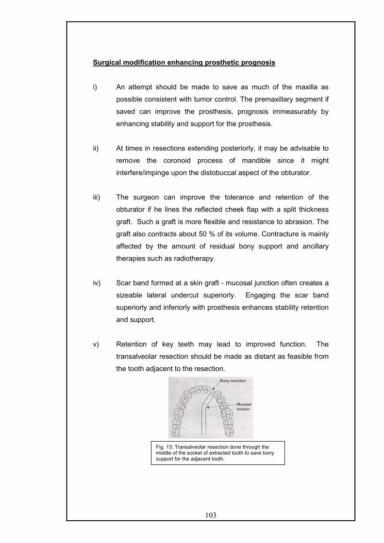
103
Surgical modification enhancing prosthetic prognosis
i) An attempt should be made to save as much of the maxilla as
possible consistent with tumor control. The premaxillary segment if
saved can improve the prosthesis, prognosis immeasurably by
enhancing stability and support for the prosthesis.
ii) At times in resections extending posteriorly, it may be advisable to
remove the coronoid process of mandible since it might
interfere/impinge upon the distobuccal aspect of the obturator.
iii) The surgeon can improve the tolerance and retention of the
obturator if he lines the reflected cheek flap with a split thickness
graft. Such a graft is more flexible and resistance to abrasion. The
graft also contracts about 50 % of its volume. Contracture is mainly
affected by the amount of residual bony support and ancillary
therapies such as radiotherapy.
iv) Scar band formed at a skin graft - mucosal junction often creates a
sizeable lateral undercut superiorly. Engaging the scar band
superiorly and inferiorly with prosthesis enhances stability retention
and support.
v) Retention of key teeth may lead to improved function. The
transalveolar resection should be made as distant as feasible from
the tooth adjacent to the resection.
Fig. 13: Transalveolar resection done through the middle of the socket of extracted tooth to save bony support for the adjacent tooth.

104
vi) If the surgeon can save some of the palatal mucosa normally
included in the resection and reflect this tissue during the bony
resection of the palate, it can be used later to cover the cut bony
margins of the palatal bones, because the defect which is covered
with keratinized mucosa is a better denture bearing surface and
can provide lateral stability.
vii) In cases where only posterior portion of the soft palate remains
post surgically, it should be removed along with the entire soft
palate because it may contract superiorly and thus hinder
prosthesis reconstruction by blocking access to the area of greatest
motion of the lateral and posterior pharyngeal walls. An exception
has to be made for edentulous patients and even posterior third of
the soft palate left behind, as the extension of the obturator
prosthesis onto the nasal side of the residual palate is an
advantage that outweighs the possible speech and leakage
problems that might occur due to the contraction.
viii) Access to the superior and lateral portions of the defect should be
provided by excision of the turbinates and the oral mucosal bands.
Maintaining the turbinate precludes the extension of the medial wall
of the obturator bulb into the nasal cavity, and the hence, it cannot
prevent the rotation of the prosthesis during function. Engaging the
Fig. 14: The remainder of the soft palate is subject to rapid contraction anteriorly and superiorly during the first three weeks after surgery and can compromise velopharyngeal closure.

105
lateral nasal side of the orbital floor provides support for the
obturator.
ix) Implants can be placed during the resective surgery in the
premaxillary segment or the tuberosity region. The use of implants
within the defect should be discouraged, as it is very difficult to
maintain hygiene around them. Also the use of pre or post
operative radiation does not preclude the use of implants it has
been found that radiation doses above 5000 centigray, compromise
the remodeling of bone around the implant and thus predispose to
bone recession and premature implant loss.
General Outline For Prosthetic Rehabilitation Of Hard Palate Defects
The prosthodontic therapy for patients with defects of the maxilla can be
arbitrarily divided into two phases of treatment with each phase having
different objectives.
I) First phase/initial phase - surgical obturator construction
II) Second phase - Definitive prosthesis construction.
I) Surgical Obturator : These prosthesis initially is limited to the
restoration of palatal integrity and the reproduction of palatal contours.
It entails the placement of a prosthesis at surgery or immediately there
after. This prosthesis must be modified at frequent intervals to
accommodate for the repaid soft tissues changes that occur within the
defect during organization and healing of the wound.
Surgical obturators are of two types according to Beumer & Curtis17
- Immediate surgical obturator
- Delayed surgical obturator / Treatment obturator/Transitional
i) Immediate surgical obturator - It is placed at the time of surgery.
It can be of utmost importance in the successful post-operative
management of person who will have resulting oral and facial
deformities.

106
Advantages of immediate surgical obturation
- Provides a matrix on which the surgical packing can be
placed.
- The prosthesis reduces oral contamination of the wound
during the immediate post surgical period.
- Enables the patient to speak more effectively
postoperatively by reproducing normal palatal contours and
by covering the defect.
- The prosthesis permits deglutition, thus the nasogastric
tube may be removed at an earlier stage.
- The prosthesis lessens the psychologic impact of surgery
by making the postoperative course easier to bear.
- The prosthesis may reduce the period of hospitalization,
Construction of immediate surgical obturators:
Beumer and Curtis17 have given several principles relative to the design of
immediate surgical obturators.
- The obturator should terminate short of the skin graft mucosal
junction. As soon as the surgical packing is removed, extension
into the defect may be accomplished with tissue treatment, or
interim soft reline materials.
- It should be simple, lightweight, and inexpensive.
- The prosthesis for dentulous patients should be perforated at the
interproximal extensions with a small dental bur to allow the
prosthesis to be wired to the teeth at the time of surgery.
Fig. 15: the cast is modified as per the out line of resection decided by the surgeon.
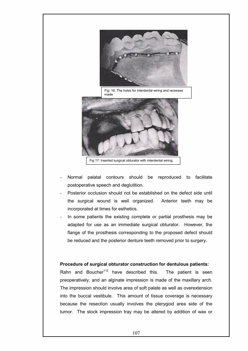
107
- Normal palatal contours should be reproduced to facilitate
postoperative speech and deglutition.
- Posterior occlusion should not be established on the defect side until
the surgical wound is well organized. Anterior teeth may be
incorporated at times for esthetics.
- In some patients the existing complete or partial prosthesis may be
adapted for use as an immediate surgical obturator. However, the
flange of the prosthesis corresponding to the proposed defect should
be reduced and the posterior denture teeth removed prior to surgery.
Procedure of surgical obturator construction for dentulous patients:
Rahn and Boucher112 have described this. The patient is seen
preoperatively, and an alginate impression is made of the maxillary arch.
The impression should involve area of soft palate as well as overextension
into the buccal vestibule. This amount of tissue coverage is necessary
because the resection usually involves the pterygoid area side of the
tumor. The stock impression tray may be altered by addition of wax or
Fig. 16: The holes for interdental wiring and recesses made
Fig 17: Inserted surgical obturator with interdental wiring.

108
removal of portion of tray to cover all desired areas or when the tumor
protrudes orally respectively. The impression is border molded in the soft
palate area by asking the patient to bend forward and then turn slowly from
side to side, causing the functional limits of the palate to be recorded.
The impression is poured in artificial stone. The area to be
resected should be determined by the surgeon and sketched onto the cast.
The teeth are removed in the designated area and eighteen gauge
wrought wire retainers or ball-type retainers are constructed on the teeth
so as to give proper retention to the completed restoration. Most of the
time a retainer is given on tooth adjacent to the defect. If conservation of
time is essential, an autopolymerizing acrylic resin can be added to the
cast by using sprinkle on technique and the cast is placed in a pressure
cooker for 10 min. If time is not a factor, the obturator should be waxed
up, to two thickness of base plate wax. Artificial anterior teeth can be
placed, if further esthetic qualities are desired and the teeth are expected
to not cause trauma to the defect area. The obturator can be invested and
processed for nine hours using hear cure acrylic resin.
A clear, heat-cure acrylic resin is usually desirable because the
pressure areas can be easily detected and relieved when the obturator is
placed immediately after surgery in the operating room.
Surgical obturator for edentulous patients.
These obturators can be constructed very easily and the procedure
is almost the same as for dentulous patients. But, since the retention is
sought from a source other than the teeth, by the technique of pinning the
obturator to maxilla using a palatal screw, suturing into surrounding
mucosa or using ligature wire around the zygomatic arch and through the
obturator is often used. This requires additional time. Some surgeons
would prefer to wait at this stage until the pack is removed and then
recommend a treatment obturator.

109
Bone screw retention for a surgical obturator in an edentulous
patient can be achieved by using a 13-16mm long self-tapping bone screw
(made of titanium or stainless steel). It is placed through a predrilled hole
in the acrylic resin plate in the mid-palate at the anterior peak of the palatal
vault and screwed into the vomer. The hole in the acrylic plate should allow
free movement of the screw before placement into the bone and must
have a countersink to hold the head of the screw. If the vomer is resected,
two screws placed at conflicting angles through the denture at the lateral
hard palate at the junction of the alveolus and palatal vaults should be
used. The contralateral maxillary sinus may be entered with the screws. A
small plug of tissue conditioner or silicone added over the head of the
screw to keep the screw attached to the plate, in case the patient
dislodges the surgical obturator.
In an irradiated patient, the placement of bone screw is avoided
and sutures placed at the periphery of the prosthesis may be secured into
the soft tissues at the height of the vestibule, against the bone of the
remaining maxillary alveolus, while the surgical side is secured against the
cheek.
The patient’s existing denture should not be used as maintaining
the occlusion while securing the obturator with bone screws, wires or
sutures is almost impossible. The patients need to be instructed to
discontinue use of the mandibular denture due to these occlusal
Fig. 18: Surgical obturator for edentulous patient with holes for transalveolar wiring and recesses for the ligature wire.
Fig. 19: Obturator in place with transalveolar wiring.

110
discrepancies. As facial contracture occurs, the anterolateral border of the
denture requires significant reduction, which involves the facial reduction of
teeth or even their removal. If it is not done then the lips unseat the
prosthesis. Therefore, the patient must be counseled to accept a baseplate
without dentition for surgical obturation.
Revision of the surgical obturator:
After the gauze pack is removed, the obturator generally needs
revision. This is accomplished by building up the defect side of obturator
in modeling plastic and border moulding the area. After this, the obturator
is invested and modeling plastic is removed and replaced with
autopolymerizing acrylic resin. In order to reduce the weight, the newly
added bulb portion may be hollowed out superiorly. This type of revision
can be performed quite easily without the patient having any discomfort.
Another technique is to do chairside incremental addition and shaping of a
tissue conditioner material. The viscous mix of the material is placed at
the periphery of the surgical obturator, arbitrarily shaped, then placed in
the mouth and patient is asked to do the movements as described later in
the impression procedure for definitive obturator. Excess material is cut
away, and after sufficient adaptation is achieved a wash type of impression
can be made by a thinner consistency of the tissue conditioner.
ii) Delayed surgical obturator/Treatment obturator:
An alternative to the placement of prosthesis at surgery is the placement of
a delayed surgical obturator 7 to 10 days post surgically. If the patient is
edentulous and the surgical defect is extensive this approach may be the
treatment of choice.
It is constructed, right after the surgical pack is removed, and about
seven days post operatively. Irreversible hydrocolloid impression is made
in a stock metal tray very carefully after covering all the margins of the tray
with beading wax. The obturator is fabricated and inserted before the
patient leaves the hospital. In dentulous patients as healing progresses,
posterior occlusal ramps can be established with the addition of
autopolymerizing acrylic resin. In edentulous patient the delayed obturator
is regularly relined. This restoration is used until the defect area has
healed sufficiently, usually about 3 months, and a more definitive obturator
can be constructed. Because, depression develops in many patients

111
during this post-operative period, a surgical obturator can have far
reaching psychological value.
Treatment obturators for dentulous and edentulous patients
These techniques have been described by Rahn and Boucher112. If the
patient has an existing denture, it can be utilized in the construction of a
treatment obturator. If there is excessive underextension an alginate
impression can be made over the denture while it is in place in the mouth.
A plaster cast is made from the impression. Cold cure acrylic resin is
added to the periphery of the old denture on the cast. The tissue surface
is cleaned and covered with resilient adhesive. The resilient denture lining
material is placed on the tissue surface and readapted. This type of
obturator can be used until a more effective treatment obturator can be
fabricated
Procedure :-
After a satisfactory impression is made, it is poured in artificial
stone. On the stone cast a pencil line can be drawn slightly inferior to
where the oral mucosa and skin graft meet on the cheek. This area can be
easily palpated on the patient as a fibrous band running horizontally on
cheek and at the height where the buccal vestibule would have been. This
band will generally extend posteriorly and become part of the posterior
portion of the defect.
After this retainers are constructed if the patient is dentulous. The
retainers should be placed as close to the defect as possible and at
maximum distance from each other135. This is different from the earlier
concept that the clasps should be placed as close to and as far from the
defect as possible (Desjardins 40). Such a configuration might not
necessarily place clasps as far apart as possible and might in fact, place a
clasp on a tooth that serves as an indirect retainer, rendering the clasp
nonfunctional.
The resin portion of the obturator prosthesis should contact the
axial surfaces of the remaining teeth whenever possible to provide
maximum stability and wider stress distribution.
The addition of teeth should be limited to satisfying esthetic needs
and assisting in speech production. Occlusal function should not be
restored.

112
Two thickness of baseplate wax is adapted over the designated
area. All undercuts alone the walls of the defect side are blocked and the
prosthesis is processed in a conventional manner. The prosthesis after
processing is checked in a patient’s mouth. The acrylic resin cavity on the
palatal side of the obturator is filled with wax until proper contour of the
palate is established. This procedure is carried out in order that an
artificial or false palate can be added to the prosthesis.
A thin layer of separating media is placed over the wax and onto
the acrylic resin. A plaster cast is then poured over the wax and extended
onto the acrylic resin to a point where reorientation of the core can be
easily done. The wax is removed from the defect side and an acrylic resin
separating medium is placed over the superior portion of the core. Over
this core is sprinkled auto-polymerizing acrylic resin to a thickness of 1-2
mm. The core is then invested and pressed into contact with the
prosthesis and hold firmly till resin has set properly.
All excess acrylic resin is trimmed away and the obturator is
polished. Some dentists may prefer to wax the defect side so that it will be
processed entirely of resin and then hollow it out as a port of revision
procedure.
The patient is examined periodically and instructed regarding
maintenance and cautioned that further adjustments are likely as the
surgical area heals and contracts.
Interim Obturation: bridges the gap between immediate surgical obturator
and the definitive prosthesis. There is very little distinction as both
immediate and interim obturators provide comfort and function to the
patient till definitive obturation can be done.
The reasons for fabricating a new prosthesis are:
- The periodic addition of interim lining materials increases the bulk and
weight of the obturator and the temporary material become rough and
unhygienic with time.
- Addition of teeth to the obturator provides great psychological relief to
the patient.

113
- The retention and stability can be made better than the immediate
obturator.
- The interim prosthesis may prove useful as a backup prosthesis to the
definitive one.
Instructions to patients for delayed surgical and interim obturators:
- The patient should be instructed not to keep the obturator out for more
time than is required to clean the prosthesis or the surgical defect area
as ensuing tissue edema may alter the fit of the prosthesis.
- Denture adhesives can be used with acrylic resin dentures not lined by
tissue conditioner.
- Patients must be instructed and made to practice the placement &
removal of the prosthesis and instructions for cleaning the prosthesis
must be given before the patient leaves the office.
- Patients should be told that the head- upright position during
swallowing would decrease the leakage of fluids into the nose.
- Patients should be instructed not to use effervescent denture cleaners
when tissue conditioner material is used to reline.
II) Definitive Obturation
Three to four months after surgery consideration may be given to
the construction of definitive obturator prosthesis. The timing will vary
depending on the size of the defect, the progress of healing, the prognosis
for tumor control, the effectiveness of the present obturator, the use and
timing of post surgical radiation therapy and the presence or absence of
teeth. The defect must be engaged more aggressively for edentulous
patients to maximize support, retention and stability.
Therefore the recovery period is extended for these patients, as changes
associated with healing and remodeling continue to occur in the border
areas of the defect for at least one year, but are primarily related to the
peripheral soft tissues rather than to the bony support areas.
If osseointegrated implants are placed at the time of the tumour resection,
fabrication of the definitive prosthesis is delayed until the implants are
exposed and peripheral soft tissues around them have healed.
Also the information regarding the prognosis of the tumour control as well
as general health and desires of the patient need to be considered.

114
A patient's poor prognosis, or poor health does not preclude the
construction of definitive obturator prosthesis, but the treatment plan
should reflect the possible altered needs of such a patient.
Treatment Concepts Regarding The Definitive Obturator Prosthesis:17
Following factors should be considered.
i) Movement of the Prosthesis: The obturator prosthesis will be
displaced superiorly into the defect with the force of mastication and will
tend to drop without occlusal contact. The degree of movement will vary
with the number and position of teeth that are available for retention as
well as with the size and configuration of the defect.
ii) Tissue changes: Dimensional changes will continue to occur for at least
a year secondary to scar contracture and further organization of the
wound. Movement of the prosthesis, during function may, itself contribute
to tissue changes. Hence, the obturator portion should be made in acrylic
resin so as to facilitate reline or rebasing to compensate for these
changes.
iii) Oro-Nasal Partition: Obturators for acquired defects of the maxillae
are basically covering prosthesis serving primarily to re-establish the oral
nasal portion. The obturator prosthesis is extended into the defect in order
to enhance retention, stability and stability. The contours of the defect are
relatively static during function, aside from the movement of the soft tissue
displaced by the movement of the coronoid process, the anterior border of
the ramus, elevation of the soft palate and slight movement of the lips and
cheeks. In contrast, obturators that restore palatopharyngeal incompetency
must function in concert with tissues exhibiting extensive functional
movement.
iv) Extension into the defect: is dependent on the requirements of
retention, stability and support. If adequate maxillary structures are
present, extension into the defect need not be extensive. In addition the
extension of the prosthesis into the defect will vary according to the
configuration of the defect and the character of its lining tissue. Extension
of the prosthesis superiorly along the nasal septum offers little mechanical
advantage. In addition its lining mucosa is not amenable to tolerate stress.

115
In comparison, extension superiority along the lateral margin of the defect
will enhance, retention stability and support. Stress is well tolerated by the
skin graft and the oral mucosa lining the cheek surface of the defect.
v) Teeth: The presence of teeth enhances the prosthetic prognosis.
Every effort should be made to maintain and enhance the longevity of
teeth, or even roots of teeth, to assist in the retention, stability and support
of the prosthesis.
vi) Implants: The placement of osseointegrated implants dramatically
improves the function of obturator prosthesis. Implants can be placed
either at the time of tumour resection or at some appropriate time
thereafter.
vii) Weight: Bulky areas should be hollowed out to reduce weight so that
teeth and supporting tissues are not stressed unnecessarily especially
when the obturator prosthesis is suspended without bony or posterior tooth
support on the defect side. Wu and Schaaf153 have found that hollowing
the obturator prosthesis reduces weight by 7-33% depending on the size
of the defect. The superior surface can either be left open or closed.
Clinicians who prefer closed top state that if the obturators are left open,
nasal secretions accumulate leading to bad odour and added weight.
Advantages of leaving the top open are that the weight of the obturator is
further reduced as there is no lid, it is easier to adjust and speech is better.
The effect of length of extension into the defect and top configuration
(open/closed) was studied by Aramany and Drane (1972) and Oral96; and
they found that the speech quality using the limited extension prosthesis
was better than with the maximally extended obturator prosthesis. The
lengthy superior extension along the lateral and disto lateral aspect of the
defect is essential for stability, support and retention. If a lid is added to the
hollow obturator, the obturator bulb occupies significant portions of the
nasal and maxillary sinus cavities.
Sharry(1962) has stated that it is not necessary for the obturator to occupy
the entire defect superiorly for effective obturation.
If a closed bulb is used, then it may change the configuration,
resonance balance and airflow characteristics of the nasal cavity. The

116
open obturator design may be less obtrusive in the nasal cavity and
permits more normal airflow, nasal resonance and speech.
Though Chalian29 recommends closed top obturator, Beumer and
Curtis17 advocate the open top obturator and have experienced that
occasionally a patient may be required to be converted to closed top bulb.
Also, a drainage channel for the collected secretions may be made. A
diagonal opening may be made in the inferolateral floor of the open
obturator through the cheek surface for drainage154. The cheek will close
against the opening and hence, the seal will not get compromised. A pipe
cleaner can be used to maintain patency and cleaning this channel.
Definitive Prosthesis construction for hard palate defects is divided
into
A) a) For Edentulous patients
b) For Dentulous patients
B) a) For total Maxillectomy
b) For Partial Maxillectomy
PROSTHETIC CONSIDERATIONS FOR EDENTULOUS PATIENTS
WITH TOTAL MAXILLECTOMY DEFECTS
It is a prosthodontic challenge to restore such patients as air leakage, poor
stability and support, reduced bearing area compromise adhesion,
cohesion and peripheral seal. Therefore, the contours of the defect must
be used to maximize retention, stability and support.
The prosthesis exhibits a lot of movement about the axis of rotation, which
is located along the medial palatal margin of the defect.
In a posterior maxillary defect, where the premaxilla is preserved, the axis
of rotation shifts posteriorly. This is a favourable situation as more support
is available.
- Remaining palatal structures determine the available support and
stability. An ovoid or square arch form provides better support than the
reduced amount and undesirable angulation of the palatal shelf found
in tapering arches. If pendulous soft tissues are present, they should
be excised to improve the prognosis.
- The undercut above the scar band at the junction of the split skin graft
with the oral mucosa should be engaged to enhance retention and

117
support of the prosthesis. Since, the lateral portion of the obturator
exhibits greatest degree of movement, retention can be improved by
appropriate obturator tissue contact supero-laterally.
- Additional retention gained by extending the prosthesis along the nasal
surface of the soft palate or anteriorly into the nasal aperture.
- The lateral portion of the orbital floor can also gain support if it has
been lined by skin graft.
- Impressions are made as described later.
- Jaw relations may need to be recorded on processed bases as
described by Curtis 35 & Jacob 61as support and stability are difficult to
achieve with a conventional temporary base. Temporary base can be
used if stability and support is adequate. Trismus complicates the
recording of vertical relation. It can be countered by the use of flexible
baseplate type of plate made of silicone as described by Lauciello.
However, it is subject to rapid deterioration and fungal infections, it
needs to be replaced frequently. Extreme trismus can also be
managed in a way described by Taylor in a patient with a contiguous
orbital defect. The prosthesis is button shaped and fabricated in
silicone. It is snapped in position from the top to plug the defect. It is
possible only when the orbital defect is large.
Normal parameters are used to adjust the maxillary rim and the vertical
dimension. Compensation for the contracted lip and cheek has to be
done on the surgical side. Often it may be necessary to gradually
create a negative horizontal overlap or end-to-end occlusion extending
from the midline to the posterior dentition. Lip closure may be a
problem due to contracture and shortening of the upper lip. It can be
compensated by reducing the vertical dimension slightly or by the
adjustment of buccolingual placement of teeth. The latter should be
preferred as if the former technique is employed; there might be tongue
or lip biting on the normal side.
- Due to the size of the maxillary cast a high post articulator such as
TMJ articulator is recommended. Transfer should be done with a face
bow record.
- Graphic centric records by intra or extra oral tracing are
contraindicated as the lack of support introduces inaccuracy. Use of
bite registration paste to record the centric relation is advocated along
with stabilization of the record bases by the operator during closure.

118
The maxillary base should be carefully observed for movement or
shifting during interocclusal record making.
- Teeth should be arranged using Monoplane teeth with reduced size to
minimize stress 25. Monoplane teeth also allow negative horizontal
overlap on the surgical side. Roberts advocated balanced occlusion
while according to Beumer & Curtis nonanatomical and /or functional
posterior teeth are arranged according to neutrocentric or lingualized
occlusal concepts as these minimize lateral forces and deflective
occlusal contacts and thus improve stability. The teeth are set in
centric relation and all lateral interferences eliminated. The trial denture
is checked and jaw relations verified.
- At the try-in appointment the palatal contours must be evaluated. The
vault may be too high or low. It can be evaluated easily by sweeping
the thumb across the palate from one side to the other. Palatograms
can be used to evaluate further. Pressure indicating paste is streaked
across the palatal contour and then the patient is asked to swallow and
speak. Heavy contact areas should be trimmed while the deficient
areas built up in wax. If there is heavy tongue contact on the palatal
surface of the teeth on the defect side, tongue space should be
regained by reducing the width of the occlusal surfaces.
- The denture can be made hollow, with a closed or open top, or have a
silicone obturator section as described later in the different techniques
that are used.
- Denture processing should be done at 165 F for 15 hours to prevent
porosity if thicker sections of acrylic are present. If the processed
bases were used then the prosthesis can be cured at a lower
temperature than the first curing .The clinical significance of the
distortion created with multiple processing of the resin is negligible.
- During denture delivery pressure indicating paste should be used to
delineate areas of excessive tissue displacement. Clinical remount
should be done to perfect occlusion.
Instructions to the patients:
- Patients should continue to wear the maxillary prosthesis at night as
the sinus secretions and saliva cannot be managed without it. If not

119
worn then tissue edema at the periphery of the defect will cause
difficulty in placement of the prosthesis.
- Patients should be instructed to masticate from the nonsurgical side of
the arch in cases where the surgical defects are very large.
- Patients should be taught how to use denture adhesives and to
maintain hygiene of the prosthesis.
PROSTHETIC CONSIDERATIONS FOR EDENTULOUS PATIENTS
WITH PARTIAL MAXILLECTOMY DEFECTS
These are similar to the total maxillectomy patients, however the prognosis
is better as more of the hard palate remains and hence, the prosthesis has
more stability and support. However, the retention may be compromised
as the access to and use of the defect is more limited. Implants are
especially useful for this group of patients as the premaxillary segment is
available for placement of implants and as the access to the defect may be
difficult.
PROSTHETIC CONSIDERATIONS FOR DENTULOUS PATIENTS WITH
TOTAL MAXILLECTOMY DEFECTS
Treatment concepts – These are concepts that are unique for dentulous
patients and should be considered by the prosthodontist.
i. Location of the defect – The tumour location and size will dictate the type
of remaining arch following resection of maxillary tumors. Invariably, the
surgical resection includes the distal portion of the maxilla and rarely does
a distal abutment tooth remain after surgery. The extent of the surgical
resection anteriorly does vary considerably. Therefore, a Kennedy class II
partial denture with an extensive lever arm is required for most patients.
ii. Movements of the prosthesis – With resection of the maxilla the mucosal
and bony support are compromised or may be lacking completely. Hence,
the defect must be employed to minimize the movement of the prosthesis
to reduce the stresses on the abutment teeth. In most defects, if forceful
mastication occurs on the defect side, the prosthesis can be displaced
significantly into the defect, which causes the abutment teeth to be

120
exposed to damaging lateral torquing forces. The lateral portion of the
obturator exhibits the greatest motion; retention can be improved by
appropriate obturator tissue contact supero-laterally.
iii. Length of the lever arm – In conventional prosthodontics, the most
common Class II removable partial denture involves an edentulous area
distal to the cuspid. However, considerably longer lever arms are
encountered in patients with intraoral surgical defects. It is not uncommon
for the defect to extend form the middle anteriorly into the soft palate area
posteriorly.
iv. Arch form – Square or ovoid arch forms possess more palatal bearing
surface perpendicular to occlusal stresses. This results, in a more stable
prosthesis during function. This support area must be utilized by the
prosthodontist in the same manner as the buccal shelf is used for support
for the mandibular partial prosthesis. Tapering arch form provides less
palatal support area; therefore, support is compromised possibly leading to
Fig. 20: Illustration showing the greatest motion in the lateral portion of the obturator.

121
significant rotation and subsequent movement of the prosthesis up into the
defect, during mastication.
v. Teeth – Preservation of the remaining teeth is of particular importance,
because retention of the prosthesis is far less in the corresponding
edentulous patient. Partial denture designs must anticipate and
accommodate to the movements of the prosthesis during function without
exerting pathologic stresses on the teeth. Maximum retention, stability and
support should be derived from the defect and close attention should be
directed to the occlusion on the defect side to minimize occlusal forces.
vi. Partial denture design: The basic principles should be followed.
- Major connectors should be rigid.
- Occlusal rests should direct forces along the long axis of teeth.
- Guide planes on the palatal surfaces facing the defect to be used to
facilitate stability and bracing on maximum teeth possible as it resists the
rotational dislodgement of obturator. The longer the guide planes, better is
the resistance to rotational dislodgement. These can be incorporated in
the cast crowns, casted bonded metal contours or bonded resin contours.
- Retention should be within physiological limits of the periodontal ligaments
of the remaining teeth. The retainers should be placed as near to the
defect and as far away from each other.
- Maximal support and stability should be gained from the residual soft
tissue denture base area including the defect.
PROSTHETIC CONSIDERATIONS FOR DENTULOUS PATIENTS WITH PARTIAL MAXILLECTOMY DEFECTS
These are similar to those for total maxillectomy patients, but these have
better prognosis as the margin of resection moves posteriorly. With the
preservation of the canine or even the lateral, the advantages are
dramatic as the fulcrum line shifts posteriorly. As this happens the
distolateral extension of the obturator should be lengthened for better
mechanical advantage as it will be at a right angle and most distant to the
fulcrum line. Indirect retainers should be placed as far anteriorly as
possible from the fulcrum line. Retainer placed on the tooth adjacent to
the defect increases stability and retention. The construction for the

122
prosthesis is similar to total maxillectomy patients, however when the
defects are very small, they should be packed with gauze, to prevent
escape and lodgment of the impression material. Occasionally,
edematous turbinates extend into the oral cavity, which should removed
surgically before the prosthesis is made.
CLASSIFICATION OF PARTIALLY EDENTULOUS DENTAL ARCHES
WITH MAXILLECTOMY DEFECTS:
Defects of the partially edentulous patients have been categorized into 6
groups by Aramany (1978)7 based on the relationship of the defect area to
the remaining abutment teeth. Class sequence reflects the frequency of
occurrence in a patient population of 123 patients treated during a period
of over 6 years.
Class I: The resection in this group is performed along the midline of the
maxilla, with the teeth maintained on one side of the arch. This is the most
frequent occurring defect and most patients falls into this category.
Class II: The defect in this group is unilateral, retaining the anterior teeth
on the contra lateral side. This type of surgical resection is favoured more
rather than the classical maxillectomy. The central incisors and sometimes
all the teeth anterior to canine or premolar are saved.
Class III: The palatal defect occurs in the central portion of the hard palate
and may involve part of soft palate. The surgery does not involve and
remaining teeth.
Class IV: The defect crosses the midline and involves both sides of
maxilla.
Class V: The surgical defect in this situation is bilateral and lies posterior
to the remaining abutment teeth.
Class VI: It is rare to have an acquired maxillary defect anterior to the
remaining abutment teeth. This occurs mostly in trauma or congenital
defects rather than as a planned surgical intervention.
This classification excluded patients who have large palatal defects
involving both sides of the dental arch and those who have only one tooth
remaining. For these patients, the principle of design is similar to that for
edentulous maxillectomy patients. The remaining teeth or tooth are
reduced in height to improve the crown- root ration and support is derived
primarily from the residual soft tissue. These teeth are either covered by an
overdenture or clasped with a flexible wrought wire clasp.

123
DESIGN OF THE METAL FRAMEWORK FOR PARTIALLY
EDENTULOUS MAXILLECTOMY DEFECTS- ARAMANY (1978) 8
The design of the metal framework obturator will vary greatly is each
group. However, the design objective is to select most suitable
components to resist various forces without applying undue stress on
remaining teeth and soft tissues. The patterns of forces affecting the
obturator prosthesis are complex because of their concurrent occurrence.
These forces may be categorized as vertical dislodging forces, occlusal
vertical force, torque or rotational lateral force and anterior posterior forces.
The weight of the nasal extension of the obturator exerts dislodging and
rotational forces on abutment teeth. Obviously, then it would be desirable
that the nasal extension superiorly helps resist such forces.
Occlusal vertical force is activated during mastication and swallowing.
Wide distribution of occlusal rests will help counteract such forces.
Preservation of teeth or part of residual ridges across the midline will
greatly improve obturator stability. Maximum support should be planned
through utilization of full palatal coverage. Lateral forces are minimized by
proper selection of an occlusal scheme, elimination of premature, occlusal
contact, wide distribution of stabilizing components, and covering medial
wall of the defect with palatal flap, can help resist lateral forces. Guiding
planes on the proximal abutment teeth help resist anterior-posterior
movement. Properly designed retainers will reduce stress transmitted to
the abutment teeth’s while maintaining obturator in place. Stabilization and
indirect retention components must be strategically positioned to effectively
retard movement of the nasal extension portion away from its terminal
position, which in turn will reduce stresses on the abutment teeth.
CLASS I
The design can be either linear when the remaining anterior teeth were not
to be used for retention and support and a tripodal design when the
anterior teeth were used.
Class I – Curved arch form:
Support: It is provided and shared by the remaining natural teeth, the
palate and any structure in the defect that may be contacted for the
purpose. The goal is to ensure that the functional load is distributed as
equally as possible to each of these structures via a rigid major connector.
The natural teeth are aided in this action, when the support regions of the

124
palate and the defect are loaded to their maximum without physiologic
overload.
A broad square or ovoid palatal form aids by providing greater tissue
bearing surface to resist upward force (occlusal force) and a greater
potential for tripodization to improve leverage. A tapering arch is less of an
aid. Rests are placed on the most anterior abutment (closest to the defect)
and the mesio occlusal surface of the most distal abutment tooth when the
alignment and occlusion will permit. The mesio-occlusal posterior rest,
most often located between adjacent posterior teeth, is accompanied by a
rest on the disto-occlusal surface of the more anterior adjacent tooth. This
additional rest will prevent wedging and separation of the two adjacent
teeth and will decrease the possibility or periodontal damage from food
impaction. The completed obturator often requires a compound path of
insertion as undercuts and support regions within the defect will be
negotiated before the teeth are engaged. Guide planes will assist in the
precise placement of the prosthesis once the teeth are contacted. They will
also ensure more predictable retention and add a greater stability to the
prosthesis. Guide planes on the anterior abutment should be kept to a
minimum vertical height (1-2mm) to limit torque to the abutment teeth and
should be physiologically adjusted. This is important as movement can be
expected during function because of the extensive lever arm provided by
the defect and the dual nature of the support system. This consideration
becomes more important as the curvature of the arch decreases and the
potential mechanical advantage of the indirect retainer is decreased. In
this instance, it is especially important to use the palatal surfaces of the
posterior teeth for additional bracing and stability.
An indirect retainer is usually located perpendicular to the fulcrum line
(which connects the most anterior and posterior rests) and as far forward
Fig. 21: Class I

125
as possible. This is usually a canine or a first bicuspid. Strategically placed
indirect retainers allow maximum use of leverage to resist movement of the
prosthesis in a downward direction by the pull of gravity acting on the
defect side.
Retention: It is supplied by direct retainer designs that allow maximum
protection of the abutment teeth during functional movements. On the
anterior abutment, a 19 or 20 gauge wrought wire clasp of the “I- bar”
design is often used to engage a 0.25 mm undercut on the midlabial
surface of this abutment or a gate design. Additional protection is afforded
to this tooth by splinting it to one or two adjacent teeth with full crowns
whenever possible or acid etch composite resin techniques when crowns
are not possible. Other possibilities include a variety of cast clasp
assemblies located on the height of contour for frictional retention only.
The posterior retainer is most often a cast circumferential clasp utilizing a
0.25 mm undercut on the buccal surface. The placement of posterior
clasps facing in both anterior and posterior direction will aid in retaining
both anterior and posterior portions of the prosthesis.
CLASS I : LINEAR ARCH FORM
The linear design is used for a class I defect when one does not desire to
use the anterior teeth, when the arch form is linear and the remaining
posterior teeth are in a relatively straight line.
Support: in the linear design the remaining posterior teeth and the palatal
tissues provide support. The palate becomes more important in the linear
Fig. 22: Class I

126
design because the use of leverage to resist vertical dislodging forces is
decreased.
Miller states that a unilateral design requires bilateral retention and
stabilization on the same abutment teeth. A diagonally opposed retention
and stabilization system can be used.
Retention: is provided by the combined use of buccal premolar retention
and palatal molar retention. Stabilizing components are placed on the
palatal surfaces of the premolars and buccal surfaces of molars.
CLASS II DESIGN : In this, the design is similar, to Kennedy’s class II
removable partial denture. A bilateral tripodal design is recommended.
Primary support is placed on the tooth nearest the defect, as well as the
most posterior molar on the opposite side. Double rests are used on
adjacent posterior teeth. Guide plane location and size is similar to the
class I situation with full use of the palatal surfaces of the posterior teeth.
Guiding planes are located proximally on the distal surface of anterior tooth
and the last molar. Retention and stabilizing components are placed on
buccal and palatal surfaces of abutment teeth respectively.
The abutment tooth closest to the defect is critical to for retention and
should be engaged with a direct retainer design that resists downward
displacement but tends to rotate, disengage or flex when upward forces
are applied. A cast circumferential clasp or an I-bar clasp is frequently
used in a 0.25 mm undercut when the retentive terminus can be located on
the fulcrum line. A 19 gauge wrought wire clasp in a 0.5 mm or less
mesiofacial undercut is also a frequent choice. Additional protection can be
provided for this tooth by splinting it to one or two teeth adjacent to it. The
posterior retainer is most frequently a cast circumferential clasp using a
0.25 mm distobuccal undercut. The placement of posterior clasp
Fig 23: Class II

127
assemblies facing in both an anterior and posterior direction will aid in
retaining both the anterior and posterior portions of the prosthesis. The
anterior facing clasp will also serve to aid any additional clasps placed
opposite to the fulcrum line from the defect. The canine is frequently the
location of an indirect retainer and also serves as an additional (optional)
retentive site, engaged with a 19 gauge wrought wire clasp in a 0.25 mm
undercut. The canine is important in resisting occlusally directed forces
and will receive severe stress. If an additional clasp is required on the
canine, it should be a more flexible clasp in less than the normal amount of
undercut or a less flexible clasp on the height of contour so that frictional
retention will be supplied.
A combination of buccal and palatal retention is almost never indicated for
this classification for the following reasons:
a. Additional bracing and cross arch stabilization will be lost when palatal
retention is engaged.
b. Increased rotation will be noted with an actual decrease in retention
because of the short length and shallow gingivally located curvature of
the palatal surfaces of the molar teeth and disengagement of the
lingual undercut on slight displacement.
c. The location of palatal retentive clasps often results in a major
connector that has multiple small regions that trap food or irritate the
tongue.
Occlusion on the defect side is important because the occlusally
directed forces can be destructive. Occlusal schemes with fewer,
smaller teeth, located further toward the anterior side and devoid of
premature or deflective contacts is desirable.
CLASS III DESIGN : The design is based on quadrilateral configuration.
The remaining natural teeth via widely separated and bilaterally located
rests supply support. The canines and molars are usually selected to
generate the largest quadrilateral shape possible while avoiding alignment,
occlusion and hygiene problems and providing good aesthetics. Little or no
support is derived from the palate or the defect. Bilateral symmetry of the
major connector design and avoidance of the rugae area is desirable when
possible.

128
Guide planes are usually short because they are located on the palatal
surfaces of the posterior teeth. The proximal surfaces may be liberally
used if edentulous spaces are present. Very little movement of the
prosthesis should occur in function, therefore these guide planes may be
long and physiological adjustment may not be necessary.
Indirect retention is not required because a direct retainer supports each
terminus; therefore, rotation around a common fulcrum should not occur.
Retention is often provided with cast retainers using 0.25 mm undercuts on
the facial surfaces of the teeth. These may be circumferential retainers, I
bars or modified T-bars depending on the location of the retentive sites,
the esthetic requirements and the presence of tissue undercuts.
Combination type retainers can be used to an esthetic advantage because
they can engage a deeper undercut and may thus be placed in a less
conspicuous zone.
CLASS IV DESIGN : The design is linear, Support is located on the centre
of all remaining teeth. Channel rests or multiple mesio-occlusal and disto
occlusal rests are designed. The defect should also be engaged to use, as
much as possible, any sites within the defect that may be contacted. These
are the midline of the palatal incision, when palatal mucosa has been
preserved to cover this region, the floor of the orbit, the bony pterygoid
plates and the anterior surface of the temporal bone. If these regions are
covered by respiratory mucosa, little added support can achieved.
Retention is located buccally on the premolars and palatally on molars.
Stabilizing components are palatal on premolars and buccal on molars.
This leads to loss of bracing, increased rotation and the creation of small
irritating spaces in the major connector. (As discussed in Class II design)
Fig. 24 Class III

129
Retentive sites should ideally be located on teeth and the lateral wall of the
surgical defect via the superolateral extension of the obturator section in
the engagement of the lateral scar band.
Reduced posterior occlusion (size and number of teeth) is also useful.
If no lateral scar band exists, because a split thickness skin graft was not
given or because one could not be maintained, the prosthodontist may
have no choice but to use a combination of buccal and palatal retention.
CLASS V DESIGN :
In this, splinting of at least two terminal abutments on each side is
suggested.
Rests located on the mesio occlusal surfaces of the most posterior
abutment provide support. These rests define the fulcrum line around
which most of the expected movement will take place. If adjacent posterior
teeth are involved, double rests are used. Stabilization and bracing is
provided by broad palatal coverage and contact with the palatal surface of
the remaining teeth.
Fig. 25: Class IV

130
Indirect retention is provided by rests located as far forward of the fulcrum
line as possible. This usually places them on central incisors, which often
presents an occlusal problem that may require minor occlusal equilibration.
The location of the indirect retainer essentially converts the design to an
efficient large tripod that uses leverage to resist downward movement of
the prosthesis. Positive rest seats are a critical necessity to eliminate the
strong labial force generated by the downward movement of the
prosthesis.
Retention: I-bar clasps are placed bilaterally on the buccal surfaces of the
most distal teeth. Located in a 0.25 mm midbuccal undercut very close to
the fulcrum line, it provides for resistance to dislodgement and rotation in
function. When the remaining soft palate is scarred and relatively immobile
it can also be used to provide added retention for the posterior portion of
the prosthesis. A gate prosthesis is a viable alternative for these patients
if they can tolerate splinting of all of the remaining teeth.
CLASS VI DESIGN :
In such defects, two anterior teeth are splinted bilaterally and connected
by a transverse splint bar. A clip attachment may be used with out an
elaborate partial framework. If the defect is large, or remaining teeth are in
less than optimal condition, a quadrilateral configuration design is followed.
In this the support is derived from rests located on the anterior and
posterior abutment teeth. Greater stability is provided by placing additional
rests as far posteriorly as possible. The most posterior rests, similar to the
Kennedy Class IV situation, may be considered as indirect retainers,
Fig. 26: Class V

131
resisting the vertical downward movement of the anterior segment of the
prosthesis.
In extremely large Class VI situations indirect retention may not be
possible. The remaining natural teeth provide all of the support with little
support derived from the defect. Guide planes are usually located on the
proximal surfaces adjacent to the defect and should be kept of minimal
length (1-2mm) to avoid trauma to the abutment teeth during expected
movements of the prosthesis.
Retention is most often provided simply with cast retainers using 0.25 mm
of facial undercut. I bar or combination retainers can be used on anterior
abutments.
Effective accessory retention can be achieved by extending the prosthesis
anteriorly into the nasal aperture. Cosmetic support of the nose and upper
lip is also possible when adequate retention is present.
Fig. 27: Class VI

132
OTHER DESIGN CONSIDERATION'S FOR PARTIAL DENTURE
FRAMEWORK FOR OBTURATOR PATIENT
i) Stress breaker concept
Since the maxillofacial prosthetic patient has an added problem of movable
basal seat, which is made up of grafted bone and skin covering over it
(instead of mucous membrane). So there is more movement of the base
in function than severely resorbed alveolar ridge. Also, the restoration of
the lost parts is usually heavy and bulky, and this adds to the load on the
remaining teeth.
The remaining teeth in these patients are extremely valuable to them and
stress breaking should be considered.
a) When relatively few teeth are left and a partial denture is indicated,
the combination clasp that Applegate described with one arm
consisting of a flexible wrought wire and the opposing arm
consisting of a rigid cast arm should be considered. The wrought
arm supplies gentle retention and the cast arm is kept out of the
undercuts and serves only to stabilize the appliance against lateral
movements.
b) A double or split-bar type of stress breaker is effective where the
abutment teeth are all posterior to the denture base. This design
prevents rotation about the anterior rest. The great advantage of
such a split bar is in its ability to transfer the fulcrum or center of
rotation to the most posterior tooth.
c) The truss bar retainer is indicated, where a large number of healthy
teeth remain and maximum retention is needed to support an
obturator or other large appliance.

133
II) SWING LOCK PARTIAL DENTURE FRAMEWORK DESIGN
CONCEPT - Javid & Dadmanesh (1976) 63
The lack of a residual alveolar ridge and soft palate in hemimaxillectomy
patients complicates the design of removable partial dentures for these
patients. With conventional clasp design, because of the lack of the
supporting residual alveolar ridge the prosthesis moves towards the tissue
more than the conventional removable partial dentures. Also during
masticatory function, depending on the magnitude of forces, kind of food
and the size of the occlusal table, the retentive clasp arm might be bent or
broken. As a result, the prosthesis may lose its retention and stability,
affecting speech as well.
A swing lock - design for clasp retention of the obturator prosthesis is
suggested. A “gate clasp” was first described by Ackerman in 1955 and
swinglock concept was introduced by Simmons in 1963.
The design should include multiple retentive bar clasps engaged in the
appropriate undercuts (0.010 inch) utilizing as many teeth as possible. This
kind of design may have an orthodontic effect, depending on the size of
the occlusal table, degree of masticatory forces, and the number of teeth
involved in retention. The reduction of the amount of masticatory force is
not possible but the resisting force should include as many teeth as
possible.
This concept has been used in the fabrication of a surgical obturator by
William Black (1992) 19
Technique: On the preoperative casts the outline of resection is marked. A
0.036 wire is contoured into a double arch wire across the buccal surfaces
of the remaining teeth. Posteriorly the wire is passed through a 0.51-inch
inner diameter steel tubing to provide a hinge axis. Anteriorly, the wire
ends are looped to provide for elastic anchorage. After blockout, a custom
swinglock gate of autopolymerizing acrylic resin is made. This is
incorporated in the remaining prosthesis. At the time of surgery this is
placed and gate retention is either obtained by elastics or wire. Even
interdental or suspension wiring can be done to retain. After a week
following surgery the prosthesis is relined, the interproximal holes are filled
and the prosthesis is used as a removable prosthesis with gate retention

134
till a definitive obturator can be made. The advantage is that there is easier
transition from wire stabilized to removable obturation.
Marunick (2004) 80 described a hybrid gate design framework, which
incorporates both conventional retainers as well as the gate design
concept.
III) DUAL PATH OF INSERTION CONCEPT – King & Gay 49
Patients with an acquired maxillary defect, have essentially a unilateral
support problem that is compounded by the need to support the obturator
portion of the prosthesis. The use of facial and lingual retentive arms has
been the classic way of designing unilateral removable partial dentures.
The use of facial retentive and lingual reciprocating arms is based upon
the premise that there will be cross-arch clasping. When it is impossible to
provide cross-arch clasping, as in maxillectomy, a unilateral support
situation exists, and the value of using both facial and lingual retention in
the same arch becomes apparent. The obturator's downward movement
can be resisted by the lingually placed clasps on the supporting teeth, as
well as by the soft tissues that approximate its lateral border.
The dual path of insertion is a reliable concept that can be of great value in
obtaining retention with a guiding plane when that plane has access to an
undercut before final seating of the prosthesis. When a lateral or central
incisor is the posterior abutment on the defect side of a maxillectomy
patient, the dual path may allow retention to be obtained with the guiding
plane and obviates the need to clasp the teeth.
Fig. 28: A hybrid gate prosthesis
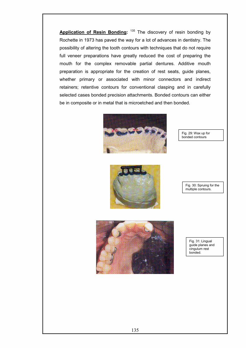
135
Application of Resin Bonding: 135 The discovery of resin bonding by
Rochette in 1973 has paved the way for a lot of advances in dentistry. The
possibility of altering the tooth contours with techniques that do not require
full veneer preparations have greatly reduced the cost of preparing the
mouth for the complex removable partial dentures. Additive mouth
preparation is appropriate for the creation of rest seats, guide planes,
whether primary or associated with minor connectors and indirect
retainers; retentive contours for conventional clasping and in carefully
selected cases bonded precision attachments. Bonded contours can either
be in composite or in metal that is microetched and then bonded.
Fig. 29: Wax up for bonded contours
Fig. 30: Spruing for the multiple contours.
Fig. 31: Lingual guide planes and cingulum rest bonded.

136
Precision & semi precision attachments:
Bonded attachments are indicated in cases where the terminal abutment does
not lend itself to conventional clasping. For e.g. when a central or lateral incisor
is next to a large defect. Attachments that permit some measure of rotational
freedom are most appropriately selected. The life of the attachment can be
increased when the attachment does not become the rest s well as the
retentive component. Milled rest seats developed on the casting that holds the
attachment allow the stress to be transferred to the long axis of the abutment
rather than to the cantilevered extra-coronal attachment.
Fig. 32: Definitive obturator in position.
Fig. 33: Wax up of multiple guide planes with CEKA attachment on central incisor.
Fig. 34: obturator casting seated on master cast. The plate of the framework rests on solid rest seats placed in the anterior bonded castings.

137
PROSTHESIS DESIGNS FOR OTHER ACQUIRED MAXILLARY
DEFECTS as described by Chalian 29
1) Snap on prosthesis for marginal defects.
When there is a marginal defect of the maxilla but with no associated
palatal or vestibular communication with the maxillary sinus cavity, a snap
on removable partial prosthesis may be constructed for retention and
esthetic purpose.
2) Snap on Prosthesis for Anterior segmental defect.
The versatile snap-on mechanism can also be adapted to provide
transpalatal splinting when the anterior palatal defect is large. To minimize
tilting, looseness, and occlusal stress on the remaining teeth, a clip
attachment is centrally placed to engage the palatal rod.
3) Prosthesis for lateral segmental defects of edentulous maxilla with no
palatal opening. Often trial dentures are made to permit the patient to have
a positive experience of closure and centric stop for occlusion. Then,
when facial symmetry and patient comfort have been achieved, the final
prosthesis is fabricated.
ADVANCES IN SURGICAL RECONSTRUCTION AND ITS IMPLICATION
ON MAXILLOFACIAL REHABILITATION 94
New prosthodontic guidelines that relate to the surgical reconstruction of
the maxilla seem to be mandated as a result of advances in microvascular
surgical techniques. Microvascular free flap surgery allows the transfer of
muscle, connective tissue, skin and bone to the recipient sites. A vascular
supply to the graft can be provided after donor blood vessels are re-
anastomosed to recipient vessels of the head and neck region.
Fasciocutaneous and osteomyocutaneous free flaps can provide closure
of the oral cavity for acquired maxillary defects.
Major factors in the prosthodontic rehabilitation decision-making process
include whether a maxillectomy defect should be reconstructed; if so, what
type of free flap should be employed; and how the chosen free flap will
affect the patient’s oral function.

138
Okay et al state that soft tissue flaps can provide closure of the oral cavity
in smaller defects but are unsupported and may not provide a stable
palatal base for a removable prosthesis. If a removable prosthesis is
planned along with surgical closure provided by a fasciocutaneous flap,
the support of the prosthesis should be derived from the remaining palate
and the dentition. For larger defects, the use of vascularized bone
containing free flaps (VBCFF) for maxillary reconstruction can provide the
restoration of a stable palatal base.
The biomechanical principles relevant to prosthetic rehabilitation of
maxillectomy defects should be utilized if surgical reconstruction is
anticipated. Indications for the use of fasciocutaneous flaps and VBCFF’s
can be derived from the application of these biomechanical principles and
from the anatomy of the remaining dental arch and palate.
To assess the functional outcome and patient satisfaction that surgical
reconstruction can provide a classification system of defects based on a
selected patient population at the Mt. Sinai Medical Centre was
established. All the defects reviewed were rehabilitated with a tissue borne
obturator, a local palatal island flap, a fasciocutaneous free flap, or a
vascularized bone containing free flap. Design considerations for surgical
reconstruction and prosthodontic rehabilitation focused on 4 objectives:
q Closure of the oral cavity.
q Provision of a stable base for the restoration of function.
q Restoration of midface symmetry.
q Support of orbital structures.
Palatomaxillary defects were divided into 3 major classes and 2
subclasses. Eight different defects of the hard palate and maxilla were
characterized within this classification system. The size and location of the
defect, remaining dentition, and palate influenced the design of the
microvascular free flap and prosthodontic restoration. Maxillectomy defects
involving the floor of the orbit and/or zygoma also played a role in the
donor site selection and the design of the microvascular free flap.
Class I a: These are the defects involving the hard palate but not the tooth
bearing alveolus. These could be rehabilitated with an obturator, a local
advancement flap, or a fasciocutaneous free flap. In general, prosthetic
rehabilitation is stable and well tolerated.
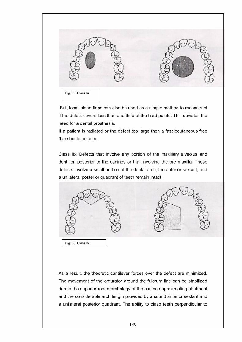
139
But, local island flaps can also be used as a simple method to reconstruct
if the defect covers less than one third of the hard palate. This obviates the
need for a dental prosthesis.
If a patient is radiated or the defect too large then a fasciocutaneous free
flap should be used.
Class Ib: Defects that involve any portion of the maxillary alveolus and
dentition posterior to the canines or that involving the pre maxilla. These
defects involve a small portion of the dental arch; the anterior sextant, and
a unilateral posterior quadrant of teeth remain intact.
As a result, the theoretic cantilever forces over the defect are minimized.
The movement of the obturator around the fulcrum line can be stabilized
due to the superior root morphology of the canine approximating abutment
and the considerable arch length provided by a sound anterior sextant and
a unilateral posterior quadrant. The ability to clasp teeth perpendicular to
Fig. 35: Class Ia
Fig. 36: Class Ib

140
the fulcrum line of the framework and the support afforded by the
remaining palate further stabilizes the prosthesis and improves the
prosthetic prognosis.
If surgical reconstruction is planned, a soft tissue flap is indicated
without osseous reconstruction because the remaining dentition and palate
are able to support the occlusal contacts over the reconstruction with a
removable partial denture. With a removable partial denture, the support is
derived from the remaining dentition and palate and not the flap. A radial
forearm fasciocutaneous free flap works well for closure of the oral cavity
because of ample soft tissue of the donor site and low donor site morbidity
relative to those of the other sites.
In an edentulous patient, the bone of the remaining maxillary
alveolus has to be sufficient to accommodate osseointegrated implants.
Forgoing osseointegration of implants in the remaining natural maxilla and
surgical closure of the defect with a fasciocutaneous free flap can result in
a difficult or impossible situation for prosthetic rehabilitation. This is due to
the inability to extend the obturator bulb into the defect and engage
anatomic undercuts for stability and retention.
Class II: Defects that involve any portion of the tooth bearing maxillary
alveolus but includes only one canine. The anterior margin of these
defects is within the pre maxilla. Also included within this class are anterior
transverse palatectomy defects that involve less than one half of the
palatal surface. Total maxillectomy comprises the majority of defects in this
class in which an incisor serves as the terminal abutment.
Fig. 37: Class II

141
Prosthetic rehabilitation of class II defects is less predictable than class I
defects. Factors that contribute to instability are fewer teeth for clasping,
reduced arch size and form and a significantly reduced supporting palate.
Further, an obturator alone is inadequate to restore cosmesis to the
midface if the orbital floor or zygoma is resected.
Some class II defects are best restored with VBCFF’s. Vascularized bone
offers the ability to re-establish the bony dental arch for the placement of
osseointegrated implants which allows the distribution of the masticatory
forces across an intact maxillary arch and thereby reestablishes a
favourable biomechanical condition in the maxilla. Furthermore, VBCFF
permit the primary reconstruction of the orbital rim and the prominence of
the zygoma tic body with autologous tissue.
Class III: Defects that involve any portion of the tooth bearing maxillary
alveolus and include canines, total palatectomy defects and anterior
transverse palatectomy that involve more than half of the palatal surface.
These defects leave little or no residual palate or dentition for the secure
retention of an obturator, which leads to a poor prosthetic prognosis. Class
III defects are best restored with VBCFF, although the soft tissue closure
serves to effectively partition the oral cavity from the nasal cavities and
maxillary sinuses, oro-dental rehabilitation is severely compromised.
Bones containing free flaps however, serve to separate the cavities along
with providing vascularized bone capable of retaining implants. Palatal
reconstruction provides a stable base to oppose the restored mandibular
arch.
Fig. 38: Class III

142
Subclasses f and z:
Defects that involve the inferior orbital rim are categorized as subclass f,
where as defects that involve the body of zygoma are categorized as
subclass z.
.
Extensive palatomaxillary defects commonly involve a vertical
component of the maxilla. The creation of subclasses, relate to the status
of the orbital floor and the zygomatic body and are essential to provide an
accurate description of the palatomaxillary defect. The orbital floor and the
zygomatic body play both functional and cosmetic roles as the ablation of
the vertical maxilla commonly results in a significant disruption of the
midface and orbit and has profound effect on function. Enophthalmoses
and diplopia can occur if the orbital contents are not supported. In addition
these patients may suffer from a cosmetic deficit that is impossible to
restore with an obturator.
VBCFF serve best to restore bone to the load bearing palate by
restoring bone to the orbital rim and the zygomatic body. It also permits the
placement of osseointegrated implants for the retention of an orbital
prosthesis.
Fig. 39: Subclass f Subclass z

143
This algorithm is used for functional reconstruction, midface restoration
and oro-dental rehabilitation according to the palatomaxillary defect
classification.
Impression Making Procedure's:
i) Conventional Impression: By Beumer and Curtis17
The objective of the preliminary impression is to record the
remaining maxillary structures and the useful portions of the defect.
An edentulous soft metal tray is selected according to the configuration of
the remaining maxilla. The medical and anterior undercuts are blocked out
with gauze lubricated with petrolatum. Adhesive is applied to the tray and
wax. The irreversible hydrocolloid material is mixed and located in the tray
with ample care to load the material laterally so as to record the lateral
configuration of the defect and a diagnostic cast is obtained.
The undesirable undercuts recorded in the cast are blocked out
with suitable wax prior to constructing the custom tray. Relief of one
thickness of base plate wax is provided for the skin graft-mucosal junction
and the superior lateral aspect of the defect. The residual palatal
structures are relieved in the customary way and the tray fabricated with
self-cure acrylic resin.
After checking the custom tray so that it extends 2-3 cm into the
cavity and extends beyond the scar band and superior to the cut edge of
the hard and soft palate, conventional border molding be carried out it is
advisable, that border molding be completed initially on the unresected
side since this serve to stabilize and orient the tray over the defect. The
lateral, posterior and anterior aspects of the defect are recorded

144
sequentially in two sections. First the area below the skin graft mucosal
junction is molded. Next, the area above the scar band is molded. In
molding the posterolateral aspect the patient should be instructed to
perform eccentric mandibular movements to account for the movement of
the anterior border of the ramus, and the coronoid process of the
mandible.
The patient should be directed to use routine head and mandibular
movements during the border moulding. The impression of the surgical site
requires that the patient perform exaggerated head movements turning left
to right with the head level, and then again with the neck flexed and
extended. The mouth should be opened and closed, and the mandible
moved laterally.
Speech and swallowing evaluation should be done to check the
seal before making the final impression. The patient should be made to
speak m and b and if there is distinction then the seal achieved is
adequate. If they are not distinct, then there is some air leakage present.
The modeling plastic is relieved approximately 1 mm in all areas,
prior to obtaining the final impression. Several perforations are made for
escape of the impression material with at least three perforations being
made along the median palatal margins. Prepare mixes of regular and
light body rubber base impression material; spatulating the regular material
slightly in advance of the light bodied material. The light body is injected
into the defect and the regular body-containing tray is seated over it.
If the anterior margin of the soft palate exhibits considerable
elevation during speech and swallowing, the portion of the impression that
engages the soft palate both superiorly and inferiorly is cut away with a
scalpel and a functional impression is made with thermoplastic wax. If the
patient exhibits extreme trismus, surgical obturator can be used for making
final impression with tissue treatment material.
For dentulous patients a preliminary impression is made in a stock
tray with irreversible hydrocolloid in a suitably modified stock tray. The tray
extensions can be extended in the defect area by using modeling
compound. Same precautions are taken as in an edentulous patient. The
design of the prosthesis is decided, necessary mouth preparation done
and the final impression of the non-defect side is made for framework
fabrication. This impression should include sufficient amount of the defect
region so as to allow the extension of the framework into the defect without

145
interference from remaining anatomic structures. The final impression of
the defect area is made only after the framework has been fabricated and
physiologically adjusted in the mouth. Autopolymerizing resin is added to
the retentive meshwork to serve as an impression tray for the obturator
portion extending into the defect. A wax occlusal rim may also be added to
assist in evaluation of facial support, tooth position and occlusal
registration. It is difficult to make the impression as the incremental
addition of impression or reline material increases the weight and causes
incomplete seating or rotation of the prosthesis away from its original
position. Adding an occlusal stop onto the occlusal rim, before the
impression is made can prevent this. With each increment added the
patient is instructed to bring the teeth together in maximum intercuspation,
thereby reseating the framework in its intended position. After border
moulding is done in the similar way as for edentulous patients, final
impression can be made in light body silicone material and can be further
refined by impression wax as discussed earlier.
ii) A foam impression technique for maxillary defects- by J. Schmaman and
L. Carr (1992). 121
TECHNIQUE:
An intraoral impression of the maxilla and entry into the defect is taken
in the conventional manner with alginate following which a special tray is
fabricated on the cast. A mushroom shaped acrylic resin retention-
relocating button is added to the special tray. A 20 ml, disposable plastic
syringe is modified to receive a latex-feeding nipple. The tip of the nipple
is cut to widen the aperture to about 5 mm. The nasopharynx and orifices
are blocked with gauze.
After adhesive is applied silicone rubber impression material is
loaded on to the tray while the button is excluded. An impression of the
residual structures, including the perimeter of the defect is taken in the
normal manner. The impression is withdrawn, checked and inserted back.
The patient is instructed to breathe through the mouth. The desired
volume of silastic foam liquid is poured in the syringe & the catalyst added
and rapidly mixed with a thin spatula.
The plunger is replaced and nipple inserted into the nostril that is
continuous with the defect. The foam is rapidly injected through the nostril
into the nasal cavity, and the syringe is removed. The defect and nasal

146
cavity are filled with foam, which expands to 4 times its original volume and
then extrudes from the nostril. After setting, this excess is removed with
scissors.
The tray with rubber impression is removed from the mouth, and
the button is withdrawn from the extremely elastic foam. The foam
impression is removed by inserting a finger into the nostril and pushing the
foam downwards and simultaneously, pulling the foam from inside the oral
cavity, as it disengages from the undercuts.
The foam impression of the defect is relocated onto the button and
is luted with sticky wax. To fabricate the cast, the foam is initially painted
with a thin coat of stone. When this sets, the cast is poured in
conventional manner. The advantage of this technique is that the
impression can be easily removed from the severe undercuts and that it is
easier when trismus is present. This disadvantage is that the rapid
reaction of the foam liquid to the catalyst limits the time.
Fig. 40: The defect. Fig. 41: Special tray and silicone impression in position.
Fig. 42: Injecting foam with modified syringe and nipple.
Fig. 43: Withdrawing the impression.
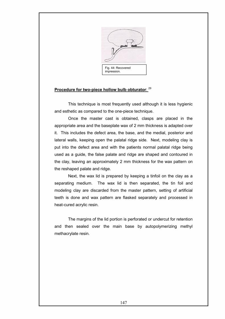
147
Procedure for two-piece hollow bulb obturator: 29
This technique is most frequently used although it is less hygienic
and esthetic as compared to the one-piece technique.
Once the master cast is obtained, clasps are placed in the
appropriate area and the baseplate wax of 2 mm thickness is adapted over
it. This includes the defect area, the base, and the medial, posterior and
lateral walls, keeping open the palatal ridge side. Next, modeling clay is
put into the defect area and with the patients normal palatal ridge being
used as a guide, the false palate and ridge are shaped and contoured in
the clay, leaving an approximately 2 mm thickness for the wax pattern on
the reshaped palate and ridge.
Next, the wax lid is prepared by keeping a tinfoil on the clay as a
separating medium. The wax lid is then separated, the tin foil and
modeling clay are discarded from the master pattern, setting of artificial
teeth is done and wax pattern are flasked separately and processed in
heat-cured acrylic resin.
The margins of the lid portion is perforated or undercut for retention
and then sealed over the main base by autopolymerizing methyl
methacrylate resin.
Fig. 44: Recovered impression.

148
Fig. 45: A. palatal view of waxed up obturator. B. waxed up obturator with the modeling clay in the defect area. C. tin foil applied over the modeling clay. D. false palate-ridge is separated. E. false palate perforated and seated over processed base. F. palatal view of the finished temporary obturator. G. tissue side view of the hollow bulb temporary obturator. H. temporary obturator inserted in the mouth.

149
Obturator bulb fabrication for edentulous patient: - by Chalian29
After the final impression is obtained, a cast is poured and
undesirable undercuts are blocked.
A stabilized base plate is made and flowed in the defect area, at
this stage; a wax lid is fitted over the defect area to leave it hollowed and to
provide the effect of a complete palate.
Then occlusal wax rim is adapted to prepare the cast for centric
and vertical records. With resulting records the casts are mounted on the
semi adjustable articulator. The teeth are selected, and arranged into the
rims. Then the wax try in is done. Finally the case is ready for laboratory
processing.
The palatal defect is filled in with modeling clay and given a palatal
shape. A false lid is made from autopolymerizing acrylic resin. This is set
aside while the case is flasked and processed.
The lid is then added to the master base to close the palatal portion
of the hollow bulb, and is sealed with quick-curing acrylic resin. Usual
finishing and polishing of the denture follow this.
Procedure for One Piece Hollow Obturator – Chalian
After the wax try in of the trial denture, the denture is festooned and
finally waxed as any conventional denture. The denture is flasked and
boiled out in the usual manner. When the case is completely flushed with
boiling water and thoroughly dried, a shim is constructed. The undercut
areas in the defect are blocked out and the entire defect area is relieved
with one thickness of baseplate wax. Three stops deep enough to reach
the underlying stone of the master cast are placed in the wax to facilitate
proper positioning of the shim. One thickness of base plate wax is also
placed in the top half of the flask over the teeth and the palate area to form
the top wall of the shim. This also allows for the thickness of heat cure
acrylic on the palatal side of the denture. Autopolymerizing resin is mixed
and rolled to about 2 mm in thickness after reaching the dough like stage.
A layer of resin is then contoured over the wax relief in the defect side, with
another layer on the wax in the top half of the flask. The flask is then
closed and allowed to set for a minimum of 15 minutes.
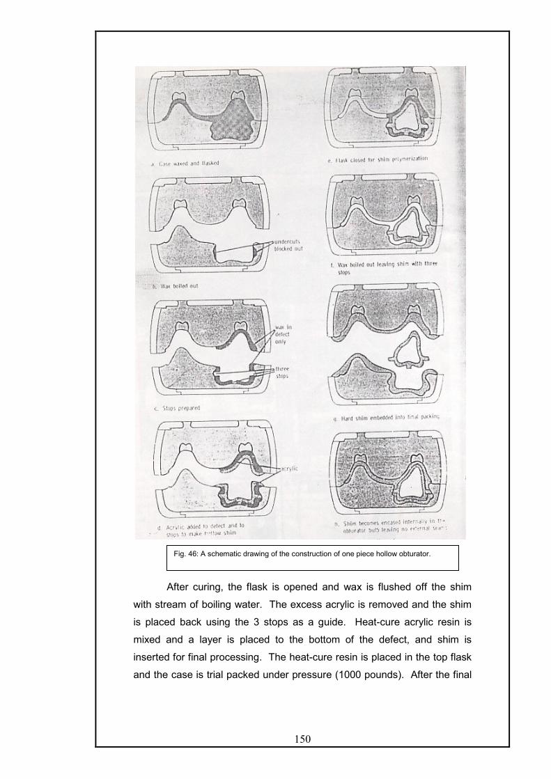
150
After curing, the flask is opened and wax is flushed off the shim
with stream of boiling water. The excess acrylic is removed and the shim
is placed back using the 3 stops as a guide. Heat-cure acrylic resin is
mixed and a layer is placed to the bottom of the defect, and shim is
inserted for final processing. The heat-cure resin is placed in the top flask
and the case is trial packed under pressure (1000 pounds). After the final
Fig. 46: A schematic drawing of the construction of one piece hollow obturator.

151
closure, the case is cured, deflasked, finished and polished in the
customary manner.
This technique has the following advantages:
i. There are no lines of demarcation on the denture to discolor.
ii. The undercut areas of the defect are thick enough to allow for
adjustment if necessary.
iii. It is simple and consumes very little more laboratory time than a
conventional denture.
iv. Accuracy is assured.
Other Important Methods Of Fabricating Hollow-Bulb Obturators:
I) THE SILICONE RUBBER OBTURATOR - Described by Rahn and
Boucher.112 Before the advent of resilient denture materials hollow bulb
obturators were used as a means of gaining additional retention and also
as a means of carrying supplemental forms of radioactive materials for
treatment of recurrent tumors. But, sometimes not all the available
undercut areas in the defect could be utilized and retention was not always
satisfactory.
Most of the disadvantages can be overcome by fabricating the
base portion of such prosthesis with one of the heat vulcanized medical
grade silicone rubber materials. Their excellent dimensional stability and
resilient character, aid in providing satisfactory retention, by permitting
closer engagement of the undercuts areas, thus providing a seal for the
palatal openings. These materials also ensure accurate delivery of
brachytherapy tubes, which are to be placed, in closure and intimate
relationship to the tumor site, unlike acrylic resin bulb, which cannot by
pass the undercut areas easily.
Method of fabrication:
After duplicating the master cast. The crown portions of the remaining
teeth are cut from the cast down to the gingival crevice. The wax pattern is
formed to the design desired to be reproduced in the silicone rubber
material.
152
When using silicone rubber, a flask should be used which can be
bolted together. After flasking and boiling out the wax pattern, all the stone
surfaces are treated with silicone rubber mold release material.
There are two types of silicone rubber sheet material, depending upon
specific needs. The material is available in varied durometer hardness,
and may be used together when a different degree of firmness is needed
in a specific area or a reinforcement is supplied by an inlay of a silicone
rubber impregnated Dacron.
The mold is packed in a similar fashion, as is acrylic resin.
Polyethylene separating sheets are used during the trial packing phase to
ensure separation and withdrawal of the flask halves. The flask halves are
pressed together in a bench press slowly so that putty-like material has an
opportunity to flow. The excess flash is cut away with a sharp instrument
and necessary reinforcement if necessary, in areas like labial frenum, the
portion distal to last tooth or any thick isthmus is done before the final
closure.
After final closure, the flask halves are bolted together and the entire
assembly is placed in the processing oven, which should be a dry heat,
natural air circulating type oven, with an accurate temperature control
system. The air circulation provides for the escape of by products of
vulcanization. The flask is left in the oven for one hour at 300oF. After
removing, it is then allowed to bench cool, and is finally separated. The
molded form may be trimmed off any excess flash at this time, but it must
be returned to the over for a period of 4 hours at a temperature of 400oF in
order to complete the curing process. It is during this later period of time,
that the by-products of vulcanization the driven out from the rubber mold.
Upon removal, from the oven, the rubber base is finished neatly
and placed on the master cast and super structure of the denture is
constructed in a conventional manner. The depth of the defect is filled with
wax or plaster, so that base plate material could be adapted over it, by-
passing the depression. Occlusal rims are constructed and the baseplate
and rubber base are united together by application of pressure sensitive
silicone adhesive. This procedure facilitates accurate intraoral recording of
centric relation and vertical dimension. After mounting on the articulator,
the occlusion unit areas is set and wax-try in is accomplished.
If a wax plug is used to bypass the depression, it is adjusted at this
time to form a collar, which fits into a portion of the concavity. This

153
provides additional support for the hollow bulb against lateral stress and
also allows for greater surface contact for the bonding agent.
The wax pattern superstructure is then removed, flasked separately and
upon recovery, finished and polished.
The base-contacting surface of the acrylic resin is ground,
roughened and lined with a silicon primer. The rubber base is cleansed
with ether or chloroform. Care is taken to see that both surfaces are not
contaminated in any way by fingers or anything else.
The permanent bonding material between resin and rubber base is
another form of silicone rubber, which cures at room temperature.
To ensure proper alignment, the lower complement of the articulator is
used, making certain that incisal pin contacts the guide table and vertical
dimension and centric relations are maintained. Upon closure of the
articulator, the excess adhesive material will be pressed and will fill the
space created therein. The excess is carefully removed. The articulator is
held together with rubber bands to ensure that the two components do not
shift their relationship. A minimum of 12 hours is required for the adhesive
to set. After this, the components may be further finished with moist free
pumice.
II) INFLATABLE OBTURATOR PROSTHESIS- described by A.G.L.Payne
W.G.Welton (1965) 105
It consists of a latex rubber balloon attached to a denture by means of a
silicone rubber former, into which is incorporated an air valve. The balloon
is inflated with air to fill the surgical defect.
PROCEDURE
Preparation of the denture; The upper denture is constructed in the usual
way and finished with the solid acrylic resin obturator extending only about
3mm into the defect. By working form the fitting surface, the obturator is
hollowed out as far as possible and a hole 1cm in diameter is cut through
the labial flange over the lateral incisor tooth. This aperture will give
access to the air-retaining valve. A groove 2mm deep is cut out into the
inner aspect of the periphery of the hollowed out portion, about 2mm below
its edge.

154
The valve mechanism:
The most suitable air-retaining valve is an automobile valve. In the
completed assembly, the valve is subjected to torque when the inflator is
connected. It is necessary, therefore to attach tags to the valve sleeve to
prevent its displacement. As the valve is to be embedded freehand in
silicone rubber, it is essential to decide the ideal position in order that no
portion of the valve or its tagging will be exposed. The air exit aperture
must be sealed with wax, and a wax column is extended vertically to give
an indication of the position of the valve after the embedding is complete.
With the valve supported from the front, silicone rubber is spatulated into
the hollowed obturator so as to embed the valve completely. Care must be
taken to fill the grooves previously made. When the silicone rubber has
cured, it is smoothed and trimmed to the shape of the obturator base and
the wax column is removed down to the valve exit.
The inflator: The cap for the valve is reduced in length, and a hole 1mm in
diameter is drilled through the center of the cap and its rubber washer.
The washer is removed and a tube 5mm in diameter, about 1.5 cm long is
soldered onto the valve cap. After the washer is replaced 2.5 cm of well
roughened metal tube, 1.0 mm in diameter is passed through the valve cap
until about 2mm of the tube is left extending above the washer. This tube
is held in its central position inside the larger bore tube by self-curing
acrylic resin. The projecting tube in the valve cap is reduced carefully till it
just depresses the valve core when valve cap is screwed tight on the
valve. Thus an easy passage of air, and restoration of seal immediately
when the inflator is removed is assured. The modified cap is connected by
means of a short length of rubber tubing to an air bulb having a simple
one-way valve.
Fig. 47: Denture made with solid acrylic obturator that extends 3mm into the surgical opening.

155
ASSEMBLY AND USE OF THE OBTURATOR
A latex balloon is stretched over the silicone rubber former that contains
the valve. The former is then pressed into the hollowed out obturator. The
silicone rubber former is retained by the engagement of the silicone rubber
into the groove initially made. Inflation of the balloon causes it to stretch
and automatically seal itself to the acrylic resin of the obturator in the
denture. The size of inflation can be adjusted and experience soon
dictates the most advantageous size for each patient. The valve aperture
on the labial surface is sealed with a small silicone plug.
This appliance has following advantages.
- It provides a perfect oronasal seal and is self adjusting to changes
in the shape of tissue after surgery
- The balloon may be inflated after insertion and therefore, this
appliance may be used in cases with severely limited opening.
Fig. 48: Obturator hollowed out to receive the silicone rubber former that will carry the air valve. The groove just below the top edge serves to lock the silicone former in place. The hole in the labial surface will accommodate the inflator.
Fig. 49: Valve shown in position with a wax column (C) that will maintain an airway from the obturator into a balloon while a silicone rubber former is made to fill the hollow obturator. Metal tabs are soldered to the valve housing to prevent its rotation in the silicone rubber former.
Fig. 50: the denture with the silicone rubber former. Note the groove on top that will lock it in position, while the hole in the top of the former that was maintained by the wax column.
Fig. 51: the inflator is connected to the valve cap through the aperture in the labial surface. The latex balloon is in position and inflated. The opening into the valve through the labial surface is closed with a silicone plug.

156
- It is light in weight and its simple construction permits easy
cleansing and maintenance.
III ) EMERGENCY TEMPORARY OBTURATOR
- OSCAR E. BEDER (1968) 11
A temporary emergency type of obturator made for patients with acquired
palatal, defect these obturators can be made in single patient visit, if
necessary, since the speed of construction may be essential for some
patients.
PROCEDURE
i) Make a master cast from an impression of the maxillary arch.
ii) Contour strategically placed wire clasp on the teeth of the cast.
iii) Upon this cast adapt a softened sheet of easily manipulated wax,
trim it to the correct border outline, and add wax for contour and
thickness as indicated.
iv) Cut index grooves in the master cast. Coat all exposed plaster with
a separating medium and pour a plaster core over the wax,
extending it to the master cast.
v) Immerse the cast and core in hot water until the wax is soft.
Separate the core from the cast and peel out the wax.
vi) Cut a funnel shaped hole through the plaster core and extend it to
the obturator region. Cut an air vent hole approximately 1/8” in
diameter through the core over the intact vestibular area. Clean all
plaster surfaces and coat them with a tinfoil substitute.
vii) Pour a small amount of monomer in the mold and empty it out
quickly. Pour some fluid cold cure acrylic resin into the obturator
part of the cast. Reassemble the parts and pour an adequate
Fig. 52: Assembled cast and core to illustrate the funnel shaped hole and vent.

157
amount of the acrylic resin into the funnel-shaped hole in a thin
stream until it flows out of the air vent.
viii) Place the entire complex into a pressure pot and raise the air
pressure to 25 pounds.
ix) After curing, carefully remove the plaster and recover the
prosthesis.
x) Trim excess acrylic resin, and polish before delivery.
IV) FABRICATING A HOLLOW OBTURATOR USING TWO FLASKS
WITH INTERCHANGEABLE PARTS.
This technique has been described by A.S. El Mahdy'(1969). 45
PROCEDURE:
Flasking the appliance: Two identical flasks are required [flask U-L and F1
- F2]. Their upper and lower halves should be interchangeable and they
should fit accurately. The trial prosthesis is invested in flask U-L in the
usual manner of investing an upper trial denture.
Elimination of wax: Flask U-L is immersed in hot water, opened, and the
wax is eliminated.
Waxing the impression surfaces of the prosthesis in the lower half of the
flask [L]: An appropriate thickness of baseplate wax is added to establish
the desired thickness of acrylic resin in part A of the obturator. This
amount of wax should eliminate all undercuts if present. Add a thin layer
of wax to part B. Cover the wax with a wet sheet of cellophane and make
a trial closure of the two halves of flask U-L. There should be metal-to-
metal contact.
Waxing the polished surfaces of the obturator in the upper half of the flask
[U]: Add baseplate wax to establish the desired thickness of acrylic resin
on the polished surfaces of the obturator part. This wax should contact the
wax on the impression surface and make a seal at S. Again cover the wax
Fig. 53: A cross section of flask U-L shown after elimination of wax. U – upper half, L –lower half, A- obturator part, B – conventional part of the prosthesis.
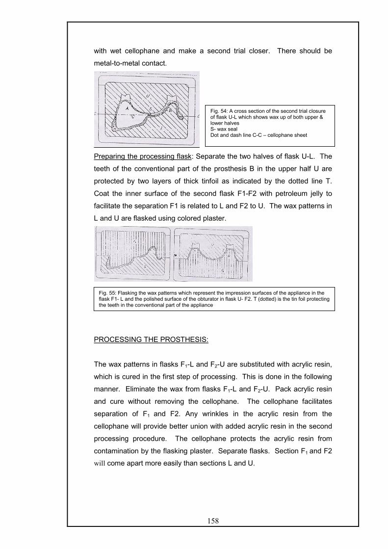
158
with wet cellophane and make a second trial closer. There should be
metal-to-metal contact.
Preparing the processing flask: Separate the two halves of flask U-L. The
teeth of the conventional part of the prosthesis B in the upper half U are
protected by two layers of thick tinfoil as indicated by the dotted line T.
Coat the inner surface of the second flask F1-F2 with petroleum jelly to
facilitate the separation F1 is related to L and F2 to U. The wax patterns in
L and U are flasked using colored plaster.
PROCESSING THE PROSTHESIS:
The wax patterns in flasks F1-L and F2-U are substituted with acrylic resin,
which is cured in the first step of processing. This is done in the following
manner. Eliminate the wax from flasks F1-L and F2-U. Pack acrylic resin
and cure without removing the cellophane. The cellophane facilitates
separation of F1 and F2. Any wrinkles in the acrylic resin from the
cellophane will provide better union with added acrylic resin in the second
processing procedure. The cellophane protects the acrylic resin from
contamination by the flasking plaster. Separate flasks. Section F1 and F2
will come apart more easily than sections L and U.
Fig. 54: A cross section of the second trial closure of flask U-L which shows wax up of both upper & lower halves S- wax seal Dot and dash line C-C – cellophane sheet
Fig. 55: Flasking the wax patterns which represent the impression surfaces of the appliance in the flask F1- L and the polished surface of the obturator in flask U- F2. T (dotted) is the tin foil protecting the teeth in the conventional part of the appliance

159
Remove the colored investing plaster, which identifies F1 and F2, and also
remove the cellophane from the cured acrylic resin. Remove the tinfoil (T),
which was used to protect the teeth on the conventional part of the
prosthesis. Do not disturb the contents of sections L and U. Make a trial
closure of sections U and L and make sure metal-to-metal contact is
achieved. Any acrylic resin in the seal area must be reduced to proper
thickness. Clean the acrylic resin surfaces and prepare for the addition of
a new mix of acrylic. Any excess thickness can be reduced at this stage to
further reduce the bulk and weight.
SECOND PROCESSING
Join the two halves of flask U-L. This unites the two previously processed
segments and will cure the remainder of the conventional part of the
prosthesis. Make a new mix of acrylic resin and place it along the edges of
the two parts and in area T. Make trial closure to ensure sufficient acrylic
resin. Remove the cellophane and process. Remount and finish in the
conventional manner.
Advantages of this method are: -
- Control of thickness and weight are achieved.
- Accuracy is assured because the relationship of various
components is maintained.
- The method is easy to learn and teach.
- It can be used in conjunction with a metal framework.
V) A SIMPLIFIED TECHNIQUE FOR FABRICATING A LIGHTWEIGHT
OBTURATOR. This technique was described by Yoshinobu Tanaka, Henry
O Gold and Samuel Pruzansky (1977). 17
Fig. 56: A cross section of the reassembled flask U-L, which contains the completed appliance with the hollow bulb obturator.
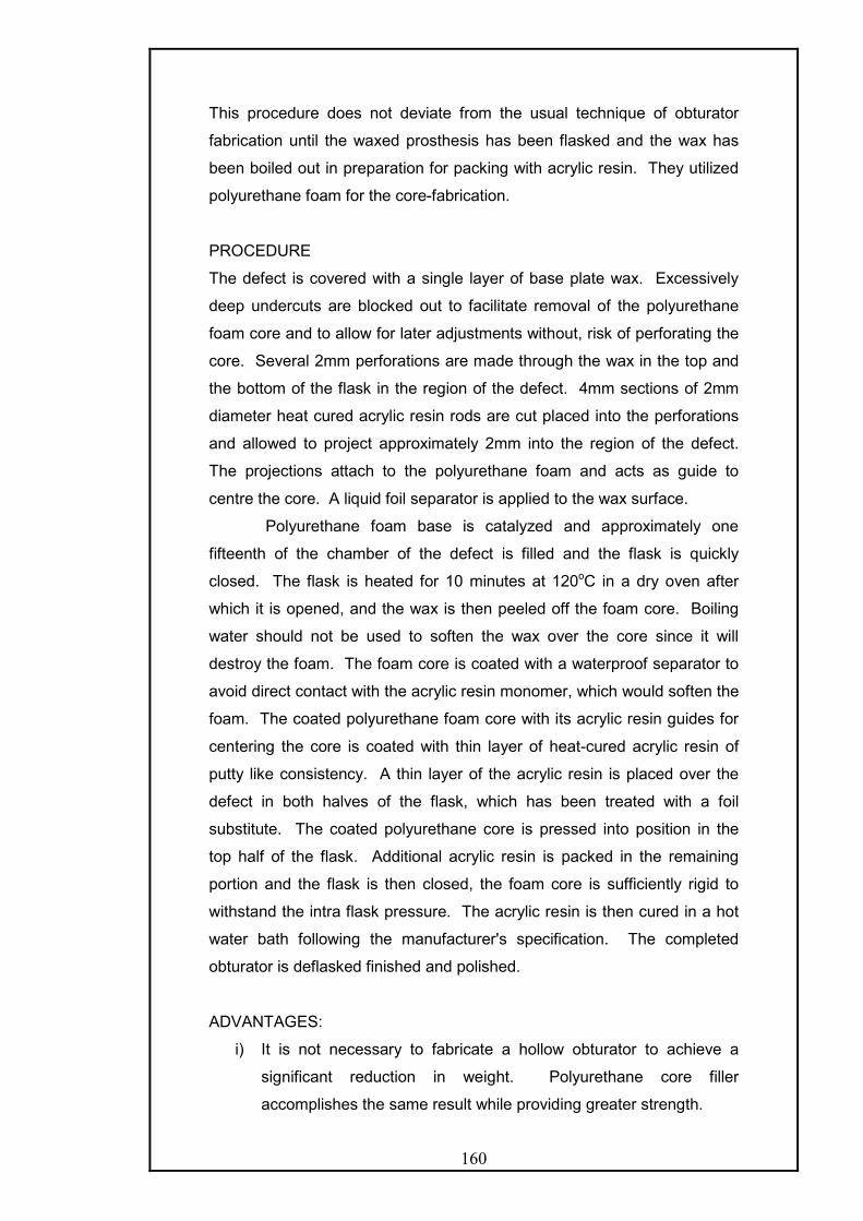
160
This procedure does not deviate from the usual technique of obturator
fabrication until the waxed prosthesis has been flasked and the wax has
been boiled out in preparation for packing with acrylic resin. They utilized
polyurethane foam for the core-fabrication.
PROCEDURE
The defect is covered with a single layer of base plate wax. Excessively
deep undercuts are blocked out to facilitate removal of the polyurethane
foam core and to allow for later adjustments without, risk of perforating the
core. Several 2mm perforations are made through the wax in the top and
the bottom of the flask in the region of the defect. 4mm sections of 2mm
diameter heat cured acrylic resin rods are cut placed into the perforations
and allowed to project approximately 2mm into the region of the defect.
The projections attach to the polyurethane foam and acts as guide to
centre the core. A liquid foil separator is applied to the wax surface.
Polyurethane foam base is catalyzed and approximately one
fifteenth of the chamber of the defect is filled and the flask is quickly
closed. The flask is heated for 10 minutes at 120oC in a dry oven after
which it is opened, and the wax is then peeled off the foam core. Boiling
water should not be used to soften the wax over the core since it will
destroy the foam. The foam core is coated with a waterproof separator to
avoid direct contact with the acrylic resin monomer, which would soften the
foam. The coated polyurethane foam core with its acrylic resin guides for
centering the core is coated with thin layer of heat-cured acrylic resin of
putty like consistency. A thin layer of the acrylic resin is placed over the
defect in both halves of the flask, which has been treated with a foil
substitute. The coated polyurethane core is pressed into position in the
top half of the flask. Additional acrylic resin is packed in the remaining
portion and the flask is then closed, the foam core is sufficiently rigid to
withstand the intra flask pressure. The acrylic resin is then cured in a hot
water bath following the manufacturer's specification. The completed
obturator is deflasked finished and polished.
ADVANTAGES:
i) It is not necessary to fabricate a hollow obturator to achieve a
significant reduction in weight. Polyurethane core filler
accomplishes the same result while providing greater strength.
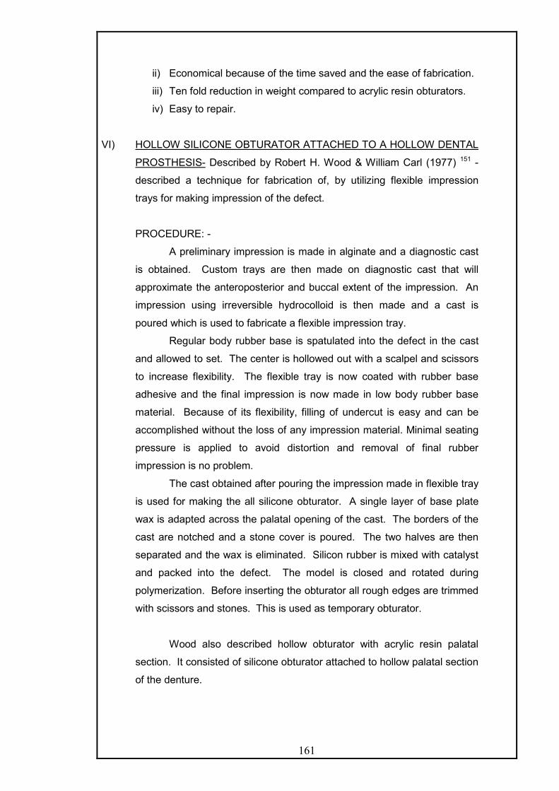
161
ii) Economical because of the time saved and the ease of fabrication.
iii) Ten fold reduction in weight compared to acrylic resin obturators.
iv) Easy to repair.
VI) HOLLOW SILICONE OBTURATOR ATTACHED TO A HOLLOW DENTAL
PROSTHESIS- Described by Robert H. Wood & William Carl (1977) 151 -
described a technique for fabrication of, by utilizing flexible impression
trays for making impression of the defect.
PROCEDURE: -
A preliminary impression is made in alginate and a diagnostic cast
is obtained. Custom trays are then made on diagnostic cast that will
approximate the anteroposterior and buccal extent of the impression. An
impression using irreversible hydrocolloid is then made and a cast is
poured which is used to fabricate a flexible impression tray.
Regular body rubber base is spatulated into the defect in the cast
and allowed to set. The center is hollowed out with a scalpel and scissors
to increase flexibility. The flexible tray is now coated with rubber base
adhesive and the final impression is now made in low body rubber base
material. Because of its flexibility, filling of undercut is easy and can be
accomplished without the loss of any impression material. Minimal seating
pressure is applied to avoid distortion and removal of final rubber
impression is no problem.
The cast obtained after pouring the impression made in flexible tray
is used for making the all silicone obturator. A single layer of base plate
wax is adapted across the palatal opening of the cast. The borders of the
cast are notched and a stone cover is poured. The two halves are then
separated and the wax is eliminated. Silicon rubber is mixed with catalyst
and packed into the defect. The model is closed and rotated during
polymerization. Before inserting the obturator all rough edges are trimmed
with scissors and stones. This is used as temporary obturator.
Wood also described hollow obturator with acrylic resin palatal
section. It consisted of silicone obturator attached to hollow palatal section
of the denture.

162
Fabrication of silicone obturator: -
It is made in accordance with the technique described by Hahn54.
A double thickness of baseplate wax is adapted into the defect surface
within the cast without leaving internal undercuts and extended to the
palatal borers. A thin ring of wax serving as a retentive lip is added to the
inside just superior to the palatal border. Another keyed stone cover
extending into the wax up is poured for the master cast.
Silicone rubber is mixed and placed in the cast and the cover is
then seated and clamped or held with rubber bands until the silicon has
cured. The resulting obturator is next reseated in the master cast and a
plaster core is poured up to the retentive lip. Self-curing acrylic resin is
sprinkled, poured or moulded over the palatal surface in a thin layer. The
acrylic resin must be adapted under the retentive lip inside the obturator.
The obturator section will be retained against the acrylic resin section in
the undercut.
Fabrication of hollow palatal section: -
The dental section of the prosthesis is an extension of the acrylic
resin palatal section. Wax occlusal rims are added to the acrylic resin
section. A rim of maxillary teeth may be pre-assembled in the laboratory in
occlusion with a cast of the mandibular teeth. The obturator with a
softened wax rim is inserted into the mouth and the assembled tooth rim is
placed against the mandibular teeth and held while the patient closes
gently into the wax. A vertical dimension of occlusion is determined by
phonetics and esthetics. The wax trial prosthesis is completed with the
palatal section hollowed out as much as possible to reduce weight. A
ledge is carved in the palatal wax just lingual to the teeth.
After processing of the denture one to one and a half thickness of
base plate wax are adapted to the palatal ledge to provide normal palatal
contour. The sheet of wax is processed and attached to the denture.

163
Disadvantages of this method are: -
i) It is large and heavy, making it difficult to insert.
ii) Retention will be marginal at the best.
iii) Vertical displacement occurs because of absence of superior stops.
iv) Esthetically less pleasing.
v) Discomfort from mucosal contact.
VII) TECHNIQUE UTILIZING DOUBLE INVESTMENT PROCEDURE
PROCESSING AGAINST ICE: This procedure has been described by
Aaron Schneider (1978) 122
PROCEDURE:
Make a master cast in the usual manner and outline the borders.
With plaster, block out undercuts created by surgery. Wax up of the base
is done making sure to wax the internal part of the cavity as thin as
possible. Invest the cast with defect in the lower half of the flask. Paint the
plaster investment and the wax up with petroleum jelly and plaster of paris
is poured in the upper half of the flask. After setting of plaster, separate
the flask and set the second part aside, followed by covering the open part
of the cavity and wax to complete a full palate. Pour the third part of the
flask and separate when it hardness. Wash out all the wax, with boiling
water and thoroughly clean the plaster and paint with a separating
medium. Mix acrylic resin; pack the cavity in the first invested flask. Trial-
pack several times and remove all excess acrylic. Process in the usual
manner. The next step can be performed in one of the following two ways.
Fill the cavity with water and place in a freezer overnight or fill the cavity
with crushed ice. Make another mix of acrylic resin and when dough stage
is achieved pack it over the ice-filled cavity and process the resin.
Remove the processed obturator from the flask, trim and polish it. Create
a hole to remove water, which is later resealed with cold cure acrylic resin.
Complete the denture, by making the jaw relation records and arrange
teeth directly on the finished bases.

164
VIII) COMPLETELY HEAT CURED ACRYLIC RESIN HOLLOW
OBTURATOR USING A FILLER MATERIAL THAT IS ABSENT FROM
THE FINAL PROSTHESIS. – Described by Worley et al (1983) 152
PROCEDURE:
It consists of conventional technique of teeth arrangement,
festooning, flasking and wax elimination. The defect side is covered with
baseplate wax on both sides of the flask. Damp asbestos strips mass is
wrapped in a sheet of wet cellophane and placed into the waxed defect
area and the flask is closed. The asbestos will conform to the shape of the
waxed defect. The final form of the asbestos is preserved and the wax
eliminated. A split pack technique is used for packing. The acrylic resin
covering the defect should be as nearly as possible the same thickness as
the wax blockouts and there should be no undercuts of acrylic resin
existing on either side of the flask.
Before packing the acrylic resin, tinfoil substitute is applied and
allowed to dry. Acrylic resin is then packed and asbestos form with
cellophane around it is gently placed into the defect area. Trial pack two or
three times, with the asbestos form remaining each time to control the
thickness of the acrylic resin on the walls of the defect. Before final
closure, remove the cellophane from the asbestos form and replace the
cellophane with a sheet of elastophane. Two sheets of elastophane
between the flasks are placed to keep the two acrylic resin sections from
curing together. The flask is final closed and the resin cured.
After curing elastophane and asbestos are removed and a new mix
of acrylic resins applied at the junctions of obturator section and the
denture base and closed again for curing. The method besides being
accurate also controls the thickness of hollow obturator prosthesis.
IX) TECHNIQUE FOR THE FABRICATION OF CLOSED HOLLOW
OBTURATOR PROSTHESIS- by Minsley et al (1986).
This technique allows for control of wall thickness of the obturator
extension thereby minimizing the weight of the prosthesis. In addition, the
junction between the lid and the palatal portion is remotely located in
relation to the lid thus minimizing micro leakage.
TECHNIQUE: -

165
After blocking out the undercuts in the defect, the cast along the defect is
covered with two sheets of pink baseplate wax, which is processed in a
conventional manner to obtain the acrylic base with obturator extension. A
recess is cut around the palatal opening of the obturator extension to a
depth of 1.5 mm. The interior of the hollow extension is filled with damp
pumice to within 1-1.5 mm of the edge of the recess.
An irreversible hydrocolloid impression of the entire palatal portion
of the obturator excluding, the joining is made and is reinforced with plaster
backing. The cast so obtained from above impression is then used for
making autopolymerizing acrylic resin lid, which is then checked over the
palatal opening of the obturator for fit and is fixed to the obturator opening
with acrylic resin.
A second ledge is then cut parallel to the flange of the obturator
and across the posterior palatal seal. This ledge should be 4-5 mm below
the top of the flange, 1 mm in depth ending in a but joint. Wax rims are
then attached to the base of the prosthesis, maxillomandibular records,
teeth arrangement is then carried out by conventional procedures.
X) LIGHT CURED HOLLOW OBTURATOR: It was described by I.C.
Benington (1989)14
TECHNIQUE:
i) Duplicate the obturator prosthesis.
ii) Add impression compound to the immediate prosthesis to indicate the
extent of the desired obturator.
iii) In regular viscosity polysulfide rubber, record a final impression of the
defect at the trial stage to procure the best fit possible for the new hollow
obturator.
iv) Pour a stone model and when hard, sandwich the mold between a
plaster base and lid. The artificial teeth are invested in the superior plaster
layer.
v) Boil out the wax and remove the impression material.
vi) Where the cavity undercuts are deep, section the master cast to
facilitate accurate adaptation of the resin to the cast walls and for ease of
removing the obturator after curing.
vii) Coat the stone cast with sodium alginate separating medium and allow
drying.

166
viii) Carefully adapt sheets of light-cure resin to cover the walls of the
defect. When the individual cast sections are assembled on the plaster
base, the obturator is complete except for the junctions.
ix) Apply prescribed bonding agent to the margins of each section and
firmly adapt thin cords of resin along each junction. Verify a complete seal
and uniform thickness of resins on the walls.
x) Using a light-cure source, cure for 4-5 minutes. Then pack resin into
the plaster lid to engage the teeth. Fit the lit on the mold and observe that
the resign margins in the plaster lid are adapted to the cured hollow
obturator section and cure.
xi) Remove the cured base from the mold and seal it on obturator section.
xii) Unite the base and obturator section by adapting a thin cord of resin
around the junction and cure.
xiii) Trim and polish the completed obturator before insertion.
Advantages:
i. The ease and rapidity of the technique expedites rehabilitation by
introducing the hollowing obturator at the earliest opportunity.
ii. The technique is versatile because the base and teeth may be cured in
conventional poly (methyl methacrylate) and bonded to the light cured
obturator when necessary.
iii. Easy to repair by using increments of visible light- cured resin
iv. Impermeable to oral fluids.
v. A light accurately fitting obturator aids in the retention of the prosthesis
and resonance of the voice.
XI) AN INNOVATIVE INVESTMENT METHOD FOR FABRICATION OF A
CLOSED HOLLOW OBTURATOR PROSTHESIS: - This technique is
described by Karen Mc Andrew, Sandra Rothenbeger et al (1998) 86
PROCEDURE:
Create the master cast design and fabricate the metal framework. Verify
the fit of the metal framework clinically. Make a functional impression of the
defect area and fabricate an altered cast. Fabricate a wax or
autopolymerized acrylic resin record base and wax occlusion rim. Record
the maxillomandibular relations. Set the teeth in wax and verify clinically
with wax try in finish the waxing and seal it to the cast for investing and
carry out dewaxing. Once the wax has been eliminated, open the flask and

167
block out the undercuts along the floor and walls of the defect area with
wax to a minimal thickness of 3 mm.
Cover the area of the palate with a 3 mm layer of wax. It is
important to cover the retentive portion of the framework so that this area
will eventually be replaced with processed acrylic resin (to minimize the
possibility of leakage along the framework resin interface.) Wax a ledge
around the periphery of the defect to leave an opening to the defect area.
Verify the fit of the portion of the flask containing teeth. Relieve any areas
of wax that prevent full seating of the flask. Place another top flask onto
the waxing of the hollow defect. Invest with plaster and boil out the wax.
Separate the flask and smooth the plaster index of the hollow section.
Pack and process the hollow section and palate with heat-polymerized
acrylic resin.
Fig. 57: Metal framework has been fabricated, verified intraorally for accurate fit and seated on master cast.
Fig. 58: Investment of completed waxing after clinical verification of esthetics and accurate registration.
Fig.59. Master cast flask after wax investment and boil out.
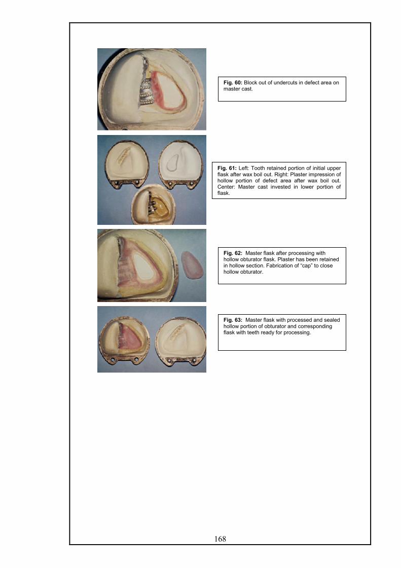
168
Fig. 60: Block out of undercuts in defect area on master cast.
Fig. 61: Left: Tooth retained portion of initial upper flask after wax boil out. Right: Plaster impression of hollow portion of defect area after wax boil out. Center: Master cast invested in lower portion of flask.
Fig. 62: Master flask after processing with hollow obturator flask. Plaster has been retained in hollow section. Fabrication of “cap” to close hollow obturator.
Fig. 63: Master flask with processed and sealed hollow portion of obturator and corresponding flask with teeth ready for processing.

169
Separate the processed flasks, with the plaster remaining in the obturator
section. Bevel the outer edges of the acrylic resin section and fabricate a
light- polymerized resin cover to fit over this area. Gently remove the
plaster from the obturator section with a bur and reduce the thickness of
resin within this section. Do not perforate the floor or walls of the section
and leave a minimal thickness of 3mm. Lute the cover to the opening with
visible light polymerizing or autopolymerizing acrylic resin.
Place the initial flask, with the invested teeth, onto the flask containing the
processed base. Relieve, any areas that prevent complete seating of the
flask. Roughen all areas of the processed base the pack heat-
polymerizing acrylic resin and process teeth onto the obturator followed by
deflasking the denture and equilibration of occlusion. Polish and deliver
the prosthesis.
Advantages:
i. This technique provides a lightweight and seamless obturator.
ii. It can be used for either complete or partially edentulous cases.
iii. It uses one master flask against two separate processing flasks.
iv. Clinical and laboratory time are minimized.
v. A durable virtually water tight prosthesis is obtained that can be used
alone or in conjunction with an extra oral prosthesis.
Fig. 64. A, Polished palatal surface of completed obturator. Coverage of “cap” junction surrounded with heat-processed acrylic resin. B, Tissue view showing extension of hollow obturatorsection.

170
OPEN OBTURATOR
This technique was described by Arie Shifman (1983) 126
TECHNIQUE
Box the final impression and pour the cast in artificial stone. Leaving the
floor of the defect uncovered, two layers of baseplate wax is added to the
vertical walls of the defect. Additional wax may be added where future
reduction of the obturator is anticipated.
Drill two holes into the base portion of the cast, where the defect is present
and cement 2 handpiece burs in it. The proximal end of burs should
protrude 2-3 cm into the defect portion. Trial pack a silicon based material
without the accelerator to determine the correct amount required to fill the
defect portion of the cast to the level of remaining palate. Mix the
predetermined amount of silicone with the accelerator according to
manufacturer instruction and pack it into the defect portion.
After the silicone has set, soften and remove the wax liner from the cast
and remove the hardened silicone from the inverted burs. The burs are
index for the detachable silicones core of the obturator. Proceed with an
accepted technique for the laboratory fabrication of an obturator. Cut the
silicone core into pieces and remove it from the finished obturator.
Advantages of this method:
i. Processing is better with improved vision and control of proper
extensions of the obturator.
ii. Deflasking is easier and the acrylic resin proceed against silicone has
a smoother surface than against gypsum material.
iii. With this method, retention and stability are not altered, as the lateral
and anterior wall heights as well as medial and posterior extensions
remain the same. The weight is also favorably reduced.
iv. This design produces improved speech, intelligibility, facilitates hygiene
and is easier to fabricate.

171
HOLLOW OBTURATOR WITH REMOVABLE LID – Phansokol & Martin
(1985) 106
It is an alternative to closed or open hollow obturators and has the benefits
of both and allows the patient to clean the inner surface. In this technique
an obturator is made with any acceptable technique with the superior
border 5 mm thick and at least 5 mm from the superoinferior border. It
must not touch soft tissue. A line is drawn on the obturator 4 mm from the
superior border, a large fissure bur or disk is used to make a ledge along
the outer border. A groove on the lower half of the ledge is made with No.
6 round bur. The edges are rounded and polished. The hollow extension is
filled with modeling clay to make flat surface. An impression of the
obturator is made in alginate, poured in stone and mouthguard material is
used by vacuforming to make the removable lid.
A lot of techniques have been presented for modifications of an existing
obturator.
Ziada & Donovan (2004) 156 described a procedure for reducing the vertical
height of the hollow box obturator in which a cap like piece of 4 mm height
from the highest point is cut, and tried in the patient to the desired height.
A lid is then fabricated with light cured denture base material.
Wang and Hirsch (1997) 144 described a procedure to convert an open
hollow obturator into a closed one.
Technique:
- The tissue side of the obturator base is first relined by
chairside reline material, which acts as an impression
material.
- The remainder of the acrylic base is lubricated with petroleum
jelly.
- The relined obturator is boxed with 2 3/4th high adhesive
paper.
- The cast is poured with a mixture of fast set stone and
plaster.

172
- The cast is separated carefully and reline material removed
and then visible light cure resin material used to close the
open end.
Implant Retained Prosthesis For Maxillary Defects.17,100,101,119,135
Cantilevering forces, which are generated by prosthesis for maxillectomy
defects, are disadvantageous gravitationally and can be progressively
destructive, even when fulcrumed with multiple rests and minimal undercut
engagement. This is particularly evident when a few sound teeth are called
upon to support a contralateral prosthetic dentition, even with a gate hinge
type of load distribution. Osseointegrated implants can play a pivotal role in
the rehabilitation process by augmenting the available retentive base or by
replacing critical missing teeth.
Implants provide retention; enhance support and stability of the prosthesis.
The anteroposterior defects as seen in congenital defects are more
amenable to implant restoration because lateral (cross arch) stability can
often be attained. Lateral defects, are more difficult restorative problems
as cross arch stability is missing and resistance to superior displacement is
missing unilaterally.
The number of implants and their location is determined by the nature of
the defect and the available bony sites. The most ideal location in the
edentulous total maxillectomy patients is the residual premaxillary segment
because of two reasons.
- It is directly opposite to the most retentive portion of the defect
located along the posterior lateral wall.
- Generally satisfactory bone is found in the region.
The maxillary tuberosity is considered when the premaxilla is not found to
be suitable as the bone in the tuberosity region is not very dense.
The other sites considered are:-
- Pterygoid plates in which longer and mesially incline implants
are placed.
- Edentulous posterior alveolar process if there is at least 10mm
of available bone beneath the maxillary sinus. (The
predictability of sinus lift and bone grafting in maxillectomy
patients is yet to be determined)

173
- The Zygoma has been used for placement of implants. It
requires an intraoral access to the zygomatic buttress through a
trans-sinus approach. Once a suitable window has been
created, piloting and implant placement are carried out with
direct visualization of the receptor site from the sinus opening
and tissue reflection to the exit area. Healing for integration
usually requires 5 – 6 months before impressions and
subsequent prosthetic construction can be initiated. To
minimize the complication of diverse angulations, the head of
the zygoma implant has been engineered to allow prosthesis
attachment at an angle of 45 degrees to the long axis of the
implant. This creates the opportunity to keep away the screw
access sites relatively parallel throughout the span of the
restoration. To avoid potentially damaging off-axis loading to
these and the additional standard implants, it is important that a
rigid bar or casting assembly be used to join the implants
across the arch. Prosthetic retention can be attained through a
variety of mechanisms, which may include O-rings, precision or
semi-precision attachments, magnets or bar clips.
The use of implants within the defect should be discouraged, as it is very
difficult to maintain hygiene around them. Also the use of pre or post
operative radiation does not preclude the use of implants it has been found
that radiation doses above 5000 centigray, compromise the remodeling of
bone around the implant and thus predispose to bone recession and
premature implant loss.
Clinical procedures: Following implant placement, they are left buried for 6
– 8 months. During this period the patient uses the surgical or interim
obturator.
During the second stage surgery it is advisable to thin the mucoperiosteum
to create a zone of keratinized, attached mucosa around the implants. This
will go a long way in achieving better maintenance of the implants.
There are two ways to go about the prosthetic procedures.
- If there is inadequate interocclusal space then healing
abutments can be attached and the retentive bar fabricated
using the UCLA abutment technique.

174
- When conventional abutments are used, the length should be
so selected that they project 1-2 mm above the peri- implant
tissues. Healing abutments should be used for 2-3 weeks to
allow for healing to get complete
The fabrication of definitive prosthesis: It is usually desirable to fabricate a
trial denture before designing the retentive apparatus. Tapered impression
copings, which engage either the abutment cylinders or implant fixtures,
are selected, inspected and screwed tightly in position. A primary
impression is made in irreversible hydrocolloid using a stock tray with
adhesive. Care should be taken to record the lateral wall of the defect and
desirable undercuts. Following the removal of the impression, impression
copings are removed, attached to either abutment analogues or fixture
analogues and inserted into the impression. A preliminary cast is pored.
A special tray is fabricated with the design to record the position and
angulation of these copings as well as the residual normal tissues and the
defect. The final impression is made in elastomeric material, the fixture
analogs are screwed in the tapered impression copings and the master
cast is poured.
Record bases are fabricated. If conventional abutments are used, then the
gold cylinders are incorporated within the acrylic resin record base. If
UCLA technique is used, then record base is fabricated after blocking out
the area around the fixtures. Jaw relations are recorded and transferred to
an articulator, which can accept bulky maxillary cast. The teeth are
arranged. Neutrocentric concept or lingualized occlusion is used in these
cases.
After try in and verification of the jaw relations, the trial dentures are
repositioned on the articulator and a stone template is fabricated with the
maxillary teeth incorporated within it.
This stone template is mounted on the lower member of the articulator and
used to design and prepare the wax pattern for the retentive apparatus.
Retentive bar design:
The factors that complicate design in maxillectomy patients are:
- Fewer implant sites available leading to limited antero-posterior
spread of implants.
- Multiple axis of rotation due to occlusal loads.
- The use of bar and attachments lead to exposure of implants to
unwanted, destructive lateral torquing forces,

175
Davis did a photoelastic study to compare the forces applied and found
that -
a) Anterior loads caused higher and more concentrated stresses
around the anterior and middle implants, as compared to posterior
loads, since more posterior loads are partially supported by the
residual edentulous denture bearing surfaces.
b) The addition of occlusal rests on the bars between the implants
increased the stability of the prostheses and alleviated the stresses
around the posterior implant when a posterior force was applied.
c) The O ring resulted in most favourable force distribution but least
retention.
Beumer and Curtis have given the following suggestions for the design:
With the use of attachments like ERA (which allows vertical compression),
the addition of occlusal rests improves load distribution.
The concave rest should be milled into the occlusal surface of the bar, in
the shape of a half circle, is the only part of the bar that is to be engaged
by the prosthesis other than the attachment. The placement of rests at
either end of the bar enables the prosthesis to rotate around these rests
and reduces the wear on the attachments and directs more of the occlusal
forces along the long axis of the implants.
Design outlines:
1. If the entire premaxilla remains – the number of implants,
distribution and design of retention bar follows conventional
prosthodontic principles.
2. If only 2 implants are placed , one each in canine region – a
Hader bar design is used.
Fig. 65: Two implants placed which are joined by a retentive bar that is perpendicular to midline and parallel to occlusal plane
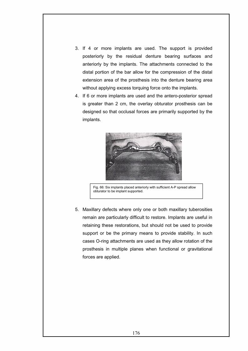
176
3. If 4 or more implants are used. The support is provided
posteriorly by the residual denture bearing surfaces and
anteriorly by the implants. The attachments connected to the
distal portion of the bar allow for the compression of the distal
extension area of the prosthesis into the denture bearing area
without applying excess torquing force onto the implants.
4. If 6 or more implants are used and the antero-posterior spread
is greater than 2 cm, the overlay obturator prosthesis can be
designed so that occlusal forces are primarily supported by the
implants.
5. Maxillary defects where only one or both maxillary tuberosities
remain are particularly difficult to restore. Implants are useful in
retaining these restorations, but should not be used to provide
support or be the primary means to provide stability. In such
cases O-ring attachments are used as they allow rotation of the
prosthesis in multiple planes when functional or gravitational
forces are applied.
Fig. 66: Six implants placed anteriorly with sufficient A-P spread allow obturator to be implant supported.

177
GENERAL OUTLINE OF PROSTHODONTIC REHABILITATION OF
SOFT PALATE DEFECTS
Velopharyngeal dysfunction may be congenital, developmental
or acquired, it affects all age groups
It may occur as insufficiency or incompetency.
Velopharyngeal Insufficiency: denotes speech and resonance
aberrations related to a congenital or acquired anatomic defect of the
soft palate that makes the sphincter incomplete such as that occurring
in cleft palate or post surgical resection
Velopharyngeal Incompetence: denotes dysfunction of an anatomically
intact velopharynx that occurs in patients with the following disorders.
The soft palate and pharynx are innervated by a nerve plexus
(pharyngeal plexus) including fibers originating from the IX, X, and XI
cranial nerves and possibly some fibers from the VII nerve. Any
disease or disorder that affects the normal function of any of these
cranial nerves or their central origins can have significant effects on the
function of the palatopharyngeal complex.
1. Traumatic brain injuries, cerebrovascular accidents or post
neurosurgical treatments of brain/ meningeal tumours.
2. Central or peripheral degenerative or metabolic disorders of the
nervous system such as – multiple sclerosis, Parkinsonism, bulbar
poliomyelitis, cerebral palsy, Amyotrophic lateral sclerosis, dystonia
and myasthenia gravis.
3. Muscle or connective tissue disease – myotonic dystrophy or mixed
connective tissue disorder.
Other conditions related linked to incompetence of anatomically
intact velopharyngeal valve: these are behavioral mislearning, tonsillar
upper poles hypertrophy, hypotonic (dyskinetic) velopharynx, overly
stressed velopharynx (wind instrument playing).
178
As general rule, palato-pharyngeal insufficiency is treated with a
pharyngeal prosthesis or speech bulb prosthesis if the surgical procedures
like palatal push back, pharyngeal flap or posterior wall implants cannot be
carried out.
Palatopharyngeal incompetence is treated with a palatal lift.
Prosthetic restorations of post cancerous defects, occurring in the soft
palate area vary according to the site and extent of such defects.
The most important factor pertaining to the type of prosthetic
treatment is the integrity and function of the posterior border of the soft
palate; the prime objective of treatment in patients with oronasal
communication is a return to the physiologic functions of mastication,
deglutition and speech. If these objectives are achieved the other
sequelae of surgical procedure such as seepage of nasal fluid into oral
cavity, and escape of food into the nasopharynx will normally be corrected.
Obturator prosthesis fabricated for patients with palatopharyngeal
deficits vary with the location and nature of the defect or deficiency. In
contrast with the obturator prosthesis constructed for hard palate defects,
prosthesis for palato-pharyngeal deficits must function in concert with soft
tissues displaying considerable movement.

179
CLASSIFICATION OF SOFT PALATE OBTURATOR PROSTHESIS: -
This classification has been given by Beumer and Curtis17 and is according
to the location and nature of defects of soft palate and palatopharyngeal
defects
Structures Involved Cause(s)
TOTAL SOFT
PALATE
DEFECTS
Entire soft palate Surgical excision of
neoplastic disease,
unoperated cleft palate,
surgically redivided cleft
palate
POSTERIOR
BORDER
DEFECTS
Median
defects
Posterior half of palate. Surgical excision of
neoplasia, post surgical
cleft palate with in-
sufficient length
Lateral
defects
Lateral half of soft palate
and often lateral
pharyngeal wall
Surgical excision of
neoplastic disease
SPECIAL
OBTURATOR
PROSTHESIS
Palatal lift All structures intact or
when posterior border
defect (combination)
Neurological disease,
Postsurgical cleft palate
with insufficient length
and movement.
Meatal Hard and soft palate Unoperated cleft palate
Surgical excision of
neoplastic disease.
180
B. ARAMANY MOHAMMED (1978) classified defects of palate as
i) Total resection of the soft palate retaining a part of the hard palate: -
In this type of resection, the soft palate is totally removed, including all its
muscles. The function of the superior constrictor muscle of the pharynx
remains intact. The prosthesis for such defects involves speech aid
prosthesis extending posteriorly from the base of the prosthesis into the
pharyngeal region separating the oropharynx from the nasopharynx. At
rest position, there is a space around the pharyngeal part of the prosthesis
to effect nasal breathing.
ii) Median resection of the palate: -
The resection may involve parts of the hard and the soft palate. However
the levators, tensor, uvula, palatoglossus and palatopharyngeous muscles
are left functionally intact. The normal physiologic movement of the palate
will take place on eliciting the velopharyngeal mechanism whereas; the
presence of the defect will make this movement functionally inadequate.
The anterior margin of the defect is not mobile, whereas the posterior
aspect of the defect will move superiorly and posteriorly, increasing the
size of the oronasal communication.
The prosthesis extension from the parent prosthesis passes through the
soft palate defect to permit the sphincter action of the margin of the defect
to produce an oronasal seal.
iii) Lateral resection involving approximately half of the soft palate: -
Lateral resection often jeopardizes the integrity of the remaining halves of
the muscles of soft palate. Since the palate is intended to function through
a paired mechanism, the loss of half of the mechanism drastically alters
the function of the palate during swallowing and speech.
It the defect is small, velopharyngeal closure may be effected without the
help of prosthesis. If the defect is large or the patient is unable to develop
compensatory movement, a retro velar speech aid is constructed. A

181
pharyngeal extension from the base of the prosthesis passes through the
defect till the potential space behind the remaining segment of the soft
palate. Velvopharyngeal closure is attained by the levator action of the
remaining soft palate and the contraction of the pharyngeal muscles
against the pharyngeal extension of the prosthesis.
OBTURATOR PROSTHESIS FOR SOFT PALATE DEFECTS: 17,135,136
Sharry 125 describes the pharyngeal obturators that are used in
patients with congenital or acquired soft palate defects to separate the
nasopharynx and oropharynx during speech and deglutition. The
prosthesis consists of a complete or partial denture base and a pharyngeal
extension that will not only physically modify the pharyngeal airway but
also provide an object against which the surrounding muscles can function
to provide a seal between the oropharynx and nasopharynx during function
1. Hinged Obturator: Delabarre and Snell first introduced it in early
1820’s. Modifications by Stearn and Kingsley made it the prosthesis of
choice in the latter half of the nineteenth century. In this type, the
pharyngeal section is attached to the prosthesis by means of a hinge.
The objective is to create a movable obturator that functions in a
manner similar to the normal soft palate. This obturator relies on the
activity of the superior pharyngeal constrictor muscles and residual soft
palate muscles to function.
Its success depends upon the muscle activity of the residual palate and
the stability and retention of the denture base, which has to support the
Fig. 67: Hinge type pharyngeal obturator

182
additional weight of the hinge and mobile obturator section. Also the shape
of the nasopharynx changes at rest and in function, hence, it is very
difficult to obtain adequate nasopharyngeal closure
2. Fixed or horizontal Obturator: Introduced by Suerson in 1868 and
advocated by Fitzgibbon in 1920’s. It is placed in a fixed position within the
pharynx at the site of maximal muscle activity or approximately the level of
the palatal plane. During physiologic function, the obturator is contacted by
the posterior pharyngeal wall and the lateral pharyngeal musculature, thus
creating a separation between the oropharynx and nasopharynx. It is the
most commonly used type.
3. Meatus Obturator – was introduced by Schialit in 1946 and is
described in detail later.
Beumer and Curtis17 have described obturation of acquired defects of the
soft palate in three stages.
1) Immediate surgical obturator
2) Delayed surgical obturator
3) Definitive obturator
Fig. 68: Fixed or horizontal pharyngeal obturator.

183
1) Immediate surgical obturator:
The principle advantage of immediate surgical obturator for soft
palate defects is support and retention of the surgical packing. Immediate
surgical obturators, constructed presurgically are approximations with
regard to the level of placement and the contours of the lateral and
posterior margins.
There are differences between surgical obturator for hard palate
defects compared to the ones for defects of the soft palate and the
contiguous structures as:
- The drape of the soft palate precludes the clinician from
obtaining the impression of the nasopharynx, where normal
velopharyngeal closure occurs and where the surgical obturator
should be located.
- Functional measurements of the velopharyngeal mechanism
cannot be recorded prosthodontically either prior to or during
surgery.
- Pharyngeal tissue peripheral to the defect will exhibit little
movement during function in the immediate postoperative
period.
- The extent of these tumours is more difficult to visualize; hence
it is more difficult to delineate the surgical margins
presurgically.
An extended impression, of the soft palate is obtained and the cast
is altered to correspond to the proposed defect. The plane of the hard
palate determines the superior- inferior plane of the obturator and that of
the soft palate determines the width. Adjustment at surgery is done to
avoid excessive tissue contact. It is kept 7 to 10 days post-surgically
following which, the prosthesis is removed along with the surgical packing,
and is altered by adding soft interim reline material for changed tissue
contacts. The patient is monitored with sequential appointments until the
definitive prosthesis can be constructed.

184
2) Delayed surgical obturator:
Patients with smaller defects of the posterior or lateral borders of
the soft palate often are best served with delayed surgical obturation as
the small defects are masked by postoperative oedema in the immediate
postoperative period. In edentulous patients, consideration should be
given to attaching the delayed surgical obturator to the existing maxillary
denture.
3) Definitive obturator:
Patient exhibiting considerable movement of the residual
palatopharyngeal complex during function have an excellent prognosis for
achieving normal speech with prosthesis.
If the patient is edentulous, the prosthesis can be attached to the
existing dentures. If the patient is dentulous a removable partial denture
framework retains the obturator. It is a fixed platform of acrylic resin that
provides surface contact for the remaining musculature of the
palatopharyngeal mechanism during function. However, a space exists
between the surrounding tissues structures and the prosthesis during rest.
Guidelines for location of the obturator segment of the prosthesis: -
- The obturator for an adult patient should be located in the
nasopharynx at the level of normal palatal closure.
- The inferior margin of the obturator should be placed at the level of
greatest muscular activity exhibited by the residual
palatopharyngeal complex.
- The inferior extension of the obturator will usually be an extension
of the palate plane as extended to the posterior pharyngeal wall.
- The superior margin of the obturator should not extend above the
level of muscular activity.

185
Design Considerations:
1. Support: it is provided by the following:
- Occlusal rests on natural teeth.
- Major connector.
- Denture bases.
2. Retention:
- Retentive clasps on the primary abutments.
- Skin graft – host tissue junction creates the retentive undercut.
- Residual ridges and hard palate in edentulous patients provide
retention.
- Indirect retainers on the secondary abutments away from the
fulcrum line prevent rotation of prosthesis away from tissue.
- Endosseous implants provide direct retention.
3. Stabilty is provided by the major and minor connectors and the denture
flanges which prevent lateral motion and distribute stress.
I) Prosthetic outline of total soft palate defects rehabilitation:
Impression procedure - (Functional impression technique):
First a diagnostic cast is obtained by making an impression in a
stock tray with palatal portion extended in wax. The cast obtained
will assist diagnostic procedure, tray preparation and establishing
design for cast partial denture framework.
The partial denture design must have provision for multiple
occlusal rests on either side of the fulcrum line and multiple
retainers with the retentive arm engaging distal undercuts. A wire
loop or tray resin is added to the framework as retentive meshwork
to approximate the area of the defect.
Next, modeling plastic is placed in the region of tray resin
for to purpose of border molding. The patient is instructed to flex

186
the neck fully to achieve contact of the chin to the chest. This
movement will establish contact of the posterior aspect of the
obturator with the soft tissue covering the anterior tubercle of the
atlas. Lateral aspects of the obturator are formed by rotation and
flexion of the neck to achieve chin contact with the right and left
shoulder respectively. The compound is then warmed and inserted
and the patient is asked to speak and swallow, so that the
remaining palatopharyngeal musculature is activated and shapes
the modeling plastic. Since swallowing precipitates a more forceful
closure it is performed at the end to avoid under extension.
A completed molding will appear dull, and is confirmed by
asking the patients to speak, swallow and to breath through the
nostrils to test the effectiveness of formed obturator. Speech should
sound normal, with the patient able to articulate plosive sounds
such as p and b and yet be able to form the nasal consonants m, n
and ng. If the position and contours are satisfactory, all extensions
are reduced approximately 1 mm with a sharp scalpel.
Next, mouth temperature thermoplastic wax is added to the
obturator, flamed, tempered and placed in the mouth. The
functions activating the palatopharyngeal musculature are
repeated, to reestablish the contours of the obturator. The use of
thermoplastic wax ensures against overextension. Adequate areas
of contact demonstrate a dull-stippled appearance, whereas a
shiny surface indicates a lack of contact. The obturator prosthesis
is left mouth for 5-7 minutes before removing it.
After removal from the mouth, the prosthesis is checked for
overextension. Any area in which, modeling plastic is visible, the
plastic is scrapped and new layer of wax is applied. The wax is
flamed and tempered, before reinserting. When speech and
swallowing are normal and the contour of the obturator appears
adequate the prosthesis is tempered in a water bath and replaced
in the mouth for an extended period (1 to 3 hours). The patient is
instructed to wear the prosthesis without removal and is
187
encouraged to speak, swallow and perform previously described
movements.
Size and position of the obturator: The lateral dimensions of the
obturator the determined by lateral and posterior pharyngeal wall
movement if the obturator is positioned correctly at the level of
greatest internal and posterior pharyngeal wall movement a
superior extension of approximately 10 mm into the nasopharynx is
sufficient. A further superior extension, may add additional width
and extra weight, and will occlude the nasopharynx resulting in
difficulty with nasal breathing and hyponasal speech. Conversely, if
the obturator is placed too low into the oropharynx, tongue function
will be disrupted and gagging may be precipitated.
Processing and delivery of the prosthesis
The obturator is processed in a customary manner, with either heat
activated or auto - polymerizing methyl methacrylate. Following
processing, gross excesses is removed. The oral surface of the
obturator should be concave to provide adequate space for the
tongue. The superior surface should be convex and well polished to
facilitate the deflection of nasal secretions into the oropharynx.
Also, the lateral margins of the obturator are lightly polished to
improve hygiene and the deflection of secretions.
Speech evaluation following obturator placement
Speech is usually within normal limits immediately following
placement of prosthesis for acquired soft palate defects. As these
patients produced normal speech prior to surgical impairment, the
prosthodontist will often require the assistance of a speech
pathologist to evaluate articulation errors and inappropriate nasal
resonance.
2. Obturation of soft palate posterior border defects
The objective for obturation of these defects is similar to the
obturation of total soft palate defects. However, the prosthetic
approach differs since the remaining intact position of the soft

188
palate must be circumvented to place the obturator at proper level
in the nasopharynx.
There are two basic approaches for construction of
obturators for posterior order defects. First method is to record the
soft palate at rest and after the residual soft palate is circumvented,
the obturator is extended superiorly behind the soft palate to the
proper level for obturation. This is basically suitable for short taut
palate.
Second method is to displace the residual soft palate
superiorly with the extension, to place the obturator in the proper
position into the nasopharynx. Such prosthesis is termed palatal lift.
Patients with long or immobile palates should be considered for
palatal lift prosthesis.
a. Median Posterior border defects
The preliminary impression should include the residual soft
palate, plus the defect posterior to the soft palate. The cast
obtained will serve diagnostic purpose and for adaptation of the
wire loop extension for the obturator. Next functional impression is
made as described for total soft palate defects.
The level of placement of the obturator is the same as in
patients with a total soft palate defect. However, a more lengthy
superior extension may be necessary to reach the level of normal
closure, since direct visualization of the area of normal
palatopharyngeal closure may not be possible. If the posterior
border of the resected soft palate is severed, and exhibits little
motion, it may be necessary, to extend the obturator across the
nasal surface of the soft palate to obtain retention.
After processing and prior to insertion, the superior surface
of the obturator is trimmed and rounded slightly to form a convex
surface and the extension of resin across the soft palate is thinned
as much as possible. This extension will be approximately 10 mm
wide and 2 to 3 thick, also the nasal extension may require, to be
reduced to facilitate insertion.

189
If the level of normal palatopharyngeal closure is
considerably above the posterior border of the soft palate, the
inferior surface of the obturator may be reduced further.
b) Lateral posterior border defect
In these situations the post-surgical relationship forces the
clinician to engage the opposite lateral pharyngeal wall behind the
soft palate to achieve palato pharyngeal closure.
Methods of fabrication:
A partial or complete prosthesis is constructed before the
fabrication of obturator. The retention of the obturator is best
provided by a wire loop attached to the conventional prosthesis. In
situations where soft palate exhibits little or no motion a cast
meshwork may be constructed as a component of the partial
denture framework. After the conventional prosthesis is fabricated
and adjusted, the retention for the obturator is adjusted.
The obturator is fabricated following functional pharyngeal
impression techniques. There must be adequate movement of the
residual palatopharyngeal mechanism to control nasal airflow. In
defects with limited mobility during palatopharyngeal function,
continuous contact is maintained between these tissues and the
obturator both at rest and during function. Generally, following
delivery the speech is hyponasal; the lateral extensions of the
obturator are reduced gradually, until nasal breathing is acceptable.
Implant Retained and Supported Obturator prostheses:
In edentulous patients with soft palate defects, the posterior palatal
seal area is altered making it difficult to obtain and maintain peripheral
seal and the long lever action and gravitational force further decreases
retention. If the posterior palatal seal area is relatively intact then, two
implants in the premaxillary segment will suffice. If the posterior palatal
seal area is compromised and residual palatal structures provide
inadequate support and stability, then four or more implants are
required.

190
These osseointegrated implants enable the design and fabrication
of complete overlay dentures with retentive capabilities similar to
prosthesis for dentulous patients with fixed partial dentures.
Maximizing the antero-posterior spread of the implants improves
the load distribution. The design of the prosthesis is based on the
status of opposing dentition, number and length of implants, quality of
bone, antero-posterior spread and the size of the defect.
The use of attachments like the Hader bar anteriorly and the ERA
posteriorly allow the prosthesis to rotate around a predictable axis,
permitting residual denture base area to aid in the support of occlusal
loads.
4. Special Obturator Prosthesis 10,16,17,72,120,129,140
The palatopharyngeal mechanism or velopharyngeal valving
mechanism regulates the resonation and speech utterance and
partakes in non-speech oral activities such as swallowing, blowing,
sucking and whistling. Velopharyngeal dysfunction implies the
presence of hypernasality, inappropriate nasal escape, and decreased
air pressure during the production of oral speech sounds.
Compensatory articulations in the form of secondary glottal, lingual and
labial errors are often present. The following modalities are used to
correct these.
a) Palatal lift prosthesis
It was first advocated by Gibbons and Bloomer (1958).51
Fig. 69: The use of Hader Bar anteriorly and ERA attachment posteriorly allows the prosthesis to rotate around a predictable axis, permitting the residual denture bearing surfaces to aid in support of the occlusal loads. a – At rest, b- Under load.

191
There are two prosthodontic procedures available in the treatment of
patients with palatopharyngeal inadequacies.
i) The palatal lift prosthesis.
ii) Combination palatal lift/Pharyngeal section prosthesis.
i) The Palatal lift:
It used to elevate the soft palate to its maximal position during normal
speech and deglutition enabling closure by pharyngeal wall actions.
ii) The combined palatal lift:
It is preferable, if the soft palate is insufficient to achieve proper
palatopharyngeal closure. The prosthesis will elevate the soft palate and
also obturate the palatopharyngeal gap, thereby stimulating
palatopharyngeal activity and pharyngeal muscle contraction.
Fig. 70: In an anatomically normal but paralyzed soft palate, a palatal lift prosthesis is used to get velopharyngeal closure. Pp – palatal plane, ta- median tubercle of atlas.

192
Evolution of the palatal lift:
It has evolved from speech problems associated with insufficient
velvopharyngeal closure. These speech difficulties have their origin in
neuromuscular deficiencies, injury to the soft palate, paralysis or
inadequate length, inadequate movement of the soft palate following the
surgical closure of a congenital cleft palate or poliomyelitis, and the
submucous cleft palate. Adequate lateral wall movement is necessary for
lift to be effective.
Parts of a lift prosthesis:
Lamina: The portion of prosthesis, that underlines elevates and
supports, neurologically impaired velum. It consists of
i] Base - that underlies the anterior one third of the velum and is
attached to the basic prosthesis.
ii] Midsection
iii] Vertex - That underlies a variable portion of the terminal one third of the
velum, and contacts with the palatopharyngeal musculature.
Objectives of palatal lift and combination prosthesis:
Fig. 71: in a congenital anatomic insufficiency of velopharynx, a palatal lift plus obturator is used to elevate the soft palate and obturate the velopharyngeal space. Pp – palatal plane, ta- median tubercle of atlas.

193
- To reduce hypernasality (nasal escape of air) by palatal elevation.
- To reduce the degree of palatal disuse atrophy.
- To increase palatopharyngeal function by constant and continuous
stimulation.
- To increase neuromuscular response by gentle stimulation and
speech exercise.
- To assist in the repositioning of the tongue.
Advantages of palatal lift and combination prostheses.
- The gag response is minimized because of the superior position
and the sustained pressure of the lift portion of the prosthesis
against the soft palate.
- The physiology of the tongue is not compromised because of the
more superior position of the palatal extension.
- The access to the nasopharynx for the obturator is facilitated.
- The lift portion may be developed sequentially to aid patient
adaptation to the prosthesis.
- Application to a diverse patient population.
Disadvantages / Contraindications:
- When adequate retention is not available for the basic prosthesis,
- If the palate is not displaceable
- Uncooperative patient.
Pre-requisites of the palatal lift - pharyngeal section combination
prostheses.16
i) The maxillary portion of the prosthesis is designed to achieve optimal
retention and stability.
ii) The lift portion of the prosthesis should be placed so that palatal
elevation occurs in the area where normal palatopharyngeal closure takes
place.
iii) Elevation of the soft palate should be gradual so that the soft palate
becomes less resistant to displacement.
iv) The pharyngeal section should be placed in the region where
constriction of the posterolateral pharyngeal wall takes place to encourage
muscle stimulation and activity.

194
v) The reduction of the pharyngeal section, when indicated should be
gradual.
vi) Speech therapy, including lip, tongue, and palatal exercise and
placement should be instituted in conjunction with the construction and
insertion of prosthesis.
Fabrication of palatal lift Prosthesis :
Before starting the fabrication, the prosthodontist must determine
the potential amount of force that will be required to lift the soft palate to
create the desired effect. A mouth mirror or tongue blade should be used
to check the tonicity of the soft palate. Care should be taken during this not
to touch the dorsum of the posterior part of the tongue and/or the tonsillar
pillars to avoid gagging response from the patient. The mirror easily
displaces the soft palate of patients with a flaccid paralysis. However, if the
soft palate resists displacement because of fibrosis or tonicity of the
muscles, a palatal lift may not be successful, as a lot of force will be
required to lift the palate leading to a prosthesis that cannot be kept in
place or in pressure irritation and ulceration of the mucosa of the soft
palate.
Also, the movement of the pharyngeal wall should be clinically
evaluated by asking the patient to say “ahhhh” with the mouth wide open.
If there is complete lack of soft palate and lateral pharyngeal wall
movement, then the prosthesis will be required to occlude the entire
velopharyngeal port to eliminate hypernasality, which will lead to
elimination of nasal breathing.
Since, velopharyngeal incompetency is seen in patients with
neurological deficits; it is important to determine whether they have the
dexterity to manipulate the prosthesis intraorally.
In young patients and patients with needs which may change it is
advisable to make the prosthesis entirely in acrylic. Initially the primary
impressions are made in irreversible hydrocolloid. Care should be taken in
patients with neurologic deficits as protective reflexes may be lacking and
airway obstruction is major risk. The impression must cover areas at least
2cm posterior to the fovea palatini. The tray must support the impression
material so that the soft palate is displaced by the impression. Some
patients with long arches require the use of custom trays.
195
Principles for retention of palatal lift prosthesis -
Clasps in palatal lift prosthesis not only retain the prosthesis but
also support the lift portion in its functional position. The ideal position of
the retentive clasps to engage is the disto-buccal undercut on the most
posterior tooth on either side of the arch. This places retentive elements as
close to the cantilever of the lift portion as possible.
- If wrought wire clasps are used, they should engage 0.04 to 0.05
inch of undercut. This is required in molars especially as the length
of the clasp arms makes them flexible.
- If orthodontic brackets are used for retention, the clasps must
approach from the distal aspect and continue anteriorly for at least
two additional teeth to allow the patient to grasp the clasp and
reflect it laterally to disengage the lift. An 18-gauge wire should be
used.
- If sufficient retentive undercut is not available on the most posterior
teeth, additional retention may also be gained by placing composite
resin in the area of the tooth where increased retention is required.
It is also very important to have indirect retention as far anteriorly as
possible to make the retentive clasps effective. The mesial marginal fossa
of the first premolar serves as an effective site as it is sufficiently anterior
to the fulcrum line.
After mouth preparation, the final impression is made and framework
fabricated. The retentive meshwork or wire loop should extend from the
base portion approximately 2 cm. This length provides enough support for
the lift moulding process and is not long enough so as to interfere with the
processing. The loop should be on the same plane as the hard palate but
should have slight relief between itself and the cast to allow for the
impression material and ultimately the acrylic resin to coat the superior
surface.
After the framework is physiologically adjusted the lift generation is
done. It is extremely important that a speech pathologist is present during
this procedure. Various diagnostic aids can be used to assess during the
procedure, whether the lift is adequate and sufficient velopharyngeal
closure has been achieved.

196
- The framework is placed in the mouth and modeling plastic is
added to the retentive loop, shaped and flamed to create a smooth
surface and then chilled before placing it in the patient’s mouth.
The first layer should cover the loop evenly and extend several
millimeters beyond. If softened compound is placed in the mouth,
then the soft palate will displace it downward and the lift action will
not be achieved. The goal of the procedure is to displace the soft
palate superiorly and can be achieved by placing hardened
compound.
- The patient is allowed to wear the palatal lift for a few minutes at
this stage to get used to the sensation of the lift.
- Small additions are then made to the compound posteriorly until the
soft palate is brought into light contact with the posterior pharyngeal
wall.
- At this stage there is gap between the soft palate and the lateral
pharyngeal walls. So, the lateral extent of the lift should be
increased sufficiently to close the lateral port.
- Following each addition, the patient is asked to breathe through the
nose and attempt speech.
- Care should be taken not to overextend the compound orally as
any contact of the compound with the dorsum of the posterior part
of the tongue will elicit the gag reflex.
- Enlargement of the lift ceases when the speech pathologist is
satisfied with the result, or when the retentive limit of the clasps is
reached and the soft palate dislodges the prosthesis by the
downward force.
- If the patient cannot breathe nasally, then some compound is
removed from the lateral aspects of the lift until breathing is
restored. Ideally, the lateral pharyngeal wall movement allows the
maintenance of lateral breathing ports that close down, when the
patient speaks. The nasoendoscope can be used very effectively to
check for lateral wall movement.
- Sometimes, entire occlusion of the nasal airway is required to
eliminate hypernasality.
- Finally, the entire surface of the modeling compound is reduced by
1-2mm and impression wax is added and tempered. After placing in
197
the mouth, the patient is asked to speak, swallow water and move
the head in all directions to form the wax.
- The lift is removed after 5 minutes and any pressure spots where
compound is exposed are relieved and more wax is added and the
previous step repeated.
- The palatal lift portion is replicated in acrylic resin ensuring that
there are no rough or sharp edges present.
Palatal Lift prostheses in edentulous patients: 120
Conventional palatal lift prosthesis must be securely retained in the
maxillary arch to resist the rebound of the lift. This situation is very difficult
to achieve when the patient is edentulous and there are no teeth to utilize
for retention. Therefore, in edentulous patients palatal lift prosthesis must
include as movable palatopharyngeal section connected to the denture
with Ni-TI wires. The elastic wire shows a unique stress-strain curve with a
plateau of 2% to 5 % strain and a return to almost 0 % strain as the stress
reduces to zero.
Technique:
§ Preliminary impressions are made in irreversible
hydrocolloid.
§ Referring to the cephalogram, soft palate contour is altered
in the cast to simulate the contour of the raised soft palate.
§ Custom tray is prepared for the final impression.
§ Final impressions are made in conventional way and casts
poured.
§ After jaw relationship records and arrangement of teeth, the
palato-pharyngeal section is waxed keeping two openings
to reduce the weight.
§ Process the palatomaxillary section (complete denture) and
the palatopharyngeal section separately. On the master
cast, embed Nickel- Titanium wires in both sections using
autopolymerizing resin
Insertion and Patient Instructions:

198
- The effectiveness of the lift is again evaluated at the insertion
appointment and a pressure indicating paste is used to detect
localized excessive pressure. Only these areas should be reduced
slightly. Arbitrary trimming should not be done.
- The patient should be trained to place and remove the prosthesis
and instructed to wear the lift prosthesis only during waking hours.
- Patients for whom the nasal airway has been completely blocked to
correct hypernasality, should be instructed to use the prosthesis
only when they need to speak and remove during eating food.
- The patient should be seen within 2 –3 days after delivery of the lift.
It’s use should be limited to day time as the mucosa of the palate
must be given enough time to recover from the coverage and pressure.
Also the clasped abutment teeth are at risk of supraeruption due to the
high force application by the retainers and need relief from these forces.
LaVelle and Hardy (1979) 72 defined three satisfactory outcomes for palatal
lift prostheses:
An optimal result occurs when the prosthesis results in
palatopharyngeal port closure during speech production except in
association with production of nasal consonants; that is, the resulting
pattern of closure would be essentially normal.
The result is considered successful when there is palatopharyngeal
closure throughout speech production. These patients generally end up
hyponasal with their prosthesis in place. This is because they are fully
closed and are not able to get airflow when saying their nasal sound as m,
n and ng.
The result is considered only desirable when the palatopharyngeal
port area is reduced so that incompetency is a relatively minor speech
physiology problem.These patients are still slightly hypernasal because the
prosthodontist was unable to apply adequate lifting pressure in the optimal
location to completely occlude the palatopharyngeal port.
b) Meatus-type obturator prosthesis 125,124,136

199
Schialit first described this in 1946. The meatus obturator only
provides a static obturation and is not dependent on the surrounding
muscle activity to provide a more physiologic separation between the oral
and nasal structures. It is not located in a region of muscle activity.
Therefore, speech therapy is not effective in refinement of speech as seen
with fixed and hinged pharyngeal obturators and it is not as effective as the
horizontal obturator in cleft palate patients. The need for improved
retention and stability of prosthesis, may suggest its use in some patients.
Obturator of choice for edentulous patients with acquired defects of
the soft palate when retention is a problem as the hinged and fixed
obturators create a long lever arm that encourages dislodgement of the
denture base. These patients with acquired defects retain normal speech
articulation patterns but lack the ability to obstruct the passage of air into
the nose. The change in voice quality is less objectionable in patients with
acquired defects than in patients with congenital defects that have not
developed the oral and pharyngeal function necessary for good speech
articulation.
May be used for patients with extensive defects of the soft palate exhibiting
active gag reflex.
It establishes closure with nasal structures, at a level posterior and
superior to the posterior terminus of the hard palate. The closure is
established against the turbinates, residual vomer and the roof of nasal
cavity. The posterior nasal choanae determine the shape of the meatus
obturator. These openings are bounded laterally by the medial surface of
the medial pterygoid plate of the sphenoid bone, inferiorly by the horizontal
Fig. 72 : Meatus type Obturator
200
plate of the palatine bone, medially by the vomer bone, and superiorly by
the vomer and sphenoid bones immediately inferior to the sphenoid sinus.
These structures are covered by the respiratory epithelium. The
pharyngeal canal that carries the pharyngeal nerve and artery exits
through the sphenoid bone at the most superior extent of the choanae.
There are no muscles or muscle attachments at the level of the posterior
choanae.
In the patient with edentulous maxillae where retention of the
prosthesis is at best difficult, the meatus obturator is above the denture
base rather than posterior to it, as seen with other types of obturators. This
relationship lessens the lever action of the obturator on the denture base.
The posterior choanae of the nares also tend to be narrow in comparison
with the nasopharyngeal size, and the meatus obturator can be made
smaller than a horizontal obturator. The associated reduction in weight and
the decreased lever action of the meatus obturator creates a more stable
prosthesis. In addition, the floor of the nose or scar band of the resected
soft palate can often be engaged from above to enhance retention.
The meatus obturator can only be used in patients with an absence
of mobile soft palate in the midline, as the vertical component of the
obturator will interfere with the soft palate function in patients with
remaining soft palate movement. The meatus obturator is contraindicated
for use in patients whose soft palate defect is narrower than the
nasopharynx in the region of the posterior choanae. A narrow palatal
defect limits the width of the impression and subsequently the width of the
obturator. The meatus obturator is also contraindicated when the path of
insertion of the complete denture is different from the vertical path of
insertion necessary for the meatus obturator. A prominent anterior residual
ridge with labial undercut will prevent seating. Alveoplasty should be
considered but weighed against the subsequent reduction in retention.
Fabrication of Meatal obturator prosthesis:
The fabrication can be achieved in several ways. One of the more reliable
methods entails a corrective cast impression technique at the final wax try
in stage for the complete denture. If the patient’s existing denture is
adequate, the obturator portion may be attached as an additive procedure.
A technique for addition of a meatus obturator to an existing or new
denture base is described.
201
An 18-gauge wire loop is added to the posterior border of the denture with
autopolymerizing acrylic resin. The loop should be extended horizontally to
pass posterior to the remnant of the soft palate. The loop is then extended
vertically into the area of the posterior nasal orifices. The loop should not
contact mucosa at any point and should be narrow enough at the isthmus
to avoid contact with the functioning residual muscles.
A primary modeling compound impression is made by adapting the
softened compound to the supporting loop in sufficient quantity to obturate
the loop in all areas. The denture with softened compound is completely
seated. On cooling, the denture is removed and the compound impression
is reduced in size to ensure absence of tissue contact.
The primary compound impression is then border molded using
additional compound of a lower working range. Border seal will be evident
when the posterior choanae are obturated, as noted by positive tissue
contact and the patient’s inability to inhale or exhale through the nose.
Head, speech and swallowing movements are unnecessary as there are
no movable tissues in this area.
Certain anatomical landmarks can be identified in the impression.
Two lobes denoting the right and left nasal cavities project anteriorly
divided by a groove caused by the posterior margin of the vomer bone.
Lateral depressions are caused by the inferior turbinates. Posterior to the
depression of the turbinates outlines of the orifices of the eustachian tubes
may be evident. The impression should be reduced to avoid blocking the
tube orifices.
When maximum extension has been achieved, the compound
impression is reduced uniformly to provide space for the final impression
material. To assure positive tissue contact, a functional impression
material such as mouth temperature wax is used. The final impression
material should remain in place for 5-7 minutes. On removal, it should be
evaluated for uniform thickness and positive tissue contact.
A cast is poured around the completed impression. The wax and
compound are removed, the cast painted with a separating medium, and
autopolymerizing/ light cure resin processed to the retentive loop.
On removal from the cast, the processed obturator is reduced from the
posterior aspect to minimize bulk, and the obturator is lightly polished.
The prosthesis is inserted in the mouth to verify complete
obstruction of the nasal airway. Vent holes are then placed through the

202
obturator in the area lateral to the contact with the vomer. The vent
openings are placed in the superior third of the anterior surface and angled
downward at an angle of 45 degrees to the posterior surface. This
downward angulation of the vents minimizes the chances of regurgitation
of food and liquid into the nose during swallowing.
The vents are enlarged gradually until breathing through the nose
becomes comfortable. If the quality of speech has deteriorated significantly
with the enlargement of the vents, autopolymerizing acrylic resin may be
added to reduce the vent openings until an acceptable level of speech
versus nasal airway has been attained.
On insertion of the completed prosthesis, instructions should be
given for its use. The possibility of leakage of food and liquids into the
nasal cavity should be emphasized, and the need to remove the prosthesis
frequently for hygiene should be stressed. An erect head position while
eating and drinking may minimize leakage. Mucous build up on the anterior
side of the obturator may necessitate more frequent cleansing. Removal of
the prosthesis at night should be encouraged. The need for regular
maintenance care to assess the adaptation of the prosthesis and evaluate
the health of the oral and nasal structures should be emphasized.
On placing the prosthesis, the nasality should improve, only the
articulative defects remains, and these are not as unpleasant because of
normal nasal quality.
Advantages:
q Meatal extension is not lengthy and is quite thin in anterior -
posterior dimension.
q Light in weight
q Downward displacement force from the obturator extension is
closer to the supporting tissues of the parent prosthesis.
Disadvantages:
q Nasal air emission is not controlled.
q Hyponasal speech and impaired nasal respiration.
q Distortion in nasal resonance because oral cavity and oropharynx
are increased in sizes and nasal cavity is reduced
proportionately.

203
q The meatus obturator interferes with the normal physiologic flow of
mucous posteriorly from the nose into the oral cavity.
q It may cause constant irritation to the sensitive respiratory mucosa.
Although the meatus obturator has not gained widespread acceptance for
use in cleft palate habilitation as originally intended by Schialit and Sharry, it
may still be useful in the treatment of edentulous and partially edentulous
patients with acquired soft palate defects where retention and stability of the
prosthesis are difficult to achieve. The meatus obturator can result in a more
stable maxillary prosthesis and permit acceptable speech for these patients.

204
The cleft lip and palate deformity is a congenital defect of the
middle third of the face, consisting of tissues of the upper lip or palate. The
aetiology has been discussed in the discussion about the development of
the palato-maxillary region.
Treatment for cleft lip and palate is unique in that it includes
various health disciplines, which are interdependent and interrelated.
Hence a team approach based on total patient care will enhance the level
of rehabilitation.
Classification of cleft lip and palate
Numerous methods of classification have been proposed for these,
congenital anomalies of the middle third of the face. The method proposed
by Stark is the most widely used today, with that proposed by the Cleft
palate association being next common in usage.
Classification by Olinger95
Class I - Fissure in the azygos uvulae
Class II – Fissure in the uvula

205
Class III – Fissure in the soft palate
Class IV – Fissure in the soft and hard palates
Class V – Unilateral cleft fissure in the soft and hard palates through the
alveolar ridge at the junction of the maxilla and premaxilla, accompanied
by a cleft of the lip.
Class VI – Bilateral cleft, fissure in the soft and hard palates through the
alveolar ridge, involving both sides of the premaxilla, freeing the
premaxillary bone with a double cleft lip.
Fitz – Gibbon’s Classification 50
Type I – Cleft of the soft palate only
Type II - Cleft of the soft and hard palate
Type III – Cleft of the soft palate, hard palate and unilateral extension on
one side of the pre- maxilla involving the lip as unilateral hare -
lip, sometimes, extending upto the nostril for varying distances.
Type IV – Cleft of the soft palate, hard palate and bilateral extension
through both sides of the premaxilla leaving an island attached
to the base of the septum and bilateral hare-lip extending upto
both sides of the nostril.
These are further described as congenital, acquired, post operative
and dentulous or edentulous.

206
.
Cleft Palate
Association
STARK VEAU
Pre Palate
Pre Palate
Pre Palate
Pre Palate
Primary palate
Subtotal unilateral
Subtotal bilateral
Total unilateral
Total bi-lateral
Palate
Palate
Palate(Sub-
mucous)
Secondary palate
Subtotal
Total
Class I
Class II
Pre palate
and palate
Pre palate
and palate
Primary & Secondary
Total unilateral
Total Bilateral
Class III
Class IV
DIAGNOSIS AND TREATMENT PLANNING INCLUDES
- Case history: includes general and dental case history.
- Impressions for study cast,
- Intraoral wax occlusal registration.
- Radiographs -Intraoral full mouth, bitewings, occlusal x-rays.
- Cineradiography - to record on film the function of the mandible,
tongue, velum and surrounding tissue during phonation blowing
and swallowing.
- Laminography - For the study of cranial facial growth and
velopharynx orifice size during a sustained sound.
- Pantomography : Used for clinical diagnosis of the oral facial region
and growth appraisal.

207
- Clinical examination of patients: includes both hard and soft tissue
examination.
- Photographs: Intraoral and facial color photographs for diagnosis,
teaching and illustration of before and after treatment.
- Speech recordings: which includes disc, wire or tape recording by a
speech therapist. & sound spectrographic recording.
- Other investigations: measurement of nasal and oral pressure and
flow, otologic and hearing examinations.
- Psychologic and social considerations
Analysis of all factors pertinent to the patient psychosocial status, at
this particular stage in the entire structure of therapy, must be integrated
with the diagnostic data accumulated.
Social services should be available to enable the patient to make full
use of medical dental and speech care both preventive and the
therapeutic, so that he can achieve the fullest possible, physical emotional,
and social adjustment.
General outline of prosthetic management of cleft lip and palate:
Indications for Prosthesis:
1. In Unoperated patients
- Wide cleft with deficient soft palate
- Wide cleft of Hard palate
- Neuromuscular deficiency of soft palate and pharynx
- When patients are high anesthetic risk cases.
- When delayed surgery approach (Zurich Approach) is followed.
- In cases where combined prosthetic and orthodontic appliances
like expansion prosthesis are to be used to improve spatial
relations prior to surgery.
2. Indications of prosthesis in operated palates:
Patients with hypernasality and inadequate speech following push
back and pharyngeal flap procedures.
Contraindications for prosthesis:
a. When surgical repair is feasible and when surgical closure of the
cleft will produce anatomic and functional repair.
208
b. A mentally retarded patient who is not capable of controlling and
taking care of his appliances.
c. Uncooperative patient
d. Rampant caries and periodontal breakdown situations
e. When experienced prosthodontic help is unavailable
f. The edentulous condition is not a contraindication for speech aid
prosthesis.
Goals and objective of prosthetic treatment
- It should aid in restoring the basic function of mastication,
respiration, phonation and deglutition.
- It must be worn by the patient without discomfort or damage to the
supporting and surrounding structures.
- It should be shaped so that it will give the remaining anatomic
structures an opportunity to regulate efficiency the functions of
speech, breathing and swallowing without any impediment to these
functions.
- It should be of simple, sturdy construction with special attention to
retention, occlusion and cosmetics.
PROSTHESIS FOR CLEFT LIP AND PALATE
1) For Infants
2) For Young Children and Adolescents
3) For Adults
General Considerations For Impression In Cleft Palate Cases
a) Impressions for infants
Maxillary and mandibular impression trays for infants can be
constructed by adapting a piece of baseplate wax against the ridge.
This wax patterns is then processed in acrylic resin. This can be
repeated in other cases to collect additional trays, for future use.
Also, pre-made trays can be used to make a primary impression.

209
TECHNIQUE :
An irreversible hydrocolloid material is used for impression.
The amount of water used for this is 5/6th of that recommended by
the manufacturer, and water is used at 100ºF in order to speed up
the setting of the material. The maxillary impression is made with
the infants head tilted at a downward angle of 15 degrees. This
position make's it possible to maintain a direct view of the oral
cavity at all times and it directs the flow of material towards the
oropharyngeal space.
At least 4 assistants should be available to
i) Hold the infant’s head.
ii) Depress the tongue and hold the suction.
iii) Hold the infant’s body and face
iv) Mix the impression material.
Proper instruments should be available, to gain access to material
should it be dislodged and enter the nasal or oral pharynx. The
tray should not be over packed, nor should too much force be
applied in placing the tray in position. The part of the tray that will
be directly over an undercut should contain less of the impression
material.
b) Impressions in older children and adults
The following suggestions should be kept in mind.
i) If the patient is a child, he should be given the opportunity
to see and examine the tray. He should be told that his
utmost co-operation is needed; otherwise it will be
necessary to make several impressions.
ii) The patient should be empty stomach.
iii) A topical anesthetic is applied to a child who has a
severe gagging reflex.
iv) The tray should not be over loaded. Excess material in
nasopharynx will increase difficulty to removing the
impressions without a fracture.
v) All oral perforations, which are small, should be packed
with gauze that has been saturated with petroleum jelly.
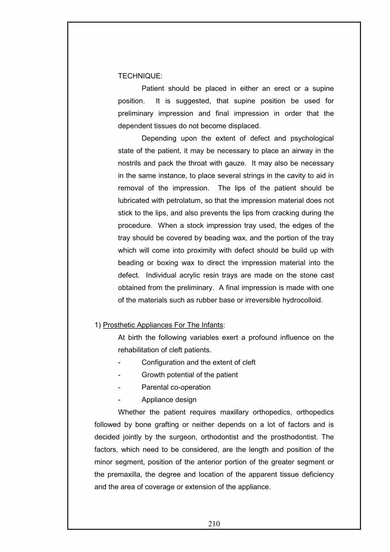
210
TECHNIQUE:
Patient should be placed in either an erect or a supine
position. It is suggested, that supine position be used for
preliminary impression and final impression in order that the
dependent tissues do not become displaced.
Depending upon the extent of defect and psychological
state of the patient, it may be necessary to place an airway in the
nostrils and pack the throat with gauze. It may also be necessary
in the same instance, to place several strings in the cavity to aid in
removal of the impression. The lips of the patient should be
lubricated with petrolatum, so that the impression material does not
stick to the lips, and also prevents the lips from cracking during the
procedure. When a stock impression tray used, the edges of the
tray should be covered by beading wax, and the portion of the tray
which will come into proximity with defect should be build up with
beading or boxing wax to direct the impression material into the
defect. Individual acrylic resin trays are made on the stone cast
obtained from the preliminary. A final impression is made with one
of the materials such as rubber base or irreversible hydrocolloid.
1) Prosthetic Appliances For The Infants:
At birth the following variables exert a profound influence on the
rehabilitation of cleft patients.
- Configuration and the extent of cleft
- Growth potential of the patient
- Parental co-operation
- Appliance design
Whether the patient requires maxillary orthopedics, orthopedics
followed by bone grafting or neither depends on a lot of factors and is
decided jointly by the surgeon, orthodontist and the prosthodontist. The
factors, which need to be considered, are the length and position of the
minor segment, position of the anterior portion of the greater segment or
the premaxilla, the degree and location of the apparent tissue deficiency
and the area of coverage or extension of the appliance.

211
TYPES OF APPLIANCE
i) Active or expansion type
ii) Passive or holding type
The type of appliance to be placed will be determined by the configuration
of the defect.
i) Active/Expansion Type
it is used if any degree of collapse is present.
- If the collapse appears primarily in the anterior region a fan type
of appliance is used.
- If the collapse of the arch is throughout its length a straight
jackscrew appliance is used
ii) Passive/Holding type:
Indicated if the cleft configuration is wide or the segments appears in an
ideal relationship
All appliances, whether active or passive are fabricated and
inserted prior to lip closure. The primary purpose of the appliance prior to
lip closure is not to proliferate tissue or initiate growth but to guide the
maxillary segments into proper spatial position with each other and with
the mandibular arch.
Salient feature regarding infant appliances:
o Active or holding appliances can achieve and maintain ideal arch
configuration in patients with complete clefts of the lip and palate.
o Once the lip has been surgically closed, the greatest tendency for
additional collapse is seen in those who presented initially with
some degree of arch collapse.
o A high degree/percentage of success is achieved in patients whose
initial arch configuration is wide.
o Lip closure can increase deformation or arch collapse unless
controlled by appliances.
o Parental, co-operation is essential for successful treatment.
The moulding pressure of the surgically closed cleft lip along with
the appliance helps to create an ideal arch form based on the Wolf’s law
that the functional stresses shape bone.

212
Nasoalveolar Molding in Early Management of Cleft Lip and Palate 69,135,145
The basic goal of any approach to cleft lip, alveolus, and palate
repair whether for the unilateral or the bilateral anomaly, is to restore normal
anatomy.
Ideally, deficient tissues should be expanded and malpositioned structures
should be repositioned prior to surgical correction. This provides the
foundation for a less invasive surgical repair. Historically, the use of
presurgical infant orthopedic (PSIO) appliances, or molding plate therapy,
has aided significantly in reducing the size of clefts of the alveolus and hard
palate prior to surgery. Since its introduction by McNeil in 1950, various
techniques for molding the intraoral alveolar segments closer together in
unilateral and bilateral cleft situations have been described (Mylin, 1968;
Latham, 1980).
PSIO appliances are generally consist of three components- A bulb
prosthesis made of acrylic resin which fits on the protruding or laterally
displaced premaxilla held in place by elastic straps attached to the bonnet
for extra oral anchorage. Although controversy surrounds the use of PSIO
devices in conjunction with various surgical protocols when employed to
move only the alveolar segments closer together, this text describes a new
approach of presurgical nasoalveolar molding (PNAM) therapy developed at
the Institute of Reconstructive Plastic Surgery at New York University
Medical Center.
PNAM includes not only the reduction of the size of the intraoral
alveolar cleft through the molding of the bony segments, but also the active
molding and positioning of the surrounding soft tissues affected by the cleft,
including the deformed soft tissue and cartilage in the cleft nose. This is
accomplished through the use of a nasal stent that is based on the labial
flange of a conventional oral molding plate and enters the nasal aperture.
The stent provides support and gives shape to the nasal dome and alar
cartilages. Presurgical nasoalveolar molding may be successfully
employed in the early management of the both the unilateral and bilateral
cleft anomalies in newborns.
In the bilateral cleft condition presurgical nasoalveolar molding may
be combined with columellar elongation to create a “neocolumella” through

213
a non-surgical approach. When there is a close coordination between the
presurgical phase of treatment and the surgical method employed, these
new techniques greatly improve upon the results usually produced through
traditional PSIO. The result is an overall improvement in the esthetics of
the nasolabial complex in both the unilateral and bilateral cleft conditions
while minimizing the extent of surgery and the overall number of surgical
procedures.
Clinical Method for Correction of the Unilateral Oronasal Cleft Deformity
1. Diagnostic Evaluation: As soon after birth as possible, all members of the
interdisciplinary cleft palate team evaluate the infant. The cleft defect is
examined for the presence of natal teeth, a Simonart band, unusual
undercuts, or other tissue abnormalities. If a tooth is present near the cleft,
it is often removed, as its presence will complicate healing during the
surgical phase of treatment.
2. Impression procedure: An impression of the intraoral cleft defect is
made using high consistency polyvinyl siloxane in an acrylic tray. Light
body material is not used for relining, as the registration of minute tissue
detail is not necessary.
The impression is obtained with the infant fully awake and without
any anesthesia. The infant is held face down to prevent the possible
aspiration of regurgitated stomach contents. One person cradles the
infant securely around the chest and torso, supporting the head and
neck, while another obtains the impression. High-volume evacuation is
also ready at all times also in case of regurgitation of the stomach
contents. Care is taken to ensure that the material has registered the
border regions of the maxilla and premaxilla as well as the cleft region.
It is not necessary, however, to impress deeply into the nasal cavity in
the cleft, reducing the risk of traumatizing the nasal tissues. The infant
should be able to cry during the impression-making procedure. If no
crying is heard, the airway is blocked. A finger motion should be used
to clear any impression material posterior to the tray and to prevent the
infant form closing down on the tray, which also will compromise the air
way. All impressions of clefts in infants should be made in the hospital
setting with a surgeon present as part of the impression team. The

214
hospital setting also allows a rapid response by an airway team should
there be an airway emergency.
A nasal impression may be obtained using clear polyvinylsiloxane
(Memosil CD, Heracus Kulzer) expressed directly onto the cleft nose
from the radix to the lip. Cotton plugs attached to dental floss are used
to prevent material from lodging deep in the nostrils. Great care must be
used in obtaining a nasal impression of the cleft infant. The nasal
impression is not used in making the nasal stent portion of the
nasoalveolar-molding device.
3. Preparation of the plate: When the material has fully set
(approximately 2 minute intra orally), the impression is removed and
inspected to ensure all desired landmarks have been captured. Poured
in modified dental stone and the cast recovered. The modification cast is
then lubricated with a thin layer of petroleum jelly. A soft, resilient, slowly
polymerizing acrylic (Myerson permasoft, Austenal,) may be applied to
the undercut region on the cast. The remainder of the oral molding plate
is fabricated from clear methyl methacrylate orthodontic resin using one
of many acceptable techniques acrylic oral molding plate with a uniform
thickness in a relatively short period of time
4. Delivery of the plate: At the delivery appointment, the oral molding
appliance is carefully fitted in the infant’s oral cavity. The appliance must
not fit too tightly, however, as it is primarily retained through extra-oral
facial tapes and elastics. Additionally, no acrylic material should project
into the cleft areas, as this material will ultimately block the intended
movement of the alveolar segments into their desired final presurgical
positions. After initially inserting the oral molding appliance, the baby
must be observed for several minutes while the clinician stabilizes the
appliance against the palate with a gloved index finger. The infant must
be able to easily suckle without gagging or struggling. The thickness of
the palatal portion of the appliance should be checked and reduced if
necessary. Also at the initial insertion appointment for the unilateral cleft
patient, an extra oral retentive button is developed with clear resin at the
site of the cleft in the lip. This retentive button serves to facilitate both
the positive seating of the appliance to the palatal tissues and to secure
the retentive lip tapes and elastic bands. The retentive button should be

215
positioned facing downward on the labial flange at a 45-degree angle
relative to the occlusal plane, allowing for clearance of the upper and
lower lips
Proper retentive taping between appointments is crucial if the appliance
is to be maximally effective. A broader base tape of Suture-Strip (0.5 X
1.5 inch) (Genetic Laboratories Wound Care, St. Paus, MN ) is first
applied to the infant’s cheeks lateral and superior to the commissures.
These base tapes will serve to anchor the thinner (0.25 X 4 inch) suture-
strips that are used to hold the appliance against the palate. Small red
orthodontic elastics (01875 pr 0.25. inch diameter) are incorporated into
the loops of thinner Suture Strips that are folded over on them. The
elastic band is placed over the retentive button, and the Suture-Strips
are pulled and secured to the base tapes on the baby’s cheeks.
Enough retentive force has been exerted when the elastics have been
pulled to twice their original length. The correct force vector on the
retentive tapes and elastics should be directed posteriorly and
superiorly. The Suture Strips and elastic bands are changed as needed
to allow continuous retention of the appliance. The base tapes should
remain in place for a longer period of time, while the thin tapes may
require replacement several times each day. The base tapes prevent
excessive skin irritation of the cheeks that might result from the constant
removal of the adhesive tape. Once the Suture Strips and elastic bands
have been applied, an additional broader tape is applied over the ends
of the thin tape to anchor them to the base tapes.
The lip taping force in conjunction with a molding plate yields a
controlled movement of the alveolar segments and also serves to
improve the alignment of the nasal base region by bringing the
columella toward the midsagittal plane and improving the symmetry of
the nostril apertures. The parents are provided with detailed instructions
on the proper method of lip taping to ensure the maximum effectiveness
of the appliance. A supply of taping materials, adhesive, and releasing
agent is also provided to the parents. This ensures continuous taping
will be maintained between appointments.
5. Modification of plate for moulding: The tissue surface of the appliance is
also modified at the initial insertion appointment to begin the molding of

216
the greater and lesser alveolar segments on either side of the cleft. This
is achieved through the selective removal of acrylic from the region into
which one desires the alveolar bone to move. At the same time,
Permasoft is added to line the appliance to a thickness of approximately
1 to 1.5 mm in the region from which one desires the bone to be
reduced or removed. The usual movement is to direct the greater
segment inward toward the cleft by adding Permasoft to the inner
surface of the labial aspect of the alveolus portion of the appliance while
reducing the acrylic form the palatal aspect of the appliance. The
alteration of the lesser segment of the alveolus is the converse of that
applied to the greater segment.
The usual desired movement is to direct the lesser segment outward
from the cleft. To achieve this, the acrylic is selectively removed from
the inner labial aspect of the lesser segment of the alveolus
(approximately 1 to 1.5mm ) while adding an equal amount of resilient
soft liner on the palatal aspect of the alveolus in the lesser segment.
These minor adjustments are made weekly. The degree and location of
the modification will require a careful consideration of each individual
cleft situation. The ultimate goal of this sequential addition and selective
grinding away of material is to reduce the size of the cleft gap and to
have the two segments of alveolus contact with the configuration of a
proper maxillary alveolar arch form.
6. Weekly monitoring is done
The Nasal Stent
When the cleft gap has been reduced to approximately 6 mm or less, a
nasal stent may be added to the appliance and the phase of active nasal
cartilage molding may begin. The nasal stent is a projection of acrylic that
is formed by the careful addition of small amounts of cold-cure acrylic resin
until the stent is positioned inside the nasal dome on the cleft side of the
nose. The hard acrylic is covered with a thin veneer of soft liner
(Permasoft).
As nasal stenting progresses each week, the nasal tip and dome on the
cleft side should begin to appear more symmetric when compared with the
noncleft side when the stent is in place. The nasal stent also exerts a
reciprocal intraoral molding force against the alveolar segments. As the

217
nasal tissues pouch against the nasal stent, this force is transmitted down
along the nasal stent and provides additional force that aids in reducing the
dimension of the intraoral cleft width.
The parents are again instructed to keep the appliance in place at all times
expect for cleaning.
The goal of the intraoral molding therapy should be to have the
gingival tissues contact on either side of the ridge although a successful
surgical result may be obtained even when a small cleft 1 to 2 mm remains
between the alveolar ridges.
The goal of nasal orthopedics during the later appointments is to
ensure that when the lip segments are drawn together with taping, the
columella has been repositioned to midline location or even overcorrected
prior to surgery. The shape of the nostril and alar rim is also carefully
molded to resemble the configuration of the unaffected side. This may be
achieved by careful molding with Permasoft on the outside of the nasal rim
to support the underside of the expanding soft tissue. This supporting
material helps to produce a symmetric teardrop nostril form rather than a
simple ovoid or elliptical shape.
The nasal molding phase must follow alveolar molding so as to
avoid undue stretching of the alar rim circumference on the cleft side. This
is more likely to occur if the nasal molding is pursued while a very large cleft
alveolar gap remains. It is for this reason that nasal molding should not
begin until the intraoral cleft size has been reduced to 6 mm or less. The
proper sequence of molding (alveolar followed by nasal) is followed to avoid
the production of a “mega-nostril.”
Fig. 73: Unilateral cleft patient with PNAM appliance with nasal stent.

218
At the conclusion of intraoral molding therapy and nasal stenting, the
alveolar segments should be aligned, and the nasal cartilages, columella,
and philtrum should be properly repositioned to facilitate the first surgical
procedure.
This is a one-stage primary lip-nose repair in combination with a
Gingivoperiosteoplasty (GPP) to close the alveolar defect (Millard and
Latham, 1990). This first surgery is usually performed between 12 and 16
weeks of age. This allows one surgical procedure to address the defects of
the entire nasolabial complex in coordination with the oronasal presurgical
orthopedics. The lip nose alveolus repair may be performed at a later age if
it is determined by the members of the team that the infant would benefit
from additional weeks of nasoalveolar molding prior to surgery.
Following surgical repair of the lip, the lip is taped for several
weeks and no intraoral appliance is used. Likewise, no nasal stent or
supporting device is employed.
The palate repair, if indicated, in one stage is done once the infant
shows evidence of phoneme speech development. This usually occurs at
approximately 11 to 13 months of age.
Clinical Method for Correction of the Bilateral Oronasal Cleft Deformity
In the bilateral cleft deformity, presurgical nasoalveolar molding consists of
three distinct treatment phases.
1. First Intraoral Phase: The goal of the first or intraoral phase of
presurgical nasoalveolar molding is to align the posterior lateral alveolar
segments while retraction and derotating the premaxilla.
2. Second Phase: When the premaxilla has been has been returned to the
keystone position within the maxillary arch; the goal of the second
phase is to mold the nasal cartilages by repositioning the apices of the
alar cartilages toward the nasal tip.
3. Third Phase: The last phase of molding in the bilateral cleft infant
focuses on elongation of the columella.

219
Finally, a one-stage surgical repair is undertaken to remove the fibrofat tissue
between the domes of the lateral nasal cartilage’s as they are sutured together.
This is performed along with a bilateral GPP to close the intraoral alveolar
clefts.
One of the most significant benefits of the bilateral application of
nasoalveolar molding is the nonsurgical lengthening of the absent columella.
Using this technique, the columella may be non-surgically lengthened between
4.0 and 7.0 mm (Grayson et al, 1999). Intentional over correction of the
columella is encouraged to minimize post-surgical relapse.
In the infant with a bilateral cleft, it is not unusual that nasoalveolar molding
and columellar elongation will require up to 5 or 6 months of active treatment
before the surgical repair. As in the case of the unilateral molding appliance,
the device is worn continuously and removed only for cleaning. The infant
wears the prosthesis into the operating room. No intraoral appliance or nasal
stent is employed post surgically. The lip however, is taped for several weeks
while the baby heals.
Complications Associated with Presurgical Nasoalveolar Molding and
Columellar Elongation:
1. The Locked-out Segment.
2. Nostril Overexpansion.
3. Tissue Ulceration
4. Failure to Retain Appliance During Oronasal Molding.
Fig. 74: bilateral cleft patient with PNAM appliance.

220
5. Failure to Tape Lip Segments.
Advantages of Presurgical Nasoalveolar Molding and Columellar
Elongation:
- Presurgical nasoalveolar molding allows for the controlled, predictable
repositioning of the alveolar segments without the need for lip adhesion
surgery or for the surgical insertion of a pin-retained dynamic molding
plate.
- The reduction in the size of the cleft gap facilitates the repair of the
entire lip nose alveolus complex in one surgical procedure.
- It also allows the surgeon to perform a GPP with out the need for the
extensive tissue dissection required when the alveolar segments are far
apart. As a result studies have shown no midfacial growth restriction in
children who have under gone a GPP following presurgical molding with
reduction in the size of the cleft gap when compared with children who
had GPPs without presurgical cleft gap reduction.
- PNAM used in conjunction with GPP also reduces the need for
additional surgery to bone graft the alveolus later.
- The nasal component of molding facilitates the final phases of intraoral
molding.
- In the bilateral cleft patient, PNAM combined with columellar elongation
eliminates the need for columellar lengthening surgery
- Both the unilateral and bilateral prostheses improve the infant’s ability to
feed. In their most basic form, the devices serve as obturators that
provide an intact palatal surface upon which the infant will now be able
to generate a suckling force.
Limitations of Presurgical Nasoalveolar Molding and Columellar Elongation.
Despite the numerous advantages of these new techniques there are
several drawbacks associated with PNAM and columellar elongation.
- For optimal effectiveness, the molding process should begin as soon as
possible after the baby is born.
- PNAM and columellar elongation require cooperative parents who must
be well informed of the importance of their integral role in the successful
outcome of the treatment.

221
- These techniques are very labor intensive and require a committed
dental team (surgeon, orthodontist and a prosthodontist)
2. Prosthetic Speech Appliances For Children
Three types of speech aids are constructed for children.
1. An obturator with a palatal-velar-pharyngeal portion.
2. A baseplate type, which functions to obturate the palate and helps
speech
3. An anterior prosthesis, which contours the upper lip and improves
the anterior occlusion.
i) An obturator with a palatal velar-pharyngeal portion
It is used for training, diagnosis and as a temporary appliance. A
training appliance is used, to promote increased muscular activity so that
the coordinated movement of the soft palate and the posterior pharyngeal
wall will achieve velvopharyngeal closure during speech.
The diagnostic appliance may be used, for eliminating certain
tongue habits. The appliance is to be used only as a diagnostic tool, and
aid in increasing muscle activity.
For children 3-9 years of age stainless steel crowns are luted or
bands are adapted on the deciduous second molars and deciduous
cuspids. To these are soldered labial and buccal lugs or protuberances
(buccal tubes), which are used to retain the wrought wire clasps on the
speech aid appliance.
The speech bulb is not as accurately defined and does not achieve
complete efficiency during velvopharyngeal closure. It is used to provide
velopharyngeal closure during speech and yet present an open port for
nasal breathing. The bulb section should be started from a small size (pea
size). With each addition of compound the child is asked to bend his/her
head down as far as possible. This brings the spine forward causing the
posterior pharyngeal wall (tubercle of atlas) to indent the posterior surface
of the impression. The operator now has the means to orient the
placement of more impression of the material and the location of the bulb.
The child is then made to bend his/her head from side to side which
causes the palatopharyngeus muscle to trim the anterolateral portion of the
bulb. The compound is scraped by about 1mm and thermoplastic wax is
added and the movements are repeated.

222
The temporary appliance is used, till a more definitive prosthesis can be
constructed.
ii) Hard palate obturator
This type is used when a perforation exists in the hard palate and
the surgeon desires more growth of the child’s jaws before surgical closure
is done. In this type of case, since the soft palate has been surgically
repaired and is functioning well, a speech bulb is not indicated. Retentive
crowns or bands are placed on the deciduous second molars and the
cuspids while the plate has wrought wire clasps.
iii) Anterior prosthesis:
This type of prosthesis may be constructed when there is midfacial
deformity due to normal growth of mandible and the concomitant arrested
growth of maxilla.
Mandibular prognathism is seen at ages 9 through 14 as a result of
sudden growth of the mandible without comparable growth of the maxilla.
Surgical correction is generally not done. Lip plumper also needs to be
used if it is felt that the scar contracture is inhibiting growth. This prosthesis
restores function to the mandibular dentition and improves profile.
Therefore, the patient benefits from a psychological standpoint. The
appliance will also rebuild the arch form besides tooth replacements for
normal articulation and mastication.
4. Prosthesis For Adults:
a) Fixed Prosthesis
b) Removable Prosthesis
a) Fixed Prosthesis
i) It is the treatment of choice when the ridge defect is small
ii) A fixed appliance is preferable in cases where stability, longevity,
comfort and appropriate hygiene can be accomplished.
iii) Fixed prosthesis provides the much needed facial esthetics.
iv) Fixed prosthesis may/can be used in conjunction with removable
obturator prosthesis.

223
Several factor to be considered for cleft palate crown and bridge
prosthodontics are
i) Most commonly the lateral incisor is missing in cleft palate
patients. Patients with surgically corrected clefts are very likely
to have very high smile line, making the residual soft tissue
defect in the cleft visible and less amenable to conventional
fixed prosthodontic restoration because of the volume of
missing tissue. Hence, a combination of fixed-removable
treatment should be considered.
ii) When the cleft of the alveolus is not reconstructed with a bone
graft, the two segments of the maxilla tend to move
independent of each other. Placing conventional fixed
prosthodontic restorations across the defect puts the integrity of
the cement retaining the prosthesis at great risk of failure due to
cement line failure, washout and caries. Even double abutting
the prosthesis on both sides of the cleft is no guarantee that
cement failure will not occur. Hence, alveolar bone grafting to
close the bony defect should be considered prior to fixed
rehabilitation of the cleft palate patient regardless of the
patient’s age, as it will greatly improve the long-term prognosis.
iii) Full crown coverage is preferable for bridge abutments Full
esthetics crowns can compensate for hypoplastic enamel
formation and errors in morphologic development. In addition,
they provide maximum retention of the bridge.
iv) In younger patients, preparations must be modified relative to
the size of the pulp chamber. Retention pins and grooves
should be used with care and should employ techniques that
utilitize a minimal of tooth reduction and shoulder preparation.
Slight infraocclusion in the cleft area can actually aid in
construction of fixed prosthesis.
Other fixed options are the use of endosseous implants, bonding/
porcelain veneer restorations, Maryland bridges when the pulp
chambers are large and the root configurations of the abutment teeth
are not ideal.
An implant-supported restoration to replace the missing lateral incisor
offers the following advantages17:

224
- The abutment tooth preparation is not required with the decreased
possibility of damage to the dental pulp.
- Increased loading of the abutment teeth is avoided.
- The implant in the alveolar cleft, may transfer functional forces to
the graft, which could decrease the resorption of the graft.
b) Removable prosthesis:
A removable prosthesis is preferred when there is a large anterior
ridge defect and/or the middle third of the face is depressed.
A cleft of the alveolus is generally associated with missing lateral
incisor, crowded and poorly positioned teeth, which are sometimes
hypoplastic. Furthermore, surgical scarring, the lack of orthodontic
guidance, poor oral hygiene and dental disease impact the adult cleft
lip and palate patient. Many of these patients have also lost (or never
attained) adequate vertical dimension of occlusion. The fabrication of
an interim diagnostic overlay removable partial denture at a
substantially increased vertical dimension of occlusion may be
surprisingly well tolerated. The non surgical technique to treat such
patients involves the use of a maxillary overdenture or partial
overdenture that establishes correct vertical dimension, replaces
missing teeth, provides an esthetic result with appropriate lip support
and may support a pharyngeal obturator.
Chalian29 has described removable cleft palate prosthesis in ways
I) - Snap-on type
- Non snap-on type
II) - Prosthesis incorporating a bulb
- Prosthesis without bulb.
Removable partial dentures: these are similar to those for non-cleft
patients. The exception is for patients with velopharyngeal deficiencies,
when the conventional prosthesis must support a palatal lift and/or
obturator prosthesis. Adequate indirect retention is a must in Kennedy’s
Class I and II situation especially due to the long lever arm of the
pharyngeal extension, which becomes very difficult when only anterior
teeth, remain. Also, in cleft palate patients it should be kept in mind, that
when the primary palate has not been bone grafted, tortuous fistula like
openings might remain, which are not overtly visible. These should be
looked out for and plugged with petroleum jelly laden gauze before

225
impressions are made. Larger defects can be utilized for retention. Also
surgically repaired clefts, show various degrees of scarring which may be
unyielding. During fabrication of the partial dentures, the components
should follow these ridges rather than crossing them and the cast should
be beaded only minimally.
Since cleft palate deficiencies are interrelated, for example, when
maxillary constriction occurs it is always associated with discrepancies in
vertical dimensions. Missing and malformed teeth are related to the extent
of the alveolar cleft, and consequently this defective condition is
associated with both maxillary constriction and the discrepancy in vertical
dimension.
I) Maxillary Constriction: The degree of constriction is related to the
severity of the forces imposed by the restricting cleft lip, and possible
tissue deficiencies in the cleft area. A bilateral cleft will result in a cross
bite relationship of the entire arch, except the molar areas. Whilst,
unilateral cleft will result in constriction only on the cleft side and confined
essentially to the immediate cleft area or cleft segment.
II) Vertical Dimension: The lateral and anterior segments may not develop
in the customary downward and forward direction, leading to decreased
vertical dimension and associated over closure. There is thus an excessive
inter-arch distance. When the patient is edentulous, this increases the
disparity even further as the denture teeth must be positioned at a
considerable distance both laterally and inferiorly from the maxillary
foundation area and a Class III relationship is not uncommon.
TYPE OF REMOVABLE PROSTHESIS:
i) Overlay dentures:
The position of maxillary cuspids and the anterior portion of each
lateral segment determine the need for an overlay denture.
A removable overlay is necessary if the cuspids are in an extreme
linguoversion and do not occlude normally, or do not provide adequate
support to the corners of the mouth. The constricted maxilla is
overlayed in the horizontal plane by the flange labial and buccal to the
patient’s own teeth or ridge. Such an extension establishes improved

226
tooth, labial and facial contour by positioning the artificial teeth to
confirm with the lip and opposing mandibular teeth. Thus establishing
an improved occlusion.
The overlay flange should extend distally up to mesial aspect of the
first molar as to enhance esthetics.
ii) Complete maxillary dentures:
An edentulous condition with associated maxillary constriction will
increase the prosthetic management problem. Esthetic and lip
support will require the denture teeth be positioned buccal/Labial to
the edentulous ridge. A full maxillary denture must often support
an obturator. With tissue changes and subsequent settling of the
denture, the distal extension may function as a lever arm, which
can contribute to denture stability. Yet, there is no alternative to
complete prosthetic care. The best results are usually achieved by
compromise only as the lack of a bony palate, poor alveolar ridge
development, shallow depth of the palate, coupled with scarring in
the posterior seal area and lip closure area further complicates the
situation.
The final impression should be made in light body elastomeric
impression material in a custom tray after border moulding in low
fusing impression compound. Due considerations should be give
during border moulding procedure.
- Care should be taken in the labial reflex region to prevent
overextension, especially in relation to the scar bands caused
due to lip closure.
- The posterior palatal seal should not be established across
heavily scarred tissue but should follow the creases or folds in
the region. As the scar tissue can lead to rebound, only slight
beading feathered anteriorly should be done instead of the
butterfly pattern.
Modification of the anterior tooth position and lip support
accompanied with slight reduction of the vertical dimension is
indicated. Occlusion without any lateral interferences and reduction
of the weight of the restorations are mandatory for a successful
prosthesis.
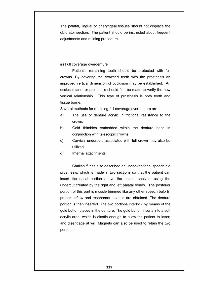
227
The palatal, lingual or pharyngeal tissues should not displace the
obturator section. The patient should be instructed about frequent
adjustments and relining procedure.
iii) Full coverage overdenture
Patient’s remaining teeth should be protected with full
crowns. By covering the crowned teeth with the prosthesis an
improved vertical dimension of occlusion may be established. An
occlusal splint or prosthesis should first be made to verify the new
vertical relationship. This type of prosthesis is both tooth and
tissue borne.
Several methods for retaining full coverage overdenture are
a) The use of denture acrylic in frictional resistance to the
crown.
b) Gold thimbles embedded within the denture base in
conjunction with telescopic crowns.
c) Cervical undercuts associated with full crown may also be
utilized.
d) Internal attachments.
Chalian 29 has also described an unconventional speech aid
prosthesis, which is made in two sections so that the patient can
insert the nasal portion above the palatal shelves, using the
undercut created by the right and left palatal bones. The posterior
portion of this part is muscle trimmed like any other speech bulb till
proper airflow and resonance balance are obtained. The denture
portion is then inserted. The two portions interlock by means of the
gold button placed in the denture. The gold button inserts into a soft
acrylic area, which is elastic enough to allow the patient to insert
and disengage at will. Magnets can also be used to retain the two
portions.

228
Rehabilitation of patients with maxillofacial defects is not merely a
post treatment eventuality. It is a complex interaction of the patient with a
variety of health professionals, the main objective being restoration of
bodily and psychic function to optimum potential and to prevent additional
dysfunction and inconvenience. Rehabilitation involves concern for the
patient as a person, as well as for the patient’s social well being. It implies,
extending to the patient and the family and friends all available resources.
The maxillofacial prosthodontist normally provides appliances and
devices to restore esthetics and functions, to the patient who cannot be
restored to normal appearance or function by means of plastic
reconstruction. The prosthodontist may also be called upon to treat
patients who are at poor surgical risks for extensive plastic surgical
procedures. Rehabilitation of these patients is a challenging task and
should stress upon the psycho-dynamic interactions of health
professionals with the patient and significant persons in the patient’s life
Problems associated with the patient’s needs and special
consideration for prosthesis, potential changes in inter-personal
relationships, identification problems, mutilations, employment, special
work considerations, stress and strain of physical impairment, social
relationships, the face of death, the potential loss of sight, speech and
other important functions; all augur against assuming that the patient can
take, the trauma all-alone.
The most commonly occurring maxillofacial defects are the clefts of
the hard and soft palate. The prosthetic means of correcting these defects
comprises essentially of two forms of appliances i.e. the obturator and the
artificial velum. The literature suggests various types of designs, methods
of fabrication and materials in the fabrication of these prostheses.
This discussion hereby makes an attempt to throw light on
prosthetic philosophies and procedures in rehabilitating these patients.
Prosthodontic principles form the basis of all procedures albeit with
a few modifications to suit the needs of the situation. The partially
dentulous patient with a palatal defect is treated with a definitive
prosthesis, which is basically a removable partial denture with an obturator
extension. The design philosophy for the partially dentate patient is based
on the works of Aramany 7,8 and Desjardins 40. The tripodal design is

229
favoured over the linear design, with multiple support regions to transfer
the stresses. The presence of a large defect with little support gives rise to
a greater lateral torquing force. Desjardins suggested the use of a retainer
as close to the defect and as far from it as possible. Taylor 135 has modified
this slightly and has advocated that one retainer should be located as
close to the defect but the second retainer should be as far apart from the
first retainer as possible. Aramany has advocated the use of bilateral
retention but Taylor has suggested using large guide planes to
compensate for the lack of cross arch stabilization. The use of bonded
metal or composite contours or crowns can be fabricated and used
effectively if the contours of the natural dentition are not ideally suited for
these guide planes.
In implant supported obturator prosthesis the following outlines as
suggested by Beumer & Curtis17 should be considered. If the entire
premaxilla remains – the number of implants, distribution and design of
retention bar follows conventional prosthodontic principles.If only 2
implants are placed , one each in canine region – a Hader bar design is
used. If 4 or more implants are used. The support is provided posteriorly
by the residual denture bearing surfaces and anteriorly by the implants.
The attachments connected to the distal portion of the bar allow for the
compression of the distal extension area of the prosthesis into the denture
bearing area without applying excess torquing force onto the implants. If 6
or more implants are used and the antero-posterior spread is greater than
2 cm, the overlay obturator prosthesis can be designed so that occlusal
forces are primarily supported by the implants.
Retention of the prosthesis is vital. Ambroise Pare 28 is considered
to be the first to design an obturator. He used a sponge and a turnbuckle
to obtain mechanical retention. Pierre Fauchard 28 also used winged
turnbuckles. In the dentate patient interdental wiring retains the surgical
obturator while circumalveolar or circumzygomatic wiring, bone screws and
sutures are used in the edentulous condition. In the definitive prosthesis in
partially dentate patient casted retainers need to be used while wrought
wire clasps can be used for the interim prosthesis. Chalian 29, Roberts also
mention the use of intermaxillary or George Washington springs and
swivels. Swing lock design with multiple retentive bar clasps can be used
as described by Javid & Dadmanesh63 or in combination with conventional

230
retainers as described by Marunick80. Innovative means like utilizing the
anatomical undercuts by inflatable balloons has been advocated by Payne
& Welton105 and Coffey33. Brown 23 has advocated the buttressing the
lateral border of the obturator against the skin graft and placing it as high
and as far away as possible from the rotational path and utilizing the
undercut created at the junction of the split skin graft and the mucosa
junction.
In a young cleft palate patient where an interim obturator or
speech-aid prosthesis is required, retention can be gained by soldering a
buccal tube (lugs) or an orthodontic bracket to a band or stainless steel
crown under which an extended arm wrought wire clasp is given. This is
required, as deciduous teeth do not offer enough undercuts and clinical
height to use conventional clasps.
Magnets (samarium cobalt) can be effectively used to provide
retention for an obturator segment to the main denture in a sectional
prosthesis as described by Boucher21 and Matsumura et al 83.
Use of an overlay (telescopic) crown or a thimble can also be used
for overdentures. Also a Baker/Anderson bar with a clip attachment is used
for a snap-on prosthesis29. Use of precision and semi-precision
attachments provide an aesthetic means of retention and no reciprocal arm
is required. Resilient ERA attachment have been favoured especially in
implant retained prosthesis but care should be taken for controlling the axis
of rotation.17
The weight of the prosthesis is crucial and hence bulky areas
should be hollowed out to reduce weight so that teeth and supporting
tissues are not stressed unnecessarily especially when the obturator
prosthesis is suspended without bony or posterior tooth support on the
defect side. Wu and Schaaf153 have found that hollowing the obturator
prosthesis reduces weight by 7-33% depending on the size of the defect.
The superior surface can either be left open or closed. Clinicians who
prefer closed top state that if the obturators are left open, nasal secretions
accumulate leading to bad odour and added weight29.
Advantages of leaving the top open are that the weight of the
obturator is further reduced as there is no lid, it is easier to adjust and
speech is better. The effect of length of extension into the defect and top
configuration (open/closed) was studied by Aramany and Drane (1972)
and Oral96; and they found that the speech quality using the limited
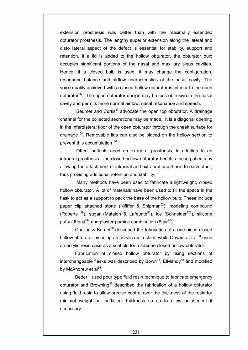
231
extension prosthesis was better than with the maximally extended
obturator prosthesis. The lengthy superior extension along the lateral and
disto lateral aspect of the defect is essential for stability, support and
retention. If a lid is added to the hollow obturator, the obturator bulb
occupies significant portions of the nasal and maxillary sinus cavities.
Hence, if a closed bulb is used, it may change the configuration,
resonance balance and airflow characteristics of the nasal cavity. The
voice quality achieved with a closed hollow obturator is inferior to the open
obturator96. The open obturator design may be less obtrusive in the nasal
cavity and permits more normal airflow, nasal resonance and speech.
Beumer and Curtis17 advocate the open top obturator. A drainage
channel for the collected secretions may be made. It is a diagonal opening
in the inferolateral floor of the open obturator through the cheek surface for
drainage154. Removable lids can also be placed on the hollow section to
prevent this accumulation106
Often, patients need an extraoral prosthesis, in addition to an
intraoral prosthesis. The closed hollow obturator benefits these patients by
allowing the attachment of intraoral and extraoral prosthesis to each other,
thus providing additional retention and stability.
Many methods have been used to fabricate a lightweight, closed
hollow obturator. A lot of materials have been used to fill the space in the
flask to act as a support to pack the base of the hollow bulb. These include
paper clip attached stone (Nififfer & Shipman92), modeling compound
(Roberts 29), sugar (Matalon & Lafeunte82), ice (Schneider122), silicone
putty (Jhanji64) and plaster-pumice combination (Blair20).
Chalian & Barnet30 described the fabrication of a one-piece closed
hollow obturator by using an acrylic resin shim, while Ohyama et al93 used
an acrylic resin case as a scaffold for a silicone closed hollow obturator.
Fabrication of closed hollow obturator by using sections of
interchangeable flasks was described by Bown24, ElMahdy45 and modified
by McAndrew et al86.
Beder11 used pour type fluid resin technique to fabricate emergency
obturator and Browning26 described the fabrication of a hollow obturator
using fluid resin to allow precise control over the thickness of the resin for
minimal weight but sufficient thickness so as to allow adjustment if
necessary.

232
The use of silicone as an obturator bulb has been described by a
lot of authors. It offers the advantages or flexibility, which allows more
engagement of undercut and is less damaging to the frail tissues in the
defect region. However, it is subject to fungal infiltration and needs to be
changed frequently. Boucher21 used silastic bulb attached to the main
prosthesis by magnets while Hahn54 used an acrylic insert in the denture to
attach the silicone bulb. Wood & Carl151 used flexible impression trays and
fabricated silicone obturator. Taicher et al133 used polydimethyl siloxane
obturators in patients with severe trismus and unyielding tissue.
Vacuforming machines can be used to fabricate immediate surgical
obturators.43,70
The use of visible light cured resin has been described. It is
definitely the material for the future as it is very easy to use, it reduces the
laboratory steps, it is dimensionally accurate, even more than heat-cured
resin due to the absence of the monomer content.
Soft Palate obturation has been done in three different ways. The fixed
horizontal obturator has been found to be the most effective while the
meatus obturator is best for edentulous patients with total soft palate
defects. The hinge type pharyngeal obturators do not find much favour due
to the difficult fabrication, greater weight and reduced efficiency.
Gibbons and Bloomer first described palatal Lift prosthesis. Its use still
remains controversial. The literature has sufficient number of protagonists
to indicate that the palatal lift prosthesis is capable of offering benefits. In
fact, its use has also been associated with the stimulation of muscle
activity leading to reducing the incompetency leading to a situation, where
it is not required. With the increased availability of the advanced
diagnostic aids, the procedure even though complicated can be carried out
for the benefit of the patient.
The treatment of Cleft lip and palate patients has reached a stage where
the team approach of all specialties has been universally acknowledged.
The use of presurgical orthopedics since its introduction by McNeil in 1950
is gaining favour due to highly esthetic results and ease of surgical
technique.
The advances in surgical technique with vascularized bone containing
flaps, the acceptability of implants on radiated sites, use of accessory sites
like zygoma for implants have revolutionized the reconstruction and

233
rehabilitation. Its widespread use will provide the quality of life for the
patients that we as maxillofacial prosthodontics strive to achieve.
Rehabilitation of patients with maxillofacial defects has always remained an
enigma for the prosthodontist due to the unpredictable nature of the defects and
uncertainty of recurrence.

234
An attempt has been made to review to prosthetic aspects of the
rehabilitation of the patients with palato- maxillary defects with a strong
emphasis on the understanding of the anatomical and physiological
considerations and the psychosocial well being of the patient.
The rehabilitation is not merely by closing a defect with prosthesis but goes
much beyond that. To reach these goals a multidisciplinary approach needs to
be adopted
Although, the advances in materials have been remarkable, the
subspecialty has not reached its full potential. There is thus, a need of for
prosthodontists to take interest and involve them in this endeavour to
rehabilitate these patients to feel and function normally and integrate back in
society with confidence.
Bibliography
1. Ackerman A.J. Prosthetic management of oral and facial defects following
cancer surgery. J Prosthet Dent: 1955; 5:413-432
2. Adisman KI. Removable partial dentures for jaw defects of maxilla and
mandible. DCNA 1962:849-870
3. Adisman KI, Laney WR; Minimum acceptable laboratory procedures for
maxillofacial prosthesis. J Prosthet Dent: 1972; 27:91-93
4. Ampil JP, Ellinger CW, Rahn AO. A temporary prosthesis for an edentulous
patient following maxillary resection. J Prosthet Dent: 1967; 17:88-91

235
5. ApplemanRM; Prosthetic repair of defects of maxilla resulting from surgery.
J Prosthet Dent: 1951; 1:424-438
6. Aram A, SubtelnyJD; Velopharyngeal function and cleft palate prosthesis. J
Prosthet Dent: 1959; 9:149
7. Aramany MA; Basic principles of obturator design for partially edentulous
patients. Part I: Classification. J Prosthet Dent: 1978; 40:554-557
8. Aramany MA; Basic principles of obturator design for partially edentulous
patients. Part II:Design principles. J Prosthet Dent: 1978; 40:656-662
9. Bailey LW, Edwards D; Psychological considerations in maxillofacial
prosthetics. J Prosthet Dent1975; 34:533-538
10. Bardach J, Morris HL; Multidisciplinary management of Cleft lip and palate.
1990- WB Saunders. 366-377
11. Beder OE; Emergency temporary obturators. J Prosthet Dent 1968; 20:
172-175
12. Beery QC, Aramany MA, Katzenberg B; Oral endoscopy in the
prosthodontic management of the soft palate defect. J Prosthet Dent: 1985;
54:241-244
13. Bell WT, Chalian VA, Moore K; Polydimethyl silicone materials in
maxillofacial prosthetics: Evaluation and comparison of physical properties.
J Prosthet Dent: 1985; 54:404-410
14. Benington IC, Clifford T; an injection impression technique for palatal
defects. J Prosthet Dent: 1982; 47:414-418; Light Cured obturators. J
Prosthet Dent:1989;62:322-5
15. Berkowitz S. Cleft Lip and Palate: Perspectives in management. With an
introduction to other craniofacial anomalies. Volume I; 189-194
16. Berkowitz S. Cleft Lip and Palate: Perspectives in management. With an
introduction to other craniofacial anomalies. Volume II
17. Beumer J III, Curtis TA, Marunick MT; Maxillofacial Rehabilitation:
Prosthodontic and surgical considerations; Ishiyaku-America Publishers; 2nd
Edition; 1-22,225-370,387-399
18. Birnbach S, Barnhard B; Direct conversion of a solid obturator to a hollow
prosthesis. J Prosthet Dent: 1989; 62:58-60
19. Black WB: surgical obturation using a gated prosthesis. J Prosthet Dent:
1992; 68:339-342
20. Blair FM,Hunter NR; The hollow box maxillary obturator. BDJ 1998, Vol
184,No 10,484-487

236
21. Boucher LJ. Prosthetic restoration of maxilla and associated structures. J
Prosthet Dent: 1966; 16: 154-168
22. Brosky ME,Lee C,Bartlett S, Los; Fabrication of a radiation bolus
prosthesis for the maxillectomy patient. J Prosthet Dent: 2000:83:119-121
23. Brown KE. Peripheral considerations in improving obturator retention. J
Prosthet Dent: 1968; 20: 176-181
24. Brown KE. Fabrication of hollow bulb obturator. J Prosthet Dent: 1969; 21:
97-103
25. Brown KE. Clinical considerations for improving obturator treatment. J
Prosthet Dent: 1970; 24: 461-466
26. Browning JD, Kinderknecht J; Fabrication of hollow obturator with fluid
resin. J Prosthet Dent: 1984; 52: 891-895
27. Buckner H. construction of denture with hollow obturator, lid and soft acrylic
lining. J Prosthet Dent: 1974; 31: 95-99
28. Bulbulian AH; Maxillofacial Prosthetics: Evolution and practical application
in patient rehabilitation. J Prosthet Dent 1965; 15:554-569
29. ChalianVA, Drane JB, Standish SM; Maxillofacial Prosthetics-
Multidisciplinary Practice; Williams & Wilkins1971; 1-13,89-121; 133-
158,358-424
30. Chalian VA, Barnett BO. A new technique for constructing a one piece
hollow obturator after partial maxillectomy. J Prosthet Dent: 1972; 28: 448-
453
31. Chambers MS,Lemon JC, Martin JW; Obturation of the partial soft palate
defect. J Prosthet Dent: 2004; 91:75-79
32. Chierici G, Lawson L; Clinical speech considerations in prosthodontics:
perspectives of the prosthodontist and speech pathologist. J Prosthet Dent:
1973; 29-39
33. Coffey KW; Obturation of congenital or acquired intraoral anatomic defects.
J Prosthet Dent: 1984; 52:559-560
34. Cotert HS,Cura C; Modified flasking technique for processing a maxillary
resection obturator with continuous pressure injection. J Prosthet Dent:
2001; 86:438-440
35. Curtis Ta, Taylor RC, Rositano SA; Physical problems in obtaining records
of the maxillofacial patient. J Prosthet Dent: 1975; 34:539-554
36. DaBreo El,Ghalichebaf M; Provisional restoration for a patient with cleft lip
and palate: A clinical report. J Prosthet Dent: 1990; 63:119-121

237
37. DaBreo EL; light cured interim obturator prosthesis. A clinical report. J
Prosthet Dent: 1990; 63:371-373
38. DaBreo EL; Dimensional change in maxillary prosthetic obturators. J
Prosthet Dent: 1991; 66:669-673
39. Dalston RM; Prosthodontic management of cleft palate patient: a speech
pathologist’s view. J Prosthet Dent: 1977; 37:190-195
40. Desjardins RP; Obturator prosthesis design for acquired maxillary defects.
J Prosthet Dent: 1978; 39: 424-435
41. DexterWS, Jacob RF; Prosthetic rehabilitation after maxillectomy and
temporalis flap reconstruction. A clinical report
42. Didier M, Laccoureye O,VignonM; New surgical obturator prosthesis for
hemimaxillectomy patients. J Prosthet Dent: 1993; 69:520-523
43. Disantis WS; Quick technique for construction of surgical obturator. J
Prosthet Dent: 1985; 53:128-1129
44. Donald ET; Speech considerations in cleft palate patients. J Prosthet Dent:
1951; 1:629-637
45. El Mahdy AS. Processing a hollow obturator. J Prosthet Dent: 1969;
22:682-686
46. Esposito SJ, Mitsumoto H, Shanks M; Use of palatal lift and palatal
augmentation prosthesis to improve dysarthria in patients with Amyotrophic
lateral sclerosis: A case series. J Prosthet Dent: 2000; 83:90-98
47. Gardner LK, Parr GR, Rahn AO; Combination nasal support breathing
flange with hollow obturator prosthesis: A clinical report. J Prosthet Dent:
1990; 63:497-501
48. Gardner LK, Parr GR, Rahn AO; Simplified technique for the fabrication of
a hollow prosthesis using vinyl polysiloxane. J Prosthet Dent: 1991; 66:60-
62
49. Gay WD, King GE; Applying basic prosthodontics principles in dentulous
maxillectomy patients. J Prosthet Dent: 1980; 43:433-435
50. Gaylord J;Cleft palate restoration: An interpretation of the Fitz Gibbon
technique. J Prosthet Dent: 1951; 1:268-286
51. GibbonsP, Bloomer HH; A supportive type prosthetic speech aid. J
Prosthet Dent: 1958; 8: 363-369
52. Groetsema WR; an overview of the maxillofacial prosthesis as a speech
rehabilitation aid. J Prosthet Dent: 1987; 57:204-208
53. Habib BH,Driscoll CF;Fabrication of a closed hollow obturator. J Prosthet
Dent: 2004; 91:383-385

238
54. Hahn GW. A comfortable silicone bulb obturator with or without dentures. J
Prosthet Dent: 1972; 28: 313-317
55. Hammond; Dental care of edentulous patients after resection of maxilla.
BDJ 1966; 120:591
56. Huryn JM, Piro JD; The maxillary immediate surgical obturator prosthesis. J
Prosthet Dent: 1989; 61:343-347
57. Immekus JE, Aramany MA; A fixed- removable partial denture for cleft
palate patients. J Prosthet Dent: 1975; 34:286-291
58. Ismail JY, Zaki HS; Osseointegration in Maxillofacial prosthetics. DCNA
April 1990,Vol34, No.2, 327-341
59. Jacob RF, Martin JW, King GE; Modification of surgical obturators to
interim prostheses. J Prosthet Dent: 1985; 54:93-95
60. Jacob RF, King G; Indirect retainers in soft palate obturator design. J
Prosthet Dent: 1990; 63:311-5
61. Jacob RF,Yen TW; Processed record bases for the edentulous
maxillofacial patient. J Prosthet Dent: 1991; 65:680-685
62. Jacob RF; Duplication of interim speech aid for definitive impression tray
fabrication. J Prosthet Dent: 1992; 68:561-562
63. JavidNS, Dadmanesh J; Obturator design for hemi maxillectomy patients. J
Prosthet Dent: 1976; 36:77-81
64. Jhanji A,Stevens ST; Fabrication of one piece hollow obturators. J Prosthet
Dent:1991;66:136-138
65. Kaplan P; Palatal contour guide for positioning retentive framework for
obturation for a hemi maxillectomy patient. J Prosthet Dent: 1992; 62:715-
716
66. Karnell MP, Rosenstein H, Fine L; Nasal videoendoscopy in prosthetic
management of palatopharyngeal dysfunction J Prosthet Dent: 1987;
58:479-484
67. King GE, Martin JW; Cast circumferential and wire clasps for obturator
retention. J Prosthet Dent: 1983; 49:799-802
68. Khan Z;Soft palate obturator prosthesis made in visible light cure resin. J
Prosthet Dent::1989;62:671-673
69. Kloeffler GD; A report on maxillary orthopedics in cleft palate treatment. J
Prosthet Dent:: 1970;23:227-231
70. Kouyoumdjian JH,Chalian VA; An interim obturator prosthesis with
duplicated teeth and palate. J Prosthet Dent: 1984; 52:560-562
71. Lang; Modification of palatal lift speech aid. J Prosthet Dent: 1967; 17: 216

239
72. Lavelle WE, Hardy JC; Palatal lift prosthesis for treatment of
palatopharyngeal incompetence. J Prosthet Dent: 1979; 42:308-315
73. Lazzari JB; A prosthetic closure of a traumatic palatal perforation. J
Prosthet Dent: 1952; 2:831-833
74. LeonardRJ; Computerized design of speech prosthesis. J Prosthet Dent:
1991; 66:224-230
75. Light J; Functional assessment testing for maxillofacial prosthetics. J
Prosthet Dent: 1997; 77:388-93
76. Lontz JF; State of the art materials used for maxillofacial prosthetic
reconstruction. DCNA April 1990;vol 34,no.2, 307-325
77. Mac Carthy D, Murphy N; Replacement of an obturator section of an
existing two-piece implant retained edentulous obturator. J Prosthet Dent:
2000; 83:652-655
78. Mahanna GK,Berkellman DF, Marshal JA,Sullivan M; Obturator prosthesis
after cancer surgery. An approach to speech outcome analysis. J Prosthet
Dent: 1998; 79:310-316
79. Marshall RC,Jones ; effects of palatal lift prosthesis upon speech
intelligibility of a dysarthric patient. J Prosthet Dent: 1971; 25:327-333
80. Marunick M; Hybrid gate design frameworks for the rehabilitation of the
maxillectomy patient. J Prosthet Dent: 2004; 91:315-318
81. Masumi S, Miyake S, Kido, Toyoda; Use of a sectional prosthesis following
partial maxillary resection. A clinical report. J Prosthet Dent: 1990; 64:401-
403
82. Matalon V, La Feunte H; A simplified method for making a hollow obturator.
J Prosthet Dent: 1976; 36: 580-582
83. Matsumura H,Kawasaki K; Magnetically connected removable sectional
denture for a maxillary defect with severe undercut: A clinical report. J
Prosthet Dent: 2000; 84:22-26
84. Mauk EH; Cleft palate prosthesis: American textbook on prosthodontics.
Pg-863-912
85. Mazaheri M, Mazaheri EH; Prosthodontic aspect of palatal elevation and
palatopharyngeal stimulation. J Prosthet Dent: 1976; 35: 319
86. McAndrew KS, Rothenberger S, Minsely GE; An innovative investment
method for the fabrication of closed hollow obturator prosthesis. J Prosthet
Dent: 1998; 80:129-132
87. Miglani DC, DraneJ; Maxillofacial prosthesis and its role as a healing act. J
Prosthet Dent: 1959; 9:159-168
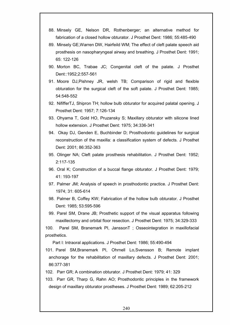
240
88. Minsely GE, Nelson DR, Rothenberger; an alternative method for
fabrication of a closed hollow obturator. J Prosthet Dent: 1986; 55:485-490
89. Minsely GE,Warren DW, Hairfeild WM; The effect of cleft palate speech aid
prosthesis on nasopharyngeal airway and breathing. J Prosthet Dent: 1991;
65: 122-126
90. Morton BC, Trabae JC; Congenital cleft of the palate. J Prosthet
Dent::1952;2:557-561
91. Moore DJ,Pishney JR, welsh TB; Comparison of rigid and flexible
obturation for the surgical cleft of the soft palate. J Prosthet Dent: 1985;
54:548-552
92. NififferTJ, Shipron TH; hollow bulb obturator for acquired palatal opening. J
Prosthet Dent: 1957; 7:126-134
93. Ohyama T, Gold HO, Pruzansky S; Maxillary obturator with silicone lined
hollow extension. J Prosthet Dent: 1975; 34:336-341
94. Okay DJ, Genden E, Buchbinder D; Prosthodontic guidelines for surgical
reconstruction of the maxilla: a classification system of defects. J Prosthet
Dent: 2001; 86:352-363
95. Olinger NA; Cleft palate prosthesis rehabilitation. J Prosthet Dent: 1952;
2:117-135
96. Oral K; Construction of a buccal flange obturator. J Prosthet Dent: 1979;
41: 193-197
97. Palmer JM; Analysis of speech in prosthodontic practice. J Prosthet Dent:
1974; 31: 605-614
98. Palmer B, Coffey KW; Fabrication of the hollow bulb obturator. J Prosthet
Dent: 1985; 53:595-596
99. Parel SM, Drane JB; Prosthetic support of the visual apparatus following
maxillectomy and orbital floor resection. J Prosthet Dent: 1975; 34:329-333
100. Parel SM, Branemark PI, JanssonT ; Osseointegration in maxillofacial
prosthetics.
Part I: Intraoral applications. J Prosthet Dent: 1986; 55:490-494
101. Parel SM,Branemark PI, Ohrnell Lo,Svensson B; Remote implant
anchorage for the rehabilitation of maxillary defects. J Prosthet Dent: 2001;
86:377-381
102. Parr GR; A combination obturator. J Prosthet Dent: 1979; 41: 329
103. Parr GR, Tharp G, Rahn AO; Prosthodontic principles in the framework
design of maxillary obturator prostheses. J Prosthet Dent: 1989; 62:205-212
241
104. Parr GR, GardnerLK; The evolution of the obturator framework design. J
Prosthet Dent: 2003; 89:608-610
105. Payne AGL, Welton WG. An inflatable obturator for use following
maxillectomy. J Prosthet Dent: 1965; 15:759-763
106. Phansokol P, Martin JW; Hollow obturator with removable lid. J Prosthet
Dent: 1985; 54: 98-100
107. Philip C; orthodontic management of congenital cleft palate patient. DCNA
April 1990,Vol34, No.2, 343-359
108. Pigno MA, Funk BS; Augmentation of obturator retention by extension into
the nasal aperture. J Prosthet Dent: 2001;85:349-351
109. Pigno MA;Conventional prosthetic rehabilitation after free flap
reconstruction of a maxillectomy defect: A clinical report. J Prosthet Dent: 2001;
86:578-581
110. Polyzois GL; Light cured combination obturator prosthesis. J Prosthet Dent:
1992; 68:345-347
111. Pomerantz JM, Zimmerman DE; The use of non-parallel canine abutments
for a tissue bar overdenture obturator. J Prosthet Dent: 1982; 47:194-197
112. Rahn AO, Boucher LJ; Maxillofacial Prosthodontics: Principles & Concepts;
WB Saunders1970; 1-17,83-112,188-227
113. Rahn AO,Goldman BM,Parr GR; Prosthodontic principles in surgical
planning for maxillary and mandibular resection patients. J Prosthet Dent: 1979;
42:429-433
114. Ramsey WO; Terminology applicable to palatal lift prosthesis. J Prosthet
Dent: 1983; 49:680-684
115. Reisberg DJ, Smith BE; Aerodynamic assessment of prosthetic speech
aids. J Prosthet Dent: 1985; 54:686-690
116. Riley C; Treatment obturator for the edentulous patients. J Prosthet Dent:
1970; 24:312-319
117. RiloB, Martinez-InsuaA, Santana; titanium and visible light polymerized
resin obturator. J Prosthet Dent: 2002; 87:407-409
118. Robinson JE. Prosthetic treatment after surgical removal of maxilla and
floor of orbit. J Prosthet Dent: 1963; 13:178-184
119. Roumanous ED, Nishimura RD, Davis, Beumer J III; Clinical evaluation of
implants retaining edentulous maxillary obturator prostheses. J Prosthet Dent:
1997; 77:184-190
120. Sato Y, Sato M,Yoshida; Palatal cleft prosthesis for edentulous patients. J
Prosthet Dent: 1987; 58: 206-210

242
121. Schmaman J,Carr L; A foam impression technique for maxillary defects. J
Prosthet Dent: 1992; 68:342-344
122. Schneider A ; Method of fabricating a hollow obturator. J Prosthet Dent:
1978; 40 : 351
123. SchwartzmanB,Caputo A, Beumer J; Occlusal force transfer by removable
partial denture designs for a radical maxillectomy. J Prosthet Dent: 1985;
54:397-403
124. Sharry JJ; Meatus obturator in particular and pharyngeal impressions in
general. J Prosthet Dent: 1958; 8:893
125. Sharry JJ; Complete Denture Prosthodontics; McGraw Hill Book
Company;343-356
126. Shifman A; A technique for the fabrication of an open obturator. J Prosthet
Dent 1983; 50:384-385
127. Shifman A; Clinical applications of visible light cured resin in maxillofacial
prosthetics. Part I Denture base and reline material. J Prosthet Dent: 1990;
64:578-582
128. Shifman A; Clinical applications of visible light cured resin in maxillofacial
prosthetics. Part II Tray material. J Prosthet Dent: 1990; 64:695-699
129. Shifman A,Finkelstein Y,Nachmani, Ophir; Speech aid prosthesis for
neurogenic velopharyngeal incompetence. J Prosthet Dent: 2000; 83:99-106
130. Shimodaira K, Yoshida H, Funakabo T; Obturator prosthesis conforming to
the movement of the soft palate: A clinical report. J Prosthet Dent: 1994;
71:547-551
131. Sigurgeissdoiter E,Minsely GE, Rothenberger SL; Incorporation of an ERA
attachment for obturator framework. J Prosthet Dent: 2002; 87:477-480
132. Spratley MH, Cheney HJ, Murdoch BE; A different design of palatal lift
appliance. Review and case reports. Aust Dent J 1988; 33:491-495
133. Taicher S, Rosen AG, Arbree NS, Bergen SF; A technique for fabrication of
polydimethylsiloxane acrylic resin obturator. J Prosthet Dent: 1983; 50: 65-68
134. Tapia G, Casey D, Schaaf NG; Conversion of an interim into a definitive
speech aid: a predictable approach. J Prosthet Dent: 2002; 87:106-109
135. Taylor TD; Clinical maxillofacial Prosthodontics; Quintessence 2000; 1-
15,85-155
136. Taylor TD, desjardins RP; Construction of the meatus type obturator: Its
advantages and disadvantages. J Prosthet Dent: 1983; 49:80-84

243
137. Tobey EA, Lincks J; Acoustic analyses of speech changes after
maxillectomy and prosthodontic management. J Prosthet Dent: 1989; 62:449-
455
138. Toremalm NG. A disposable obturator for maxillary defects. J Prosthet
Dent: 1973; 29: 94
139. Torn DB; Speech and cleft palate: Partial denture prosthesis. J Prosthet
Dent: 1952; 2:412-417
140. Turner GE, Williams WN, Fluoroscopy and nasoendoscopy in designing
palatal lift prosthesis. J Prosthet Dent: 1991; 66:63-71
141. Vojvodic D, Jerolimov V, CelebicA. Prosthetic rehabilitation of a cleft palate
patient: a clinical report. J Prosthet Dent: 1996; 76:230-232
142. Walter JD; Palatopharyngeal activity in cleft palate subjects. J Prosthet
Dent: 1990; 63:187-192
143. Wang RR;Sectional prosthesis for total maxillectomy patients: A clinical
report. J Prosthet Dent: 1997; 78:241-244
144. Wang RR, Hirsch RF; Refining hollow obturator base using light activated
resin. J Prosthet Dent: 1997; 78:327-329
145. Wang RR; Thermoplastic resin used to modify an alveolar orthopedic
prosthesis in-patient with cleft lip before cheiloplasty: a clinical report. J
Prosthet Dent: 1998; 79:613-6
146. Warren DW; Physiologic approach to cleft palate prosthesis. J Prosthet
Dent: 1965; 15: 770-778
147. Watson RM, Gray BJ; assessing effective obturation. J Prosthet Dent:
1985; 54:88-93
148. Williams DR; An impression technique following hard palate repair using
tongue grafts. J Prosthet Dent: 1991; 65:424-427
149. Witt PD, Marsh JL, Grames LM,Gay DW; Management of hypo dynamic
velopharynx. Cleft Palate- Craniofacial Journal-1995, 32,179-186
150. Wolfaardt JF, Wilson FB, Rochet A,, Mc Phee L: An appliance based
approach to the management of palatopharyngeal incompetency: a clinical pilot
project. J Prosthet Dent. 1993 Feb; 69: 186-95.
151. Wood RH, Carl W; Hollow silicone obturator for patients after total
maxillectomy. J Prosthet Dent: 1977; 38: 643-651
152. Worley Jl, Kniejsky ME; A method of controlling the thickness of hollow
obturator prosthesis. J Prosthet Dent 1983,50:227-229
153. Wu Y, Schaaf N; Comparison of weight reduction in different designs of
solid and hollow obturator prostheses. J Prosthet Dent: 1989; 62:214-217

244
154. Zaki HS; Modified bypass in the maxillary hollow bulb obturator. J
Prosthet Dent: 1980; 43: 320- 321
155. Zarb GA. Maxillary resection and its prosthetic replacement. J Prosthet
Dent: 1967; 18: 268
156. Ziada HM, Donovan SO; Procedure for reducing the vertical height of a
hollow box interim obturator. J Prosthet Dent: 2000; 83:58
Related Documents