MAXILLARY MAJOR CONNECTORS

Welcome message from author
This document is posted to help you gain knowledge. Please leave a comment to let me know what you think about it! Share it to your friends and learn new things together.
Transcript
MAXILLARY MAJOR
CONNECTORS
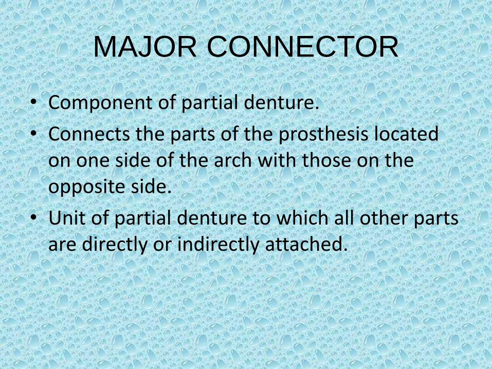
MAJOR CONNECTOR
• Component of partial denture.
• Connects the parts of the prosthesis located on one side of the arch with those on the opposite side.
• Unit of partial denture to which all other parts are directly or indirectly attached.
Functions of major connector
• Unification of the major parts of prosthesis.
• Distribution of applied force throughout the arch to selected teeth and tissue.
• Minimization of torque to the teeth.
• Provides cross arch-stability to help resist displacement by functional stresses.
• Failure of major connector to provide rigidity may be manifest by
traumatic damage to periodontal support of abutment teeth,
injury to residual ridges, or
impingement of underlying tissue.
It is the dentist’s responsibility to ensure that the appropriate design and fabrication of the major connector are accomplished.
LocationThe following guidelines are kept in mind :
• Major connectors should be free of movable tissue.
• Impingement of gingival tissue should be avoided.
• Bony and soft tissue prominences should be avoided during placement and removal.
• Relief should be provided beneath a major connector to prevent its settling into areas of possible interference.
• They should be located and/or relieved to prevent impingement of tissue because the distal extension denture rotates in function.
Characteristics of major connectors
contributing to health and well-being
• Made from an alloy compatible with oral tissue• Is rigid and provides cross-arch stability through
the principle of broad distribution of stress• Does not interfere with and is not irritating to the
tongue• Does not substantially alter the natural contour
of the lingual surface of the mandibular alveolar ridge or of the palatal vault
• Does not impinge on oral tissue when the restoration is placed, removed, or rotates in function

• Covers no more tissue than is absolutely necessary
• Does not contribute to the retention or trapping of food particles
• Has support from other elements of the framework to minimize rotation tendencies in function
• Contributes to the support of the prosthesis
TYPES OF MAXILLARY
MAJOR CONNECTORS
• Single palatal strap
• Combination anterior and posterior palatal strap-type connector
• Palatal plate-type connector
• U-shaped palatal connector
• Single palatal bar
• Anterior-posterior palatal bars
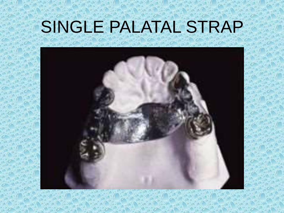
SINGLE PALATAL STRAP
Single Palatal Strap
• Used to connect bilateral tooth-supported prosthesis, even those with short edentulous spaces, particularly when the edentulous areas are located posteriorly.
• It can be made rigid without objectionable bulk and interference with the tongue provided the cast framework material is distributed in three planes.
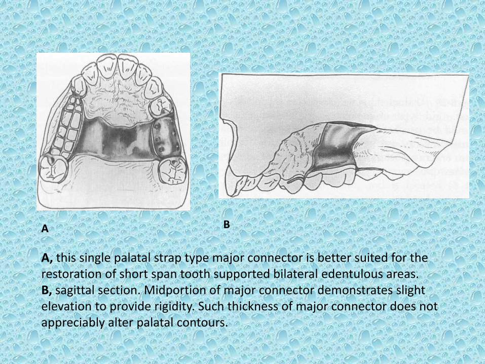
A B
A, this single palatal strap type major connector is better suited for the restoration of short span tooth supported bilateral edentulous areas.B, sagittal section. Midportion of major connector demonstrates slight elevation to provide rigidity. Such thickness of major connector does not appreciably alter palatal contours.

• For reasons of torque and leverage, it should not be used to connect anterior replacements with distal extension bases.
• To be rigid enough to resist torque and provide adequate vertical support and horizontal stabilization, a single palatal strap would have to be objectionably bulky. When placed anteriorly, the bulk would become even more objectionable to the patient interfering with speech.
• More frequently used in class III situations.
COMBINATION ANTERIOR AND
POSTERIOR PALATAL STRAP-
TYPE CONNECTOR
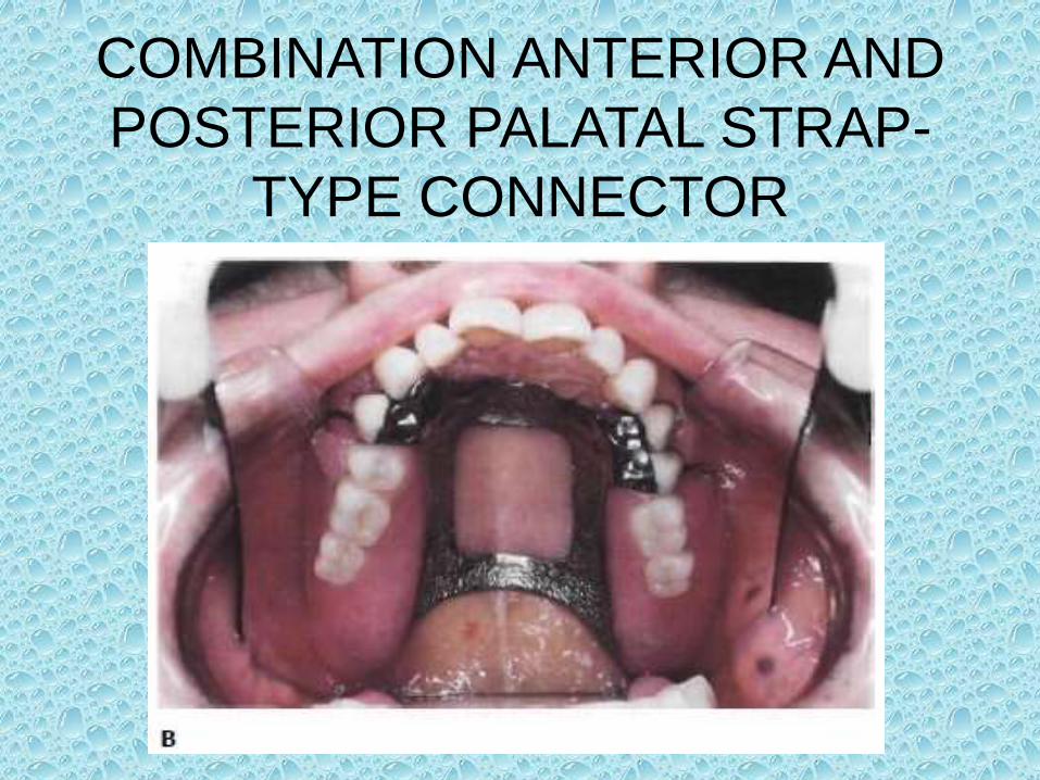
Combination Anterior and Posterior
Palatal Strap-type Connector
• Structurally a rigid major connector.
• May be used in any maxillary partial denture design.
• Posterior palatal strap :
Design- flat and minimum 8 mm wide.
Location- as far posteriorly as possible to avoid interference with tongue but anterior to line of flexure formed by the junction of hard and soft palates.
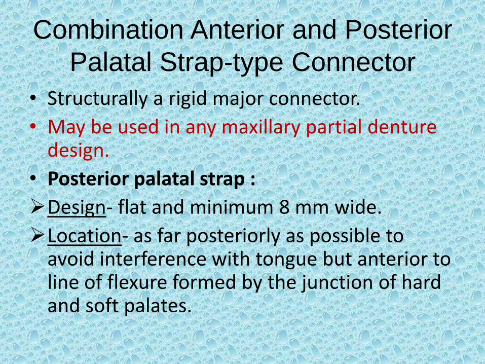
Anterior component is a flat strap located as far posteriorly as possible to avoid rugae coverage and tongue interference.
Anterior border of this strap should be located just posterior to a rugae crest or in the valley between two crests. Posterior strap is
thin, a minimum of 8 mm wide, and Is located as far posteriorly as possible, yet entirely on hard palate. It should be located at right
angles to midline rather than diagonally.
Contraindication: inoperable maxillary torus that extends posteriorly to soft palate (a broad U-shaped major connector is used).
• Anterior connector :
Location: extended anteriorly to support anterior tooth replacements. In this form, a U-shaped connector is made rigid because of the added horizontal strap posteriorly. If a maxillary torque exists, it may be encircled by this type of connector without sacrificing rigidity.

• Strength: lies in the fact that anterior and posterior components are joined together by longitudinal connectors on either side, forming a square or rectangular frame. Each component braces the others against possible torque and flexure.
• Use: used most frequently in classes II and IV.
• All maxillary major connectors should cross the midline at a right angle rather than on a diagonal.
PALATAL PLATE-TYPE
CONNECTOR
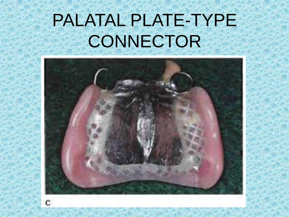
Palatal Plate-type Connector
• Thin, broad, contoured palatal coverage, covering one half or more of the hard palate.
• Anatomic replica palatal castings have uniform thickness and strength because of their corrugated contours.
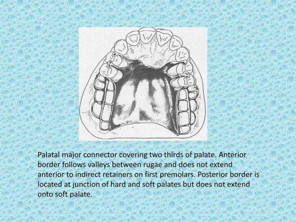
Palatal major connector covering two thirds of palate. Anterior border follows valleys between rugae and does not extend anterior to indirect retainers on first premolars. Posterior border is located at junction of hard and soft palates but does not extend onto soft palate.
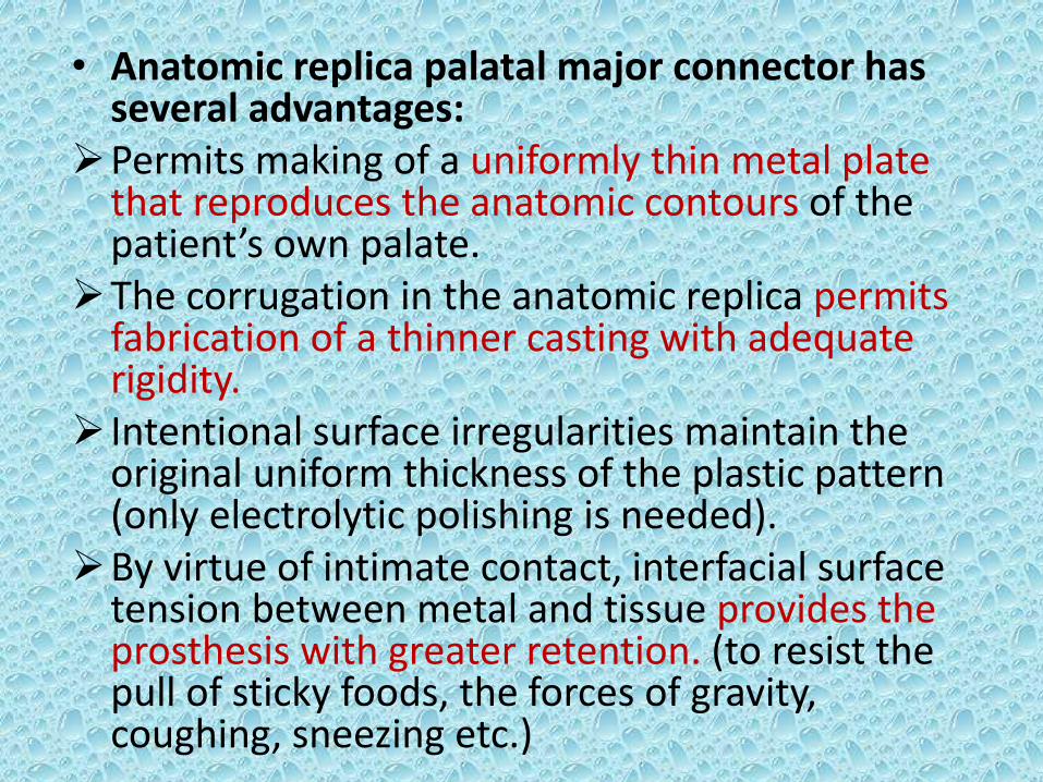
• Anatomic replica palatal major connector has several advantages:
Permits making of a uniformly thin metal plate that reproduces the anatomic contours of the patient’s own palate.
The corrugation in the anatomic replica permits fabrication of a thinner casting with adequate rigidity.
Intentional surface irregularities maintain the original uniform thickness of the plastic pattern (only electrolytic polishing is needed).
By virtue of intimate contact, interfacial surface tension between metal and tissue provides the prosthesis with greater retention. (to resist the pull of sticky foods, the forces of gravity, coughing, sneezing etc.)
Uses of palatal plate-type
connector :
• May be used in one of three ways :
as a plate of varying width that covers the area between two or more edentulous areas,
as a complete or partial cast plate that extends posteriorly to the junction of hard and soft palates (figures A & B), or
in the form of an anterior palatal connector with a provision for extending an acrylic resin denture base posteriorly (figures C & D).
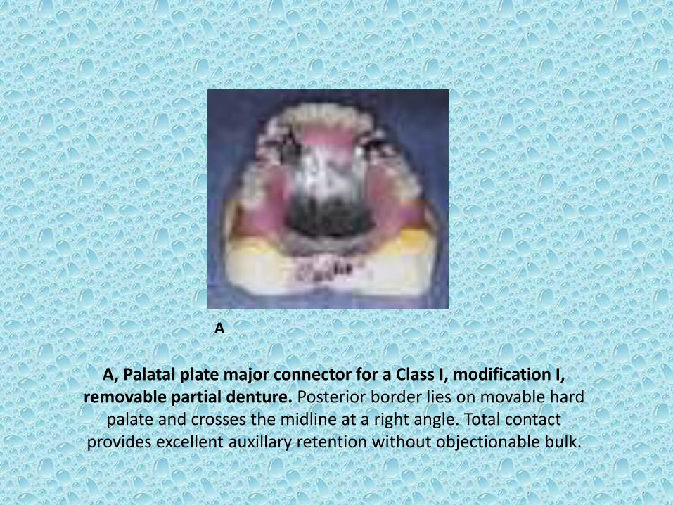
A, Palatal plate major connector for a Class I, modification I, removable partial denture. Posterior border lies on movable hard
palate and crosses the midline at a right angle. Total contact provides excellent auxillary retention without objectionable bulk.
A
Location of palatal Plate-type
Connector :
• Anterior to posterior palatal seal area.
• The maxillary complete denture’s typical posterior palatal seal is not necessary with a maxillary partial denture’s palatal plate because of the accuracy and stability of cast metal.
• When the last remaining abutment tooth on either side of a class I arch is canine or first premolar, complete palatal coverage is strongly advised, especially when the residual ridges have undergone excessive vertical resorption. This may be accomplished in one of two ways :
• Use a complete cast plate extending to junction of hard and soft palates (figure B).
• Use a cast major connector anteriorly, with retention posteriorly, for the attachment of an acrylic-resin denture base to the anatomic landmarks (figures C & D).
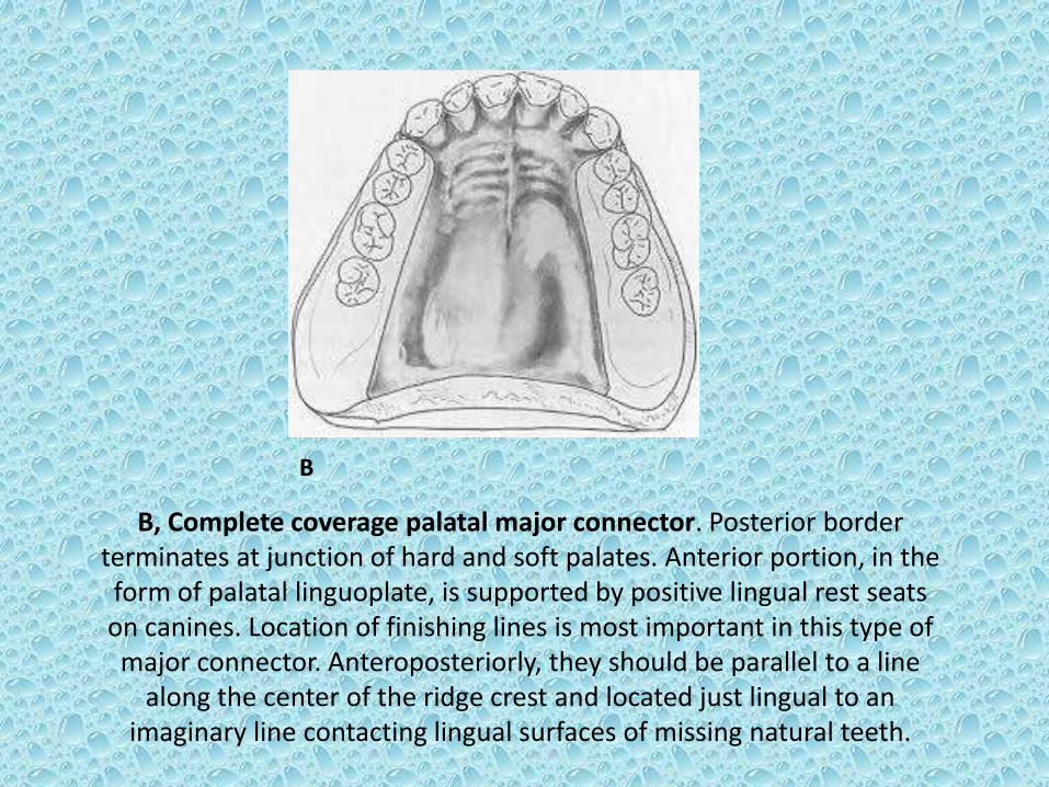
B, Complete coverage palatal major connector. Posterior border terminates at junction of hard and soft palates. Anterior portion, in the form of palatal linguoplate, is supported by positive lingual rest seats on canines. Location of finishing lines is most important in this type of major connector. Anteroposteriorly, they should be parallel to a line
along the center of the ridge crest and located just lingual to an imaginary line contacting lingual surfaces of missing natural teeth.
B
C D
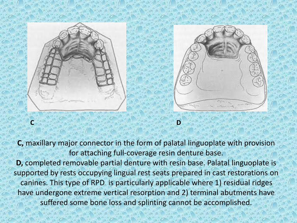
C, maxillary major connector in the form of palatal linguoplate with provision for attaching full-coverage resin denture base.
D, completed removable partial denture with resin base. Palatal linguoplate is supported by rests occupying lingual rest seats prepared in cast restorations on
canines. This type of RPD is particularly applicable where 1) residual ridges have undergone extreme vertical resorption and 2) terminal abutments have
suffered some bone loss and splinting cannot be accomplished.
Related Documents