MAX 1000 User's Manual Manual del Usuario

Welcome message from author
This document is posted to help you gain knowledge. Please leave a comment to let me know what you think about it! Share it to your friends and learn new things together.
Transcript
MAX 1000 User's ManualManual del Usuario
POWER AMPLIFIERAMPLIFICADOR POTENCIADO
ENGLISH.. . . . . . . . . . . . . . . . . . . . . . . . . . . . . . . . . . . . . . . . I
ESPAÑOL.. . . . . . . . . . . . . . . . . . . . . . . . . . . . . . . . . . . . . . . II
MAX 1000English Español
V1.1 05/28/2013
3MAX 1000
English
Phonic preserves the right to improve or alter any information within this document without prior notice.
INTRODUCTION............................................................1
FEATURES..... . . . . . . . . . . . . . . . . . . . . . . . . . . . . . . . . . . . . . . . . . . . . . . . . . . . . . . . . . . . . . .1
INSTALLATION.. . . . . . . . . . . . . . . . . . . . . . . . . . . . . . . . . . . . . . . . . . . . . . . . . . . . . . . . .1
GETTING STARTED............................................................................2
PRODUCT OVERVIEW............................................................3
REAR PANEL...................................................................3
CONNECTIONS.....................................................................3
OPERATION..........................................................................4
FRONT PANEL.........................................................4
REAR PANEL......................................................................4
OPERATING MODES.................................................................5
PROTECTION................................................................................7
AC POWER CONSIDERATIONS..............................................7
INPUT WIRING................................................................7
OUTPUT WIRING......................................................................8
TROUBLESHOOTING....................................................................9
SPECIFICATIONS...................................................................10
DIMENSIONS..... . . . . . . . . . . . . . . . . . . . . . . . . . . . . . . . . . . . . . . . . . . . . . . . . . . . . . . . . .11
CONTENTS
USER'S MANUAL
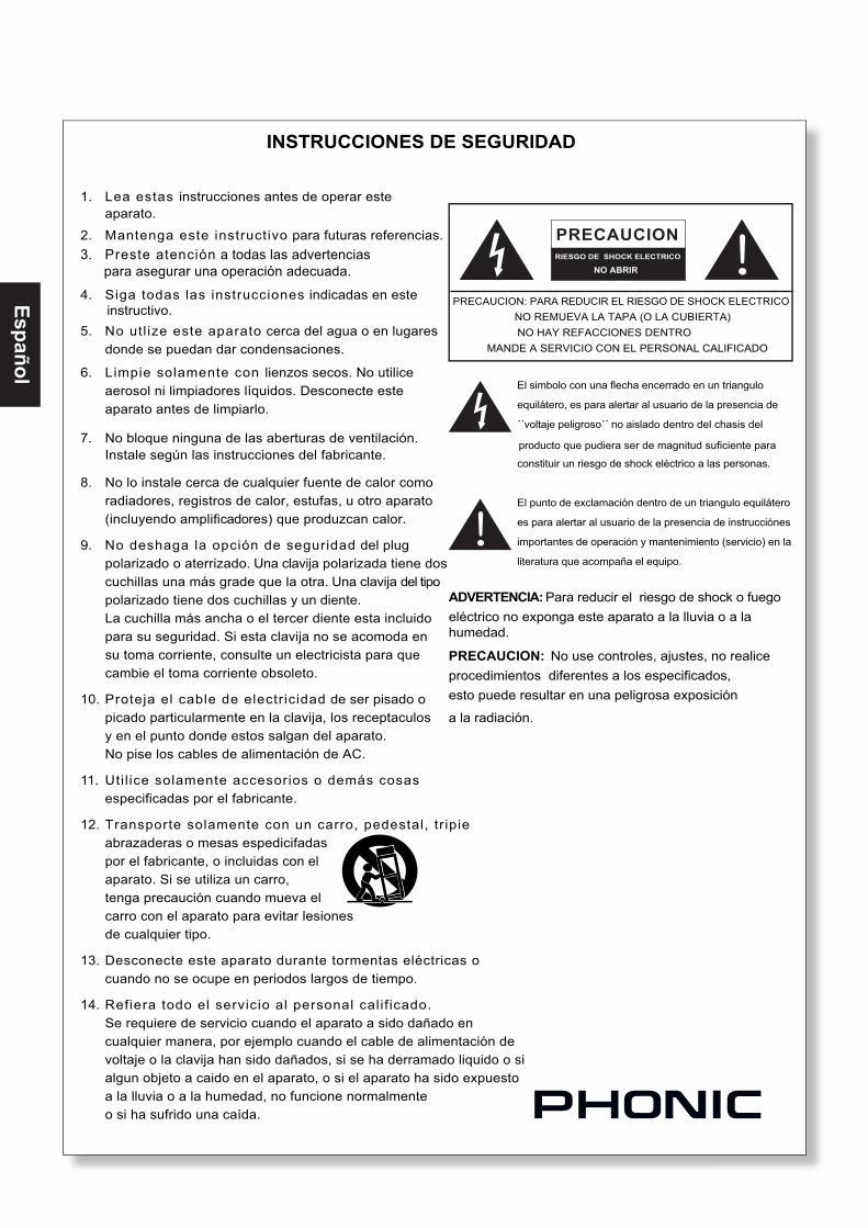
1. Read these instructions before operating this apparatus.
2. Keep these instructions for future reference.
3. Heed all warnings to ensure safe operation.
4. Follow all instructions provided in this document.
5. Do not use this apparatus near water or in locations where condensation may occur.
6. Clean only with dry cloth. Do not use aerosol or liquid cleaners. Unplug this apparatus before cleaning.
7. Do not block any of the ventilation openings. Install in accordance with the manufacturer’s instructions.
8. Do not install near any heat sources such as radiators, heat registers, stoves, or other apparatus (including
.
9. Do not defeat the safety purpose of the polarized or grounding-type plug. A polarized plug has two blades with one wider than the other. A grounding type plug has two blades and a third grounding prong. The wide blade or the third prong is provided for your safety. If the provided plug does not into your outlet, consult an electrician for replacement of the obsolete outlet.
10. Protect the power cord from being walked on or pinched particularly at plug, convenience receptacles, and the point where they exit from the apparatus.
11. Only use attachments/accessories by the manufacturer.
12. Use only with a cart, stand, tripod, bracket, or table by the manufacturer, or sold with the apparatus. When a cart is used, use caution when moving the cart/apparatus combination to avoid injury from tip-over.
13. Unplug this apparatus during lighting storms or when unused for long periods of time.
14. Refer all servicing to service personnel. Servicing is required when the apparatus has been damaged in any way, such as power-supply cord or plug is damaged, liquid has been spilled or objects have fallen into the apparatus, the apparatus has been exposed to rain or moisture, does not operate normally, or has been dropped.
IMPORTANT SAFETY INSTRUCTIONS
CAUTION: TO REDUCE THE RISK OF ELECTRIC SHOCK,DO NOT REMOVE COVER (OR BACK)
NO USER SERVICEABLE PARTS INSIDEREFER SERVICING TO QUALIFIED PERSONNEL
The lightning flash with arrowhead symbol, within an
equilateral triangle, is intended to alert the user to the
presence of uninsulated “dangerous voltage” within the
product’
magnitude to constitute a risk of electric shock to persons.
The exclamation point within an equilateral triangle is in-
tended to alert the user to the presence of important operat-
ing and maintenance (servicing) instructions in the literature
accompanying the appliance.
WARNING: To reduce the risk of or electric shock, do not expose this apparatus to rain or moisture.
CAUTION: Use of controls or adjustments or performance of procedures other than those may result in hazardous radiation exposure.
The apparatus shall not be exposed to dripping or splashing and that no objects with liquids, such as vases, shall be placed on the apparatus. The MAINS plug is used as the disconnect device, the disconnect device shall remain readily operable.
Warning: the user shall not place this apparatus in the area during the operation so that the mains switch can be easily accessible.
CAUTIONRISK OF ELECTRIC SHOCK
DO NOT OPEN
1MAX 1000
English
INTRODUCTIONCongratulations on your purchase of a fantastic MAX series power amplifier from Phonic. Based on years of experience in designing and manufacturing profes-sional audio equipment, we at Phonic designed this power amplifier for those who need an extremely powerful, reliable and sturdy amplifier with a small footprint. Taking advantage of its huge heat sink as well as its variable speed fan that auto-adjusts fan speed depending on the temperature of the machine during operation, MAX power amps are always able to perform. Its professional quality output and its sturdy case design make this unit great for various locations like churches, concert tours, stages, disco, pubs, or any place that requires amplifier installation.
This unit is designed with great care and great atten-tion to details, so please read this manual carefully. Look after it and keep it in a safe place for future reference.
FEATURES● Up to 600 Watts of power in a 2U footprint
● Output power per channel: 300W at 4 ohms
● High current toroidal transformer allowing high power output with low noise and low distortion
● Balanced XLR inputs
● Binding post and speakon outputs
● Front mounted gain controls for easy access
● Signal and Peak LED indicators to monitor system performance
● Protection: short circuit, thermal, subsonic, RF protection, output DC offset, power on/off muting
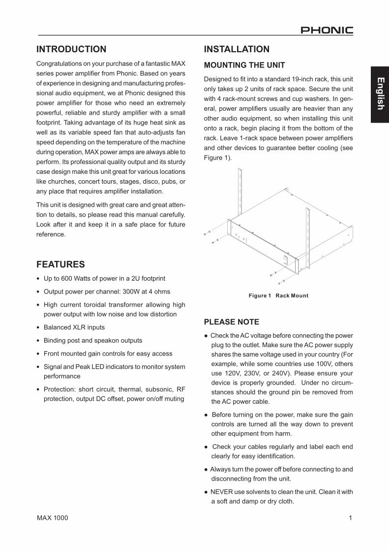
INSTALLATIONMOUNTING THE UNITDesigned to fit into a standard 19-inch rack, this unit only takes up 2 units of rack space. Secure the unit with 4 rack-mount screws and cup washers. In gen-eral, power amplifiers usually are heavier than any other audio equipment, so when installing this unit onto a rack, begin placing it from the bottom of the rack. Leave 1-rack space between power amplifiers and other devices to guarantee better cooling (see Figure 1).
PLEASE NOTE● Check the AC voltage before connecting the power
plug to the outlet. Make sure the AC power supply shares the same voltage used in your country (For example, while some countries use 100V, others use 120V, 230V, or 240V). Please ensure your device is properly grounded. Under no circum-stances should the ground pin be removed from the AC power cable.
● Before turning on the power, make sure the gain controls are turned all the way down to prevent other equipment from harm.
● Check your cables regularly and label each end clearly for easy identification.
● Always turn the power off before connecting to and disconnecting from the unit.
● NEVER use solvents to clean the unit. Clean it with a soft and damp or dry cloth.
2 MAX 1000
English
GETTING STARTEDThe following steps will help you set up your amplifier, and get the levels just right.
1. Ensure that you turn the amplifier’s power switch is off and that the AC power connector is discon-nected.
2. Turn down both level controls.
3. Decide which operating mode is best for your purposes: Stereo, Parallel or Bridge.
Stereo mode is the most common operation mode of amplifiers, where input channel 1 is sent directly through to output channel 1. Similarly, input channel 2 is sent directly through to output channel 2.
In Parallel Mode, users are able to utilize a mono signal from input channel 1 and send the signal through both output channels 1 and 2. These outputs are controlled with their own individual level controls.
Bridge Mode takes the signals from input channel 1 and sends it through a single output. The output power of the both channels is combined when in bridge mode. The signal is output through either out-put channel 1’s speakon connection, or through the binding post connections on channels 1 (+) and 2 (-).
4. Set the Stereo / Parallel / Bridge switch according to your selection.
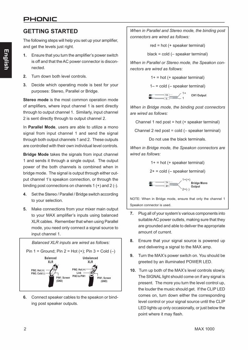
5. Make connections from your mixer main output to your MAX amplifier’s inputs using balanced XLR cables. Remember that when using Parallel mode, you need only connect a signal source to input channel 1.
Balanced XLR inputs are wired as follows:
Pin 1 = Ground; Pin 2 = Hot (+); Pin 3 = Cold (–)
6. Connect speaker cables to the speakon or bind-ing post speaker outputs.
When in Parallel and Stereo mode, the binding post connectors are wired as follows:
red = hot (+ speaker terminal)
black = cold (– speaker terminal)
When in Parallel or Stereo mode, the Speakon con-nectors are wired as follows:
1+ = hot (+ speaker terminal)
1– = cold (– speaker terminal)
When in Bridge mode, the binding post connectors are wired as follows:
Channel 1 red post = hot (+ speaker terminal)
Channel 2 red post = cold (– speaker terminal)
Do not use the black terminals.
When in Bridge mode, the Speakon connectors are wired as follows:
1+ = hot (+ speaker terminal)
2+ = cold (– speaker terminal)
NOTE: When in Bridge mode, ensure that only the channel 1
Speakon connector is used.
7. Plug all of your system’s various components into suitable AC power outlets, making sure that they are grounded and able to deliver the appropriate amount of current.
8. Ensure that your signal source is powered up and delivering a signal to the MAX amp.
9. Turn the MAX’s power switch on. You should be greeted by an illuminated POWER LED.
10. Turn up both of the MAX’s level controls slowly. The SIGNAL light should come on if any signal is present. The more you turn the level control up, the louder the music should get. If the CLIP LED comes on, turn down either the corresponding level control or your signal source until the CLIP LED lights up only occasionally, or just below the point where it may flash.
3MAX 1000
English
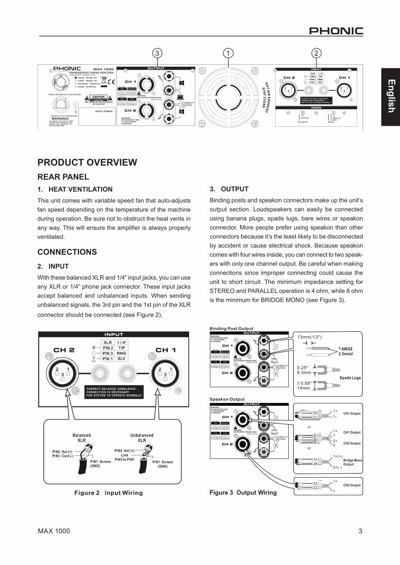
PRODUCT OVERVIEWREAR PANEL1. HEAT VENTILATIONThis unit comes with variable speed fan that auto-adjusts fan speed depending on the temperature of the machine during operation. Be sure not to obstruct the heat vents in any way. This will ensure the amplifier is always properly ventilated.
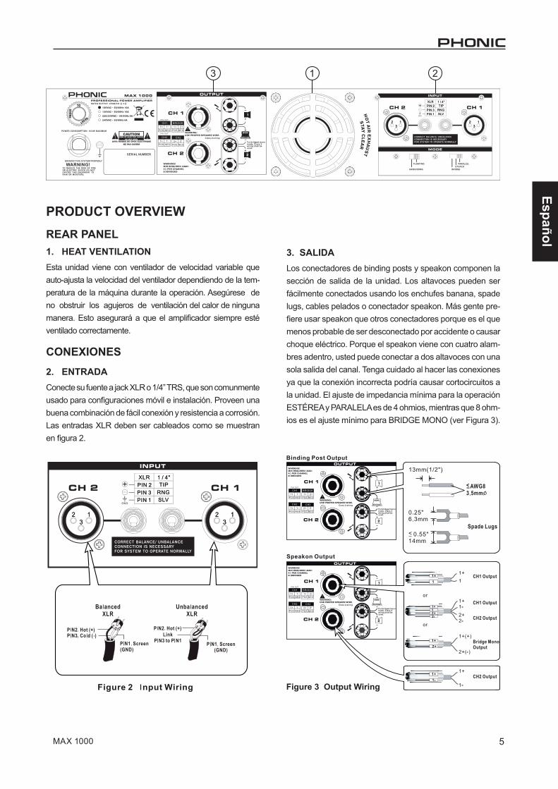
CONNECTIONS2. INPUTWith these balanced XLR and 1/4” input jacks, you can use any XLR or 1/4” phone jack connector. These input jacks accept balanced and unbalanced inputs. When sending unbalanced signals, the 3rd pin and the 1st pin of the XLR
connector should be connected (see Figure 2).
3. OUTPUTBinding posts and speakon connectors make up the unit’s output section. Loudspeakers can easily be connected using banana plugs, spade lugs, bare wires or speakon connector. More people prefer using speakon than other connectors because it’s the least likely to be disconnected by accident or cause electrical shock. Because speakon comes with four wires inside, you can connect to two speak-ers with only one channel output. Be careful when making connections since improper connecting could cause the unit to short circuit. The minimum impedance setting for STEREO and PARALLEL operation is 4 ohm, while 8 ohm is the minimum for BRIDGE MONO (see Figure 3).
3 1 2
Figure 3 Output Wiring
4 MAX 1000
English
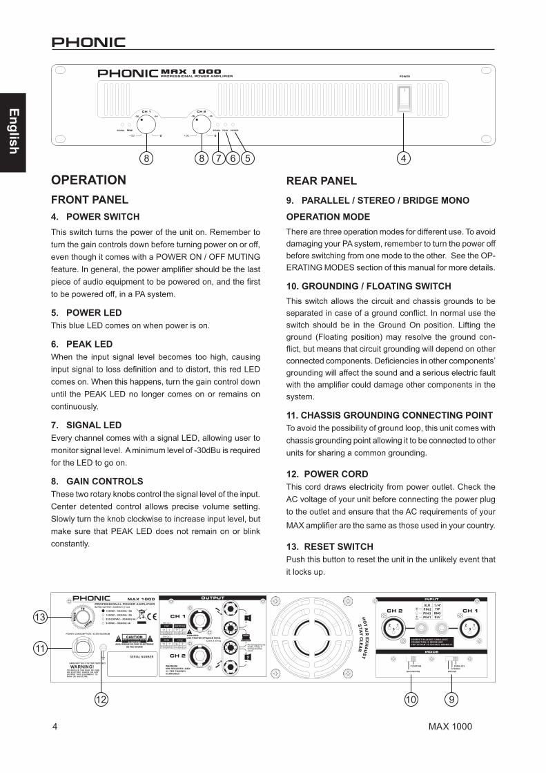
OPERATIONFRONT PANEL4. POWER SWITCHThis switch turns the power of the unit on. Remember to turn the gain controls down before turning power on or off, even though it comes with a POWER ON / OFF MUTING feature. In general, the power amplifier should be the last piece of audio equipment to be powered on, and the first to be powered off, in a PA system.
5. POWER LEDThis blue LED comes on when power is on.
6. PEAK LEDWhen the input signal level becomes too high, causing input signal to loss definition and to distort, this red LED comes on. When this happens, turn the gain control down until the PEAK LED no longer comes on or remains on continuously.
7. SIGNAL LEDEvery channel comes with a signal LED, allowing user to monitor signal level. A minimum level of -30dBu is required for the LED to go on.
8. GAIN CONTROLSThese two rotary knobs control the signal level of the input. Center detented control allows precise volume setting. Slowly turn the knob clockwise to increase input level, but make sure that PEAK LED does not remain on or blink constantly.
REAR PANEL9. PARALLEL / STEREO / BRIDGE MONO
OPERATION MODEThere are three operation modes for different use. To avoid damaging your PA system, remember to turn the power off before switching from one mode to the other. See the OP-ERATING MODES section of this manual for more details.
10. GROUNDING / FLOATING SWITCHThis switch allows the circuit and chassis grounds to be separated in case of a ground conflict. In normal use the switch should be in the Ground On position. Lifting the ground (Floating position) may resolve the ground con-flict, but means that circuit grounding will depend on other connected components. Deficiencies in other components’ grounding will affect the sound and a serious electric fault with the amplifier could damage other components in the system.
11. CHASSIS GROUNDING CONNECTING POINTTo avoid the possibility of ground loop, this unit comes with chassis grounding point allowing it to be connected to other units for sharing a common grounding.
12. POWER CORDThis cord draws electricity from power outlet. Check the AC voltage of your unit before connecting the power plug to the outlet and ensure that the AC requirements of your
MAX amplifier are the same as those used in your country.
13. RESET SWITCHPush this button to reset the unit in the unlikely event that it locks up.
8 48 7 6 5
12 910
11
13
5MAX 1000
English
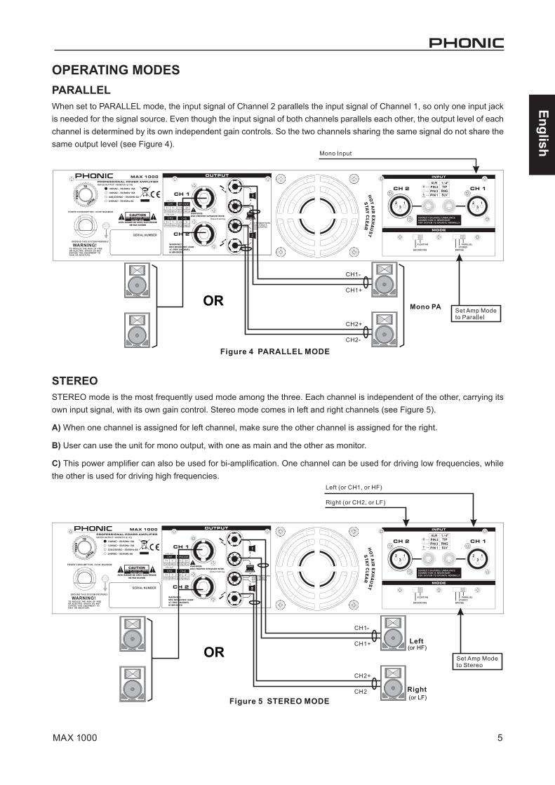
OPERATING MODESPARALLELWhen set to PARALLEL mode, the input signal of Channel 2 parallels the input signal of Channel 1, so only one input jack is needed for the signal source. Even though the input signal of both channels parallels each other, the output level of each channel is determined by its own independent gain controls. So the two channels sharing the same signal do not share the same output level (see Figure 4).
STEREOSTEREO mode is the most frequently used mode among the three. Each channel is independent of the other, carrying its own input signal, with its own gain control. Stereo mode comes in left and right channels (see Figure 5).
A) When one channel is assigned for left channel, make sure the other channel is assigned for the right.
B) User can use the unit for mono output, with one as main and the other as monitor.
C) This power amplifier can also be used for bi-amplification. One channel can be used for driving low frequencies, while the other is used for driving high frequencies.
OR
(or HF)
(or LF)
OR
6 MAX 1000
English
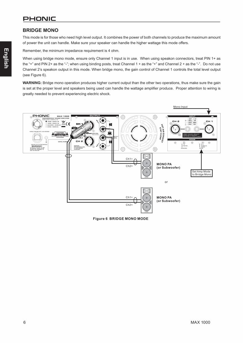
BRIDGE MONOThis mode is for those who need high level output. It combines the power of both channels to produce the maximum amount of power the unit can handle. Make sure your speaker can handle the higher wattage this mode offers.
Remember, the minimum impedance requirement is 4 ohm.
When using bridge mono mode, ensure only Channel 1 input is in use. When using speakon connectors, treat PIN 1+ as the “+” and PIN 2+ as the “-”; when using binding posts, treat Channel 1 + as the “+” and Channel 2 + as the “-”. Do not use Channel 2’s speakon output in this mode. When bridge mono, the gain control of Channel 1 controls the total level output (see Figure 6).
WARNING: Bridge mono operation produces higher current output than the other two operations, thus make sure the gain is set at the proper level and speakers being used can handle the wattage amplifier produce. Proper attention to wiring is greatly needed to prevent experiencing electric shock.
7MAX 1000
English
PROTECTIONThe unit comes with many circuitry protection features that protecting it and the speakers it’s connected to from
harm.
SHORT CIRCUIT: When speakers short circuit, this fea-ture protects the amplifier by cutting off the output current to the speakers.
THERMAL: Heat is created during high level output – especially when operating under bridge mono mode. The unit comes with a variable speed fan that auto-adjusts the fan speed depending on the temperature of the machine. However, if for some reason the unit can not effectively vent out excessive heat, this feature will protect the unit from over-heating by shutting the unit down.
OUTPUT DC OFFSET: When a direct current enters the connection between the power amplifier and speakers, it will negatively affect the speakers by causing the drivers and cones to work under stressful conditions. This feature ensures this does not happen by cutting off the output cur-rent to the speakers when such a situation occurs.
POWER ON / OFF MUTING: There is a two to three sec-ond delay before the unit sends out any signal. During this short delay, the entire system will be muted ensuring no signal affects your signal.
SUBSONIC: Frequencies below 10Hz contain high level of energy that can be harmful and stressful to many speakers. Since the normal human listening range is between 20 Hz and 20 kHz, this unit comes with a feature that helps filter out any frequency that is below 10 Hz to protect your speakers.
RF PROTECTION: Radio waves are everywhere. This fea-ture prevents radio frequency interference from affect your signal by filtering out signals above 200 kHz. This ensures that radio program signals do not entering the unit.
AC POWER CONSIDERATIONSThe voltage level of the MAX amplifier will depend on your region. Ensure that the local voltage levels are identical by those required by your amplifier before attempting to connect it to an AC outlet. This is particularly important if you intend to take the amplifier overseas.
Users are advised that they do not remove the ground pin on the MAX amplifier’s AC connector under any circum-stances.
As the amount of power that the MAX amplifier consumes can differ greatly depending on the program material being amplified, it’s important that a stiff supply of AC power is available for the unit. The more power available to the unit, the better the output will sound; particularly in low frequen-cy peaks. If you have more than one amplifier sharing a single AC outlet, turning them on at the same time should be avoided at all costs. Turning them on in sequential order will help prevent tripping any circuit breakers.
INPUT WIRINGFor balanced signals, users should use 3-conductor shielded cable with XLR connectors on either end. For unbalanced signals, 2-conductor shielded cable with XLR connectors on either end can be used instead. Balanced cables should be wired according to Audio Engineering Society standards.
XLR? The name of this kind of connector is derived from an X connector from Cannon. These are the large, round connectors that contain three small pins that are arranged in a triangular shape.
Hot (+) – Pin 2Cold (–) – Pin 3
Shield (Gnd) – Pin 1
8 MAX 1000
English
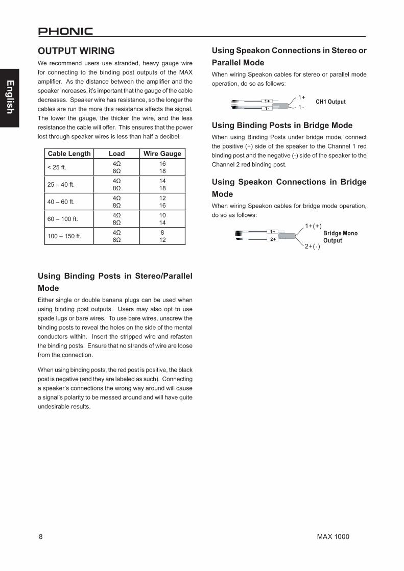
OUTPUT WIRINGWe recommend users use stranded, heavy gauge wire for connecting to the binding post outputs of the MAX amplifier. As the distance between the amplifier and the speaker increases, it’s important that the gauge of the cable decreases. Speaker wire has resistance, so the longer the cables are run the more this resistance affects the signal. The lower the gauge, the thicker the wire, and the less resistance the cable will offer. This ensures that the power lost through speaker wires is less than half a decibel.
Using Binding Posts in Stereo/Parallel ModeEither single or double banana plugs can be used when using binding post outputs. Users may also opt to use spade lugs or bare wires. To use bare wires, unscrew the binding posts to reveal the holes on the side of the mental conductors within. Insert the stripped wire and refasten the binding posts. Ensure that no strands of wire are loose from the connection.
When using binding posts, the red post is positive, the black post is negative (and they are labeled as such). Connecting a speaker’s connections the wrong way around will cause a signal’s polarity to be messed around and will have quite undesirable results.
Using Speakon Connections in Stereo or Parallel ModeWhen wiring Speakon cables for stereo or parallel mode operation, do so as follows:
Using Binding Posts in Bridge ModeWhen using Binding Posts under bridge mode, connect the positive (+) side of the speaker to the Channel 1 red binding post and the negative (-) side of the speaker to the Channel 2 red binding post.
Using Speakon Connections in Bridge ModeWhen wiring Speakon cables for bridge mode operation, do so as follows:
Cable Length Load Wire Gauge
< 25 ft. 4Ω8Ω
1618
25 – 40 ft. 4Ω8Ω
1418
40 – 60 ft. 4Ω8Ω
1216
60 – 100 ft. 4Ω8Ω
1014
100 – 150 ft. 4Ω8Ω
812
9MAX 1000
English
TROUBLESHOOTINGNo Power● Perhaps the most obvious question, but is it
plugged in?
● Is the AC outlet that the MAX amp is connected to active? Test it with a lamp.
● Is the power switched on?
● Is the power LED illuminated? If not, make sure that the unit is plugged in, turned on and the AC outlet is live. If it is illuminated, check the “No Sound” section below.
● Failing all of this, the most likely cause is the fuse inside the amplifier’s power supply has blown. As users cannot service this part, please contact your country’s distributor for assistance. You can find their details on www.phonic.com/where.
No Sound● Have you turned up the level controls? If not, turn
them up slowly to see if you can hear anything.
● Is your source material turned up and active? Ensure that the level of the mixer (or whichever device is connected to your amplifier’s inputs) is high enough to produce a signal. The signal LED on the front panel should give you some idea of whether this is so.
● Check the temperature of the unit by putting a hand nearby. If there is no heat, you’re fine. If you can feel obvious heat emitting from the unit, it’s possible that the thermal protection function has kicked it. You may need to turn the unit off and wait for it to cool down before it can function as normal.
● Ensure your speakers to make sure they are working correctly. If your speakers have fuses, check if they’ve blown.
Poor sound● Is the signal loud and distorted? If so, turn down
the level of the source signal.
● Is the clip LED flashing quickly or staying con-stantly on? If so, try reducing the Amplifier’s level controls.
● Ensure that the input connectors are pushed firmly into the jack. Make sure your speakers are connected correctly.
● Try connecting a set of headphones into your signal source to see how the signal sounds there. If you’re getting the same result, then the problem is your source rather than the amplifier.

10 MAX 1000
English
Stereo Mode (driving both channels) Continuous Average Output Power Per Channel
8Ω EIA 1kHz 0.1%THD 200W
4Ω EIA 1kHz 0.1%THD 300W
Bridge Mono Mode Continuous Average Output Power
8Ω EIA 1kHz 0.1%THD 600W
Output Circuitry Class AB
Input Sensitivity @ 8Ω 1.23V (+4dBu)
Distortion (SMPTE-IM) <0.01%
Noise (unweighted 20 Hz - 20 kHz below rated output) 100dB
Damping Factor >300 @ 8Ω
Frequency Response 20 Hz-20KHz, +0/-1dB; -3dB points: 5Hz-50KHz
Input Impedance 20 kΩ balanced, 10 kΩ unbalanced
Cooling Continuous variable-speed fan, front-to-rear air flow
Connectors (each channel) Input: XLR; Output: Speakon and binding posts
Indicators Power: Blue LED; Signal: Green LED; Peak: Red LED
Controls
Front Panel CH1 & CH2 GAIN knobs with 21 detents
Rear Panel Slide switches: Operation mode: Parallel, Bridge, Stereo; Current-Break reset button
Protection Circuitry Short circuit, thermal, subsonic, RF protection, output DC offset, power on/off muting
Power Comsuption 600W
Power Requirement (depends on region) 100~120VAC, 220~240VAC, 50/60Hz
Dimensions (WxHxD) 482.6 x 88 x 415 mm (19" x 3.46" x 15.9")
Weight 14.6 kg (32.2 lbs)
SPECIFICATIONS

11MAX 1000
English
DIMENSIONS
All measurements are shown in mm/inches.

SERVICE AND REPAIRFor replacement parts, service and repairs please contact the Phonic distributor in your country. Phonic does not release service manuals to consumers, and advice users to not attempt any self repairs, as doing so voids all warranties. You can locate a dealer near you at http://www.phonic.com/where/.
WARRANTY INFORMATIONPhonic stands behind every product we make with a no-hassles warranty. Warranty coverage may be extended, depending on your region. Phonic Corporation warrants this product for a minimum of one year from the original date of purchase against defects in material and workmanship under use as instructed by the user’s manual. Phonic, at its option, shall repair or replace the defective unit covered by this warranty. Please retain the dated sales receipt as evidence of the date of purchase. You will need it for any warranty service. No returns or repairs will be accepted without a proper RMA number (return merchandise authorization). In order to keep this warranty in effect, the product must have been handled and used as prescribed in the instructions accompanying this warranty. Any tampering of the product or attempts of self repair voids all warranty. This warranty does not cover any damage due to accident, misuse, abuse, or negligence. This warranty is valid only if the product was purchased new from an authorized Phonic dealer/distributor. For complete warranty policy information, please visit http://www.phonic.com/warranty/.
CUSTOMER SERVICE AND TECHNICAL SUPPORTWe encourage you to visit our online help at http://www.phonic.com/support/. There you can find answers to frequently asked questions, tech tips, driver downloads, returns instruction and other helpful information. We make every effort to answer your questions within one business day.
[email protected] http://www.phonic.com
Español
1MAX 1000
Phonic se reserva el derecho de mejorar o alterar cualquier información provista dentro de este documento sin previo aviso.
INTRODUCCIÓN............................................................1
CARACTERÍSTICAS...................................................................1
INSTALACIÓN. . . . . . . . . . . . . . . . . . . . . . . . . . . . . . . . . . . . . . . . . . . . . . . . . . . . . . . . .1
PRIMEROS PASOS..........................................................................2
PRODUCT OVERVIEW............................................................3
PANEL DORSAL...................................................................3
CONEXIONES.....................................................................3
OPERACIÓN..........................................................................4
PANEL FRONTAL.........................................................4
PANEL DORSAL......................................................................4
MODO DE OPERACIÓN.................................................................5
PROTECCIONES.....................................................................7
CONSIDERACIONES DE CORRIENTE ALTERNATIVA..........................7
ENTRADA DE CABLEADO.................................................................7
SALIDA DE CABLEADO......................................................................8
RESOLUCIÓN DE PROBLEMAS...............................................9
ESPECIFICACIONES..................................................................10
DIMENSIONES..............................................................11
CONTENIDO
MANUAL DEL USUARIO
Español
2 MAX 1000

Español
3MAX 1000
INTRODUCCIÓNGracias por comprar un amplificador potenciado de la serie MAX Plus. Basado en años de experiencia en el diseño y la fabricación del equipo de audio profesional, en Phonic dise-ñamos este amplificador potenciado para los que necesitan un amplificador extremadamente poderoso, confiable y robusto con un tamaño pequeño. Aprovechándose de su disipador de calor enorme así como su ventilador de velocidad variable que auto-ajusta la velocidad del ventilador dependiendo de la temperatura de la máquina durante la operación, los amplifica-dores de potencia MAX Plus siempre están listos para ejecutar. Su salida de calidad profesional y su diseño del estuche robusto hace que esta unidad sea maravillosa para varios sitios como iglesias, giros de concierto, escenarios, disco, pubs o cualquier lugar que requiere la instalación del amplificador.
Esta unidad está diseñada con gran cuidado y gran atención a los detalles, por eso lea por favor este manual cuidadosamente. Léalo y guardelo en un lugar seguro para referencia futura.
CARACTERÍSTICAS● Hasta 600 Watts con solamente 2 unidades
● Salida: 300W todo a 4 ohms
● Transformador toroidal de alta corriente permi-tiendo salida de alta energía con ruido bajo y baja distorsión
● Entradas balanceadas XLR
● Salidas de binding post y speakon
● Controles de ganancia montados en la parte frontal para fácil acceso
● Indicadores LED de Sañal y Pico para monitorear el funcionamiento
● Protección: cortocircuito, termal, subsónico, protección RF, offset de DC de salida, enmudecimiento de encendido/apagado de energía
INSTALACIÓNMONTANDO LA UNIDADDiseñado para caber en un rack estándar de 19 pul-gadas, esta unidad toma solamente 2 unidades de espacio de rack. Asegura esta unidad con 4 tornillos y arandelas de montaje en rack. En general, los am-plificadores de potencia son usualmente más pesados que cualquier otro equipo de audio, así que al instalar esta unidad sobre un rack, comiencen a colocarlo desde la parte inferior del rack. Deje 1 espacio rack entre los amplificadores de potencia y otros dispositi-vos para garantizar mejor enfriamiento (ver Figura 1).
INICIANDO● Chequee el voltaje AC antes de conectar el enchufe
de energía con la salida. Asegúrese de que la fuente de energía AC sea de mismo voltaje usado en su país (Por ejemplo, mientras que algunos países utilizan 100V, otros utilizan 120V, 230V o 240V). Asegúrese por favor que su dispositivo esté puesto a tierra correctamente.
● Antes de encender, cerciórese de que los controles de ganancia están girados hacia abajo completamente para prevenir que se dañe otro equipo
● Chequee sus cables regularmente y etiquete cada extremo claramente para identificación fácil.
● Siempre apague la energía antes de conectar con y de desconectar de la unidad.
● NUNCA utilice solventes para limpiar la unidad.Limpíela con un paño suave y húmedo o seco.
Español
4 MAX 1000
PRIMEROS PASOSLas etapas siguientes le ayudarán a configurar su amplificador y ajustar correctamente los niveles.
1. Asegúrese que el interruptor de potencia del amplificador esté apagado y que el conector de alimentación esté desconectado.
2. Baje los dos controles de nivel.
3. Decida qué modo de funcionamiento es el mejor para sus propósitos: Stereo, Parallel o Bridge.
El modo estéreo es el modo de funcionamiento más común de los amplificadores, donde se envía el canal de entrada 1 directamente a través del canal de salida 1. De manera similar, el canal de entrada 2 se envía directamente a través del canal de salida 2.
El modo paralelo, los usuarios pueden utilizar una señal mono desde el canal de entrada 1 y enviar la señal a través de ambos canales de salida 1 y 2. Estas salidas se controlan con sus propios controles de nivel individuales.
El modo Bridge toma las señales del canal de entrada 1 y la envía a través de una única salida. En modo Bridge la potencia de salida de ambos canales se combina. La señal se emite a través de sea la conexión speakon de salida del canal 1, sea a través de las conexiones binding post en los canales 1 (+) y 2 (-).
4. Ajuste el interruptor Estéreo / Parallel / Bridge según su decisión.
5. Haga las conexiones de su salida de la mezcla principal a las entradas de su amplificador MAX utilizando cables XLR balanceados. Recuerde que cuando se utiliza el modo paralelo, sólo tiene que conectar una fuente de señal al canal de entrada 1.
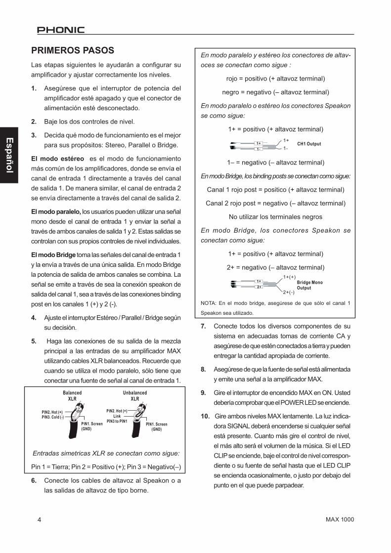
Entradas simetricas XLR se conectan como sigue:
Pin 1 = Tierra; Pin 2 = Positivo (+); Pin 3 = Negativo(–)
6. Conecte los cables de altavoz al Speakon o a las salidas de altavoz de tipo borne.
En modo paralelo y estéreo los conectores de altav-oces se conectan como sigue :
rojo = positivo (+ altavoz terminal)
negro = negativo (– altavoz terminal)
En modo paralelo o estéreo los conectores Speakon se como sigue:
1+ = positivo (+ altavoz terminal)
1– = negativo (– altavoz terminal)
En modo Bridge, los binding posts se conectan como sigue:
Canal 1 rojo post = positico (+ altavoz terminal)
Canal 2 rojo post = negativo (– altavoz terminal)
No utilizar los terminales negros
En modo Bridge, los conectores Speakon se conectan como sigue:
1+ = positivo (+ altavoz terminal)
2+ = negativo (– altavoz terminal)
NOTA: En el modo bridge, asegúrese de que sólo el canal 1
Speakon sea utilizado.
7. Conecte todos los diversos componentes de su sistema en adecuadas tomas de corriente CA y asegúrese de que estén conectados a tierra y pueden entregar la cantidad apropiada de corriente.
8. Asegúrese de que la fuente de señal está alimentada y emite una señal a la amplificador MAX.
9. Gire el interruptor de encendido MAX en ON. Usted debería comprobar que el POWER LED se enciende.
10. Gire ambos niveles MAX lentamente. La luz indica-dora SIGNAL deberá encenderse si cualquier señal está presente. Cuanto más gire el control de nivel, el más alto será el volumen de la música. Si el LED CLIP se enciende, baje el control de nivel correspon-diente o su fuente de señal hasta que el LED CLIP se encienda ocasionalmente, o justo por debajo del punto en el que puede parpadear.
Español
5MAX 1000
PRODUCT OVERVIEWREAR PANEL1. HEAT VENTILATIONEsta unidad viene con ventilador de velocidad variable que auto-ajusta la velocidad del ventilador dependiendo de la tem-peratura de la máquina durante la operación. Asegúrese de no obstruir los agujeros de ventilación del calor de ninguna manera. Esto asegurará a que el amplificador siempre esté ventilado correctamente.
CONEXIONES2. ENTRADAConecte su fuente a jack XLR o 1/4” TRS, que son comunmente usado para configuraciones móvil e instalación. Proveen una buena combinación de fácil conexión y resistencia a corrosión. Las entradas XLR deben ser cableados como se muestran en figura 2.
3. SALIDALos conectadores de binding posts y speakon componen la sección de salida de la unidad. Los altavoces pueden ser fácilmente conectados usando los enchufes banana, spade lugs, cables pelados o conectador speakon. Más gente pre-fiere usar speakon que otros conectadores porque es el que menos probable de ser desconectado por accidente o causar choque eléctrico. Porque el speakon viene con cuatro alam-bres adentro, usted puede conectar a dos altavoces con una sola salida del canal. Tenga cuidado al hacer las conexiones ya que la conexión incorrecta podría causar cortocircuitos a la unidad. El ajuste de impedancia mínima para la operación ESTÉREA y PARALELA es de 4 ohmios, mientras que 8 ohm-ios es el ajuste mínimo para BRIDGE MONO (ver Figura 3).
3 1 2
Figure 3 Output Wiring
Español
6 MAX 1000
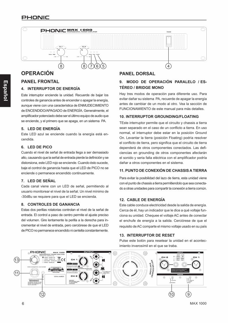
OPERACIÓNPANEL FRONTAL4. INTERRUPTOR DE ENERGÍAEste interruptor enciende la unidad. Recuerde de bajar los controles de ganancia antes de encender o apagar la energía, aunque viene con una característica de ENMUDECIMIENTO de ENCENDIDO/APAGADO de ENERGÍA. Generalmente, el amplificador potenciado debe ser el último equipo de audio que se enciende, y el primero que se apaga, en un sistema PA.
5. LED DE ENERGÍAEste LED azul se enciende cuando la energía está en-cendida.
6. LED DE PICOCuando el nivel de señal de entrada llega a ser demasiado alto, causando que la señal de entrada pierde la definición y se distorsiona, este LED rojo se enciende. Cuando ésto sucede, baje el control de ganancia hasta que el LED de PICO no se enciende o permanece encendido continuamente.
7. LED DE SEÑALCada canal viene con un LED de señal, permitiendo al usuario monitorear el nivel de la señal. Un nivel mínimo de -30dBu se requiere para que el LED se encienda.
8. CONTROLES DE GANANCIAEstas dos perillas rotatorias controlan el nivel de la señal de entrada. El control a paso de centro permite el ajuste preciso del volumen. Gire lentamente la perilla a la derecha para in-crementar el nivel de entrada, pero cerciórese de que el LED de PICO no permanece encendido ni centella constantemente.
PANEL DORSAL9. MODO DE OPERACIÓN PARALELO / ES-TÉREO / BRIDGE MONOHay tres modos de operación para diferente uso. Para evitar dañar su sistema PA, recuerde de apagar la energía antes de cambiar de un modo al otro. Vea la sección de FUNCIONAMIENTO de este manual para más detalles.
10. INTERRUPTOR GROUNDING/FLOATINGTEste interruptor permite que el circuito y chassis a tierra sean separado en el caso de un conflicto a tierra. En uso normal, el interruptor debe estar en la posición Ground On. Levantar la tierra (posición Floating) podría resolver el conflicto de tierra, pero significa que el circuito de tierra dependerá de otros componentes conectados. Las defi-ciencias en grounding de otros componentes afectarán el sonido y seria falla eléctrica con el amplificador podría dañar a otros componentes en el sistema.
11. PUNTO DE CONEXIÓN DE CHASSIS A TIERRA
Para evitar la posibilidad del lazo de tierra, esta unidad viene con el punto de chassis a tierra permitiendolo que sea conecta-do a otras unidades para compartir la conexión a tierra común.
12. CABLE DE ENERGÍAEste cable conduce electricidad desde la salida de energía. Cerca de él, hay un indicador que le dice a qué voltaje fun-ciona su unidad. Chequee el voltaje AC antes de conectar el enchufe de energía a la salida. Cerciórese de que el
requisito de AC comparte el mismo voltaje usado en su país
13. INTERRUPTOR DE RESETPulse este botón para resetear la unidad en el acontec-imiento inverosímil en el que se traba.
8 48 7 6 5
12 910
11
13
Español
7MAX 1000
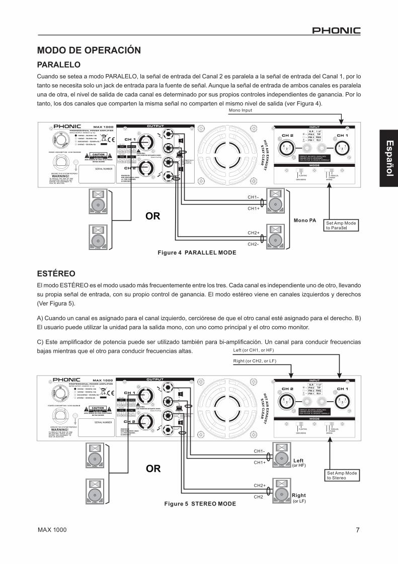
MODO DE OPERACIÓNPARALELOCuando se setea a modo PARALELO, la señal de entrada del Canal 2 es paralela a la señal de entrada del Canal 1, por lo tanto se necesita solo un jack de entrada para la fuente de señal. Aunque la señal de entrada de ambos canales es paralela una de otra, el nivel de salida de cada canal es determinado por sus propios controles independientes de ganancia. Por lo tanto, los dos canales que comparten la misma señal no comparten el mismo nivel de salida (ver Figura 4).
ESTÉREOEl modo ESTÉREO es el modo usado más frecuentemente entre los tres. Cada canal es independiente uno de otro, llevando su propia señal de entrada, con su propio control de ganancia. El modo estéreo viene en canales izquierdos y derechos (Ver Figura 5).
A) Cuando un canal es asignado para el canal izquierdo, cerciórese de que el otro canal esté asignado para el derecho. B) El usuario puede utilizar la unidad para la salida mono, con uno como principal y el otro como monitor.
C) Este amplificador de potencia puede ser utilizado también para bi-amplificación. Un canal para conducir frecuencias bajas mientras que el otro para conducir frecuencias altas.
OR
(or HF)
(or LF)
OR
Español
8 MAX 1000
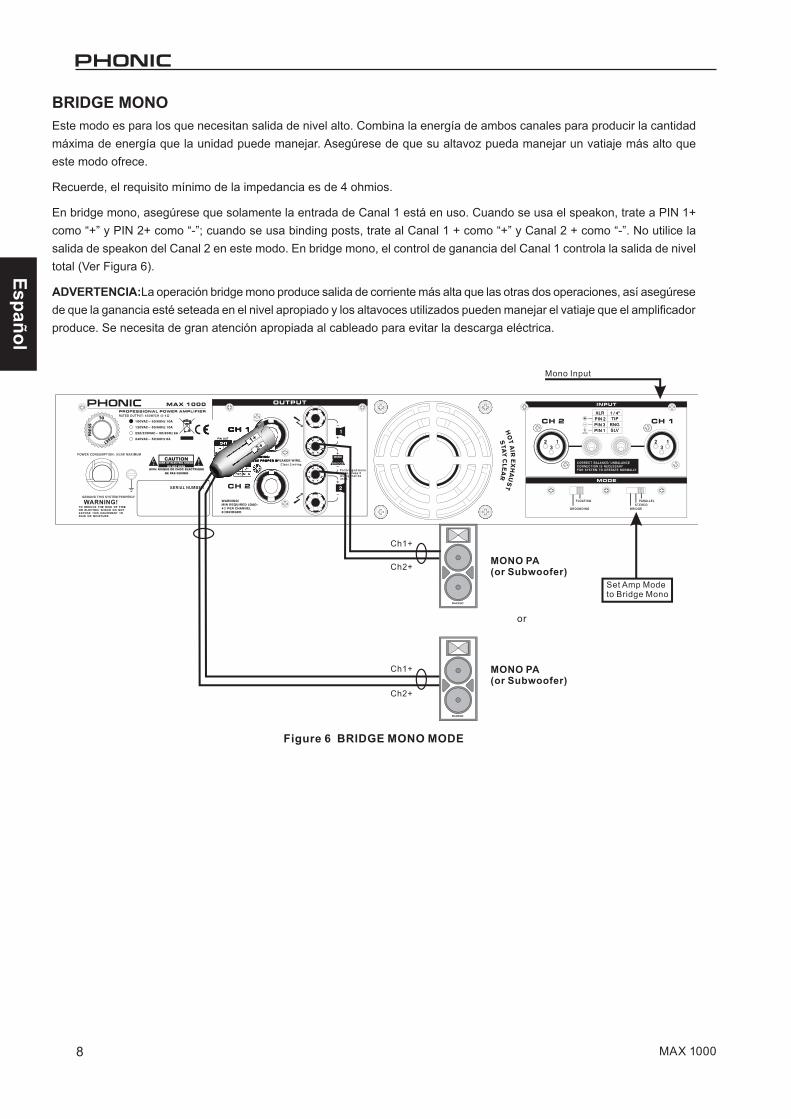
BRIDGE MONOEste modo es para los que necesitan salida de nivel alto. Combina la energía de ambos canales para producir la cantidad máxima de energía que la unidad puede manejar. Asegúrese de que su altavoz pueda manejar un vatiaje más alto que este modo ofrece.
Recuerde, el requisito mínimo de la impedancia es de 4 ohmios.
En bridge mono, asegúrese que solamente la entrada de Canal 1 está en uso. Cuando se usa el speakon, trate a PIN 1+ como “+” y PIN 2+ como “-”; cuando se usa binding posts, trate al Canal 1 + como “+” y Canal 2 + como “-”. No utilice la salida de speakon del Canal 2 en este modo. En bridge mono, el control de ganancia del Canal 1 controla la salida de nivel total (Ver Figura 6).
ADVERTENCIA:La operación bridge mono produce salida de corriente más alta que las otras dos operaciones, así asegúrese de que la ganancia esté seteada en el nivel apropiado y los altavoces utilizados pueden manejar el vatiaje que el amplificador produce. Se necesita de gran atención apropiada al cableado para evitar la descarga eléctrica.
Español
9MAX 1000
PROTECCIONESLa unidad viene con muchas características de protección de circuito para prevenir la unidad y los altavoces conect-
ados del daño.
CORTOCIRCUITO: Cuando los altavoces se ponen en cortocircuitos, esta característica protege el amplificador cortando la corriente de salida a los altavoces.
TERMAL: El calor se crea durante la salida de alto nivel - especialmente durante la operación de bridge. La unidad viene con ventilador de velocidad variable que auto-ajusta la velocidad dependiendo de la temperatura de la máquina durante la operación. Sin embargo, por alguna razón la unidad no podía sacar con eficacia el calor excesivo, esta característica protegería la unidad contra el sobre- calen-tamiento apagando su energía.
OFFSET DE SALIDA DC: Cuando la corriente directa entra a la conexión entre el amplificador de potencia y los altavoces, lastima a los altavoces causando los controla-dores y conos funcionar bajo tensión. Esta característica evita que ésto suceda cortando la corriente de salida a los altavoces cuando ocurre tal situación.
ENMUDECIMIENTO DE ENCENDIDO / APAGADO DE ENERGÍA: Hay dos a tres segundos de retardo antes de que la unidad envíe cualquier señal. Durante estos 2-3 segundos, el sistema estará en mudo, no existe señal en esta unidad.
SUBSÓNICO: Las frecuencias debajo de 10Hz contienen al to ni vel de en erg ía q ue pu ede n se r da ño sa s y agotadoras para muchos altavoces. Como el rango de la escucha humana normal es de 20Hz a 20KHz, esta unidad viene con una característica que ayuda a filtrar cualquier frecuencia que está debajo de 10Hz para evitar que se dañen los altavoces.
PROTECCIÓN RF: La Radiofrecuencia está por todas partes. Esta característica previene interferencia de la radiofrecuencia filtrando la señal de la frecuencia que está sobre 200KHz. Esto ayuda a prevenir que las señales del programa de radio entran a esta unidad.
CONSIDERACIONES DE CORRIEN-TE ALTERNATIVAEl nivel de voltaje del amplificador MAX dependerá de su región. Asegúrese de que los niveles de voltaje local son idénticos a los requeridos por el amplificador antes de intentar conectarse a una toma de CA. Esto es espe-cialmente importante si usted tiene la intención de llevar el amplificador al extranjero.
Los usuarios se les recomienda que no retire el contacto de tierra en el conector de CA del amplificador MAX bajo ninguna circunstancia.
Como la cantidad de energía que consume el amplificador MAX puede variar mucho dependiendo del tipo de señal que está siendo amplificado, es importante que un sumin-istro constante de alimentación de CA esté disponible para la unidad. Cuando más potencia haya para la unidad, mejor sonará la señal de salida, particularmente en los picos de baja frecuencia. Si usted tiene más de un amplificador compartiendo una sola toma de corriente AC, NUNCA encenderlos al mismo tiempo. Encenderlos uno tras otro ayudará a evitar cualquier salto de disyuntores.
ENTRADA DE CABLEADOPara señales balanceadas, los usuarios deben utilizar cables blindados triples con conectores XLR en cada extremo. Para señales no balanceadas, cables blindados dobles con conectores XLR en cada extremo se pueden utilizar en su lugar. Los cables balanceados deben ser conectados de acuerdo con las normas de la Sociedad de Ingeniería de Audio.
XLR? XLR? El nombre de este tipo de conector se deriva de un conector X de Cannon. Éstos son los grandes conec-tores redondos que contienen tres pequeños contactos dispuestos en forma triangular.
Positivo (+) – Contacto 2Negativo (–) – Contacto 3 Tierra (Gnd) – Contacto 1
Español
10 MAX 1000
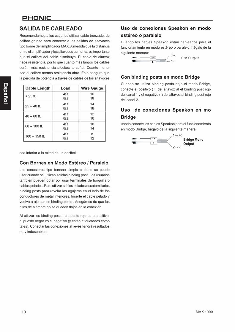
SALIDA DE CABLEADORecomendamos a los usuarios utilizar cable trenzado, de calibre grueso para conectar a las salidas de altavoces tipo borne del amplificador MAX. A medida que la distancia entre el amplificador y los altavoces aumenta, es importante que el calibre del cable disminuya. El cable de altavoz hace resistencia, por lo que cuanto más largos los cables serán, más resistencia afectara la señal. Cuanto menor sea el calibre menos resistencia abra. Esto asegura que la pérdida de potencia a través de cables de los altavoces
sea inferior a la mitad de un decibel.
Con Bornes en Modo Estéreo / ParaleloLos conectores tipo banana simple o doble se puede usar cuando se utilizan salidas binding post. Los usuarios también pueden optar por usar terminales de horquilla o cables pelados. Para utilizar cables pelados desatornillarlos binding posts para revelar los agujeros en el lado de los conductores de metal interiores. Inserte el cable pelado y vuelva a ajustar los binding posts . Asegúrese de que los hilos de alambre no se queden flojos en la conexión.
Al utilizar los binding posts, el puesto rojo es el positivo, el puesto negro es el negativo (y están etiquetados como tales). Conectar las conexiones al revés tendrá resultados muy indeseables.
Uso de conexiones Speakon en modo estéreo o paraleloCuando los cables Speakon estan cableados para el funcionamiento en modo estéreo o paralelo, hágalo de la siguiente manera:
Con binding posts en modo BridgeCuando se utiliza binding posts bajo el modo Bridge, conecte el positivo (+) del altavoz al el binding post rojo del canal 1 y el negativo (-) del altavoz al binding post rojo del canal 2.
Uso de conexiones Speakon en mo Bridgeuando conecte los cables Speakon para el funcionamiento en modo Bridge, hágalo de la siguiente manera:
Cable Length Load Wire Gauge
< 25 ft. 4Ω8Ω
1618
25 – 40 ft. 4Ω8Ω
1418
40 – 60 ft. 4Ω8Ω
1216
60 – 100 ft. 4Ω8Ω
1014
100 – 150 ft. 4Ω8Ω
812
Español
11MAX 1000
RESOLUCIÓN DE PROBLEMASNo hay alimentación Tal vez es la pregunta más obvia, pero ¿está e
chufado?
● ¿Está la toma de CA conectada al amplificador-MAX alimentada? Pruébelo con una lámpara.
● ¿Se ha activado la alimentación?
● ¿Está el LED de alimentación iluminado? Si no es así, asegúrese de que la unidad esté enchufada, encendida y la toma de corriente está activa. Si está iluminado, mire a la sección “Sin Sonido” a continuación.
● Al fallar todo esto, la causa más probable es que el fusible en el interior de la fuente de alimentación del amplificador se ha fundido. Como los usuarios no pueden reparar la pieza, por favor póngase en contacto con su distribuidor de su país para obtener asistencia. Puede encontrar sus datos en www.phonic.com /where.
No hay sonido● ¿Ha girado los controles de nivel? Si no, girarlos-
lentamente para ver si se puede oír algo.
● ¿Está el material de origen de señal presente y activo? Asegúrese de que el nivel de la mezcla-dora (o cualquier dispositivo que se conecta a las entradas de su amplificador) es lo suficientemente alto como para producir una señal. La señal LED en el panel frontal debería darle una idea de si esto es así.
● Compruebe la temperatura de la unidad acercando la mano. Si no hay calor está Usted bien. Si puede sentir claramente el calor que emite el aparato es posible que la función de protección térmica se haya estropeado. Puede que tenga que apagar la unidad y esperar que se enfríe antes de que pueda funcionar con normalidad.
● Asegúrese de que los altavoces funcionan correctamente. Si los altavoces tienen fusibles, verificar si se han fundido.
Sonido deficiente● ¿Esta la señal alta y distorsionada? Si es así,
bajeel nivel de la señal fuente.
● ¿Está el clip LED parpadeando rápidamente o manteniéndose iluminado permanentemente? Si es así, trate de reducir los niveles del amplificador.
● Asegúrese de que los conectores de entrada están insertos firmemente en la toma. Asegúrese de que los altavoces estén conectados correctamente.
● Intente conectar un juego de auriculares en la fuente de señal para ver cómo suena la señal allí. Si usted obtiene el mismo resultado, entonces el problema es su fuente más que el amplificador.
Español
12 MAX 1000
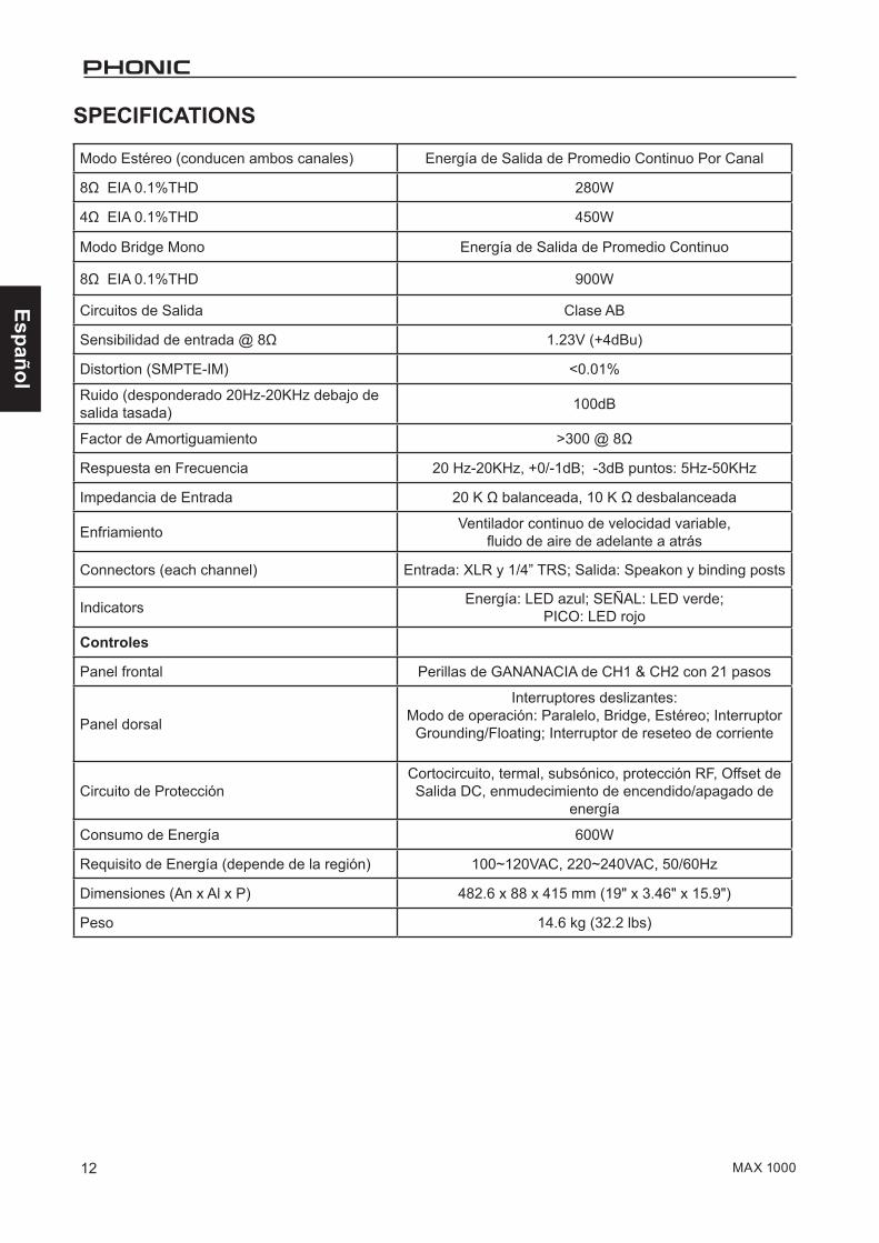
Modo Estéreo (conducen ambos canales) Energía de Salida de Promedio Continuo Por Canal
8Ω EIA 0.1%THD 280W
4Ω EIA 0.1%THD 450W
Modo Bridge Mono Energía de Salida de Promedio Continuo
8Ω EIA 0.1%THD 900W
Circuitos de Salida Clase AB
Sensibilidad de entrada @ 8Ω 1.23V (+4dBu)
Distortion (SMPTE-IM) <0.01%
Ruido (desponderado 20Hz-20KHz debajo de salida tasada) 100dB
Factor de Amortiguamiento >300 @ 8Ω
Respuesta en Frecuencia 20 Hz-20KHz, +0/-1dB; -3dB puntos: 5Hz-50KHz
Impedancia de Entrada 20 K Ω balanceada, 10 K Ω desbalanceada
Enfriamiento Ventilador continuo de velocidad variable,fluido de aire de adelante a atrás
Connectors (each channel) Entrada: XLR y 1/4” TRS; Salida: Speakon y binding posts
Indicators Energía: LED azul; SEÑAL: LED verde;PICO: LED rojo
Controles
Panel frontal Perillas de GANANACIA de CH1 & CH2 con 21 pasos
Panel dorsal
Interruptores deslizantes:Modo de operación: Paralelo, Bridge, Estéreo; Interruptor
Grounding/Floating; Interruptor de reseteo de corriente
Circuito de ProtecciónCortocircuito, termal, subsónico, protección RF, Offset de Salida DC, enmudecimiento de encendido/apagado de
energía
Consumo de Energía 600W
Requisito de Energía (depende de la región) 100~120VAC, 220~240VAC, 50/60Hz
Dimensiones (An x Al x P) 482.6 x 88 x 415 mm (19" x 3.46" x 15.9")
Peso 14.6 kg (32.2 lbs)
SPECIFICATIONS
Español
13MAX 1000
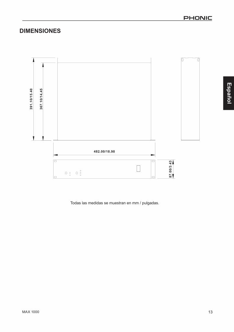
DIMENSIONES
Todas las medidas se muestran en mm / pulgadas.

Español
14 MAX 1000
SERVICIO Y REPARACIÓNPara refacciones de reemplazo y reparaciones, por favor póngase en contacto con nuestro distribuidor de Phonic en su país. Phonic no distribuye manuales de servicio directamente a los consumidores y, avisa a los usuarios que no intenten hacer cualquier reparación por si mismo, haciendo ésto invalidará todas las garantías del equipo. Puede encontrar un distribuidor cerca de usted en http://www.phonic.com/where/.
INFORMACIÓN DE LA GARANTIAPhonic respalda cada producto que hacemos con una garantía sin enredo. La cobertura de garantía podría ser ampliada dependiendo de su región. Phonic Corporation garantiza este producto por un mínimo de un año desde la fecha original de su compra, contra defectos en materiales y mano de obra bajo el uso que se instruya en el manual del usuario. Phonic, a su propia opinión, reparará o cambiará la unidad defectuosa que se encuentra dentro de esta garantía. Por favor, guarde los recibos de venta con la fecha de compra como evidencia de la fecha de compra. Va a necesitar este comprobante para cualquier servicio de garantía. No se aceptarán reparaciones o devoluciones sin un número RMA apropiado (return merchandise autorization). En orden de tener esta garantía válida, el producto deberá de haber sido manejado y utilizado como se describe en las instrucciones que acompañan esta garantía. Cualquier atentado hacia el producto o cualquier intento de repararlo por usted mismo, cancelará completamente esta garantía. Esta garantía no cubre daños ocasionados por accidentes, mal uso, abuso o negligencia. Esta garantía es válida solamente si el producto fue comprado nuevo de un representante/distribuidor autorizado de Phonic. Para la información completa acerca de la política de garantía, por favor visite http://www.phonic.com/warranty/.
SERVICIO AL CLIENTE Y SOPORTE TÉCNICOLe invitamos a que visite nuestro sistema de ayuda en línea en www.phonic.com/support/. Ahí podrá encontrar respuestas a las preguntas más frecuentes, consejos técnicos, descarga de drivers, instrucciones de devolución de equipos y más información de mucho interés. Nosotros haremos todo el esfuerzo para contestar sus preguntas lo antes posible.
FCC Caution: To assure continued compliance, any changes or modifications not expressly approved by the party responsible for compliance could void the user's authority to operate this equipment. (Example - use only shielded interface cables when connecting to computer or peripheral devices). THIS DEVICE COMPLIES WITH PART 74 OF THE FCC RULES. This equipment complies with FCC RF radiation exposure limits set forth for an uncontrolled environment.
[email protected]://www.phonic.com


Related Documents