FACTA UNIVERSITATIS Series: Architecture and Civil Engineering Vol. 9, N o 1, 2011, pp. 89 - 104 DOI: 10.2298/FUACE1101089Z MATRIX FORMULATION OF DYNAMIC DESIGN OF STRUCTURES WITH SEMI-RIGID CONNECTIONS UDC 004+624.042.8:624.071.3=111 Dragan Zlatkov 1* , Slavko Zdravković 1 , Biljana Mladenović 1 , Radoslav Stojić 2 1 University of Niš, Faculty of Civil Engineering and Architecture, Serbia 2 Metropolitan University, Belgrade, Serbia * [email protected] Abstract. The structures with semi-rigid connections comprise systems with the connections in joints which are not absolutely rigid, but allow, in general, some relative movements in directions of generalized displacements. Such type of connections is considered very little, or not at all, in designing of structures in today's engineering practice. If the influence of rigidity of semi-rigid connections is underestimated, and they are treated in the design as pinned, it has a negative impact on cost of a structure. But if it is overstated, the calculation results are not on the side of safety, what is reflected on bearing capacity, durability and stability, especially in the case of precast structures. Therefore Eurocodes take due account to the structures with semi-rigid connections. Matrix formulation of the analysis of systems with semi-rigid connections opens wide possibilities for relatively easy calculation by use of computers that is shown by example of seismic design. The interpolation functions, stiffness matrix, equivalent load vectors, and the consistent mass matrix are presented in this paper, particularly with an emphasis on systems with semi-rigid connection. Key words: matrix formulation, semi-rigid connections, structure, software, dynamic design. 1. INTRODUCTION At the optimum dimensioning of real structures there is a need to take into account the elasticity of joint connections, i.e. the real stiffness of the connection of a member in a Received February 02, 2011 Acknowledgement. This research is supported by the Ministry of Science and Technological Development of the Republic of Serbia, within the framework of the Technological Development project TR36016 for project cycle 2011-2014, "Experimental and theoretical investigation of frames and plates with semi-rigid connections from the view of the second order theory and stability analysis” of the research organization The faculty of civil engineering and architecture of University of Nis.

Welcome message from author
This document is posted to help you gain knowledge. Please leave a comment to let me know what you think about it! Share it to your friends and learn new things together.
Transcript

FACTA UNIVERSITATIS Series: Architecture and Civil Engineering Vol. 9, No 1, 2011, pp. 89 - 104 DOI: 10.2298/FUACE1101089Z
MATRIX FORMULATION OF DYNAMIC DESIGN OF STRUCTURES WITH SEMI-RIGID CONNECTIONS
UDC 004+624.042.8:624.071.3=111
Dragan Zlatkov1*, Slavko Zdravković1, Biljana Mladenović1, Radoslav Stojić2
1University of Niš, Faculty of Civil Engineering and Architecture, Serbia 2Metropolitan University, Belgrade, Serbia
Abstract. The structures with semi-rigid connections comprise systems with the connections in joints which are not absolutely rigid, but allow, in general, some relative movements in directions of generalized displacements. Such type of connections is considered very little, or not at all, in designing of structures in today's engineering practice. If the influence of rigidity of semi-rigid connections is underestimated, and they are treated in the design as pinned, it has a negative impact on cost of a structure. But if it is overstated, the calculation results are not on the side of safety, what is reflected on bearing capacity, durability and stability, especially in the case of precast structures. Therefore Eurocodes take due account to the structures with semi-rigid connections. Matrix formulation of the analysis of systems with semi-rigid connections opens wide possibilities for relatively easy calculation by use of computers that is shown by example of seismic design. The interpolation functions, stiffness matrix, equivalent load vectors, and the consistent mass matrix are presented in this paper, particularly with an emphasis on systems with semi-rigid connection.
Key words: matrix formulation, semi-rigid connections, structure, software, dynamic design.
1. INTRODUCTION
At the optimum dimensioning of real structures there is a need to take into account the elasticity of joint connections, i.e. the real stiffness of the connection of a member in a
Received February 02, 2011 Acknowledgement. This research is supported by the Ministry of Science and Technological Development of the Republic of Serbia, within the framework of the Technological Development project TR36016 for project cycle 2011-2014, "Experimental and theoretical investigation of frames and plates with semi-rigid connections from the view of the second order theory and stability analysis” of the research organization The faculty of civil engineering and architecture of University of Nis.
D. ZLATKOV, S. ZDRAVKOVIĆ, B. MLADENOVIĆ, R. STOJIĆ 90
joint. The systems in which the connections in joints are not absolutely rigid, but allow, in general, some relative movements in directions of generalized displacements, are so called structures with semi-rigid connections.
In the last thirty years a number of papers in the field of semi-rigid connections in steel structures has been published worldwide, and much less papers are related to the design of reinforced concrete and timber structures. A considerable number of papers in this field have been published by Kim S. Elliot and his associates from the University of Nottingham, United Kingdom [12], [13] i [14]. In the recent years he also has done the most of researches and has published works related to the reinforced concrete structures with semi-rigid connections, especially the precast ones. [15]
A large number of papers dedicated to the investigation of semi-rigid connections of steel structures have been published by Wai-Fah Chen, Eric M. Lui in well known scientific journals. They are editors of monographs and textbooks devoted to this field of research as well [19], [20]. In our country, under the headship of M. Sekulović, the issues related to the semi-rigid connections and their behavior in bearing steel structures have been treated [16], [17], and [18]. R. Folic and associates have given a significant contribution in the field of reinforced concrete structures following the methodology of Dinkevic and Shapiro [21], [22]. As for the study of timber structures with semi-rigid connections, among others, D. Stojic, D. Basic and E. Mesic have made a considerable contribution [23], [24], [25].
A particular contribution to the study of semi-rigid connection problem is given by a number of theoretical and experimental researches conducted at the Civil Engineering Faculty in Niš under the direction of M. Milicevic and S. Zdravkovic and associates [1] - [9].
General and special programs have been developed in the world for the analysis and calculation of structures covering practically all areas of stress-strain analysis of a structure. Knowledge of numerical models and algorithms is necessary for obtaining solutions suitable for the practical application of this available software. Therefore, matrix analysis, especially by use of deformation method, as the basis of most modern computer programs, is gaining in importance.
Unlike static analysis, in which the external actions and therefore all of the stress-strain values are independent of time, dynamic analysis considers external actions as functions of time. In addition to the basic parameters that are required to display the static behavior of a system, in structural dynamics the time appears as an additional parameter that significantly complicates the analysis. There are few problems in the field of dynamic analysis of real structures for which can be found analytical solutions. Therefore, numerical methods, by which the approximate solutions are obtained, have a particular significance in the dynamics of structures. Matrix formulation as a method of structural analysis, and more recently in particular finite element method (FEM), is widely used in dynamic analysis of structures in various fields of engineering structural design.
In the case of a member semi-rigidly connected at the ends, matrix formulation of the system analysis based on the variational principle opens wide possibilities for relatively fast and simple analysis of these systems using contemporary methods of calculation. Starting from a base stiffness matrix of a beam exposed to bending, stiffness matrix, equivalent load vectors and the consistent mass matrix for a semi-rigidly connected beam are derived in this paper using variational procedure. They are applied on a constructed and presented example of seismic design of a frame structure. In such a way the real
Matrix Formulation of Dynamic Design of Structures with Semi-Rigid Connections 91
behavior of a civil engineering structure during strong earthquake, or other disaster, which cause the nodal connections of the system to become slack, is considered in this paper. The proposed procedure is aimed to contribute to the improvement of the study of the semi-rigid connection problem, which has been so far mainly treated inappropriately.
2. MATRIX FORM OF MOTION EQUATIONS
Starting from D-Alambert's principle of dynamic balance of forces and matrix formulation of the equations of a beam motion, in the usual way, equations of motion of a system of members (structure) are formed:
Q=q+q+q KCM...
(1)
where it is: M mass matrix of the system, C damping matrix of the system, K stiffness matrix of the system, Q vector of generalized forces in the joints of the system, q, q , q displacement, velocity, acceleration, respectively.
We solve the eigenvalue problem, that means the determinant of the system has to be equal to zero. 0|| 2 MK ω (2)
3. MATRIX ANALYSIS OF RIGIDLY AND SEMI-RIGIDLY CONNECTED MEMBERS
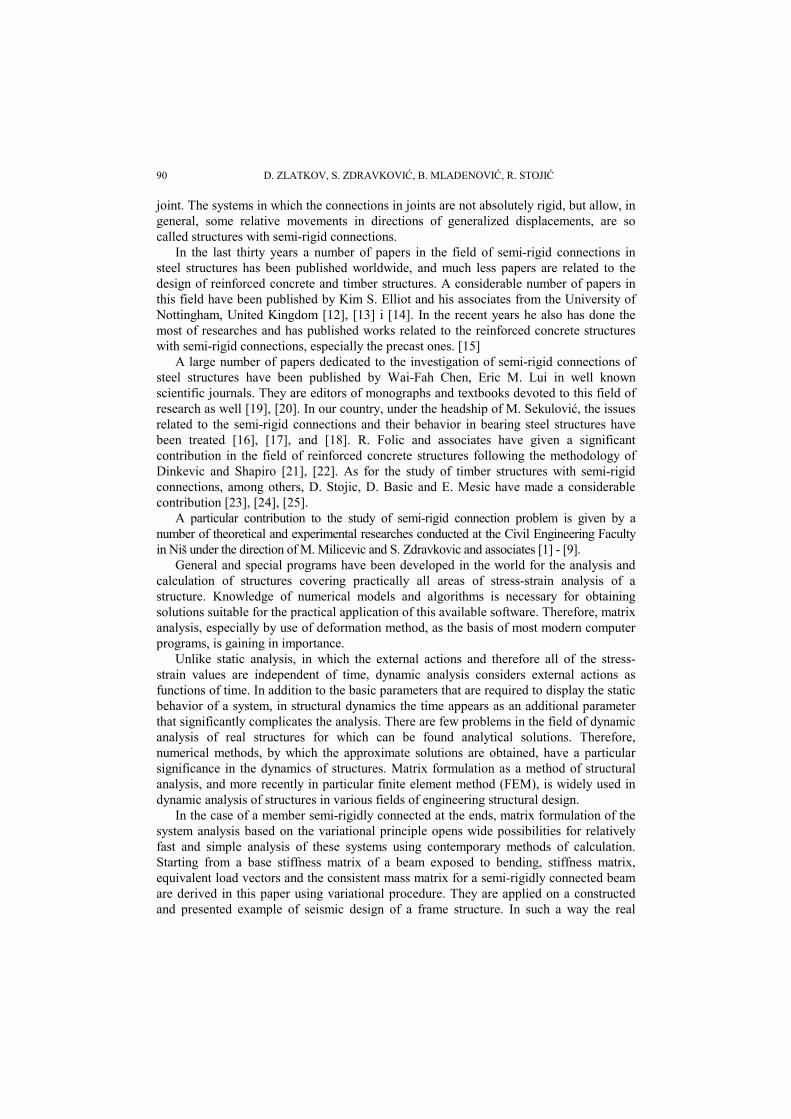
Fig.1 shows a beam of length l and constant cross section, which is exposed to bending in the plane xOy in local coordinate system. Moment of inertia of the beam cross-section is denoted as I and a material modulus of elasticity is E. Convention on the positive signs of displacements and forces is shown in Fig. 1.
Fig. 1. Generalized displacements and generalized forces at the ends of a beam
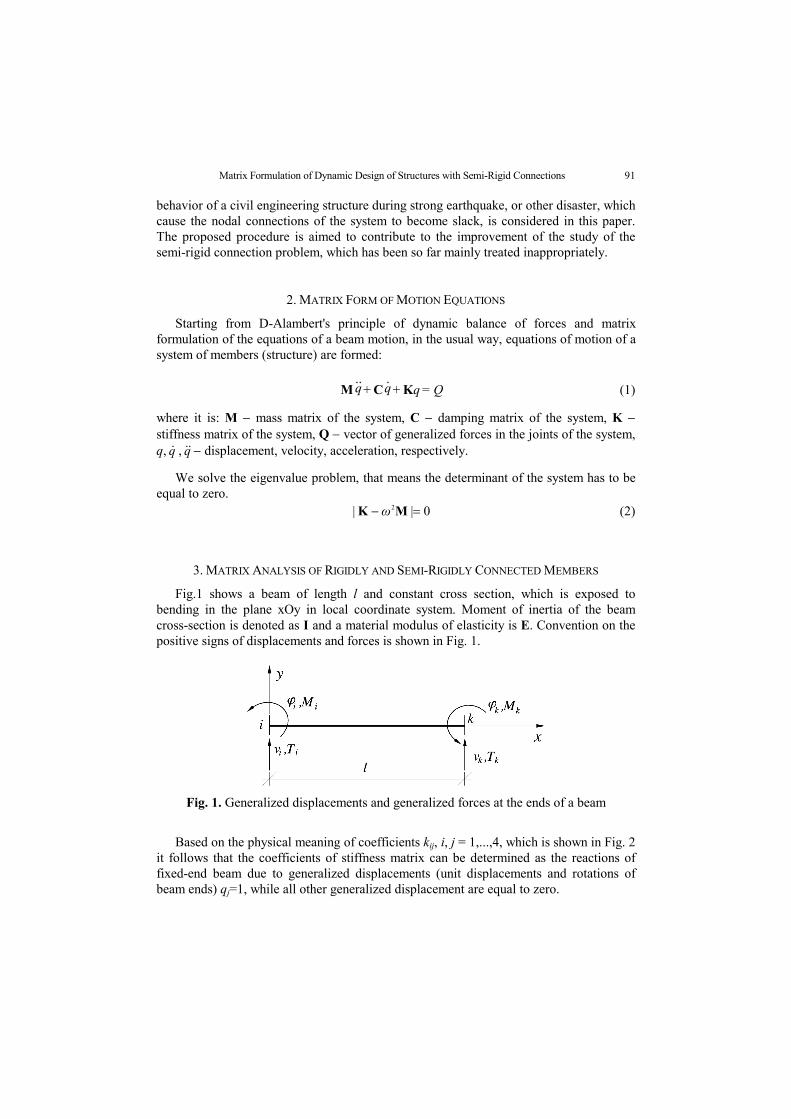
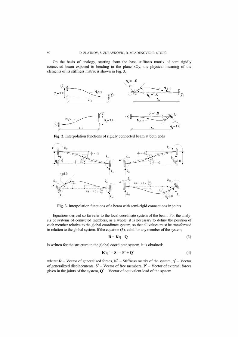
Based on the physical meaning of coefficients kij, i, j = 1,...,4, which is shown in Fig. 2 it follows that the coefficients of stiffness matrix can be determined as the reactions of fixed-end beam due to generalized displacements (unit displacements and rotations of beam ends) qj=1, while all other generalized displacement are equal to zero.
D. ZLATKOV, S. ZDRAVKOVIĆ, B. MLADENOVIĆ, R. STOJIĆ 92
On the basis of analogy, starting from the base stiffness matrix of semi-rigidly connected beam exposed to bending in the plane xOy, the physical meaning of the elements of its stiffness matrix is shown in Fig. 3.
Fig. 2. Interpolation functions of rigidly connected beam at both ends
Fig. 3. Interpolation functions of a beam with semi-rigid connections in joints
Equations derived so far refer to the local coordinate system of the beam. For the analy-sis of systems of connected members, as a whole, it is necessary to define the position of each member relative to the global coordinate system, so that all values must be transformed in relation to the global system. If the equation (3), valid for any member of the system,
QKqR = (3)
is written for the structure in the global coordinate system, it is obtained:
***** QPSqK +== (4)
where: R Vector of generalized forces, K* Stiffness matrix of the system, q* Vector of generalized displacements, S* Vector of free members, P* Vector of external forces given in the joints of the system, Q* Vector of equivalent load of the system.
Matrix Formulation of Dynamic Design of Structures with Semi-Rigid Connections 93
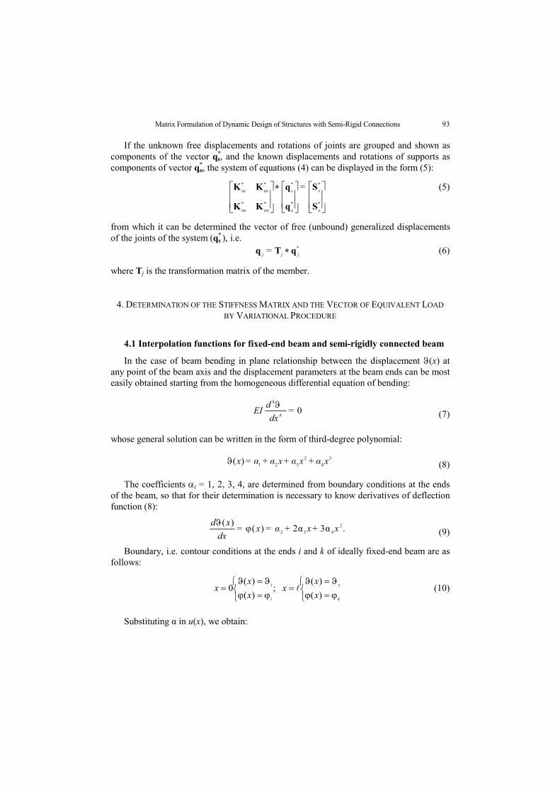
If the unknown free displacements and rotations of joints are grouped and shown as components of the vector q*
s, and the known displacements and rotations of supports as components of vector q*
o, the system of equations (4) can be displayed in the form (5):
*
*
*
*
*
oo
*
os
*
so
*
ss
o
s
o
s =
S
S
q
q
KK
KK (5)
from which it can be determined the vector of free (unbound) generalized displacements of the joints of the system (q*
s ), i.e. *
jjj = qTq (6)
where Tj is the transformation matrix of the member.
4. DETERMINATION OF THE STIFFNESS MATRIX AND THE VECTOR OF EQUIVALENT LOAD
BY VARIATIONAL PROCEDURE
4.1 Interpolation functions for fixed-end beam and semi-rigidly connected beam
In the case of beam bending in plane relationship between the displacement (x) at any point of the beam axis and the displacement parameters at the beam ends can be most easily obtained starting from the homogeneous differential equation of bending:
04
=dx
dEI
4
(7)
whose general solution can be written in the form of third-degree polynomial:
3
4
2
321)( xα+xα+xα+α=x (8)
The coefficients i = 1, 2, 3, 4, are determined from boundary conditions at the ends of the beam, so that for their determination is necessary to know derivatives of deflection function (8):
.3α2α)()( 2
432 x+x+α=x=dx
xd
(9)
Boundary, i.e. contour conditions at the ends i and k of ideally fixed-end beam are as follows:
k
x
i
i
x
xx
x
xx
)(
)( ;
)(
)(0 (10)
Substituting α in u(x), we obtain:
D. ZLATKOV, S. ZDRAVKOVIĆ, B. MLADENOVIĆ, R. STOJIĆ 94
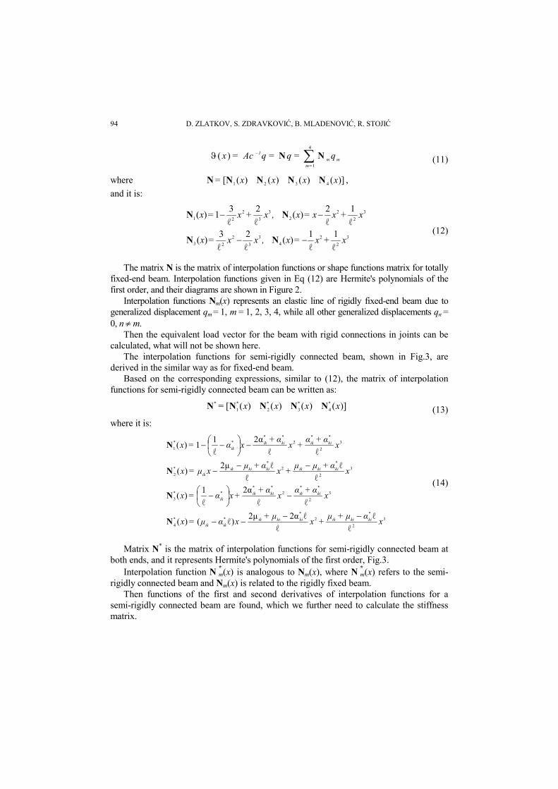
m=m
m
1 q=q=qAc=x 4
1
)( NN (11)
where ])()()()([ 4321 xxxx= NNNNN ,
and it is:
3
2
2
4
3
3
2
23
3
2
2
2
3
3
2
21
ℓ
1
ℓ
1)(
ℓ
2
ℓ
3)(
ℓ
1
ℓ
2)(
ℓ
2
ℓ
31)(
x+x=x,xx=x
x+xx=x,x+x=x
NN
NN
(12)
The matrix N is the matrix of interpolation functions or shape functions matrix for totally fixed-end beam. Interpolation functions given in Eq (12) are Hermite's polynomials of the first order, and their diagrams are shown in Figure 2.
Interpolation functions Nm(x) represents an elastic line of rigidly fixed-end beam due to generalized displacement qm = 1, m = 1, 2, 3, 4, while all other generalized displacements qn = 0, n m.
Then the equivalent load vector for the beam with rigid connections in joints can be calculated, what will not be shown here.
The interpolation functions for semi-rigidly connected beam, shown in Fig.3, are derived in the similar way as for fixed-end beam.
Based on the corresponding expressions, similar to (12), the matrix of interpolation functions for semi-rigidly connected beam can be written as:
])()()()([ *
4
*
3
*
2
*
1
* xxxx= NNNNN (13)
where it is:
3
2
*2
***
4
3
2
**2
****
3
3
2
*2
**
2
3
2
**2
****
1
ℓ
ℓ
ℓ
ℓ2α2μ)ℓ()(
ℓℓ
2α
ℓ
1)(
ℓ
ℓ
ℓ
ℓ2μ)(
ℓℓ
2α
ℓ
11)(
xαμ+μ
+xμ+
xαμ=x
xα+α
xα+
+xα=x
xα+μμ
+xα+μ
xμ=x
xα+α
+xα+
xα=x
kikiikkikiikikik
kiikkiikik
kikiikkikiikik
kiikkiikik
N
N
N
N
(14)
Matrix N* is the matrix of interpolation functions for semi-rigidly connected beam at both ends, and it represents Hermite's polynomials of the first order, Fig.3.
Interpolation function N *m(x) is analogous to Nm(x), where N *m(x) refers to the semi-rigidly connected beam and Nm(x) is related to the rigidly fixed beam.
Then functions of the first and second derivatives of interpolation functions for a semi-rigidly connected beam are found, which we further need to calculate the stiffness matrix.
Matrix Formulation of Dynamic Design of Structures with Semi-Rigid Connections 95
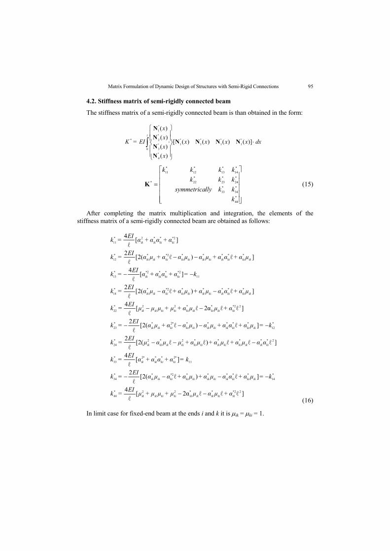
4.2. Stiffness matrix of semi-rigidly connected beam
The stiffness matrix of a semi-rigidly connected beam is than obtained in the form:
ℓ
0
"
1
"
1
"
1
"
1
"
4
"
3
"
2
"
1
* ])()()()([
)(
)(
)(
)(
dxxxxx
x
x
x
x
EI=K NNNN
N
N
N
N
*
44
*
34
*
33
*
24
*
23
*
22
*
14
*
13
*
12
*
11
*
k
kkllysymmetrica
kkk
kkkk
K (15)
After completing the matrix multiplication and integration, the elements of the stiffness matrix of a semi-rigidly connected beam are obtained as follows:
]ℓℓℓ2α[
ℓ
4
]ℓ)ℓ(2[ℓ
2
][ℓ
4
]ℓℓℓ)ℓℓ(2[ℓ
2
]ℓ)ℓ(2[ℓ
2
]ℓℓ2αℓ[ℓ
4
]ℓ)ℓ(2[ℓ
2
][ℓ
4
]ℓ)ℓ(2[ℓ
2
][ℓ
4
22***22*44
*14
*****2***34
11
*2***2*
33
2*****2*2*
24
*
12
******2**
23
22***22*22
*****2***14
11
2***2**
13
*****2***
12
2***2*
11
ikkiikikikkikiikik
ikkikiikkiikkikikiikik
kikiikik
kiikikkikiikkikikiikikik
ikkikiikkiikkikikiikik
kikikiikkikikiikik
ikkikiikkiikkikikiikik
kikiikik
ikkikiikkiikkikikiikik
kikiikik
α+μαμμ+μμ+μEI
=k
k=μα+ααμα+μα+αμαEI
=k
k=α+αα+αEI
=k
ααμα+μα+μα+μμαμEI
=k
k=μα+αα+μαμαα+μαEI
=k
α+μμα+μ+μμμEI
=k
μα+ααμα+μα+αμαEI
=k
k=α+αα+αEI
=k
μα+αα+μαμαα+μαEI
=k
α+αα+αEI
=k
(16)
In limit case for fixed-end beam at the ends i and k it is ik = ki = 1.
D. ZLATKOV, S. ZDRAVKOVIĆ, B. MLADENOVIĆ, R. STOJIĆ 96
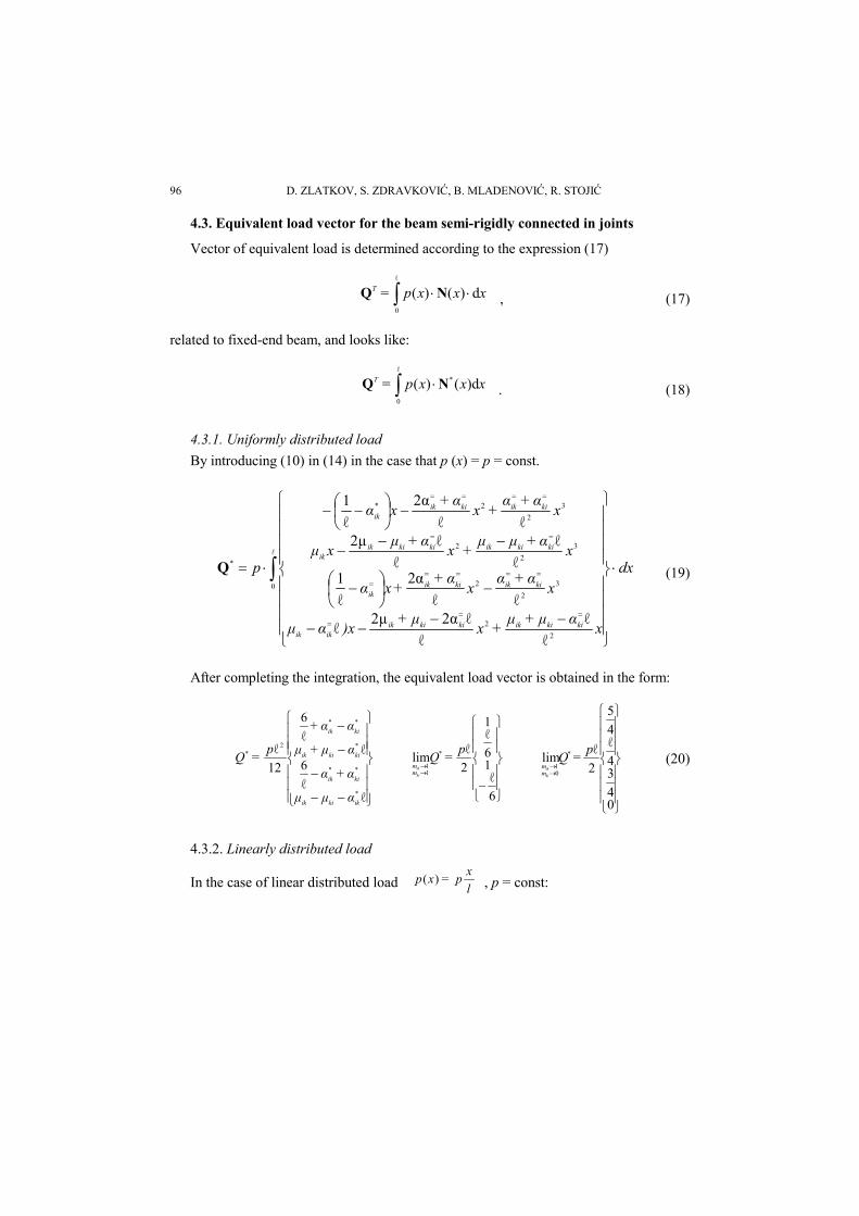
4.3. Equivalent load vector for the beam semi-rigidly connected in joints
Vector of equivalent load is determined according to the expression (17)
ℓ
0
d)()( xxxp=T NQ , (17)
related to fixed-end beam, and looks like:
ℓ
0
* )d()( xxxp=T NQ . (18)
4.3.1. Uniformly distributed load
By introducing (10) in (14) in the case that p (x) = p = const.
dx
xαμ+μ
+xμ+
)xαμ
xα+α
xα+
+xα
xα+μμ
+xα+μ
xμ
xα+α
+xα+
xα
p
kikiikkikiikikik
kiikkiikik
kikiikkikiikik
kiikkiikik
0
2
2
3
2
2
3
2
2
3
2
2*
*
ℓ
ℓ
ℓ
ℓ2α2μℓ
ℓℓ
2α
ℓ
1ℓ
ℓ
ℓ
ℓ2μℓℓ
2α
ℓ
1
Q (19)
After completing the integration, the equivalent load vector is obtained in the form:
ℓℓ
6ℓ
ℓ
6
12
ℓ
*
**
*
**
2*
ikkiik
kiik
kikiik
kiik
αμμ
α+α
αμ+μ
αα+
p=Q
6
ℓ16
ℓ1
2
ℓlim *
11
p=Q
ki
ikmm
04
34
ℓ4
5
2
ℓlim *
01
p=Q
ki
ikmm
(20)
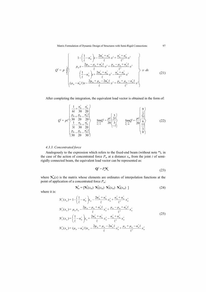
4.3.2. Linearly distributed load
In the case of linear distributed load l
xp=xp )( , p = const:
Matrix Formulation of Dynamic Design of Structures with Semi-Rigid Connections 97
ℓ
0
3
2
*2
**
3
2
**2
***
3
2
*2
*
3
2
**2
***
*
ℓ
ℓ
ℓ
ℓ2α2μ)ℓ(
ℓℓ
2α
ℓ
1ℓ
ℓ
ℓ
ℓ2μℓℓ
2α
ℓ
11
dxx
xαμ+μ
+xμ+
xαμ
xα+α
xα+
+xα
xα+μμ
+xα+μ
xμ
xα+α
+xα+
xα
p=Q
kikiikkikiikikik
kiikkiikik
kikiikkikiikik
kiikkiikik
(21)
After completing the integration, the equivalent load vector is obtained in the form of:
30
ℓ
2030
2030ℓ3
120
ℓ
2030
2030ℓ6
1
ℓ
*
*
*
**
2*
ikkiik
kiik
kikiik
kiik
αμμ
α+
α
αμ+
μ
αα+
p=Q
ℓ3
ℓ23
20
ℓlim *
11
p=Q
ki
ikmm
03
116
ℓ72
9
20
ℓlim *
01
p=Q
ki
ikmm
(22)
4.3.3. Concentrated force
Analogously to the expression which refers to the fixed-end beam (without note *), in the case of the action of concentrated force Pm at a distance xm from the joint i of semi-rigidly connected beam, the equivalent load vector can be represented as:
*
mm
T P= NQ (23)
where N*m(x) is the matrix whose elements are ordinates of interpolation functions at the
point of application of a concentrated force Pm:
N*m = [N*
1(xm) N*2(xm) N*
3(xm) N*4(xm) ] (24)
where it is:
3
2
*2
***
4
3
2
**2
****
3
3
2
*3
**
2
3
2
**2
****
1
ℓ
ℓ
ℓ
ℓ2α2μ)ℓ()(
ℓℓ
2α
ℓ
1)(
ℓ
ℓ
ℓ
ℓ2μ)(
ℓℓ
2α
ℓ
11)(
mkikiik
mkikiik
mikikm
mkiik
mkiik
mikm
mkikiik
mkikiik
mikm
mkiik
mkiik
mikm
xαμ+μ
+xμ+
xαμ=xN
xα+α
xα+
+xα=xN
xα+μμ
+xα+μ
xμ=xN
xα+α
+xα+
xα=xN
(25)
D. ZLATKOV, S. ZDRAVKOVIĆ, B. MLADENOVIĆ, R. STOJIĆ 98
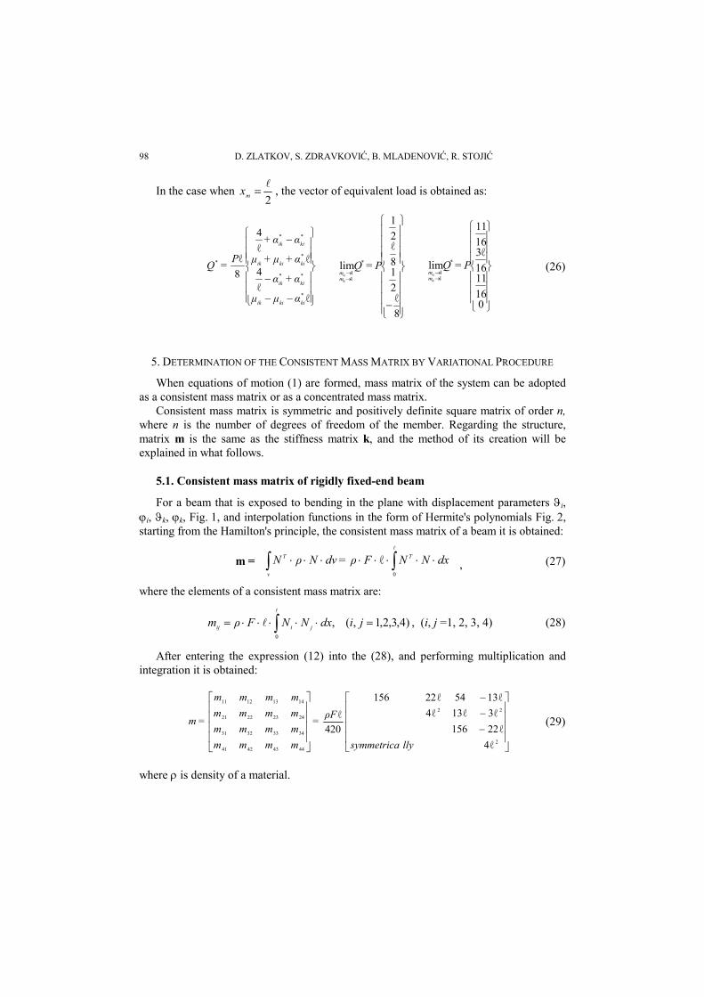
In the case when 2
mx , the vector of equivalent load is obtained as:
ℓℓ
4ℓ
ℓ
4
8
ℓ
*
**
*
**
*
kikiik
kiik
kikiik
kiik
αμμ
α+α
α+μ+μ
αα+
P=Q
8
ℓ2
18
ℓ2
1
lim *
11
P=Qik
ki
mm
016
1116
3ℓ16
11
lim *
11
P=Qik
ki
mm
(26)
5. DETERMINATION OF THE CONSISTENT MASS MATRIX BY VARIATIONAL PROCEDURE
When equations of motion (1) are formed, mass matrix of the system can be adopted as a consistent mass matrix or as a concentrated mass matrix.
Consistent mass matrix is symmetric and positively definite square matrix of order n, where n is the number of degrees of freedom of the member. Regarding the structure, matrix m is the same as the stiffness matrix k, and the method of its creation will be explained in what follows.
5.1. Consistent mass matrix of rigidly fixed-end beam
For a beam that is exposed to bending in the plane with displacement parameters i, i, k, k, Fig. 1, and interpolation functions in the form of Hermite's polynomials Fig. 2, starting from the Hamilton's principle, the consistent mass matrix of a beam it is obtained:
m =
0
ℓ dxNNFρ=dvNρN T
v
T
, (27)
where the elements of a consistent mass matrix are:
0
)4,3,2,1,( , jidxNNFρm jiij , (i, j =1, 2, 3, 4) (28)
After entering the expression (12) into the (28), and performing multiplication and integration it is obtained:
2
22
44434241
34333231
24232221
14131211
ℓ4
ℓ22156
ℓ3ℓ13ℓ4
ℓ1354ℓ22156
420
ℓ
llysymmetrica
ρF=
mmmm
mmmm
mmmm
mmmm
=m (29)
where is density of a material.

Matrix Formulation of Dynamic Design of Structures with Semi-Rigid Connections 99
5.2. Consistent mass matrix of semi-rigidly connected beam
Starting from the interpolation functions of semi-rigidly fixed-end beam, shown in Fig.3, the elements of the consistent mass matrix of such beam may be derived analogously to expressions (27) and (28) in the form:
4,...,1, ,)()(ρ *
0
** nmdxxNxNF nmmn
m (30)
introducing (14) in (30), after the multiplication and integration, it is obtained:
])3α(4α
4α3α3α4α(1421[14420
]3α)4α3α3α4()4([420
])3α(4α
)4α3α3α4α(2121[14420
])3α(4α
)4α3α3α4α(2114[21420
])6α4α(4α)7(70[420
])4α(3α
)4α3α3α4α(1414[21420
]8m)6()4([420
])6α4α(4α)42(28140[420
]8m)6()4([420
])6α4α(4α)28(42140[420
2**2
******
34
22******22*
24
2**2
******
23
2**2
******
14
2**22***
13
22**
******
12
2**2222*
44
2**22***
33
2**2222*
22
2**22***
11
kiikik
kikiikkikiikikikikkiik
kiikkikiikkikiikikikkiik
kiikki
kikiikkikiikikikkikiik
kiikik
kikiikkikiikikikikkiik
kiikkiikkiik
kikiik
kikiikkikiikikikkikiik
ikikikkikiikkikiik
kiikkiikkiik
kikikiikkiikkikiik
kiikkiikkiik
α+
+)m+mmm+αmmρF
=m
α+mm+m+mαmmρF
=m
α
mmm+m+αm+mρF
=m
α
mm+m+mαmmρF
=m
α+α+αρF
=m
α
m+m+mmαm+mρF
=m
ααm+mm+α+m+mρF
=m
α++ααρF
=m
ααmmm+α+m+mρF
=m
α++αα+ρF
=m
(31)
and mass matrix of the semi-rigidly fixed-end beam can be displayed in the form:
*
44
*
43
*
42
*
41
*
34
*
33
*
32
*
31
*
24
*
23
*
22
*
21
*14
*13
*12
*11
*
mmmm
mmmm
mmmm
mmmm
=m (32)
In the limit case, for the member of type k it is obtained:

D. ZLATKOV, S. ZDRAVKOVIĆ, B. MLADENOVIĆ, R. STOJIĆ 100
m=
llysymmetrica
ρF=
mkimik
2
22
*
11
ℓ4
ℓ22156
ℓ3ℓ13ℓ4
ℓ1354ℓ22156
420
ℓlim m
(33)
which is consistent with (29).
This mass matrix can be incorporated into the ready-made software packages and used for dynamic and seismic analysis of structures.
6. EXAMPLE OF DYNAMIC CALCULATION OF A STRUCTURE WITH SEMI–RIGID CONNECTIONS
Matrix formulation as a method of structural analysis, and more recently in particular finite element method (FEM), is widely used in dynamic analysis of structures in various fields of engineering structural design.
For the frame shown in Fig. 4 for different levels of rigidity of the members in the joints (cases a) to f)) it is calculated: the circular frequencies and the periods of free hori-zontal oscillations of the frame, and the horizontal seismic forces, according to [10] and the maximum horizontal displacement of the frame for seismic load calculated according to the Article 16. The frame is treated as a reinforced concrete one, with cross sections de-fined by dimensioning of the structure according to influences due to uniformly distrib-uted load q = 20 kN/m and concentrated force 40 kN at joint 2 (Fig.4a), providing that failure appears in reinforcement. The following dimensions of cross sections were ob-tained: members 1 and 2 are b/h=50/115 cm, member 3 is b/h=50/90 cm. Modulus of elasticity of concrete was determined according to Regulation BAB 87 and for adopted concrete MB 30 it is E = 3150x104 kN/m2, and the comparative bending stiffness of the frame (member 3) is EI = 1746937.5 kNm2. The weight of the structure is Q=q l=20•25 = 500kN. Circular frequency of the frame is determined according to the formula:
i
1
i
1
i
QEIu
gEI=
mu=ω
1 (34)
Where it is: i circular frequency of free oscillations of the frames (i = a to f) g acceleration due to gravity ui
1 horizontal displacement of the mass m of the frames (i = a) to f)
Fig. 4. a) The structure and load; b) Member and joint labels; c) Generalized displacements.

Matrix Formulation of Dynamic Design of Structures with Semi-Rigid Connections 101
For the numerical example shown in Fig. 4, considering different levels of rigidity of connections in joints of the frame, discretization of the system was made, and the stiffness matrices and equivalent load vectors of members are determined, the system stiffness matrix and the vector of free members are defined as well. The components of displacement vectors and internal forces at the ends of members are computed. For different levels of rigidity of connections in the joints, shown in Fig. 4b and Table 1, several numerical quantities are calculated and given in Table 2: displacements EIu1 [m], the circular frequency ω [s-1], the period T [s], the dynamic coefficient according to the Code [10], kd = 0.7/T, and adopted coefficient kd, designed seismic forces S [kN] and maximal displacement u1,5 [m].
Table 1.
Joint The level of rigidity of connection a b c d e f 1 ζ 1,0 0,5 0,5 1,0 1,0 0 2 ζ 1,0 0,5 0,5 0 1,0 0 3 η 1,0 1,0 0,5 1,0 0 1,0 4 η 1,0 1,0 0,5 0 0 0
This example of seismic design of a system with semi-rigid connections, taking into
account different levels of rigidity of connections by use of corresponding stiffness matrices, was analyzed using SASS software. Design horizontal seismic forces are calculated according to the Code [10], i.e. total horizontal seismic force is calculated according to the formula:
QKKKKKQS pds0 . (35)
The coefficients K are defined in the Code, and in this case were adopted as: K0 = 1.0 (the first category of building); Ks = 0.1 (IX degree MCS-64 scale); Kp = 1.0 Kd = 0.7/T; 1.0 Kd 0.47 (the second soil category).
Table 2.
EIu1[m] [s1] T [s] kd = 0,7/T kd, adopted S[kN] us1[m]
a 149,00 11,220 0,539 1,251 1,000 50,00 0,0077 b 229,91 9,036 0,694 1,007 1,000 50,00 0,0120 c 383,26 6,998 0,897 0,780 0,780 39,00 0,0156 d 402,25 6,830 0,919 0,760 0,760 38,00 0,0159 e 505,70 6,093 1,030 0,679 0,679 33,95 0,0179 f 633,27 5,445 1,153 0,607 0,607 30,35 0,0201
The maximal frame displacement (Fig. 4) for the design seismic forces determined by the Theory of elasticity, according to Article 16 of the Code, amounts u1,5 (1) ≤ H/600, where H is the height of the building in cm.

D. ZLATKOV, S. ZDRAVKOVIĆ, B. MLADENOVIĆ, R. STOJIĆ 102
7. CONCLUSION
At the optimum dimensioning of the real structures there is a need elasticity of joint connections to be taken in design, i.e. real stiffness of the connections in joints. The constructions with elastic, semi-rigid, connections are those in which the joint connections are not absolutely rigid, but allow generalized movements in all directions. It was observed that the level of rigidity is particularly important in the case of prefabricated structures, because even a small degree of fixing of prefabricated connections affects the redistribution of static and deformation influences, as well as the basic dynamic characteristics of the structure. This fact is taken into account very little, or not at all, in current engineering practice in the design of structures. If the influence of rigidity of semi-rigid connections in the design is underestimated and they are treated as pinned, this have a negative impact on construction economy. However, if unreal high level of rigidity is assumed, the results are not on the side of safety, which may adversely affect the carrying capacity, durability and structural stability.
Common European regulations, Eurocodes for construction (in particular Eurocode 3, Eurocode 4, Eurocode 8), devote due attention to the design and construction of the systems with semi-rigid connections.
In the case of the beam semi-rigidly connected at the both ends, the variational procedure, based on the stationary of functional of potential energy of the beam, and matrix formulation of the dynamic design is used. Determined elements of the interpolation function matrix (shape function matrix) are Hermite's polynomials of the first order. The stiffness matrix and equivalent load vectors are determined too.
A computer program is created for calculation of defined elements of the stiffness matrix , which enables calculation of the stiffness matrix elements for various levels of rigidity of connections, as well as software (SASS) for dynamic and seismic design according to the Code on Technical Standards for the Construction of High Rise Buildings in Seismic Areas. Available software packages for dynamic design of structures also can be adapted for the calculation of structures with semi-rigid connections by introducing corresponding matrices. Application of the software SASS on structures with semi-rigid connections is illustrated by use of numerical example. Bending moments due to dynamic (seismic) load, the basic dynamic characteristics, displacements and seismic forces are calculated in presented numerical example. The results show that there are significant differences depending on the level of rigidity of connections. This clearly indicates that the real stiffness of the connections must be properly taken into account by design and calculation of all engineering structures.
REFERENCES
1. S. Zdravković, M. Milićević, D. Veličković, "Dynamical and experimental testing of systems with semi-rigid connections", Scientific Journal FACTA UNIVERSITATIS, Series: Architecture and Civil Engineering, University of Niš, Vol.1, No 3, pp 289-304, 1995.
2. M. Milićević, S. Zdravković, D. Zlatkov, B. Konstadinov, "Matrix formulation of design and testing of structures with semi-rigid conection", Structural Engineers World Congress, july 19-23. 1998, San Francisco, California, pp. 266, 1998.
3. M. Milićević, S. Zdravković, D. Veličković, "Analysis of linear systems with semi-rigid connections", Scientific Journal FACTA UNIVERSITATIS, Series: Architecture and Civil Engineering, University of Niš, Vol.1, No 2, pp 125-144, 1995.
Matrix Formulation of Dynamic Design of Structures with Semi-Rigid Connections 103
4. M. Milićević, S. Zdravković, D. Zlatkov, B. Mladenovic, "Dynamic analysis and testing of structures with semi-rigid conection", Workshop Computational Structural Dynamics, IZIIS Skopje, Macedonia, Balcema, Rotherdam, pp , Februar 2001.
5. D. Zlatkov, " Analysis of frames with semi-rigid connections of members in joints ", MA thesis, University of Niš, Faculty of Civil Engineering and Architecture, 1998. (in Serbian)
6. S. Zdravković, D. Zlatkov, B. Mladenović, M.Mijalković, "Seismic analysis of plane linear systems with semi-rigid conection", Earthquake resistant engineering structures, VII World Conference, Limasol, Cyprus, Maj 2009. Wessex institute of tehnology, UK, Editors: M.Procas, C.A.Brebbia, P.Komodomos, pp. 105-115.
7. S. Zdravković, M. Milićević, R. Folić, D. Zlatkov, "Significance and part of elastic connections of member with joints in earthquake engineering". Eleventh world conference on earthquake engineering, 11WCEE, Acapulco, Mexico, June 23-28., pp. 626, 1996.
8. M. Milićević, S. Zdravković, R. Folić, D. Zlatkov, "Theoretical basis and dynamic design of systems with semi-rigid connections of members with joints". Eleventh world conference on earthquake engineering, 11WCEE, Acapulco, Mexico, June 23-28., pp. 623, 1996.
9. M. Milićević, S. Zdravković, The impact and importance of semi-rigid connections in structural design, 20 Yugoslav Congress of Theoretical and Applied Mechanics, 19-21 August 1993, Kragujevac, pp. 212-215. (in Serbian)
10. Code on Technical Standards for the Construction of High Rise Buildings in Seismic Areas (Official Gazette SFRY No.31. from 5 June 1981), Beograd, 1981.
11. S.W. Jones, P.A. Kirby, D.A. Nehercot, The analysis of structures with semi-rigid connections. A state of the art. Department of civil engineering, University of Sheffield. 1982.
12. Elliott, K.S., Ferreira, M. and El Debs, M.,. Analysis of multi-storey precast frames considering beam-column connections with semi-rigid behaviour. In: FIB Symposium- Keep Concrete Attractive, Budapest. Lausanne: International Federation for Structural Concrete, 2005, pp. 496-501.
13. Ferriera, M.A., El Debs, M.K. and Elliott, K.S., 2003. Analysis of Multistory Precast Frames with Semi-Rigid Connections. In: Brazilian Conference on Concrete, IBRACON 45th Brazilian Concrete Congress, Brazilian Concrete Institute - IBRACON, Vitoria, Brazil. 2003,pp. 120-132.
14. Ferriera, M.A., El Debs, M.K. and Elliott, K.S., Theoretical Model for Design of Semi-Rigid Connections in Precast Concrete Structure. In: 44th Brazilian Concrete Congress, IBRACON Brazilian Concrete Institute, Belo Horizonte, Brazil. 2002, pp. 100-116
15. Elliott, K.,.at all, Structural connections for precast concrete buildings, 1. International fedration for structural concrete, 2008.
16. M. Sekulović at all, Nonlinear analysis of frames with flexible connections, Computer and structures, 79, 2001, p.p.1097-1107.
17. M. Sekulović at all, Dynamic analysis of steel frames with flexible connections, Computer and structures, 80, Iss.11, 2002, p.p.935-955.
18. M. Sekulović at all, Contribution to transient analysis of inelastik steel frames with semi-rigid connections, Engineering structures 30, 2008, p.p. 976-989.
19. W.F.Chen, E.M. Lui, Principles of structural design, Taylor and Francis, 2006. 20. W.F.Chen, J.Goto, J.Y.R. Liew, Stability design of semi-rigid frames, 2007. 21. R. Folic, D. Zenunovic, Durability design of concrete sttructures-Part 2: Modeling and structural
assesment, The Scientific Journal Facta Universitatis, Series: Architecture and Civil Engineering, University of Niš, Vol.8, No 1, 2010, pp 45-66.
22. R. Folic, Links and connections of precast reinforced buildings, Precast civil engineering structures, Ekonomika, Belgrade, 1988. 117-167. (in Serbian)
23. D. Bašić, D. Stojić, E. Mešić, Flexibile joint connection in structures: methods of computations and effects facta universitatis, Univesity of Niš, No 1,1994, p. 35-45
24. D. Bašić, E.Mešić, D. Stojić, Damping distribution over the Flexibile connection in the frame structures, The Scientific Journal Facta Universitatis, Series: Architecture and Civil Engineering, University of Niš, Vol.1, No 2, 1995, pp 145-151.
25. D. Bašić, D. Stojić, E. Mešić, Matrix analysis of structures with deformabile nodal connections, Monography: Modeling design and testing of structures. Faculty of Civil engineering in Niš, 1993, 41-67. (in Serbian)
26. R. Zandonini, P. Zanon, Semi-rigid and flexibil connections- An experimental investigation, Proceedings of the international conference on steel structures, Budva, 1986..

D. ZLATKOV, S. ZDRAVKOVIĆ, B. MLADENOVIĆ, R. STOJIĆ 104
MATRIČNA FORMULACIJA DINAMIČKOG PRORAČUNA KONSTRUKCIJA SA POLUKRUTIM VEZAMA
Dragan Zlatkov, Slavko Zdravković, Biljana Mladenović, Radoslav Stojić
U konstrukcije sa polukrutim vezama ubrajaju se sistemi kod kojih veze štapova u čvorovima nisu apsolutno krute, već dozvoljavaju, u opštem slučaju, izvestan stepen relativne pomerljivosti u pravcima generalisanih pomeranja. U današnjoj inženjerskoj praksi pri projektovanju konstrukcija vrlo se malo, ili ni malo, o tome vodi računa. Ukoliko je uticaj polukrutih veza potcenjen a one se u proračunu tretiraju kao zglobne, to se negativno odražava na ekonomičnost konstrukcije, a ukoliko je precenjen rezultati proračuna nisu na strani sigurnosti što se odražava na nosivost, trajnost i stabilnost, posebno kod montažnih konstrukcija. Evrokodovi ovim konstrukcijama posvećuju dužnu pažnju. Matrična formulacija analize sistema sa polukrutim vezama štapova otvara široke mogućnosti za relativno jednostavan i brz proračun konstrukcija uz primenu elektronskih računara, što je pokazano na primerima seizmičkog proračuna. U radu su date interpolacione funkcije, matrice krutosti i vektor ekvivalentnog opterećenja, kao i konzistentne matrice masa za sisteme sa krutim i polukrutim vezama štapova u čvorovima.
Key words: matrična formulacija, polukrute veze, konstrukcija, kompjuterski program, dinamički proračun.
Related Documents