Copyright © Artila Electronics Co., Ltd. All Rights Reserved. Matrix-752 Linux-Ready Cortex-A7 Industrial IoT Gateway Hardware Guide Version: 1.0 2020 JUNE

Welcome message from author
This document is posted to help you gain knowledge. Please leave a comment to let me know what you think about it! Share it to your friends and learn new things together.
Transcript

Copyright © Artila Electronics Co., Ltd. All Rights Reserved.
Matrix-752
Linux-Ready Cortex-A7 Industrial
IoT Gateway
Hardware Guide
Version: 1.0
2020 JUNE

Matrix-752 Hardware Guide
ARTILA 2
Trademarks
The Artila logo is a registered trademark of Artila Inc. All other trademarks or
registered marks in this manual belong to their respective manufacturers.
Disclaimer
Information in this document is subject to change without notice and does not
represent a commitment on the part of Artila.
Artila provides this document as is, without warranty of any kind, either expressed
or implied, including, but not limited to its particular purpose. Artila reserves the
right to make improvements and/or changes to this manual, or to the products
and/or the programs described in this manual, at any time.
Information provided in this manual is intended to be accurate and reliable.
However, Artila assumes no responsibility for its use, or for any infringements on
the rights of third parties that may result from its use.
This product might include unintentional technical or typographical errors.
Changes are periodically made to the information herein to correct such errors,
and these changes are incorporated into new editions of the publication.
FCC AND IC INFORMATION:
This Class A digital apparatus complies with Part 15 of the FCC rules and with
Canadian ICES-003
Operation is subject to the following two conditions:
1. This device may not cause interference and
2. This device must accept any interference. Including interference that may
cause undesired operation of the device.
Matrix-752 Hardware Guide
ARTILA 3
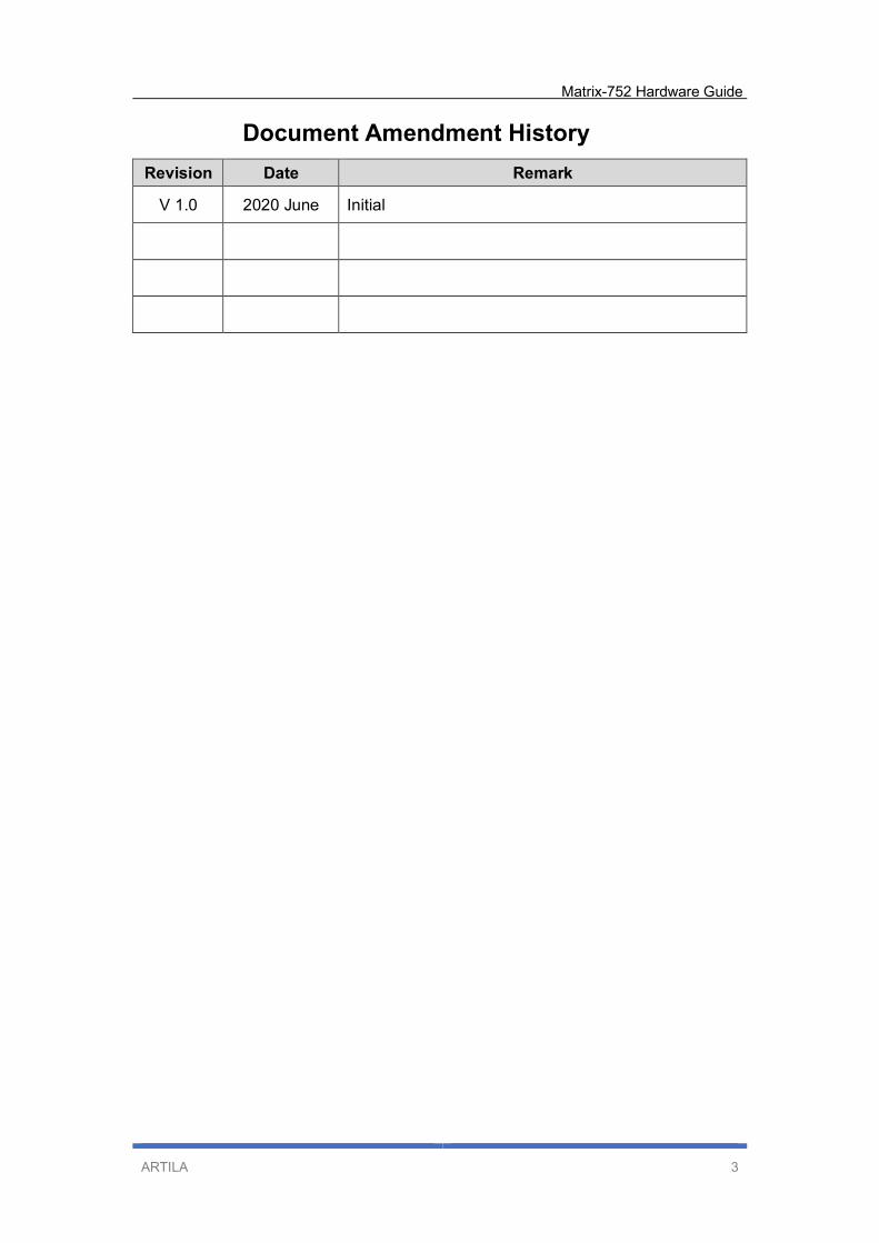
Document Amendment History
Revision Date Remark
V 1.0 2020 June Initial

Matrix-752 Hardware Guide
ARTILA 4
Table of Contents
1. Introduction .................................................................................................... 5
1.1 Features .................................................................................................. 5
1.2 Specifications (Hardware)........................................................................ 5
1.3 Specifications (Software) ......................................................................... 7
1.4 Packing List ............................................................................................. 8
1.5 Optional Accessory.................................................................................. 8
1.6 Optional Communication Module ............................................................. 8
2. Layout ............................................................................................................. 9
2.1 Connector & LED Indicator ...................................................................... 9
2.2 Dimension ............................................................................................... 10
3. Pin Assignment and Definitions .................................................................... 11
3.1 Multi-function Reset Button ...................................................................... 11
3.2 LED Indicators ......................................................................................... 12
3.3 Ethernet LAN Port ................................................................................... 13
3.4 Power Connector ..................................................................................... 14
3.5 USB OTG Port ......................................................................................... 14
3.6 Serial Port ............................................................................................... 15
3.7 CAN Bus Port .......................................................................................... 17
3.8 Digital Input ............................................................................................. 18
3.9 Digital Out ............................................................................................... 19
3.10 Serial Console Port.................................................................................. 20
3.11 External Battery connection ..................................................................... 21
3.12 SD card Socket ....................................................................................... 21
3.13 miniPCIe Slot........................................................................................... 22
3.14 Micro-SIM card socket ............................................................................. 22

Matrix-752 Hardware Guide
ARTILA 5
1. Introduction
Matrix-752 based on arm Cortex-A7, is a Linux-ready IoT gateway with highly
integrated and low power consumption. Matrix-752 provides an ideal building block
that easily integrates with a wide range of target markets, such as industrial control,
automation, mobile gateway and other applications.
1.1 Features
NXP iMX6ULL 800MHz Cortex-A7 Processor
Linux kernel 5.4.x and file system
Support Toolchain: gcc 9.3.0 + glibc 2.31
512MB LvDDR3 SDRAM
Two 10/100Mbps Ethernet port
One USB OTG port
One RS-485 / RS-232 port & One RS-232 port
One CAN port
Two channels Digital Input
Two channels Digital out
One micro-SD socket
One full size miniPCIe socket inside
One micro-SIM socket
Two SMA-type Antenna holes reserved
+9 to +48VDC power input
Ultra-low power consumption
Wall-mounting, Optional DIN RAIL mounting adaptor
1.2 Specifications (Hardware)
CPU / Memory
• CPU: NXP iMX6ULL Cortex-A7 MPCore, up to 800MHz
• SDRAM: 512MB, LvDDR3
Network Interface
• Type: 2 x 10/100Mbps Ethernet
• Connector Type: RJ45 (with LED indicator)
USB Interface
• 1 x USB OTG Port
• Micro-USB connector

Matrix-752 Hardware Guide
ARTILA 6
TTY (Serial) Ports
• 1 x RS-485 or RS-232 Port
• 1 x RS-232 Port
• Direction Control (RS-485): Auto, by software
• Connector: Terminal block
• RS-485 Signal: Data+, Data-
• RS-232 Signal: TX, RX
TTY (Serial) Port Parameters
• Baud Rate: Up to 921.6Kbps
• Parity: None, Even, Odd, Mark, Space
• Data Bits: 5, 6, 7, 8
• Stop Bits: 1, 1.5, 2
• Flow Control: RTS / CTS, XON / XOFF, None
CAN Bus Ports
• 1 x CAN Bus 2.0 A/B compliant ports
• Speed: Up to 1Mbps
• Isolation: 2500Vrms
Digital Input
• 2 x Digital Input Channels
• Isolation Protection: 2500Vrms (Photo Coupler)
• Logical High: 5~24VDC
• Logical Low: 0~1.5VDC
Digital Output
• 2 x Digital Output Channels (Solid State Relay)
• Solid State Relay: Normal Open (NO) Type
• Contact Rating: [email protected]
Console / Debug Ports
• Serial console port
• 4PIN Box header (inside the box)
Matrix-752 Hardware Guide
ARTILA 7
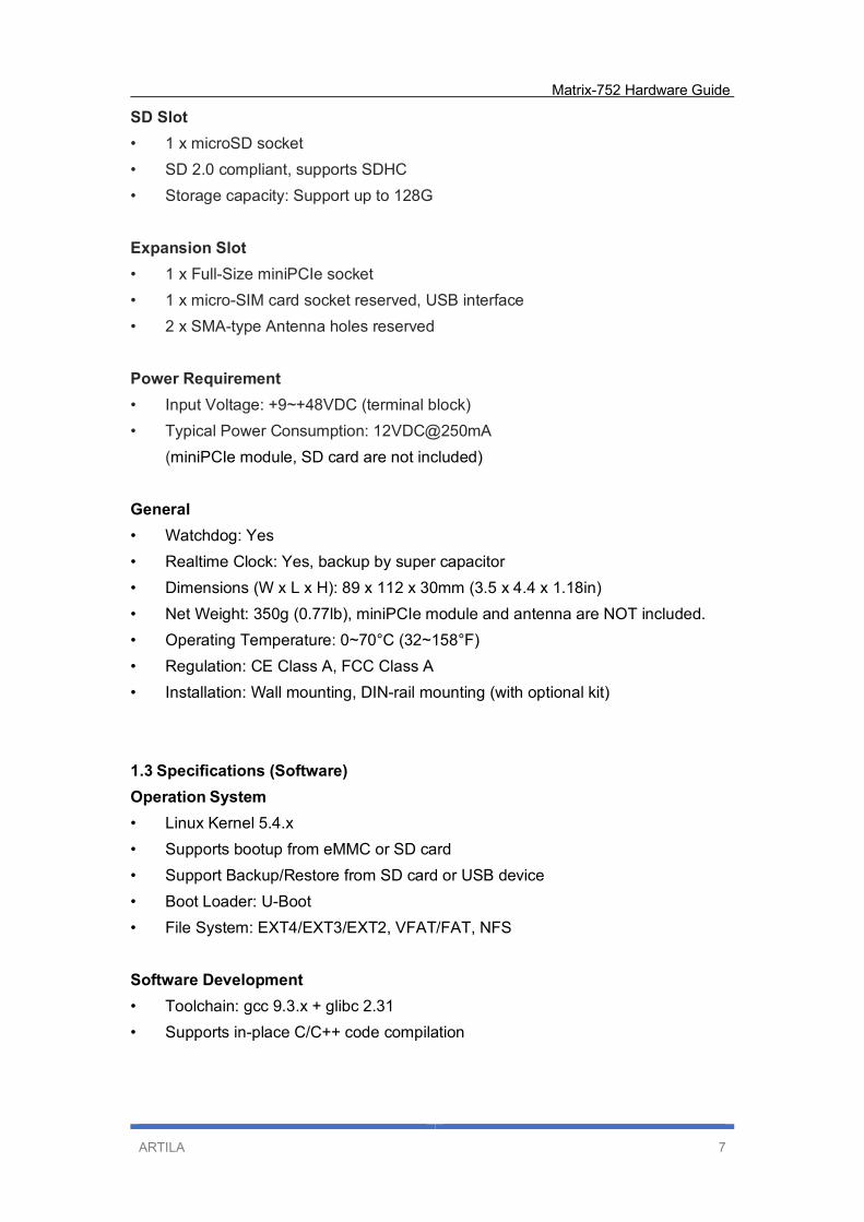
SD Slot
• 1 x microSD socket
• SD 2.0 compliant, supports SDHC
• Storage capacity: Support up to 128G
Expansion Slot
• 1 x Full-Size miniPCIe socket
• 1 x micro-SIM card socket reserved, USB interface
• 2 x SMA-type Antenna holes reserved
Power Requirement
• Input Voltage: +9~+48VDC (terminal block)
• Typical Power Consumption: 12VDC@250mA
(miniPCIe module, SD card are not included)
General
• Watchdog: Yes
• Realtime Clock: Yes, backup by super capacitor
• Dimensions (W x L x H): 89 x 112 x 30mm (3.5 x 4.4 x 1.18in)
• Net Weight: 350g (0.77lb), miniPCIe module and antenna are NOT included.
• Operating Temperature: 0~70°C (32~158°F)
• Regulation: CE Class A, FCC Class A
• Installation: Wall mounting, DIN-rail mounting (with optional kit)
1.3 Specifications (Software)
Operation System
• Linux Kernel 5.4.x
• Supports bootup from eMMC or SD card
• Support Backup/Restore from SD card or USB device
• Boot Loader: U-Boot
• File System: EXT4/EXT3/EXT2, VFAT/FAT, NFS
Software Development
• Toolchain: gcc 9.3.x + glibc 2.31
• Supports in-place C/C++ code compilation
Matrix-752 Hardware Guide
ARTILA 8
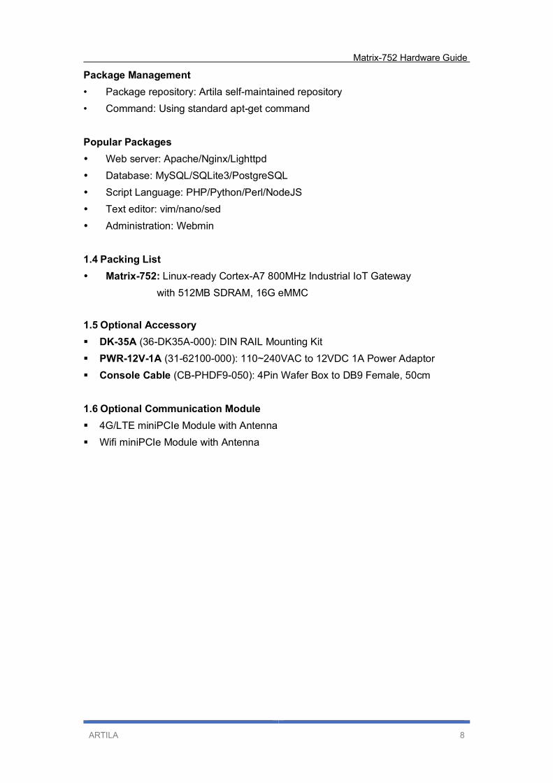
Package Management
• Package repository: Artila self-maintained repository
• Command: Using standard apt-get command
Popular Packages
Web server: Apache/Nginx/Lighttpd
Database: MySQL/SQLite3/PostgreSQL
Script Language: PHP/Python/Perl/NodeJS
Text editor: vim/nano/sed
Administration: Webmin
1.4 Packing List
Matrix-752: Linux-ready Cortex-A7 800MHz Industrial IoT Gateway
with 512MB SDRAM, 16G eMMC
1.5 Optional Accessory
DK-35A (36-DK35A-000): DIN RAIL Mounting Kit
PWR-12V-1A (31-62100-000): 110~240VAC to 12VDC 1A Power Adaptor
Console Cable (CB-PHDF9-050): 4Pin Wafer Box to DB9 Female, 50cm
1.6 Optional Communication Module
4G/LTE miniPCIe Module with Antenna
Wifi miniPCIe Module with Antenna
Matrix-752 Hardware Guide
ARTILA 9
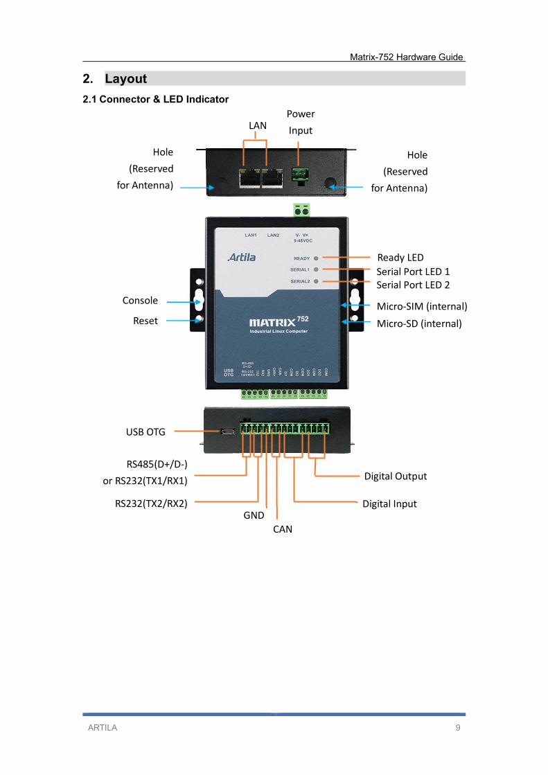
2. Layout
2.1 Connector & LED Indicator
RS485(D+/D-)
or RS232(TX1/RX1)
USB OTG
CAN
Digital Output
Ready LED
Serial Port LED 1
Serial Port LED 2
Micro-SD (internal)
Micro-SIM (internal) Console
Power
Input LAN
Hole
(Reserved
for Antenna)
Hole
(Reserved
for Antenna)
Reset
RS232(TX2/RX2) Digital Input GND
Matrix-752 Hardware Guide
ARTILA 10
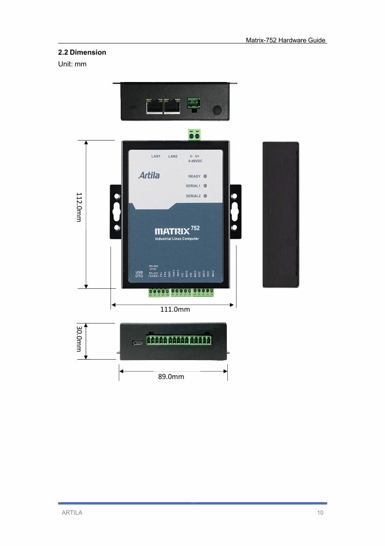
2.2 Dimension
Unit: mm
11
2.0
mm
3
0.0
mm
89.0mm
111.0mm
Matrix-752 Hardware Guide
ARTILA 11
3. Pin Assignment and Definitions
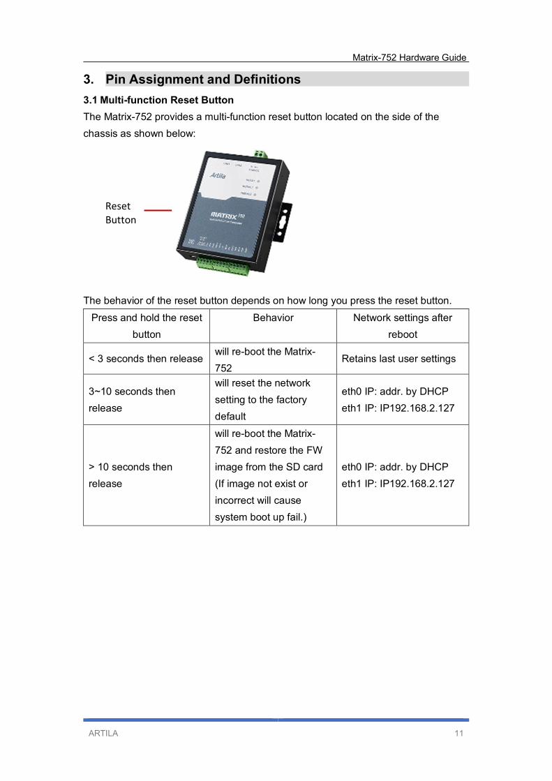
3.1 Multi-function Reset Button
The Matrix-752 provides a multi-function reset button located on the side of the
chassis as shown below:
The behavior of the reset button depends on how long you press the reset button.
Press and hold the reset
button
Behavior Network settings after
reboot
< 3 seconds then release will re-boot the Matrix-
752 Retains last user settings
3~10 seconds then
release
will reset the network
setting to the factory
default
eth0 IP: addr. by DHCP
eth1 IP: IP192.168.2.127
> 10 seconds then
release
will re-boot the Matrix-
752 and restore the FW
image from the SD card
(If image not exist or
incorrect will cause
system boot up fail.)
eth0 IP: addr. by DHCP
eth1 IP: IP192.168.2.127
Reset
Button
Matrix-752 Hardware Guide
ARTILA 12
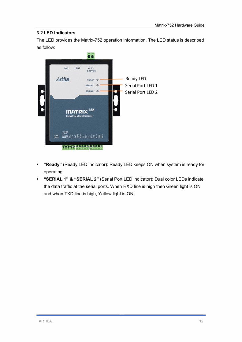
3.2 LED Indicators
The LED provides the Matrix-752 operation information. The LED status is described
as follow:
“Ready” (Ready LED indicator): Ready LED keeps ON when system is ready for
operating.
“SERIAL 1” & “SERIAL 2” (Serial Port LED indicator): Dual color LEDs indicate
the data traffic at the serial ports. When RXD line is high then Green light is ON
and when TXD line is high, Yellow light is ON.
Ready LED
Serial Port LED 1
Serial Port LED 2
Matrix-752 Hardware Guide
ARTILA 13
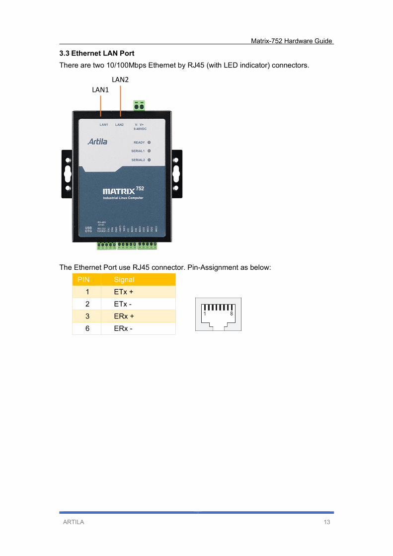
3.3 Ethernet LAN Port
There are two 10/100Mbps Ethernet by RJ45 (with LED indicator) connectors.
The Ethernet Port use RJ45 connector. Pin-Assignment as below:
PIN Signal
1 ETx +
2 ETx -
3 ERx +
6 ERx -
LAN1 LAN2
Matrix-752 Hardware Guide
ARTILA 14
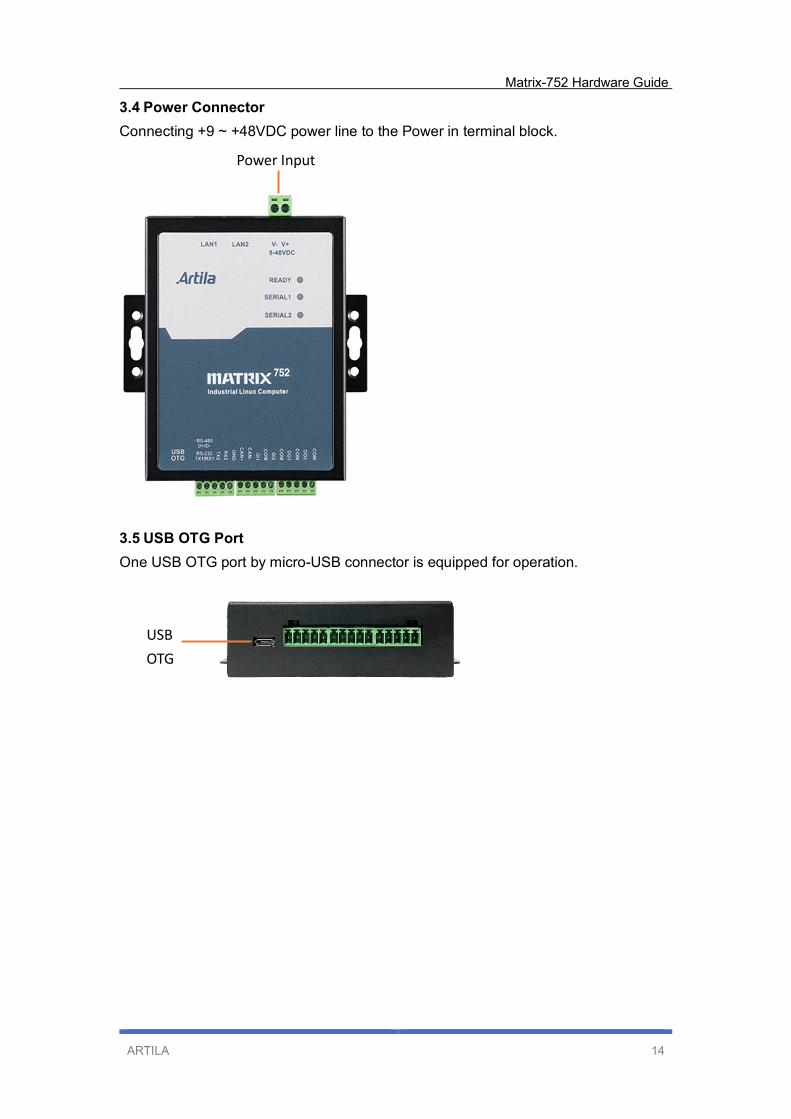
3.4 Power Connector
Connecting +9 ~ +48VDC power line to the Power in terminal block.
3.5 USB OTG Port
One USB OTG port by micro-USB connector is equipped for operation.
USB
OTG
Power Input

Matrix-752 Hardware Guide
ARTILA 15
3.6 Serial Port
The Matrix-752 has two serial ports:
One RS-485/RS-232 ports, Default setting is RS-485.
One RS-232 port (TX/RX)
RS-485 is designed without isolation that automatically direction controlled via
software
The pin assignment is shown as following table:
Port No. Pin1 Pin2 Pin3 Pin4 Pin5
Serial Port 1 RS-485 D+ D- -- -- GND
RS-232 (1) TX1 RX1 -- -- GND
Serial Port 2 RS-232 (2) -- -- TX2 RX2 GND
Enable/Disable Termination resistor for RS-485 (JP4)
The Matrix-752 provides on-board 120Ohm termination resistor for each RS-485
port. To enable the termination resistor, please remove the upper cover of the Matrix-
752, and the adjust the associated jumper to short as below:
Termination Resistor Disabled (default)
Termination Resistor Enabled
1 2 3
1 2 3
JP4
RS485(D+/D-)
Or RS232(TX1/RX1) RS232(TX2/RX2)
GND

Matrix-752 Hardware Guide
ARTILA 16
Set Serial Port 1 to RS232 port (JP3 & JP6)
The Serial Port on Matrix-752, default is RS-485 at JP3 (setting Pin 3 and Pin4)
To Enable RS-232 port, setting JP3 at Pin 1 and Pin 2
RS-485 (default)
RS-232
In the meantime, it should set D+/TX1 definition at JP6.
Default setting is for RS-485 (D+) at JP6/Pin 2 and Pin 3.
To Enable RS232 / TX1, setting JP6 at Pin 1 and Pin 2
TX1 (Pin1 definition) for RS-485 (default)
TX1 (Pin1 definition) for RS-232
1 2 3
1 2 3
JP3
JP6
3
4
1
2
Matrix-752 Hardware Guide
ARTILA 17
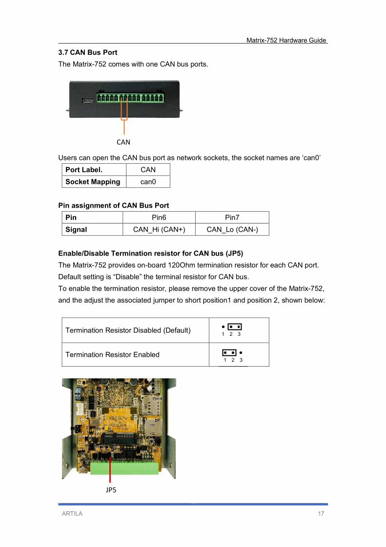
3.7 CAN Bus Port
The Matrix-752 comes with one CAN bus ports.
Users can open the CAN bus port as network sockets, the socket names are ‘can0’
Port Label. CAN
Socket Mapping can0
Pin assignment of CAN Bus Port
Pin Pin6 Pin7
Signal CAN_Hi (CAN+) CAN_Lo (CAN-)
Enable/Disable Termination resistor for CAN bus (JP5)
The Matrix-752 provides on-board 120Ohm termination resistor for each CAN port.
Default setting is “Disable” the terminal resistor for CAN bus.
To enable the termination resistor, please remove the upper cover of the Matrix-752,
and the adjust the associated jumper to short position1 and position 2, shown below:
Termination Resistor Disabled (Default)
Termination Resistor Enabled
1 2 3
1 2 3
JP5
CAN

Matrix-752 Hardware Guide
ARTILA 18
3.8 Digital Input
Two channels Digital Input are equipped with 5000Vrms photocoupler isolation which
share the same common ground.
Pin assignment of Digital Input
Pin Pin8 Pin9 Pin10 Pin11
Signal DI1 COM DI2 COM
The specification of the isolated input channels is:
Logical High: 5~24Vdc
Logical Low: 0~1.5Vdc
Input resistance: [email protected]
Response time: 20µs
Isolation: 5000Vrms
DIx: Isolated digital input channels.
COM: Common ground.
DI 1~2
COM
Digital Input
Matrix-752 Hardware Guide
ARTILA 19
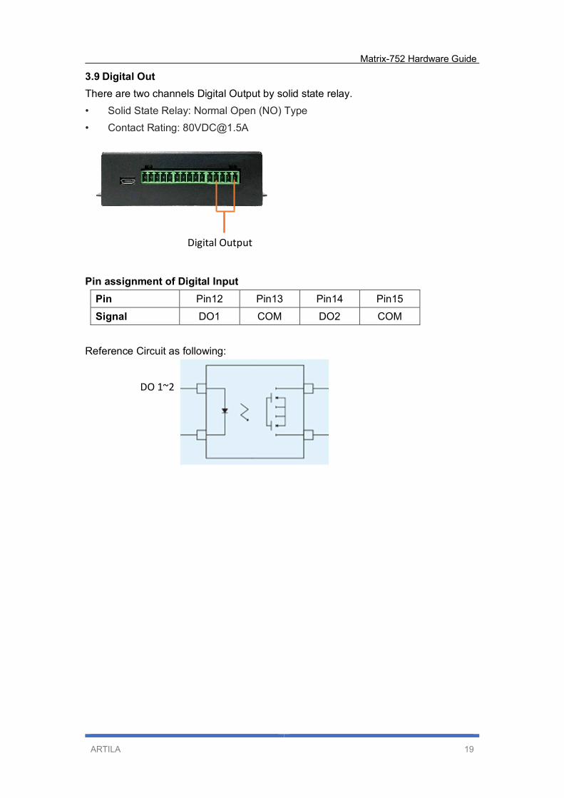
3.9 Digital Out
There are two channels Digital Output by solid state relay.
• Solid State Relay: Normal Open (NO) Type
• Contact Rating: [email protected]
Pin assignment of Digital Input
Pin Pin12 Pin13 Pin14 Pin15
Signal DO1 COM DO2 COM
Reference Circuit as following:
DO 1~2
Digital Output
Matrix-752 Hardware Guide
ARTILA 20
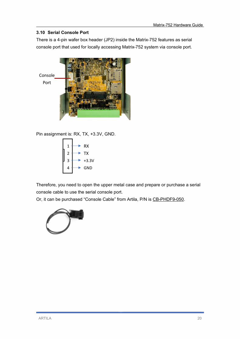
3.10 Serial Console Port
There is a 4-pin wafer box header (JP2) inside the Matrix-752 features as serial
console port that used for locally accessing Matrix-752 system via console port.
Pin assignment is: RX, TX, +3.3V, GND.
Therefore, you need to open the upper metal case and prepare or purchase a serial
console cable to use the serial console port.
Or, it can be purchased “Console Cable” from Artila, P/N is CB-PHDF9-050.
1
2
3
4
RX
TX
+3.3V
GND
Console
Port

Matrix-752 Hardware Guide
ARTILA 21
3.11 External Battery connection
There is a 2Pin wafer (1.2mm pitch) reserved that can be connected to external
battery for RTC
3.12 SD card Socket
There is a micro-SD card socket inside as data storage.
After removed top cover, it can be accessed the SD card.
External Battery
Connection
Micro-SD card socket

Matrix-752 Hardware Guide
ARTILA 22
3.13 miniPCIe Slot
The Matrix-752 comes with a miniPCIe slot and dual holes for antenna reserved for
communication/networking functionality.
3.14 Micro-SIM card socket
There is a micro-SIM card socket inside.
After removed top cover, it can be inserted a micro-SIM card accompanying LTE/4G
module.
Micro-SIM card socket
miniPCIe Slot
Reserved for
Antenna Reserved for
Antenna
Related Documents