Technische Universit¨ at Berlin Faculty IV Computer Science and Electrical Engineering Computer Graphics Group http://www.cg.tu-berlin.de Combining Diffuse Illumination and Frustrated Total Internal Reflection for touch detection by Andreas Holzammer Matrikelnumber: 300708 Berlin, October 22, 2009 Supervisor Uwe Hahne Examiners Prof. Dr. Marc Alexa Prof. Dr.-Ing. Olaf Hellwich

Matlab Opencv Visual PSeye2
Nov 29, 2015
Welcome message from author
This document is posted to help you gain knowledge. Please leave a comment to let me know what you think about it! Share it to your friends and learn new things together.
Transcript
Technische Universitat BerlinFaculty IVComputer Science and Electrical EngineeringComputer Graphics Grouphttp://www.cg.tu-berlin.de
Combining Diffuse Illumination andFrustrated Total Internal Reflection for
touch detection
byAndreas HolzammerMatrikelnumber: 300708
Berlin, October 22, 2009
SupervisorUwe Hahne
ExaminersProf. Dr. Marc Alexa
Prof. Dr.-Ing. Olaf Hellwich


Erklarung
Die selbststandige und eigenhandige Anfertigung versichere ich an Eides Statt.
Berlin, den 22. Oktober 2009.
Andreas Holzammer


Zusammenfassung
Es gibt viele Techniken um mehrere Beruhrungspunkte auf einem Bild-schirm zu erkennen. Die verschiedenen Techniken haben jeweils Vor-und Nachteile. Manche Techniken erfordern viel Druck, andere erkennenBeruhrungen schon wenn der Nutzer noch nicht die Oberflache beruhrtoder die Anzahl der gleichzeitigen Beruhrungen sind eingeschrankt. Vie-le dieser Techniken werden nur dazu eingesetzt Beruhrungspunkte zubestimmen, obwohl manche Hande erkennen konnten. Eine Kombina-tion von diesen Techniken konnte die Vorteile vereinen und somit dieNachteile kompensieren. Diese Diplomarbeit beschaftigt sich mit derKombination von zwei optischen Techniken; Frustrated Total Internal Re-flection und Diffused Illumination. Diese Techniken verwenden infrarotesLicht das an Fingerspitzen/Handen reflektiert und durch eine Kameraaufgezeichnet wird. Es werden verschiedene Techniken vorgestellt unddiskutiert weshalb gerade diese beiden Techniken kombiniert werdensollten. Des Weiteren wird ein Tischaufbau beschrieben, der die zweiTechniken vereint. Fur die Bilddarstellung wird ein Bild von unten aufdie Tischplatte projiziert.
Im laufe der Diplomarbeit wurde eine Software entwickelt, die es demEntwickler ermoglicht schnell und unkompliziert verschiedene Technikenzum erkennen von Beruhrungspunkten zu testen. Diese Software kannBilder von einer angeschlossenen Kamera aufnehmen, vorverarbeiten,analysieren, die analysierten Daten weiterverarbeiten und das Ergebnisan ein Nutzerprogramm schicken. Außerdem konnen noch mehr Informa-tionen, als nur Beruhrungspunkte extrahiert werden – wie die Zuordnungzwischen Beruhrungspunkt und Hand, Hand Orientierung und Abstandzwischen Beruhrungspunkt und der Oberflache. Abschließend wird einNutzerprogamm prasentiert, das diese Zusatzinformationen verarbeitenkann.

Abstract
There are many different approaches for detecting multiple touches on devicesurfaces, which all have their own advantages and disadvantages. Some of the ap-proaches require a lot of pressure to be activated; others are activated even if the useris only close to the surface or are restricted by the number of touches they can detectsimultaneously. Most of the technologies are only used to detect touches, but someof the technologies can be used to detect hands. To use the advantages and overcomethe disadvantages of the individual technologies a combination of technologies shouldbe researched. This thesis presents a combination of two optical technologies, whichare called Frustrated Total Internal Reflection and Diffuse Illumination. Thesetechnologies work with infrared light reflected by fingertips/hands, captured bya camera. Other multi-touch technologies are presented and it is discussed whythese two selected technologies should be combined. A tabletop hardware setup ispresented, which combines both technologies in one setup. For displaying an imageonto the touch surface a projector is used, which projects the image from behind.
In the process of this thesis an easy to use software was developed, for rapidlytesting various processing steps which are needed for the detection process. Withthis software images can be captured, preprocessed, analyzed, resulting informationpost-processed and afterwards send to an application. Additional information canbe derived from these technologies, like the affiliation between fingers and a hand,hand orientation and depth information of touches. Furthermore an application hasbeen created that uses these additional information.
Keywords: Touch detection, Multi-touch, Diffuse Illumination, Frustrated TotalInternal Reflection, Hand detection


Acknowledgments
First, I would like to thank my parents for their consideration andsupport as I prepared this diploma thesis. I would also like to thankBjorn Breitmeyer for all the support that he has given me over the yearsin my studies and especially during my thesis preparation. I am gratefulto Uwe Hahne for supervising me, for great support and for helpfulsuggestions. I also want to thank Jonas Pfeil for his ideas and great “labdays”. I want to thank Bjorn Bollensdorf for assistance regarding thehardware and ideas. I like to thank Matthias Eitz for his great supporthe gave us and the interest he put into our project. I also want to thankmy brother for supporting me so much and getting me out to go bikingfrom time to time. I want to thank Prof. Dr. Marc Alexa for examiningthis work and Prof. Dr.-Ing. Olaf Hellwich for co-examining this work.I want to express my gratitude to all people that proof read this thesis;Rudolf Jacob, Melanie Ott and many others. I also want to thank allthe others whom I missed.


Contents I
Contents
1 Introduction 11.1 Motivation . . . . . . . . . . . . . . . . . . . . . . . . . . . . . . . . 21.2 Goal . . . . . . . . . . . . . . . . . . . . . . . . . . . . . . . . . . . . 31.3 Design of System . . . . . . . . . . . . . . . . . . . . . . . . . . . . . 41.4 Related Work . . . . . . . . . . . . . . . . . . . . . . . . . . . . . . . 4
2 Touch-Sensing Technologies 72.1 Frustrated Total Internal Reflection (FTIR) . . . . . . . . . . . . . . 72.2 Diffused Illumination (DI) . . . . . . . . . . . . . . . . . . . . . . . . 82.3 Diffused Surface Illumination (DSI) . . . . . . . . . . . . . . . . . . . 102.4 Laser Light Plane (LLP) . . . . . . . . . . . . . . . . . . . . . . . . . 112.5 LED Light Plane (LED-LP) . . . . . . . . . . . . . . . . . . . . . . . 122.6 Resistance-Based Touch Surfaces . . . . . . . . . . . . . . . . . . . . 132.7 Capacitance-Based Touch Surfaces . . . . . . . . . . . . . . . . . . . 132.8 Discussion . . . . . . . . . . . . . . . . . . . . . . . . . . . . . . . . . 14
3 Hardware 153.1 Assembly . . . . . . . . . . . . . . . . . . . . . . . . . . . . . . . . . 153.2 Old Setup . . . . . . . . . . . . . . . . . . . . . . . . . . . . . . . . . 153.3 Camera . . . . . . . . . . . . . . . . . . . . . . . . . . . . . . . . . . 163.4 Infrared Bandpass Filter . . . . . . . . . . . . . . . . . . . . . . . . . 173.5 Lens . . . . . . . . . . . . . . . . . . . . . . . . . . . . . . . . . . . . 183.6 Projector . . . . . . . . . . . . . . . . . . . . . . . . . . . . . . . . . 193.7 Infrared Light . . . . . . . . . . . . . . . . . . . . . . . . . . . . . . . 203.8 Surface Layers . . . . . . . . . . . . . . . . . . . . . . . . . . . . . . 22
3.8.1 Compliant Layer . . . . . . . . . . . . . . . . . . . . . . . . . 223.8.2 Projection Screen . . . . . . . . . . . . . . . . . . . . . . . . . 243.8.3 Protective Layer . . . . . . . . . . . . . . . . . . . . . . . . . 243.8.4 Different Surface Layer Setups . . . . . . . . . . . . . . . . . 25
3.9 Switching Circuit . . . . . . . . . . . . . . . . . . . . . . . . . . . . . 253.10 Power Supply . . . . . . . . . . . . . . . . . . . . . . . . . . . . . . . 26
4 Algorithms 274.1 Image Preprocessing . . . . . . . . . . . . . . . . . . . . . . . . . . . 27
4.1.1 Bright Image Removal . . . . . . . . . . . . . . . . . . . . . . 274.1.2 Ambient Light Subtraction . . . . . . . . . . . . . . . . . . . 284.1.3 Background Subtraction . . . . . . . . . . . . . . . . . . . . . 284.1.4 Hotspot Removal . . . . . . . . . . . . . . . . . . . . . . . . . 284.1.5 Image Normalization of DI Images . . . . . . . . . . . . . . . 29
4.2 Feature Detection . . . . . . . . . . . . . . . . . . . . . . . . . . . . . 304.2.1 Touch Detection . . . . . . . . . . . . . . . . . . . . . . . . . 30
Combining DI and FTIR for touch detection Andreas Holzammer

II Contents
4.2.2 Hand Detection . . . . . . . . . . . . . . . . . . . . . . . . . . 314.2.3 Fingertip Detection . . . . . . . . . . . . . . . . . . . . . . . 314.2.4 Hand Orientation . . . . . . . . . . . . . . . . . . . . . . . . . 35
4.3 Post-processing . . . . . . . . . . . . . . . . . . . . . . . . . . . . . . 364.3.1 Undistortion . . . . . . . . . . . . . . . . . . . . . . . . . . . 364.3.2 Tracking . . . . . . . . . . . . . . . . . . . . . . . . . . . . . . 374.3.3 Calibration . . . . . . . . . . . . . . . . . . . . . . . . . . . . 38
5 Combining Frustrated Total Internal Reflection and Diffused Illumination 395.1 Images of Frustrated Total Internal Reflection and Diffuse Illumination 405.2 Processing Pineline . . . . . . . . . . . . . . . . . . . . . . . . . . . . 415.3 Combination . . . . . . . . . . . . . . . . . . . . . . . . . . . . . . . 425.4 Matching . . . . . . . . . . . . . . . . . . . . . . . . . . . . . . . . . 43
6 DIFTIRTracker 456.1 Graphical User Interface . . . . . . . . . . . . . . . . . . . . . . . . . 466.2 Pipeline . . . . . . . . . . . . . . . . . . . . . . . . . . . . . . . . . . 466.3 Network Interface . . . . . . . . . . . . . . . . . . . . . . . . . . . . . 47
7 Results 497.1 Proof of Concept . . . . . . . . . . . . . . . . . . . . . . . . . . . . . 497.2 Informal User Study . . . . . . . . . . . . . . . . . . . . . . . . . . . 517.3 Conclusion . . . . . . . . . . . . . . . . . . . . . . . . . . . . . . . . 547.4 Future Work . . . . . . . . . . . . . . . . . . . . . . . . . . . . . . . 55
8 Appendix 578.1 Several Spectra of Infrared Bandpass Filters . . . . . . . . . . . . . . 578.2 Projector list . . . . . . . . . . . . . . . . . . . . . . . . . . . . . . . 598.3 Software . . . . . . . . . . . . . . . . . . . . . . . . . . . . . . . . . . 60
8.3.1 Community Core Vision (CCV) . . . . . . . . . . . . . . . . . 608.3.2 CG Tracker . . . . . . . . . . . . . . . . . . . . . . . . . . . . 608.3.3 reacTIVision . . . . . . . . . . . . . . . . . . . . . . . . . . . 618.3.4 Touchlib . . . . . . . . . . . . . . . . . . . . . . . . . . . . . . 62
Bibliography VII
October 22, 2009 Combining DI and FTIR for touch detection
List of Figures III
List of Figures
1.1 Popularity of the search terms “multi touch” . . . . . . . . . . . . . 21.2 Multi-touch Table of Computer Graphics institute . . . . . . . . . . 31.3 Parts of the multi-touch table . . . . . . . . . . . . . . . . . . . . . . 4
2.1 General FTIR setup . . . . . . . . . . . . . . . . . . . . . . . . . . . 82.2 Coupling infrared light into an acrylic plate . . . . . . . . . . . . . . 82.3 General DI setup . . . . . . . . . . . . . . . . . . . . . . . . . . . . . 92.4 General DSI setup . . . . . . . . . . . . . . . . . . . . . . . . . . . . 102.5 Basic Laser Light Plane setup . . . . . . . . . . . . . . . . . . . . . . 112.6 Occlusion of fingers . . . . . . . . . . . . . . . . . . . . . . . . . . . . 122.7 Basic LED Light Plane setup . . . . . . . . . . . . . . . . . . . . . . 12
3.1 A basic optical hardware assembly . . . . . . . . . . . . . . . . . . . 153.2 Point Grey Firefly MV . . . . . . . . . . . . . . . . . . . . . . . . . . 163.3 Spectrum of the Point Grey Firefly MV . . . . . . . . . . . . . . . . 163.4 Infrared bandpass filter from Midwest Optical Systems . . . . . . . . 183.5 Calculation of lens distance . . . . . . . . . . . . . . . . . . . . . . . 193.6 Distortion of the lens . . . . . . . . . . . . . . . . . . . . . . . . . . . 193.7 Principle of ultra-short-throw projector . . . . . . . . . . . . . . . . 203.8 Acer S1200 ultra-short-throw projector . . . . . . . . . . . . . . . . . 203.9 Osram SFH 4250 . . . . . . . . . . . . . . . . . . . . . . . . . . . . . 213.10 Etching layout . . . . . . . . . . . . . . . . . . . . . . . . . . . . . . 223.11 Placement of the infrared illuminators . . . . . . . . . . . . . . . . . 223.12 Streaks . . . . . . . . . . . . . . . . . . . . . . . . . . . . . . . . . . 243.13 Surface layers for an FTIR setup . . . . . . . . . . . . . . . . . . . . 253.14 Switching Circuit . . . . . . . . . . . . . . . . . . . . . . . . . . . . . 26
4.1 Hotspot . . . . . . . . . . . . . . . . . . . . . . . . . . . . . . . . . . 294.2 Illumination of the surface . . . . . . . . . . . . . . . . . . . . . . . . 304.3 Convexity Defects of a Hand . . . . . . . . . . . . . . . . . . . . . . 324.4 Smoothed and non-smoothed contour . . . . . . . . . . . . . . . . . 324.5 Dominant point detection . . . . . . . . . . . . . . . . . . . . . . . . 344.6 Orientation angle theta, derived from central moments . . . . . . . . 364.7 Example image of checkerboard . . . . . . . . . . . . . . . . . . . . . 374.8 States of a touch, derived by tracking touches . . . . . . . . . . . . . 37
5.1 Idea of the thesis . . . . . . . . . . . . . . . . . . . . . . . . . . . . . 395.2 Comparison of hand touch with pressure . . . . . . . . . . . . . . . . 405.3 Comparison of hand touch with no pressure . . . . . . . . . . . . . . 405.4 Comparison of flat hand touch . . . . . . . . . . . . . . . . . . . . . 415.5 Comparison of touches close together . . . . . . . . . . . . . . . . . . 415.6 FTIR, DI pipeline . . . . . . . . . . . . . . . . . . . . . . . . . . . . 42
Combining DI and FTIR for touch detection Andreas Holzammer
IV List of Figures
5.7 FTIR and DI LEDs on vs multiplied . . . . . . . . . . . . . . . . . . 425.8 FTIR and DI switched on vs multiplied . . . . . . . . . . . . . . . . 43
6.1 DIFTIRTracker . . . . . . . . . . . . . . . . . . . . . . . . . . . . . . 456.2 Parts of the DIFTIRTracker . . . . . . . . . . . . . . . . . . . . . . . 466.3 Hand TUIO Package . . . . . . . . . . . . . . . . . . . . . . . . . . . 47
7.1 Hand menu . . . . . . . . . . . . . . . . . . . . . . . . . . . . . . . . 497.2 Determination if the hand is a right or a left hand . . . . . . . . . . 507.3 Community Earth . . . . . . . . . . . . . . . . . . . . . . . . . . . . 517.4 Gestures used by Community Earth . . . . . . . . . . . . . . . . . . 527.5 Labyrinth application . . . . . . . . . . . . . . . . . . . . . . . . . . 537.6 Pipelines with non combined technologies . . . . . . . . . . . . . . . 537.7 Pipelines with combined technologies . . . . . . . . . . . . . . . . . . 54
8.1 Spectrum of one overexposed photo negative . . . . . . . . . . . . . 578.2 Spectrum of two overexposed photo negative . . . . . . . . . . . . . 578.3 Spectrum of one floppy disk . . . . . . . . . . . . . . . . . . . . . . . 588.4 Spectrum of two floppy disk . . . . . . . . . . . . . . . . . . . . . . . 588.5 Community Core Vision (CCV) . . . . . . . . . . . . . . . . . . . . . 608.6 CG Tracker . . . . . . . . . . . . . . . . . . . . . . . . . . . . . . . . 618.7 ReacTIVision . . . . . . . . . . . . . . . . . . . . . . . . . . . . . . . 61
October 22, 2009 Combining DI and FTIR for touch detection
List of Tables V
List of Tables
3.1 Specification of the Point Grey Firefly MV . . . . . . . . . . . . . . . 173.2 Specification of the lens . . . . . . . . . . . . . . . . . . . . . . . . . 183.3 Specification of the Acer S1200 . . . . . . . . . . . . . . . . . . . . . 203.4 Parallel port data pins used for switching . . . . . . . . . . . . . . . 26
Combining DI and FTIR for touch detection Andreas Holzammer


Chapter 1
Introduction
There are several ways to interact with the computer. The oldest interaction methodis the keyboard and later the mouse made a profound impact on in computerinteraction. The Zuse Z3 (1941), the first computer even had buttons to interactwith the computer. Later these buttons formed a keyboard.
The mouse was invented in 1963/1964 by a team around Douglas C. Engelbartand William English at the Stanford Research Institute (SRI). This mouse enabledthe user to point in a 2D space, which indirectly manipulates the cursor on thecomputer monitor.
These two methods are still widely used at the present time. Almost everycomputer has a keyboard and a mouse. This adds up to about 60 years of successfor the keyboard and 40 years of success for the mouse. Many other interactionmethods have been invented but no other technology has had as much success.
Touchpads were introduced when notebooks became successful. This pad is placedbeside the keyboard and can normally only track one fingertip. It is also small insize and without display technology. Today there are multi-touch touchpads, butwith some limitations, such as the size of the pad and number of fingers it candetect.
Experience has shown that users would prefere an interaction with the computerin a very simple and natural manner. They normally work with their hands, so anatural interface for the hand is needed. The user desires a visual feedback from thecomputer and wants to interact with the displayed content. Obviously it would benice if the user is able to touch the visual feedback to interact with the computer.
Touchscreens where invented in the late 1960s. But the first commercial touch-screen computer, the HP-150, was presented not before 1983. These touchscreenscould only detect one touch point.
The user has two hands, ten fingers, and wants to use both hands to interact withhis tools. For example, if a human wants to cut a tree branch into two parts, theuser holds the branch with one hand and the saw with the other. He then cuts thebranch into two parts. It is very natural to use two hands to work, although it isnot the case for all tasks. Why should the user be restricted to using just one fingerto interact with a computer? Humans often work with two hands very productively,but on the computer it has not always been so successful.
Users would like to have a user interface which is very intuitive and sensitiveenough to that little pressure is needed to interact with the device. The multi-touchtechnology enables the user to employ both hands and even use the computer withother people at the same time.
1
2 1. Introduction
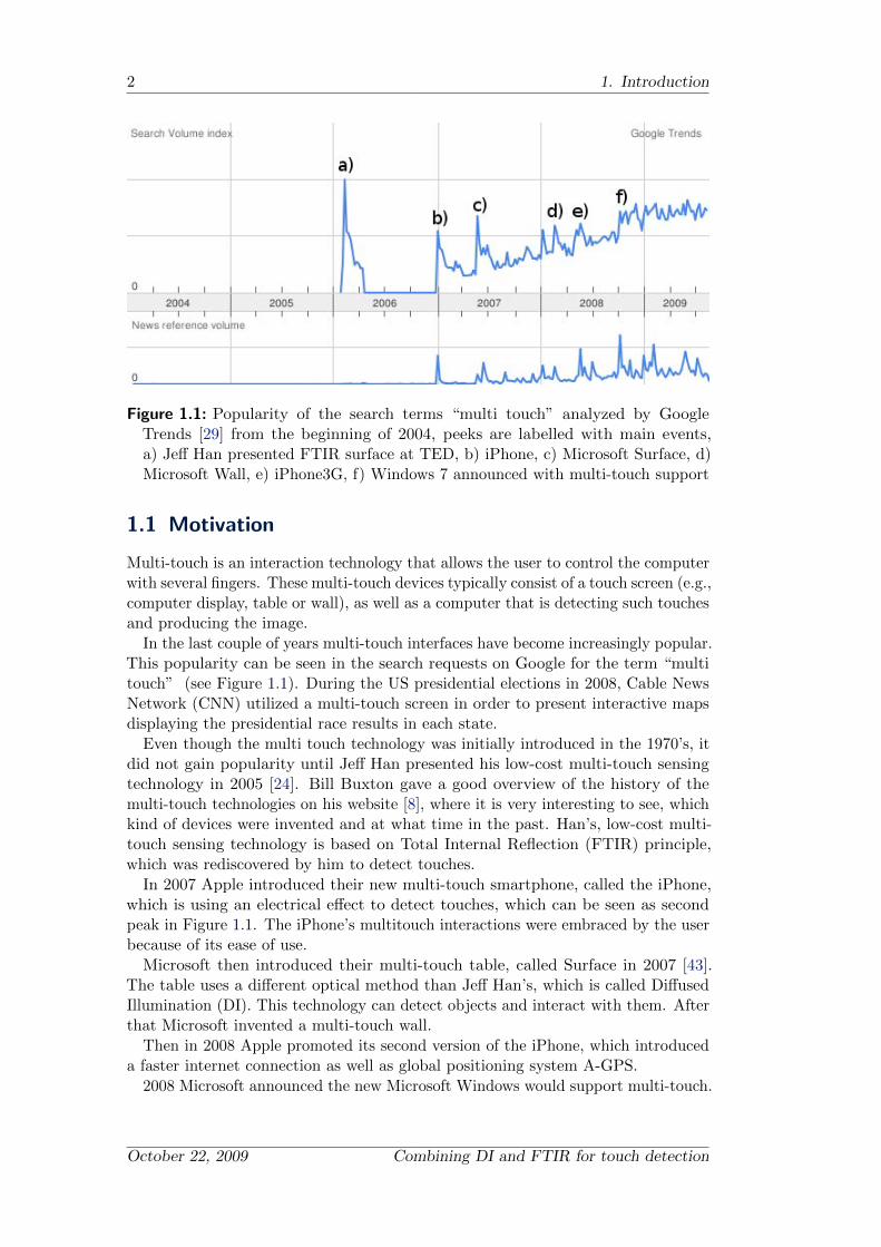
Figure 1.1: Popularity of the search terms “multi touch” analyzed by GoogleTrends [29] from the beginning of 2004, peeks are labelled with main events,a) Jeff Han presented FTIR surface at TED, b) iPhone, c) Microsoft Surface, d)Microsoft Wall, e) iPhone3G, f) Windows 7 announced with multi-touch support
1.1 Motivation
Multi-touch is an interaction technology that allows the user to control the computerwith several fingers. These multi-touch devices typically consist of a touch screen (e.g.,computer display, table or wall), as well as a computer that is detecting such touchesand producing the image.
In the last couple of years multi-touch interfaces have become increasingly popular.This popularity can be seen in the search requests on Google for the term “multitouch” (see Figure 1.1). During the US presidential elections in 2008, Cable NewsNetwork (CNN) utilized a multi-touch screen in order to present interactive mapsdisplaying the presidential race results in each state.
Even though the multi touch technology was initially introduced in the 1970’s, itdid not gain popularity until Jeff Han presented his low-cost multi-touch sensingtechnology in 2005 [24]. Bill Buxton gave a good overview of the history of themulti-touch technologies on his website [8], where it is very interesting to see, whichkind of devices were invented and at what time in the past. Han’s, low-cost multi-touch sensing technology is based on Total Internal Reflection (FTIR) principle,which was rediscovered by him to detect touches.
In 2007 Apple introduced their new multi-touch smartphone, called the iPhone,which is using an electrical effect to detect touches, which can be seen as secondpeak in Figure 1.1. The iPhone’s multitouch interactions were embraced by the userbecause of its ease of use.
Microsoft then introduced their multi-touch table, called Surface in 2007 [43].The table uses a different optical method than Jeff Han’s, which is called DiffusedIllumination (DI). This technology can detect objects and interact with them. Afterthat Microsoft invented a multi-touch wall.
Then in 2008 Apple promoted its second version of the iPhone, which introduceda faster internet connection as well as global positioning system A-GPS.
2008 Microsoft announced the new Microsoft Windows would support multi-touch.
October 22, 2009 Combining DI and FTIR for touch detection

1.2 Goal 3
Figure 1.2: Multi-touch Table of Computer Graphics institute
User studies have shown that a direct manipulation with one or more fingers canincrease performance dramatically in contrast to using a mouse [38]. Hence, if twohands are used instead of just one a higher performance can be achieved as Buxtonet al. are stating [9].
Wigdor et al. [55] state that it is very important for user interaction satisfactionon a multi-touch device that there is accurate touch detection. The user becomesfrustrated or even loses the sense of control if the system is not responding inthe way the user expects it to. This can have several causes like the system notbeing responsive, hardware failing to detect the input, input delivering the wronglocation or input not mapping to the expected function. The existing multi-touchtechnologies have their own advantages and disadvantages.
1.2 Goal
The goal of this diploma thesis is to enhance the touch detection of the multi-touchtable at the Technical University Berlin, which is shown in Figure 1.2. The issueof the old table was the touch sensivity of the panel. Users must push very hard,particularly if the user drags his finger on the surface to interact with the table.Many people are not comfortable with pushing very hard while they are dragging afinger on surface, especially if the surface is very glossy. On the other hand witha different technology called diffused illumination sensitivity is very high, but itis difficult to sense whether a user is really touching the surface or is just abovethe surface. The idea is to combine these two technologies to produce sensitiveand accurate touch detection. This combination needs to be studied, not only howthe touch information is derived, but also how connections between touches andthe hand could be established to enhance the human-computer interaction. Thisinformation could be used to approximate how many people work on the table.
Combining DI and FTIR for touch detection Andreas Holzammer

4 1. Introduction
1.3 Design of System
Client
Touch Server
Figure 1.3: Parts of the multi-touch table
The basic idea of the multi-touch table is to have one device with all the hardwarethat is required to detect various touches, which is shown in Figure 1.3. Thecomputer underneath the table, which we call this the touch server, does all thetouch detection. This touch server is providing all the data that is detected withthe table’s hardware to a client computer which runs an application. This clientcomputer processes the data which is transfered via network.
1.4 Related Work
Many people are working on interaction models with the computer like the Human-Computer Interaction (HCI) community, which include the Association for ComputerMachinery (ACM) Symposium on User Interface Software and Technology (UIST),ACM Conference on Human Factors in Computing Systems (CHI) and HCI Inter-national, even a user community has been created which conducts research in thisfield, the Natural User Interface Group (NUI Group) [22]. A lot of these people areputting a great deal of effort into building their own multi-touch tables and evenresearchers contribute to this community.
But there are also commercial efforts being made in multi-touch technology.Microsoft developed a multi-touch table and introduced it in May 2007. Thistable is 56 cm high, 53 cm deep and 107 cm wide. It has a 30-inch display andhouses a Windows Vista computer inside. The display has a native resolution of1024x768 pixels. This table can detect touches and recognize objects. MicrosoftSurface also uses an optical method to detect touches and objects, which is calledDiffused Illumination. It uses an array of five cameras for imaging. The computerthat is integrated in the table is processing the data of these cameras and projectsan image with a projector built into the table’s surface. Microsoft also supplies aSoftware Development Kit (SDK) for writing own multi-touch applications.
Apple developed the iPhone with a multi-touch interface, using an electronictechnology that uses the capacity between the human body and the panel. Suchsensors can be built fairly thin, but cannot scale as well, in contrast to the opticalmethods and are expensive to produce. Firmware and the design of the controllerrestrict the number of touches it can detect simultaneously. Apple also has a SDKfor their iPhone to write own applications.
But there are not only commercial products, for example, the UnMousePad [50],
October 22, 2009 Combining DI and FTIR for touch detection
1.4 Related Work 5
which is a flexible and inexpensive multi-touch input device. It is just a pad that ispressure sensitive, but the authors say it can also be developed to be transparentas an overlay to displays. It uses a principle called Interpolating Force SensitiveResistance, which is a electric method of sensing multiple touches on a surface. Theauthors print two conductive layers with wires. One layer is positioned horizontal andone vertical. Between those layers is a resistive layer. These wires are connected if auser touches the pad, which is measured by a micro controller. These measurementresults form an image of pressure upon the surface, which is analyzed to extracttouch information.
In 2003 Jorda et al.[34] created a table in which a user can make music withvarious objects, called rectable. These objects are recognized by the table and theuser can interact with a music software to make music. They use the optical methodDiffused Illumination to detect fiduciary marker (fiducial) on the objects. First theyput markers on the fingers to find fingers with the existing software. Later theyincluded normal touch detection as well as touch interaction. Kaltenbrunner et al.,a member of the research group introduced in 2005 a standardized network protocolfor touches and objects.
In 2008 Izadi et al. from Microsoft research presented in 2008 a new surfacetechnology called SecondLight [32], where two projectors are combined to produceone projection image to the table surface and one to an object above the surface.They used a special acrylic plate which can be switched diffused with 60 Hz. Acombination of the Frustrated Total Internal Reflection effect and the DiffusedIllumination is used to detect touches and objects at the same time.
Weiss et al. introduced in 2009 a multi-touch table which can be used withsilicone objects, like buttons, sliders, knobs and keyboards. The labeling of theseobjects is produced by the projector that is used for image displaying. They use acombination of the Frustrated Total Internal Reflection and Diffused Illuminationfor the detection of touches and the silicone objects.
Combining DI and FTIR for touch detection Andreas Holzammer

Chapter 2
Touch-Sensing Technologies
Many multi-touch technologies have been invented. For better understanding whyFrustrated Total Internal Reflection and Diffused Illumination can be combined toenhance touch detection, we need to know how these technologies work and whatother technologies could be used in combination. First the optical technologies aredescribed and later on the electric technologies. This is only an incomplete list,because this would go beyond our scope of this thesis.
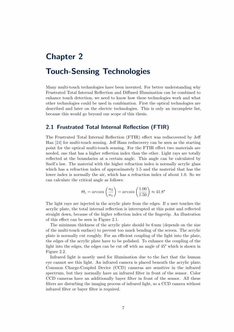
2.1 Frustrated Total Internal Reflection (FTIR)
The Frustrated Total Internal Reflection (FTIR) effect was rediscovered by JeffHan [24] for multi-touch sensing. Jeff Hans rediscovery can be seen as the startingpoint for the optical multi-touch sensing. For the FTIR effect two materials areneeded, one that has a higher reflection index than the other. Light rays are totallyreflected at the boundaries at a certain angle. This angle can be calculated bySnell’s law. The material with the higher refraction index is normally acrylic glasswhich has a refraction index of approximately 1.5 and the material that has thelower index is normally the air, which has a refraction index of about 1.0. So wecan calculate the critical angle as follows:
Θc = arcsin
(n2n1
)= arcsin
(1.00
1.50
)≈ 41.8°
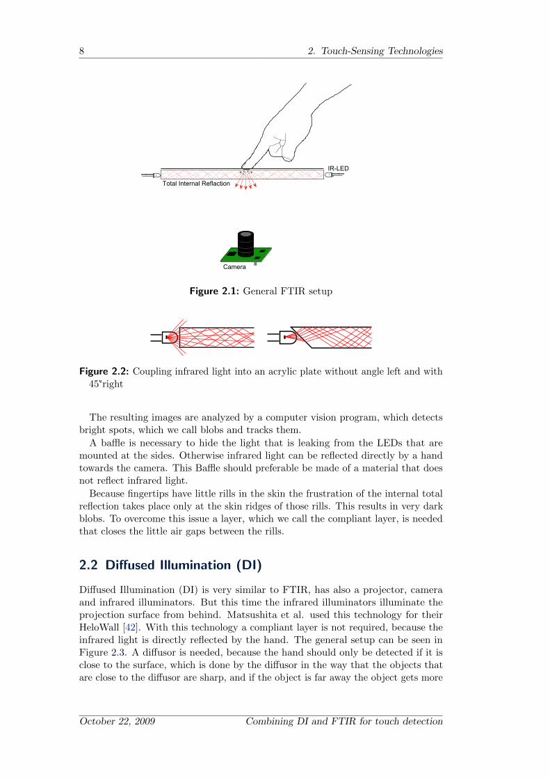
The light rays are injected in the acrylic plate from the edges. If a user touches theacrylic plate, the total internal reflection is interrupted at this point and reflectedstraight down, because of the higher reflection index of the fingertip. An illustrationof this effect can be seen in Figure 2.1.
The minimum thickness of the acrylic plate should be 6 mm (depends on the sizeof the multi-touch surface) to prevent too much bending of the screen. The acrylicplate is normally cut roughly. For an efficient coupling of the light into the plate,the edges of the acrylic plate have to be polished. To enhance the coupling of thelight into the edges, the edges can be cut off with an angle of 45° which is shown inFigure 2.2.
Infrared light is mostly used for illumination due to the fact that the humaneye cannot see this light. An infrared camera is placed beneath the acrylic plate.Common Charge-Coupled Device (CCD) cameras are sensitive in the infraredspectrum, but they normally have an infrared filter in front of the sensor. ColorCCD cameras have an additionally bayer filter in front of the sensor. All thesefilters are disturbing the imaging process of infrared light, so a CCD camera withoutinfrared filter or bayer filter is required.
7
8 2. Touch-Sensing Technologies
Camera
IR-LED
Total Internal Reflaction
Figure 2.1: General FTIR setup
Figure 2.2: Coupling infrared light into an acrylic plate without angle left and with45°right
The resulting images are analyzed by a computer vision program, which detectsbright spots, which we call blobs and tracks them.
A baffle is necessary to hide the light that is leaking from the LEDs that aremounted at the sides. Otherwise infrared light can be reflected directly by a handtowards the camera. This Baffle should preferable be made of a material that doesnot reflect infrared light.
Because fingertips have little rills in the skin the frustration of the internal totalreflection takes place only at the skin ridges of those rills. This results in very darkblobs. To overcome this issue a layer, which we call the compliant layer, is neededthat closes the little air gaps between the rills.
2.2 Diffused Illumination (DI)
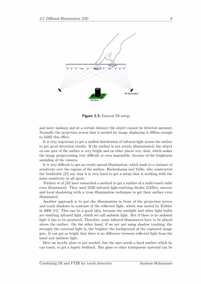
Diffused Illumination (DI) is very similar to FTIR, has also a projector, cameraand infrared illuminators. But this time the infrared illuminators illuminate theprojection surface from behind. Matsushita et al. used this technology for theirHeloWall [42]. With this technology a compliant layer is not required, because theinfrared light is directly reflected by the hand. The general setup can be seen inFigure 2.3. A diffusor is needed, because the hand should only be detected if it isclose to the surface, which is done by the diffusor in the way that the objects thatare close to the diffusor are sharp, and if the object is far away the object gets more
October 22, 2009 Combining DI and FTIR for touch detection
2.2 Diffused Illumination (DI) 9
Camera
IR Illuminator
Figure 2.3: General DI setup
and more unsharp and at a certain distance the object cannot be detected anymore.Normally the projection screen that is needed for image displaying is diffuse enoughto fulfill this effect.
It is very important to get a unified distribution of infrared light across the surfaceto get good detection results. If the surface is not evenly illumninated, the objecton one spot of the surface is very bright and on other places very dark, which makesthe image preprocessing very difficult or even impossible, because of the brightnesssampling of the camera.
It is very difficult to get an evenly spread illumination, which leads to a variance ofsensitivity over the regions of the surface. Hochenbaum and Vallis, who constructedthe bricktable [25] say that it is very hard to get a setup that is working with thesame sensitivity in all spots.
Teichert et al.[33] have researched a method to get a surface of a multi-touch tableeven illuminated. They used 2520 infrared light-emitting diodes (LEDs), mirrorsand local shadowing with a cross illumination technique to get their surface evenilluminated.
Another approach is to put the illumination in front of the projection screenand track shadows in contrast of the reflected light, which was stated by Echtlerin 2008 [15]. This can be a good idea, because the sunlight and other light bulbsare emitting infrared light, which we call ambient light. But if there is no ambientlight it has to be produced. Therefore, some infrared illuminators have to be placedabove the surface. On the other hand, if we are not using shadow tracking; thestronger the external light is, the brighter the background of the captured imagegets. It can get so bright that there is no difference between reflected light from thehand and ambient light.
Here an acrylic plate is not needed, but the user needs a hard surface which hecan touch, to get a haptic feedback. But glass or other transparent material can be
Combining DI and FTIR for touch detection Andreas Holzammer
10 2. Touch-Sensing Technologies
IR-LED
Camera
Figure 2.4: General DSI setup
used for that purpose. The projection screen in this case can be either placed belowthe acrylic plate or above, but this depends on the touch feeling of the projectionscreen or the material that is used for the haptic feedback.
One major advantage of rear diffused illumination is that it can be used to detectobjects or even fiducial markers.
2.3 Diffused Surface Illumination (DSI)
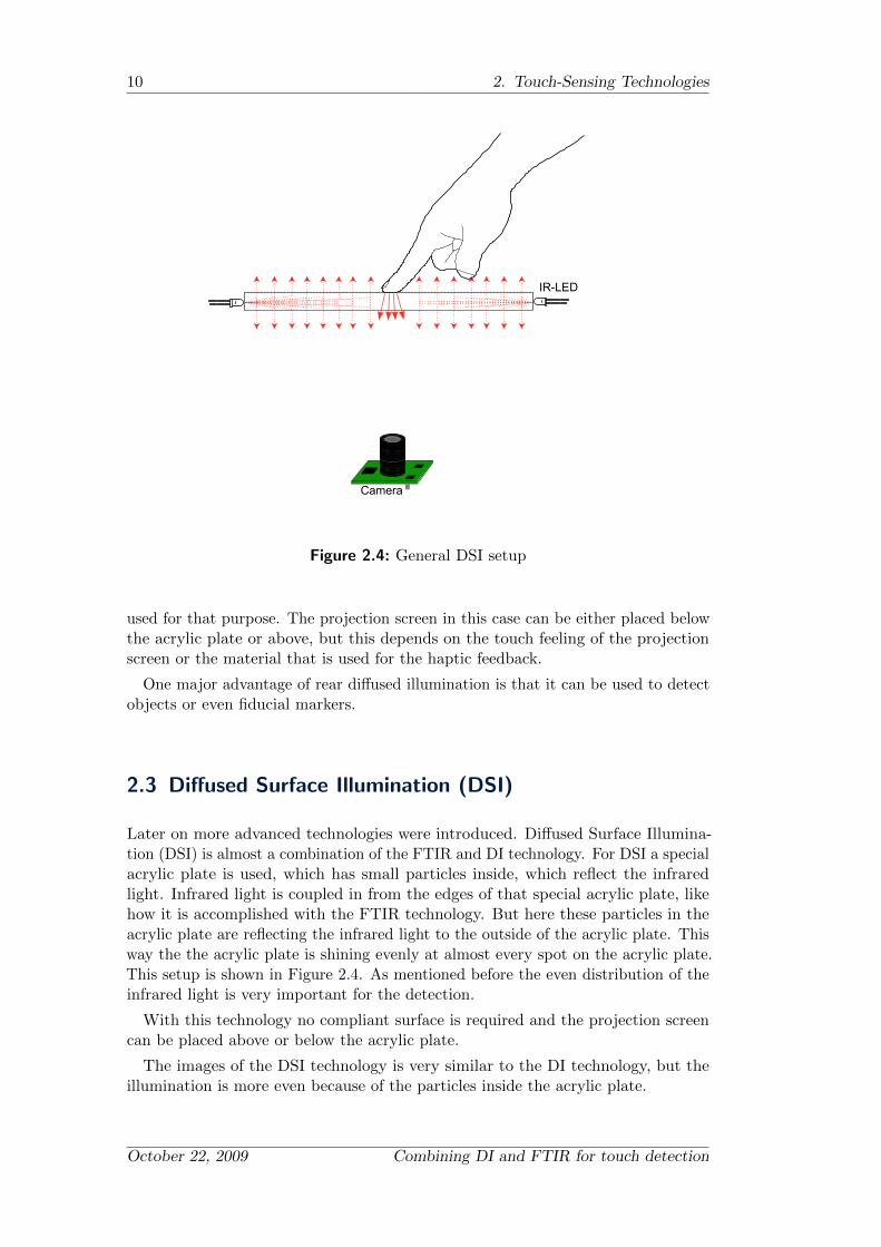
Later on more advanced technologies were introduced. Diffused Surface Illumina-tion (DSI) is almost a combination of the FTIR and DI technology. For DSI a specialacrylic plate is used, which has small particles inside, which reflect the infraredlight. Infrared light is coupled in from the edges of that special acrylic plate, likehow it is accomplished with the FTIR technology. But here these particles in theacrylic plate are reflecting the infrared light to the outside of the acrylic plate. Thisway the the acrylic plate is shining evenly at almost every spot on the acrylic plate.This setup is shown in Figure 2.4. As mentioned before the even distribution of theinfrared light is very important for the detection.
With this technology no compliant surface is required and the projection screencan be placed above or below the acrylic plate.
The images of the DSI technology is very similar to the DI technology, but theillumination is more even because of the particles inside the acrylic plate.
October 22, 2009 Combining DI and FTIR for touch detection
2.4 Laser Light Plane (LLP) 11
Camera
Figure 2.5: Basic Laser Light Plane setup
2.4 Laser Light Plane (LLP)
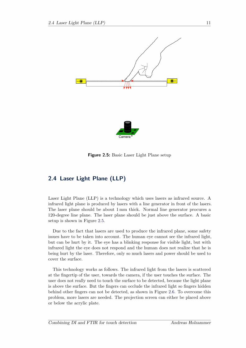
Laser Light Plane (LLP) is a technology which uses lasers as infrared source. Ainfrared light plane is produced by lasers with a line generator in front of the lasers.The laser plane should be about 1 mm thick. Normal line generator procures a120-degree line plane. The laser plane should be just above the surface. A basicsetup is shown in Figure 2.5.
Due to the fact that lasers are used to produce the infrared plane, some safetyissues have to be taken into account. The human eye cannot see the infrared light,but can be hurt by it. The eye has a blinking response for visible light, but withinfrared light the eye does not respond and the human does not realize that he isbeing hurt by the laser. Therefore, only so much lasers and power should be used tocover the surface.
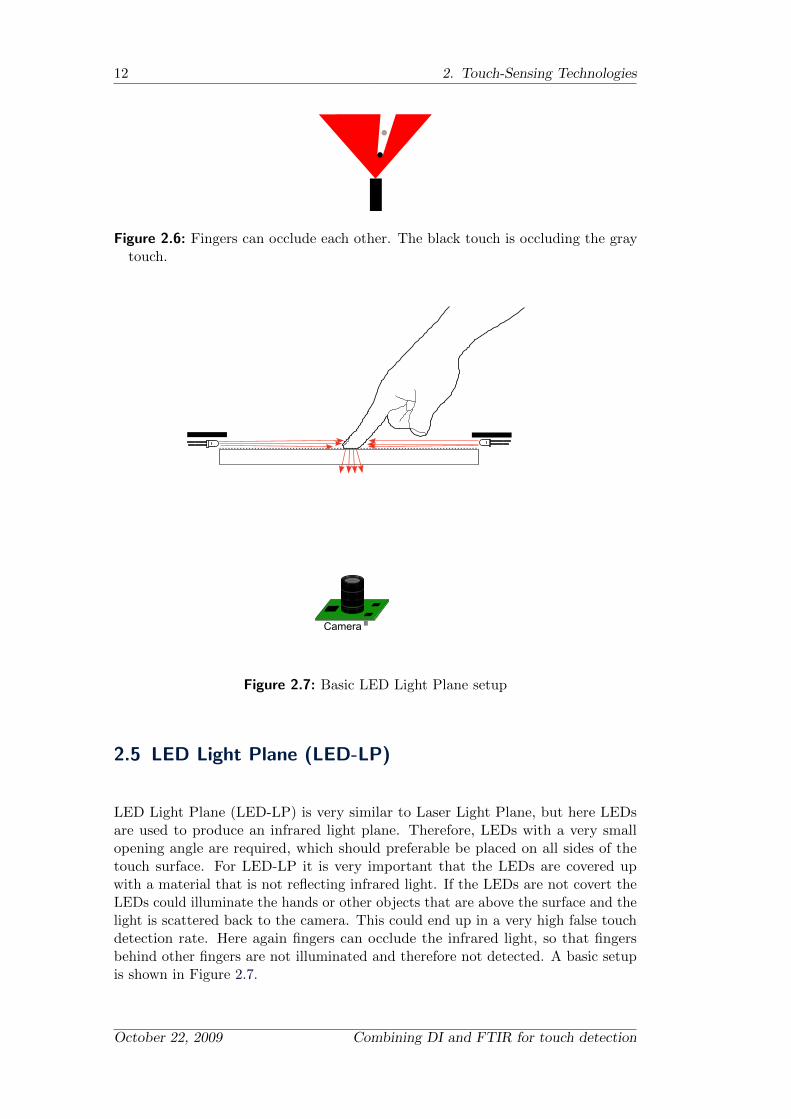
This technology works as follows. The infrared light from the lasers is scatteredat the fingertip of the user, towards the camera, if the user touches the surface. Theuser does not really need to touch the surface to be detected, because the light planeis above the surface. But the fingers can occlude the infrared light so fingers hiddenbehind other fingers can not be detected, as shown in Figure 2.6. To overcome thisproblem, more lasers are needed. The projection screen can either be placed aboveor below the acrylic plate.
Combining DI and FTIR for touch detection Andreas Holzammer
12 2. Touch-Sensing Technologies
Figure 2.6: Fingers can occlude each other. The black touch is occluding the graytouch.
Camera
Figure 2.7: Basic LED Light Plane setup
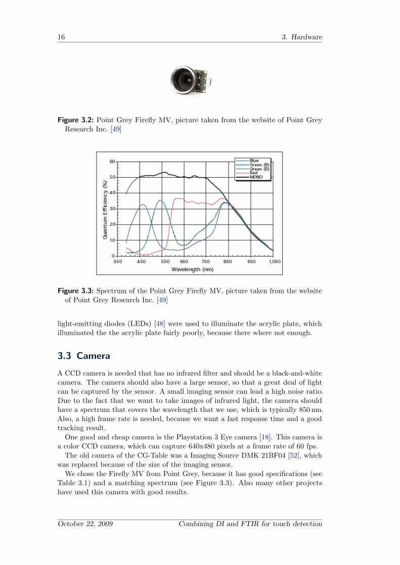
2.5 LED Light Plane (LED-LP)
LED Light Plane (LED-LP) is very similar to Laser Light Plane, but here LEDsare used to produce an infrared light plane. Therefore, LEDs with a very smallopening angle are required, which should preferable be placed on all sides of thetouch surface. For LED-LP it is very important that the LEDs are covered upwith a material that is not reflecting infrared light. If the LEDs are not covert theLEDs could illuminate the hands or other objects that are above the surface and thelight is scattered back to the camera. This could end up in a very high false touchdetection rate. Here again fingers can occlude the infrared light, so that fingersbehind other fingers are not illuminated and therefore not detected. A basic setupis shown in Figure 2.7.
October 22, 2009 Combining DI and FTIR for touch detection

2.6 Resistance-Based Touch Surfaces 13
2.6 Resistance-Based Touch Surfaces
Another group of multi-touch technologies are the electrical technologies. Resistance-based touch surfaces have two conductive layers, one with horizontal lanes andone with vertical lanes. These two layers are separated with an insulation layer,which is normally formed by tiny silicon dots. Above these layers typically a flexiblehard-coated layer is placed, which protects the layers beneath. The bottom normallyconsists of a glass layer to give a base for touching. A controller applies voltageto one of the conductive layers and measures the output of the lanes at the otherlayer. If a user touches the surface the lanes of the horizontal and vertical layersare connected, and current can flow. The controller changes the voltage layer andthe measuring layer to determine the exact position. This method has a very lowpower consumption. The surface can be used with fingers and a stylus, because itjust needs pressure.
A big disadvantage of this method is that the touch layer has only a lighttransmission of about 75%-85% and addtionally screenprotection cannot be appliedwithout interfering with the touch detection. These touch surfaces are used forsmall devices like the Nintendo DS [10]. More information about resistance-based(multi)-touch displays can be found in [14].
2.7 Capacitance-Based Touch Surfaces
Due to the fact that the human body is an electrical conductor, humans can changethe charge of a capacitance system. Capacitive touch surfaces are relatively expensiveto produce and the accuracy is rather bad in contrast to the other technologies.Capacitance-based touch surfaces can be divided into two main classes:
Surface Capacitance
Projected Capacitance
The surfaces of Surface Capacitance touch panels consists of a thin conductivelayer on a glass substrate which is transparent and serves as an electrode of acapacitor. The corners of the conductive layer are connected to a voltage source viaa sensitive current measuring system. If a user touches the surface, the charge istransported from the conductive layer to the human body. The drawn current fromthe corners is measured and a position is estimated.
Projected capacitive touch surfaces consist of a capacitive sensorgrid, which isnormally between two protective glass layers. The sensorgrid can measure thecapacitance forms between the finger and the grid, while the user is touching thesurface. The touch position is derived due to the change of electrical propertiesof the sensorgrid. This method can detect fingertips even if they are not touchingthe surface, because the electrical properties already change if the finger is closeto the surface. This type of panel can be used in rough environments such aspublic installations because it can be covert with a non-conductive material withoutinterfering the touch detection. Due to the sensor grid, multiple touches can bederived more easily, compared to the surface-capacitance based technology.
Combining DI and FTIR for touch detection Andreas Holzammer

14 2. Touch-Sensing Technologies
One example of capacitive touch surfaces is the DiamondTouch system createdby Dietz and Leigh in 2003 [13], which is a multi-user, debris-tolerant, touch-and-gesture-activated screen for supporting small group collaborations. They transmita signal, which depends on the location on the table through antennas, and if theuser touches the screen the signal is capacitively coupled to the chair where it isreceived and analyzed. This leads into the restriction that only four users can bedistinguished.
Another famous device is the iPhone [28] from Apple, which uses a capacitivetouch surface, but not much technical information about it, is known.
2.8 Discussion
After the presentation of the different multi-touch technologies it becomes clearthat not all technologies can be combined. The combination of electric and opticalmethods, would be possible, but if the electrical methods reach a certain size, theelectric issues are getting huge. Because of the desired size of the touch screen120 cm x 90 cm, the electric methods where not chosen. The technologies to combineshould be real multi-touch technologies; the technologies should allow to detect manytouches without restrictions. The infrared light plane technologies are restricted dueto the fact that fingers can be occluded by each other. Some of the electrical methodshave an issue with multiple touches too. Diffused Surface Illumination cannot becombined because it uses a special acrylic plate, which is already a combination ofFrustrated Total Internal Reflection and Diffused Illumination. Both effects alwayshave to be used at the same time; it is not possible to use both effects separatelyand calculating one result.
The advantage of the Frustrated Total Internal Reflection technology is that thereis a strong contrast between a touch and the background. A pressure approximationcan be done with the brightness of a touch, but this can be a disadvantage too,because this technology requires pressure to work and if the user is not applyingpressure to the surface it is not detected. The advantage of Diffused Illumination isthat it is very sensitive to touches, but this again can be a disadvantage too becausethis can lead into a false detection. The combination of Frustrated Total InternalReflection and Diffused Illumination was chosen to combine the advantages of theseboth technologies and balance the disadvantages.
After looking at the technologies, a hardware setup is needed that combines thechosen technologies in one setup.
October 22, 2009 Combining DI and FTIR for touch detection

Chapter 3
Hardware
In this chapter the hardware components which are required to build a multi-touch table with the Frustrated Total Internal Reflection and Diffused Illuminationtechnology are discussed. The hardware which we used for the multi-touch table ispresented afterwards. The multi-touch table of the Institute Computer Graphics (CG-Table) at the Technical University of Berlin [3], was first built as part of a project inwinter of 2007/08. The table had only the FTIR technique to detect touches. Duringthis thesis the table was upgraded with the DI technology; also other hardwareproblems where resolved by part replacing.
3.1 Assembly
A basic hardware assembly of an optical multi-touch display consists of the followingparts: a camera, infrared illuminators, projector and a projection screen, as seen inFigure 3.1.
Camera
ProjectorIR-Illuminator
Projection-screen
Figure 3.1: A basic optical hardware assembly
3.2 Old Setup
The old multi-touch table had a normal projector inside, which needed a fairly longprojection distance, so two mirrors were required to reach the projection distanceneeded for the projection size of 60 inches. The camera was placed just beside theprojector and was taking the images over the mirrors. 98 Osram SFH 485 infrared
15
16 3. Hardware
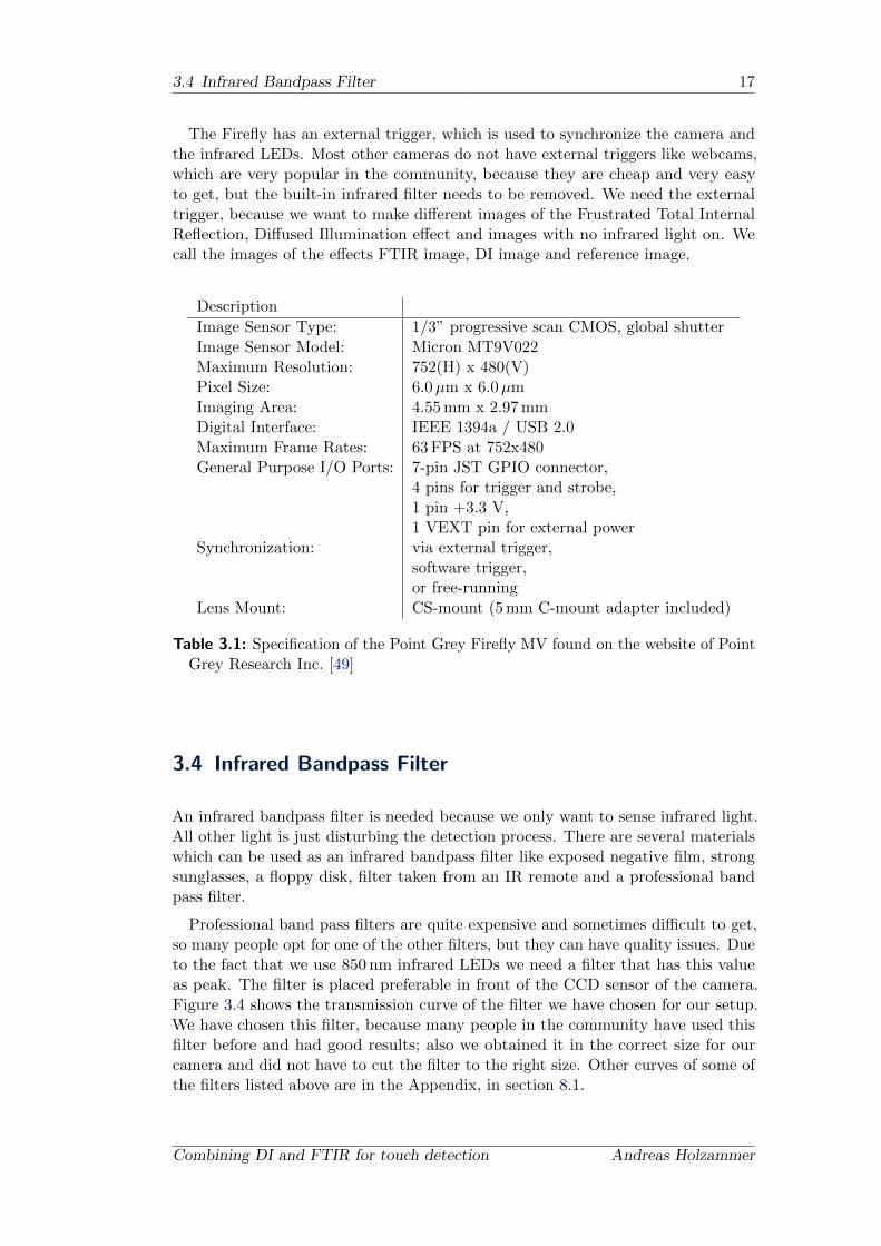
Figure 3.2: Point Grey Firefly MV, picture taken from the website of Point GreyResearch Inc. [49]
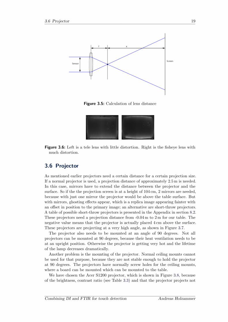
Figure 3.3: Spectrum of the Point Grey Firefly MV, picture taken from the websiteof Point Grey Research Inc. [49]
light-emitting diodes (LEDs) [48] were used to illuminate the acrylic plate, whichilluminated the the acrylic plate fairly poorly, because there where not enough.
3.3 Camera
A CCD camera is needed that has no infrared filter and should be a black-and-whitecamera. The camera should also have a large sensor, so that a great deal of lightcan be captured by the sensor. A small imaging sensor can lead a high noise ratio.Due to the fact that we want to take images of infrared light, the camera shouldhave a spectrum that covers the wavelength that we use, which is typically 850 nm.Also, a high frame rate is needed, because we want a fast response time and a goodtracking result.
One good and cheap camera is the Playstation 3 Eye camera [18]. This camera isa color CCD camera, which can capture 640x480 pixels at a frame rate of 60 fps.
The old camera of the CG-Table was a Imaging Source DMK 21BF04 [52], whichwas replaced because of the size of the imaging sensor.
We chose the Firefly MV from Point Grey, because it has good specifications (seeTable 3.1) and a matching spectrum (see Figure 3.3). Also many other projectshave used this camera with good results.
October 22, 2009 Combining DI and FTIR for touch detection
3.4 Infrared Bandpass Filter 17
The Firefly has an external trigger, which is used to synchronize the camera andthe infrared LEDs. Most other cameras do not have external triggers like webcams,which are very popular in the community, because they are cheap and very easyto get, but the built-in infrared filter needs to be removed. We need the externaltrigger, because we want to make different images of the Frustrated Total InternalReflection, Diffused Illumination effect and images with no infrared light on. Wecall the images of the effects FTIR image, DI image and reference image.
Description
Image Sensor Type: 1/3” progressive scan CMOS, global shutterImage Sensor Model: Micron MT9V022Maximum Resolution: 752(H) x 480(V)Pixel Size: 6.0µm x 6.0µmImaging Area: 4.55 mm x 2.97 mmDigital Interface: IEEE 1394a / USB 2.0Maximum Frame Rates: 63 FPS at 752x480General Purpose I/O Ports: 7-pin JST GPIO connector,
4 pins for trigger and strobe,1 pin +3.3 V,1 VEXT pin for external power
Synchronization: via external trigger,software trigger,or free-running
Lens Mount: CS-mount (5 mm C-mount adapter included)
Table 3.1: Specification of the Point Grey Firefly MV found on the website of PointGrey Research Inc. [49]
3.4 Infrared Bandpass Filter
An infrared bandpass filter is needed because we only want to sense infrared light.All other light is just disturbing the detection process. There are several materialswhich can be used as an infrared bandpass filter like exposed negative film, strongsunglasses, a floppy disk, filter taken from an IR remote and a professional bandpass filter.
Professional band pass filters are quite expensive and sometimes difficult to get,so many people opt for one of the other filters, but they can have quality issues. Dueto the fact that we use 850 nm infrared LEDs we need a filter that has this valueas peak. The filter is placed preferable in front of the CCD sensor of the camera.Figure 3.4 shows the transmission curve of the filter we have chosen for our setup.We have chosen this filter, because many people in the community have used thisfilter before and had good results; also we obtained it in the correct size for ourcamera and did not have to cut the filter to the right size. Other curves of some ofthe filters listed above are in the Appendix, in section 8.1.
Combining DI and FTIR for touch detection Andreas Holzammer

18 3. Hardware
Figure 3.4: Infrared bandpass filter from Midwest Optical Systems, chart takenfrom website of Midwest Optical Systems [53]
Description
Model: Computar T2Z 1816 CSFocal Length: 1.8 - 3.6 mmIris Range: F1.6 - F16CCalculated distance to screen: 55 cm - 115 cm
Table 3.2: Specification of the lens, informations taken from [12]
3.5 Lens
The choosing process of the lens depends on the distance between the camera andthe touch surface. Due to the fact that the surface is very big (60 inches) and nottoo high, a wide lens opening angle is required to capture the full surface. For thispurpose we chose a fisheye lens, which has a barrel distortion effect. This effectis shown in Figure 3.6. Our surface has a dimension of 120 cm x 90 cm at a hightof 103 cm. Figure 3.5 shows the physical setup. With the following equation theneeded distance can be calculated:
x = f ·ScreenSensor
Sensor = 4.55 mm x 2.07 mmScreen = 1200 mm x 900 mm
We chose a vari lens, because we wanted the freedom of placing the cameraat various positions. The specifications of the used lens are shown in Table 3.2.Experiments have shown that the ideal place is in the middle of the acrylic plate.
October 22, 2009 Combining DI and FTIR for touch detection
3.6 Projector 19
Figure 3.5: Calculation of lens distance
Figure 3.6: Left is a tele lens with little distortion. Right is the fisheye lens withmuch distortion.
3.6 Projector
As mentioned earlier projectors need a certain distance for a certain projection size.If a normal projector is used, a projection distance of approximately 2.5 m is needed.In this case, mirrors have to extend the distance between the projector and thesurface. So if the the projection screen is at a height of 104 cm, 2 mirrors are needed,because with just one mirror the projector would be above the table surface. Butwith mirrors, ghosting effects appear, which is a replica image appearing fainter withan offset in position to the primary image; an alternative are short-throw projectors.A table of possible short-throw projectors is presented in the Appendix in section 8.2.These projectors need a projection distance from -0.04 m to 2 m for our table. Thenegative value means that the projector is actually placed 4 cm above the surface.These projectors are projecting at a very high angle, as shown in Figure 3.7.
The projector also needs to be mounted at an angle of 90 degrees. Not allprojectors can be mounted at 90 degrees, because their heat ventilation needs to beat an upright position. Otherwise the projector is getting very hot and the lifetimeof the lamp decreases dramatically.
Another problem is the mounting of the projector. Normal ceiling mounts cannotbe used for that purpose, because they are not stable enough to hold the projectorat 90 degrees. The projectors have normally screw holes for the ceiling mounts,where a board can be mounted which can be mounted to the table.
We have chosen the Acer S1200 projector, which is shown in Figure 3.8, becauseof the brightness, contrast ratio (see Table 3.3) and that the projector projects not
Combining DI and FTIR for touch detection Andreas Holzammer

20 3. Hardware
Figure 3.7: Principle of ultra-short-throw projector
from the side. Also, with this projector no mirrors are needed to project 60 inches.
Figure 3.8: Acer S1200 ultra-short-throw projector, picture taken from web page ofAcer [1]
Description
Projection System DLPNative Resolution 1024 x 768Brightness 2500 LumenContrast 2000:1Projection lens F = 2.6, f = 6.97mmThrow Ratio 0.60:1Projection Screen Size 4.15 m@2 m or 2.082 @1 mProjection Distance 0.5 m – 3.7 mLamp lifetime 4000h(ECO)/3000h(Bright Mode)Distance for 60” 0.72 m
Table 3.3: Specification of the Acer S1200, information taken from [1]
3.7 Infrared Light
As stated before the FTIR and the DI effect is using infrared light, which doesnot interfere with the image projection. For this purpose infrared illuminators are
October 22, 2009 Combining DI and FTIR for touch detection

3.7 Infrared Light 21
needed to illuminate the acrylic plate.Infrared illuminators can be self build out of single light-emitting diodes (LEDs),
LED emitter or LED ribbon:
Single LEDs Can be either normal infrared LEDs or Surface-Mounted Device (SMD)infrared LEDs. The normal infrared LEDs are bigger and easier to solder, butnormally they are less powerful than the SMD LEDs. The SMD LEDs need tobe soldered to a board, which is not needed for the normal LEDs. With singleLEDs the user has the freedom of arranging the LEDs for his own needs. Heis not bound to industrial standards, but needs soldering experience and thetools to do so.
LED emitter Prefabricated emitters, which are used for a DI setup, because theyare normally round and have a large surface. These emitters are normallyused as the headlight for a night-vision camera. These emitters have a densearea of infrared LEDs, so a hotspot is produced. This can be eliminated bybouncing the infrared light off the sides and floor of an enclosed box. Withemitters the user does not need to solder anything.
LED ribbons These are prefabricated LED strips with SMD LEDs on them. Theyare normally used for an FTIR setup. This is the easiest way to build anFTIR setup, because the LED ribbons have an adhesive side and thereforecan be glued to a frame.
For the FTIR method a long thin illuminator is required and for DI an evenillumination is needed. Due to the fact that we want bright spots at the placeswhere the user touches the surface, a great deal of infrared light is needed. We choseSMD LEDs, because they have a higher total radient flux. Most of the people whobuild such multi-touch tables use the SFH 485 from Osram [48]. We used the SFH4250, which is shown in Figure 3.9. We have chosen this LED, because many peoplehave used this LED before and it was recommended by Schoning et al. [51].
Figure 3.9: The Osram SFH 4250 soldered on a board
For the FTIR effect we need to mount the LEDs at the edges of the acrylic plateso the infrared illuminator needs to be long and narrow. For building such a longand thin illuminator a board has been created which fits 24 of these LEDs in groupsof 6. A group consists of the LEDs with a resistor in series. 14 of those boards areused to illuminate the acrylic plate. This custom board was self-etched with thepattern shown in Figure 3.10. The area of each pad which is needed for connectingthe LEDs with the board should be at least 16mm2 for absorbing the heat. Due tothe fact that we are switching on the LEDs only when it is necessary, the LEDs arenot getting too hot and do not need a bigger heat pad.
Combining DI and FTIR for touch detection Andreas Holzammer

22 3. Hardware
Figure 3.10: Etching layout
Figure 3.11: Placement of the infrared illuminators
For the DI effect bigger illuminators are needed. The LEDs are mounted on anormal board which is 16 x 10 cm big. On such a board are 24 LEDs placed infour rows, with six LEDs in each row. The placing of these infrared illuminators isnot easy, because the acrylic plate is reflecting infrared light and these reflectionsinterfere with the touch detection. A position needs to be found that almost nodirect reflection gets to the camera. Positioning of the infrared illuminators on thefloor results into such reflections. Either the illuminators need to be placed at anangle which moves the illuminators outside of the table or they have to be reflectedat a wall. Another approach is to place the illuminators just below the acrylic platenearly vertically, as shown in Figure 3.11
3.8 Surface Layers
The Surface normally consists of different layers. For different touch-detectiontechnologies it can differ what layers are needed and which are not needed. In theChapter 2 we already stated which layers are needed for the different setups. In thissection we discuss what these layers are and which different materials can be usedfor those layers.
3.8.1 Compliant Layer
As stated before, for an FTIR setup we need a compliant layer, which is not neededfor a DI, DSI, LLP and LED-LP setup. A material with a different refraction indexthan the air is needed to frustrate the internal reflection. Since the fingers have rills,there is a lot of air between the finger and the acrylic plate if the user touches thesurface; to fill these air gaps between the finger rills a compliant layer is required.
It is possible to build a multi-touch display without a compliant layer, but theuser needs very greasy fingertips or a lot of pressure to use the display. Baby oilcan be used to substitute the compliant layer, but it needs to be spread out fromtime to time on the acrylic plate. Many people are not comfortable working withbaby oil on their hands and perhaps oil will get on any papers they may have thatare close to the display.
A material is required which is flexible enough for filling the rills of the fingertipsor a material that has a similar refraction index to the acrylic plate. It should beeither transparent or a good rear projection screen. The compliant layer can stick
October 22, 2009 Combining DI and FTIR for touch detection
3.8 Surface Layers 23
to the acrylic plate, but it then needs a refractive index close to the acrylic. Ifan additional projection foil is needed the compliant layer should not stick to theprojection foil.
Silicone
Silicone can be used as the compliant layer due to the fact that its refractive indexis very close to that of the acrylic plate. It can be spread over the acrylic plate.There are several ways to make a smooth layer of silicone on the acrylic plate.
spraying the silicone onto the acrylic plate
roll the silicone onto the acrylic plate
spread out a thin layer with a rigid bar
get a silicone foil
For all the variants described above a low viscosity silicone is needed. Silicone canbe thinned with Zylol or Xylol. This makes the silicone more liquid, but because ofthe mixing process it has little bubbles of air inside. These bubbles could interferewith the FTIR effect, but tests showed that the bubbles are not interfering, actuallythere is no difference between the thinned and normal silicone.
For spraying and rolling the silicone onto the acrylic plate a few layers are needed,because one layer would be too thin to work. The rolling method produces a texturedlayer, so if it is rolled on the acrylic plate the surface of the plate has a texture,which interferes the FTIR effect, because the angles of the rays that travel in theacrylic plate are not perfect anymore. And if the angles are not perfect there is nototal internal reflection.
The issue with silicone is that it easily sticks to other materials. If the projectionfoil sticks to the silicone the total internal reflection is frustrated at this point. Inour tests the projection foil was sticking only short to the silicon, but this effectedstreaks. These streaks can be removed with talcum powder, but the talcum powderalso interferes with the FTIR effect. The problem with bought silicone foil is that itis mostly powdered with talcum, because they sticks very well to each other. It isvery difficult to wash off the talcum powder from the silicone.
Latex
As compliant layer latex can be used too, because it is flexible enough to fulfillthe fingertip rills. Latex is a natural product, so there is no latex that is totallytransparent. The latex has a yellow/brown color. But latex can also be used as theprojection screen. The projection performances are not as good as a professionalback projection screen, but good enough for normal working conditions. Latex isdedicated to human grease, it needs to be cleaned with silicone oil. Latex also sticksto the human skin, so an additional protective layer is required. This layer shouldbe transparent, so that it is not interfering with the image and it should have a nice“touch” feeling, because it is the actual touching layer.
Combining DI and FTIR for touch detection Andreas Holzammer

24 3. Hardware
Figure 3.12: Streaks of thinned silicone at the top and unthinned silicone at thebottom
Discussion
It is very difficult to get an even thick layer of silicone on an acrylic plate. We havetried to roll the silicone on the acrylic, which produced a structure on the siliconewhich interfered with the FTIR effect. We also tried to spread out a thin layer witha rigid bar, which had good results in terms of evenness, but the projection foil stuckto the silicone and produced streaks (shown in Figure 3.12), which is disturbing thetouch detection process. We have chosen a latex layer, because it has no problemswith streaks.
3.8.2 Projection Screen
As projection screen several materials can be used. Sometimes other surface layerscan be used as projection screen.
One cheap approach was stated by Tinkerman from the NUI Group forum [22].He rolled silicone to a vellum paper. This method combines the compliant layer andthe projection screen. This method produces a textured layer of silicon; this is goodbecause then the silicon is not sticking to the acrylic plate. With this layer good,bright blobs are produced by pushing the surface, but the vellum paper is on top soit can be damaged by the touching fingers.
If there are only transparent layers a projection screen is needed. A popular projec-tion screen used by multi-touch display builders is the Grey by Rosco [30], but thereare many other back projection screens that are sufficient. Peau Productions [46]gives a good overview of projection materials.
3.8.3 Protective Layer
For some setups a protective layer is needed, because the layers beneath are sensitiveto scratches or the layer does not have good friction characteristics for touches. Forsetups that do not need to push something in, a thin acrylic layer can be used.With glossy materials the touch feeling is not very smooth because of the frictionon the glossy material. It shows that rough materials have a nice touch feeling; thisis because the friction on this material is less. For example, a sandblasted acrylicplate can be used if it does not disturb the image viewing. For setups where thepush effect is needed, soft Polyvinyl chloride (PVC) can be used. The soft PVCshould be very thin, because it needs to be dented and the thicker the soft PVC is,the harder it is to dent.
October 22, 2009 Combining DI and FTIR for touch detection
3.9 Switching Circuit 25
3.8.4 Different Surface Layer Setups
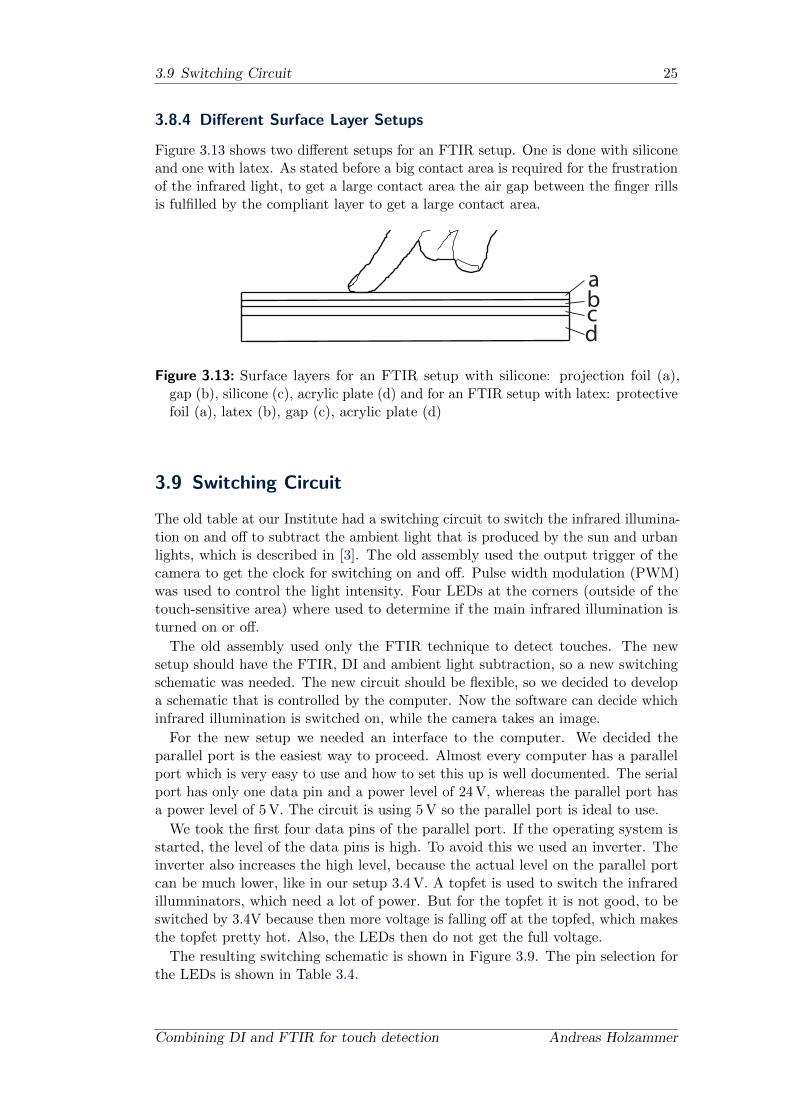
Figure 3.13 shows two different setups for an FTIR setup. One is done with siliconeand one with latex. As stated before a big contact area is required for the frustrationof the infrared light, to get a large contact area the air gap between the finger rillsis fulfilled by the compliant layer to get a large contact area.
abcd
Figure 3.13: Surface layers for an FTIR setup with silicone: projection foil (a),gap (b), silicone (c), acrylic plate (d) and for an FTIR setup with latex: protectivefoil (a), latex (b), gap (c), acrylic plate (d)
3.9 Switching Circuit
The old table at our Institute had a switching circuit to switch the infrared illumina-tion on and off to subtract the ambient light that is produced by the sun and urbanlights, which is described in [3]. The old assembly used the output trigger of thecamera to get the clock for switching on and off. Pulse width modulation (PWM)was used to control the light intensity. Four LEDs at the corners (outside of thetouch-sensitive area) where used to determine if the main infrared illumination isturned on or off.
The old assembly used only the FTIR technique to detect touches. The newsetup should have the FTIR, DI and ambient light subtraction, so a new switchingschematic was needed. The new circuit should be flexible, so we decided to developa schematic that is controlled by the computer. Now the software can decide whichinfrared illumination is switched on, while the camera takes an image.
For the new setup we needed an interface to the computer. We decided theparallel port is the easiest way to proceed. Almost every computer has a parallelport which is very easy to use and how to set this up is well documented. The serialport has only one data pin and a power level of 24 V, whereas the parallel port hasa power level of 5 V. The circuit is using 5 V so the parallel port is ideal to use.
We took the first four data pins of the parallel port. If the operating system isstarted, the level of the data pins is high. To avoid this we used an inverter. Theinverter also increases the high level, because the actual level on the parallel portcan be much lower, like in our setup 3.4 V. A topfet is used to switch the infraredillumninators, which need a lot of power. But for the topfet it is not good, to beswitched by 3.4V because then more voltage is falling off at the topfed, which makesthe topfet pretty hot. Also, the LEDs then do not get the full voltage.
The resulting switching schematic is shown in Figure 3.9. The pin selection forthe LEDs is shown in Table 3.4.
Combining DI and FTIR for touch detection Andreas Holzammer

26 3. Hardware
Figure 3.14: Switching Circuit. There are many more LEDs involved in that circuit,but are not shown.
Pin Purpose
D0 FTIR LEDs
D1 Reference LEDs
D2 External camera trigger
D3 DI LEDs
Table 3.4: Parallel port data pins used for switching
3.10 Power Supply
A power supply is needed for the switching schematic and the infrared illuminators.5 V are needed for the logical circuits and the topfet. To power the infrared LEDs aforward voltage of 12 V is used. There are 6 LEDs in series with a resistor. EachLED has a forward voltage of 1.5 V at a forward current of about 100 mA. Thisresults in a forward voltage of 9V, so the resistor needs to take the rest of the voltage.With Ohms law we calculate the value of the resistor to be 30Ω . We took a 22Ωresistor, because we are switching on the LEDs only for a very short time (about2 ms). This is done to get more illumination power from the LEDs. The pulsing ofthe power is described by the manufacturer of the LEDs.
We took a normal computer power supply for powering the switching schematicand the infrared illuminators.
October 22, 2009 Combining DI and FTIR for touch detection

Chapter 4
Algorithms
After looking at the hardware setup, this section describes algorithms, which areneeded for image preprocessing, touch detection and tracking of FTIR and DI images.The preprocessing of the images extracts the informations we need for the analyzingprocess by filtering the captured images. Afterwards a feature detection is carriedout to find touches and other information in the image. Later this information ispost-processed to transform the touches to the right place on the screen and to tracktouches.
4.1 Image Preprocessing
All images need to be preprocessed to subtract physical and hardware related sideeffects which disturb the analyzing process.
4.1.1 Bright Image Removal
The firefly MV captures sometimes an overexposed image at the beginning of thecapturing process, which have to be removed for the background subtraction andhotspot removal. One basic approach would be to calculate the histogram of eachimage and decide if the image is too bright with a static value. But due to the factthat the algorithm should work for various imaging technologies (FTIR, DI, etc.)the brightness of the image cannot be stated as a constant value. To overcome thisflaw the following adaptive algorithm has been created.
A set of images has to be evaluated, because only then can the typical brightnessbe evaluated. At least 3 images are required if it can be assumed that only oneimage is overexposed. To find the overexposed image the histograms of the imagesare pairwise compared (histogram distance). The algorithm is divided into thefollowing parts:
find the image that has the smallest “histogram distance” to all other images
collect all images that are within a certain distance to the previous foundimage
To find the smallest distance between one image to the others, the accumulateddistances of all images are calculated with a given distance metric. An accumulateddistance is the sum of the distances of one image to all the others. In this list ofdistances the smallest value is searched. This corresponding image has the smallesthistogram distance to all the others.
After this calculation, the distances between the found image and the others arecalculated. Is the distance below a certain value these images are not overexposed.
27
28 4. Algorithms
This algorithm is necessary because it is important that in the background sub-traction algorithm no overexposed image is involved, otherwise the touch detectionis not sensible enough.
4.1.2 Ambient Light Subtraction
As stated before changing light conditions are disturbing the detection as follows. Ifthe background image is statically taken at the beginning and the light conditionschange afterwards the background is changing too. If the background changes thebackground subtraction fails; this can lead into false touch detection, especiallyif the background gets brighter. One solution to this issue is to use an adaptivebackground subtraction, which requires greater performance and also decreases thetouch sensitivity.
Another approach is stated by Alexa et al. [3], to take two images, one with theinfrared light turned on (blob image) and one with the infrared illuminators turnedoff (reference image). The image with the infrared illuminators turned off gives usthe ambient light which is shining into the table. These two images are subtractedto remove the ambient light from the blob image. This method is also described foreye detection by Zhu et al. in 2002 [59] to increase the contrast of the eyes to detectthem. If these images are taken close together, this methods gives good results. Butthis means that a second image have to be taken; each time a blob image has to betaken; this results in half of the frame rate of the camera for the whole setup.
4.1.3 Background Subtraction
The background of the image disturbs the detection algorithms, so it needs to besubtracted, especially for the DI technology, because infrared light is partly directlyreflected by the acrylic plate. Due to the fact that the background is static, becausethe multi-touch table is not moving, in contrast to the touches that are appearing,disappearing and moving, an image can be taken at the beginning and be subtractedfrom each following image. This technique is well known and is described in variouscomputer vision books like “Computer Vision: A Modern Approach” from Forsyth etal. [19]. For this process a few background images are taken, because an overexposedimage would be fatal. To reduce the noise of the images, the maximum brightnessvalue of each pixel is used as background image.
4.1.4 Hotspot Removal
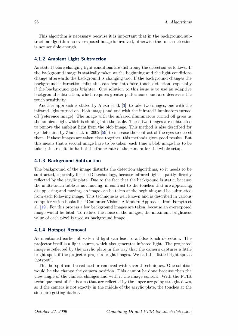
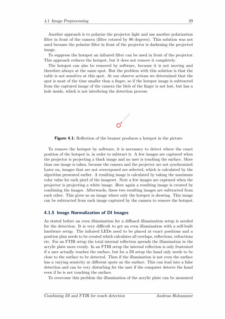
As mentioned earlier all external light can lead to a false touch detection. Theprojector itself is a light source, which also generates infrared light. The projectedimage is reflected by the acrylic plate in the way that the camera captures a littlebright spot, if the projector projects bright images. We call this little bright spot a“hotspot”.
This hotspot can be reduced or removed with several techniques. One solutionwould be the change the camera position. This cannot be done because then theview angle of the camera changes and with it the image content. With the FTIRtechnique most of the beams that are reflected by the finger are going straight down,so if the camera is not exactly in the middle of the acrylic plate, the touches at thesides are getting darker.
October 22, 2009 Combining DI and FTIR for touch detection
4.1 Image Preprocessing 29
Another approach is to polarize the projector light and use another polarizationfilter in front of the camera (filter rotated by 90 degrees). This solution was notused because the polarize filter in front of the projector is darkening the projectedimage.
To suppress the hotspot an infrared filter can be used in front of the projector.This approach reduces the hotspot, but it does not remove it completely.
The hotspot can also be removed by software, because it is not moving andtherefore always at the same spot. But the problem with this solution is that thetable is not sensitive at this spot. At our observe actions we determined that thespot is most of the time smaller than a finger, so if the hotspot image is subtractedfrom the captured image of the camera the blob of the finger is not lost, but has ahole inside, which is not interfering the detection process.
Figure 4.1: Reflection of the beamer produces a hotspot in the picture
To remove the hotspot by software, it is necessary to detect where the exactposition of the hotspot is, in order to subtract it. A few images are captured whenthe projector is projecting a black image and no user is touching the surface. Morethan one image is taken, because the camera and the projector are not synchronized.Later on, images that are not overexposed are selected, which is calculated by thealgorithm presented earlier. A resulting image is calculated by taking the maximumcolor value for each pixel of the imageset. Next a few images are captured when theprojector is projecting a white image. Here again a resulting image is created bycombining the images. Afterwards, these two resulting images are subtracted fromeach other. This gives us an image where only the hotspot is showing. This imagecan be subtracted from each image captured by the camera to remove the hotspot.
4.1.5 Image Normalization of DI Images
As stated before an even illumination for a diffused illumination setup is neededfor the detection. It is very difficult to get an even illumination with a self-builthardware setup. The infrared LEDs need to be placed at exact positions and aposition plan needs to be created which calculates all overlaps, reflections, refractionsetc. For an FTIR setup the total internal reflection spreads the illumination in theacrylic plate more evenly. In an FTIR setup the internal reflection is only frustratedif a user actually touches the surface, but for a DI setup the hand only needs to beclose to the surface to be detected. Then if the illumination is not even the surfacehas a varying sensivity at different spots on the surface. This can lead into a falsedetection and can be very disturbing for the user if the computer detects the handeven if he is not touching the surface.
To overcome this problem the illumination of the acrylic plate can be measured
Combining DI and FTIR for touch detection Andreas Holzammer
30 4. Algorithms
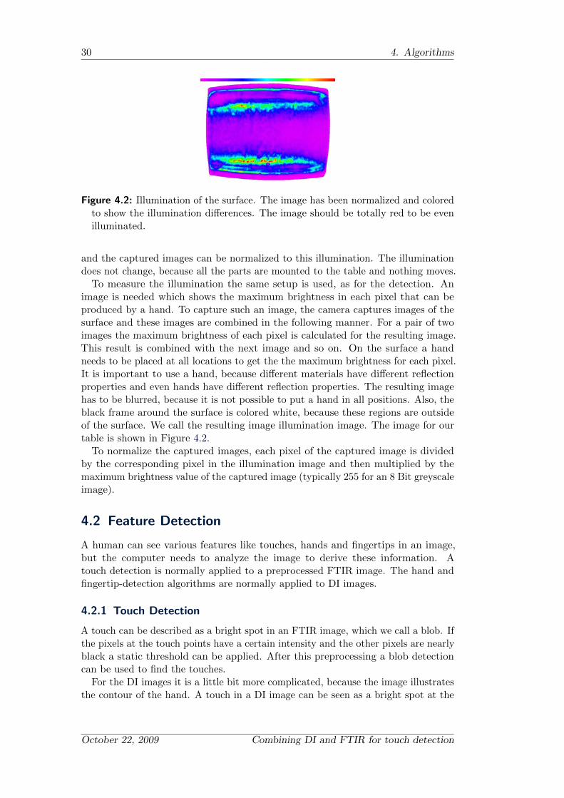
Figure 4.2: Illumination of the surface. The image has been normalized and coloredto show the illumination differences. The image should be totally red to be evenilluminated.
and the captured images can be normalized to this illumination. The illuminationdoes not change, because all the parts are mounted to the table and nothing moves.
To measure the illumination the same setup is used, as for the detection. Animage is needed which shows the maximum brightness in each pixel that can beproduced by a hand. To capture such an image, the camera captures images of thesurface and these images are combined in the following manner. For a pair of twoimages the maximum brightness of each pixel is calculated for the resulting image.This result is combined with the next image and so on. On the surface a handneeds to be placed at all locations to get the the maximum brightness for each pixel.It is important to use a hand, because different materials have different reflectionproperties and even hands have different reflection properties. The resulting imagehas to be blurred, because it is not possible to put a hand in all positions. Also, theblack frame around the surface is colored white, because these regions are outsideof the surface. We call the resulting image illumination image. The image for ourtable is shown in Figure 4.2.
To normalize the captured images, each pixel of the captured image is dividedby the corresponding pixel in the illumination image and then multiplied by themaximum brightness value of the captured image (typically 255 for an 8 Bit greyscaleimage).
4.2 Feature Detection
A human can see various features like touches, hands and fingertips in an image,but the computer needs to analyze the image to derive these information. Atouch detection is normally applied to a preprocessed FTIR image. The hand andfingertip-detection algorithms are normally applied to DI images.
4.2.1 Touch Detection
A touch can be described as a bright spot in an FTIR image, which we call a blob. Ifthe pixels at the touch points have a certain intensity and the other pixels are nearlyblack a static threshold can be applied. After this preprocessing a blob detectioncan be used to find the touches.
For the DI images it is a little bit more complicated, because the image illustratesthe contour of the hand. A touch in a DI image can be seen as a bright spot at the
October 22, 2009 Combining DI and FTIR for touch detection
4.2 Feature Detection 31
fingertips. A fingertip has a certain size, so all bigger spots and smaller spots can beremoved with a bandpass filter. This filter extracts the spots that have the certainsize. Afterwards a threshold is applied and the blobs are detected.
4.2.2 Hand Detection
A human hand is a fairly complex object with five fingers and a palm. Each fingerhas three joints, except for the thumb, which has just two joints. Kang et al. statethat the hand has roughly 27 degrees of freedom [36]. With the 27 degrees of freedomthe hand can make too many poses to detect all of them. Due to the fact that justone camera is used in the setup not all degrees of freedom can be approximated;with more cameras more perspectives could be used to extract more information.The five fingers of a hand cannot always be seen clearly on images because the useris not always spreading his hand fully, which leads in two fingers merged together toone or even the whole hand forming a fist. The detection of the fist is not important,because we only want to detect the touches on the surface. So minimal requirementsto define a contour of a hand would be:
at least one finger
maximum of five fingers
has a minimal area
4.2.3 Fingertip Detection
There are several methods to detect fingertips. One method is to fit a template ortemplates of fingertips to windows of the image, which is described by Kim et al.2008 [37]. Another method is described by Wu et al. in 2000 [56] to fit a conic to apossible fingertip. Yang et al. describe in their paper [57] various ways to detectfingertips. Two possible algorithms for finding fingertips are described below.
Convexity Defects Based Detection
One basic approach is to evaluate the convexity defects of a hand contour. Firsta convex hull of the Hand contour is calculated. Later on the convexity defectsare computed, which are normally between fingers (shown in Figure 4.3). Thisalgorithm can only detect fingertips, when there are at least two fingers. This leadsto the algorithm not being able to find a pointing gesture, where only one fingercan be seen.
Convexity defects have a starting point, an end point and a point where the depthof the convexity defect has its maximum depth. These three points can describe atriangle. Due to the fact that fingers have a certain size, the maximum depth ofthe convexity defect has to have a certain size too. Also, the fingers can only bespread a certain amount. So the distance between the start- and the endpoint canhave only a certain size. All these attributes are important for detecting fingertips,because the hand has other convexity defects than between the fingers (seen inFigure 4.3) and we have to separate these convexity defects from each other to makethe detection stable.
Combining DI and FTIR for touch detection Andreas Holzammer

32 4. Algorithms
Figure 4.3: Convexity Defects of a Hand. Convexity defects are drawn in red andthe depth is shown with arrows
Figure 4.4: The left image shows a non-smoothed contour of a hand and right asmoothed contour
The contour-finding algorithm can make the contour of the hand very rough,because the edges of the hand can be very noisy. Figure 4.4 shows a non-smoothedcontour of a hand. Especially at the arm which is normally fading out because theuser is touching the surface from above. One approach is to smooth the image witha smoothing filter, which needs a lot of performance and can merge two fingerswhich are close together. Due to the fact that we want a real-time application thisis not an option.
Another approach is to smooth the contour. The points of the contour are sortedclockwise by the contour finding-algorithm of OpenCV. The smoothing algorithmworks as follows:
go through the contour clockwise with a step size of s
collect n neighbors on the contour around the certain point
take the average position of the collected neighbors
October 22, 2009 Combining DI and FTIR for touch detection
4.2 Feature Detection 33
add this point to the new smoothed contour
The algorithm first picks one point on the contour pi and for this point pi thealgorithm collects its neighbors on the contour. To do so, the algorithm collects(n/2) points that are next in the contour and (n/2) points that are before pointpi in the contour. These are the neighbors, because the points of the contour aresorted clockwise. Then the arithmetic average is calculated:
pk =
n∑j=0
pj
n
The resulting point pk is added to the new smoothed contour. After that a newpoint is picked out of the contour at a step size of s; this is repeated until thealgorithm is at the start of the contour again. Due to the fact that the contour isclosed, there are previous points for the start and next points for the end of thecontour. The parameters are depending on the roughness of the input contour.Experiments showed that s = 4, n = 10 are sufficient parameters for out setup. Aresult is shown in Figure 4.4.
Shape-based Detection
Malik and Laszlo described in 2004 a shape-based fingertip-detection algorithm [41],where fingertips can be extracted out of the contour itself. As stated before a fingerhas a certain size and a certain width. A finger can be approximated with a cone,therefore a triangle can be fitted on the fingertip of a contour. Again the contourconsists of points that are ordered clockwise. We take three points p, a, b on thecontour (shown in Figure 4.5), which form a triangle. These points should be at acertain distance.
The fingertips point out of the contour. So we need only triangles that arepointing outside of the contour. Two vectors can be established: ~pa, ~pb, with whichwe calculate the 3D crossproduct, where the z component is zero. A direction of thetriangle can be determined by the right-hand rule. If the z component of the 3Dcrossproduct is positive the triangle points to the outside of the contour.
We can also determine the angle Θab (shown in Figure 4.5) and if that angle isin a certain range, it is possibly a fingertip. Due to a rough contour as describedearlier, a lot of false possible fingertips are detected. Hence, here again the contoursmoothing is applied to reduce the false positive rate. One side effect is that thealgorithm is faster, because the contour has fewer points after the smoothing. Butstill with the contour smoothing false positives are recognized.
Due to the curvature of the fingertip more triangle positions are found for onefingertip. These triangle points have to be grouped and one representative has tobe found for that group. The found points of a fingertip are likely close togetherand ordered clockwise on the contour, so these points are one after another in thelist of the possible fingertip list. The algorithm goes through the list and calculatesthe pairwise distance of the points and pushes the points that are close togetheronto a stack. If it gets to a point that is not close to the last point pushed to thestack, it picks out the point that is in the middle of the stack and defines this asour representative for the fingertip. After that the algorithm goes on like this, untilit is finished with the possible fingertip list.
Combining DI and FTIR for touch detection Andreas Holzammer
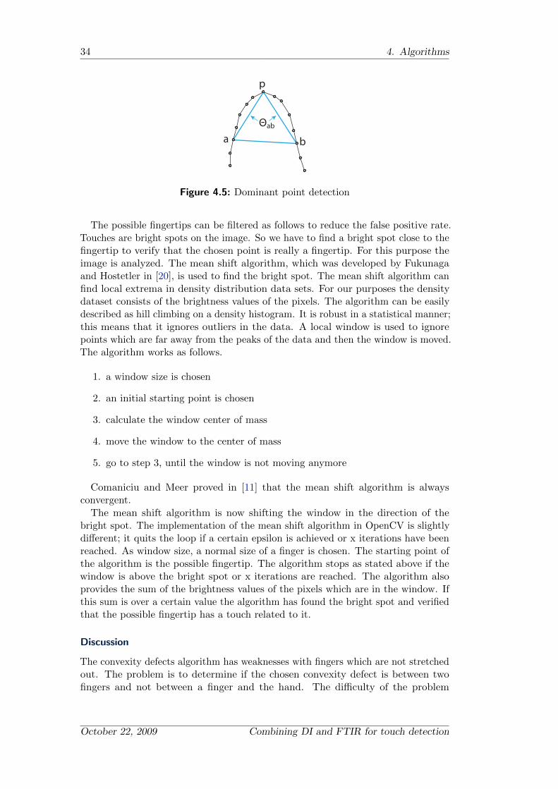
34 4. Algorithms
p
a b
Θab
Figure 4.5: Dominant point detection
The possible fingertips can be filtered as follows to reduce the false positive rate.Touches are bright spots on the image. So we have to find a bright spot close to thefingertip to verify that the chosen point is really a fingertip. For this purpose theimage is analyzed. The mean shift algorithm, which was developed by Fukunagaand Hostetler in [20], is used to find the bright spot. The mean shift algorithm canfind local extrema in density distribution data sets. For our purposes the densitydataset consists of the brightness values of the pixels. The algorithm can be easilydescribed as hill climbing on a density histogram. It is robust in a statistical manner;this means that it ignores outliers in the data. A local window is used to ignorepoints which are far away from the peaks of the data and then the window is moved.The algorithm works as follows.
1. a window size is chosen
2. an initial starting point is chosen
3. calculate the window center of mass
4. move the window to the center of mass
5. go to step 3, until the window is not moving anymore
Comaniciu and Meer proved in [11] that the mean shift algorithm is alwaysconvergent.
The mean shift algorithm is now shifting the window in the direction of thebright spot. The implementation of the mean shift algorithm in OpenCV is slightlydifferent; it quits the loop if a certain epsilon is achieved or x iterations have beenreached. As window size, a normal size of a finger is chosen. The starting point ofthe algorithm is the possible fingertip. The algorithm stops as stated above if thewindow is above the bright spot or x iterations are reached. The algorithm alsoprovides the sum of the brightness values of the pixels which are in the window. Ifthis sum is over a certain value the algorithm has found the bright spot and verifiedthat the possible fingertip has a touch related to it.
Discussion
The convexity defects algorithm has weaknesses with fingers which are not stretchedout. The problem is to determine if the chosen convexity defect is between twofingers and not between a finger and the hand. The difficulty of the problem
October 22, 2009 Combining DI and FTIR for touch detection
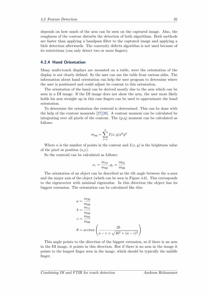
4.2 Feature Detection 35
depends on how much of the arm can be seen on the captured image. Also, theroughness of the contour disturbs the detection of both algorithms. Both methodsare faster than applying a bandpass filter to the captured image and applying ablob detection afterwards. The convexity defects algorithm is not used because ofits restrictions (can only detect two or more fingers).
4.2.4 Hand Orientation
Many multi-touch displays are mounted on a table, were the orientation of thedisplay is not clearly defined. So the user can use the table from various sides. Theinformation about hand orientation can help the user program to determine wherethe user is positioned and could adjust its content to this orientation.
The orientation of the hand can be derived mostly due to the arm which can beseen in a DI image. If the DI image does not show the arm, the user most likelyholds his arm straight up in this case fingers can be used to approximate the handorientation.
To determine the orientation the centroid is determined. This can be done withthe help of the contour moments [27][26]. A contour moment can be calculated byintegrating over all pixels of the contour. The (p,q) moment can be calculated asfollows:
mpq =n∑
i=1
I(x, y)xpyq
Where n is the number of points in the contour and I(x, y) is the brightness valueof the pixel at position (x,y).
So the centroid can be calculated as follows:
xc =m10
m00, yc =
m01
m00
The orientation of an object can be described as the tilt angle between the x-axesand the major axis of the object (which can be seen in Figure 4.6). This correspondsto the eigenvector with minimal eigenvalue. In this direction the object has itsbiggest extension. The orientation can be calculated like this:
a =m20
m00
b =m11
m00
c =m02
m00
θ = arctan
(2b
a− c+√
4b2 + (a− c)2
)
This angle points to the direction of the biggest extension, so if there is an armin the DI image, it points in this direction. But if there is no arm in the image itpoints to the longest finger seen in the image, which should be typically the middlefinger.
Combining DI and FTIR for touch detection Andreas Holzammer

36 4. Algorithms
Figure 4.6: Orientation angle theta, derived from central moments
The orientation vector needs to be corrected due to the fact that it could point tothe arm or to a finger. If the vector points to the direction of the arm the vectorneeds to reversed. To determine if the vector points to the arm, or to a finger a voteis done. If more then half of the finger vectors are pointing in the direction of theorientation vector the orientation is accurate; if not the vector needs to be rotatedby 180 degrees.
The vectors of the fingers can be derived from the centroid and the points of thefingertips. The orientation vector can be derived from the centroid and the angle θ.Angles between the orientation vector and the fingertip vectors are calculated withthe dot product of two vectors as follows:
cosλ =~a ·~b
|~a| ·∣∣∣~b∣∣∣
This calculates the smallest angle λ between these two vectors ~a,~b. This meansthe angle is either clockwise or counter clockwise. If the angle exceeds 90 degreesit is pointing in the opposite direction. If more than half of the fingertip vectorsdo not point in the same direction, the orientation vector needs to be reversed. Toreverse the orientation vector 180 degrees are added to the angle.
4.3 Post-processing
The detected features normally needs to be post-processed in the following manner.The objects that are detected in the individual images need to be tracked over thetime. Also, the position needs to be transformed from image space to the screencoordinate space.
4.3.1 Undistortion
Due to the fact that we use a fisheye lens for the camera, the pictures taken by thecamera come with a barrel distortion effect. For correcting this distortion a cameracalibration has to be done. One approach would be a linear approximation of thiseffect, but the effect is not linear, so only very small windows can be used. Thismeans the user needs a lot of calibration points in the calibration process to get asufficient calibration result.
To correct this effect sufficiently the camera calibration was done with the CameraCalibration Toolbox for Matlab [7]. For the process approximately 20 images of
October 22, 2009 Combining DI and FTIR for touch detection
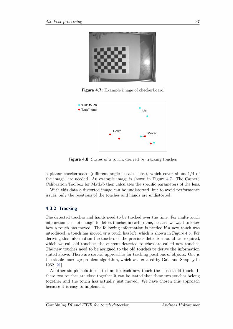
4.3 Post-processing 37
Figure 4.7: Example image of checkerboard
MovedDown
"Old" touch"New" touch Up
Figure 4.8: States of a touch, derived by tracking touches
a planar checkerboard (different angles, scales, etc.), which cover about 1/4 ofthe image, are needed. An example image is shown in Figure 4.7. The CameraCalibration Toolbox for Matlab then calculates the specific parameters of the lens.
With this data a distorted image can be undistorted, but to avoid performanceissues, only the positions of the touches and hands are undistorted.
4.3.2 Tracking
The detected touches and hands need to be tracked over the time. For multi-touchinteraction it is not enough to detect touches in each frame, because we want to knowhow a touch has moved. The following information is needed if a new touch wasintroduced, a touch has moved or a touch has left, which is shown in Figure 4.8. Forderiving this information the touches of the previous detection round are required,which we call old touches; the current detected touches are called new touches.The new touches need to be assigned to the old touches to derive the informationstated above. There are several approaches for tracking positions of objects. One isthe stable marriage problem algorithm, which was created by Gale and Shapley in1962 [21].
Another simple solution is to find for each new touch the closest old touch. Ifthese two touches are close together it can be stated that these two touches belongtogether and the touch has actually just moved. We have chosen this approachbecause it is easy to implement.
Combining DI and FTIR for touch detection Andreas Holzammer
38 4. Algorithms
The algorithm is altered for the matching of FTIR and DI, as follows. The user ismostly pushing with pressure, if he initially touches the screen and later on when hedrags the finger the pressure gets lesser. Because of this fact the FTIR technologyloses the track of the touch. The DI technology is very sensitive and produces ahigh false detection rate, which can be very disturbing to the user as Wigdor etal. [55] state. Therefore, only new FTIR touches are kept. If a new DI touch isdetected, which cannot be matched with an old touch, it is ignored.
4.3.3 Calibration
To transform the position of touches and hands from image space to the screenspace a calibration is needed. The screen coordinates are normalized to a scalebetween 0 and 1 in width and height, so that various display techniques can be usedfor the image displaying. For calibration purposes a calibration tool on the clientside is used to calculate the transformation. To do so, the user needs to push ninepoints. These nine points are sufficient because the barrel distortion effect is removedbeforehand. With these nine points a perspective transformation is calculated andthe touch points are transformed with that perspective transformation.
October 22, 2009 Combining DI and FTIR for touch detection
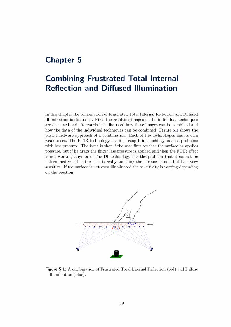
Chapter 5
Combining Frustrated Total InternalReflection and Diffused Illumination
In this chapter the combination of Frustrated Total Internal Reflection and DiffusedIllumination is discussed. First the resulting images of the individual techniquesare discussed and afterwards it is discussed how these images can be combined andhow the data of the individual techniques can be combined. Figure 5.1 shows thebasic hardware approach of a combination. Each of the technologies has its ownweaknesses. The FTIR technology has its strength in touching, but has problemswith less pressure. The issue is that if the user first touches the surface he appliespressure, but if he drags the finger less pressure is applied and then the FTIR effectis not working anymore. The DI technology has the problem that it cannot bedetermined whether the user is really touching the surface or not, but it is verysensitive. If the surface is not even illuminated the sensitivity is varying dependingon the position.
Figure 5.1: A combination of Frustrated Total Internal Reflection (red) and DiffuseIllumination (blue).
39
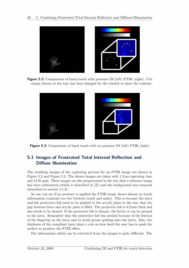
40 5. Combining Frustrated Total Internal Reflection and Diffused Illumination
Figure 5.2: Comparison of hand touch with pressure DI (left) FTIR (right). Col-ormap (shown at the top) has been changed for the window to show the contrast.
Figure 5.3: Comparison of hand touch with no pressure DI (left) FTIR (right)
5.1 Images of Frustrated Total Internal Reflection andDiffuse Illumination
The resulting images of the capturing process for an FTIR image are shown inFigure 5.2 and Figure 5.3. The shown images are taken with 1.2 ms capturing timeand 12 db gain. These images are also preprocessed in the way that a reference imagehas been subtracted (which is described in [3]) and the background was removed(described in section 4.1.3).
As one can see if no pressure is applied the FTIR image shows almost no touchinformation (contrast too low between touch and noise). This is because the latexand the protective foil need to be pushed to the acrylic plate in the way that thegap between latex and acrylic plate is filled. The projective foil is 0.2 mm thick andalso needs to be dented. If the protective foil is thinner, the better it can be pressedto the latex. Remember that the protective foil was needed because of the frictionof the fingertip on the latex and to avoid grease getting onto the latex. Also, thethickness of the compliant layer plays a role on how hard the user has to push thesurface to produce the FTIR effect.
The information which can be extracted from the images is quite different. The
October 22, 2009 Combining DI and FTIR for touch detection

5.2 Processing Pineline 41
Figure 5.4: Comparison of flat hand touch DI (left) FTIR (right)
Figure 5.5: Comparison of touches close together, DI (left) FTIR (right)
FTIR image illustrates the actual touches of the finger, but gives no informationabout how these touches belong together. The DI image illustrates the contour ofthe hands and some depth information by the gradients in the image.
Depth information also can be approximated by the brightness at a certain spotof the image. But these informations are very rough, because each material hasdifferent infrared reflection characteristics. The human skin reflects the infraredlight fairly good [58]. If the user wears a long shirt, a sweater or even a watch theimage looks very different.
If the hand is laid flat on the surface almost no information can be extracted fromthe FTIR image, as illustrated in Figure 5.4. Parts of the palm can be seen and afew fingers that are very dark. On the other hand, in the DI image the hand can beseen clearly.
When two touches are close together it is difficult to separate them from eachother in the DI image in contrast to the FTIR image; there the difference betweenthese two touches can be clearly seen (Figure 5.5). The human eye can determinethese touches, but the computer needs a few steps to detect the touches.
5.2 Processing Pineline
The processing pipelines for FTIR and DI are slightly different. For an FTIR setupthe captured image is preprocessed by subtracting the ambient light and background,
Combining DI and FTIR for touch detection Andreas Holzammer

42 5. Combining Frustrated Total Internal Reflection and Diffused Illumination
Ambient LightSubtraction
BackgroundRemoval
Blob Detection
Tracking
Transformation Application
Ambient LightSubtraction
BackgroundRemove
FingertipDetection
Transformation Application
Tracking
Figure 5.6: Normal FTIR Pipeline shown on the left, a normal DI Pipeline is shownon the right
Figure 5.7: left: Hand image with FTIR and DI LEDs on, right: Hand with FTIRand DI image multiplied
which was discussed in section 4.1. After this, bright spots are detected and then thecoordinates of these spots are post-processed to track the touches and transformedto match the screen coordinates. The transformation includes the undistortion andcalibration.
For a DI setup there are several pipeline models possible. The general pipelineorder is that the captured image is preprocessed with subtraction of ambient lightand background and then fingertips are extracted, as described in section 4.2.3.These coordinates are post-processed like in the FTIR pipeline. For detectingfingertips a bandpass filter can be applied and then bright spots can be detectedas fingertips. Another method is to evaluate the hand contour as described insection 4.2.3. Sample pipelines for FTIR and DI are illustrated in Figure 5.6.
5.3 Combination
One way of combining the FITR and the DI effect is described by Weiss et al.in 2008 [54]. They built a table on which the user can put silicone widgets, towork with and get a haptic feedback. They can change the labeling of the widgetsby changing the image projection to the silicone widgets, because they call them“Silicone ILluminated Active Peripherals” (SLAP). They have the FTIR and DILEDs switched on at same time. Their table cannot switch the individual LEDson and off at the same time, in contrast to ours that can be switched on and off
October 22, 2009 Combining DI and FTIR for touch detection
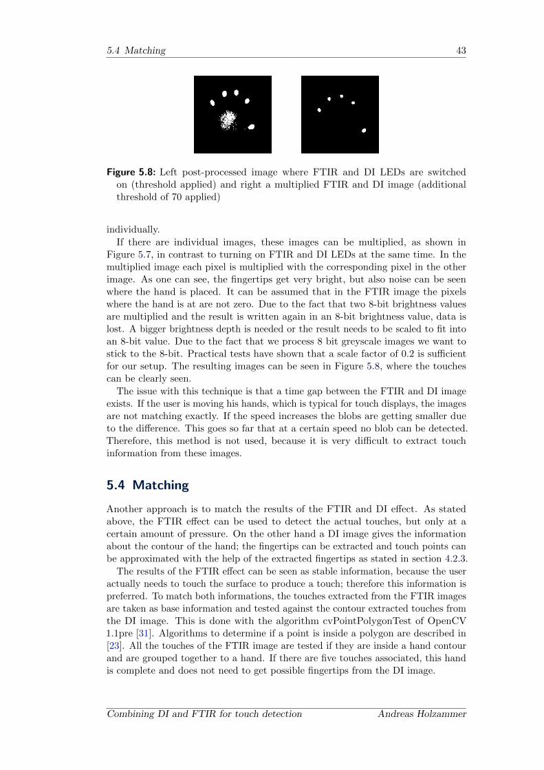
5.4 Matching 43
Figure 5.8: Left post-processed image where FTIR and DI LEDs are switchedon (threshold applied) and right a multiplied FTIR and DI image (additionalthreshold of 70 applied)
individually.
If there are individual images, these images can be multiplied, as shown inFigure 5.7, in contrast to turning on FTIR and DI LEDs at the same time. In themultiplied image each pixel is multiplied with the corresponding pixel in the otherimage. As one can see, the fingertips get very bright, but also noise can be seenwhere the hand is placed. It can be assumed that in the FTIR image the pixelswhere the hand is at are not zero. Due to the fact that two 8-bit brightness valuesare multiplied and the result is written again in an 8-bit brightness value, data islost. A bigger brightness depth is needed or the result needs to be scaled to fit intoan 8-bit value. Due to the fact that we process 8 bit greyscale images we want tostick to the 8-bit. Practical tests have shown that a scale factor of 0.2 is sufficientfor our setup. The resulting images can be seen in Figure 5.8, where the touchescan be clearly seen.
The issue with this technique is that a time gap between the FTIR and DI imageexists. If the user is moving his hands, which is typical for touch displays, the imagesare not matching exactly. If the speed increases the blobs are getting smaller dueto the difference. This goes so far that at a certain speed no blob can be detected.Therefore, this method is not used, because it is very difficult to extract touchinformation from these images.
5.4 Matching
Another approach is to match the results of the FTIR and DI effect. As statedabove, the FTIR effect can be used to detect the actual touches, but only at acertain amount of pressure. On the other hand a DI image gives the informationabout the contour of the hand; the fingertips can be extracted and touch points canbe approximated with the help of the extracted fingertips as stated in section 4.2.3.
The results of the FTIR effect can be seen as stable information, because the useractually needs to touch the surface to produce a touch; therefore this information ispreferred. To match both informations, the touches extracted from the FTIR imagesare taken as base information and tested against the contour extracted touches fromthe DI image. This is done with the algorithm cvPointPolygonTest of OpenCV1.1pre [31]. Algorithms to determine if a point is inside a polygon are described in[23]. All the touches of the FTIR image are tested if they are inside a hand contourand are grouped together to a hand. If there are five touches associated, this handis complete and does not need to get possible fingertips from the DI image.
Combining DI and FTIR for touch detection Andreas Holzammer
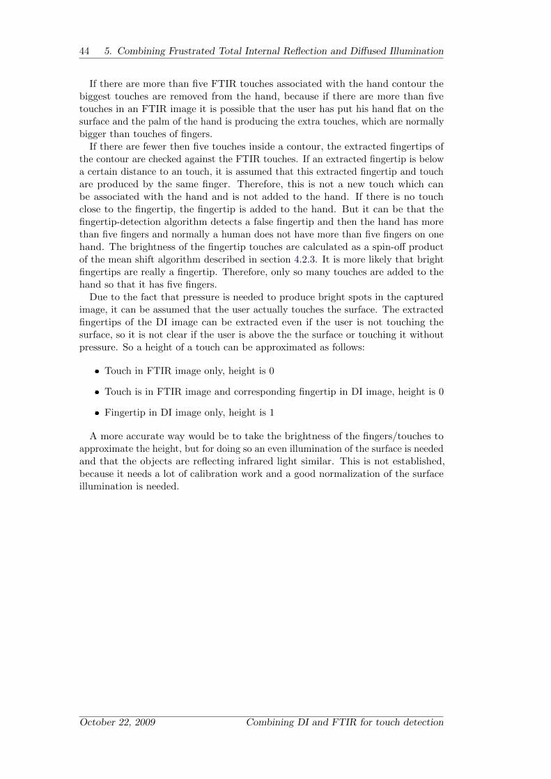
44 5. Combining Frustrated Total Internal Reflection and Diffused Illumination
If there are more than five FTIR touches associated with the hand contour thebiggest touches are removed from the hand, because if there are more than fivetouches in an FTIR image it is possible that the user has put his hand flat on thesurface and the palm of the hand is producing the extra touches, which are normallybigger than touches of fingers.
If there are fewer then five touches inside a contour, the extracted fingertips ofthe contour are checked against the FTIR touches. If an extracted fingertip is belowa certain distance to an touch, it is assumed that this extracted fingertip and touchare produced by the same finger. Therefore, this is not a new touch which canbe associated with the hand and is not added to the hand. If there is no touchclose to the fingertip, the fingertip is added to the hand. But it can be that thefingertip-detection algorithm detects a false fingertip and then the hand has morethan five fingers and normally a human does not have more than five fingers on onehand. The brightness of the fingertip touches are calculated as a spin-off productof the mean shift algorithm described in section 4.2.3. It is more likely that brightfingertips are really a fingertip. Therefore, only so many touches are added to thehand so that it has five fingers.
Due to the fact that pressure is needed to produce bright spots in the capturedimage, it can be assumed that the user actually touches the surface. The extractedfingertips of the DI image can be extracted even if the user is not touching thesurface, so it is not clear if the user is above the the surface or touching it withoutpressure. So a height of a touch can be approximated as follows:
Touch in FTIR image only, height is 0
Touch is in FTIR image and corresponding fingertip in DI image, height is 0
Fingertip in DI image only, height is 1
A more accurate way would be to take the brightness of the fingers/touches toapproximate the height, but for doing so an even illumination of the surface is neededand that the objects are reflecting infrared light similar. This is not established,because it needs a lot of calibration work and a good normalization of the surfaceillumination is needed.
October 22, 2009 Combining DI and FTIR for touch detection

Chapter 6
DIFTIRTracker
The software for an optical multi-touch device is the most important part, becausethis software is analyzing the captured images of the camera to extract the touchinformation. With the algorithms described in the last chapter an application can becreated to determine and track touches. By looking at some other tracking software,it comes clear that we want to develop our own software. In the Appendix is a shortoverview of tracking software developed by various authors. The DIFTIRTrackerwas developed to rapidly test all kinds of technologies and to be flexible in order tointegrate new functionalities. This software should process data from the hardwareand control the hardware in real-time. The idea for the software was to spliteverything into small parts (modules), so that the software can be easily extendedand most modules can be reused. All those parts should have the possibility todisplay what these modules are doing (show what happened to the image, or whatwas detected). These modules can be connected to each other in various ways; theonly limitation is that each input of a module has only one other connected module.There are three categories of modules: input, filter and output modules. Inputmodules get a datagram from an external source, e.g., a camera, video file, imagefile. Filter modules take data, process it and send it to the next module. Outputmodules send, save etc. a datagram. A datagram normally represents an image, butit is not restricted to image datagrams; also touch datagrams and even others canbe implemented. Each module is working in its own thread so that the applicationcan take advantage of multi-core systems and is very scalable.
Figure 6.1: DIFTIRTracker when it is started
45

46 6. DIFTIRTracker
Figure 6.2: Parts of the DIFTIRTracker
The DIFTIRTracker is written in C++ and uses the Qt framework [45] fromNokia. This combination is chosen because the application should run in real-timeand the software should be platform independent. The only reason why it is notplatform independent is the camera module, because the software developmentkit (SDK) from Point Grey [49] is not platform independent.
6.1 Graphical User Interface
The Graphical User Interface (GUI) consists of the following parts: diagram scene,module selection, properties window, action control, log window and menus as shownin Figure 6.2.
6.2 Pipeline
Due to the fact that every module is running in its own thread all the moduleshave to be synchronized. This is done by pipelining the modules. Each connectionbetween modules is represented by a ring buffer. If a module is done with itsprocessing of the datagram it puts the resulting datagram into the ring buffer, wakesthe next module in the pipeline. This next module takes the datagram out of thering buffer and processes it and puts it again in the next ring buffer and so on. Adatagram can only be sent into one direction, but a circle connection can be builtfor feedback. The modules can wait for datagrams in a ring buffer or can determineif there is any datagram in the ring buffer.
October 22, 2009 Combining DI and FTIR for touch detection

6.3 Network Interface 47
Hand Touch Touch Touch Touch Touch
0 1 2 3 4 5
...
...
Figure 6.3: Hand TUIO Package
6.3 Network Interface
The touch server sends the touch/hand information through the network. To servemore applications the TUIO protocol described by Kaltenrunner et al. in [35] is usedto transfer the data from the touch server to the client application. The protocol hasbeen implemented in various platforms and programming languages like Java, C++,PureData, Max/MSP, SuperCollider and Flash. The protocol uses User DatagramProtocol (UDP) packets to send the data through the network, which is faster thanthe Transmission Control Protocol (TCP), but not as reliable. It is very importantthat the latency is low, because the user wants to interact with the computer andthey will think if the reaction of a touch is too slow that the touch was not recognizedand then repeat it. The TUIO protocol has two main types of data; the protocoldescribes touches and objects, but custom profiles can be implemented too.
There is a reference implementation of the TUIO protocol, which implements the2D touch and object profile of the protocol. Due to the fact that a hand can also beseen as an object, and objects in the TUIO protocol have a position, symbol ID anda angle, it matches the requirements we need for the hand. Objects can be used todescribe a hand’s position and orientation, which cannot be done with the touch,because it has no angle. But the hand has more information than a position andorientation, it has fingers that belong to the hand. A touch in the TUIO protocolhas no symbol ID, which can be set to produce a relation between the hand and thetouches, but objects have a symbol ID, so a finger is also described as an object. Apackage of a hand and fingers is introduced. Due to the fact that a normal humanhas five fingers the package needs six objects, a hand object and five finger objects.Figure 6.3 shows such a package. These packages are followed by each other, so itcan be derived which object is a hand and which are the corresponding fingers, bydividing the symbol ID by six, and examining the rest; 0 is the hand and 1 to 5 aretouches.
To use the multi-touch table with objects and hands together, the starting symbolID for hands is increased so as to not to interfere with other possible object symbolIDs. A integer with 32 bits is used for the symbol ID; therefore there are plenty ofIDs and not all IDs are needed for objects. A number of 1000 objects which can beused on the surface seems to be sufficient. All objects with a symbol ID above 1000belong to a hand, and hand IDs are reused if the hand leaves the surface, so thereshould be no ID overflow.
Combining DI and FTIR for touch detection Andreas Holzammer

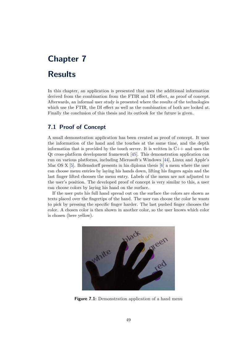
Chapter 7
Results
In this chapter, an application is presented that uses the additional informationderived from the combination from the FTIR and DI effect, as proof of concept.Afterwards, an informal user study is presented where the results of the technologieswhich use the FTIR, the DI effect as well as the combination of both are looked at.Finally the conclusion of this thesis and its outlook for the future is given.
7.1 Proof of Concept
A small demonstration application has been created as proof of concept. It usesthe information of the hand and the touches at the same time, and the depthinformation that is provided by the touch server. It is written in C++ and uses theQt cross-platform development framework [45]. This demonstration application canrun on various platforms, including Microsoft’s Windows [44], Linux and Apple’sMac OS X [5]. Bollensdorff presents in his diploma thesis [6] a menu where the usercan choose menu entries by laying his hands down, lifting his fingers again and thelast finger lifted chooses the menu entry. Labels of the menu are not adjusted tothe user’s position. The developed proof of concept is very similar to this, a usercan choose colors by laying his hand on the surface.
If the user puts his full hand spread out on the surface the colors are shown astexts placed over the fingertips of the hand. The user can choose the color he wantsto pick by pressing the specific finger harder. The last pushed finger chooses thecolor. A chosen color is then shown in another color, so the user knows which coloris chosen (here yellow).
Figure 7.1: Demonstration application of a hand menu
49

50 7. Results
d1 d2
Figure 7.2: Determination if the hand is a right or a left hand
To make the labels readable to the user they need to be adjusted to the userposition. If we only had the information of the touches this would be impossible.Also, the information that these touches are belonging to one hand is needed toprovide this kind of menu. The orientation of the hand is used to adjust the labelposition in the way that the user can read it. It makes no difference where the useris standing when they want to use the menu. The user can be in front or sidewaysof the table to use the menu. The label is also tilted by 45 degrees to reduce theoverlap of the labels.
Due to the fact that the fingers are not sorted by the touch server, the labels ofthe menu would be unsorted too. The user is very confused if he wants to go intothe menu and every time the menu is sorted differently. So the fingers need to besorted, that the user has the same menu each time he opens it up, by laying hishand down.
To sort the fingertips of a hand, the hand orientation is used to produce a vectorfrom the centroid in the direction of the arm. This can be done with the orientationprovided by the touch server by rotating the vector by 180 degrees. Vectors forthe fingertips can be created by taking the centroid and the coordinates of eachindividual fingertip. Afterwards the angles are calculated between the arm vectorand the fingertip vectors. Due to the fact that with the help of the dot product aminimal angle between two vectors can be calculated, the fingertips cannot be sortedby this angle. To calculate the clockwise angle, it is checked if the dot product hascalculated a clockwise angle or a counterclockwise angle. If it is a counterclockwiseangle, the angle is corrected. The result is sorted. Later on the fingertips can beused for the labeling, so that the user always has the same order of the labels in themenu.
It can be determined if the hand is a right or a left hand. A left hand has a thumbthat is pointing in the right direction as shown in Figure 7.2, and the right handthumb is pointing to the left. The thumb is also positioned closer to the wrist thanthe other fingers. So the thumb and the index finger have mostly a higher distancebetween each other than the pinky and the ring finger. If the fingers are sortedclockwise and the distance between the first and the second (d1) are greater thanbetween the last and the previous (d2) it is a right hand, and if not it is a left hand.Figure 7.2 shows a left hand, where the two distances are labeled d1 and d2.
Due to the fact that it is known which hand it is, the labels can be adjusted to
October 22, 2009 Combining DI and FTIR for touch detection

7.2 Informal User Study 51
this information. For a right hand the labels can be tilted to the right, and if it isa left hand the labels can be tilted to the left. It is also possible to show differentmenus for the right and the left hand, for example, with the right hand a color canbe chosen and with the left hand a brush size.
7.2 Informal User Study
We have presented various ways for detecting multiple touches. Users have to operatesuch multi-touch surfaces, therefore users can state if these technologies fit theirexpectations. A informal user study has been done to determine which technologyworks best for them. We hypothesized that the combination of the FTIR and DIeffect will be preferred by the users, because it uses the advantages of the FTIReffect and the DI effect.
The participants were asked to use Community Earth (shown in Figure 7.3),which is a multi-touch implementation of Nasa World Wind [2] written by Ang etal. [4]. Community earth shows a virtual globe where the user can pan, rotate, zoomand tilt the globe. The globe is panned with a touching finger, with two fingers theuser can zoom and rotate the globe and it can be tilted if the user uses three fingers,as shown in Figure 7.4.
Figure 7.3: Community Earth
Another application has been created to test the blob detection and tracking rateof the implemented technologies. A maze application is found sufficient enough forthat task, which is written in C++ with the QT framework of Nokia. The mazecan be solved with one or two fingers. To solve the maze the user has to pushthe starting circle (green) and has to drag his finger through the maze to the endpoint (blue). If the user is hitting the wall with his finger he has not completedthe maze and has to start over again. If the touch detection or the tracking fails,the touch is lost and the user has to start over again too. With two fingers theuser pushes the start circle with two fingers and drags them to the end point. Arestriction with two fingers is the distance between fingers, when the user exceedsthe maximum distance he has to start over again. Statistics over the successful andunsuccessful tries are presented in the upper left corner. The maze itself can be
Combining DI and FTIR for touch detection Andreas Holzammer

52 7. Results
drawn with this application too. The maze has been created to be easily solved andonly as big as it could be solved without changing the stand position. The mazeshould be easy to solve, because it is not the task for the users to solve the maze,they should test the touch detection and tracking. The size of the display is so bigthat the full screen cannot be reached from one standpoint; that is why the maze isnot created to fill the full screen.
Seven unpaid participants (six male and one female) in the age of 20 to 28 wereasked to participate in the informal user study. All users were right handed andtheir education level varied from high-school student to post-graduate degrees. Noneof the participants had experience with multi-touch devices.
The following five different processing pipelines were tested.
FTIR pipeline
DI with hand detection pipeline
DI with a bandpass filter pipeline
FTIR matched with DI with a bandpass filter pipeline
FTIR matched with DI with hand detection pipeline
The pipelines which were used, are shown in Figures 7.6 and 7.7. Ambient lightsubtraction is not used for pipelines that involve the DI technology, because most ofthe DI pipelines make heavy use of modules that need a great deal of performance,which makes the latency a little bit better.
The participants where asked to test three to four of those processing pipelineswith the Community Earth application and with the maze application. In theCommunity Earth application the users were first introduced to the applicationby showing the gestures illustrated by Figure 7.4 and later on they were asked tonavigate to their homes. Afterwards, with other pipelines, they should find otherplaces like New York, Paris etc. In the labyrinth application the users should try tosolve the labyrinth with one and two fingers. The participants were observed whiledoing their tasks and afterwards informally interviewed about their opinion on howwell each detection pipeline is working.
Almost all participants were comfortable with the multi-touch interface aftera short starting phase; only one had problems after a while with the navigation
Pan Zoom in Zoom out
Rotate Tilt
Figure 7.4: Gestures used by Community Earth, red circle indicates starting point
October 22, 2009 Combining DI and FTIR for touch detection
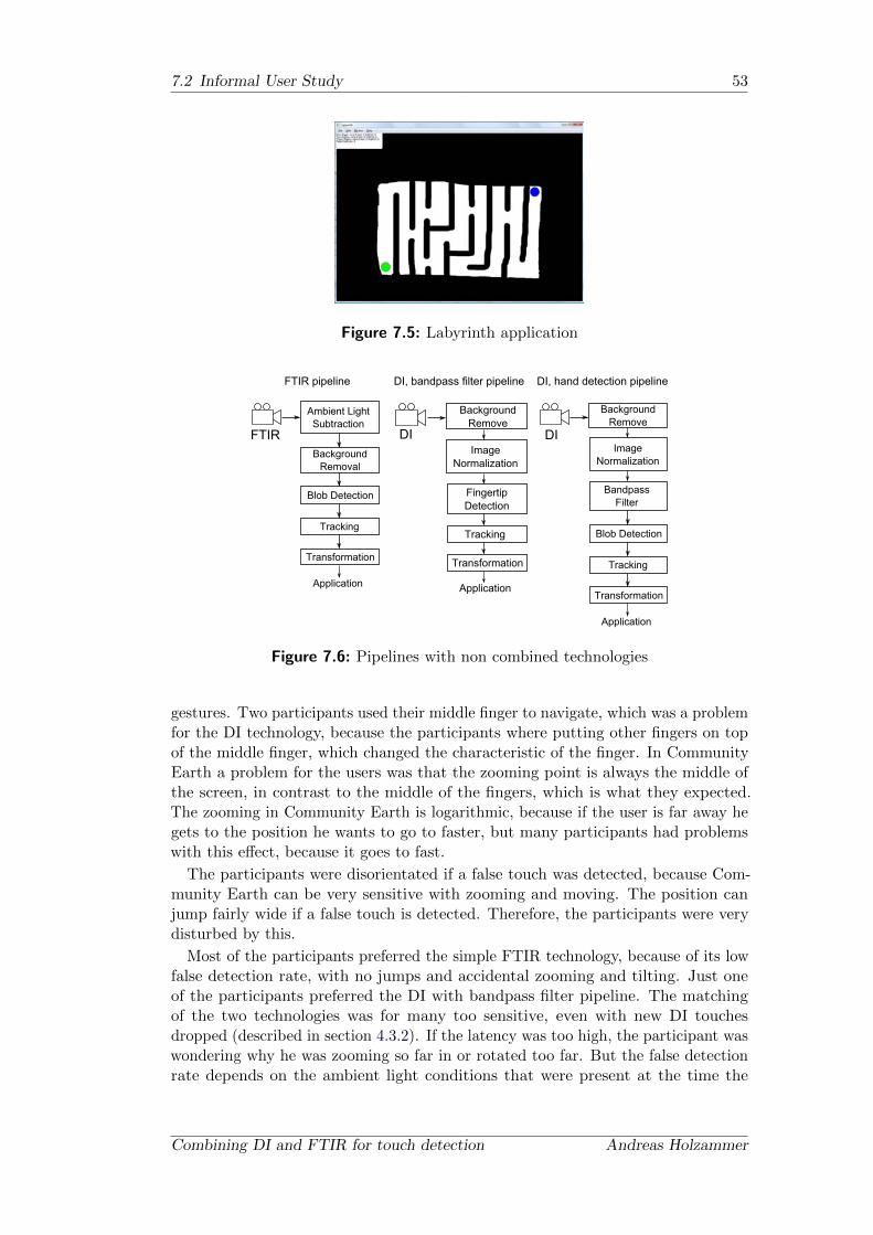
7.2 Informal User Study 53
Figure 7.5: Labyrinth application
Ambient LightSubtraction
BackgroundRemoval
Blob Detection
Tracking
Transformation
Application
FTIRImage
Normalization
BackgroundRemove
FingertipDetection
Transformation
Application
Tracking
DI
FTIR pipeline DI, bandpass filter pipeline DI, hand detection pipeline
BandpassFilter
Blob Detection
Tracking
Transformation
Application
DIImage
Normalization
BackgroundRemove
Figure 7.6: Pipelines with non combined technologies
gestures. Two participants used their middle finger to navigate, which was a problemfor the DI technology, because the participants where putting other fingers on topof the middle finger, which changed the characteristic of the finger. In CommunityEarth a problem for the users was that the zooming point is always the middle ofthe screen, in contrast to the middle of the fingers, which is what they expected.The zooming in Community Earth is logarithmic, because if the user is far away hegets to the position he wants to go to faster, but many participants had problemswith this effect, because it goes to fast.
The participants were disorientated if a false touch was detected, because Com-munity Earth can be very sensitive with zooming and moving. The position canjump fairly wide if a false touch is detected. Therefore, the participants were verydisturbed by this.
Most of the participants preferred the simple FTIR technology, because of its lowfalse detection rate, with no jumps and accidental zooming and tilting. Just oneof the participants preferred the DI with bandpass filter pipeline. The matchingof the two technologies was for many too sensitive, even with new DI touchesdropped (described in section 4.3.2). If the latency was too high, the participant waswondering why he was zooming so far in or rotated too far. But the false detectionrate depends on the ambient light conditions that were present at the time the
Combining DI and FTIR for touch detection Andreas Holzammer

54 7. Results
FTIR matched with DI with hand detection pipeline
BackgroundRemove
FTIR
BackgroundRemove
FingertipDetection
DI
Match Blobsand Hand
Tracking
Transformation
Application
BackgroundRemove
Blob DetectionFTIR
BackgroundRemove
BandpassFilter
Blob Detection
DI
Match Blobs
Tracking
Transformation
Application
FTIR matched with DI with a bandpass filter pipeline
ImageNormalization
ImageNormalization
Blob Detection
Figure 7.7: Pipelines with combined technologies
participants were performing the informal user study.
In the labyrinth applications users had problems with the hand detection pipeline,because they did not spread their fingers far enough or were touching from above sothat the finger cannot be clearly seen in the DI image.
Overall it can be said that the participants preferred technologies which haveless false detection and are accepting less detection sensitivity. In contrast to thehypothesize, which stated that the combination of the FTIR and DI effect willmatch their expectations, the single FTIR technology worked best for them. Thishad several purposes, like the longer latency of the combined technologies and thehigher false detection rate.
7.3 Conclusion
We have presented a several methods to combine the Frustrated Total InternalReflection and Diffused Illumination effect. Therefore, we gave an overview ofmulti-touch technologies and discussed why FTIR and DI should be combined. Nextwe looked at the hardware setup, which is needed for the combination and discussedwhy we took these hardware parts. After all the algorithms have been presented,which are needed for the preprocessing, feature detection and the post-processingof the data which is captured by the camera. The following part of the thesisdealt with the combination of the informations gathered by the Frustrated TotalInternal Reflection effect and the Diffused Illumination information. It was discussedwhether it is better to combine the information in the pre- or the post-processingstep. An application for rapid testing and debugging was developed to detect andtrack touches for various optical technologies. This easy-to-use application can evenbe used by people with no programming skills, because the user can visually combinestandard modules. To test the developed methods for combing the technologies, asmall informal user study has been performed. Seven participants were asked touse the multi-touch table with two applications, Community Earth and a self-built
October 22, 2009 Combining DI and FTIR for touch detection
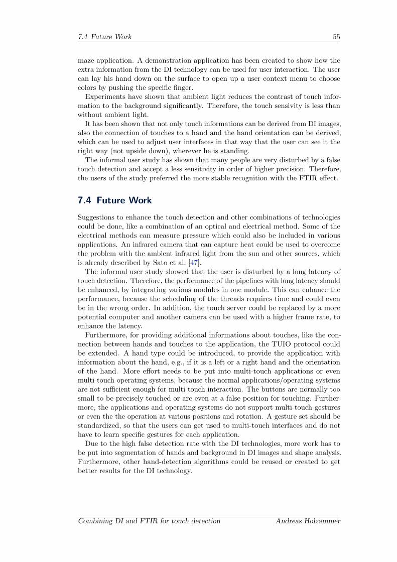
7.4 Future Work 55
maze application. A demonstration application has been created to show how theextra information from the DI technology can be used for user interaction. The usercan lay his hand down on the surface to open up a user context menu to choosecolors by pushing the specific finger.
Experiments have shown that ambient light reduces the contrast of touch infor-mation to the background significantly. Therefore, the touch sensivity is less thanwithout ambient light.
It has been shown that not only touch informations can be derived from DI images,also the connection of touches to a hand and the hand orientation can be derived,which can be used to adjust user interfaces in that way that the user can see it theright way (not upside down), wherever he is standing.
The informal user study has shown that many people are very disturbed by a falsetouch detection and accept a less sensitivity in order of higher precision. Therefore,the users of the study preferred the more stable recognition with the FTIR effect.
7.4 Future Work
Suggestions to enhance the touch detection and other combinations of technologiescould be done, like a combination of an optical and electrical method. Some of theelectrical methods can measure pressure which could also be included in variousapplications. An infrared camera that can capture heat could be used to overcomethe problem with the ambient infrared light from the sun and other sources, whichis already described by Sato et al. [47].
The informal user study showed that the user is disturbed by a long latency oftouch detection. Therefore, the performance of the pipelines with long latency shouldbe enhanced, by integrating various modules in one module. This can enhance theperformance, because the scheduling of the threads requires time and could evenbe in the wrong order. In addition, the touch server could be replaced by a morepotential computer and another camera can be used with a higher frame rate, toenhance the latency.
Furthermore, for providing additional informations about touches, like the con-nection between hands and touches to the application, the TUIO protocol couldbe extended. A hand type could be introduced, to provide the application withinformation about the hand, e.g., if it is a left or a right hand and the orientationof the hand. More effort needs to be put into multi-touch applications or evenmulti-touch operating systems, because the normal applications/operating systemsare not sufficient enough for multi-touch interaction. The buttons are normally toosmall to be precisely touched or are even at a false position for touching. Further-more, the applications and operating systems do not support multi-touch gesturesor even the the operation at various positions and rotation. A gesture set should bestandardized, so that the users can get used to multi-touch interfaces and do nothave to learn specific gestures for each application.
Due to the high false detection rate with the DI technologies, more work has tobe put into segmentation of hands and background in DI images and shape analysis.Furthermore, other hand-detection algorithms could be reused or created to getbetter results for the DI technology.
Combining DI and FTIR for touch detection Andreas Holzammer


Chapter 8
Appendix
8.1 Several Spectra of Infrared Bandpass Filters
Here a selection of transmission curves of infrared filters are printed.
Figure 8.1: Spectrum of one overexposed photo negative. Figure taken from [40]
Figure 8.2: Spectrum of two overexposed photo negative. Figure taken from [40]
57

58 8. Appendix
Figure 8.3: Spectrum of one floppy disk. Figure taken from [40]
Figure 8.4: Spectrum of two floppy disks. Figure taken from [40]
October 22, 2009 Combining DI and FTIR for touch detection

8.2 Projector list 59
8.2
Pro
ject
or
list
Manufactu
rer
Model
Projection
System
NativeReso
lution
Brightn
ess
Contrast
Ratio
Projection
lens
Throw
Ratio
Acer
S1200
DLP
1024x768
2500Lumen
2000:1
F=
2.6,f=
6.97mm
0.60:1
Optoma
EX525ST
DLP
1024x768
2500Lumen
2500:1
F=
2.59,f=
6.97mm
@0,73m
0.60:1
3M
SCP740
DLP
1280x800
2600Lumen
1600:1
F=
2.5
0.69:1
3M
DMS700
DLP
1024x768
1500Lumen
1200:1
0.60:1
NEC
WT610
DLP
1024x768
3500Lumen
3500:1
F=3.5,f=14.9mm
0.063:1
Optoma(L
ense)
EP-780
DLP
1024x768
4000Lumen
3000:1
1.66–2.0:1
Optoma(L
ense)
EP-782
DLP
1024x768
4700Lumen
3000:1
F/2.522.79,f=22.5527.06mm
1.3
–1.57:1
Optoma(L
ense)
EP-776
DLP
1024x768
4300Lumen
3000:1
F/2.522.79,f=22.5527.06mm
1.3
–1.57:1
Tosh
iba
EX-20
DLP
1024x768
2300Lumen
2000:1
F=
2,6
/f=
8,37
0.56:1
3M
SCP717
DLP
1024x768
3000Lumen
1600:1
F2.5
0.68:1
Hitach
iCP-A
100
LCD
1024x768
2500Lumen
400:1
0.28:1
Sanyo
PLC-X
L51
LCD
1024x768
2700Lumen
1200:1
0.039:1
Ben
QMP522ST
DLP
1024x768
2000Lumen
1000:1
F=2,5
mm
f=10mm
0.9:1
Manufactu
rer
Model
Projection
Screen
Size
Projection
Dista
nce
Lam
plifetim
eDista
nceforourta
ble
Acer
S1200
4.15@2m
or2.082@1m
0.5m
–3.7m
4000h(E
CO)/3000h(B
rightMode)
0.72m
Optoma
EX525ST
1.04m
–7.72m
0.5m
–3.7m
4000h(E
CO)/3000h(B
rightMode)
0.72m
3M
SCP740
1.27m
–2.48m
0.9m
–1.49m
3000h(E
CO)/2000h(B
rightMode)
0.828m
3M
DMS700
1.02m
–2.54m
0.5m
–1.25m
3000h(E
CO)/2000h(B
rightMode)
0.72m
NEC
WT610
1.016m@64mm
–2.032m@461mm
0.064m
–0.659m
4000h(E
CO)/3000h(B
rightMode)
0.1m
Optoma(L
ense)
EP-780
1.2m
–12m
3000h(E
CO)/2000h(B
rightMode)
1.992m
Optoma(L
ense)
EP-782
0.79m
–7.97m
1.2m
–10m
3000h(E
CO)/2000h(B
rightMode)
1.56m
Optoma(L
ense)
EP-776
0.79m
–7.97m
1.2m
–10m
3000h(E
CO)/2000h(B
rightMode)
1.56m
Tosh
ibaEX-20
0.6m
-7.m
0.5m
–1.5m
3000h(E
CO)/2000h(B
rightMode)
0.67m
3M
SCP717
1.5m
–2.5m
1.4m
–2.1m
3000h(E
CO)/2000h(B
rightMode)
0.828m
Hitach
iCP-A
100
0.42m
Sanyo
PLC-X
L51
-0.04m
Ben
QMP522ST
0.69m
–7.53m
0.5m
–5.5m
4000h(E
CO)/3000h(B
rightMode)
1.35m
Combining DI and FTIR for touch detection Andreas Holzammer

60 8. Appendix
8.3 Software
In this section a few touch and fiducial marker tracking applications are presentedto give an overview of what has already been done.
8.3.1 Community Core Vision (CCV)
Community Core Vision was created by the NUI Group community [22]. It waspreviously called tbeta, but before the source code of the software was released theyrenamed it. It is platform independent. CCV is based on OpenFrameworks [17], so itshould be easy to extend. It has support for various cameras and various multi-touchlighting techniques: FTIR, DI, DSI and LLP. Touching data is served to clientapplications through TUIO/OSC. Figure 8.5 shows a screenshot from CommunityCore Vision.
Figure 8.5: Community Core Vision (CCV)
8.3.2 CG Tracker
The CG Tracker from the Technical University of Berlin was first created as partof a project in the winter semester of 2007/08. Afterwards Stefan Elstner wrote agraphical user interface(GUI) as part of his master thesis [16] for the tracker. Thetracker was designed for the FTIR technique. It uses its own, newly created networkprotocol to serve as a multi-touch application. This tracker also tracked patternsof a display, which is placed on top of the table. This software is hard to extend,because it makes heavy use of the Windows application programming interface.
October 22, 2009 Combining DI and FTIR for touch detection

8.3 Software 61
Figure 8.6: CG Tracker, which was developed by a project at the Technical Univer-sity Berlin and Stephan Elstner
8.3.3 reacTIVision
Figure 8.7: ReacTIVision in action. Picture taken from their website [39]
ReacTIVision has been developed by Martin Kaltenbrunner and Ross Bencina atthe Music Technology Group at the Universitat Pompeu Fabra in Barcelona, Spain.It was developed for the reacTable project, which has already been described inthe related work section. It is an open-source, cross-platform computer visionframework to track fiducial markers attached to physical objects, as well as touchingfingers. It can be used with various cameras. Due to the fact that the softwaretracks fiducial markers, it can only handle optical technologies that support fiducial
Combining DI and FTIR for touch detection Andreas Holzammer
62 8. Appendix
markers, like DI and DSI. ReacTIVision implements the TUIO protocol, so allsupporting applications can be used.
8.3.4 Touchlib
Touchlib is a library for creating multi-touch interaction surfaces. It is written inC++, works only with Windows, will interact with most types of webcams and hasno graphical user interface. The user can build his own touch tracking applicationfairly easily due to the simple programming interface. Touchlib communicatesthrough the TUIO protocol with various multi-touch applications.
October 22, 2009 Combining DI and FTIR for touch detection

VII
Bibliography
[1] Acer. http://www.acer.com, accessed on 09/26/2009 12:00AM.
[2] National Aeronautics and Space Administration. World wind. http://worldwind.
arc.nasa.gov/java/, accessed on 10/09/2009 3:30PM.
[3] Marc Alexa, Bjorn Bollensdorff, Ingo Bressler, Stefan Elstner, Uwe Hahne, NinoKettlitz, Norbert Lindow, Robert Lubkoll, Ronald Richter, Claudia Stripf, SebastianSzczepanski, Karl Wessel, and Carsten Zander. Touch sensing based on ftir in thepresence of ambient light. techreport, Technical University of Berlin, 2008.
[4] Linus Ang, Charles Lo Taha Bintahir, and Zhen Zhang Pat King. Community earth.http://nuicode.com/projects/earth, accessed on 10/09/2009 3:30PM.
[5] Apple. Mac os x. http://www.apple.com/macosx/, accessed on 09/24/2009 3:15PM.
[6] Bjorn Bollensdorff. Multitouch navigation and manipulation of 3d objects. Master’sthesis, TU-Berlin, 2009.
[7] Jean-Yves Bouguet. Camera calibration toolbox for matlab. http://www.vision.
caltech.edu/bouguetj/calib_doc/, accessed on 10/01/2009 9:15PM.
[8] Bill Buxton. http://www.billbuxton.com/multitouchOverview.html, accessed on08/06/2009 3:00PM.
[9] W. Buxton and B. Myers. A study in two-handed input. SIGCHI Bull., 17(4):321–326,1986.
[10] Nintendo Co. Ltd. nintendo ds. http://www.nintendo.com/ds, accessed on09/22/2009 3:00PM.
[11] D. Comaniciu and P. Meer. Mean shift analysis and applications. In Computer Vision,1999. The Proceedings of the Seventh IEEE International Conference on, volume 2,pages 1197–1203 vol.2, 1999.
[12] Computar. http://computarganz.com/, accessed on 09/26/2009 12:00AM.
[13] Paul Dietz and Darren Leigh. Diamondtouch: a multi-user touch technology. In UIST’01: Proceedings of the 14th annual ACM symposium on User interface software andtechnology, pages 219–226, New York, NY, USA, 2001. ACM.
[14] Rick Downs. Using resistive touch screens for human/machine interface. Technicalreport, Texas Instruments Incorporated, 2005.
[15] Florian Echtler, Manuel Huber, and Gudrun Klinker. Shadow tracking on multi-touchtables. In AVI ’08: Proceedings of the working conference on Advanced visual interfaces,pages 388–391, New York, NY, USA, 2008. ACM.
[16] Stefan Elstner. Combining pen and multi-touch displays for focus+context interaction.Master’s thesis, TU-Berlin, 2009.
[17] Zach Lieberman et al. openframeworks. http://www.openframeworks.cc, accessedon 09/29/2009 4:30PM.
[18] Sony Computer Entertainment Europe. Playstation eye. http://en.playstation.com,accessed on 10/04/2009 10:30AM.
Combining DI and FTIR for touch detection Andreas Holzammer
VIII Bibliography
[19] David A. Forsyth and Jean Ponce. Computer Vision: A Modern Approach. PrenticeHall, us ed edition, August 2002.
[20] K. Fukunaga and L. Hostetler. The estimation of the gradient of a density function,with applications in pattern recognition. Information Theory, IEEE Transactions on,21(1):32–40, Jan 1975.
[21] D. Gale and L. S. Shapley. College admissions and the stability of marriage. TheAmerican Mathematical Monthly, 69(1):9–15, 1962.
[22] NUI GROUP. http://nuigroup.com/, accessed on 09/26/2009 11:00AM.
[23] Eric Haines. Point in polygon strategies. pages 24–46, 1994.
[24] Jefferson Y. Han. Low-cost multi-touch sensing through frustrated total internalreflection. In UIST ’05: Proceedings of the 18th annual ACM symposium on Userinterface software and technology, pages 115–118, New York, NY, USA, 2005. ACMPress.
[25] Jordan Hochenbaum and Owen Vallis. Bricktable. http://flipmu.com/work/
bricktable/, accessed on 10/05/2009 9:45AM.
[26] Alexander Hornberg. Handbook of Machine Vision. Wiley-VCH, 2006.
[27] Ming-Kuei Hu. Visual pattern recognition by moment invariants. Information Theory,IRE Transactions on, 8(2):179–187, February 1962.
[28] Apple Inc. iphone. http://www.apple.com/iphone/, accessed on 10/05/2009 3:00PM.
[29] Google Inc. Google trends. http://www.google.com/trends, accessed on 09/26/200911:00AM.
[30] Rosco Laboratories Inc. http://www.rosco.com/us/corporate/index.asp, accessedon 09/27/2009 3:00PM.
[31] Intel and Willow Garage. Opencv. http://opencv.willowgarage.com/wiki/, ac-cessed on 09/23/2009 2:00PM.
[32] Shahram Izadi, Steve Hodges, Stuart Taylor, Dan Rosenfeld, Nicolas Villar, Alex Butler,and Jonathan Westhues. Going beyond the display: a surface technology with anelectronically switchable diffuser. In UIST ’08: Proceedings of the 21st annual ACMsymposium on User interface software and technology, pages 269–278, New York, NY,USA, 2008. ACM.
[33] Benjamin Walther-Franks Jens Teichert, Marc Herrlich, Lasse Schwarten, SebastianFeige, Markus Krause, and Rainer Malaka. Advancing large interactive surfaces for usein the real world. Technical report, Digital Media Group, TZI, University of Bremen,2009.
[34] Sergi Jorda. Interactive music systems for everyone: Exploring visual feedback as away for creating more intuitive, efficient and learnable instruments. In Proceedings ofthe Stockholm Music Acoustics Conference (SMAC 03), Stockholm, Sweden, 2003.
[35] Martin Kaltenbrunner, Till Bovermann, Ross Bencina, and Enrico Costanza. Tuio - aprotocol for table based tangible user interfaces. In Proceedings of the 6th InternationalWorkshop on Gesture in Human-Computer Interaction and Simulation (GW 2005),Vannes, France, 2005.
[36] Sung K. Kang, Mi Y. Nam, and Phill K. Rhee. Color based hand and finger detec-tion technology for user interaction. Hybrid Information Technology, InternationalConference on, 0:229–236, 2008.
October 22, 2009 Combining DI and FTIR for touch detection
Bibliography IX
[37] Jong-Min Kim and Woong-Ki Lee. Hand shape recognition using fingertips. In FSKD’08: Proceedings of the 2008 Fifth International Conference on Fuzzy Systems andKnowledge Discovery, pages 44–48, Washington, DC, USA, 2008. IEEE ComputerSociety.
[38] Kenrick Kin, Maneesh Agrawala, and Tony DeRose. Determining the benefits ofdirect-touch, bimanual, and multifinger input on a multitouch workstation. In GI ’09:Proceedings of Graphics Interface 2009, pages 119–124, Toronto, Ont., Canada, Canada,2009. Canadian Information Processing Society.
[39] R. Bencina M. Kaltenbrunner. reactivision. http://reactivision.sourceforge.
net/, accessed on 09/27/2009 6:00PM.
[40] Madian. Spectral analysis of ir leds and filters. http://nuigroup.com/forums/
viewthread/6458/, accessed on 10/11/2009 12:30PM.
[41] Shahzad Malik and Joe Laszlo. Visual touchpad: a two-handed gestural input device.In ICMI ’04: Proceedings of the 6th international conference on Multimodal interfaces,pages 289–296, New York, NY, USA, 2004. ACM.
[42] Nobuyuki Matsushita and Jun Rekimoto. Holowall: designing a finger, hand, body, andobject sensitive wall. In UIST ’97: Proceedings of the 10th annual ACM symposiumon User interface software and technology, pages 209–210, New York, NY, USA, 1997.ACM.
[43] Microsoft. Surface. http://www.microsoft.com/surface/, accessed on 09/29/20093:00PM.
[44] Microsoft. Windows. http://www.microsoft.com/windows/, accessed on 09/24/20093:15PM.
[45] Nokia. Qt. http://qt.nokia.com/, accessed on 09/24/2009 3:15PM.
[46] Nolan. Peau productions. http://peauproductions.com/diff.html, accessed on10/04/2009 11:30AM.
[47] K. Oka, Y. Sato, and H. Koike. Real-time fingertip tracking and gesture recognition.Computer Graphics and Applications, IEEE, 22(6):64–71, Nov/Dec 2002.
[48] Osram. http://www.osram.com, accessed on 09/26/2009 12:00AM.
[49] Inc. Point Grey Research. http://www.ptgrey.com/, accessed on 09/26/200911:00AM.
[50] Ilya Rosenberg and Ken Perlin. The unmousepad: an interpolating multi-touch force-sensing input pad. ACM Trans. Graph., 28(3):1–9, 2009.
[51] Johannes Schoning, Peter Brandl, Florian Daiber, Florian Echtler, Otmar Hilliges,Jonathan Hook, Markus Lochtefeld, Nima Motamedi, Laurence Muller, Patrick Olivier,Tim Roth, and Ulrich von Zadow. Multi-touch surfaces: A technical guide. techreport,Technical University of Munich, 2008.
[52] The Imaging Source. Dmk 21bf04. http://www.theimagingsource.com/de_
DE/products/cameras/firewire-ccd-mono/dmk21bf04/, accessed on 10/04/200910:30AM.
[53] Midwest Optical Systems. Machine vision filter. http://www.midopt.com/, accessedon 09/26/2009 12:00AM.
[54] Malte Weiss, Julie Wagner, Yvonne Jansen, Roger Jennings, Ramsin Khoshabeh,James D. Hollan, and Jan Borchers. Slap widgets: Bridging the gap between virtualand physical controls on tabletops. In CHI ’09: Proceeding of the twenty-seventh annualSIGCHI conference on Human factors in computing systems, New York, NY, USA,2009. ACM.
Combining DI and FTIR for touch detection Andreas Holzammer
X Bibliography
[55] D. Wigdor, M. Cronin S. Williams, K. White R. Levy, M. Mazeev, and H. Benko.Ripples: Utilizing per-contact visualizations to improve user interaction with touchdisplays system. In UIST ’09: Proceedings of the 22nd annual ACM symposium onUser interface software and technology, 2009.
[56] Ying Wu, Ying Shan, Zhengyou Zhang, Zhengyou Zhang Y, and Steven Shafer. Visualpanel: From an ordinary paper to a wireless and mobile input device, 2000.
[57] Duan-Duan Yang, Lian-Wen Jin, and Jun-Xun Yin. An effective robust fingertipdetection method for finger writing character recognition system. Machine Learningand Cybernetics, 2005. Proceedings of 2005 International Conference on, 8:4991–4996Vol. 8, Aug. 2005.
[58] Hongqin Yang, Shusen Xie, Hui Li, and Zukang Lu. Determination of human skinoptical properties in vivo from reflectance spectroscopic measurements. Chin. Opt.Lett., 5(3):181–183, 2007.
[59] Zhiwei Zhu, Kikuo Fujimura, and Qiang Ji. Real-time eye detection and tracking undervarious light conditions. In ETRA ’02: Proceedings of the 2002 symposium on Eyetracking research & applications, pages 139–144, New York, NY, USA, 2002. ACM.
October 22, 2009 Combining DI and FTIR for touch detection
Related Documents