Mathey Dearman Catalog
Mar 26, 2016
Catalog of all pipe cutting and beveling machines, pipe alignment and reforming clamps, welding electrode and flux ovens, and pipefitter's tools that are apart of the Mathey Dearman product line.
Welcome message from author
This document is posted to help you gain knowledge. Please leave a comment to let me know what you think about it! Share it to your friends and learn new things together.
Transcript
SEPT 2009
P i p e C u t t i n g & A l i g n i n g S y s t e m s f o r t h e W e l d e r a n d P i p e F i t t e r
2
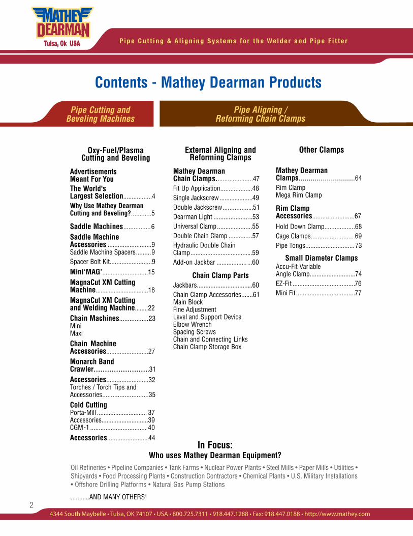
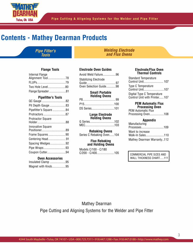
Contents - Mathey Dearman Products
In Focus: Who uses Mathey Dearman Equipment?
Oil Refineries • Pipeline Companies • Tank Farms • Nuclear Power Plants • Steel Mills • Paper Mills • Utilities • Shipyards • Food Processing Plants • Construction Contractors • Chemical Plants • U.S. Military Installations • Offshore Drilling Platforms • Natural Gas Pump Stations
...........AND MANY OTHERS!
External Aligning and Reforming Clamps
Mathey Dearman Chain Clamps......................47Fit Up Application...................48Single Jackscrew ....................49Double Jackscrew..................51Dearman Light .......................53Universal Clamp.....................55Double Chain Clamp ..............57Hydraulic Double Chain Clamp.....................................59Add-on Jackbar .................. ...60
Chain Clamp PartsJackbars.................................60Chain Clamp Accessories.......61 Main Block Fine Adjustment Level and Support Device Elbow Wrench Spacing Screws Chain and Connecting Links Chain Clamp Storage Box
Other Clamps
Mathey Dearman Clamps............................64Rim Clamp Mega Rim Clamp
Rim Clamp Accessories.........................67Hold Down Clamp..................68Cage Clamps..........................69Pipe Tongs.............................73
Small Diameter ClampsAccu-Fit Variable Angle Clamp...........................74EZ-Fit .....................................76Mini Fit ...................................77
Oxy-Fuel/Plasma Cutting and Beveling
Advertisements Meant For YouThe World's Largest Selection.................4Why Use Mathey Dearman Cutting and Beveling?............5
Saddle Machines................6Saddle Machine Accessories ..........................9Saddle Machine Spacers.........9Spacer Bolt Kit.........................9
Mini‘MAG’...........................15MagnaCut XM Cutting Machine................................18MagnaCut XM Cutting and Welding Machine........22Chain Machines.................23Mini MaxiChain Machine Accessories.........................27Monarch Band Crawler.........................31Accessories.........................32Torches / Torch Tips and Accessories...........................35
Cold CuttingPorta-Mill .............................. 37 Accessories............................39 CGM-1 ................................. 40Accessories........................44
Pipe Cutting and Beveling Machines
Pipe Aligning / Reforming Chain Clamps
3
P i p e C u t t i n g & A l i g n i n g S y s t e m s f o r t h e W e l d e r a n d P i p e F i t t e r
4344 South Maybelle • Tulsa, OK 74107 • USA • 800.725.7311 • 918.447.1288 • Fax: 918.447.0188 • http://www.mathey.com
Electrode Oven GuidesAvoid Weld Failure................96Stabilizing Electrode Guide ...................................97Oven Selection Guide............98
Small Portable Holding Ovens
P8.........................................99P15......................................100DS Series.............................101
Large Electrode Holding Ovens
G Series................................102 MEC......................................103
Rebaking OvensSeries C Rebaking Oven......104
Flux Rebaking and Holding Ovens
Models C/100 - C/180 C/200 - C/400......................105
Electrode/Flux Oven Thermal Controls
Standard Temperature Control Unit......................... 107Type C Temperature Control Unit..........................107Digital Type C Temperature Control Unit with Printer......107
PEM Automatic Flux Processing Oven
PEM Automatic Flux Processing Oven..................108
AppendixManufacturing Processes.............................109Want to increase Walk-In Sales.......................110Mathey Dearman Warranty...112
COMMERCIAL PIPE SIZES AND WALL THICKNESS CHART......111
Contents - Mathey Dearman Products
Mathey Dearman
Pipe Cutting and Aligning Systems for the Welder and Pipe Fitter
Flange ToolsInternal Flange Alignment Tool..................... 78FLUPs...................................79Two Hole Level......................80Flange Spreader .....................81
Pipefitter’s ToolsQC Gauge ..............................82Pit Depth Gauge....................83Pipefitter’s Square ................84Protractors ............................87Protractor Square Holder...................................88Innovative Square Positioner..............................89Frame Squares .....................90Centering Head...................... 91Spacing Wedges...................92Pipe Wraps...........................93Coupon Cutter.......................94
Oven AccessoriesInsulated Clamp ....................95Magnet with Knob.................95
Pipe Fitter's Tools
Welding Electrode and Flux Ovens
Check all page nu mbers and other related numbers on paraticular pages example pg.111

P i p e C u t t i n g & A l i g n i n g S y s t e m s f o r t h e W e l d e r a n d P i p e F i t t e r
4
PIPE CUTTING AND BEVELING MACHINES
Visit Our Website At: www.mathey.com
The Wor ld 's La rges t Se lec t ion o f Hand Too ls Des igned Spec i f i ca l l y
fo r the P ipe f i t t e r and We lder.
15
13
2415
DifferentPipe Beveling &Cutting Machines
Different Clamping & Aligning Systems
DifferentPipefitter's Tools
DifferentWelding Electrode& Flux Ovens
FREE CONSULTING FREE CONSULTING
SATISFACTIONGUARANTEED
SATISFACTIONGUARANTEED
Contact Us Today to Solve All of Your Fitting and Alignment Needs!
TULSA, OK USA
PIPE CUTTING & ALIGNING SYSTEMSFOR THE WELDER AND PIPE FITTER
Is your current cutting and beveling method outdated, labor intensive or causing you to miss deliveries?Discover our complete line of innovative cold cutting and flame cutting beveling machines.Mathey Dearman's precision equipment produces an accurate, quality cut requiring little or no grinding.
Have a clamping application that is causing you to lose sleep at night? Put the fun back into your life!We offer several advanced methods of achieving quick and accurate alignment or reforming of pipes, elbows, tees and other fittings, while providing the maximum amount of safety for the welder.
Does the pipe or plate job that you are working on require precise job alignment? Discover our sensational line of Pipefitter's Tools to help you achieve and check the alignment that is required.
Need to keep or rebake welding electrodes or flux? Our proven line of small and large Keeping and Rebaking Ovens are known throughout the WORLD for their quality and craftsmanship.
5
P i p e C u t t i n g & A l i g n i n g S y s t e m s f o r t h e W e l d e r a n d P i p e F i t t e r
4344 South Maybelle • Tulsa, OK 74107 • USA • 800.725.7311 • 918.447.1288 • Fax: 918.447.0188 • http://www.mathey.com
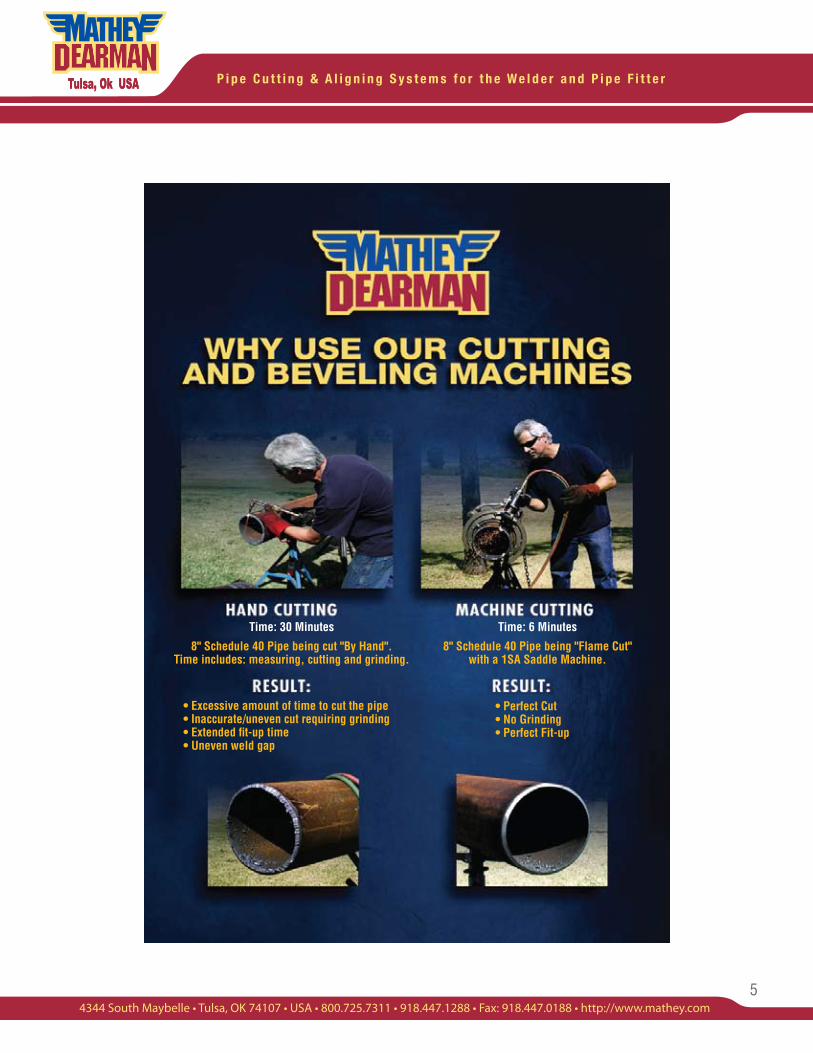
Time: 6 Minutes
8" Schedule 40 Pipe being "Flame Cut" with a 1SA Saddle Machine.
• Perfect Cut • No Grinding • Perfect Fit-up
Time: 30 Minutes
8" Schedule 40 Pipe being cut "By Hand". Time includes: measuring, cutting and grinding.
• Excessive amount of time to cut the pipe • Inaccurate/uneven cut requiring grinding • Extended fit-up time • Uneven weld gap
P i p e C u t t i n g & A l i g n i n g S y s t e m s f o r t h e W e l d e r a n d P i p e F i t t e r
6
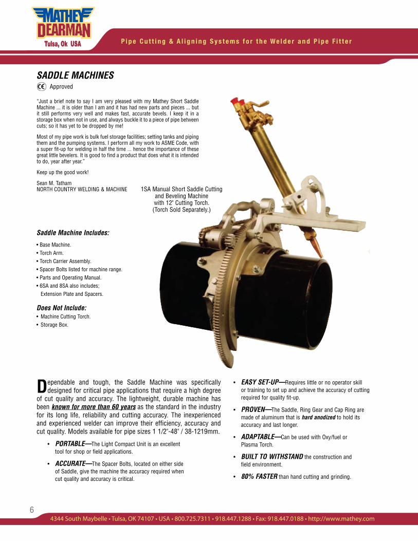
SADDLE MACHINES
Dependable and tough, the Saddle Machine was specifically designed for critical pipe applications that require a high degree
of cut quality and accuracy. The lightweight, durable machine has been known for more than 60 years as the standard in the industry for its long life, reliability and cutting accuracy. The inexperienced and experienced welder can improve their efficiency, accuracy and cut quality. Models available for pipe sizes 1 1/2"-48" / 38-1219mm.
• PORTABLE—The Light Compact Unit is an excellent tool for shop or field applications.
• ACCURATE—The Spacer Bolts, located on either side of Saddle, give the machine the accuracy required when cut quality and accuracy is critical.
• EASY SET-UP—Requires little or no operator skill or training to set up and achieve the accuracy of cutting required for quality fit-up.
• PROVEN—The Saddle, Ring Gear and Cap Ring are made of aluminum that is hard anodized to hold its accuracy and last longer.
• ADAPTABLE—Can be used with Oxy/fuel or Plasma Torch.
• BUILT TO WITHSTAND the construction and field environment.
• 80% FASTER than hand cutting and grinding.
“Just a brief note to say I am very pleased with my Mathey Short Saddle Machine ... it is older than I am and it has had new parts and pieces ... but it still performs very well and makes fast, accurate bevels. I keep it in a storage box when not in use, and always buckle it to a piece of pipe between cuts; so it has yet to be dropped by me!
Most of my pipe work is bulk fuel storage facilities; setting tanks and piping them and the pumping systems. I perform all my work to ASME Code, with a super fit-up for welding in half the time ... hence the importance of these great little bevelers. It is good to find a product that does what it is intended to do, year after year.”
Keep up the good work!
Sean M. Tatham NORTH COUNTRY WELDING & MACHINE
Saddle Machine Includes:
• Base Machine.• Torch Arm. • Torch Carrier Assembly.• Spacer Bolts listed for machine range.• Parts and Operating Manual.• 6SA and 8SA also includes; Extension Plate and Spacers.
Does Not Include:• Machine Cutting Torch. • Storage Box.
1SA Manual Short Saddle Cutting and Beveling Machine with 12" Cutting Torch. (Torch Sold Separately.)
Approved
7
P i p e C u t t i n g & A l i g n i n g S y s t e m s f o r t h e W e l d e r a n d P i p e F i t t e r
4344 South Maybelle • Tulsa, OK 74107 • USA • 800.725.7311 • 918.447.1288 • Fax: 918.447.0188 • http://www.mathey.com
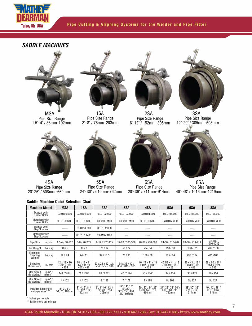
Saddle Machine Quick Selection Chart
2SA 3SA
4SA 5SA 8SA
Pipe Size Range 6"-12" / 152mm-305mm
Pipe Size Range 12"-20" / 305mm-508mm
Pipe Size Range 20"-26" / 508mm-660mm
Pipe Size Range 24"-30" / 610mm-762mm
Pipe Size Range 28"-36" / 711mm-914mm
Pipe Size Range 40"-48" / 1016mm-1219mm
1SAPipe Size Range
1.5"-4" / 38mm-102mmPipe Size Range
3"-8" / 76mm-203mm
MSA
6SA
SADDLE MACHINES
Machine Model MSA 1SA 2SA 3SA 4SA 5SA 6SA 8SAManual with Spacer Bolts 03.0100.000 03.0101.000 03.0102.000 03.0103.000 03.0104.000 03.0105.000 03.0106.000 03.0108.000
Motorized with Spacer Bolts 03.0100.M00 03.0101.M00 03.0102.M00 03.0103.M00 03.0104.M00 03.0105.M00 03.0106.M00 03.0108.M00
Manual with Step Spacers ------ 03.01S1.000 03.01S2.000 ---- ----- ----- ----- -----
Motorized with Step Spacers ------ 03.01S1.M00 03.01S2.M00 ---- ----- ----- ----- -----
Pipe Size in / mm 1.5-4 / 38-102 3-8 / 76-203 6-12 / 152-305 12-20 / 305-508 20-26 / 508-660 24-30 / 610-762 28-36 / 711-914 40-48 / 1016-1219
Net Weight lbs. / kg 10 / 5 16 / 7 26 / 12 50 / 22 75 / 34 110 / 50 180 / 82 287 / 130
EstimatedShipping Weight
lbs. / kg 12 / 5.4 24 / 11 34 / 15.5 73 / 33 150 / 68 185 / 84 295 / 134 415 /188
ShippingDimensions in / mm
12 x 12 x 10 / 305 x 305
x 254
18 x 18 x 11 1/2 / 457 x 457 x 492
23 x 23 x 12 1/2 / 584 x 584 x 318
34 x 32 x 12 / 864 x 813 x 305
40 1/2 x 41 x 19 / 1029 x 1041
x 423
40 1/2 x 41 x 19 / 1029 x 1041
x 423
57 x 43 x 18 / 1488 x 1002
x 483
69 x 60 x 21 / 1753 x 1524
x 533
Max Speed (Motorized)
ipm* / mmm** 141 / 3581 71 / 1803 89 / 2261 47 / 1194 53 / 1346 34 / 864 35 / 889 36 / 914
Min. Speed (Motorized)
ipm* / mmm** 4 / 102 4 / 102 6 / 152 7 / 178 7 / 178 8 / 203 5 / 127 5 / 127
Includes Spacers tocut pipe sizes***
2", 3", 4" / 51, 76, 102mm
3", 4", 6", 8" / 76, 102, 152,
203mm
6", 8", 10", 12" / 152, 203, 254,
305mm
12", 14", 16", 18", 20" /
305, 356, 406, 457, 508mm
20", 22", 24", 26" / 508, 559, 610,
660mm
24", 26", 28", 30" / 610, 660, 711,
762mm
28", 30", 36" / 711, 762,
914mm
40", 42", 48" / 1016, 1067,
1219mm
* Inches per minute** Millimeters per minute
P i p e C u t t i n g & A l i g n i n g S y s t e m s f o r t h e W e l d e r a n d P i p e F i t t e r
8
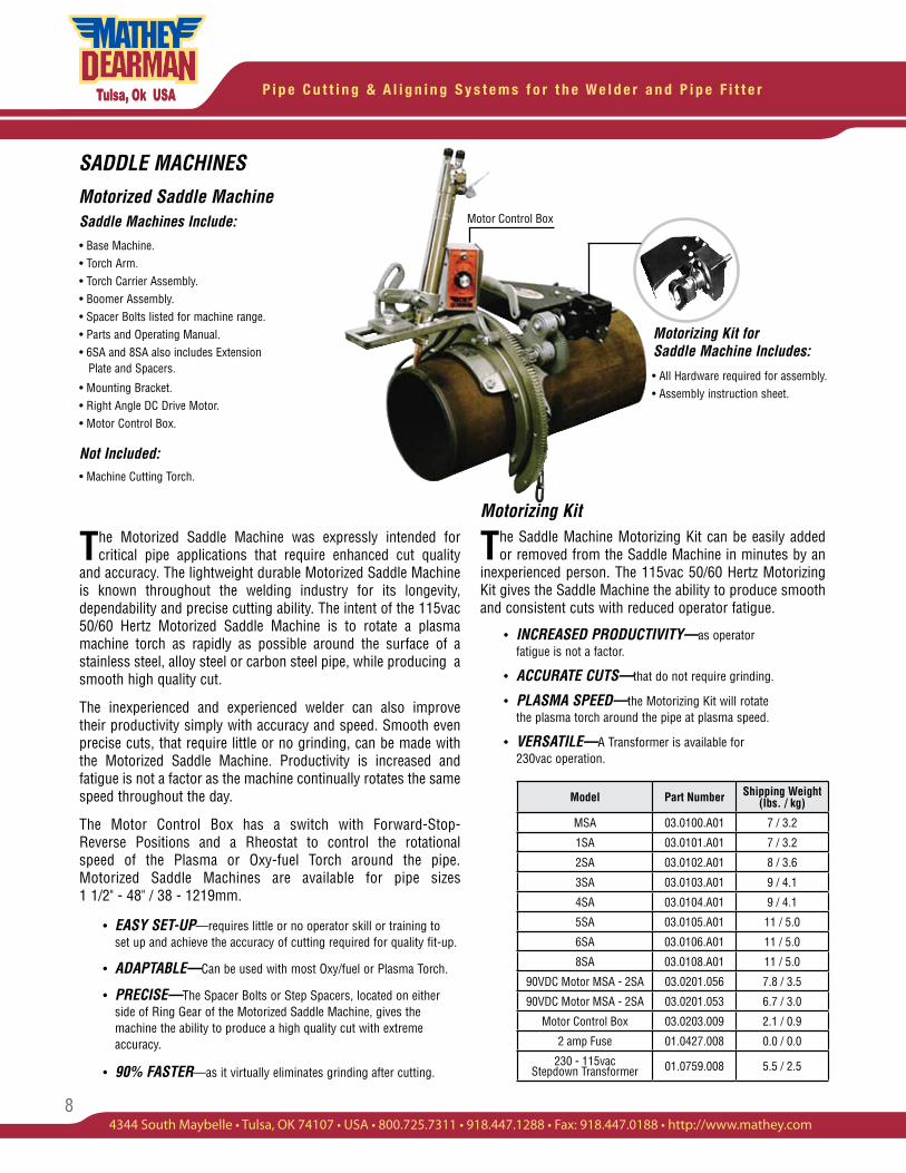
SADDLE MACHINES
Motorized Saddle Machine
The Motorized Saddle Machine was expressly intended for critical pipe applications that require enhanced cut quality
and accuracy. The lightweight durable Motorized Saddle Machine is known throughout the welding industry for its longevity, dependability and precise cutting ability. The intent of the 115vac 50/60 Hertz Motorized Saddle Machine is to rotate a plasma machine torch as rapidly as possible around the surface of a stainless steel, alloy steel or carbon steel pipe, while producing a smooth high quality cut.
The inexperienced and experienced welder can also improve their productivity simply with accuracy and speed. Smooth even precise cuts, that require little or no grinding, can be made with the Motorized Saddle Machine. Productivity is increased and fatigue is not a factor as the machine continually rotates the same speed throughout the day.
The Motor Control Box has a switch with Forward-Stop-Reverse Positions and a Rheostat to control the rotational speed of the Plasma or Oxy-fuel Torch around the pipe. Motorized Saddle Machines are available for pipe sizes 1 1/2" - 48" / 38 - 1219mm.
• EASY SET-UP—requires little or no operator skill or training to set up and achieve the accuracy of cutting required for quality fit-up.
• ADAPTABLE—Can be used with most Oxy/fuel or Plasma Torch.
• PRECISE—The Spacer Bolts or Step Spacers, located on either side of Ring Gear of the Motorized Saddle Machine, gives the machine the ability to produce a high quality cut with extreme accuracy.
• 90% FASTER—as it virtually eliminates grinding after cutting.
Motorizing Kit
The Saddle Machine Motorizing Kit can be easily added or removed from the Saddle Machine in minutes by an
inexperienced person. The 115vac 50/60 Hertz Motorizing Kit gives the Saddle Machine the ability to produce smooth and consistent cuts with reduced operator fatigue.
• INCREASED PRODUCTIVITY—as operator fatigue is not a factor.
• ACCURATE CUTS—that do not require grinding.
• PLASMA SPEED—the Motorizing Kit will rotate the plasma torch around the pipe at plasma speed.
• VERSATILE—A Transformer is available for 230vac operation.
Saddle Machines Include:
• Base Machine.• Torch Arm. • Torch Carrier Assembly.• Boomer Assembly.• Spacer Bolts listed for machine range.• Parts and Operating Manual.• 6SA and 8SA also includes Extension Plate and Spacers.
• Mounting Bracket.• Right Angle DC Drive Motor. • Motor Control Box.
Not Included:• Machine Cutting Torch.
Motorizing Kit for Saddle Machine Includes:
• All Hardware required for assembly.• Assembly instruction sheet.
Motor Control Box
Model Part Number Shipping Weight(lbs. / kg)
MSA 03.0100.A01 7 / 3.2
1SA 03.0101.A01 7 / 3.2
2SA 03.0102.A01 8 / 3.6
3SA 03.0103.A01 9 / 4.1
4SA 03.0104.A01 9 / 4.1
5SA 03.0105.A01 11 / 5.0
6SA 03.0106.A01 11 / 5.0
8SA 03.0108.A01 11 / 5.0
90VDC Motor MSA - 2SA 03.0201.056 7.8 / 3.5
90VDC Motor MSA - 2SA 03.0201.053 6.7 / 3.0
Motor Control Box 03.0203.009 2.1 / 0.9
2 amp Fuse 01.0427.008 0.0 / 0.0
230 - 115vac Stepdown Transformer 01.0759.008 5.5 / 2.5
9
P i p e C u t t i n g & A l i g n i n g S y s t e m s f o r t h e W e l d e r a n d P i p e F i t t e r
4344 South Maybelle • Tulsa, OK 74107 • USA • 800.725.7311 • 918.447.1288 • Fax: 918.447.0188 • http://www.mathey.com
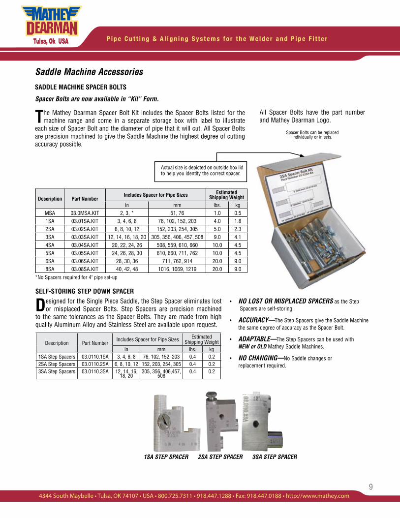
Spacer Bolts are now available in “Kit” Form.
The Mathey Dearman Spacer Bolt Kit includes the Spacer Bolts listed for the machine range and come in a separate storage box with label to illustrate
each size of Spacer Bolt and the diameter of pipe that it will cut. All Spacer Bolts are precision machined to give the Saddle Machine the highest degree of cutting accuracy possible.
Saddle Machine Accessories
SADDLE MACHINE SPACER BOLTS
Actual size is depicted on outside box lid to help you identify the correct spacer.
Description Part NumberIncludes Spacer for Pipe Sizes Estimated
Shipping Weightin mm lbs. kg
MSA 03.0MSA.KIT 2, 3, * 51, 76 1.0 0.51SA 03.01SA.KIT 3, 4, 6, 8 76, 102, 152, 203 4.0 1.82SA 03.02SA.KIT 6, 8, 10, 12 152, 203, 254, 305 5.0 2.33SA 03.03SA.KIT 12, 14, 16, 18, 20 305, 356, 406, 457, 508 9.0 4.14SA 03.04SA.KIT 20, 22, 24, 26 508, 559, 610, 660 10.0 4.55SA 03.05SA.KIT 24, 26, 28, 30 610, 660, 711, 762 10.0 4.56SA 03.06SA.KIT 28, 30, 36 711, 762, 914 20.0 9.08SA 03.08SA.KIT 40, 42, 48 1016, 1069, 1219 20.0 9.0
• NO LOST OR MISPLACED SPACERS as the Step Spacers are self-storing.
• ACCURACY—The Step Spacers give the Saddle Machine the same degree of accuracy as the Spacer Bolt.
• ADAPTABLE—The Step Spacers can be used with NEW or OLD Mathey Saddle Machines.
• NO CHANGING—No Saddle changes or replacement required.
SELF-STORING STEP DOWN SPACER
Designed for the Single Piece Saddle, the Step Spacer eliminates lost or misplaced Spacer Bolts. Step Spacers are precision machined
to the same tolerances as the Spacer Bolts. They are made from high quality Aluminum Alloy and Stainless Steel are available upon request.
Description Part NumberIncludes Spacer for Pipe Sizes Estimated
Shipping Weightin mm lbs. kg
1SA Step Spacers 03.0110.1SA 3, 4, 6, 8 76, 102, 152, 203 0.4 0.22SA Step Spacers 03.0110.2SA 6, 8, 10, 12 152, 203, 254, 305 0.4 0.23SA Step Spacers 03.0110.3SA 12, 14, 16,
18, 20305, 356, 406,457,
5080.4 0.2
*No Spacers required for 4" pipe set-up
All Spacer Bolts have the part number and Mathey Dearman Logo.
Spacer Bolts can be replaced individually or in sets.
1SA STEP SPACER 2SA STEP SPACER 3SA STEP SPACER
P i p e C u t t i n g & A l i g n i n g S y s t e m s f o r t h e W e l d e r a n d P i p e F i t t e r
10
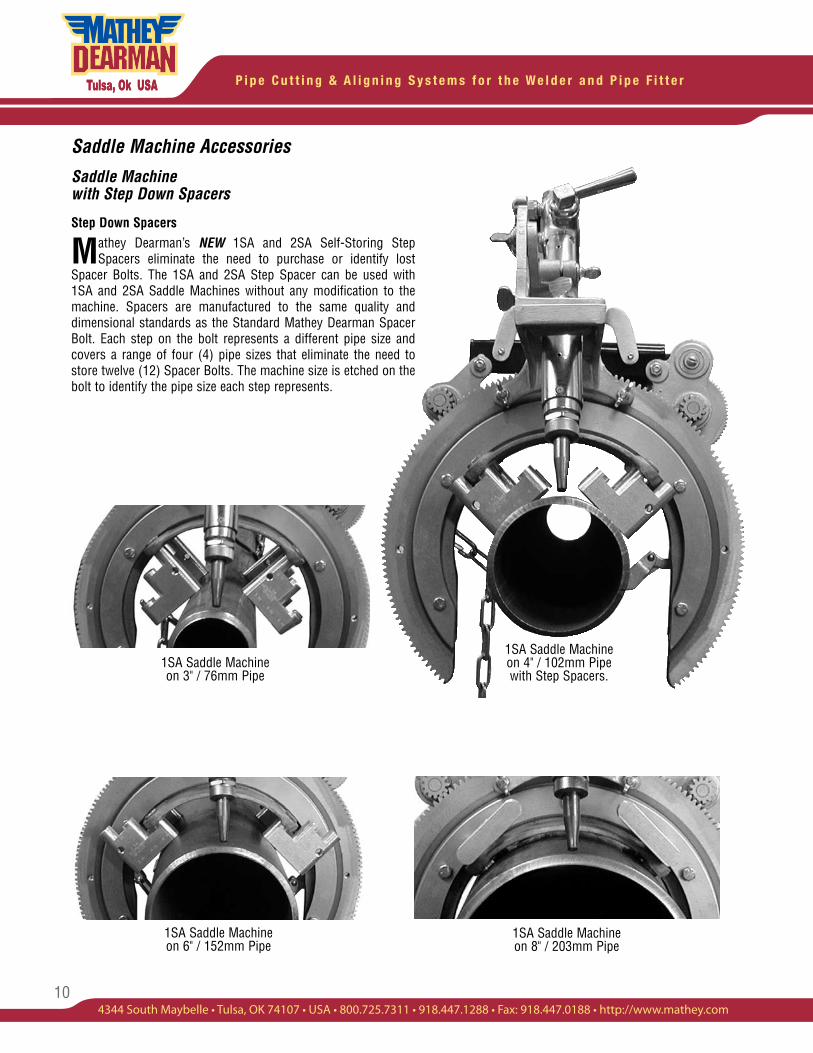
1SA Saddle Machine on 4" / 102mm Pipe with Step Spacers.
1SA Saddle Machine on 3" / 76mm Pipe
1SA Saddle Machine on 8" / 203mm Pipe
Saddle Machine Accessories
Saddle Machine with Step Down Spacers
Step Down Spacers
Mathey Dearman’s NEW 1SA and 2SA Self-Storing Step Spacers eliminate the need to purchase or identify lost
Spacer Bolts. The 1SA and 2SA Step Spacer can be used with 1SA and 2SA Saddle Machines without any modification to the machine. Spacers are manufactured to the same quality and dimensional standards as the Standard Mathey Dearman Spacer Bolt. Each step on the bolt represents a different pipe size and covers a range of four (4) pipe sizes that eliminate the need to store twelve (12) Spacer Bolts. The machine size is etched on the bolt to identify the pipe size each step represents.
1SA Saddle Machine on 6" / 152mm Pipe
11
P i p e C u t t i n g & A l i g n i n g S y s t e m s f o r t h e W e l d e r a n d P i p e F i t t e r
4344 South Maybelle • Tulsa, OK 74107 • USA • 800.725.7311 • 918.447.1288 • Fax: 918.447.0188 • http://www.mathey.com
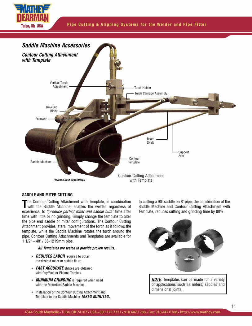
Vertical Torch Adjustment
Traveling Block
Beam Shaft
Support Arm
Saddle MachineContour
Template
Follower
Torch Holder
SADDLE AND MITER CUTTING
The Contour Cutting Attachment with Template, in combination with the Saddle Machine, enables the welder, regardless of
experience, to “produce perfect miter and saddle cuts” time after time with little or no grinding. Simply change the template to alter the pipe end saddle or miter configurations. The Contour Cutting Attachment provides lateral movement of the torch as it follows the template, while the Saddle Machine rotates the torch around the pipe. Contour Cutting Attachments and Templates are available for 1 1/2" – 48" / 38-1219mm pipe.
All Templates are tested to provide proven results.
• REDUCES LABOR required to obtain the desired miter or saddle fit-up.
• FAST ACCURATE shapes are obtained with Oxy/Fuel or Plasma Torches.
• MINIMUM GRINDING is required when used with the Motorized Saddle Machine.
• Installation of the Contour Cutting Attachment and Template to the Saddle Machine TAKES MINUTES.
NOTE: Templates can be made for a variety of applications such as miters, saddles and dimensional joints.
Saddle Machine Accessories
Contour Cutting Attachment with Template
Contour Cutting Attachment with Template(Torches Sold Separately.)
In cutting a 90º saddle on 8" pipe, the combination of the Saddle Machine and Contour Cutting Attachment with Template, reduces cutting and grinding time by 80%.
Torch Carriage Assembly
P i p e C u t t i n g & A l i g n i n g S y s t e m s f o r t h e W e l d e r a n d P i p e F i t t e r
12
Saddle Machine Accessories
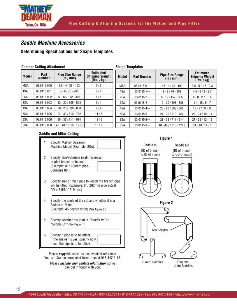
Determining Specifications for Shape Templates
Diagonal Joint Saddles
T-Joint Saddles
Figure 2
Miter Angles
Saddle In
(ID of branch to ID of main)
Saddle On
(ID of branch to OD of main)
Figure 1
Shape TemplatesContour Cutting Attachment
1. Specify Mathey Dearman Machine Model (Example: 2SA).
2. Specify size/schedule (wall thickness) of pipe branch to be cut. (Example: 8" / 203mm pipe- Schedule 80.)
3. Specify size of main pipe to which the branch pipe will be fitted. (Example: 8" / 203mm pipe actual OD = 8 5/8" / 219mm.)
4. Specify the angle of the cut and whether it is a Saddle or Miter. (Example: 45 degree miter) (See Figure 2.)
5. Specify whether the joint is “Saddle In” or “Saddle On” (See Figure 1.)
6. Specify if pipe is to be offset. If the answer is yes, specify how much the pipe is to be offset.
Please copy this sheet as a convenient reference. You can fax the completed form to us at 918 447-0188.
Please include your contact information so we can get in touch with you.
Saddle and Miter Cutting
Model Part Number
Pipe Size Range (in / mm)
Estimated Shipping Weight
(lbs. / kg)
MSA 03.0116.000 1.5 - 4 / 38 - 102 7 / 3
1SA 03.0116.001 3 - 8 / 76 - 203 8 / 4
2SA 03.0116.002 6 - 12 / 152 - 305 8 / 4
3SA 03.0116.003 12 - 20 / 305 - 508 9 / 4
4SA 03.0116.004 20 - 26 / 508 - 660 9 / 4
5SA 03.0116.005 24 - 30 / 610 - 762 11 / 5
6SA 03.0116.006 28 - 36 / 711 - 914 13 / 6
8SA 03.0116.008 40 - 48 / 1016 - 1219 16 / 7
Model Part Number Pipe Size Range(in / mm)
Estimated Shipping Weight
(lbs. / kg)
MSA 03.0115.M--- 1.5 - 4 / 38 - 102 3.5 - 5 / 1.6 - 2.3
1SA 03.0115.1--- 3 - 8 / 76 - 203 4.5 - 6 / 2 - 2.7
2SA 03.0115.2--- 6 - 12 / 152 - 305 6 - 8 / 2.7 - 3.6
3SA 03.0115-3--- 12 - 20 / 305 - 508 11 - 15 / 5 - 7
4SA 03.0115.4--- 20 - 26 / 508 - 660 18 - 27 / 8 - 12
5SA 03.0115.5--- 24 - 30 / 610 - 762 22 - 31 / 10 - 14
6SA 03.0115.6--- 28 - 36 / 711 - 914 27 - 35 / 12 - 16
8SA 03.0115.8--- 40 - 48 / 1016 - 1219 31 - 40 / 14 - 1
13
P i p e C u t t i n g & A l i g n i n g S y s t e m s f o r t h e W e l d e r a n d P i p e F i t t e r
4344 South Maybelle • Tulsa, OK 74107 • USA • 800.725.7311 • 918.447.1288 • Fax: 918.447.0188 • http://www.mathey.com
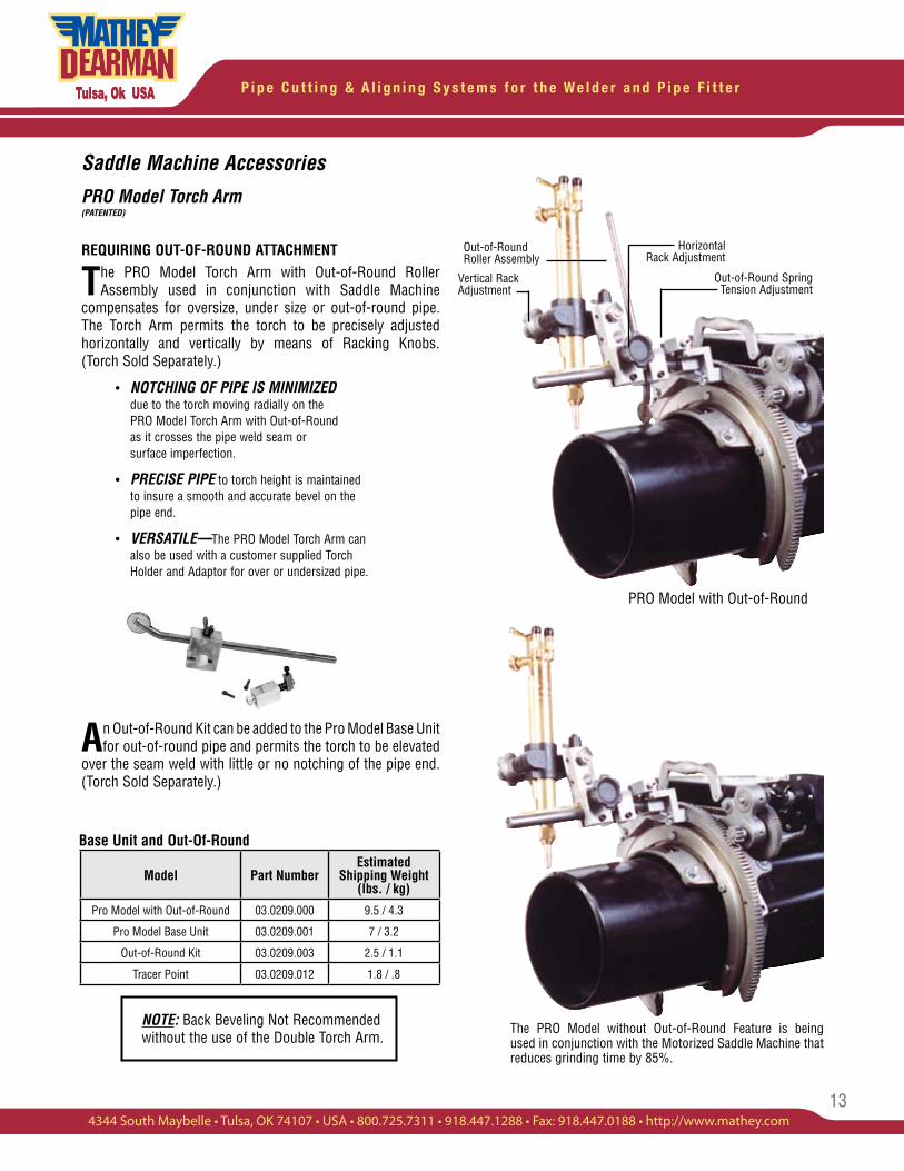
Horizontal Rack Adjustment
Vertical Rack Adjustment
Out-of-Round Spring Tension Adjustment
Out-of-Round Roller Assembly
The PRO Model without Out-of-Round Feature is being used in conjunction with the Motorized Saddle Machine that reduces grinding time by 85%.
Base Unit and Out-Of-Round
PRO Model with Out-of-Round
NOTE: Back Beveling Not Recommended without the use of the Double Torch Arm.
Model Part NumberEstimated
Shipping Weight (lbs. / kg)
Pro Model with Out-of-Round 03.0209.000 9.5 / 4.3
Pro Model Base Unit 03.0209.001 7 / 3.2
Out-of-Round Kit 03.0209.003 2.5 / 1.1
Tracer Point 03.0209.012 1.8 / .8
Saddle Machine Accessories
PRO Model Torch Arm(PATENTED)
REQUIRING OUT-OF-ROUND ATTACHMENT
The PRO Model Torch Arm with Out-of-Round Roller Assembly used in conjunction with Saddle Machine
compensates for oversize, under size or out-of-round pipe. The Torch Arm permits the torch to be precisely adjusted horizontally and vertically by means of Racking Knobs. (Torch Sold Separately.)
• NOTCHING OF PIPE IS MINIMIZED due to the torch moving radially on the PRO Model Torch Arm with Out-of-Round as it crosses the pipe weld seam or surface imperfection.
• PRECISE PIPE to torch height is maintained to insure a smooth and accurate bevel on the pipe end.
• VERSATILE—The PRO Model Torch Arm can also be used with a customer supplied Torch Holder and Adaptor for over or undersized pipe.
An Out-of-Round Kit can be added to the Pro Model Base Unit for out-of-round pipe and permits the torch to be elevated
over the seam weld with little or no notching of the pipe end. (Torch Sold Separately.)
P i p e C u t t i n g & A l i g n i n g S y s t e m s f o r t h e W e l d e r a n d P i p e F i t t e r
14
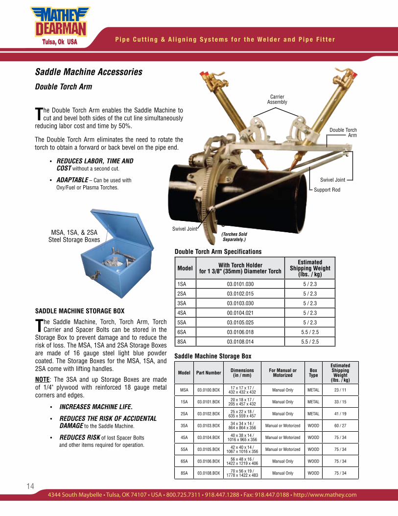
Saddle Machine Accessories
Double Torch ArmCarrier
Assembly
Swivel Joint
Support Rod
The Double Torch Arm enables the Saddle Machine to cut and bevel both sides of the cut line simultaneously
reducing labor cost and time by 50%.
The Double Torch Arm eliminates the need to rotate the torch to obtain a forward or back bevel on the pipe end.
• REDUCES LABOR, TIME AND COST without a second cut.
• ADAPTABLE – Can be used with Oxy/Fuel or Plasma Torches.
(Torches Sold Separately.)
Double Torch Arm Specifications
Double Torch Arm
Saddle Machine Storage Box
MSA, 1SA, & 2SA Steel Storage Boxes
Model Part Number Dimensions(in / mm)
For Manual or Motorized
Box Type
EstimatedShipping Weight
(lbs. / kg)
MSA 03.0100.BOX 17 x 17 x 17 / 432 x 432 x 432 Manual Only METAL 23 / 11
1SA 03.0101.BOX 20 x 18 x 17 / 205 x 457 x 432 Manual Only METAL 33 / 15
2SA 03.0102.BOX 25 x 22 x 18 / 635 x 559 x 457 Manual Only METAL 41 / 19
3SA 03.0103.BOX 34 x 34 x 14 / 864 x 864 x 356 Manual or Motorized WOOD 60 / 27
4SA 03.0104.BOX 40 x 38 x 14 / 1016 x 965 x 356 Manual or Motorized WOOD 75 / 34
5SA 03.0105.BOX 42 x 40 x 14 / 1067 x 1016 x 356 Manual or Motorized WOOD 75 / 34
6SA 03.0106.BOX 56 x 48 x 16 / 1422 x 1219 x 406 Manual Only WOOD 75 / 34
8SA 03.0108.BOX 70 x 56 x 19 / 1778 x 1422 x 483 Manual Only WOOD 75 / 34
Model With Torch Holder for 1 3/8" (35mm) Diameter Torch
Estimated Shipping Weight
(lbs. / kg)
1SA 03.0101.030 5 / 2.3
2SA 03.0102.015 5 / 2.3
3SA 03.0103.030 5 / 2.3
4SA 00.0104.021 5 / 2.3
5SA 03.0105.025 5 / 2.3
6SA 03.0106.018 5.5 / 2.5
8SA 03.0108.014 5.5 / 2.5
Swivel Joint
SADDLE MACHINE STORAGE BOX
The Saddle Machine, Torch, Torch Arm, Torch Carrier and Spacer Bolts can be stored in the
Storage Box to prevent damage and to reduce the risk of loss. The MSA, 1SA and 2SA Storage Boxes are made of 16 gauge steel light blue powder coated. The Storage Boxes for the MSA, 1SA, and 2SA come with lifting handles.
NOTE: The 3SA and up Storage Boxes are made of 1/4" plywood with reinforced 18 gauge metal corners and edges.
• INCREASES MACHINE LIFE.
• REDUCES THE RISK OF ACCIDENTAL DAMAGE to the Saddle Machine.
• REDUCES RISK of lost Spacer Bolts and other items required for operation.
15
P i p e C u t t i n g & A l i g n i n g S y s t e m s f o r t h e W e l d e r a n d P i p e F i t t e r
4344 South Maybelle • Tulsa, OK 74107 • USA • 800.725.7311 • 918.447.1288 • Fax: 918.447.0188 • http://www.mathey.com
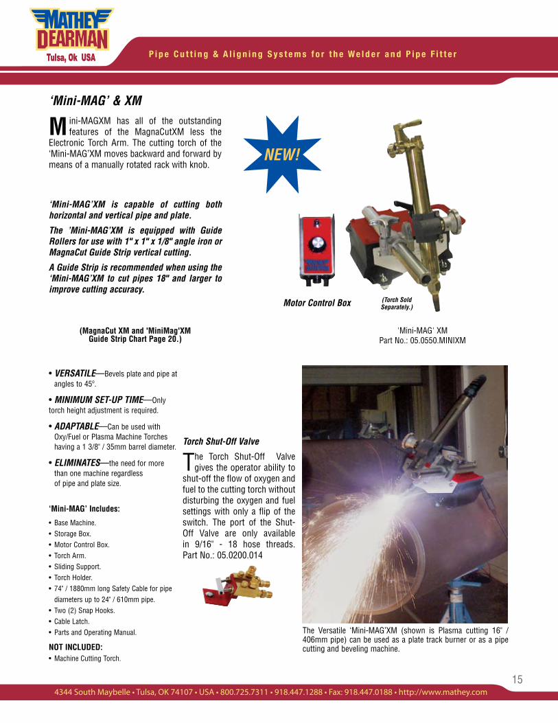
'Mini-MAG' XM Part No.: 05.0550.MINIXM
The Versatile ‘Mini-MAG’XM (shown is Plasma cutting 16" / 406mm pipe) can be used as a plate track burner or as a pipe cutting and beveling machine.
✸NEW!
(Torch Sold Separately.)
‘Mini-MAG’ & XM
M ini-MAGXM has all of the outstanding features of the MagnaCutXM less the
Electronic Torch Arm. The cutting torch of the ‘Mini-MAG’XM moves backward and forward by means of a manually rotated rack with knob.
‘Mini-MAG’XM is capable of cutting both horizontal and vertical pipe and plate.
The ’Mini-MAG’XM is equipped with Guide Rollers for use with 1" x 1" x 1/8" angle iron or MagnaCut Guide Strip vertical cutting.
A Guide Strip is recommended when using the ‘Mini-MAG’XM to cut pipes 18" and larger to improve cutting accuracy.
(MagnaCut XM and 'MiniMag'XM Guide Strip Chart Page 20.)
• VERSATILE—Bevels plate and pipe at angles to 45º.
• MINIMUM SET-UP TIME —Only torch height adjustment is required.
• ADAPTABLE—Can be used with Oxy/Fuel or Plasma Machine Torches having a 1 3/8" / 35mm barrel diameter.
• ELIMINATES—the need for more than one machine regardless of pipe and plate size.
‘Mini-MAG’ Includes:
• Base Machine.• Storage Box.• Motor Control Box.• Torch Arm.• Sliding Support.• Torch Holder.• 74" / 1880mm long Safety Cable for pipe diameters up to 24" / 610mm pipe.• Two (2) Snap Hooks.• Cable Latch.• Parts and Operating Manual.
NOT INCLUDED:• Machine Cutting Torch.
Torch Shut-Off Valve
The Torch Shut-Off Valve gives the operator ability to
shut-off the flow of oxygen and fuel to the cutting torch without disturbing the oxygen and fuel settings with only a flip of the switch. The port of the Shut-Off Valve are only available in 9/16" - 18 hose threads. Part No.: 05.0200.014
Motor Control Box
P i p e C u t t i n g & A l i g n i n g S y s t e m s f o r t h e W e l d e r a n d P i p e F i t t e r
16
‘Mini-MAG’XM
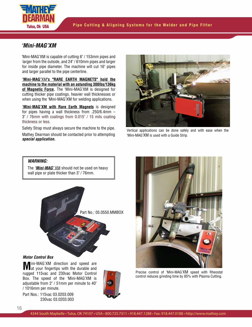
Mini-MAG’XM is capable of cutting 6" / 153mm pipes and larger from the outside, and 24" / 610mm pipes and larger for inside pipe diameter. The machine will cut 16" pipes and larger parallel to the pipe centerline.
‘Mini-MAG’XM's "RARE EARTH MAGNETS" hold the machine to the material with an astunding 300lbs/136kg of Magnetic Force. The ‘Mini-MAG’XM is designed for cutting thicker pipe coatings, heavier wall thicknesses or when using the ‘Mini-MAG’XM for welding applications.
‘Mini-MAG’XM with Rare Earth Magnets is designed for pipes having a wall thickness from .250/6.4mm – 3" / 76mm with coatings from 0.015" / 15 mils coating thickness or less.Safety Strap must always secure the machine to the pipe. Mathey Dearman should be contacted prior to attempting special application.
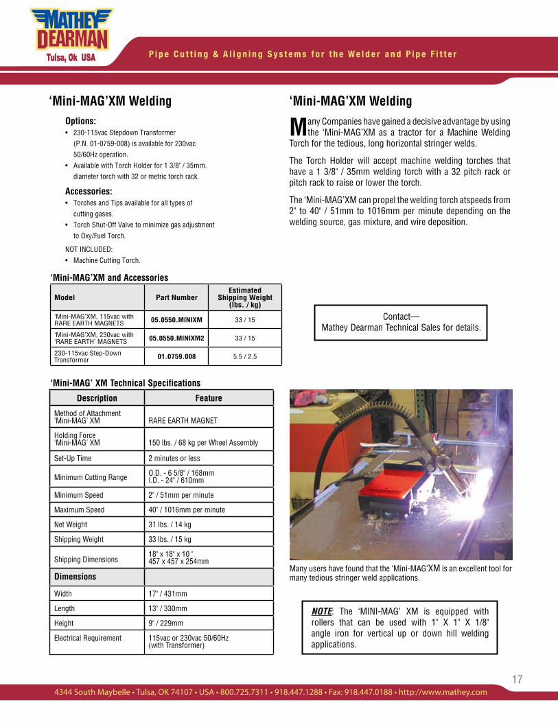
Motor Control Box
Mini-MAG'XM direction and speed are at your fingertips with the durable and
rugged 115vac and 230vac Motor Control Box. The speed of the ‘Mini-MAG’XM is adjustable from 2" / 51mm per minute to 40" / 1016mm per minute.Part Nos.: 115vac 03.0203.009 230vac 03.0203.003
Vertical applications can be done safely and with ease when the ‘Mini-MAG’XM is used with a Guide Strip.
WARNING:The ‘Mini-MAG’ XM should not be used on heavy wall pipe or plate thicker than 3" / 76mm.
Precise control of ‘Mini-MAG’XM speed with Rheostat control reduces grinding time by 85% with Plasma Cutting.
Part No.: 05.0550.MMBOX
‘
17
P i p e C u t t i n g & A l i g n i n g S y s t e m s f o r t h e W e l d e r a n d P i p e F i t t e r
4344 South Maybelle • Tulsa, OK 74107 • USA • 800.725.7311 • 918.447.1288 • Fax: 918.447.0188 • http://www.mathey.com
‘Mini-MAG’XM WeldingOptions:• 230-115vac Stepdown Transformer (P.N. 01-0759-008) is available for 230vac 50/60Hz operation.• Available with Torch Holder for 1 3/8" / 35mm. diameter torch with 32 or metric torch rack.
Accessories:• Torches and Tips available for all types of cutting gases.• Torch Shut-Off Valve to minimize gas adjustment to Oxy/Fuel Torch.
NOT INCLUDED:• Machine Cutting Torch.
Description Feature
Method of Attachment ‘Mini-MAG’ XM RARE EARTH MAGNET
Holding Force‘Mini-MAG’ XM 150 lbs. / 68 kg per Wheel Assembly
Set-Up Time 2 minutes or less
Minimum Cutting Range O.D. - 6 5/8" / 168mmI.D. - 24" / 610mm
Minimum Speed 2" / 51mm per minute
Maximum Speed 40" / 1016mm per minute
Net Weight 31 lbs. / 14 kg
Shipping Weight 33 lbs. / 15 kg
Shipping Dimensions18" x 18" x 10 "457 x 457 x 254mm
Dimensions
Width 17" / 431mm
Length 13" / 330mm
Height 9" / 229mm
Electrical Requirement 115vac or 230vac 50/60Hz (with Transformer)
‘Mini-MAG’XM Welding
Many Companies have gained a decisive advantage by using the ‘Mini-MAG’XM as a tractor for a Machine Welding
Torch for the tedious, long horizontal stringer welds.
The Torch Holder will accept machine welding torches that have a 1 3/8" / 35mm welding torch with a 32 pitch rack or pitch rack to raise or lower the torch.
The ‘Mini-MAG’XM can propel the welding torch atspeeds from 2" to 40" / 51mm to 1016mm per minute depending on the welding source, gas mixture, and wire deposition.
Many users have found that the ‘Mini-MAG’XM is an excellent tool for many tedious stringer weld applications.
Contact— Mathey Dearman Technical Sales for details.
NOTE: The ‘MINI-MAG’ XM is equipped with rollers that can be used with 1" X 1" X 1/8" angle iron for vertical up or down hill welding applications.
‘Mini-MAG’XM and Accessories
Model Part NumberEstimated
Shipping Weight (lbs. / kg)
‘Mini-MAG’XM, 115vac with RARE EARTH MAGNETS 05.0550.MINIXM 33 / 15
‘Mini-MAG’XM, 230vac with ‘RARE EARTH’ MAGNETS 05.0550.MINIXM2 33 / 15
230-115vac Step-Down Transformer 01.0759.008 5.5 / 2.5
‘Mini-MAG’ XM Technical Specifications
P i p e C u t t i n g & A l i g n i n g S y s t e m s f o r t h e W e l d e r a n d P i p e F i t t e r
18
The MagnaCut XM Pipe and Plate Cutting Machine cuts 6" / 153mm pipe thickness of .250" / 6.4mm to 3" / 76mm
using Plasma and Oxy/Acetylene Cutting Torches. Plate can also be cut cleanly and quickly using a piece of 1"x1"x1/8" / 25x25x3mm angle iron as a guide strip for accuracy.
MagnaCut’s awesome magnetic strength is due to “RARE EARTH MAGNETS” that hold the machine on larger and thicker coated pipe with 300 pounds of magnetic force.
The MagnaCut XM, with Remote Controlled Torch Arm combined with a Machine Oxy/Fuel or Plasma Cutting Torch is an excellent choice when cutting a variety of sizes and thickness of pipe and plate. The magnetic cutting and beveling machine is ideal for hard to reach locations, such as overhead pipes and vertical walls, because it can be remotely operated from the Motor Control Box.
This is the machine for you—whether you are a contractor, fabricator, or maintenance welder cutting coated pipe or plate. No need to worry about out-of-square cuts due to variance in pipe diameter or due to pipe coating thickness up to 0.015 / 15mls – the pipe to torch height remains constant.
MagnaCut XM
• MINIMUM SET-UP TIME involves only adjustment of cutting torch to material height.
• VERSATILITY—Cuts Pipe, Plate, vertical walls and overheads.
• MAXIMUM SPEED—Speed and direction of machine, as well as Torch Arm Speed and Direction, are remotely controlled from the Industrial Motor Control Box that minimizes the risk of injury to the operator.
• AWESOME HOLDING POWER—'Rare Earth Magnets' of the MagnaCut XM will adhere to any magnetic receptive pipe or plate with coating up to .015" / .4mm (15mils).
• 80% FASTER than hand cutting and grinding.
Options: • A 230-115vac Step-down Transformer (P.N. 01-0759-008) is available for 230vac 50/60Hz operation. • Available with Torch Holder for 1 3/8" / 35mm diameter torch with 32 Pitch or metric torch rack.
Accessories: • 12' / 3.7mt Extension Cord for pipe diameters larger than 36" / 914mm.
• Plasma Torch Adapter for plasma cutting.
• Torches and Tips available for all types of cutting gases.
• Torch Shut-Off Valve to minimize adjustment of cutting torch.
(PATENTED.)
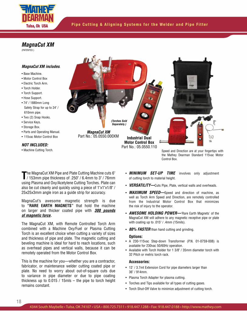
MagnaCut XM includes:
• Base Machine.• Motor Control Box• Electric Torch Arm.• Torch Holder.• Torch Support.• Hose Support.• 74" / 1880mm Long Safety Strap for up to 24" / 610mm pipe.• Two (2) Snap Hooks. • Service Keys.• Storage Box.• Parts and Operating Manual.• 115vac Motor Control Box
NOT INCLUDED:• Machine Cutting Torch.
(Torches Sold Separately.)
Industrial Dual Motor Control Box
Part No.: 05.0550.110Speed and Direction are at your fingertips with the Mathey Dearman Standard 115vac Motor Control Box.
MagnaCut XM Part No.: 05.0550.000XM
19
P i p e C u t t i n g & A l i g n i n g S y s t e m s f o r t h e W e l d e r a n d P i p e F i t t e r
4344 South Maybelle • Tulsa, OK 74107 • USA • 800.725.7311 • 918.447.1288 • Fax: 918.447.0188 • http://www.mathey.com
MagnaCut XM and Accessories
MagnaCut XM(PATENTED.)
Model Part NumberEstimated
Shipping Weight (lbs. / kg)
MagnaCut XM, 115vac 50/60 Hz 05.0550.000XM 60 / 27
230-115vac Step-Down Transformer 01.0759.008 5.5 / 2.5
Description MagnaCut XM
Method of Attachment to Pipe or Plate Rare Earth Magnets
Magnetic Pull per Wheel Assembly 150lbs. / 68kg
Polyurethane, Carbon Zinc or Epoxy Coatings
Up to 15mils or .015" / .4mm thick.
Set Up Time 2 Minutes or less
Cutting Range (Pipe O.D.) 6 5/8" / 168mm and up
Cutting Range (Pipe I.D.) 24" / 610mm and up
Vertical Cutting Capability Pipe or Plate
Horizontal Cutting Capability Pipe or Plate
Diagonal Cutting Capability Plate only
Miter or Saddle Cutting Capability on Pipe
Shallow Miters or Saddles only
Minimum Speed 2" / 51mm per Minute
Maximum Speed 40" / 1016mm per Minute
Net Weight 37 lbs. / 16.7 kg
Estimate Shipping Weight 60lbs. / 27 kg
Shipping Dimensions20" x 9" x 25" /
508 x 229 x 635
Machine Dimensions
Width (Torch Arm Extended) 17” / 432mm
Length 14" / 356mm
Height 5 1/4" / 133mm
Electrical Requirement 115vac or 230vac 50/60Hz (With Transformer)
* A Guide Strip made of 1 3/8" Angle Iron is available for MagnaCut to cut pipe 18" and larger.
MagnaCut XM Technical Specifications
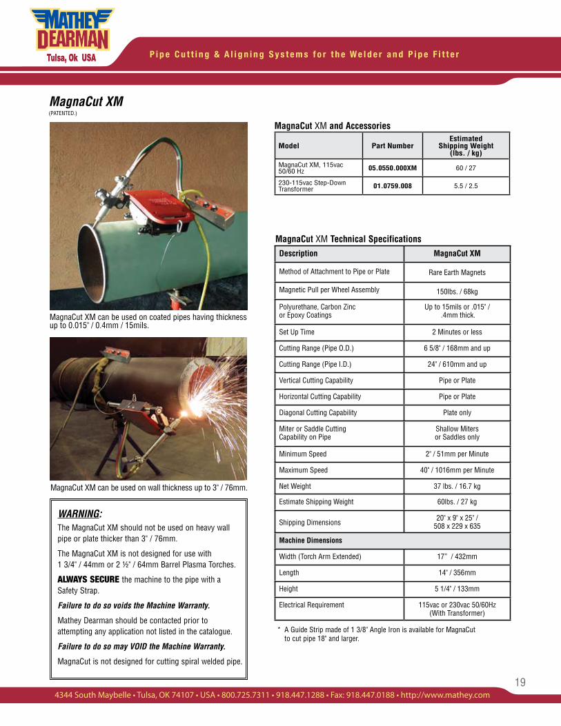
MagnaCut XM can be used on coated pipes having thickness up to 0.015" / 0.4mm / 15mils.
MagnaCut XM can be used on wall thickness up to 3" / 76mm.
WARNING:The MagnaCut XM should not be used on heavy wall pipe or plate thicker than 3" / 76mm.
The MagnaCut XM is not designed for use with 1 3/4" / 44mm or 2 ½" / 64mm Barrel Plasma Torches.
ALWAYS SECURE the machine to the pipe with a Safety Strap.
Failure to do so voids the Machine Warranty.
Mathey Dearman should be contacted prior to attempting any application not listed in the catalogue.
Failure to do so may VOID the Machine Warranty.
MagnaCut is not designed for cutting spiral welded pipe.
P i p e C u t t i n g & A l i g n i n g S y s t e m s f o r t h e W e l d e r a n d P i p e F i t t e r
20
MagnaCut XM(PATENTED.)
MagnaCut XM Spare Parts and Accessories
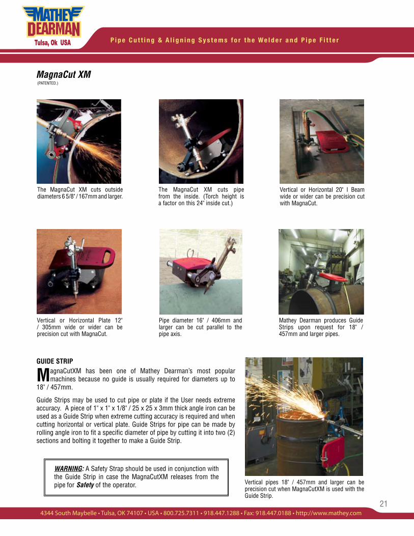
Designed to adapt to Plasma Company’s Supplied Torch Holder. (Torch and Torch Rack Sold Separately.)
Part No.: 05.0510.302
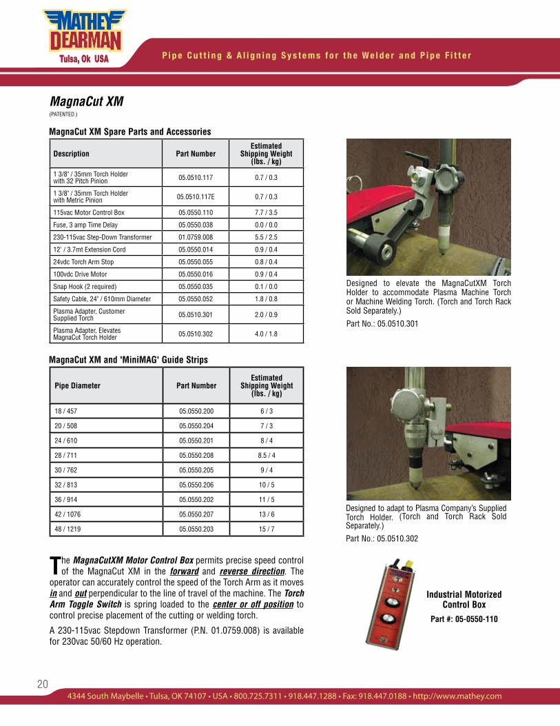
Designed to elevate the MagnaCutXM Torch Holder to accommodate Plasma Machine Torch or Machine Welding Torch. (Torch and Torch Rack Sold Separately.)
Part No.: 05.0510.301
Description Part NumberEstimated
Shipping Weight (lbs. / kg)
1 3/8" / 35mm Torch Holder with 32 Pitch Pinion 05.0510.117 0.7 / 0.3
1 3/8" / 35mm Torch Holder with Metric Pinion 05.0510.117E 0.7 / 0.3
115vac Motor Control Box 05.0550.110 7.7 / 3.5
Fuse, 3 amp Time Delay 05.0550.038 0.0 / 0.0
230-115vac Step-Down Transformer 01.0759.008 5.5 / 2.5
12' / 3.7mt Extension Cord 05.0550.014 0.9 / 0.4
24vdc Torch Arm Stop 05.0550.055 0.8 / 0.4
100vdc Drive Motor 05.0550.016 0.9 / 0.4
Snap Hook (2 required) 05.0550.035 0.1 / 0.0
Safety Cable, 24" / 610mm Diameter 05.0550.052 1.8 / 0.8
Plasma Adapter, Customer Supplied Torch 05.0510.301 2.0 / 0.9
Plasma Adapter, Elevates MagnaCut Torch Holder 05.0510.302 4.0 / 1.8
MagnaCut XM and 'MiniMAG' Guide Strips
Pipe Diameter Part NumberEstimated
Shipping Weight (lbs. / kg)
18 / 457 05.0550.200 6 / 3
20 / 508 05.0550.204 7 / 3
24 / 610 05.0550.201 8 / 4
28 / 711 05.0550.208 8.5 / 4
30 / 762 05.0550.205 9 / 4
32 / 813 05.0550.206 10 / 5
36 / 914 05.0550.202 11 / 5
42 / 1076 05.0550.207 13 / 6
48 / 1219 05.0550.203 15 / 7
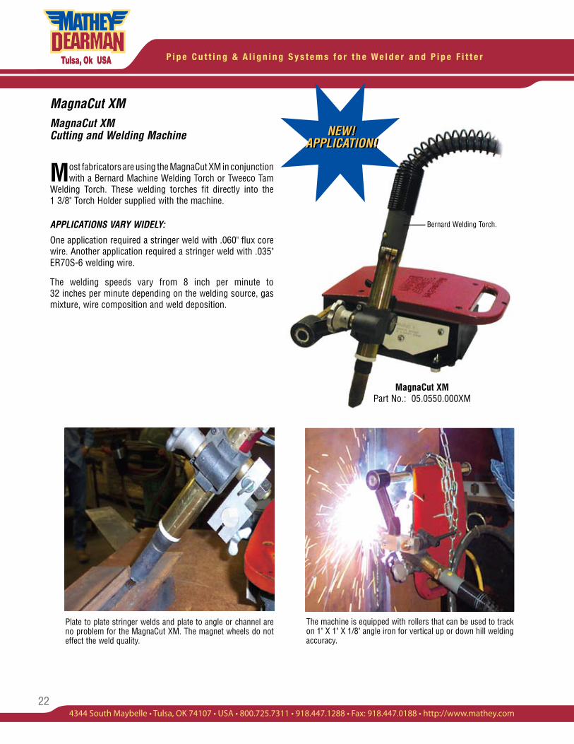
Industrial Motorized Control Box
Part #: 05-0550-110
The MagnaCutXM Motor Control Box permits precise speed control of the MagnaCut XM in the forward and reverse direction. The
operator can accurately control the speed of the Torch Arm as it moves in and out perpendicular to the line of travel of the machine. The Torch Arm Toggle Switch is spring loaded to the center or off position to control precise placement of the cutting or welding torch.
A 230-115vac Stepdown Transformer (P.N. 01.0759.008) is available for 230vac 50/60 Hz operation.
21
P i p e C u t t i n g & A l i g n i n g S y s t e m s f o r t h e W e l d e r a n d P i p e F i t t e r
4344 South Maybelle • Tulsa, OK 74107 • USA • 800.725.7311 • 918.447.1288 • Fax: 918.447.0188 • http://www.mathey.com
MagnaCut XM(PATENTED.)
GUIDE STRIP
MagnaCutXM has been one of Mathey Dearman’s most popular machines because no guide is usually required for diameters up to
18" / 457mm.
Guide Strips may be used to cut pipe or plate if the User needs extreme accuracy. A piece of 1" x 1" x 1/8" / 25 x 25 x 3mm thick angle iron can be used as a Guide Strip when extreme cutting accuracy is required and when cutting horizontal or vertical plate. Guide Strips for pipe can be made by rolling angle iron to fit a specific diameter of pipe by cutting it into two (2) sections and bolting it together to make a Guide Strip.
The MagnaCut XM cuts pipe from the inside. (Torch height is a factor on this 24" inside cut.)
The MagnaCut XM cuts outside diameters 6 5/8" / 167mm and larger.
Vertical or Horizontal 20" I Beam wide or wider can be precision cut with MagnaCut.
Vertical or Horizontal Plate 12" / 305mm wide or wider can be precision cut with MagnaCut.
Pipe diameter 16" / 406mm and larger can be cut parallel to the pipe axis.
Mathey Dearman produces Guide Strips upon request for 18" / 457mm and larger pipes.
Vertical pipes 18" / 457mm and larger can be precision cut when MagnaCutXM is used with the Guide Strip.
WARNING: A Safety Strap should be used in conjunction with the Guide Strip in case the MagnaCutXM releases from the pipe for Safety of the operator.
P i p e C u t t i n g & A l i g n i n g S y s t e m s f o r t h e W e l d e r a n d P i p e F i t t e r
22
MagnaCut XMMagnaCut XM Cutting and Welding Machine
Plate to plate stringer welds and plate to angle or channel are no problem for the MagnaCut XM. The magnet wheels do not effect the weld quality.
The machine is equipped with rollers that can be used to track on 1" X 1" X 1/8" angle iron for vertical up or down hill welding accuracy.
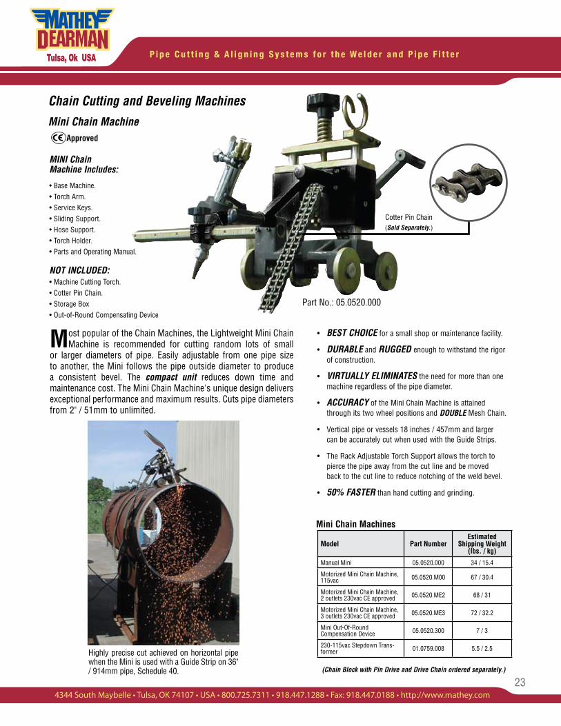
Most fabricators are using the MagnaCut XM in conjunction with a Bernard Machine Welding Torch or Tweeco Tam
Welding Torch. These welding torches fit directly into the 1 3/8" Torch Holder supplied with the machine.
APPLICATIONS VARY WIDELY:
One application required a stringer weld with .060" flux core wire. Another application required a stringer weld with .035" ER70S-6 welding wire.
The welding speeds vary from 8 inch per minute to 32 inches per minute depending on the welding source, gas mixture, wire composition and weld deposition.
✸NEW!APPLICATION!
NEW!APPLICATION!
MagnaCut XM Part No.: 05.0550.000XM
Bernard Welding Torch.
23
P i p e C u t t i n g & A l i g n i n g S y s t e m s f o r t h e W e l d e r a n d P i p e F i t t e r
4344 South Maybelle • Tulsa, OK 74107 • USA • 800.725.7311 • 918.447.1288 • Fax: 918.447.0188 • http://www.mathey.com
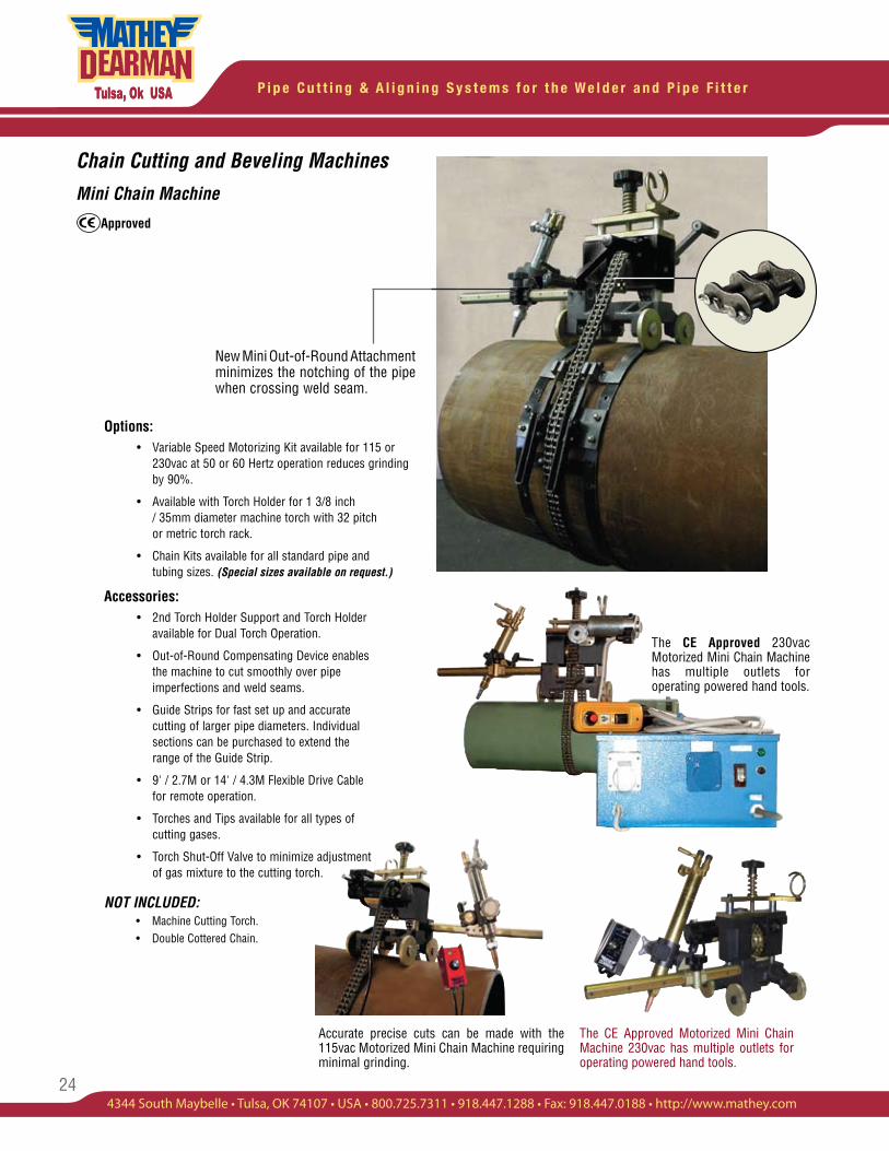
Most popular of the Chain Machines, the Lightweight Mini Chain Machine is recommended for cutting random lots of small
or larger diameters of pipe. Easily adjustable from one pipe size to another, the Mini follows the pipe outside diameter to produce a consistent bevel. The compact unit reduces down time and maintenance cost. The Mini Chain Machine's unique design delivers exceptional performance and maximum results. Cuts pipe diameters from 2" / 51mm to unlimited.
Chain Cutting and Beveling Machines
Mini Chain Machine
• BEST CHOICE for a small shop or maintenance facility.
• DURABLE and RUGGED enough to withstand the rigor of construction.
• VIRTUALLY ELIMINATES the need for more than one machine regardless of the pipe diameter.
• ACCURACY of the Mini Chain Machine is attained through its two wheel positions and DOUBLE Mesh Chain.
• Vertical pipe or vessels 18 inches / 457mm and larger can be accurately cut when used with the Guide Strips.
• The Rack Adjustable Torch Support allows the torch to pierce the pipe away from the cut line and be moved back to the cut line to reduce notching of the weld bevel.
• 50% FASTER than hand cutting and grinding.
(Chain Block with Pin Drive and Drive Chain ordered separately.)
Mini Chain Machines
Highly precise cut achieved on horizontal pipe when the Mini is used with a Guide Strip on 36" / 914mm pipe, Schedule 40.
Model Part Number Estimated
Shipping Weight(lbs. / kg)
Manual Mini 05.0520.000 34 / 15.4
Motorized Mini Chain Machine, 115vac 05.0520.M00 67 / 30.4
Motorized Mini Chain Machine, 2 outlets 230vac CE approved 05.0520.ME2 68 / 31
Motorized Mini Chain Machine, 3 outlets 230vac CE approved 05.0520.ME3 72 / 32.2
Mini Out-Of-Round Compensation Device 05.0520.300 7 / 3
230-115vac Stepdown Trans-former 01.0759.008 5.5 / 2.5
Approved
Cotter Pin Chain (Sold Separately.)
MINI Chain Machine Includes:
• Base Machine.• Torch Arm.• Service Keys.• Sliding Support.• Hose Support.• Torch Holder.• Parts and Operating Manual.
NOT INCLUDED:• Machine Cutting Torch.• Cotter Pin Chain. • Storage Box • Out-of-Round Compensating Device
Part No.: 05.0520.000
P i p e C u t t i n g & A l i g n i n g S y s t e m s f o r t h e W e l d e r a n d P i p e F i t t e r
24
Chain Cutting and Beveling Machines
Mini Chain Machine
Options: • Variable Speed Motorizing Kit available for 115 or 230vac at 50 or 60 Hertz operation reduces grinding by 90%.
• Available with Torch Holder for 1 3/8 inch / 35mm diameter machine torch with 32 pitch or metric torch rack.
• Chain Kits available for all standard pipe and tubing sizes. (Special sizes available on request.)
Accessories: • 2nd Torch Holder Support and Torch Holder available for Dual Torch Operation.
• Out-of-Round Compensating Device enables the machine to cut smoothly over pipe imperfections and weld seams.
• Guide Strips for fast set up and accurate cutting of larger pipe diameters. Individual sections can be purchased to extend the range of the Guide Strip.
• 9' / 2.7M or 14' / 4.3M Flexible Drive Cable for remote operation.
• Torches and Tips available for all types of cutting gases.
• Torch Shut-Off Valve to minimize adjustment of gas mixture to the cutting torch.
NOT INCLUDED: • Machine Cutting Torch. • Double Cottered Chain.
Accurate precise cuts can be made with the 115vac Motorized Mini Chain Machine requiring minimal grinding.
The CE Approved 230vac Motorized Mini Chain Machine has multiple outlets for operating powered hand tools.
Approved
New Mini Out-of-Round Attachment minimizes the notching of the pipe when crossing weld seam.
The CE Approved Motorized Mini Chain Machine 230vac has multiple outlets for operating powered hand tools.
25
P i p e C u t t i n g & A l i g n i n g S y s t e m s f o r t h e W e l d e r a n d P i p e F i t t e r
4344 South Maybelle • Tulsa, OK 74107 • USA • 800.725.7311 • 918.447.1288 • Fax: 918.447.0188 • http://www.mathey.com
Chain Cutting and Beveling Machines
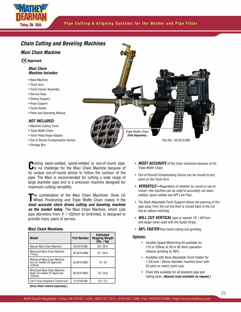
Maxi Chain Machine
Cutting seam-welded, spiral-welded or out-of-round pipe, is no challenge for the Maxi Chain Machine because of
its unique out-of-round device to follow the contour of the pipe. The Maxi is recommended for cutting a wide range of large diameter pipe and is a precision machine designed for maximum cutting versatility.
The combination of the Maxi Chain Machines' three (3) Wheel Positioning and Triple Width Chain makes it the
most accurate chain driven cutting and beveling machine on the market today. The Maxi Chain Machine, which cuts pipe diameters from 4" / 102mm to Unlimited, is designed to provide many years of service.
• MOST ACCURATE of the chain machines because of it’s Triple Width Chain.
• Out-of-Round Compensating Device can be moved to any point on the Torch Arm.
• VERSATILE—Regardless of whether its round or out-of- round—the machine can be used to accurately cut seam welded, spiral welded and API Line Pipe.
• The Rack Adjustable Torch Support allows the piercing of the pipe away from the cut line then is moved back to the cut line to reduce notching.
• WILL CUT VERTICAL pipe or vessels 18" / 457mm and larger when used with the Guide Strips.
• 50% FASTER than hand cutting and grinding.
Options: • Variable Speed Motorizing Kit available for 115 or 230vac at 50 or 60 Hertz operation reduces grinding by 90%.
• Available with Rack Adjustable Torch Holder for 1 3/8 inch / 35mm diameter machine torch with 32 pitch or metric torch rack.
• Chain Kits available for all standard pipe and tubing sizes. (Special sizes available on request.)
Maxi Chain Machines
Maxi Chain Machine Includes:
• Base Machine.• Torch Arm.• Torch Carrier Assembly.• Service Keys.• Sliding Support.• Hose Support.• Torch Holder.• Parts and Operating Manual.
NOT INCLUDED:• Machine Cutting Torch.• Triple Width Chain. • Torch Head Angle Adaptor • Out of Round Compensation Device. • Storage Box
Triple Width Chain (Sold Separately.)
(Drive Chain ordered separately.)
Model Part NumberEstimated
Shipping Weight (lbs. / kg)
Manual Maxi Chain Machine 05.0510.000 63 / 28.4
Motorized Maxi Chain Machine 115vac 05.0510.M00 67 / 30.4
Motorized Maxi Chain Machine two (2) outlets CE Approved -230vac
05.0510.ME2 73 / 33
Motorized Maxi Chain Machine three (3) outlets CE Approved -230vac
05.0510.ME3 79 / 35.8
230-115vac Stepdown Transformer 01.0759.008 5.5 / 2.5
Approved
Part No.: 05.0510.000
P i p e C u t t i n g & A l i g n i n g S y s t e m s f o r t h e W e l d e r a n d P i p e F i t t e r
26
Chain Machine
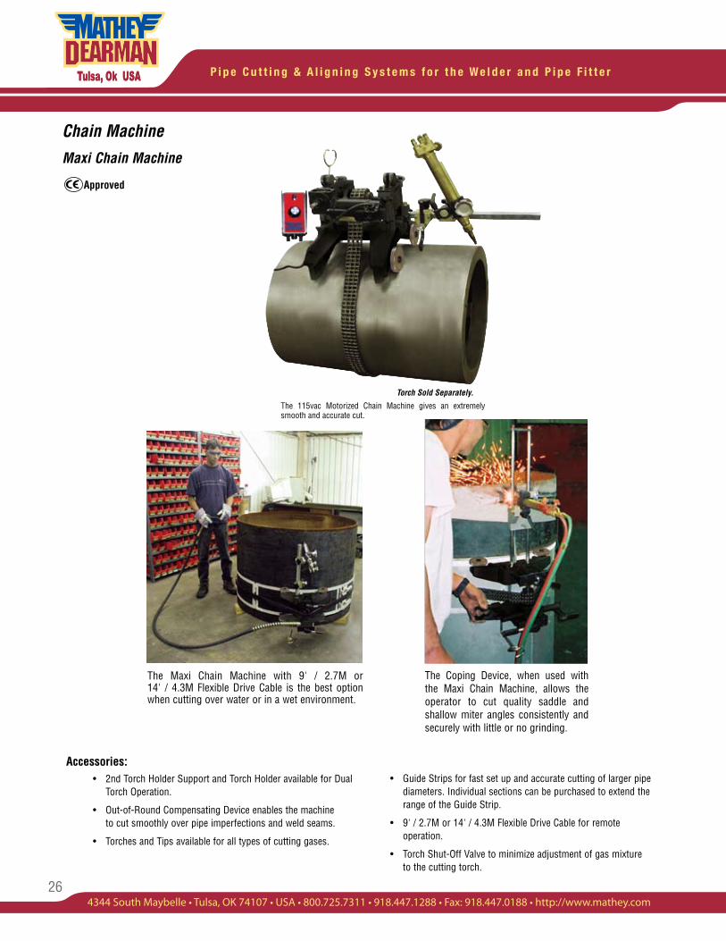
Maxi Chain Machine
The 115vac Motorized Chain Machine gives an extremely smooth and accurate cut.
Accessories: • 2nd Torch Holder Support and Torch Holder available for Dual Torch Operation.
• Out-of-Round Compensating Device enables the machine to cut smoothly over pipe imperfections and weld seams.
• Torches and Tips available for all types of cutting gases.
The Coping Device, when used with the Maxi Chain Machine, allows the operator to cut quality saddle and shallow miter angles consistently and securely with little or no grinding.
• Guide Strips for fast set up and accurate cutting of larger pipe diameters. Individual sections can be purchased to extend the range of the Guide Strip.
• 9' / 2.7M or 14' / 4.3M Flexible Drive Cable for remote operation.
• Torch Shut-Off Valve to minimize adjustment of gas mixture to the cutting torch.
The Maxi Chain Machine with 9' / 2.7M or 14' / 4.3M Flexible Drive Cable is the best option when cutting over water or in a wet environment.
Approved
Torch Sold Separately.
27
P i p e C u t t i n g & A l i g n i n g S y s t e m s f o r t h e W e l d e r a n d P i p e F i t t e r
4344 South Maybelle • Tulsa, OK 74107 • USA • 800.725.7311 • 918.447.1288 • Fax: 918.447.0188 • http://www.mathey.com
Chain Machine Accessories
Maxi and Mini Accessories
NOTE: A Step Down Transformer is also available for European Voltages.
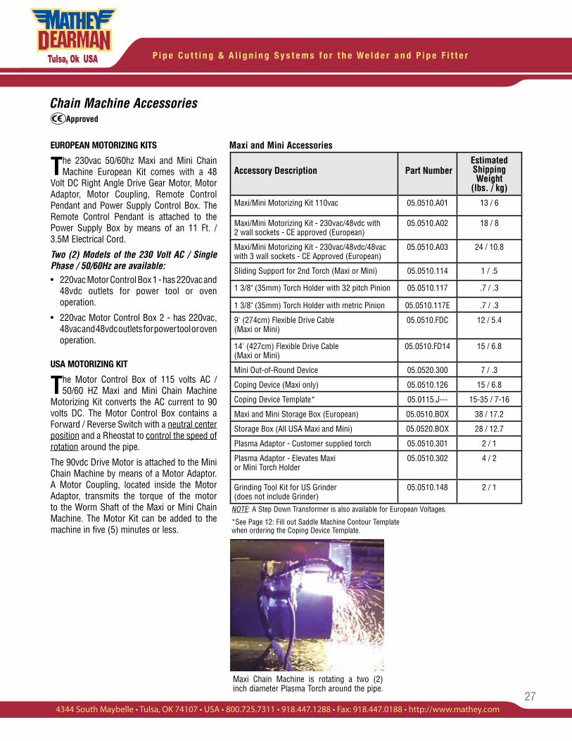
EUROPEAN MOTORIZING KITS
The 230vac 50/60hz Maxi and Mini Chain Machine European Kit comes with a 48
Volt DC Right Angle Drive Gear Motor, Motor Adaptor, Motor Coupling, Remote Control Pendant and Power Supply Control Box. The Remote Control Pendant is attached to the Power Supply Box by means of an 11 Ft. / 3.5M Electrical Cord.
Two (2) Models of the 230 Volt AC / Single Phase / 50/60Hz are available:• 220vac Motor Control Box 1 - has 220vac and 48vdc outlets for power tool or oven operation.
• 220vac Motor Control Box 2 - has 220vac, 48vac and 48vdc outlets for power tool or oven operation.
USA MOTORIZING KIT
The Motor Control Box of 115 volts AC / 50/60 HZ Maxi and Mini Chain Machine
Motorizing Kit converts the AC current to 90 volts DC. The Motor Control Box contains a Forward / Reverse Switch with a neutral center position and a Rheostat to control the speed of rotation around the pipe.
The 90vdc Drive Motor is attached to the Mini Chain Machine by means of a Motor Adaptor. A Motor Coupling, located inside the Motor Adaptor, transmits the torque of the motor to the Worm Shaft of the Maxi or Mini Chain Machine. The Motor Kit can be added to the machine in five (5) minutes or less.
*See Page 12: Fill out Saddle Machine Contour Template when ordering the Coping Device Template.
Accessory Description Part NumberEstimated Shipping Weight
(lbs. / kg)
Maxi/Mini Motorizing Kit 110vac 05.0510.A01 13 / 6
Maxi/Mini Motorizing Kit - 230vac/48vdc with 2 wall sockets - CE approved (European)
05.0510.A02 18 / 8
Maxi/Mini Motorizing Kit - 230vac/48vdc/48vac with 3 wall sockets - CE Approved (European)
05.0510.A03 24 / 10.8
Sliding Support for 2nd Torch (Maxi or Mini) 05.0510.114 1 / .5
1 3/8" (35mm) Torch Holder with 32 pitch Pinion 05.0510.117 .7 / .3
1 3/8" (35mm) Torch Holder with metric Pinion 05.0510.117E .7 / .3
9' (274cm) Flexible Drive Cable (Maxi or Mini)
05.0510.FDC 12 / 5.4
14' (427cm) Flexible Drive Cable (Maxi or Mini)
05.0510.FD14 15 / 6.8
Mini Out-of-Round Device 05.0520.300 7 / .3
Coping Device (Maxi only) 05.0510.126 15 / 6.8
Coping Device Template* 05.0115.J--- 15-35 / 7-16
Maxi and Mini Storage Box (European) 05.0510.BOX 38 / 17.2
Storage Box (All USA Maxi and Mini) 05.0520.BOX 28 / 12.7
Plasma Adaptor - Customer supplied torch 05.0510.301 2 / 1
Plasma Adaptor - Elevates Maxi or Mini Torch Holder
05.0510.302 4 / 2
Grinding Tool Kit for US Grinder (does not include Grinder)
05.0510.148 2 / 1
Maxi Chain Machine is rotating a two (2) inch diameter Plasma Torch around the pipe.
Approved
P i p e C u t t i n g & A l i g n i n g S y s t e m s f o r t h e W e l d e r a n d P i p e F i t t e r
28
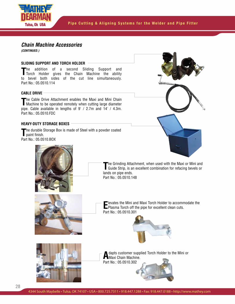
The Grinding Attachment, when used with the Maxi or Mini and Guide Strip, is an excellent combination for refacing bevels or
lands on pipe ends.Part No.: 05.0510.148
Elevates the Mini and Maxi Torch Holder to accommodate the Plasma Torch off the pipe for excellent clean cuts.
Part No.: 05.0510.301
Adapts customer supplied Torch Holder to the Mini or Maxi Chain Machine.
Part No.: 05.0510.302
SLIDING SUPPORT AND TORCH HOLDER
The addition of a second Sliding Support and Torch Holder gives the Chain Machine the ability
to bevel both sides of the cut line simultaneously. Part No.: 05.0510.114
CABLE DRIVE
The Cable Drive Attachment enables the Maxi and Mini Chain Machine to be operated remotely when cutting large diameter
pipe. Cable available in lengths of 9' / 2.7m and 14' / 4.3m. Part No.: 05.0510.FDC
HEAVY-DUTY STORAGE BOXES
The durable Storage Box is made of Steel with a powder coated paint finish.
Part No.: 05.0510.BOX
Chain Machine Accessories (CONTINUED.)
29
P i p e C u t t i n g & A l i g n i n g S y s t e m s f o r t h e W e l d e r a n d P i p e F i t t e r
4344 South Maybelle • Tulsa, OK 74107 • USA • 800.725.7311 • 918.447.1288 • Fax: 918.447.0188 • http://www.mathey.com
Chain Machine Accessories
Mini Chain Kits
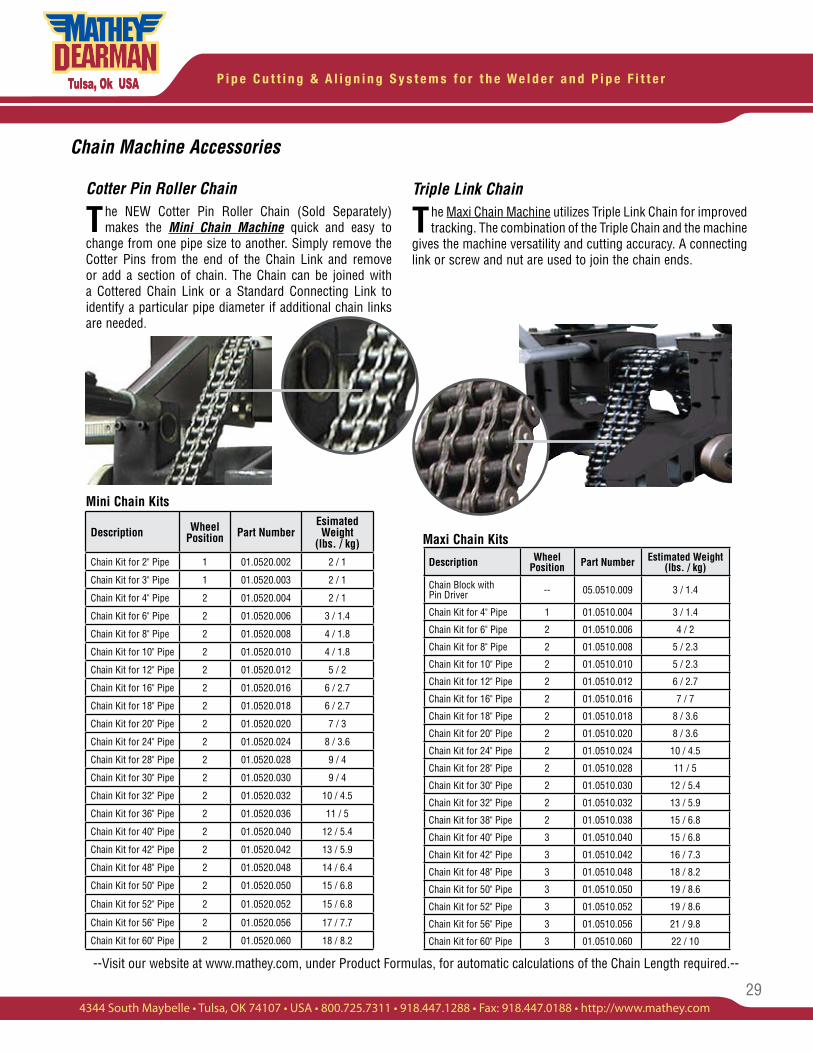
Triple Link Chain
The Maxi Chain Machine utilizes Triple Link Chain for improved tracking. The combination of the Triple Chain and the machine
gives the machine versatility and cutting accuracy. A connecting link or screw and nut are used to join the chain ends.
Description Wheel Position Part Number Estimated Weight
(lbs. / kg)
Chain Block with Pin Driver -- 05.0510.009 3 / 1.4
Chain Kit for 4" Pipe 1 01.0510.004 3 / 1.4
Chain Kit for 6" Pipe 2 01.0510.006 4 / 2
Chain Kit for 8" Pipe 2 01.0510.008 5 / 2.3
Chain Kit for 10" Pipe 2 01.0510.010 5 / 2.3
Chain Kit for 12" Pipe 2 01.0510.012 6 / 2.7
Chain Kit for 16" Pipe 2 01.0510.016 7 / 7
Chain Kit for 18" Pipe 2 01.0510.018 8 / 3.6
Chain Kit for 20" Pipe 2 01.0510.020 8 / 3.6
Chain Kit for 24" Pipe 2 01.0510.024 10 / 4.5
Chain Kit for 28" Pipe 2 01.0510.028 11 / 5
Chain Kit for 30" Pipe 2 01.0510.030 12 / 5.4
Chain Kit for 32" Pipe 2 01.0510.032 13 / 5.9
Chain Kit for 38" Pipe 2 01.0510.038 15 / 6.8
Chain Kit for 40" Pipe 3 01.0510.040 15 / 6.8
Chain Kit for 42" Pipe 3 01.0510.042 16 / 7.3
Chain Kit for 48" Pipe 3 01.0510.048 18 / 8.2
Chain Kit for 50" Pipe 3 01.0510.050 19 / 8.6
Chain Kit for 52" Pipe 3 01.0510.052 19 / 8.6
Chain Kit for 56" Pipe 3 01.0510.056 21 / 9.8
Chain Kit for 60" Pipe 3 01.0510.060 22 / 10
Description WheelPosition Part Number
Esimated Weight
(lbs. / kg)
Chain Kit for 2" Pipe 1 01.0520.002 2 / 1
Chain Kit for 3" Pipe 1 01.0520.003 2 / 1
Chain Kit for 4" Pipe 2 01.0520.004 2 / 1
Chain Kit for 6" Pipe 2 01.0520.006 3 / 1.4
Chain Kit for 8" Pipe 2 01.0520.008 4 / 1.8
Chain Kit for 10" Pipe 2 01.0520.010 4 / 1.8
Chain Kit for 12" Pipe 2 01.0520.012 5 / 2
Chain Kit for 16" Pipe 2 01.0520.016 6 / 2.7
Chain Kit for 18" Pipe 2 01.0520.018 6 / 2.7
Chain Kit for 20" Pipe 2 01.0520.020 7 / 3
Chain Kit for 24" Pipe 2 01.0520.024 8 / 3.6
Chain Kit for 28" Pipe 2 01.0520.028 9 / 4
Chain Kit for 30" Pipe 2 01.0520.030 9 / 4
Chain Kit for 32" Pipe 2 01.0520.032 10 / 4.5
Chain Kit for 36" Pipe 2 01.0520.036 11 / 5
Chain Kit for 40" Pipe 2 01.0520.040 12 / 5.4
Chain Kit for 42" Pipe 2 01.0520.042 13 / 5.9
Chain Kit for 48" Pipe 2 01.0520.048 14 / 6.4
Chain Kit for 50" Pipe 2 01.0520.050 15 / 6.8
Chain Kit for 52" Pipe 2 01.0520.052 15 / 6.8
Chain Kit for 56" Pipe 2 01.0520.056 17 / 7.7
Chain Kit for 60" Pipe 2 01.0520.060 18 / 8.2
--Visit our website at www.mathey.com, under Product Formulas, for automatic calculations of the Chain Length required.--
Cotter Pin Roller Chain
The NEW Cotter Pin Roller Chain (Sold Separately) makes the Mini Chain Machine quick and easy to
change from one pipe size to another. Simply remove the Cotter Pins from the end of the Chain Link and remove or add a section of chain. The Chain can be joined with a Cottered Chain Link or a Standard Connecting Link to identify a particular pipe diameter if additional chain links are needed.
Maxi Chain Kits
P i p e C u t t i n g & A l i g n i n g S y s t e m s f o r t h e W e l d e r a n d P i p e F i t t e r
30
Chain Machine Accessories
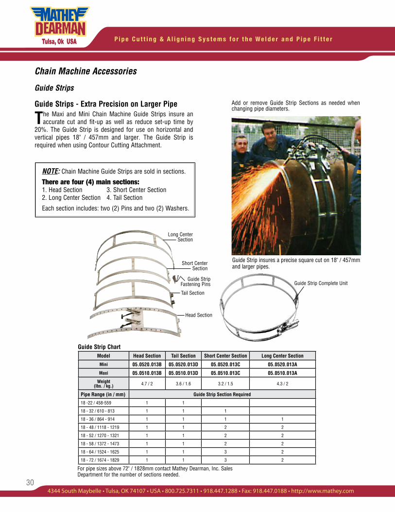
Guide Strips
Guide Strips - Extra Precision on Larger Pipe
The Maxi and Mini Chain Machine Guide Strips insure an accurate cut and fit-up as well as reduce set-up time by
20%. The Guide Strip is designed for use on horizontal and vertical pipes 18" / 457mm and larger. The Guide Strip is required when using Contour Cutting Attachment.
Add or remove Guide Strip Sections as needed when changing pipe diameters.
Guide Strip insures a precise square cut on 18" / 457mm and larger pipes.
Guide Strip Chart
For pipe sizes above 72" / 1828mm contact Mathey Dearman, Inc. Sales Department for the number of sections needed.
NOTE: Chain Machine Guide Strips are sold in sections.
There are four (4) main sections:1. Head Section 3. Short Center Section 2. Long Center Section 4. Tail Section
Each section includes: two (2) Pins and two (2) Washers.
Model Head Section Tail Section Short Center Section Long Center Section
Mini 05.0520.013B 05.0520.013D 05.0520.013C 05.0520.013A
Maxi 05.0510.013B 05.0510.013D 05.0510.013C 05.0510.013A
Weight (lbs. / kg.) 4.7 / 2 3.6 / 1.6 3.2 / 1.5 4.3 / 2
Pipe Range (in / mm) Guide Strip Section Required
18 -22 / 458-559 1 1
18 - 32 / 610 - 813 1 1 1
18 - 36 / 864 - 914 1 1 1 1
18 - 48 / 1118 - 1219 1 1 2 2
18 - 52 / 1270 - 1321 1 1 2 2
18 - 58 / 1372 - 1473 1 1 2 2
18 - 64 / 1524 - 1625 1 1 3 2
18 - 72 / 1674 - 1829 1 1 3 2
Long Center Section
Short Center Section
Guide Strip Fastening Pins
Tail Section
Head Section
Guide Strip Complete Unit
31
P i p e C u t t i n g & A l i g n i n g S y s t e m s f o r t h e W e l d e r a n d P i p e F i t t e r
4344 South Maybelle • Tulsa, OK 74107 • USA • 800.725.7311 • 918.447.1288 • Fax: 918.447.0188 • http://www.mathey.com
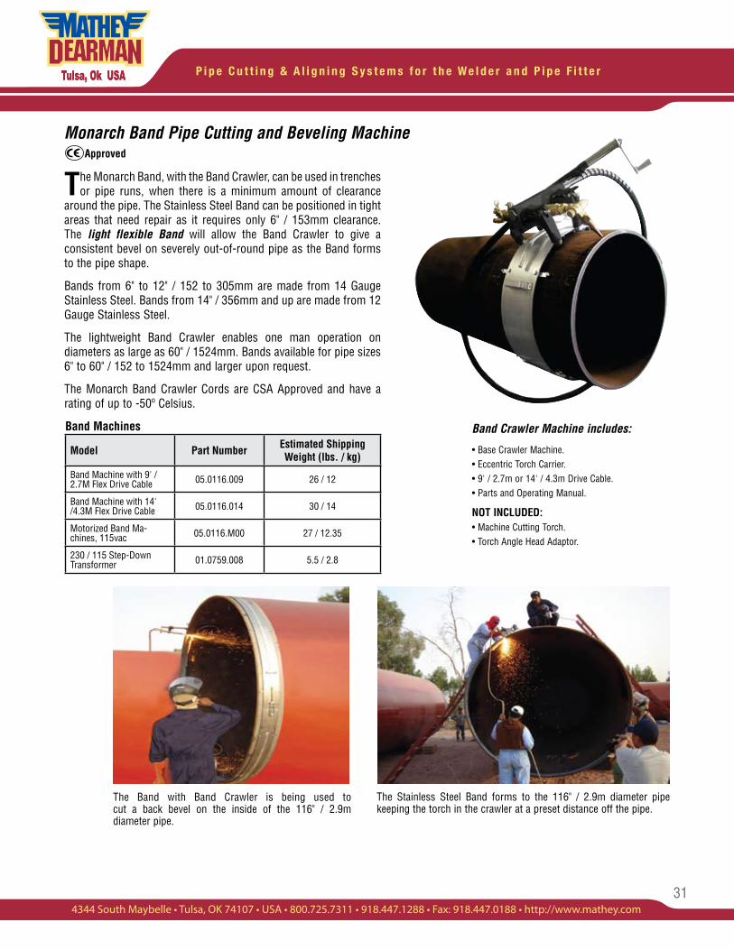
Monarch Band Pipe Cutting and Beveling Machine
The Monarch Band, with the Band Crawler, can be used in trenches or pipe runs, when there is a minimum amount of clearance
around the pipe. The Stainless Steel Band can be positioned in tight areas that need repair as it requires only 6" / 153mm clearance. The light flexible Band will allow the Band Crawler to give a consistent bevel on severely out-of-round pipe as the Band forms to the pipe shape.
Bands from 6" to 12" / 152 to 305mm are made from 14 Gauge Stainless Steel. Bands from 14" / 356mm and up are made from 12 Gauge Stainless Steel.
The lightweight Band Crawler enables one man operation on diameters as large as 60" / 1524mm. Bands available for pipe sizes 6" to 60" / 152 to 1524mm and larger upon request.
The Monarch Band Crawler Cords are CSA Approved and have a rating of up to -50º Celsius.
Band Machines Band Crawler Machine includes:
• Base Crawler Machine.• Eccentric Torch Carrier.• 9' / 2.7m or 14' / 4.3m Drive Cable.• Parts and Operating Manual.
NOT INCLUDED:• Machine Cutting Torch. • Torch Angle Head Adaptor.
Model Part Number Estimated Shipping Weight (lbs. / kg)
Band Machine with 9' / 2.7M Flex Drive Cable 05.0116.009 26 / 12
Band Machine with 14' /4.3M Flex Drive Cable 05.0116.014 30 / 14
Motorized Band Ma-chines, 115vac 05.0116.M00 27 / 12.35
230 / 115 Step-Down Transformer 01.0759.008 5.5 / 2.8
The Stainless Steel Band forms to the 116" / 2.9m diameter pipe keeping the torch in the crawler at a preset distance off the pipe.
The Band with Band Crawler is being used to cut a back bevel on the inside of the 116" / 2.9m diameter pipe.
Approved
P i p e C u t t i n g & A l i g n i n g S y s t e m s f o r t h e W e l d e r a n d P i p e F i t t e r
32
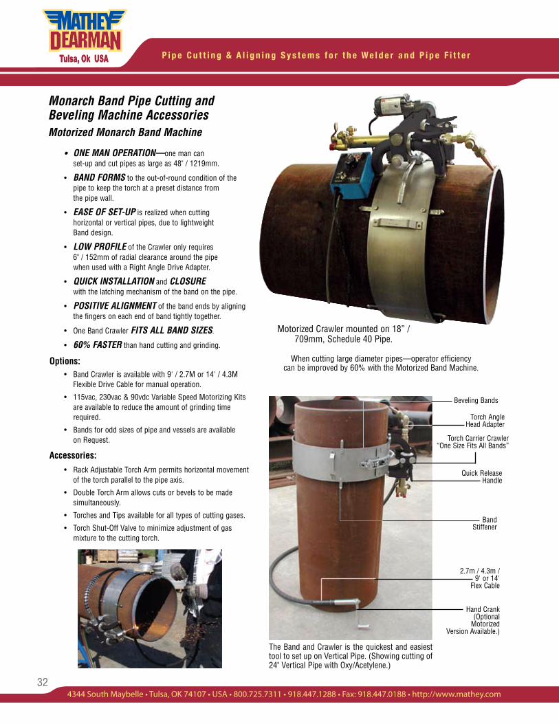
When cutting large diameter pipes—operator efficiency can be improved by 60% with the Motorized Band Machine.
Monarch Band Pipe Cutting and Beveling Machine AccessoriesMotorized Monarch Band Machine
• ONE MAN OPERATION—one man can set-up and cut pipes as large as 48" / 1219mm.
• BAND FORMS to the out-of-round condition of the pipe to keep the torch at a preset distance from the pipe wall.
• EASE OF SET-UP is realized when cutting horizontal or vertical pipes, due to lightweight Band design.
• LOW PROFILE of the Crawler only requires 6" / 152mm of radial clearance around the pipe when used with a Right Angle Drive Adapter.
• QUICK INSTALLATION and CLOSURE with the latching mechanism of the band on the pipe.
• POSITIVE ALIGNMENT of the band ends by aligning the fingers on each end of band tightly together.
• One Band Crawler FITS ALL BAND SIZES.
• 60% FASTER than hand cutting and grinding.
Options: • Band Crawler is available with 9' / 2.7M or 14' / 4.3M Flexible Drive Cable for manual operation.
• 115vac, 230vac & 90vdc Variable Speed Motorizing Kits are available to reduce the amount of grinding time required.
• Bands for odd sizes of pipe and vessels are available on Request.
Accessories: • Rack Adjustable Torch Arm permits horizontal movement of the torch parallel to the pipe axis.
• Double Torch Arm allows cuts or bevels to be made simultaneously.
• Torches and Tips available for all types of cutting gases.
• Torch Shut-Off Valve to minimize adjustment of gas mixture to the cutting torch.
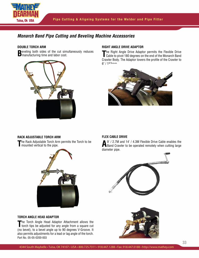
The Band and Crawler is the quickest and easiest tool to set up on Vertical Pipe. (Showing cutting of 24" Vertical Pipe with Oxy/Acetylene.)
2.7m / 4.3m / 9' or 14'
Flex Cable
Hand Crank (Optional
Motorized Version Available.)
Torch Angle Head Adapter
Torch Carrier Crawler “One Size Fits All Bands”
Quick Release Handle
Motorized Crawler mounted on 18” / 709mm, Schedule 40 Pipe.
Beveling Bands
Band Stiffener
33
P i p e C u t t i n g & A l i g n i n g S y s t e m s f o r t h e W e l d e r a n d P i p e F i t t e r
4344 South Maybelle • Tulsa, OK 74107 • USA • 800.725.7311 • 918.447.1288 • Fax: 918.447.0188 • http://www.mathey.com
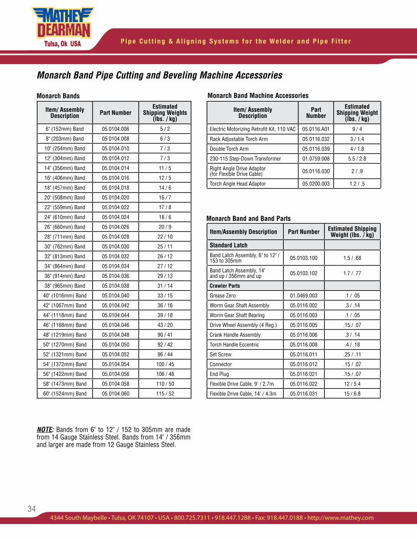
DOUBLE TORCH ARM
Beveling both sides of the cut simultaneously reduces manufacturing time and labor cost.
RACK ADJUSTABLE TORCH ARM
The Rack Adjustable Torch Arm permits the Torch to be mounted vertical to the pipe.
TORCH ANGLE HEAD ADAPTOR
The Torch Angle Head Adaptor Attachment allows the torch tips be adjusted for any angle from a square cut
(no bevel), to a bevel angle up to 90 degrees V-Groove. It also permits adjustments for a lead or lag angle of the torch. Part No. 05-05-0200-003
RIGHT ANGLE DRIVE ADAPTOR
The Right Angle Drive Adaptor permits the Flexible Drive Cable to pivot 180 degrees on the end of the Monarch Band
Crawler Body. The Adaptor lowers the profile of the Crawler to 6" / 153mm.
FLEX CABLE DRIVE
A9' / 2.7M and 14' / 4.3M Flexible Drive Cable enables the Band Crawler to be operated remotely when cutting large
diameter pipe.
Monarch Band Pipe Cutting and Beveling Machine Accessories
P i p e C u t t i n g & A l i g n i n g S y s t e m s f o r t h e W e l d e r a n d P i p e F i t t e r
34
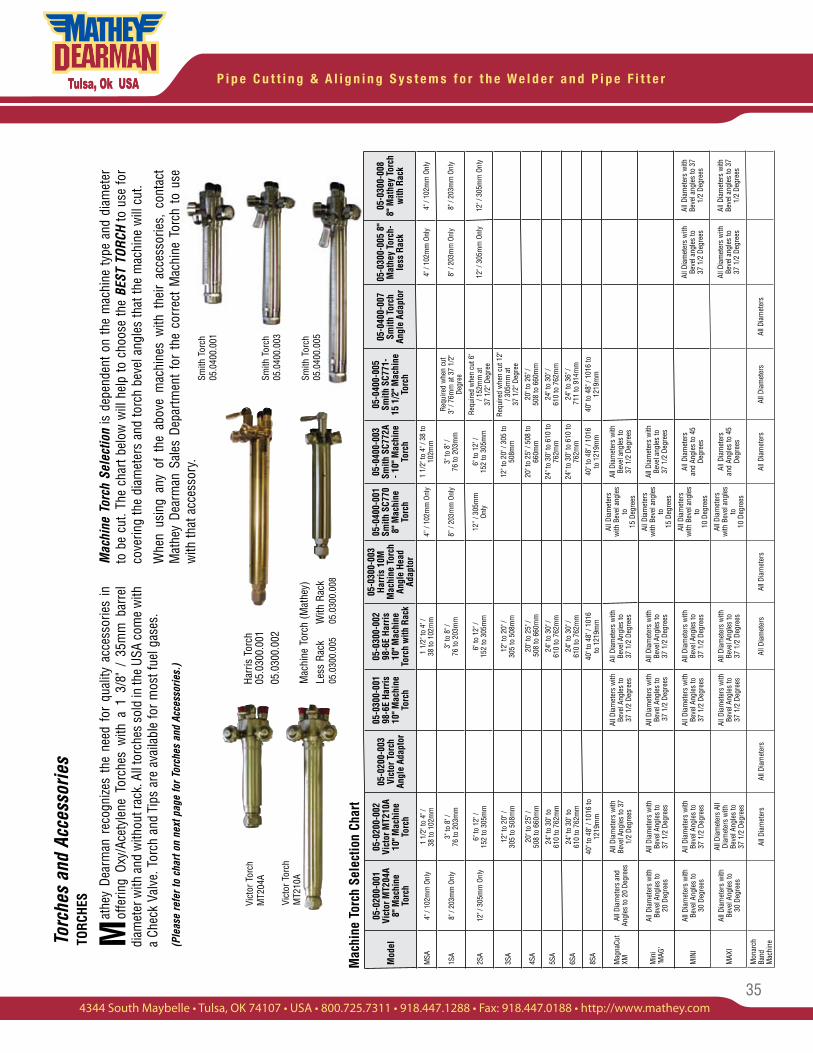
Monarch Band Pipe Cutting and Beveling Machine Accessories
Monarch Bands
NOTE: Bands from 6" to 12" / 152 to 305mm are made from 14 Gauge Stainless Steel. Bands from 14" / 356mm and larger are made from 12 Gauge Stainless Steel.
Monarch Band Machine Accessories
Monarch Band and Band Parts
Item/ AssemblyDescription Part Number
Estimated Shipping Weights
(lbs. / kg)
6" (152mm) Band 05.0104.006 5 / 2
8" (203mm) Band 05.0104.008 6 / 3
10" (254mm) Band 05.0104.010 7 / 3
12" (304mm) Band 05.0104.012 7 / 3
14" (356mm) Band 05.0104.014 11 / 5
16" (406mm) Band 05.0104.016 12 / 5
18" (457mm) Band 05.0104.018 14 / 6
20" (508mm) Band 05.0104.020 16 / 7
22" (559mm) Band 05.0104.022 17 / 8
24" (610mm) Band 05.0104.024 18 / 6
26" (660mm) Band 05.0104.026 20 / 9
28" (711mm) Band 05.0104.028 22 / 10
30" (762mm) Band 05.0104.030 25 / 11
32" (813mm) Band 05.0104.032 26 / 12
34" (864mm) Band 05.0104.034 27 / 12
36" (914mm) Band 05.0104.036 29 / 13
38" (965mm) Band 05.0104.038 31 / 14
40" (1016mm) Band 05.0104.040 33 / 15
42" (1067mm) Band 05.0104.042 36 / 16
44" (1118mm) Band 05.0104.044 39 / 18
46" (1168mm) Band 05.0104.046 43 / 20
48" (1219mm) Band 05.0104.048 90 / 41
50" (1270mm) Band 05.0104.050 92 / 42
52" (1321mm) Band 05.0104.052 96 / 44
54" (1372mm) Band 05.0104.054 100 / 45
56" (1422mm) Band 05.0104.056 106 / 48
58" (1473mm) Band 05.0104.058 110 / 50
60" (1524mm) Band 05.0104.060 115 / 52
Item/Assembly Description Part Number Estimated Shipping Weight (lbs. / kg)
Standard Latch
Band Latch Assembly, 6" to 12" / 153 to 305mm 05.0103.100 1.5 / .68
Band Latch Assembly, 14" and up / 356mm and up 05.0103.102 1.7 / .77
Crawler Parts
Grease Zero 01.0469.003 .1 / .05
Worm Gear Shaft Assembly 05.0116.002 .3 / .14
Worm Gear Shaft Bearing 05.0116.003 .1 / .05
Drive Wheel Assembly (4 Reg.) 05.0116.005 .15 / .07
Crank Handle Assembly 05.0116.006 .3 / .14
Torch Handle Eccentric 05.0116.008 .4 / .18
Set Screw 05.0116.011 .25 / .11
Connector 05.0116.012 .15 / .07
End Plug 05.0116.021 .15 / .07
Flexible Drive Cable, 9' / 2.7m 05.0116.022 12 / 5.4
Flexible Drive Cable, 14' / 4.3m 05.0116.031 15 / 6.8
Item/ Assembly Description
Part Number
Estimated Shipping Weight
(lbs. / kg)
Electric Motorizing Retrofit Kit, 110 VAC 05.0116.A01 9 / 4
Rack Adjustable Torch Arm 05.0116.032 3 / 1.4
Double Torch Arm 05.0116.039 4 / 1.8
230-115 Step-Down Transformer 01.0759.008 5.5 / 2.8
Right Angle Drive Adaptor (for Flexible Drive Cable) 05.0116.030 2 / .9
Torch Angle Head Adaptor 05.0200.003 1.2 / .5
35
P i p e C u t t i n g & A l i g n i n g S y s t e m s f o r t h e W e l d e r a n d P i p e F i t t e r
4344 South Maybelle • Tulsa, OK 74107 • USA • 800.725.7311 • 918.447.1288 • Fax: 918.447.0188 • http://www.mathey.com
Mac
hine
Tor
ch S
elec
tion
Char
t
Mac
hine
Tor
ch S
elec
tion
is d
epen
dent
on
the
mac
hine
type
and
dia
met
er
to b
e cu
t. Th
e ch
art b
elow
will
hel
p to
cho
ose
the
BEST
TOR
CH to
use
for
cove
ring
the
diam
eter
s an
d to
rch
beve
l ang
les
that
the
mac
hine
will
cut
.
Whe
n us
ing
any
of t
he a
bove
mac
hine
s w
ith t
heir
acce
ssor
ies,
con
tact
M
athe
y De
arm
an S
ales
Dep
artm
ent
for
the
corr
ect
Mac
hine
Tor
ch t
o us
e w
ith th
at a
cces
sory
.
Torc
hes
and
Acce
ssor
ies
Vict
or T
orch
M
T210
A
Vict
or T
orch
M
T204
A
Mac
hine
Tor
ch (M
athe
y)
Less
Rac
k W
ith R
ack
05.0
300.
005
05.0
300.
008
Harr
is T
orch
05
.030
0.00
105
.030
0.00
2
TOR
CHES
Mat
hey
Dear
man
rec
ogni
zes
the
need
for
qua
lity
acce
ssor
ies
in
offe
ring
Oxy/
Acet
ylen
e To
rche
s w
ith a
1 3
/8"
/ 35
mm
bar
rel
diam
eter
with
and
with
out r
ack.
All
torc
hes
sold
in th
e US
A co
me
with
a
Chec
k Va
lve.
Tor
ch a
nd T
ips
are
avai
labl
e fo
r mos
t fue
l gas
es.
(Ple
ase
refe
r to
char
t on
next
pag
e fo
r Tor
ches
and
Acc
esso
ries.
)
Smith
Tor
ch
05.0
400.
001
Smith
Tor
ch
05.0
400.
003
Smith
Tor
ch
05.0
400.
005
Mod
el
05-0
200-
001
Vict
or M
T204
A 8"
Mac
hine
To
rch
05-0
200-
002
Vict
or M
T210
A 10
" Mac
hine
To
rch
05-0
200-
003
Vict
or T
orch
An
gle
Adap
tor
05-0
300-
001
98-6
E Ha
rris
10
" Mac
hine
To
rch
05-0
300-
002
98
-6E
Harr
is
10" M
achi
ne
Torc
h w
ith R
ack
05-0
300-
003
Harr
is 1
0M
Mac
hine
Tor
ch
Angl
e He
ad
Adap
tor
05-0
400-
001
Smith
SC7
70
8" M
achi
ne
Torc
h
05-0
400-
003
Smith
SC7
72A
- 10"
Mac
hine
To
rch
05-0
400-
005
Smith
SC7
71-
15 1
/2" M
achi
ne
Torc
h
05-0
400-
007
Smith
Tor
ch
Angl
e Ad
apto
r
05-0
300-
005
8"
Mat
hey
Torc
h-le
ss R
ack
05-0
300-
008
8"
Mat
hey
Torc
h w
ith R
ack
MSA
4" /
102m
m O
nly
1 1/
2" to
4" /
38
to 1
02m
m1
1/2"
to 4
" /
38 to
102
mm
4” /
102m
m O
nly
1 1/
2" to
4" /
38
to
102m
m4"
/ 10
2mm
Onl
y4"
/ 10
2mm
Onl
y
1SA
8" /
203m
m O
nly
3" to
8" /
76
to 2
03m
m3"
to 8
" /
76 to
203
mm
8” /
203m
m O
nly
3" to
8" /
76
to 2
03m
m
Requ
ired
whe
n cu
t 3"
/ 76
mm
at 3
7 1/
2"
Degr
ee8"
/ 20
3mm
Onl
y8"
/ 20
3mm
Onl
y
2SA
12" /
305
mm
Onl
y6"
to 1
2" /
15
2 to
305
mm
6" to
12"
/ 15
2 to
305
mm
12”
/ 305
mm
On
ly6"
to 1
2" /
152
to 3
05m
m
Requ
ired
whe
n cu
t 6"
/ 152
mm
at
37 1
/2" D
egre
e
12" /
305
mm
Onl
y12
" / 3
05m
m O
nly
3SA
12" t
o 20
" /
305
to 5
08m
m12
" to
20" /
30
5 to
508
mm
12" t
o 20
" / 3
05 to
50
8mm
Requ
ired
whe
n cu
t 12"
/ 3
05m
m a
t 37
1/2
" Deg
ree
4SA
20" t
o 25
" /
508
to 6
60m
m20
" to
25" /
5
08 to
660
mm
20" t
o 25
" / 5
08 to
66
0mm
20" t
o 26
" /
508
to 6
60m
m
5SA
24" t
o 30
" to
61
0 to
762
mm
24" t
o 30
" /
610
to 7
62m
m24
" to
30" t
o 61
0 to
76
2mm
24" t
o 30
" /
610
to 7
62m
m
6SA
24" t
o 30
" to
61
0 to
762
mm
24" t
o 30
" /
610
to 7
62m
m24
" to
30" t
o 61
0 to
76
2mm
24" t
o 36
" /
711
to 9
14m
m
8SA
40" t
o 48
" / 1
016
to
1219
mm
40" t
o 48
" / 1
016
to
121
9mm
40" t
o 48
" / 1
016
to
121
9mm
40" t
o 48
" / 1
016
to
1219
mm
Mag
naCu
t XM
All D
iam
eter
s an
d An
gles
to 2
0 De
gree
s
All D
iam
eter
s w
ith
Beve
l Ang
les
to 3
7 1/
2 De
gree
s
All D
iam
eter
s w
ith
Beve
l Ang
les
to
37 1
/2 D
egre
es
All D
iam
eter
s w
ith
Beve
l Ang
les
to
37 1
/2 D
egre
es
All D
iam
eter
s w
ith B
evel
ang
les
to
15 D
egre
es
All D
iam
eter
s w
ith
Beve
l ang
les
to
37 1
/2 D
egre
es
Min
i 'M
AG'
All D
iam
eter
s w
ith
Beve
l Ang
les
to
20 D
egre
es
All D
iam
eter
s w
ith
Beve
l Ang
les
to
37 1
/2 D
egre
es
All D
iam
eter
s w
ith
Beve
l Ang
les
to
37
1/2
Degr
ees
All D
iam
eter
s w
ith
Beve
l Ang
les
to
37 1
/2 D
egre
es
All D
iam
eter
s w
ith B
evel
ang
les
to
15 D
egre
es
All D
iam
eter
s w
ith
Beve
l ang
les
to
37 1
/2 D
egre
es
MIN
IAl
l Dia
met
ers
with
Be
vel A
ngle
s to
30
Deg
rees
All D
iam
eter
s w
ith
Beve
l Ang
les
to
37 1
/2 D
egre
es
All D
iam
eter
s w
ith
Beve
l Ang
les
to
37 1
/2 D
egre
es
All D
iam
eter
s w
ith
Beve
l Ang
les
to
37 1
/2 D
egre
es
All D
iam
eter
s w
ith B
evel
ang
les
to
10 D
egre
es
All D
iam
eter
s an
d An
gles
to 4
5 De
gree
s
All D
iam
eter
s w
ith
Beve
l ang
les
to
37 1
/2 D
egre
es
All D
iam
eter
s w
ith
Beve
l ang
les
to 3
7 1/
2 De
gree
s
MAX
IAl
l Dia
met
ers
with
Be
vel A
ngle
s to
30
Deg
rees
All D
iam
eter
s Al
l Di
amet
ers
with
Be
vel A
ngle
s to
37
1/2
Deg
rees
All D
iam
eter
s w
ith
Beve
l Ang
les
to
37 1
/2 D
egre
es
All D
iam
eter
s w
ith
Beve
l Ang
les
to
37 1
/2 D
egre
es
All D
iam
eter
s w
ith B
evel
ang
les
to
10 D
egre
es
All D
iam
eter
s an
d An
gles
to 4
5 De
gree
s
All D
iam
eter
s w
ith
Beve
l ang
les
to
37 1
/2 D
egre
es
All D
iam
eter
s w
ith
Beve
l ang
les
to 3
7 1/
2 De
gree
s
Mon
arch
Ba
nd
Mac
hine
All D
iam
eter
sAl
l Dia
met
ers
All D
iam
eter
sAl
l Dia
met
ers
All D
iam
eter
sAl
l Dia
met
ers
All D
iam
eter
s
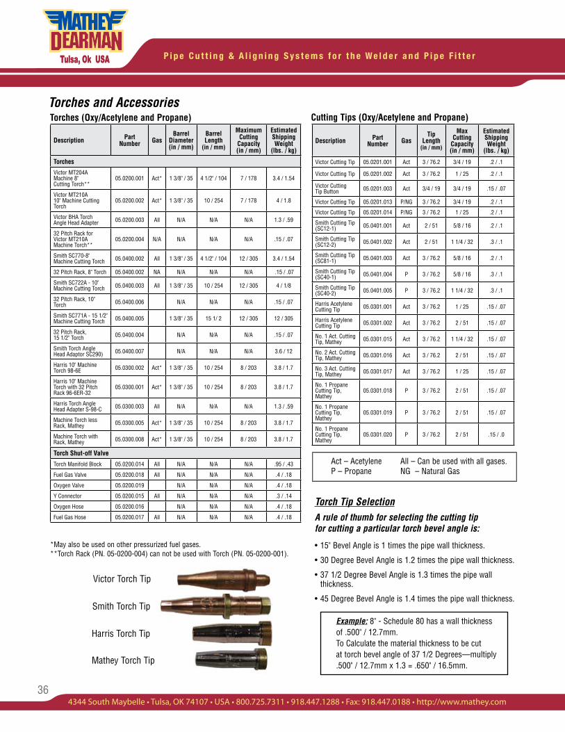
P i p e C u t t i n g & A l i g n i n g S y s t e m s f o r t h e W e l d e r a n d P i p e F i t t e r
36
Torches (Oxy/Acetylene and Propane)Torches and Accessories
Cutting Tips (Oxy/Acetylene and Propane)
*May also be used on other pressurized fuel gases. **Torch Rack (PN. 05-0200-004) can not be used with Torch (PN. 05-0200-001).
Victor Torch Tip
Torch Tip SelectionA rule of thumb for selecting the cutting tip for cutting a particular torch bevel angle is:
15" Bevel Angle is 1 times the pipe wall thickness.•
30 Degree Bevel Angle is 1.2 times the pipe wall thickness.•
37 1/2 Degree Bevel Angle is 1.3 times the pipe wall • thickness.
45 Degree Bevel Angle is 1.4 times the pipe wall thickness.•
Act – Acetylene All – Can be used with all gases. P – Propane NG – Natural Gas
Harris Torch Tip
Mathey Torch Tip
Description Part Number Gas
Barrel Diameter (in / mm)
Barrel Length
(in / mm)
Maximum Cutting
Capacity (in / mm)
Estimated Shipping Weight
(lbs. / kg)
Torches
Victor MT204A Machine 8" Cutting Torch**
05.0200.001 Act* 1 3/8" / 35 4 1/2" / 104 7 / 178 3.4 / 1.54
Victor MT210A 10" Machine Cutting Torch
05.0200.002 Act* 1 3/8" / 35 10 / 254 7 / 178 4 / 1.8
Victor BHA Torch Angle Head Adapter 05.0200.003 All N/A N/A N/A 1.3 / .59
32 Pitch Rack for Victor MT210A Machine Torch**
05.0200.004 N/A N/A N/A N/A .15 / .07
Smith SC770-8" Machine Cutting Torch 05.0400.002 All 1 3/8" / 35 4 1/2" / 104 12 / 305 3.4 / 1.54
32 Pitch Rack, 8" Torch 05.0400.002 NA N/A N/A N/A .15 / .07
Smith SC722A - 10" Machine Cutting Torch 05.0400.003 All 1 3/8" / 35 10 / 254 12 / 305 4 / 1/8
32 Pitch Rack, 10" Torch 05.0400.006 N/A N/A N/A .15 / .07
Smith SC771A - 15 1/2" Machine Cutting Torch 05.0400.005 1 3/8" / 35 15 1/ 2 12 / 305 12 / 305
32 Pitch Rack, 15 1/2" Torch 05.0400.004 N/A N/A N/A .15 / .07
Smith Torch Angle Head Adaptor SC290) 05.0400.007 N/A N/A N/A 3.6 / 12
Harris 10" Machine Torch 98-6E 05.0300.002 Act* 1 3/8" / 35 10 / 254 8 / 203 3.8 / 1.7
Harris 10" Machine Torch with 32 Pitch Rack 96-6ER-32
05.0300.001 Act* 1 3/8" / 35 10 / 254 8 / 203 3.8 / 1.7
Harris Torch Angle Head Adapter S-98-C 05.0300.003 All N/A N/A N/A 1.3 / .59
Machine Torch less Rack, Mathey 05.0300.005 Act* 1 3/8" / 35 10 / 254 8 / 203 3.8 / 1.7
Machine Torch with Rack, Mathey 05.0300.008 Act* 1 3/8" / 35 10 / 254 8 / 203 3.8 / 1.7
Torch Shut-off Valve
Torch Manifold Block 05.0200.014 All N/A N/A N/A .95 / .43
Fuel Gas Valve 05.0200.018 All N/A N/A N/A .4 / .18
Oxygen Valve 05.0200.019 N/A N/A N/A .4 / .18
Y Connector 05.0200.015 All N/A N/A N/A .3 / .14
Oxygen Hose 05.0200.016 N/A N/A N/A .4 / .18
Fuel Gas Hose 05.0200.017 All N/A N/A N/A .4 / .18
Description Part Number Gas
Tip Length
(in / mm)
Max Cutting
Capacity (in / mm)
Estimated Shipping Weight
(lbs. / kg)
Victor Cutting Tip 05.0201.001 Act 3 / 76.2 3/4 / 19 .2 / .1
Victor Cutting Tip 05.0201.002 Act 3 / 76.2 1 / 25 .2 / .1
Victor Cutting Tip Button 05.0201.003 Act 3/4 / 19 3/4 / 19 .15 / .07
Victor Cutting Tip 05.0201.013 P/NG 3 / 76.2 3/4 / 19 .2 / .1
Victor Cutting Tip 05.0201.014 P/NG 3 / 76.2 1 / 25 .2 / .1
Smith Cutting Tip (SC12-1) 05.0401.001 Act 2 / 51 5/8 / 16 .2 / .1
Smith Cutting Tip (SC12-2) 05.0401.002 Act 2 / 51 1 1/4 / 32 .3 / .1
Smith Cutting Tip (SC81-1) 05.0401.003 Act 3 / 76.2 5/8 / 16 .2 / .1
Smith Cutting Tip (SC40-1) 05.0401.004 P 3 / 76.2 5/8 / 16 .3 / .1
Smith Cutting Tip (SC40-2) 05.0401.005 P 3 / 76.2 1 1/4 / 32 .3 / .1
Harris Acetylene Cutting Tip 05.0301.001 Act 3 / 76.2 1 / 25 .15 / .07
Harris Acetylene Cutting Tip 05.0301.002 Act 3 / 76.2 2 / 51 .15 / .07
No. 1 Act. Cutting Tip, Mathey 05.0301.015 Act 3 / 76.2 1 1/4 / 32 .15 / .07
No. 2 Act. Cutting Tip, Mathey 05.0301.016 Act 3 / 76.2 2 / 51 .15 / .07
No. 3 Act. Cutting Tip, Mathey 05.0301.017 Act 3 / 76.2 1 / 25 .15 / .07
No. 1 Propane Cutting Tip, Mathey
05.0301.018 P 3 / 76.2 2 / 51 .15 / .07
No. 1 Propane Cutting Tip, Mathey
05.0301.019 P 3 / 76.2 2 / 51 .15 / .07
No. 1 Propane Cutting Tip, Mathey
05.0301.020 P 3 / 76.2 2 / 51 .15 / .0
Smith Torch Tip
Example: 8" - Schedule 80 has a wall thickness of .500" / 12.7mm. To Calculate the material thickness to be cut at torch bevel angle of 37 1/2 Degrees—multiply .500" / 12.7mm x 1.3 = .650" / 16.5mm.
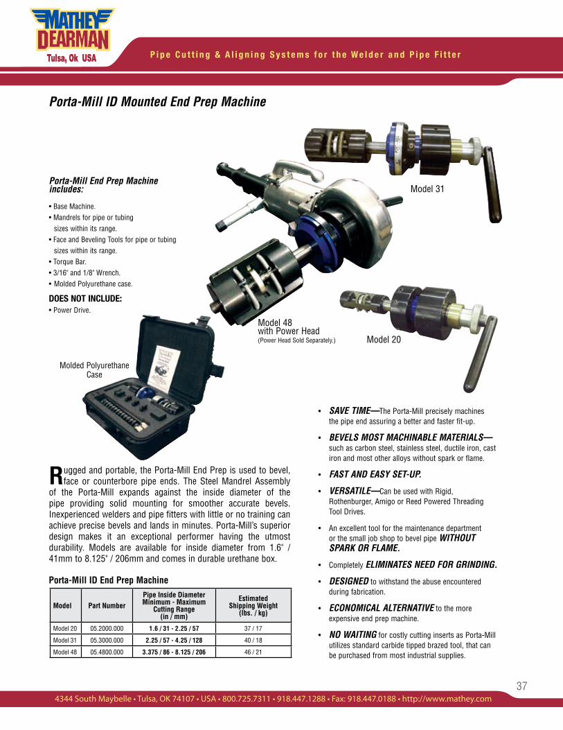
37
P i p e C u t t i n g & A l i g n i n g S y s t e m s f o r t h e W e l d e r a n d P i p e F i t t e r
4344 South Maybelle • Tulsa, OK 74107 • USA • 800.725.7311 • 918.447.1288 • Fax: 918.447.0188 • http://www.mathey.com
Rugged and portable, the Porta-Mill End Prep is used to bevel, face or counterbore pipe ends. The Steel Mandrel Assembly
of the Porta-Mill expands against the inside diameter of the pipe providing solid mounting for smoother accurate bevels. Inexperienced welders and pipe fitters with little or no training can achieve precise bevels and lands in minutes. Porta-Mill’s superior design makes it an exceptional performer having the utmost durability. Models are available for inside diameter from 1.6" / 41mm to 8.125" / 206mm and comes in durable urethane box.
Porta-Mill ID End Prep Machine
• SAVE TIME—The Porta-Mill precisely machines the pipe end assuring a better and faster fit-up.
• BEVELS MOST MACHINABLE MATERIALS— such as carbon steel, stainless steel, ductile iron, cast iron and most other alloys without spark or flame.
• FAST AND EASY SET-UP.
• VERSATILE—Can be used with Rigid, Rothenburger, Amigo or Reed Powered Threading Tool Drives.
• An excellent tool for the maintenance department or the small job shop to bevel pipe WITHOUT SPARK OR FLAME.
• Completely ELIMINATES NEED FOR GRINDING.
• DESIGNED to withstand the abuse encountered during fabrication.
• ECONOMICAL ALTERNATIVE to the more expensive end prep machine.
• NO WAITING for costly cutting inserts as Porta-Mill utilizes standard carbide tipped brazed tool, that can be purchased from most industrial supplies.
Porta-Mill ID Mounted End Prep Machine
Model 48 with Power Head (Power Head Sold Separately.)
Model 31Porta-Mill End Prep Machine includes:
• Base Machine.• Mandrels for pipe or tubing sizes within its range.• Face and Beveling Tools for pipe or tubing sizes within its range.• Torque Bar.• 3/16" and 1/8" Wrench.• Molded Polyurethane case.
DOES NOT INCLUDE:• Power Drive.
Model 20
Model Part NumberPipe Inside Diameter Minimum - Maximum
Cutting Range (in / mm)
Estimated Shipping Weight
(lbs. / kg)
Model 20 05.2000.000 1.6 / 31 - 2.25 / 57 37 / 17
Model 31 05.3000.000 2.25 / 57 - 4.25 / 128 40 / 18
Model 48 05.4800.000 3.375 / 86 - 8.125 / 206 46 / 21
Molded Polyurethane Case
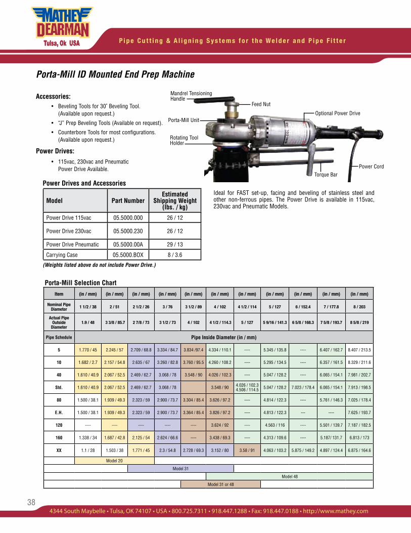
P i p e C u t t i n g & A l i g n i n g S y s t e m s f o r t h e W e l d e r a n d P i p e F i t t e r
38
Accessories: • Beveling Tools for 30˚ Beveling Tool. (Available upon request.)
• “J” Prep Beveling Tools (Available on request).
• Counterbore Tools for most configurations. (Available upon request.)
Power Drives: • 115vac, 230vac and Pneumatic Power Drive Available.
Mandrel Tensioning Handle
Feed Nut
Porta-Mill UnitOptional Power Drive
Power CordTorque Bar
Rotating Tool Holder
(Weights listed above do not include Power Drive.)
Power Drives and Accessories
Porta-Mill ID Mounted End Prep Machine
Model Part NumberEstimated
Shipping Weight (lbs. / kg)
Power Drive 115vac 05.5000.000 26 / 12
Power Drive 230vac 05.5000.230 26 / 12
Power Drive Pneumatic 05.5000.00A 29 / 13
Carrying Case 05.5000.BOX 8 / 3.6
Ideal for FAST set-up, facing and beveling of stainless steel and other non-ferrous pipes. The Power Drive is available in 115vac, 230vac and Pneumatic Models.
Porta-Mill Selection Chart
Item (in / mm) (in / mm) (in / mm) (in / mm) (in / mm) (in / mm) (in / mm) (in / mm) (in / mm) (in / mm) (in / mm)
Nominal Pipe Diameter 1 1/2 / 38 2 / 51 2 1/2 / 26 3 / 76 3 1/2 / 89 4 / 102 4 1/2 / 114 5 / 127 6 / 152.4 7 / 177.8 8 / 203
Actual Pipe Outside
Diameter1.9 / 48 3 3/8 / 85.7 2 7/8 / 73 3 1/2 / 73 4 / 102 4 1/2 / 114.3 5 / 127 5 9/16 / 141.3 6 5/8 / 168.3 7 5/8 / 193.7 8 5/8 / 219
Pipe Schedule Pipe Inside Diameter (in / mm)
5 1.770 / 45 2.245 / 57 2.709 / 68.8 3.334 / 84.7 3.834 /97.4 4.334 / 110.1 ---- 5.345 / 135.8 ---- 6.407 / 162.7 8.407 / 213.5
10 1.682 / 2.7 2.157 / 54.8 2.635 / 67 3.260 / 82.8 3.760 / 95.5 4.260 / 108.2 ---- 5.295 / 134.5 ---- 6.357 / 161.5 8.329 / 211.6
40 1.610 / 40.9 2.067 / 52.5 2.469 / 62.7 3.068 / 78 3.548 / 90 4.026 / 102.3 ---- 5.047 / 128.2 ---- 6.065 / 154.1 7.981 / 202.7
Std. 1.610 / 40.9 2.067 / 52.5 2.469 / 62.7 3.068 / 78 3.548 / 90 4.026 / 102.3 4.506 / 114.5 5.047 / 128.2 7.023 / 178.4 6.065 / 154.1 7.913 / 198.5
80 1.500 / 38.1 1.939 / 49.3 2.323 / 59 2.900 / 73.7 3.304 / 85.4 3.626 / 97.2 ---- 4.814 / 122.3 ---- 5.761 / 146.3 7.025 / 178.4
E.H. 1.500 / 38.1 1.939 / 49.3 2.323 / 59 2.900 / 73.7 3.364 / 85.4 3.826 / 97.2 ---- 4.813 / 122.3 --- ---- 7.625 / 193.7
120 ---- ---- ---- ---- ---- 3.624 / 92 ---- 4.563 / 116 ---- 5.501 / 139.7 7.187 / 182.5
160 1.338 / 34 1.687 / 42.8 2.125 / 54 2.624 / 66.6 ---- 3.438 / 69.3 ---- 4.313 / 109.6 ---- 5.187/ 131.7 6.813 / 173
XX 1.1 / 28 1.503 / 38 1.771 / 45 2.3 / 54.8 2.728 / 69.3 3.152 / 80 3.58 / 91 4.063 / 103.2 5.875 / 149.2 4.897 / 124.4 6.875 / 164.6
Model 20
Model 31
Model 48
Model 31 or 48
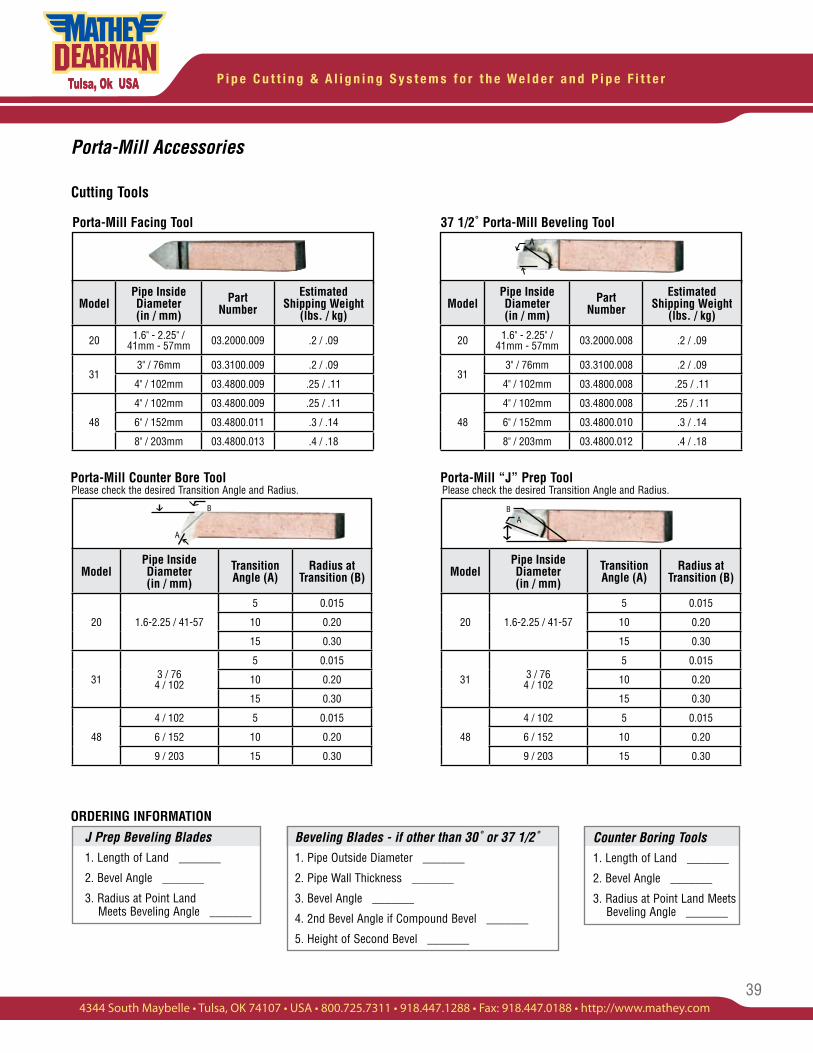
39
P i p e C u t t i n g & A l i g n i n g S y s t e m s f o r t h e W e l d e r a n d P i p e F i t t e r
4344 South Maybelle • Tulsa, OK 74107 • USA • 800.725.7311 • 918.447.1288 • Fax: 918.447.0188 • http://www.mathey.com
Counter Boring Tools1. Length of Land _______
2. Bevel Angle _______
3. Radius at Point Land Meets Beveling Angle _______
J Prep Beveling Blades1. Length of Land _______
2. Bevel Angle _______
3. Radius at Point Land Meets Beveling Angle _______
Beveling Blades - if other than 30˚ or 37 1/2˚1. Pipe Outside Diameter _______
2. Pipe Wall Thickness _______
3. Bevel Angle _______
4. 2nd Bevel Angle if Compound Bevel _______
5. Height of Second Bevel _______
ORDERING INFORMATION
A
BA
Please check the desired Transition Angle and Radius.
A
B
Porta-Mill Accessories
Porta-Mill Facing Tool 37 1/2˚ Porta-Mill Beveling Tool
Porta-Mill Counter Bore Tool Porta-Mill “J” Prep Tool
Cutting Tools
ModelPipe Inside Diameter(in / mm)
Transition Angle (A)
Radius at Transition (B)
20 1.6-2.25 / 41-57
5 0.015
10 0.20
15 0.30
31 3 / 764 / 102
5 0.015
10 0.20
15 0.30
48
4 / 102 5 0.015
6 / 152 10 0.20
9 / 203 15 0.30
ModelPipe Inside Diameter(in / mm)
Part Number
EstimatedShipping Weight
(lbs. / kg)
20 1.6" - 2.25" / 41mm - 57mm 03.2000.008 .2 / .09
313" / 76mm 03.3100.008 .2 / .09
4" / 102mm 03.4800.008 .25 / .11
48
4" / 102mm 03.4800.008 .25 / .11
6" / 152mm 03.4800.010 .3 / .14
8" / 203mm 03.4800.012 .4 / .18
ModelPipe Inside Diameter(in / mm)
Part Number
EstimatedShipping Weight
(lbs. / kg)
20 1.6" - 2.25" / 41mm - 57mm 03.2000.009 .2 / .09
313" / 76mm 03.3100.009 .2 / .09
4" / 102mm 03.4800.009 .25 / .11
48
4" / 102mm 03.4800.009 .25 / .11
6" / 152mm 03.4800.011 .3 / .14
8" / 203mm 03.4800.013 .4 / .18
ModelPipe Inside Diameter(in / mm)
Transition Angle (A)
Radius at Transition (B)
20 1.6-2.25 / 41-57
5 0.015
10 0.20
15 0.30
31 3 / 764 / 102
5 0.015
10 0.20
15 0.30
48
4 / 102 5 0.015
6 / 152 10 0.20
9 / 203 15 0.30
Please check the desired Transition Angle and Radius.
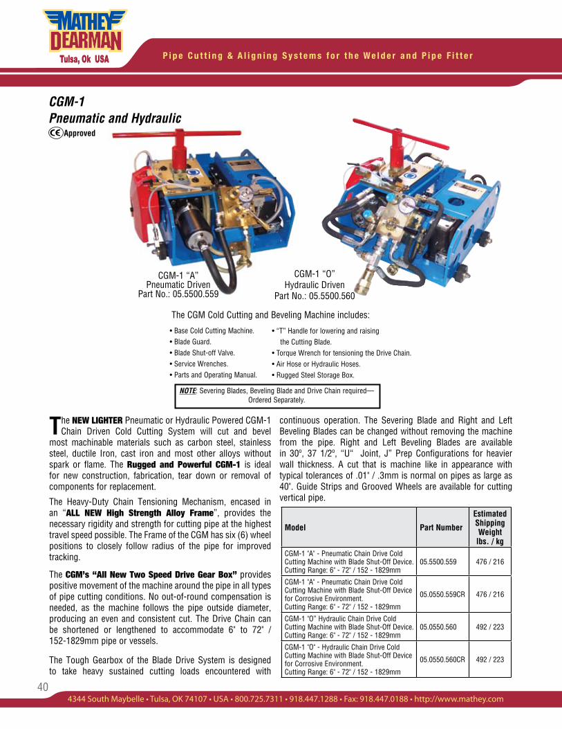
P i p e C u t t i n g & A l i g n i n g S y s t e m s f o r t h e W e l d e r a n d P i p e F i t t e r
40
CGM-1 “A” Pneumatic Driven
Part No.: 05.5500.559
CGM-1 “O” Hydraulic Driven
Part No.: 05.5500.560
CGM-1Pneumatic and Hydraulic
continuous operation. The Severing Blade and Right and Left Beveling Blades can be changed without removing the machine from the pipe. Right and Left Beveling Blades are available in 30º, 37 1/2º, “U“ Joint, J” Prep Configurations for heavier wall thickness. A cut that is machine like in appearance with typical tolerances of .01" / .3mm is normal on pipes as large as 40". Guide Strips and Grooved Wheels are available for cutting vertical pipe.
The CGM Cold Cutting and Beveling Machine includes:
• Base Cold Cutting Machine. • Blade Guard.• Blade Shut-off Valve. • Service Wrenches.• Parts and Operating Manual.
• “T” Handle for lowering and raising the Cutting Blade.• Torque Wrench for tensioning the Drive Chain.• Air Hose or Hydraulic Hoses.• Rugged Steel Storage Box.
Model Part Number
Estimated Shipping Weight lbs. / kg
CGM-1 "A" - Pneumatic Chain Drive Cold Cutting Machine with Blade Shut-Off Device. Cutting Range: 6" - 72" / 152 - 1829mm
05.5500.559 476 / 216
CGM-1 "A" - Pneumatic Chain Drive Cold Cutting Machine with Blade Shut-Off Device for Corrosive Environment. Cutting Range: 6" - 72" / 152 - 1829mm
05.0550.559CR 476 / 216
CGM-1 "O” Hydraulic Chain Drive Cold Cutting Machine with Blade Shut-Off Device. Cutting Range: 6" - 72" / 152 - 1829mm
05.0550.560 492 / 223
CGM-1 "O" - Hydraulic Chain Drive Cold Cutting Machine with Blade Shut-Off Device for Corrosive Environment. Cutting Range: 6" - 72" / 152 - 1829mm
05.0550.560CR 492 / 223
The NEW LIGHTER Pneumatic or Hydraulic Powered CGM-1 Chain Driven Cold Cutting System will cut and bevel
most machinable materials such as carbon steel, stainless steel, ductile Iron, cast iron and most other alloys without spark or flame. The Rugged and Powerful CGM-1 is ideal for new construction, fabrication, tear down or removal of components for replacement.
The Heavy-Duty Chain Tensioning Mechanism, encased in an “ALL NEW High Strength Alloy Frame”, provides the necessary rigidity and strength for cutting pipe at the highest travel speed possible. The Frame of the CGM has six (6) wheel positions to closely follow radius of the pipe for improved tracking.
The CGM’s “All New Two Speed Drive Gear Box” provides positive movement of the machine around the pipe in all types of pipe cutting conditions. No out-of-round compensation is needed, as the machine follows the pipe outside diameter, producing an even and consistent cut. The Drive Chain can be shortened or lengthened to accommodate 6" to 72" / 152-1829mm pipe or vessels.
The Tough Gearbox of the Blade Drive System is designed to take heavy sustained cutting loads encountered with
NOTE: Severing Blades, Beveling Blade and Drive Chain required— Ordered Separately.
Approved
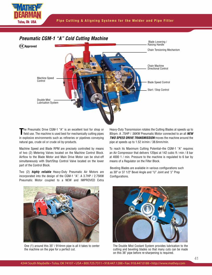
41
P i p e C u t t i n g & A l i g n i n g S y s t e m s f o r t h e W e l d e r a n d P i p e F i t t e r
4344 South Maybelle • Tulsa, OK 74107 • USA • 800.725.7311 • 918.447.1288 • Fax: 918.447.0188 • http://www.mathey.com
The Pneumatic Drive CGM-1 “A” is an excellent tool for shop or field use. The machine is used best for mechanically cutting pipes
in explosive environments such as refineries or pipelines conveying natural gas, crude oil or crude oil by-products.
Machine Speed and Blade RPM are precisely controlled by means of two (2) Metering Valves located on the Machine Control Block. Airflow to the Blade Motor and Main Drive Motor can be shut-off simultaneously with Start/Stop Control Valve located on the lower part of the Control Block.
Two (2) highly reliable Heavy-Duty Pneumatic Air Motors are incorporated into the design of the CGM-1 “A”. A 3.7HP / 2.75KW Pneumatic Motor coupled to a NEW and IMPROVED Extra
Heavy-Duty Transmission rotates the Cutting Blades at speeds up to 80rpm. A .75HP / .56KW Pneumatic Motor connected to an all NEW TWO SPEED DRIVE TRANSMISSION moves the machine around the pipe at speeds up to 1.52 in/min / 38.6mm/min.
To reach its Maximum Cutting Potential–the CGM-1 “A” requires an Air Compressor that delivers 120psi at 142 cubic ft / min / 8 bar at 4000 1 / min. Pressure to the machine is regulated to 6 bar by means of a Regulator on the Filter Block.
Beveling Blades are available in various configurations such as 30º or 37 1/2º Bevel Angle and “U” Joint and “J” Prep Configurations.
Blade Lowering / Raising Handle
Chain Tensioning Mechanism
Chain Machine Directional Control
Blade Speed Control
Start / Stop Control
Machine Speed Control
Double Mist Lubrication System
Pneumatic CGM-1 “A” Cold Cutting Machine
The Double Mist Coolant System provides lubrication to the cutting and beveling blades so that many cuts can be made on this 36" pipe before re-sharpening is required.
One (1) around this 35" / 914mm pipe is all it takes to center the machine on the pipe for a perfect cut.
Approved
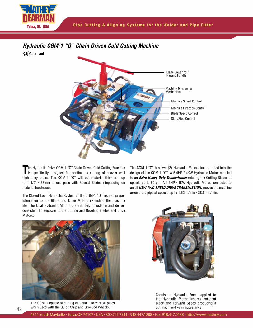
P i p e C u t t i n g & A l i g n i n g S y s t e m s f o r t h e W e l d e r a n d P i p e F i t t e r
42
Hydraulic CGM-1 “O” Chain Driven Cold Cutting Machine
The Hydraulic Drive CGM-1 “O” Chain Driven Cold Cutting Machine is specifically designed for continuous cutting of heavier wall
high alloy pipes. The CGM-1 “O” will cut material thickness up to 1 1/2" / 38mm in one pass with Special Blades (depending on material hardness).
The Closed Loop Hydraulic System of the CGM-1 “O” insures proper lubrication to the Blade and Drive Motors extending the machine life. The Dual Hydraulic Motors are infinitely adjustable and deliver consistent horsepower to the Cutting and Beveling Blades and Drive Motors.
The CGM-1 “O” has two (2) Hydraulic Motors incorporated into the design of the CGM-1 “O”. A 5.4HP / 4KW Hydraulic Motor, coupled to an Extra Heavy-Duty Transmission rotating the Cutting Blades at speeds up to 80rpm. A 1.3HP / 1KW Hydraulic Motor, connected to an all NEW TWO SPEED DRIVE TRANSMISSION, moves the machine around the pipe at speeds up to 1.52 in/min / 38.6mm/min.
Consistent Hydraulic Force, applied to the Hydraulic Motor, insures constant Blade and Forward Speed producing a cut machine-like in appearance.
Machine Tensioning Mechanism
Machine Speed Control
Machine Direction Control
Blade Speed Control
Start/Stop Control
Blade Lowering / Raising Handle
Approved
The CGM is cpable of cutting diagonal and vertical pipes when used with the Guide Strip and Grooved Wheels.
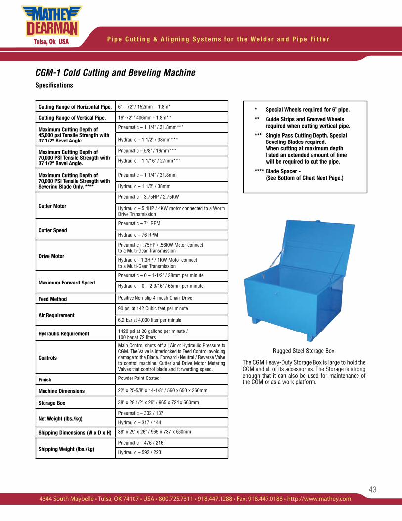
43
P i p e C u t t i n g & A l i g n i n g S y s t e m s f o r t h e W e l d e r a n d P i p e F i t t e r
4344 South Maybelle • Tulsa, OK 74107 • USA • 800.725.7311 • 918.447.1288 • Fax: 918.447.0188 • http://www.mathey.com
CGM-1 Cold Cutting and Beveling MachineSpecifications
Cutting Range of Horizontal Pipe. 6" – 72" / 152mm – 1.8m*
Cutting Range of Vertical Pipe. 16"-72" / 406mm - 1.8m**
Maximum Cutting Depth of 45,000 psi Tensile Strength with 37 1/2º Bevel Angle.
Pneumatic – 1 1/4" / 31.8mm***
Hydraulic – 1 1/2" / 38mm***
Maximum Cutting Depth of 70,000 PSI Tensile Strength with 37 1/2º Bevel Angle.
Pneumatic – 5/8" / 16mm***
Hydraulic – 1 1/16" / 27mm***
Maximum Cutting Depth of 70,000 PSI Tensile Strength with Severing Blade Only. ****
Pneumatic – 1 1/4" / 31.8mm
Hydraulic – 1 1/2" / 38mm
Cutter Motor
Pneumatic – 3.75HP / 2.75KW
Hydraulic – 5.4HP / 4KW motor connected to a Worm Drive Transmission
Cutter SpeedPneumatic – 71 RPM
Hydraulic – 76 RPM
Drive Motor
Pneumatic - .75HP / .56KW Motor connect to a Multi-Gear Transmission
Hydraulic - 1.3HP / 1KW Motor connect to a Multi-Gear Transmission
Maximum Forward SpeedPneumatic – 0 – 1-1/2" / 38mm per minute
Hydraulic – 0 – 2 9/16" / 65mm per minute
Feed Method Positive Non-slip 4-mesh Chain Drive
Air Requirement90 psi at 142 Cubic feet per minute
6.2 bar at 4,000 liter per minute
Hydraulic Requirement 1420 psi at 20 gallons per minute / 100 bar at 72 liters
Controls
Main Control shuts off all Air or Hydraulic Pressure to CGM. The Valve is interlocked to Feed Control avoiding damage to the Blade. Forward / Neutral / Reverse Valve to control machine. Cutter and Drive Motor Metering Valves that control blade and forwarding speed.
Finish Powder Paint Coated
Machine Dimensions 22" x 25-5/8" x 14-1/8" / 560 x 650 x 360mm
Storage Box 38" x 28 1/2" x 26" / 965 x 724 x 660mm
Net Weight (lbs./kg)Pneumatic – 302 / 137
Hydraulic – 317 / 144
Shipping Dimensions (W x D x H) 38" x 29" x 26" / 965 x 737 x 660mm
Shipping Weight (lbs./kg)Pneumatic – 476 / 216
Hydraulic – 592 / 223
* Special Wheels required for 6" pipe.
** Guide Strips and Grooved Wheels required when cutting vertical pipe.
*** Single Pass Cutting Depth. Special Beveling Blades required. When cutting at maximum depth listed an extended amount of time will be required to cut the pipe.
**** Blade Spacer - (See Bottom of Chart Next Page.)
Rugged Steel Storage Box
The CGM Heavy-Duty Storage Box is large to hold the CGM and all of its accessories. The Storage is strong enough that it can also be used for maintenance of the CGM or as a work platform.
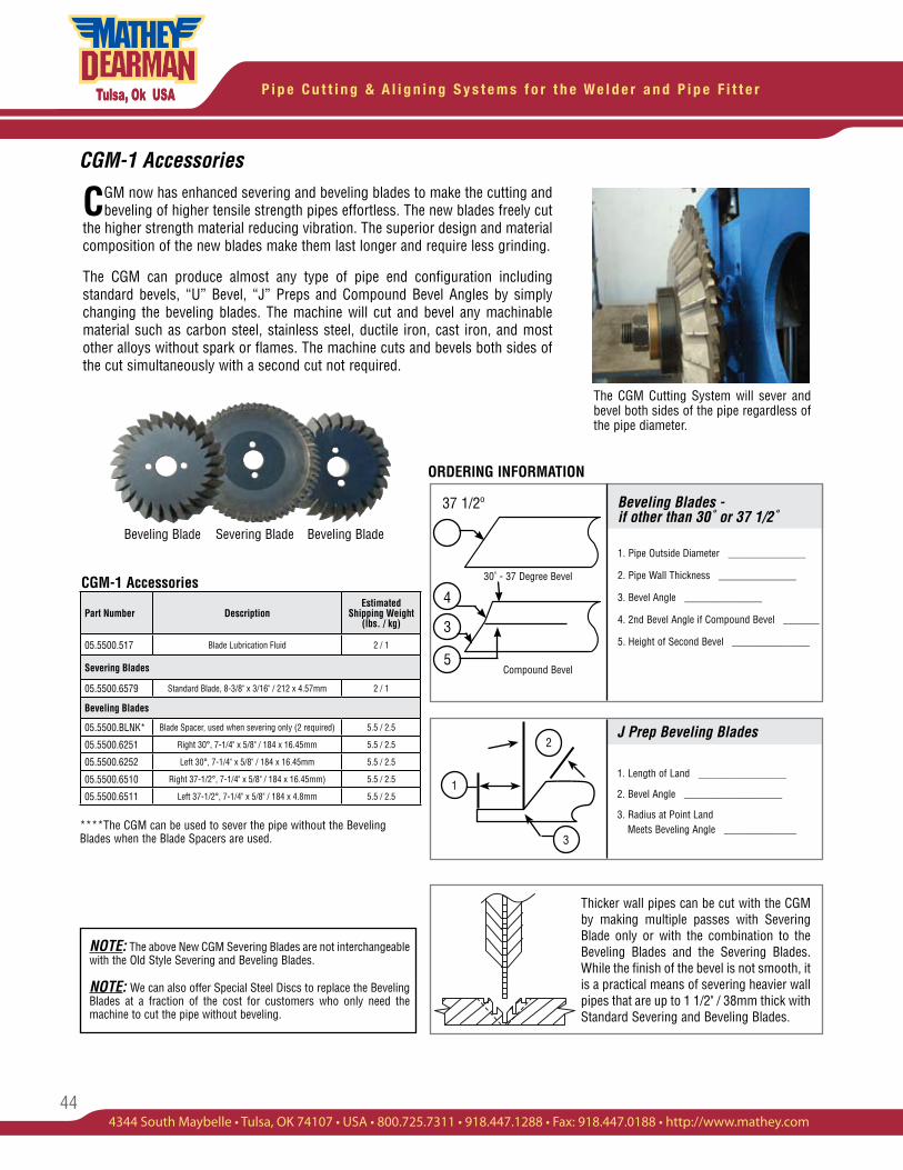
P i p e C u t t i n g & A l i g n i n g S y s t e m s f o r t h e W e l d e r a n d P i p e F i t t e r
44
CGM-1 Accessories
J Prep Beveling Blades
1. Length of Land _________________
2. Bevel Angle ___________________
3. Radius at Point Land Meets Beveling Angle ______________
Beveling Blades - if other than 30˚ or 37 1/2˚
1. Pipe Outside Diameter _______________
2. Pipe Wall Thickness _______________
3. Bevel Angle _______________
4. 2nd Bevel Angle if Compound Bevel _______
5. Height of Second Bevel _______________
CGM now has enhanced severing and beveling blades to make the cutting and beveling of higher tensile strength pipes effortless. The new blades freely cut
the higher strength material reducing vibration. The superior design and material composition of the new blades make them last longer and require less grinding.
The CGM can produce almost any type of pipe end configuration including standard bevels, “U” Bevel, “J” Preps and Compound Bevel Angles by simply changing the beveling blades. The machine will cut and bevel any machinable material such as carbon steel, stainless steel, ductile iron, cast iron, and most other alloys without spark or flames. The machine cuts and bevels both sides of the cut simultaneously with a second cut not required.
CGM-1 Accessories
1
2
3
Part Number DescriptionEstimated
Shipping Weight (lbs. / kg)
05.5500.517 Blade Lubrication Fluid 2 / 1
Severing Blades
05.5500.6579 Standard Blade, 8-3/8" x 3/16" / 212 x 4.57mm 2 / 1
Beveling Blades
05.5500.BLNK* Blade Spacer, used when severing only (2 required) 5.5 / 2.5
05.5500.6251 Right 30°, 7-1/4" x 5/8" / 184 x 16.45mm 5.5 / 2.5
05.5500.6252 Left 30°, 7-1/4" x 5/8" / 184 x 16.45mm 5.5 / 2.5
05.5500.6510 Right 37-1/2°, 7-1/4" x 5/8" / 184 x 16.45mm) 5.5 / 2.5
05.5500.6511 Left 37-1/2°, 7-1/4" x 5/8" / 184 x 4.8mm 5.5 / 2.5
NOTE: The above New CGM Severing Blades are not interchangeable with the Old Style Severing and Beveling Blades.
The CGM Cutting System will sever and bevel both sides of the pipe regardless of the pipe diameter.
Beveling Blade Severing Blade Beveling Blade
Thicker wall pipes can be cut with the CGM by making multiple passes with Severing Blade only or with the combination to the Beveling Blades and the Severing Blades. While the finish of the bevel is not smooth, it is a practical means of severing heavier wall pipes that are up to 1 1/2" / 38mm thick with Standard Severing and Beveling Blades.
ORDERING INFORMATION
****The CGM can be used to sever the pipe without the Beveling Blades when the Blade Spacers are used.
4
3
5
37 1/2º
30˚ - 37 Degree Bevel
Compound Bevel
NOTE: We can also offer Special Steel Discs to replace the Beveling Blades at a fraction of the cost for customers who only need the machine to cut the pipe without beveling.
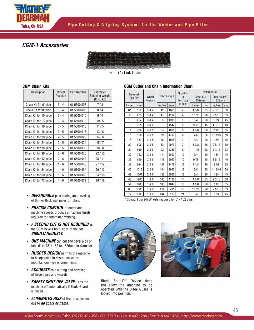
45
P i p e C u t t i n g & A l i g n i n g S y s t e m s f o r t h e W e l d e r a n d P i p e F i t t e r
4344 South Maybelle • Tulsa, OK 74107 • USA • 800.725.7311 • 918.447.1288 • Fax: 918.447.0188 • http://www.mathey.com
CGM-1 Accessories
CGM Chain Kits
Blade Shut-Off Device does not allow the machine to be operated until the Blade Guard is locked into position.
• DEPENDABLE pipe cutting and beveling of thin or thick wall pipes or tubes.
• PRECISE CONTROL of cutter and machine speeds produce a machine finish required for automated welding.
• A SECOND CUT IS NOT REQUIRED as the CGM bevels both sides of the cut SIMULTANEOUSLY.
• ONE MACHINE can cut and bevel pipe or tube 6" to 72" / 152 to 1826mm in diameter.
• RUGGED DESIGN permits the machine to be operated in desert, ocean or mountainous type environments.
• ACCURATE cold cutting and beveling of large pipes and vessels.
• SAFETY SHUT-OFF VALVE turns the machine off automatically if Blade Guard is raised.
• ELIMINATES RISK of fire or explosion due to no spark or flame.
Four (4) Link Chain
CGM Cutter and Chain Information ChartDescription Wheel
PositionPart Number Estimated
Shipping Weight (lbs. / kg)
Chain Kit for 6" pipe 3 - 4 01.5500.006 7 / 3
Chain Kit for 8" pipe 3 - 4 01.5500.008 8 / 4
Chain Kit for 10" pipe 3 - 4 01.5500.010 9 / 4
Chain Kit for "12 pipe 3 - 4 01.5500.012 10 / 5
Chain Kit for 16" pipe 3 - 5 01.5500.016 11 / 5
Chain Kit for 18" pipe 3 - 5 01.5500.018 13 / 6
Chain Kit for 20" pipe 2 - 5 01.5500.020 14 / 6
Chain Kit for 24" pipe 2 - 5 01.5500.024 15 / 7
Chain Kit for 30" pipe 2 - 5 01.5500.030 18 / 8
Chain Kit for 36" pipe 2 - 6 01.5500.036 22 / 10
Chain Kit for 42" pipe 2 - 6 01.5500.042 25 / 11
Chain Kit for 48" pipe 1 - 6 01.5500.048 27 / 12
Chain Kit for 54" pipe 1 - 6 01.5500.054 29 / 13
Chain Kit for 60" pipe 1 - 6 01.5500.060 34 / 16
Chain Kit for 72" pipe 1 - 6 01.5500.072 39 / 18
Nominal Pipe Size Wheel
PositionChain Length
Quantity to
Purchase in Feet
Depth of Cut
Cutter 6" / 152mm
Cutter 8 3/8" / 212mm
Inches mm Inches mm Inches mm Inches mm
6* 152 3 & 4 42 1065 4 1 3/8 35 2 5/16 60
8 203 3 & 4 47 1192 4 1 1/16 28 2 1/16 53
10 254 3 & 4 55 1395 5 3/4 20 1 3/4 45
12 305 3 & 4 61 1547 6 9/16 15 1 9/16 40
14 356 3 & 5 63 1598 6 1 1/8 30 2 1/8 55
16 408 3 & 5 69 1750 6 7/8 25 1 15/16 50
18 457 3 & 5 76 1918 7 3/4 20 1 3/4 45
20 508 2 & 5 82 2070 7 1 3/8 35 2 5/16 60
24 610 2 & 5 92 2335 8 1 1/16 28 2 1/16 53
30 762 2 & 5 114 2892 10 3/4 20 1 3/4 45
32 810 2 & 5 116 2940 10 9/16 15 1 9/16 40
36 914 2 & 6 137 3476 12 1 1/8 30 2 1/8 55
40 1016 2 & 6 144 3650 12 7/8 25 1 15/16 50
42 1067 2 & 6 156 3950 13 3/4 20 1 3/4 45
48 1200 1 & 6 165 4180 14 1 3/8 35 2 5/16 60
54 1400 1 & 6 183 4644 16 1 1/8 30 2 1/8 55
60 1500 1 & 6 214 5431 18 1 1/16 28 2 1/16 53
72 1800 1 & 6 244 6193 21 3/4 20 1 3/4 45
* Special Four (4) Wheels required for 6" / 152 pipe.
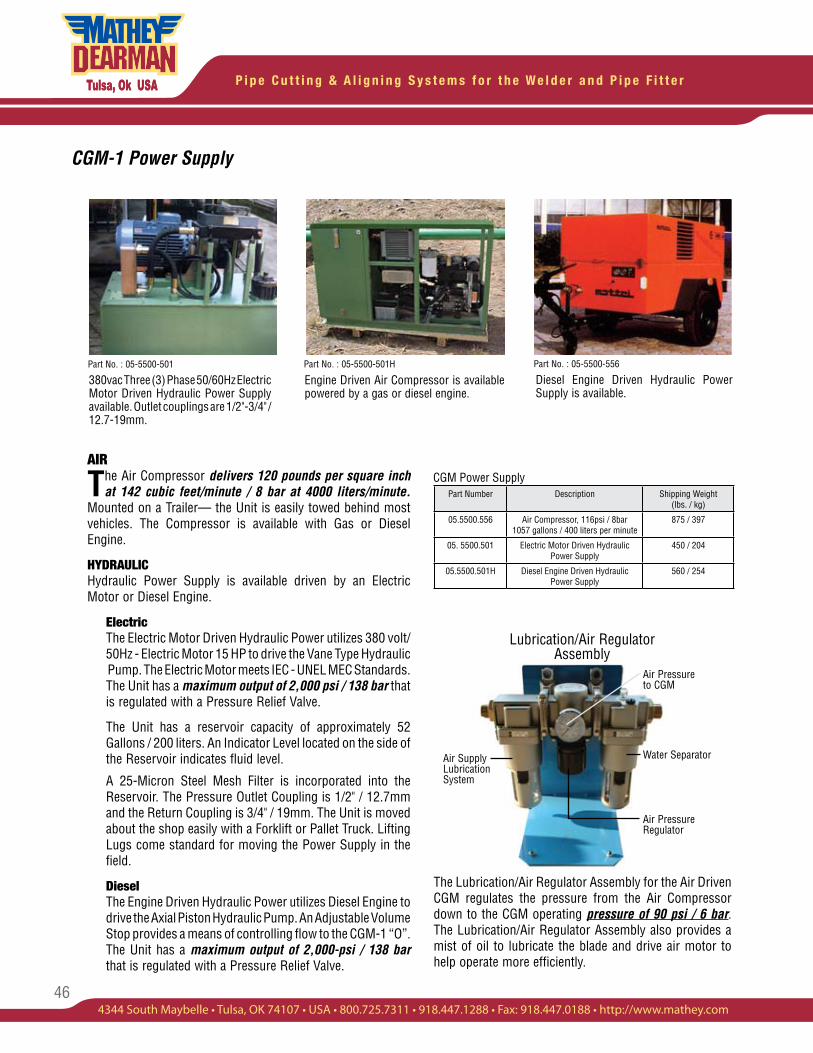
P i p e C u t t i n g & A l i g n i n g S y s t e m s f o r t h e W e l d e r a n d P i p e F i t t e r
46
CGM-1 Power Supply
380vac Three (3) Phase 50/60Hz Electric Motor Driven Hydraulic Power Supply available. Outlet couplings are 1/2"-3/4" / 12.7-19mm.
Diesel Engine Driven Hydraulic Power Supply is available.
Engine Driven Air Compressor is available powered by a gas or diesel engine.
AIR
The Air Compressor delivers 120 pounds per square inch at 142 cubic feet/minute / 8 bar at 4000 liters/minute.
Mounted on a Trailer— the Unit is easily towed behind most vehicles. The Compressor is available with Gas or Diesel Engine.
HYDRAULICHydraulic Power Supply is available driven by an Electric Motor or Diesel Engine.
Electric The Electric Motor Driven Hydraulic Power utilizes 380 volt/ 50Hz - Electric Motor 15 HP to drive the Vane Type Hydraulic Pump. The Electric Motor meets IEC - UNEL MEC Standards. The Unit has a maximum output of 2,000 psi / 138 bar that is regulated with a Pressure Relief Valve.
The Unit has a reservoir capacity of approximately 52 Gallons / 200 liters. An Indicator Level located on the side of the Reservoir indicates fluid level.
A 25-Micron Steel Mesh Filter is incorporated into the Reservoir. The Pressure Outlet Coupling is 1/2" / 12.7mm and the Return Coupling is 3/4" / 19mm. The Unit is moved about the shop easily with a Forklift or Pallet Truck. Lifting Lugs come standard for moving the Power Supply in the field.
Diesel The Engine Driven Hydraulic Power utilizes Diesel Engine to drive the Axial Piston Hydraulic Pump. An Adjustable Volume Stop provides a means of controlling flow to the CGM-1 “O”. The Unit has a maximum output of 2,000-psi / 138 bar that is regulated with a Pressure Relief Valve.
Part No. : 05-5500-556Part No. : 05-5500-501HPart No. : 05-5500-501
The Lubrication/Air Regulator Assembly for the Air Driven CGM regulates the pressure from the Air Compressor down to the CGM operating pressure of 90 psi / 6 bar. The Lubrication/Air Regulator Assembly also provides a mist of oil to lubricate the blade and drive air motor to help operate more efficiently.
Part Number Description Shipping Weight(lbs. / kg)
05.5500.556 Air Compressor, 116psi / 8bar 1057 gallons / 400 liters per minute
875 / 397
05. 5500.501 Electric Motor Driven Hydraulic Power Supply
450 / 204
05.5500.501H Diesel Engine Driven Hydraulic Power Supply
560 / 254
CGM Power Supply
Air Pressure to CGM
Water Separator
Air Pressure Regulator
Air Supply Lubrication System
Lubrication/Air Regulator Assembly
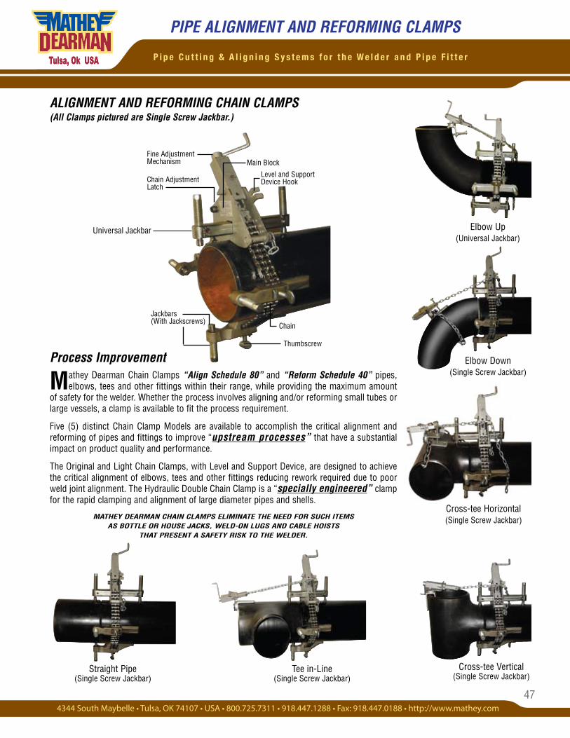
47
P i p e C u t t i n g & A l i g n i n g S y s t e m s f o r t h e W e l d e r a n d P i p e F i t t e r
ALIGNMENT AND REFORMING CHAIN CLAMPS (All Clamps pictured are Single Screw Jackbar.)
Tee in-Line (Single Screw Jackbar)
Straight Pipe (Single Screw Jackbar)
Thumbscrew
Main Block
Level and Support Device Hook
Jackbars (With Jackscrews)
PIPE ALIGNMENT AND REFORMING CLAMPS
Process Improvement
Mathey Dearman Chain Clamps “Align Schedule 80” and “Reform Schedule 40” pipes, elbows, tees and other fittings within their range, while providing the maximum amount
of safety for the welder. Whether the process involves aligning and/or reforming small tubes or large vessels, a clamp is available to fit the process requirement.
Five (5) distinct Chain Clamp Models are available to accomplish the critical alignment and reforming of pipes and fittings to improve “upstream processes” that have a substantial impact on product quality and performance.
The Original and Light Chain Clamps, with Level and Support Device, are designed to achieve the critical alignment of elbows, tees and other fittings reducing rework required due to poor weld joint alignment. The Hydraulic Double Chain Clamp is a “specially engineered” clamp for the rapid clamping and alignment of large diameter pipes and shells.
MATHEY DEARMAN CHAIN CLAMPS ELIMINATE THE NEED FOR SUCH ITEMS AS BOTTLE OR HOUSE JACKS, WELD-ON LUGS AND CABLE HOISTS
THAT PRESENT A SAFETY RISK TO THE WELDER.
Elbow Up (Universal Jackbar)
Elbow Down (Single Screw Jackbar)
Cross-tee Vertical (Single Screw Jackbar)
Cross-tee Horizontal (Single Screw Jackbar)
Fine Adjustment Mechanism
Chain Adjustment Latch
Chain
Universal Jackbar
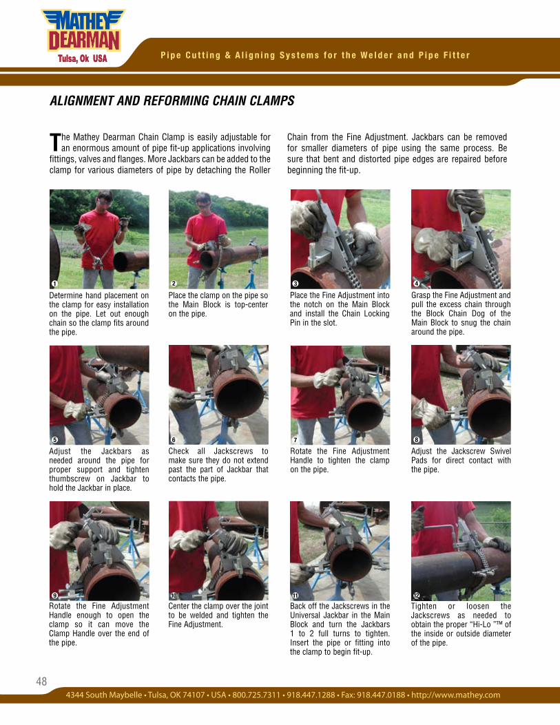
48
P i p e C u t t i n g & A l i g n i n g S y s t e m s f o r t h e W e l d e r a n d P i p e F i t t e r
Determine hand placement on the clamp for easy installation on the pipe. Let out enough chain so the clamp fits around the pipe.
Place the clamp on the pipe so the Main Block is top-center on the pipe.
Grasp the Fine Adjustment and pull the excess chain through the Block Chain Dog of the Main Block to snug the chain around the pipe.
Place the Fine Adjustment into the notch on the Main Block and install the Chain Locking Pin in the slot.
Adjust the Jackbars as needed around the pipe for proper support and tighten thumbscrew on Jackbar to hold the Jackbar in place.
Check all Jackscrews to make sure they do not extend past the part of Jackbar that contacts the pipe.
The Mathey Dearman Chain Clamp is easily adjustable for an enormous amount of pipe fit-up applications involving
fittings, valves and flanges. More Jackbars can be added to the clamp for various diameters of pipe by detaching the Roller
ALIGNMENT AND REFORMING CHAIN CLAMPS
Rotate the Fine Adjustment Handle to tighten the clamp on the pipe.
Adjust the Jackscrew Swivel Pads for direct contact with the pipe.
Rotate the Fine Adjustment Handle enough to open the clamp so it can move the Clamp Handle over the end of the pipe.
Center the clamp over the joint to be welded and tighten the Fine Adjustment.
Back off the Jackscrews in the Universal Jackbar in the Main Block and turn the Jackbars 1 to 2 full turns to tighten. Insert the pipe or fitting into the clamp to begin fit-up.
Tighten or loosen the Jackscrews as needed to obtain the proper “Hi-Lo ”™ of the inside or outside diameter of the pipe.
1 2 3 4
5 6 7 8
9 10 11 12
Chain from the Fine Adjustment. Jackbars can be removed for smaller diameters of pipe using the same process. Be sure that bent and distorted pipe edges are repaired before beginning the fit-up.
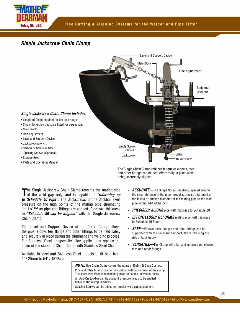
49
P i p e C u t t i n g & A l i g n i n g S y s t e m s f o r t h e W e l d e r a n d P i p e F i t t e r
• ACCURATE—The Single Screw Jackbars, spaced around the circumference of the pipe, provides precise alignment of the inside or outside diameter of the mating pipe to the main pipe within 1/64 of an inch.
• PRECISELY ALIGNS pipe wall thickness to Schedule 80.
• EFFORTLESSLY REFORMS mating pipe wall thickness to Schedule 40 Pipe.
• SAFE—Elbows, tees, flanges and other fittings can be supported with the Level and Support Device reducing the risk of back injury.
• VERSATILE—The Clamp will align and reform pipe, elbows, tees and other fittings.
Single Jackscrew Chain Clamp
The Single Chain Clamp reduces fatigue as elbows, tees and other fittings can be held effortlessly in place while being accurately aligned.
The Single Jackscrew Chain Clamp reforms the mating side of the weld gap only, and is capable of “reforming up
to Schedule 40 Pipe”. The Jackscrews of the Jackbar exert pressure on the high points of the mating pipe eliminating “Hi-Lo”™ as pipe and fittings are aligned. Pipe wall thickness to “Schedule 80 can be aligned” with the Single Jackscrew Chain Clamp.
The Level and Support Device of the Chain Clamp allows the pipe, elbow, tee, flange and other fittings to be held safely and securely in place during the alignment and welding process. For Stainless Steel or specialty alloy applications replace the chain of the standard Chain Clamp with Stainless Steel Chain.
Available in steel and Stainless Steel models to fit pipe from 1" / 25mm to 54" / 1372mm.
Single Jackscrew Chain Clamp includes:• Length of Chain required for the pipe range.• Single Jackscrew Jackbars listed for pipe range.• Main Block. • Fine Adjustment.• Level and Support Device. • Jackscrew Wrench. • Carbon or Stainless Steel Spacing Screws (Optional). • Storage Box. • Parts and Operating Manual.
Single Screw Jackbar
Jackscrew Chain Thumbscrew
Main Block
Level and Support Device
Universal Jackbar
Fine Adjustment
NOTE: One Chain Clamp covers the range of Eight (8) Cage Clamps.Pipe and other fittings can be fully welded without removal of the clamp. The Jackscrew Pads independently pivot to handle uneven surfaces.An Add-On Jackbar can be added if pressure needs to be applied between the Clamp Jackbars.Spacing Screws can be added for precise weld gap adjustment.
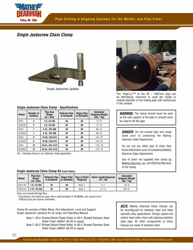
50
P i p e C u t t i n g & A l i g n i n g S y s t e m s f o r t h e W e l d e r a n d P i p e F i t t e r
Single Jackscrew Chain Clamp
Clamp Kit consists of Main Block, Fine Adjustment, Level and Support, Single Jackscrew Jackbars for its range, and Operating Manual.
Note 1. 40-2: Riveted Nickle Plated Roller or 40-2: Riveted Stainless Steel Roller Chain (ANSI#: 40-2R or equal) Note 2. 60-2: Riveted Nickle Plated Roller or 60-2: Riveted Stainless Steel Roller Chain (ANSI#: 60-2R or equal)
Single Jackscrew Chain Clamp - Specifications
Single Jackscrew Chain Clamp Kit (Less Chain)
Single Jackscrew JackbarThe “High-Lo”™ of the 42" / 1067mm pipe can be effortlessly reformed to meet the inside or outside diameter of the mating pipe with Jackscrews in the Jackbar.
SS - Indicates Clamp is for Stainless Steel application.
DANGER: Do not exceed pipe size range listed prior to contacting the Mathey Dearman Sales Department.
Do not use any other type of chain than those listed below prior to contacting Mathey Dearman Sales Department.
Use of chain not supplied with clamp by Mathey Dearman, Inc. will VOID the Warranty of the clamp.
Model Number of Jackbars
Pipe Size Range
(in / mm)Reforms Pipe to Schedule
Aligns Pipe to Schedule
Estimated Shipping Weight
(lbs. / kg)
D231 3 1-8 / 25-203 40 80 21 / 9
D231SS 3 1-8 / 25-203 40 80 21 / 9
D232 7 4-16 / 102-406 40 80 68 / 31
D232SS 7 4-16 / 102-406 40 80 68 / 31
D233 9 10-36 / 254-914 40 80 144 / 67
D233SS 9 10-36 / 254-914 40 80 144 / 67
D234 13 10-54 / 254-1372 40 80 170 / 79
D234SS 13 10-54 / 254-1372 40 80 170 / 79
ModelPipe Size
Range (in / mm)
Reforms Pipe to Schedule
Aligns Pipe to Schedule
Type of Chain Required
Chain Length Required (Ft. / M)
Estimated Shipping Weight
(lbs. / kg)
D231-KIT 1-8 / 25-203 40 80 Note: 1 3 / 1 19 / 9
D232-KIT 4-16 / 25-203 40 80 Note: 2 5 / 1.5 59 / 27
Does not include Storage Box. * Calculations are based on pipe with a yield strength of 45,000lbs. per square inch / 3168 kg force per square centimeter.
NOTE: Mathey Dearman Chain Clamps can be reconfigured for stainless steel and other specialty alloy applications. Simply replace the carbon steel roller chain with aligning stainless steel pipe. All other components of Chain Clamps are made of stainless steel.
WARNING: The clamp should never be used as the sole support of the pipe or should never be used to lift the pipe.
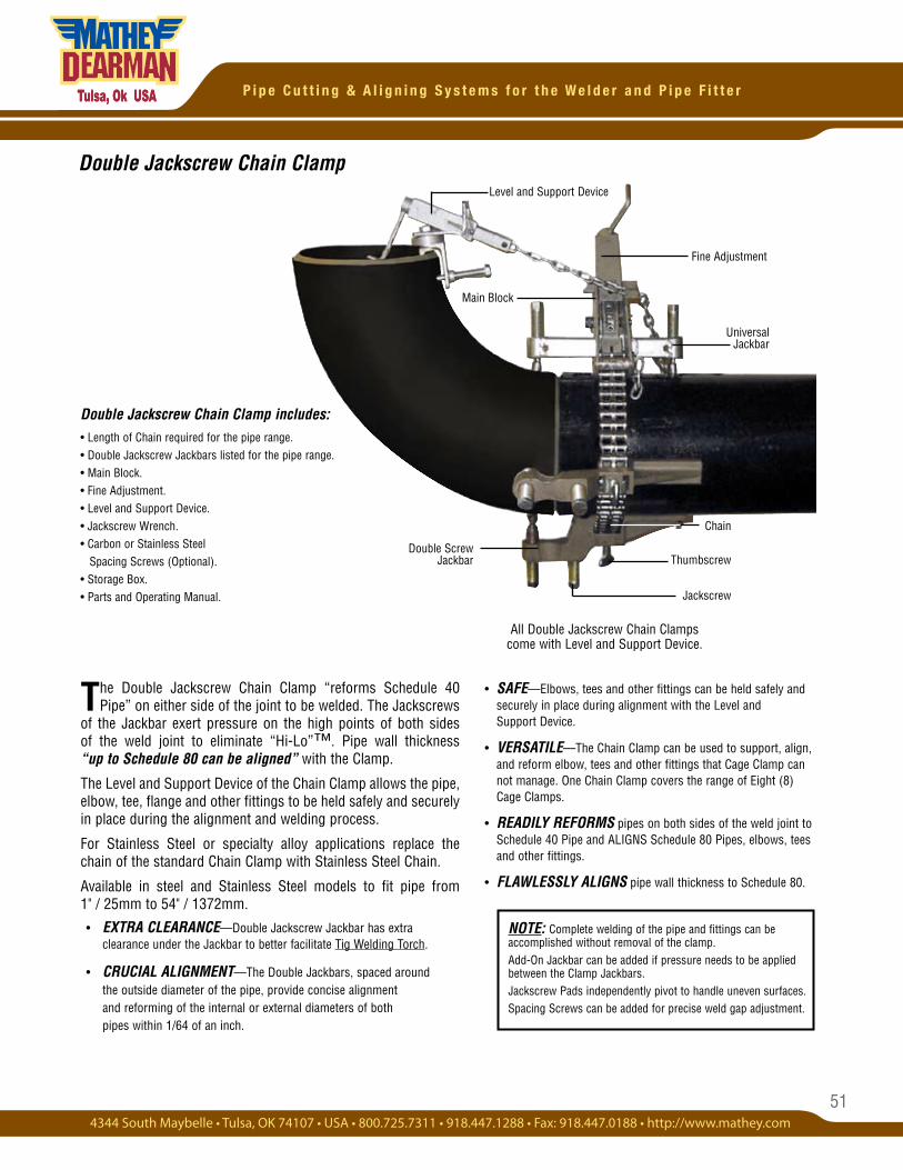
51
P i p e C u t t i n g & A l i g n i n g S y s t e m s f o r t h e W e l d e r a n d P i p e F i t t e r
• SAFE—Elbows, tees and other fittings can be held safely and securely in place during alignment with the Level and Support Device.
• VERSATILE—The Chain Clamp can be used to support, align, and reform elbow, tees and other fittings that Cage Clamp can not manage. One Chain Clamp covers the range of Eight (8) Cage Clamps.
• READILY REFORMS pipes on both sides of the weld joint to Schedule 40 Pipe and ALIGNS Schedule 80 Pipes, elbows, tees and other fittings.
• FLAWLESSLY ALIGNS pipe wall thickness to Schedule 80.
The Double Jackscrew Chain Clamp “reforms Schedule 40 Pipe” on either side of the joint to be welded. The Jackscrews
of the Jackbar exert pressure on the high points of both sides of the weld joint to eliminate “Hi-Lo”™. Pipe wall thickness “up to Schedule 80 can be aligned” with the Clamp.
The Level and Support Device of the Chain Clamp allows the pipe, elbow, tee, flange and other fittings to be held safely and securely in place during the alignment and welding process.
For Stainless Steel or specialty alloy applications replace the chain of the standard Chain Clamp with Stainless Steel Chain.
Available in steel and Stainless Steel models to fit pipe from 1" / 25mm to 54" / 1372mm.
• EXTRA CLEARANCE—Double Jackscrew Jackbar has extra clearance under the Jackbar to better facilitate Tig Welding Torch.
• CRUCIAL ALIGNMENT—The Double Jackbars, spaced around the outside diameter of the pipe, provide concise alignment and reforming of the internal or external diameters of both pipes within 1/64 of an inch.
Double Jackscrew Chain Clamp includes:• Length of Chain required for the pipe range.• Double Jackscrew Jackbars listed for the pipe range.• Main Block. • Fine Adjustment.• Level and Support Device. • Jackscrew Wrench. • Carbon or Stainless Steel Spacing Screws (Optional).• Storage Box. • Parts and Operating Manual.
Double Screw Jackbar
Universal Jackbar
Main Block
Level and Support Device
Fine Adjustment
Chain
Thumbscrew
Jackscrew
All Double Jackscrew Chain Clamps come with Level and Support Device.
Double Jackscrew Chain Clamp
NOTE: Complete welding of the pipe and fittings can be accomplished without removal of the clamp.Add-On Jackbar can be added if pressure needs to be applied between the Clamp Jackbars.Jackscrew Pads independently pivot to handle uneven surfaces.Spacing Screws can be added for precise weld gap adjustment.
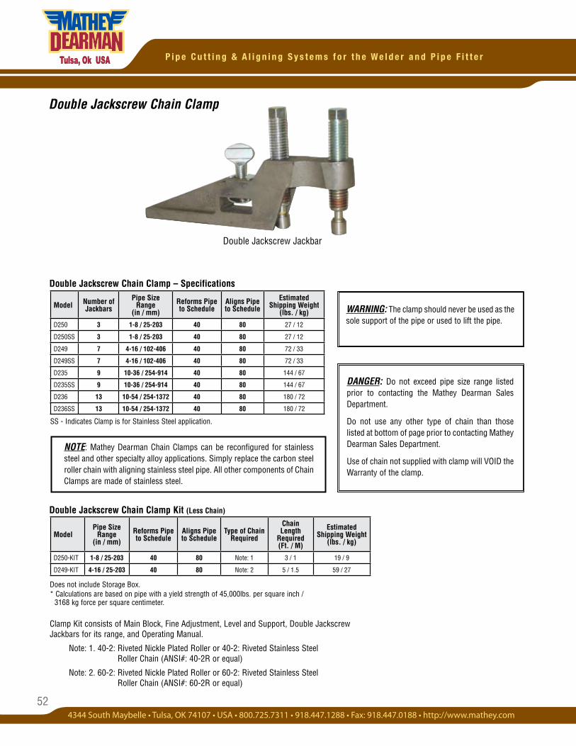
52
P i p e C u t t i n g & A l i g n i n g S y s t e m s f o r t h e W e l d e r a n d P i p e F i t t e r
Double Jackscrew Jackbar
SS - Indicates Clamp is for Stainless Steel application.
Double Jackscrew Chain Clamp – Specifications
Double Jackscrew Chain Clamp
Does not include Storage Box. * Calculations are based on pipe with a yield strength of 45,000lbs. per square inch / 3168 kg force per square centimeter.
Clamp Kit consists of Main Block, Fine Adjustment, Level and Support, Double Jackscrew Jackbars for its range, and Operating Manual.
Note: 1. 40-2: Riveted Nickle Plated Roller or 40-2: Riveted Stainless Steel Roller Chain (ANSI#: 40-2R or equal)
Note: 2. 60-2: Riveted Nickle Plated Roller or 60-2: Riveted Stainless Steel Roller Chain (ANSI#: 60-2R or equal)
Double Jackscrew Chain Clamp Kit (Less Chain)
DANGER: Do not exceed pipe size range listed prior to contacting the Mathey Dearman Sales Department.
Do not use any other type of chain than those listed at bottom of page prior to contacting Mathey Dearman Sales Department.
Use of chain not supplied with clamp will VOID the Warranty of the clamp.
Model Number of Jackbars
Pipe Size Range
(in / mm)Reforms Pipe to Schedule
Aligns Pipe to Schedule
Estimated Shipping Weight
(lbs. / kg)
D250 3 1-8 / 25-203 40 80 27 / 12
D250SS 3 1-8 / 25-203 40 80 27 / 12
D249 7 4-16 / 102-406 40 80 72 / 33
D249SS 7 4-16 / 102-406 40 80 72 / 33
D235 9 10-36 / 254-914 40 80 144 / 67
D235SS 9 10-36 / 254-914 40 80 144 / 67
D236 13 10-54 / 254-1372 40 80 180 / 72
D236SS 13 10-54 / 254-1372 40 80 180 / 72
ModelPipe Size
Range (in / mm)
Reforms Pipe to Schedule
Aligns Pipe to Schedule
Type of Chain Required
Chain Length
Required (Ft. / M)
Estimated Shipping Weight
(lbs. / kg)
D250-KIT 1-8 / 25-203 40 80 Note: 1 3 / 1 19 / 9
D249-KIT 4-16 / 25-203 40 80 Note: 2 5 / 1.5 59 / 27
NOTE: Mathey Dearman Chain Clamps can be reconfigured for stainless steel and other specialty alloy applications. Simply replace the carbon steel roller chain with aligning stainless steel pipe. All other components of Chain Clamps are made of stainless steel.
WARNING: The clamp should never be used as the sole support of the pipe or used to lift the pipe.
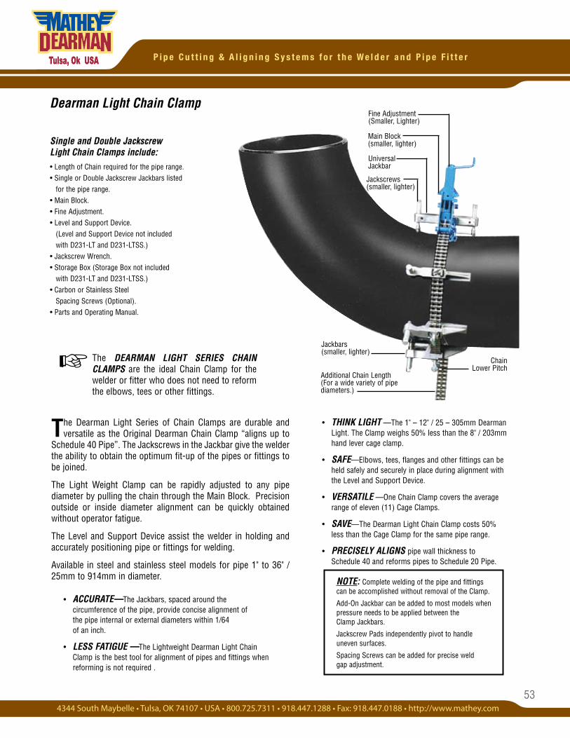
53
P i p e C u t t i n g & A l i g n i n g S y s t e m s f o r t h e W e l d e r a n d P i p e F i t t e r
• THINK LIGHT —The 1" – 12" / 25 – 305mm Dearman Light. The Clamp weighs 50% less than the 8" / 203mm hand lever cage clamp.
• SAFE—Elbows, tees, flanges and other fittings can be held safely and securely in place during alignment with the Level and Support Device.
• VERSATILE —One Chain Clamp covers the average range of eleven (11) Cage Clamps.
• SAVE—The Dearman Light Chain Clamp costs 50% less than the Cage Clamp for the same pipe range.
• PRECISELY ALIGNS pipe wall thickness to Schedule 40 and reforms pipes to Schedule 20 Pipe.
Fine Adjustment (Smaller, Lighter)
Main Block (smaller, lighter)
Jackbars (smaller, lighter)
Chain Lower Pitch
Additional Chain Length (For a wide variety of pipe diameters.)
Jackscrews (smaller, lighter)
Universal Jackbar
The Dearman Light Series of Chain Clamps are durable and versatile as the Original Dearman Chain Clamp “aligns up to
Schedule 40 Pipe”. The Jackscrews in the Jackbar give the welder the ability to obtain the optimum fit-up of the pipes or fittings to be joined.
The Light Weight Clamp can be rapidly adjusted to any pipe diameter by pulling the chain through the Main Block. Precision outside or inside diameter alignment can be quickly obtained without operator fatigue.
The Level and Support Device assist the welder in holding and accurately positioning pipe or fittings for welding.
Available in steel and stainless steel models for pipe 1" to 36" / 25mm to 914mm in diameter.
• ACCURATE—The Jackbars, spaced around the circumference of the pipe, provide concise alignment of the pipe internal or external diameters within 1/64 of an inch.
• LESS FATIGUE —The Lightweight Dearman Light Chain Clamp is the best tool for alignment of pipes and fittings when reforming is not required .
The DEARMAN LIGHT SERIES CHAIN CLAMPS are the ideal Chain Clamp for the welder or fitter who does not need to reform the elbows, tees or other fittings.
Single and Double Jackscrew Light Chain Clamps include:• Length of Chain required for the pipe range.• Single or Double Jackscrew Jackbars listed for the pipe range.• Main Block. • Fine Adjustment.• Level and Support Device. (Level and Support Device not included with D231-LT and D231-LTSS.) • Jackscrew Wrench.• Storage Box (Storage Box not included with D231-LT and D231-LTSS.)• Carbon or Stainless Steel Spacing Screws (Optional).• Parts and Operating Manual.
Dearman Light Chain Clamp
☞
NOTE: Complete welding of the pipe and fittings can be accomplished without removal of the Clamp.
Add-On Jackbar can be added to most models when pressure needs to be applied between the Clamp Jackbars.
Jackscrew Pads independently pivot to handle uneven surfaces.
Spacing Screws can be added for precise weld gap adjustment.
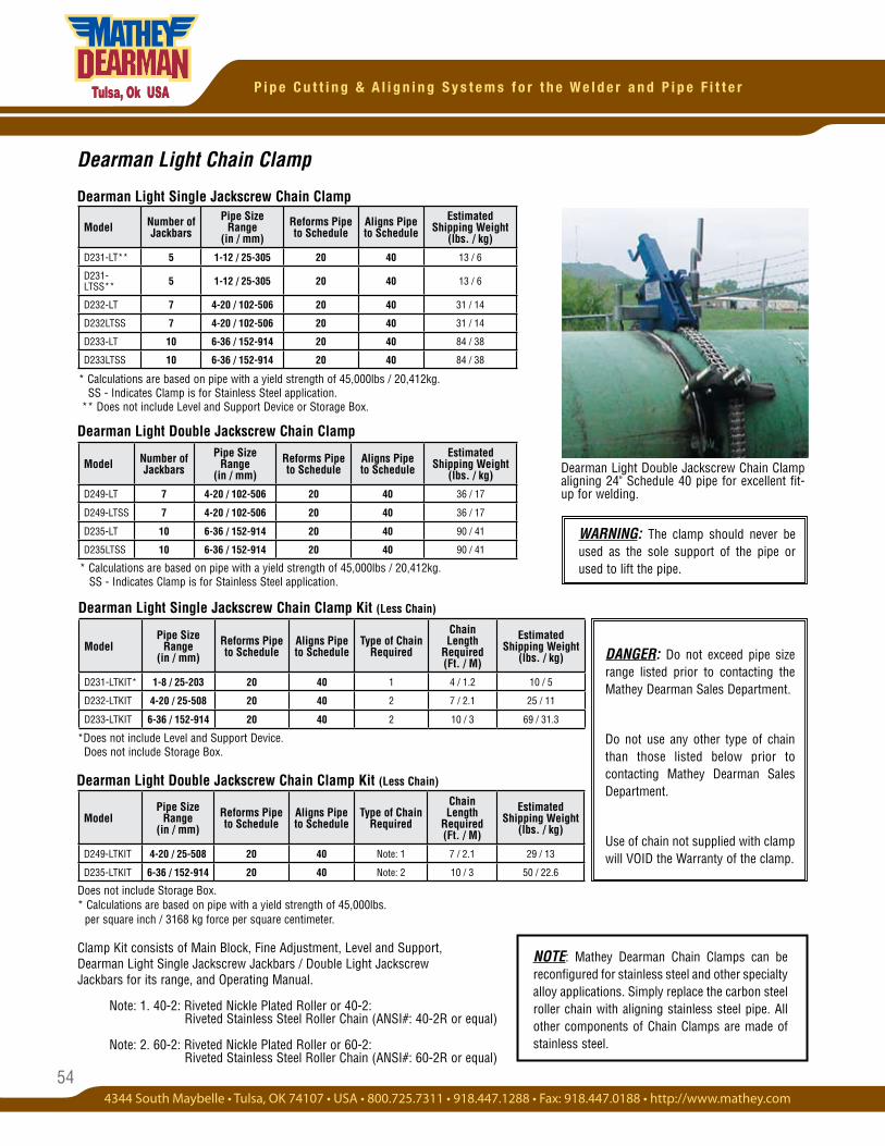
54
P i p e C u t t i n g & A l i g n i n g S y s t e m s f o r t h e W e l d e r a n d P i p e F i t t e r
Dearman Light Single Jackscrew Chain Clamp
* Calculations are based on pipe with a yield strength of 45,000lbs / 20,412kg. SS - Indicates Clamp is for Stainless Steel application.
* Calculations are based on pipe with a yield strength of 45,000lbs / 20,412kg. SS - Indicates Clamp is for Stainless Steel application. ** Does not include Level and Support Device or Storage Box.
Dearman Light Double Jackscrew Chain Clamp
Dearman Light Single Jackscrew Chain Clamp Kit (Less Chain)
Dearman Light Chain Clamp
Dearman Light Double Jackscrew Chain Clamp aligning 24" Schedule 40 pipe for excellent fit-up for welding.
Dearman Light Double Jackscrew Chain Clamp Kit (Less Chain)
DANGER: Do not exceed pipe size range listed prior to contacting the Mathey Dearman Sales Department.
Do not use any other type of chain than those listed below prior to contacting Mathey Dearman Sales Department.
Use of chain not supplied with clamp will VOID the Warranty of the clamp.
NOTE: Mathey Dearman Chain Clamps can be reconfigured for stainless steel and other specialty alloy applications. Simply replace the carbon steel roller chain with aligning stainless steel pipe. All other components of Chain Clamps are made of stainless steel.
Model Number of Jackbars
Pipe Size Range
(in / mm)Reforms Pipe to Schedule
Aligns Pipe to Schedule
Estimated Shipping Weight
(lbs. / kg)
D231-LT** 5 1-12 / 25-305 20 40 13 / 6
D231-LTSS** 5 1-12 / 25-305 20 40 13 / 6
D232-LT 7 4-20 / 102-506 20 40 31 / 14
D232LTSS 7 4-20 / 102-506 20 40 31 / 14
D233-LT 10 6-36 / 152-914 20 40 84 / 38
D233LTSS 10 6-36 / 152-914 20 40 84 / 38
ModelPipe Size
Range (in / mm)
Reforms Pipe to Schedule
Aligns Pipe to Schedule
Type of Chain Required
Chain Length
Required (Ft. / M)
Estimated Shipping Weight
(lbs. / kg)
D231-LTKIT* 1-8 / 25-203 20 40 1 4 / 1.2 10 / 5
D232-LTKIT 4-20 / 25-508 20 40 2 7 / 2.1 25 / 11
D233-LTKIT 6-36 / 152-914 20 40 2 10 / 3 69 / 31.3
Model Number of Jackbars
Pipe Size Range
(in / mm)Reforms Pipe to Schedule
Aligns Pipe to Schedule
Estimated Shipping Weight
(lbs. / kg)
D249-LT 7 4-20 / 102-506 20 40 36 / 17
D249-LTSS 7 4-20 / 102-506 20 40 36 / 17
D235-LT 10 6-36 / 152-914 20 40 90 / 41
D235LTSS 10 6-36 / 152-914 20 40 90 / 41
ModelPipe Size
Range (in / mm)
Reforms Pipe to Schedule
Aligns Pipe to Schedule
Type of Chain Required
Chain Length
Required (Ft. / M)
Estimated Shipping Weight
(lbs. / kg)
D249-LTKIT 4-20 / 25-508 20 40 Note: 1 7 / 2.1 29 / 13
D235-LTKIT 6-36 / 152-914 20 40 Note: 2 10 / 3 50 / 22.6
WARNING: The clamp should never be used as the sole support of the pipe or used to lift the pipe.
*Does not include Level and Support Device. Does not include Storage Box.
Does not include Storage Box. * Calculations are based on pipe with a yield strength of 45,000lbs. per square inch / 3168 kg force per square centimeter.
Clamp Kit consists of Main Block, Fine Adjustment, Level and Support, Dearman Light Single Jackscrew Jackbars / Double Light Jackscrew Jackbars for its range, and Operating Manual.
Note: 1. 40-2: Riveted Nickle Plated Roller or 40-2: Riveted Stainless Steel Roller Chain (ANSI#: 40-2R or equal)
Note: 2. 60-2: Riveted Nickle Plated Roller or 60-2: Riveted Stainless Steel Roller Chain (ANSI#: 60-2R or equal)
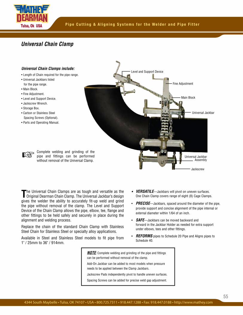
55
P i p e C u t t i n g & A l i g n i n g S y s t e m s f o r t h e W e l d e r a n d P i p e F i t t e r
Complete welding and grinding of the pipe and fittings can be performed without removal of the Universal Clamp.
The Universal Chain Clamps are as tough and versatile as the Original Dearman Chain Clamp. The Universal Jackbar’s design
gives the welder the ability to accurately fit-up weld and grind the pipe without removal of the clamp. The Level and Support Device of the Chain Clamp allows the pipe, elbow, tee, flange and other fittings to be held safely and securely in place during the alignment and welding process.
Replace the chain of the standard Chain Clamp with Stainless Steel Chain for Stainless Steel or specialty alloy applications.
Available in Steel and Stainless Steel models to fit pipe from 1" / 25mm to 36" / 914mm.
Universal Chain Clamp
Universal Jackbar Assembly
Main Block
Level and Support Device
Fine Adjustment
Jackscrew
Universal Jackbar
☞
Universal Chain Clamps include:• Length of Chain required for the pipe range.• Universal Jackbars listed for the pipe range.• Main Block. • Fine Adjustment.• Level and Support Device. • Jackscrew Wrench.• Storage Box. • Carbon or Stainless Steel Spacing Screws (Optional).• Parts and Operating Manual.
NOTE: Complete welding and grinding of the pipe and fittings can be performed without removal of the clamp.
Add-On Jackbar can be added to most models when pressure needs to be applied between the Clamp Jackbars.
Jackscrew Pads independently pivot to handle uneven surfaces.
Spacing Screws can be added for precise weld gap adjustment.
• VERSATILE—Jackbars will pivot on uneven surfaces. One Chain Clamp covers range of eight (8) Cage Clamps.
• PRECISE—Jackbars, spaced around the diameter of the pipe, provide support and concise alignment of the pipe internal or external diameter within 1/64 of an inch.
• SAFE—Jackbars can be moved backward and forward in the Jackbar Holder as needed for extra support under elbows, tees and other fittings.
• REFORMS pipes to Schedule 20 Pipe and Aligns pipes to Schedule 40.
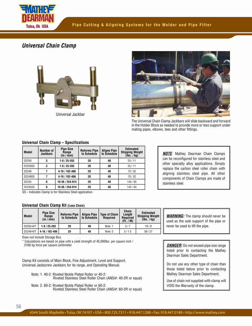
56
P i p e C u t t i n g & A l i g n i n g S y s t e m s f o r t h e W e l d e r a n d P i p e F i t t e r
Universal Chain Clamp
Universal Jackbar
SS - Indicates Clamp is for Stainless Steel application.
Universal Chain Clamp – Specifications
Universal Chain Clamp Kit (Less Chain)
The Universal Chain Clamp Jackbars will slide backward and forward in the Holder Block as needed to provide more or less support under mating pipes, elbows, tees and other fittings.
Does not include Storage Box. * Calculations are based on pipe with a yield strength of 45,000lbs. per square inch / 3168 kg force per square centimeter.
Clamp Kit consists of Main Block, Fine Adjustment, Level and Support, Universal Jackscrew Jackbars for its range, and Operating Manual.
Note: 1. 40-2: Riveted Nickle Plated Roller or 40-2: Riveted Stainless Steel Roller Chain (ANSI#: 40-2R or equal)
Note: 2. 60-2: Riveted Nickle Plated Roller or 60-2: Riveted Stainless Steel Roller Chain (ANSI#: 60-2R or equal)
DANGER: Do not exceed pipe size range listed prior to contacting the Mathey Dearman Sales Department.
Do not use any other type of chain than those listed below prior to contacting Mathey Dearman Sales Department.
Use of chain not supplied with clamp will VOID the Warranty of the clamp.
ModelPipe Size
Range (in / mm)
Reforms Pipe to Schedule
Aligns Pipe to Schedule
Type of Chain Required
Chain Length
Required (Ft. / M)
Estimated Shipping Weight
(lbs. / kg)
D2250-KIT 1-8 / 25-203 20 40 Note: 1 3 / 1 19 / 9
D2249-KIT 4-16 / 102-406 20 40 Note: 2 5 / 1.5 59 / 27
Model Number of Jackbars
Pipe Size Range
(in / mm)Reforms Pipe to Schedule
Aligns Pipe to Schedule
Estimated Shipping Weight
(lbs. / kg)
D2250 3 1-8 / 25-203 20 40 25 / 11
D2250SS 3 1-8 / 25-203 20 40 25 / 11
D2249 7 4-16 / 102-406 20 40 70 / 32
D2249SS 7 4-16 / 102-406 20 40 70 / 32
D2235 8 10-36 / 254-914 20 40 145 / 65
D2235SS 8 10-36 / 254-914 20 40 145 / 65
NOTE: Mathey Dearman Chain Clamps can be reconfigured for stainless steel and other specialty alloy applications. Simply replace the carbon steel roller chain with aligning stainless steel pipe. All other components of Chain Clamps are made of stainless steel.
WARNING: The clamp should never be used as the sole support of the pipe or never be used to lift the pipe.

57
P i p e C u t t i n g & A l i g n i n g S y s t e m s f o r t h e W e l d e r a n d P i p e F i t t e r
• PRECISION ALIGNMENT of large heavy wall pipe or vessels.
• EXTREMELY TOUGH Jackbars form pipe to the desired shape.
• ADAPTABLE—Chain and Jackbar can be added or removed for different diameters.
• INDEPENDENT pivoting of Jackscrew Pads for uneven surfaces.
Double Chain Clamps include:• Length of Chain required for the pipe range.
• Extra Heavy-Duty Jackbars listed for the pipe range.
• Main Block.
• Two (2) Fine Adjustments.
• D251-1036, D251-1036SS, D251-1048, D251-1048SS, D251-1054 and D251-1054SS Supplied with Level and Support Device. (Larger Clamps supplied with Come-A-Long.)
• Jackscrew Wrench.
• Carbon or Stainless Steel Spacing Screws (Optional).
• Operating Instructions.
Double Chain Clamp - D251 Series
Large pipe or tube shells, as large as 20' / 6096mm (as shown in picture) can be aligned, reformed and welded without removal of the Double Chain Clamp, thereby increasing quality of the welding process.
Double Chain Jack Bar
Jackscrew
Fine Adjustment
The Double Chain Clamp is a heavy-duty vessel clamp designed for alignment and reforming of pipes and
vessels 20' / 6M with Schedule 80" wall thickness. Align Schedule 80 pipe and over when no reforming is required with the Double Chain Clamp.
The Extra Heavy-Duty Jackbar and Main Block provide the brute strength to accomplish reforming jobs. Models 10" to 36" thru 10" to 54" come with Level and Support and all other Models come with Cable Hoist. The Double Chain Clamp is available for steel and stainless steel models. All Clamps are shipped in a wooden storage crate.
Double Chain ClampDouble Chain
Main Block
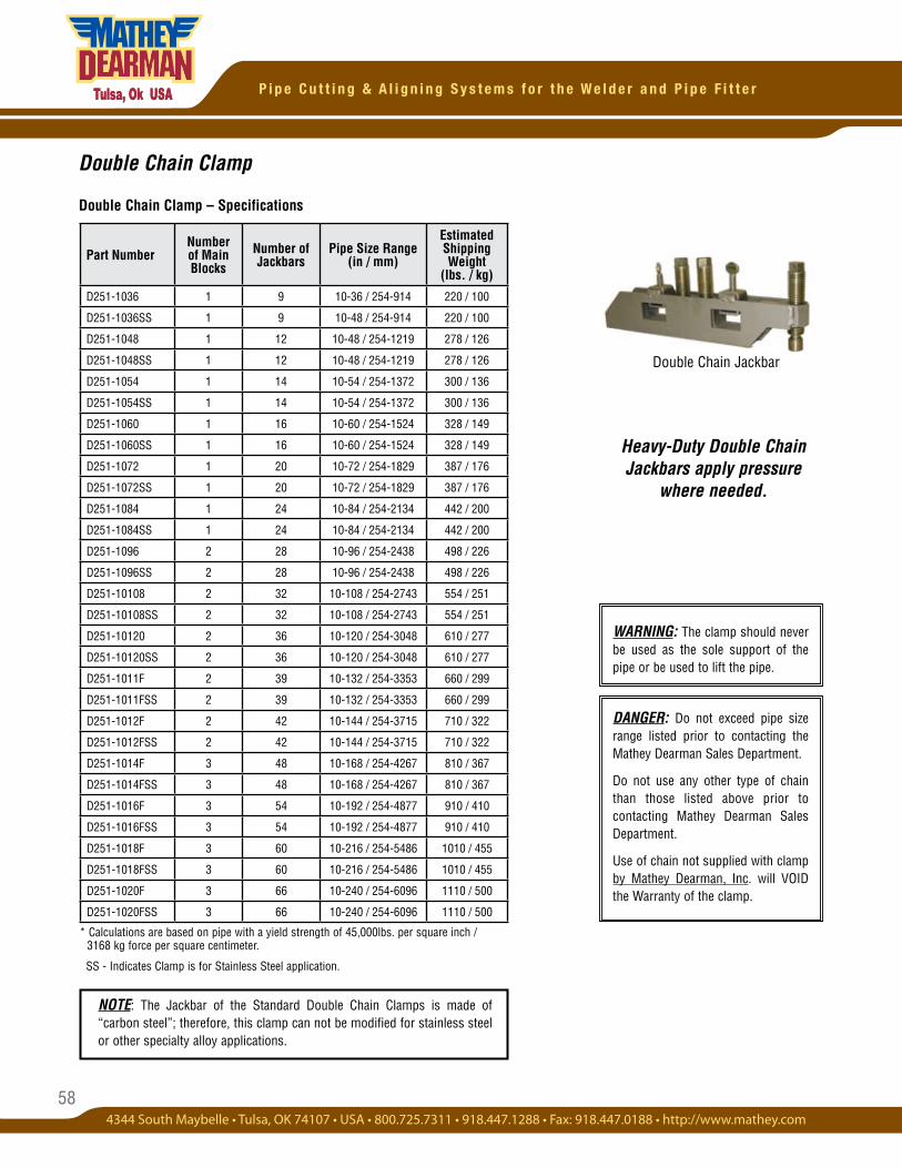
58
P i p e C u t t i n g & A l i g n i n g S y s t e m s f o r t h e W e l d e r a n d P i p e F i t t e r
Double Chain Clamp
Double Chain Clamp – Specifications
* Calculations are based on pipe with a yield strength of 45,000lbs. per square inch / 3168 kg force per square centimeter.
SS - Indicates Clamp is for Stainless Steel application.
Double Chain Jackbar
Heavy-Duty Double Chain Jackbars apply pressure
where needed.
WARNING: The clamp should never be used as the sole support of the pipe or be used to lift the pipe.
DANGER: Do not exceed pipe size range listed prior to contacting the Mathey Dearman Sales Department.
Do not use any other type of chain than those listed above prior to contacting Mathey Dearman Sales Department.
Use of chain not supplied with clamp by Mathey Dearman, Inc. will VOID the Warranty of the clamp.
NOTE: The Jackbar of the Standard Double Chain Clamps is made of “carbon steel”; therefore, this clamp can not be modified for stainless steel or other specialty alloy applications.
Part NumberNumber of Main Blocks
Number of Jackbars
Pipe Size Range (in / mm)
EstimatedShipping Weight
(lbs. / kg)
D251-1036 1 9 10-36 / 254-914 220 / 100
D251-1036SS 1 9 10-48 / 254-914 220 / 100
D251-1048 1 12 10-48 / 254-1219 278 / 126
D251-1048SS 1 12 10-48 / 254-1219 278 / 126
D251-1054 1 14 10-54 / 254-1372 300 / 136
D251-1054SS 1 14 10-54 / 254-1372 300 / 136
D251-1060 1 16 10-60 / 254-1524 328 / 149
D251-1060SS 1 16 10-60 / 254-1524 328 / 149
D251-1072 1 20 10-72 / 254-1829 387 / 176
D251-1072SS 1 20 10-72 / 254-1829 387 / 176
D251-1084 1 24 10-84 / 254-2134 442 / 200
D251-1084SS 1 24 10-84 / 254-2134 442 / 200
D251-1096 2 28 10-96 / 254-2438 498 / 226
D251-1096SS 2 28 10-96 / 254-2438 498 / 226
D251-10108 2 32 10-108 / 254-2743 554 / 251
D251-10108SS 2 32 10-108 / 254-2743 554 / 251
D251-10120 2 36 10-120 / 254-3048 610 / 277
D251-10120SS 2 36 10-120 / 254-3048 610 / 277
D251-1011F 2 39 10-132 / 254-3353 660 / 299
D251-1011FSS 2 39 10-132 / 254-3353 660 / 299
D251-1012F 2 42 10-144 / 254-3715 710 / 322
D251-1012FSS 2 42 10-144 / 254-3715 710 / 322
D251-1014F 3 48 10-168 / 254-4267 810 / 367
D251-1014FSS 3 48 10-168 / 254-4267 810 / 367
D251-1016F 3 54 10-192 / 254-4877 910 / 410
D251-1016FSS 3 54 10-192 / 254-4877 910 / 410
D251-1018F 3 60 10-216 / 254-5486 1010 / 455
D251-1018FSS 3 60 10-216 / 254-5486 1010 / 455
D251-1020F 3 66 10-240 / 254-6096 1110 / 500
D251-1020FSS 3 66 10-240 / 254-6096 1110 / 500
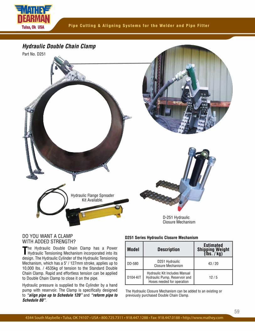
59
P i p e C u t t i n g & A l i g n i n g S y s t e m s f o r t h e W e l d e r a n d P i p e F i t t e r
Hydraulic Double Chain ClampPart No. D251
D251 Series Hydraulic Closure Mechanism
The Hydraulic Closure Mechanism can be added to an existing or previously purchased Double Chain Clamp.
DO YOU WANT A CLAMP WITH ADDED STRENGTH?
The Hydraulic Double Chain Clamp has a Power Hydraulic Tensioning Mechanism incorporated into its
design. The Hydraulic Cylinder of the Hydraulic Tensioning Mechanism, which has a 5" / 127mm stroke, applies up to 10,000 lbs. / 4535kg of tension to the Standard Double Chain Clamp. Rapid and effortless tension can be applied to Double Chain Clamp to close it on the pipe.
Hydraulic pressure is supplied to the Cylinder by a hand pump with reservoir. The Clamp is specifically designed to “align pipe up to Schedule 120” and “reform pipe to Schedule 80”.
D-251 Hydraulic Closure Mechanism
Hydraulic Flange Spreader Kit Available.
Model DescriptionEstimated
Shipping Weight (lbs. / kg)
DD-580 D251 Hydraulic Closure Mechanism 43 / 20
D104-KITHydraulic Kit Includes Manual
Hydraulic Pump, Reservoir and Hoses needed for operation
12 / 5
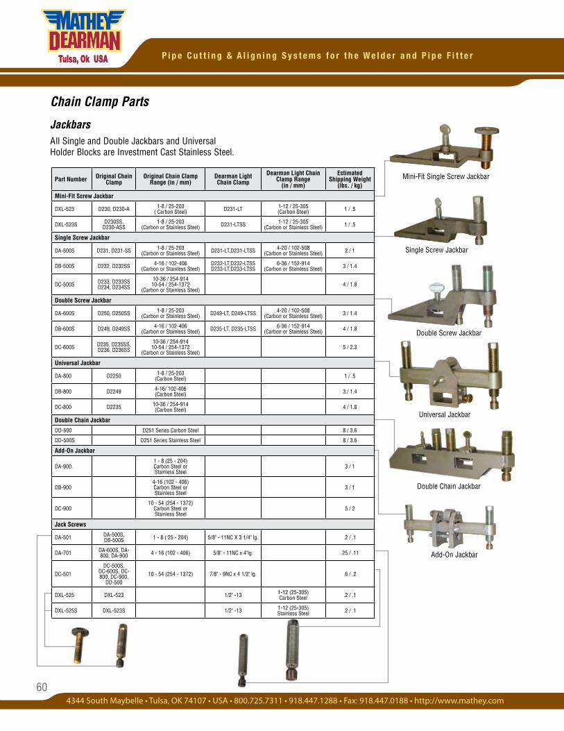
60
P i p e C u t t i n g & A l i g n i n g S y s t e m s f o r t h e W e l d e r a n d P i p e F i t t e r
Mini-Fit Single Screw Jackbar
Chain Clamp Parts
JackbarsAll Single and Double Jackbars and Universal Holder Blocks are Investment Cast Stainless Steel.
Part Number Original Chain Clamp
Original Chain Clamp Range (in / mm)
Dearman LightChain Clamp
Dearman Light Chain Clamp Range
(in / mm)
Estimated Shipping Weight
(lbs. / kg)
Mini-Fit Screw Jackbar
DXL-523 D230, D230-A 1-8 / 25-203( Carbon Steel) D231-LT 1-12 / 25-305
(Carbon Steel) 1 / .5
DXL-523S D230SS, D230-ASS
1-8 / 25-203(Carbon or Stainless Steel) D231-LTSS 1-12 / 25-305
(Carbon or Stainless Steel) 1 / .5
Single Screw Jackbar
DA-500S D231, D231-SS 1-8 / 25-203(Carbon or Stainless Steel) D231-LT,D231-LTSS 4-20 / 102-508
(Carbon or Stainless Steel) 2 / 1
DB-500S D232, D232SS 4-16 / 102-406(Carbon or Stainless Steel)
D232-LT,D232-LTSSD233-LT,D233-LTSS
6-36 / 152-914(Carbon or Stainless Steel) 3 / 1.4
DC-500S D233, D233SSD234, D234SS
10-36 / 254-91410-54 / 254-1372
(Carbon or Stainless Steel)4 / 1.8
Double Screw Jackbar
DA-600S D250, D250SS 1-8 / 25-203(Carbon or Stainless Steel) D249-LT, D249-LTSS 4-20 / 102-508
(Carbon or Stainless Steel) 3 / 1.4
DB-600S D249, D249SS 4-16 / 102-406(Carbon or Stainless Steel) D235-LT, D235-LTSS 6-36 / 152-914
(Carbon or Stainless Steel) 4 / 1.8
DC-600S D235, D235SS,D236, D236SS
10-36 / 254-91410-54 / 254-1372
(Carbon or Stainless Steel)5 / 2.3
Universal Jackbar
DA-800 D2250 1-8 / 25-203(Carbon Steel) 1 / .5
DB-800 D2249 4-16/ 102-406(Carbon Steel) 3 / 1.4
DC-800 D2235 10-36 / 254-914(Carbon Steel) 4 / 1.8
Double Chain Jackbar
DD-500 D251 Series Carbon Steel 8 / 3.6
DD-500S D251 Series Stainless Steel 8 / 3.6
Add-On Jackbar
DA-900.1 - 8 (25 - 204) Carbon Steel or Stainless Steel
3 / 1
DB-9004-16 (102 - 406) Carbon Steel or Stainless Steel
3 / 1
DC-90010 - 54 (254 - 1372)
Carbon Steel or Stainless Steel
5 / 2
Jack Screws
DA-501 DA-500S, DB-500S 1 - 8 ( 25 - 204) 5/8" - 11NC X 3 1/4" lg. .2 / .1
DA-701 DA-600S, DA-800, DA-900 4 - 16 (102 - 406) 5/8" - 11NC x 4"lg. .25 / .11
DC-501DC-500S,
DC-600S, DC-800, DC-900,
DD-50010 - 54 (254 - 1372) 7/8" - 9NC x 4 1/2" lg. .6 / .2
DXL-525 DXL-523 1/2" -13 1-12 (25-305) Carbon Steel .2 / .1
DXL-525S DXL-523S 1/2" -13 1-12 (25-305)Stainless Steel .2 / .1
Double Chain Jackbar
Single Screw Jackbar
Universal Jackbar
Add-On Jackbar
Double Screw Jackbar
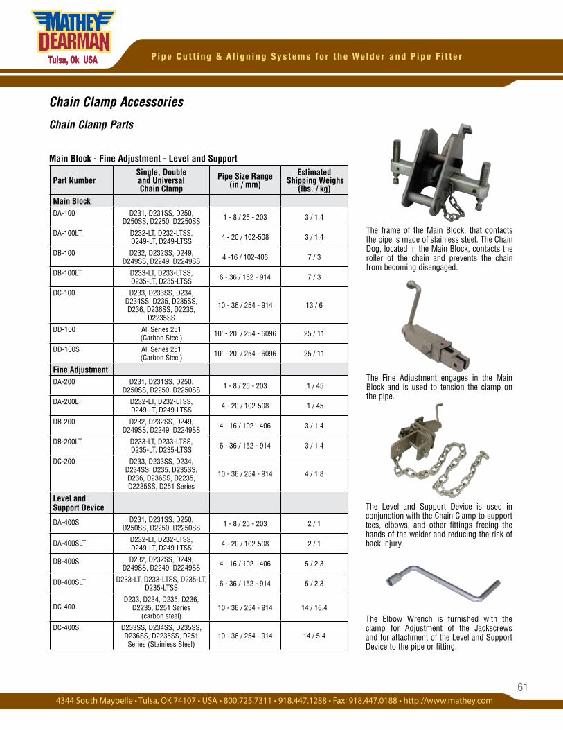
61
P i p e C u t t i n g & A l i g n i n g S y s t e m s f o r t h e W e l d e r a n d P i p e F i t t e r
Chain Clamp Accessories
Chain Clamp Parts
Main Block - Fine Adjustment - Level and Support
The Fine Adjustment engages in the Main Block and is used to tension the clamp on the pipe.
The frame of the Main Block, that contacts the pipe is made of stainless steel. The Chain Dog, located in the Main Block, contacts the roller of the chain and prevents the chain from becoming disengaged.
The Level and Support Device is used in conjunction with the Chain Clamp to support tees, elbows, and other fittings freeing the hands of the welder and reducing the risk of back injury.
Part NumberSingle, Double and Universal Chain Clamp
Pipe Size Range (in / mm)
Estimated Shipping Weighs
(lbs. / kg)Main BlockDA-100 D231, D231SS, D250,
D250SS, D2250, D2250SS 1 - 8 / 25 - 203 3 / 1.4
DA-100LT D232-LT, D232-LTSS, D249-LT, D249-LTSS 4 - 20 / 102-508 3 / 1.4
DB-100 D232, D232SS, D249, D249SS, D2249, D2249SS 4 -16 / 102-406 7 / 3
DB-100LT D233-LT, D233-LTSS, D235-LT, D235-LTSS 6 - 36 / 152 - 914 7 / 3
DC-100 D233, D233SS, D234, D234SS, D235, D235SS, D236, D236SS, D2235,
D2235SS
10 - 36 / 254 - 914 13 / 6
DD-100 All Series 251 (Carbon Steel) 10' - 20' / 254 - 6096 25 / 11
DD-100S All Series 251 (Carbon Steel) 10' - 20' / 254 - 6096 25 / 11
Fine AdjustmentDA-200 D231, D231SS, D250,
D250SS, D2250, D2250SS 1 - 8 / 25 - 203 .1 / 45
DA-200LT D232-LT, D232-LTSS, D249-LT, D249-LTSS 4 - 20 / 102-508 .1 / 45
DB-200 D232, D232SS, D249, D249SS, D2249, D2249SS 4 - 16 / 102 - 406 3 / 1.4
DB-200LT D233-LT, D233-LTSS, D235-LT, D235-LTSS 6 - 36 / 152 - 914 3 / 1.4
DC-200 D233, D233SS, D234, D234SS, D235, D235SS, D236, D236SS, D2235, D2235SS, D251 Series
10 - 36 / 254 - 914 4 / 1.8
Level and Support Device
DA-400S D231, D231SS, D250, D250SS, D2250, D2250SS 1 - 8 / 25 - 203 2 / 1
DA-400SLT D232-LT, D232-LTSS, D249-LT, D249-LTSS 4 - 20 / 102-508 2 / 1
DB-400S D232, D232SS, D249, D249SS, D2249, D2249SS 4 - 16 / 102 - 406 5 / 2.3
DB-400SLT D233-LT, D233-LTSS, D235-LT, D235-LTSS 6 - 36 / 152 - 914 5 / 2.3
DC-400D233, D234, D235, D236,
D2235, D251 Series (carbon steel)
10 - 36 / 254 - 914 14 / 16.4
DC-400S D233SS, D234SS, D235SS, D236SS, D2235SS, D251 Series (Stainless Steel)
10 - 36 / 254 - 914 14 / 5.4
The Elbow Wrench is furnished with the clamp for Adjustment of the Jackscrews and for attachment of the Level and Support Device to the pipe or fitting.
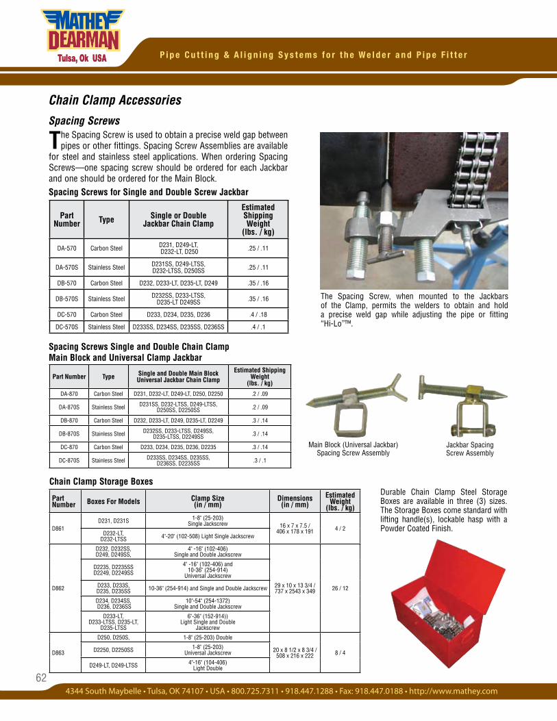
62
P i p e C u t t i n g & A l i g n i n g S y s t e m s f o r t h e W e l d e r a n d P i p e F i t t e r
Chain Clamp Accessories
Spacing Screws
The Spacing Screw is used to obtain a precise weld gap between pipes or other fittings. Spacing Screw Assemblies are available
for steel and stainless steel applications. When ordering Spacing Screws—one spacing screw should be ordered for each Jackbar and one should be ordered for the Main Block.
Spacing Screws Single and Double Chain Clamp Main Block and Universal Clamp Jackbar
Jackbar Spacing Screw Assembly
Main Block (Universal Jackbar) Spacing Screw Assembly
Spacing Screws for Single and Double Screw Jackbar
Chain Clamp Storage BoxesDurable Chain Clamp Steel Storage Boxes are available in three (3) sizes. The Storage Boxes come standard with lifting handle(s), lockable hasp with a Powder Coated Finish.
The Spacing Screw, when mounted to the Jackbars of the Clamp, permits the welders to obtain and hold a precise weld gap while adjusting the pipe or fitting “Hi-Lo”™.
Part Number Type Single or Double
Jackbar Chain Clamp
EstimatedShipping Weight
(lbs. / kg)
DA-570 Carbon Steel D231, D249-LT, D232-LT, D250 .25 / .11
DA-570S Stainless Steel D231SS, D249-LTSS, D232-LTSS, D250SS .25 / .11
DB-570 Carbon Steel D232, D233-LT, D235-LT, D249 .35 / .16
DB-570S Stainless Steel D232SS, D233-LTSS, D235-LT D249SS .35 / .16
DC-570 Carbon Steel D233, D234, D235, D236 .4 / .18
DC-570S Stainless Steel D233SS, D234SS, D235SS, D236SS .4 / .1
Part Number Boxes For Models Clamp Size
(in / mm)Dimensions
(in / mm)Estimated
Weight(lbs. / kg)
D861D231, D231S 1-8" (25-203)
Single Jackscrew 16 x 7 x 7.5 / 406 x 178 x 191 4 / 2
D232-LT, D232-LTSS 4"-20" (102-508) Light Single Jackscrew
D862
D232, D232SS, D249, D249SS,
4" -16" (102-406) Single and Double Jackscrew
29 x 10 x 13 3/4 / 737 x 2543 x 349 26 / 12
D2235, D2235SS D2249, D2249SS
4" -16" (102-406) and 10-36" (254-914)
Universal Jackscrew
D233, D233S, D235, D235SS 10-36" (254-914) and Single and Double Jackscrew
D234, D234SS, D236, D236SS
10"-54" (254-1372) Single and Double Jackscrew
D233-LT, D233-LTSS, D235-LT,
D235-LTSS
6"-36" (152-914)) Light Single and Double
Jackscrew
D863
D250, D250S, 1-8" (25-203) Double
20 x 8 1/2 x 8 3/4 / 508 x 216 x 222 8 / 4D2250, D2250SS 1-8" (25-203)
Universal Jackscrew
D249-LT, D249-LTSS 4"-16" (104-406) Light Double
Part Number Type Single and Double Main Block Universal Jackbar Chain Clamp
Estimated Shipping Weight
(lbs. / kg)
DA-870 Carbon Steel D231, D232-LT, D249-LT, D250, D2250 .2 / .09
DA-870S Stainless Steel D231SS, D232-LTSS, D249-LTSS, D250SS, D2250SS .2 / .09
DB-870 Carbon Steel D232, D233-LT, D249, D235-LT, D2249 .3 / .14
DB-870S Stainless Steel D232SS, D233-LTSS, D249SS, D235-LTSS, D2249SS .3 / .14
DC-870 Carbon Steel D233, D234, D235, D236, D2235 .3 / .14
DC-870S Stainless Steel D233SS, D234SS, D235SS, D236SS, D2235SS .3 / .1
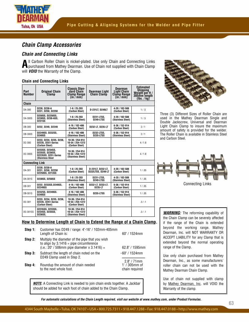
63
P i p e C u t t i n g & A l i g n i n g S y s t e m s f o r t h e W e l d e r a n d P i p e F i t t e r
Chain Clamp Accessories
Chain and Connecting Links
Step 1: Customer has D249 / range: 4"-16" / 102mm-405mm Length of Chain is: 60" / 1524mm
Step 2: Multiply the diameter of the pipe that you wish to align by 3.1416 = pipe circumference (i.e.: 20" / 506mm pipe diameter x 3.1416) = 62.8" / 1595mm
Step 3: Subtract the length of chain noted on the -60" / 1524mm D249 Clamp used in Step 2.
Step 4: Roundup the amount of chain needed 1' / 305mm of to the next whole foot. chain required
2.8" / 71mm
How to Determine Length of Chain to Extend the Range of a Chain Clamp.
A ll Carbon Roller Chain is nickel-plated. Use only Chain and Connecting Links purchased from Mathey Dearman. Use of Chain not supplied with Chain Clamp
will VOID the Warranty of the Clamp.
Chain and Connecting Links
Connecting Links
Three (3) Different Sizes of Roller Chain are used in the Mathey Dearman Single and Double Jackscrew, Universal and Dearman Light Chain Clamp to insure the maximum amount of safety is provided for the welder. The Roller Chain is available in Stainless Steel and Carbon Steel.
Part Number
Original Chain Clamp
Classic Stan-dard Chain
Clamp Range (in / mm)
Dearman Light Chain Clamp
Dearman Light Chain
Clamp Range (in / mm)
Estimated Shipping
Weight per ft / 305mm length
(lbs. / kg)
Chain
DA-300 D230, D230-A D231, D250, D2250
1-8 / 25-203 (Carbon Steel) D-231LT, D249LT 4-20 / 102-508
(Carbon Steel) 1 / .5
DA-300SD250SS, D2250SS, D230SS, D230-ASS, D231SS
1-8 / 25-203 (Stainless Steel)
D231-LTSS, D249-LTSS
4-20 / 102-508 (Stainless Steel) 1 / .5
DB-300 D232, D249, D2249 4-16 / 102-406 (Carbon Steel) D232-LT, D235-LT 6-36 / 152-914
(Carbon Steel) 2 / 1
DB-300S D2249SS. D232SS, D249SS
4-16 / 102-406 (Stainless Steel)
D232-LTSS, D235-LTSS
6-36 / 152-914 (Stainless Steel) 2 / 1
DC-300D233, D234, D235, D236, D2235, D251-Series (Carbon Steel)
10-36 / 254-914 10-54 / 254-1372
(Carbon Steel)4 / 1.8
DC-300S
D233SS, D234SS, D235SS, D236SS, D2235SS, D251-Series (Stainless Steel
10-36 / 254-914 10-54 / 254-1372 (Stainless Steel)
4 / 1.8
Connecting Link
DA-301D230, D230-A D231, D250, D2250 D2250SS, D213SS
1-8 / 25-203 (Carbon Steel)
D-231LT, D232-LT, D232LTSS, D249-LT
4-20 / 102-508 (Carbon Steel) 1 / .05
DA-301S D230SS, D250SS 1-8 / 25-203 (Stainless Steel)
D231-LTSS, D249-LTSS
4-20 / 102-508 (Stainless Steel) 1 / .05
DB-301 D232, D233SS,D249SS, D2249SS
4-16 / 102-406 (Carbon Steel)
D232-LT, D233-LT. D235-LT
6-36 / 152-914 (Carbon Steel) 1 / .05
DB-301S D232SS, D2249SS. D249SS
4-16 / 102-406 (Stainless Steel) D235-LTSS 6-36 / 152-914
(Stainless Steel) 1 / .05
DC-301D233. D234, D235, D236, D2235, D251-Series (Carbon Steel)
10-36 / 254-914 10-54 / 254-1372
(Carbon Steel).3 / .1
DC-301SSD2235SS, D233SS, D234SS, D235SS, D236SS,
10-36 / 254-914 10-54 / 254-1372 (Stainless Steel)
.3 / .1
For automatic calculations of the Chain Length required, visit our website at www.mathey.com, under Product Formulas.
NOTE: A Connecting Link is needed to join chain ends together. A Jackbar should be added for each foot of chain added to the Chain Clamp.
WARNING: The reforming capability of the Chain Clamp can be severely affected if the range of the Chain is extended beyond the working range. Mathey Dearman, Inc. will NOT WARRANTY OR ACCEPT LIABILITY for any Clamp that is extended beyond the normal operating range of the Clamp.
Use only chain purchased from Mathey Dearman, Inc., as some manufacturers' roller chain can not be used with the Mathey Dearman Chain Clamp.
Use of chain not supplied with clamp by Mathey Dearman, Inc. will VOID the Warranty of the clamp.
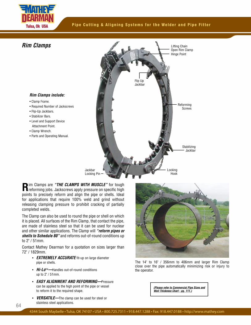
64
P i p e C u t t i n g & A l i g n i n g S y s t e m s f o r t h e W e l d e r a n d P i p e F i t t e r
Rim Clamps
Reforming Screws
Locking Hook
Hinge Point
Lifting Chain Open Rim Clamp
Stabilizing Jackbar
Jackbar Locking Pin
Flip Up Jackbar
Rim Clamps are “THE CLAMPS WITH MUSCLE” for tough reforming jobs. Jackscrews apply pressure on specific high
points to precisely reform and align the pipe or shells. Ideal for applications that require 100% weld and grind without releasing clamping pressure to prohibit cracking of partially completed welds.
The Clamp can also be used to round the pipe or shell on which it is placed. All surfaces of the Rim Clamp, that contact the pipe, are made of stainless steel so that it can be used for nuclear and other similar applications. The Clamp will “reform pipes or shells to Schedule 80” and reforms out-of-round conditions up to 2" / 51mm.
Contact Mathey Dearman for a quotation on sizes larger than 72" / 1829mm.
The 14" to 16" / 356mm to 406mm and larger Rim Clamp close over the pipe automatically minimizing risk or injury to the operator.
• EXTREMELY ACCURATE fit-up on large diameter pipe or shells.
• Hi-Lo™—Handles out-of-round conditions up to 2" / 51mm.
• EASY ALIGNMENT AND REFORMING—Pressure can be applied to the high point of the pipe or vessel to reform it to the required shape.
• VERSATILE—The clamp can be used for steel or stainless steel applications.
Rim Clamps include:• Clamp Frame.• Required Number of Jackscrews• Flip-Up Jackbars. • Stabilizer Bars.• Level and Support Device Attachment Point.• Clamp Wrench.• Parts and Operating Manual.
(Please refer to Commercial Pipe Sizes and Wall Thickness Chart - pg. 111.)
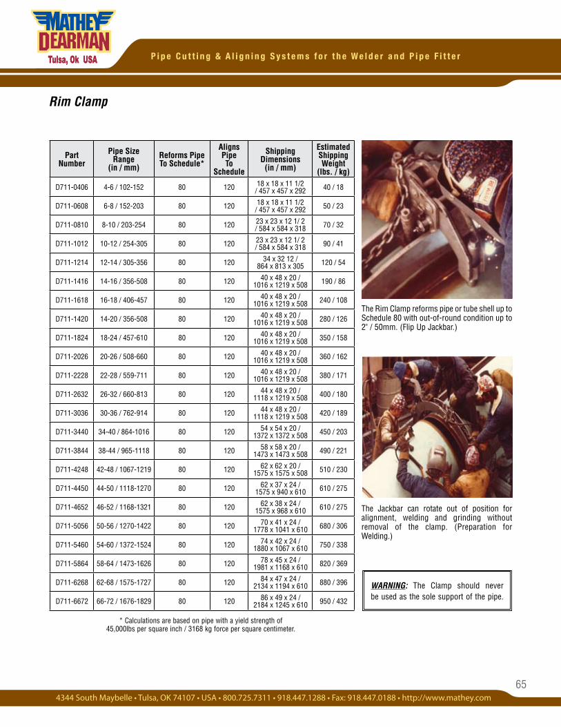
65
P i p e C u t t i n g & A l i g n i n g S y s t e m s f o r t h e W e l d e r a n d P i p e F i t t e r
Rim Clamp
* Calculations are based on pipe with a yield strength of 45,000lbs per square inch / 3168 kg force per square centimeter.
The Rim Clamp reforms pipe or tube shell up to Schedule 80 with out-of-round condition up to 2" / 50mm. (Flip Up Jackbar.)
The Jackbar can rotate out of position for alignment, welding and grinding without removal of the clamp. (Preparation for Welding.)
Part Number
Pipe Size Range
(in / mm)Reforms PipeTo Schedule*
Aligns PipeTo
Schedule
Shipping Dimensions
(in / mm)
Estimated Shipping Weight
(lbs. / kg)
D711-0406 4-6 / 102-152 80 120 18 x 18 x 11 1/2 / 457 x 457 x 292 40 / 18
D711-0608 6-8 / 152-203 80 120 18 x 18 x 11 1/2 / 457 x 457 x 292 50 / 23
D711-0810 8-10 / 203-254 80 120 23 x 23 x 12 1/ 2 / 584 x 584 x 318 70 / 32
D711-1012 10-12 / 254-305 80 120 23 x 23 x 12 1/ 2 / 584 x 584 x 318 90 / 41
D711-1214 12-14 / 305-356 80 120 34 x 32 12 / 864 x 813 x 305 120 / 54
D711-1416 14-16 / 356-508 80 120 40 x 48 x 20 / 1016 x 1219 x 508 190 / 86
D711-1618 16-18 / 406-457 80 120 40 x 48 x 20 / 1016 x 1219 x 508 240 / 108
D711-1420 14-20 / 356-508 80 120 40 x 48 x 20 / 1016 x 1219 x 508 280 / 126
D711-1824 18-24 / 457-610 80 120 40 x 48 x 20 / 1016 x 1219 x 508 350 / 158
D711-2026 20-26 / 508-660 80 120 40 x 48 x 20 / 1016 x 1219 x 508 360 / 162
D711-2228 22-28 / 559-711 80 120 40 x 48 x 20 / 1016 x 1219 x 508 380 / 171
D711-2632 26-32 / 660-813 80 120 44 x 48 x 20 / 1118 x 1219 x 508 400 / 180
D711-3036 30-36 / 762-914 80 120 44 x 48 x 20 / 1118 x 1219 x 508 420 / 189
D711-3440 34-40 / 864-1016 80 120 54 x 54 x 20 / 1372 x 1372 x 508 450 / 203
D711-3844 38-44 / 965-1118 80 120 58 x 58 x 20 / 1473 x 1473 x 508 490 / 221
D711-4248 42-48 / 1067-1219 80 120 62 x 62 x 20 / 1575 x 1575 x 508 510 / 230
D711-4450 44-50 / 1118-1270 80 120 62 x 37 x 24 / 1575 x 940 x 610 610 / 275
D711-4652 46-52 / 1168-1321 80 120 62 x 38 x 24 / 1575 x 968 x 610 610 / 275
D711-5056 50-56 / 1270-1422 80 120 70 x 41 x 24 / 1778 x 1041 x 610 680 / 306
D711-5460 54-60 / 1372-1524 80 120 74 x 42 x 24 / 1880 x 1067 x 610 750 / 338
D711-5864 58-64 / 1473-1626 80 120 78 x 45 x 24 / 1981 x 1168 x 610 820 / 369
D711-6268 62-68 / 1575-1727 80 120 84 x 47 x 24 / 2134 x 1194 x 610 880 / 396
D711-6672 66-72 / 1676-1829 80 120 86 x 49 x 24 / 2184 x 1245 x 610 950 / 432
WARNING: The Clamp should never be used as the sole support of the pipe.
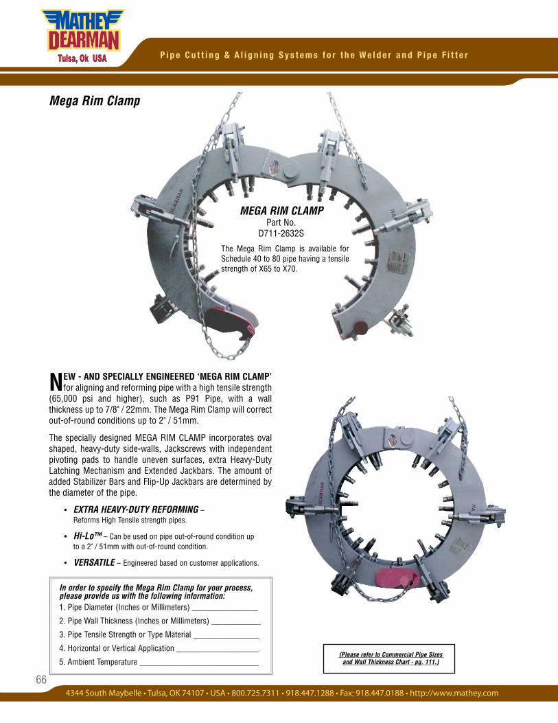
66
P i p e C u t t i n g & A l i g n i n g S y s t e m s f o r t h e W e l d e r a n d P i p e F i t t e r
Mega Rim Clamp
In order to specify the Mega Rim Clamp for your process, please provide us with the following information:1. Pipe Diameter (Inches or Millimeters) ________________
2. Pipe Wall Thickness (Inches or Millimeters) ____________
3. Pipe Tensile Strength or Type Material ________________
4. Horizontal or Vertical Application ____________________
5. Ambient Temperature _____________________________
NEW - AND SPECIALLY ENGINEERED ‘MEGA RIM CLAMP’ for aligning and reforming pipe with a high tensile strength
(65,000 psi and higher), such as P91 Pipe, with a wall thickness up to 7/8" / 22mm. The Mega Rim Clamp will correct out-of-round conditions up to 2" / 51mm.
The specially designed MEGA RIM CLAMP incorporates oval shaped, heavy-duty side-walls, Jackscrews with independent pivoting pads to handle uneven surfaces, extra Heavy-Duty Latching Mechanism and Extended Jackbars. The amount of added Stabilizer Bars and Flip-Up Jackbars are determined by the diameter of the pipe.
• EXTRA HEAVY-DUTY REFORMING – Reforms High Tensile strength pipes.
• Hi-Lo™ – Can be used on pipe out-of-round condition up to a 2" / 51mm with out-of-round condition.
• VERSATILE – Engineered based on customer applications.
(Please refer to Commercial Pipe Sizes and Wall Thickness Chart - pg. 111.)
MEGA RIM CLAMP Part No.
D711-2632S
The Mega Rim Clamp is available for Schedule 40 to 80 pipe having a tensile strength of X65 to X70.
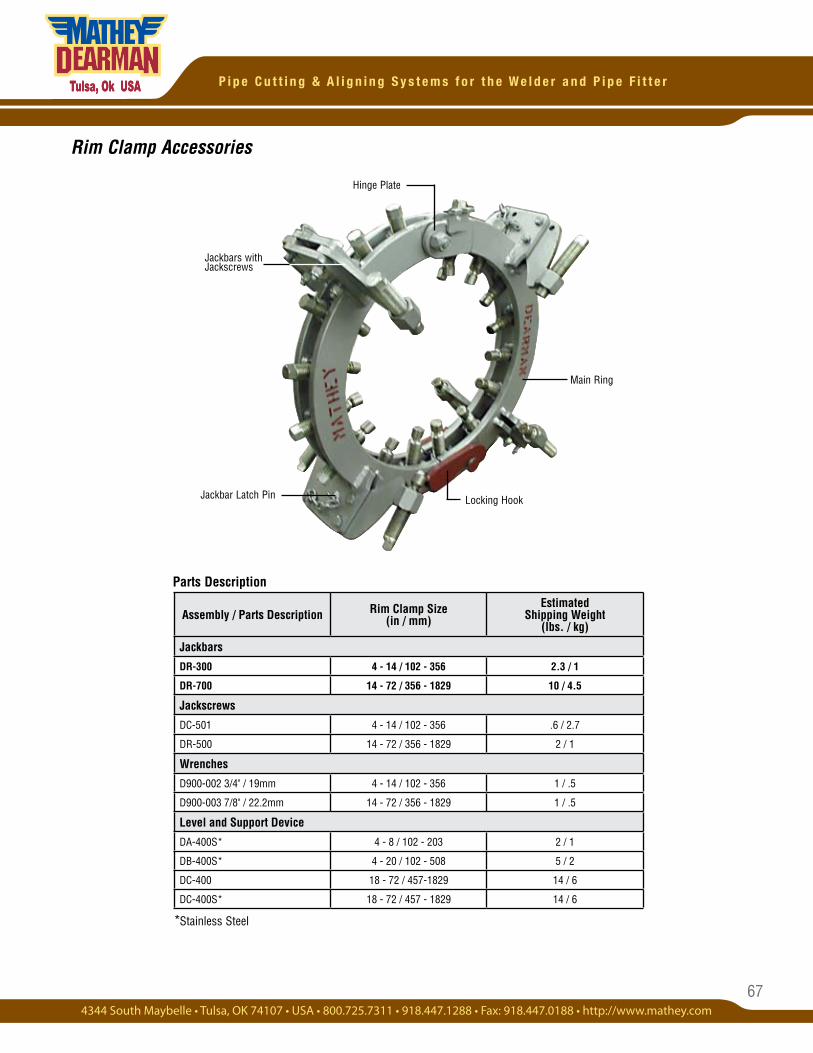
67
P i p e C u t t i n g & A l i g n i n g S y s t e m s f o r t h e W e l d e r a n d P i p e F i t t e r
Rim Clamp Accessories
Parts Description
Jackbars with Jackscrews
Locking HookJackbar Latch Pin
Main Ring
Hinge Plate
*Stainless Steel
Assembly / Parts Description Rim Clamp Size(in / mm)
EstimatedShipping Weight
(lbs. / kg)
Jackbars
DR-300 4 - 14 / 102 - 356 2.3 / 1
DR-700 14 - 72 / 356 - 1829 10 / 4.5
Jackscrews
DC-501 4 - 14 / 102 - 356 .6 / 2.7
DR-500 14 - 72 / 356 - 1829 2 / 1
Wrenches
D900-002 3/4" / 19mm 4 - 14 / 102 - 356 1 / .5
D900-003 7/8" / 22.2mm 14 - 72 / 356 - 1829 1 / .5
Level and Support Device
DA-400S* 4 - 8 / 102 - 203 2 / 1
DB-400S* 4 - 20 / 102 - 508 5 / 2
DC-400 18 - 72 / 457-1829 14 / 6
DC-400S* 18 - 72 / 457 - 1829 14 / 6
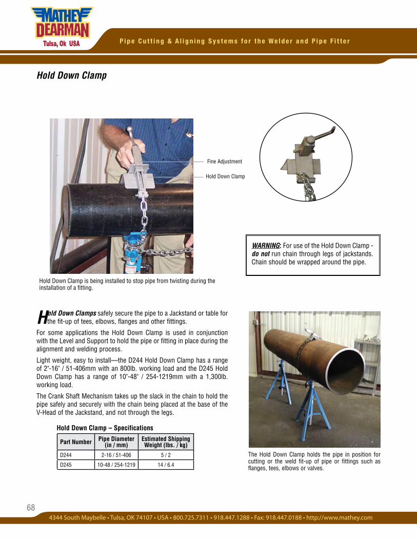
68
P i p e C u t t i n g & A l i g n i n g S y s t e m s f o r t h e W e l d e r a n d P i p e F i t t e r
Hold Down Clamp
Hold Down Clamp – Specifications
The Hold Down Clamp holds the pipe in position for cutting or the weld fit-up of pipe or fittings such as flanges, tees, elbows or valves.
Hold Down Clamps safely secure the pipe to a Jackstand or table for the fit-up of tees, elbows, flanges and other fittings.
For some applications the Hold Down Clamp is used in conjunction with the Level and Support to hold the pipe or fitting in place during the alignment and welding process.
Light weight, easy to install—the D244 Hold Down Clamp has a range of 2"-16" / 51-406mm with an 800lb. working load and the D245 Hold Down Clamp has a range of 10"-48" / 254-1219mm with a 1,300lb. working load.
The Crank Shaft Mechanism takes up the slack in the chain to hold the pipe safely and securely with the chain being placed at the base of the V-Head of the Jackstand, and not through the legs.
Fine Adjustment
Part Number Pipe Diameter (in / mm)
Estimated Shipping Weight (lbs. / kg)
D244 2-16 / 51-406 5 / 2
D245 10-48 / 254-1219 14 / 6.4
Hold Down Clamp is being installed to stop pipe from twisting during the installation of a fitting.
Hold Down Clamp
WARNING: For use of the Hold Down Clamp - do not run chain through legs of jackstands. Chain should be wrapped around the pipe.
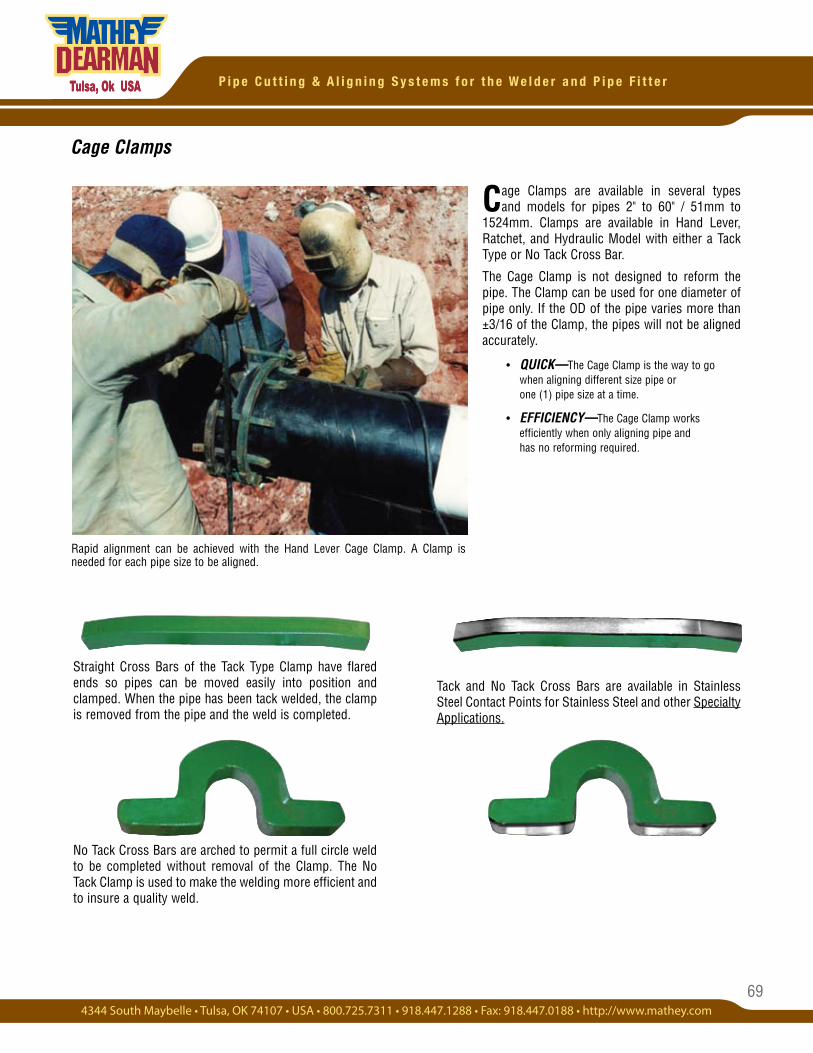
69
P i p e C u t t i n g & A l i g n i n g S y s t e m s f o r t h e W e l d e r a n d P i p e F i t t e r
Cage Clamps
Rapid alignment can be achieved with the Hand Lever Cage Clamp. A Clamp is needed for each pipe size to be aligned.
Straight Cross Bars of the Tack Type Clamp have flared ends so pipes can be moved easily into position and clamped. When the pipe has been tack welded, the clamp is removed from the pipe and the weld is completed.
No Tack Cross Bars are arched to permit a full circle weld to be completed without removal of the Clamp. The No Tack Clamp is used to make the welding more efficient and to insure a quality weld.
Cage Clamps are available in several types and models for pipes 2" to 60" / 51mm to
1524mm. Clamps are available in Hand Lever, Ratchet, and Hydraulic Model with either a Tack Type or No Tack Cross Bar.
The Cage Clamp is not designed to reform the pipe. The Clamp can be used for one diameter of pipe only. If the OD of the pipe varies more than ±3/16 of the Clamp, the pipes will not be aligned accurately.
• QUICK—The Cage Clamp is the way to go when aligning different size pipe or one (1) pipe size at a time.
• EFFICIENCY—The Cage Clamp works efficiently when only aligning pipe and has no reforming required.
Tack and No Tack Cross Bars are available in Stainless Steel Contact Points for Stainless Steel and other Specialty Applications.
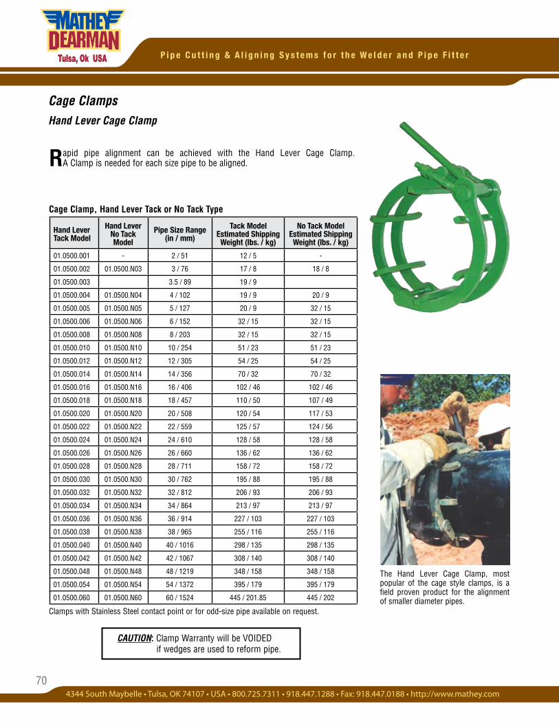
70
P i p e C u t t i n g & A l i g n i n g S y s t e m s f o r t h e W e l d e r a n d P i p e F i t t e r
Rapid pipe alignment can be achieved with the Hand Lever Cage Clamp. A Clamp is needed for each size pipe to be aligned.
Cage ClampsHand Lever Cage Clamp
Clamps with Stainless Steel contact point or for odd-size pipe available on request.
Cage Clamp, Hand Lever Tack or No Tack Type
The Hand Lever Cage Clamp, most popular of the cage style clamps, is a field proven product for the alignment of smaller diameter pipes.
Hand Lever Tack Model
Hand Lever No Tack Model
Pipe Size Range (in / mm)
Tack ModelEstimated Shipping Weight (lbs. / kg)
No Tack ModelEstimated Shipping Weight (lbs. / kg)
01.0500.001 - 2 / 51 12 / 5 -
01.0500.002 01.0500.N03 3 / 76 17 / 8 18 / 8
01.0500.003 3.5 / 89 19 / 9
01.0500.004 01.0500.N04 4 / 102 19 / 9 20 / 9
01.0500.005 01.0500.N05 5 / 127 20 / 9 32 / 15
01.0500.006 01.0500.N06 6 / 152 32 / 15 32 / 15
01.0500.008 01.0500.N08 8 / 203 32 / 15 32 / 15
01.0500.010 01.0500.N10 10 / 254 51 / 23 51 / 23
01.0500.012 01.0500.N12 12 / 305 54 / 25 54 / 25
01.0500.014 01.0500.N14 14 / 356 70 / 32 70 / 32
01.0500.016 01.0500.N16 16 / 406 102 / 46 102 / 46
01.0500.018 01.0500.N18 18 / 457 110 / 50 107 / 49
01.0500.020 01.0500.N20 20 / 508 120 / 54 117 / 53
01.0500.022 01.0500.N22 22 / 559 125 / 57 124 / 56
01.0500.024 01.0500.N24 24 / 610 128 / 58 128 / 58
01.0500.026 01.0500.N26 26 / 660 136 / 62 136 / 62
01.0500.028 01.0500.N28 28 / 711 158 / 72 158 / 72
01.0500.030 01.0500.N30 30 / 762 195 / 88 195 / 88
01.0500.032 01.0500.N32 32 / 812 206 / 93 206 / 93
01.0500.034 01.0500.N34 34 / 864 213 / 97 213 / 97
01.0500.036 01.0500.N36 36 / 914 227 / 103 227 / 103
01.0500.038 01.0500.N38 38 / 965 255 / 116 255 / 116
01.0500.040 01.0500.N40 40 / 1016 298 / 135 298 / 135
01.0500.042 01.0500.N42 42 / 1067 308 / 140 308 / 140
01.0500.048 01.0500.N48 48 / 1219 348 / 158 348 / 158
01.0500.054 01.0500.N54 54 / 1372 395 / 179 395 / 179
01.0500.060 01.0500.N60 60 / 1524 445 / 201.85 445 / 202
CAUTION: Clamp Warranty will be VOIDED if wedges are used to reform pipe.
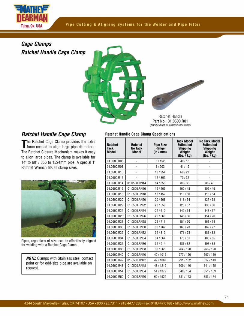
71
P i p e C u t t i n g & A l i g n i n g S y s t e m s f o r t h e W e l d e r a n d P i p e F i t t e r
Ratchet Handle Cage Clamp
The Ratchet Cage Clamp provides the extra force needed to align large pipe diameters.
The Ratchet Closure Mechanism makes it easy to align large pipes. The clamp is available for 14" to 60" / 356 to 1524mm pipe. A special 1" Ratchet Wrench fits all clamp sizes.
NOTE: Clamps with Stainless steel contact point or for odd-size pipe are available on request.
Cage ClampsRatchet Handle Cage Clamp
Ratchet Handle Cage Clamp Specifications
Pipes, regardless of size, can be effortlessly aligned for welding with a Ratchet Cage Clamp.
Ratchet Handle Part No.: 01.0500.R01
(Handle must be ordered separately.)
Ratchet Tack Model
Ratchet No Tack Model
Pipe Size Range
(in / mm)
Tack Model Estimated Shipping Weight
(lbs. / kg)
No Tack Model Estimated Shipping Weight
(lbs. / kg)
01.0500.R06 - 6 / 152 40 / 18 -
01.0500.R08 - 8 / 203 41 / 19 -
01.0500.R10 - 10 / 254 60 / 27 -
01.0500.R12 - 12 / 305 70 / 32 -
01.0500.R14 01.0500-RN14 14 / 356 80 / 36 88 / 40
01.0500.R16 01.0500.RN16 16 / 406 100 / 48 109 / 49
01.0500.R18 01.0500.RN18 18 / 457 110 / 50 118 / 54
01.0500.R20 01.0500.RN20 20 / 508 118 / 54 127 / 58
01.0500.R22 01.0500.RN22 22 / 559 125 / 57 133 / 60
01.0500.R24 01.0500.RN24 24 / 610 140 / 64 148 / 67
01.0500.R26 01.0500.RN26 26 / 660 145 / 66 154 / 70
01.0500.R28 01.0500.RN28 28 / 711 154 / 70 163 / 74
01.0500.R30 01.0500.RN30 30 / 762 160 / 73 169 / 77
01.0500.R32 01.0500.RN32 32 / 812 171 / 78 183 / 83
01.0500.R34 01.0500.RN34 34 / 864 178 / 81 188 / 85
01.0500.R36 01.0500.RN36 36 / 914 181 / 82 193 / 88
01.0500.R38 01.0500.RN38 38 / 965 264 / 120 266 / 120
01.0500.R40 01.0500.RN40 40 / 1016 277 / 126 307 / 139
01.0500.R42 01-0500.RN42 42 / 1067 291 / 132 317 / 143
01.0500.R48 01.0500.RN48 48 / 1219 309 / 140 341 / 155
01.0500.R54 01.0500.RN54 54 / 1372 340 / 154 351 / 159
01.0500.R60 01.0500.RN60 60 / 1524 381 / 173 383 / 174
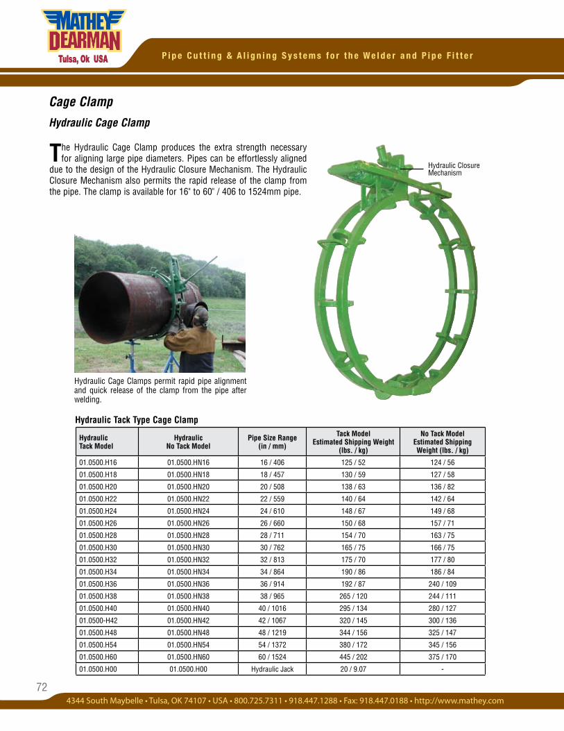
72
P i p e C u t t i n g & A l i g n i n g S y s t e m s f o r t h e W e l d e r a n d P i p e F i t t e r
Cage Clamp
Hydraulic Cage Clamp
The Hydraulic Cage Clamp produces the extra strength necessary for aligning large pipe diameters. Pipes can be effortlessly aligned
due to the design of the Hydraulic Closure Mechanism. The Hydraulic Closure Mechanism also permits the rapid release of the clamp from the pipe. The clamp is available for 16" to 60" / 406 to 1524mm pipe.
Hydraulic Tack Type Cage Clamp
Hydraulic Cage Clamps permit rapid pipe alignment and quick release of the clamp from the pipe after welding.
Hydraulic Closure Mechanism
Hydraulic Tack Model
Hydraulic No Tack Model
Pipe Size Range (in / mm)
Tack Model Estimated Shipping Weight
(lbs. / kg)
No Tack Model Estimated Shipping Weight (lbs. / kg)
01.0500.H16 01.0500.HN16 16 / 406 125 / 52 124 / 56
01.0500.H18 01.0500.HN18 18 / 457 130 / 59 127 / 58
01.0500.H20 01.0500.HN20 20 / 508 138 / 63 136 / 82
01.0500.H22 01.0500.HN22 22 / 559 140 / 64 142 / 64
01.0500.H24 01.0500.HN24 24 / 610 148 / 67 149 / 68
01.0500.H26 01.0500.HN26 26 / 660 150 / 68 157 / 71
01.0500.H28 01.0500.HN28 28 / 711 154 / 70 163 / 75
01.0500.H30 01.0500.HN30 30 / 762 165 / 75 166 / 75
01.0500.H32 01.0500.HN32 32 / 813 175 / 70 177 / 80
01.0500.H34 01.0500.HN34 34 / 864 190 / 86 186 / 84
01.0500.H36 01.0500.HN36 36 / 914 192 / 87 240 / 109
01.0500.H38 01.0500.HN38 38 / 965 265 / 120 244 / 111
01.0500.H40 01.0500.HN40 40 / 1016 295 / 134 280 / 127
01.0500-H42 01.0500.HN42 42 / 1067 320 / 145 300 / 136
01.0500.H48 01.0500.HN48 48 / 1219 344 / 156 325 / 147
01.0500.H54 01.0500.HN54 54 / 1372 380 / 172 345 / 156
01.0500.H60 01.0500.HN60 60 / 1524 445 / 202 375 / 170
01.0500.H00 01.0500.H00 Hydraulic Jack 20 / 9.07 -
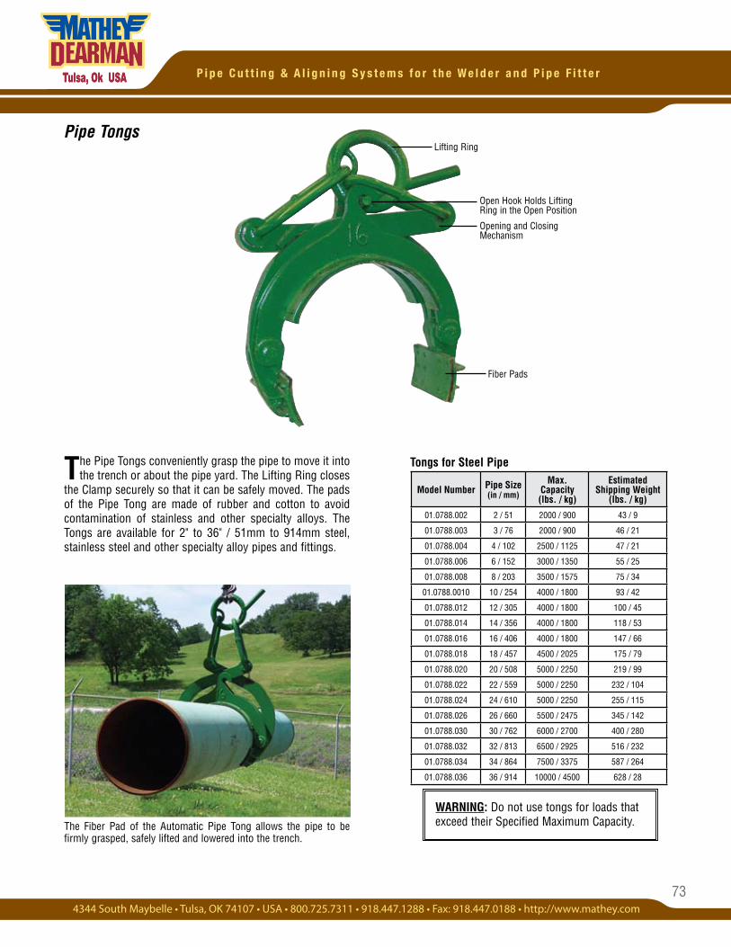
73
P i p e C u t t i n g & A l i g n i n g S y s t e m s f o r t h e W e l d e r a n d P i p e F i t t e r
Pipe Tongs
WARNING: Do not use tongs for loads that exceed their Specified Maximum Capacity.
Tongs for Steel Pipe
The Fiber Pad of the Automatic Pipe Tong allows the pipe to be firmly grasped, safely lifted and lowered into the trench.
The Pipe Tongs conveniently grasp the pipe to move it into the trench or about the pipe yard. The Lifting Ring closes
the Clamp securely so that it can be safely moved. The pads of the Pipe Tong are made of rubber and cotton to avoid contamination of stainless and other specialty alloys. The Tongs are available for 2" to 36" / 51mm to 914mm steel, stainless steel and other specialty alloy pipes and fittings.
Fiber Pads
Lifting Ring
Model Number Pipe Size(in / mm)
Max. Capacity(lbs. / kg)
EstimatedShipping Weight
(lbs. / kg)
01.0788.002 2 / 51 2000 / 900 43 / 9
01.0788.003 3 / 76 2000 / 900 46 / 21
01.0788.004 4 / 102 2500 / 1125 47 / 21
01.0788.006 6 / 152 3000 / 1350 55 / 25
01.0788.008 8 / 203 3500 / 1575 75 / 34
01.0788.0010 10 / 254 4000 / 1800 93 / 42
01.0788.012 12 / 305 4000 / 1800 100 / 45
01.0788.014 14 / 356 4000 / 1800 118 / 53
01.0788.016 16 / 406 4000 / 1800 147 / 66
01.0788.018 18 / 457 4500 / 2025 175 / 79
01.0788.020 20 / 508 5000 / 2250 219 / 99
01.0788.022 22 / 559 5000 / 2250 232 / 104
01.0788.024 24 / 610 5000 / 2250 255 / 115
01.0788.026 26 / 660 5500 / 2475 345 / 142
01.0788.030 30 / 762 6000 / 2700 400 / 280
01.0788.032 32 / 813 6500 / 2925 516 / 232
01.0788.034 34 / 864 7500 / 3375 587 / 264
01.0788.036 36 / 914 10000 / 4500 628 / 28
Open Hook Holds Lifting Ring in the Open Position
Opening and Closing Mechanism
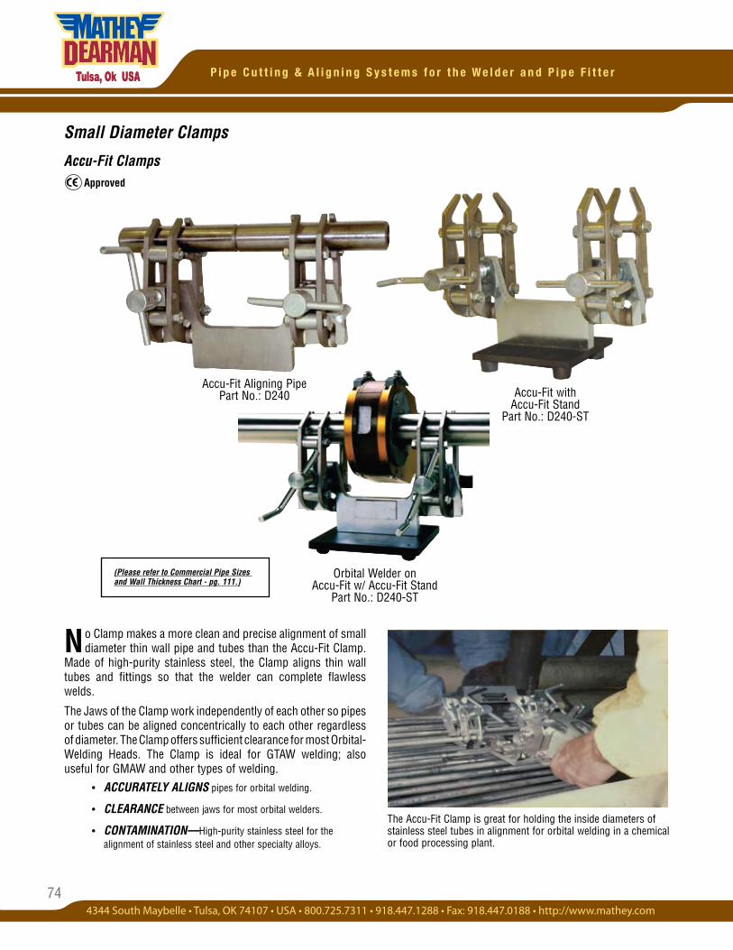
74
P i p e C u t t i n g & A l i g n i n g S y s t e m s f o r t h e W e l d e r a n d P i p e F i t t e r
Small Diameter Clamps
Accu-Fit Clamps
Accu-Fit with Accu-Fit Stand
Part No.: D240-ST
No Clamp makes a more clean and precise alignment of small diameter thin wall pipe and tubes than the Accu-Fit Clamp.
Made of high-purity stainless steel, the Clamp aligns thin wall tubes and fittings so that the welder can complete flawless welds.
The Jaws of the Clamp work independently of each other so pipes or tubes can be aligned concentrically to each other regardless of diameter. The Clamp offers sufficient clearance for most Orbital- Welding Heads. The Clamp is ideal for GTAW welding; also useful for GMAW and other types of welding. • ACCURATELY ALIGNS pipes for orbital welding.
• CLEARANCE between jaws for most orbital welders.
• CONTAMINATION—High-purity stainless steel for the alignment of stainless steel and other specialty alloys.
The Accu-Fit Clamp is great for holding the inside diameters of stainless steel tubes in alignment for orbital welding in a chemical or food processing plant.
Accu-Fit Aligning Pipe Part No.: D240
Orbital Welder on Accu-Fit w/ Accu-Fit Stand
Part No.: D240-ST
Approved
(Please refer to Commercial Pipe Sizes and Wall Thickness Chart - pg. 111.)
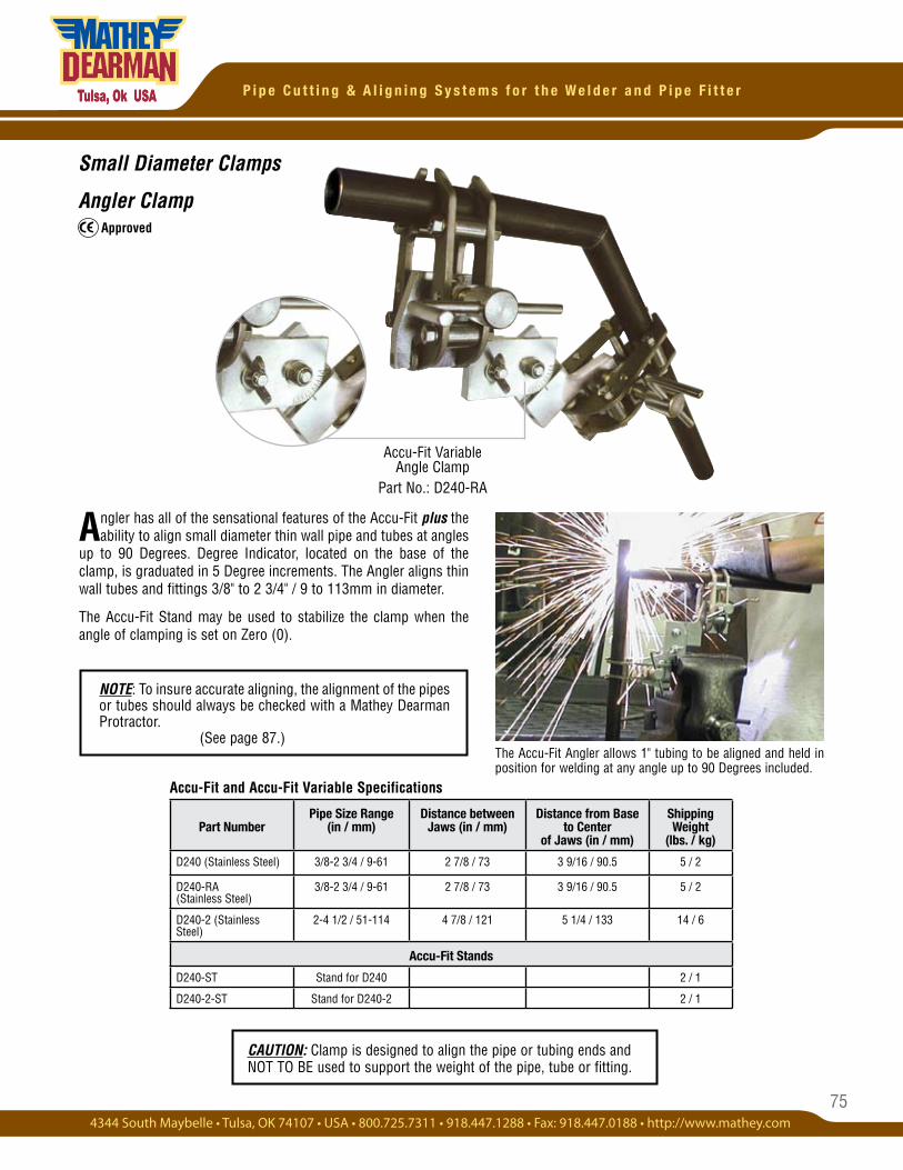
75
P i p e C u t t i n g & A l i g n i n g S y s t e m s f o r t h e W e l d e r a n d P i p e F i t t e r
Small Diameter Clamps
Angler Clamp
Angler has all of the sensational features of the Accu-Fit plus the ability to align small diameter thin wall pipe and tubes at angles
up to 90 Degrees. Degree Indicator, located on the base of the clamp, is graduated in 5 Degree increments. The Angler aligns thin wall tubes and fittings 3/8" to 2 3/4" / 9 to 113mm in diameter.
The Accu-Fit Stand may be used to stabilize the clamp when the angle of clamping is set on Zero (0).
Accu-Fit Variable Angle Clamp
Part No.: D240-RA
The Accu-Fit Angler allows 1" tubing to be aligned and held in position for welding at any angle up to 90 Degrees included.
Accu-Fit and Accu-Fit Variable Specifications
CAUTION: Clamp is designed to align the pipe or tubing ends and NOT TO BE used to support the weight of the pipe, tube or fitting.
Approved
Part NumberPipe Size Range
(in / mm)Distance between
Jaws (in / mm)Distance from Base
to Center of Jaws (in / mm)
Shipping Weight
(lbs. / kg)
D240 (Stainless Steel) 3/8-2 3/4 / 9-61 2 7/8 / 73 3 9/16 / 90.5 5 / 2
D240-RA (Stainless Steel)
3/8-2 3/4 / 9-61 2 7/8 / 73 3 9/16 / 90.5 5 / 2
D240-2 (Stainless Steel)
2-4 1/2 / 51-114 4 7/8 / 121 5 1/4 / 133 14 / 6
Accu-Fit Stands
D240-ST Stand for D240 2 / 1
D240-2-ST Stand for D240-2 2 / 1
NOTE: To insure accurate aligning, the alignment of the pipes or tubes should always be checked with a Mathey Dearman Protractor.
(See page 87.)
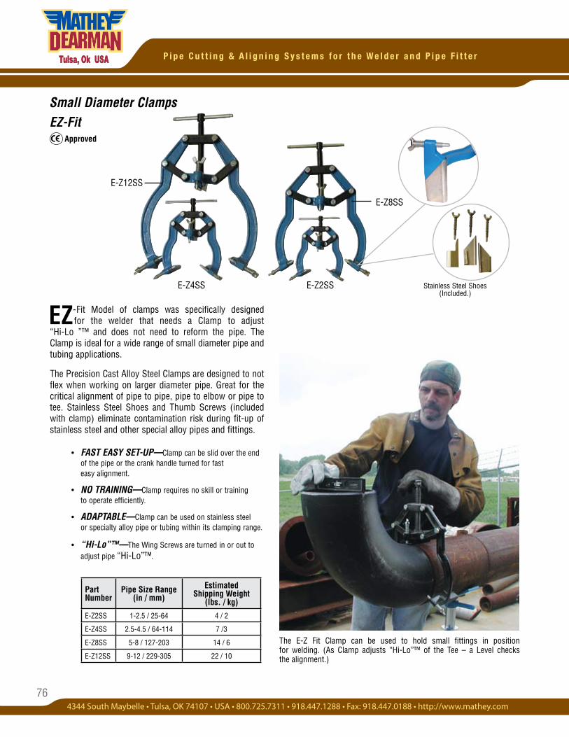
76
P i p e C u t t i n g & A l i g n i n g S y s t e m s f o r t h e W e l d e r a n d P i p e F i t t e r
Small Diameter ClampsEZ-Fit
E-Z4SS
E-Z12SS
E-Z2SS
Approved
Stainless Steel Shoes (Included.)
E-Z8SS
-Fit Model of clamps was specifically designed for the welder that needs a Clamp to adjust “Hi-Lo ”™ and does not need to reform the pipe. The Clamp is ideal for a wide range of small diameter pipe and tubing applications.
The Precision Cast Alloy Steel Clamps are designed to not flex when working on larger diameter pipe. Great for the critical alignment of pipe to pipe, pipe to elbow or pipe to tee. Stainless Steel Shoes and Thumb Screws (included with clamp) eliminate contamination risk during fit-up of stainless steel and other special alloy pipes and fittings.
• FAST EASY SET-UP—Clamp can be slid over the end of the pipe or the crank handle turned for fast easy alignment.
• NO TRAINING—Clamp requires no skill or training to operate efficiently.
• ADAPTABLE—Clamp can be used on stainless steel or specialty alloy pipe or tubing within its clamping range.
• “Hi-Lo”™—The Wing Screws are turned in or out to adjust pipe “Hi-Lo”™.
EZ
Part Number
Pipe Size Range (in / mm)
Estimated Shipping Weight
(lbs. / kg)
E-Z2SS 1-2.5 / 25-64 4 / 2
E-Z4SS 2.5-4.5 / 64-114 7 /3
E-Z8SS 5-8 / 127-203 14 / 6
E-Z12SS 9-12 / 229-305 22 / 10
The E-Z Fit Clamp can be used to hold small fittings in position for welding. (As Clamp adjusts “Hi-Lo”™ of the Tee – a Level checks the alignment.)
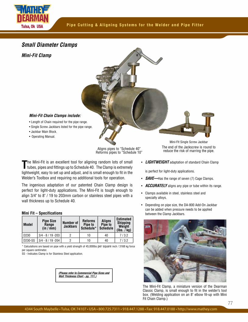
77
P i p e C u t t i n g & A l i g n i n g S y s t e m s f o r t h e W e l d e r a n d P i p e F i t t e r
Aligns pipes to “Schedule 40” Reforms pipes to “Schedule 10”
Small Diameter Clamps
Mini-Fit Clamp
Mini Fit – Specifications
* Calculations are based on pipe with a yield strength of 45,000lbs per square inch / 3168 kg force per square centimeter. SS - Indicates Clamp is for Stainless Steel application.
Mini-Fit Single Screw Jackbar
The end of the Jackscrew is round to reduce the risk of marring the pipe.
The Mini-Fit is an excellent tool for aligning random lots of small tubes, pipes and fittings up to Schedule 40. The Clamp is extremely
lightweight, easy to set up and adjust, and is small enough to fit in the Welder’s Toolbox and requiring no additional tools for operation.
The ingenious adaptation of our patented Chain Clamp design is perfect for light-duty applications. The Mini-Fit is tough enough to align 3/4" to 8" / 19 to 203mm carbon or stainless steel pipes with a wall thickness up to Schedule 40.
• LIGHTWEIGHT adaptation of standard Chain Clamp is perfect for light-duty applications.
• SAVE—Has the range of seven (7) Cage Clamps.
• ACCURATELY aligns any pipe or tube within its range.
• Clamps available in steel, stainless steel and specialty alloys.
• Depending on pipe size, the DA-800 Add-On Jackbar can be added when pressure needs to be applied between the Clamp Jackbars.
Mini-Fit Chain Clamps include:• Length of Chain required for the pipe range.• Single Screw Jackbars listed for the pipe range. • Jackbar Main Block.• Operating Manual.
The Mini-Fit Clamp, a miniature version of the Dearman Classic Clamp, is small enough to fit in the welder’s tool box. (Welding application on an 8" elbow fit-up with Mini Fit Chain Clamp.)
(Please refer to Commercial Pipe Sizes and Wall Thickness Chart - pg. 111.)
ModelPipe Size
Range(in / mm)
Number of Jackbars
Reforms Pipe to
Schedule*
Aligns Pipe to
Schedule
EstimatedShipping Weight
(lbs. / kg)D230 3/4 - 8 / 19 -203 2 10 40 7 / 3.2
D230-SS 3/4 - 8 / 19 -204 2 10 40 7 / 3.2
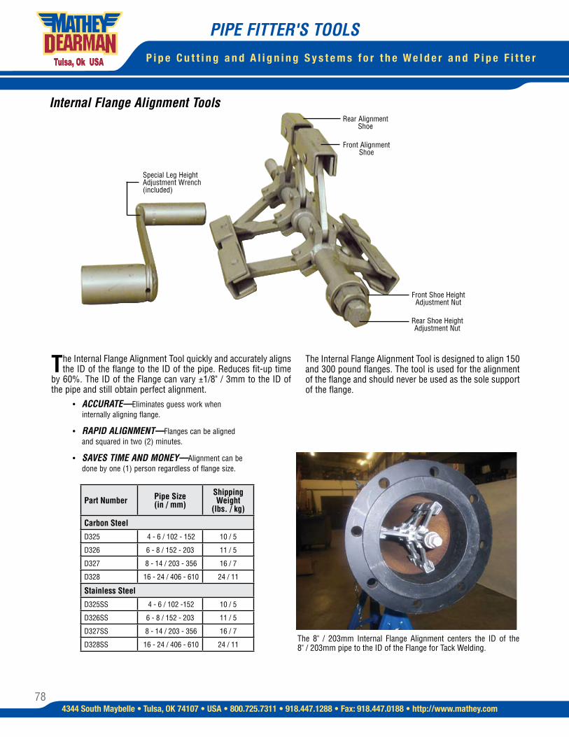
78
P i p e C u t t i n g a n d A l i g n i n g S y s t e m s f o r t h e W e l d e r a n d P i p e F i t t e r
4344 South Maybelle • Tulsa, OK 74107 • USA • 800.725.7311 • 918.447.1288 • Fax: 918.447.0188 • http://www.mathey.com
Internal Flange Alignment Tools
The Internal Flange Alignment Tool quickly and accurately aligns the ID of the flange to the ID of the pipe. Reduces fit-up time
by 60%. The ID of the Flange can vary ±1/8" / 3mm to the ID of the pipe and still obtain perfect alignment. • ACCURATE—Eliminates guess work when internally aligning flange.
• RAPID ALIGNMENT—Flanges can be aligned and squared in two (2) minutes.
• SAVES TIME AND MONEY—Alignment can be done by one (1) person regardless of flange size.
Special Leg Height Adjustment Wrench (included)
Front Shoe Height Adjustment Nut
Rear Shoe Height Adjustment Nut
Rear Alignment Shoe
Front Alignment Shoe
PIPE FITTER'S TOOLS
Part Number Pipe Size (in / mm)
Shipping Weight
(lbs. / kg)
Carbon Steel
D325 4 - 6 / 102 - 152 10 / 5
D326 6 - 8 / 152 - 203 11 / 5
D327 8 - 14 / 203 - 356 16 / 7
D328 16 - 24 / 406 - 610 24 / 11
Stainless Steel
D325SS 4 - 6 / 102 -152 10 / 5
D326SS 6 - 8 / 152 - 203 11 / 5
D327SS 8 - 14 / 203 - 356 16 / 7
D328SS 16 - 24 / 406 - 610 24 / 11The 8" / 203mm Internal Flange Alignment centers the ID of the 8" / 203mm pipe to the ID of the Flange for Tack Welding.
The Internal Flange Alignment Tool is designed to align 150 and 300 pound flanges. The tool is used for the alignment of the flange and should never be used as the sole support of the flange.
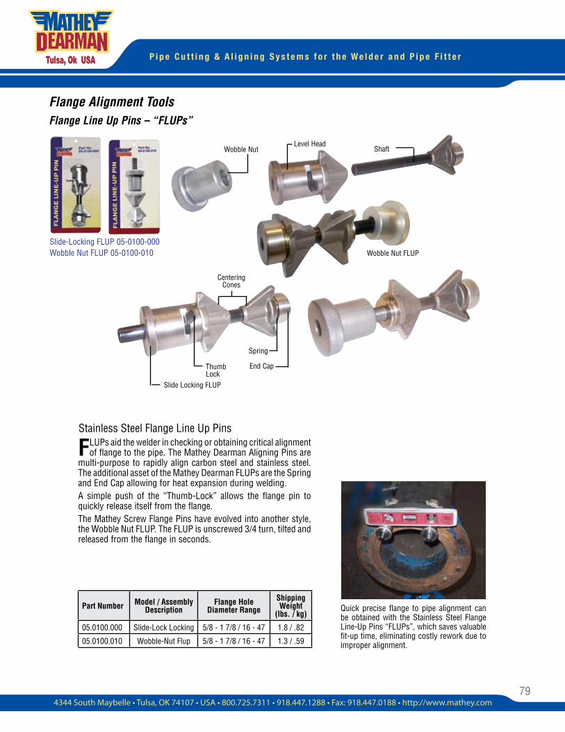
79
P i p e C u t t i n g & A l i g n i n g S y s t e m s f o r t h e W e l d e r a n d P i p e F i t t e r
Flange Alignment ToolsFlange Line Up Pins – “FLUPs”
FLUPs aid the welder in checking or obtaining critical alignment of flange to the pipe. The Mathey Dearman Aligning Pins are
multi-purpose to rapidly align carbon steel and stainless steel. The additional asset of the Mathey Dearman FLUPs are the Spring and End Cap allowing for heat expansion during welding.A simple push of the “Thumb-Lock” allows the flange pin to quickly release itself from the flange.The Mathey Screw Flange Pins have evolved into another style, the Wobble Nut FLUP. The FLUP is unscrewed 3/4 turn, tilted and released from the flange in seconds.
Quick precise flange to pipe alignment can be obtained with the Stainless Steel Flange Line-Up Pins “FLUPs”, which saves valuable fit-up time, eliminating costly rework due to improper alignment.
Centering Cones
Wobble Nut FLUP
Wobble Nut Shaft
Thumb Lock
Slide Locking FLUP
Level Head
Spring
Slide-Locking FLUP 05-0100-000 Wobble Nut FLUP 05-0100-010
Part Number Model / Assembly Description
Flange Hole Diameter Range
Shipping Weight
(lbs. / kg)
05.0100.000 Slide-Lock Locking 5/8 - 1 7/8 / 16 - 47 1.8 / .82
05.0100.010 Wobble-Nut Flup 5/8 - 1 7/8 / 16 - 47 1.3 / .59
Stainless Steel Flange Line Up Pins
End Cap
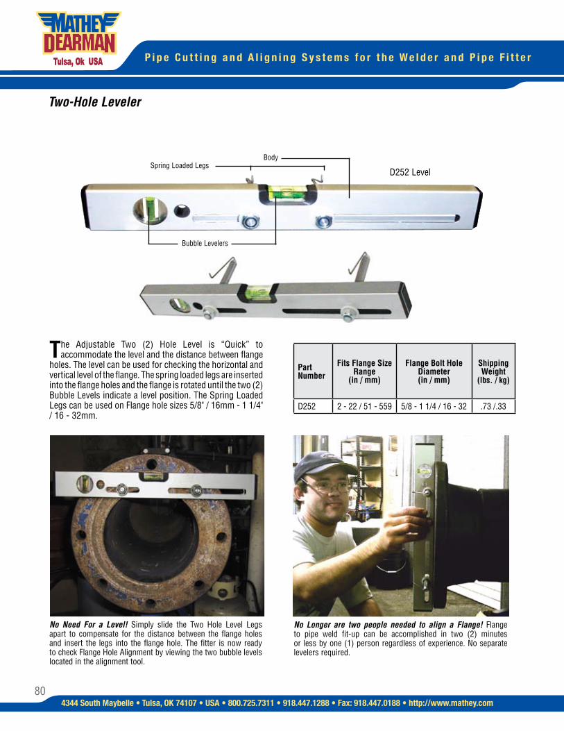
80
P i p e C u t t i n g a n d A l i g n i n g S y s t e m s f o r t h e W e l d e r a n d P i p e F i t t e r
4344 South Maybelle • Tulsa, OK 74107 • USA • 800.725.7311 • 918.447.1288 • Fax: 918.447.0188 • http://www.mathey.com
No Need For a Level! Simply slide the Two Hole Level Legs apart to compensate for the distance between the flange holes and insert the legs into the flange hole. The fitter is now ready to check Flange Hole Alignment by viewing the two bubble levels located in the alignment tool.
No Longer are two people needed to align a Flange! Flange to pipe weld fit-up can be accomplished in two (2) minutes or less by one (1) person regardless of experience. No separate levelers required.
The Adjustable Two (2) Hole Level is “Quick” to accommodate the level and the distance between flange
holes. The level can be used for checking the horizontal and vertical level of the flange. The spring loaded legs are inserted into the flange holes and the flange is rotated until the two (2) Bubble Levels indicate a level position. The Spring Loaded Legs can be used on Flange hole sizes 5/8" / 16mm - 1 1/4" / 16 - 32mm.
D252 Level
Two-Hole Leveler
BodySpring Loaded Legs
Bubble Levelers
Part Number
Fits Flange Size Range
(in / mm)
Flange Bolt Hole Diameter (in / mm)
Shipping Weight
(lbs. / kg)
D252 2 - 22 / 51 - 559 5/8 - 1 1/4 / 16 - 32 .73 /.33
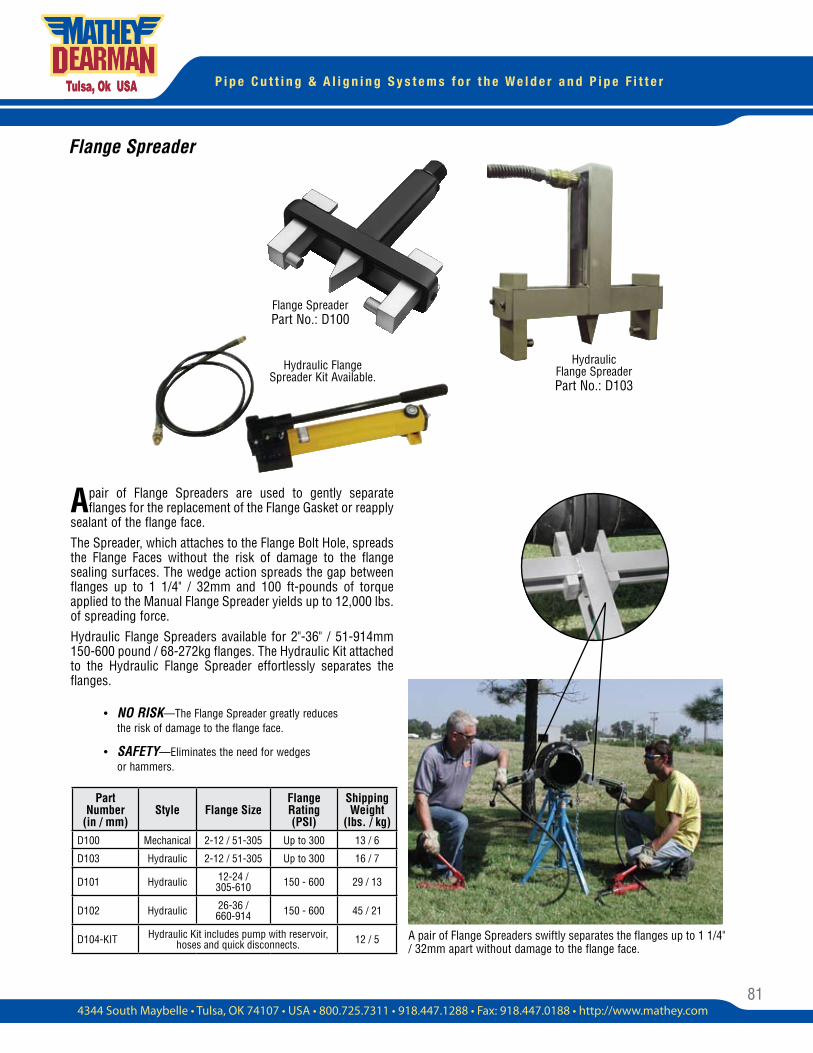
81
P i p e C u t t i n g & A l i g n i n g S y s t e m s f o r t h e W e l d e r a n d P i p e F i t t e r
Flange Spreader
A pair of Flange Spreaders are used to gently separate flanges for the replacement of the Flange Gasket or reapply
sealant of the flange face. The Spreader, which attaches to the Flange Bolt Hole, spreads the Flange Faces without the risk of damage to the flange sealing surfaces. The wedge action spreads the gap between flanges up to 1 1/4" / 32mm and 100 ft-pounds of torque applied to the Manual Flange Spreader yields up to 12,000 lbs. of spreading force. Hydraulic Flange Spreaders available for 2"-36" / 51-914mm 150-600 pound / 68-272kg flanges. The Hydraulic Kit attached to the Hydraulic Flange Spreader effortlessly separates the flanges.
A pair of Flange Spreaders swiftly separates the flanges up to 1 1/4" / 32mm apart without damage to the flange face.
Hydraulic Flange Spreader Part No.: D103
Hydraulic Flange Spreader Kit Available.
• NO RISK—The Flange Spreader greatly reduces the risk of damage to the flange face.
• SAFETY—Eliminates the need for wedges or hammers.
Flange Spreader Part No.: D100
Part Number
(in / mm) Style Flange Size
Flange Rating (PSI)
Shipping Weight
(lbs. / kg)D100 Mechanical 2-12 / 51-305 Up to 300 13 / 6
D103 Hydraulic 2-12 / 51-305 Up to 300 16 / 7
D101 Hydraulic 12-24 / 305-610 150 - 600 29 / 13
D102 Hydraulic 26-36 / 660-914 150 - 600 45 / 21
D104-KIT Hydraulic Kit includes pump with reservoir, hoses and quick disconnects. 12 / 5
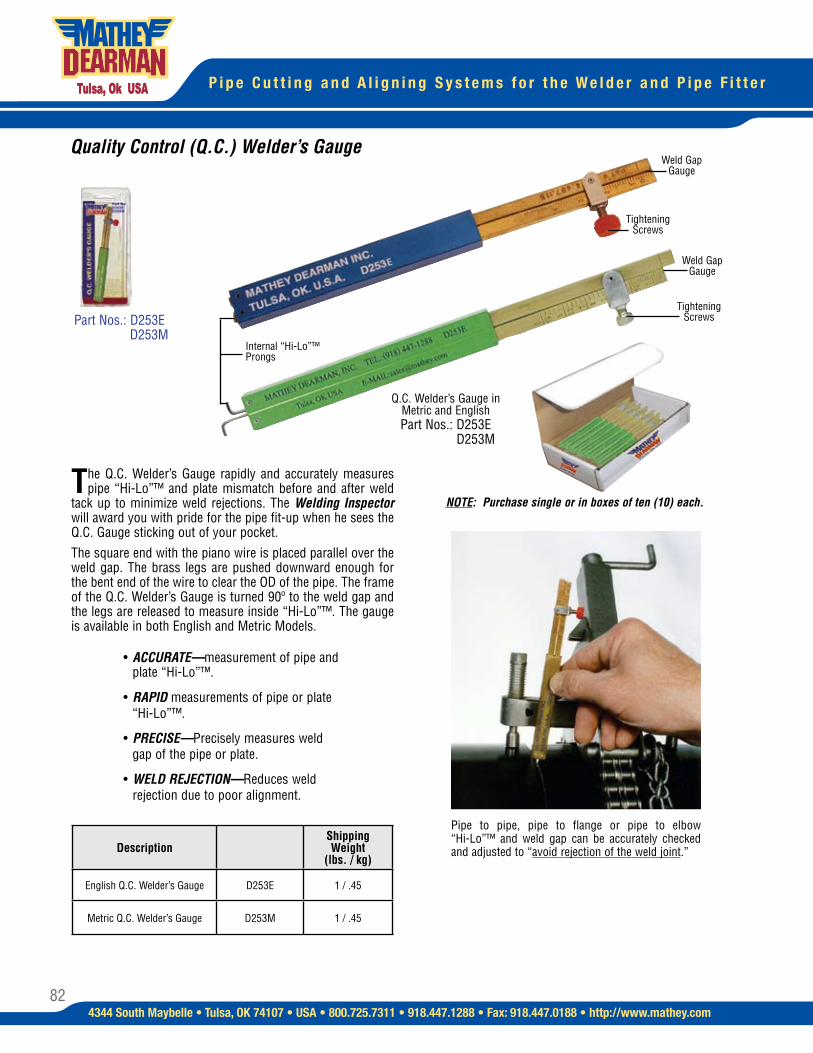
82
P i p e C u t t i n g a n d A l i g n i n g S y s t e m s f o r t h e W e l d e r a n d P i p e F i t t e r
4344 South Maybelle • Tulsa, OK 74107 • USA • 800.725.7311 • 918.447.1288 • Fax: 918.447.0188 • http://www.mathey.com
Pipe to pipe, pipe to flange or pipe to elbow “Hi-Lo”™ and weld gap can be accurately checked and adjusted to “avoid rejection of the weld joint.”
Q.C. Welder’s Gauge in Metric and English Part Nos.: D253E
D253M
Internal “Hi-Lo”™ Prongs
Tightening Screws
The Q.C. Welder’s Gauge rapidly and accurately measures pipe “Hi-Lo”™ and plate mismatch before and after weld
tack up to minimize weld rejections. The Welding Inspector will award you with pride for the pipe fit-up when he sees the Q.C. Gauge sticking out of your pocket.The square end with the piano wire is placed parallel over the weld gap. The brass legs are pushed downward enough for the bent end of the wire to clear the OD of the pipe. The frame of the Q.C. Welder’s Gauge is turned 90º to the weld gap and the legs are released to measure inside “Hi-Lo”™. The gauge is available in both English and Metric Models.
• ACCURATE—measurement of pipe and plate “Hi-Lo”™.
• RAPID measurements of pipe or plate “Hi-Lo”™.
• PRECISE—Precisely measures weld gap of the pipe or plate.
• WELD REJECTION—Reduces weld rejection due to poor alignment.
Part Nos.: D253E D253M
Quality Control (Q.C.) Welder’s Gauge
Description Shipping Weight
(lbs. / kg)
English Q.C. Welder’s Gauge D253E 1 / .45
Metric Q.C. Welder’s Gauge D253M 1 / .45
Weld Gap Gauge
Weld Gap Gauge
Tightening Screws
NOTE: Purchase single or in boxes of ten (10) each.
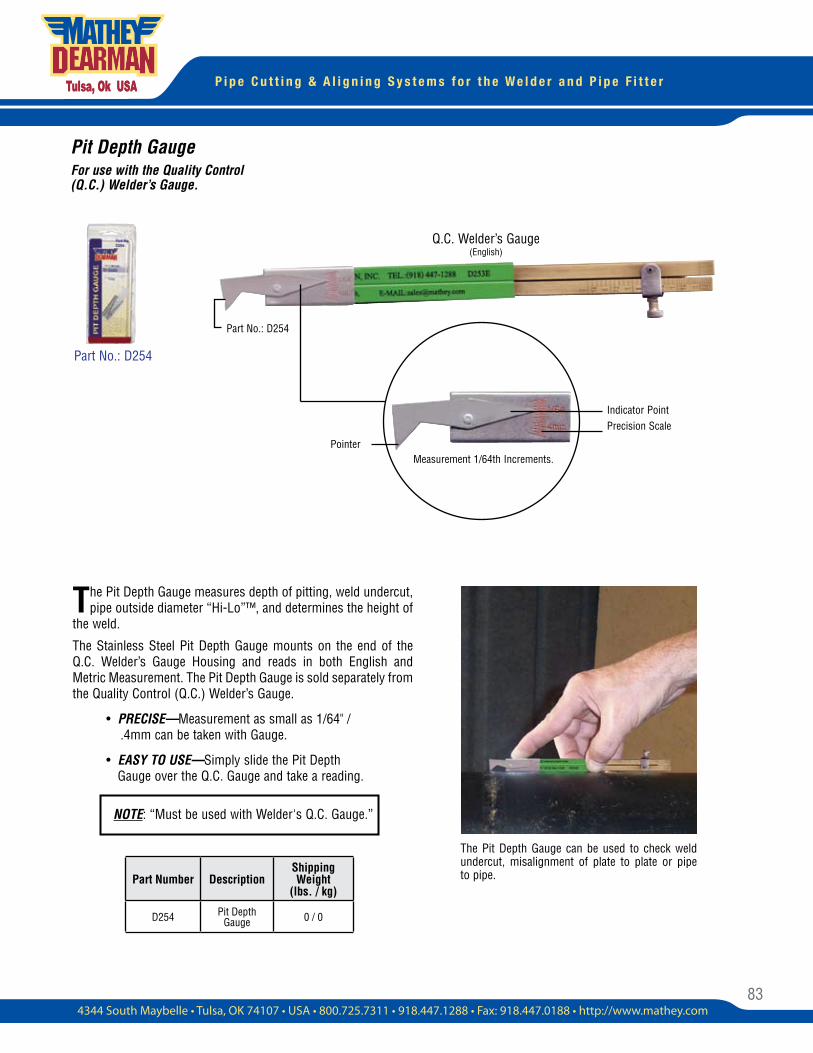
83
P i p e C u t t i n g & A l i g n i n g S y s t e m s f o r t h e W e l d e r a n d P i p e F i t t e r
The Pit Depth Gauge measures depth of pitting, weld undercut, pipe outside diameter “Hi-Lo”™, and determines the height of
the weld.
The Stainless Steel Pit Depth Gauge mounts on the end of the Q.C. Welder’s Gauge Housing and reads in both English and Metric Measurement. The Pit Depth Gauge is sold separately from the Quality Control (Q.C.) Welder’s Gauge.
• PRECISE—Measurement as small as 1/64" / .4mm can be taken with Gauge.
• EASY TO USE—Simply slide the Pit Depth Gauge over the Q.C. Gauge and take a reading.
Pit Depth GaugeFor use with the Quality Control (Q.C.) Welder’s Gauge.
The Pit Depth Gauge can be used to check weld undercut, misalignment of plate to plate or pipe to pipe.
Q.C. Welder’s Gauge (English)
Measurement 1/64th Increments.
Part No.: D254
Pointer
Indicator PointPrecision Scale
Part No.: D254
Part Number DescriptionShipping Weight
(lbs. / kg)
D254 Pit Depth Gauge 0 / 0
NOTE: “Must be used with Welder's Q.C. Gauge.”
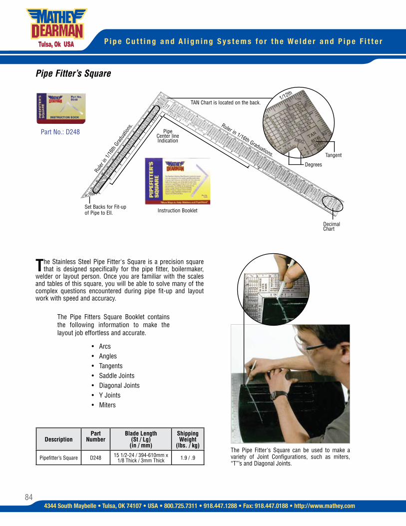
84
P i p e C u t t i n g a n d A l i g n i n g S y s t e m s f o r t h e W e l d e r a n d P i p e F i t t e r
4344 South Maybelle • Tulsa, OK 74107 • USA • 800.725.7311 • 918.447.1288 • Fax: 918.447.0188 • http://www.mathey.com
Instruction Booklet
Degrees
1/12th
Tangent
Pipe Center line Indication
Ruler
in 1
/16t
h Gr
adua
tions
. Ruler in 1/16th Graduations.
Set Backs for Fit-up of Pipe to Ell.
TAN Chart is located on the back.
Decimal Chart
The Stainless Steel Pipe Fitter's Square is a precision square that is designed specifically for the pipe fitter, boilermaker,
welder or layout person. Once you are familiar with the scales and tables of this square, you will be able to solve many of the complex questions encountered during pipe fit-up and layout work with speed and accuracy.
Pipe Fitter’s Square
The Pipe Fitters Square Booklet contains the following information to make the layout job effortless and accurate.
• Arcs • Angles • Tangents • Saddle Joints • Diagonal Joints • Y Joints • Miters
The Pipe Fitter's Square can be used to make a variety of Joint Configurations, such as miters, “T”’s and Diagonal Joints.
Part No.: D248
DescriptionPart
NumberBlade Length
(St / Lg)(in / mm)
Shipping Weight
(lbs. / kg)
Pipefitter’s Square D248 15 1/2-24 / 394-610mm x 1/8 Thick / 3mm Thick 1.9 / .9
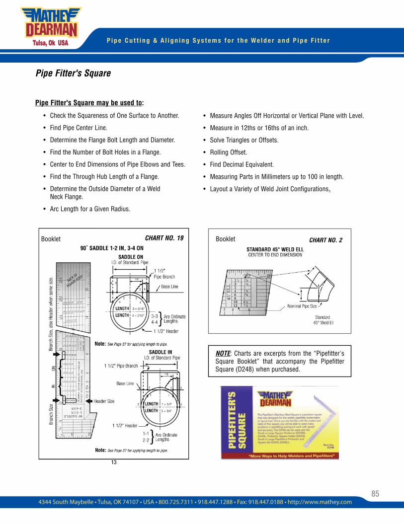
85
P i p e C u t t i n g & A l i g n i n g S y s t e m s f o r t h e W e l d e r a n d P i p e F i t t e r
Pipe Fitter's Square
Pipe Fitter's Square may be used to:
• Check the Squareness of One Surface to Another.
• Find Pipe Center Line.
• Determine the Flange Bolt Length and Diameter.
• Find the Number of Bolt Holes in a Flange.
• Center to End Dimensions of Pipe Elbows and Tees.
• Find the Through Hub Length of a Flange.
• Determine the Outside Diameter of a Weld Neck Flange.
• Arc Length for a Given Radius.
• Measure Angles Off Horizontal or Vertical Plane with Level.
• Measure in 12ths or 16ths of an inch.
• Solve Triangles or Offsets.
• Rolling Offset.
• Find Decimal Equivalent.
• Measuring Parts in Millimeters up to 100 in length.
• Layout a Variety of Weld Joint Configurations.
NOTE: Charts are excerpts from the “Pipefitter's Square Booklet” that accompany the Pipefitter Square (D248) when purchased.
Booklet Booklet
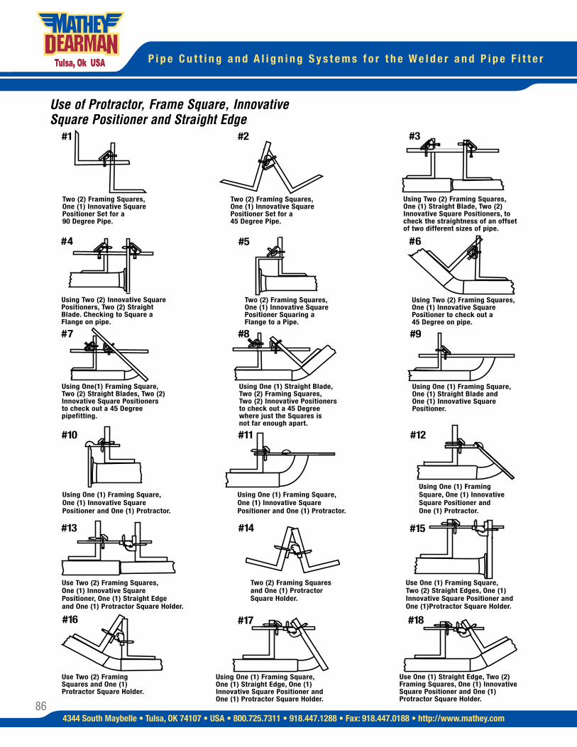
86
P i p e C u t t i n g a n d A l i g n i n g S y s t e m s f o r t h e W e l d e r a n d P i p e F i t t e r
4344 South Maybelle • Tulsa, OK 74107 • USA • 800.725.7311 • 918.447.1288 • Fax: 918.447.0188 • http://www.mathey.com
Use of Protractor, Frame Square, Innovative Square Positioner and Straight Edge
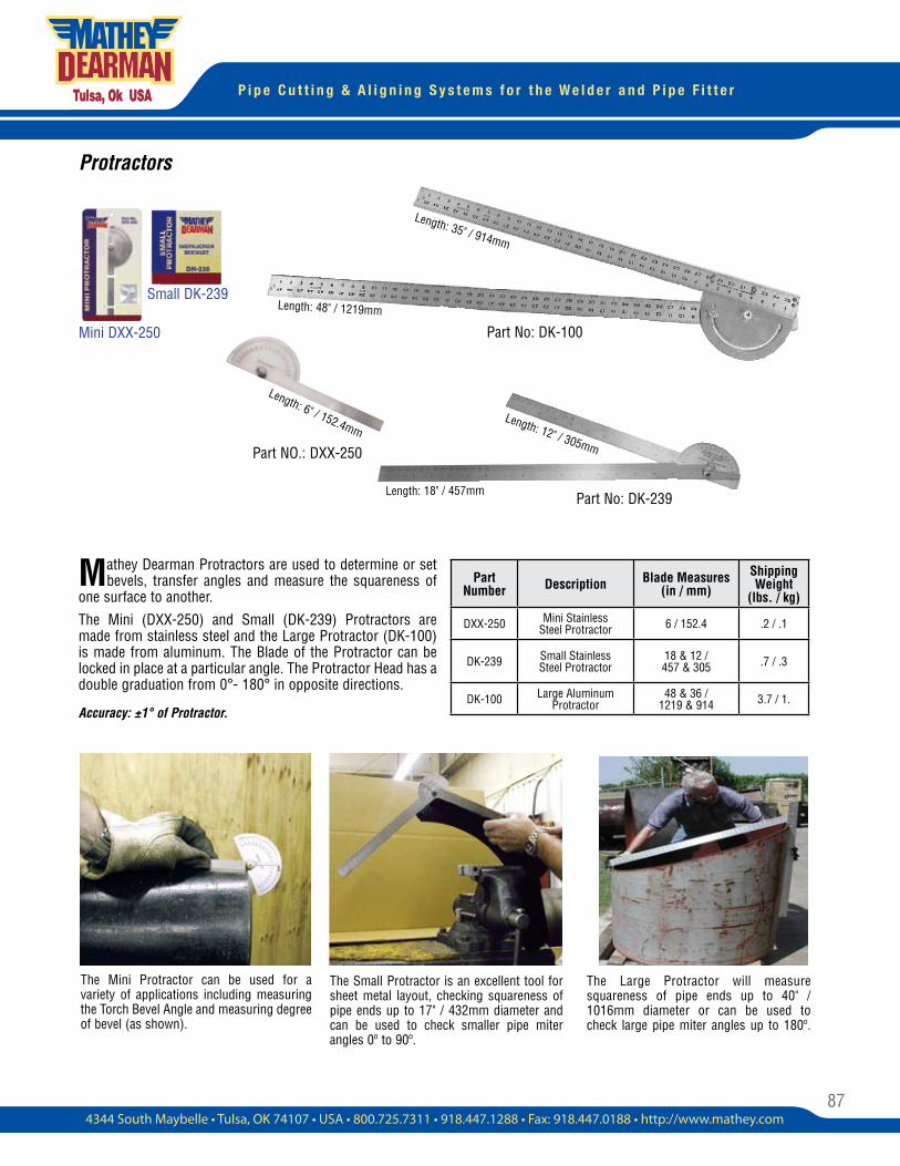
87
P i p e C u t t i n g & A l i g n i n g S y s t e m s f o r t h e W e l d e r a n d P i p e F i t t e r
Mini DXX-250
Small DK-239
Part No: DK-100
Part No: DK-239
Protractors
Mathey Dearman Protractors are used to determine or set bevels, transfer angles and measure the squareness of
one surface to another. The Mini (DXX-250) and Small (DK-239) Protractors are made from stainless steel and the Large Protractor (DK-100) is made from aluminum. The Blade of the Protractor can be locked in place at a particular angle. The Protractor Head has a double graduation from 0°- 180° in opposite directions.
Accuracy: ±1° of Protractor.
The Mini Protractor can be used for a variety of applications including measuring the Torch Bevel Angle and measuring degree of bevel (as shown).
The Small Protractor is an excellent tool for sheet metal layout, checking squareness of pipe ends up to 17" / 432mm diameter and can be used to check smaller pipe miter angles 0º to 90º.
The Large Protractor will measure squareness of pipe ends up to 40" / 1016mm diameter or can be used to check large pipe miter angles up to 180º.
Length: 6" / 152.4mm
Length: 48" / 1219mm
Length: 35" / 914mm
Length: 18" / 457mm
Length: 12" / 305mmPart NO.: DXX-250
Part Number Description Blade Measures
(in / mm)Shipping Weight
(lbs. / kg)
DXX-250 Mini Stainless Steel Protractor 6 / 152.4 .2 / .1
DK-239 Small Stainless Steel Protractor
18 & 12 / 457 & 305 .7 / .3
DK-100 Large Aluminum Protractor
48 & 36 / 1219 & 914 3.7 / 1.
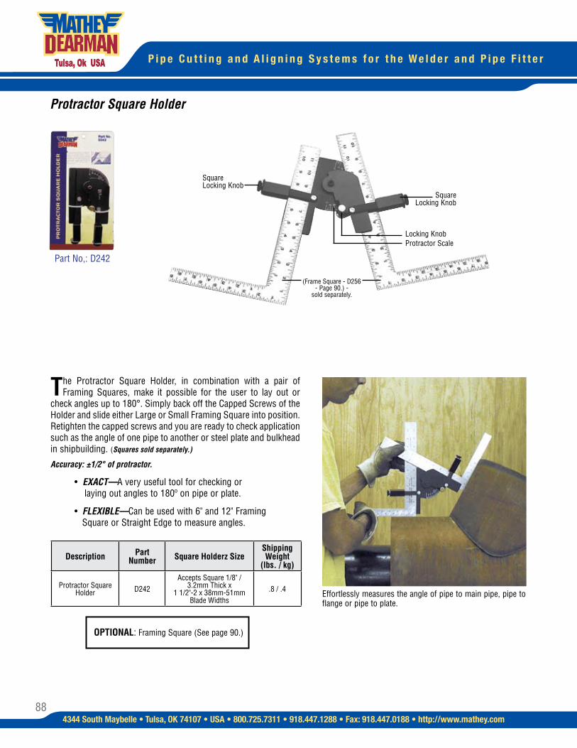
88
P i p e C u t t i n g a n d A l i g n i n g S y s t e m s f o r t h e W e l d e r a n d P i p e F i t t e r
4344 South Maybelle • Tulsa, OK 74107 • USA • 800.725.7311 • 918.447.1288 • Fax: 918.447.0188 • http://www.mathey.com
Protractor Square Holder
The Protractor Square Holder, in combination with a pair of Framing Squares, make it possible for the user to lay out or
check angles up to 180°. Simply back off the Capped Screws of the Holder and slide either Large or Small Framing Square into position. Retighten the capped screws and you are ready to check application such as the angle of one pipe to another or steel plate and bulkhead in shipbuilding. (Squares sold separately.)
Accuracy: ±1/2° of protractor.
• EXACT—A very useful tool for checking or laying out angles to 180º on pipe or plate.
• FLEXIBLE—Can be used with 6" and 12" Framing Square or Straight Edge to measure angles.
Effortlessly measures the angle of pipe to main pipe, pipe to flange or pipe to plate.
Square Locking Knob
Square Locking Knob
Locking KnobProtractor Scale
Part No,: D242
(Frame Square - D256 - Page 90.) -
sold separately.
Description Part Number Square Holderz Size
Shipping Weight
(lbs. / kg)
Protractor Square Holder D242
Accepts Square 1/8" / 3.2mm Thick x
1 1/2"-2 x 38mm-51mm Blade Widths
.8 / .4
OPTIONAL: Framing Square (See page 90.)
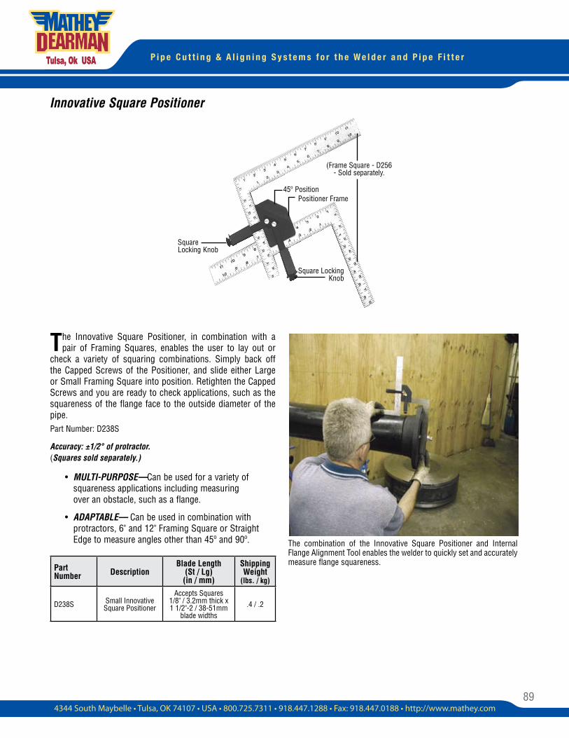
89
P i p e C u t t i n g & A l i g n i n g S y s t e m s f o r t h e W e l d e r a n d P i p e F i t t e r
Innovative Square Positioner
The Innovative Square Positioner, in combination with a pair of Framing Squares, enables the user to lay out or
check a variety of squaring combinations. Simply back off the Capped Screws of the Positioner, and slide either Large or Small Framing Square into position. Retighten the Capped Screws and you are ready to check applications, such as the squareness of the flange face to the outside diameter of the pipe.Part Number: D238S
Accuracy: ±1/2° of protractor. (Squares sold separately.)
• MULTI-PURPOSE—Can be used for a variety of squareness applications including measuring over an obstacle, such as a flange.
• ADAPTABLE— Can be used in combination with protractors, 6" and 12" Framing Square or Straight Edge to measure angles other than 45º and 90º.
45º Position Positioner Frame
Square Locking Knob
Square Locking Knob
(Frame Square - D256 - Sold separately.
The combination of the Innovative Square Positioner and Internal Flange Alignment Tool enables the welder to quickly set and accurately measure flange squareness.
Part Number Description
Blade Length (St / Lg) (in / mm)
Shipping Weight
(lbs. / kg)
D238S Small Innovative Square Positioner
Accepts Squares 1/8" / 3.2mm thick x 1 1/2"-2 / 38-51mm
blade widths.4 / .2
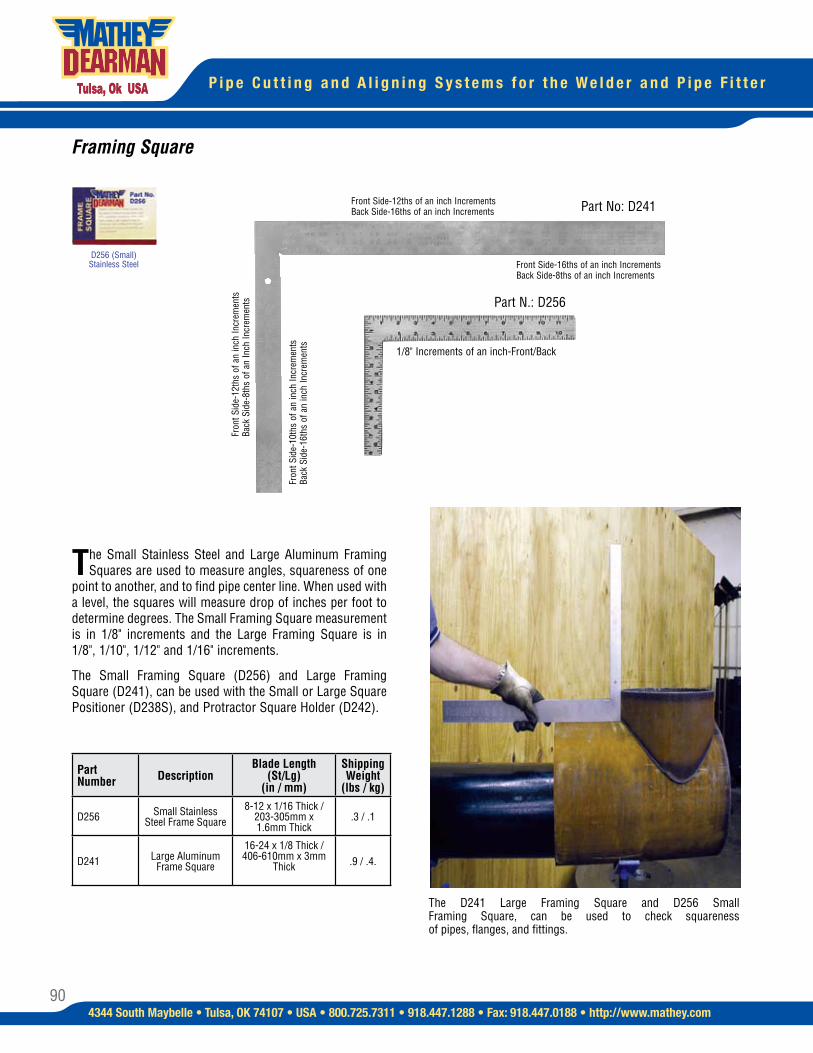
90
P i p e C u t t i n g a n d A l i g n i n g S y s t e m s f o r t h e W e l d e r a n d P i p e F i t t e r
4344 South Maybelle • Tulsa, OK 74107 • USA • 800.725.7311 • 918.447.1288 • Fax: 918.447.0188 • http://www.mathey.com
The Small Stainless Steel and Large Aluminum Framing Squares are used to measure angles, squareness of one
point to another, and to find pipe center line. When used with a level, the squares will measure drop of inches per foot to determine degrees. The Small Framing Square measurement is in 1/8" increments and the Large Framing Square is in 1/8", 1/10", 1/12" and 1/16" increments.
The Small Framing Square (D256) and Large Framing Square (D241), can be used with the Small or Large Square Positioner (D238S), and Protractor Square Holder (D242).
Framing Square
Part No: D241
Part N.: D256
1/8" Increments of an inch-Front/Back
D256 (Small) Stainless Steel
Part Number Description
Blade Length (St/Lg)
(in / mm)
Shipping Weight
(lbs / kg)
D256 Small Stainless Steel Frame Square
8-12 x 1/16 Thick / 203-305mm x 1.6mm Thick
.3 / .1
D241 Large Aluminum Frame Square
16-24 x 1/8 Thick / 406-610mm x 3mm
Thick .9 / .4.
The D241 Large Framing Square and D256 Small Framing Square, can be used to check squareness of pipes, flanges, and fittings.
Front Side-12ths of an inch Increments Back Side-16ths of an inch Increments
Fron
t Sid
e-12
ths
of a
n in
ch In
crem
ents
Ba
ck S
ide-
8ths
of a
n In
ch In
crem
ents
Front Side-16ths of an inch Increments Back Side-8ths of an inch Increments
Fron
t Sid
e-10
ths
of a
n in
ch In
crem
ents
Ba
ck S
ide-
16th
s of
an
inch
Incr
emen
ts
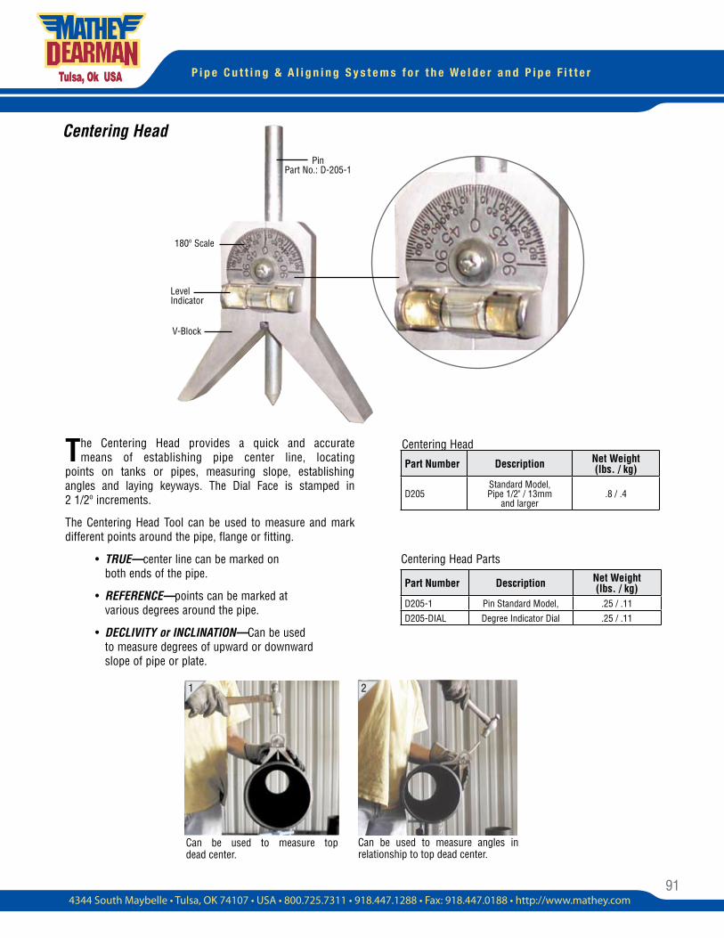
91
P i p e C u t t i n g & A l i g n i n g S y s t e m s f o r t h e W e l d e r a n d P i p e F i t t e r
The Centering Head provides a quick and accurate means of establishing pipe center line, locating
points on tanks or pipes, measuring slope, establishing angles and laying keyways. The Dial Face is stamped in 2 1/2º increments.
The Centering Head Tool can be used to measure and mark different points around the pipe, flange or fitting.
• TRUE—center line can be marked on both ends of the pipe.
• REFERENCE—points can be marked at various degrees around the pipe.
• DECLIVITY or INCLINATION—Can be used to measure degrees of upward or downward slope of pipe or plate.
Centering Head
Centering Head Parts
1 2
Pin Part No.: D-205-1
Level Indicator
V-Block
180º Scale
Part Number Description Net Weight(lbs. / kg)
D205Standard Model, Pipe 1/2" / 13mm
and larger.8 / .4
Part Number Description Net Weight(lbs. / kg)
D205-1 Pin Standard Model, .25 / .11
D205-DIAL Degree Indicator Dial .25 / .11
Can be used to measure top dead center.
Can be used to measure angles in relationship to top dead center.
Centering Head
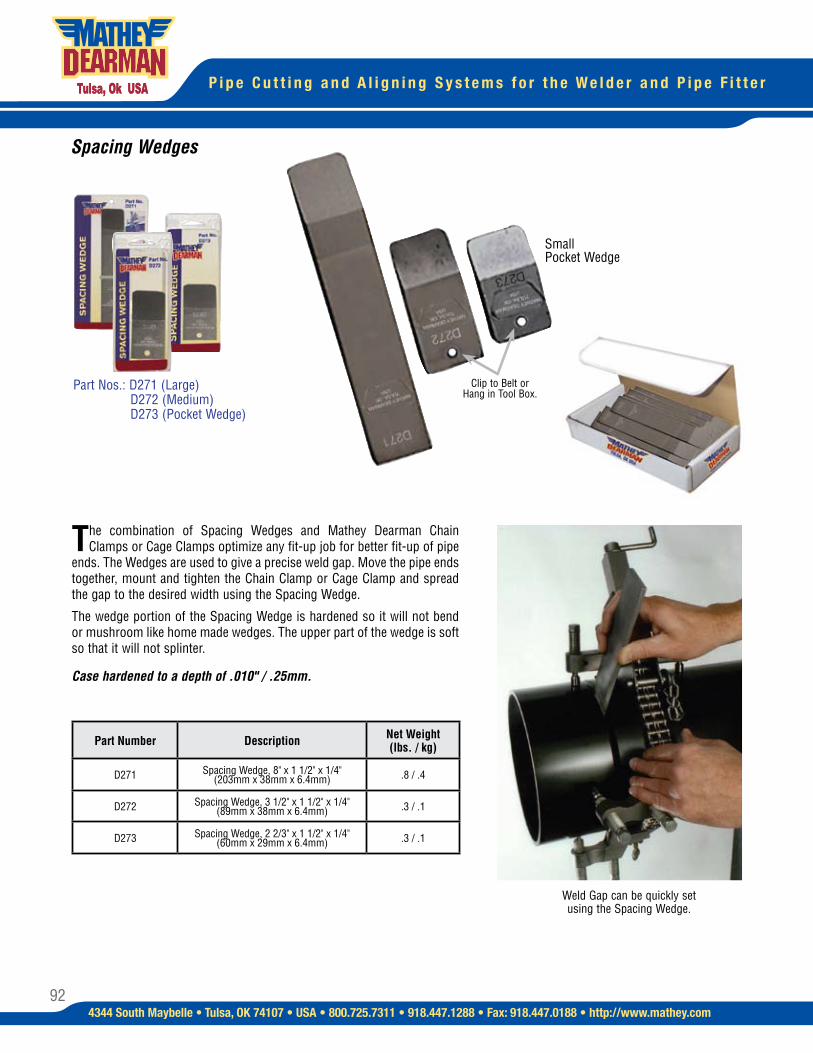
92
P i p e C u t t i n g a n d A l i g n i n g S y s t e m s f o r t h e W e l d e r a n d P i p e F i t t e r
4344 South Maybelle • Tulsa, OK 74107 • USA • 800.725.7311 • 918.447.1288 • Fax: 918.447.0188 • http://www.mathey.com
The combination of Spacing Wedges and Mathey Dearman Chain Clamps or Cage Clamps optimize any fit-up job for better fit-up of pipe
ends. The Wedges are used to give a precise weld gap. Move the pipe ends together, mount and tighten the Chain Clamp or Cage Clamp and spread the gap to the desired width using the Spacing Wedge.
The wedge portion of the Spacing Wedge is hardened so it will not bend or mushroom like home made wedges. The upper part of the wedge is soft so that it will not splinter.
Case hardened to a depth of .010" / .25mm.
Weld Gap can be quickly set using the Spacing Wedge.
Spacing Wedges
Clip to Belt or Hang in Tool Box.
Small Pocket Wedge
Part Nos.: D271 (Large) D272 (Medium) D273 (Pocket Wedge)
Part Number Description Net Weight(lbs. / kg)
D271 Spacing Wedge, 8" x 1 1/2" x 1/4" (203mm x 38mm x 6.4mm) .8 / .4
D272 Spacing Wedge, 3 1/2" x 1 1/2" x 1/4" (89mm x 38mm x 6.4mm) .3 / .1
D273 Spacing Wedge, 2 2/3" x 1 1/2" x 1/4" (60mm x 29mm x 6.4mm) .3 / .1
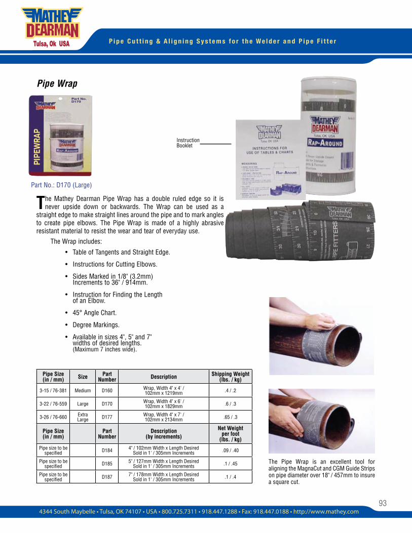
93
P i p e C u t t i n g & A l i g n i n g S y s t e m s f o r t h e W e l d e r a n d P i p e F i t t e r
Pipe Wrap
The Mathey Dearman Pipe Wrap has a double ruled edge so it is never upside down or backwards. The Wrap can be used as a
straight edge to make straight lines around the pipe and to mark angles to create pipe elbows. The Pipe Wrap is made of a highly abrasive resistant material to resist the wear and tear of everyday use.
Instruction Booklet
Part No.: D170 (Large)
The Wrap includes:
• Table of Tangents and Straight Edge.
• Instructions for Cutting Elbows.
• Sides Marked in 1/8" (3.2mm) Increments to 36" / 914mm.
• Instruction for Finding the Length of an Elbow.
• 45° Angle Chart.
• Degree Markings.
• Available in sizes 4", 5" and 7" widths of desired lengths. (Maximum 7 inches wide).
The Pipe Wrap is an excellent tool for aligning the MagnaCut and CGM Guide Strips on pipe diameter over 18" / 457mm to insure a square cut.
Pipe Size(in / mm) Size Part
Number Description Shipping Weight(lbs. / kg)
3-15 / 76-381 Medium D160 Wrap, Width 4" x 4' / 102mm x 1219mm .4 / .2
3-22 / 76-559 Large D170 Wrap, Width 4" x 6' / 102mm x 1829mm .6 / .3
3-26 / 76-660 Extra Large D177 Wrap, Width 4" x 7' /
102mm x 2134mm .65 / .3
Pipe Size (in / mm)
Part Number
Description(by increments)
Net Weight per foot
(lbs. / kg)Pipe size to be
specified D184 4" / 102mm Width x Length Desired Sold in 1' / 305mm Increments .09 / .40
Pipe size to be specified D185 5" / 127mm Width x Length Desired
Sold in 1' / 305mm Increments .1 / .45
Pipe size to be specified D187 7" / 178mm Width x Length Desired
Sold in 1' / 305mm Increments .1 / .4
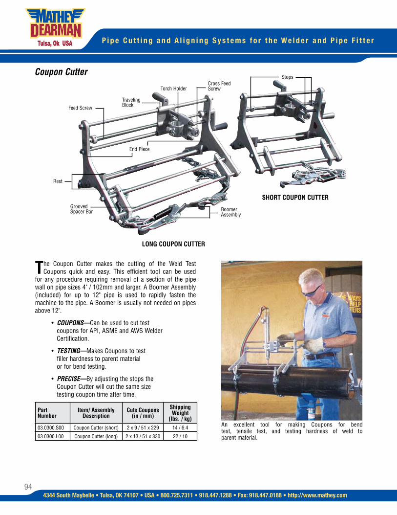
94
P i p e C u t t i n g a n d A l i g n i n g S y s t e m s f o r t h e W e l d e r a n d P i p e F i t t e r
4344 South Maybelle • Tulsa, OK 74107 • USA • 800.725.7311 • 918.447.1288 • Fax: 918.447.0188 • http://www.mathey.com
Coupon Cutter
The Coupon Cutter makes the cutting of the Weld Test Coupons quick and easy. This efficient tool can be used
for any procedure requiring removal of a section of the pipe wall on pipe sizes 4" / 102mm and larger. A Boomer Assembly (included) for up to 12" pipe is used to rapidly fasten the machine to the pipe. A Boomer is usually not needed on pipes above 12".
• COUPONS—Can be used to cut test coupons for API, ASME and AWS Welder Certification.
• TESTING—Makes Coupons to test filler hardness to parent material or for bend testing.
• PRECISE—By adjusting the stops the Coupon Cutter will cut the same size testing coupon time after time.
An excellent tool for making Coupons for bend test, tensile test, and testing hardness of weld to parent material.
Feed Screw
End Piece
Boomer Assembly
Grooved Spacer Bar
LONG COUPON CUTTER
SHORT COUPON CUTTER
Torch Holder
Stops
Rest
Cross Feed Screw
Traveling Block
Part Number
Item/ AssemblyDescription
Cuts Coupons(in / mm)
Shipping Weight
(lbs. / kg)03.0300.S00 Coupon Cutter (short) 2 x 9 / 51 x 229 14 / 6.4
03.0300.L00 Coupon Cutter (long) 2 x 13 / 51 x 330 22 / 10
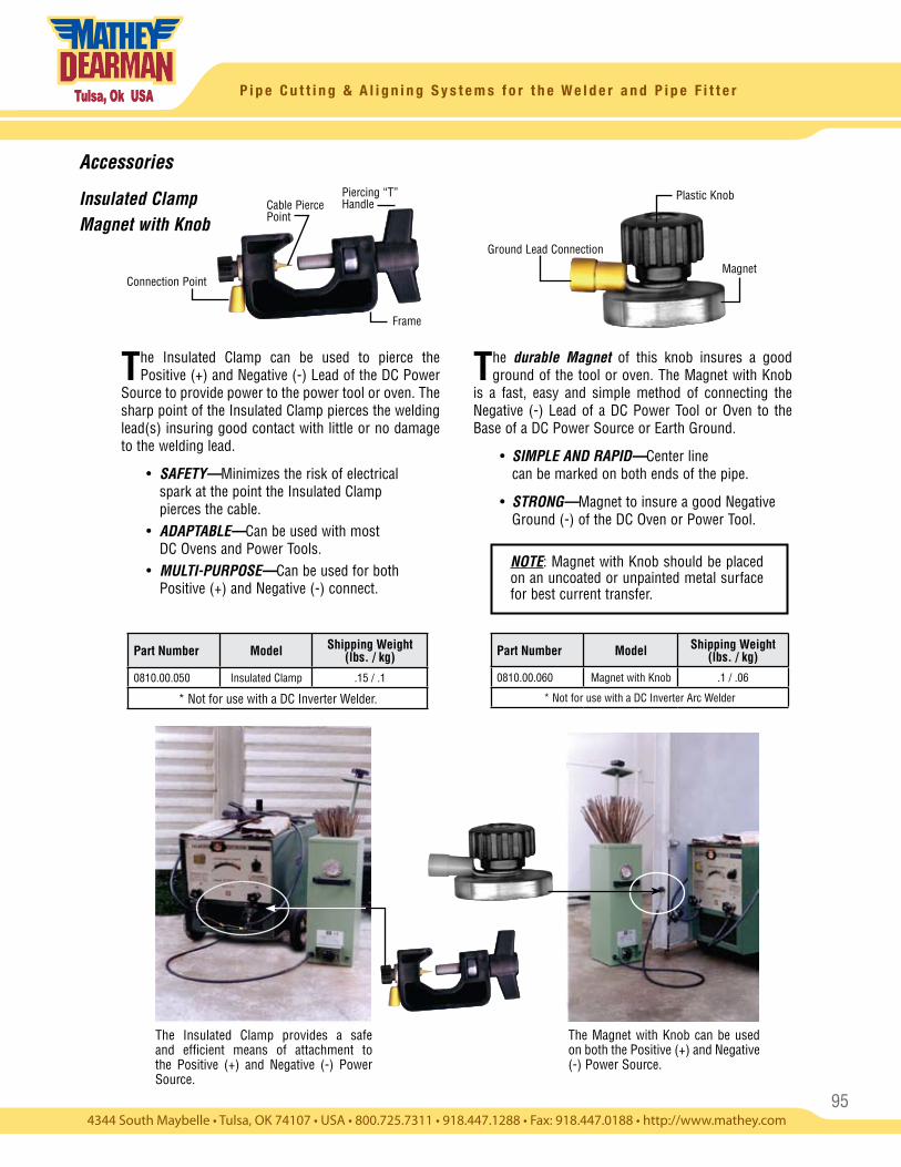
95
P i p e C u t t i n g & A l i g n i n g S y s t e m s f o r t h e W e l d e r a n d P i p e F i t t e r
Accessories
Insulated ClampMagnet with Knob
The Magnet with Knob can be used on both the Positive (+) and Negative (-) Power Source.
The durable Magnet of this knob insures a good ground of the tool or oven. The Magnet with Knob
is a fast, easy and simple method of connecting the Negative (-) Lead of a DC Power Tool or Oven to the Base of a DC Power Source or Earth Ground.
• SIMPLE AND RAPID—Center line can be marked on both ends of the pipe.
• STRONG—Magnet to insure a good Negative Ground (-) of the DC Oven or Power Tool.
NOTE: Magnet with Knob should be placed on an uncoated or unpainted metal surface for best current transfer.
The Insulated Clamp can be used to pierce the Positive (+) and Negative (-) Lead of the DC Power
Source to provide power to the power tool or oven. The sharp point of the Insulated Clamp pierces the welding lead(s) insuring good contact with little or no damage to the welding lead.
• SAFETY—Minimizes the risk of electrical spark at the point the Insulated Clamp pierces the cable. • ADAPTABLE—Can be used with most DC Ovens and Power Tools. • MULTI-PURPOSE—Can be used for both Positive (+) and Negative (-) connect.
The Insulated Clamp provides a safe and efficient means of attachment to the Positive (+) and Negative (-) Power Source.
Piercing “T” Handle
Frame
Cable Pierce Point
Connection Point
Plastic Knob
Magnet
Ground Lead Connection
Part Number Model Shipping Weight (lbs. / kg)
0810.00.060 Magnet with Knob .1 / .06
* Not for use with a DC Inverter Arc Welder
Part Number Model Shipping Weight (lbs. / kg)
0810.00.050 Insulated Clamp .15 / .1
* Not for use with a DC Inverter Welder.
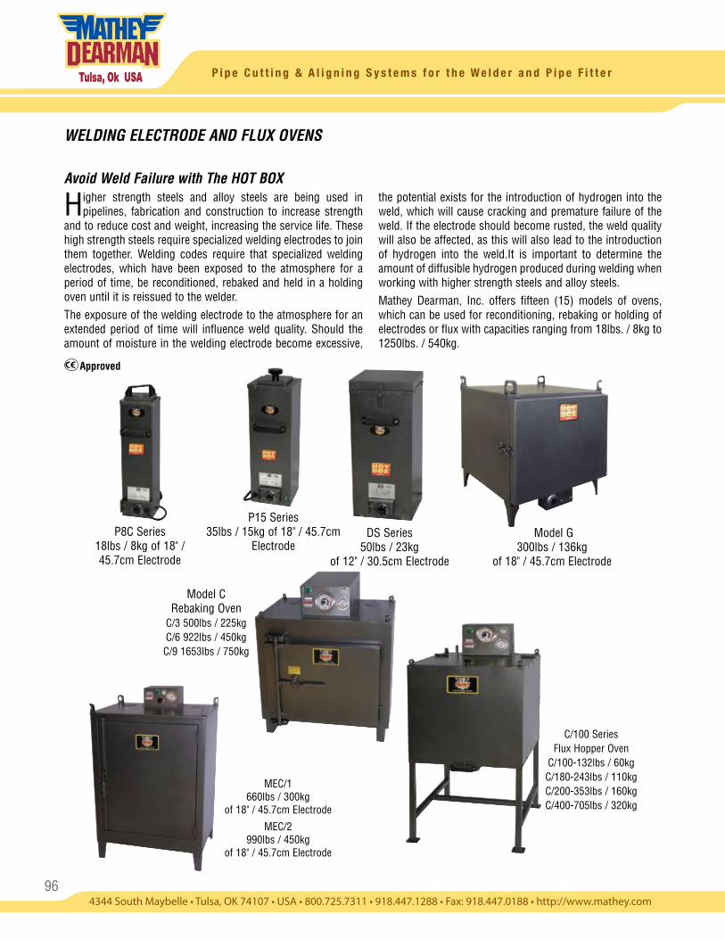
96
P i p e C u t t i n g & A l i g n i n g S y s t e m s f o r t h e W e l d e r a n d P i p e F i t t e r
WELDING ELECTRODE AND FLUX OVENS
Avoid Weld Failure with The HOT BOX
Higher strength steels and alloy steels are being used in pipelines, fabrication and construction to increase strength
and to reduce cost and weight, increasing the service life. These high strength steels require specialized welding electrodes to join them together. Welding codes require that specialized welding electrodes, which have been exposed to the atmosphere for a period of time, be reconditioned, rebaked and held in a holding oven until it is reissued to the welder.The exposure of the welding electrode to the atmosphere for an extended period of time will influence weld quality. Should the amount of moisture in the welding electrode become excessive,
the potential exists for the introduction of hydrogen into the weld, which will cause cracking and premature failure of the weld. If the electrode should become rusted, the weld quality will also be affected, as this will also lead to the introduction of hydrogen into the weld.It is important to determine the amount of diffusible hydrogen produced during welding when working with higher strength steels and alloy steels.Mathey Dearman, Inc. offers fifteen (15) models of ovens, which can be used for reconditioning, rebaking or holding of electrodes or flux with capacities ranging from 18lbs. / 8kg to 1250lbs. / 540kg.
P8C Series18lbs / 8kg of 18" / 45.7cm Electrode
P15 Series35lbs / 15kg of 18" / 45.7cm
Electrode Model G
300lbs / 136kg of 18" / 45.7cm Electrode
Model C Rebaking Oven
C/3 500lbs / 225kg C/6 922lbs / 450kg C/9 1653lbs / 750kg
C/100 Series Flux Hopper Oven
C/100-132lbs / 60kg C/180-243lbs / 110kg C/200-353lbs / 160kg C/400-705lbs / 320kg
MEC/1660lbs / 300kg
of 18" / 45.7cm Electrode
MEC/2990lbs / 450kg
of 18" / 45.7cm Electrode
Approved
DS Series50lbs / 23kg
of 12" / 30.5cm Electrode
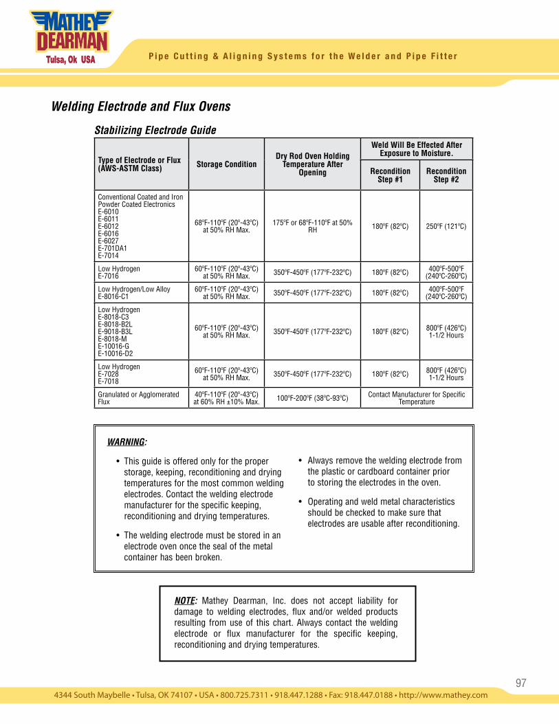
97
P i p e C u t t i n g & A l i g n i n g S y s t e m s f o r t h e W e l d e r a n d P i p e F i t t e r
Welding Electrode and Flux Ovens
WARNING:
• This guide is offered only for the proper storage, keeping, reconditioning and drying temperatures for the most common welding electrodes. Contact the welding electrode manufacturer for the specific keeping, reconditioning and drying temperatures.
• The welding electrode must be stored in an electrode oven once the seal of the metal container has been broken.
• Always remove the welding electrode from the plastic or cardboard container prior to storing the electrodes in the oven.
• Operating and weld metal characteristics should be checked to make sure that electrodes are usable after reconditioning.
Type of Electrode or Flux (AWS-ASTM Class) Storage Condition
Dry Rod Oven Holding Temperature After
Opening
Weld Will Be Effected After Exposure to Moisture.
Recondition Step #1
Recondition Step #2
Conventional Coated and Iron Powder Coated Electronics E-6010E-6011E-6012E-6016E-6027E-701DA1E-7014
68ºF-110ºF (20º-43ºC)at 50% RH Max.
175ºF or 68ºF-110ºF at 50% RH 180ºF (82ºC) 250ºF (121ºC)
Low HydrogenE-7016
60ºF-110ºF (20º-43ºC)at 50% RH Max. 350ºF-450ºF (177ºF-232ºC) 180ºF (82ºC) 400ºF-500ºF
(240ºC-260ºC)
Low Hydrogen/Low AlloyE-8016-C1
60ºF-110ºF (20º-43ºC)at 50% RH Max. 350ºF-450ºF (177ºF-232ºC) 180ºF (82ºC) 400ºF-500ºF
(240ºC-260ºC)
Low HydrogenE-8018-C3E-8018-B2LE-9018-B3LE-8018-ME-10016-GE-10016-D2
60ºF-110ºF (20º-43ºC)at 50% RH Max. 350ºF-450ºF (177ºF-232ºC) 180ºF (82ºC) 800ºF (426ºC)
1-1/2 Hours
Low HydrogenE-7028E-7018
60ºF-110ºF (20º-43ºC)at 50% RH Max. 350ºF-450ºF (177ºF-232ºC) 180ºF (82ºC) 800ºF (426ºC)
1-1/2 Hours
Granulated or AgglomeratedFlux
40ºF-110ºF (20º-43ºC)at 60% RH ±10% Max. 100ºF-200ºF (38ºC-93ºC) Contact Manufacturer for Specific
Temperature
NOTE: Mathey Dearman, Inc. does not accept liability for damage to welding electrodes, flux and/or welded products resulting from use of this chart. Always contact the welding electrode or flux manufacturer for the specific keeping, reconditioning and drying temperatures.
Stabilizing Electrode Guide
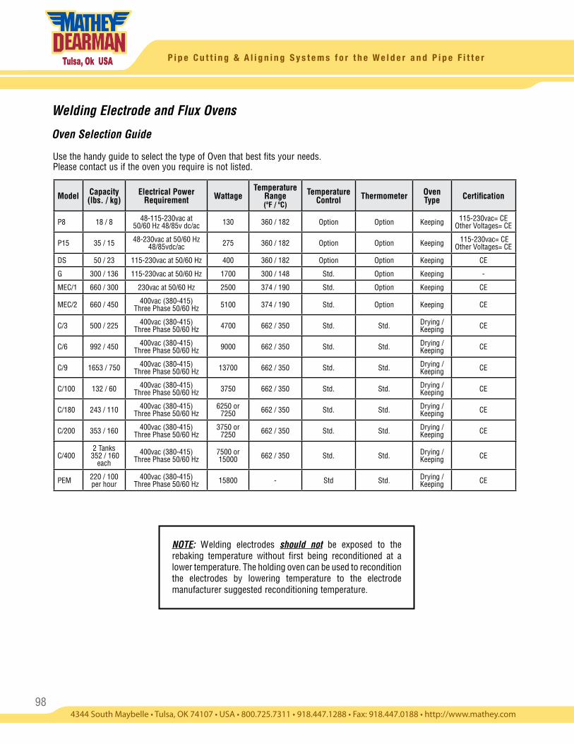
98
P i p e C u t t i n g & A l i g n i n g S y s t e m s f o r t h e W e l d e r a n d P i p e F i t t e r
Welding Electrode and Flux Ovens
Oven Selection Guide
Use the handy guide to select the type of Oven that best fits your needs. Please contact us if the oven you require is not listed.
Model Capacity (lbs. / kg)
Electrical Power Requirement Wattage
Temperature Range (ºF / ºC)
Temperature Control Thermometer Oven
Type Certification
P8 18 / 8 48-115-230vac at 50/60 Hz 48/85v dc/ac 130 360 / 182 Option Option Keeping 115-230vac= CE
Other Voltages= CE
P15 35 / 15 48-230vac at 50/60 Hz 48/85vdc/ac 275 360 / 182 Option Option Keeping 115-230vac= CE
Other Voltages= CE
DS 50 / 23 115-230vac at 50/60 Hz 400 360 / 182 Option Option Keeping CE
G 300 / 136 115-230vac at 50/60 Hz 1700 300 / 148 Std. Option Keeping -
MEC/1 660 / 300 230vac at 50/60 Hz 2500 374 / 190 Std. Option Keeping CE
MEC/2 660 / 450 400vac (380-415) Three Phase 50/60 Hz 5100 374 / 190 Std. Option Keeping CE
C/3 500 / 225 400vac (380-415) Three Phase 50/60 Hz 4700 662 / 350 Std. Std. Drying /
Keeping CE
C/6 992 / 450 400vac (380-415) Three Phase 50/60 Hz 9000 662 / 350 Std. Std. Drying /
Keeping CE
C/9 1653 / 750 400vac (380-415) Three Phase 50/60 Hz 13700 662 / 350 Std. Std. Drying /
Keeping CE
C/100 132 / 60 400vac (380-415) Three Phase 50/60 Hz 3750 662 / 350 Std. Std. Drying /
Keeping CE
C/180 243 / 110 400vac (380-415) Three Phase 50/60 Hz
6250 or 7250 662 / 350 Std. Std. Drying /
Keeping CE
C/200 353 / 160 400vac (380-415) Three Phase 50/60 Hz
3750 or 7250 662 / 350 Std. Std. Drying /
Keeping CE
C/4002 Tanks
352 / 160 each
400vac (380-415) Three Phase 50/60 Hz
7500 or 15000 662 / 350 Std. Std. Drying /
Keeping CE
PEM 220 / 100 per hour
400vac (380-415) Three Phase 50/60 Hz 15800 - Std Std. Drying /
Keeping CE
NOTE: Welding electrodes should not be exposed to the rebaking temperature without first being reconditioned at a lower temperature. The holding oven can be used to recondition the electrodes by lowering temperature to the electrode manufacturer suggested reconditioning temperature.
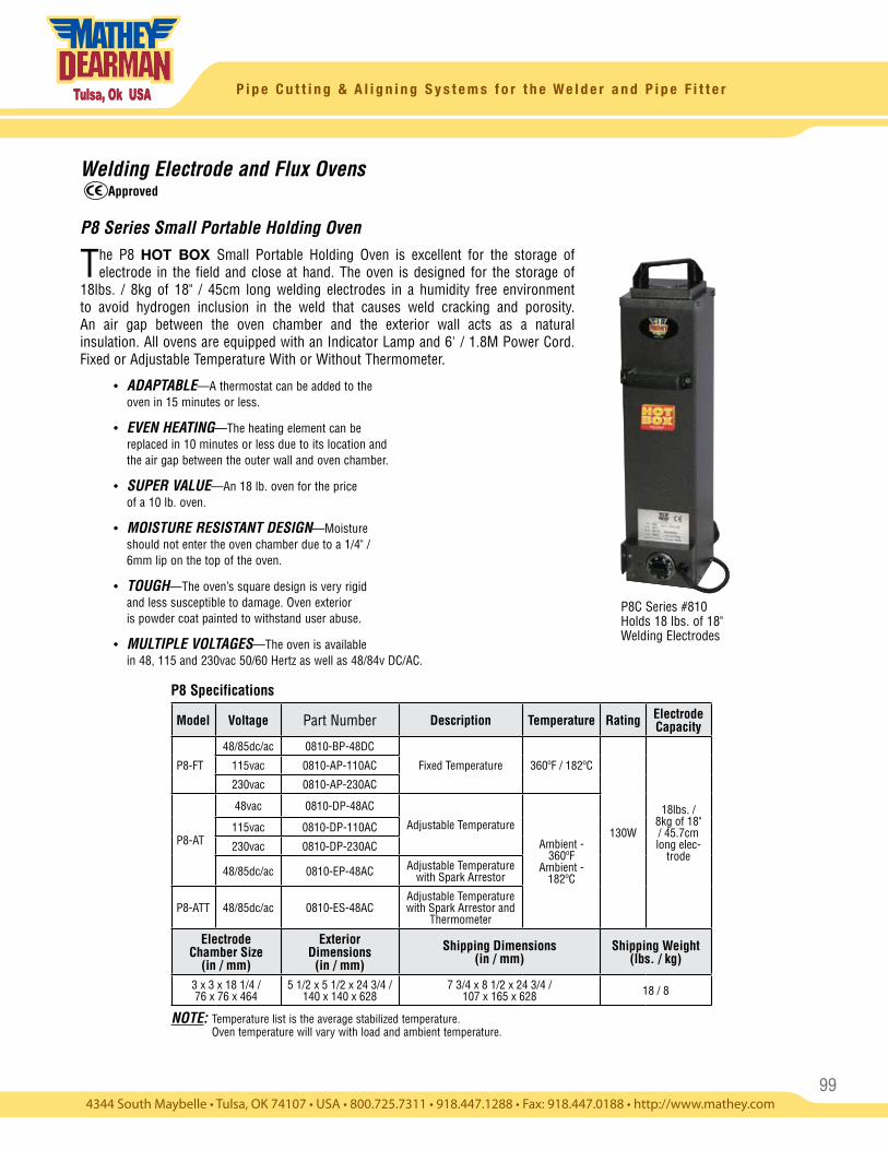
99
P i p e C u t t i n g & A l i g n i n g S y s t e m s f o r t h e W e l d e r a n d P i p e F i t t e r
Welding Electrode and Flux Ovens
P8 Series Small Portable Holding Oven
The P8 HOT BOX Small Portable Holding Oven is excellent for the storage of electrode in the field and close at hand. The oven is designed for the storage of
18lbs. / 8kg of 18" / 45cm long welding electrodes in a humidity free environment to avoid hydrogen inclusion in the weld that causes weld cracking and porosity. An air gap between the oven chamber and the exterior wall acts as a natural insulation. All ovens are equipped with an Indicator Lamp and 6' / 1.8M Power Cord. Fixed or Adjustable Temperature With or Without Thermometer.
• ADAPTABLE—A thermostat can be added to the oven in 15 minutes or less.
• EVEN HEATING—The heating element can be replaced in 10 minutes or less due to its location and the air gap between the outer wall and oven chamber.
• SUPER VALUE—An 18 lb. oven for the price of a 10 lb. oven.
• MOISTURE RESISTANT DESIGN—Moisture should not enter the oven chamber due to a 1/4" / 6mm lip on the top of the oven.
• TOUGH—The oven’s square design is very rigid and less susceptible to damage. Oven exterior is powder coat painted to withstand user abuse.
• MULTIPLE VOLTAGES—The oven is available in 48, 115 and 230vac 50/60 Hertz as well as 48/84v DC/AC.
P8C Series #810Holds 18 lbs. of 18"Welding Electrodes
NOTE: Temperature list is the average stabilized temperature. Oven temperature will vary with load and ambient temperature.
P8 Specifications
Model Voltage Part Number Description Temperature Rating Electrode Capacity
P8-FT
48/85dc/ac 0810-BP-48DC
Fixed Temperature 360ºF / 182ºC
130W
18lbs. / 8kg of 18" / 45.7cm long elec-
trode
115vac 0810-AP-110AC
230vac 0810-AP-230AC
P8-AT
48vac 0810-DP-48AC
Adjustable Temperature
Ambient - 360ºF
Ambient - 182ºC
115vac 0810-DP-110AC
230vac 0810-DP-230AC
48/85dc/ac 0810-EP-48AC Adjustable Temperature with Spark Arrestor
P8-ATT 48/85dc/ac 0810-ES-48ACAdjustable Temperature with Spark Arrestor and
Thermometer
Electrode Chamber Size
(in / mm)
Exterior Dimensions
(in / mm)Shipping Dimensions
(in / mm)Shipping Weight
(lbs. / kg)
3 x 3 x 18 1/4 / 76 x 76 x 464
5 1/2 x 5 1/2 x 24 3/4 / 140 x 140 x 628
7 3/4 x 8 1/2 x 24 3/4 / 107 x 165 x 628 18 / 8
Approved
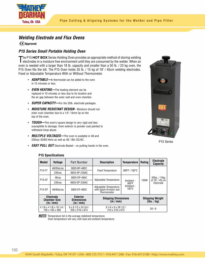
100
P i p e C u t t i n g & A l i g n i n g S y s t e m s f o r t h e W e l d e r a n d P i p e F i t t e r
P15 Series
P15 Specifications
Welding Electrode and Flux Ovens
P15 Series Small Portable Holding Oven
The P15 HOT BOX Series Holding Oven provides an appropriate method of storing welding electrodes in a moisture free environment until they are consumed by the welder. When an
oven is needed with a larger than 18 lb. capacity and smaller than a 50 lb. / 23 kg oven, the P15 Oven fits the bill. The P15 Oven holds 35 lb. / 15 kg of 18" / 45cm welding electrodes. Fixed or Adjustable Temperature With or Without Thermometer.
• ADAPTABLE—A thermostat can be added to the oven in 15 minutes or less.
• EVEN HEATING—The heating element can be replaced in 10 minutes or less due to its location and
the air gap between the outer wall and oven chamber.
• SUPER CAPACITY—For the 35lb. electrode packages.
• MOISTURE RESISTANT DESIGN - Moisture should not enter oven chamber due to a 1/4" / 6mm lip on the top of the oven.
• TOUGH—The oven’s square design is very rigid and less susceptible to damage. Oven exterior is powder coat painted to withstand shop abuse.
• MULTIPLE VOLTAGES—The oven is available in 48 and 230vac 50/60 Hertz as well as 48 / 85v DC/AC.
• EASY PULL OUT Electrode Basket - no putting hands in the oven.
Approved
Model Voltage Part Number Description Temperature Rating Electrode Capacity
P15-FT48/85dc/ac 0820-BP-48DC
Fixed Temperature 360ºF / 182ºC
130W35lbs. / 15kg of 18" / 45.cm
Electrode
230vac 0820-AP-230AC
P15-AT48vac 0820-DP-48AC
Adjustable Temperature Ambient - 360ºF
Ambient - 182ºC
230vac 0820-DP-230AC
P15-EP 48/85dc/ac 0820-EP-48DCAdjustable Temperature with Spark Arrestor and
Thermometer
Electrode Chamber Size
(in / mm)
Exterior Dimensions
(in / mm)Shipping Dimensions
(in / mm)Shipping Weight
(lbs. / kg)
4 1/8 x 4 1/8 x 18 1/4 / 105 x 105 x 469
8 x 8 1/2 x 24 3/4 / 203 x 216 x 673
8 1/4 x 9 x 26 1/2 / 210 x 216 x 673 20 / 9
NOTE: Temperature list is the average stabilized temperature. Oven temperature will vary with load and ambient temperature.
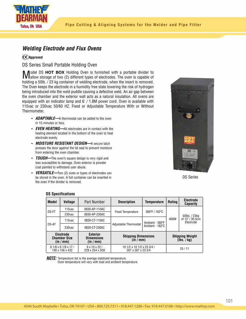
101
P i p e C u t t i n g & A l i g n i n g S y s t e m s f o r t h e W e l d e r a n d P i p e F i t t e r
DS Series
DS Specifications
Welding Electrode and Flux Ovens
DS Series Small Portable Holding Oven
Model DS HOT BOX Holding Oven is furnished with a portable divider to allow storage of two (2) different types of electrodes. The oven is capable of
holding a 50lb. / 23 kg container of welding electrode, when the insert is removed. The Oven keeps the electrode in a humidity free state lowering the risk of hydrogen being introduced into the weld puddle causing a defective weld. An air gap between the oven chamber and the exterior wall acts as a natural insulation. All ovens are equipped with an indicator lamp and 6' / 1.8M power cord. Oven is available with 115vac or 230vac 50/60 HZ. Fixed or Adjustable Temperature With or Without Thermometer.
• ADAPTABLE—A thermostat can be added to the oven in 15 minutes or less.
• EVEN HEATING—All electrodes are in contact with the heating element located in the bottom of the oven to heat electrode evenly.
• MOISTURE RESISTANT DESIGN—A secure latch presses the door against the lid seal to prevent moisture from entering the oven chamber.
• TOUGH—The oven’s square design is very rigid and less susceptible to damage. Oven exterior is powder coat painted to withstand user abuse.
• VERSATILE—Two (2) sizes or types of electrodes can be stored in the oven. A full container can be inserted in the oven if the divider is removed.
Approved
Model Voltage Part Number Description Temperature Rating Electrode Capacity
DS-FT115vac 0830-AP-110AC
Fixed Temperature 360ºF / 182ºC
400W50lbs. / 23kg
of 12" / 30.5cm Electrode
230vac 0830-AP-230AC
DS-AT115vac 0830-CT-110AC
Adjustable Thermostat Ambient - 360ºF Ambient - 182ºC230vac 0830-CT-230AC
Electrode Chamber Size
(in / mm)
Exterior Dimensions
(in / mm)Shipping Dimensions
(in / mm)Shipping Weight
(lbs. / kg)
6 1/8 x 6 1/8 x 17 / 156 x 156 x 432
9 x 10 x 22 / 229 x 254 x 559
10 1/2 x 10 1/2 x 23 3/4 / 267 x 267 x 23 3/4 25 / 11
NOTE: Temperature list is the average stabilized temperature. Oven temperature will vary with load and ambient temperature.
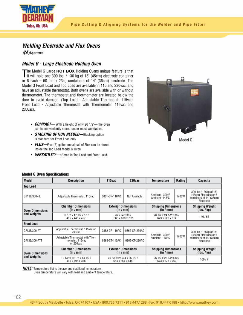
102
P i p e C u t t i n g & A l i g n i n g S y s t e m s f o r t h e W e l d e r a n d P i p e F i t t e r
Welding Electrode and Flux Ovens
Model G - Large Electrode Holding Oven
The Model G Large HOT BOX Holding Ovens unique feature is that it will hold one 300 lbs. / 136 kg of 18" (45cm) electrode container
or 6 each – 50 lbs. / 23kg containers of 14" (36cm) electrode. The Model G Front Load and Top Load are available in 115 and 230vac, and have an adjustable thermostat. Both ovens are available with or without thermometer. The thermostat and thermometer are located below the door to avoid damage. (Top Load - Adjustable Thermostat, 115vac. Front Load - Adjustable Thermostat with Thermometer, 115vac and 230vac).
• COMPACT— With a height of only 26 1/2"— the oven can be conveniently stored under most worktables.
• STACKING OPTION NEEDED—Stacking option is standard for Front Load only.
• FLUX—Five (5) gallon metal pail of Flux can be stored inside the Top Load Model G Oven.
• VERSATILITY—offered in Top Load and Front Load.
Model G Oven SpecificationsModel Description 115vac 230vac Temperature Rating Capacity
Top Load
GT136/300-FL Adjustable Thermostat, 115vac 0861-CP-110AC Not Available Ambient - 300ºF Ambient -148ºC 1700W
300 lbs / 136kg of 18" (45cm) Electrode or 6
containers of 14" (36cm) Electrode
Oven Dimensions and Weights
Chamber Dimensions (in / mm)
Exterior Dimensions (in / mm)
Shipping Dimensions (in / mm)
Shipping Weight (lbs. / kg)
19 1/2 x 17 1/2 x 18 / 495 x 445 x 457
26 x 24 x 30 / 660 x 610 x 762
26 1/2 x 24 1/2 x 36 / 673 x 622 x 914 140 / 64
Front Load
GF136/300-AT Adjustable Thermostat, 115vac or 230vac 0862-CP-110AC 0862-CP-230AC
Ambient - 300ºFAmbient -148º C 1700W
300 lbs / 136kg of 18" (45cm) Electrode or 6
containers of 14" (36cm) ElectrodeGF136/300-ATT
Adjustable Thermostat with Ther-mometer, 115vac
or 230vac0862-CT-110AC 0862-CT-230AC
Oven Dimensions and Weights
Chamber Dimensions (in / mm)
Exterior Dimensions (in / mm)
Shipping Dimensions (in / mm)
Shipping Weight (lbs. / kg)
19 1/2 x 19 1/2 x 14 1/2 / 495 x 495 x 368
25 3/4 x 25 3/4 x 25 1/2 / 654 x 654 x 648
26 1/2 x 26 1/2 x 30 / 673 x 673 x 762 160 / 7
Model G
Approved
NOTE: Temperature list is the average stabilized temperature. Oven temperature will vary with load and ambient temperature.
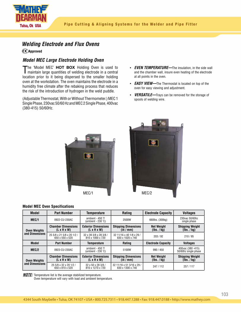
103
P i p e C u t t i n g & A l i g n i n g S y s t e m s f o r t h e W e l d e r a n d P i p e F i t t e r
Welding Electrode and Flux Ovens
Model MEC Large Electrode Holding Oven
The ‘Model MEC’ HOT BOX Holding Oven is used to maintain large quantities of welding electrode in a central
location prior to it being dispersed to the smaller holding oven at the workstation. The oven maintains the electrode in a humidity free climate after the rebaking process that reduces the risk of the introduction of hydrogen in the weld puddle.
(Adjustable Thermostat, With or Without Thermometer.) MEC 1 Single Phase, 230vac 50/60 Hz and MEC 2 Single Phase, 400vac (380-415) 50/60Hz.
Model MEC Oven Specifications
Approved
MEC/1 MEC/2
• EVEN TEMPERATURE—The insulation, in the side wall and the chamber wall, insure even heating of the electrode at all points in the oven.
• EASY VIEW—The Thermostat is located on top of the oven for easy viewing and adjustment.
• VERSATILE—Trays can be removed for the storage of spools of welding wire.
Model Part Number Temperature Rating Electrode Capacity Voltages
MEC/1 0922-CU-230AC ambient - 450 ˚F(ambient - 230 ˚C) 2500W 660lbs. (300kg) 230vac 50/60hz
single phase
Oven Weights and Dimensions
Chamber Dimensions (L x H x W)
Exterior Dimensions (L x H x W)
Shipping Dimensions (in / mm)
Net Weight (lbs. / kg)
Shipping Weight (lbs. / kg)
25 5/8 x 21 5/8 x 20 1/2 / 650 x 550 x 520
32 x 39 3/8 x 28 3/8 / 810 x 1000 x 720
32 11/16 x 40 1/8 x 29 / 830 x 1020 x 740 203 / 92 210 / 95
Model Part Number Temperature Rating Electrode Capacity Voltages
MEC/2 0923-CU-230AC ambient - 450 ˚F(ambient - 230 ˚C) 5100W 990 / 450 400vac (380 -415)
50/60hz single phase
Oven Weights and Dimensions
Chamber Dimensions (L x H x W)
Exterior Dimensions (L x H x W)
Shipping Dimensions (in / mm)
Net Weight (lbs. / kg)
Shipping Weight (lbs. / kg)
25 5/8 x 32 x 20 1/2 / 650 x 810 x 520
32 x 50 x 28 3/8 / 810 x 1270 x 720
32 11/16 x 51 3/16 x 29 / 830 x 1300 x 740 247 / 112 257 / 117
NOTE: Temperature list is the average stabilized temperature. Oven temperature will vary with load and ambient temperature.
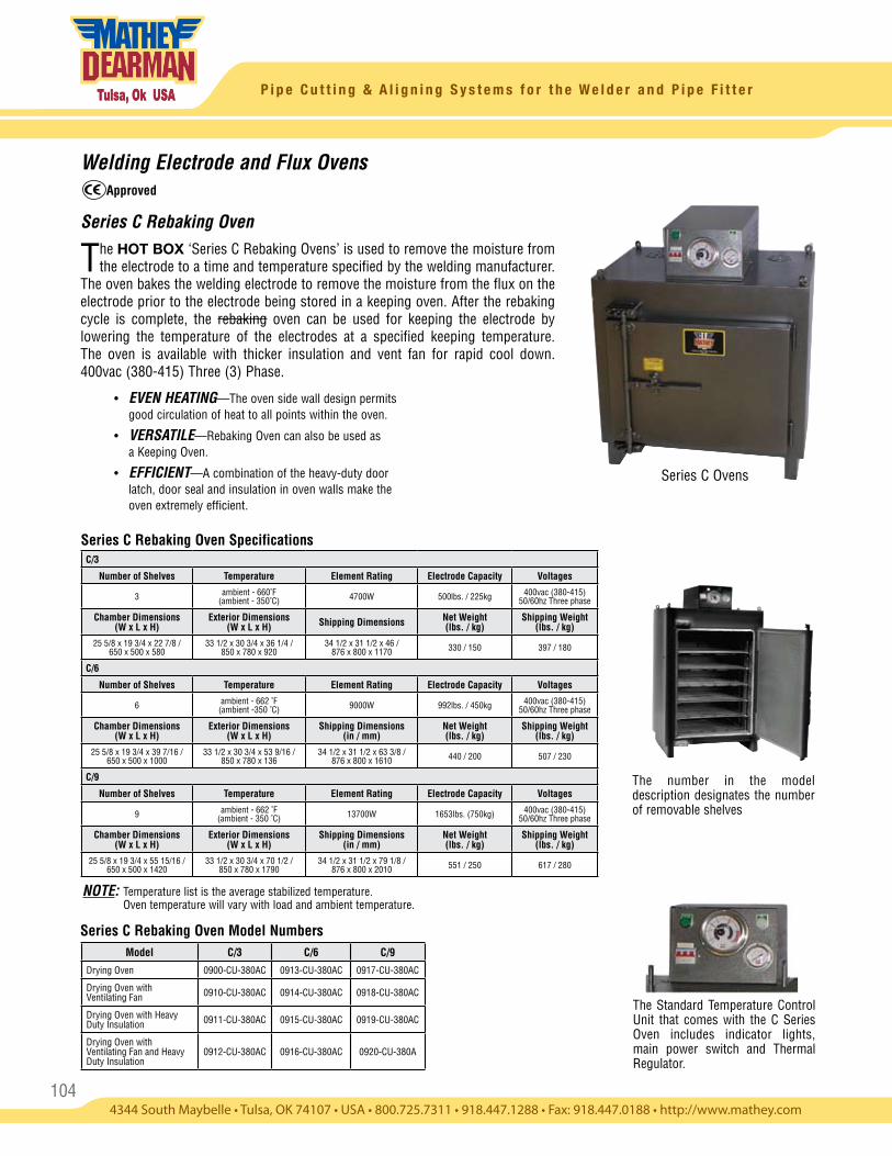
104
P i p e C u t t i n g & A l i g n i n g S y s t e m s f o r t h e W e l d e r a n d P i p e F i t t e r
Welding Electrode and Flux Ovens
Series C Rebaking Oven
The HOT BOX ‘Series C Rebaking Ovens’ is used to remove the moisture from the electrode to a time and temperature specified by the welding manufacturer.
The oven bakes the welding electrode to remove the moisture from the flux on the electrode prior to the electrode being stored in a keeping oven. After the rebaking cycle is complete, the rebaking oven can be used for keeping the electrode by lowering the temperature of the electrodes at a specified keeping temperature. The oven is available with thicker insulation and vent fan for rapid cool down. 400vac (380-415) Three (3) Phase.
• EVEN HEATING—The oven side wall design permits good circulation of heat to all points within the oven.
• VERSATILE—Rebaking Oven can also be used as a Keeping Oven.
• EFFICIENT—A combination of the heavy-duty door latch, door seal and insulation in oven walls make the oven extremely efficient.
Series C Ovens
The number in the model description designates the number of removable shelves
The Standard Temperature Control Unit that comes with the C Series Oven includes indicator lights, main power switch and Thermal Regulator.
Series C Rebaking Oven Specifications
Series C Rebaking Oven Model Numbers
Approved
C/3
Number of Shelves Temperature Element Rating Electrode Capacity Voltages
3 ambient - 660˚F (ambient - 350˚C) 4700W 500lbs. / 225kg 400vac (380-415)
50/60hz Three phase
Chamber Dimensions (W x L x H)
Exterior Dimensions (W x L x H) Shipping Dimensions Net Weight
(lbs. / kg)Shipping Weight
(lbs. / kg)
25 5/8 x 19 3/4 x 22 7/8 / 650 x 500 x 580
33 1/2 x 30 3/4 x 36 1/4 / 850 x 780 x 920
34 1/2 x 31 1/2 x 46 / 876 x 800 x 1170 330 / 150 397 / 180
C/6
Number of Shelves Temperature Element Rating Electrode Capacity Voltages
6 ambient - 662 ˚F (ambient -350 ˚C) 9000W 992lbs. / 450kg 400vac (380-415)
50/60hz Three phase
Chamber Dimensions (W x L x H)
Exterior Dimensions (W x L x H)
Shipping Dimensions (in / mm)
Net Weight (lbs. / kg)
Shipping Weight (lbs. / kg)
25 5/8 x 19 3/4 x 39 7/16 / 650 x 500 x 1000
33 1/2 x 30 3/4 x 53 9/16 / 850 x 780 x 136
34 1/2 x 31 1/2 x 63 3/8 / 876 x 800 x 1610 440 / 200 507 / 230
C/9
Number of Shelves Temperature Element Rating Electrode Capacity Voltages
9 ambient - 662 ˚F (ambient - 350 ˚C) 13700W 1653lbs. (750kg) 400vac (380-415)
50/60hz Three phase
Chamber Dimensions (W x L x H)
Exterior Dimensions (W x L x H)
Shipping Dimensions (in / mm)
Net Weight (lbs. / kg)
Shipping Weight (lbs. / kg)
25 5/8 x 19 3/4 x 55 15/16 / 650 x 500 x 1420
33 1/2 x 30 3/4 x 70 1/2 / 850 x 780 x 1790
34 1/2 x 31 1/2 x 79 1/8 / 876 x 800 x 2010 551 / 250 617 / 280
Model C/3 C/6 C/9
Drying Oven 0900-CU-380AC 0913-CU-380AC 0917-CU-380AC
Drying Oven withVentilating Fan 0910-CU-380AC 0914-CU-380AC 0918-CU-380AC
Drying Oven with Heavy Duty Insulation 0911-CU-380AC 0915-CU-380AC 0919-CU-380AC
Drying Oven withVentilating Fan and Heavy Duty Insulation
0912-CU-380AC 0916-CU-380AC 0920-CU-380A
NOTE: Temperature list is the average stabilized temperature. Oven temperature will vary with load and ambient temperature.
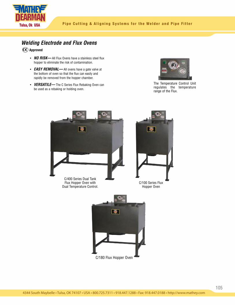
105
P i p e C u t t i n g & A l i g n i n g S y s t e m s f o r t h e W e l d e r a n d P i p e F i t t e r
Welding Electrode and Flux Ovens
• NO RISK— All Flux Ovens have a stainless steel flux hopper to eliminate the risk of contamination.
• EASY REMOVAL— All ovens have a gate valve at the bottom of oven so that the flux can easily and rapidly be removed from the hopper chamber.
• VERSATILE— The C Series Flux Rebaking Oven can be used as a rebaking or holding oven.
C/100 Series Flux Hopper Oven
C/400 Series Dual Tank Flux Hopper Oven with
Dual Temperature Control.
C/180 Flux Hopper Oven
The Temperature Control Unit regulates the temperature range of the Flux.
Approved
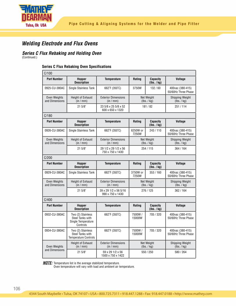
106
P i p e C u t t i n g & A l i g n i n g S y s t e m s f o r t h e W e l d e r a n d P i p e F i t t e r
Welding Electrode and Flux Ovens
Series C Flux Rebaking and Holding Oven (Continued.)
Series C Flux Rebaking Oven Specifications
C/100
Part Number Hopper Description
Temperature Rating Capacity (lbs. / kg)
Voltage
0925-CU-380AC Single Stainless Tank 662˚F (350˚C) 3750W 132 / 60 400vac (380-415) 50/60Hz Three Phase
Oven Weights and Dimensions
Height of Exhaust (in / mm)
Exterior Dimensions (in / mm)
Net Weight (lbs. / kg)
Shipping Weight (lbs. / kg)
21 5/8" 23 5/8 x 25 5/8 x 52 600 x 650 x 1320
181 / 82 251 / 114
C/180
Part Number Hopper Description
Temperature Rating Capacity (lbs. / kg)
Voltage
0926-CU-380AC Single Stainless Tank 662˚F (350˚C) 6250W or 7250W
243 / 110 400vac (380-415) 50/60Hz Three Phase
Oven Weights and Dimensions
Height of Exhaust (in / mm)
Exterior Dimensions (in / mm)
Net Weight (lbs. / kg)
Shipping Weight (lbs. / kg)
21 5/8" 29 1/2 x 29 1/2 x 56 750 x 750 x 1430
254 / 115 364 / 164
C/200
Part Number Hopper Description
Temperature Rating Capacity (lbs. / kg)
Voltage
0929-CU-380AC Single Stainless Tank 662˚F (350˚C) 3750W or 7250W
353 / 160 400vac (380-415) 50/60Hz Three Phase
Oven Weights and Dimensions
Height of Exhaust (in / mm)
Exterior Dimensions (in / mm)
Net Weight (lbs. / kg)
Shipping Weight (lbs. / kg)
21 5/8" 39 x 29 1/2 x 56 5/16 990 x 750 x 1430
276 / 125 362 / 164
C/400
Part Number Hopper Description
Temperature Rating Capacity (lbs. / kg)
Voltage
0932-CU-380AC Two (2) Stainless Steel Tanks with
Single Temperature Controls
662˚F (350˚C) 7500W / 15000W
705 / 320 400vac (380-415) 50/60Hz Three Phase
0934-CU-380AC Two (2) Stainless Steel Tanks with
Temperature Controls
662˚F (350˚C) 7500W / 15000W
705 / 320 400vac (380-415) 50/60Hz Three Phase
Oven Weights and Dimensions
Height of Exhaust (in / mm)
Exterior Dimensions (in / mm)
Net Weight (lbs. / kg)
Shipping Weight (lbs. / kg)
21 5/8" 59 x 29 1/2 x 56 1500 x 750 x 1422
550 / 250 580 / 264
NOTE: Temperature list is the average stabilized temperature. Oven temperature will vary with load and ambient air temperature.
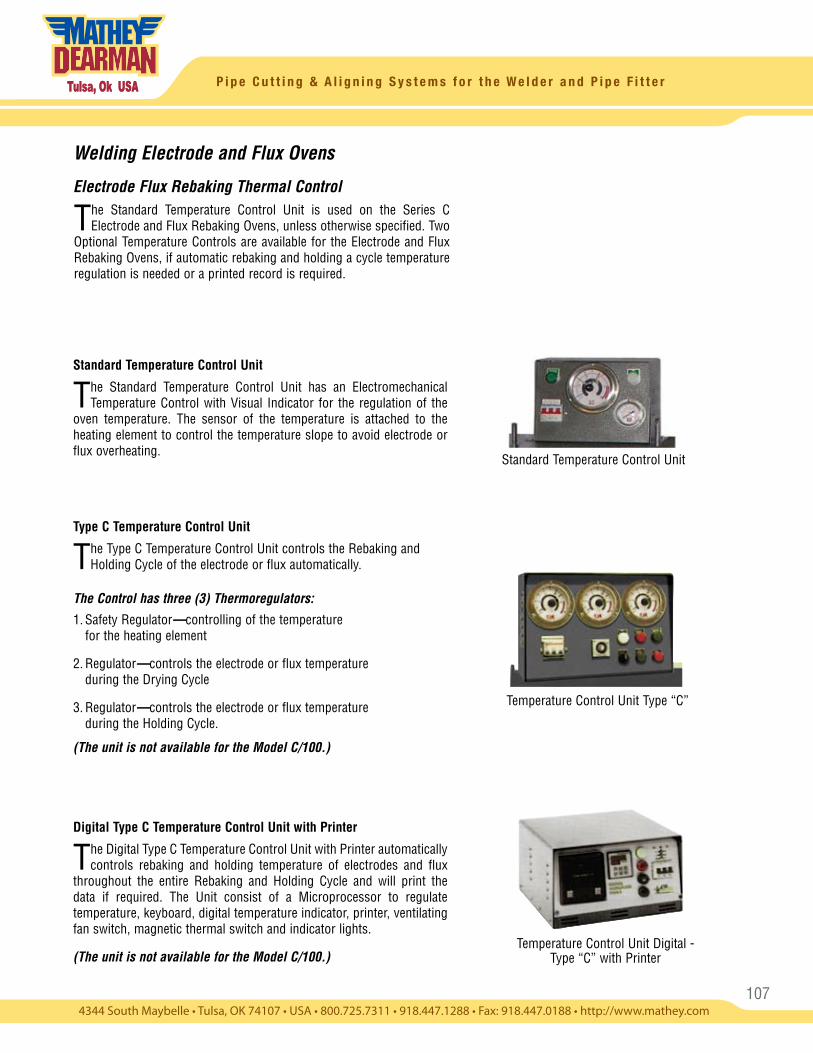
107
P i p e C u t t i n g & A l i g n i n g S y s t e m s f o r t h e W e l d e r a n d P i p e F i t t e r
Standard Temperature Control Unit
Temperature Control Unit Type “C”
Temperature Control Unit Digital - Type “C” with Printer
Welding Electrode and Flux Ovens
Electrode Flux Rebaking Thermal Control
Standard Temperature Control Unit
The Standard Temperature Control Unit has an Electromechanical Temperature Control with Visual Indicator for the regulation of the
oven temperature. The sensor of the temperature is attached to the heating element to control the temperature slope to avoid electrode or flux overheating.
Type C Temperature Control Unit
The Type C Temperature Control Unit controls the Rebaking and Holding Cycle of the electrode or flux automatically.
The Control has three (3) Thermoregulators:
1. Safety Regulator—controlling of the temperature for the heating element
2. Regulator—controls the electrode or flux temperature during the Drying Cycle
3. Regulator—controls the electrode or flux temperature during the Holding Cycle.
(The unit is not available for the Model C/100.)
Digital Type C Temperature Control Unit with Printer
The Digital Type C Temperature Control Unit with Printer automatically controls rebaking and holding temperature of electrodes and flux
throughout the entire Rebaking and Holding Cycle and will print the data if required. The Unit consist of a Microprocessor to regulate temperature, keyboard, digital temperature indicator, printer, ventilating fan switch, magnetic thermal switch and indicator lights.
(The unit is not available for the Model C/100.)
The Standard Temperature Control Unit is used on the Series C Electrode and Flux Rebaking Ovens, unless otherwise specified. Two
Optional Temperature Controls are available for the Electrode and Flux Rebaking Ovens, if automatic rebaking and holding a cycle temperature regulation is needed or a printed record is required.
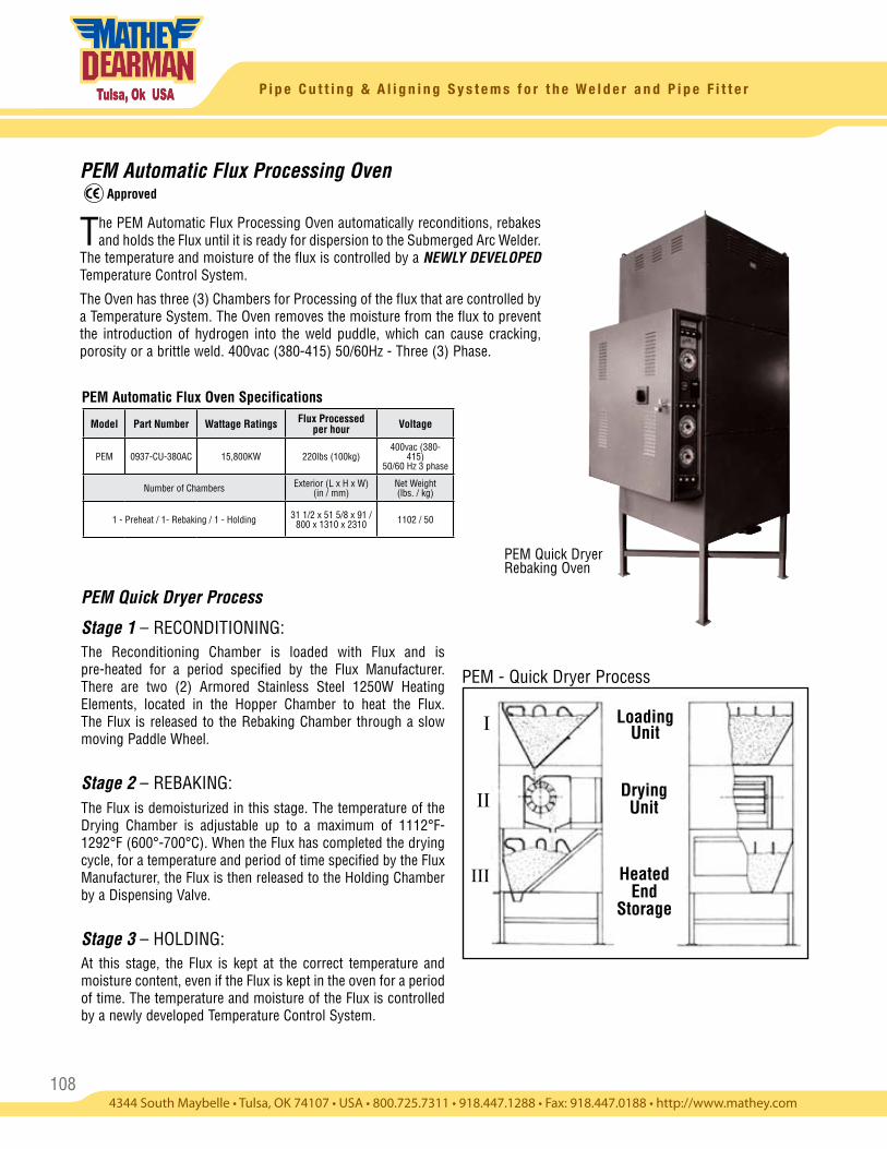
108
P i p e C u t t i n g & A l i g n i n g S y s t e m s f o r t h e W e l d e r a n d P i p e F i t t e r
PEM Automatic Flux Processing Oven
The PEM Automatic Flux Processing Oven automatically reconditions, rebakes and holds the Flux until it is ready for dispersion to the Submerged Arc Welder.
The temperature and moisture of the flux is controlled by a NEWLY DEVELOPED Temperature Control System.
The Oven has three (3) Chambers for Processing of the flux that are controlled by a Temperature System. The Oven removes the moisture from the flux to prevent the introduction of hydrogen into the weld puddle, which can cause cracking, porosity or a brittle weld. 400vac (380-415) 50/60Hz - Three (3) Phase.
PEM - Quick Dryer Process
Loading Unit
Drying Unit
Heated End
Storage
I
III
II
PEM Quick Dryer Rebaking Oven
PEM Automatic Flux Oven Specifications
Approved
PEM Quick Dryer Process
Stage 1 – RECONDITIONING: The Reconditioning Chamber is loaded with Flux and is pre-heated for a period specified by the Flux Manufacturer. There are two (2) Armored Stainless Steel 1250W Heating Elements, located in the Hopper Chamber to heat the Flux. The Flux is released to the Rebaking Chamber through a slow moving Paddle Wheel.
Stage 2 – REBAKING: The Flux is demoisturized in this stage. The temperature of the Drying Chamber is adjustable up to a maximum of 1112°F-1292°F (600°-700°C). When the Flux has completed the drying cycle, for a temperature and period of time specified by the Flux Manufacturer, the Flux is then released to the Holding Chamber by a Dispensing Valve.
Stage 3 – HOLDING: At this stage, the Flux is kept at the correct temperature and moisture content, even if the Flux is kept in the oven for a period of time. The temperature and moisture of the Flux is controlled by a newly developed Temperature Control System.
Model Part Number Wattage Ratings Flux Processed per hour Voltage
PEM 0937-CU-380AC 15,800KW 220lbs (100kg)400vac (380-
415) 50/60 Hz 3 phase
Number of Chambers Exterior (L x H x W)(in / mm)
Net Weight(lbs. / kg)
1 - Preheat / 1- Rebaking / 1 - Holding 31 1/2 x 51 5/8 x 91 / 800 x 1310 x 2310 1102 / 50
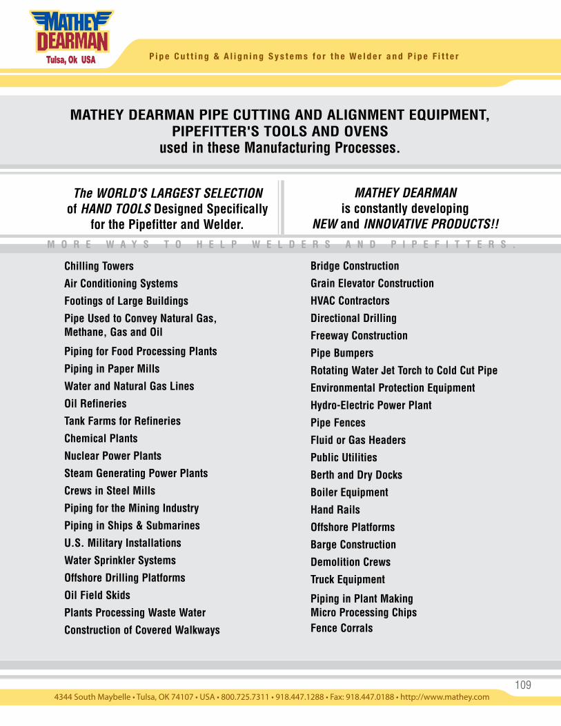
109
P i p e C u t t i n g & A l i g n i n g S y s t e m s f o r t h e W e l d e r a n d P i p e F i t t e r
The WORLD'S LARGEST SELECTION of HAND TOOLS Designed Specifically
for the Pipefitter and Welder.
MATHEY DEARMAN is constantly developing
NEW and INNOVATIVE PRODUCTS!!
Chilling Towers
Air Conditioning Systems
Footings of Large Buildings
Pipe Used to Convey Natural Gas, Methane, Gas and Oil
Piping for Food Processing Plants
Piping in Paper Mills
Water and Natural Gas Lines
Oil Refineries
Tank Farms for Refineries
Chemical Plants
Nuclear Power Plants
Steam Generating Power Plants
Crews in Steel Mills
Piping for the Mining Industry
Piping in Ships & Submarines
U.S. Military Installations
Water Sprinkler Systems
Offshore Drilling Platforms
Oil Field Skids
Plants Processing Waste Water
Construction of Covered Walkways
M O R E W A Y S T O H E L P W E L D E R S A N D P I P E F I T T E R S .
MATHEY DEARMAN PIPE CUTTING AND ALIGNMENT EQUIPMENT, PIPEFITTER'S TOOLS AND OVENS
used in these Manufacturing Processes.
Bridge Construction
Grain Elevator Construction
HVAC Contractors
Directional Drilling
Freeway Construction
Pipe Bumpers
Rotating Water Jet Torch to Cold Cut Pipe
Environmental Protection Equipment
Hydro-Electric Power Plant
Pipe Fences
Fluid or Gas Headers
Public Utilities
Berth and Dry Docks
Boiler Equipment
Hand Rails
Offshore Platforms
Barge Construction
Demolition Crews
Truck Equipment
Piping in Plant Making Micro Processing ChipsFence Corrals
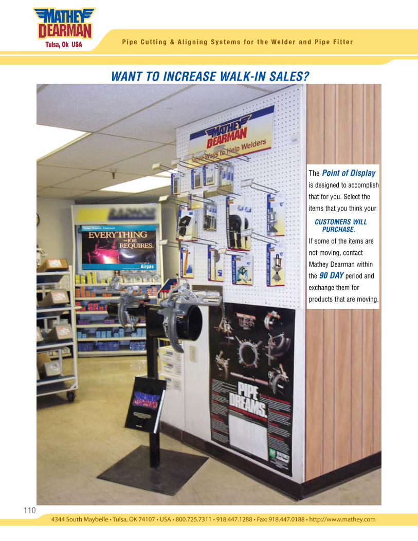
110
P i p e C u t t i n g & A l i g n i n g S y s t e m s f o r t h e W e l d e r a n d P i p e F i t t e r
WANT TO INCREASE WALK-IN SALES?
The Point of Display
is designed to accomplish
that for you. Select the
items that you think your
CUSTOMERS WILL PURCHASE.
If some of the items are
not moving, contact
Mathey Dearman within
the 90 DAY period and
exchange them for
products that are moving.
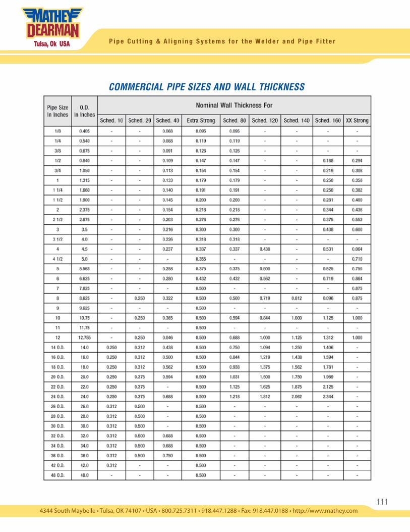
111
P i p e C u t t i n g & A l i g n i n g S y s t e m s f o r t h e W e l d e r a n d P i p e F i t t e r
COMMERCIAL PIPE SIZES AND WALL THICKNESS
112
P i p e C u t t i n g & A l i g n i n g S y s t e m s f o r t h e W e l d e r a n d P i p e F i t t e r
Mathey Dearman, Inc. and C.I.A. Mathey, Inc. Warranty and Terms and Conditions of SaleLIMITED WARRANTY Subject to the provisions contained herein, if any merchandise sold hereunder (except merchandise manufactured by other persons or firms) by Mathey Dearman, Inc. ("Mathey Dearman") or C.I.A. Mathey, Inc. ("CIA Mathey"), (either as the seller of the merchandise sometimes referred to herein as the “Company”) is not in accordance with specifications shown on the order within customarily accepted tolerances, or is defective on account of workmanship or material, and if such merchandise is returned at the customer’s expense and risk, to the Company’s manufacturing facility (or at the Company’s option, is returned to a repair facility authorized by the Company), within ninety (90) days after the Company’s date of shipment thereof (the "Warranty Period"), the Company will, at its option, replace or repair the merchandise. This warranty, however, is subject to the conditions: (A) that the customer promptly notifies the Company in writing of any claim under this agreement, setting forth in detail any such claimed defect, and (B) That the Company be afforded a reasonable opportunity to examine the merchandise and to investigate and verify the claimed defect at the Company’s manufacturing facility or at an authorized repair facility. The Company shall not be, in any event, liable for damages beyond the price paid by the customer for such defective merchandise. THE COMPANY SHALL NOT BE LIABLE to CUSTOMER UNDER ANY THEORY OR CIRCUMSTANCES FOR CONSEQUENTIAL, INCIDENTAL, INDIRECT, PUNITIVE, OR EXEMPLARY DAMAGES. This agreement does not obligate the Company to bear any transportation charges in connection with the replacement or the repair of defective merchandise. As to any item manufactured by other persons or firms, the Company agrees to present a request for adjustment for repair to such manufacturer, and the customer agrees that the liability of the Company shall not exceed any adjustment with respect to which such manufacturer accepts responsibility. THE ABOVE AGREEMENT IS IN LIEU OF ALL WARRANTIES, EXPRESSED OR IMPLIED AND IT IS AGREED THAT THERE IS NO EXPRESSED OR IMPLIED WARRANTY BY THE COMPANY AS TO THE MERCHANDISE'S FITNESS FOR A PARTICULAR PURPOSE, MERCHANTABILITY, CAPACITY, OR EFFICIENCY AND THAT THERE ARE NO ORAL OR WRITTEN EXPRESSED OR IMPLIED WARRANTIES MADE IN CONNECTION WITH ANY SALE BY THE COMPANY OTHER THAN AS EXPRESSED HEREIN. No modification or addition to this agreement, either before or after the contract of sale, shall be made except on written authority of the President or Vice President of the Company. The Company shall have no liability for warranty claims if the merchandise has been abused, misused, vandalized, or operated beyond its specifications after delivery. Further, the Company shall also have no liability for Warranty Claims if the merchandise is from the Company's CGM Pipe Cutting and Beveling product line and has been used in any manner not in compliance with the “Conditions of Use”, as applicable.
Force MajeureThe Company shall not be liable for any delay in shipments or impairment of the performance of products resulting in total or in part from Acts of God, labor disruptions, laws, inability to procure product, shortages of supplies or raw materials, civil war or other act of hostility, acts of terrorism, civil unrest, or any other circumstances beyond the reasonable control of the Company.
QuotationsQuick and accurate quotations on orders of any size are available upon request. Please contact Mathey Dearman, Inc. Sales Department 1 (800) 725-7311, (918) 447-1288, fax (918) 447-0188 or e-mail us at: [email protected].
Technical SupportOur knowledgeable and skilled staff is eager to assist you in your search for solutions. Please contact Mathey Dearman, Inc. Sales Department 1 (800) 725-7311 or (918) 447-1288, Central Standard Time.
Catalog ErrorsAll information in the catalogue has been carefully checked for accuracy. Errors and omissions occasionally occur and therefore are subject to correction and/or change and we regret any inconvenience this may cause.
Terms and Billing OptionsNet 30 days on approved open account from date of invoice. In addition to open accounts, we accept cash, C.O.D., wire transfer, letter of credit confirmed on U.S. Bank and credit card (Visa, MasterCard, American Express).
CancellationAny cancellation of orders must be approved by the Company and may be subject to restocking and/or other charges.
Sales TaxSales tax is the responsibility of the customer unless a valid exemption certificate is on file with the Company prior to the placement of an order.
Freight PolicyUnless otherwise stated, freight and shipping fees will be charged on shipments to a customer’s place of business anywhere in the contiguous United States, using a carrier of the customer’s choice. Other terms apply to Alaska, Hawaii, Puerto Rico, and export orders. Any extra charges incurred for additional services and special handling by the customer’s carrier must be paid by the consignee. Title and risk of loss will pass to the customer upon tender of the shipment to the carrier. If the product is damaged in transit, Consignee must file the claim with the carrier.
If consignee is responsible for the freight do not return the damaged product to the Company without filing the freight claim,
Returns and Warranty RepairsReturnsTo return products for credit or warranty repair, you must first contact Mathey Dearman Inc. at (918) 447-1288 for a Return Goods Authorization (RGA) Number. No returns will be accepted without a RGA number. Please print the RGA number on the outside of the box and include a copy of your invoice or packing with the returned product. Product must be packed properly. Any damages due to improper packing will be the responsibility of the shipper. Merchandise is subject to a restocking charge.
Any claims for discrepancies in shipment must be made within 7 days of receipt of merchandise. C.O.D. returns will not be accepted. The Company will not accept product returned for credit that have been painted, etched or altered.
-1-
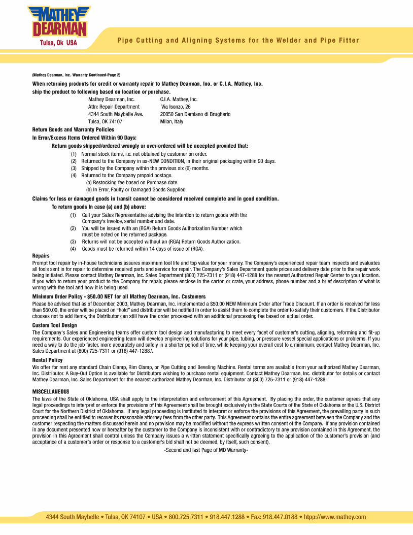
Related Documents