Mathematical models and numerical simulations of a thermally expandable microballoon for plastic foaming Masayasu Fujino a , Takashi Taniguchi a , Yasuhiro Kawaguchi b , Masahiro Ohshima a,n a Department of Chemical Engineering, Kyoto University, Kyoto 615-8510, Japan b Technical Section, Polymer production Department, Tokuyama Sekisui CO. LTD., Yamaguchi 746-0006, Japan HIGHLIGHTS A mathematical model of polymeric microballoon was developed to simulate the expansion behavior of a microballoon in air and in a polymer matrix. The viscoelastic properties of polymeric microballoon were taken into account in the model. The developed model showed quite good agreement with the observed thermal expansion behavior of a microballoon. article info Article history: Received 23 April 2013 Received in revised form 1 September 2013 Accepted 3 September 2013 Available online 10 September 2013 Keywords: Microballoon Microsphere Expandability Mathematical modeling Polymer processing Viscoelasticity abstract Thermally expandable microcapsules, often called microspheres or microballoons, are utilized in compression, injection molding and extrusion processes to foam different types of polymers. Micro- balloons consist of a polymer shell and a liquid hydrocarbon core. Hydrocarbons are used as a physical blowing agent. In this study, a mathematical model was developed to describe the expansion behavior of a microballoon in air and in a polymer matrix. The model was used to determine the key factors in improving the expandability of the balloon at designated temperatures. The viscoelastic properties of the polymer shell, evaporation of hydrocarbons in the balloon and diffusion behavior of the blowing agent through the polymer shell were taken into account in the model. The results of the developed model showed quite good agreement with the experimentally observed thermal expansion behavior of a microballoon. A sensitivity analysis of the expansion behavior with respect to the properties of the microballoon was also conducted to devise an optimal design strategy for high-expansion microballoons. & 2013 Elsevier Ltd. All rights reserved. 1. Introduction Recently, requirements for further reducing the weight of plastic parts, especially automotive parts for mileage improve- ment, have been established. Plastic parts other than those used in the automotive industry also require a reduction in weight with- out deteriorating their mechanical properties and appearance. Polymer foaming is one of the most promising techniques for realizing weight reduction. Polymer foaming methods can be roughly divided into two groups: chemical foaming and physical foaming. Chemical foaming uses chemicals that release gas, such as carbon dioxide (CO 2 ) and nitrogen (N 2 ), by thermal decomposi- tion. The released gas dissolves into the polymer or directly leads to bubble expansion and the formation of a cellular structure. Physical foaming does not involve any chemical reaction. It simply uses butane, pentane, CO 2 or N 2 as a blowing agent. Thermally expandable microballoons are used in physical foaming, in which polymeric capsules are used to foam polymers. A low-boiling-point hydrocarbon liquid, such as octane or pen- tane, is encapsulated by a polymeric shell. By mixing microbal- loons with a thermoplastic polymer and allowing them to thermally expand, the polymers can be foamed. When microbal- loons are heated, they expand to 50–100 times their initial volumes. The polymeric microballoon was originally developed by Dow Chemical Co. (Morehouse and Tetreault, 1964) and has been advanced by others (Lundqvist, 1992; Yokomizo et al., 1997). Nowadays, microballoons are available in a variety of grades (Jonsson, 2006), and have been used in car parts (Mae, 2008a, 2008b), shoe sole production, vinyl plastisol formulations (Ahmad, 2001), as well as the rotational molding of linear low-density polyethylene and ethylene-vinyl acetate (Takacs et al., 2002; D'Agostino et al., 2003). Even though there a large number of patents and application reports have been issued, scientific papers, which discussed the synthesis and properties of the microballoon, have been still limited. In the early stage, the researches on Contents lists available at ScienceDirect journal homepage: www.elsevier.com/locate/ces Chemical Engineering Science 0009-2509/$ - see front matter & 2013 Elsevier Ltd. All rights reserved. http://dx.doi.org/10.1016/j.ces.2013.09.010 n Corresponding author. Tel.: þ81 75 383 2666. E-mail address: [email protected] (M. Ohshima). Chemical Engineering Science 104 (2013) 220–227

Welcome message from author
This document is posted to help you gain knowledge. Please leave a comment to let me know what you think about it! Share it to your friends and learn new things together.
Transcript
Mathematical models and numerical simulations of a thermallyexpandable microballoon for plastic foaming
Masayasu Fujino a, Takashi Taniguchi a, Yasuhiro Kawaguchi b, Masahiro Ohshima a,n
a Department of Chemical Engineering, Kyoto University, Kyoto 615-8510, Japanb Technical Section, Polymer production Department, Tokuyama Sekisui CO. LTD., Yamaguchi 746-0006, Japan
H I G H L I G H T S
� A mathematical model of polymeric microballoon was developed to simulate the expansion behavior of a microballoon in air and in a polymer matrix.� The viscoelastic properties of polymeric microballoon were taken into account in the model.� The developed model showed quite good agreement with the observed thermal expansion behavior of a microballoon.
a r t i c l e i n f o
Article history:Received 23 April 2013Received in revised form1 September 2013Accepted 3 September 2013Available online 10 September 2013
Keywords:MicroballoonMicrosphereExpandabilityMathematical modelingPolymer processingViscoelasticity
a b s t r a c t
Thermally expandable microcapsules, often called microspheres or microballoons, are utilized incompression, injection molding and extrusion processes to foam different types of polymers. Micro-balloons consist of a polymer shell and a liquid hydrocarbon core. Hydrocarbons are used as a physicalblowing agent. In this study, a mathematical model was developed to describe the expansion behavior ofa microballoon in air and in a polymer matrix. The model was used to determine the key factors inimproving the expandability of the balloon at designated temperatures. The viscoelastic properties of thepolymer shell, evaporation of hydrocarbons in the balloon and diffusion behavior of the blowing agentthrough the polymer shell were taken into account in the model. The results of the developed modelshowed quite good agreement with the experimentally observed thermal expansion behavior of amicroballoon. A sensitivity analysis of the expansion behavior with respect to the properties of themicroballoon was also conducted to devise an optimal design strategy for high-expansion microballoons.
& 2013 Elsevier Ltd. All rights reserved.
1. Introduction
Recently, requirements for further reducing the weight ofplastic parts, especially automotive parts for mileage improve-ment, have been established. Plastic parts other than those used inthe automotive industry also require a reduction in weight with-out deteriorating their mechanical properties and appearance.Polymer foaming is one of the most promising techniques forrealizing weight reduction. Polymer foaming methods can beroughly divided into two groups: chemical foaming and physicalfoaming. Chemical foaming uses chemicals that release gas, suchas carbon dioxide (CO2) and nitrogen (N2), by thermal decomposi-tion. The released gas dissolves into the polymer or directly leadsto bubble expansion and the formation of a cellular structure.Physical foaming does not involve any chemical reaction. It simplyuses butane, pentane, CO2 or N2 as a blowing agent.
Thermally expandable microballoons are used in physicalfoaming, in which polymeric capsules are used to foam polymers.A low-boiling-point hydrocarbon liquid, such as octane or pen-tane, is encapsulated by a polymeric shell. By mixing microbal-loons with a thermoplastic polymer and allowing them tothermally expand, the polymers can be foamed. When microbal-loons are heated, they expand to 50–100 times their initialvolumes.
The polymeric microballoon was originally developed by DowChemical Co. (Morehouse and Tetreault, 1964) and has beenadvanced by others (Lundqvist, 1992; Yokomizo et al., 1997).Nowadays, microballoons are available in a variety of grades(Jonsson, 2006), and have been used in car parts (Mae, 2008a,2008b), shoe sole production, vinyl plastisol formulations (Ahmad,2001), as well as the rotational molding of linear low-densitypolyethylene and ethylene-vinyl acetate (Takacs et al., 2002;D'Agostino et al., 2003). Even though there a large number ofpatents and application reports have been issued, scientific papers,which discussed the synthesis and properties of the microballoon,have been still limited. In the early stage, the researches on
Contents lists available at ScienceDirect
journal homepage: www.elsevier.com/locate/ces
Chemical Engineering Science
0009-2509/$ - see front matter & 2013 Elsevier Ltd. All rights reserved.http://dx.doi.org/10.1016/j.ces.2013.09.010
n Corresponding author. Tel.: þ81 75 383 2666.E-mail address: [email protected] (M. Ohshima).
Chemical Engineering Science 104 (2013) 220–227

polymeric microballoons were directed to the investigations of theeffects of the existing microballoons on mechanical property of thefoam (Lawrence et al., 2001; Mae, 2008a, 2008b; Gupta andWoldensenbet, 2004). Recently, some papers related to synthesisand expandability of the balloons (Kawaguchi and Oishi, 2004;Kawaguchi et al., 2005) developed a thermally expandable micro-balloon for foaming polypropylene (PP) that required high proces-sing temperatures above 200 1C. This temperature range cannot beaccommodated by conventional thermally expandable microcap-sules. Jonsson et al. (2009, 2010) synthesized the microballoonsand investigated the relation among their expandability, balloonsize and the structure of crosslinker. Kawaguchi et al. (2010, 2011)consecutively investigated the expansion behavior of a conven-tional microballoon by visual inspection and developed a mathe-matical model for designing a new type of capsule. Their modelconsisted of Newtonian constitutive equation and equations forthe diffusion and evaporation of the blowing agent. The modelshows fairly good but not complete agreement with experimentaldata. In particular, the elastic behavior of the balloon could not besimulated by the researchers' model.
In this study, the microballoon model was re-designed byconsidering the viscoelastic behavior of the shell to improve thepredictability of the microballoon's expansion behavior both in air(free expansion) and in a polymer matrix.
2. Mathematical models of microballoon
2.1. Assumption for model development
A mathematical model was developed to describe the expan-sion behavior of a microballoon both in air and in a polymermatrix. It was considered that the expansion behavior comprisesthree basic phenomena: (1) deformation (expansion) of the poly-meric shell, (2) evaporation of the liquid hydrocarbon blowingagent and establishment of a vapor pressure in the microballoonand (3) diffusion of the hydrocarbon blowing agent from the insideto the outside of the balloon.
Microscopy images of a microballoon before and after expan-sion are illustrated in Fig. 1. From these images, a simple micro-balloon structure was constructed to have three majorcomponents: (1) a polymeric shell (outer layer), (2) a hydrocarbonliquid layer (middle layer) and (3) a hydrocarbon gas phase (innerlayer), as illustrated in Fig. 2.
To develop a microballoon model, the following assumptionswere made for the abovementioned microballoon structure:
(a) The balloon expands uniformly along the radial direction. Inother words, the radius of the balloon changes while main-taining the balloon's spherical shape.
(b) The polymeric shell is deformed uniformly along the radialdirection only without any degradation (reactions) or breakup.The polymer properties are not altered by expansion.
(c) The change in the density of the polymer shell with tempera-ture is negligible.
(d) The heat transfer in the balloon is so fast that the temperatureof the balloon can be considered to be uniform and equal tothe temperature of the surrounding media.
(e) The effect of inertia on the deformation and fluidization of thepolymeric shell is negligible because of the low Reynoldsnumber: because the radius of the balloon is several micro-meters and the viscosity of polymer is high, the Reynoldsnumber could be considered to be low.
(f) There is no stress distribution in the polymer shell. The stressin the shell is uniform.
(g) The shell polymer and the matrix polymer are viscoelastic andincompressible.
(h) The blowing agents satisfy the ideal gas law.(i) The permeability of the liquid in the shell polymer is negligible
compared with that of the gas. Only the permeability of thegaseous blowing agent in the shell polymer is considered.
(j) The driving force of the permeability of the gas in thepolymeric shell is governed by the difference in the partialpressures of the blowing agent inside and outside of theballoon.
With these assumptions, three basic equations, i.e., an equationof continuity, a momentum balance equation and the materialbalance equation of the blowing agent, were developed using aconstitutive viscoelastic equation and the ideal gas law.
2.2. Model equations of free expansion in air
In the developmental stage of a microballoon, the expandabil-ity of the microballoon is experimentally tested in free-expansionmode: a specified number of microballoons are placed in atemperature-controlled transparent vessel, the vessel is heatedto expand the balloons at a given temperature under atmosphericpressure and the volumetric change before and after expansion ismeasured. Therefore, we first developed a model of an isolatedmicroballoon suspended in air to describe the expansion behaviorduring the course of heating.
2.2.1. Equation of continuityWith the assumption of the incompressibility of the shell
polymer (g), the equation of continuity of the polymer is given by
∇Uv¼ 0 ð1ÞFig. 1. Microscopic images of microballoon (a) before expansion and (b) afterfoaming.
Fig. 2. Schematic structure of microballoon.
M. Fujino et al. / Chemical Engineering Science 104 (2013) 220–227 221

Using spherical coordinates (r; θ;ϕ) and invoking assumption (b),the velocity of deformation or flow can be described by
vðr; tÞ ¼ ervrðr; tÞ ðRinðtÞrrrRexðtÞÞ ð2Þwhere vðr; tÞ is the velocity of the polymer at position r : ¼ ðr; θ;ϕÞand time t. vrðr; tÞ is the radial component of the velocity at aradius r and at a time t. er is the unit vector along the radialdirection. Rin(t) and Rex(t) denote the inner radius of the polymershell and the radius of the microballoon (outer radius), respec-tively, at time t, as illustrated in Fig. 2.
Because the shell polymer is incompressible (assumption (g)),vrðr; tÞ satisfies1r2
∂∂rðr2vrÞ ¼ 0 ð3Þ
Taking the integral of Eq. (3), vrðr; tÞ can be expressed as anr-independent function F(t):
vrðr; tÞ ¼FðtÞr2
ð4Þ
Using the expressions vrðRin; tÞ ¼ _RinðtÞ and vrðRex; tÞ ¼ _RexðtÞ, F(t)can be derived from Eq. (4):
FðtÞ ¼ R2inðtÞ _RinðtÞ ¼ R2
exðtÞ _RexðtÞ ð5Þ
In the above expressions and hereafter, the dot on a variabledenotes the time derivative of the variable. Denoting the thicknessof the polymeric shell by h (i.e., Rex ¼ Rinþh) and assuming thatRin44h is satisfied, Eq. (6) can be derived from Eq. (5) byneglecting the higher-order terms of h (i.e., h2, h3,….,):
_hðtÞhðtÞ ¼ �2
_RinðtÞRinðtÞ
ð6Þ
Integrating Eq. (6) yields
hðtÞR2inðtÞ ¼ V0 ð7Þ
where V0 is a constant volumetric parameter.By introducing an expansion ratio, λðtÞ � RinðtÞ=Rð0Þ
in , Eq. (7) canbe rewritten as follows:
hðtÞ ¼ hð0Þλ�2ðtÞ ð8Þwhere the superscript (0) indicates the initial value of the variable.
Eq. (8) is the equation of continuity for describing changes inthe radius and thickness of the polymer shell.
2.2.2. Momentum balance equationsThe momentum balance equation for a microballoon is as
follows:
ρs∂v∂t
þðvU∇Þv� �
¼�∇pþ∇Ur ð9Þ
where ρs; p; r are the density, pressure and stress of the shellpolymer, respectively.
By substituting Eqs. (2) and (4) into Eq. (9), the radial compo-nent of Eq. (9) is transformed into
ρsr2
_FðtÞ � 2F2ðtÞr3
" #¼� ∂p
∂rþ½∇Ur�r ð10Þ
Assumptions (a) and (b) lead to sθr ¼ 0 and sφr ¼ 0. Thus, theright-hand side of Eq. (10) can be rewritten as follows:
ρsr2
_FðtÞ � 2F2ðtÞr3
" #¼� ∂p
∂rþ∂srr
∂rþ2srr�sθθ�sφφ
rð11Þ
Integrating both sides of Eq. (11) with respect to r from Rin toRex gives
ρs � 1RexðtÞ
� 1RinðtÞ
� �_FðtÞþ 1
R4exðtÞ
� 1
R4inðtÞ
!F2ðtÞ2
" #
¼�pðRexÞþpðRinÞþsrrjr ¼ Rex�srr jr ¼ RinþZ Rex
Rin
2srr�sθθ�sφφr
� �dr
ð12Þ
The force balances at the inner and outer surfaces of thepolymeric shell are as follows:
At the inner surface
Pin ¼ pðRinÞ�srr��r ¼ Rin
þ 2γRin
¼ pðRinÞ�srr��r ¼ Rin
þ 2γ
Rð0Þin λ
ð13Þ
At the outer surface
pðRexÞ�srr��r ¼ Rex
¼ Poþ 2γRex
¼ Poþ 2γ
Rð0Þin λþhð0Þλ�2
ð14Þ
where Pin and Po, respectively, denote the pressure inside theballoon and that of the media (air or polymer) surrounding theballoon.
Using Rex ¼ Rinþh, Rinbh together with Eqs. (5) and (8), theright-hand side (RHS) of Eq. (12) can be simplified to
RHSffiρshðtÞR2inðtÞ
_FðtÞ � 2
R3inðtÞ
F2ðtÞ" #
¼ ρshð0ÞRð0Þ
in
€λðtÞλ2ðtÞ
Using the notation Δs� 2srr�sθθ�sφφ, taking the Taylor expan-sion and substituting Eq. (8), the last term of Eq. (12) (LT Eq. (12))can also be simplified to
LTEq:12¼Z Rex
Rin
Δsr
� �drffihð0Þ
Rð0Þin
Δsjr ¼ Rin
λ3
Then, neglecting the inertia, i.e.,ρPhð0ÞRð0Þ
in ð€λðtÞ=λ2ðtÞÞ, Eq. (12) isfinally transformed into
0¼ Pin�Po�2γ1
Rð0Þin λ
þ 1
Rð0Þin λþhð0Þλ�2
!þhð0Þ
Rð0Þin
Δsjr ¼ Rin
λ3ð15Þ
The stress difference in Eq. (15), Δs, can be calculated by thefollowing constitutive equation for a viscoelastic shell polymer.
2.2.3. Constitutive equation (stress–deformation)The viscoelasticity of the shell polymer is described by the
upper convective Maxwell model:
rþτr∇ ¼ 2ηD ð16Þ
where, r∇ ¼ _rþðvU∇Þr�ð∇vÞUr�rUð∇vÞT. r is the stress tensor, andη is the shear viscosity. G is the shear elastic modulus τ¼ η=G is therelaxation time. D is the deformation rate tensor, and ∇v is thevelocity gradient tensor. The temperature dependences of G,η and τ are addressed by the Arrhenius type equationsG¼ AG expðBo=TÞ and τ¼ Aτ expðBτ=TÞ. T is the temperature ofthe microballoon.
Assuming that no stress exists in the balloon shell beforeexpansion (assumption (f)), rearranging Eq. (16) using Eq. (5) givesthe following equation for each element of Eq. (16)
dsrrdt
¼�4ðsrrþGÞ_λ
λ� srr
τ
dsθθdt
¼ 2ðsθθþGÞ_λ
λ� sθθ
τð17Þ
M. Fujino et al. / Chemical Engineering Science 104 (2013) 220–227222

dsφφdt
¼ 2ðsφφþGÞ_λ
λ� sφφ
τ
Then, Δs can be calculated by
dΔsdt
¼ ð2Δs�12srr�12GÞ_λ
λ� Δs
τð18Þ
2.2.4. Material balances of blowing agentA mixture of hydrocarbons is often used as the blowing agent.
The model was developed to accommodate not only single butalso multiple hydrocarbon components. From assumption (h), thepressure inside the microballoon is established by the vaporpressure of the hydrocarbon and can be determined by
Pin ¼∑kPk ¼∑
k
myk
MkRT
4π3R3gas
� ��1
ð19Þ
where Pk is the partial pressure of the kth component of theblowing agent.Mk is the molecular weight of the kth component ofthe blowing agent, and R is the universal gas constant. myk is themass of the blowing agent in the gas phase. Rgas is the radius of thegas phase in the microballoon, as illustrated in Fig. 2.
The total volume of the balloon core should be equal to the sumof the volumes of the gas and liquid phases, as shown in Fig. 2
4π3Rð0Þ3in λ3 ¼ 4π
3R3gasþ∑
k
mxk
ρLkð20Þ
where ρLk is the liquid density of the kth component of theblowing agent and mxk is the mass of the kth component of theblowing agent in the liquid phase.
The evaporation rate is a function of the saturation pressure,Psat, of the blowing agent at temperature T:
dmxk
dt¼�4πR2
gaskm;kðPsat;k�PkÞ ð21Þ
where km,k is the mass transfer coefficient of the kth component ofthe blowing agent. The saturation pressure,Psat;k, of the kth compo-nent of the blowing agent is temperature-dependent and is givenby the Antoine equation and Raoult's law (assumption (h)):
Psat;k ¼mxk=Mk
∑lðmxl=MlÞexp Ak�
Bk
TþCk
� �ð22Þ
where Ak, Bk and Ck are the property parameters of the kthcomponent of the blowing agent.
The blowing agent permeates the polymer shell and diffusesfrom the balloon after its liquid phase disappears (assumptions(i) and (j)). The mass flow rate from the inside to the outside of themicroballoon is given by
dmzk
dt¼ 4πRinðRinþhÞkp;k
hPk ¼ 4π
Rð0Þin
hð0ÞðRð0Þin λ4þhð0ÞλÞkp;kPk ð23Þ
where kp;k is the permeability coefficient and 4πRinðRinþhÞ is theaverage shell surface area. mzk is the weight of the blowing agentdiffusing from the balloon.
The total mass balance of the kth component of the blowingagent is given by
mxkþmykþmzk ¼mð0Þxk þmð0Þ
yk þmð0Þzk ð24Þ
2.3. Model equations of expansion in polymer
As mentioned before, the performance of a microballoon isoften evaluated by conducting an expansion test in air. However,in practice, the balloon is used by blending with thermoplasticpolymers to foam the polymers. Therefore, it is also important todevelop models describing the expansion behavior of a balloon in
a polymer matrix. The free-expansion models for a microballooncould be extended to describe the foaming behavior in a polymermatrix with some modifications of the momentum balance andmaterial balance equations.
2.3.1. Momentum balance equationsWhen the microballoon is placed in a polymer matrix, Eq. (11)
must be integrated over the range [Rin;Rex] for a microballoon andover the range [Rex;1] for the polymer matrix that surrounds themicroballoon.
0¼�psðRexÞþpsðRinÞþsrrsjr ¼ Rex�srrsjr ¼ Rin
þZ Rex
Rin
2srrs�sθθs�sφφsr
� �dr
ð25Þ
0 ¼�ppðr-1ÞþppðRexÞþsrrpjr-1�srrpjr ¼ RexþZ 1
Rex
2srrp�sθθp�sφφpr
� �dr
ð26Þ
where subscripts s and p stand for the variables related to shellpolymer and polymer surrounding the microballoon (matrixpolymer), respectively.
As a boundary condition, the force balances at the interfacebetween the balloon and matrix polymer and at the inner surfaceof the polymeric shell (i.e., interface between polymer and gas)are, respectively, given by
Pin ¼ psðRinÞ�srrs��r ¼ Rin
þ2γsRin
¼ psðRinÞ�srrs��r ¼ Rin
þ 2γsRð0Þin λ
ð27Þ
psðRexÞ�srrs��r ¼ Rex
¼ ppðRexÞ�srrpjr ¼ Rexþ2γsp
Rex
¼ ppðRexÞ�srrpjr ¼ Rexþ 2γspRð0Þin λþhð0Þλ�2
ð28Þ
where γs and γsp are the surface tension of the shell polymer andthe interfacial tension between the shell polymer and the matrixpolymer.
Considering that the pressure of the matrix polymer at bulkppðr-1Þ is constant, Po, the distance over which the polymer isdeformed is negligible, i.e., srrpjr-1 ¼ 0 at an infinite distance fromthe center of the balloon. Thus, the overall force balance around amicroballoon in a polymer matrix is given by
0¼ ðPin�PoÞ�2γsRin
þ2γspRex
� �þZ Rex
Rin
Δssr
� �drþ
Z 1
Rex
Δspr
� �dr ð29Þ
The constitutive equation for the shell polymer and that for thematrix polymer are, respectively, given by
dsrrdt
¼�4ðsrrþGÞ ðRð0Þin Þ3λ2 _λ
ζþðRð0Þin Þ3λ3
� srrτ
ð30Þ
dðΔsÞdt
¼ ð2Δs�12srr�12GÞ ðRð0Þin Þ3λ2 _λ
ζþðRð0Þin Þ3λ3
� Δsτ
ð31Þ
where ζ ¼ r3�R3in.
To calculate srr and Δs in the shell, ζ must be taken from 0 toR3ex�R3
in and G should be chosen as the shear elastic modulus of theshell polymer. To calculate srr and Δs in the matrix polymer usingEqs. (30) and (31), ζ is taken from R3
ex�R3in to infinity (a certain
distance in the simulation) and G and τ are chosen as the elasticmoduli of the matrix polymer. The temperature dependences of Gand τ for the matrix polymer are also obtained using Arrhenius-type equations: G¼ AGP expðBoP=TÞ and τ¼ AτP expðBτP=TÞ.
M. Fujino et al. / Chemical Engineering Science 104 (2013) 220–227 223
2.3.2. Material balances of blowing agentEqs. (18)–(22) and (24) can be applied to the case in which the
microballoon is placed in a polymer matrix. Eq. (23) should bemodified to calculate the concentration profiles of the blowingagent in the polymer matrix as well as the mass transfer of theagent by diffusion.
Assuming that the diffusion of the kth component of theblowing agent follows Fick's laws and does not affect the diffusionmechanisms of the other components, the following mass balanceequations are satisfied.
dzkdt
¼ ddt
Z 1
Rex
ð4πr2MkckÞdr¼�4πR2exDef f ;kMk
∂ck∂r
� �����r ¼ Rex
¼ 4πRexRinkpkhðPk�Pex;kÞ ð32Þ
where Def f ;k is the diffusion coefficient of the kth component of theblowing agent in the matrix polymer. Pex;k is the equilibriumpressure of the kth component of the blowing agent at theinterface between the shell polymer and the matrix polymer.
In this study, to reduce the calculation burden of simulation,the concentration profile of the kth component of the blowingagent at the outer surface of the shell was obtained by an integralapproximation (Rosner and Epstein, 1972) without solving thepartial differential equation of Fick's second law:
ck ¼ cR;kRex þ δ�r
δ
� �20
(RexrrrRexþδ
Rexþδrrð33Þ
where δ is a hypothetical thickness of the concentration profile. cRkis the equilibrium concentration of the kth component of theblowing agent at the interface between the shell polymer and thematrix polymer.
Based on the assumption that the blowing agent followsHenry's law (Eq. (34)), cRk is calculated as follows:
cRk ¼ Pex;kk�1H;k ð34Þ
where kH;k is Henry's constant.From Eqs. (32)–(34), the concentration gradient of the kth
component of the blowing agent is derived as follows:
∂ck∂r
� �����Rex
¼�2cRkRex
�1þffiffiffiffiffiffiffiffiffiffiffiffiffiffiffiffiffiffiffiffiffiffiffiffiffiffiffiffiffiffiffiffi1þ 3
2πMkR3ex
zkcRk
s !�1
ð35Þ
where cRk is the concentration of the kth component of theblowing agent at the interface between the shell polymer andsurrounding polymer.
As illustrated in Fig. 3, the mass balance is satisfied at theinterface between the shell polymer and the surrounding polymerfor each component of the blowing agent.
�4πR2exDef f ;kMk
∂ck∂r
� �����r ¼ Rex
¼ 4πRexRinkpkhðPk�Pex;kÞ ð36Þ
Pex;k can be calculated by solving the following algebraic equation,which is derived by substituting Eqs. (34) and (35) into (36).
2Pex;k
kH;kDef f ;kMk �1þ
ffiffiffiffiffiffiffiffiffiffiffiffiffiffiffiffiffiffiffiffiffiffiffiffiffiffiffiffiffiffiffiffiffiffiffi1þ 3kHk
2πMkR3ex
zkPex;k
s !�1
¼ RinkpkhðPk�Pex;kÞ ð35Þ
3. Visual observation experiments and simulation results
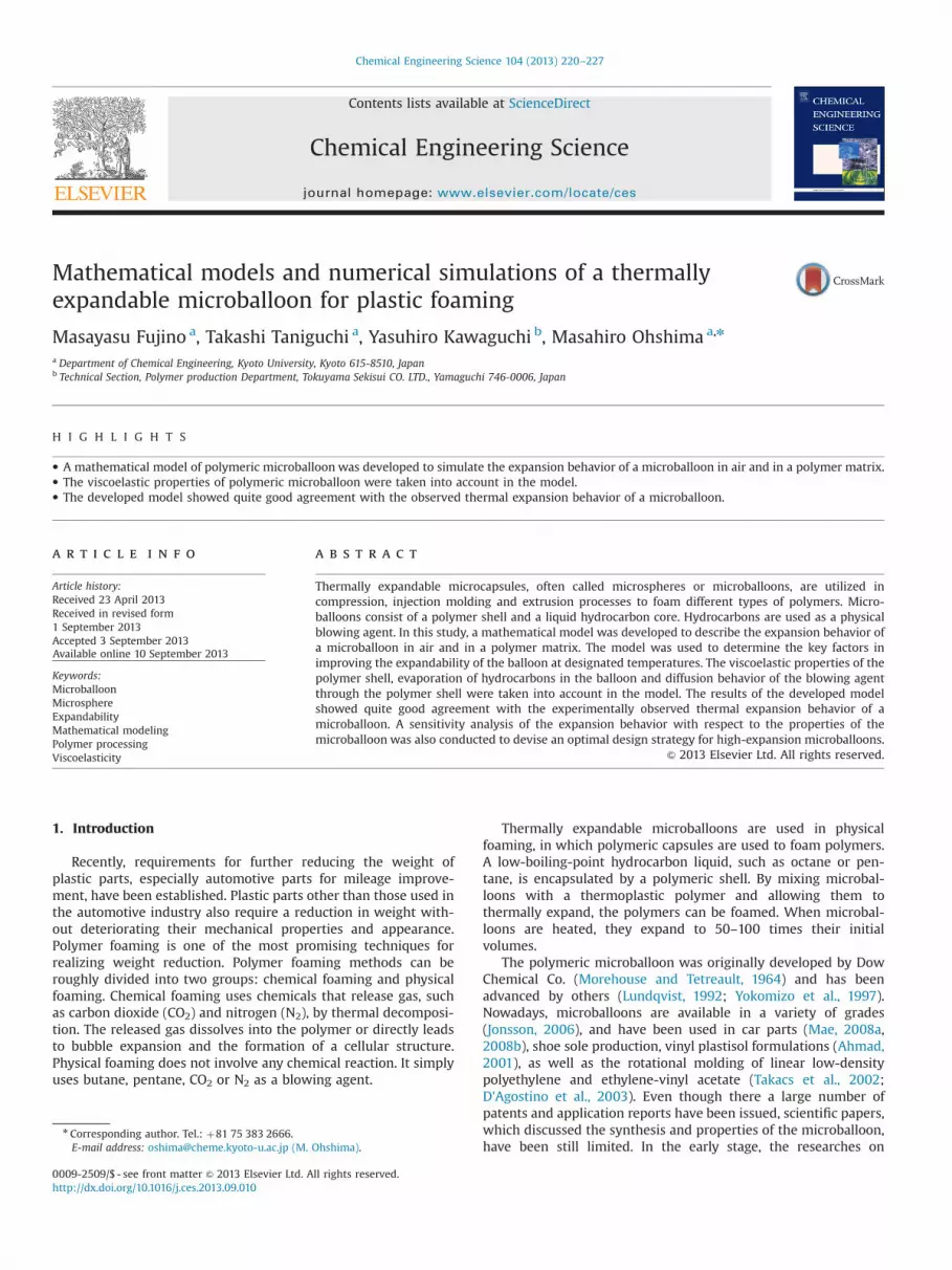
To determine the unknown parameters and confirm the pre-dictability of the developed models, an experiment performed byvisual inspection was conducted using the set-up illustrated inFig. 4.
A microballoon was placed in a view cell, which features twosapphire windows on both of its walls; the size of the cell is givenelsewhere (Taki et al., 2003). Then, the balloon was heated byelectrical heaters to a specified temperature. With the optical lightsource behind one of the windows, the expansion behavior of theballoon was observed through the other window by a high-speedcamera.
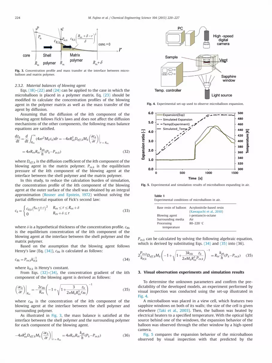
Fig. 5 compares the expansion behavior of the microballoonobserved by visual inspection with that predicted by the
Fig. 3. Concentration profile and mass transfer at the interface between micro-balloon and matrix polymer.
Fig. 4. Experimental set-up used to observe microballoon expansion.
Fig. 5. Experimental and simulation results of microballoon expanding in air.
Table 1Experimental conditions of microballoon in air.
Base resin of balloon Acrylonitrile-based resin(Kawaguchi et al., 2010)
Blowing agent i-pentane/n-octaneSurrounding media AirProcessing
temperature80–220 1C
M. Fujino et al. / Chemical Engineering Science 104 (2013) 220–227224

simulation. The experimental conditions are listed in Table 1. Thevisual observation experiments were conducted by heating anacrylonitrile-based microballoon in the view cell from 80 to220 1C. The blowing agent in the balloon was an 86:14 mixtureof i-pentane and n-octane. The black dotted line and the blacksolid line represent the temperature profile and the change in theradius of the expanding microballoon, respectively. The expansionratio was given by the ratio of the radius at time t to the initialradius of the microballoon.
The values of the model parameters are given in Table 2. In thesimulation, both hydrocarbon blowing agents had the same masstransport coefficients (km,1¼km,2) and permeability coefficients(kp;1 ¼ kp;2). The values of km,k and kp,k, and the rheologicalparameters, AG and Aτ, were determined such that the simulationcalculation would fit the experimental data as close as possible.Other parameters were obtained from the references. When theexpansion behavior was calculated, the experimentally-obtainedtemperature was approximated and simulated by a ramp functionand the simulated temperature was imposed to the simulationprogram.
Even though the fitting parameters were still needed, theexpansion behavior of the microballoon described by the devel-oped models was in good agreement with the observed behavior.In particular, the temperature at which the microballoon beganexpanding was exactly the same as that observed in the experi-ment. The elastic behavior of the expanding microballoon was alsoexpressed by the simulation. The shrinkage of the microballooninduced by gas escape was simulated even though there was adiscrepancy in the rate of shrinkage between the experiment andsimulation.
The discrepancy in shrinkage behavior might be caused by theincompleteness of modeling the diffusion process: in the real
process, a mass transfer of the liquid blowing agent in polymershell may occur, the phase transition of the blowing agent fromliquid to gas may occur in the polymer shell. In addition, thereplacement of the gaseous blowing agent with air might occur.Those phenomena could not be expressed by the present models.
Fig. 6 compares the expansion behavior of the microballoon ina polymer matrix observed by experiment with that described bythe simulation. The visual observation experiments were con-ducted by heating the same microballoon that we used in the free-expansion experiments (expansion in air). Most of the modelparameters describing the microballoon were the same as thosepresented in Table 2, except for the rheological properties. Therheological parameters of the matrix polymer (polystyrene) weretuned to make the simulated expansion behavior as close to theexperimental profile as possible. The resulting model parametersare listed in Table 3. The black and red solid lines represent theexperimental and simulated expansion behavior of the microbal-loon, respectively. Due to the presence of a matrix polymer, theexpansion behavior was suppressed and the shrinkage rate wasreduced to some extent compared with the expansion behavior inair. The simulation successfully described the observed expansionand shrinkage behaviors.
4. Sensitivity analysis
Using the developed model, a sensitivity analysis was con-ducted to determine the effect of elasticity, the relaxation time ofthe shell polymer, and the permeability of the blowing agent onthe expansion behavior. For the analysis, the mathematical modelof free expansion (in air) with a single-component blowing agent(pentane) was used. The values of the model parameters arepresented in Table 4. Fig. 7 shows the expansion behaviors ofthe balloon with the different elasticity of the shell polymer. Theballoon expansion ratio was defined by the ratio of the radius ofthe balloon at time t to the initial radius. As the elastic modulus ofthe shell polymer increased, the onset temperature of expansionwas shifted to higher temperatures and the degree of initialdeformation of the microballoon was reduced.
Furthermore, the maximum expansion ratio was increasedwith the increase in elastic modulus. These behaviors could beexplained in the following way: because of the increase in theonset temperature of expansion, the difference between insideand outside pressures at the onset, which is the driving force ofballoon growth, was increased and as a result, the degree of theballoon deformation (expansion) was increased.
Fig. 8 shows the effect of the relaxation time of the shellpolymer on microballoon expansion; the simulation was carriedout by changing the relaxation time τ of the shell polymer. Asshown, the temperature required to reach the maximum expan-sion ratio increased and the amplitude of the maximum expansionratio decreased as the relaxation time increased.
Table 2Simulation parameters (balloon in air).
Ambient pressure [kPa] 101.3 ρL [kg m�3] of octane 702.8Surface tension [Pa m] 0.018 Mw [kg mol�1]of octane 0.11423Initial radi Rin(0) [μm] 6.6 ρL [kg m�3] of pentane 626.38Initial h(0) [μm] 2.0 Mw [kg mol�1]of pentane 0.07215km, k [kg Pa�1 m�2 s�1] 1.0�10�7 Weight ratio of blowing agent to balloon [–] 0.3kp, k [kg Pa�1 m�1 s�1] 6.0�10–20 Pentane/octane ratio [–] 86:14AG of shell polymer G [Pa] 3.65�10–13 Aτ of shell polymer τ [s] 7.714�10�5
BG of shell polymer G [Pa] 20,139 Bτ of shell polymer τ [s] 6863.8A of Antoine Eq. of octane 205,778 A of Antoine Eq. of pentane 20.7261B of Antoine Eq. of octane 2896.28 B of Antoine Eq. of pentane 2477.07C of Antoine Eq. of octane 52.41 C of Antoine Eq. of pentane 39.94
Fig. 6. Experimental and simulation results of microballoon expanding in poly-styrene. (For interpretation of the references to color in this figure legend, thereader is referred to the web version of this article.)
M. Fujino et al. / Chemical Engineering Science 104 (2013) 220–227 225

Fig. 9 shows the effect of the permeability of the gaseousblowing agent in the shell polymer, kp,k, on the expansionbehavior. The simulation was carried out by changing the perme-ability of the blowing agent in the shell polymer. The effect of
the permeability was prominent. As the permeability increased,the maximum expansion ratio was reduced and the size of themicroballoon quickly decreased.
From the sensitivity analysis, the following microballoon designstrategy could be established: to increase the expansion tempera-ture, the elastic modulus of the shell polymer must be increased.To increase the maximum expansion ratio, the relaxation time andpermeability must be reduced. The permeability should bereduced to prevent the microballoon from shrinking quickly andmaintain the dimensional stability of the resulting foams.
5. Conclusions
A mathematical model was developed to describe the expan-sion behavior of a microballoon in air and in a polymer matrix.Because some of the physical properties of the microballoon, suchas the viscosity of the shell polymer, were not experimentallyavailable, estimates were used for the simulation. Those estimatesmay induce some discrepancy between the simulation and experi-mental results. However, the present model was able to describethe intrinsic expansion behavior of a microballoon. For example, as
Table 4Model parameter values for sensitivity analysis.
Base resin of balloon Acrylonitrile Blowing agent (BA) Pentane
Shell density.[kg m�3] 810 Pentane/octane ratio 100:0Temperature condition From 80 to 220 1C Mw[kg mol�1] pentane 0.07215Ambient pressure [kPa] 101.3 Weight ratio of BA 0.3Surface tens. [Pa m] 0.018 Liquid dens ρL [kg m�3] 626.38Initial radi Rin(0) [μm] 6.6 km,1 [kg Pa�1 m�2 s�1] 1.0�10�7
Initial h(0) [μm] 2.0 kp,1 [kg Pa�1 m�1 s�1] 6.0�10–20
AG of shell polymer G [Pa] 3.2843�10–13 Aτ of shell polymer τ [s] 3.857�10�5
BG of shell polymer G [Pa] 20,139 Bτ of shell polymer τ [s] 6863.8A of Antoine Eq. of pentane 20.7261 B of Antoine Eq. of pentane 2477.07C of Antoine Eq. of pentane 39.94
Fig. 7. Effect of elastic modulus of shell polymer on expansion behavior.
Fig. 8. Effect of relaxation time on expansion behavior.
Fig. 9. Effect of permeability on expansion behavior of microballoon.
Table 3Experimental conditions and simulation parameters (balloon in polymer).
Base resin of balloon Acrylonitrile Matrix polymer Polystyrene
Matrix polymer 0.018 Weight ratio of blowing agent 0.2Ambient press [kPa] 101.3 Temp [1C] 130–230Deff,k [m2 s�1] 1.0�10–13 Henry const. kH,1¼kH,2 1.0�10�2
AG of shell polymer G [Pa] 4.56�10–13 Aτ of shell polymer τ [s] 7.714�10�5
BG of shell polymer G [Pa] 20,139 Bτ of shell polymer τ [s] 6863.8AGp of matrix polymer G [Pa] 3.65�10–13 Aτ of matrix polymer τ [s] 7.714�10�5
BGp of matrix polymer G [Pa] 20,139 Bτ of matrix polymer τ [s] 6863.8δ [μm] 13 h (t)
M. Fujino et al. / Chemical Engineering Science 104 (2013) 220–227226

the relaxation time of the shell polymer increased, the amplitudeof the expansion ratio decreased and the expansion behavior wasdecelerated. Similar behavior was observed when the permeabilitycoefficient of the shell polymer increased. When the permeabilityof the blowing agent in the shell polymer increases, the shrinkageof the balloon becomes prominent. To reduce the degree ofshrinkage, crosslinking could be employed. However, crosslinkingalso increases the elastic modulus of the shell polymer andreduces the degree of initial expansion. The models are not perfectat the present stage but they can be used to optimize microballoondesign semi-quantitatively. For further improvements of thesimulation accuracy, the additional models are needed to describethe phenomena that air, N2 and CO2 diffuse into the expandingballoon from outside or surrounding polymer. The values ofphysical parameters adjusted for the simulation calculations mightbe different from the true values of the materials. To develop thesophisticated models and perform the simulation without fittingthe model parameters, the precise measurements of the physicalparameters, such as diffusion coefficients and mass transfercoefficients, are needed.
References
Ahmad, M., 2001. Flexible vinyl resiliency property enhancement with hollowthermoplastic microspheres. Vinyl and Additive Technology 7 (3), 156–161.
D'Agostino, D., Takacs, E., Vlachopoulos, J., 2003. The Effect of Coupling Agents onfoaming with Polymer Microsphere in Rotational Molding, SPE ANTEC Tech.Papers, 49, 1205–1208.
Gupta, N., Woldensenbet, E., 2004. Microballoon wall thickness effects on proper-ties of syntactic foams. Journal of Cellular Plastics 40, 461–480.
Jonsson, L., 2006. Expandable microspheres as foaming agent in thermoplastics,thermosets and elastomers, In: Proceedings of Blowing Agents and FoamingProcesses, May, Germany, Paper 3, pp. 1–8.
Jonsson, M., Nordin, O., Kron, A.-L., Malmstrom, E., 2010. Thermally expandablemicrospheres with excellent expansion characteristics at high temperature.Journal of Applied Polymer Science 117, 384–392.
Jonsson, M., Nystrom, D., Nordin, O., Malmstrom, E., 2009. Surface modification ofthermally expandable microspheres by grafting poly(glycidyl methacrylate)using ARGET ATRP. European Polymer Journal 45, 2374–2382.
Kawaguchi, Y., Oishi, T., 2004. Synthesis and properties of thermoplastic expand-able microspheres: the relation between crosslinking density and expandableproperty. Journal of Applied Polymer Science 93 (2), 505–512.
Kawaguchi, Y., Itamura, Y., Orimura, K., Oishi, T., 2005. Effects of the chemicalstructure on the heat resistance of thermoplastic expandable microspheres.Journal of Applied Polymer Science 96 (4), 1306–1312.
Kawaguchi, Y., Ohshima, M., Tanida, M., Ohishi, T., Ito, A., Sawa, T., 2011. Develop-ment of thermally expandable microcapsule and their mathematical models forpolymer foaming. Seikei-Kakou 23 (10), 627–635.
Kawaguchi, Y., Ito, D., Kosaka, Y., Okudo, M., Nakachi, T., Kake, H., Kim, J.K., Shikuma,H., Ohshima, M., 2010. Thermally expandable microcapsules for polymerfoaming—relationship between expandability and viscoelasticity. PolymerEngineering and Science 50 (4), 835–842.
Lawrence, E., Pyrz, R., 2001. Viscoelastic properties of polyethylene syntactic foamwith polymer microballoons. Polymers and Polymer Composites 9, 227–237.
Lundqvist, J., 1992, Eur. Pat. 0486 080 B1.Mae, H., 2008a. Tensile mechanical properties in PP/SEBS/microballoon composites
under impact loading. Journal of Achievements in Materials and ManufacturingEngineering 31 (2), 341–347.
Mae, H., 2008b. Relationship of mechanical properties between neat PP/SEBSblends and syntactic PP/SEBS foams with polymer microballoons. Journal ofthe Society of Materials Science 57 (12), 1253–1260.
Morehouse, D.S.J., Tetreault, R.J., 1964, US Pat. 3615972.Rosner, D.E., Epstein, M., 1972. Effects of interface kinetics, capillarity and solute
diffusion on bubble growth rates in highly supersaturated liquids. ChemicalEngineering Science 27 (1), 69–88.
Takacs, E., Vlachopoulos, J., Rosenbusch, C., 2002. Foaming with Microspheres inRotational Molding, SPEANTEC Tech. Papers, 48, pp. 1271–1275.
Taki, K., Nakayama, T., Yatsuzuka, T., Ohshima, M., 2003. Visual observations ofbatch and continuous foaming processes. Journal of Cellular Plastics 139 (2),155–169.
Yokomizo, T., Tanaka, K., Niinuma, K., 1997, Jpn Pat. 9 019 635.
M. Fujino et al. / Chemical Engineering Science 104 (2013) 220–227 227
Related Documents