Properties of Inconel 625 mesh structures grown by electron beam additive manufacturing F.A. List a,n , R.R. Dehoff a , L.E. Lowe a , W.J. Sames b a Oak Ridge National Laboratory, 1 Bethel Valley Rd., Oak Ridge, TN, USA b Texas A&M University, College Station, TX, USA article info Article history: Received 18 March 2014 Received in revised form 16 July 2014 Accepted 17 July 2014 Available online 27 July 2014 Keywords: Nickel based superalloys Inconel 625 Electron beam melting Additive manufacturing Mesh structures Mechanical characterization abstract Relationships between electron beam parameters (beam current, beam speed, and beam focus) and physical properties (mass, diameter, elastic modulus, and yield strength) have been investigated for Inconel 625 mesh cubes fabricated using an additive manufacturing technology based on electron beam melting. The elastic modulus and yield strength of the mesh cubes have been systematically varied by approximately a factor of ten by changing the electron beam parameters. Simple models have been used to understand these relationships. Structural anisotropies of the mesh associated with the layered build architecture have been observed and may contribute, along with microstructural anisotropies, to the anisotropic mechanical properties of the mesh. Knowledge of this kind is likely applicable to other metal and alloy systems and is essential to rapidly realize the full potential of this burgeoning technology. & 2014 Elsevier B.V. All rights reserved. 1. Introduction Mesh structures may be incorporated into mechanical designs to tailor a variety of physical properties including mass, surface area, modulus, strength, and both thermal and electrical transport properties. This can lead to improved performance and reduced cost. For certain applications, control of the spatial gradient of a physical property is desirable. An example of such an application is a porous biomedical bone implant [1–3], where the implant must both promote osseointegration and match the varying mechanical requirements of the surrounding bone tissue. For these applica- tions, precise, fine-scale control of mesh properties is generally advantageous. Additive manufacturing (AM) based on electron beam melting (EBM) of metal powder is a particularly versatile technique to fabricate metal mesh structures with both uniform and spatially graded properties. By dividing the three dimensional mesh into two dimensional layers and sequentially building each layer, the desired three dimensional structure can be approximated. For EBM, the scale over which spatial control of properties is attain- able is limited in part by (a) the lateral dimensions of the electron beam (i.e., beam size) and (b) the size of the starting metal powder particles. One challenge using EBM to build fine mesh structures near the limit where mesh size approaches either the beam size or the powder particle size is to understand the relationships between the build parameters used for each layer and the properties of the final mesh structure. Another challenge is to understand the consequences and limitations of the two dimensional layer-by- layer approximation for the three dimensional structure. This paper focusses on identifying and characterizing relationships between electron beam parameters (i.e., beam current, speed, and focus) and mesh properties for EBM of Inconel 625 for the fabrication of fine mesh structures. Simple physical models are presented to help rationalize and refine some of these relationships. 2. Experimental A commercial Arcam A2 EBM machine running version 3.2 SP2 control software was used to fabricate the mesh structures. A general description of the machine and its typical operation can be found elsewhere [4]. Rotary atomized powder ( 120/ þ 325 sieve size) with a composition of commercial Inconel alloy 625, was used for fabrication. The nominal spherical particle diameter for this commercial powder ranges from 44 to 120 μm. Mesh cubes were built, sixteen at one time, on a 150 150 10 mm 3 , 304L stainless steel start plate. Each cube had outside dimensions of approximately 30 30 30 mm 3 and is based on a tetrahedral, diamond structure, unit cell that is oriented such that (a) all struts of the mesh make an angle of 301 with planes parallel Contents lists available at ScienceDirect journal homepage: www.elsevier.com/locate/msea Materials Science & Engineering A http://dx.doi.org/10.1016/j.msea.2014.07.051 0921-5093/& 2014 Elsevier B.V. All rights reserved. n Corresponding author. Tel.: þ1 865 576 8020. E-mail address: [email protected] (F.A. List). Materials Science & Engineering A 615 (2014) 191–197

Welcome message from author
This document is posted to help you gain knowledge. Please leave a comment to let me know what you think about it! Share it to your friends and learn new things together.
Transcript
Properties of Inconel 625 mesh structures grown by electronbeam additive manufacturing
F.A. List a,n, R.R. Dehoff a, L.E. Lowe a, W.J. Sames b
a Oak Ridge National Laboratory, 1 Bethel Valley Rd., Oak Ridge, TN, USAb Texas A&M University, College Station, TX, USA
a r t i c l e i n f o
Article history:Received 18 March 2014Received in revised form16 July 2014Accepted 17 July 2014Available online 27 July 2014
Keywords:Nickel based superalloysInconel 625Electron beam meltingAdditive manufacturingMesh structuresMechanical characterization
a b s t r a c t
Relationships between electron beam parameters (beam current, beam speed, and beam focus) andphysical properties (mass, diameter, elastic modulus, and yield strength) have been investigated forInconel 625 mesh cubes fabricated using an additive manufacturing technology based on electron beammelting. The elastic modulus and yield strength of the mesh cubes have been systematically varied byapproximately a factor of ten by changing the electron beam parameters. Simple models have been usedto understand these relationships. Structural anisotropies of the mesh associated with the layered buildarchitecture have been observed and may contribute, along with microstructural anisotropies, to theanisotropic mechanical properties of the mesh. Knowledge of this kind is likely applicable to other metaland alloy systems and is essential to rapidly realize the full potential of this burgeoning technology.
& 2014 Elsevier B.V. All rights reserved.
1. Introduction
Mesh structures may be incorporated into mechanical designsto tailor a variety of physical properties including mass, surfacearea, modulus, strength, and both thermal and electrical transportproperties. This can lead to improved performance and reducedcost. For certain applications, control of the spatial gradient of aphysical property is desirable. An example of such an application isa porous biomedical bone implant [1–3], where the implant mustboth promote osseointegration and match the varying mechanicalrequirements of the surrounding bone tissue. For these applica-tions, precise, fine-scale control of mesh properties is generallyadvantageous.
Additive manufacturing (AM) based on electron beam melting(EBM) of metal powder is a particularly versatile technique tofabricate metal mesh structures with both uniform and spatiallygraded properties. By dividing the three dimensional mesh intotwo dimensional layers and sequentially building each layer, thedesired three dimensional structure can be approximated. ForEBM, the scale over which spatial control of properties is attain-able is limited in part by (a) the lateral dimensions of the electronbeam (i.e., beam size) and (b) the size of the starting metal powderparticles. One challenge using EBM to build fine mesh structures
near the limit where mesh size approaches either the beam size orthe powder particle size is to understand the relationships betweenthe build parameters used for each layer and the properties of thefinal mesh structure. Another challenge is to understand theconsequences and limitations of the two dimensional layer-by-layer approximation for the three dimensional structure. This paperfocusses on identifying and characterizing relationships betweenelectron beam parameters (i.e., beam current, speed, and focus) andmesh properties for EBM of Inconel 625 for the fabrication of finemesh structures. Simple physical models are presented to helprationalize and refine some of these relationships.
2. Experimental
A commercial Arcam A2 EBM machine running version 3.2 SP2control software was used to fabricate the mesh structures.A general description of the machine and its typical operationcan be found elsewhere [4]. Rotary atomized powder (�120/þ325sieve size) with a composition of commercial Inconel alloy 625,was used for fabrication. The nominal spherical particle diameterfor this commercial powder ranges from 44 to 120 μm.
Mesh cubes were built, sixteen at one time, on a 150�150�10 mm3, 304L stainless steel start plate. Each cube had outsidedimensions of approximately 30�30�30 mm3 and is based on atetrahedral, diamond structure, unit cell that is oriented such that(a) all struts of the mesh make an angle of 301 with planes parallel
Contents lists available at ScienceDirect
journal homepage: www.elsevier.com/locate/msea
Materials Science & Engineering A
http://dx.doi.org/10.1016/j.msea.2014.07.0510921-5093/& 2014 Elsevier B.V. All rights reserved.
n Corresponding author. Tel.: þ1 865 576 8020.E-mail address: [email protected] (F.A. List).
Materials Science & Engineering A 615 (2014) 191–197
to the cube faces and (b) the projections of all struts onto the facesof the cube are parallel to the face diagonal (see Fig. 1). Thediameters of all struts in the build model were approximately0.025 mm. The opposing faces of a cube are separated by eighttimes the unit cell dimension. Cubes were loaded into the build fileas separate models so that build parameters could be variedindividually for each of the sixteen cubes. A melt theme was usedfor all models with power analyze off, melt hatch disabled, a0.050 mm layer thickness, and a single outer contour. This themeresulted in (a) a single melting event for each strut within eachlayer and (b) strut dimensions determined by the electron beamparameters. The beam current, beam speed, and focus offsetcurrent for the outer contour were varied to determine the impactof these parameters on the mesh properties. For all cubes, the unitcell, the unit cell dimension, and the outside dimensions of thecube were constant. Specimens were prepared for microstructuralexamination by polishing to a 1 mm diamond finish followed byetching in a solution consisting of 45 mL HCl, 2.2 mL HNO3, 2.5 mLH2SO4 and 0.5 mL HF.
3. Results and discussion
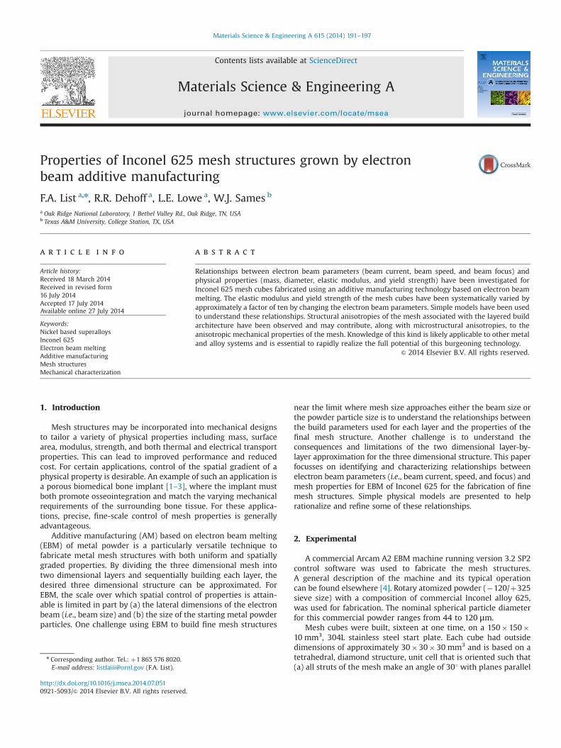
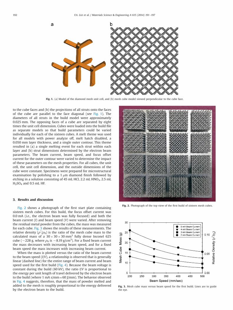
Fig. 2 shows a photograph of the first start plate containingsixteen mesh cubes. For this build, the focus offset current was0.0 mA (i.e., the electron beam was fully focused) and both thebeam current (I) and beam speed (V) were varied. After removingthe residual metal powder from the cubes, the mass was measuredfor each cube. Fig. 3 shows the results of these measurements. Therelative density (ρ*/ρ0) is the ratio of the mesh cube mass to thecalculated mass of a 30�30�30 mm3 fully dense Inconel 625cube (�228 g, where ρ0 is �8.19 g/cm3). For a fixed beam currentthe mass decreases with increasing beam speed, and for a fixedbeam speed the mass increases with increasing beam current.
When the mass is plotted versus the ratio of the beam currentto the beam speed (I/V), a relationship is observed that is generallylinear (dashed line) for the entire range of beam current and beamspeed used for the first build (Fig. 4). Because the beam voltage isconstant during the build (60 kV), the ratio I/V is proportional tothe energy per unit length of travel delivered by the electron beamto the build (where 1 mA s/mm¼60 J/mm). The behavior observedin Fig. 4 suggests, therefore, that the mass of powder melted andadded to the mesh is roughly proportional to the energy deliveredby the electron beam to the build.
Fig. 1. (a) Model of the diamond mesh unit cell, and (b) mesh cube model viewed perpendicular to the cube face.
Fig. 2. Photograph of the top view of the first build of sixteen mesh cubes.
Fig. 3. Mesh cube mass versus beam speed for the first build. Lines are to guidethe eye.
F.A. List et al. / Materials Science & Engineering A 615 (2014) 191–197192

Although the simplicity of a linear relationship is especiallyappealing and convenient for making adjustments to processparameters, extrapolating the dashed straight line in Fig. 4 to zerobeam energy has a disturbing implication; namely, a mesh with amass of �5 g will result with the beam off. Clearly this linearmodel fit to the data has some unphysical consequences.
To understand better the relationship between the mesh massand the energy delivered by the electron beam, a nonlinear modelcan be helpful. Mesh structures based on a single contour and builtby EBM can be viewed as a stack of melt volumes or voxels – onemelt voxel for each strut for each layer of the structure. Ideally, themelt voxel is a right cylindrical solid with a diameter, dv, and athickness, tv, where tv is equal to the layer thickness of the build –
in this case 0.05 mm (see Fig. 5a). The volume of the cylindricalmelt voxel, vv, is, therefore, πtvd
2v=4, and, if the material density is,
ρ0, its mass is πρotvd2v=4.
To simplify analysis, the energy delivered by the electron beamto the build may be assumed to be bounded by a hemisphericalsurface. There will be a radial thermal gradient within the hemi-sphere where temperatures are highest at the center directlybeneath the beam. This is schematically represented in Fig. 6 as
a spectral gradient where the melting temperature is representedas the transition from yellow-to-green. Because of the large latentheat of fusion, much of the energy delivered by the electron beamwill be concentrated within the concentric yellow-to-green hemi-sphere associated with melting. The total melt volume, vt, withinthis melt hemisphere, consisting of both re-melted material andnewly melted powder (see Fig. 6), is assumed to be approximatelyproportional to the energy delivered by the electron beam. Thediameter of the melt hemisphere is equal to the diameter of themelt voxel, dv, and its volume, vt, is πd
3v=12.
Based on this model, the melt voxel mass is proportional to d2vand the energy delivered by the electron beam per voxel isproportional to d3v (or similarly dvp
ffiffiffiffiffiffiffiffiffiffiffiffiffiffiffi
energy3p
). Therefore, theapproximate relationship expected between melt voxel mass and
Fig. 4. Mesh cube mass versus current to speed ratio (I/V) for 0 mA focus offsetcurrent. The dashed curve is a straight line fit to all the data and extended to theaxes, and the solid curve is a power law fit to all the data (see text).
Fig. 5. Some mesh geometries for a cylindrical melt voxel model; (a) ideal melt voxel, (b) top view of a strut stack, (c) side view of a strut stack, and (d) aspect ratio (d?/d∥) ofthe perpendicular cross-section of the strut for various dv/tv (see text). The vector z in (c) is parallel to the AM-EBM build direction.
Fig. 6. A simple melt voxel model for AM-EBM mesh where e-beam 2 deliversmore energy than e-beam 1. The transition from yellow-to-green is considered themelting temperature. The rectangles labeled Melt 1 and Melt 2 represent thevolumes of newly melted powder. (For interpretation of the references to color inthis figure legend, the reader is referred to the web version of this article.)
F.A. List et al. / Materials Science & Engineering A 615 (2014) 191–197 193
the energy delivered by the electron beam is
mass p ðenergyÞ2=3 p ðI=VÞ2=3 ð1ÞEq. (1) should apply both individually to a single melt voxel andcollectively to the entire mesh mass. The solid curve in Fig. 3 is theresult of a 2-parameter power law fit using nonlinear regressionfor an equation of the form y¼axb to all the data where a and b areconstants. A value for the exponent, b, of 0.682 was determinedfrom the fitting, which agrees well with that expected from Eq. (1).Surprisingly, the goodness of fit of the linear and nonlinear modelsto all the data in this range is the same; r2¼0.98 in both cases.Although the nonlinear model seems to offer little practicaladvantage over the linear model for adjusting mesh mass for mostbeam energies, it excels in accounting for melt behavior at lowbeam energies.
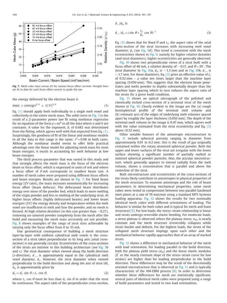
The third process parameter that was varied in this study andthat strongly affects the mesh mass is the focus of the electronbeam or focus offset, which is expressed in units of mA and wherea focus offset of 0 mA corresponds to smallest beam size. Anumber of mesh cubes were prepared using different focus offsetsand beam energies. Results are shown in Fig. 7. For fixed beamenergy (I/V ratio), the mass increases monotonically for increasingfocus offset (beam defocus). The defocussed beam distributesenergy over more of the powder bed, which leads to more meltingof the virgin powder and less re-melting of the underlying strut. Athigher focus offsets (highly defocussed beams) and lower beamenergies (I/V) the energy density and temperature within the meltvoxel are insufficient to melt and fuse the powder, and no mesh isformed. At high relative densities (in this case greater than �0.27),removing un-sintered powder completely from the mesh after thebuild and measuring the mesh mass accurately are not possible.Fig. 8 shows examples of the range of strut sizes achievable byvarying only the focus offset from 0 to 35 mA.
One geometrical consequence of building a mesh structurelayer-by-layer with uniform cylindrical melt voxels is the cross-section of a strut taken perpendicular to its long axis (axial cross-section) is not generally circular. Eccentricities of the cross-sectionsof the struts are intrinsic to this building architecture (see Fig. 5band c). The strut diameter when viewed along the build direction(z-direction), d? , is approximately equal to the cylindrical meltvoxel diameter, dv. However, the strut diameter when viewedperpendicular to the build direction and along the axis of strut tilt,d∥, is approximately given by
d∥ ¼ dv sin θþtv cos θ; ð2Þwhere tv cos θmust be less than dv sin θ in order that the strutbe continuous. The aspect ratio of the perpendicular cross-section,
d?/d∥, is
d? =d∥ ¼ ð sin θþ tvdv
cos θÞ�1 ð3Þ
Eq. (3) shows that for fixed θ and tv, the aspect ratio of the axialcross-section of the strut increases with increasing melt voxeldiameter, dv (see Fig. 5d). This trend is consistent with the mesheccentricities shown in Fig. 9, namely for higher relative densities(and strut diameters), higher eccentricities are generally observed.
Fig. 10 shows two perpendicular views of a strut built with afocus offset of 40 mA, a relative density of �0.17, and θ¼301. Thestrut diameter in Fig. 10a, d∥, is �1.3 mm and in Fig. 10b, d? , is�1.7 mm. For these diameters, Eq. (3) gives an effective value of tvof 0.52 mm – a value ten times larger than the machine layerspacing (0.050 mm). This suggests that the electron beam pene-trates and melts powder to depths substantially deeper than themachine layer spacing which in turn reduces the aspect ratio ofthe struts for a given build condition.
Fig. 11 shows an optical micrograph of the polished andchemically etched cross-section of a terminal strut of the meshshown in Fig. 10. Clearly evident in the image are the (a) roughhemispherical profile of the terminal melt volume and(b) remnant arcs of the edges of underlying melt volumes spacedapart by roughly the layer thickness (0.050 mm). The depth of theterminal melt volume in the image is 0.47 mm, which agrees wellwith the value estimated from the strut eccentricity and Eq. (3)above (0.52 mm).
Other notable features of the anisotropic microstructure inFig. 11 include spherical porosity ranging in diameter fromapproximately 0.01 to 0.2 mm; this is the result of gas originallycontained within the rotary atomized spherical powder. Both theupper and lower surfaces of the strut are irregular with the lowersurface showing a significant number of partially melted orsintered spherical powder particles. Also, the acicular microstruc-ture, which generally appears to extend radially from the meltvolume, shows a concentration that is parallel and above thecenterline of the strut.
Both microstructure and eccentricities of the cross-sections ofthe struts likely contribute to anisotropies in physical properties ofthe mesh structure. To examine anisotropy and the role of beamparameters in determining mechanical properties, some meshcubes were tested in compression between two parallel hardenedsteel plates at a rate of 76 mm/min using a standard MTS Systemsloading apparatus. Fig. 12 shows the results for two nominallyidentical mesh cubes with different orientations of loading. Thebehavior is similar for both cubes and is typical for mesh and foamstructures [5]. For low loads, the stress–strain relationship is linearand struts undergo reversible elastic bending. For moderate loads,a stress plateau is observed where the plateau stress, σpl, is nearlyconstant and the mesh structure irreversibly collapses whilestruts buckle and deform. For the highest loads, the struts of thecollapsed mesh structure impinge upon each other and themechanical behavior rapidly approaches that of an array of stackedstruts.
Fig. 12 shows a difference in mechanical behavior of the meshwith load orientation. For loading parallel to the build direction,both the plateau yield stress (σpl) and the linear elastic modulus(E* or the nearly constant slope of the stress–strain curve for lowstrains) are higher than for loading perpendicular to the builddirection. These differences may be the result of the directionallyoriented microstructure that is observed in Fig. 11 and is typicallycharacteristic of the AM-EBM process [6]. In order to determinewhether these differences for mesh are statistically significant,several pairs of identical mesh cubes were prepared using a rangeof build parameters and tested in two load orientations.
Fig. 7. Mesh cube mass versus I/V for various focus offset currents. Straight linesare fit to data for each focus offset current to guide the eye.
F.A. List et al. / Materials Science & Engineering A 615 (2014) 191–197194
For load along the build direction, Fig. 13 shows some typicalresults for mesh cubes prepared using zero focus offset anddifferent beam currents and beam speeds. By varying only thebeam current and beam speed, large variations in both σpl and E*
are clearly achievable.Fig. 14 shows a compilation of the relative elastic moduli (E*/E0)
and the relative plateau yield stresses (σpl/σ0) versus the relativedensity (ρ*/ρ0) for sixteen mesh cubes tested in compressionperpendicular and parallel to the build direction. Here E0 and σ0are the elastic or Young's modulus (�210 GPa) and yield strength(�1.35 GPa) for bulk Inconel 625 at room temperature. The datashow that the values of both the relative elastic modulus and the
relative yield stress tend to be higher for loads applied parallel to thebuild direction than perpendicular to the build direction. Interest-ingly for lower relative densities (which correspond to lower meltvoxel diameters, lower dv/tv, and lower strut aspect ratios), thedifferences in values for parallel and perpendicular loads are greater.This higher anisotropy of mechanical behavior is contrary to thatexpected from Eq. (3) for struts with a lower aspect ratio of cross-section. The cause of this behavior appears not to be simply struteccentricity but is likely related to microstructural differences suchas (a) the degree of strut melting and the distribution of strutporosity observed in Fig. 9 or (b) the volume fraction of the acicularphase (Fig. 11). Further microstructural analysis is required to
Fig. 8. Four struts viewed parallel to the build direction for different focus offset currents; (a) 0 mA, (b) 15 mA, (c) 25 mA, and (d) 35 mA. The I/V is equal to �0.025 mA s/mmfor all struts.
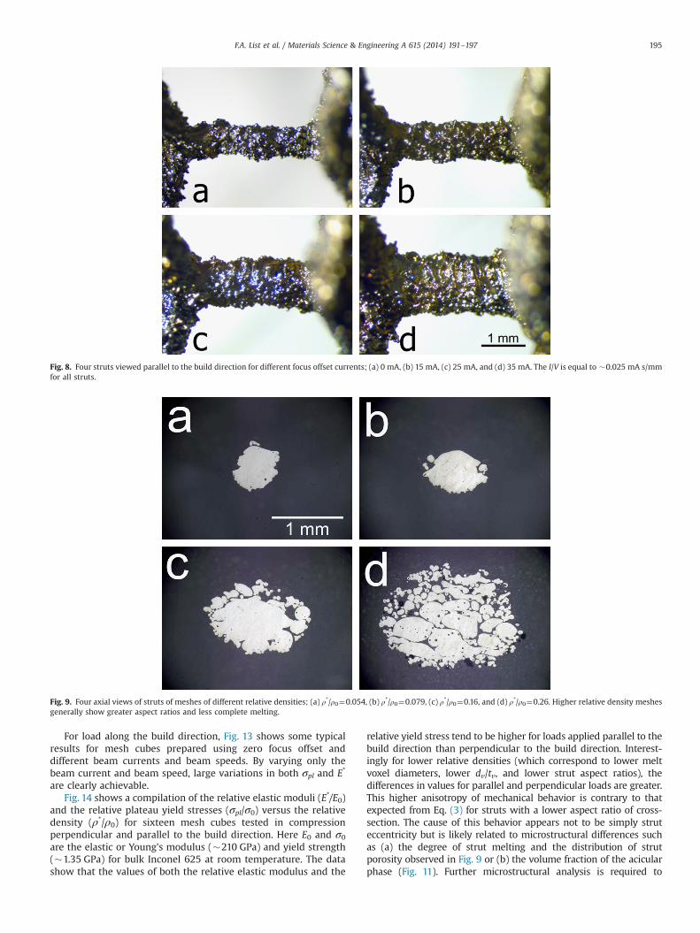
Fig. 9. Four axial views of struts of meshes of different relative densities; (a) ρ*/ρ0¼0.054, (b) ρ*/ρ0¼0.079, (c) ρ*/ρ0¼0.16, and (d) ρ*/ρ0¼0.26. Higher relative density meshesgenerally show greater aspect ratios and less complete melting.
F.A. List et al. / Materials Science & Engineering A 615 (2014) 191–197 195

understand the cause of trends in mechanical anisotropy withrelative density (i.e., strut dimensions) shown in Fig. 14.
Straight lines have been fit to the data in Fig. 14 and haveaverage slopes of 1.9 for both the elastic modulus and yield stress.These values are within a reasonable range of those expected foropen-cell and foam structures (1.5 for yield stress and 2.0 forelastic modulus) [5,7] and are consistent with those reported byothers for Inconel 625 as well as other alloys and pure metals[5,6,8].
Fig. 14 shows that for an Inconel 625 mesh cube both itsmodulus and yield strength can be systematically varied by greaterthan a factor of ten by adjusting only electron beam parameters.This suggests that with proper control software, a single meshstructure can be fabricated layer-by-layer with AM-EBM such thatits physical properties can be specified on a scale approaching themachine layer spacing. This capability, to fabricate fine-scalefunctionally graded structures, is of immediate interest withinthe additive manufacturing community [1,4,9].
Fig. 10. Two views of the same strut; (a) perpendicular to the build direction and along the axis of strut tilt and (b) parallel to the build direction. Here the focus offset is40 mA, and I/V is �0.025 mA s/mm.
Fig. 11. Optical micrograph of the polished and chemically etched cross-section of aterminal strut of the mesh shown in Fig. 10. The inset (upper right) shows theentire strut and its companion.
Fig. 12. Engineering stress versus strain for two mesh cubes with differentorientations of compressive loading. Both cubes were fabricated using identicalbuild conditions and have a relative density of �0.053.
Fig. 13. Engineering compressive stress versus strain for mesh cubes with a rangeof mesh densities. For these data, the load is applied parallel to the build axis (z).
F.A. List et al. / Materials Science & Engineering A 615 (2014) 191–197196

4. Summary
Some relationships between electron beam parameters (beamcurrent, beam speed, and beam focus) and physical properties(mass, diameter, elastic modulus, and yield strength) have been
investigated for Inconel 625 mesh cubes fabricated using AM-EBM.The elastic modulus and yield strength of the mesh cubes have beensystematically varied by approximately a factor of ten by changingthe electron beam parameters. Simple models have been used tounderstand these relationships. Structural anisotropies of the meshassociated with the layered build architecture have been observedand may contribute, along with observed microstructural anisotro-pies, to the anisotropic mechanical properties of the mesh. Knowl-edge of this kind is likely applicable to other metal and alloy AM-EBM systems and is essential to rapidly realize the full potential ofthis burgeoning technology. Future work in this area might include(a) quantifying porosity and microstructure within individual struts,(b) testing tensile properties, (c) exploring effects of annealing onmechanical properties, and (d) comparing mechanical properties tothose based on calculations or simulations.
Acknowledgments
Research sponsored by the U.S. Department of Energy, Office ofEnergy Efficiency and Renewable Energy, Advanced ManufacturingOffice, under Contract DE-AC05-00OR22725 with UT-Battelle, LLC.
References
[1] J. Parthasarathy, B. Starly, S. Raman, A. Christensen, J. Mech. Behav. Biomed.Mater. 3 (2010) 249.
[2] O.L.A. Harrysson, O. Cansizoglu, D.J. Marcellin-Little, D.R. Cormier, H.A. West II,Mater. Sci. Eng. C 28 (2008) 366.
[3] G. Campoli, M.S. Borleffs, S. Amin Yavari, R. Wauthle, H. Weinans, A.A. Zadpoor,Mater. Des. 49 (2013) 957.
[4] L.E. Murr, S.M. Gaytan, F. Medina, H. Lopez, E. Martinez, B.I. Machado, D.H. Hernandez, L. Martinez, M.I. Lopez, R.B. Wicker, J. Bracke, Philos. Trans. R.Soc. A 368 (2010) 1999.
[5] L.J. Gibson, Annu. Rev. Mater. Sci. 30 (2000) 191.[6] L.E. Murr, S.M. Gaytan, D.A. Ramirez, E. Martinez, J. Hernandez, K.N. Amato, P.
W. Shindo, F.R. Medina, R.B. Wicker, J. Mater. Sci. Technol. 28 (1) (2012) 1.[7] L.J. Gibson, M.F. Ashby, Cellular Solids: Structure and Properties, Cambridge
Univ. Press, New York, 1997.[8] P. Heinl, L. Müller, C. Körner, R.F. Singer, F.A. Müller, Acta Biomater. 4 (2008)
1536.[9] P. Heinl, C. Körner, R.F. Singer, Adv. Eng. Mater. 10 (2008) 882.
ρ*/ρ0
0.01 0.1
σ pl /
σ 0
0.001
0.01
Load parallel to zFit parallel n = 1.8Load perpendicular to zFit perpendicular n = 2.0
E*/
E0
0.0001
0.001
Load parallel to zFit parallel n = 1.7Load perpendicular to zFit perpendicular n = 2.1
a
b
Fig. 14. Relative elastic modulus (E*/E0) and relative plateau yield stress (σpl/σ0)versus relative density (ρ*/ρ0) for cubes loaded in compression both parallel andperpendicular to the build axis (z). The lines are fit to the data (see text).
F.A. List et al. / Materials Science & Engineering A 615 (2014) 191–197 197
Related Documents