5/10/2016 Structural modeling of casings in high temperature geothermal wells Gunnar Skúlason Kaldal (PhD student at the UI) ([email protected], [email protected]) Materials Challenges in Geothermal Utilization Seminar on Materials Challenges in Geothermal Utilization Wednesday the 11th of May 2016

Welcome message from author
This document is posted to help you gain knowledge. Please leave a comment to let me know what you think about it! Share it to your friends and learn new things together.
Transcript
5/10/2016
Structural modeling of casings in high temperature geothermal wells
Gunnar Skúlason Kaldal (PhD student at the UI) ([email protected], [email protected])
Materials Challenges in
Geothermal UtilizationSeminar on Materials Challenges in Geothermal Utilization
Wednesday the 11th of May 2016
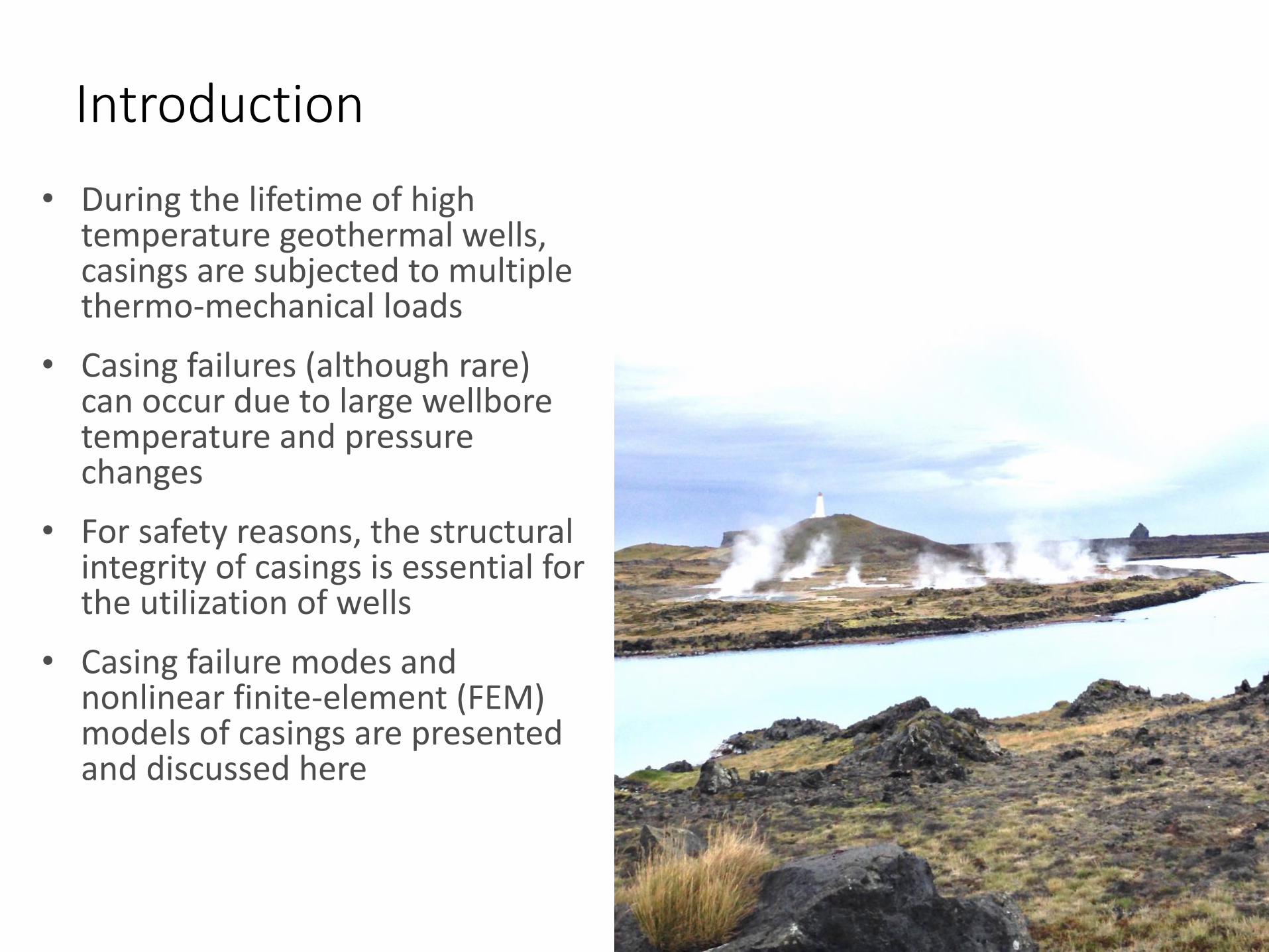
Introduction
• During the lifetime of high temperature geothermal wells, casings are subjected to multiple thermo-mechanical loads
• Casing failures (although rare) can occur due to large wellbore temperature and pressure changes
• For safety reasons, the structural integrity of casings is essential for the utilization of wells
• Casing failure modes and nonlinear finite-element (FEM) models of casings are presented and discussed here

Design challenges
• Casings in HT geothermal wells are constrained by cement and high forces generate plastic (permanent) deformations as the casings warm up.
• Most casing failures that occur in wells are directly related to large temperature changes
• Typical wellhead temperature in high temperature geothermal wells is 200-250°C
• In IDDP-1, the hottest well to date, superheated steam was produced at the wellhead with temperatures of 450°C
• Future aim is to produce from supercritical source where temperatures could reach as high as 550°C
• This provides new challages in casing design
Well design – casing program
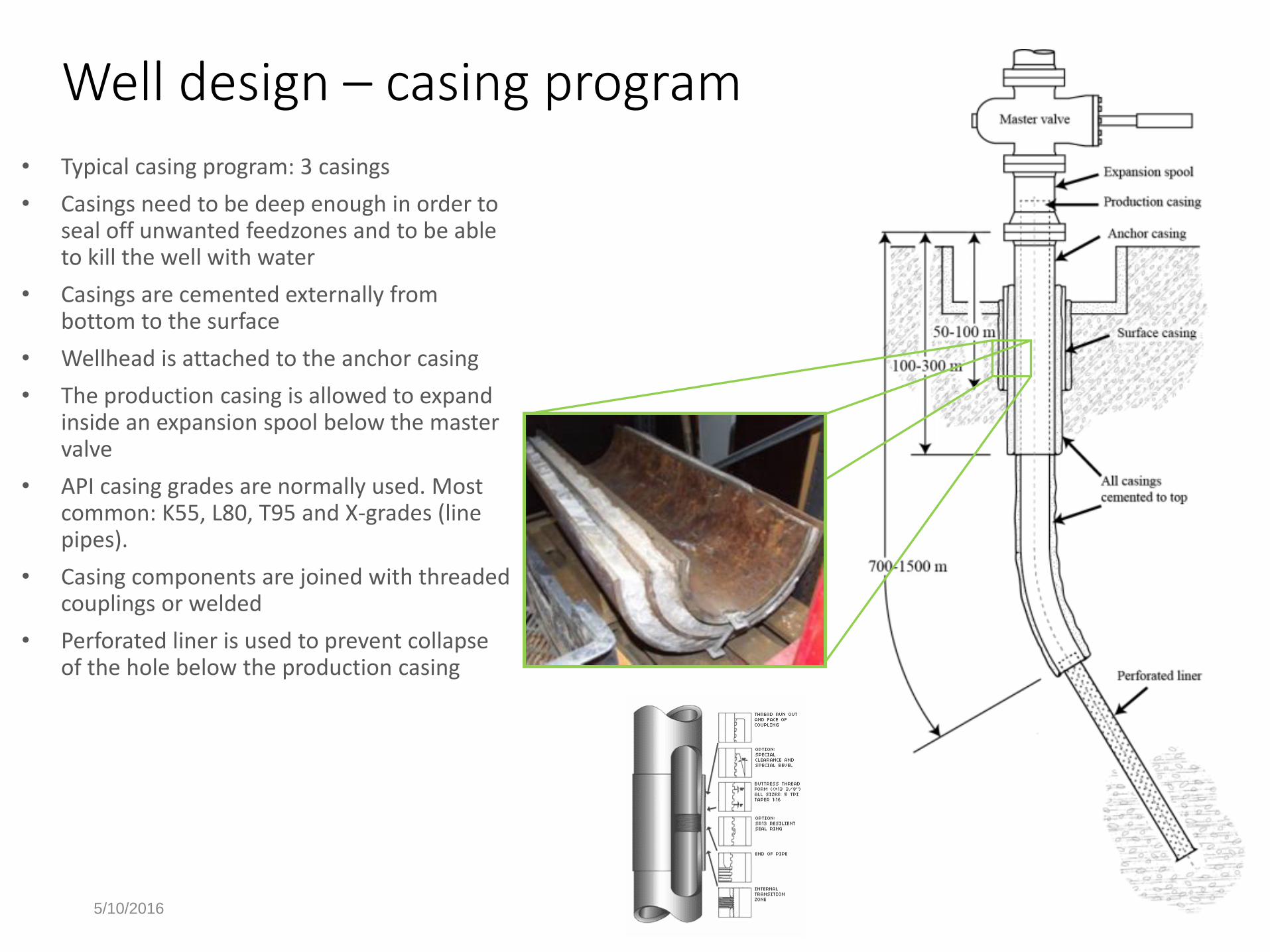
• Typical casing program: 3 casings
• Casings need to be deep enough in order to seal off unwanted feedzones and to be able to kill the well with water
• Casings are cemented externally from bottom to the surface
• Wellhead is attached to the anchor casing
• The production casing is allowed to expand inside an expansion spool below the master valve
• API casing grades are normally used. Most common: K55, L80, T95 and X-grades (line pipes).
• Casing components are joined with threaded couplings or welded
• Perforated liner is used to prevent collapse of the hole below the production casing
5/10/2016

Casing loads• In general casing design is based on axial
tension, burst and collapse
• In geothermal wells, high temperature generates most problems
• Thermal expansion mismatch between casing and concrete layers generates large forces
• Thermal gradient can be high (during discharge)
• Fast temperature changes have greater effect
• Maintainance stops or other shut-in periods where wells cool down generate further risk of failures due to cyclic loading
Tension/
compressionBurst Collapse
5/10/2016
Casing loads and failure modes
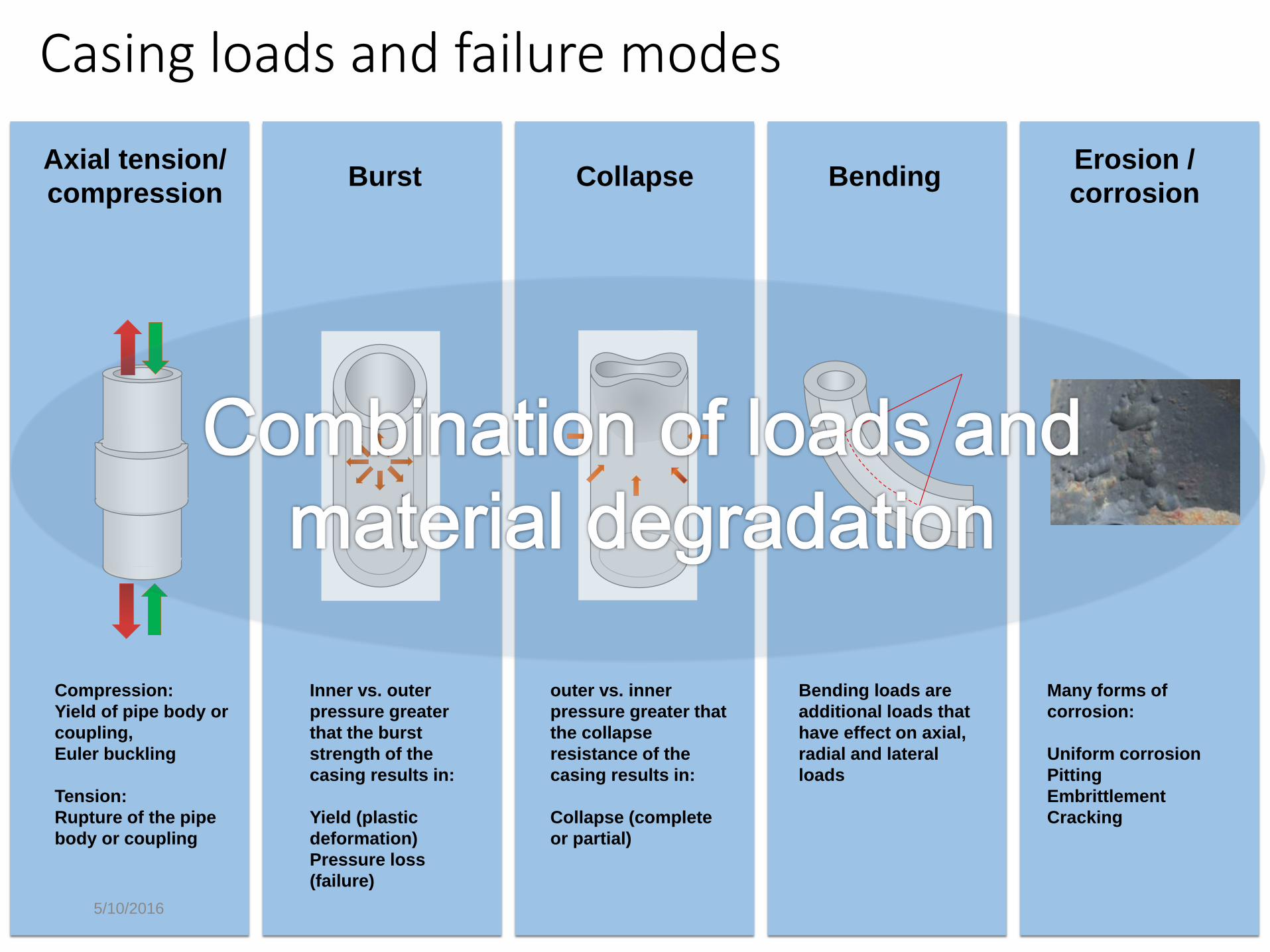
Axial tension/
compression
Compression:
Yield of pipe body or
coupling,
Euler buckling
Tension:
Rupture of the pipe
body or coupling
Burst
Inner vs. outer
pressure greater
that the burst
strength of the
casing results in:
Yield (plastic
deformation)
Pressure loss
(failure)
Collapse
outer vs. inner
pressure greater that
the collapse
resistance of the
casing results in:
Collapse (complete
or partial)
BendingErosion /
corrosion
Many forms of
corrosion:
Uniform corrosion
Pitting
Embrittlement
Cracking
Bending loads are
additional loads that
have effect on axial,
radial and lateral
loads

5/10/2016
Temperature effect
Ref: Behavior of High Strength Structural Steel at Elevated
Temperatures, Chen et.al 2006:
Strength reduction at
elevated temperaturesThermal expansion
Strain →
Str
es
s →
Casing length →
Te
mp
era
ture
ch
an
ge
→
Thermal expansion
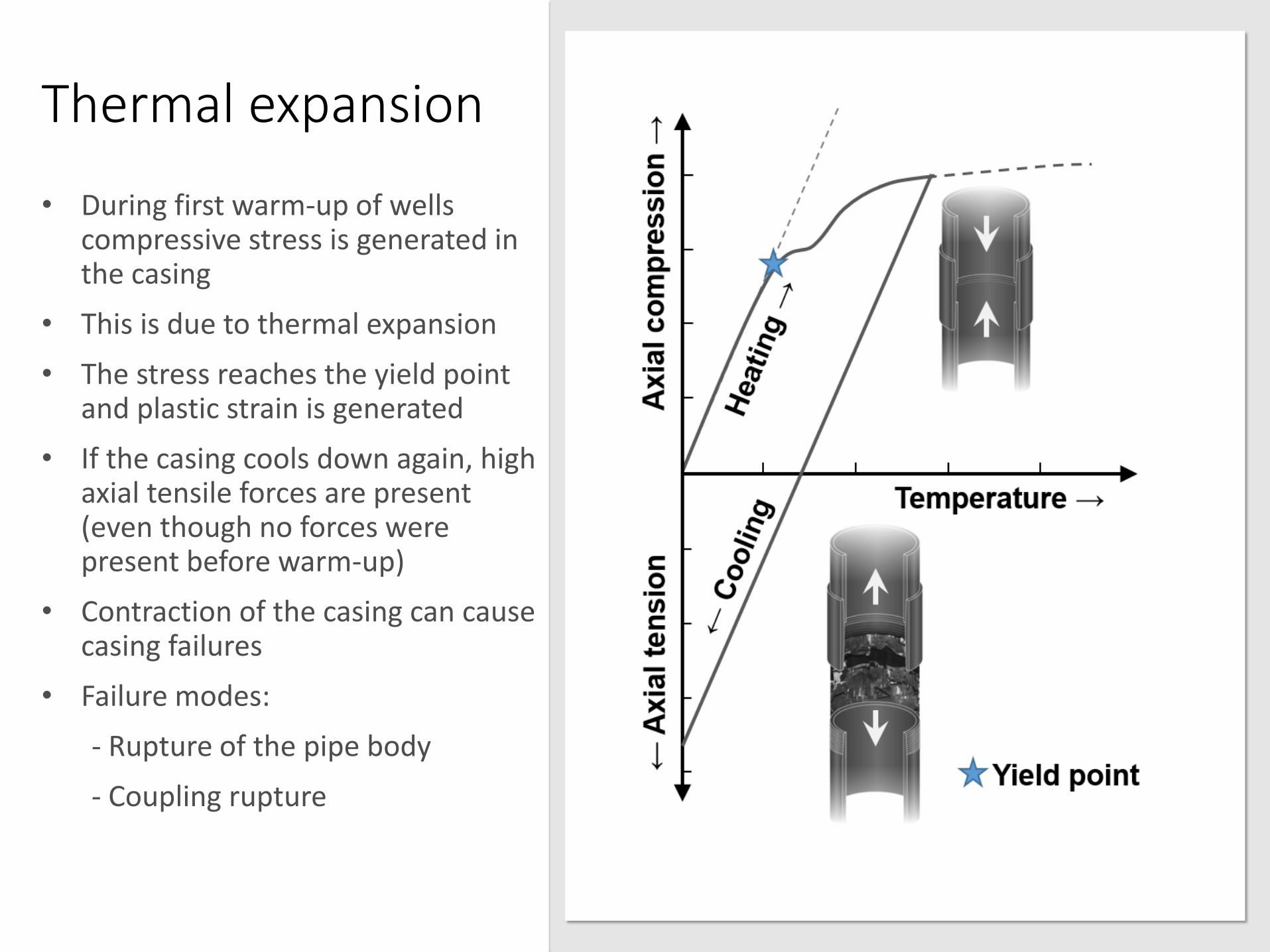
• During first warm-up of wells compressive stress is generated in the casing
• This is due to thermal expansion
• The stress reaches the yield point and plastic strain is generated
• If the casing cools down again, high axial tensile forces are present (even though no forces were present before warm-up)
• Contraction of the casing can cause casing failures
• Failure modes:
- Rupture of the pipe body
- Coupling rupture

5/10/2016
Coupling rupture

Casing collapse
• During installation, complete collapse occurs if external cementing pressure exceeds the collapse resistance of the casing
• Casing collapse can also occur during the operation of wells
• Partial collapse is seen in operating wells
• Caused by expansion of trapped water in annulus between casings or high water content in concrete
• But, absolute reason not clear
• Could also be caused by local pressure fluctuations (vigorous two-phase flow, water hammer, cavitation)
• Probably a combination of defects and loads

FEM modeling
• The nonlinear behavior of materials, displacements and friction between contacting surfaces are solved with numerical methods.
• The Nonlinear Finite Element Method (FEM) is used.
• Thermal and structural models of the cased section of the well.
• The models are used to evaluate the sturctural integrity of the casings when subjected to transient thermo-mechanical loads.
• Applications
Cased section of the well (load history of global structure). Coupling in concrete (details modeled further). 3D section of the well (for collapse analysis).
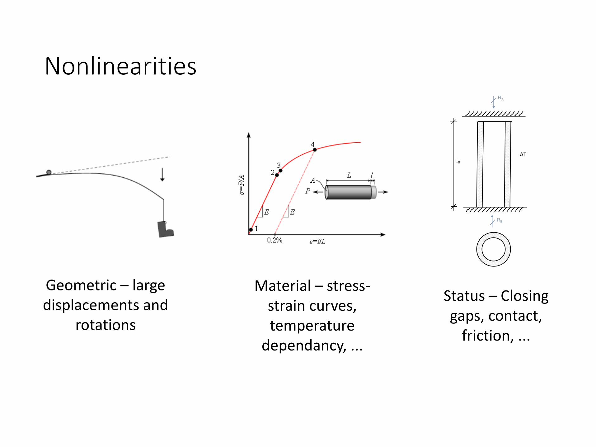
Nonlinearities
Geometric – large displacements and
rotations
Material – stress-strain curves, temperature
dependancy, ...
Status – Closing gaps, contact,
friction, ...
L0
ΔT
RA
RB
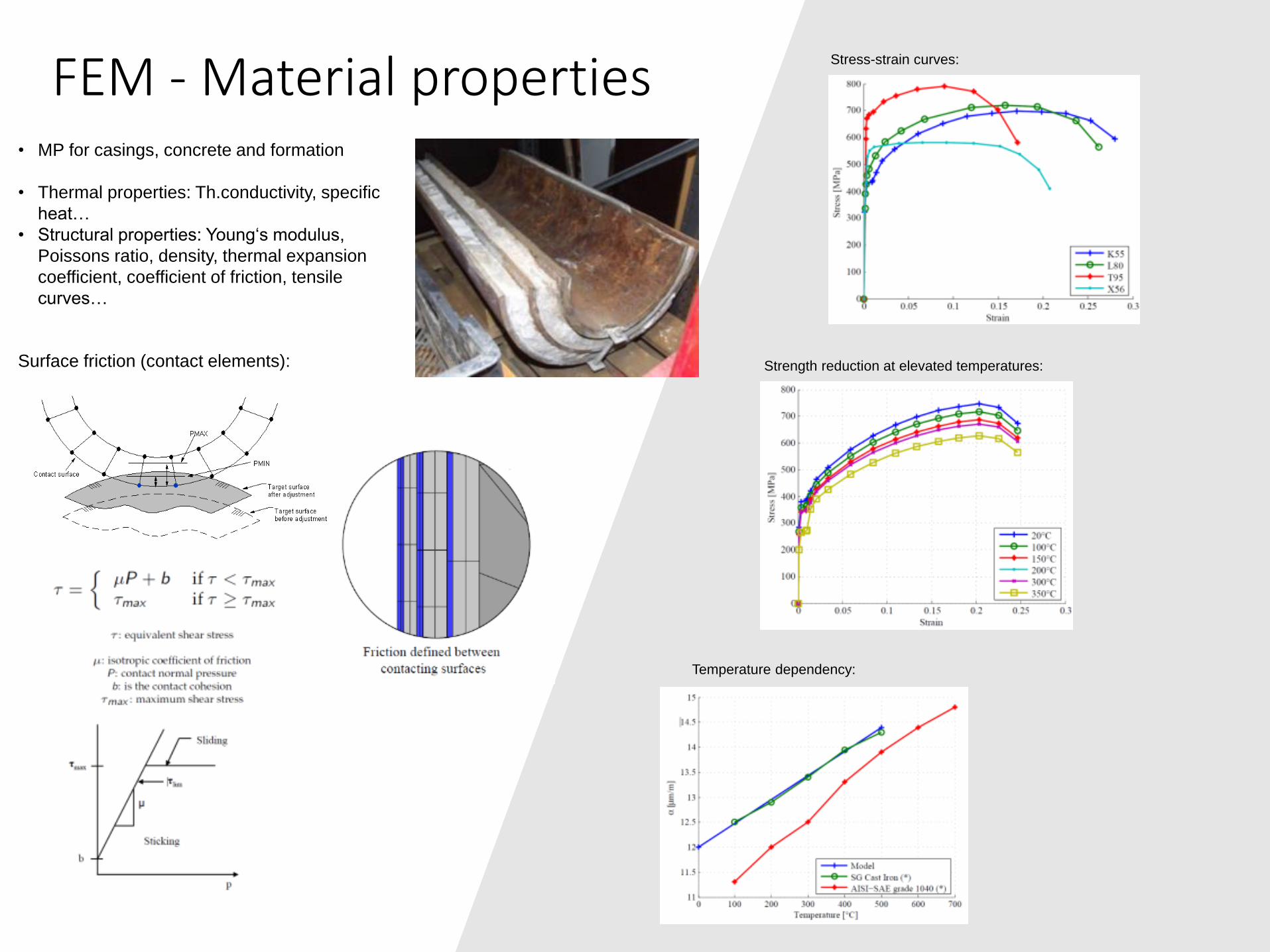
FEM - Material propertiesStress-strain curves:
Strength reduction at elevated temperatures:
Temperature dependency:
Surface friction (contact elements):
• MP for casings, concrete and formation
• Thermal properties: Th.conductivity, specific
heat…
• Structural properties: Young‘s modulus,
Poissons ratio, density, thermal expansion
coefficient, coefficient of friction, tensile
curves…
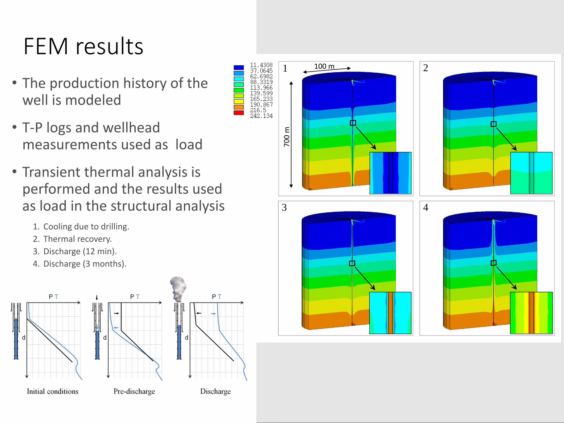
FEM results
• The production history of the well is modeled
• T-P logs and wellhead measurements used as load
• Transient thermal analysis is performed and the results used as load in the structural analysis
1. Cooling due to drilling.
2. Thermal recovery.
3. Discharge (12 min).
4. Discharge (3 months).
1. Cooling due to drilling
2. Warm-up
3. Discharge (12 minutes)
4. Discharge (3 months)
1 2
3 4
70
0 m
100 m
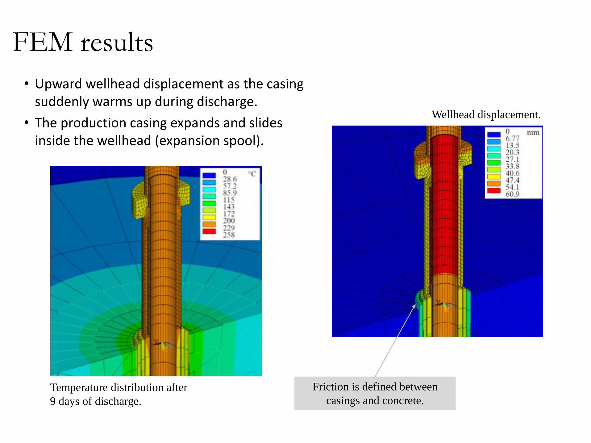
FEM results
• Upward wellhead displacement as the casing suddenly warms up during discharge.
• The production casing expands and slides inside the wellhead (expansion spool).
Wellhead displacement.
Temperature distribution after
9 days of discharge.
Friction is defined between
casings and concrete.
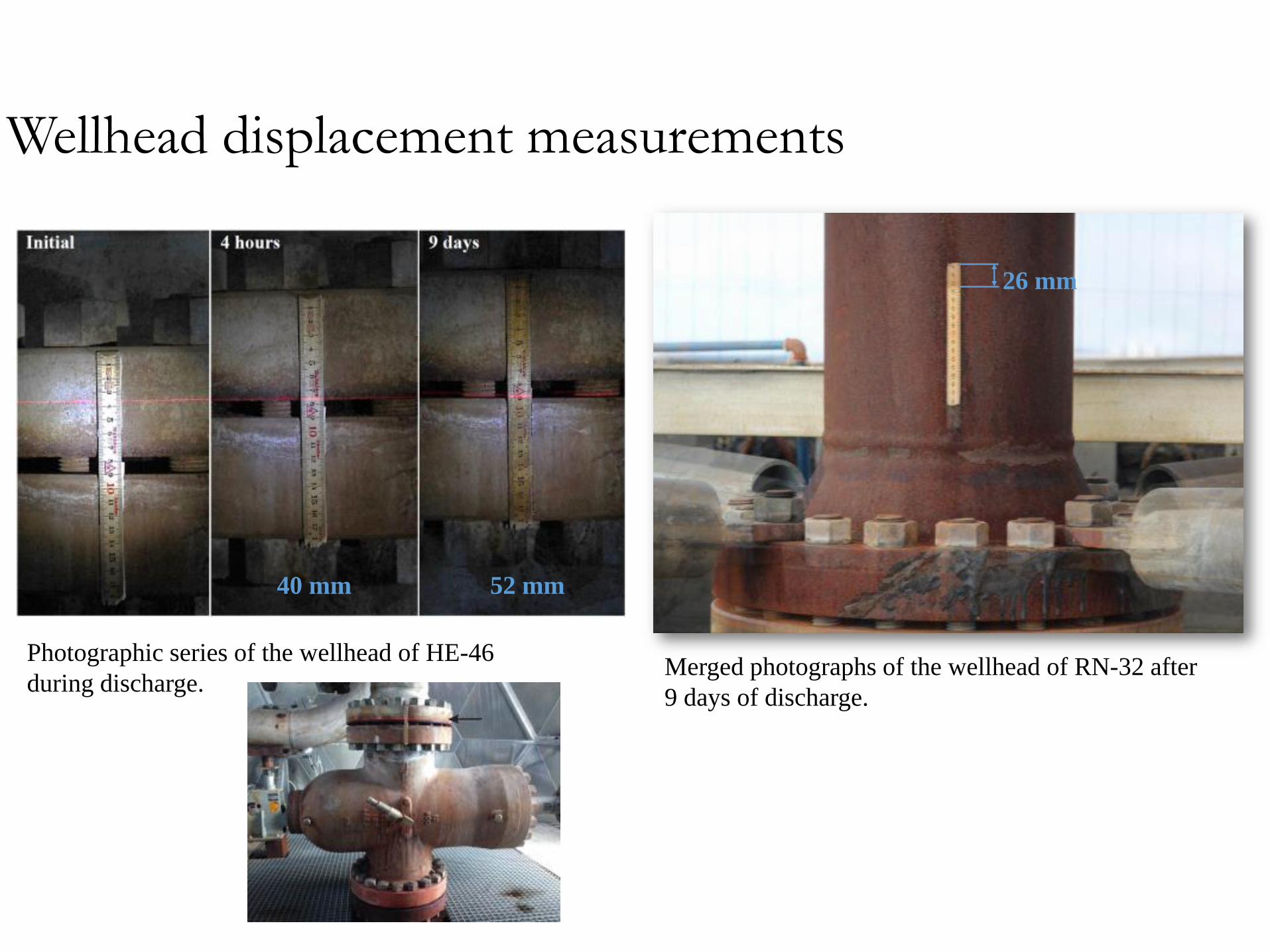
Wellhead displacement measurements
Photographic series of the wellhead of HE-46
during discharge.
52 mm40 mm
Merged photographs of the wellhead of RN-32 after
9 days of discharge.
26 mm
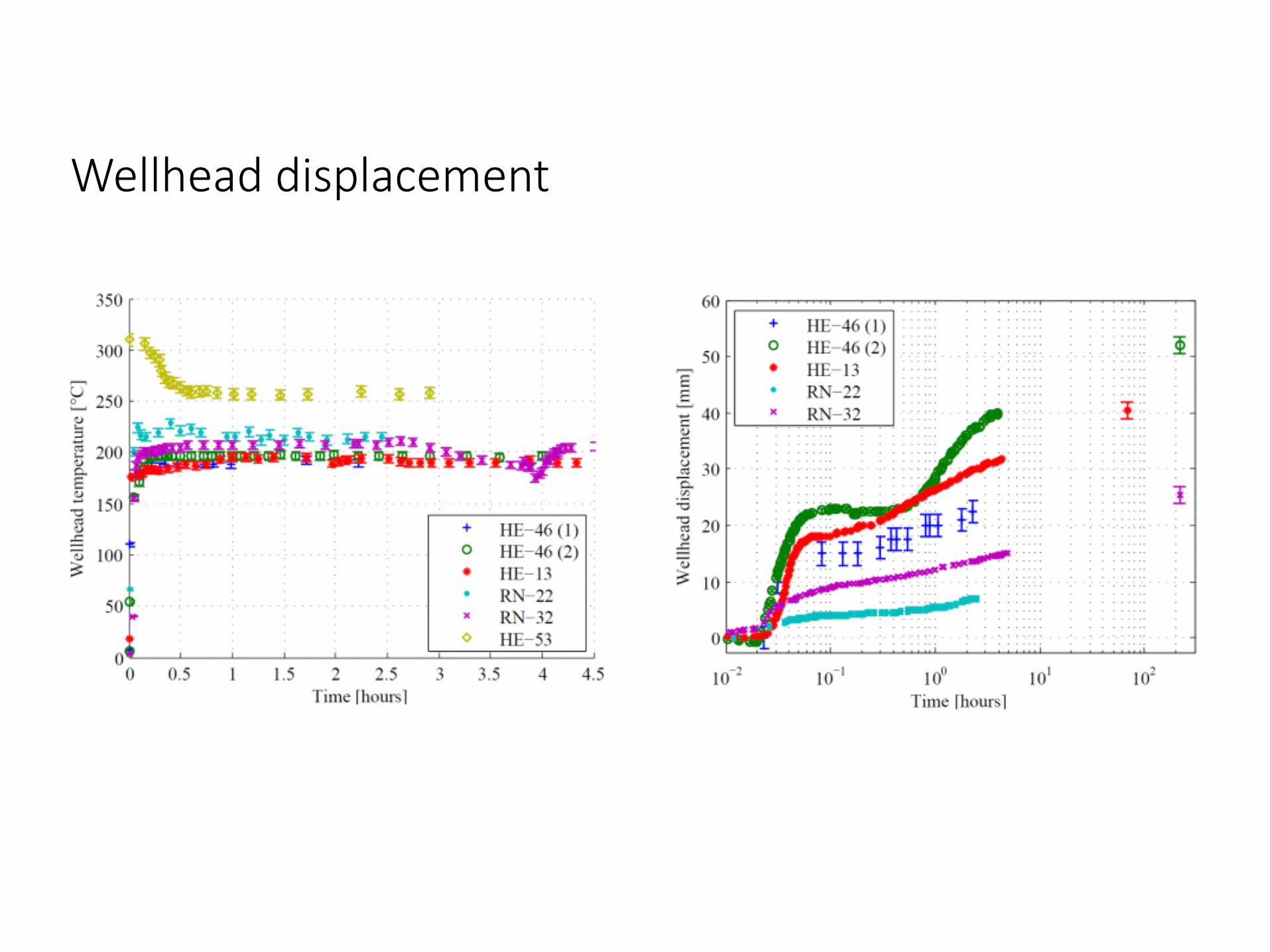
Wellhead displacement
9 days

Wellhead displacement
9 days

• Collapse analysis of the production casing.
• Some instability needs to be introduced.
Collapse analysis
0 5 10 15 20 25 30 35 40 450
10
20
30
40
50
60
70
80
90
100
D/t ratio
K5
5 C
oll
apse
pre
ssu
re [
MP
a]
Yield strength collapse
Plastic collapse
Transition collapse
Elastic collapse
9 5/8 (47.0 lb/ft)
13 3/8 (68.0 lb/ft)
Eigenvalue buckling analysis (theoretical collapse strength).
Casing: OD = 13 3/8 in, t = 12.2 mmAPI collapse resistance: 13.4 MPa
Eigenvalue buckling analysis (theoretical collapse strength). Nonlinear buckling analysis (includes nonlinearities). Effect of initial geometry; mode shape perturbation, ovality and external geometric defect. Collapse shape with and without external concrete support.
1
5
2
6
3
7
4
8
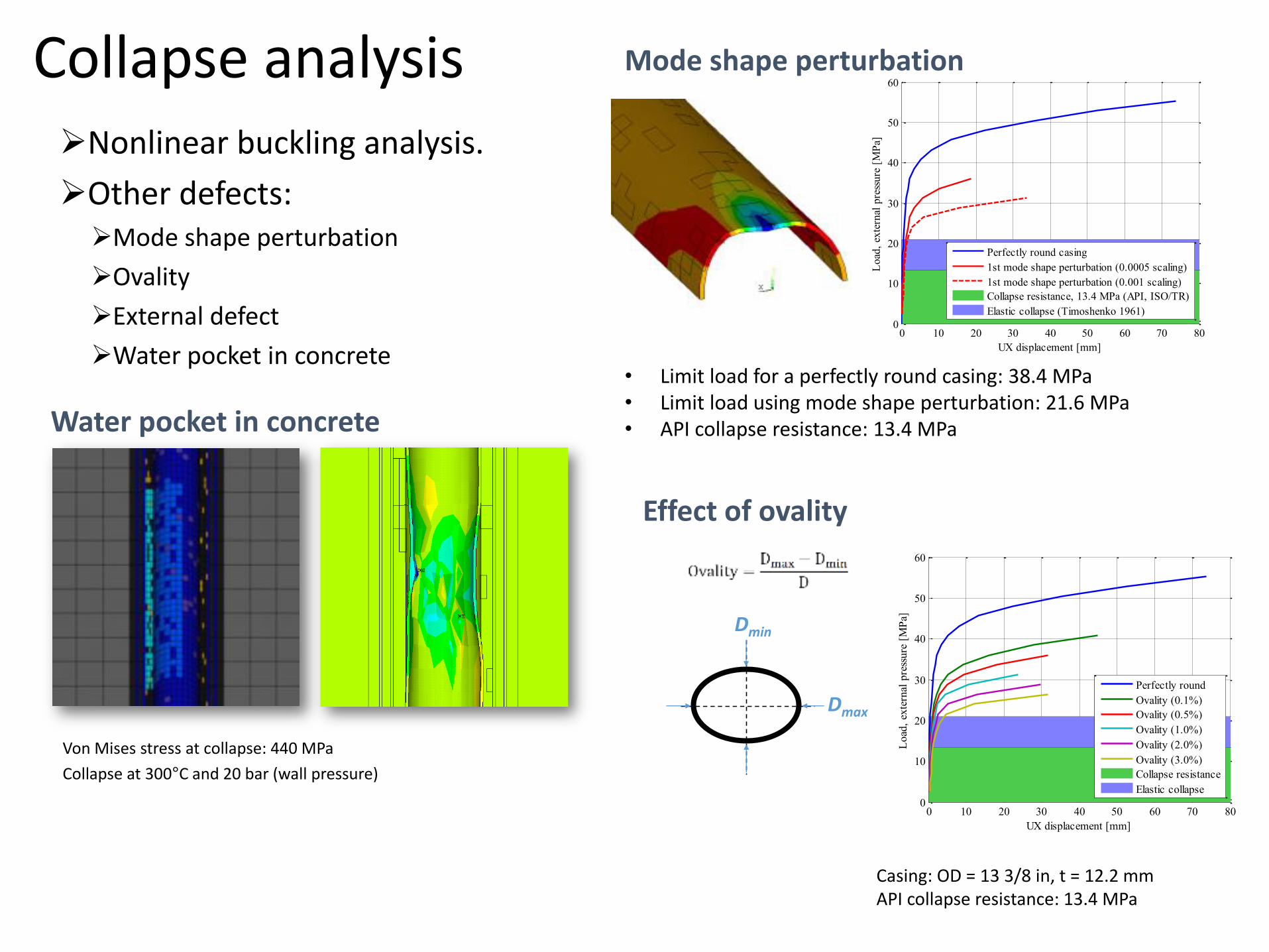
Nonlinear buckling analysis.
Other defects:Mode shape perturbation
Ovality
External defect
Water pocket in concrete
Casing: OD = 13 3/8 in, t = 12.2 mmAPI collapse resistance: 13.4 MPa
• Limit load for a perfectly round casing: 38.4 MPa• Limit load using mode shape perturbation: 21.6 MPa • API collapse resistance: 13.4 MPa
0 10 20 30 40 50 60 70 800
10
20
30
40
50
60
Lo
ad,
exte
rnal
pre
ssu
re [
MP
a]
UX displacement [mm]
Perfectly round casing
1st mode shape perturbation (0.0005 scaling)
1st mode shape perturbation (0.001 scaling)
Collapse resistance, 13.4 MPa (API, ISO/TR)
Elastic collapse (Timoshenko 1961)
Mode shape perturbation
Dmax
Dmin
Effect of ovality
0 10 20 30 40 50 60 70 800
10
20
30
40
50
60
Load
, ex
tern
al p
ress
ure
[M
Pa]
UX displacement [mm]
Perfectly round
Ovality (0.1%)
Ovality (0.5%)
Ovality (1.0%)
Ovality (2.0%)
Ovality (3.0%)
Collapse resistance
Elastic collapse
Von Mises stress at collapse: 440 MPa
Collapse at 300°C and 20 bar (wall pressure)
Water pocket in concrete
Collapse analysis

Nonlinear buckling analysis
0 50 100 150 200 250 3000
10
20
30
40
50
60
Displacement [mm]
Load
, ex
tern
al p
ress
ure
[M
Pa]
Concrete support (linear MP)
Without concrete support (linear MP)
Concrete support (non-linear MP)
Without concrete support (non-linear MP)
Collapse resistance, 13.4 MPa (API, ISO/TR)
Elastic collapse (Timoshenko 1961)
Casing: OD = 13 3/8 in, t = 12.2 mmAPI collapse resistance: 13.4 MPa
Effect of external defect and concrete support
Collapse analysis
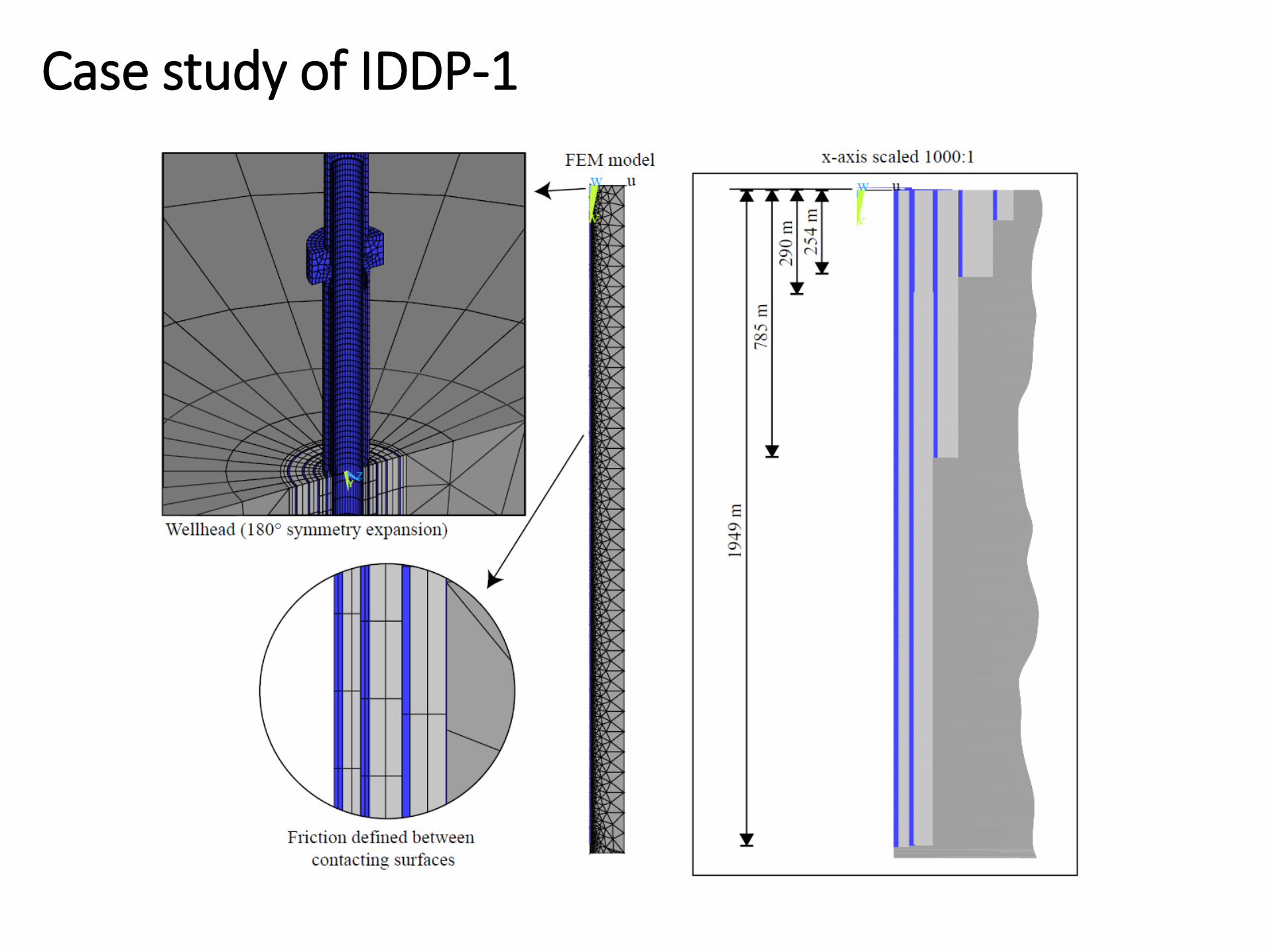
“As-built” drawing of IDDP-1 (Pálson et.al 2013, Drilling of the well IDDP-1)
Case study of IDDP-1

Load history of IDDP-1
Wellbore load in the model:
Load history:Ingason et.al, Geothermics 2013:

Transient thermal distribution
Thermal recovery from
drillingDischarge – 2 months Discharge – 11 months Quenching – 8 hours
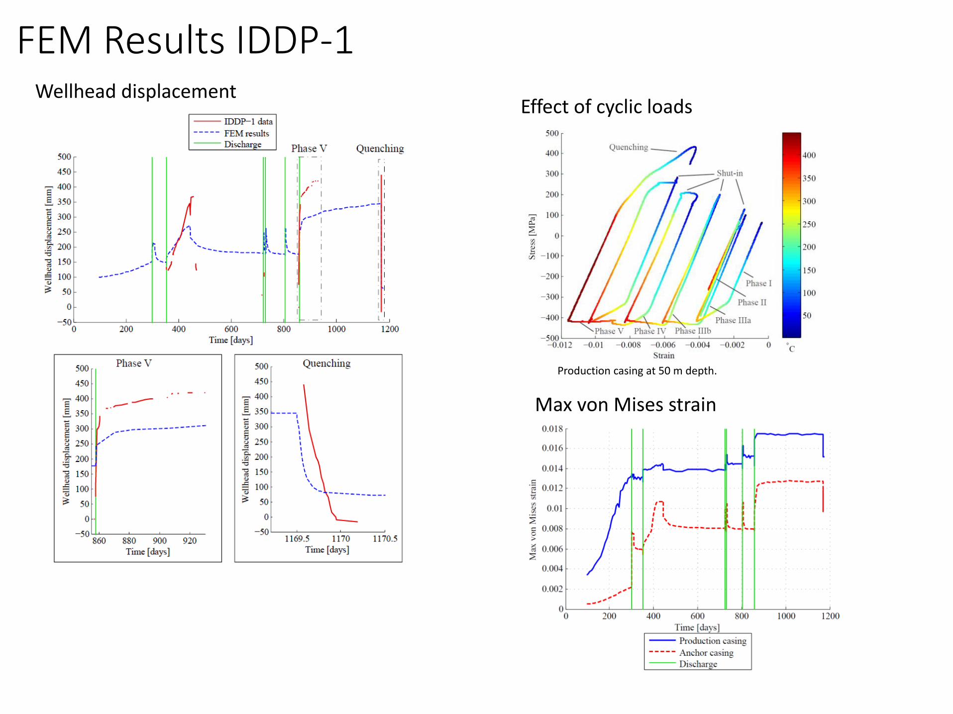
FEM Results IDDP-1Wellhead displacement
Max von Mises strain
Effect of cyclic loads
Production casing at 50 m depth.
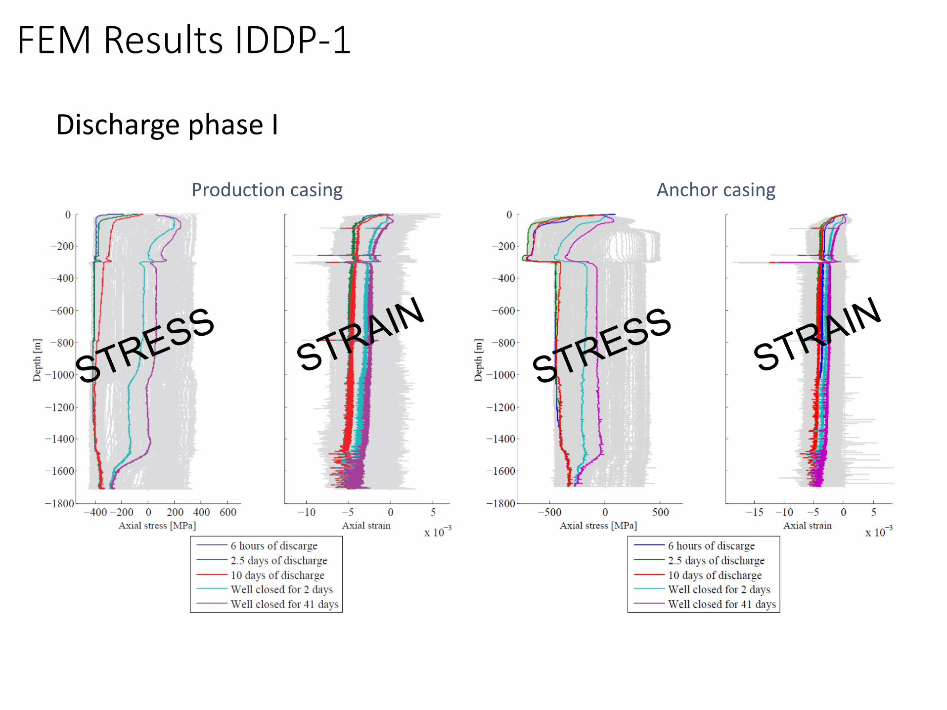
Discharge phase I
Production casing Anchor casing
FEM Results IDDP-1
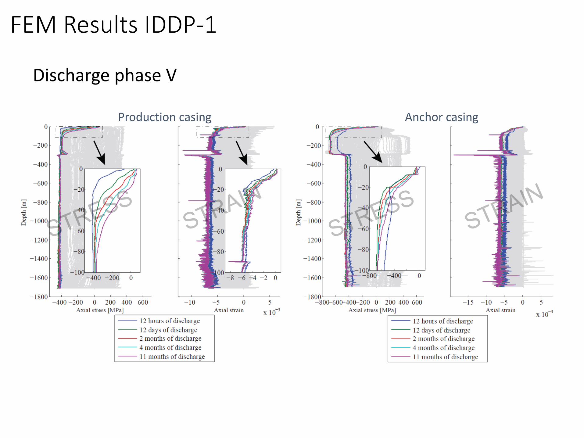
Discharge phase V
Production casing Anchor casing
FEM Results IDDP-1

Quenching
FEM Results IDDP-1
Production casing Anchor casing
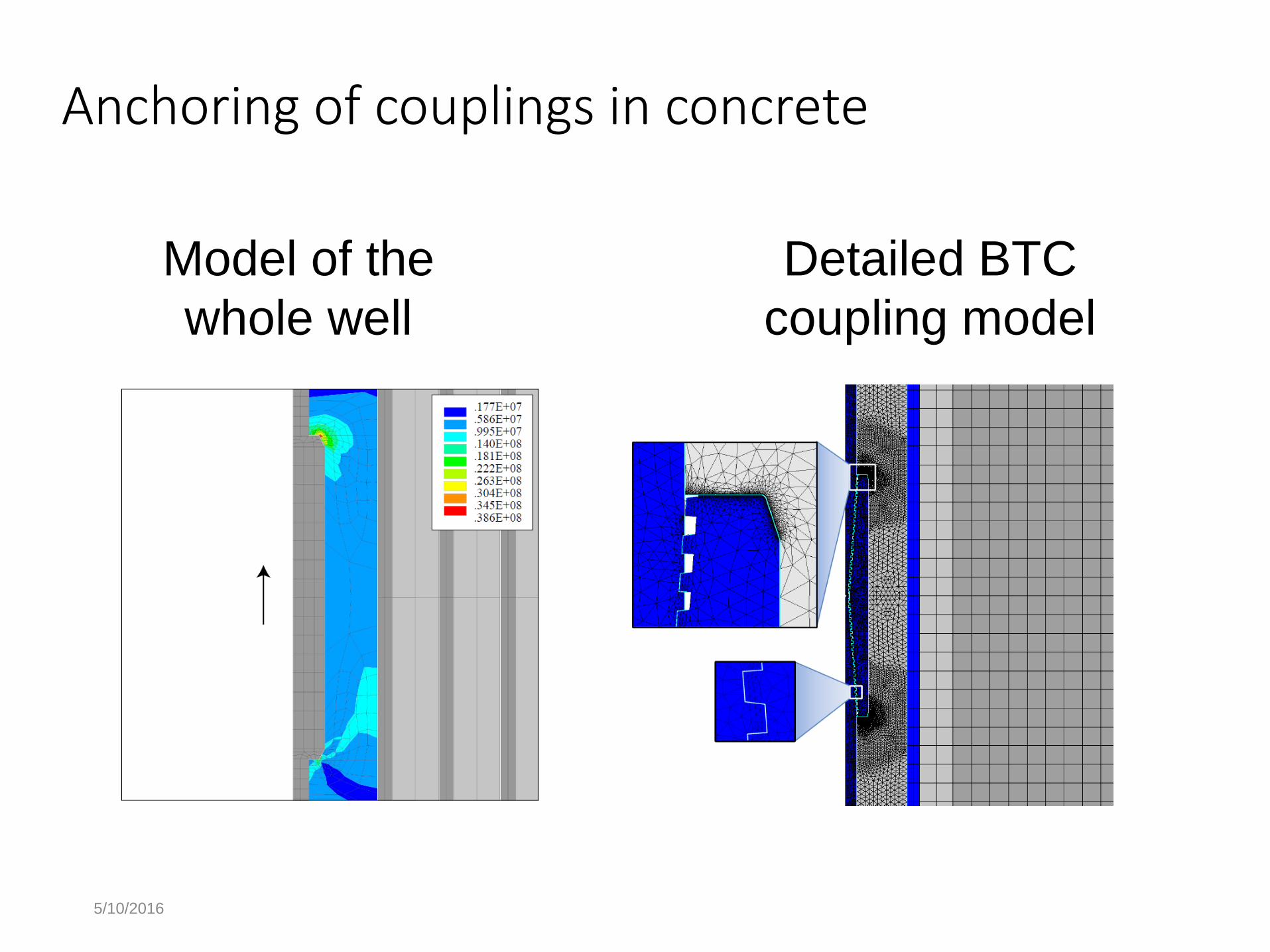
Anchoring of couplings in concrete
5/10/2016
Model of the
whole well
Detailed BTC
coupling model

Anchoring of couplings in concrete
5/10/2016
Coupling displacement in concrete
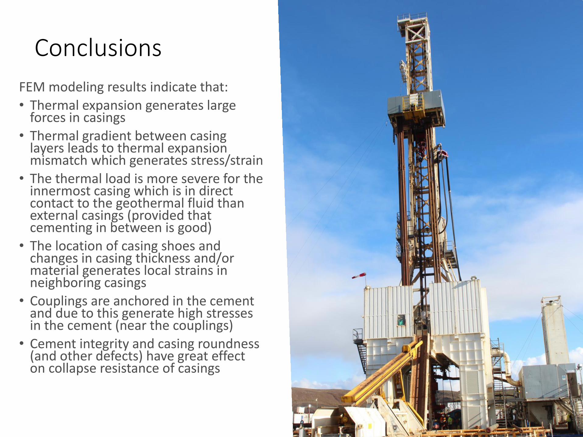
Conclusions
FEM modeling results indicate that:
• Thermal expansion generates large forces in casings
• Thermal gradient between casing layers leads to thermal expansion mismatch which generates stress/strain
• The thermal load is more severe for the innermost casing which is in direct contact to the geothermal fluid than external casings (provided that cementing in between is good)
• The location of casing shoes and changes in casing thickness and/or material generates local strains in neighboring casings
• Couplings are anchored in the cement and due to this generate high stresses in the cement (near the couplings)
• Cement integrity and casing roundness (and other defects) have great effect on collapse resistance of casings
5/10/2016
Acknowledgements
• The University of Iceland research fund
• The Technology Development Fund at RANNIS –The Icelandic Centre for Research
• GEORG – Geothermal Research Group
• Landsvirkjun Energy Research Fund
• Reykjavik Energy, HS Orka, Landsvirkjun, Iceland Drilling, Iceland Geosurvey (ÍSOR), Mannvit and the Innovation Center Iceland.
5/10/2016
Thank you
Related Documents