Harnessing multi-layered soil to design seismic metamaterials with ultralow frequency band gaps Yanyu Chen a , Feng Qian b , Fabrizio Scarpa c , Lei Zuo b, ⁎, Xiaoying Zhuang d,e, ⁎⁎ a Department of Mechanical Engineering, University of Louisville, Louisville, KY 40292, USA b Department of Mechanical Engineering, Virginia Tech, Blacksburg, VA 24061, USA c Bristol Composites Institute (ACCIS) and Dynamics and Control Research Group (DCRG), University of Bristol, BS8 1TR Bristol, UK d Department of Geotechnical Engineering, College of Civil Engineering, Tongji University, Shanghai 200092, PR China e State Key Laboratory for Disaster Reduction in Civil Engineering, Tongji University, Shanghai 200092, PR China HIGHLIGHTS • Lab scale experiments were conducted to understand elastic wave propagation in seismic metamaterials. • Finite element models for wave propa- gation analysis were validated against the experiments. • Multi-layered seismic metamaterials can attenuate surface waves by confin- ing wave energy. • Broadband cut-off band gaps up to 7.2 Hz were predicted in the multilay- ered seismic metamaterials. GRAPHICAL ABSTRACT abstract article info Article history: Received 5 March 2019 Received in revised form 9 April 2019 Accepted 21 April 2019 Available online 23 April 2019 Phononic metamaterials are capable of manipulating mechanical wave propagation in applications ranging from nanoscale heat transfer to noise and vibration mitigation. The design of phononic metamaterials to control low- frequency vibrations, such as those induced by ground transportation and low-amplitude seismic waves, how- ever, remains a challenge. Here we propose a new design methodology to generate seismic metamaterials that can attenuate surface waves below 10 Hz. Our design concept evolves around the engineering of the multi- layered soil, the use of conventional construction materials, and operational construction constraints. The pro- posed seismic metamaterials are constructed by periodically varying concrete piles in the host multi-layered soil. We first validate the design concept and the numerical models by performing a lab-scale experiment on the low-amplitude surface wave propagation in a finite-size seismic metamaterial. To the best of the Authors' knowledge, this is one of the few attempts made to date to experimentally understand the vibration mitigation capability of seismic metamaterials. We then numerically demonstrate that the multi-layered seismic metama- terials can attenuate surface waves over a wide frequency range, with the incident wave energy being confined within the softest layer of the shallow layered seismic metamaterials. In addition to the localized wave energy distribution, deep layered seismic metamaterials exhibit broadband cut-off band gaps up to 7.2 Hz due to the strongly imposed constraint between piles and surrounding soil. Furthermore, these cut-off band gaps strongly depend on the constraint between the piles and the bottom layer of the soil and hence can be tuned by tailoring Keywords: Seismic metamaterial Vibration Multilayered soil Wave propagation Phononic Band gaps Materials and Design 175 (2019) 107813 ⁎ Corresponding author. ⁎⁎ Correspondence to: X. Zhuang, Department of Geotechnical Engineering, College of Civil Engineering, Tongji University, Shanghai 200092, PR China. E-mail addresses: [email protected] (L. Zuo), [email protected] (X. Zhuang). https://doi.org/10.1016/j.matdes.2019.107813 0264-1275/© 2019 The Authors. Published by Elsevier Ltd. This is an open access article under the CC BY-NC-ND license (http://creativecommons.org/licenses/by-nc-nd/4.0/). Contents lists available at ScienceDirect Materials and Design journal homepage: www.elsevier.com/locate/matdes

Welcome message from author
This document is posted to help you gain knowledge. Please leave a comment to let me know what you think about it! Share it to your friends and learn new things together.
Transcript
Materials and Design 175 (2019) 107813
Contents lists available at ScienceDirect
Materials and Design
j ourna l homepage: www.e lsev ie r .com/ locate /matdes
Harnessing multi-layered soil to design seismic metamaterials withultralow frequency band gaps
Yanyu Chen a, Feng Qian b, Fabrizio Scarpa c, Lei Zuo b,⁎, Xiaoying Zhuang d,e,⁎⁎a Department of Mechanical Engineering, University of Louisville, Louisville, KY 40292, USAb Department of Mechanical Engineering, Virginia Tech, Blacksburg, VA 24061, USAc Bristol Composites Institute (ACCIS) and Dynamics and Control Research Group (DCRG), University of Bristol, BS8 1TR Bristol, UKd Department of Geotechnical Engineering, College of Civil Engineering, Tongji University, Shanghai 200092, PR Chinae State Key Laboratory for Disaster Reduction in Civil Engineering, Tongji University, Shanghai 200092, PR China
H I G H L I G H T S G R A P H I C A L A B S T R A C T
• Lab scale experiments were conductedto understand elastic wave propagationin seismic metamaterials.
• Finite element models for wave propa-gation analysis were validated againstthe experiments.
• Multi-layered seismic metamaterialscan attenuate surface waves by confin-ing wave energy.
• Broadband cut-off band gaps up to7.2 Hz were predicted in the multilay-ered seismic metamaterials.
⁎ Corresponding author.⁎⁎ Correspondence to: X. Zhuang, Department of Geotec
E-mail addresses: [email protected] (L. Zuo), xiaoyingzhu
https://doi.org/10.1016/j.matdes.2019.1078130264-1275/© 2019 The Authors. Published by Elsevier Ltd
a b s t r a c t
a r t i c l e i n f oArticle history:Received 5 March 2019Received in revised form 9 April 2019Accepted 21 April 2019Available online 23 April 2019
Phononic metamaterials are capable of manipulating mechanical wave propagation in applications ranging fromnanoscale heat transfer to noise and vibration mitigation. The design of phononic metamaterials to control low-frequency vibrations, such as those induced by ground transportation and low-amplitude seismic waves, how-ever, remains a challenge. Here we propose a new design methodology to generate seismic metamaterials thatcan attenuate surface waves below 10 Hz. Our design concept evolves around the engineering of the multi-layered soil, the use of conventional construction materials, and operational construction constraints. The pro-posed seismic metamaterials are constructed by periodically varying concrete piles in the host multi-layeredsoil. We first validate the design concept and the numerical models by performing a lab-scale experiment onthe low-amplitude surface wave propagation in a finite-size seismic metamaterial. To the best of the Authors'knowledge, this is one of the few attempts made to date to experimentally understand the vibration mitigationcapability of seismic metamaterials. We then numerically demonstrate that the multi-layered seismic metama-terials can attenuate surface waves over a wide frequency range, with the incident wave energy being confinedwithin the softest layer of the shallow layered seismic metamaterials. In addition to the localized wave energydistribution, deep layered seismic metamaterials exhibit broadband cut-off band gaps up to 7.2 Hz due to thestrongly imposed constraint between piles and surrounding soil. Furthermore, these cut-off band gaps stronglydepend on the constraint between the piles and the bottom layer of the soil and hence can be tuned by tailoring
Keywords:Seismic metamaterialVibrationMultilayered soilWave propagationPhononicBand gaps
hnical Engineering, College of Civil Engineering, Tongji University, Shanghai 200092, PR [email protected] (X. Zhuang).
. This is an open access article under the CC BY-NC-ND license (http://creativecommons.org/licenses/by-nc-nd/4.0/).

2 Y. Chen et al. / Materials and Design 175 (2019) 107813
the foundation stiffness. We also evidence the possibility to create constant wave band gaps by introducing hol-low concrete piles with pile volume fraction b10% in the deep layered seismic metamaterials. The findings re-ported here open new avenues to protect engineering structures from low-frequency seismic vibrations.
©2019 The Authors. Published by Elsevier Ltd. This is an open access article under the CC BY-NC-ND license(http://creativecommons.org/licenses/by-nc-nd/4.0/).
1. Introduction
Undesired mechanical vibrations arising from ground transporta-tion, use of machinery in construction sites and low-amplitude earth-quakes not only cause disruptions, but also have adverse health, social,and economic impacts. A rich low-frequency dynamics environment isabundant in metropolitan areas with high-density population andhigh capacity of motorways and railways. As such, serious potentialhealth effects are induced due to the increased noise and vibration.For example, early small-scale laboratory investigation has shown thata combination of noise and vibration induced by heavy road traffic cancause significant sleep disturbances [1]. In addition to these apparentdisturbances, ground vibrations and low amplitude seismicwaves affectthe proper operation of highly sensitive instruments, which are oftenemployed in scientific research laboratories and high-tech industries.Technical and environmental challenges are nowparticularly addressedin the new built environment to tackle noise and groundmotion. Manyvibration mitigation approaches have been proposed to mitigate oreliminate the effects of vibration on infrastructures and facilities.Among those, passive vibration isolation solutions have attracted a sig-nificant amount of interest. For example, open or filled trenches [2–4]and large volume concrete piles [5–9] are often employed as wave bar-riers in engineering practice. Open/filled trenches are designed to inter-rupt the wave propagation path and hence mitigate mechanicalvibrations for shallow structures. Concrete piles have been recentlyexploited as a new vibration mitigation approach for deep structuressince they are immune to the influence of high groundwater level andcan also enhance the ground load capacity. Experimental studies havevalidated the effectiveness of pile barriers to reduce structural vibra-tions subjected to ground vibration [9]. Though these vibration mitiga-tion approaches have been widely adopted in current engineeringpractice, a quantitative understanding of the effectiveness at target fre-quency ranges is still not completely reached yet.
Recent studies have shown that phononic metamaterials, which arerationally designedmultiscale material systems, can manipulate propa-gating mechanical waves, and therefore offer new solutions to effec-tively control noise and vibrations [10–19]. The intrinsic periodic arraynature of phononic metamaterials leads to the modification of phonondispersion relations and the possibility of tailoring group velocities.One of the remarkable features in phonon dispersion relations is the ex-istence of omnidirectional band gaps, i.e. frequency ranges in which thepropagation of phonons is prohibited, irrespective of the direction of theincident waves. Seismic metamaterials have been developed to makeuse of omnidirectional band gap properties, for minimizing undesiredground vibrations and low-amplitude seismicwaves [20–28]. For exam-ple, two-dimensional (2D) periodic composite systems, akin to 2Dphononic crystals, have been designed and been numerically shown tohave the capability to attenuate ground vibrations for civil infrastruc-tures [29–34]. In parallel, a lab-scale experiment has been conductedto test the vibration mitigation ability of a scaled periodic foundation[35]. More recently, a large-scale seismic metamaterial composed of aperiodic array of cylindrical boreholes in soil has been developed to con-trol low amplitude surface waves [36]. In situ experiment has demon-strated that the proposed seismic metamaterial can effectively reflectincoming waves at 50 Hz, and this has also been validated by the nu-merical simulations. The frequency ranges of most ground transporta-tion vibrations and seismic waves are typically below 10 Hz; thisrequires the use of components with large sizes and, therefore, makes
the above periodic structures concepts very difficult to apply. To over-come this limitation, locally resonant seismic metamaterials with low-frequency band gaps have been proposed [22,25,37,38]. Both numericalmodeling and lab-scale experiments have demonstrated that artificiallydesigned resonator geometries can be employed to control low-frequency vibrations. Nonetheless, these resonators typically have com-plex architectures and consist of multiple materials systems. Complex-ity and the assembly of heterogeneous materials could pose asignificant challenge to build an effective seismic metamaterial atlarge scale in a construction site.
Here we propose a methodology to create a new class of seismicmetamaterials to mitigate low-frequency surface waves (b10 Hz) oc-curring in ground transportation-induced low amplitude vibrationsand low-amplitude seismic waves. Our design builds upon the use ofmulti-layered soil with different mechanical properties and takes intoconsideration the availability of conventional construction materialsand the presence of build constraints.We first validate our designmeth-odology by performing a lab-scale experiment on surface wave trans-mission in a homogenous seismic metamaterial. We then performnumerical simulations to understand the effect of soil layering on themitigation of surfacewave transmission.We also describe how the pro-posed design methodology could be used to create cost-effective seis-mic metamaterials. This work stands out as a practical designcombining the usage of conventional construction materials with thebroadband and ultralow frequency vibration mitigation capability.
2. Materials and methods
2.1. Multilayered seismic metamaterial design
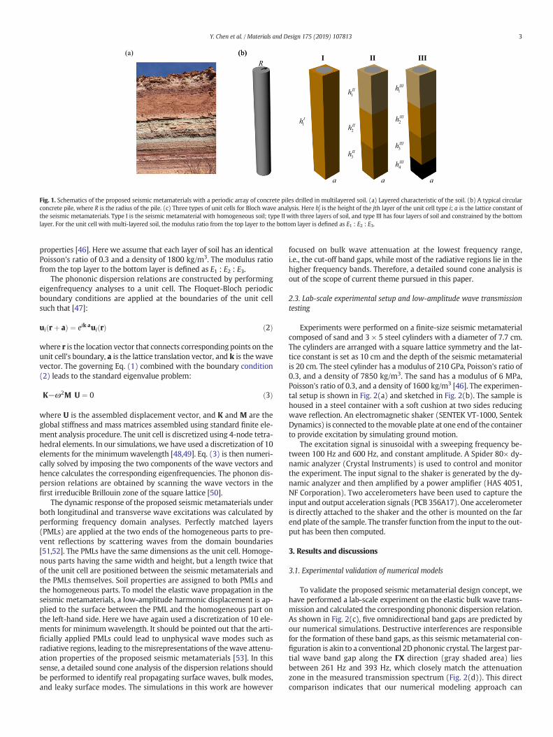
Our design is inspired by the observation that multiple layers withdifferent mechanical properties exist in the soils [39–41] (Fig. 1(a)).We also consider the availability of conventional constructionmaterialsand real construction/building constraints; circular concrete piles aretherefore considered in this work (Fig. 1(b)). By periodically drilling cir-cular concrete piles into the layered soil,we obtain a new type of seismicmetamaterials with a square symmetry. Depending on the pile height,the unit cells for Bloch wave analysis can be categorized into threecases (Fig. 1(c)) [42,43], which are: 1) a shallow pile within homoge-neous soil; 2) a deep pile within three layers of soil, and 3) a deep pilewithin four layers of soil and constrained by the bottom layer. The geo-metric description of these unit cells is summarized in the caption ofFig. 1.
2.2. Numerical simulations of the phononic dispersion relation and wavetransmission
Here we consider in-plane surface wave propagation in the pro-posed three-dimensional (3D) seismic metamaterials as given by [44]:
‐ρω2u ¼ E2 1þ νð Þ∇
2uþ E2 1þ νð Þ 1−2νð Þ∇ ∇ � uð Þ ð1Þ
where u is the displacement vector andω is the angular frequency. E, ν,and ρ are the Young's modulus, the Poisson's ratio, and the density ofthe constituent materials, respectively. Here, the concrete piles have amodulus of 40 GPa, Poisson's ratio of 0.2, and a density of 2500 kg/m3
[45]. Soil is a complex material with a wide range of mechanical
(a) (b)I II III
R(b)
1Ih
1IIh
2IIh
3IIh
1IIIh
2IIIh
3IIIh
4IIIh
a a a
Fig. 1. Schematics of the proposed seismic metamaterials with a periodic array of concrete piles drilled in multilayered soil. (a) Layered characteristic of the soil. (b) A typical circularconcrete pile, where R is the radius of the pile. (c) Three types of unit cells for Bloch wave analysis. Here hj
i is the height of the jth layer of the unit cell type i; a is the lattice constant ofthe seismic metamaterials. Type I is the seismic metamaterial with homogeneous soil; type II with three layers of soil, and type III has four layers of soil and constrained by the bottomlayer. For the unit cell with multi-layered soil, the modulus ratio from the top layer to the bottom layer is defined as E1 : E2 : E3.
3Y. Chen et al. / Materials and Design 175 (2019) 107813
properties [46]. Here we assume that each layer of soil has an identicalPoisson's ratio of 0.3 and a density of 1800 kg/m3. The modulus ratiofrom the top layer to the bottom layer is defined as E1 : E2 : E3.
The phononic dispersion relations are constructed by performingeigenfrequency analyses to a unit cell. The Floquet-Bloch periodicboundary conditions are applied at the boundaries of the unit cellsuch that [47]:
ui rþ að Þ ¼ eik�aui rð Þ ð2Þ
where r is the location vector that connects corresponding points on theunit cell's boundary, a is the lattice translation vector, and k is the wavevector. The governing Eq. (1) combined with the boundary condition(2) leads to the standard eigenvalue problem:
K−ω2M� �
U ¼ 0 ð3Þ
where U is the assembled displacement vector, and K and M are theglobal stiffness and mass matrices assembled using standard finite ele-ment analysis procedure. The unit cell is discretized using 4-node tetra-hedral elements. In our simulations, we have used a discretization of 10elements for the minimumwavelength [48,49]. Eq. (3) is then numeri-cally solved by imposing the two components of the wave vectors andhence calculates the corresponding eigenfrequencies. The phonon dis-persion relations are obtained by scanning the wave vectors in thefirst irreducible Brillouin zone of the square lattice [50].
The dynamic response of the proposed seismic metamaterials underboth longitudinal and transverse wave excitations was calculated byperforming frequency domain analyses. Perfectly matched layers(PMLs) are applied at the two ends of the homogeneous parts to pre-vent reflections by scattering waves from the domain boundaries[51,52]. The PMLs have the same dimensions as the unit cell. Homoge-nous parts having the same width and height, but a length twice thatof the unit cell are positioned between the seismic metamaterials andthe PMLs themselves. Soil properties are assigned to both PMLs andthe homogeneous parts. To model the elastic wave propagation in theseismic metamaterials, a low-amplitude harmonic displacement is ap-plied to the surface between the PML and the homogeneous part onthe left-hand side. Here we have again used a discretization of 10 ele-ments for minimumwavelength. It should be pointed out that the arti-ficially applied PMLs could lead to unphysical wave modes such asradiative regions, leading to themisrepresentations of thewave attenu-ation properties of the proposed seismic metamaterials [53]. In thissense, a detailed sound cone analysis of the dispersion relations shouldbe performed to identify real propagating surface waves, bulk modes,and leaky surface modes. The simulations in this work are however
focused on bulk wave attenuation at the lowest frequency range,i.e., the cut-off band gaps, while most of the radiative regions lie in thehigher frequency bands. Therefore, a detailed sound cone analysis isout of the scope of current theme pursued in this paper.
2.3. Lab-scale experimental setup and low-amplitude wave transmissiontesting
Experiments were performed on a finite-size seismic metamaterialcomposed of sand and 3 × 5 steel cylinders with a diameter of 7.7 cm.The cylinders are arranged with a square lattice symmetry and the lat-tice constant is set as 10 cm and the depth of the seismic metamaterialis 20 cm. The steel cylinder has a modulus of 210 GPa, Poisson's ratio of0.3, and a density of 7850 kg/m3. The sand has a modulus of 6 MPa,Poisson's ratio of 0.3, and a density of 1600 kg/m3 [46]. The experimen-tal setup is shown in Fig. 2(a) and sketched in Fig. 2(b). The sample ishoused in a steel container with a soft cushion at two sides reducingwave reflection. An electromagnetic shaker (SENTEK VT-1000, SentekDynamics) is connected to themovable plate at one endof the containerto provide excitation by simulating ground motion.
The excitation signal is sinusoidal with a sweeping frequency be-tween 100 Hz and 600 Hz, and constant amplitude. A Spider 80× dy-namic analyzer (Crystal Instruments) is used to control and monitorthe experiment. The input signal to the shaker is generated by the dy-namic analyzer and then amplified by a power amplifier (HAS 4051,NF Corporation). Two accelerometers have been used to capture theinput and output acceleration signals (PCB 356A17). One accelerometeris directly attached to the shaker and the other is mounted on the farend plate of the sample. The transfer function from the input to the out-put has been then computed.
3. Results and discussions
3.1. Experimental validation of numerical models
To validate the proposed seismic metamaterial design concept, wehave performed a lab-scale experiment on the elastic bulk wave trans-mission and calculated the corresponding phononic dispersion relation.As shown in Fig. 2(c), five omnidirectional band gaps are predicted byour numerical simulations. Destructive interferences are responsiblefor the formation of these band gaps, as this seismic metamaterial con-figuration is akin to a conventional 2D phononic crystal. The largest par-tial wave band gap along the ΓX direction (gray shaded area) liesbetween 261 Hz and 393 Hz, which closely match the attenuationzone in the measured transmission spectrum (Fig. 2(d)). This directcomparison indicates that our numerical modeling approach can

600
500
400
300
200
100
0
(a)
(b)
(c) (d)
Γ X M ΓWave number Transmission
Freq
uenc
y (H
z)
600
500
400
300
200
100
010
-310
-210
-110
0
PC
shaker
amplifier
dynamic analyzer
accelerometermetamaterial
Freq
uenc
y (H
z)
Fig. 2. The lab-scale experiment setup and validation of seismic metamaterial with homogeneous soil (Type I) for vibration mitigation. (a)-(b) Experimental setup and schematic for thesurface wave transmission testing. (c) Numerically simulated phononic dispersion relation. (d) Measured transmission spectrum. Here h1I =20cm, a= 10cm, and R= 3.85cm. The grayshaded areas in (c) and (d) indicates the partial band gap.
4 Y. Chen et al. / Materials and Design 175 (2019) 107813
predict well thewave attenuation phenomenon in the proposed seismicmetamaterial design concept. In addition to the seismic metamaterialswith a square lattice symmetry studied here, we have also numericallyand experimentally investigated thewave attenuation capability of seis-mic metamaterials with a triangular lattice symmetry. Our results indi-cate that with the same pile dimensions and lattice constants, thetriangular metamaterial provides a relative larger and higher frequencyband gaps, however it requires a higher volume fraction of piles. Sincethe objective of this work is to propose a seismic metamaterial configu-rationwith low-frequency band gaps and low costs,we have limited ourexperimental and numerical work to the configuration with a squarelattice symmetry.
Although the lab-scale experiment demonstrates the vibration miti-gation capability of the proposed seismic metamaterial, it is, however,impracticable to use steel piles with such a large volume fraction(~50%) because of cost-effectiveness and construction constraints. Ourprevious work, however, implies that a large volume fraction and ame-chanical impedance mismatch are essential to generate wide omnidi-rectional band gaps [54]. These conflicting design requirementsmotive us to search for new methodologies to improve the currentmetamaterial configuration, while also considering the availability ofconventional construction materials, their cost-effectiveness, andmanufacturing limitations. In the following, we will systematically in-vestigate thewave attenuation capability of the improved seismicmeta-materials composed of multi-layered soil and conventional circularconcrete piles.
3.2. Multilayered seismic metamaterials for vibration mitigation
Having shown that the proposed seismic metamaterials can attenu-ate surfacewaves, we now proceed to numerically examine the effect ofa layered configuration of the soil on the wave propagation. Here welimit the height of the proposed seismic metamaterials to 6 m and18 m, which are shallow for large scale structures, but still applicableto most infrastructures such as foundations of oil tanks and nuclearpower plants. To differentiate the effect of pile height and the associatedlayered feature, we definite the seismic metamaterials with a height of6 m as shallow seismic metamaterials, while the ones with a height of18 m as deep seismic metamaterials. We start with shallow seismicmetamaterials with a lattice constant of 3 m. The periodically arrangedconcrete piles have a height of 6 m and a radius of 1.2 m, leading to aunit cell with 50% volume fraction of concrete pile. The unit cell consistsof three different layers of soil with a stiffness contrast of E1 : E2 : E3= 1: 20 : 400, where the second layer of soil has a Young's modulus of
20 MPa. Though this sharp stiffness contrast among different soil layersis uncommon in engineering practice, this specific soil stratification canbe realized by replacing the soil with the desiredmechanical properties.For the purpose of a fair comparison, the unit cell with a homogenoussoil is also evaluated. An omnidirectional band gap ranging between26 Hz and 29 Hz is observed in the dispersion relation of the homoge-nous seismic metamaterial (Fig. 3(a)). The global vibrational modes atthe high symmetry points A and B indicate that destructive interfer-ences (Bragg scattering) are responsible for the wave attenuation. Theincoming wave with a frequency inside this band gap will be reflectedby the homogeneous seismicmetamaterial (Fig. 3(c)). Though an omni-directional band gap exists, the frequency range and width are still in-sufficient for ground transportation induced vibrations and lowamplitude seismic waves. In contrast to the homogenous seismicmetamaterial, the layered seismic metamaterial displays two partialband gaps along the XM direction (Fig. 3(b)). These band gaps all liebelow 10Hz, which is of particular interest for the low-frequency vibra-tion control. The vibrationalmodes at the high symmetry points C andDare different from those in the homogenous seismic metamaterials. In-stead of reflecting the wave energy elsewhere, the layered seismicmetamaterials appear to trap the wave energy, while no vibration canbe observed in other layers (Fig. 3(d)). This vibration energy distribu-tion in the layered seismic metamaterial is expected since the partialband gaps are bounded by flat bands with a zero-group velocity. Physi-cally, these vibrational modes correspond to local resonances, which in-trinsically arise from the multi-layered characteristic of the soil.
We then study the surface wave propagation in the relatively deeplayered seismic metamaterial. Here the height of the seismicmetamaterial is increased to 18mwhile the lattice constant and pile ra-dius are the same as those of the above shallow seismic metamaterial.The unit cell has four layers of soil, where the top three layers are thesame as the shallow seismicmetamaterials and the bottom layer is bed-rock. Different from the previous shallow seismic metamaterial config-urations, we assume here that the bottom of the seismic metamaterialis fully clamped due to the strong constraint imposed by the bedrock.Fig. 4(a) and (b) show the phononic dispersion relations for homoge-neous and layered seismic metamaterials with the same pile height, re-spectively. Similar to the shallow seismic metamaterial, anomnidirectional band gap still exists for the homogeneous seismicmetamaterial configuration, andmultiple partial band gaps also emergefor the layered seismic metamaterial. The eigenmodes (A and B) at theband edges for the former case suggest that Bragg scatterings are re-sponsible for this omnidirectional band gap, while local resonancesare responsible for the multiple partial band gaps, as evidenced by the

9.0
7.5
6.0
4.5
3.0
1.5
0
30
25
20
15
10
5
0
(b)(a)
Freq
uenc
y (H
z))zH(
yc ne uqer F
(c) (d)
0
max
Γ X M ΓWave number
Γ X M ΓWave number
A
B
B
A
C
D
D
C
u
0
max
u
2
m
2
2
1E
2E
3E
6
m
Fig. 3. Effect of themulti-layered feature on the vibration control of shallow layered seismicmetamaterials. (a) Dispersion relation of the shallow seismicmetamaterialwith homogeneoussoil. Here h1I =6m, a=3m, and R=1.2m. (b) Dispersion relation of the shallow layered seismicmetamaterial. Here h1II= h2
II= h3II=2m, a=3m, R=1.2m, and E1 : E2 : E3= 1 : 20 : 400.
The eigenmodes at high symmetry points are plotted. The gray shaded areas in (a) and (b) indicates the omnidirectional and partial band gaps, respectively. (c) Dynamic response of theshallow homogeneous seismic metamaterial at incident frequency f=27.6 Hz within the omnidirectional band gap. (d) Dynamic response of the shallow layered seismic metamaterial atincident frequency f=7 Hz within the first partial band gap. The color legends represent the displacement amplitude.
5Y. Chen et al. / Materials and Design 175 (2019) 107813
flat bands and confined wave energy in the soft layer (C and D). Themost pronounced phenomenon in the dispersion relations for thesetwo seismic metamaterials is the emergence of cut-off band gaps, as
(b(a)
)zH(
ycneu qe rF
(c) (d
30
25
20
15
10
5
0Γ X M Γ
Wave number
0
max
u
A
B
A Bm
3
15
Fig. 4. Effect of the multi-layered feature on the vibration control of deep layered seismic metametamaterial with homogeneous soil. Here the height of the top homogeneous part and bedmetamaterial. Here h1
III = h2III = h3
III = 5m, h4III = 3m, a = 3m, R = 1.2m, and E1 : E2 : E3 = 1 :(a) and (b) indicates the omnidirectional and partial band gaps, respectively. (c) Dynamic rescutoff band gap. (d) Dynamic response of the layered seismic metamaterial at incident frequeamplitude.
shown in the gray shaded areas in Fig. 4(a) and (b). Incident waveswithin these cut-off band gaps are fully suppressed (Fig. 4(c) and (d)).This remarkable feature arises from the artificially imposed boundary
)
Freq
uenc
y (H
z)
)
9.0
7.5
6.0
4.5
3.0
1.5
0Γ X M Γ
Wave number
0
max
u
C
C
D
D
5
m
5
3
1E
2E
3E 5
materials with a clamped boundary condition. (a) Dispersion relation of the deep seismicrock are 15 m and 3 m, respectively. (b) Dispersion relation of the deep layered seismic20 : 400. The eigenmodes at high symmetry points are plotted. The gray shaded areas inponse of the homogenous seismic metamaterial at incident frequency f=2 Hz within thency f=4.5 Hz within the cutoff band gap. The color legends represent the displacement

6 Y. Chen et al. / Materials and Design 175 (2019) 107813
condition, which can be readily realized by drilling deep piles into bed-rocks (when available or when artificially made). A similar phononicband gap property has been reported in structured soils modeled as afully elastic layer periodically clamped to bedrock [21]. The cut-offband gaps reported in this work are generated by the strong constraintexisting between pile and bedrock. In addition to this remarkable wavefeature, we will show in the rest of the paper that the multi-layered soilfeature of the proposed seismic metamaterials will enable us to tuneelastic wave band gaps.
We have numerically demonstrated the surface wave attenuationcapability of both shallow and deep layered seismic metamaterials.The shallow seismic configurations exhibit purely locally resonantband gaps, while the deep layered seismic metamaterials show both lo-cally resonant and cut-off band gaps. For both cases, the wave energycan be confined in the softest layer due to the locally resonant phenom-enon in the rationally designed seismic metamaterials. It should bepointed out that similar localized deformation modes have been re-ported in seismic metamaterials with single layered pillars [55] andphononic crystals composed of multi-layered pillars [56–58]. For exam-ple, in multi-layered pillared structures, the localized modes are gener-ated at the interfaces between pillars and substrate, thereby couplingwith surface waves and prohibiting their propagation. By contrast, theconfined modes in the proposed seismic metamaterials can be easilytuned depending on the positions of the softest soil layer. Practically,this can be realized by engineering soil layering such as replacing thesoil and using naturally existing multi-layered soil with stiffness con-trast. In the following sections, we will evidence the robustness of theband gap properties for different combinations of soil layering and thepossibility to tune these cut-off band gaps by varying the constraints be-tween the bottom layer and the pile. Furthermore, the cost-effectiveness of the deep seismic metamaterials will be evaluated by in-vestigating the effects of the pile volume fraction and pile shapes on thecut-off band gap size.
3.3. Effect of constraint between piles and bottom layer on vibrationmitigation
We have shown that layered seismic metamaterials with deep con-crete piles can attenuate surface wave with ultra-low frequencies, be-cause of the strong constraint existing between piles and bedrock. Inpractice, depending on the interaction between bottom soil and piles,this strongly imposed boundary condition could be mitigated. To
(b)(a)
Freq
uenc
y (H
z))zH(
ycneuqerF
9.0
7.5
6.0
4.5
3.0
1.5
0
9.0
7.5
6.0
4.5
3.0
1.5
0Γ X M Γ
Wave numberΓ X
Wave
Fig. 5. Effect of the foundation stiffness on the cut-off band gap properties of deep layered seisma foundation stiffness of 106 N/m·m3. (b) The dispersion relation of the deep layered seismicmeis E1 : E2 : E3=1 : 20 : 400. (c) Effect of bottom layer stiffness on the evolution of cut-off band gastiffness contrast from the top to the bottom layer. Circles and triangles represent the frequencieh2III = h3
III = 5m, h4III = 3m, a = 3m, and R = 1.2m.
probe this, we study the effect of foundation stiffness ranging from1010 to 106 N/m·m3 on the cut-off band gaps evolution. As shown inFig. 5(a), a relatively weak constraint between soil and piles gives riseto a smaller cut-off band gap ranging between 0 and 0.97 Hz. With theincrease of the foundation stiffness, the upper band of the cut-off bandgap is enlarged to 4.92 Hz (Fig. 5(b)), which is about five times as theone with the softer foundation stiffness. The relation between founda-tion stiffness and cut-off band gap positions for both the homogeneousand the multi-layered seismic metamaterials are summarized in Fig. 5(c). Initially, the cut-off band gap size increases with the foundationstiffness and then becomes insensitive to the strong constraint. Thesequantitative analyses also imply that by tailoring the interaction be-tween piles and the surrounding soil one can obtain tunable vibrationband gaps, depending on the target vibration frequency ranges andthe geological conditions. Notably, the evolution trends of these cut-off band gaps are almost the same for different combinations of soillayering, indicating the robustness of these band gaps and versatilityof the proposed design.
3.4. Effect of pile volume fraction and pile shape on the vibration mitigation
The proposed deep seismic metamaterial composed of layered soiland circular concrete piles exhibits ultra-low frequency vibration con-trol capability, which can be tuned by the foundation stiffness. In addi-tion to altering the soil features, the volume fraction and shape of thepile are also critical in terms of the cost-effectiveness, because they arerelated to the use, volume, and logistics of the built environment. Wefirst examine the effect of the deep pile volume fraction on the cut-offband gap evolution. As shown in Fig. 6(a), a cut-off band gap rangingfrom 0 to 2.5 Hz occurs for a relatively low volume fraction of concretepiles (20%). For a large volume fraction of concrete piles (70%), the cut-off band gap size is enlarged to 7Hz (Fig. 6(b)). An almost linear relationbetween volume fraction and the cut-off band gap is summarized forboth homogeneous and layered seismic metamaterials in Fig. 6(c).This analysis implies that by reducing the volume fraction of the con-crete pile one could decrease the frequency range for vibration control.
To highlight the possibility that the proposed seismic metamaterialscan reduce the use of concrete in the built environment, here we intro-duce hollow concrete piles and investigate the effect of the hollow pileradius on the cut-off band gap size. By gradually increasing the hollowpile radius from r/R = 0.1 to r/R = 0.8(R = 1.2m), the cut-off bandgap sizes are almost the same for the seismic metamaterials with
9.0
7.5
6.0
4.5
3.0
1.5
010
610
710
810
910
10
(c)
Freq
uenc
y (H
z)
M Γnumber Stiffness (N/m·m3)
Homo, freeHomo1:20:4001:400:2020:1:400
icmetamaterials. (a) The dispersion relation of the deep layered seismicmetamaterial withtamaterial with a foundation stiffness of 1010 N/m·m3. The stiffness ratio among soil layersp properties for different layered features and foundation stiffness. The ratio represents thes of upper and lower edge limits of the omnidirectional band gaps, respectively. Here h1III=

12
10
8
6
4
2
00.80.60.40.2
6
5
4
3
2
1
0
12
10
8
6
4
2
0
(b)(a)
Freq
uenc
y (H
z))zH(
ycneuqerF
(c)
Freq
uenc
y (H
z)
Γ X M ΓWave number
Γ X M ΓWave number Volume fraction
Homo, freeHomo1:20:4001:400:2020:1:400
Fig. 6. Effect of pile volume fraction on the cut-off band gap properties of deep layered seismic metamaterials with a clamped boundary condition. (a) The dispersion relation of the deeplayered seismic metamaterial with a pile volume fraction of 0.2. (b) Dispersion relation of the deep layered seismic metamaterial with a pile volume fraction of 0.7. The stiffness ratioamong soil layers is E1 : E2 : E3 = 1 : 20 : 400. (c) Effect of pile volume fraction on the cut-off band gap evolution for different layered features. The ratio represents the stiffnesscontrast from the top to the bottom layer. Circles and triangles represent the frequencies of upper and lower edge limits of the omnidirectional band gaps, respectively. Here h1
III = h2III
= h3III = 5m, h4III = 3m, and a = 3m.
7Y. Chen et al. / Materials and Design 175 (2019) 107813
different combinations of soil layering (Fig. 7). A further increase of thehollow radius leads to a negligible reduction on the cut-off band gapssize. Remarkably, the volume fraction of the concrete pile has been re-duced from 50% to 9.4%; this clearly indicates that hollow concretepiles could be a cost-effective seismic metamaterial. It is interesting tonote that the advantage of the hollow pile configurations has been nu-merically and experimentally reported in sound insulation and soundreflection measurements [59].
4. Conclusions
In summary, through an integrative experimental and numerical ef-fort, we have demonstrated a new design methodology to create seis-mic metamaterials for low-frequency mechanical vibration mitigation.Our lab-scale experiments not only validated our computationalmodelsfor wave propagation in 3D metamaterials, but also offer implicationsfor subsequent large-scale and in-situ deployment of the proposed seis-mic metamaterials. The key aspect of this design of the seismic
9.0
7.5
6.0
4.5
3.0
1.5
0
9.0
7.5
6.0
4.5
3.0
1.5
0
(b)(a)
Freq
uenc
y (H
z))zH(
ycneuq erF
Γ X M ΓWave number
Γ XWave
Fig. 7. Effect of the hollow pile shape on the cut-off band gap properties of deep layered seismicdeep seismicmetamaterial with a hollow pile radius of r/R=0.1. (b) The dispersion relation of dand out radius of the hollowpile, respectively. The stiffness ratio among soil layers is E1 : E2 : E3=features. The ratio represents the stiffness contrast from the top to the bottom layer. Circles andband gaps, respectively. Here h1
III = h2III = h3
III = 5m, h4III = 3m, a = 3m, and R = 1.2m.
metamaterials is to consider the characteristics of multi-layered soils.Because of this multi-layered feature, the wave energy can be localizedand steered out in the soft layer for shallow seismic metamaterials. Fordeep layered seismic metamaterials, in addition to the existence of om-nidirectional band gaps, wide cut-off band gaps are observed, whichoffer unprecedented opportunities for ultra-low frequency vibrationcontrol. Furthermore, these cut-off band gaps can be tuned by tailoringthe constraint between piles and the surrounding soil and the volumefraction of the solid piles. Quite importantly, we demonstrate that by in-troducing hollow piles into the multi-layered soil, one can achieve al-most constant cut-off band gaps for the significantly-reduced volumefraction of the concrete pile. The design concept proposed here providesnew insights into the development of seismic metamaterials to protectemergent structures from low-frequency vibrations and could find awide range of engineering applications. For example, the shallow lay-ered seismic metamaterials reported here can find applications in shal-low foundations used in supporting various machinery. By using deeplayered seismic metamaterials, one can protect deep structures such
9.0
7.5
6.0
4.5
3.0
1.5
00.80.60.40.20
(c)
Freq
uenc
y (H
z)
M Γ number
Homo, freeHomo1:20:4001:400:2020:1:400
r R
Rr
metamaterialswith clamped boundary conditions. (a) The phononic dispersion relation ofeep seismicmetamaterial with a hollow pile radius of r/R=0.9, where r and R are the inner1 : 20 : 400. (c) Effect of hollowpile radius on the band gap evolution for different layeredtriangles represent the frequencies of upper and lower edge limits of the omnidirectional

8 Y. Chen et al. / Materials and Design 175 (2019) 107813
as oil tank, nuclear power plants, fracking sites, and civil infrastructuresfrom low-frequency surface waves from low-amplitude earthquakes.More investigation can be conducted to reveal the effect of soil visco-elasticity on the vibration mitigation capability of the proposed multi-layered seismic metamaterials.
Credit
Y. Chen performed the numerical simulations, F. Qian designed andconducted the experiments, F. Scarpa analyzed the data, L. Zuo and X.Zhuang supervised the research. All authors discussed the results andcontributed to the final manuscript.
Acknowledgments
The Authors would like to thank the Editor and the anonymous Ref-erees for the very constructive and useful comments. X Zhuang grate-fully acknowledges financial support from the Peak DisciplineProgramme.
Competing interests
The authors declare no competing interests.
References
[1] P.W. Arnberg, O. Bennerhult, J.L. Eberhardt, Sleep disturbances caused by vibrationsfrom heavy road traffic, J. Acoust. Soc. Am. 88 (3) (1990) 1486–1493.
[2] B. Dasgupta, D. Beskos, I. Vardoulakis, Vibration isolation using open or filledtrenches part 2: 3-D homogeneous soil, Comput. Mech. 6 (2) (1990) 129–142.
[3] A. Israil, P. Banerjee, Two-dimensional transient wave-propagation problems bytime-domain BEM, Int. J. Solids Struct. 26 (8) (1990) 851–864.
[4] R. Klein, H. Antes, D. Le Houédec, Efficient 3D modelling of vibration isolation byopen trenches, Comput. Struct. 64 (1–4) (1997) 809–817.
[5] S. Kattis, D. Polyzos, D. Beskos, Vibration isolation by a row of piles using a 3-D fre-quency domain BEM, Int. J. Numer. Methods Eng. 46 (5) (1999) 713–728.
[6] G. Gao, et al., Three-dimensional analysis of rows of piles as passive barriers forground vibration isolation, Soil Dyn. Earthq. Eng. 26 (11) (2006) 1015–1027.
[7] J. Avilés, F.J. Sánchez-Sesma, Foundation isolation from vibrations using piles as bar-riers, J. Eng. Mech. 114 (11) (1988) 1854–1870.
[8] M. Sun, et al., Analysis onmultiple scattering by an arbitrary configuration of piles asbarriers for vibration isolation, Soil Dyn. Earthq. Eng. 31 (3) (2011) 535–545.
[9] H. Takemiya, Field vibration mitigation by honeycombWIB for pile foundations of ahigh-speed train viaduct, Soil Dyn. Earthq. Eng. 24 (1) (2004) 69–87.
[10] J. Vasseur, et al., Experimental and theoretical evidence for the existence of absoluteacoustic band gaps in two-dimensional solid phononic crystals, Phys. Rev. Lett. 86(14) (2001) 3012.
[11] A. Khelif, et al., Complete band gaps in two-dimensional phononic crystal slabs,Phys. Rev. E 74 (4) (2006) 046610.
[12] G. Wang, et al., Two-dimensional locally resonant phononic crystals with binarystructures, Phys. Rev. Lett. 93 (15) (2004) 154302.
[13] Z. Liu, et al., Locally resonant sonicmaterials, science 289 (5485) (2000) 1734–1736.[14] C. Sugino, et al., On the mechanism of bandgap formation in locally resonant finite
elastic metamaterials, 120 (13) (2016) 134501.[15] Y. Pennec, et al., Two-dimensional phononic crystals: examples and applications,
Surf. Sci. Rep. 65 (8) (2010) 229–291.[16] R.V. Craster, S. Guenneau, Acoustic Metamaterials: Negative Refraction, Imaging,
Lensing and Cloaking, vol. 166, Springer Science & Business Media, 2012.[17] P.A. Deymier, Acoustic Metamaterials and Phononic Crystals, vol. 173, Springer Sci-
ence & Business Media, 2013.[18] M. Miniaci, et al., Proof of concept for an ultrasensitive technique to detect and local-
ize sources of elastic nonlinearity using phononic crystals, Phys. Rev. Lett. 118 (21)(2017) 214301.
[19] S. Castiñeira-Ibáñez, et al., Design, manufacture and characterization of an acousticbarrier made of multi-phenomena cylindrical scatterers arranged in a fractal-based geometry, Arch. Acoust. 37 (4) (2012) 455–462.
[20] G. Finocchio, et al., Seismic metamaterials based on isochronous mechanical oscilla-tors, Appl. Phys. Lett. 104 (19) (2014), 191903.
[21] Y. Achaoui, et al., Clamped seismic metamaterials: ultra-low frequency stop bands,New J. Phys. 19 (6) (2017), 063022.
[22] A. Colombi, et al., Forests as a natural seismic metamaterial: Rayleigh wavebandgaps induced by local resonances, Sci. Rep. 6 (2016), 19238.
[23] A. Colombi, et al., A Seismic Metamaterial: The Resonant Metawedge. Scientific Re-ports, vol. 6, 2016 27717.
[24] M. Miniaci, et al., Large scale mechanical metamaterials as seismic shields, New J.Phys. 18 (8) (2016) 083041.
[25] S. Krödel, N. Thomé, C. Daraio, Wide band-gap seismic metastructures, ExtremeMech. Lett. 4 (2015) 111–117.
[26] A. Palermo, et al., Engineered metabarrier as shield from seismic surface waves, Sci.Rep. 6 (2016), 39356.
[27] O. Casablanca, et al., Seismic isolation of buildings using composite foundationsbased on metamaterials, J. Appl. Phys. 123 (17) (2018), 174903.
[28] Q. Du, et al., H-fractal seismic metamaterial with broadband low-frequencybandgaps, J. Phys. D. Appl. Phys. 51 (10) (2018), 105104.
[29] Z. Cheng, Z. Shi, Novel composite periodic structures with attenuation zones, Eng.Struct. 56 (2013) 1271–1282.
[30] Z. Shi, Z. Cheng, H. Xiang, Seismic isolation foundations with effective attenuationzones, Soil Dyn. Earthq. Eng. 57 (2014) 143–151.
[31] Z. Cheng, Z. Shi, Vibration attenuation properties of periodic rubber concrete panels,Constr. Build. Mater. 50 (2014) 257–265.
[32] G. Jia, Z. Shi, A new seismic isolation system and its feasibility study, Earthq. Eng.Eng. Vib. 9 (1) (2010) 75–82.
[33] J. Huang, Z. Shi, Application of periodic theory to rows of piles for horizontal vibra-tion attenuation, Int. J. Geomech. 13 (2) (2011) 132–142.
[34] Z. Cheng, Z. Shi, Composite periodic foundation and its application for seismic isola-tion, Earthq. Eng. Struct. Dyn. 47 (4) (2018) 925–944.
[35] H. Xiang, et al., Periodic materials-based vibration attenuation in layered founda-tions: experimental validation, Smart Mater. Struct. 21 (11) (2012), 112003.
[36] S. Brûlé, et al., Experiments on seismic metamaterials: molding surface waves, Phys.Rev. Lett. 112 (13) (2014) 133901.
[37] Z. Cheng, et al., Locally resonant periodic structureswith low-frequency band gaps, J.Appl. Phys. 114 (3) (2013), 033532.
[38] Basone, F., et al., Finite locally resonant metafoundations for the seismic protectionof fuel storage tanks. Earthq. Eng. Struct. Dyn.
[39] G. Mylonakis, G. Gazetas, Settlement and additional internal forces of grouped pilesin layered soil, Geotechnique 48 (1) (1998) 55–72.
[40] G. Militano, R. Rajapakse, Dynamic response of a pile in a multi-layered soil to tran-sient torsional and axial loading, Geotechnique 49 (1) (1999) 91–109.
[41] M. Ashour, G. Norris, P. Pilling, Lateral loading of a pile in layered soil using the strainwedge model, J. Geotech. Geoenviron. 124 (4) (1998) 303–315.
[42] V. Laude, et al., Evanescent Bloch waves and the complex band structure ofphononic crystals, Phys. Rev. B 80 (9) (2009) 092301.
[43] J.-C. Hsu, T.-T. Wu, Efficient formulation for band-structure calculations of two-dimensional phononic-crystal plates, Phys. Rev. B 74 (14) (2006), 144303.
[44] J. Mei, et al., Theory for elastic wave scattering by a two-dimensional periodicalarray of cylinders: an ideal approach for band-structure calculations, Phys. Rev. B67 (24) (2003), 245107.
[45] A. Stock, D. Hannantt, R. Williams, The Effect of Aggregate Concentration Upon theStrength and Modulus of Elasticity of Concrete, 31(109), 1979 225–234.
[46] L. Bowles, Foundation Analysis and Design, McGraw-hill, 1996.[47] A. Gómez-León, G. Platero, Floquet-Bloch theory and topology in periodically driven
lattices, Phys. Rev. Lett. 110 (20) (2013) 200403.[48] F. Moser, L.J. Jacobs, J. Qu, Modeling elastic wave propagation in waveguides with
the finite element method, Ndt E Int. 32 (4) (1999) 225–234.[49] L. De Marchi, A. Marzani, M. Miniaci, A dispersion compensation procedure to ex-
tend pulse-echo defects location to irregular waveguides, NDT E Int. 54 (2013)115–122.
[50] T.-T. Wu, Z.-G. Huang, S. Lin, Surface and Bulk Acoustic Waves in Two-DimensionalPhononic Crystal Consisting of Materials with General Anisotropy, 69(9), 2004094301.
[51] Y. Achaoui, et al., Experimental observation of locally-resonant and Bragg band gapsfor surface guided waves in a phononic crystal of pillars, Phys. Rev. B 83 (10) (2011),104201.
[52] M. Molerón, et al., Sound propagation in periodic urban areas, J. Appl. Phys. 111 (11)(2012), 114906.
[53] Y. Achaoui, et al., Experimental Observation of Locally-Resonant and Bragg BandGaps for Surface Guided Waves in a Phononic Crystal of Pillars, 83(10), 2011104201.
[54] Y. Chen, L. Wang, Isolation of surface wave-induced vibration using periodicallymodulated piles, Int. J. Appl. Mech. 6 (04) (2014), 1450042.
[55] Y. Zeng, et al., Low-Frequency Broadband Seismic Metamaterial Using I-Shaped Pil-lars in a Half-Space, 123(21), 2018 214901.
[56] M. Oudich, et al., Rayleigh Waves in Phononic Crystal Made of Multilayered Pillars:Confined Modes, Fano Resonances, and Acoustically Induced Transparency, vol. 9(3), 2018 034013.
[57] M. Oudich, et al., Phononic Crystal Made of Multilayered Ridges on a Substrate forRayleigh Waves Manipulation, vol. 7(12), 2017 372.
[58] C. Lim, J.J.E.S. Reddy, Built-up Structural Steel Sections as Seismic Metamaterials forSurface Wave Attenuation with Low Frequency Wide Bandgap in Layered Soil Me-dium, vol. 188, 2019 440–451.
[59] F. Morandi, et al., Standardised acoustic characterisation of sonic crystals noise bar-riers: sound insulation and reflection properties, Appl. Acoust. 114 (2016) 294–306.
Related Documents