REVIEW ARTICLE OPEN Materials and corrosion trends in offshore and subsea oil and gas production Mariano Iannuzzi 1,2 , Afrooz Barnoush 1 and Roy Johnsen 1 The ever-growing energy demand requires the exploration and the safe, profitable exploitation of unconventional reserves. The extreme environments of some of these unique prospects challenge the boundaries of traditional engineering alloys, as well as our understanding of the underlying degradation mechanisms that could lead to a failure. Despite their complexity, high-pressure and high-temperature, deep and ultra-deep, pre-salt, and Arctic reservoirs represent the most important source of innovation regarding materials technology, design methodologies, and corrosion control strategies. This paper provides an overview of trends in materials and corrosion research and development, with focus on subsea production but applicable to the entire industry. Emphasis is given to environmentally assisted cracking of high strength alloys and advanced characterization techniques based on in situ electrochemical nanoindentation and cantilever bending testing for the study of microstructure-environment interactions. npj Materials Degradation (2017)1:2 ; doi:10.1038/s41529-017-0003-4 INTRODUCTION Materials used in oil and gas (O&G) production are exposed to some of the most aggressive industrial environments. Although the rate of serious incidents in the O&G industry is not alarmingly elevated, particularly in the offshore sector, 1 materials degradation could lead to costly catastrophic failures with severe consequence to human life and the environment. 2 This article discusses the main materials engineering challenges faced in O&G production, illustrating the importance of industry–academia synergies. Emphasis is given to the environ- mentally assisted cracking (EAC) of high-strength alloys and advanced characterization tools based on in situ electrochemical nanoindentation (ECNI) and cantilever bending. The scope is primarily on offshore and subsea O&G equipment, but most of the topics are equally relevant to up-stream, mid-stream, and down- stream scenarios. Likewise, this article seeks to ignite discussions among industry experts and scholars to help guide future research and development activities. Although the manuscript presents a comprehensive overview of selected topics, it is not the goal to discuss physical metallurgy and corrosion fundamentals in detail. Readers are encouraged to follow the ample literature provided. There is a myriad of materials and corrosion challenges in O&G production. Interesting subjects such as additive manufacturing, high-strength fasteners, centrifu- gal casting, corrosion risk management and the industrial internet, cathodic protection (CP) by distributed sacrificial anodes, non- metallic materials and coatings, nano-inspired surface treatments, and many others cannot be addressed herein. The choice of topics is based on the authors’ experience and illustrates areas of interest that could have a transformative effect on the business. EXTREME ENVIRONMENTS With conventional O&G reserves dwindling, over the last four decades, the industry has moved towards increasingly more challenging fields. 3 Although there is not a universal definition differentiating between conventional and unconventional fields, in the context of this publication, unconventional reserves are those that require new materials, design methodologies, and technologies. The most challenging reserves often present high pressures and high temperatures (HPHT), can be in deep-waters (i.e., water depths greater than approximately 800 to 1800 m) or in Arctic regions. 3, 4 Developing HPHT, deepwater, and Arctic prospects at a competitive cost and acceptable risk level is one of the most complex engineering challenges ever faced by the O&G industry. Although these market segments are technically challenging and require significant capital investment, 5 they have the potential to transform existing technologies and represent the most important source of innovation regarding materials, design methodologies, and corrosion control strategies. This section summarizes the typical environmental conditions that characterize extreme O&G environments. High-pressure high-temperature fields The O&G industry has used different classification criteria to define HPHT conditions over the years. Even today, debate exists as to what constitutes either high pressure or high temperature or both. 6 To standardize the boundaries that characterize HPHT conditions, the American Petroleum Institute (API) has established that HPHT wells are those with: 7 ● Conditions requiring completion and well-control equipment rated at 103 MPa (15,000 psi), ● Shut-in surface pressure above 103 MPa (15,000 psi) or, ● Flowing temperature greater than 177 °C (350 °F). Despite API’s effort to standardize and regulate HPHT develop- ments, some operators and original equipment manufacturers Received: 6 February 2017 Revised: 7 March 2017 Accepted: 17 March 2017 1 Norwegian University of Science and Technology (NTNU), Corrosion and Surface Protection, Department of Mechanical and Industrial Engineering (MTP), Faculty of Engineering Science (IV), Trondheim, Norway and 2 General Electric, Oil & Gas, PO BOX 423, Eyvind Lyches vei 10, Sandvika, 1338 Baerum, Norway Correspondence: Mariano Iannuzzi ([email protected]) www.nature.com/npjmatdeg Published in partnership with CSCP and USTB

Welcome message from author
This document is posted to help you gain knowledge. Please leave a comment to let me know what you think about it! Share it to your friends and learn new things together.
Transcript

REVIEW ARTICLE OPEN
Materials and corrosion trends in offshore and subsea oil andgas productionMariano Iannuzzi 1,2, Afrooz Barnoush1 and Roy Johnsen 1
The ever-growing energy demand requires the exploration and the safe, profitable exploitation of unconventional reserves. Theextreme environments of some of these unique prospects challenge the boundaries of traditional engineering alloys, as well as ourunderstanding of the underlying degradation mechanisms that could lead to a failure. Despite their complexity, high-pressure andhigh-temperature, deep and ultra-deep, pre-salt, and Arctic reservoirs represent the most important source of innovation regardingmaterials technology, design methodologies, and corrosion control strategies. This paper provides an overview of trends inmaterials and corrosion research and development, with focus on subsea production but applicable to the entire industry.Emphasis is given to environmentally assisted cracking of high strength alloys and advanced characterization techniques based onin situ electrochemical nanoindentation and cantilever bending testing for the study of microstructure-environment interactions.
npj Materials Degradation (2017) 1:2 ; doi:10.1038/s41529-017-0003-4
INTRODUCTIONMaterials used in oil and gas (O&G) production are exposed tosome of the most aggressive industrial environments. Althoughthe rate of serious incidents in the O&G industry is not alarminglyelevated, particularly in the offshore sector,1 materials degradationcould lead to costly catastrophic failures with severe consequenceto human life and the environment.2
This article discusses the main materials engineering challengesfaced in O&G production, illustrating the importance ofindustry–academia synergies. Emphasis is given to the environ-mentally assisted cracking (EAC) of high-strength alloys andadvanced characterization tools based on in situ electrochemicalnanoindentation (ECNI) and cantilever bending. The scope isprimarily on offshore and subsea O&G equipment, but most of thetopics are equally relevant to up-stream, mid-stream, and down-stream scenarios. Likewise, this article seeks to ignite discussionsamong industry experts and scholars to help guide future researchand development activities.Although the manuscript presents a comprehensive overview of
selected topics, it is not the goal to discuss physical metallurgyand corrosion fundamentals in detail. Readers are encouraged tofollow the ample literature provided. There is a myriad of materialsand corrosion challenges in O&G production. Interesting subjectssuch as additive manufacturing, high-strength fasteners, centrifu-gal casting, corrosion risk management and the industrial internet,cathodic protection (CP) by distributed sacrificial anodes, non-metallic materials and coatings, nano-inspired surface treatments,and many others cannot be addressed herein. The choice of topicsis based on the authors’ experience and illustrates areas of interestthat could have a transformative effect on the business.
EXTREME ENVIRONMENTSWith conventional O&G reserves dwindling, over the last fourdecades, the industry has moved towards increasingly more
challenging fields.3 Although there is not a universal definitiondifferentiating between conventional and unconventional fields,in the context of this publication, unconventional reserves arethose that require new materials, design methodologies, andtechnologies. The most challenging reserves often present highpressures and high temperatures (HPHT), can be in deep-waters(i.e., water depths greater than approximately 800 to 1800m) or inArctic regions.3, 4 Developing HPHT, deepwater, and Arcticprospects at a competitive cost and acceptable risk level is oneof the most complex engineering challenges ever faced by theO&G industry.Although these market segments are technically challenging
and require significant capital investment,5 they have thepotential to transform existing technologies and represent themost important source of innovation regarding materials, designmethodologies, and corrosion control strategies. This sectionsummarizes the typical environmental conditions that characterizeextreme O&G environments.
High-pressure high-temperature fieldsThe O&G industry has used different classification criteria to defineHPHT conditions over the years. Even today, debate exists as towhat constitutes either high pressure or high temperature orboth.6 To standardize the boundaries that characterize HPHTconditions, the American Petroleum Institute (API) has establishedthat HPHT wells are those with:7
● Conditions requiring completion and well-control equipmentrated at 103 MPa (15,000 psi),
● Shut-in surface pressure above 103MPa (15,000 psi) or,● Flowing temperature greater than 177 °C (350 °F).
Despite API’s effort to standardize and regulate HPHT develop-ments, some operators and original equipment manufacturers
Received: 6 February 2017 Revised: 7 March 2017 Accepted: 17 March 2017
1Norwegian University of Science and Technology (NTNU), Corrosion and Surface Protection, Department of Mechanical and Industrial Engineering (MTP), Faculty of EngineeringScience (IV), Trondheim, Norway and 2General Electric, Oil & Gas, PO BOX 423, Eyvind Lyches vei 10, Sandvika, 1338 Baerum, NorwayCorrespondence: Mariano Iannuzzi ([email protected])
www.nature.com/npjmatdeg
Published in partnership with CSCP and USTB

(OEM) treat HPHT prospects simply as those outside theboundaries of past projects.8
The first HPHT onshore well test was drilled in 1965 in the so-called Josephine “A” in Perry County, Mississippi, U.S. HPHTexploration continued during the 1970s, but the trend acceleratedwith the discovery of the Mobile Bay field in 1981 in offshoreAlabama, U.S.9 Today, the number of HPHT prospects remainsmarginal when compared with conventional fields; nevertheless,there are active HPHT developments worldwide.10 Interestingly,HPHT conditions are pervasive in deepwater environments.11
HPHT fields can be sweet, i.e., free from hydrogen sulfide (H2S),or sour, i.e. have measurable amounts of H2S.
12 Irrespectively oftheir H2S concentration, virtually all reservoirs produce carbondioxide (CO2), with typical levels in the 3–5 vol% range.13 BothHPHT O&G reservoirs can produce large amounts of water, rich inchlorides and having pH values ranging from nearly neutral toacidic, depending on the characteristics of the geologicalformation.14, 15 Likewise, when the H2S concentration exceeds5–10 vol%, elemental sulfur (S0) can be present, increasing theoxidizing power of the water phase and making the fieldextremely corrosive.16 Table 1 lists typical alloy families used inO&G production; the following sections elaborate further on themore promising materials for HPHT.Even though conventional reservoirs can be equally corrosive,
HPHT prospects are considered particularly challenging regardingmaterials performance due to their high pressures, high tempera-tures, or both.17 In this regard, EAC and localized corrosion are theprime materials degradation concerns. For instance, the recentlyreleased API 17TR8 report mandates EAC testing to quantify thesusceptibility of the materials to the environment and to obtainengineering design parameters such as allowable stresses, fracturetoughness, and crack-growth rates.7
At present, much debate exists regarding the most time- andcost-effective implementation of API’s regulations. Furthermore,the industry lacks clear test guidelines to obtain environmentalfracture mechanics properties for design purposes.
Arctic developmentsIndependently of the trend towards HPHT fields, O&G explorationand production are moving into Arctic regions.18 As detailed byHorn et al. and Thaulow and coworkers, the lack of rules andstandards for materials selection and qualification has led to muchresearch and development efforts.18, 19 Components operating inArctic conditions can be exposed to extremely low temperatures,which requires materials and welds that retain high toughnessand fatigue performance at temperatures as low as −60 °C.20
HIGH STRENGTH MATERIALSHigh-strength and high-toughness materials with improvedfatigue life are desirable, if not essential, to overcome the designchallenges imposed by the extreme pressures of HPHT wells andthe low temperatures of Arctic regions. Unfortunately, EACresistance and, in particular, hydrogen assisted cracking perfor-mance, decrease with increasing strength.21 There is, thus, anupper limit for the safe use of engineering alloys in O&Gproduction environments, which is arguably more conservativethan in other industries.22
There is no universal definition of what constitutes a highstrength material, which depends on many factors including thealloy family, the application, and the dimensions or weight of thecomponent. In the context of this article, high strength refers tomaterials with Specified Minimum Yield Strength (SMYS) valuesabove the typical maximum currently recommended for forgedcarbon and low alloy steels (LAS) exposed to production fluids, i.e.,550–586MPa (80–85 ksi).
This section addresses the main limitations of the mostcommon materials used in O&G pressure-retaining equipmentand highlights promising research and development trends.
Low alloy steelsContrary to the common perception, LAS are amongst the mostadvanced engineering materials. By volume, the use of LAS incritical O&G applications far exceeds that of any other alloyfamily.23 Therefore, advancements in LAS properties and perfor-mance can have a major impact.Despite their advantages, LAS have, nonetheless, been affected
by severe environmentally assisted failures in, e.g., H2S-containingenvironments and due to hydrogen generated by CP systems.13, 24
Understanding the underlying mechanisms that lead to adequateEAC resistance, especially in the presence of H2S, is paramount.
LAS for sour service. From the late 1940’s to the end of the 1950’s,failures of LAS components related to H2S exposure occurred inthe U.S., Canada, and France.25, 26 These events catalyzed researchand regulatory work, which ultimately resulted in the publicationof the NACE (NACE International, Houston, TX, U.S.)MR0175 standard (i.e., now ISO (International Organizationfor Standardization, ISO Central Secretariat, 1214 Vernier, Geneva,Switzerland) 15156) in 1975, followed by a major revision in 1978after a severe fatal accident occurred in Texas, U.S. in 1976.26, 27
Most of the early failures were associated with sulfide stresscracking (SSC), at the time a relatively new phenomenon. It is nowwell known that SSC is a particular form of hydrogen stresscracking (HSC) in the presence of water and H2S.
13, 28 As in anyother type of HSC, SSC is exacerbated by applied cathodicpotentials, but debate still exists concerning the initiationmechanisms under open circuit potential conditions, which arethe most relevant in service.29
Even though investigators discovered early on that the alloy’smicrostructure controlled SSC susceptibility,30 NACE MR0175’sapproach was to minimize risk by limiting strength and controllingcomposition, independently of other metallurgical factors. Today,most carbon and LAS are accepted for service under any H2Scondition if they contain less than 1 wt% nickel and the hardnessof the surface exposed to the production fluid is kept below250HV (22HRC). For example, quenched and tempered (QT) LASwith SMYS values lower than 550MPa (80 ksi) are believed to resistup to 100% H2S when stressed to 100% of their actual yieldstrength (AYS) at a total pressure of 1 atm.31
Carbon steel (CS) and LAS that do not meet strength, hardness,and chemical composition requirements can still be used ifsuccessfully qualified. Nevertheless, because testing is costly,complex, and potentially disruptive, OEM and O&G producerstypically select materials that meet ISO 15156-2 requirements,avoiding challenging qualification programs.The hardness limit derives from phenomenological observa-
tions showing that SSC was prevented in low strength and softersamples.26 Hardness is, however, an unreliable estimator of SSCresistance. Indeed, at the same hardness and strength levels,different microstructures exhibited vast differences in EACsusceptibility (Fig. 1).32 Despite its shortcomings, restricting thehardness of the base metal and the weld drastically reduced thefrequency of the early SSC failures. In contrast, the nickel contentrestriction remains controversial; the work by Kappes et al. couldbe consulted for a comprehensive review of the topic.29
Moving beyond current limitations. Cr–Mo steels with SMYSvalues up to 760MPa (110 ksi) are typically accepted within theboundaries of ISO 15156.33 However, because limiting thestrength minimizes the risk of exceeding 250HV in weldments,in practice, LAS with SMYS above 550–586 MPa (80–85 ksi) areseldom used for heavy forgings (i.e., cross-sectional thickness
Trends in materials & corrosion research developmentM Iannuzzi et al.
2
npj Materials Degradation (2017) 2 Published in partnership with CSCP and USTB
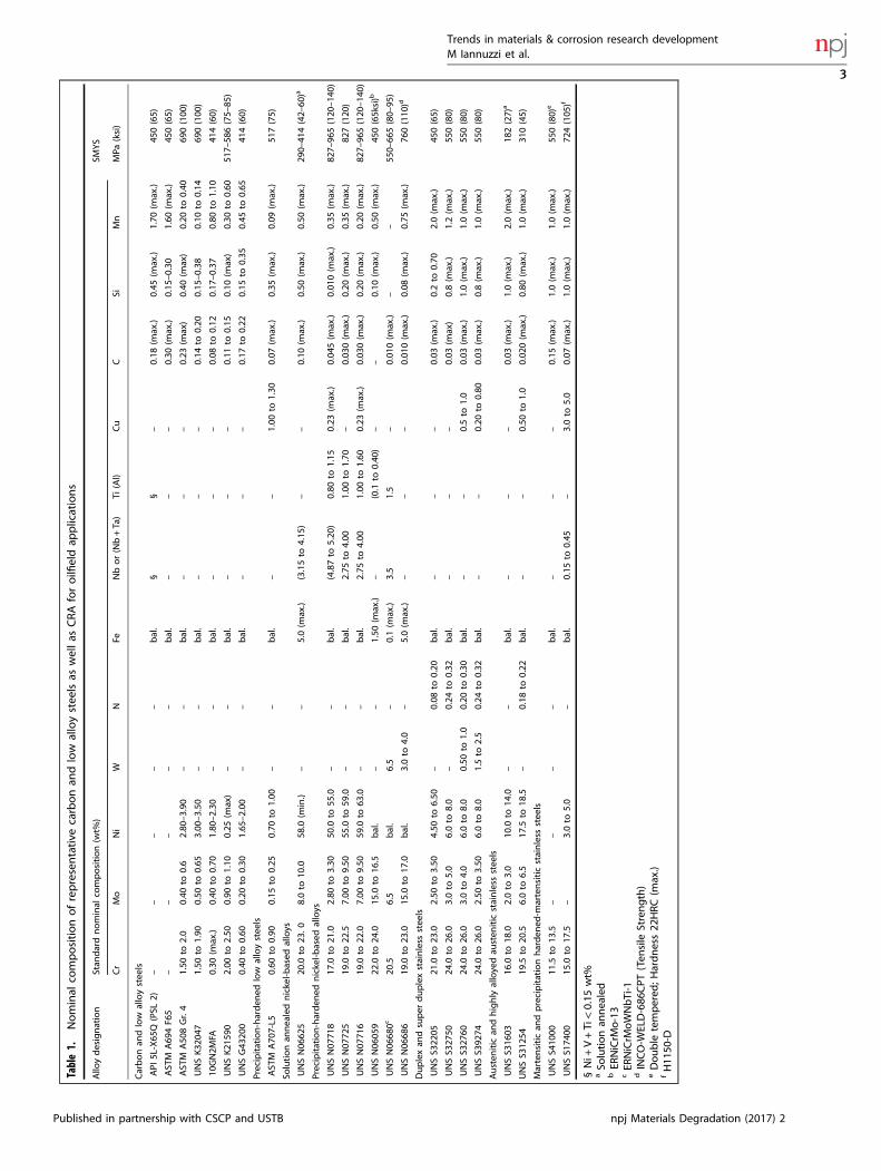
Table1.
Nominal
compositionofrepresentative
carbonan
dlow
alloystee
lsas
wellas
CRAforoilfi
eldap
plications
Allo
ydesignation
Stan
dardnominal
composition(w
t%)
SMYS
Cr
Mo
Ni
WN
FeNbor(Nb+Ta)
Ti(Al)
Cu
CSi
Mn
MPa
(ksi)
Carbonan
dlow
alloystee
ls
API
5L-X65
Q(PSL
2)–
––
––
bal.
§§
–0.18
(max.)
0.45
(max.)
1.70
(max.)
450(65)
AST
MA69
4F6
5–
––
––
bal.
––
–0.30
(max.)
0.15
–0.30
1.60
(max.)
450(65)
AST
MA50
8Gr.4
1.50
to2.0
0.40
to0.6
2.80
–3.90
––
bal.
––
–0.23
(max)
0.40
(max)
0.20
to0.40
690(100
)
UNSK32
047
1.50
to1.90
0.50
to0.65
3.00
–3.50
––
bal.
––
–0.14
to0.20
0.15
–0.38
0.10
to0.14
690(100
)
10GN2M
FA0.30
(max.)
0.40
to0.70
1.80
–2.30
––
bal.
––
–0.08
to0.12
0.17
–0.37
0.80
to1.10
414(60)
UNSK21
590
2.00
to2.50
0.90
to1.10
0.25
(max)
––
bal.
––
–0.11
to0.15
0.10
(max)
0.30
to0.60
517–
586(75–
85)
UNSG43
200
0.40
to0.60
0.20
to0.30
1.65
–2.00
––
bal.
––
–0.17
to0.22
0.15
to0.35
0.45
to0.65
414(60)
Precipitation-harden
edlow
alloystee
ls
AST
MA70
7-L5
0.60
to0.90
0.15
to0.25
0.70
to1.00
––
bal.
––
1.00
to1.30
0.07
(max.)
0.35
(max.)
0.09
(max.)
517(75)
Solutionan
nealednickel-b
ased
alloys
UNSN06
625
20.0
to23
.08.0to
10.0
58.0
(min.)
––
5.0(m
ax.)
(3.15to
4.15
)–
–0.10
(max.)
0.50
(max.)
0.50
(max.)
290–
414(42–
60)a
Precipitation-harden
ednickel-b
ased
alloys
UNSN07
718
17.0
to21
.02.80
to3.30
50.0
to55
.0–
–bal.
(4.87to
5.20
)0.80
to1.15
0.23
(max.)
0.04
5(m
ax.)
0.01
0(m
ax.)
0.35
(max.)
827–
965(120
–14
0)
UNSN07
725
19.0
to22
.57.00
to9.50
55.0
to59
.0–
–bal.
2.75
to4.00
1.00
to1.70
–0.03
0(m
ax.)
0.20
(max.)
0.35
(max.)
827(120
)
UNSN07
716
19.0
to22
.07.00
to9.50
59.0
to63
.0–
–bal.
2.75
to4.00
1.00
to1.60
0.23
(max.)
0.03
0(m
ax.)
0.20
(max.)
0.20
(max.)
827–
965(120
–14
0)
UNSN06
059
22.0
to24
.015
.0to
16.5
bal.
––
1.50
(max.)
–(0.1
to0.40
)–
–0.10
(max.)
0.50
(max.)
450(65ksi)b
UNSN06
680c
20.5
6.5
bal.
6.5
–0.1(m
ax.)
3.5
1.5
–0.01
0(m
ax.)
––
550–
665(80–
95)
UNSN06
686
19.0
to23
.015
.0to
17.0
bal.
3.0to
4.0
–5.0(m
ax.)
––
–0.01
0(m
ax.)
0.08
(max.)
0.75
(max.)
760(110
)d
Duplexan
dsuper
duplexstainless
stee
ls
UNSS3
2205
21.0
to23
.02.50
to3.50
4.50
to6.50
–0.08
to0.20
bal.
––
–0.03
(max.)
0.2to
0.70
2.0(m
ax.)
450(65)
UNSS3
2750
24.0
to26
.03.0to
5.0
6.0to
8.0
–0.24
to0.32
bal.
––
–0.03
(max)
0.8(m
ax.)
1.2(m
ax.)
550(80)
UNSS3
2760
24.0
to26
.03.0to
4.0
6.0to
8.0
0.50
to1.0
0.20
to0.30
bal.
––
0.5to
1.0
0.03
(max.)
1.0(m
ax.)
1.0(m
ax.)
550(80)
UNSS3
9274
24.0
to26
.02.50
to3.50
6.0to
8.0
1.5to
2.5
0.24
to0.32
bal.
––
0.20
to0.80
0.03
(max.)
0.8(m
ax.)
1.0(m
ax.)
550(80)
Austen
itic
andhighly
alloyedau
sten
itic
stainless
stee
ls
UNSS3
1603
16.0
to18
.02.0to
3.0
10.0
to14
.0–
–bal.
––
–0.03
(max.)
1.0(m
ax.)
2.0(m
ax.)
182(27)
a
UNSS3
1254
19.5
to20
.56.0to
6.5
17.5
to18
.5–
0.18
to0.22
bal.
––
0.50
to1.0
0.02
0(m
ax.)
0.80
(max.)
1.0(m
ax.)
310(45)
Martensitican
dprecipitationharden
ed-m
artensiticstainless
stee
ls
UNSS4
1000
11.5
to13
.5–
––
–bal.
––
–0.15
(max.)
1.0(m
ax.)
1.0(m
ax.)
550(80)
e
UNSS1
7400
15.0
to17
.5–
3.0to
5.0
–bal.
0.15
to0.45
–3.0to
5.0
0.07
(max.)
1.0(m
ax.)
1.0(m
ax.)
724(105
)f
§Ni+
V+Ti<0.15
wt%
aSo
lutionan
nealed
bER
NiCrM
o-13
cER
NiCrM
oWNbTi-1
dINCO-W
ELD-686
CPT
(Ten
sile
Strength)
eDouble
tempered
;Hardness22
HRC(m
ax.)
fH11
50-D
Trends in materials & corrosion research developmentM Iannuzzi et al.
3
Published in partnership with CSCP and USTB npj Materials Degradation (2017) 2

above 500–760mm). Likewise, ISO 15156’s restriction on theallowable nickel content excludes commercial LAS with anexceptional combination of properties such as strength, tough-ness, weldability, fatigue life, and hardenability.29 Some LAS suchas ASTM (American Society for Testing and Materials, WestConshohocken, PA) A508 Grade 4, 10GN2MF2 and MIL-S-16216K(i.e., a modified version of UNS K32047), Table 1, have beensuccessfully used in hydrogen-bearing atmospheres in, e.g.,nuclear reactor pressure vessels.34 ISO 15156 similarly excludeslow-carbon, copper-bearing, precipitation hardenable LAS basedon the ASTM A707 specification,35 which combine high strength,toughness, and weldability (Table 1).36 Adapting these types ofLAS for sour service applications by, for example, reducing theircarbon content, tailoring their carbon equivalent, and imposingstrict control of the elements responsible for temper embrittle-ment,37 could lead to significant weight reductions, improvedthrough-thickness properties, and extended fatigue life.32
The safe use of high strength LAS in sour service applicationsdepends primarily on understanding how composition, micro-structure, and thermo-mechanical processing affect hydrogenembrittlement (HE) resistance. In this regard, much debate stillexists about the influence of the complex microstructures of LASon SSC and HSC performance. The data compiled by Kappeset al.29 Fig. 1, suggest that tempered martensite and lower bainiteare the most SSC-resistant microstructures based on their thresh-old stress (σth) in H2S-saturated electrolytes. Normalized andtempered LAS or steels containing fresh martensite are severelyaffected by hydrogen. Snape has shown that small amounts ofuntempered martensite have dramatic effects on SSC perfor-mance, even on steels that met the macroscopic hardnessthreshold imposed by ISO 15156.30 Additionally, Fig. 1 indicatesthat the threshold stress of QT and bainitic steels was greater thanthe allowable stress in, e.g., Division 2 of the ASME Boiler andPressure Vessel Design Code, up to an AYS of about 700 to 750MPa. The threshold stress decreased rapidly above 750 MPa.Interestingly, the scatter seen in Fig. 1, particularly on bainitic
steels, is associated with the lack of a proper microstructurecharacterization. Indeed, most authors did not specify the type ofbainite, i.e., upper or lower, or martensite, i.e., plate, lath, or acombination, and some assumptions had to be made based onthe reported heat treatment procedures and alloy compositions toconstruct Fig. 1. Even today there are critical aspects of the bainiticand martensitic phase transformations in steels, such as the
carbide precipitation mechanisms, that remain unresolved and,according to some authors, might hold up technologicalprogress.38, 39
Even though experimental observations have shown that thealloy’s microstructure determines SSC and HSC resistance,researchers have yet to agree on a mechanistic explanation.Phenomenological observations speculate that the high residualstrain associated with untempered martensite, the presence ofcarbides at GB in upper bainite needles, and the type of ferrite-carbide interface in ferritic-pearlitic alloys could facilitatehydrogen-dislocation interactions.32
There seem to be a renaissance in LAS research, speciallybainitic LAS, with high- and ultra-high strength, fueled in part byindustry-academic synergies.40 Researchers have recently devel-oped, e.g., commercial oil country tubular goods (OCTG) withSMYS values up to 860MPa (125 ksi) that resist SSC in mild andintermediate sour service conditions41 thanks to advancements ingrain boundary engineering.42–45 The authors have found that thehigh dissipation energy of special high-angle grain boundaries(GB), i.e. more than 30°, reduced the driving force for crackpropagation. Figure 2 presents the qualitative distribution ofspecial GB obtained by electron backscatter diffraction (EBSD). Theideal amount and distribution of special GB depend not only onthe final QT heat treatment but also on the austenitization step.This example illustrates the importance of metallurgical design inobtaining high strength LAS with adequate EAC resistance. Futureinvestigations on richer LAS compositions for heavy forgedsections will benefit from advancements in this area.
Precipitation hardened (PH) corrosion resistant alloys (CRA)As a rule of thumb, large-bore (i.e., an internal diameter greaterthan approximately 50 cm) subsea production components, suchas valves, connectors, and pipes, are commonly made of LASoverlaid or cladded with a CRA.46 Full-cladded or partially-claddeddesigns take advantage of the strength and low cost of the LAScore, whereas the CRA inlay minimizes the corrosion concernsassociated with LAS exposure to aqueous electrolytes containingCO2 and H2S.
47 In subsea O&G production, LAS are typically weldoverlaid with UNS N06625 (NA625), a nickel-based seawaterresistant CRA (Table 1), but different stainless steels and nickelalloys could be used.22 Despite the fact that the surface exposedto production fluids is made of a CRA, the base LAS has to complywith the strength, hardness, and alloy chemistry requirements ofISO 15156.PH CRA are used when the application requires strength levels
exceeding the limits imposed by ISO 15156 on LAS, i.e., SMYSabove 690–760MPa (100–110 ksi). Both stainless steel and nickel-based PH alloys find numerous applications in O&G production. Inparticular, PH nickel-based alloys (PHNA) are extensively used inwellbore components due to their combination of strength andEAC resistance.48 Whereas all PHNA can sustain the mostaggressive production environments, not all PHNA families areseawater resistant.49
The most common PHNA is UNS N07718 (NA718), a super nickelalloy containing 17–21 wt% Cr, 2.8–3.3 wt% Mo, 50–55 wt% Ni, Nb,Ta, and Ti (Table 1).50 NA718 was first developed for high-temperature aerospace applications, and introduced in the O&Gindustry in the early 1980s.48 NA718 is strengthened by anordered, body-centered tetragonal γ“ phase, and an ordered face-centered cubic γ‘ phase.51 Despite its excellent performance insour production environments, NA718 suffers pitting and crevicecorrosion in oxidizing halide-containing environments due to itsintermediate Cr and Mo content. Indeed, NA718 has a localizedcorrosion performance similar to that of stainless steels ofcomparable Cr and Mo such as UNS S31600, Table 1.52
Alloys UNS N07725 (NA725) and UNS N07716 (NA716) arefrequently selected when the application requires improved
Fig. 1 Threshold stress (σth) of low alloy steels with differentmicrostructures exposed to 0.5 wt% CH3COOH + 5wt% NaCl in 1atm H2S at 24 °C, normalized to the actual yield strength (σy) versus σy
Trends in materials & corrosion research developmentM Iannuzzi et al.
4
npj Materials Degradation (2017) 2 Published in partnership with CSCP and USTB

localized corrosion performance (Table 1). Both PHNA derivedfrom NA625 and, like NA718, are strengthened by γ′ and γ″phase.53, 54 NA725 and NA716 can resist the most aggressive sourenvironments and are considered seawater resistant per ISO21457,46 based on their Pitting Resistance Equivalent.54, 55
Currently, no standard defines the maximum allowable tempera-ture for seawater service of NA725 and NA716; nevertheless,NA625 is restricted by ISO 21457 to 30 °C due to crevice corrosionconcerns in chlorinated systems.While it is well established that the presence of δ-phase
severely compromises NA718’s HSC and SSC resistance,56 PHNAhave been, a priori, considered immune to hydrogen embrittle-ment in the age-hardened conditions used in O&G applications.48
However, sudden cleavage failures of NA718,57 NA716,58 andNA72559 subsea components in relatively benign environmentshave been reported during installation and operation, allassociated with HE. Figures 3 and 4 illustrate a recent EACintergranular cleavage failure of an NA725 part. While in thesefailures the hydrogen source has not always been well established,it is suspected that H from either CP, electroplating, galvaniccoupling to carbon steel, or from degradation of non-productionfluids could have played a role.60 More alarmingly, in mostinstances, materials and manufacturing processes met interna-tional specifications, suggesting that existing best practices do notcapture all the variables that lead to an optimal microstructure.In the example shown in Figs. 3 and 4, the precipitation of a
continuous network of a nano-sized topologically close-packed(TCP) phase (i.e., σ-phase in this case) along GB may have led toHSC. Figure 4 shows the degree of GB coverage by σ-phase, whichwas 90 to 100%, and secondary crack propagation along thematrix/σ-phase interface. GB decoration was visible in the scanningelectron microscope (SEM) after special sample preparation stepsand could be characterized only by transmission electronmicroscopy (TEM). It is unclear whether the formation of σ-phaseis possible in the temperature and time ranges allowed in existingstandards but impossible to be detected up to now; or if residualstrain introduced during thermo-mechanical processing couldaccelerate precipitation kinetics well below the 30 h reported byMannan53 and Oradei–Basile.51 Moreover, despite the evidencesuggesting the deleterious effect of TCP phases, their role in EACand the mechanisms involved are still unclear. The O&G industrywill benefit from multi-disciplinary research activities aimed atelucidating the processing and manufacturing parameters thatresult in TCP precipitation and the mechanisms leading to EAC.
WeldingSince most pressure-containing components must be welded,weldability is one of the most important technological propertiesin the design of O&G equipment. Thus, increasing the strength ofthe base material requires a filler metal with comparable or bettermechanical properties. The necessity of joining dissimilar metals,particularly cladded LAS to stainless steels, exacerbates thechallenge.Welding and cladding of dissimilar materials are commonplace
in the subsea O&G industry. A typical example is the joining ofaustenitic and duplex or super duplex stainless steels (DSS andSDSS, respectively) to carbon or LAS, which can be either bare orcladded. The current approach is to use niobium-free nickel-basedCRA, e.g., UNS N06059 or UNS N06686 (Table 1), as a filler materialto prevent the hydrogen-related cracking of NA625-butteredjoints that has affected subsea production components.61, 62
When following present welding procedures, lean LAS compo-sitions such as API 5L63 Grade up to X65, and ASTM A694 (ref. 64)up to F65 do not require post-weld heat treatment (PWHT). Incontrast, richer chemistries, such as UNS K21590 (ASTM A182F22),65 are conventionally buttered with a 1%Ni–½%Cr LAS fillermetal (e.g., American Welding Society, Miami, FL) A.23:EG or EN
(European Standard, European Committee for Standardization,Brussels, Belgium) 756: S3NiMo1), and heat treated before weldingto the stainless steel part.66 Heat treating the buttered sectionbefore joining prevents sensitization during PHWT of, e.g., DSSand SDSS components.67
At present, the highest strength of dissimilar weld joints iscontrolled by the SMYS of the nickel-based CRA filler to about 470MPa (68 ksi). Although some researchers recommended under-matching the strength of the consumables used to weld highstrength LAS,68 this practice is discouraged by current designcodes.69 Therefore, the SMYS of the base metal is restricted to a
Fig. 2 Qualitative distribution of special grain boundaries (Σ: 3 inred, Σ :11, 25b, 33c and 41c in blue) in a QT pipeline steel obtainedby electron backscatter diffraction. Image Courtesy of Tenaris
Fig. 3 Hydrogen embrittlement of UNS N07725 showing signs ofintergranular cleavage. Image courtesy of General Electric
Trends in materials & corrosion research developmentM Iannuzzi et al.
5
Published in partnership with CSCP and USTB npj Materials Degradation (2017) 2

slightly lower strength, to prevent making the weldment theweaker part of the joint.70
Mannan and coworkers have recently introduced a new PHnickel-based Ni–Cr–Mo–W–Nb–Ti filler metal designated as UNSN06680 (NA680), Table 1.71 According to the authors, NA680 canbe used to weld clad-OCTG with an SMYS, in the as weldedcondition, of up to 550 MPa (80 ksi). The alloy can reach highstrength levels due to self-aging or auto-aging during cooling.Nevertheless, the AYS of the joint was strongly affected by theheat input of the process. The maximum reported yield strengthwas about 655 MPa (95 ksi) but, in some instances, it did not reach550MPa (80 ksi). Despite the promising results presented byMannan and coworkers, there are no universally acceptedpractices to weld clad-LAS with SMYS above approximately 450MPa (65 ksi) to stainless steels. The successful introduction of high-strength LAS in subsea O&G equipment will, in a great measure,depend on the development of high strength filler metals andnew welding procedures.
PUSHING THE LIMITS OF CRAA multitude of CRA are used in oilfield applications, includingmartensitic, austenitic, ferritic, duplex, and PH stainless steels,solution annealed and PHNA, as well as titanium, cobalt, andaluminum alloys. Examples of typical CRA are shown in Table 1.Materials selection of CRA is primarily governed by part 3 of theISO 15156 standard (ISO 15156-3)26 and ISO 21457.46 The scope ofthe ISO 15156-3 specification includes clearly opposing mechan-isms such as stress corrosion cracking (SCC), SSC, and galvanically-induced hydrogen stress cracking (GHSC). The philosophy of ISO15156-3 is to set strict limits on the parameters that influencethese forms of corrosion; i.e., the partial pressure of H2S, solutionpH, chloride concentration, temperature, and the presence orabsence of S0. Likewise, ISO 15156-3 restricts strength andhardness in certain alloy systems. The materials’ boundariesestablished by the standard derive from a combination of industryexperience and qualification testing and have been initiallyresisted by the industry.14, 72
One of the chief criticisms to ISO 15156-3 is that it represents a“one-size-fits-all” approach to materials selection. Thus, exceedingone of the environmental limits presented in Annex A of thestandard implies that (i) the chosen alloy is unfit for service or (ii)the alloy requires additional qualification testing. Annex B detailsthe recommended qualification testing procedures. However, thetesting methodology, the exposure conditions, the extent of
validity (i.e., per heat, heat treatment lot, manufacturer, etc.), aswell as the essential variables that trigger re-qualification must beagreed upon by the operator, the OEM, and the alloy producer. Inpractice, because qualification testing is costly and time-consuming and, as importantly, because no clear quality controlpractices exist to certify materials during production, designerstypically avoid testing altogether and opt for a more resistant CRAinstead. Interestingly, this approach is currently being challengedby the API 17TR8 Task Group, which has specified comprehensiveEAC testing for HPHT applications in simulated productionenvironments, seawater with CP, as well as corrosive non-production fluids.7
Irrespectively of any criticism to the degree of conservatism inISO 15156-3 Annex A,22 the broad scope of the standard isquestionable. GHSC, i.e., a form of HSC in which nascent H isproduced at the CRA surface due to galvanic coupling to a lessresistant alloy,28 and SSC are exacerbated at lower temperaturesthan those observed in the wellbore near the reservoir. BecauseGHSC can occur in the absence of uniform or localized corrosionof the CRA, a material could meet ISO 15156-3 restrictionsregarding environmental conditions and maximum allowabletemperature, yet be susceptible to GHSC if subjected to galvaniccoupling. In this regard, high strength alloys such as martensiticstainless steels are particularly susceptible to GHSC.73
ISO 15156-3 mandates GHSC testing to ballot new materials forinclusion in the standard. However, not all materials listed in thespecification have been evaluated for GHSC. In such instances, theboundaries were established based on industry experience.14
Lastly, it is important to emphasize that SSC of CRA can only occurbelow the depassivation pH (pHd), which for many of the highergrade CRA can be as low as 1.74 Given the recent HSC failures ofPHNA,57–59 which are amongst the most resistant materials listedin ISO 15156-3, in relatively benign conditions, it is stronglyadvisable that the ISO and NACE maintenance committees revisitthe implications of the current extent of the standard.In contrast to SSC and GHSC, SCC is an anodic process mainly
controlled by the stability of the passive film and the localchemistry. Researchers have found that pitting corrosion appearsto be a prerequisite for SCC in production environments, as theconditions that stabilize a pit are similar to those required forSCC. 75, 76 Anderko, Sridhar and coworkers have developed aframework that uses the repassivation potential (ERP) and thecorrosion potential (ECorr) to estimate the likelihood of SCC in sourproduction environments.77–79 The main assumption is that SCCoccurs only in the presence of localized corrosion when the
Fig. 4 Microstructure characterization of the affected UNS N07725 samples: a almost full grain boundary coverage by a topologically close-packed phase (TCP), and b secondary HE cracking propagating along the matrix-TCP interface. Images courtesy of General Electric
Trends in materials & corrosion research developmentM Iannuzzi et al.
6
npj Materials Degradation (2017) 2 Published in partnership with CSCP and USTB

temperature is above the critical pitting temperature and ECorr >ERP. The authors have validated a quantitative model that predictsboth ERP and ECorr of martensitic stainless steels as a function ofsolution chemistry and temperature.78, 79
The approach developed by Anderko et al. has tremendouspotential as it could be used to revise ISO 15156-3 limits andoptimize materials selection. Additionally, the combination of arobust quantitative model and, e.g., sensors could be implemen-ted in new corrosion risk management tools. For example,reference electrodes added to oilfield equipment could monitorECorr over time. ECorr data could, then, be compared to ERP values,estimated as a function of the actual composition of the producedfluids. More research is needed to extend the approach to otherCRA families, in particular, DSS and SDSS since their currentenvironmental boundaries are perceived as being excessivelyconservative.80
Effect of hydrogen on the localized corrosion resistance of CRAAlthough hydrogen generated by either corrosion or by CP hasbeen shown to deteriorate the protectiveness of passive films,existing EAC models do not take this effect into consideration. Yaoet al.,81 Guo et al.,82 Pyun et al.,83, 84 Thomas et al.,85 Armacanquiand Oriani,86 to name a few, have shown that in part due to itsstrong reducing properties, hydrogen present in the passive filmlowers the resistance to pitting corrosion. Yao et al. attributed thedecrease in localized corrosion resistance of UNS S32205 to achange in the semiconductor properties of the chromium oxidefilm.81 The authors showed that ECorr decreased and the passivecurrent density increased due to pre-charging. Similar results werealso seen by Thomas et al. on CS.85 Interestingly, anecdotalevidence from recent failure investigations on SDSS seawaterpumps seems to confirm the deleterious effect of hydrogen onlocalized corrosion resistance. In this regard, severe localizedcorrosion was found after removal of the CP system underconditions a priory benign to SDSS. The recent work by Thomaset al.87 can be consulted for a more comprehensive overview ofthe role of hydrogen on corrosion of CS and LAS, as well as CRA.More research is needed to comprehend the influence of
hydrogen on localized corrosion resistance fully and, conse-quently, its influence of EAC. In this regard, the presence of H2Scould further complicate the issue as the effect of H on, e.g.,Fe1 + xS films has yet to be investigated. However, the markeddecrease in ECorr and the increase in passive current densityreported for stainless steels and CS open the door to in situcorrosion monitoring techniques. It is plausible to envision, forexample, a simple ECorr monitoring device that, when coupled toproper corrosion models, could be used to determine localizedcorrosion and EAC risks.
ON THE TRAIL OF HYDROGENIndustry-academia synergies are essential to overcome thechallenges discussed in previous sections. Methodologies basedon SEM and TEM, focused ion beam (FIB), as well as atomic forcemicroscopy, coupled with in situ micro-mechanical and nano-mechanical and electrochemical techniques have matured rapidlyover the last decade. Today, researchers have at their disposal anexceptional toolkit that allows multi-scale characterization, fromthe nanoscale to full-size industrial settings, of complex phenom-ena like HE.88 The combination of approaches is helping shed newlight on the compound microstructure-environment interactionsleading to EAC. This section discusses recent advancements inhydrogen embrittlement research with a focus on ECNI, nano-mechanical characterization, and electrochemical microcantileverbending.
Hydrogen effects in metals: an elusive phenomenonHydrogen is the smallest atom in the universe, and its small sizemakes it a controversial interstitial in comparison to the othercommon interstitial atoms. While all other interstitial elements,e.g., C, N, and B seem to have beneficial effects on the mechanicalproperties of metals and, more specifically, steels, the presence ofH results in a severe degradation of strength and toughness. Arecent ab initio simulation shows that the small size of the H atomin the crystal lattice results in the formation of nonsymmetricalbonds between H and the host metal atoms.89–91 Additionally, H isa mobile interstitial at room temperature. Apart from thecomplications arising from the H uptake and transport processesin the metal, the interaction of the dissolved H atom with thecrystal lattice and crystal defects, e.g., dislocations and GB, andconsequently its effect on mechanical properties is a highly-complicated process. Traditionally, conventional macro-scalemechanical tests have been used to study the effect of dissolvedhydrogen on the mechanical behavior of metals and alloys.However, it is almost impossible to decouple such macroscopictests from the H uptake and transport processes. Moreover, aconventional test measures the response of a macroscale sample
Fig. 5 Load-displacement curves resulting from nanoindentation onUNS N07718 in the aged hardened condition. Clear pop-ins in therange of 190 to 270 µN are observed
Fig. 6 Effect of applied potential on dislocation nucleation in a modelFe–3wt% Si alloy. Applied potentials as indicated. For the green curve,the applied potential was switched to 1000mVHg/HgSO4 in the anodicdirection after an initial cathodic polarization of −1000mVHg/HgSO4,followed by a cathodic polarization of −1300mVHg/HgSO4
Trends in materials & corrosion research developmentM Iannuzzi et al.
7
Published in partnership with CSCP and USTB npj Materials Degradation (2017) 2

to a mechanical load, while the H interaction with the lattice is adiscrete localized process distributed over time and space. Heffects take place in specific H-enriched locations of the sample. Inother words, the signal to noise ratio in macroscopic tests is
considerably low. Undeniably, very useful qualitative informationand design parameters can be extracted from conventional tests;however, a mechanistic understanding of the HE phenomenonrequires tools with a higher signal-to-noise ratio. A typical, but nottrivial, approach is, thus, to reduce the size of the sample andperform micro- and nanoscale mechanical evaluations.92–95
Challenges of small-scale testingOnce the size of the specimen or the volume of the material isreduced, the most challenging task is to retain the H atoms in suchsmall dimensions. Except for some special alloys and metals,96, 97
it is impossible to stop hydrogen outgassing from a small sample.Therefore, a microscale mechanical evaluation of the influence ofH in mechanical properties should be combined with in situ Hcharging.
Studying hydrogen-dislocation interactions: ECNIUndoubtedly, nanoindentation has been the most popular andfrequently used small-scale testing method over the lastdecades.98 Combined with scanning probe microscopy andimaging capabilities with the same tip used for indentation;nanoindentation is a unique mechanical testing method thatprovides a high-resolution characterization.99
A typical nanoindentation test consists of several steps. First, afterimaging the surface topography, the tip can be located withFig. 7 Microcantilever geometry and dimensions
Fig. 8 In situ microcantilever bending of Fe–3 wt% Si: a cantilever bent in air, b higher magnification micrograph of the root of the FIB notchbent in air, c H-charged cantilever bent in the electrolyte under cathodic polarization, and d higher magnification micrograph of the root ofthe FIB notch (H-charged)
Trends in materials & corrosion research developmentM Iannuzzi et al.
8
npj Materials Degradation (2017) 2 Published in partnership with CSCP and USTB
nanometer precision. Subsequently, multiple indentationscan be performed while registering the indentation loadand displacement of the tip. In well-prepared samples withlow dislocation density, the probability of indenting a dislocation-free region is very high. In such instances, the indentation starts withan elastic loading that follows the Hertzian contact model. 100–106
As the shear stress below the tip in the volume of the materialapproaches the theoretical stress required for homogeneousdislocation nucleation, a sudden jump, i.e., the so-called pop-in, inthe displacement occurs. The pop-in marks the transition fromelastic to elastoplastic deformation in a perfect crystal. Then, theindentation continues in the elastoplastic regime up to themaximum indentation load. The unloading curve can be assumedto be fully elastic and is typically used to extract the hardnessand elastic modulus of the material per the Oliver–Pharrmethod.107 Typical load-displacement curves of NA718 are shownin Fig. 5.ECNI combines nanoindentation with in situ electrochemical
hydrogen charging. ECNI provides distinct possibilities for study-ing the influence of H on mechanical properties, especially theeffect of hydrogen on dislocation nucleation. The results of in situECNI on a research-grade Fe–3wt.% Si alloy, Fig. 6, show that therequired load for pop-in, i.e., homogeneous dislocation nucleation,is reduced in the presence of H. Additionally, the amount of thereduction in the pop-in load scales with the amount of hydrogenwhich is controlled by the applied electrochemical polarization.Per the defactant theory,108–111 the decrease in the load requiredfor dislocation nucleation can be related to the reduction in thedislocation line energy by H.96, 112, 113
Hydrogen effects on crack propagation: microcantilever bendingtestsFIB cut micro-samples, loaded inside a nanoindenter equippedwith special tips have traditionally been used to study size-effectsin metals and alloys.114–118 The possibility of in situ electro-chemical H charging inside a nanoindenter provides a uniqueopportunity to perform such microscale experiments on H-charged samples, Fig. 7.Figure 8 shows a cantilever cut in a Fe–3 wt% Si model alloy
after bending in air and under continuous H charging. Thepresence of hydrogen resulted in the nucleation of a crack at theroot of the notch in the beam. Postmortem high-resolution sub-microstructural examination, e.g., EBSD93 and TEM92 could beperformed on these cantilevers to reveal the mechanism ofhydrogen embrittlement at the dislocation level.Presently, in situ microcantilever bending has been successfully
applied to relatively simple model materials and monocrystallinemicrocantilevers. In the future, alloys with more complexmicrostructures, e.g., PH-CRA, as well as bi-crystalline cantileverswill be used to study the role of different microstructural featuresduring the hydrogen embrittlement process and their interactionwith the crack tip in the presence of hydrogen.
CONCLUSIONSHigh strength materials, including LAS and PH-CRA, are essentialto overcome the materials hurdles associated with the productionof hydrocarbons from unconventional reservoirs.EAC and localized corrosion are the two primary degradation
forms that affect the alloys required for the safe and economicoperation of sour, HPHT, and Arctic fields. A better understandingof the metallurgical factors and manufacturing variables that leadto optimal EAC resistance is paramount.In situ characterization techniques, such as ECNI and micro-
cantilever bending, can provide unique insights into the crackinitiation and propagation mechanisms. Nevertheless, muchresearch is still required to extend the findings of nano-scale
and micro-scale testing to the macroscopic corrosion performanceof engineering alloys.Strengthening the close collaboration between industry and
academia is essential to develop a multi-scale understanding ofthe compound microstructure-environment interactions to lead tooptimal EAC resistance.
ACKNOWLEDGEMENTSThe authors thank Atle H. Qvale (General Electric, Oil & Gas) and Dr. Martin Morra(General Electric, Global Research Center), as well as Dr. María José Cancio (Tenaris)for their invaluable contribution and discussions. We would also like to thank Prof.Nick Birbilis for his encouragement and for inviting us to submit our work. GeneralElectric and the Norwegian University of Science and Technology sponsored thepublication of this manuscript equally. We thank the support of the Research Councilof Norway to the NTNU NanoLab through the Norwegian Micro-Fabrication andNano-Fabrication Facility, Norfab (197411/V30) and projects HIPP (234130/E30) andHyF-Lex (244068/E30).
AUTHOR CONTRIBUTIONSAll authors contributed equally to this manuscript.
ADDITIONAL INFORMATIONCompeting interests: The authors declare no competing financial interests
Publisher’s Note: Springer Nature remains neutral with regard to jurisdictionalclaims in published maps and institutional affiliations.
REFERENCES1. U.S. Bureau of Labor Statistics. Employer-reported workplace injuries and
illnesses–2015. Report No. USDL-16-2056, (Washington, D.C., 2016).2. U.S. Chemical Safety and Hazard Investigation Board. Investigation report
volume 2-Explosion and fire at the Macondo well. Report No. 2010-10-I-OS,(Washington, D.C., 2014).
3. Bell, J. M., Chin, Y. D. & Hanrahan, S., State-of-the-Art of Ultra Deepwater Pro-duction Technologies. in Offshore Technology Conference, 2–5 (Society of Pet-roleum Engineers, 2005).
4. Iannuzzi, M. in Stress Corrosion Cracking. Theory and Practice (eds Raja, V. S. &Shoji, T.) Ch. 15, 570–607 (Woodhead Publishing, 2011)
5. Michie, D. Economic Report 2016 (Oil & Gas, London, U.K., 2016).6. Skeels, H. B. API 17TR8-HPHT Design Guideline for Subsea Equipment. in Off-
shore Technology Conference, OTC-25376-MS (Houston, TX, Offshore TechnologyConference, 2014).
7. API 17TR8, High-pressure High-temperature Design Guidelines (American Petro-leum Institute, 2015).
8. Kfoury, M. Kristin HPHT Gas Condensate Field: challenges, remedial actions &strategy to improve hydrocarbon reserve (Statoil AS, 2012).
9. Lehr, D. J. & Collins, S. D., The HPHT Completion Landscape-Yesterday, Today,and Tomorrow. in SPE Annual Technical Conference and Exhibition, SPE-170919-MS, 27–29 (Society of Petroleum Engineers, 2014).
10. Avant, C. et al. Testing the limits in extreme well conditions. Oilfield Rev. 24, 4–19(2012).
11. Mazerov, K. HPHT completions: always a moving target. Drill. Contractor (2011).http://www.drillingcontractor.org/hpht-completions-always-a-moving-target-9344.
12. NACE/ASTM G193−12d, Standard Terminology and Acronyms Relating to Corro-sion (ASTM International, 2012).
13. Wilhelm, S. M. & Kane, R. D. Selection of Materials for Sour Service in PetroleumProduction. J. Pet. Technol. 38, 1051–1061 (1986).
14. NACE International Work Group T-1F-21G. Use of Corrosion-ResistantAlloys in Oilfield Environments. Report No. 1F192, (NACE International 2000).
15. European Federation of Corrosion. Guidelines on Materials Requirementsfor Carbon and Low Alloy Steels for H2S-Containing Environments in Oil and GasProduction. 3rd edn., Vol. Publication No. 16 (Maney Publishing, 2009).
16. Smith, L. & Craig, B. D., Practical corrosion control measures for elemental sulfurcontaining environments. in CORROSION 3–7 (NACE International, 2005).
17. Walton, D., Equipment and material selection to cope with high pressure/hightemperature surface conditions. in Offshore Technology Conference, OTC-12122-MS (Offshore Technology Conference, 2000).
Trends in materials & corrosion research developmentM Iannuzzi et al.
9
Published in partnership with CSCP and USTB npj Materials Degradation (2017) 2

18. Horn, A. M., Østby, E., Hauge, M. & Aubert, J.-M. in The Twenty-second Interna-tional Offshore and Polar Engineering Conference 290–296 (International Societyof Offshore and Polar Engineers, 2012).
19. Thaulow, C., Ødegård, J. & Østby, E., Arctic steels criteria for safe materialsutilisation. in High Technologies in Advanced Metal Science and Engineering(St. Petersburg, Russia, 2006).
20. Alvaro, A., Akselsen, O. M., Ren, X. & Kane, A. in Proceedings of the Twenty-fourthInternational Ocean and Polar Engineering Conference 247–254 (InternationalSociety of Offshore and Polar Engineers, 2014).
21. Gangloff, R. P. in Comprehensive Structural Inteqrity Vol. 6 (eds Milne, I., Ritchie, R.O. & Karihaloo, B) Ch. 6.02, 31–101 (Elsevier Science, 2003).
22. Rhodes, P. R., Skogsberg, L. A. & Tuttle, R. N. Pushing the limits of metals incorrosive oil and gas well environments. Corrosion 63, 63–100 (2007).
23. Davenport, E. S., Fundamental Characteristics of Alloy Steel. in Drilling andProduction Practice, API-35-209, 209–225 (American Petroleum Institute, 1935).
24. Craig, B. D. On the contradiction of applying rolled threads to bolting exposedto hydrogen-bearing environments. Oil Gas Facilities 4, 66–71 (2015).
25. Vollmer, L. W. Hydrogen sulphide corrosion cracking of steel. Corrosion 8,326–332 (1952).
26. Milliams, D. E. & Tuttle, R. N., ISO 15156/NACE MR0175-A new internationalStandard for metallic materials for use in oil and gas production in sourenvironments. in CORROSION, 03090, 16–20 (NACE International, 2003).
27. Craig, B. D. in Sour-gas design considerations SPE Monograph Series Ch. 1, 1–3(Society of Petroleum Engineers, 1993).
28. ISO 15156 (1-3), Petroleum and natural gas industries - Materials for use in H2S-containing environments in oil and gas production (International Organization forStandardization, 2015).
29. Kappes, M., Iannuzzi, M., Rebak, R. B. & Carranza, R. M. Sulfide stress cracking ofnickel-containing low-alloy steels. Corros. Rev. 32, 101–128 (2014).
30. Snape, E. Sulfide stress corrosion of some medium and low alloy steels. Corro-sion 23, 154–172 (1967).
31. Kane, R. D., Wilhelm, S. M. & Oldfield, J. W., Review of Hydrogen InducedCracking of Steels in Wet H2S Refinery Service. in International Conference onInteraction of Steels with Hydrogen in Petroleum Industry Pressure Vessel Service(Materials Properties Council, 1989).
32. Craig, B. D. & Krauss, G. The structure of tempered martensite and its suscept-ibility to hydrogen stress cracking. Metall. Trans. A 11, 1799–1808 (1980).
33. Craig, B., Brownlee, J. & Bruno, T. Sulfide stress cracking of nickel steels. Corro-sion 48, 90–97 (1992).
34. Lee, K.-H., Park, S.-g, Kim, M.-C., Lee, B.-S. & Wee, D.-M. Characterization oftransition behavior in SA508 Gr.4N Ni–Cr–Mo low alloy steels with micro-structural alteration by Ni and Cr contents. Mater. Sci. Eng. A 529, 156–163(2011).
35. ASTM A707/A707M-14, Standard Specification for Forged Carbon and Alloy SteelFlanges for Low-Temperature Service (ASTM International, 2014).
36. Walsh, F. & Price, S. in Steel Forgings: Second Volume Vol. STP16601S (eds Nisbett,E. G. & Melilli, A. S.) 196–209 (ASTM International, 1997).
37. Raabe, D. et al. Grain boundary segregation engineering in metallic alloys: Apathway to the design of interfaces. Curr. Opin. Solid State Mater. Sci. 18,253–261 (2014).
38. Bhadeshia, H. K. D. H. The bainite transformation: unresolved issues. Mater. Sci.Eng. A 273-275, 58–66 (1999).
39. Fielding, L. C. D. The bainite controversy. Mater. Sci. Technol. 29, 383–399 (2013).40. Caballero, F. G., García-mateo, C., Capdevila, C. & Andrés, C. Gd Advanced
Ultrahigh Strength Bainitic Steels. Mater. Manuf. Process. 22, 502–506 (2007).41. Cancio, M. J., Giacomel, B., Kissner, G., Valdez, M. & Vouilloz, F., High strength low
alloy steel for HPHT wells. in Offshore Technology Conference-Asia, OTC-24746-MS, (Offshore Technology Conference, 25–28, 2014).
42. Randle, V. Grain boundary engineering: an overview after 25 years. Mater. Sci.Technol. 26, 253–261 (2013).
43. King, A. H. & Shekhar, S. What does it mean to be special? The significance andapplication of the Brandon criterion. J. Mater. Sci. 41, 7675–7682 (2006).
44. Bechtle, S., Kumar, M., Somerday, B. P., Launey, M. E. & Ritchie, R. O. Grain-boundary engineering markedly reduces susceptibility to intergranular hydro-gen embrittlement in metallic materials. Acta Mater. 57, 4148–4157 (2009).
45. Watanabe, T. Grain boundary engineering: historical perspective and futureprospects. J. Mater. Sci. 46, 4095–4115 (2011).
46. ISO 21457:2010, Petroleum, Petrochemical And Natural Gas Industrie–MaterialsSelection and Corrosion Control For Oil and Gas Production Systems (InternationalOrganization for Standardization, 2010).
47. Nešić, S. Key issues related to modelling of internal corrosion of oil and gaspipelines – A review. Corros. Sci. 49, 4308–4338 (2007).
48. Bhavsar, R. B., Collins, A. & Silverman, S., Use of alloy 718 and 725 in oil and gasindustry. in Proceedings of the International Symposium: Superalloys 718, 625, 706
and Various Derivatives., 47–55 (The Minerals, Metals and Materials Society(TMS), 2001).
49. Malik, A. U., Siddiqi, N. A., Ahmad, S. & Andijani, I. N. The effect of dominant alloyadditions on the corrosion behavior of some conventional and high-alloystainless-steels in seawater. Corros. Sci. 37, 1521–1535 (1995).
50. API 6ACRA, Age-hardened Nickel-based Alloys for Oil and Gas Drilling and Pro-duction Equipment (American Petroleum Institute, 2015).
51. Oradei-Basile, A. & Radavich, J. F., A current TTT diagram for wrought alloy 718.in Proceedings of the International Symposium: Superalloys 718, 625 and Var-ious Derivatives, 325–335 (The Minerals, Metals and Materials Society (TMS),1991).
52. Rebak, R. B. et al. Effect of thermal treatment on the localized corrosion behaviorof alloy 718 (UNS N07718). in EUROCORR 2014, 8–12 (European Federation ofCorrosion, 2014).
53. Mannan, S. & Veltry, F. Time-temperature-transformation diagram of alloy 725.in Proceedings of the International Symposium: Superalloys 718, 625, 706 andVarious Derivatives., 345–356 (The Minerals, Metals and Materials Society (TMS),2001).
54. Dong, J. X., Zhang, M. C. & Mannan, S. K. Microstructures and the structurestability of Inconel 725 a new age-hardenable corrosion resistant superalloy.Acta Metall. Sin. 16, 145–150 (2003).
55. Jargelius-Pettersson, R. F. A. Application of the pitting resistance equivalentconcept to some highly alloyed austenitic stainless steels. Corrosion 54, 162–168(1998).
56. Galliano, F. et al. Effect of trapping and temperature on the hydrogen embrit-tlement susceptibility of alloy 718. Mater. Sci. Eng. A 611, 370–382 (2014).
57. Cassagne, T., Bonis, M. & Duret, C. Understanding field failures of alloy 718forging materials in HP/HT wells. in EUROCORR 2008, 1–13 (European Federationof Corrosion, 7–11, September 2008).
58. Nice, P. et al. Hydrogen embrittlement failure of a precipitation hardened nickelalloy subsurface safety valve component installed in a North Sea seawaterinjection well. in CORROSION, 3892 (NACE International, 2014).
59. Shademan, S. S., Martin, J. W. & Davis, A. P. UNS N07725 Nickel Alloy ConnectionFailure. in CORROSION, C2012-0001095 (NACE International, 2012).
60. Osen, I. & Frydenberg, T. Nickel Alloy 725 Connection Failure: Root CauseAnalysis Report. Report No. G1-VW-U-US00-C35-0419_rev3, (General Electric,Sandvika, Norway, 2015).
61. Olden, V., Kvaale, P. E., Simensen, P. A., Aaldstedt, S. & Solberg, J. K. The Effect ofPWHT on the material properties and micro structure in inconel 625 and inconel725 Buttered Joints. in 22nd International Conference on Offshore Mechanics andArctic Engineering, OMAE2003-37196, 109–115 (ASME International, 2003).
62. Beaugrand, V. C., Smith, L. S. & Gittos, M. F. Subsea dissimilar joints: failuremechanisms and opportunities for mitigation. in CORROSION, 9305, 22–26(NACE International, 2009).
63. API 5L, Specification for Line Pipe (American Petroleum Institute, 2013).64. ASTM A694/A694M-16, Standard Specification for Carbon and Alloy Steel Forgings
for Pipe Flanges, Fittings, Valves, and Parts for High-Pressure Transmission Service(ASTM International, 2016).
65. ASTM A182/182M, Standard Specification for Forged or Rolled Alloy and StainlessSteel Pipe Flanges, Forged Fittings, and Valves and Parts for High-TemperatureService (ASTM International, 2016).
66. Rosenqvist, F., Estrada, S. & Haeberle, T. GE Oil & Gas Quality ManagementSystem Engineering Welding Standard. Material Selection and Buttering Prac-tices for Low Alloy Steel Flanges, Hubs, & Other Subsea Components to beWelded to Piping Without PWHT. Report No. QW-ENG-7.3.5-008, (GeneralElectric, 2014).
67. Lippold, J. C. & Kotecki, D. J. Welding Metallurgy and Weldability of Stainless SteelsCh. Duplex Stainless Steels, 230–245 (Wiley, 2005).
68. Umekuni, A. & Masubuchi, K. Usefulness of undermatched welds for high-strength steels. Weld. J. 76, S256–S263 (1997).
69. ASME ASME Boiler and Pressure Vessel Code. Section II. Part D: Properties(Metric) Materials (ASME International, 2009).
70. Hartbower, C. & Pellini, W. Explosion bulge test studies of the deformation ofweldments. Weld. J. 30, 307S–318S (1951).
71. Mannan, M. A., Golihue, R., Kiser, S., McCoy, S. A. & Phillipp, J., A new nickel alloyfiller metal designed for welding high strength ID-clad steels. in EUROCORR,50697, 11–15 (European Federation of Corrosion, 2016).
72. Vatne, J. & Verdolin, R., Difficulties In The Use Of NACE MR0175/ISO 15156. inCORROSION, 11112, 13–17 (NACE International, 2011).
73. Sagara, M. et al. Evaluation of Susceptibility to Hydrogen Embrittlement of HighStrength Corrosion Resistant Alloys. in CORROSION, 7847, 6–10 (NACE Interna-tional, 2016).
74. Denpo, K. & Ogawa, H. Crevice corrosion of corrosion-resistant alloys in sourenvironments. Corrosion 47, 592–597 (1991).
Trends in materials & corrosion research developmentM Iannuzzi et al.
10
npj Materials Degradation (2017) 2 Published in partnership with CSCP and USTB
75. Miyasaka, A., Denpo, K. & Ogawa, H. Environmental aspects of SCC of high alloysin sour environments. Corrosion 45, 771–780 (1989).
76. Tsujikawa, S. et al. Alternative for evaluating sour gas resistance of low-alloysteels and corrosion-resistant alloys. Corrosion 49, 409–419 (1993).
77. Cao, L., Anderko, A., Gui, F. & Sridhar, N. Localized corrosion of corrosion resis-tant alloys in H2S-containing environments. Corrosion 72, 636–654 (2016).
78. Anderko, A., Cao, L., Gui, F., Sridhar, N. & Engelhardt, G. Modeling localizedcorrosion of corrosion-resistant alloys in oil and gas production environments: II.corrosion potential. Corrosion (2016).
79. Anderko, A., Gui, F., Cao, L., Sridhar, N. & Engelhardt, G. R. Modeling localizedcorrosion of corrosion-resistant alloys in oil and gas production environments:part i. repassivation potential. Corrosion 71, 1197–1212 (2015).
80. Siegmund, G., Schmitt, G. & Kuhl, L., Unexpected Sour Cracking Resistance ofDuplex and Superduplex Steels. in CORROSION, 7631, 6–10 (NACE International,2016).
81. Yao, J., Dong, C., Man, C., Xiao, K. & Li, X. The electrochemical behavior andcharacteristic of passive film on 2205 duplex stainless steel under varioushydrogen charging conditions. Corrosion 72, 42–50 (2016).
82. Guo, L. Q. et al. Effect of hydrogen on pitting susceptibility of 2507 duplexstainless steel. Corros. Sci. 70, 140–144 (2013).
83. Moon, S. M. & Pyun, S. I. The corrosion of pure aluminium during cathodicpolarization in aqueous solutions. Corros. Sci 39, 399–408 (1997).
84. Pyun, S.-I., Lim, C. & Oriani, R. A. The role of hydrogen in the pitting of passi-vating films on pure iron. Corros. Sci. 33, 437–444 (1992).
85. Thomas, S. et al. The effect of absorbed hydrogen on the dissolution of steel.Heliyon 2, e00209 (2016).
86. Armacanqui, M. E. & Oriani, R. A. Technical note:effect of hydrogen on thepitting resistance of passivating film on nickel in chloride-containing solution.Corrosion 44, 696–698 (1988).
87. Thomas, S., Sundararajan, G., White, P. D. & Birbilis, N. The effect of absorbedhydrogen on the corrosion of steels: review, discussion, and implications. Cor-rosion 73, 426–436 (2017).
88. Djukic, M. B., Bakic, G. M., Zeravcic, V. S., Sedmak, A. & Rajicic, B. Hydrogenembrittlement of industrial components: prediction, prevention, and models.Corrosion 72, 943–961 (2016).
89. Geng, W.-T., Freeman, A. J., Olson, G. B., Tateyama, Y. & Ohno, T. Hydrogen-promoted grain boundary embrittlement and vacancy activity in metals:insights from Ab initio total energy calculations. Mater. Trans. 46, 756–760(2005).
90. Paxton, A. T. & Katzarov, I. H. Quantum and isotope effects on hydrogen dif-fusion, trapping and escape in iron. Acta Mater. 103, 71–76 (2016).
91. Tahir, A. M., Janisch, R. & Hartmaier, A. Hydrogen embrittlement of a carbonsegregated Σ5(310)[001] symmetrical tilt grain boundary in α-Fe. Mater.Sci. Eng.A 612, 462–467 (2014).
92. Deng, Y., Hajilou, D., Wan, D., Kheradmand, N. & Barnoush, A. In-situ micro-cantilever bending test in environmental scanning electron microscope: Realtime observation of hydrogen enhanced cracking. Scripta Mater. 127, 19–23(2017).
93. Hajilou, T., Deng, Y., Rogne, B. R., Kheradmand, N. & Barnoush, A. In situ elec-trochemical microcantilever bending test: A new insight into hydrogenenhanced cracking. Scripta Mater. 132, 17–21 (2017).
94. Barnoush, A., Asgari, M. & Johnsen, R. Resolving the hydrogen effect on dis-location nucleation and mobility by electrochemical nanoindentation. ScriptaMater. 66, 414–417 (2012).
95. Barnoush, A. & Vehoff, H. Recent developments in the study of hydrogenembrittlement: Hydrogen effect on dislocation nucleation. Acta Mater. 58,5274–5285 (2010).
96. Tal-Gutelmacher, E., Gemma, R., Volkert, C. A. & Kirchheim, R. Hydrogen effect ondislocation nucleation in a vanadium (100) single crystal as observed duringnanoindentation. Scripta Mater. 63, 1032–1035 (2010).
97. Nibur, K., Bahr, D. & Somerday, B. Hydrogen effects on dislocation activity inaustenitic stainless steel. Acta Mater. 54, 2677–2684 (2006).
98. Golovin, Y. I. Nanoindentation and mechanical properties of solids in sub-microvolumes, thin near-surface layers, and films: A Review. Phys. Solid State 50,2205–2236 (2008).
99. Nili, H., Kalantar-zadeh, K., Bhaskaran, M. & Sriram, S. In situ nanoindentation:Probing nanoscale multifunctionality. Progress Mater. Sci. 58, 1–29 (2013).
100. Franke, O. et al. Incipient plasticity of single-crystal tantalum as a function oftemperature and orientation. Philos. Mag. 95, 1866–1877 (2014).
101. Lodes, M. A., Hartmaier, A., Göken, M. & Durst, K. Influence of dislocation densityon the pop-in behavior and indentation size effect in CaF2 single crystals:Experiments and molecular dynamics simulations. Acta Mater. 59, 4264–4273(2011).
102. Montagne, A., Audurier, V. & Tromas, C. Influence of pre-existing dislocations onthe pop-in phenomenon during nanoindentation in MgO. Acta Mater. 61,4778–4786 (2013).
103. Sekido, K., Ohmura, T., Hara, T. & Tsuzaki, K. Effect of Dislocation Density on theInitiation of Plastic Deformation on Fe–C Steels. Mater. Trans. 53, 907–912(2012).
104. Wu, D., Jang, J. S. C. & Nieh, T. G. Elastic and plastic deformations in a highentropy alloy investigated using a nanoindentation method. Intermetallics 68,118–127 (2016).
105. Wu, D., Morris, J. R. & Nieh, T. G. Effect of tip radius on the incipient plasticity ofchromium studied by nanoindentation. Scripta Mater. 94, 52–55 (2015).
106. Jian, S.-R. & Juang, J.-Y. Nanoindentation-induced pop-in effects in GaN thinfilms. IEEE Trans. Nanotechnol. 12, 304–308 (2013).
107. Oliver, W. C. & Pharr, G. M. Measurement of hardness and elastic modulus byinstrumented indentation: Advances in understanding and refinements tomethodology. J. Mater. Res. 19, 3–20 (2004).
108. Chen, Y. Z. et al. Increase in dislocation density in cold-deformed Pd using H as atemporary alloying addition. Scripta Mater. 68, 743–746 (2013).
109. Kirchheim, R. Reducing grain boundary, dislocation line and vacancy formationenergies by solute segregation. I. Theoretical background. Acta Mater. 55,5129–5138 (2007).
110. Kirchheim, R. On the solute-defect interaction in the framework of a defactantconcept. Int. J. Mater. Res. 100, 483–487 (2009).
111. Kirchheim, R. Solid solution softening and hardening by mobile solute atomswith special focus on hydrogen. Scripta Mater. 67, 767–770 (2012).
112. Bamoush, A., Kheradmand, N. & Hajilou, T. Correlation between the hydrogenchemical potential and pop-in load during in situ electrochemical nanoinden-tation. Scripta Mater. 108, 76–79 (2015).
113. Zamanzade, M., Vehoff, H. & Barnoush, A. Cr effect on hydrogen embrittlementof Fe3Al-based iron aluminide intermetallics: Surface or bulk effect. Acta Mater.69, 210–223 (2014).
114. Greer, J. R., Oliver, W. C. & Nix, W. D. Size dependence of mechanical propertiesof gold at the micron scale in the absence of strain gradients. Acta Mater. 53,1821–1830 (2005).
115. Kiener, D., Motz, C., Dehm, G. & Pippan, R. Overview on established and novelFIB based miniaturized mechanical testing using in-situ SEM. Int. J. Mater. Res.100, 1074–1087 (2009).
116. Kiener, D., Motz, C., Rester, M., Jenko, M. & Dehm, G. FIB damage of Cu andpossible consequences for miniaturized mechanical tests. Mater. Sci. Eng. A 459,262–272 (2007).
117. Kiener, D., Motz, C., Schöberl, T., Jenko, M. & Dehm, G. Determination ofMechanical Properties of Copper at the Micron Scale. Adv. Eng. Mater. 8,1119–1125 (2006).
118. Schneider, A. S. et al. Influence of bulk pre-straining on the size effect in nickelcompression pillars. Mater. Sci. Eng. A 559, 147–158 (2013).
Open Access This article is licensed under a Creative CommonsAttribution 4.0 International License, which permits use, sharing,
adaptation, distribution and reproduction in anymedium or format, as long as you giveappropriate credit to the original author(s) and the source, provide a link to the CreativeCommons license, and indicate if changes were made. The images or other third partymaterial in this article are included in the article’s Creative Commons license, unlessindicated otherwise in a credit line to the material. If material is not included in thearticle’s Creative Commons license and your intended use is not permitted by statutoryregulation or exceeds the permitted use, you will need to obtain permission directlyfrom the copyright holder. To view a copy of this license, visit http://creativecommons.org/licenses/by/4.0/.
© The Author(s) 2017
Trends in materials & corrosion research developmentM Iannuzzi et al.
11
Published in partnership with CSCP and USTB npj Materials Degradation (2017) 2
Related Documents


![Offshore Industry Taps Technology For Corrosion Monitoring Engineering News_Corm… · [subsea pipeline] failures to be related to corrosion or ero-sion within the equipment,” Teledyne](https://static.cupdf.com/doc/110x72/5b1c4bdb7f8b9af2348b72ad/offshore-industry-taps-technology-for-corrosion-engineering-newscorm-subsea.jpg)
