LABORATORY MANUAL Material Testing (ME 305) Department of Mechanical Engineering Jorhat Engineering College Jorhat – 785007 (Assam)

Welcome message from author
This document is posted to help you gain knowledge. Please leave a comment to let me know what you think about it! Share it to your friends and learn new things together.
Transcript
LABORATORY MANUAL
Material Testing
(ME 305)
Department of Mechanical Engineering
Jorhat Engineering College
Jorhat – 785007 (Assam)

(ii)
COLLEGE VISION AND MISSION
Vision:
To develop human resources for sustainable industrial and societal growth
through excellence in technical education and research.
Mission:
1. To impart quality technical education at UG, PG and PhD levels through good
academic support facilities.
2. To provide an environment conducive to innovation and creativity, group work and
entrepreneurial leadership.
3. To develop a system for effective interactions among industries, academia, alumni
and other stakeholders.
4. To provide a platform for need-based research with special focus on regional
development.
DEPARTMENT VISION AND MISSION
Vision:
To emerge as a centre of excellence in mechanical engineering and maintain it
through continuous effective teaching-learning process and need-based research.
Mission:
M1: To adopt effective teaching-learning processes to build students capacity and
enhance their skills.
M2: To nurture the students to adapt to the changing needs in academic and industrial
aspirations.
M3: To develop professionals to meet industrial and societal challenges.
M4: To motivate students for entrepreneurial ventures for nation-building.

(iii)
Program Outcomes (POs)
Engineering graduates will be able to:
1. Engineering knowledge: Apply the knowledge of mathematics, science, engineering
fundamentals, and an engineering specialization to the solution of complex
engineering problems.
2. Problem analysis: Identify, formulate, review research literature, and analyze
complex engineering problems reaching substantiated conclusions using first
principles of mathematics, natural sciences, and engineering sciences.
3. Design/development of solutions: Design solutions for complex engineering
problems and design system components or processes that meet the specified needs
with appropriate consideration for the public health and safety, and the cultural,
societal, and environmental considerations.
4. Conduct investigations of complex problems: Use research-based knowledge and
research methods including design of experiments, analysis and interpretation of data,
and synthesis of the information to provide valid conclusions.
5. Modern tool usage: Create, select, and apply appropriate techniques, resources, and
modern engineering and IT tools including prediction and modelling to complex
engineering activities with an understanding of the limitations.
6. The engineer and society: Apply reasoning informed by the contextual knowledge to
assess societal, health, safety, legal and cultural issues and the consequent
responsibilities relevant to the professional engineering practice.
7. Environment and sustainability: Understand the impact of the professional
engineering solutions in societal and environmental contexts, and demonstrate the
knowledge of, and need for sustainable development.
8. Ethics: Apply ethical principles and commit to professional ethics and responsibilities
and norms of the engineering practice.
9. Individual and team work: Function effectively as an individual, and as a member
or leader in diverse teams, and in multidisciplinary settings.
10. Communication: Communicate effectively on complex engineering activities with
the engineering community and with society at large, such as, being able to
comprehend and write effective reports and design documentation, make effective
presentations, and give and receive clear instructions.
11. Project management and finance: Demonstrate knowledge and understanding of the
engineering and management principles and apply these to one’s own work, as a
member and leader in a team, to manage projects and in multidisciplinary
environments.
12. Life-long learning: Recognize the need for, and have the preparation and ability to
engage in independent and life-long learning in the broadest context of technological
change.

(iv)
Programme Educational Objectives (PEOs)
The Programme Educational Objectives of Department of Mechanical Engineering are given
below:
PEO1: Gain basic domain knowledge, expertise and self-confidence for employment,
advanced studies, R&D, entrepreneurial ventures activities, and facing
challenges in professional life.
PEO2: Develop, improve and maintain effective domain based systems, tools and
techniques that socioeconomically feasible and acceptable and transfer those
technologies/developments for improving quality of life.
PEO3: Demonstrate professionalism through effective communication skill, ethical
and societal commitment, team spirit, leadership quality and get involved in
life-long learning to realize career and organisational goal and participate in
nation building.
Program Specific Outcomes (PSOs)
The programme specific outcomes of Department of Mechanical Engineering are given
below:
PSO1: Capable to establish a career in Mechanical and interdisciplinary areas with
the commitment to the society and the nation.
PSO2: Graduates will be armed with engineering principles, analysing tools and techniques
and creative ideas to analyse, interpret and improve mechanical engineering systems.
Course Outcomes (COs)
At the end of the course, the student will be able to:
CO1 Determine the hardness of materials by Brinell and Rockwell hardness testing machines.
CO2 Determine the toughness of materials by Charpy Pendulum Impact Testing machine.
CO3 Determine the compressive strength of materials by Compression testing machine
CO4 Determine the torsional strength of materials by pendulum Torsion Testing machine.
CO5 Determine the tensile strength of materials by Universal testing machine.
Mapping of COs with POs:
COs PO1 PO2 PO3 PO4 PO5 PO6 PO7 PO8 PO9 PO10 PO11 PO12 PSO1 PSO2
CO1 2 2 2 1 1 1 1 1 2
CO2 2 2 2 1 1 1 1 1 2
CO3 2 2 2 1 1 1 1 1 2
CO4 2 2 2 1 1 1 1 1 2
CO5 2 2 2 1 1 1 1 1 2

(v)
STUDENT PROFILE
NAME :
ROLL NUMBER :
SECTION :
SEMESTER : 3rd Semester
YEAR :
PERFORMANCE RECORD
EXP.
NO. TITLE OF EXPERIMENT
REMARKS /
GRADE
1 Rockwell Hardness Test.
2 Brinell Hardness Test.
3 Charpy Pendulum Impact Test.
4 Compressive Stress Test.
5 Torsion Test.
6 Tension Test.
OFFICE USE
Checked By :
Overall Grade / Marks :
Signature of Teacher :

(1)
Jorhat Engineering College Material Testing Lab
Experiment No. 1
TITLE: Rockwell Hardness Test.
OBJECTIVE:
To determine hardness of a flat mild steel and high carbon steel specimen.
THEORY:
The hardness of a material is its resistance to
penetration under a localized pressure or resistance
to abrasion. Hardness test provides an accurate,
rapid and economical way of determining the
resistance of the material to deformation.
In Rockwell hardness test, the instrument
measures the depth of penetration made by a
particular indenter under a definite amount of load
and indicates it as a dimensionless hardness
number on a Dial Indicator.
Initial a Preliminary Test Force (Minor Load) is applied to the test piece and the
Indenter penetrates through a certain depth into the test piece. Since the surface of the
test piece may not be fully free from irregularities, hence this initial penetration
eliminates any effect of surface finish on the test results and sets the Zero Reference
Line for the test procedure.
Figure 1.1: Indentation under different test loads

(2)
Jorhat Engineering College Material Testing Lab
Next, an Additional Test Force (Major Load) is applied and the Indenter
penetrates through the maximum depth possible. This load is kept in application for a
definite amount of time (dwell time) and then released to allow elastic recovery in the
test piece. There will remain some residual depth of penetration (Permanent Depth of
Penetration) on the test piece and this residual depth is converted into a dimensionless
Hardness Number as indicated on the Dial Indicator.
A variety of penetrators and standard loads can be used; giving a series of
different scales identified by capital letters A, B, C, D, E, F, G, H, K, N and T. Refer
Table 1.1 for all the details.
The Rockwell method is much faster than any other methods of hardness testing
and produces an indentation of the order of 0.005 inch. It is therefore suitable for thin
specimen.
PRECAUTIONS:
The thickness of the test piece should be at least ten times the permanent indentation
depth for cone indenters and fifteen times the permanent indentation depth for ball
indenters.
The test should be carried out at ambient temperature within the limits of 10℃ to
35℃ . However, because temperature variations may affect the results, hence for
better results, the test can be carried under controlled environment.
The test surface should be smooth and even, free from oxide scale, foreign matters
and, in particular, completely free from lubricants. Exceptions include reactive metals,
like titanium, which might adhere to the indenter. In such situations, a suitable
lubricant such as kerosene may be used. The use of a lubricant shall be reported on
the test report.
PROCEDURE:
1. Place the Test Piece on the Test Piece Bed.
2. Press the Handle download to unload the apparatus. i.e. the External Loads
(major load) are not in application.
3. Keep pressing the Handle download and raise the Bed by rotating the Hand Wheel in
clockwise direction. Continue raising the Bed even after the initial contact between
the Test Piece and Indenter is made, till the needle on the Small Dial is aligned with
the SET mark. This indicates that an initial load of 10 kg (Pre-load / minor load) has
been applied on the Test Piece.
4. Manually rotate the Large Dial to align the ZERO Mark with the large needle.

(3)
Jorhat Engineering College Material Testing Lab
5. Now rotate the Handle on the other direction to apply the External Loads. Keep the
External Loads in application for at least 21 seconds (dwell time).
6. After 21 seconds, unload the apparatus, as done in step 2 and record the reading on
the Large Dial. This will be the Rockwell Hardness Number for the Test Piece.
7. Lower the Bed by rotating the Hand Wheel in anti-clockwise direction and collect the
Test Piece.
OBSERVATION TABLE – 1
Sl. No. Specimen Reading (HRB) Mean Hardness (HRB)
1
Flat Mild Steel Plate
2
3
OBSERVATION TABLE – 2
Sl. No. Specimen Reading (HRC) Mean Hardness (HRC)
1
Flat High Carbon
Steel Plate
2
3
RESULT:
1. The hardness of the mild steel test piece is found to be :
2. The hardness of the high carbon steel test piece is found to be :
Figure 1.2: Writing a particular Result after test [as per ISO 6508-1:2005(E)]

(4)
Jorhat Engineering College Material Testing Lab
Table 1.1: Rockwell Scales and Indenters [as per ISO 6508-1:2005(E)]
Rockwell
Hardness
Scale
Hardness
Symbol Type of Indenter
Preliminary
Test Force
𝑭𝟎
Additional
Test Force
𝑭𝟏
Total Test
Force
𝑭
Field of Application
(Rockwell Hardness Test)
A HRA 1200 Diamond cone 10 kgf 50 kgf 60 kgf 20 HRA to 88 HRA
B HRB 1/16 inch Ball 10 kgf 90 kgf 100 kgf 20 HRB to 100 HRB
C HRC 1200 Diamond cone 10 kgf 140 kgf 150 kgf 20 HRC to 70 HRC
D HRD 1200 Diamond cone 10 kgf 90 kgf 100 kgf 40 HRD to 77 HRD
E HRE 1/8 inch Ball 10 kgf 90 kgf 100 kgf 70 HRE to 100 HRE
F HRF 1/16 inch Ball 10 kgf 50 kgf 60 kgf 60 HRF to 100 HRF
G HRG 1/16 inch Ball 10 kgf 140 kgf 150 kgf 30 HRG to 94 HRG
H HRH 1/8 inch Ball 10 kgf 50 kgf 60 kgf 80 HRH to 100 HRH
K HRK 1/8 inch Ball 10 kgf 140 kgf 150 kgf 40 HRK to 100 HRK
15N HR15N 1200 Diamond cone 3 kgf 12 kgf 15 kgf 70 HR15N to 94 HR15N
30N HR30N 1200 Diamond cone 3 kgf 27 kgf 30 kgf 42 HR30N to 86 HR30N
45N HR45N 1200 Diamond cone 3 kgf 42 kgf 45 kgf 20 HR45N to 77 HR45N
15T HR15T 1/16 inch Ball 3 kgf 12 kgf 15 kgf 67 HR15T to 93 HR15T
30T HR30T 1/16 inch Ball 3 kgf 27 kgf 30 kgf 29 HR30T to 82 HR30T
45T HR45T 1/16 inch Ball 3 kgf 42 kgf 45 kgf 10 HR45T to 72 HR45T

(5)
Jorhat Engineering College Material Testing Lab
Figure 1.3: Rockwell Hardness Apparatus
Figure 1.4: The Dial Indicator showing both Rockwell B & C Scales
Figure 1.5: Different types of Indenters
(6)
Jorhat Engineering College Material Testing Lab
REFERENCES
ISO 6508-1:2005(E) document.
Exp. No. 1 Title: To determine hardness of a flat mild steel and high carbon
steel specimen
Name of Student:
Roll No.:
Date of Experiment:
Date of Submission:
Signature of Teacher SEAL
with Date of Check

(7)
Jorhat Engineering College Material Testing Lab
Experiment No. 2
TITLE: Brinell Hardness Test.
OBJECTIVE:
To determine hardness of a mild steel and high carbon steel specimen.
APPARATUS REQUIRED:
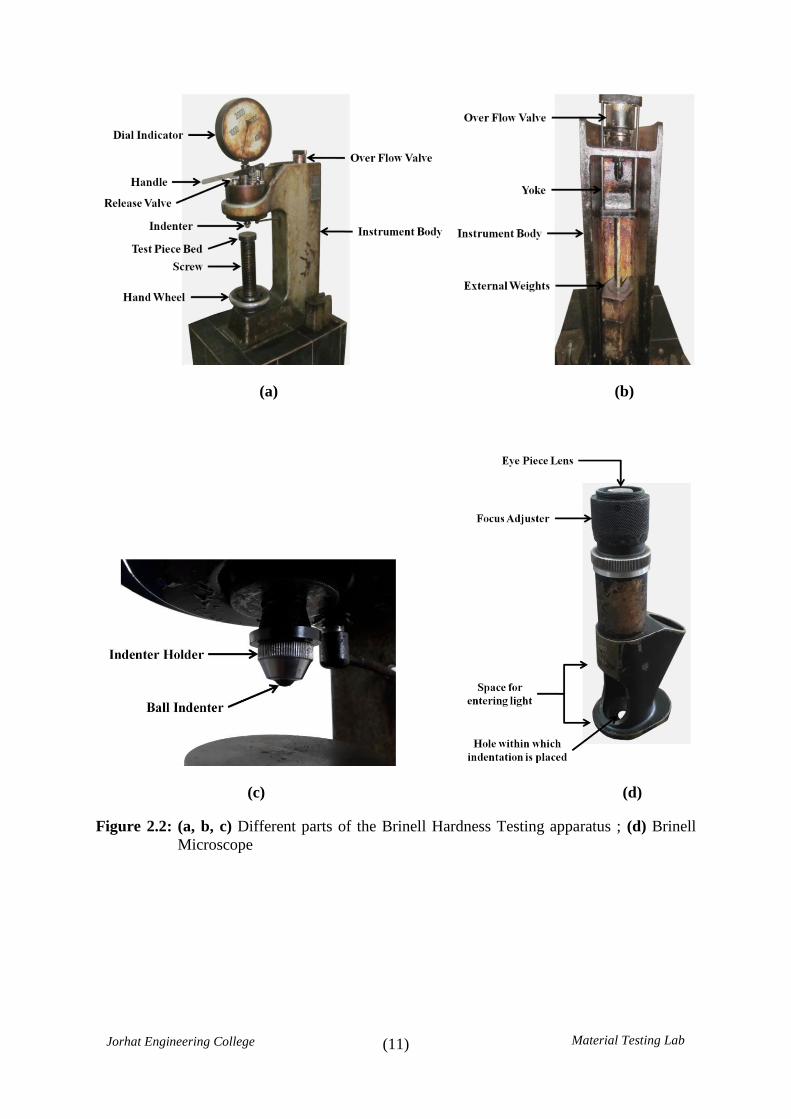
1. Brinell Hardness Tester [fig. 2.2 (a, b, c)]
Manufactured by Zaklady Automatyki Przemyslowej,
Poland
2. External Weights: 3000 kg for hard material, 1500 kg for
intermediate material, and 500 kg for soft material. Refer
Table 2.1 for more details.
3. Steel Ball Indenter of 10 mm diameter [fig. 2.2 (c)]
4. Brinell Microscope [fig. 2.2 (d)]
Manufactured by PZO Warszawa, Poland
THEORY:
The hardness of a material is its resistance to penetration under a localized
pressure or resistance to abrasion. Hardness test provides an accurate, rapid and
economical way of determining the resistance of material to deformation.
In this test, a Tungsten Carbide steel ball indenter of diameter D is pressed
against the surface of the test piece by a gradually applied load P, and this force is
maintained for a definite amount of time. The impression on the test piece so obtained
is measured using an optical microscope and the required Brinell Hardness Number
(BHN) or Brinell Hardness (HB) is calculated using the following relation:
𝐁𝐇𝐍 𝐨𝐫 𝐇𝐁 =𝐀𝐩𝐩𝐥𝐢𝐞𝐝 𝐭𝐞𝐬𝐭 𝐟𝐨𝐫𝐜𝐞 𝐢𝐧 𝐤𝐠𝐟
𝐀𝐫𝐞𝐚 𝐨𝐟 𝐢𝐦𝐩𝐫𝐞𝐬𝐬𝐢𝐨𝐧 𝐢𝐧 𝐦𝐦𝟐=
𝑷
𝑨
Where,
𝑃 = Applied Test Force in kgf.
𝐴 = Indented area = 𝜋 𝐷 2 𝐷 − 𝐷2 − 𝑑2 1 2

(8)
Jorhat Engineering College Material Testing Lab
𝐷 = Diameter of steel ball indenter = 10 mm
𝑑 = Diameter of impression on the test piece
The BHN is expressed in kg/mm2. For obtaining good results, the steel ball indenter
used in this test should be well polished and free from any surface defects.
PRECAUTIONS:
The thickness of the test piece should be at least 8-10 times the depth of
indentation. Visible deformation at the back of the test piece can indicate that
the test piece is too thin.
The test should be carried out at ambient temperature within the limits of 10℃
to 35℃. However, because temperature variations may affect the results, hence
for better results, the test can be carried under controlled environment.
The test surface should be smooth and even, free from oxide scale, foreign
matters and, in particular, completely free from lubricants.
Brinell Hardness test is not recommended for materials above 650 HBW
10/3000.
PROCEDURE:
1. Place the test piece on the test piece Bed of the apparatus.
2. Raise the Bed by rotating the Hand Wheel in clockwise direction till the initial
contact between the surface of the test piece and the indenter is made.
3. Place suitable External Weights on the Yoke and close the Release Valve. The
amount of external weights attached corresponds to the test force that would be
applied on the test piece.
4. Start pumping the hydraulic fluid by moving the Handle up-and-down to
gradually increase the test force on the test piece, till the fluid overflows
through the Overflow Valve. Overflow gives an indication that the maximum
amount of test force has been applied on the test piece.
5. Keep the test force in application for about 15 seconds (dwell time).
6. Now, open the release valve to release the test force.

(9)
Jorhat Engineering College Material Testing Lab
7. Lower the Bed and collect the test piece.
8. Measure the diameter of the impression by using the Brinell Microscope.
Hence, calculate the area of impression and the required Brinell Hardness
Number (BHN).
OBSERVATION TABLE – 1
Sl.
No. Specimen
Diameter of
steel ball
Indenter 𝑫 𝒎𝒎
Diameter of
Impression
𝒅 𝒎𝒎
Area of
Impression
𝑨 𝒎𝒎𝟐
BHN Average
BHN
1
Flat Mild Steel
Plate
2
3
OBSERVATION TABLE – 2
Sl.
No. Specimen
Diameter of
steel ball
Indenter 𝑫 𝒎𝒎
Diameter of
Impression
𝒅 𝒎𝒎
Area of
Impression
𝑨 𝒎𝒎𝟐
BHN Average
BHN
1
Flat High
Carbon
Steel Plate
2
3
RESULT:
1. The hardness of the mild steel test piece is found to be :
2. The hardness of the high carbon steel test piece is found to be :

(10)
Jorhat Engineering College Material Testing Lab
Figure 2.1: Writing a particular Result after test [as per ISO 6506-1:2014(E)]
Hardness symbol HBW should be used if a Tungsten Carbide Ball Indenter is
used, where W is the chemical symbol for Tungsten. Otherwise, if a Hardened Steel
Ball indenter is used, the hardness symbol HBS should be used, where S denotes
Hardened Steel.
(11)
Jorhat Engineering College Material Testing Lab
(a) (b)
(c) (d)
Figure 2.2: (a, b, c) Different parts of the Brinell Hardness Testing apparatus ; (d) Brinell
Microscope

(12)
Jorhat Engineering College Material Testing Lab
Table 2.1: Test Forces for different hardness conditions and hardness range
Hardness
Symbol
Ball
Diameter
(D)
(mm)
Test force
value (F)
(kgf)
Force-diameter
index
(F/D2)
Recommended
Hardness Range
(HBW)
HBW 10/3000 10 3000 30 95.5 to 650
HBW 10/1500 10 1500 15 47.7 to 327
HBW 10/1000 10 1000 10 31.8 to 218
HBW 10/500 10 500 5 15.9 to 109
HBW 10/250 10 250 2.5 7.96 to 54.5
HBW 10/125 10 125 1.25 3.98 to 27.2
HBW 10/100 10 100 1 3.18 to 21.8
HBW 5/750 5 750 30 95.5 to 650
HBW 5/250 5 250 10 31.8 to 218
HBW 5/125 5 125 5 15.9 to 109
HBW 5/62.5 5 62 2.5 7.96 to 54.5
HBW 5/31.25 5 31.25 1.25 3.98 to 27.2
HBW 5/25 5 25 1 3.18 to 21.8
HBW 2.5/187.5 2.5 188 30 95.5 to 650
HBW 2.5/62.5 2.5 62 10 31.8 to 218
HBW 2.5/31.25 2.5 31 5 15.9 to 109
HBW 2.5/15.625 2.5 16 2.5 7.96 to 54.5
HBW 2.5/7.8125 2.5 7.8125 1.25 3.98 to 27.2
HBW 2.5/6.25 2.5 6 1 3.18 to 21.8
HBW 1/30 1 30 30 95.5 to 650
HBW 1/10 1 10 10 31.8 to 218
HBW 1/5 1 5 5 15.9 to 109
HBW 1/2.5 1 3 2.5 7.96 to 54.5
HBW 1/1.25 1 1.25 1.25 3.98 to 27.2
HBW 1/1 1 1 1 3.18 to 21.8
REFERENCES:
ISO 6506-1:2014(E) document.
ASTM E10-15 and ASTM E10-01 document.

(13)
Jorhat Engineering College Material Testing Lab
Exp. No. 2 Title: To determine hardness of a mild steel and high carbon
steel specimen.
Name of Student:
Roll No.:
Date of Experiment:
Date of Submission:
Signature of Teacher SEAL
with Date of Check

(14)
Jorhat Engineering College Material Testing Lab
Experiment No. 3
TITLE: Charpy Pendulum Impact Test.
OBJECTIVE:
To determine impact resistance of an assigned specimen in
the form of a notched bar flexure specimen.
APPARATUS REQUIRED:
Charpy Pendulum Impact test apparatus (Fig. 3.3)
V-notched bar. (Fig. 3.2)
THEORY:
A notched bar of definite geometry is broken with the single blow from a
swinging pendulum, dropped from a definite height, and the energy absorbed during the
impact is determined. This absorbed energy during the impact is the impact resistance
of the test piece.
The pendulum of mass 𝑚 𝑘𝑔 is raise to a definite height ℎ1 and then dropped
freely to swing. The striker edge of the pendulum then hits the test piece at a point just
opposite to the notch, breaks it into two pieces, and swings freely to a height ℎ2 on the
other side. Energy absorbed during the process is the energy used in breaking the
specimen, and that is equal to 𝑚𝑔 ℎ1 − ℎ2 .
PROCEDURE:
1. Place the specimen on the supports and against the anvils as shown in Fig. 3.1. The
notch should be on the side of the specimen away from the striking edge of the
pendulum and directly in line with it.
2. Raise the pendulum to a certain height ℎ1 and hold it. Record the first dial reading and
find the initial Potential Energy 𝑃𝐸 = 𝑚𝑔ℎ stored in the pendulum at this height.
The dial reading directly gives the value of 𝑚ℎ. Multiply this value with 𝑔 to get the
value of 𝑃𝐸.
3. Then release the pendulum to fall freely and rapture the specimen. The pendulum will
then rise to a maximum height ℎ2 on the other side. Record the second dial reading
and find the final 𝑃𝐸 for the pendulum at that height.

(15)
Jorhat Engineering College Material Testing Lab
4. Now calculate the energy lost during the impact. This is the required impact resistance
of the test specimen.
OBSERVATION:
Specimen
Initial PE of
the Pendulum
at height
𝒉𝟏 = 𝑿𝟏 Joule
Final PE of
the Pendulum
at height
𝒉𝟐 = 𝑿𝟐 Joule
Energy absorbed
during impact
𝑿𝟏 − 𝑿𝟐
(Joule)
Average
(Joule)
Mild Steel Bar
RESULT:
The impact resistance of the given test specimen is found to be : ……………..… 𝑲𝑽𝟐
Here, 𝐾𝑉 is used to denote the impact resistance of the test piece. Letter 𝑽 is used for
V-notch and 𝑼 for U-notch; and the subscript 2 in 𝐾𝑉2 denotes the striker radius in
𝑚𝑚.
Figure 3.1: Placement of the test piece on apparatus supports

(16)
Jorhat Engineering College Material Testing Lab
Figure 3.2: Geometry of the V-notched bar [as per ISO 148-1:2009(E)]
Table 3.1: Tolerances on specified test piece dimensions [as per ISO 148-1:2009(E)]
Designation Symbol
used
Nominal
Dimension
Machining
Tolerance
Length 𝑙 55 𝑚𝑚 ±0.60 𝑚𝑚
Height ℎ 10 𝑚𝑚 ±0.075 𝑚𝑚
Width
(for standard test piece) 𝑤 10 𝑚𝑚 ±0.11 𝑚𝑚
Angle of notch 𝜃 45° ±2°
Height below notch
(height of test piece minus depth of notch) 𝑥 8 𝑚𝑚 ±0.075 𝑚𝑚
Radius of curvature at base of notch 𝑅 0.25 𝑚𝑚 ±0.025 𝑚𝑚
Depth of notch 𝑧 2 𝑚𝑚 −
Distance of plane of symmetry of notch from ends of
test piece 𝑦 27.5 𝑚𝑚 ±0.42 𝑚𝑚
Angle between adjacent longitudinal faces of test
piece
𝛼 90° ±2°

(17)
Jorhat Engineering College Material Testing Lab
Figure 3.3: Parts of the Charpy Impact Test apparatus
(18)
Jorhat Engineering College Material Testing Lab
REFERENCE:
ISO 148-1:2009(E) document.
Exp. No. 3 Title: Charpy Pendulum Impact Test.
Name of Student:
Roll No.:
Date of Experiment:
Date of Submission:
Signature of Teacher SEAL
with Date of Check

(19)
Jorhat Engineering College Material Testing Lab
Experiment No. 4
TITLE: Compressive Stress Test.
OBJECTIVE:
To determine the compressive Strength of a given specimen.
APPARATUS:
Compressive Test apparatus
In this machine head is actuated
hydraulically and a hydraulic gauge
indicates the load. Oil is pumped from the
supply tank through control valve into the
cylinder. The piston at bottom of the
cylinder is forced upward lifting the table.
THEORY:
Compressive Stress =Compressive load
Cross − sectional Area
PROCEDURE:
1. Determine the average surface area of the specimen.
2. Place the specimen on the bottom plate at the mid position.
3. Lower the upper plate by rotating the hand wheel and fix the test specimen.
4. Select suitable speed of the load by rotating the Fluid Flow Regulator.
5. Load the machine until the specimen fails.
6. Record the compressive load from the hydraulic gauge.

(20)
Jorhat Engineering College Material Testing Lab
OBSERVATION TABLE:
Specimen:
Sl.
No.
Length
𝒎𝒎 Breadth
𝒎𝒎
Cross-
sectional
Area
𝒎𝒎𝟐
Average Cross-
sectional Area
𝒎𝒎𝟐
Compressive
Load
𝒌𝑵
Compressive
Stress
𝒌𝑵 𝒎𝒎𝟐
1
2
3

(21)
Jorhat Engineering College Material Testing Lab
Figure 4.1: Labeled pictures of the machines

(22)
Jorhat Engineering College Material Testing Lab
Exp. No. 4 Title: Compressive Stress Test.
Name of Student:
Roll No.:
Date of Experiment:
Date of Submission:
Signature of Teacher SEAL
with Date of Check

(23)
Jorhat Engineering College Material Testing Lab
Experiment No. 5
TITLE: Torsion Test.
OBJECTIVE:
To determine Modulus of Rigidity 𝐶 , Breaking Torque 𝑇 and Ultimate Shear Stress
𝜏 of a mild steel specimen by conducting Torsion Test.
THEORY:
When a shaft is subjected to equal and opposite twisting
moments or torques, the shaft is said to be in torsion. To
understand this better, let us consider an axisymmetrical shaft
AB of length L with one end fixed and the other end free, as
shown in Fig. 5.1 (a). To visualize the deformation, draw
longitudinal lines and circles perpendicular to the longitudinal
lines before applying the torque. After applying the torque at
the free end, deformation will take place and the longitudinal
lines will form helixes as the circles rotate in their own planes.
This is shown in Fig. 5.1 (b).
Figure 5.1(a) Figure 5.1(b)
If the space between the circular lines is assumed to represent a circular layer of
the shaft, then the shaft can be visualized to be composed of a number of such circular
layers. When torque is applied, each circular layer will rotate against its adjacent layer,
and in this process it will impart a tangential force on its adjacent layer. Thus the
adjacent layer will develop Shear Stress to maintain its shape and size. This process
continues from the initial layer at the free end till the last layer at the fixed end and the

(24)
Jorhat Engineering College Material Testing Lab
intensity of shear force as well as shear stress decreases as we move away from the
point of application of the torque.
Hence, due to applied torque, the material of the shaft will develop shear stress.
When the applied torque exceeds the internal stress resultants, shear strain will be
induced in the shaft. Also, the value of shear stress increases as radius increases. i.e.
shear stress is zero at the longitudinal axis, increases gradually and reaches to a
maximum value at the outer surface.
The following Torsion Equation can be derived for an axisymmetrical shaft:
𝑻
𝑱=
𝝉
𝑹=
𝑪𝜽
𝑳
Here,
𝑇 = Maximum Torque / Breaking Torque (N-m) ; [ 1 in.lbs = 0.112984825 N-m ]
=𝜋
16𝜏𝐷3 ; 𝐷 = Diameter of the shaft mm
𝑅 = Radius of the shaft (mm)
𝐽 = Polar Moment of Inertia mm4 =𝜋𝑑4
32
𝜏 = Maximum shear stress at the outer surface at a radial distance 𝑅 𝑁 𝑚𝑚2
𝐶 = Modulus of rigidity for the material of the shaft 𝑁 𝑚𝑚2
=Shear stress
Shear strain=
𝜏
𝜑
𝜃 = Angle of twist (𝑟𝑎𝑑𝑖𝑎𝑛)
𝐿 = Length of the shaft (𝑚𝑚)
PRECAUTIONS:
The test piece should be as straight as possible along the gauge length.
The grips of the test piece should not rotate while twisting the test piece.
The test should be carried out at an ambient temperature of 10℃ to 35℃ .
(25)
Jorhat Engineering College Material Testing Lab
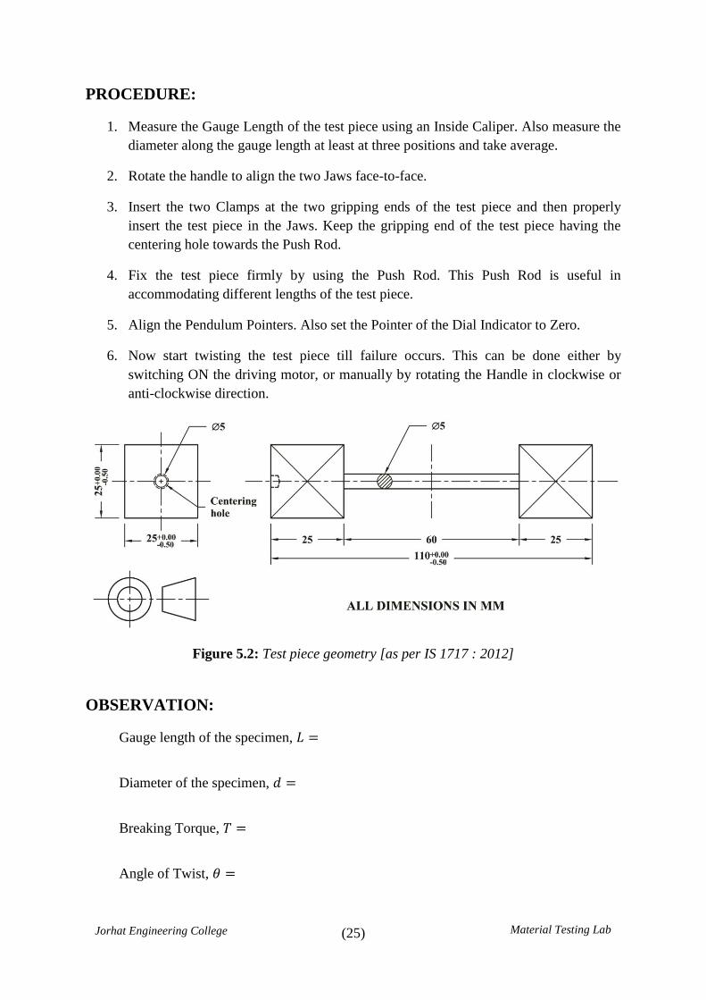
PROCEDURE:
1. Measure the Gauge Length of the test piece using an Inside Caliper. Also measure the
diameter along the gauge length at least at three positions and take average.
2. Rotate the handle to align the two Jaws face-to-face.
3. Insert the two Clamps at the two gripping ends of the test piece and then properly
insert the test piece in the Jaws. Keep the gripping end of the test piece having the
centering hole towards the Push Rod.
4. Fix the test piece firmly by using the Push Rod. This Push Rod is useful in
accommodating different lengths of the test piece.
5. Align the Pendulum Pointers. Also set the Pointer of the Dial Indicator to Zero.
6. Now start twisting the test piece till failure occurs. This can be done either by
switching ON the driving motor, or manually by rotating the Handle in clockwise or
anti-clockwise direction.
Figure 5.2: Test piece geometry [as per IS 1717 : 2012]
OBSERVATION:
Gauge length of the specimen, 𝐿 =
Diameter of the specimen, 𝑑 =
Breaking Torque, 𝑇 =
Angle of Twist, 𝜃 =
(26)
Jorhat Engineering College Material Testing Lab
CALCULATION:
Polar Moment of Inertia (J)
Maximum / Ultimate Shear Stress 𝝉
Modulus of Rigidity (C)
(27)
Jorhat Engineering College Material Testing Lab
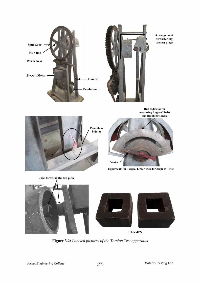
Figure 5.2: Labeled pictures of the Torsion Test apparatus
(28)
Jorhat Engineering College Material Testing Lab
REFERENCE:
ISO 7800 : 2003 document.
Exp. No. 5
Title: To determine Modulus of Rigidity (𝐶) , Breaking Torque
𝑇 and Ultimate Shear Stress 𝜏 of a mild steel
specimen by conducting Torsion Test.
Name of Student:
Roll No.:
Date of Experiment:
Date of Submission:
Signature of Teacher SEAL
with Date of Check

(29)
Jorhat Engineering College Material Testing Lab
Experiment No. 6
TITLE: Tension Test.
OBJECTIVE:
To determine the following parameters of
the given specimen:
1. Elongation
2. Maximum stress
3. Breaking stress
4. % age of reduction of Area
THEORY:
Refer to the following Stress – Strain diagram for ductile material.
APPARATUS:
1. Universal Testing Machine
(30)
Jorhat Engineering College Material Testing Lab
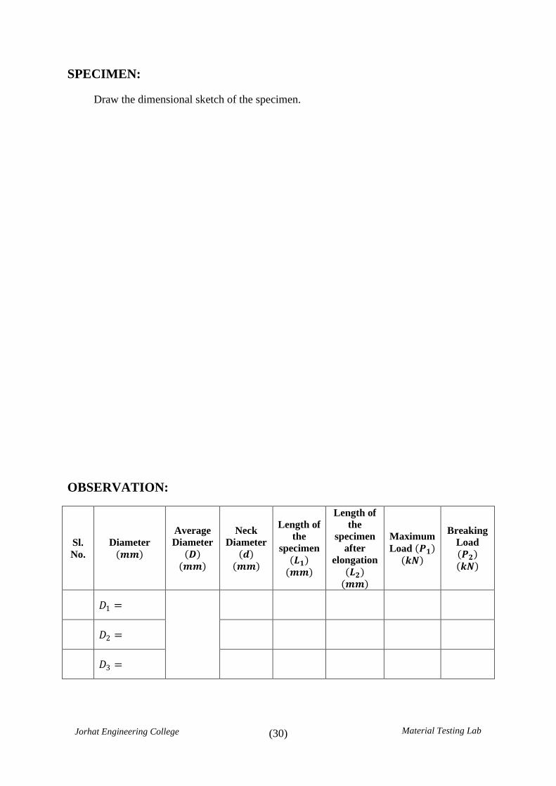
SPECIMEN:
Draw the dimensional sketch of the specimen.
OBSERVATION:
Sl.
No.
Diameter
𝒎𝒎
Average
Diameter
𝑫 𝒎𝒎
Neck
Diameter
𝒅 𝒎𝒎
Length of
the
specimen
𝑳𝟏 𝒎𝒎
Length of
the
specimen
after
elongation
𝑳𝟐 𝒎𝒎
Maximum
Load 𝑷𝟏 𝒌𝑵
Breaking
Load
𝑷𝟐 𝒌𝑵
𝐷1 =
𝐷2 =
𝐷3 =
(31)
Jorhat Engineering College Material Testing Lab
RESULTS:
1. Elongation = 𝐿2 − 𝐿1 =
2. Maximum stress 𝑃1 𝐷 =
3. Breaking stress = 𝑃2 𝐷 =
Therefore, % Reduction of Area = 𝜋 4 𝐷2 − 𝑑2 =
Exp. No. 6 Title: Tension Test.
Name of Student:
Roll No.:
Date of Experiment:
Date of Submission:
Signature of Teacher SEAL
with Date of Check
Related Documents