0 15.08.2019 Final issue GEN TJO SEJ Rev. Publish date Description Made by Checked by Project appro. Client appro. Client Contractor Contract no.: 18/91094 Document name: Preferred solution, K12 – Appendix O Material technology and steel in marine environment Document no.: SBJ-33-C5-AMC-04-RE-115 Rev.: 0 Pages: 22 Ferry free E39 –Fjord crossings Bjørnafjorden 304624

Welcome message from author
This document is posted to help you gain knowledge. Please leave a comment to let me know what you think about it! Share it to your friends and learn new things together.
Transcript

0 15.08.2019 Final issue GEN TJO SEJ
Rev. Publish
date
Description Made by Checked
by
Project
appro.
Client
appro.
Client
Contractor Contract no.:
18/91094
Document name:
Preferred solution, K12 – Appendix O
Material technology and steel in marine environment
Document no.:
SBJ-33-C5-AMC-04-RE-115
Rev.:
0
Pages:
22
Ferry free E39 –Fjord crossings Bjørnafjorden 304624


CONCEPT DEVELOPMENT, FLOATING BRIDGE E39 BJØRNAFJORDEN
Preferred solution, K12
Appendix O – Material technology and steel in marine environment
CLIENT
Statens vegvesen
DATE: / REVISION: 15.08.2019 / 0 DOCUMENT CODE: SBJ‐33‐C5‐AMC‐04‐RE‐115

SBJ-33-C5-AMC-04-RE-115 15.08.2019 / 0 Page 2 of 22

0 15.08.2019 Final issue Guri E. Nustad Tor Johansen S. E. Jakobsen
REV. DATE DESCRIPTION PREPARED BY CHECKED BY APPROVED BY
REPORT
PROJECT Concept development, floating bridge
E39 Bjørnafjorden DOCUMENT CODE SBJ-33-C5-AMC-04-RE-115
SUBJECT Appendix O – Material technology and steel in marine environment – K12
ACCESSIBILITY Restricted
CLIENT Statens vegvesen PROJECT MANAGER Svein Erik Jakobsen
CONTACT Øyvind Kongsvik Nedrebø PREPARED BY
Guri Elisabeth Nustad Tor Johansen
Ane Kristin Haraldsen
RESPONSIBLE UNIT AMC
SUMMARY
The bridge design life is 100 years and this document discusses material selection and means of providing corrosion
protection to limit the need for future inspections, maintenance, and replacements. The recommended solutions are
summarised in the table below.
The most severe exposure conditions are in the splash zone and in this area carbon steel will be replaced by a
corrosion resistant alloy, 25Cr DSS. Welding of carbon steel to 25Cr DSS is fully manageable provided properly
qualified procedures and suitable materials are used.
High level cathodic protection (CP) calculations have been performed. The anode weight requirements vary
dependent on the selected CP design life and extent of coating on the 25Cr DSS plates. Detailed calculations should
be performed in next phase.
Corrosion allowances (CA) for the mooring chains have been evaluated based on standards and requirements
included in the SVV design basis. Since the top chain is situated below the splash zone, the same CA as for the bottom
chain is proposed (0.2 mm/year).
Recommendations for further work is included in a separate section at the end of the document.
Bridge section Generic material selection Proposed corrosion protection
Upper section: Underside of road structure, columns and pontoon above splash zone
Carbon steel SVV system 2
Pontoon, splash zone and submerged section
Carbon steel with solid 25 Cr duplex stainless steel in splash zone
NORSOK System 7B + aluminium based sacrificial anodes
Ballast water tank, active tank Carbon steel NORSOK system 7B + zinc based sacrificial anodes
Ballast water tank, passive tank Carbon steel NORSOK system 1
Empty sections / voids in the pontoon with active dehumidification
Carbon steel NORSOK system 3G
Empty sections / voids in the pontoon without active dehumidification
Carbon steel NORSOK system 1

Concept development, floating bridge E39 Bjørnafjorden
Appendix O – Material technology and steel in marine environment TABLE OF CONTENTS
SBJ-33-C5-AMC-04-RE-115 15.08.2019 / 0 Page 4 of 22
TABLE OF CONTENTS
1 Scope .................................................................................................................................................................................... 5
2 Abbreviations and Explanation ............................................................................................................................................. 5
3 General ................................................................................................................................................................................. 6 3.1 Methods of providing corrosion protection.......................................................................................................................... 6 3.2 Material Requirements – Structural Steel ............................................................................................................................ 7
3.2.1 Carbon Steel ............................................................................................................................................................. 7 3.2.2 25Cr DSS ................................................................................................................................................................... 7 3.2.3 Bolting ...................................................................................................................................................................... 8
4 Fabrication............................................................................................................................................................................ 9 4.1 Welding of 25Cr DSS and carbon steel .................................................................................................................................. 9
5 Upper sections .................................................................................................................................................................... 10 5.1 Voids and empty compartments......................................................................................................................................... 11 5.2 Outfitting structures ........................................................................................................................................................... 11
6 Splash Zone ........................................................................................................................................................................ 12 6.1 Material selection ............................................................................................................................................................... 12
7 Submerged structures ......................................................................................................................................................... 15 7.1 External surfaces ................................................................................................................................................................. 15
7.1.1 External surfaces submerged in mud ..................................................................................................................... 15 7.2 Ballast water tanks .............................................................................................................................................................. 15 7.3 Cathodic protection ............................................................................................................................................................ 16
8 Mooring System .................................................................................................................................................................. 19 8.1 General ............................................................................................................................................................................... 19 8.2 Corrosion protection ........................................................................................................................................................... 19
9 Design against hydrogen induced stress cracking ................................................................................................................ 20
10 Recommendations for further work .................................................................................................................................... 21 10.1 Material requirements and fabrication .............................................................................................................................. 21 10.2 Corrosion protection ........................................................................................................................................................... 21
11 List of references ................................................................................................................................................................ 22

Concept development, floating bridge E39 Bjørnafjorden
Appendix O – Material technology and steel in marine environment – K12 1 Scope
SBJ-33-C5-AMC-04-RE-115 15.08.2019 / 0 Page 5 of 22
1 Scope
This document is a further development of the material selection and means of providing corrosion
protection proposed in the phase 3 concept study for Bjørnafjorden floating bridge.
The bridge design life is 100 years and the scope related to material selection, and corrosion
protection is to propose solutions that will limit the need for future inspections, maintenance, repairs
and replacements.
Different methods for protection are required, depending on the exposure to the elements. The
exposure conditions for the following zones are discussed in separate sections of this document:
The upper external section consisting of the pontoon section above splash zone and the
above bridge structure
The splash zone of the pontoons defined as a height of 4 m between the upper and
submerged parts of the construction
The submerged external sections of the pontoons
The ballast water tanks inside the pontoons
Voids/empty sections
In the earlier study, duplex stainless steel with 25 %Cr (25Cr DSS) was recommended as a suitable
corrosion resistant alloy (CRA) for the splash zone. In this phase, only the option with solid 25Cr DSS
as replacement for carbon steel in the splash zone is further evaluated.
2 Abbreviations and Explanation
25Cr DSS Duplex Stainless Steel with 25 % Cr
22Cr DSS Duplex Stainless Steel with 22 % Cr
SS 316 Austenitic Stainless Steel type AISI 316
CP Cathodic Protection
CRA Corrosion Resistant Alloy
DFT Dry Film Thickness
FMECA Failure Mode, Effect and Criticality Analysis
GRP Glass Fibre Reinforced Plastic
HAZ Heat Affected Zone
HISC Hydrogen Induced Stress Cracking
MIC Micro Biological Corrosion
RH Relative Humidity
SVV Statens Vegvesen
TSA Thermally Sprayed Aluminium
TSZ Thermally Sprayed Zinc

Concept development, floating bridge E39 Bjørnafjorden
Appendix O – Material technology and steel in marine environment – K12 3 General
SBJ-33-C5-AMC-04-RE-115 15.08.2019 / 0 Page 6 of 22
3 General
3.1 Methods of providing corrosion protection
In principle, the following methods are available to avoid corrosion:
Select corrosion resistant materials
Reduce corrosivity of the environment by e.g. dehumidification
Introduce a protective barrier against the corrosive environment by e.g. coating application
Make the steel immune to the corrosive environment by cathodic protection (CP)
Selecting corrosion resistant materials is theoretically an option for all parts of the bridge, but is cost
effective only for parts exposed to very corrosive conditions combined with poor access for later
maintenance and repairs. Herein, this option is therefore only evaluated for the splash zone.
For voids and empty compartments, corrosion can be limited by reducing the relative humidity (RH).
Below 60% RH corrosivity is strongly reduced, below 40%RH corrosion will not occur.
A corrosion barrier in the form of a coating system is a common way of protecting steel structures
and is recommended for carbon steel parts exposed to marine environment. For carbon steel
submerged in seawater coating combined with cathodic protection is recommended.
Selection of coating systems shall be based on an expectancy to provide corrosion protection for minimum 20 to 30 years prior to first maintenance. First maintenance should be carried out when coating degradation reaches Ri3, i.e. European rust scale Re3 that equals 1 % of the surface area being affected as advised in ISO 4628 /Ref. 1/ and ISO 12944 /Ref. 2/ Performing the first repair at this stage is generally regarded as cost effective regardless of type of coating system.
The following parameters are of utmost importance to achieve durable corrosion protection:
A coating friendly design is required. This means a design with slope to avoid water trapping,
limiting corners and edges, avoiding narrow gaps, etc. To ensure that such points are captured
and minimised, a design review meeting should be arranged prior to finalising the bridge
design.
Ensure proper surface preparation and coating application. This is related to:
o Rounding of edges;
o Surface cleanliness;
o Surface roughness;
o Remaining chloride content on the steel surface;
o Conditions during application: temperature, dew point, relative humidity;
o Workmanship: Operator knowledge and experience, equipment and QC inspection.
Focus on these parameters represents the key to success. Hence, prior to selecting a paint shop, their
facilities, knowledge and experience need to be verified.
It should be noted that the cost of the coating products is low compared to the total application costs
when including surface preparation, application, and quality control. Hence, it is recommended that
the actual coating products are selected based on technical suitability and pre-qualification only.

Concept development, floating bridge E39 Bjørnafjorden
Appendix O – Material technology and steel in marine environment – K12 3 General
SBJ-33-C5-AMC-04-RE-115 15.08.2019 / 0 Page 7 of 22
CP is required for carbon steel structures submerged in seawater. CP can be provided by installation
of sacrificial anodes or by application of an impressed current cathodic protection system. Herein, CP
by sacrificial anodes is recommended both externally and internally.
Coating system references are based on NORSOK M-501 /Ref. 15/.
3.2 Material Requirements – Structural Steel
Håndbok R762 Prosesskode 2, prosess 85, /Ref. 3/ specifies requirements to structural materials for
bridges. Steel structures shall be CE-marked in accordance with NS-EN 1090, /Ref. 4/and as such,
steel materials according to NS-EN 1090-2 /Ref. 24/ and R762 shall be used.
For 25Cr DSS materials, proposed material requirements are included herein.
3.2.1 Carbon Steel
Structural steel shall be delivered according to the standards and additional requirements specified
by R762, Section 85.1.
The proposed design is based on use of plates, sections made from plate (welded girders and
tubulars), and bulb profiles in grade S420.
For grade S420, SVV specifies delivery condition normalized (N / NL) or TMCP (M / ML). Normalized
steel according to EN 10025-3 allows relatively high content of vanadium. This may increase risk of
precipitates (vanadium carbonitrides), e.g. during stress relieving / annealing. It is proposed to
evaluate whether TCMP (M / ML) should be specified as the only alternative in the next phase. See
section 10.1.
3.2.2 25Cr DSS
It is proposed to replace carbon steel with 25Cr DSS plates in the splash zone of the pontoons.
Stringers may remain in carbon steel.
Structural design of stainless steels will be based on EN 1993-1-4 /Ref. 5/. This standard refers to the
EN 10088-series for material requirements. The technical requirements for sourcing 25Cr DSS plates
should therefore be based on EN 10088-2 /Ref. 6/, alternatively EN 10028-7 /Ref. 7/ which is typically
used for pressure vessels.
In the oil and gas sector, NORSOK M-650 qualified manufacturers are normally required for special
materials, including 25Cr DSS. However, for structural purposes, such as on the Bjørnafjorden Bridge,
it is proposed not to include this as an absolute requirement.
Further, to save cost, requirements additional to the chosen material standard should be kept to a
minimum. Typical additional or clarifying requirements to ensure quality materials would, however,
typically include requirements to:
steel making process,
chemical composition
heat treatment,
impact testing (typically -46degC, 46/35 J),
corrosion testing (typically ASTM G48 method A, 50 °C /Ref. 9/)

Concept development, floating bridge E39 Bjørnafjorden
Appendix O – Material technology and steel in marine environment – K12 3 General
SBJ-33-C5-AMC-04-RE-115 15.08.2019 / 0 Page 8 of 22
It is recommended to establish a Material Data Sheet(s) (MDS) for 25Cr DSS materials based on
NORSOK M-630 /Ref. 10/. Summarizing the material requirements in such a format facilitates
procurement, reduces the risk of mistakes, and is transparent and user friendly.
If the above initiatives are found not to decrease cost, NORSOK M-630 MDS D55 may be used as is,
including the NORSOK M-650 qualification requirement. See section 10.1.
3.2.3 Bolting
Requirements to bolting materials are specified in R762, Section 85.13. No critical bolted
connections have been identified for the Bjørnafjorden bridge. Therefore, no particular evaluations
are deemed necessary in this phase.
It is recommended that stainless steel bolting (type A4 / 316 SS) is used irrespective of bolt size for
fixing stainless steel equipment and outfitting.

Concept development, floating bridge E39 Bjørnafjorden
Appendix O – Material technology and steel in marine environment – K12 4 Fabrication
SBJ-33-C5-AMC-04-RE-115 15.08.2019 / 0 Page 9 of 22
4 Fabrication
Håndbok R762 Prosesskode 2, prosess 85, refers to NS-EN 1090-2 for fabrication of structures. In
addition to the requirements in R762, fabrication shall be based on execution class 3 (EXC3).
4.1 Welding of 25Cr DSS and carbon steel
Welding of dissimilar welds between 25Cr DSS and carbon steel shall be according to NS-EN 1090 and
NS-EN 1993-1-4. In a dissimilar metal weld both parent metals (A and B), and the welding
consumable must be considered to produce sound joints. Risk of martensite formation is primarily
governed by carbon content of the base material (carbon steel side), dilution ratio, and the selected
welding consumable.
Constitution (Schaeffler) diagrams can be used to predict the composition of the weld metal. A
typical example showing the resulting microstructure of the weld on the carbon steel side (i.e. mix of
a typical consumable (309) and carbon steel, identified by round marker) is given below:
As can be seen from the diagram, a carbon steel dilution of 25% results in a weld metal
microstructure consisting of austenite and ferrite. Martensite is avoided. As the position of 25Cr SDSS
in the diagram is to the right of the typical consumable (309), a dilution/mix with 25Cr SDSS parent
material will not increase the risk of martensite formation. Risk of martensite formation is further
reduced by specifying carbon steel with a limit on carbon content (typically < 0.18%). Such a
limitation is not uncommon and is not believed to increase cost.
Welding of carbon steel to corrosion resistant alloys (CRA) is an established practice and various
welding consumables have been used over the years. 309LMo is commonly used for welding carbon
steel to CRAs (incl. 25Cr SDSS). If welds of matching strength are required, type 2509 weld
consumable may be considered.
Based on the above, Contractor considers welding carbon steel to 25Cr SDSS to be fully manageable
provided properly qualified procedures are used and restrictions on carbon content is specified.

Concept development, floating bridge E39 Bjørnafjorden
Appendix O – Material technology and steel in marine environment – K12 5 Upper sections
SBJ-33-C5-AMC-04-RE-115 15.08.2019 / 0 Page 10 of 22
5 Upper sections
The upper sections are to be understood as the underside of road structure, columns and pontoon
above splash zone. In these sections, access allows for regular inspection and maintenance. Still, a
high quality coating system is recommended to limit the need for future maintenance. Based on the
experience from Statens Vegvesen (SVV) their system 2, Thermally Sprayed Zinc (TSZ) covered with a
tie coat and a 3- coat system has proven very durable as outlined in a presentation at
Teknologidagene in 2015 /Ref. 13/. This is in line with experience from the North Sea although the
major operator in the Norwegian sector specifies Thermally Sprayed Aluminium (TSA, e.g. NORSOK
system 2A) as the default system for structures and pressure retaining equipment that are highly
exposed and/or hard to maintain /Ref. 14/ and /Ref. 15/. Both TSA and SVV system 2 are active
systems that will provide local cathodic protection in case of coating damage.
The high quality coating systems discussed in the previous phase have been evaluated further. Their
pros and cons are summarised in Table 5-1 below along with a recommendation. In addition, a
corrosion allowance may be added depending on maintenance philosophy. See section 10.2.
Table 5-1 Candidate coating systems for upper external bridge sections
Coating system
Generic products
Good experience reported from
Pros Cons Recommendation
High build glass flake
High build glass flake epoxy or polyester
Splash zone, underside of platform decks, and platform substructures (jackets) where access for maintenance is poor.
Its high DFT provides a very robust barrier both against corrosion and mechanical wear.
Passive system - no protection of any exposed steel.
Poor UV properties, will need a top coat to maintain gloss and colour.
Not recommended for further evaluation
TSA Metallic aluminium and epoxy sealer
Splash zone, underside of platform decks, topside structures and equipment where access for maintenance is poor or exposure temperature is high.
Active system (TSA).
By increasing the DFT service life can be extended. Robust barrier both against corrosion and mechanical wear.
Can only be over coated with a sealer. Surface will be greyish with a matt appearance. Removal of dirt may be challenging. Difficult to combine with other coating systems. Application is time consuming, noisy and dusty. Application with spray gun only. Expensive.
Can be evaluated since upper sections may be matt metallic, i.e. no specific colour requirement.
SVV system 2
Metallic zinc with sealer, two layers epoxy mastic and top coat
Bridge structures, topside structures on platforms where access for maintenance is poor.
Active system (TSZ) combined with a coating system that can provide an extend service life. SVV, and its contractors are familiar with this system.
Each coating layer requires control of surface cleanliness prior to application and control of DFTs after application.
The tie coat may need to be applied in two steps which increases cost.
Track record for splash zone is limited
Recommended for upper sections.
Top coat recommended to be a polyurethane
It is recommended that only one of the above systems is selected for all external surfaces of the
upper section. Although corrosion threats vary, all parts of the upper section are located in a
corrosive, marine environment and is recommended protected in the same way.

Concept development, floating bridge E39 Bjørnafjorden
Appendix O – Material technology and steel in marine environment – K12 5 Upper sections
SBJ-33-C5-AMC-04-RE-115 15.08.2019 / 0 Page 11 of 22
5.1 Voids and empty compartments
For voids within the bridge girder and inside the columns corrosion can be limited by a
dehumidification system. For such areas, system 3G, i.e. one coat zinc ethyl silicate is recommended.
Zinc ethyl silicate is an “active”, Zn rich coating that provides localized cathodic protection of the
steel in case of minor coating damages (scratches, etc.) and it is often used as the primer in a coating
system. However, experience has revealed that it also provides very good corrosion protection on its
own (without additional coats).
During transport and construction the coated surfaces will be exposed to corrosive marine
atmosphere ranging typically from category C4 to CX (ISO 12944-2). It is during these phases the
worst-case exposure conditions are foreseen although the exposure period is expected to be relative
short.
In the operational phase the corrosion concerns are minor, and the coating breakdown rate is
expected low since it will not be exposed to sunlight / UV and hardly any mechanical wear.
To ensure robustness, it is recommended to only select among zinc ethyl silicate products having a
documented durability and with good tolerance for variations in dry film thickness. This may for
example being products having passed the qualification requirements in NORSOK M-501 for system
1. The need for a top coat to increase durability and/or need for specific colours to be evaluated
later.
For voids/empty spaces without dehumidification NORSOK system 1 with sink ethyl silicate primer is
recommended.
5.2 Outfitting structures
Material selection for outfitting structures such as railing, ladders, grating, gullies, etc. shall be based
upon SVV experience and specified requirements. Due to bridge location and extensive design life
the material selection and means of providing corrosion protection must consider marine exposure
conditions.

Concept development, floating bridge E39 Bjørnafjorden
Appendix O – Material technology and steel in marine environment – K12 6 Splash Zone
SBJ-33-C5-AMC-04-RE-115 15.08.2019 / 0 Page 12 of 22
6 Splash Zone
The splash zone is defined as the area between the continuously submerged areas of the pontoon
and the upper section. The corrosive conditions within the splash zone are considered severe due to
continuous wetting, abrasive wear, and presence of marine growth that will need to be removed by
mechanical means. These conditions make corrosion protection by coating very challenging due
poor access for later maintenance and repair. Moreover, cathodic protection cannot be relied upon
in the splash zone.
A possible solution to prevent splash zone corrosion is to use a CRA in these areas. The splash zone of
the pontoons has, as a conservative measure a height of 6.5 m in the present design. This allows the
longitudinal welds between CRA and carbon steel to be located outside the actual splash zone.
To avoid galvanic corrosion the weld zone and minimum 50 mm onto the CRA shall have the full
coating system and then be feathered to ensure a smooth transition to the uncoated surface. This is
visualised in Figure 6-1 with coating system SVV2 and CRA (25 Cr DSS).
Figure 6-1 Coating of weld zone and onto CRA to avoid galvanic corrosion
6.1 Material selection
Use of a CRA as an integrated part of the steel pontoon structure was recommended for the splash
zone in the earlier study. Both cladding with 25Cr DSS and use of solid 25Cr DSS were evaluated and
the latter was recommended.
Based on this recommendation, SVV engaged SINTEF to do a failure mode, effect and criticality
analysis (FMECA) for use of 25Cr DSS in the splash zone. In addition, SINTEF also conducted a field
test.
In the FMECA report /Ref. 16/ numerous corrosion threats were evaluated and ranked. The concerns
ranked with high probability or unknown probabilities combined with serious consequences are:
Crevice corrosion due to:
a. Crevice developed at the interface between coating and 25Cr DSS

Concept development, floating bridge E39 Bjørnafjorden
Appendix O – Material technology and steel in marine environment – K12 6 Splash Zone
SBJ-33-C5-AMC-04-RE-115 15.08.2019 / 0 Page 13 of 22
b. High local temperature from sun
c. Presence of biofilm
Pitting corrosion
a. at welds due to too high heat input
Micro biological corrosion (MIC)
a. due to possible presence of sulphate reducing bacteria
For the option with cladding with 25Cr DSS
a. galvanic corrosion of underlying steel if a damage causes a leak in the plate
Based upon the FMECA report a field experiment was conducted to examine the corrosion risks for
25Cr DSS in the splash zone. The field test was performed using test plates in solid 25Cr DSS that
were submerged from a barge located in the sea outside Sandefjord in the period 21.06.2018 to
16.11.2018. Each of the 4 test specimens had a vertical and a horizontal weld, and 3 artificial crevices
were placed within the heat affected zone (HAZ). No temperature readings or inspections during the
test period are reported, but 2018 was a warm summer in this region. Although the test specimens
were installed to be only partly submerged, the SINTEF report concludes that these must have been
completely submerged since the level of marine growth is extensive and uniform. The findings from
this field test are summarised in Table 6-1 below.
Table 6-1 Summary of findings from the field test with 25Cr DSS specimens exposed to natural seawater outside Sandefjord. Exposure period: 5 months
Test specimen number
Heat input during welding *
Pickling of welds
Extent of pitting corrosion along welds
Extent of crevice corrosion
Metallographic examination
1 Normal Yes none none No sigma-phases discovered
Micro structure as expected for all specimens
2 High No none At 2 of 3 crevices
3 Normal No none At 1 of 3 crevices
4 High Yes none None
*) Actual difference in heat input was insignificant due to low plate thickness
The above findings indicate that 25Cr DSS is corrosion resistant in natural seawater if welds are
pickled. Pickling may be required after welding to restore the oxide film which is the barrier providing
corrosion protection. The field results document the importance of this. For the test specimens
adequately pickled after welding no corrosion were reported after 5 months exposure in seawater.
NORSOK M-001 /Ref. 17/ and ISO 21457 /Ref. 18/ give guidance on material selection for oil and gas
production systems. For seawater carrying systems 25Cr DSS is recommended provided that
maximum operating temperature does not exceed 20 °C and maximum residual chlorine
concentration does not exceed 0.7mg/l. Hence, the 20 °C temperature limit typically referred to for
25Cr DSS is related to chlorinated seawater, not natural seawater.
The corrosivity of chlorinated seawater is considered more severe than that of natural seawater since
the presence of hypochlorite increases the free corrosion potential more than biofilms do. If this
potential exceeds the break down potential for the stainless steel passive film, localised corrosion
can be expected.

Concept development, floating bridge E39 Bjørnafjorden
Appendix O – Material technology and steel in marine environment – K12 6 Splash Zone
SBJ-33-C5-AMC-04-RE-115 15.08.2019 / 0 Page 14 of 22
Hence, corrosion of 25Cr DSS should not be of concern when exposed to natural seawater at ambient
Norwegian temperatures provided properly qualified welding procedures are used. Although
seawater temperatures may exceed 20 °C during warm summer days, this is not expected to last long
enough to cause breakdown of the oxide film and initiate corrosion.
Unfortunately, only limited documentation of the corrosion resistance of 25Cr DSS in natural
seawater is available. If further documentation is required, it is suggested to perform a new field test
with test specimens placed in the splash zone, preferably in Bjørnafjorden. The test period should be
of minimum 1 year, preferably 2 years.
It should further be noted that corrosion due to sulphate reducing bacteria should not be of concern
since oxygen is always available in the splash zone. Presence of aerobic bacteria is to be expected.
Concept development, floating bridge E39 Bjørnafjorden
Appendix O – Material technology and steel in marine environment – K12 7 Submerged structures
SBJ-33-C5-AMC-04-RE-115 15.08.2019 / 0 Page 15 of 22
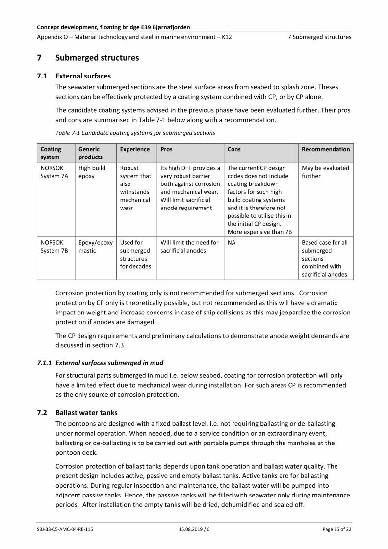
7 Submerged structures
7.1 External surfaces
The seawater submerged sections are the steel surface areas from seabed to splash zone. Theses
sections can be effectively protected by a coating system combined with CP, or by CP alone.
The candidate coating systems advised in the previous phase have been evaluated further. Their pros
and cons are summarised in Table 7-1 below along with a recommendation.
Table 7-1 Candidate coating systems for submerged sections
Coating system
Generic products
Experience Pros Cons Recommendation
NORSOK System 7A
High build epoxy
Robust system that also withstands mechanical wear
Its high DFT provides a very robust barrier both against corrosion and mechanical wear. Will limit sacrificial anode requirement
The current CP design codes does not include coating breakdown factors for such high build coating systems and it is therefore not possible to utilise this in the initial CP design. More expensive than 7B
May be evaluated further
NORSOK System 7B
Epoxy/epoxy mastic
Used for submerged structures for decades
Will limit the need for sacrificial anodes
NA Based case for all submerged sections combined with sacrificial anodes.
Corrosion protection by coating only is not recommended for submerged sections. Corrosion
protection by CP only is theoretically possible, but not recommended as this will have a dramatic
impact on weight and increase concerns in case of ship collisions as this may jeopardize the corrosion
protection if anodes are damaged.
The CP design requirements and preliminary calculations to demonstrate anode weight demands are
discussed in section 7.3.
7.1.1 External surfaces submerged in mud
For structural parts submerged in mud i.e. below seabed, coating for corrosion protection will only
have a limited effect due to mechanical wear during installation. For such areas CP is recommended
as the only source of corrosion protection.
7.2 Ballast water tanks
The pontoons are designed with a fixed ballast level, i.e. not requiring ballasting or de-ballasting
under normal operation. When needed, due to a service condition or an extraordinary event,
ballasting or de-ballasting is to be carried out with portable pumps through the manholes at the
pontoon deck.
Corrosion protection of ballast tanks depends upon tank operation and ballast water quality. The
present design includes active, passive and empty ballast tanks. Active tanks are for ballasting
operations. During regular inspection and maintenance, the ballast water will be pumped into
adjacent passive tanks. Hence, the passive tanks will be filled with seawater only during maintenance
periods. After installation the empty tanks will be dried, dehumidified and sealed off.

Concept development, floating bridge E39 Bjørnafjorden
Appendix O – Material technology and steel in marine environment – K12 7 Submerged structures
SBJ-33-C5-AMC-04-RE-115 15.08.2019 / 0 Page 16 of 22
If the ballast tanks could be completely closed, i.e. sealed off to avoid any oxygen ingress, the need
for corrosion protection will be limited as corrosion will cease when oxygen is depleted provided
there are no additional feed to bacteria. For such tanks addition of a corrosion inhibitor or biocide
may be adequate. The present design does however not allow for completely sealed off water filled
ballast tanks.
The candidate coating systems discussed in the previous phase have been evaluated further and the
results are summarised in Table 7-2 below along with a recommendation. In addition, a corrosion
allowance may be added depending on maintenance philosophy.
Table 7-2 Candidate corrosion protection systems for ballast water tanks
Type of ballast water tank
Type of ballast *)
Candidate corrosion protective means
Comments Recommendation
Active Seawater NORSOK system 7B + CP Zinc is recommended as sacrificial anode
Well proven and durable solution
Rubber lining Requires smooth internal walls, without stiffeners etc.
Not feasible with the present tank design
Tank in tank (in 25Cr DSS or glass fibre reinforced plastic (GRP))
Large opening required to allow tank installation. Stiffeners in ballast tank bottom should be avoided.
Fresh water
High quality coating NA Not relevant since present design is to use seawater
Tank in tank (SS316 or GRP)
NA
Passive Seawater Coating. Will require regular inspections or monitoring
NORSOK system 1
Freshwater NA
Empty **) NA Coating combined with dehumidification
Level of corrosion protection depends upon dehumidification. To be at least below 60%RH
NORSOK system 3G
*) Solid ballast may also be added to the tanks. **) The same coating system as recommended for voids and empty spaces in the upper section is suitable for empty ballast tanks if a relative humidity <60% can be achieved. Alternatively, the same system as for passive tanks is recommended.
7.3 Cathodic protection
The CP design shall be in accordance with a recognised international code. It is to be performed when the structural design is complete and when the design basis for the sacrificial anodes has been decided. Herein, preliminary CP calculations have been carried out for the pontoons to demonstrate anode weight requirements expected to meet 25 years and 50 years exposure based on the recommendations outlined in DNVGL-RP-B401, edition 2017 /Ref. 19/. The parameters applied are summarised in
Table 7-3 below.

Concept development, floating bridge E39 Bjørnafjorden
Appendix O – Material technology and steel in marine environment – K12 7 Submerged structures
SBJ-33-C5-AMC-04-RE-115 15.08.2019 / 0 Page 17 of 22
Table 7-3: CP design parameters from ref. 19 applied in the calculations.
Description Design parameter Value Comments
Al-Zn-In anode Anode current capacity 2000 Ah/kg
Zinc anode Anode current capacity 780Ah/kg
Anode utilisation factor
Anode shape: Long flush 0.85 Factor describing extent of anode mass that can be utilised.
Steel current demand
Average current required per surface area unit
0.1A/m2 Average current demand expected for the pontoons.
Coating breakdown factor
Average value accounting the first 25 years
0.17 Average coating breakdown factors as advised in the code. These values are based on NORSOK system 7B. Average value accounting the
first 50 years 0.32
Uncoated steel 1 Applied for 25Cr DSS if left uncoated
Contingency Factor added to account for design development.
10% Added to CP calculations for external surfaces. For ballast tanks the estimated surface area has a built-in conservatism
The anode weight calculations have been carried out for the external surface area of one pontoon
and for one ballast tank based upon typical dimensions as per present design. The results are
summarised in Table 7-4.
Table 7-4: Typical anode weight demands expected for a pontoon and for an active ballast water tank
Item Description Surface area (m2)
Anode type Anode weight demand if all surface areas are coated (tons)
Anode weight demand if 25Cr DSS is uncoated (tons)
25 years 50 years 25 years 50 years
Pontoon *) Submerged section
1092 Aluminium based anode
3.7 tons 14.1 9.1 22.9
Splash zone 458
Ballast water tank
All submerged except for the roof
1485 Zinc anode 8.3 31.4 NA NA
*) The calculations do not include any anode demand to account for current drain to chains
As demonstrated in Table 7-4 coating of the CRA belt, although not required for corrosion protection,
will have a significant impact on the required anode weight.
It must be underlined that these calculations are based on coating breakdown factors for NORSOK
system 7B which is a 2-coat system resulting a DFT of minimum 350µm. By selecting a high build glass
flake coating system with a DFT exceeding 1000µm, the actual coating breakdown factor is expected
to be much less. However, the current CP design codes give no advice related to this. Furthermore,
experience from the North Sea has revealed that coating breakdown is generally far less than
anticipated in the CP design codes. Consequently, a new revision of DNVGL-RP-B401 is currently
being prepared and it will allow lower coating breakdown factors when coating work is being carried
out in accordance with NORSOK system 7B. This is expected to reduce the anode weight demand
with some 30%.

Concept development, floating bridge E39 Bjørnafjorden
Appendix O – Material technology and steel in marine environment – K12 7 Submerged structures
SBJ-33-C5-AMC-04-RE-115 15.08.2019 / 0 Page 18 of 22
Herein it is therefore suggested to base the initial CP design on maximum 50 years. During operation,
inspections will reveal actual anode consumption and actual coating breakdown factors. Based upon
these findings, the expected anode life can be adjusted, and an update of the CP design can be
planned for when need be.
A conservative approach also applies for the default anode current capacities advised by the design
codes. Once an anode manufacturer has been selected that actual anode current capacity
(demonstrate by long term testing) can be utilised and this alone may decrease anode weight
demand with some 10 to 15%.
Hence, when accounting for the above parameters in the final CP design, the actual anode demand
may be reduced by up to 50% compared to the initial weight calculations given herein. The final
design must also account for anode replacements and include additional brackets to allow
installation of additional anodes later in life.

Concept development, floating bridge E39 Bjørnafjorden
Appendix O – Material technology and steel in marine environment – K12 8 Mooring System
SBJ-33-C5-AMC-04-RE-115 15.08.2019 / 0 Page 19 of 22
8 Mooring System
8.1 General
A general reference is made to Appendix M. The mooring system for concept K12 consist of the
following main components:
Fairlead chain stoppers
Top chain
Wire rope, including sockets
Bottom chain
Suction or gravity anchors
Reference is made to SBJ-31-C4-SVV-26-BA-001 Design Basis – Mooring and Anchor /Ref. 20/. The
mooring equipment and components shall be manufactured according to DNVGL-OS-E301 /Ref. 21/
and other relevant/referenced DNVGL standards.
8.2 Corrosion protection
Corrosion protection for the various components is outlines below:
Table 8-1 Corrosion protection for the various components
Component Type of corrosion protection Remark
Chain stopper / fairlead Coating (system 7B) and cathodic protection
Anodes located on the pontoon and/or on the equipment.
Chain Corrosion allowance (CA) The chains are uncoated
- CA for top chain: 0.2 mm/year * - CA for bottom chain: 0.2 mm/ year
Wire rope and sockets
Wire rope: Coating / sheathed Sockets: Coating (system 7B) and cathodic protection.
According to /Ref. 20/, wire rope sockets shall be coated and cathodically protected. See section 10.2.
Anchors Coating (system 7B) and cathodic protection
Coating to extend ~2 m below mudline. Anodes should be located freely exposed to seawater (not buried).
* According to SBJ-31-C4-SVV-26-BA-001 /Ref. 20/, the corrosion allowance for the top chain shall be
0.8 mm / year. With the current mooring design, the top chain will be permanently submerged and
below the splash zone, and as such, the same allowance as for bottom chain is proposed. This is also
in line with ISO 19901-7 and DNVGL-OS-E301.

Concept development, floating bridge E39 Bjørnafjorden
Appendix O – Material technology and steel in marine environment – K12 9 Design against hydrogen induced stress cracking
SBJ-33-C5-AMC-04-RE-115 15.08.2019 / 0 Page 20 of 22
9 Design against hydrogen induced stress cracking
The splash zone is recommended to be solid 25Cr DSS. This material grade is susceptible to hydrogen
induced stress cracking (HISC) when exposed to CP. How to design against HISC is advised by DNVGL-
RP-F112 /Ref. 23/ and the relevant recommendations to be accounted for herein are:
Avoid fillet welds, sharp edges and crack initiation points
Keep the loads and stresses within the limitations advised
Ensure material selected has fine austenite spacing
As per the present design the solid 25Cr DSS belt in the splash zone will not have any fillet welds and
the smooth geometry does not have any sharp edges or other crack initiating points. The structural
loads are generally very low in this area of the pontoons. In addition, residual stresses from welding
and cold forming shall be considered. Since duplex materials are widely used subsea, e.g. for
flowlines, etc., the loads and residual stresses should not be cause for concern. Finally, it will be
fabricated from rolled plates with thickness well below 25mm and thereby fine austenite spacing is
ensured.
Based upon the above, HISC is not considered to be of real concern.

Concept development, floating bridge E39 Bjørnafjorden
Appendix O – Material technology and steel in marine environment – K12 10 Recommendations for further work
SBJ-33-C5-AMC-04-RE-115 15.08.2019 / 0 Page 21 of 22
10 Recommendations for further work
10.1 Material requirements and fabrication
R762 requires material certificates type 3.2 for structural steel (type 1 and 2). The Norwegian
oil and gas sector has been using NORSOK M-120 Material Datasheets /Ref. 11/ for over 25
years, and irrespective of criticality material certificates type 3.2 has never been used for
general purposes. This requirement is believed to increases cost and should be evaluated.
Evaluate the requirement for qualification of manufacturers of special materials according to
NORSOK M-650 (cost-benefit).
Establish a project MDS for plates in 25Cr DSS.
Allowing use of structural material according to EN 10225 /Ref. 12/ (instead of EN 10025)
should be evaluated.
Evaluate whether TCMP (M/ML) shall be the specified as delivery condition for grade S420
materials, i.e. not allowing use of normalised materials.
Suitability of EN 1090-2 as basis for fabrication and inspection of 25Cr DSS, including dissimilar
welds should be evaluated. If found necessary, a project specification must be established.
10.2 Corrosion protection
Evaluate need for top coat for increased durability and/or need for specific colours where
NORSOK system 3G (zinc ethyl silicate) is specified.
Develop the selected coating systems in more detail with respect to actual products and actual
DFTs. This needs to be done in co-operation with the nominated/selected coating
manufacturers.
Evaluate NORSOK systems 2A and 7A, if required.
Perform a detailed CP design once the bridge design has been completed. Liaise with anode
manufacturer to select suitable anode types and sizes and to be able to utilise the actual anode
current capacity.
Feasibility of providing adequate cathodic protection to the wire rope sockets should be
investigated since proper electrical isolation both to the chains and wire rope may be hard to
obtain.
If further documentation is required, it is suggested to perform a new field test with test
specimens placed in the splash zone, preferably in Bjørnafjorden. The test period should be of
minimum 1 year, preferably 2 years.
Develop a plan for inspections, maintenance and repairs/replacements and advise any
corresponding corrosion allowance required.

Concept development, floating bridge E39 Bjørnafjorden
Appendix O – Material technology and steel in marine environment – K12 11 List of references
SBJ-33-C5-AMC-04-RE-115 15.08.2019 / 0 Page 22 of 22
11 List of references
Ref. 1 ISO 4628 Evaluation of degradation of coatings. Designation of quantity and size of defects, and of intensity of uniform changes in appearance.
Ref. 2 ISO 12944 Corrosion protection of steel structures by protective paint systems
Ref. 3 Statens Vegvesen, Håndbok R762 Prosesskode 2: Standard beskrivelse for bruer og kaier
Ref. 4 NS-EN 1090-1 Execution of steel structures and aluminium structures - Part 1: Requirements for conformity assessment of structural components.
Ref. 5 EN 1993-1-4 Eurocode 3 - Design of steel structures - Part 1-4: General rules - Supplementary rules for stainless steels
Ref. 6 EN 10088-2 Stainless steels - Part 2: Technical delivery conditions for sheet/plate and strip of corrosion resisting steels for general purposes
Ref. 7 EN 10028-7 Flat products made of steels for pressure purposes – Part 7: Stainless steels
Ref. 8 NORSOK M-650 Qualification of manufacturers of special materials
Ref. 9 ASTM G48 Standard Test Methods for Pitting and Crevice Corrosion Resistance of Stainless Steels and Related Alloys by Use of Ferric Chloride Solution
Ref. 10 NORSOK M-630 Material data sheets and element data sheets for piping
Ref. 11 NORSOK M-120 Material data sheets for structural steel
Ref. 12 EN10225 Weldable structural steels for fixed offshore structures - Technical delivery conditions
Ref. 13 SINTEF Korrosjonsbeskyttelse av stålbruer – hvordan oppnå lang levetid, Teknologidagene, 23.09.2015
Ref. 14 Equinor TR0042 Surface preparation and protective coating
Ref. 15 NORSOK M-501 Surface Preparation and Protective Coating
Ref. 16 SINTEF report No. 2018:00258 Bruk av superdupleks stål i marin plaskesone
Ref. 17 NORSOK M-001 Materials selection
Ref. 18 ISO 21457 Materials selection and corrosion control for oil and gas production systems
Ref. 19 DNVGL-RP-B401 Cathodic protection design
Ref. 20 SBJ-31-C4-SVV-26-BA-001 Design Basis – Mooring and Anchor
Ref. 21 DNVGL-OS-E301 Position Mooring
Ref. 22 ISO 19901-7 Petroleum and natural gas industries - Specific requirements for offshore structures - Part 7: Stationkeeping systems for floating offshore structures and mobile offshore units
Ref. 23 DNVGL-RP-F112 Duplex Stainless Steel - design against hydrogen induced stress cracking, June 2018
Ref. 24 EN 1090-2 Execution of steel structures and aluminium structures – Part 2: Technical requirements for steel structures
Related Documents