Global Institute of Technology, Jaipur ITS-1, IT Park, EPIP, Sitapura Jaipur 302022 (Rajasthan) Solution III SEM University Examination 2019 SUBJECT–MATERIAL SCIENCE & ENGG. CODE-3ME4-06 Semester III/Year II RTU Paper Solution Branch – Mechanical Engineering Subject Name – MATERIAL SCIENCE & ENGG. Paper Code –3ME4-06 Date of Exam – Dec 2019

Welcome message from author
This document is posted to help you gain knowledge. Please leave a comment to let me know what you think about it! Share it to your friends and learn new things together.
Transcript
Global Institute of Technology, Jaipur ITS-1, IT Park, EPIP, Sitapura Jaipur 302022 (Rajasthan)
Solution III SEM University Examination 2019
SUBJECT–MATERIAL SCIENCE & ENGG. CODE-3ME4-06 Semester III/Year II
RTU Paper Solution
Branch – Mechanical Engineering
Subject Name – MATERIAL SCIENCE & ENGG.
Paper Code –3ME4-06
Date of Exam – Dec 2019
Global Institute of Technology, Jaipur ITS-1, IT Park, EPIP, Sitapura Jaipur 302022 (Rajasthan)
Solution III SEM University Examination 2019
SUBJECT–MATERIAL SCIENCE & ENGG. CODE-3ME4-06 Semester III/Year II
Global Institute of Technology, Jaipur ITS-1, IT Park, EPIP, Sitapura Jaipur 302022 (Rajasthan)
Solution III SEM University Examination 2019
SUBJECT–MATERIAL SCIENCE & ENGG. CODE-3ME4-06 Semester III/Year II
Global Institute of Technology, Jaipur ITS-1, IT Park, EPIP, Sitapura Jaipur 302022 (Rajasthan)
Solution III SEM University Examination 2019
SUBJECT–MATERIAL SCIENCE & ENGG. CODE-3ME4-06 Semester III/Year II
Global Institute of Technology, Jaipur ITS-1, IT Park, EPIP, Sitapura Jaipur 302022 (Rajasthan)
Solution III SEM University Examination 2019
SUBJECT–MATERIAL SCIENCE & ENGG. CODE-3ME4-06 Semester III/Year II
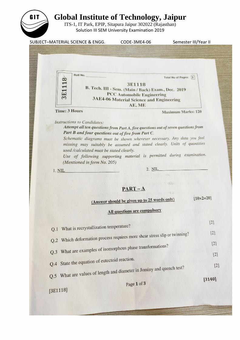
Part A
Q1. Recrystallization is a process by which deformed grains are replaced by a new set of
defect-free grains that nucleate and grow until the original grains have been entirely
consumed.
Q2. The stress required for twinning is comparatively more than slip.
Q3. An isomorphous system is one in which the solid has the same structure for all
compositions. The copper-nickel system is an example.
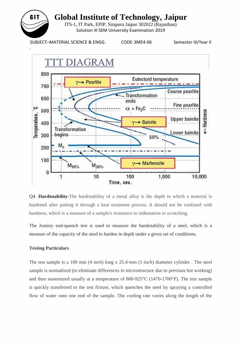
Q4. Eutectoid reaction: at 0.76 %C and 727 °C γ(0.76% C) ↔ α (0.022% C) + Fe3C
In eutectoid reaction, the austenite transforms into a phase mixture of ferrite (containing
0.76% C) and cementite.
Q5. The Jominy end quench test consists of a simple bar 25 mm in diameter by 100 mm long.
Q6. In this process, Austenite is transformed to martensite by step quenching, at a rate fast
enough to avoid the formation of ferrite, pearlite or bainite.
Q7. Chromium is a powerful alloying element in steel. It strongly increases the hardenability
of steel, and markedly improves the corrosion resistance of alloys in oxidizing media. Its
presence in some steels could cause excessive hardness and cracking in and adjacent to
welds. Stainless steels may contain in excess of 12% chromium.
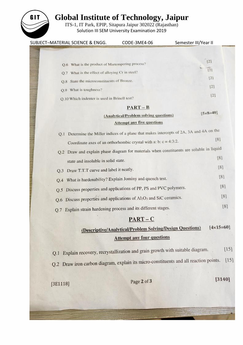
Q8. Bronze is an alloy consisting primarily of copper, commonly with about 12–12.5% tin
and often with the addition of other metals (such as aluminium, manganese, nickel or zinc)
and sometimes non-metals or metalloids such as arsenic, phosphorus or silicon. These
additions produce a range of alloys that may be harder than copper alone, or have other useful
properties, such as stiffness, ductility, or machinability.
Q9. Toughness is the ability of a material to absorb energy and plastically deform without
fracturing.
Q10. Brinell hardness test uses a hardened steel ball as an indenter. It is 10 mm diameter
ball.
Global Institute of Technology, Jaipur ITS-1, IT Park, EPIP, Sitapura Jaipur 302022 (Rajasthan)
Solution III SEM University Examination 2019
SUBJECT–MATERIAL SCIENCE & ENGG. CODE-3ME4-06 Semester III/Year II Part-B
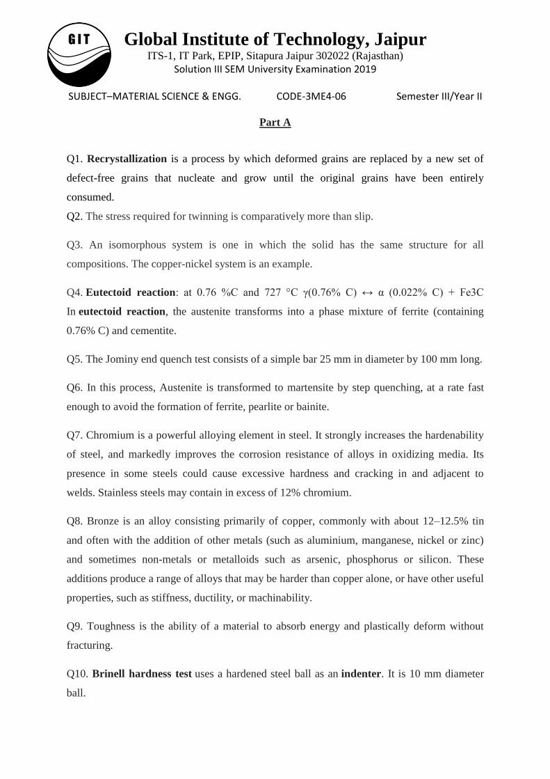
Q1.
X Y Z
Intercepts 2Ǻ 3Ǻ 4Ǻ
Lattice parameters 4x 3x 2x
Ratio 2/4x 3/3x 4/2x
Reciprocal 2x x x/2
Factoring common factors 2 1 1/2
Integer form ( 4 2 1)
Q2.
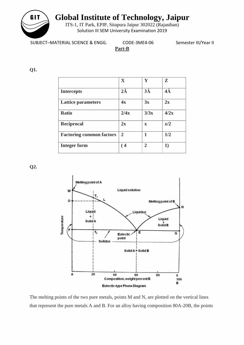
The melting points of the two pure metals, points M and N, are plotted on the vertical lines
that represent the pure metals A and B. For an alloy having composition 80A-20B, the points
Global Institute of Technology, Jaipur ITS-1, IT Park, EPIP, Sitapura Jaipur 302022 (Rajasthan)
Solution III SEM University Examination 2019
SUBJECT–MATERIAL SCIENCE & ENGG. CODE-3ME4-06 Semester III/Year II showing the beginning of solidification T1 and end of solidification TE are plotted as shown.
The same procedure is followed for all other alloys. The upper lines on the phase diagram
connecting the points M, E and N is the liquidus line and shows the beginning of
solidification. The point, at which the liquidus lines intersect, the minimum point E, is known
as the eutectic point. TE is called the eutectic temperature and 40A-60B the eutectic
composition. As solidus line is a continuous line connecting the melting points of pure
metals, the complete solidus line is MFGN.
The phase diagram consists of four areas. The area above the liquidus line is a single-phase
homogeneous liquid solution, since the two metals are soluble in the liquid state (labeled as
Liquid solution). The remaining three areas are two-phase areas.
Every two-phase area on a phase diagram must be bounded along a horizontal line by single
phases. Thus, if single-phase areas are labeled first, than the two-phase areas may be easily
determined.
To determine the phases that exist in the two-phase area MFE in the above diagram, a
horizontal tie line OL is drawn. This line intersects the liquidus at L, which means that liquid
is one of the phases existing in the two-phase area and intersects the left axis at point O. The
left axis represents a single phase, the pure metal A, which below melting point is solid.
Therefore, the two phases existing in the area MFE are liquid and solid A (labeled as Liquid
+ Solid A). By the same logic, the two phases that exist in area NEG are liquid and solid B
(labeled as Liquid + Solid B).
Since the two metals are assumed to be completely insoluble in the solid state, when freezing
starts, the only solid that can form is a pure metal. Thus, every alloy when completely
solidified must be a mixture of the two pure metals. Thus the area below FEG line in above
diagram will be a mixture of two solid pure metals A and B (labeled as Solid A + Solid B).
It is common practice to consider alloys to the left of the eutectic composition as
hypoeutectic alloys and those to the right as hypereutectic alloys.
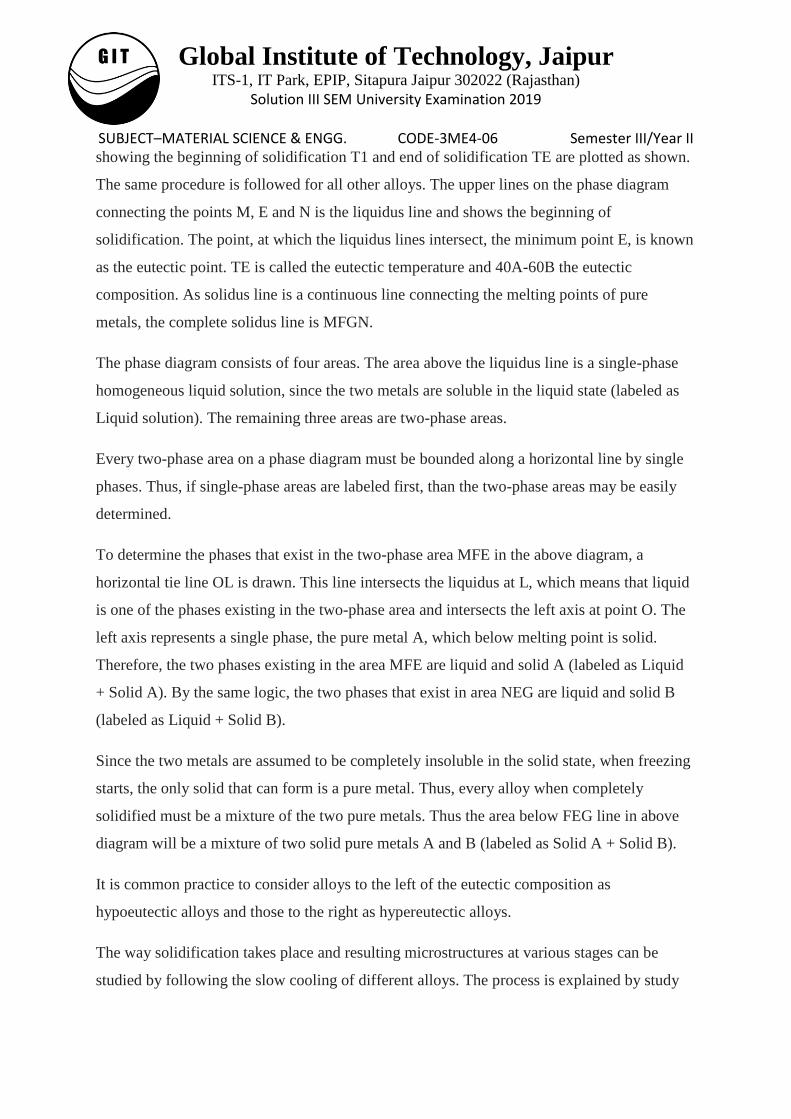
The way solidification takes place and resulting microstructures at various stages can be
studied by following the slow cooling of different alloys. The process is explained by study
Global Institute of Technology, Jaipur ITS-1, IT Park, EPIP, Sitapura Jaipur 302022 (Rajasthan)
Solution III SEM University Examination 2019
SUBJECT–MATERIAL SCIENCE & ENGG. CODE-3ME4-06 Semester III/Year II of slow cooling of Alloy 1 (eutectic composition), Alloy 2 (hypoeutectic alloys) and Alloy 3
(hypereutectic alloys) in the figure given below.
Q3.
Global Institute of Technology, Jaipur ITS-1, IT Park, EPIP, Sitapura Jaipur 302022 (Rajasthan)
Solution III SEM University Examination 2019
SUBJECT–MATERIAL SCIENCE & ENGG. CODE-3ME4-06 Semester III/Year II .
Q4. Hardenability-The hardenability of a metal alloy is the depth to which a material is
hardened after putting it through a heat treatment process. It should not be confused with
hardness, which is a measure of a sample's resistance to indentation or scratching.
The Jominy end-quench test is used to measure the hardenability of a steel, which is a
measure of the capacity of the steel to harden in depth under a given set of conditions.
Testing Particulars
The test sample is a 100 mm (4 inch) long x 25.4-mm (1-inch) diameter cylinder . The steel
sample is normalized (to eliminate differences in microstructure due to previous hot working)
and then austenitzed usually at a temperature of 800-925°C (1470-1700°F). The test sample
is quickly transferred to the test fixture, which quenches the steel by spraying a controlled
flow of water onto one end of the sample. The cooling rate varies along the length of the
Global Institute of Technology, Jaipur ITS-1, IT Park, EPIP, Sitapura Jaipur 302022 (Rajasthan)
Solution III SEM University Examination 2019
SUBJECT–MATERIAL SCIENCE & ENGG. CODE-3ME4-06 Semester III/Year II sample, from very rapid at the quenched end where the water strikes the specimen to slower
rates that are equivalent to air cooling at the other end.
The round specimen is then ground flat along its length on opposite sides to a depth of at least
0.38 mm (0.015 inch) to remove decarburized material. Care should be taken that the
grinding does not heat the sample because this can cause tempering, which can soften the
steel.
Hardness is measured at intervals from the quenched end, typically at 1.5 mm (0.062 inch)
intervals for alloy steels and 0.75 mm (0.031 inch) for carbon steels, beginning as close as
possible to the quenched end. The hardness decreases with distance from the quenched end.
High hardness occurs where high-volume fractions of martensite develop. Lower hardness
indicates transformation to bainite or ferrite/pearlite microstructures.
Measurement of hardness is commonly carried out using a Rockwell or Vickers hardness
tester. Conversion charts are available to relate the different hardness scales if necessary, but
care should be taken to use the correct charts for steel. Rockwell and Vickers hardness
tests deform the metal differently, and the results are affected by work hardening. The
hardenability is described by a hardness curve for the steel or more commonly by reference to
the hardness value at a particular distance from the quenched end.
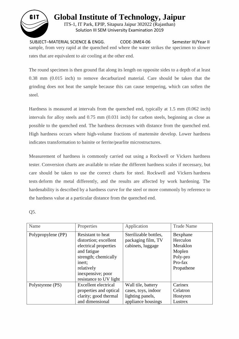
Q5.
Name Properties Application Trade Name
Polypropylene (PP) Resistant to heat
distortion; excellent
electrical properties
and fatigue
strength; chemically
inert;
relatively
inexpensive; poor
resistance to UV light
Sterilizable bottles,
packaging film, TV
cabinets, luggage
Bexphane
Herculon
Meraklon
Moplen
Poly-pro
Pro-fax
Propathene
Polystyrene (PS) Excellent electrical
properties and optical
clarity; good thermal
and dimensional
Wall tile, battery
cases, toys, indoor
lighting panels,
appliance housings
Carinex
Celatron
Hostyren
Lustrex
Global Institute of Technology, Jaipur ITS-1, IT Park, EPIP, Sitapura Jaipur 302022 (Rajasthan)
Solution III SEM University Examination 2019
SUBJECT–MATERIAL SCIENCE & ENGG. CODE-3ME4-06 Semester III/Year II stability; relatively
inexpensive
Styron
Vestyron
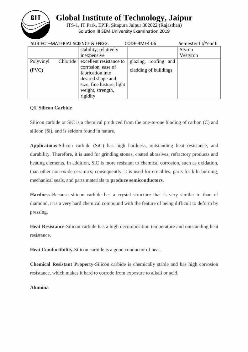
Polyvinyl Chloride
(PVC)
excellent resistance to
corrosion, ease of
fabrication into
desired shape and
size, fine lusture, light
weight, strength,
rigidity
glazing, roofing and
cladding of buildings
Q6. Silicon Carbide
Silicon carbide or SiC is a chemical produced from the one-to-one binding of carbon (C) and
silicon (Si), and is seldom found in nature.
Applications-Silicon carbide (SiC) has high hardness, outstanding heat resistance, and
durability. Therefore, it is used for grinding stones, coated abrasives, refractory products and
heating elements. In addition, SiC is more resistant to chemical corrosion, such as oxidation,
than other non-oxide ceramics; consequently, it is used for crucibles, parts for kiln burning,
mechanical seals, and parts materials to produce semiconductors.
Hardness-Because silicon carbide has a crystal structure that is very similar to than of
diamond, it is a very hard chemical compound with the feature of being difficult to deform by
pressing.
Heat Resistance-Silicon carbide has a high decomposition temperature and outstanding heat
resistance.
Heat Conductibility-Silicon carbide is a good conductor of heat.
Chemical Resistant Property-Silicon carbide is chemically stable and has high corrosion
resistance, which makes it hard to corrode from exposure to alkali or acid.
Alumina
Global Institute of Technology, Jaipur ITS-1, IT Park, EPIP, Sitapura Jaipur 302022 (Rajasthan)
Solution III SEM University Examination 2019
SUBJECT–MATERIAL SCIENCE & ENGG. CODE-3ME4-06 Semester III/Year II Alumina (Al2O3) is a chemical compound of aluminum and oxygen, generally called
aluminum oxide. Aluminum is the third most abundant element on earth after oxygen and
silicon.
Applications
Because high-density sintered body with high purity and high dimensional accuracy can be
relatively easily manufactured with alumina (Al2O3), it is one of the most versatile materials
in application among the ceramics. It is not only used for mechanical applications with
mechanical strength, abrasion resistance, and corrosion resistance, but is also widely used for
electronic engineering applications such as integrated circuit boards using electric insulation,
and optical applications that make use of translucency based on a special production method.
Hardness-Alumina is the hardest of the oxides.
Heat Conductibility-Alumina is a substance whose heat conductibility is relatively great. On
the other hand, its coefficient of thermal expansion is large, and the impact resistance is low
compared to silicon nitride or silicon carbide.
High Electric Insulating Characteristic-Alumina sintered body with less soda has an
electrical resistance of over 1015 Ωcm.
Corrosion Resistance-Alumina is chemically stable and shows excellent corrosion resistance
against chemicals such as acids.
Q7. This is the phenomenon whereby a ductile metal becomes harder and stronger as it is
plastically deformed. Ductile materials show increase in strength and hardness when
plastically deformed at temperature lower than the crystallization temperature. Most metals
stain harden at room temperature. We may note that the temperature at which deformation
takes place is ―cold‖ relative to the absolute temperature of the metal cold working. Cold
working reduces ductility because part of the elongation that takes place is observed during
testing. The cold-working destroys the randomness of grain orientations and the resulting
properties of the material are quite different in various directions. During cold-working
between 1 to 10% of the energy of plastic deformation is stored in the material as internal
Global Institute of Technology, Jaipur ITS-1, IT Park, EPIP, Sitapura Jaipur 302022 (Rajasthan)
Solution III SEM University Examination 2019
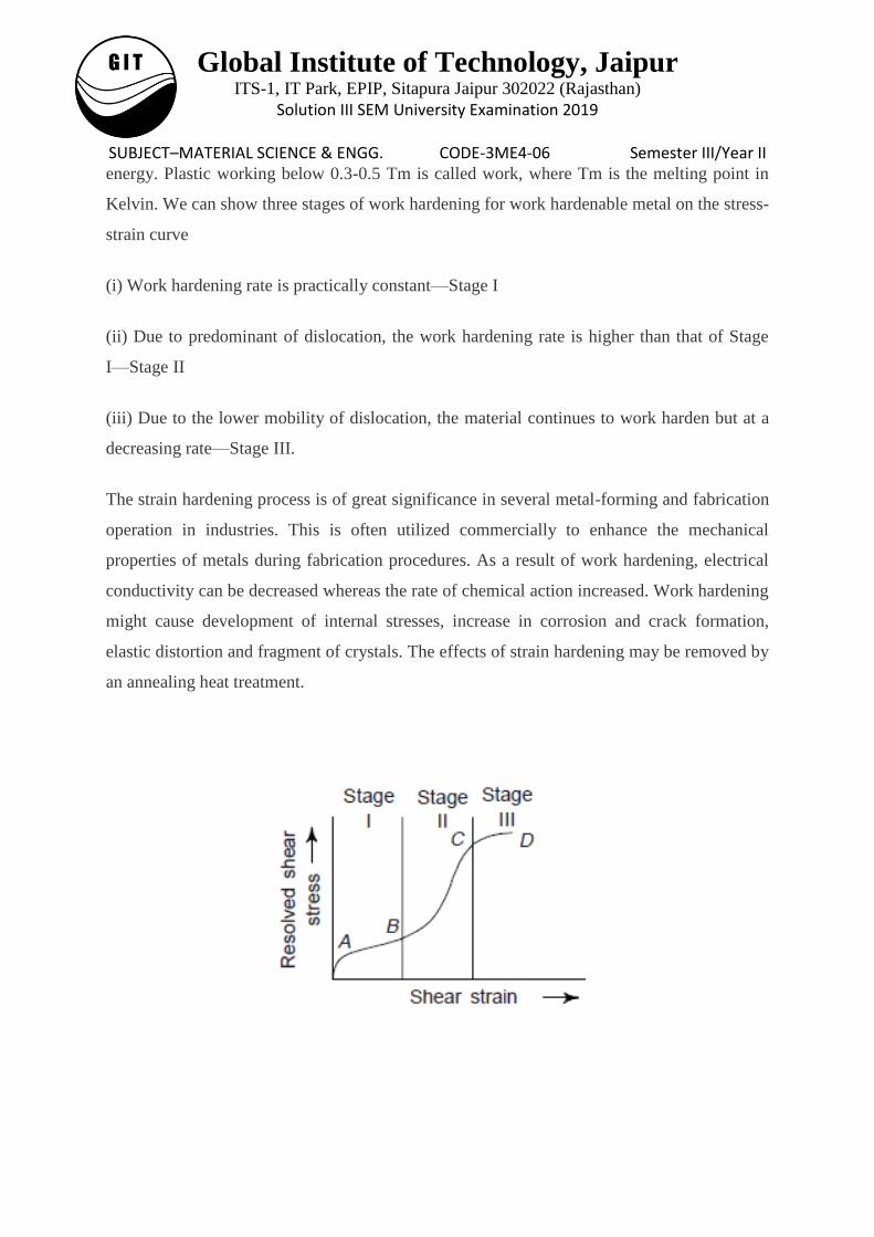
SUBJECT–MATERIAL SCIENCE & ENGG. CODE-3ME4-06 Semester III/Year II energy. Plastic working below 0.3-0.5 Tm is called work, where Tm is the melting point in
Kelvin. We can show three stages of work hardening for work hardenable metal on the stress-
strain curve
(i) Work hardening rate is practically constant—Stage I
(ii) Due to predominant of dislocation, the work hardening rate is higher than that of Stage
I—Stage II
(iii) Due to the lower mobility of dislocation, the material continues to work harden but at a
decreasing rate—Stage III.
The strain hardening process is of great significance in several metal-forming and fabrication
operation in industries. This is often utilized commercially to enhance the mechanical
properties of metals during fabrication procedures. As a result of work hardening, electrical
conductivity can be decreased whereas the rate of chemical action increased. Work hardening
might cause development of internal stresses, increase in corrosion and crack formation,
elastic distortion and fragment of crystals. The effects of strain hardening may be removed by
an annealing heat treatment.
Global Institute of Technology, Jaipur ITS-1, IT Park, EPIP, Sitapura Jaipur 302022 (Rajasthan)
Solution III SEM University Examination 2019
SUBJECT–MATERIAL SCIENCE & ENGG. CODE-3ME4-06 Semester III/Year II Part C
Q1. Plastically deforming a metal specimen at temperatures that are low (~ 25°C) relative to
its absolute melting temperature produces microstructural and property changes. These
include:
(i) a change in grain shape, (ii) strain hardening, and (iii) an increase in dislocation
density.
Some fraction of the energy spent in deformation of the material is stored in the metal
as strain energy. This energy is associated with tensile compressive, and shear zones around
the newly created dislocations. Moreover, other properties, e.g. electrical conductivity and
corrosion resistance may also be modified as a consequence of plastic deformation. One may
revert back these properties and structures to the pre-cold worked states by appropriate heat
treatment, i.e. annealing treatment. Such restoration of properties results from two different
processes that occur at elevated temperatures: recovery and recrystallization, which may be
followed by grain growth. Recovery takes place at relatively low temperatures (below 0.3
Tmp) and recrystallization at higher temperatures.
Recovery: This term implies all changes in the fine structure and properties of a metal
which involve no changes in the microstructure of the deformed metal, i.e., recovery does not
change the size and shape of grains. During recovery, some of the stored internal strain
energy is relieved by virtue of dislocation motion (in the absence of an externally applied
stress), as a result of enhanced atomic diffusion at the elevated temperature. There is some
reduction in the number of dislocations, and dislocation configurations are produced having
low strained energies. Also, physical properties such as electrical and thermal conductivities
and the like are recovered to their precold-worked states. Recovery is further subdivided into
two stages: strain-relief crystallization and polygonization. The former always takes place
during heating of deformed metals, whereas polygonization can develop only under
appropriate conditions. Strain-relief crystallization of a cold-deformed metal is the stage at
which the number of point-defects, mainly vacancies, diminishes; in a number of metals, such
as aluminium and iron, strain-relief crystallization also includes dislocation climb which is
accompanied with interaction of unlike-sign dislocations and results in a noticeable decrease
of dislocation density. Redistribution of dislocations also involves a release of residual
Global Institute of Technology, Jaipur ITS-1, IT Park, EPIP, Sitapura Jaipur 302022 (Rajasthan)
Solution III SEM University Examination 2019
SUBJECT–MATERIAL SCIENCE & ENGG. CODE-3ME4-06 Semester III/Year II stresses. Strain-relief crystallization decreases the electric resistance and increases the density
of a metal. In the general case, the hardness and strength decrease at most by 10-15% from
their initial values and the ductility accordingly increases. After strain-relief crystallization,
the metal has a higher resistance to corrosion cracking.
Recrystallization: This is understood as the nucleation and growth of new grains with a
smaller number of structural defects; recrystallization results in the formation of entirely new,
most often equiaxed crystals. Obviously, recrystallization is the formation of new set of
strain-free and equiaxed grains (i.e., having approximately equal dimensions in all directions)
that have low dislocation densities and characteristic of the precold-worked condition. The
main driving force to produce this new grain structure is the difference in internal energy
between the strained and unstrained material. The new grains form as very small nuclei and
grow until they completely consume the parent material, processes that involve short-range
diffusion. Recrystallization of a cold-worked metals may be used to refine the grain structure.
Moreover, during recrystallization, the mechanical properties that were changed due to cold
working are restored to their pre-cold worked values. This means that the metal becomes
softer, weaker, yet more ductile. Recrystallization in plastically deformed metals can take
place only when the degree of deformation has exceeded a definite critical value called the
critical degree of deformation. With the degree of deformation less than the critical value,
nucleation of new grains during heating is impossible. The critical degree of deformation is
not high (2–8%); it is close to 2% for aluminium and 5% for iron and copper.
Recrystallization is a process the extent of which depend on both time and temperature. The
influence of temperature. Recrystallization is also characterized by a definite recrystallization
temperature (Trec) which is the lowest temperature of heating at which nucleation of new
grains is possible. The recrystallization temperature of a metal constitutes a certain fraction of
its melting point temperature (Tmp). Trec = a Tmp The coefficient a depends on the purity of
metal and degree of plastic deformation.
Grain growth- During recrystallization, the nucleation of new grains occurs in portions of
the highest dislocation density, usually at boundaries of deformed grains. The greater the
plastic deformation, the more recrystallization centres appear in a metal. These centres are
essentially submicroscopic regions with the least quantity of point and linear defects in the
structure. These regions appear due to redistribution and partial annihilation of dislocations.
Global Institute of Technology, Jaipur ITS-1, IT Park, EPIP, Sitapura Jaipur 302022 (Rajasthan)
Solution III SEM University Examination 2019
SUBJECT–MATERIAL SCIENCE & ENGG. CODE-3ME4-06 Semester III/Year II In this process, a low angle boundary appears between a recrystallization centre and
deformed matrix. After a certain time, centres of new grains increase in size due to the
passage of atoms from the deformed surroundings to a more perfect lattice; the high-angle
boundaries of new grains then move into the depth of strained-hardened metal.
Recrystallization of the kind just described is called primary recrystallizatoin. Primary
recrystallization is over after complete substitution of old grains in the entire volume of
deformed metal by new grains Subsequent heating and extension of the holding time, when
the process of primary crystallization has been completed, lead to growth of certain
crystallized grains at the expense of others. This stage of recrystallization is called grain
growth. The process develops spontaneously, provided that the temperature is sufficiently
high, since grain growth results in a decrease of free energy of metal owing to a decrease of
the surface energy (with lager grains, the total surface area of grain boundaries is smaller).
Grain growth does not need to be preceded by recovery and recrystallization; it may occur in
all polycrystalline materials, metals and ceramics alike. Grain growth occurs by the passage
of atoms from one grain to a neighbouring grain through the boundary; in this process some
grains diminish in size and even disappear, while others become large and devour adjacent
grains. Grain growth is accelerated with an increase of temperature. The higher the
temperature of heating, the larger the recrystallized grains.
Global Institute of Technology, Jaipur ITS-1, IT Park, EPIP, Sitapura Jaipur 302022 (Rajasthan)
Solution III SEM University Examination 2019
SUBJECT–MATERIAL SCIENCE & ENGG. CODE-3ME4-06 Semester III/Year II
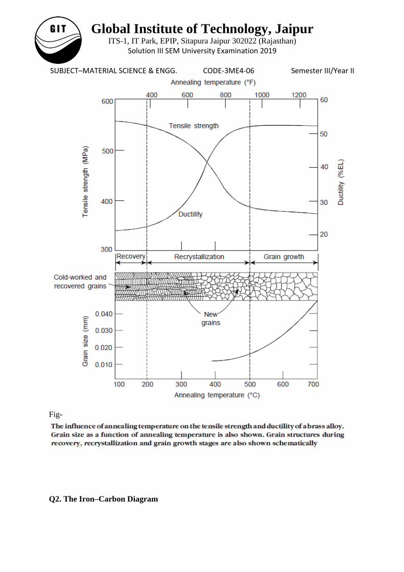
Fig-
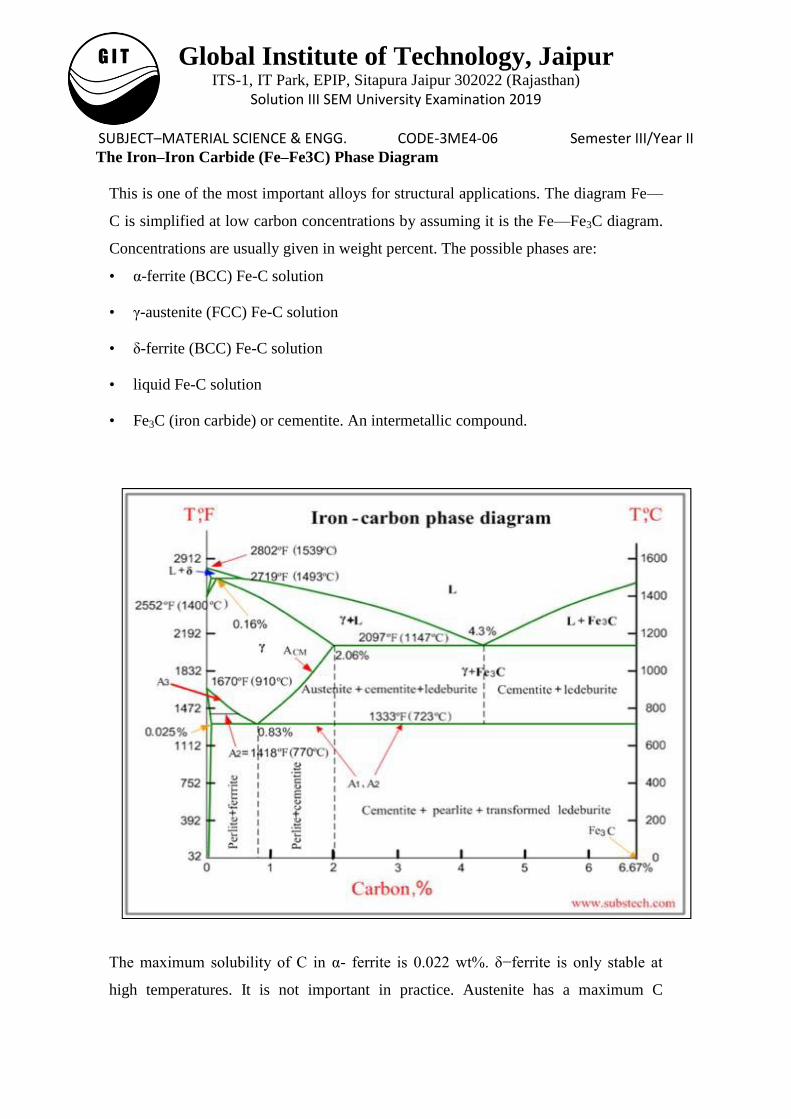
Q2. The Iron–Carbon Diagram
Global Institute of Technology, Jaipur ITS-1, IT Park, EPIP, Sitapura Jaipur 302022 (Rajasthan)
Solution III SEM University Examination 2019
SUBJECT–MATERIAL SCIENCE & ENGG. CODE-3ME4-06 Semester III/Year II The Iron–Iron Carbide (Fe–Fe3C) Phase Diagram
This is one of the most important alloys for structural applications. The diagram Fe—
C is simplified at low carbon concentrations by assuming it is the Fe—Fe3C diagram.
Concentrations are usually given in weight percent. The possible phases are:
• α-ferrite (BCC) Fe-C solution
• γ-austenite (FCC) Fe-C solution
• δ-ferrite (BCC) Fe-C solution
• liquid Fe-C solution
• Fe3C (iron carbide) or cementite. An intermetallic compound.
The maximum solubility of C in α- ferrite is 0.022 wt%. δ−ferrite is only stable at
high temperatures. It is not important in practice. Austenite has a maximum C
Global Institute of Technology, Jaipur ITS-1, IT Park, EPIP, Sitapura Jaipur 302022 (Rajasthan)
Solution III SEM University Examination 2019
SUBJECT–MATERIAL SCIENCE & ENGG. CODE-3ME4-06 Semester III/Year II concentration of 2.14 wt %. It is not stable below the eutectic temperature (727 C)
unless cooled rapidly (Chapter 10). Cementite is in reality metastable, decomposing
into α-Fe and C when heated for several years between 650 and 770 C.
δ-ferrite: – It is solid solution of carbon in δ-iron. Maximum concentration of
carbon in δ- ferrite is 0.09% at 2719 ºF (1493ºC) which is the temperature of the
peritectic transformation. The crystal structure of δ-ferrite is BCC (cubic body
centered).
Austenite: – Austenite is interstitial solid solution of carbon in γ-iron.
Austenite has FCC (cubic face centered) crystal structure, permitting high
solubility of carbon i.e. up to 2.06% at 2097 ºF (1147 ºC). Austenite does not exist
below 1333 ºF (723ºC) and maximum carbon concentration at this temperature
is 0.83%.
α-ferrite: – It is solid solution of carbon in α-iron. α-ferrite has BCC crystal
structure and low solubility of carbon – up to 0.025% at 1333 ºF (723ºC). α-ferrite
exists at room temperature.
Cementite – Cementite is also known as iron carbide, is an intermetallic
compound of iron and carbon, having fixed composition Fe3C. Cementite is a hard
and brittle substance, influencing the properties of steels and cast irons.
Critical temperatures
Upper critical temperature (point) A3 is the temperature, below which ferrite
starts to form as a result of ejection from austenite in the hypo-eutectoid alloys.
Upper critical temperature (point) ACM is the temperature, below which
cementite starts to form as a result of ejection from austenite in the hyper-
eutectoid alloys.
Lower critical temperature (point) A1 is the temperature of the austenite-to-
Pearlite eutectoid transformation. Below this temperature austenite does not exist.
Magnetic transformation temperature A2 is the temperature below which
α-ferrite is ferromagnetic.
Global Institute of Technology, Jaipur ITS-1, IT Park, EPIP, Sitapura Jaipur 302022 (Rajasthan)
Solution III SEM University Examination 2019
SUBJECT–MATERIAL SCIENCE & ENGG. CODE-3ME4-06 Semester III/Year II Phase compositions of the iron-carbon alloys at room temperature
Hypoeutectoid steels (carbon content from 0 to 0.83%) consist of primary
(proeutectoid) ferrite (according to the curve A3) and Pearlite.
Eutectoid steel (carbon content 0.83%) entirely consists of Pearlite.
Hypereutectoid steels (carbon content from 0.83 to 2.06%) consist of primary
(proeutectoid) cementite (according to the curve ACM) and Pearlite.
Cast irons (carbon content from 2.06% to 4.3%) consist of cementite ejected from
austenite according to the curve ACM , Pearlite and transformed ledeburite
(ledeburite in which austenite transformed to pearlite).
When the liquid of eutectic composition is cooled, at or below eutectic temperature
this liquid transforms simultaneously into two solid phases (two terminal solid
solutions, represented by αand β). This transformation is known as eutectic
reactionand is written symbolically as:
Liquid (L) ↔solid solution-1 (α) + solid solution-2 (β)
In the solid state analog of a eutectic reaction, called a eutectoid reaction, one solid
phase having eutectoid composition transforms into two different solid phases.
Another set of invariant reactions that occur often in binary systems are - peritectic
reaction where a solid phase reacts with a liquid phase to produce a new solid phase.
For their role in mechanical properties of the alloy, it is important to note that: Ferrite
is soft and ductile Cementite is hard and brittle. Thus, combining these two phases
in solution an alloy can be obtained with intermediate properties. (Mechanical
properties also depend on the microstructure, that is, how ferrite and cementite are
mixed.)
Development of Microstructures in Iron—Carbon Alloys
The eutectoid composition of austenite is 0.8 wt %. When it cools slowly it forms
perlite, a lamellar or layered structure of two phases: α-ferrite and cementite (Fe3C).
Hypoeutectoid alloys contain proeutectoid ferrite plus the eutectoid pearlite.
Hypereutectoid alloys contain proeutectoid cementite plus pearlite. Since reactions
Global Institute of Technology, Jaipur ITS-1, IT Park, EPIP, Sitapura Jaipur 302022 (Rajasthan)
Solution III SEM University Examination 2019
SUBJECT–MATERIAL SCIENCE & ENGG. CODE-3ME4-06 Semester III/Year II below the eutectoid temperature are in the solid phase, the equilibrium is not achieved
by usual cooling from austenite.
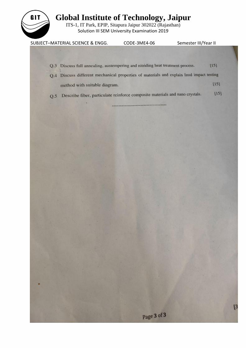
Q3. Full annealing is the process of slowly raising the temperature about 50 ºC (90 ºF)
above the Austenitic temperature line A3 or line ACM in the case of Hypoeutectoid steels
(steels with < 0.77% Carbon) and 50 ºC (90 ºF) into the Austenite-Cementite region in
the case of Hypereutectoid steels (steels with > 0.77% Carbon).
It is held at this temperature for sufficient time for all the material to transform into
Austenite or Austenite-Cementite as the case may be. It is then slowly cooled at the rate
of about 20 ºC/hr (36ºF/hr) in a furnace to about 50 ºC (90 ºF) into the Ferrite-
Cementite range. At this point, it can be cooled in room temperature air with natural
convection. The grain structure has coarse Pearlite
Austempering or Isothermal Quenching: The component or specimen to be hardened is
first austenized and then quenched into a lead or salt bath held at just above the martensite
transformation temperature. The component is kept in the bath until the bainite
transformation is completed. Now, the component is removed from the bath and cooled in air
till the room temperature is reached. The bainite so produced is somewhat softer than
martensite of the same carbon content and distortion is also minimum. Moreover, the
austempered steel has improved shock resistance and low notch sensitivity.
Interestingly, austempering is a heat treatment and no reheating is required as in tempering.
Austempering is often limited to section thickness of 20 mm. This is the only limitation in
austempering, i.e. only small sections are suitable for austempering as big sections cannot be
cooled rapidly to avoid the formation of pearlite. Austempering is applicable to a few plain
carbon steels and requires facility of molten salt bath. One may regard this as a disadvantage
over quenching and tempering.
Nitriding This case-hardening method produces the hardest surface of any of the hardening
processes. It differs from the other methods in that the individual parts have been heat-treated
and tempered before nitriding. The parts are then heated in a furnace that has an ammonia gas
atmosphere. No quenching is required so there is no worry about warping or other types of
distortion. This process is used to case harden items, such as gears, cylinder sleeves,
Global Institute of Technology, Jaipur ITS-1, IT Park, EPIP, Sitapura Jaipur 302022 (Rajasthan)
Solution III SEM University Examination 2019
SUBJECT–MATERIAL SCIENCE & ENGG. CODE-3ME4-06 Semester III/Year II camshafts and other engine parts, that need to be wear resistant and operate in high-heat
areas.
Q4. Mechanical Properties of Material
Yield point. If the stress is too large, the strain deviates from being proportional to the stress.
The point at which this happens is the yield point because there the material yields,
deforming permanently (plastically).
Yield stress. Hooke's law is not valid beyond the yield point. The stress at the yield point is
called yield stress, and is an important measure of the mechanical properties of materials. In
practice, the yield stress is chosen as that causing a permanent strain of 0.002 The yield stress
measures the resistance to plastic deformation. The reason for plastic deformation, in normal
materials, is not that the atomic bond is stretched beyond repair, but the motion of
dislocations, which involves breaking and reforming bonds. Plastic deformation is caused by
the motion of dislocations.
Tensile strength: When stress continues in the plastic regime, the stress-strain passes
through a maximum, called the tensile strength, and then falls as the material starts to develop
a neck and it finally breaks at the fracture point.
For structural applications, the yield stress is usually a more important property than the
tensile strength, since once it is passed, the structure has deformed beyond acceptable limits.
Ductility: The ability to deform before braking. It is the opposite of brittleness. Ductility can
be given either as percent maximum elongation åmax or maximum area reduction.
%EL = åmax x 100 %
%AR = (A0 - Af)/A0
These are measured after fracture (repositioning the two pieces back together).
Resilience: Capacity to absorb energy elastically. The energy per unit volume is the area
under the strain-stress curve in the elastic region.
Global Institute of Technology, Jaipur ITS-1, IT Park, EPIP, Sitapura Jaipur 302022 (Rajasthan)
Solution III SEM University Examination 2019
SUBJECT–MATERIAL SCIENCE & ENGG. CODE-3ME4-06 Semester III/Year II Toughness: Ability to absorb energy up to fracture. The energy per unit volume is the total
area under the strain-stress curve. It is measured by an impact test.
Impact strength is affected by the rate of loading, temperature, and presence of stress raisers
in the material. It is also affected by variations in heat treatment, alloy content, sulphur and
phosphorus content of the material. Impact strength tests are used considerably in some
industries to know shock-absorbing property of the material under the given variations. In
impact tests by high velocity loading and the introduction of a notch to create triaxiality and
stress concentration, a high strain rate is provided. Impact tests are usually conducted on
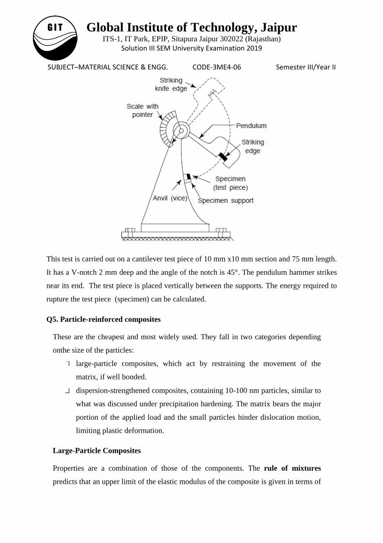
pendulum impact testing machine.
The standard machine for impact testing is of the pendulum type (Fig.). A notch is cut in the
specimen, i.e. a standard test piece which struck under impact conditions by a heavy weight
attached to the end of the pendulum. The test piece, i.e. specimen is held in an anvil (vice)
and is broken by a single blow of the pendulum weight or hammer which is allowed to fall
from a fixed starting point of a known height. The pendulum swings on after breaking the
specimen and the height to which pendulum rises on the other side is measured. Obviously,
the energy absorbed in breaking the specimen may be determined and if this energy is low,
the specimen is brittle. One can also note the impact energy required to break the specimen
from the scale provided on the impact testing machine. When one releases the pendulum
from the position of maximum height or maximum energy, the pointer on the scale also
moves along with the pendulum and stops at a particular position to exhibit the energy
absorbed in breaking and energy still left unutilised. Most test machines are constructed in
such a manner that both types of tests can be used with only minor adjustments.
Global Institute of Technology, Jaipur ITS-1, IT Park, EPIP, Sitapura Jaipur 302022 (Rajasthan)
Solution III SEM University Examination 2019
SUBJECT–MATERIAL SCIENCE & ENGG. CODE-3ME4-06 Semester III/Year II
This test is carried out on a cantilever test piece of 10 mm x10 mm section and 75 mm length.
It has a V-notch 2 mm deep and the angle of the notch is 45°. The pendulum hammer strikes
near its end. The test piece is placed vertically between the supports. The energy required to
rupture the test piece (specimen) can be calculated.
Q5. Particle-reinforced composites
These are the cheapest and most widely used. They fall in two categories depending
onthe size of the particles:
large-particle composites, which act by restraining the movement of the
matrix, if well bonded.
dispersion-strengthened composites, containing 10-100 nm particles, similar to
what was discussed under precipitation hardening. The matrix bears the major
portion of the applied load and the small particles hinder dislocation motion,
limiting plastic deformation.
Large-Particle Composites
Properties are a combination of those of the components. The rule of mixtures
predicts that an upper limit of the elastic modulus of the composite is given in terms of
Global Institute of Technology, Jaipur ITS-1, IT Park, EPIP, Sitapura Jaipur 302022 (Rajasthan)
Solution III SEM University Examination 2019
SUBJECT–MATERIAL SCIENCE & ENGG. CODE-3ME4-06 Semester III/Year II the elastic moduli of the matrix (Em) and the particulate (Ep) phases by:
Ec = EmVm + EpVp
where Vm and Vp are the volume fraction of the two phases. A lower bound is given by:
Ec = EmEp / (EpVm + EmVp)
Fiber-reinforced composites
In many applications, like in aircraft parts, there is a need for high strength per unit
weight (specific strength). This can be achieved by composites consisting of a
lowdensity (and soft) matrix reinforced with stiff fibers.
The strength depends on the fiber length and its orientation with respect to the
stress direction. The efficiency of load transfer between matrix and fiber depends
on the interfacial bond.
Nano-materials
Nanostructured materials are those materials whose structural elements—clusters,
crystallites or molecules have dimensions in the range of 1-100 nm. These small
groups of atoms, in general, go by different names such as nanoparticles, nanocrystals,
quantum dots and quantum boxes. Substantial work is being carried out in the domain
of nanostructured materials and nanotubes during the past decade since they were
found to have potential for high technology engineering applications. One finds a
remarkable variations in fundamental electrical, optical and magnetic properties that
occur as one progresses from an ‗infinitely extended‘ solid to a particle of material
consisting of a countable number of atoms. The various types of nanostructured
materials which has been considered for applications in opto-electronic devices and
quantum- optic devices are nano-sized powders of silicon, silicon-nitride (SiN),
silicon-carbide (SiC) and their thin films. Some of these are also used as advanced
ceramics with controlled micro structures because their strength and toughness
increase when the grain size diminishes. Carbon- based nanomaterials and
nanostructures including fullerenes and nanotube plays an increasingly pervasive role
in nanoscale science and technology. Today, nanotechnology is being heralded as the
next enabling technology that will redesign the future of several technologies,
products and markets.
Related Documents


![[MatErial codE standards] - BRELECT · [MatErial codE standards] Material codes and names and their respective naming rules are managed in accordance with the prescribed standards.](https://static.cupdf.com/doc/110x72/5bfa875b09d3f24c058c838f/material-code-standards-material-code-standards-material-codes-and-names.jpg)