meinschaft er Helmholtz-Gem Mitglied d Association EURATOM – FZJ Material challenges for plasma facing components in future fusion reactors C. Thomser , A. Buerger, J. Linke, T. Loewenhoff, G. Pintsuk, M. Roedig, A. Schmidt, M. Wirtz, L. Singheiser Institute of Energy and Climate Research (IEK) 5th INTERNATIONAL CONFERENCE ON THE FRONTIERS OF PLASMA PHYSICS AND TECHNOLOGY 18-22 April 2011, Singapore

Welcome message from author
This document is posted to help you gain knowledge. Please leave a comment to let me know what you think about it! Share it to your friends and learn new things together.
Transcript
mei
nsch
aft
er H
elm
holtz
-Gem
Mitg
lied
d
Association EURATOM – FZJ
Material challenges for plasma facing components in future fusion reactors
C. Thomser, A. Buerger, J. Linke, T. Loewenhoff, G. Pintsuk, M. Roedig, A. Schmidt, M. Wirtz, L. Singheiser
p
Institute of Energy and Climate Research (IEK)
5th INTERNATIONAL CONFERENCE ON THE FRONTIERS OF PLASMA PHYSICS AND TECHNOLOGY
18-22 April 2011, Singapore
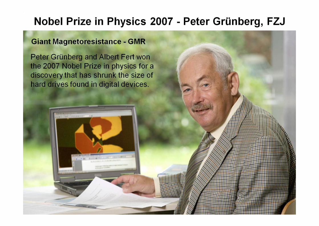
Research Centre JülichResearch & Development on 2 2 km2Research & Development on 2.2 km
Research AreasHealth
Energy & Environment
Information
Key technologiesKey technologiesTotal budget: 532 million €
Employees: 4 608
mei
nsch
aft
er H
elm
holtz
-Gem
Mitg
lied
d
C Thomser: “Material challenges for plasma facing components in future fusion reactors”
Association EURATOM – FZJ
C. Thomser: Material challenges for plasma facing components in future fusion reactors
Outline
A Wall loading conditions & materialsB Quasi-stationary loads & thermal fatigue behaviourC Intense transient loads & thermal shock resistanceD Neutron induced material degradation
AWall loading conditionsWall loading conditions
& materials

fusion devices:Plasma facing components
fusion devices:
TEXTOR JET ITER DEMO
heat removal:actively cooled PFCspassively cooled PFCs
t H li id t l
heat removal:
water He, liquid metal
tritium fuel: increased T inventory
neutrons
n-induced material degradation
10-9 dpa 1 dpa 102 dpa0 dpa
neutronslife time fluence:
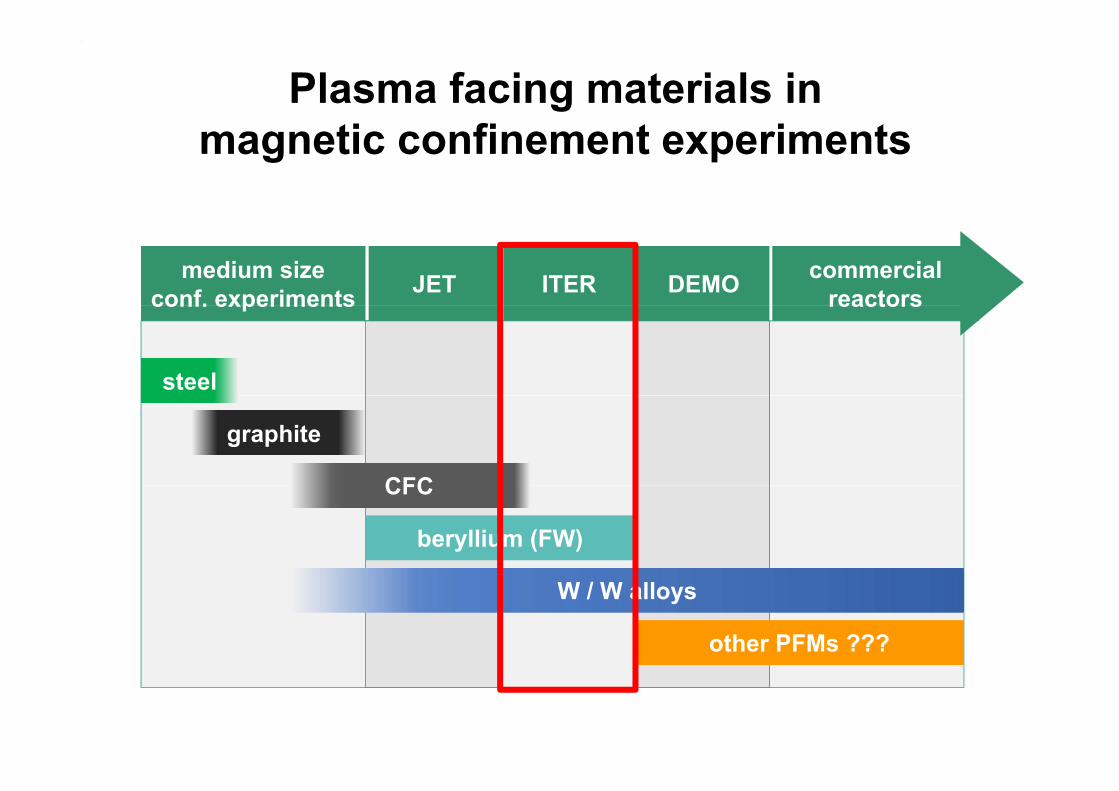
Plasma facing materials in ti fi t i tmagnetic confinement experiments
medium sizeconf. experiments JET ITER DEMO commercial
reactorsconf. experiments reactors
steel
graphite
CFC
beryllium (FW)
CFC
W / W alloys
other PFMs ???

Plasma facing materials for ITER
Advantages DisadvantagesBe • low Z
• no chemical sputtering
hi h th l
• low melting point• toxicity• short erosion lifetime
• high thermal conductivity
• low neutron radiation resistance
W • high melting point • good thermal conductivity
• high Z• high DBTT• neutron embrittlement
• low tritium retention
CFC • low Z • high erosion rate at highCFC• high thermal shock
resistance• high thermal
temperatures• tritium retention• reduction of thermal
conductivity• no melting
conductivity after neutron irradiation
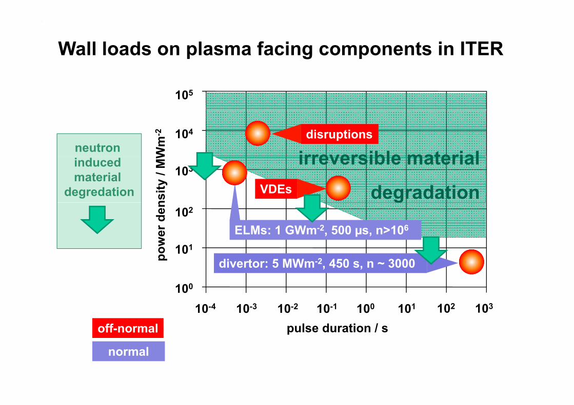
Wall loads on plasma facing components in ITER
105
irreversible material104
Wm
-2 disruptionsneutron irreversible material
degradation103
nsity
/ M
W
VDEs
inducedmaterial
degredation g102
101ower
den
ELMs: 1 GWm-2, 500 µs, n>106
101
100
po divertor: 5 MWm-2, 450 s, n ~ 3000
10010-4 10-3 10310210110-2 10-1
pulse duration / soff-normal
normal
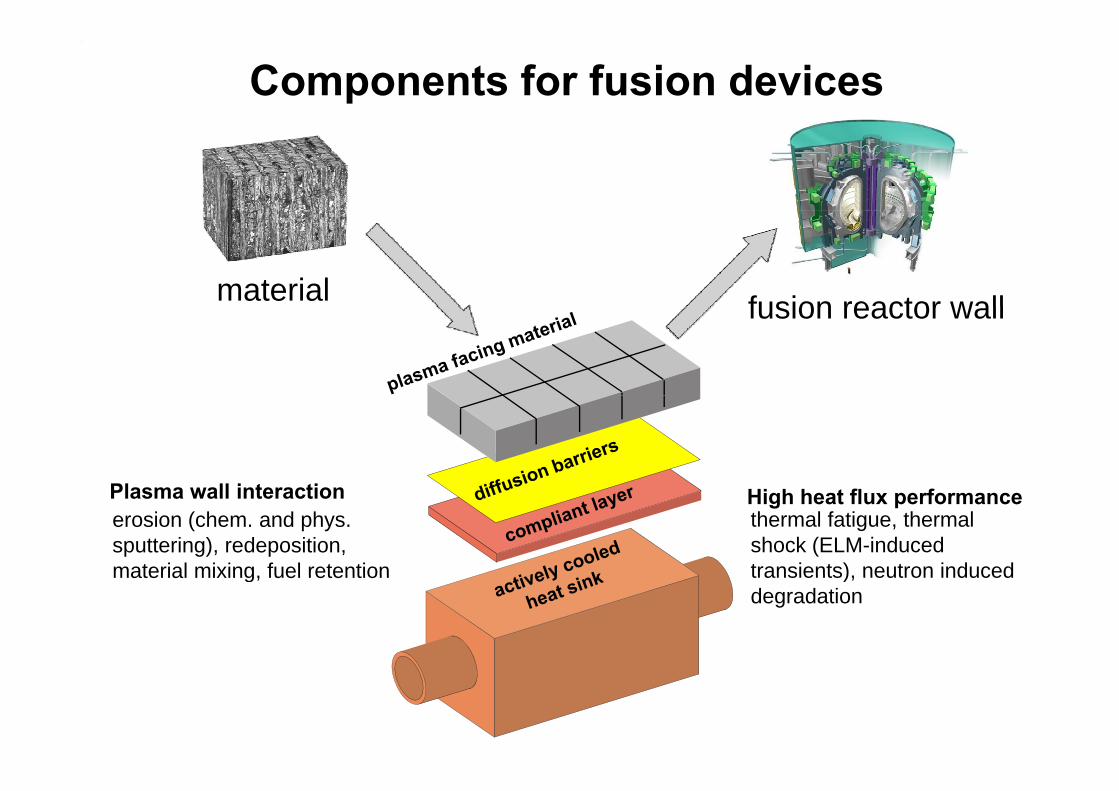
Components for fusion devices
material fusion reactor wallfusion reactor wall
Pl ll i t tierosion (chem. and phys. sputtering), redeposition, material mixing fuel retention
thermal fatigue, thermal shock (ELM-induced transients) neutron induced
Plasma wall interaction High heat flux performance
material mixing, fuel retention transients), neutron induced degradation
BQuasi-stationary loads &Quasi stationary loads &thermal fatigue behaviourg

JUDITH
J li h Di t T t
JU
Juelich Divertor Test Facility Hot Cells (JUDITH)
Judith was an Old Testament Jewish heroine. In the Apocryphal 'Book of Judith', she is portrayed as a widow who made her way into the tent of Holofernes, general of Nebuchadrezzar, cut off his head, and so saved her native town of Bethulia.
Gustav Klimt, Judith I, 1901
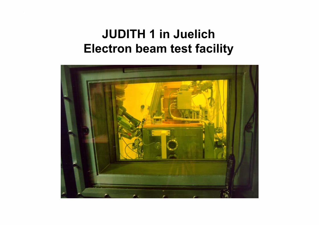
JUDITH 1 in JuelichJUDITH 1 in JuelichElectron beam test facility
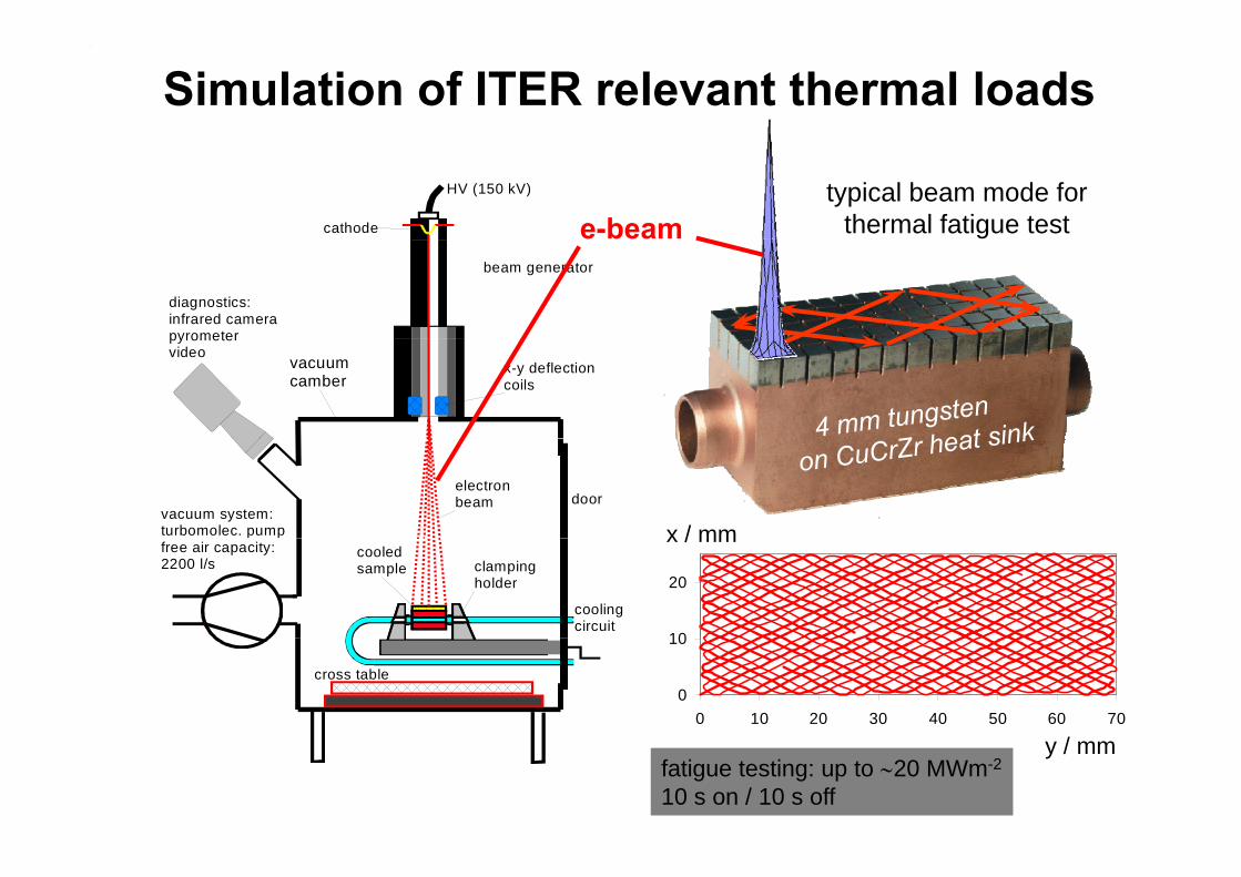
Simulation of ITER relevant thermal loads
HV (150 kV)
cathode e-beamtypical beam mode for
thermal fatigue test
diagnostics:infrared camerapyrometer
beam generator
pyrometervideo
x-y deflectioncoils
vacuum camber
doorvacuum system:turbomolec. pump
electronbeam
x / mmclampingholder
cooledsample
coolingcircuit
free air capacity:2200 l/s
10
20
x / mm
cross table0
10
0 10 20 30 40 50 60 70
/y / mmfatigue testing: up to 20 MWm-2
10 s on / 10 s off

Fatigue testing on plasma facing components for ITER
CFC armour tungsten armourde
sign
CFC flat tile W macrobrush
lat t
ile d
Silicon doped CFC NS31, active metal WLa2O3 tiles with OFHC-Cu, fn
1000 cycles @ 19 MWm-2 1000 cycles @ 18 MWm-2casting, e-beam welding to CuCrZr heat sink e-beam welding to CuCrZr heat sink
k de
sign
CFC monoblock W monoblock
nobl
ock
drilling of CFC tiles (NB31) active metal l ll t h i d illi f WL O
mon
1000 cycles @ 25 MWm-2 1000 cycles @ 20 MWm-2
drilling of CFC tiles (NB31), active metal casting (AMC®) low temperature HIPing
lamellae technique, drilling of WLa2O3blocks, casting with OFHC-Cu, HIPing

CIntense transient loads &
CIntense transient loads &thermal shock resistance
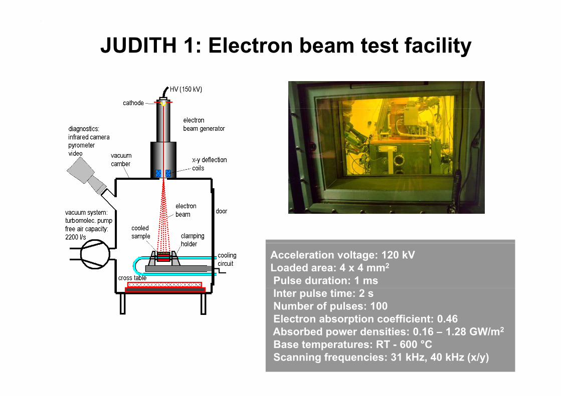
JUDITH 1: Electron beam test facility
Acceleration voltage: 120 kVLoaded area: 4 x 4 mm2
Pulse duration: 1 msInter pulse time: 2 sNumber of pulses: 100Electron absorption coefficient: 0.46Absorbed power densities: 0 16 – 1 28 GW/m2Absorbed power densities: 0.16 – 1.28 GW/mBase temperatures: RT - 600 °CScanning frequencies: 31 kHz, 40 kHz (x/y)

Transient heat load tests on tungstenElectron beam simulation of ELM-specific thermal loads (Δt = 1 ms; n = 100)
0.63 GW/m² at RTW-UHP
p ( ; )
0 63 GW/m² at 400°C0 16 GW/m² at 400°C 0.63 GW/m at 400 C0.16 GW/m at 400 C
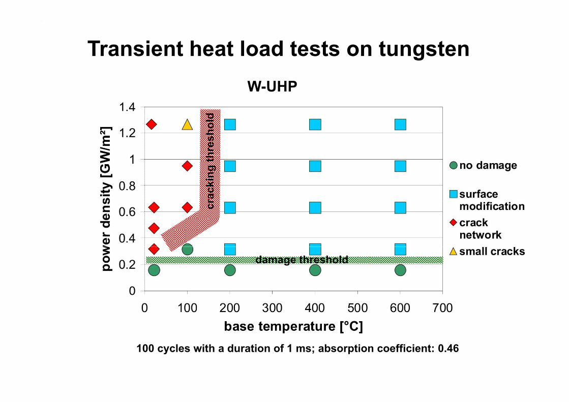
Transient heat load tests on tungstenW-UHP
hres
hold
rack
ing
thcr
damage threshold
100 cycles with a duration of 1 ms; absorption coefficient: 0.46
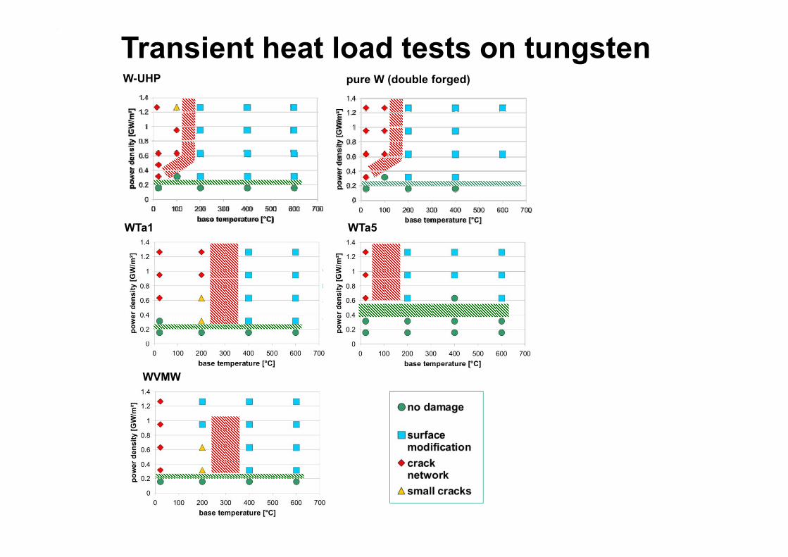
W-UHP pure W (double forged)
Transient heat load tests on tungsten
WTa1 WTa5
WVMW

Tungsten coatings on CFC substrate
WW
Mo
MoW
CFC substrate
25 µm

Damage typesg yp
Surface modification CrackingSurface modification Cracking
Cracking / delamination Cracking / delamination / melting
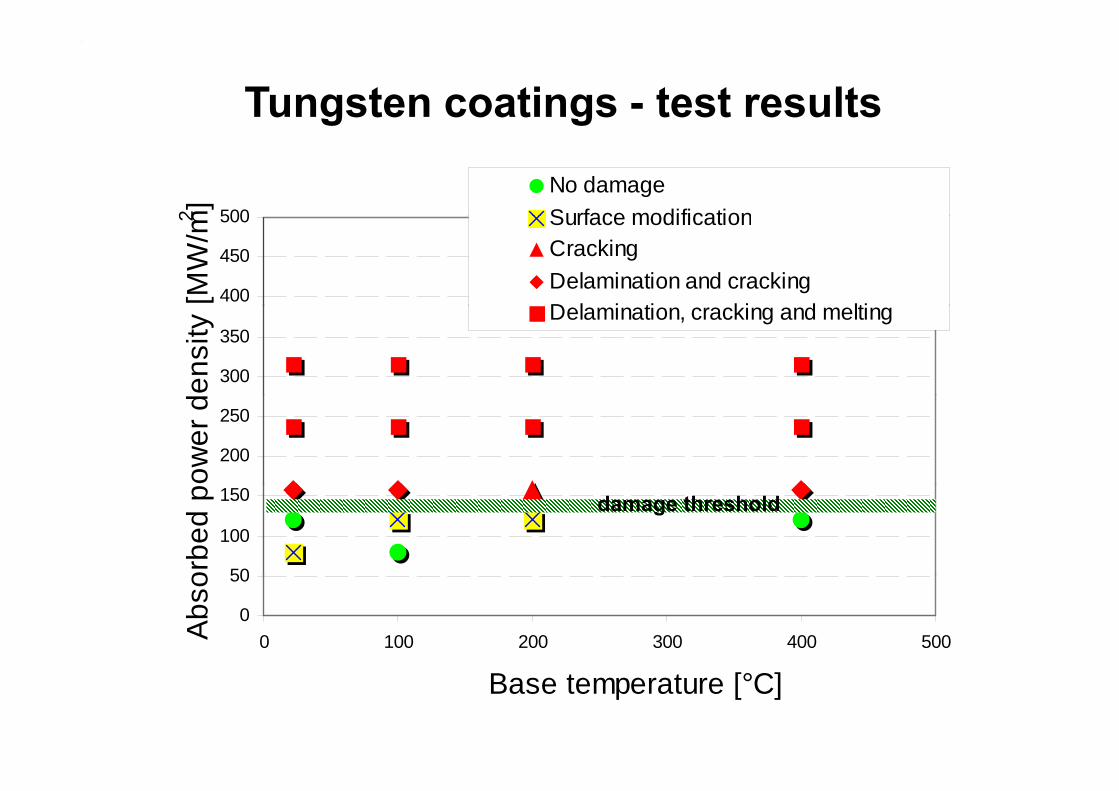
Tungsten coatings - test results
500m2 ] No damageSurface modification
400
450
500[M
W/m
2 Surface modificationCrackingDelamination and crackingD l i ti ki d lti
300
350
ensi
ty Delamination, cracking and melting
200
250
ower
d
50
100
150
orbe
d p damage threshold
0
50
0 100 200 300 400 500Abs
o
Base temperature [°C]
DNeutron induced materialNeutron induced material
degradationg
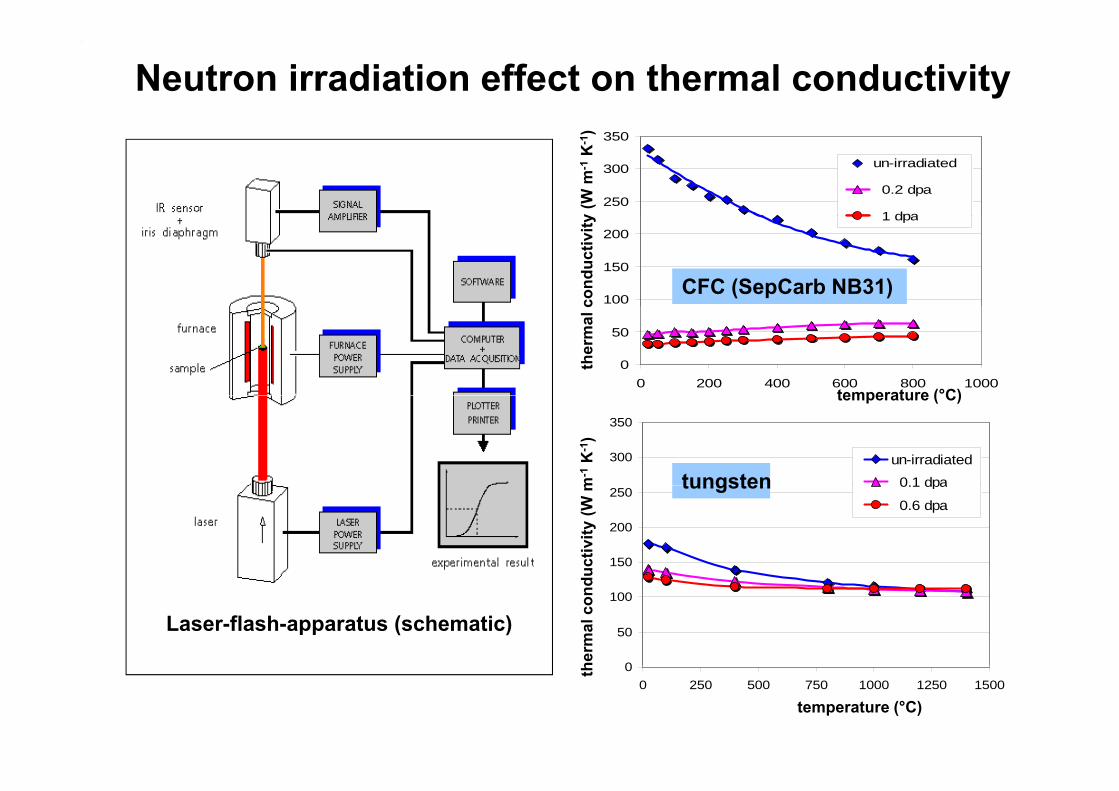
Neutron irradiation effect on thermal conductivity
250
300
350
un-irradiated
0.2 dpa
1 dpay (W
m-1
K-1
)
100
150
200 1 dpa
cond
uctiv
ity
CFC (SepCarb NB31)
0
50
0 200 400 600 800 1000
ther
mal
c
temperature (°C)
m-1
K-1
)
300
350
un-irradiated
0 1 dpa
temperature ( C)
tungsten
uctiv
ity (W
m150
200
250
y
0.1 dpa
0.6 dpatungsten
herm
al c
ondu
0
50
100
Laser-flash-apparatus (schematic)
th
temperature (°C)
00 250 500 750 1000 1250 1500
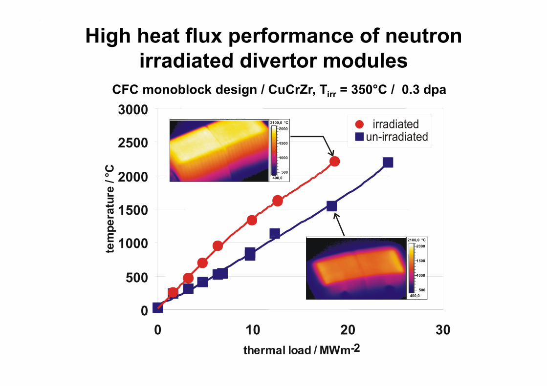
High heat flux performance of neutron irradiated divertor modulesirradiated divertor modules
3000CFC monoblock design / CuCrZr, Tirr = 350°C / 0.3 dpa
2500
3000IR - 551_11~1.IMG
2100,0 °C
1500
2000 bestrahltunbestrahlt
2000
re/°
C
25:09:97 09:59:34
400,0500
1000
1500
mpe
ratu
r
IR - DZ150SS.IMD
500
1000tem 2100,0 °C
1000
1500
2000
0
500Zykliertests an CFC-Modulen vom Type N07.08.96
400,0500
0 10 20 30thermal load / MWm-2
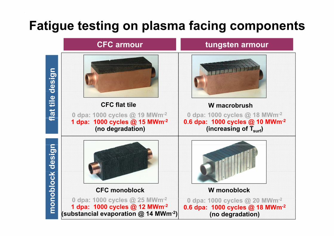
Fatigue testing on plasma facing componentsCFC armour tungsten armour
desi
gn
CFC flat tile W macrobrush
lat t
ile d
0 dpa: 1000 cycles @ 19 MWm-2 0 dpa: 1000 cycles @ 18 MWm-2
fn
p y @1 dpa: 1000 cycles @ 15 MWm-2
(no degradation)
p y @0.6 dpa: 1000 cycles @ 10 MWm-2
(increasing of Tsurf)
k de
sign
CFC monoblock W monoblock
nobl
ock
0 d 1000 l @ 25 MW 2 0 d 1000 l @ 20 MW 2
mon 0 dpa: 1000 cycles @ 25 MWm-2
1 dpa: 1000 cycles @ 12 MWm-2
(substancial evaporation @ 14 MWm-2)
0 dpa: 1000 cycles @ 20 MWm-2
0.6 dpa: 1000 cycles @ 18 MWm-2
(no degradation)
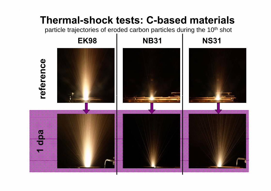
particle trajectories of eroded carbon particles during the 10th shotThermal-shock tests: C-based materials
EK98particle trajectories of eroded carbon particles during the 10 shot
NB31 NS31nc
eef
ere
rpa
1 dp

SummarySummaryMaterials characterization
• an extensive data base is required including microstructure and all physical properties (mechanical, thermal, electrical, optical etc.)
• these parameters are required for monolithic materials coatings and• these parameters are required for monolithic materials, coatings and interlayers for a wide temperature range & different material treatment
Thermal fatigue and thermal shockThermal fatigue and thermal shock • technical solutions for cyclic thermal loads up to ~20 MWm-2 are available
(CFC- or W-monoblocks represent a very robust design solution)• effect of ELMs needs further analyses
Material degradation by energetic neutrons
• the surface temperature of carbon based high heat flux components is significantly increased after neutron irradiation
• the thermal conductivity is decreased significantly (e.g. graphite / CFC)
significantly increased after neutron irradiation
Related Documents