Scope: Barrie, Ontario 120 Mapleview Dr. West, L4N 9H6 Barrie Brampton, Ontario 1620 Steeles Ave. E, L6T 1A4 Brampton Edgerton, Ohio 228 E Morrison St, 43517 Ohio Huntsville, Alabama 9650 Kellner Rd. SW, 35824 Alabama Ionia, Michigan 401 S Steele St, 48846 Troy, Michigan 830 Kirts Blvd Suite 100, 48084 Saltillo, Mexico Facilities included in guidelines: Michigan This standard applies specifically to check fictures constructed for use at MatcorMatsu and its suppliers.This manual should be referenced when quoting, designing or manufacturing assembled parts inspection fixtures for MM Automotive Group. Any deviation from these standards without written permission from the plant in charge, could result in the manufacture accruing the cost to modify or repair the inspection fixture to meet these standards. Libramiento Oscar Flores Tapia Núm. 1905, Int.10 Parque Industrial Amistad Aeropuerto 4, Etapa, Ramos Arizpe, Coahuila, 25900 Mexico MatcorMatsu Automotive Group COMPONENT/CHILD, ASSEMBLY, / & CMM/CAR SET REV 003 Matcor.Matsu.Fixture.Specification

Welcome message from author
This document is posted to help you gain knowledge. Please leave a comment to let me know what you think about it! Share it to your friends and learn new things together.
Transcript

Scope:
Barrie, Ontario 120 Mapleview Dr. West, L4N 9H6 Barrie
Brampton, Ontario 1620 Steeles Ave. E, L6T 1A4 Brampton
Edgerton, Ohio 228 E Morrison St, 43517 Ohio
Huntsville, Alabama 9650 Kellner Rd. SW, 35824 Alabama
Ionia, Michigan 401 S Steele St, 48846
Troy, Michigan 830 Kirts Blvd Suite 100, 48084
Saltillo, Mexico
Facilities included in guidelines:
Michigan
This standard applies specifically to check fictures constructed for use at MatcorMatsu
and its suppliers.This manual should be referenced when quoting, designing or
manufacturing assembled parts inspection fixtures for MM Automotive Group. Any
deviation from these standards without written permission from the plant in charge,
could result in the manufacture accruing the cost to modify or repair the inspection
fixture to meet these standards.
Libramiento Oscar Flores Tapia Núm. 1905,
Int.10 Parque Industrial Amistad Aeropuerto
4, Etapa, Ramos Arizpe, Coahuila, 25900
Mexico
MatcorMatsu Automotive Group
COMPONENT/CHILD, ASSEMBLY, / & CMM/CAR SET
REV 003 Matcor.Matsu.Fixture.Specification

I) Cover page, Scope, with manufacturing facility list
ii) Table of Contents
iii) Terms & Change Log
iv) Fixture Concept Template
v) Fixture Concept Example
vi) Design Review Check Sheet
vii) Inspection Fixture Buyoff Check Sheet
1 General information
2 General information (Cont'd)
Component Part (Stamping) Inspection fixtures
3 Base Plate Information
4 Base Plate Information (Cont'd)
5 General Datum and Net Information
6 Datum and Net Tolerances,
General Component Part Set Information
7 Fixture Block, Profiles, SPC Points, and Pins
8 Fixture Block, Profiles, SPC Points, and Pins (Cont'd)
9 Fixture Block, Profiles, SPC Points, and Pins (Cont'd)
10 Fixture Block, Profiles, SPC Points, and Pins (Cont'd),
Tolerances
11 CMM/Car Setup Stand Design Options
12 General Information on CMM/Car Setup Stands
13 Conducting Business with MM Group
14 Fixture Verification
15 Quoting Inspection Fixtures with MM Automotive Group
Manufacturing Guidelines
16 Lessons Learned
TABLE OF CONTENTS
REV 003 Matcor.Matsu.Fixture.Specification

REFERENCED TERMS USED
D/C - Design change or engineering change
Assembly - Final assembly parts
Sub Assembly - Assembly Parts, but not the final assembly.
Component part - Individual stamped parts that make up assembled parts.
Printed, saved copies of this Fixture Specification are Uncontrolled.
Revision Who When
000 Joel Giles June 23 2017
001
Mircea
Iordachescu 25-Nov-19
002
David
Rosenlund 06-Apr-20
003
Mircea
Iordachescu 03-Feb-21
Various
Location: Blvd Industria Automotriz No. 3052, 25900, Saltillo, Mexico removed from the Facilities list
For all Question during concept, design, and manufacturing phases please contact the specified
plant.
Change History
Details of Change
Initial Corporate Fixture Standard Creation, and approval from all plants.
Cart added for specific weight, fixtures metal handles, reinforced base, new location in Saltillo
REV 003 Matcor.Matsu.Fixture.Specification

COMP
PART NO# Net Pads with clamps
CHILD PART: Removable 3.0mm Net Pads
Templates 3plcs
D/C Removable BlockPART NO#: LEVEL
Notes: Fixture construction is to follow MM Automotive Group fixture standards, & any other OEM Standards
CONCEPT APPROVAL SIGN OFF AREA (USE INK ONLY)
APPROVAL APPROVAL APPROVAL APPROVAL APPROVAL ISSUERMODEL:
LEVEL REVISION DATE ISSUE
INSPECTION FIXTURE CONCEPT
Notes:
1. Body line shall be marked on fixture at every 100mm.2. T,B,H or X,Y,Z datums shall be identified on fixture.(For measurement).3. All holes with general tolerances shall be marked by scribe line unless otherwise specified.
4. Model color: TBD6. Gap or flushness shall conform to MM Group Std7. Flush check shall have a minimum of 30mm flush surface.
OEM Asset information:
If the fixture concept is not customer specific, this would be the standard.
REV 003 Matcor.Matsu.Fixture.Specification

MOTHER PART: STIFF COMP ROOF PANEL
PART NO# 62110-TLAA-A000-H1 Net Pads with clamps
CHILD PART: TLAA-F Removable 3.0mm Net Pads
597 Templates 3 plcsD/C Removable Block
PART NO#: LEVEL
Notes: Fixture construction is to follow MM Automotive Group fixture standards
PAGE 1 of 6
PAGE 2 of 6
PAGE 3 of 6
PAGE 4 of 6
PAGE 5 of 6
PAGE 5 of 6
MODEL: TLAACONCEPT APPROVAL SIGN OFF AREA (USE INK ONLY)
APPROVAL APPROVAL APPROVAL APPROVAL APPROVAL ISSUER
0LEVEL REVISION DATE ISSUE
APPROVAL ISSUER
CONCEPT APPROVAL SIGN OFF AREA (USE INK ONLY)
APPROVAL APPROVAL APPROVAL APPROVAL
APPROVAL
CONCEPT APPROVAL SIGN OFF AREA (USE INK ONLY)
APPROVAL APPROVAL APPROVAL APPROVAL ISSUER
CONCEPT APPROVAL SIGN OFF AREA (USE INK ONLY)
APPROVAL APPROVAL APPROVAL APPROVAL APPROVAL ISSUER
CONCEPT APPROVAL SIGN OFF AREA (USE INK ONLY)
APPROVAL APPROVAL APPROVAL APPROVAL APPROVAL ISSUER
CONCEPT APPROVAL SIGN OFF AREA (USE INK ONLY)
APPROVAL APPROVAL APPROVAL APPROVAL APPROVAL ISSUER
INSPECTION FIXTURE CONCEPT
15 ~20 °
RFS
TB & T DATUM
MUST BE ADJUSTABLE FROM BOTTOM FOR TENSION
φ10
T 9.4mm
1.0 mm
φ4
φ9
Nominal 0.0
φ4
φ9
12 mm
5 mm
φ4
φ9
PIN A PINS SHALL BECAPTIVE
SHORT SET SCREW
33
PIN CH Datum
PINS SHALL BECAPTIVE
CLAMP
T Datum shall be diamond
15 ~20 °
RFS
BH Datum
MUST BE ADJUSTABLE FROM BOTTOM FOR TENSION
CLAMP
PIN B 2 PLCS
φ3
φ4
62
11
0-T
LA
1 mm
DESCRIPTION (記事)1. Body line shall be marked on fixture at every 100mm.2. T,B,H datums shall be identified on fixture.(For measurement).3. All holes with general tolerances shall be marked by scribe line unless otherwise specified.
4. Model color: YR 39-80D 10GY8/2, Easy Green SW64506. Gap or flushness shall conform to MM Group Std7. Flush check shall have a minimum of 30mm flush surface.
OEM Asset: The words "PROPERTY OF HONDA" must be permanently marked on to the fixture (using an MatsuMatcor-approved method) as part of our purchase agreement. Please address any questions with regard to this to your contact at Matsu.
TPPTPP
TPP TPP
PIN A
PIN A
PIN A
PIN A
PIN B
T TB
PIN B
PIN CBH
H DATUM
60 60
PIN A PIN A
PIN APIN A
11
1
11
PIN C
1
1
31 mm
AA
3
0
30
Section A A
LMI 200 RH/LH, CTR of Tab
B
B
Section B B
30
C
C
31 mm
LMI 200 RH/LH, CTR of Tab
3
0
65
mm
275 ㎜
cle
ara
nce
LMI TPP RH/LH 4 front nuts
D
D
0
5
Section C C
Section D D
3
1 1
1
B
B
E
E
45O
3
Section E E
3
0
Template 5plc368, RB & LB 210RB & LB& 0.8 LB
F
F
0
3
3
Removable Block
Projected min 30mm
35 mm
3
Section F F
LMI PIN, LMI TPP Probe bushings needs to be set at 60mm so you can check surface with scribe with TPP Pin
G
G
3
0
Section G G
H
H
0
3
Swing 31 mm
Section H H LMI 200 RH/LH
65
mm
275 ㎜
cle
ara
nce
I
I
Section I I LMI TPP RH/LH
60
mm
1 3
1
J
G I
J
1.0 mm
φ4
φ9
Nominal 0.0
PINS SHALL BECAPTIVE
3
Section J JPin A 4plcs RH/LH
15 ~20 °
RFS
MUST BE ADJUSTABLE FROM BOTTOM FOR TENSION
K
K
3
62110-T
LA
Pin B 2plcs RH/LHSection K K
TB Datum RFS 4 wayT Datum RFS 2 way
φ10
PIN CH Datum
CLAMP
PINS SHALL BECAPTIVE
T 9.4mm
15 ~20 °
RFS
BH Datum
MUST BE ADJUSTABLE FROM BOTTOM FOR TENSION
CLAMP
Pin B indicates stab check.If there is room make captive from underside.
L
L
0
3
Section L L
1
3
033
I
15.2mm
φ14
62
11
0-T
LA
15.2mm
φ14
62
11
0-T
LA
11.2mm
φ10
62110
-TL
A
11.2mm
φ10
62
11
0-T
LA
11.2mm
φ10
62
11
0-T
LA
9.2mm
φ8
62
11
0-T
LA
SETUP PINS
φ2.5
φ4
Trim Check -1.0/+0.56 flanges
φ2.5
φ3.5
Check Check +/-0.5flanges
0.5mm1.0mm
If surface is >0.5 then tool will hit
If Surface is <1.0 then tool will NOT hit
GO/NO-GO for +0.5/-1.0 sealer surface
φ2.5
φ4
Surface Check -1.0/+0.55 Templates
φ3.7
φ2.3
TRIM Check +/-0.715 flanges
1.0mm
If surface is >0.0then tool will hit
If Surface is <1.0 then tool will NOT hit
GO/NO-GO for +0.0/-1.0 surface
0.5mm
If surface is >5.0then tool will hit
If Surface is <5.0 then tool will NOT hit
GO/NO-GO for +/-0.5 surface
0.5mm
1
LMI TPP PIN
EXAMPLE
REV 003 Matcor.Matsu.Fixture.Specification
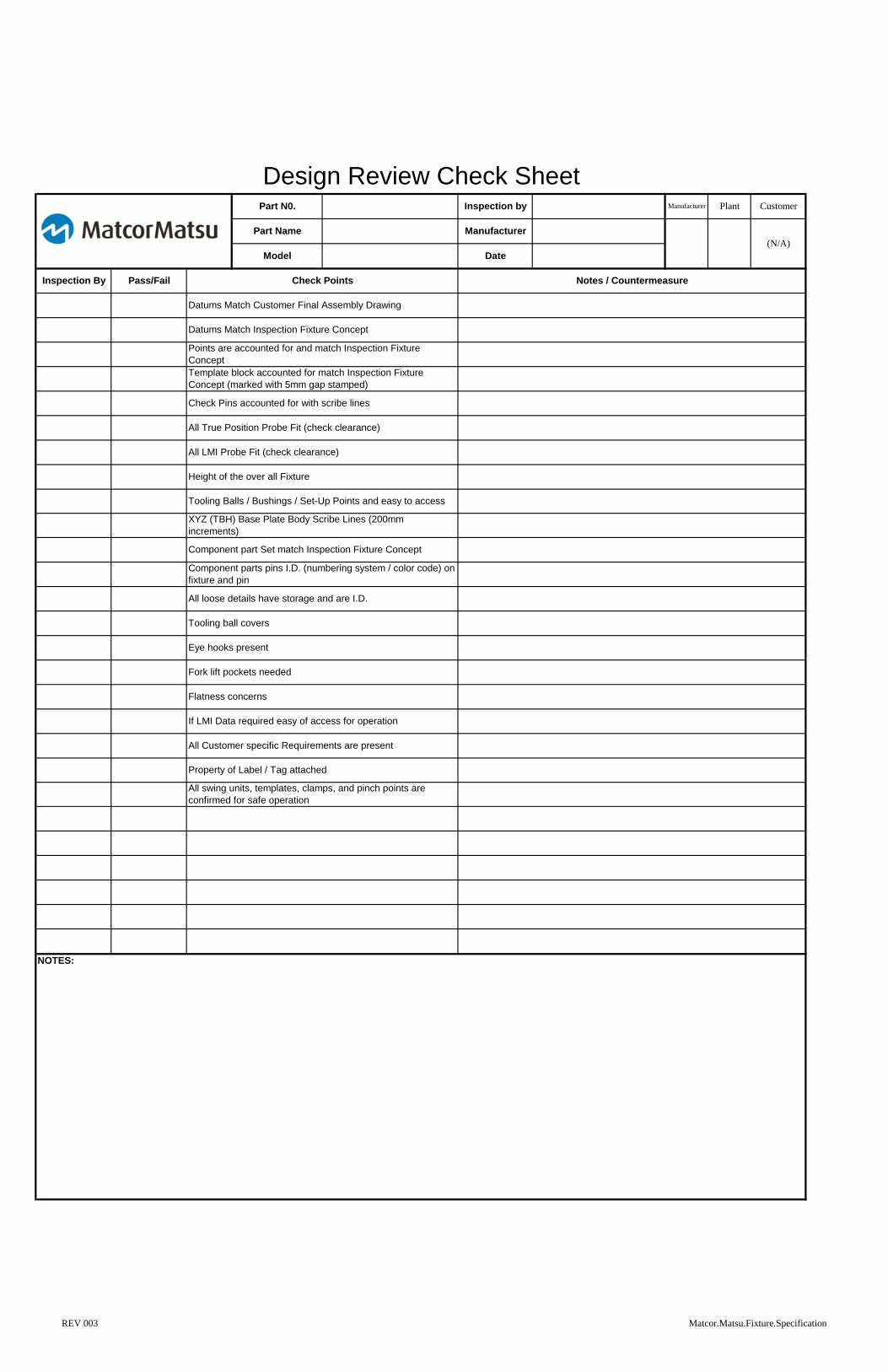
NOTES:
All swing units, templates, clamps, and pinch points are
confirmed for safe operation
All Customer specific Requirements are present
Property of Label / Tag attached
Flatness concerns
If LMI Data required easy of access for operation
Eye hooks present
Fork lift pockets needed
All loose details have storage and are I.D.
Tooling ball covers
Component parts pins I.D. (numbering system / color code) on
fixture and pin
Tooling Balls / Bushings / Set-Up Points and easy to access
XYZ (TBH) Base Plate Body Scribe Lines (200mm
increments)
All LMI Probe Fit (check clearance)
Height of the over all Fixture
Component part Set match Inspection Fixture Concept
Check Pins accounted for with scribe lines
All True Position Probe Fit (check clearance)
Points are accounted for and match Inspection Fixture
Concept
Template block accounted for match Inspection Fixture
Concept (marked with 5mm gap stamped)
Datums Match Customer Final Assembly Drawing
Datums Match Inspection Fixture Concept
Model Date
Inspection By Pass/Fail Check Points Notes / Countermeasure
Manufacturer
(N/A)
Design Review Check SheetPart N0. Inspection by Manufacturer Plant Customer
Part Name
REV 003 Matcor.Matsu.Fixture.Specification

NOTES:
Inspection Fixture Buy Off Check ListPart N0. Inspection by Customer
Datums Match Customer Final Assembly Drawing
Inspection By Pass/Fail Check Points Notes / Countermeasure
Manufacturer
Part Name Manufacturer
Date
Plant
Model
(N/A)
Check Pins accounted for with scribe lines
Template block accounted for match Inspection Fixture
Concept (marked with 5mm gap stamped)
Datums Match Inspection Fixture Concept
CMM Cert Data required at buy-off and all points within spec
Clear list of open items and closure dates if applicable
Points are accounted for and match Inspection Fixture
Concept
Check the Reference Plate for the right information
Part No#
All LMI Probe Fit (check clearance)
All True Position Probe Fit (check clearance)
Mobility of the Inspection Fixture
Weight Information
Check the Reference Plate for the right information
D/C Leave and Seriel #
Check the Property of '…"Plate for the right information
Customer Name
Pin up the component parts (if are available)
Check the Reference Plate for the right information
Part Name
Component part Set match Inspection Fixture Concept
XYZ (TBH) Base Plate Body Scribe Lines (200mm
increments)
Tooling Balls / Bushings / Set-Up Points and easy to access
Height of the over all Fixture
Component parts pins I.D. (numbering system / color code) on
fixture and pin
Eye hooks present
Gage R completed
Certification Data both end's of the tooling ball correct vector
(completed)
All loose details have storage and are I.D.
"Safety" No pinch points between any clamps or moveable
details
Fork lift pockets are present
Inspection Fixture has been confirmed base for flatness in its
nature state
All swing units, templates, clamps, and pinch points are
confirmed for safe operation
Fixture has a cart and is functional
REV 003 Matcor.Matsu.Fixture.Specification

1.
2.
3. All Fixtures over 50 pounds must have a cart. The cart must be included in the quote.
4.
EXAMPLE #1:
5.
EXAMPLE #2:
6.
EXAMPLE #3:
7. Inspection fixture instructions must be attached to the base plate.
*D/C Levels must be updated with fixture build so it is current when shipped.
Company
Standard
Design Changes should be tracked during the manufacturing of the inspection fixture. It is possible that a
D/C could occur during the manufacturing process. Included on each inspection fixture should be a
reference plate (Shown in the example below.) The plate should be attach to the base by (rivet or
screw).
GENERAL INFORMATION
MM will provide the fixture manufacturer with nominal locations for the check points. Any areas that can
not be checked because of interferences or any other issues must be discussed with MM before
manufacturing the inspection fixture.
Inspection fixture base height from the floor should have a max working height of about 1600mm. Height
should be developed with ergonomics as a priority. It should be considered how far will the part have to
be lifted to be set into the inspection fixture and how low the person inspecting the part will have to set to
the floor to collect the data.
All fixture heights will be reviewed by Plant Quality at design review/buy off.
All MM
Automotive
Group
Inspection fixtures should be designed according to the inspection fixture concept, (Page 4). A concept
will indicates the location on the datum nets, inspection fixture check locations, feeler checks, component
part set up locations or any other characteristic that needs to be called out for designing the inspection
fixture. The Customer Specific Requirements related to Check Fixture Specifications to be
considered as the primary guidance unless otherwise specified in the MM Automotive Group
quote. All clamps and details shal be free of any " pinch points" that could result in a safety
concern. Fixture maintenance is the resposibility of the suppplying plant for program life.
Fixtures are customer owned and must be appropriately protected from excessive environmental
conditions.
6-inch rubber casters (wheels) should be used unless otherwise specified. Two wheels should turn to
allow the fixture to turn easier. All wheels should lock down to prevent the fixture from moving while it
is in a stationary position. (see Example #1)
Ability to Rotate With lock down
Non-Rotating WheelsWith lock down
Base
1600mm Maximum Height
Part Set Height
Working Height
MANUFACTURER NAME:
PART NO#
PART NAME:
FIXTURE LENGTH SIZE MM
FIXTURE WIDTHSIZE MM
FIXTURE HEIGHTSIZE MM
TOTAL WEIGHT INCL. CART:MANUFACTURED DATE:
REVISION RECORD: DATE:
IF. CONCEPT LEVEL:
FIXTURE I.D.#:
KG
DESIGN LEVEL:
FIXTURE WEIGHT:
KG
PROPERTY OF:
REV 003 Matcor.Matsu.Fixture.Specification

8.
9.
10. Forklift pockets for fixtures over 500 lbs will be required on the fixture itself, not the stand.
Stand must allow for access for forklift pick up, and deviate must be confirmed by the plant.
11
EXAMPLE #5
12
COMPONENT PART (STAMPING) INSPECTION FIXTURES
13
a
b Go/Nogo stab pins used for hole position
c All trim tolerances wih a GDT profile of 2.0 mm or less must have a feeler check. Feeler must be set at
10.0 mm nominal distance.
Component part trim Scribe lines, are assumed at 'MIN & MAX' for GDT Profiles greater than 2.0 mm
d Hole size to be confirmed by standard Go.NoGo pins
e Fixture concept will define feeler size based off facilities tolerance defined. Ball type are only used upon
special required.
f If critical SPC are required, they will be called out on the inspection fixture concept.
* Holder blocks or holding clips for all stab pins/feelers are to be standard features for each gauge.
* All fixture tolerances defined in this spec apply to component part fixtures also*
Whenever possible the component part datums are assumed RFS unless otherwise specified by
customer or in CF Concept.
Component part fixtures are to be assumed Aluminum, (Baseplate & part profile).
If the Plant would prefer, designed into their concept "pattern plank" type is still acceptable. (The purpose
to using this material is for cost down (machine time / labor). As for details: datums, pins, nets, etc. (all
wearing details) are required to be hardened steel. Under no circumstances should "Grey Fixture Plank"
be used. This is easily broken and wears quickly.
Component part fixture shall conform to all other standards defined within this standard.
If the Plank will be over 24 inches it shall be supported by a baseplate of reinforced aluminum.
GENERAL INFORMATION (CONT'D)
Company
Standard
Whenever possible the inspection fixture should be designed with the part set up in car position. Part set
up direction will be defined on the Inspection Fixture Concept. If in car is deviated from approval from
the OEM is required.
If the inspection is heavier than 50 pounds require swivel clevis type eyebolts at all four corners. In
addition the eyebolts must have the load capacity to lift the maximum weight of the inspection fixture plus
25%. If the fixture exceeds 500 lbs refer to # 10 below.
Each inspection fixture has a model specific color (as applicable). This specific color will be provided at
the time of kick off and the inspection fixture should be painted this color. This usually a Sherman
Williams color code no#.
Note: Only portions of the fixture require this color, base, riser, stand, not entire fixture, and definitely not
The comp inspection fixtures weighting under 20 pounds must have two metal handles so the
fixture can be easily carried. The comp inspection fixtures weighting between 20 and 50 pounds
must have four metal handles.
Carrying
REV 003 Matcor.Matsu.Fixture.Specification

Base sizes larger than 1500 mm x 1500 mm are to be steel. Base sizes smaller than 1500mm x 1500
mmare to be fabricated Aluminium or " Wolverine " style cast Aluminum. Bases under 300 mm x 300 mm
may be cast Aluminum or " Wolverine" style cast Aluminum. Bases under 300 mm x
300 mm may be cast Aluminum ( >25.4 mm thick). All Machined surfaces must be between
70 and 100 micro-inch finish.
500 mmx 500 mm bases or larger, base surface must extend 200 mm beyond details.
Less than 500 mm x 500 mm, base surface must extend 100 mm beyond details.
No details or loaded parts may extend past the base edges when in open or closed pos.
EXAMPLE #1:
Inspection Fixture Setup for CMM Verification
Option 1:
Three position tooling alignment balls are for set-up.
Tooling balls MUST have removable protective coverings to protect.EXAMPLE #2:
BASE PLATE INFORMATIONInspection fixture base plate flatness tolerance should be 0.1mm. The inspection fixture base design
should be designed in a way that prevents sagging so that the 0.1 tolerance can be achieved. For gages
with size over 25 inches the aluminum base must be reinforced. Base plates that do not meet these
requirements may be rejected from use.
Inspection fixture base plate flatness needs to be checked in its mass production state. Which would be
on its stand/cart, or with its removable feet attached.
Body scribe lines should be identified on the fixture base and should be shown every 200mm. Body lines
are defined using X/T,Y/B,Z/H coordinates (X/T,Y/B,Z/H). Please verify the assembly drawing to identify
what coordinates should be used. (MUST BE STAMPED INTO THE INSPECTION FIXTURE BASE.)
Base starting corner must be identified with all the axis identified ( eg. X/T=100, Y/B= 200, Z/H=300 )
Bodyline ID.
FIXTURE
Bodyline ID
200 B 400 B
- 600 T
- 800 T
500 H
Base
Side View
Tooling Ball CoverTop View
Tooling Balls
REV 003 Matcor.Matsu.Fixture.Specification

3. Inspection Fixture Setup for CMM Verification (Continued)
Option 2:
Three position tooling alignment 14mm bushings are for set-up. EXAMPLE #4:
4.
5
EXAMPLE #6:
Inspection fixtures can have the ability to remove the feet/wheels directly from the base to eliminate the
need for an addition cart. This type of fixture would remove the feet and be placed onto the CMM
machine for verification.
All MM
Automotive
Group
NOTE: Regardless of option used, all set up points must be put in a position that can be
reached by CMM or portable CMM arm, and TBH (XYZ) locations stamped on the base
plate.
Company
Standard
BASE PLATE INFORMATION (CONT'D)
All surfaces of the base plate, risers pins, etc. shall be rust proofed. If Aluminum determined to be used
be cautious of the 0.1mm flatness specification, (rust proofed not required on Aluminum).
Side View
Top View
14mm Bushings
14mm Bushings
Base Stand
Removable Feet
Net plates for setup
REV 003 Matcor.Matsu.Fixture.Specification

(INCLUDING COMPONENT PART SETUP, page 6)
1. All datum pins and datum blocks are to be hardened. HRc 52-56.
2.
3
4
Note: If the pitch of the comp is not complex, or the customer does not required variable data a simple
to control pitch to +/-0.3 would be having a stationary 2 way pin 0.6 undersize in desired direction.
5
6
EXAMPLE #2
Company
Standard
(Note: Stops should be added to prevent pinch points for safety reasons. Also no clamp should overhang
the base. If this occurs, provide a positional stop. Fixture base size should never be increased because
of clamp locations.)
GENERAL DATUM'S AND NETS INFORMATION
All primary location pins shall use MMC pin locators unless otherwise specified on the comp inspection
fixture concepts. RFS pin can be used only if the Plant approves or as per customer request.
Secondary datum pins in some cases will be mounted on a slide unit to allow for the tolerance pitch. This
slide unit should have the ability to pin at zero and also take LMI data to verify the pitch. If the
component/child part is the same that locates the primary and secondary datum's this may not apply.
The clamp should be mounted 90 degrees from the surface of material. A ball or swivel flat metal tip
should be used and the clamp should contact the center of the net surface. Rubber tips are not
acceptable. This should also lock into position. The clamp should be located at minimum 20 mm
distance from the fixture. All clamps to be numbered in sequence to the fixture instruction.
All MM
Automotive
Group
All nets are to be attached to the fixture by screw and removable if needed. All nets MUST have clamps.
Rubber tipped clamps ware not acceptable and will wear down.
For net surfaces MM will provide the manufacturer with the nominal location and net size on the
inspection fixture concept. Also to be specified if clamping will be used or not used. In most cases the net
surface is called out on the final assembly drawing. All nets need to be on the fixture with one set screw
90 degree
Net Surface
Ball Tip
Mounting location should be secured to the riser without movement. The attachment bolts should be large enough to hold clamp secure so it does not come loose.
Handle height should be considered in the closed position. If handle height is too great, it will be difficult to load parts.
REV 003 Matcor.Matsu.Fixture.Specification

7 Datum Pin and Net Location Tolerance, (Component, Assembly, & Car Set Stands)
Spring loaded RFS pins
"How to determine if the assembly fixture requires component part setup pins?"
A Rank Comp - (high complexity, high importance to body) "Yes, must have"
B Rank Comp - (med complexity, med importance to body) "Yes, but subject to plant discretion"
C&D Rank Comps - (low complexity, low importance to body) "Not required"
Comp Rank to be determined by customer or internal before quoting begins
Assume all plants require, although the plant concept can over turn if not required.
1.
2.
3.
4.
EXAMPLE #A: True Position Style
EXAMPLE #B: Slide and Lock Style
EXAMPLE #C: Net Block or Spacer Style
Company
Standard
DATUM & NETS TOLERANCES
All MM
Automotive
Group
Component part sets need to be stored in a plastic box. That is screwed to the base plate. With the
fixture comp number on the box. Example would be a (OtterBox 2500 or 3500 in black) There maybe
more then one box per fixture.
Component part set up location will be specified on the assembly inspection fixture concept. Component
part setup locaters can be any of the following styles unless otherwise specified on the Assembly
inspection fixture concept. Designer should choose applicable style.
Include a Road Map for component part set. With all component part set pins, nets, and blocks need be
to be I.D. so they can be matched to the correct with numbering system AND/OR color code.
All threaded pin need to be removable. They can not stay on the fixture. There is to be no threads on the
fixture, (on pin Only).
GENERAL COMPONENT PART SET PINS INFORMATION
Feature Shape Location Tolerance
Location (+-0.05), Pitch (+0.1)Net Surfaces Flat Surface Tol. (+-0.05)Datum Pin (non-RFS) Round / Tulip Style Location (+-0.05), Size -0.1, Pitch (+0.1)
Pin slides inside and screw down cap holds in place for component part set.
PB
-208
-1.2
5
MP
B
A -A
B
0
Slide Block: should slide and lock in and out of location.Locking Handle
5
0Removable Net Block
Location Set
Screw down Cap that holds the True Probe Pin in place. Threads
Set on True Probe Set Screw. (Could be used as component part Net if needed.
Threads
Screw down Cap sets component part in place.
Sets Hole location
Part Net
Magnet to hold net
Location (+-0.05), Pitch (+0.1)MMC Pins
REV 003 Matcor.Matsu.Fixture.Specification

1.
2.
3. As applicable any weldments require stress relieving.
4.
5.
6.
EXAMPLE #1
7.
EXAMPLE #2:
Company
Standard
Swing block pins and bushings must be made with hardened steel. HRc 45~50. Positive stop blocks and
any metal to metal contact points must have hardened steel at the points of contact to control excessive
wear. Rockwell HRc to be 45~50.
All LMI Probe Blocks are to be set for three-Axis, (T, B & H). (Unless otherwise indicated on the comp
inspection fixture concept) Blocks are to be mounted by using the two hard dowel holes and single
holding screw.
All LMI Probe Blocks are to be the PB-208-1.25 Model FROM LMI ONLY.
Blocks are to be set at 65.0mm.
The PB-208-1.25 LMI Probe block can be modified if clearance to part is insufficient. Modifications to
block needs to be approved by Quality.
FIXTURE BLOCKS, PROFILES, SPC POINTS, & PINS
Swing blocks are to be stable in the locked position. There should be absolutely no movement while in
the locked position. Swing blocks should also include a positive stop for set position, Pin should not hold
the weight of the swing block.
All MM
Automotive
Group
Swing arms weighing is excess of 10 lbs must be controlled by air or gas shock. This is a safely related
concern.
Swing blocks must be secure when placed into the upright position. This is a safety related concern.
Set screwneeds to beadded to preventring from rotating
Set screw to hold third Axis Screw from movement.
Directional Ring to be set to body line direction. (Straight RH/LH, Front/Back, or Up or Down)
Third Axis Set
Dowell
Set Screw
Dowell
PB
-208-1
.25
MP
CO
MP
ON
EN
TS
61
6-4
56
-57
45 B-
A -A
B
-T (-A)(A) +T
-B (B-)
+B
Ring Set Screw
B-
A -A
B
55mm
PB
-208-1
.25
10mm
65mm
If facility does not require TP
measurement, the fixture concept would
define exclusions
REV 003 Matcor.Matsu.Fixture.Specification

8.
9.
10.
11
EXAMPLE #5
If the plant requires variable data it is assumed that Zero blocks will be required on the fixture. Here are a
few examples: LMI True Position, LMI 241, and LMI 200.
Tooling aid is used to verify location of LMI 200 Bushing.
EXAMPLE #4
Company
Standard FIXTURE BLOCKS, PROFILES, SPC POINTS, & PINS
Probe Block needs to be placed in a position for enough clearance for the Datamyte gauges, Third Axis
measuring adaptor, and tooling aids. (Most interference problems are not with the True Position Probe,
but with the Tooling Aids and Third Axis tools).
LMI 200 Bushing is to be mounted by means of the designed holding bracket, or placed into template.
Locking nuts are to be used to lock the bushing into place. If locking nuts cannot be used, other ideas
need to be approved by MM.
All MM
Automotive
GroupMP PROBE
Probe Block
3rd Axis Set Point
65.0mm +/-0.01
LMI 200 Insert
3rd Axis
Certification Tooling Aid,
LMI 200-SB is used to measure surface location. This gage inserts into the LMI 200 Bushing.
8.9 DIA.
4.8
4.8
POSITION
31.0 mm
24.1
LMIM 200-S 1234
85.2
34.9
31.8
CORDNOMINAL REFERENCE
Lock Nut
31.0
LMI 200 Bushing Mounting
Part
±.015
±.01 REF
S#
1234
M#
04
5
9.5 DIA.
50.00
31.00 19.0
**
6mm DIA. TOOLING BALLS
(2 plc.'s)
+
True Position probes must include wireless and standard hard wire.
3rd axis set with LMI 200 probe
Clearance must be evaluated at Design for all:
LMI 200 probes must include wireless and standard hard wire clearance.
True Position
LMI 241
LMI 200
REV 003 Matcor.Matsu.Fixture.Specification

12a
EXAMPLE #5:
12b Flush check shall have a minimum of 30mm flush measurement surface.
13
IMPORTANT: STAY OUT OF RADIUS OF PART AND WELD POINTS.
EXAMPLE #6:
14 Dowel pins for holding accuracy of fixture blocks are to be set as followed:
EXAMPLE #7:
15. All stab pins must have bushings. Pins and Bushing to be hardened. HRc 45~50.
Company
Standard BLOCKS, PROFILES, SPC POINTS, & PINS (CONT'D)
LMI 200 inserted into surface profile template block.
NOTE: For gap requirements, refer to Assembly Inspection Fixture Concept.All MM
Automotive
Group
All LMI checkpoints are to be positioned to touch at center point of weld flange. If center point cannot be
checked, other location must be approved by MM.
Min. cut to surface wall thicknessof 3.0mm.
*Note
Part
*Note-Bushing should havetwo lock nuts to secure bushing.
Dowel pin locations to be outside of the Block Dowel pin locations to be inside of the Block
Base Base
BlockBlock
REV 003 Matcor.Matsu.Fixture.Specification

16.
18 Stab pins are to check position and surface. See example below. To check surface a feeler would be applied
around the large pin diameter. This is default unless determined otherwise by the plan fixture concept.
.
EXAMPLE #8:
17. Other methods of pin surface check are shown below and should only be used if the Plant
concept has requested.
EXAMPLE #9:
18. No details on the inspection fixture can have use shims to meet the required location tolerance.
19.
20
Note: Where drawing tolerances are less than 0.5mm range, standard gauge tolerance are to reduce
from 0.1mm to 0.05mm.
21
EXAMPLE #4
22 If the customer does not have any requirements for feeler gage color identification the following should
apply with the plant approval:
Blue +/- 1.0
Red +/-0.50
Green +/-0.25 (to be made with a larger diameter, so that the operator
cannot use the wrong feeler for the tighter tolerance areas).
Gap standard should be indicated on areas that are designed with a controlled gap. Use the symbol (See
example below) to indicate a gap check area. See Inspection Fixture Concept for proper gap. These
must be stamped onto the fixture. Stick on labels or decals are not acceptable. These features could
also be scribed permanently as well.
NOTE: Tolerance bands below 1.0mm require a 3mm Gap, above 1.0mm are to be 6mm Gap
Company
Standard BLOCKS, PROFILES, SPC POINTS, & PINS (CONT'D)
All MM
Automotive
Group
All pins, nets or any other loose items on the inspection fixture should be provide with a toolbox mounted
on the inspection base, or be tethered to the fixture. These items should be color coated and I.D.
stamped in some way so it can be easily identified the placement location.
Note: If tethered a swivel to each end should be attached to prevent binding or kinking. A storage hole
or area should also be provided.
17 Feeler gauges must have a machined dimple painted to match the surface/trim location and stamped an
unique ID in alpha/numeric character (second option of colored tethers to match the profile should only
be used if the plant approves).
33
FEATURE SHAPE LOCATION TOLERANCESurface Templates
Stab Pins
True-Position Blocks
LMI / SPC port
LMI 241 Block
Component part Set Pins
Surface Profile Location (+-0.1)
Location (+-0.1)Location (+-0.1)(X,Y,Z)(T,B,H)
Check location (+-0.1)(position location +-0.2)
Check location (+-0.1)(position location +-0.2)
Location (+-0.1)
FEATURE SHAPE LOCATION TOLERANCE
Trim feeler
Surface feeler
5 (6)mm Gap
3mm Gap
"Zero" Gap
Surface Profile Location (+-0.1)
Location (+-0.1)Surface Profile
0
3
6 Surface Profile
Surface Profile
Surface Profile
Standard Trim and surface profile are 3mm
Special request as per Fixture Concept
Special request as per Fixture
0 3 5
5
6
REV 003 Matcor.Matsu.Fixture.Specification
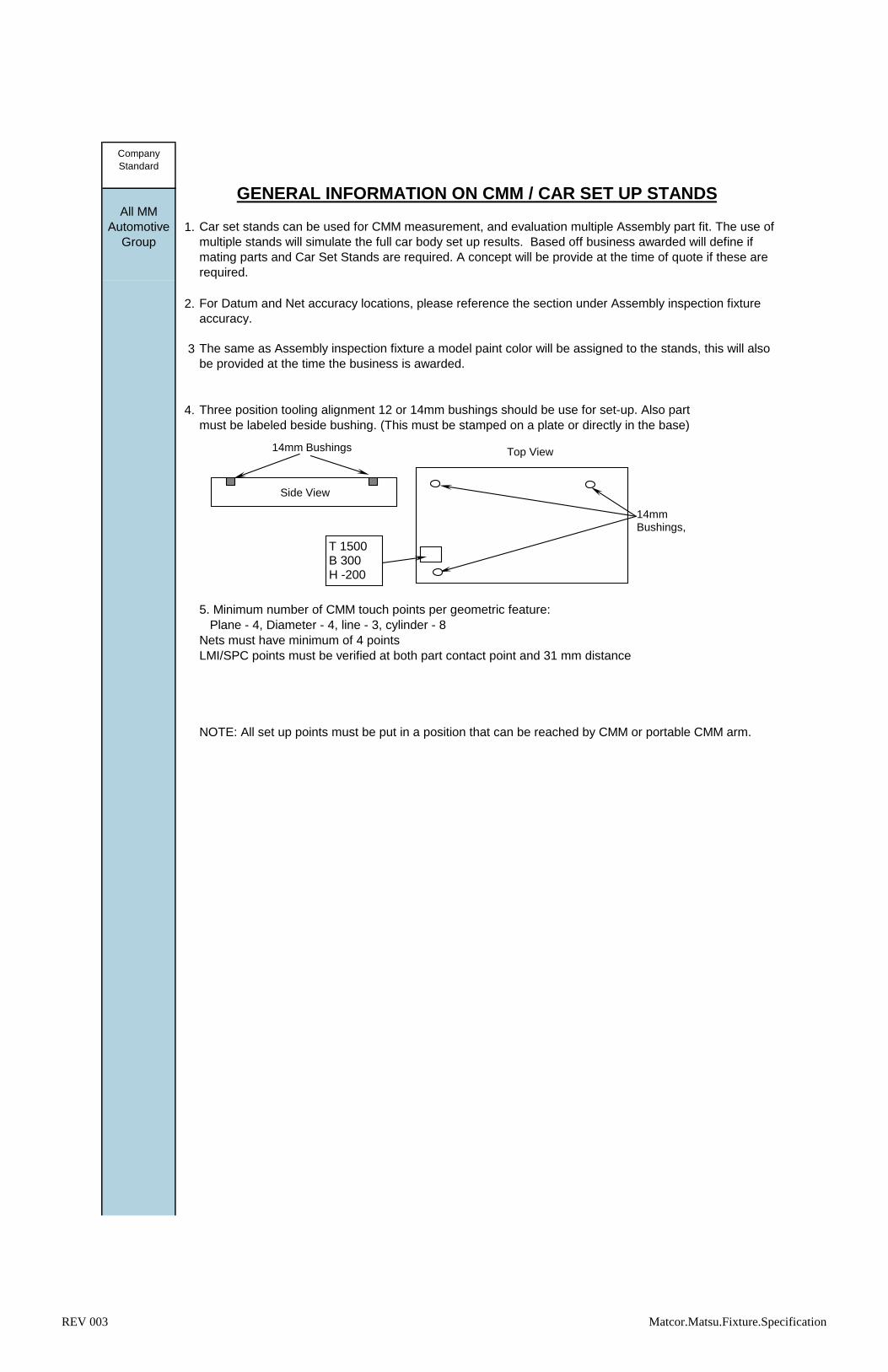
1.
2. For Datum and Net accuracy locations, please reference the section under Assembly inspection fixture
accuracy.
3
4. Three position tooling alignment 12 or 14mm bushings should be use for set-up. Also part
coordinateness numbers must be labeled beside bushing. (This must be stamped on a plate or directly in the base)
5. Minimum number of CMM touch points per geometric feature:
Plane - 4, Diameter - 4, line - 3, cylinder - 8
Nets must have minimum of 4 points
LMI/SPC points must be verified at both part contact point and 31 mm distance
NOTE: All set up points must be put in a position that can be reached by CMM or portable CMM arm.
Company
Standard
GENERAL INFORMATION ON CMM / CAR SET UP STANDS
Car set stands can be used for CMM measurement, and evaluation multiple Assembly part fit. The use of
multiple stands will simulate the full car body set up results. Based off business awarded will define if
mating parts and Car Set Stands are required. A concept will be provide at the time of quote if these are
required.
The same as Assembly inspection fixture a model paint color will be assigned to the stands, this will also
be provided at the time the business is awarded.
All MM
Automotive
Group
Side View
Top View
14mm Bushings,
14mm Bushings
T 1500B 300H -200
REV 003 Matcor.Matsu.Fixture.Specification

5.
Define
Facilities
Capabilities
Define
Facilities
Capabilities
See 2 Examples below for reference:
Option 1: Use L pins to locate the plates to the base/CMM table, and screw down pins to hold them
down, (L pins and Screws to be provided with the stands)
Option 2: Use Grid table set pin style, (Set pins to be provided with the stands).
Company
Standard
CMM / CAR SET UP STANDS DESIGN OPTIONSAll MM
Automotive
Group
EXAMPLE 1 OF CAR SET / CMM STANDS ON CAR SET TABLE.
SCREW DOWN PINS
L PINS, USED TO LOCATE ON TABLE AND CMM TABLE
STANDS SHOULD BE DESIGNED TO FIT ON THE TABLE AT THE SAME TIME. (CLEARANCE BETWEEN STANDS)
CMM Table Size: Center to Center on 10mm Channels: 250mm's
Top View of a CMM Holding Stand
Handles Only - No need for eye bolts or forklift pockets.
61
3
4
2
5
EXAMPLE 2 OF CAR SET / CMM STANDS ON CMM TABLE
Bottom View of a CMM Holding Stand
Side View of a CMM Holding Stand Pin - 3 per Stand. Hardened Steel Bushing insert for them.
7
8
10mm Hardened Steel Bushings - to hold bases off of CMM table 10mm's. Various amount used -depending on size of Base to support properly.
1. Aluminum Riser.2. Block to hold table pins.3. Attached wheels with brackets to allow stands to be raised up off of table and moved easily. Removable pins to hold in down position. #of wheels dependent on size of bases. (Over 60lb need wheels)4. Steel Hardened Alignment Bushings with TBH coordinates. 3 per stand.5. Steel Base.6. Label Plate.7. 8mm depth for pin insertion into CMM table. Add a 1mm, 45degree chamfer to bottom edge (red arrow).8. 20mm Diameter.
REV 003 Matcor.Matsu.Fixture.Specification

STEPS IN THE DESIGN, BUILD, AND BUY OFF
STEP 1: MM Plants to issues a concept to the fixture manufacturer. The first issued drawing,
so you can except several updates before a final maker layout will be established.
(Note: It is MM policy to have a minimum of 3 fixture manufacturers quote, so please submit your best
price.) However price is not always the final decision in deciding maker layout. Past experiences play a
big role in deciding: Meeting completion targets, quality of the inspection fixture, and communication during
the manufacturing process. (Keeping track of the project status).
STEP 2: The final development dwg will be issued to MM, and the initial GO release for design. This
will be the final quote before the maker layout is set. You will be notified of the final status of your quote.
There will be no chance to re-quote a better price, so give your best quote.
STEP 3: Once the final quotes are received a tentative maker layout will be set. Each MM plant will define
which fixture maker receives award, and than the fixture manufacture will be notified.
STEP 4: Our customer will give MM final approval for design, than a sign PO will be sent to the
manufacturer to begin design. Once the design is completed, the fixture manufacturer must notify, and send
the design for approval. MM Plant is the only facility that can approve the design.
STEP 5: Once design approval is given, the manufacturer will be notified by email to proceed with the build
assembly, and verification of the fixture. Completion timing also will also be confirmed.
(NOTE: IF A DESIGN CHANGE IS ISSUED AFTER A GO HAS BEEN GIVEN FOR DESIGN OR
BUILD. PLEASE QUOTE CHANGES SEPARATELY IF THERE IS ANY COST IMPACT.)
Company
Standard
CONDUCTING BUSINESS WITH MatcorMatsu AUTOMOTIVE GROUP
All MM
Automotive
Group
STEP 6: The MM plant will visit the manufacturer for a buy off.
(For Assembly & Component parts), if parts are available in advance they will be brought to complete a part set in the
inspection fixture to confirm any Interference points, all checkpoints are accessible, datum's hold part constantly, manufacturer
to complete GRR, etc. If parts are not available at that time this must be completed asap as to set direction if open issues
occur prior to final buy-off.
REV 003 Matcor.Matsu.Fixture.Specification

1. Inspection Fixture verification data should include the following items
a) Inspection date
b) Inspectors name
c) Proof of lab ISO17025 accreditation
c) CMM inspection standards, measurement data, and error (Include Road Map)
(CMM print out can be used, but numbers must correlate with illustration.)
All location pins, True Position Block, LMI Bushing, holes, trim lines and mating surfaces must be verified.
d) The Inspection Fixture verification data needs to be in an order that makes sense, For Example:
e) Define Inspection equipment used on report
– Machine type
– Manufacturer
– Machine accuracy
– Last calibration date on machine
f) Gauge R data if applicable/available
2.
Fixture verification data listed above should also be delivered at this time also.
3.
4.
3 associates, 10parts, 10 time. 10% maximum tolerance error Acceptable
10-30% must be evaluated for improvement, and discussed with MM / OEM Customer.
MM will define the critical points for Gauge R and collect the data at the manufacturer.
5. In Preparation for Buy off, please review our check list requirements.
Gauge R&R must be completed before shipping the Inspection Fixture, (Manufacturer responsibility). If
no parts are available, the Gauge R will be completed at MM ASAP.
Note: The Manufacturer is responsible to achieve an acceptable GRR prior to full buy-off.
Requirements:
FIXTURE VERIFICATIONCompany
Standard
MM uses the top of the inspection fixture base and both alignment lines or tooling balls to check and
verify all important areas on the fixture. ALL PINS, FEATURES OR ANY OTHER ITEM USED TO
CHECK THE PART MUST BE WITHIN THE CMM/SET-UP POINTS.
Physical Fixture should be delivered by the manufacturer to MM after the shipping evaluation and buy-off
is completed. The catia data , drawing and instructions (soft copy and on the fixture) must be sent
1. Datums 2. True Positions block 3. LMI Bushings 4. Component Part Set Pins
5. Templates 6. Flatness of Base in nature state
All MM
Automotive
Group
REV 003 Matcor.Matsu.Fixture.Specification

1.
2.
3.
4.
5.
6.
7. Fixture maintenance is the responsibility of the supplying plant for the program life.
All fixtures shall be built to math data and GD&T
A detailed build schedule must be submitted after job is granted to Fixture maker.
A week by week follow up should be provided to MM.
All inspection fixtures, fixture concepts, and actual design of inspection fixtures need to be approved by
MM before the manufacturer can proceed with the building of the fixture.
Make sure all information on a concept drawing is clear.
Provide a break down on the quote. Example: design cost, build and assembly cost, verification cost,
shipping cost or if multiple models are being added at the same time, split the cost on these items also.
This will make it less time consuming when MM has to complete a tooling change sheet that is required
by our customer.
MANUFACTURING GUIDELINES
Note: Any unclear issues need to be clarified by MM before proceeding with building the fixture.
Carefully review items on modified inspection fixtures. Once quoted in most cases, this is the final cost. If
a mistake is made on the quote, because of missed items, this may be determined to be the
manufacturer's responsibility.
Please include shipping cost on the quote.
Company
Standard
QUOTING INSPECTION FIXTURES WITH MatcorMatsu AUTOMOTIVE GROUP
MM will provide the manufacturer with a inspection fixture concept. This will indicate the approximate size
of the part and all the check points on the inspection fixture.
MM will provide the manufacturer the timing when the inspection fixture will be needed. This should be
indicated on the quote.
All Fixtures over 50 pounds must have a cart. The cart must be included in the quote.
All MM
Automotive
Group
REV 003 Matcor.Matsu.Fixture.Specification

1. Design should be reviewed utilizing full 3D CAD data, 2D Drawings are not acceptable.
2.
3
4.
5.
6.
7.
8.
9.
10. All Datums need to be held with a set screw, or bolt. They should not be loose on the Fixture
11.
12. All True Positions block need to be from LMI not made in house
All True Positions block need to be Third Axis Set with set screw to held the third axis screw from
movement
Company
Standard
LESSONS LEARNED
Component part set ups are used on assembly and sub assembly inspection fixtures. This means MM
will assemble the component parts in the inspection fixture. In the past there has been many cases of
component part pins interfering with other parts or can not swing a block into location because of pin
interference. These items should be verified at during design.
Component part pins not holding the part tight to the net (Pin threads not long enough, pin bushing
bottoming out inside the screw bushing, or pin taper hitting on the net block to early to set the part are
some of the issues.
All MM
Automotive
Group
Swing arms to have stops to avoid injury to employees or fixture. Swing arms that are large not having
some kind of shock system to prevent large blocks from falling and causing injury to employees.
Block clearance concerns with True Position probes and Third Axis probe interfering with other blocks
when trying to be inserted into the true position check block. This need to be verified also during design.
Third axis screws missing after inspection fixture arrives, but third axis accuracy data is present on the
verification data. Must set third axis screws to correct location.
No road map to indicate where points on the inspection fixture verification data are check. This make the
recertification process that is required by our customer verify difficult. A illustration or reference to the
inspection fixture concept should be included in the verification data.
Forklift pockets too close or too far apart to be used. In some cases missing altogether.
SPC (LMI 200) checks or template blocks designed to the incorrect side of material. Nominal for design
side used when opposite design side is checked.
REV 003 Matcor.Matsu.Fixture.Specification
Related Documents