ES-F-LF880V The FEBCO MasterSeries LF880V Reduced Pressure Zone Assembly is specifically designed to protect against possible backpressure and backsiphonage conditions for high hazard [i.e., toxic] application in accordance with Local Governing Water Utility Code. This Backflow Assembly is primarily used on potable drink- ing water systems where Local Governing Code mandates pro- tection from non-potable quality water being pumped or siphoned back into the potable water system. The LF880V features Lead Free* construction to comply with low lead installation requirements. The Lead Free* Reduced Pressure Zone Assemblies shall comply with state codes and standards, where applicable, requiring reduced lead content. Features • Inline Serviceable Assembly • Horizontal “N-Pattern” Installations • Vertical-Up “Z-Pattern” Installations • No Special Tools Required for Servicing • Captured Modular Spring Assembly • Reversible & Replaceable Discs • Field Replaceable Seats • Ductile Iron Valve Body Design • Stainless Steel Check Components • Modular Pressure Differential Relief Valve • Repairable Pressure Differential Relief Valve • Clapper Check Assembly • Captured O-ring Design MasterSeries ® LF880V Reduced Pressure Zone Prevention Assemblies Size: 2 1 ⁄ 2" - 10" LEAD FREE * Job Name ––––––––––––––––––––––––––––––––––––––––––– Contractor –––––––––––––––––––––––––––––––––––––––––––– Job Location ––––––––––––––––––––––––––––––––––––––––– Approval ––––––––––––––––––––––––––––––––––––––––––––– Engineer ––––––––––––––––––––––––––––––––––––––––––––– Contractor’s P.O. No. ––––––––––––––––––––––––––––––––––– Approval ––––––––––––––––––––––––––––––––––––––––––––– Representative –––––––––––––––––––––––––––––––––––––––– FEBCO product specifications in U.S. customary units and metric are approximate and are provided for reference only. For precise measurements, please contact FEBCO Technical Service. FEBCO reserves the right to change or modify product design, construction, specifications, or materials with- out prior notice and without incurring any obligation to make such changes and modifications on FEBCO products previously or subsequently sold. Specifications The FEBCO MasterSeries LF880V Reduced Pressure Zone Assembly shall be installed on the potable water supply and at each point of cross-connection to protect against possible back- pressure and backsiphonage conditions for high hazard [i.e., toxic] applications. The assembly shall consist of a main line valve body composed of a pressure differential relief valve located in a zone between two (2) independently acting approved clapper style check modules with replaceable seats and disc rubbers. Servicing of the pressure differential relief valve and both check modules does not require any special tools; both check modules are accessed through independently top entry covers. This assembly shall be fitted with AWWA Compliant inlet/outlet resilient seated shutoff valves; when used on a Fire-Sprinkler application, the assembly shall be fitted with approved UL/FM inlet/outlet resilient seated shutoff valves and contain four (4) properly located resilient seated test cocks as specified by AWWA Standard C511. Flow and pressure loss performance parameters shall meet the requirements of AWWA Standard C511. MODEL 880V REDUCED PRESSURE ZONE ASSEMBLY (Shown in standard orientation) *The wetted surface of this product contacted by consumable water contains less than 0.25% of lead by weight. NOTICE Inquire with governing authorities for local installation requirements NOTICE The information contained herein is not intended to replace the full product installation and safety information available or the experience of a trained product installer. You are required to thoroughly read all installation instructions and product safety information before beginning the installation of this product.

Welcome message from author
This document is posted to help you gain knowledge. Please leave a comment to let me know what you think about it! Share it to your friends and learn new things together.
Transcript

ES-F-LF880V
The FEBCO MasterSeries LF880V Reduced Pressure Zone Assembly is specifically designed to protect against possible backpressure and backsiphonage conditions for high hazard [i.e., toxic] application in accordance with Local Governing Water Utility Code. This Backflow Assembly is primarily used on potable drink-ing water systems where Local Governing Code mandates pro-tection from non-potable quality water being pumped or siphoned back into the potable water system.
The LF880V features Lead Free* construction to comply with low lead installation requirements. The Lead Free* Reduced Pressure Zone Assemblies shall comply with state codes and standards, where applicable, requiring reduced lead content.
Features• Inline Serviceable Assembly
• Horizontal “N-Pattern” Installations
• Vertical-Up “Z-Pattern” Installations
• No Special Tools Required for Servicing
• Captured Modular Spring Assembly
• Reversible & Replaceable Discs
• Field Replaceable Seats
• Ductile Iron Valve Body Design
• Stainless Steel Check Components
• Modular Pressure Differential Relief Valve
• Repairable Pressure Differential Relief Valve
• Clapper Check Assembly
• Captured O-ring Design
MasterSeries® LF880VReduced Pressure Zone Prevention AssembliesSize: 21⁄2" - 10"
LEAD FREE*
Job Name ––––––––––––––––––––––––––––––––––––––––––– Contractor ––––––––––––––––––––––––––––––––––––––––––––
Job Location ––––––––––––––––––––––––––––––––––––––––– Approval –––––––––––––––––––––––––––––––––––––––––––––
Engineer ––––––––––––––––––––––––––––––––––––––––––––– Contractor’s P.O. No. –––––––––––––––––––––––––––––––––––
Approval ––––––––––––––––––––––––––––––––––––––––––––– Representative ––––––––––––––––––––––––––––––––––––––––
FEBCO product specifications in U.S. customary units and metric are approximate and are provided for reference only. For precise measurements, please contact FEBCO Technical Service. FEBCO reserves the right to change or modify product design, construction, specifications, or materials with-out prior notice and without incurring any obligation to make such changes and modifications on FEBCO products previously or subsequently sold.
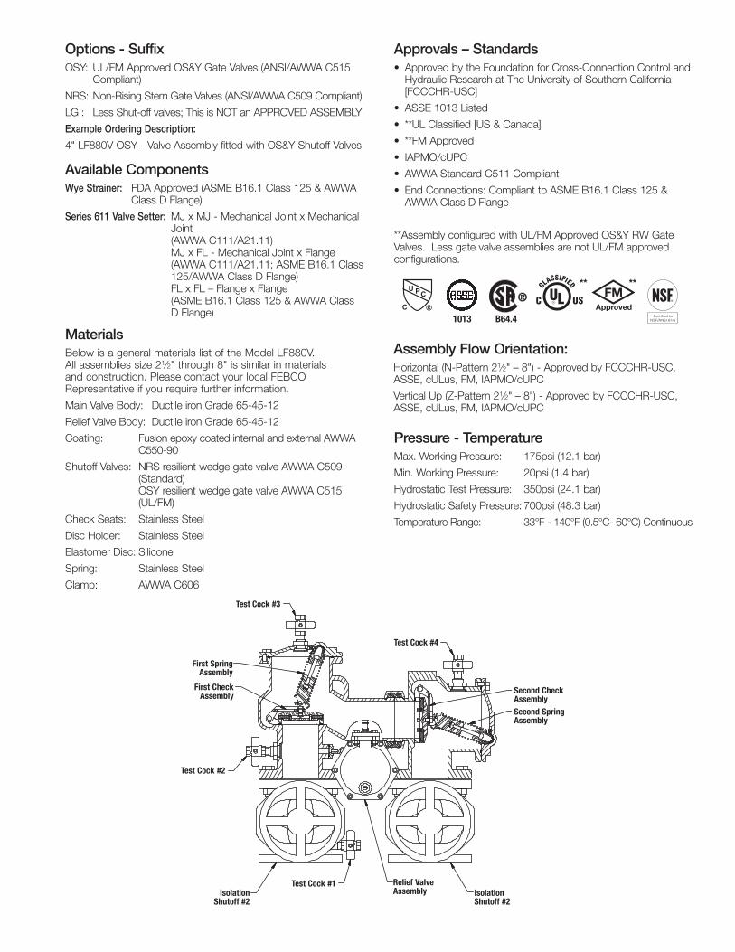
SpecificationsThe FEBCO MasterSeries LF880V Reduced Pressure Zone Assembly shall be installed on the potable water supply and at each point of cross-connection to protect against possible back-pressure and backsiphonage conditions for high hazard [i.e., toxic] applications. The assembly shall consist of a main line valve body composed of a pressure differential relief valve located in a zone between two (2) independently acting approved clapper style check modules with replaceable seats and disc rubbers. Servicing of the pressure differential relief valve and both check modules does not require any special tools; both check modules are accessed through independently top entry covers. This assembly shall be fitted with AWWA Compliant inlet/outlet resilient seated shutoff valves; when used on a Fire-Sprinkler application, the assembly shall be fitted with approved UL/FM inlet/outlet resilient seated shutoff valves and contain four (4) properly located resilient seated test cocks as specified by AWWA Standard C511. Flow and pressure loss performance parameters shall meet the requirements of AWWA Standard C511.
MODEL 880V REDUCED PRESSURE ZONE ASSEMBLY (Shown in standard orientation)
* The wetted surface of this product contacted by consumable water contains less than 0.25% of lead by weight.
NOTICEInquire with governing authorities for local installation requirements
NOTICEThe information contained herein is not intended to replace the full product installation and safety information available or the experience of a trained product installer. You are required to thoroughly read all installation instructions and product safety information before beginning the installation of this product.
Options - SuffixOSY: UL/FM Approved OS&Y Gate Valves (ANSI/AWWA C515 Compliant)
NRS: Non-Rising Stem Gate Valves (ANSI/AWWA C509 Compliant)
LG : Less Shut-off valves; This is NOT an APPROVED ASSEMBLY
Example Ordering Description:
4" LF880V-OSY - Valve Assembly fitted with OS&Y Shutoff Valves
Available ComponentsWye Strainer: FDA Approved (ASME B16.1 Class 125 & AWWA Class D Flange)
Series 611 Valve Setter: MJ x MJ - Mechanical Joint x Mechanical Joint (AWWA C111/A21.11) MJ x FL - Mechanical Joint x Flange (AWWA C111/A21.11; ASME B16.1 Class 125/AWWA Class D Flange) FL x FL – Flange x Flange (ASME B16.1 Class 125 & AWWA Class D Flange)
Pressure - TemperatureMax. Working Pressure: 175psi (12.1 bar)
Min. Working Pressure: 20psi (1.4 bar)
Hydrostatic Test Pressure: 350psi (24.1 bar)
Hydrostatic Safety Pressure: 700psi (48.3 bar)
Temperature Range: 33°F - 140°F (0.5°C- 60°C) Continuous
Assembly Flow Orientation:Horizontal (N-Pattern 21⁄2" – 8") - Approved by FCCCHR-USC, ASSE, cULus, FM, IAPMO/cUPC
Vertical Up (Z-Pattern 21⁄2" – 8") - Approved by FCCCHR-USC, ASSE, cULus, FM, IAPMO/cUPC
Test Cock #1
Test Cock #2
First SpringAssembly
Test Cock #3
Test Cock #4
Second SpringAssembly
Relief ValveAssembly
First CheckAssembly Second Check
Assembly
IsolationShut-off #1
IsolationShut-off #2
Test Cock #3
Test Cock #2
Test Cock #1IsolationShutoff #2
IsolationShutoff #2
Relief ValveAssembly
Test Cock #4
Second Spring Assembly
First Spring Assembly
First Check Assembly
Second Check Assembly
1013 B64.4
** **
Approvals – Standards• Approved by the Foundation for Cross-Connection Control and
Hydraulic Research at The University of Southern California [FCCCHR-USC]
• ASSE 1013 Listed
• **UL Classified [US & Canada]
• **FM Approved
• IAPMO/cUPC
• AWWA Standard C511 Compliant
• End Connections: Compliant to ASME B16.1 Class 125 & AWWA Class D Flange
**Assembly configured with UL/FM Approved OS&Y RW Gate Valves. Less gate valve assemblies are not UL/FM approved configurations.
MaterialsBelow is a general materials list of the Model LF880V. All assemblies size 21⁄2" through 8" is similar in materials and construction. Please contact your local FEBCO Representative if you require further information.
Main Valve Body: Ductile iron Grade 65-45-12
Relief Valve Body: Ductile iron Grade 65-45-12
Coating: Fusion epoxy coated internal and external AWWA C550-90
Shutoff Valves: NRS resilient wedge gate valve AWWA C509 (Standard) OSY resilient wedge gate valve AWWA C515 (UL/FM)
Check Seats: Stainless Steel
Disc Holder: Stainless Steel
Elastomer Disc: Silicone
Spring: Stainless Steel
Clamp: AWWA C606

Model LF880V Standard Orientation (N-Pattern)
Model LF880V Vertical Orientation (Z-Pattern)
Gate Valve Side View Relief Valve Detail Relief shipped on right side (shown) field reversible to left side.
4 15⁄16JL**
K*
3 1⁄2
F
G
AC B
D
E
F
IBA
CH
D
E
CL
Dimensions – WeightsSize: 21⁄2" - 10"
Below are the nominal dimensions and physical weights for the Model LF880V size 21⁄2" through 10". Allowances must be made for normal manufacturing tolerances. Please visit our website to download a copy of this product’s installation instructions, or contact your local FEBCO Representative for more information.
SIZE DIMENSIONS WEIGHT***
A B C D E F G H I J K* L** NRS OSY
in. in. mm in. mm in. mm in. mm in. mm in. mm in. mm in. mm in. mm in. mm in. mm in. mm lbs. kg. lbs. kg.
21⁄2 251⁄2 654 121⁄2 318 61⁄4 159 241⁄4 616 165⁄8 422 135⁄8 346 271⁄4 692 51⁄2 140 71⁄4 184 31⁄2 89 125⁄8 321 163⁄8 416 221 100 225 102
3 253⁄4 654 121⁄2 318 61⁄4 159 241⁄4 629 165⁄8 422 141⁄8 359 281⁄4 718 51⁄2 140 71⁄4 184 33⁄4 95 127⁄8 327 221⁄4 565 247 112 251 114
4 277⁄8 708 14 356 7 178 263⁄4 680 173⁄4 451 151⁄2 394 31 787 6 152 71⁄4 184 41⁄2 114 143⁄8 365 231⁄4 591 344 156 356 162
6 321⁄4 819 16 406 8 203 321⁄4 819 215⁄8 548 185⁄8 473 371⁄4 946 71⁄2 191 91⁄2 241 51⁄2 140 187⁄8 479 301⁄8 765 517 235 537 244
8 371⁄2 953 181⁄2 470 91⁄4 235 363⁄8 324 247⁄8 632 203⁄4 527 411⁄2 1054 83⁄4 222 101⁄4 260 63⁄4 172 231⁄2 597 373⁄4 959 808 366 836 379
10 421⁄16 1068 21 533 107⁄16 264 405⁄8 1032 271⁄2 699 2311⁄16 601 475⁄16 1202 93⁄8 238 1111⁄16 298 8 203 271⁄2 699 453⁄4 1162 - - 1344 610
Notes:* Indicates nominal dimensions with NRS Gate Valves** Indicates nominal dimensions with OSY Gate Valves (Full Open Position)*** Indicates weight of complete Backflow Assemblies with specified Gate ValvesThe gap drain is not designed to catch the maximum discharge possible from the relief valve. The installation of the FEBCO air gap with the drain line terminating above a floor drain will handle any normal discharge or nuisance spitting through the relief valve. However, floor drain size may need to be designed to prevent water damage caused by a catastrophic failure condition. Do not reduce the size of the drain line from the air gap fitting.

ES-F-LF880V 1813 © 2018 FEBCO
USA: Tel: (800) 767-1234 • Fax: (800) 788-4491 • FEBCOonline.comCanada: Tel: (905) 332-4090 • Fax: (905) 332-7068 • FEBCOonline.ca
Latin America: (52) 81-1001-8600 • FEBCOonline.com
PerformanceFlow capacity chart identifies valve performance based upon rated water Velocity up to 20fps
• Maximum service flow rate is determined by maximum rated Velocity of 7.5fps.
• AWWA Manual M-22 [Appendix C] recommends that the maximum water Velocity in the services be not more than 10fps.
• UL flow rate is determined by typically rated Velocity of 15 feet/sec.
Standard Orientation(N-Pattern)
Flow Curve N
Vertical Orientation(Z-Pattern)
Flow Curve Z
Pipe Support (furnished by customer) for valve weight
only.
21⁄2" LF880V
3" LF880V
4" LF880V
6" LF880V
8" LF880V
10" LF880V
psi
22 20 18 16 14 12 10 8 6 4 2 0
psi
22 20 18 16 14 12 10 8 6 4 2 0
psi 18 16 14 12 10 8 6 4 2 0
psi 18 16 14 12 10 8 6 4 2 0
psi
18 16 14 12 10 8 6 4 2 0
0 25 50 75 100 125 150 175 200 225 250 275 300 325 350 gpm 284 568 852 1136 lpm 7.5 14.7 22.0 fps
0 50 100 150 200 250 300 350 400 450 500 gpm 379 757 1136 1514 lpm 7.5 14.5 22.0 fps
0 100 200 300 400 500 600 700 800 gpm 379 1136 1893 2650 lpm 7.5 12.8 19.1 fps
0 200 400 600 800 1000 1200 1400 1600 gpm 757 2271 3785 5300 lpm 7.5 11.4 17.0 fps
0 400 800 1200 1600 2000 2400 gpm 1514 3028 4543 6057 7571 9085 lpm 7.5 10.5 15.3 fps
Service Flow
Service Flow
Service Flow
Service Flow
Service Flow
Rated Flow
Rated Flow
Rated Flow
Rated Flow
Rated Flow
*UL Rated Flow
*UL Rated Flow
*UL Rated Flow
*UL Rated Flow
*UL Rated Flow
N-Pattern Z-PatternCapacity
PSI D
rop
(*Fric
tion
Loss
)PS
I Dro
p (*F
rictio
n Lo
ss)
PSI D
rop
(*Fric
tion
Loss
)
PSI D
rop
(*Fric
tion
Loss
)PS
I Dro
p (*F
rictio
n Lo
ss)
PSI D
rop
(*Fric
tion
Loss
)
10" LF880V
0
2
4
6
8
10
12
14
16
0 500 1000 1500 2000 2500 3000 3500
PS
I
GPM
880VVUVD(N) VUVU(Z) Service Flow Rated Flow UL Rated Flow
1,892 3,785 5,678 7,570 9,463 11,356 13,248 LPMFPS7.5 9.4 14.1
psi
16
14
12
10
8
6
4
2
0 0 500 1000 1500 2000 2500 3000 3500 gpm 1892 3785 5678 7570 9463 11356 13248 lpm 7.5 9.4 14.1 fps
Service Flow Rated Flow *UL Rated Flow
Related Documents