MASTER'S THESIS Performance Prediction of a Valved and Valveless Pulse-jet Engine Running on Alternative Fuel Johanna Åstrand 2014 Master of Science in Engineering Technology Space Engineering Luleå University of Technology Department of Computer Science, Electrical and Space Engineering

Welcome message from author
This document is posted to help you gain knowledge. Please leave a comment to let me know what you think about it! Share it to your friends and learn new things together.
Transcript
MASTER'S THESIS
Performance Prediction of a Valved andValveless Pulse-jet Engine Running on
Alternative Fuel
Johanna Åstrand2014
Master of Science in Engineering TechnologySpace Engineering
Luleå University of TechnologyDepartment of Computer Science, Electrical and Space Engineering
Master’s Thesis
Performance Prediction of a Valved and Valveless
Pulse-jet Engine Running on Alternative Fuel
JOHANNA ASTRAND
Master of Science Programme in Space EngineeringAerospace Engineering
Lulea University of TechnologyDepartment of Computer Science, Electrical and Space Engineering
Lulea, Sweden
Monash UniversityDepartment of Mechanical and Aerospace Engineering
Melbourne, Australia
October 21, 2014


- To Johan -3 March 2014
iii

Abstract
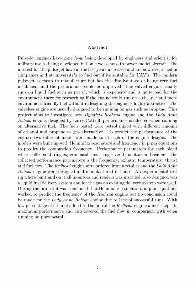
Pulse-jet engines have gone from being developed by engineers and scientist formilitary use to being developed in home workshops to power model aircraft. Theinterest for the pulse-jet have in the last years increased and are now researched incompanies and at university’s to find out if its suitable for UAV’s. The modernpulse-jet is cheap to manufacture but has the disadvantage of being very fuelinsufficient and the performance could be improved. The valved engine usuallyruns on liquid fuel such as petrol, which is expensive and is quite bad for theenvironment there for researching if the engine could run on a cheaper and moreenvironment friendly fuel without redesigning the engine is highly attractive. Thevalveless engine are usually designed to be running on gas such as propane. Thisproject aims to investigate how Dynajets Redhead engine and the Lady AnneBoleyn engine, designed by Larry Cottrill, performance is affected when runningon alternative fuel. The fuels tested were petrol mixed with different amountof ethanol and propane as gas alternative. To predict the performance of theengines two different model were made to fit each of the engine designs. Themodels were built up with Helmholtz resonators and frequency in pipes equationsto predict the combustion frequency. Performance parameters for each blendwhere collected during experimental runs using several monitors and readers. Thecollected performance parameters is the frequency, exhaust temperature, thrustand fuel flow. The Redhead engine were ordered from a retailer and the Lady AnneBoleyn engine were designed and manufactured in-house. An experimental testrig where built and on it all monitors and readers was installed, also designed wasa liquid fuel delivery system and for the gas an existing delivery system were used.During the project it was concluded that Helmholtz resonator and pipe equationsworked to predict the frequency of the Redhead engine but no conclusion couldbe made for the Lady Anne Boleyn engine due to lack of successful runs. Withlow percentage of ethanol added to the petrol the Redhead engine almost kept itsmaximum performance and also lowered the fuel flow in comparison with whenrunning on pure petrol.
v

Contents
1 Introduction 11.1 Pulse-jet History . . . . . . . . . . . . . . . . . . . . . . . . . . . . 21.2 Engine Theory . . . . . . . . . . . . . . . . . . . . . . . . . . . . . 2
1.2.1 Valved Pulse-jet . . . . . . . . . . . . . . . . . . . . . . . . 31.2.2 Valveless Pulse-jet . . . . . . . . . . . . . . . . . . . . . . . 3
1.3 Design Variations . . . . . . . . . . . . . . . . . . . . . . . . . . . . 41.3.1 In-line Systems . . . . . . . . . . . . . . . . . . . . . . . . . 41.3.2 Linear Systems . . . . . . . . . . . . . . . . . . . . . . . . . 51.3.3 U-shape Systems . . . . . . . . . . . . . . . . . . . . . . . . 51.3.4 Effects . . . . . . . . . . . . . . . . . . . . . . . . . . . . . . 6
1.4 The Project . . . . . . . . . . . . . . . . . . . . . . . . . . . . . . . 61.4.1 Project Definition . . . . . . . . . . . . . . . . . . . . . . . 61.4.2 Project Goals . . . . . . . . . . . . . . . . . . . . . . . . . . 71.4.3 Project Process . . . . . . . . . . . . . . . . . . . . . . . . . 7
2 Theory 82.1 Basic physical concepts . . . . . . . . . . . . . . . . . . . . . . . . 8
2.1.1 The Vena Contracta Effect . . . . . . . . . . . . . . . . . . 9
3 Method 113.1 Engine Design . . . . . . . . . . . . . . . . . . . . . . . . . . . . . . 11
3.1.1 Valveless . . . . . . . . . . . . . . . . . . . . . . . . . . . . 113.1.2 Valved . . . . . . . . . . . . . . . . . . . . . . . . . . . . . . 14
3.2 Ignition System . . . . . . . . . . . . . . . . . . . . . . . . . . . . . 153.3 Air Start-up System . . . . . . . . . . . . . . . . . . . . . . . . . . 163.4 Fuel System . . . . . . . . . . . . . . . . . . . . . . . . . . . . . . . 16
3.4.1 Liquid Fuel . . . . . . . . . . . . . . . . . . . . . . . . . . . 163.4.2 Gas Fuel . . . . . . . . . . . . . . . . . . . . . . . . . . . . . 173.4.3 Fuel mixtures . . . . . . . . . . . . . . . . . . . . . . . . . . 19
3.5 Measuring Instruments . . . . . . . . . . . . . . . . . . . . . . . . . 193.5.1 Load Cell . . . . . . . . . . . . . . . . . . . . . . . . . . . . 193.5.2 Microphone . . . . . . . . . . . . . . . . . . . . . . . . . . . 20
vii
3.5.3 Thermocouple . . . . . . . . . . . . . . . . . . . . . . . . . 213.6 Engine run procedure and data collection . . . . . . . . . . . . . . 22
3.6.1 Starting the engine . . . . . . . . . . . . . . . . . . . . . . . 223.6.2 Collecting data . . . . . . . . . . . . . . . . . . . . . . . . . 223.6.3 Engine shut down procedure . . . . . . . . . . . . . . . . . 22
3.7 Processing recorded data . . . . . . . . . . . . . . . . . . . . . . . . 223.7.1 Experimental data post-processing . . . . . . . . . . . . . . 223.7.2 Prediction model . . . . . . . . . . . . . . . . . . . . . . . . 23
4 Results 244.1 Valved Redhead Engine . . . . . . . . . . . . . . . . . . . . . . . . 24
4.1.1 Experimental results . . . . . . . . . . . . . . . . . . . . . . 244.1.2 Numerical results . . . . . . . . . . . . . . . . . . . . . . . . 31
4.2 Valveless Lady Anne Boleyn Engine . . . . . . . . . . . . . . . . . 32
5 Summary and Conclusions 34
6 Future Work 35
A Drawings 36
B MATLAB code 40
C Result tables 48
viii

Preface
This thesis is the final project for the Master of Science in Space Engineeringdegree focusing in Aerospace Engineering at the Department of Computer Sci-ence, Electrical and Space Engineering (SRT) at Lulea University of Technology(LTU). This project was conducted in Melbourne, Australia, at the Departmentof Mechanical and Aerospace Engineering at Monash University. The supervisorfor the project was Associate Professor Damon Honnery, Monash university. Theexaminer at LTU was Associate Professor Lars-Goran Westerberg.
I would like to thank A/Prof. Damon Honnery for the opportunity to conduct myproject at Monash University and for all the guidance and help he has given me.I want to give extra thanks to Edward Kuo for all the help at the lab and supportduring the project. A big thank to Juliann Pavlekovich-Smith for all the help onmy arrival to the university and for the help to finding accommodation for mylast weeks in Melbourne. Furthermore I would like to thank AngpannefreningensForskningsstiftelse, Sven Molin for all the help and Helen Fox at Monash HRImigration for helping me with my visa.
Finally, I would like to thank my family and friends for all their encourage-ment and support, its because of them that i have come this far. Special thanksto my mum Inga and Heinze for taking the long trip to Australia to visit me sowe could share some of the adventure.
Johanna AstrandMelbourne, Australia
ix

List of Figures
1.1 Marconnet’s valveless engine design.[2] . . . . . . . . . . . . . . . . 21.2 Cross-section of a valved pulse-jet engine. . . . . . . . . . . . . . . 31.3 Combustion cycle for a valveless pulse-jet engine[4]. . . . . . . . . . 41.4 Schubert in-line valveless pulse-jet design [5]. . . . . . . . . . . . . 51.5 Chinese CS valveless pulse-jet design[5]. . . . . . . . . . . . . . . . 51.6 Lockwood-Hiller U-shape pulse-jet engine [5]. . . . . . . . . . . . . 6
2.1 Streamline patterns for Vena contracta for two different intakes. . . 10
3.1 CAD image of the modified focussed wave engine called Lady AnneBoleyn. In the image it can be seen a hole to the left where thespark plug is to be mounted. . . . . . . . . . . . . . . . . . . . . . 12
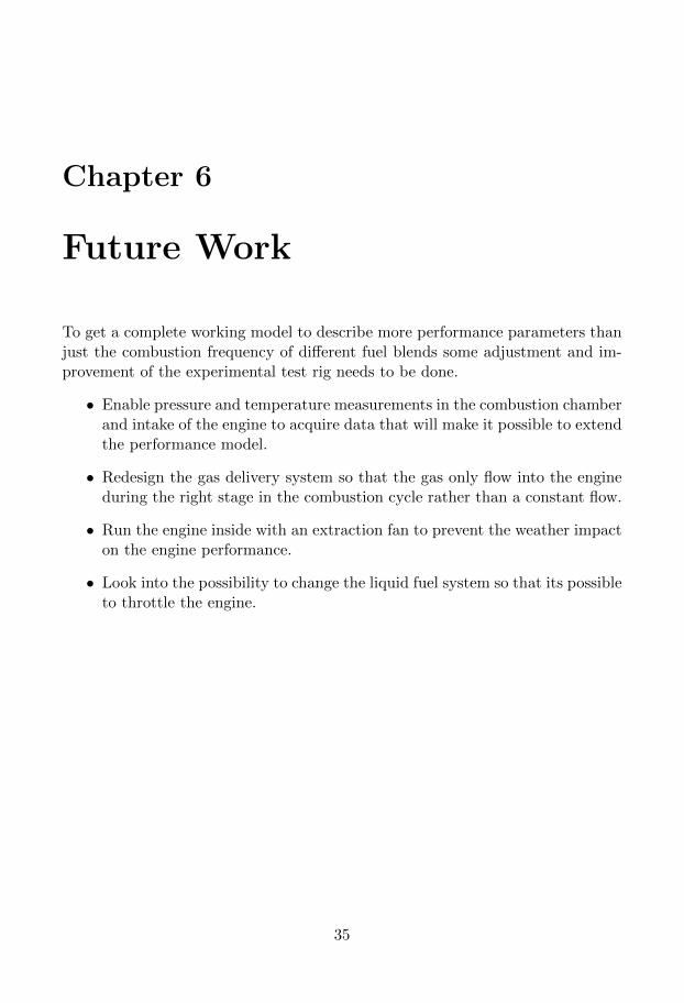
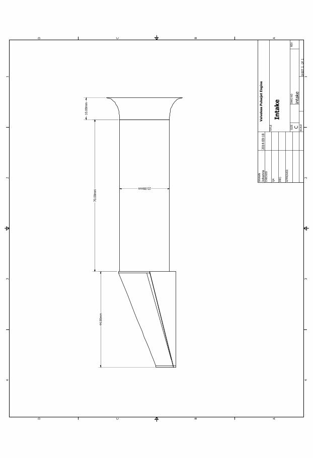
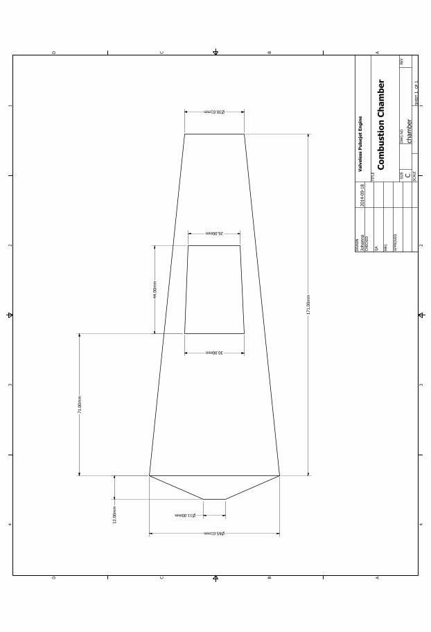
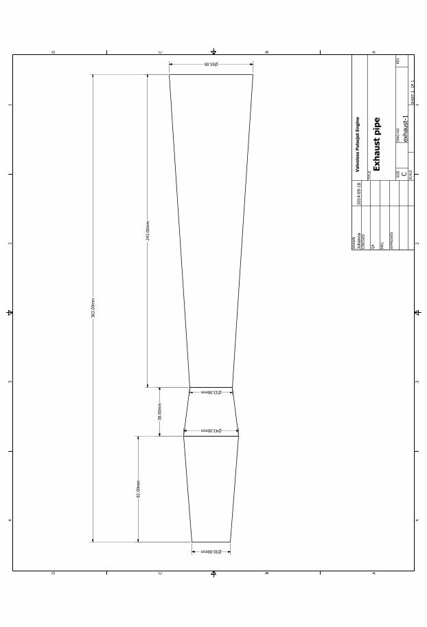
3.2 Combustion chamber with lid. . . . . . . . . . . . . . . . . . . . . . 133.3 Intake with flare etc. . . . . . . . . . . . . . . . . . . . . . . . . . . 133.4 Exhaust pipe designed as a divergent-convergent-divergent nozzle
to increase the gas flow velocity. . . . . . . . . . . . . . . . . . . . 143.5 Redhead pulse-jet engine with its typical red intake. . . . . . . . . 153.6 Engine intake with the fuel flow regulator with the fuel pipe con-
nected. . . . . . . . . . . . . . . . . . . . . . . . . . . . . . . . . . . 153.7 Liquid fuel system set-up . . . . . . . . . . . . . . . . . . . . . . . 173.8 Gas fuel system: 1. Solenoid valve, 2. Flow readers, 3. Switches
for ignition and power to valve and 4. Air and fuel regulators . . . 183.9 Set-up of the air and gas lines to the intake of the valveless engine. 183.10 Calibrations with known weights pulling in the load-cell . . . . . . 203.11 G.R.A.S 46BE 1/4” free-field microphone. . . . . . . . . . . . . . . 21
4.1 Fuel tank mass and thrust recordings from one run plotted againsteach other. . . . . . . . . . . . . . . . . . . . . . . . . . . . . . . . 25
4.2 Exhaust temperature for different fuel blends . . . . . . . . . . . . 264.3 Frequency peak to the left and two harmonic peaks to the right. . 274.4 Combustion frequency for different fuel blends . . . . . . . . . . . . 284.5 Close-up on recorded thrust data from the load-cell . . . . . . . . . 294.6 Average thrust for different fuel blends . . . . . . . . . . . . . . . . 30
xi

4.7 The fuel flow for three different fuel blends. . . . . . . . . . . . . . 314.8 Experimental recorded frequency and numerical frequency. . . . . . 32
xii

List of Tables
3.1 Dimensions of the manufactured valveless pulse-jet engine . . . . . 123.2 G.R.A.S 46BE features . . . . . . . . . . . . . . . . . . . . . . . . 21
4.1 Numerical prediction of combustion frequency for Valveless LadyAnne Boleyn Engine running on Propane . . . . . . . . . . . . . . 33
xiii
Nomenclature
Abbreviations
FAR Fuel-Air RatioFFT Fast Fourier TransformationFWE Focused Wave EngineLTRAC Laboratory for Turbulence Research in Aerospace and CombustionLTU Lulea University of TechnologySRT Department of Computer Science, Electrical and Space EngineeringUAV Unmanned Aerial VehiclesVTOL Vertical take-off and landing
Commonly used symbols
c Speed of sound [m/s]f Frequency [Hz]F Average thrust [N]γ Heat capacity ratio [-]L Length [m]m Air mass flow rate [kg/s]mf Fuel mass flow rate [kg/s]p Static pressure [Pa]R Specific gas constant [J/kgK]ρ Density [kg/m3]S Cross-section area [m2]T Temperature [K]V Combustion chamber volume [m3]
Indexes
burnt Burnt fuel/air mixturecold Cold fuel/air mixturee Exhausti Intakev Valved enginevl Valveless engine
Constants
γcold 1.4 -R 287 [J/kgK]Rg 290.9 [J/kgK]Vv 0.00031004 [m3]Vvl 0.00031920 [m3]
xiv

Chapter 1
Introduction
The first air breathing pulse-jet engine was invented in 1906 and from that timethe pulse-jet has change its shape and size several times. Today the pulse-jet isused in several areas such as military, industrial and hobby models. For militaryuse the engine mostly propels target drones but Boeing is talking about usingthe Pulse Ejector Thrust Augmentor (PETA) that is a new developed design ofthe pulse-jet engine to propel crafts in a vertical direction both for military andcommercial VTOL use [1].Th pulse-jet also appears in industrial usage like fog generators, industrial dryingand home heating equipment, but developers are trying to find more applicationssuch as biomass fuel conversion and boilers etc. Since a pulse-jet emits a lot ofheat when its running by effectively convert fuel to heat, makes it a interestingcandidate for heating applications. A study made at North Carolina Sate Uni-versity revealed that the valved engine where more sensible when lengthening theexhaust than the valveless engine [2]. Fei Zheng did a study for the same univer-sity on the effects of performance for pulse-jets when lengthening the intake andexhaust, but worked on a computational investigation to compare to the experi-mental results [3]. There has been a lot of investigation on the lengthening effectsbut no investigations how different fuels effects the engines. A pulse-jet enginehas a very simple design with few parts and is there for cheap by comparisonto manufacture and maintenance. Due to this the engine is commonly used byhobbiest that use it to propel their model air-crafts. Hobbiest tend to experimentwith the application areas for the pulse-jet as well, some have put it to propela bicycle, go-kart and boat. After the second world war the development of theengine started to decrease due to all effort was put on developing the turbo jetengine.The interest for the pulse-jet started to come back in the beginning of the newcentury, the main reason is because of the low production and propulsion costs.Now there is a lot of research to improve the designs to make them more efficientand reduce the noise levels, because the existing designs is not suitable to inte-
1
grate to commercial aircraft due to its high vibration and noise. Since UAV’s isnot disturbed by the high noise level the pulse-jet is a suitable propellent solution.One way to reduce the propulsion cost since the engines today is so fuel insuffi-cient is to change the fuel to a cheaper and more environment friendly mixture.To change the fuel mixture to a cheaper one is easy but to change it and maintainthe same performance is harder and needs to be researched on.
1.1 Pulse-jet History
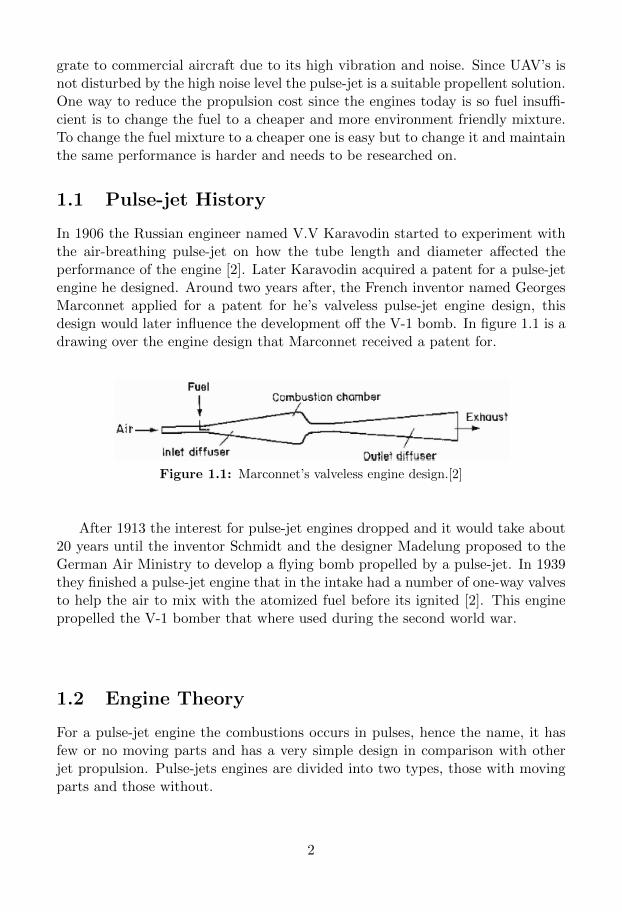
In 1906 the Russian engineer named V.V Karavodin started to experiment withthe air-breathing pulse-jet on how the tube length and diameter affected theperformance of the engine [2]. Later Karavodin acquired a patent for a pulse-jetengine he designed. Around two years after, the French inventor named GeorgesMarconnet applied for a patent for he’s valveless pulse-jet engine design, thisdesign would later influence the development off the V-1 bomb. In figure 1.1 is adrawing over the engine design that Marconnet received a patent for.
Figure 1.1: Marconnet’s valveless engine design.[2]
After 1913 the interest for pulse-jet engines dropped and it would take about20 years until the inventor Schmidt and the designer Madelung proposed to theGerman Air Ministry to develop a flying bomb propelled by a pulse-jet. In 1939they finished a pulse-jet engine that in the intake had a number of one-way valvesto help the air to mix with the atomized fuel before its ignited [2]. This enginepropelled the V-1 bomber that where used during the second world war.
1.2 Engine Theory
For a pulse-jet engine the combustions occurs in pulses, hence the name, it hasfew or no moving parts and has a very simple design in comparison with otherjet propulsion. Pulse-jets engines are divided into two types, those with movingparts and those without.
2
1.2.1 Valved Pulse-jet
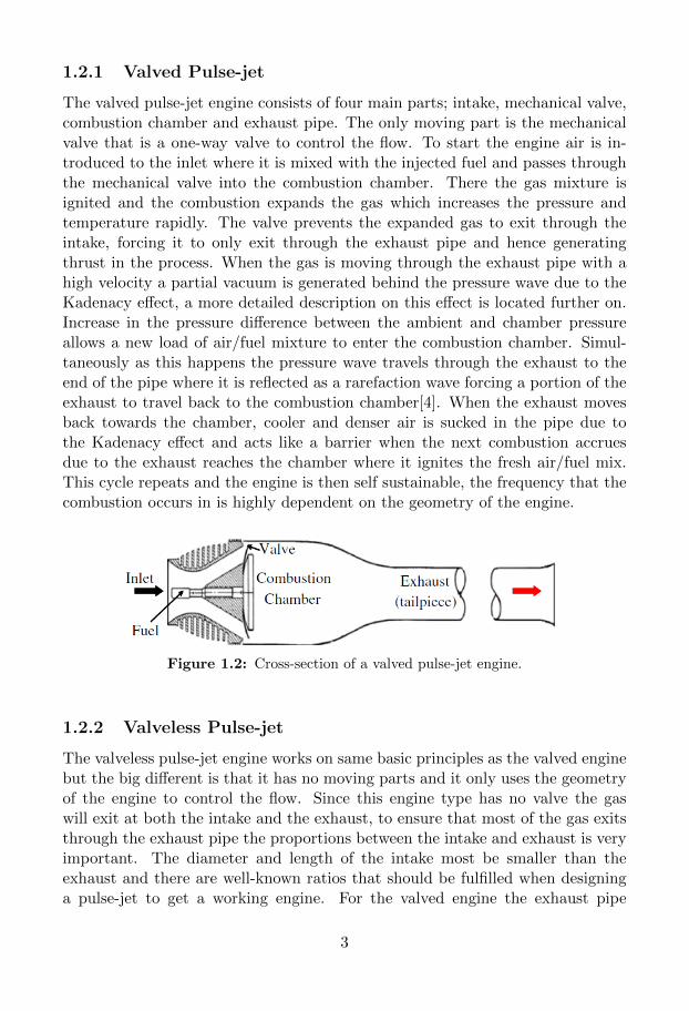
The valved pulse-jet engine consists of four main parts; intake, mechanical valve,combustion chamber and exhaust pipe. The only moving part is the mechanicalvalve that is a one-way valve to control the flow. To start the engine air is in-troduced to the inlet where it is mixed with the injected fuel and passes throughthe mechanical valve into the combustion chamber. There the gas mixture isignited and the combustion expands the gas which increases the pressure andtemperature rapidly. The valve prevents the expanded gas to exit through theintake, forcing it to only exit through the exhaust pipe and hence generatingthrust in the process. When the gas is moving through the exhaust pipe with ahigh velocity a partial vacuum is generated behind the pressure wave due to theKadenacy effect, a more detailed description on this effect is located further on.Increase in the pressure difference between the ambient and chamber pressureallows a new load of air/fuel mixture to enter the combustion chamber. Simul-taneously as this happens the pressure wave travels through the exhaust to theend of the pipe where it is reflected as a rarefaction wave forcing a portion of theexhaust to travel back to the combustion chamber[4]. When the exhaust movesback towards the chamber, cooler and denser air is sucked in the pipe due tothe Kadenacy effect and acts like a barrier when the next combustion accruesdue to the exhaust reaches the chamber where it ignites the fresh air/fuel mix.This cycle repeats and the engine is then self sustainable, the frequency that thecombustion occurs in is highly dependent on the geometry of the engine.
Figure 1.2: Cross-section of a valved pulse-jet engine.
1.2.2 Valveless Pulse-jet
The valveless pulse-jet engine works on same basic principles as the valved enginebut the big different is that it has no moving parts and it only uses the geometryof the engine to control the flow. Since this engine type has no valve the gaswill exit at both the intake and the exhaust, to ensure that most of the gas exitsthrough the exhaust pipe the proportions between the intake and exhaust is veryimportant. The diameter and length of the intake most be smaller than theexhaust and there are well-known ratios that should be fulfilled when designinga pulse-jet to get a working engine. For the valved engine the exhaust pipe
3
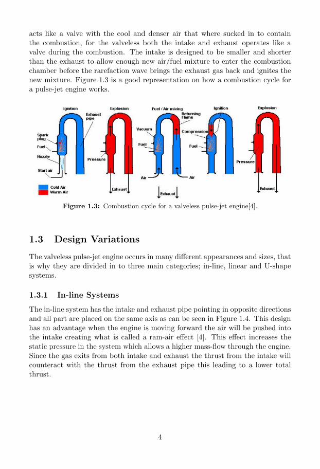
acts like a valve with the cool and denser air that where sucked in to containthe combustion, for the valveless both the intake and exhaust operates like avalve during the combustion. The intake is designed to be smaller and shorterthan the exhaust to allow enough new air/fuel mixture to enter the combustionchamber before the rarefaction wave brings the exhaust gas back and ignites thenew mixture. Figure 1.3 is a good representation on how a combustion cycle fora pulse-jet engine works.
Figure 1.3: Combustion cycle for a valveless pulse-jet engine[4].
1.3 Design Variations
The valveless pulse-jet engine occurs in many different appearances and sizes, thatis why they are divided in to three main categories; in-line, linear and U-shapesystems.
1.3.1 In-line Systems
The in-line system has the intake and exhaust pipe pointing in opposite directionsand all part are placed on the same axis as can be seen in Figure 1.4. This designhas an advantage when the engine is moving forward the air will be pushed intothe intake creating what is called a ram-air effect [4]. This effect increases thestatic pressure in the system which allows a higher mass-flow through the engine.Since the gas exits from both intake and exhaust the thrust from the intake willcounteract with the thrust from the exhaust pipe this leading to a lower totalthrust.
4

Figure 1.4: Schubert in-line valveless pulse-jet design [5].
1.3.2 Linear Systems
These engines has the same basic design approach as the in-line systems but thebig difference is that the intake is moved to the side of the combustion chamber,to ensure that the intake and exhaust pipes points in the same directions. Thisdesign takes away the disadvantage from the in-line systems where the thrust fromthe intake counteracts with the thrust from the exhaust pipe. The disadvantageswith this design are that the intake length is directly proportional to the exhaustlength and thereby makes it hard to optimise the performance of the engine andthe ram-air effect at the intake is lost [4].
Figure 1.5: Chinese CS valveless pulse-jet design[5].
1.3.3 U-shape Systems
This engine is shaped like a U, hence the name. This design is design to haveno sharp turns so that the flow trough the engine is smooth. This design hasthe same advantage as the linear design where the thrust generated at the intakeadds to the total thrust. The disadvantage with this design is first of that lostof the ram-effect and that this design takes up more space then the other two [5][6]. Image 1.6 shows the well known Lookwood design.
5
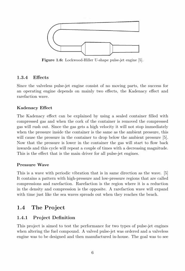
Figure 1.6: Lockwood-Hiller U-shape pulse-jet engine [5].
1.3.4 Effects
Since the valveless pulse-jet engine consist of no moving parts, the success foran operating engine depends on mainly two effects, the Kadenacy effect andrarefaction wave.
Kadenacy Effect
The Kadenacy effect can be explained by using a sealed container filled withcompressed gas and when the cork of the container is removed the compressedgas will rush out. Since the gas gets a high velocity it will not stop immediatelywhen the pressure inside the container is the same as the ambient pressure, thiswill cause the pressure in the container to drop below the ambient pressure [5].Now that the pressure is lower in the container the gas will start to flow backinwards and this cycle will repeat a couple of times with a decreasing magnitude.This is the effect that is the main driver for all pulse-jet engines.
Pressure Wave
This is a wave with periodic vibration that is in same direction as the wave. [5]It contains a pattern with high-pressure and low-pressure regions that are calledcompressions and rarefaction. Rarefaction is the region where it is a reductionin the density and compression is the opposite. A rarefaction wave will expandwith time just like the sea waves spreads out when they reaches the beach.
1.4 The Project
1.4.1 Project Definition
This project is aimed to test the performance for two types of pulse-jet engineswhen altering the fuel compound. A valved pulse-jet was ordered and a valvelessengine was to be designed and then manufactured in-house. The goal was to see
6
if the engines using alternate fuel are suitable to propel UAV’s and if its possibleto develop a model to predict the performance when running on alternative fuels.An experimental test table was also needed to be designed to enable measuringof the performance parameters.
1.4.2 Project Goals
• Research to find a design for a valveless pulse-jet engine that could bemanufactured in-house and that will generate an average thrust of 10N.Also order an valved engine that is factory-made that is close to the samesize as the valveless engine and generates nearly the same thrust.
• Successfully run both engines on alternate fuel mixtures.
• Build an operating thrust measurement set-up that constantly send datathough an output connected to a computer to get recorded.
• Make an operational experimental test table capable to measure the per-formance parameters of the engine, such as the exhaust temperature, com-bustion frequency and fuel flow rate.
• Make a theoretical model for both engines that calculates the combustionfrequency.
1.4.3 Project Process
The project was conducted in four different stages:
Stage 1Investigate existing research conducted in the field and gather knowledgeon the theory behind the engine process.
Stage 2Designing the valveless engine and create drawings for the manufacturingprocess. Build an experimental test rig to mount the engines and all mea-suring instrument on.
Stage 3The test phase, where all performance data are collected for each fuel blend.And build-up a frequency predictions model in MATLAB.
Stage 4Evaluate the collected data and compare it with the results from the pre-diction model.
7
Chapter 2
Theory
2.1 Basic physical concepts
Specific heat ratio for burnt air/fuel mixtures
After an air/fuel mixture has been burnt the specific heat ratio for that mixturewill change and the new is calculated through
γburnt = 4 ∗ 10−12 ∗ T e3 + 4 ∗ 10−9 ∗ T e
2 − 8 ∗ 10−5 ∗ Te + 1.3731. (2.1)
Here is Te the temperature at the exhaust of the engine.
Speed of sound
The speed of sound is given by
c =√γR∗T , (2.2)
where the R is the specific gas constant, T is the temperature of the gas/fluidand γ = Cp/Cv is specific heat ration for the gas/fluid.
Combustion frequency
To calculate the frequency at the inlet for both types of pulse-jet engines theHelmholtz resonator equation for short pipes is used:
fi =ci2π
√SiV Li
. (2.3)
Here S is the cross-section area, V is the volume of the combustion chamber, Lis the length of the inlet and c is as mentioned above the the speed of sound [3].The Helmholtz resonator is a container filled with gas with an open hole in oneof the ends and it applies when the wavelength of the sound is much longer than
8
the container dimensions. And a volume of air near the hole vibrates due to the”springiness” of the air inside.The inlet for a pulse-jet acts like a Helmholtz resonator since the combustionchamber acts like a spring and that the volume of the inlet is much smaller thanthe combustion chamber volume.
The exhaust frequency for a valveless pulse-jet engine can be calculated withthe Helmholtz resonator for a pipe with longer length given by
2πfeV
Secetan
(2πfeLe
ce
)= 1, (2.4)
where all the symbols represent the same as mentioned above[3].For a valved engine the exhaust frequency can be calculated as a sixth of a
wave in a tube according to
fe =c
6Le. (2.5)
Since the exhaust pipe can be seen as a pipe with one closed end and one openedthe frequency should be a quarter-wave but it was found during the project thata 1/6 wave were more accurate.
To get the total combustion frequency for the engine the mean value of theinlet and exhaust frequency is given by [3]
f =(fi + fe)
2. (2.6)
2.1.1 The Vena Contracta Effect
The shape of the inlet on a jet affects how big the vena effect is going to be andhence how effective the intake is to lead the air into the engine[4]. When air flowsinto a pipe the fluid streamlines is incapable to change its direction abruptly andthey will follow a smooth path around any sharp turn. The streamlines will thenconverge further down in the pipe and will narrow the flow in the pipe. Thelocation where the diameter of the flow is at its minimum that is called the venacontracta.
The coefficient of contraction is the ratio between the area of the flow at thevena contracta and the area of the intake. The highest value of the coefficient is1 and that means the vena effect is at its minimum, hence the lower value thestronger the effect [7]. The coefficient is obtained from the relation
Cc =AJ
Ah=
(dJdh
)2
, (2.7)
9

where Cc is the contraction coefficient, AJ is the area at the vena contracta andAh the area of the intake [7].
Figure 2.1: Streamline patterns for Vena contracta for two differentintakes.
Figure 2.1 illustrates two different intake designs, one with a sharp openingand one where the intake has a flare. For the flared intake the flow uses the entireintake pipe which can not be said for the one with a sharp opening.
10
Chapter 3
Method
3.1 Engine Design
The two engines that are used is close to the same size, which is between fifty andsixty centimetre long and they will generate almost the same amount of thrust,just to enable so that the same gear can be used and that a reasonable comparisonbetween the engines performance can be done.
3.1.1 Valveless
The valveless engine design called Lady Anne Boleyn was developed by LarryCottrill from an existing FWE engine design. This engine where picked to bemanufactured in-house after researching all available engine designs. Drawings ofthe engine is displayed in Appendix A. This design belongs to the linear systemsas described in chapter one and this type has its benefit that the intake andexhaust is directed in the same direction so that the combusted gas that exitingthrough the intake will add to the thrust. Having the intake and exhaust pointingin the same direction will also decrease the risk of injuries and damage to nearbyexperiment since its easier to point the exhaust to the exhaust-fan or put itoutside. A CAD image where created of the engine to get a 3D-visual of theengine before it was sent to be manufactured, the image can be seen in figure 3.1.
11
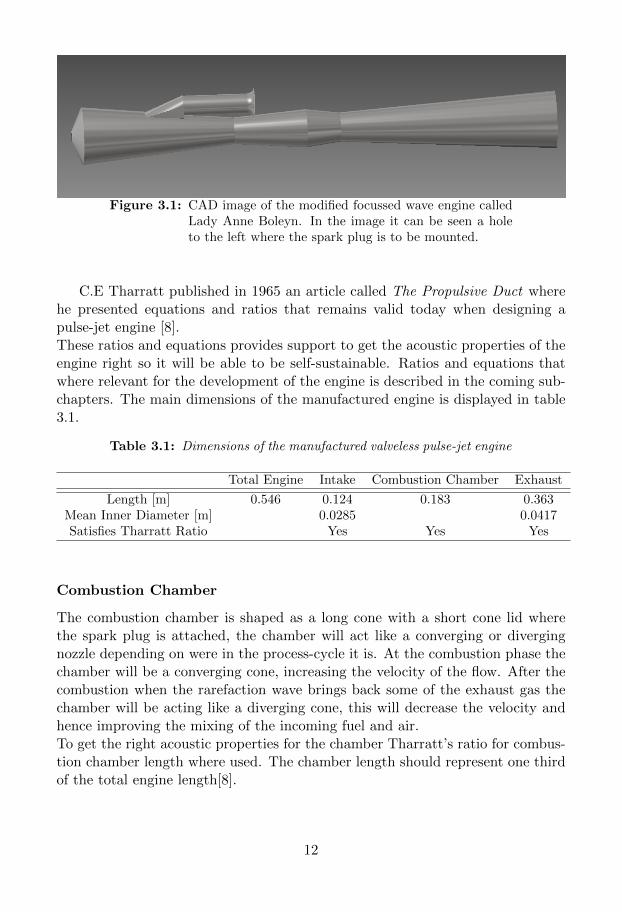
Figure 3.1: CAD image of the modified focussed wave engine calledLady Anne Boleyn. In the image it can be seen a holeto the left where the spark plug is to be mounted.
C.E Tharratt published in 1965 an article called The Propulsive Duct wherehe presented equations and ratios that remains valid today when designing apulse-jet engine [8].These ratios and equations provides support to get the acoustic properties of theengine right so it will be able to be self-sustainable. Ratios and equations thatwhere relevant for the development of the engine is described in the coming sub-chapters. The main dimensions of the manufactured engine is displayed in table3.1.
Table 3.1: Dimensions of the manufactured valveless pulse-jet engine
Total Engine Intake Combustion Chamber Exhaust
Length [m] 0.546 0.124 0.183 0.363Mean Inner Diameter [m] 0.0285 0.0417Satisfies Tharratt Ratio Yes Yes Yes
Combustion Chamber
The combustion chamber is shaped as a long cone with a short cone lid wherethe spark plug is attached, the chamber will act like a converging or divergingnozzle depending on were in the process-cycle it is. At the combustion phase thechamber will be a converging cone, increasing the velocity of the flow. After thecombustion when the rarefaction wave brings back some of the exhaust gas thechamber will be acting like a diverging cone, this will decrease the velocity andhence improving the mixing of the incoming fuel and air.To get the right acoustic properties for the chamber Tharratt’s ratio for combus-tion chamber length where used. The chamber length should represent one thirdof the total engine length[8].
12
Figure 3.2: Combustion chamber with lid.
Intake
The intake consists of three parts the coupling, pipe and flare. To get a goodsize of the intake area its inner diameter should be three quarters of the exhaustsmean inner diameter. For the length there is no useful ratio that can be used, soits necessary to experiment with different length ratios between the intake andexhaust to find what is working for that specific model. Since this project had astrict timetable there where no time for this so an existing engine designed wasused. Its crucial that the volume of the intake neither is to small or to big, sincethe cold air in the intake will act like a valve during the combustion stage and sothat the rarefaction wave makes it back to ignite the new batch of fresh air/fuelmixture.
Figure 3.3: Intake with flare etc.
The flare that is added to the intake is crucial to get a nice air flow in andout of the pipe, this is due to the vena contracta that where explained prior.
Exhaust
The exhaust is designed to be the type divergent-convergent-divergent and is themain modification from the basic engine design called Chinese CS. With thismodification on the exhaust pipe the average thrust is expected to be slightlyhigher than of a basic Chinese CS engine. To get the wanted shape the exhaust
13
is divided into three parts, the middle cone, choke cone and tail cone. The middlecone is the section directly connected to the combustion chamber and is shape asa divergent cone. The last two sections that is in the order convergent-divergentcan be called a de Lava nozzle. A de Lava nozzle is designs to increase the flowvelocity of the gas passing through it. This is explained by when the flow reachesthe converging cone the flow velocity has to increase due to the decreasing area,since the mass-flow has to be constant throughout the engine. When the gas thenreaches the divergent cone the velocity will increase a little more but both thepressure and temperature will rapidly decrease along the cone.
Figure 3.4: Exhaust pipe designed as a divergent-convergent-divergent nozzle to increase the gas flow velocity.
The first and second section main function is to rapidly increase the pressureof the gas before entering the final section of the exhaust.
3.1.2 Valved
The valved engine that was chosen was the Redhead from Dynajet, it is almostsame size as the valveless engine and will produce almost the same amount ofthrust, this was important so that the same test rig could be used for both engines.In figure 3.5 the Redhead engine is displayed and it can be seen that the sparkplug is mounted on the side of the combustion chamber. Also to be seen is thered intake with the slits that is to prevent the intake to get to hot during thetime the engine is running.
14
Figure 3.5: Redhead pulse-jet engine with its typical red intake.
To prevent the gas to exit out of the intake both during and after the combus-tion stage is finished the Redhead uses a solution where the chamber and intakeis separated by a thin plate with a number of holes place in a circle that is thencovered with an one-way reed valve. A cross-section image of the intake designwith valve set-up is located in chapter one in figure 1.2. The fuel pipe and start-up air is connected to the fuel flow regulator located at the center of the intake,the regulator will lead the fuel through the reed vale and into the combustionchamber when the start-up air is introduced. The start-up air is connected withan angle to the fuel that is mounted to have a strait way into the chamber as canbe seen in figure 3.6.
Figure 3.6: Engine intake with the fuel flow regulator with the fuelpipe connected.
3.2 Ignition System
Both engines has the same type of ignitions system where a spark plug is mountedand pressure sealed on the combustion chamber wall. Both spark plugs are ofstandard models and was powered by the same battery pack. The battery packused is a three celled rechargeable Li-Po pack that delivers 11.1 volt when fully
15
charged. It is specially design to have a high discharge rate to make it moresuitable for powering the spark plugs. The battery where connected to a controlbox equipped with a power switch to make it easy to turn the power on and off.
3.3 Air Start-up System
For the Redhead engine it was specified that the start-up air had to be deliveredwith a minimum pressure of 40 psi. And assumptions where drawn that thevalveless engine would need about the same as the Redhead. At first a bicyclepump where used that could give a burst of air at 40 psi, but it was later foundout that it was not an effective way to introduce the air. The better solutionwhere to use compressed air that was controlled by a air-gun. A modificationwhere made to the gun to improve the manipulation of the flow exiting fromthe gun, a piece of rubber hose where used between the tip of the gun and theconnection at the intake.
3.4 Fuel System
A pulse-jet engine can be powered by either gas or a liquid fuel but these twofuel forms need different delivery system to work. Since the valved engine wheredesigned to use liquid fuel and the valveless to run on gas, two different fuelsystem had to be made.
3.4.1 Liquid Fuel
The Fuel delivery system for liquid fuel was designed after the principal that thepressure differences between the combustion chamber and the fuel tank will suckas much fuel it need for each cycle with out any external help.For this to work the fuel level in the tank had to be lower than the center of theintake where the fuel tube is connected, this is to prevent the fuel from flowinginto the engine rather then to be sucked up at the right time. The tank wasmounted on a hight adjustable platform to make it easy to manage how muchfuel the engine gets.
16
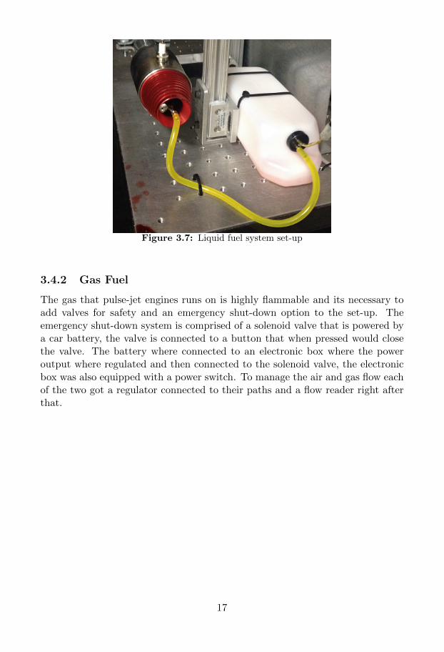
Figure 3.7: Liquid fuel system set-up
3.4.2 Gas Fuel
The gas that pulse-jet engines runs on is highly flammable and its necessary toadd valves for safety and an emergency shut-down option to the set-up. Theemergency shut-down system is comprised of a solenoid valve that is powered bya car battery, the valve is connected to a button that when pressed would closethe valve. The battery where connected to an electronic box where the poweroutput where regulated and then connected to the solenoid valve, the electronicbox was also equipped with a power switch. To manage the air and gas flow eachof the two got a regulator connected to their paths and a flow reader right afterthat.
17
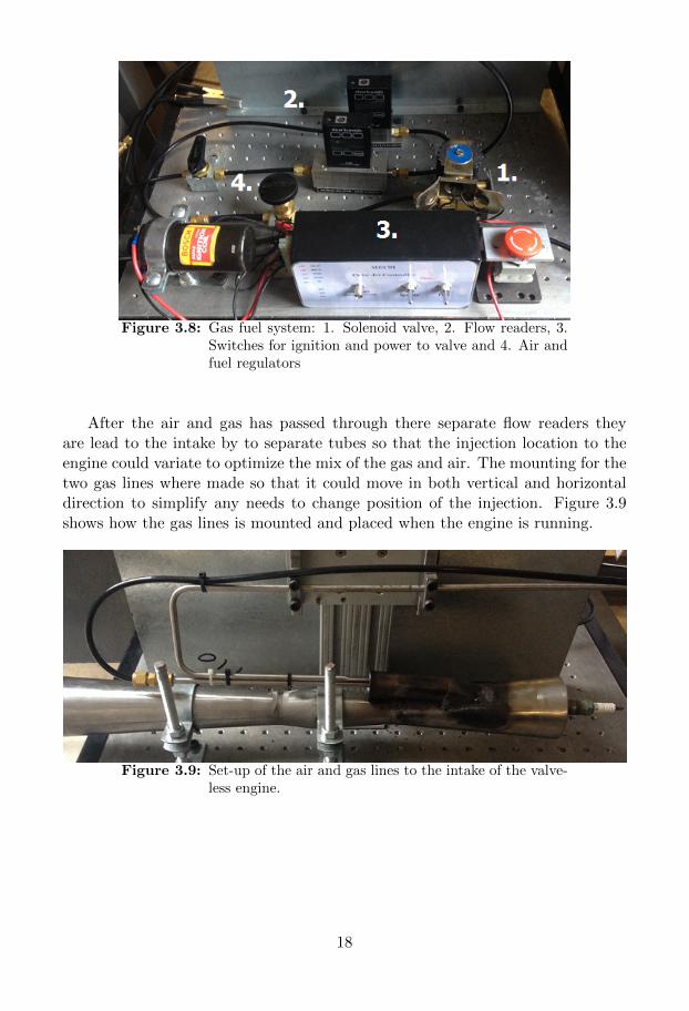
Figure 3.8: Gas fuel system: 1. Solenoid valve, 2. Flow readers, 3.Switches for ignition and power to valve and 4. Air andfuel regulators
After the air and gas has passed through there separate flow readers theyare lead to the intake by to separate tubes so that the injection location to theengine could variate to optimize the mix of the gas and air. The mounting for thetwo gas lines where made so that it could move in both vertical and horizontaldirection to simplify any needs to change position of the injection. Figure 3.9shows how the gas lines is mounted and placed when the engine is running.
Figure 3.9: Set-up of the air and gas lines to the intake of the valve-less engine.
18
3.4.3 Fuel mixtures
Propane
Propane were selected to be the fuel for the valveless engine since it has a lowboiling point and leaves little residue and smell after burning [9]. The gas lowboiling temperature is also beneficial since it will heat up the engine faster thatwill make the engine to start faster. Propane is even preferred for safety reasonssince its vapour dissipates fast in a room with open air.
Petrol and ethanol
The Redhead engine where designed to run on unleaded petrol which means thatthe best performance that the engine will have will be on petrol. So to have agood reference when trying different fuel blends it was decided to keep petrol asthe predominant fuel during mixing. The fuel that where to be mix with thepetrol had to satisfy a couple of requirements: Environment friendly, easy to findand reasonable price.
Ethanol did full-fill all the requirements and it has the advantage that the un-leaded petrol is already diluted with a small amount of ethanol by the retailer,so to avoid adding a third substance to the blend ethanol is the selected. Whenmixing ethanol and petrol the octane rating of the fuel is increased and it willsupport a higher compression ratio before self-combustion and higher octane rat-ing will help to a more complete fuel combustion. [10] [11] Ethanol will alsoreduce the harmful emissions residues from the combustion. It was decided thatthe petrol should be diluted with 5%, 10%, 20% and 30% ethanol.
3.5 Measuring Instruments
3.5.1 Load Cell
To measure the average thrust generated by the engines a single point load-cellby model PTASP6-N-5kg with a maximum thrust of 5 kg where used, since themaximum thrust expected from either engine was just below 2 kg. The load-cellwas connected to a indicator, model PT200MI Digital Indicator, with a 5 voltsoutput connected to a computer that would record the data it received. Bracketsto attach each engine to the load-cell and a mount to raise and attach the load-cellto the test-rig table where designed and then manufactured in-house.
Calibrations
The load-cell is calibrated when delivered but a control calibration was necessaryto perform with the entire set-up, since the load-cell is mounted of ground and
19
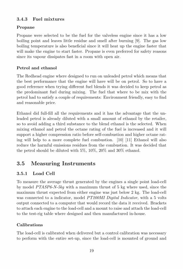
the engine is mounted on-top of the load-cell. The calibration was performed bybuilding a set-up with a wire strapped to the engine mount and den lead througha pulley and on the other end weights where hung. The calibration where doneover a weight span from 100 grams to 5 kg to ensure a good calibration.
Figure 3.10: Calibrations with known weights pulling in the load-cell
The output data from the indicator that is sent to the computer is in voltsfrom zero to five and during the calibrations a study where made and it wasconcluded that it was an linear relation where 0.5 volt represented 1 kg. Thiswhere later used to transform the recorded data from volts to kg.
3.5.2 Microphone
For measurement of the combustion frequency the G.R.A.S 46BE where used dueto its high cut-off value and its a free-field microphone designed for all acousticapplications when the microphone can be pointed directly at the source.
20

Table 3.2: G.R.A.S 46BE features
Frequency range 4 Hz to 80 kHzDynamic range 35 dBA to 160 dB
Sensitivity 4 mV/Pa
The microphone where mounted on the experimental test rig directly pointingat the exhaust opening of the engine, the distance between the microphone andexhaust opening is about three decimetres. The output where sent and recordedon a computer to be post-processed.
Figure 3.11: G.R.A.S 46BE 1/4” free-field microphone.
3.5.3 Thermocouple
A thermocouple where but at the centre of the exhaust outlet to measure theexiting gas, this temperature where later used in the MATLAB model to predictthe frequency. Thermocouples are commonly used over a large variation of areasdue to its simplicity and its price is reasonable. It consists of two dissimilarconductors that are in contact at one or several spots, when there is a temperaturedifference between one of the spots and the reference temperature it produces avoltage. The relation between the voltage and temperature is known for each alloythat can be used in a thermocouple and depending on the expected temperaturerange the best suited alloy thermocouple is used.
21
3.6 Engine run procedure and data collection
3.6.1 Starting the engine
All tests to measure the performance parameters for the different fuel blendsof each engine where conducted in the same way. First the engine test rig weremoved outside, then all sensors were connected to the computer and the LabVIEWSignalExpress program was started. Then the compressed air and fuel lines wereconnected to the engine. When time to start the engine the ignition were turnon and the start-up air were introduced. The air where applied in short burst(minimum 40 psi), at first the engine will pop a couple of times before its warmenough to start. When the engine starts running the air and ignition is turnedof and once it clear that the engine is self-sustainable the recording is started onthe computer.
3.6.2 Collecting data
First a couple of test were made for pure petrol to have for reference point thenseries of test were made for each blend. It started with 5% ethanol and thenincreasing the amount of ethanol in the blend until the engine would not run.Each blend were tested repeatedly for a set of times to provide a good collectionof data.The average thrust and frequency output were recorded in LabVIEW with asample rate of 10,000 Hz to get a good set of data.
3.6.3 Engine shut down procedure
To shut down the engine the fuel flow is throttled. When the engine has beenshut down it has to cool down before it can be run again due to the high risk ofdestroying the valve or welding on the engine.
3.7 Processing recorded data
3.7.1 Experimental data post-processing
As mentioned in section above, the sample rate were set to be 10,000 Hz and therecorded data were saved in a file that could be opened in Excel.
Load-cell output data
The output data that represent the average thrust from the load-cell is recorded asvoltage and were needed to be converted to kg. During the calibration of the load-cell is was noticed a relation between voltage and kg were 0.5 volt represented 1kg, this were used to convert the data in Excel. When the data had been converted
22
it was saved as a CVS-file and then plotted in MATLAB. The unprocessed datais also used to look at a consecutive sample of around 300 data points to comparethe recorded peaks where the combustion occurs to the frequency received fromthe FFT.
Microphone output data
The microphone’s output is in volt and the recorded data need to be processedbefore the frequency could be found. The recorded data is moved to a MATLABfile where it will go though a Fast Fourier Transformation and then plotted tofind the peak that represent the dominant frequency. The MATLAB code thatwhere made to preform the FFT is presented in Appendix B.
Thermocouple reading
The thermocouple where connected to a multimeter that were manually readwhen the engine were self-sustainable and had reached a state close to the steadystate. This was to get a good reference to the exhaust temperature when enginewas running steady, this where made the same way for all fuel blends.
3.7.2 Prediction model
Since the two engines has different designs, most important that one is equippedwith a valve and the other is not, is was necessary to make two different predic-tions models to calculate the frequency. The two prediction models where madein a MATLAB file with a section for each. The Helmholtz resonator for the ex-haust on the valved engine (equation 2.4) is an equation that need to be solvedfor fe, since it was complicated to find a solution an option was to find the firstzero-crossing for the curve. Since MATLAB do not have a suitable function forthis a pre-written code was used.[12]In the prediction models the exhaust temperature, fuel mixture and outside tem-perature is needed to be specified, the values are pick from each experimentalrun that was made so that all runs get a numerically calculated counterpart ofthe frequency. The codes that was used are presented in Appendix B.
23
Chapter 4
Results
All graphs that are displayed in this chapter are made from the recorded datathat is collected in a table which is located in Appendix C. To minimise thevariation of the outside conditions to effect the conclusions made in this chapter,the collected data from different weather conditions where not plotted together.Due to the design of the fuel system it was not possible to throttle the engine soall runs is made with the same throttle level.
4.1 Valved Redhead Engine
4.1.1 Experimental results
Thrust, frequency, exhaust temperature and the mass of fuel tank where allrecorded during the time that the engine was running. In figure 4.1 the thrustand the mass of the fuel tank is plotted together to give an illustration how a runof the engine looks like. For the displayed run the engine gets self-sustainableafter 4 seconds and then runs for 20 second before it has to be shut down due torisks of overheating the engine.
24
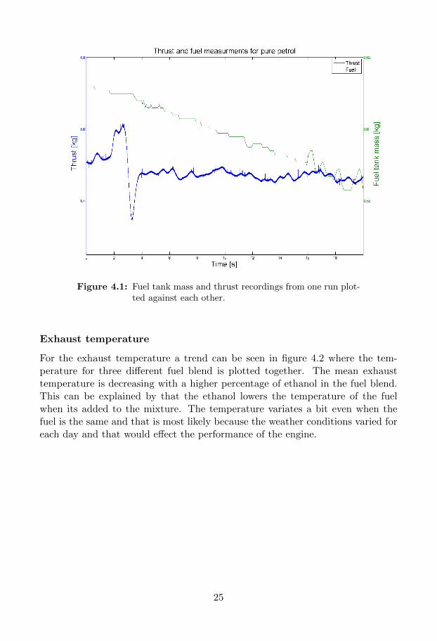
Figure 4.1: Fuel tank mass and thrust recordings from one run plot-ted against each other.
Exhaust temperature
For the exhaust temperature a trend can be seen in figure 4.2 where the tem-perature for three different fuel blend is plotted together. The mean exhausttemperature is decreasing with a higher percentage of ethanol in the fuel blend.This can be explained by that the ethanol lowers the temperature of the fuelwhen its added to the mixture. The temperature variates a bit even when thefuel is the same and that is most likely because the weather conditions varied foreach day and that would effect the performance of the engine.
25
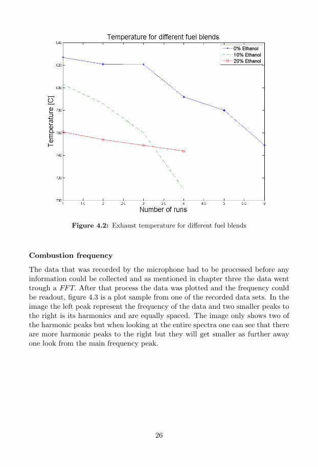
Figure 4.2: Exhaust temperature for different fuel blends
Combustion frequency
The data that was recorded by the microphone had to be processed before anyinformation could be collected and as mentioned in chapter three the data wenttrough a FFT. After that process the data was plotted and the frequency couldbe readout, figure 4.3 is a plot sample from one of the recorded data sets. In theimage the left peak represent the frequency of the data and two smaller peaks tothe right is its harmonics and are equally spaced. The image only shows two ofthe harmonic peaks but when looking at the entire spectra one can see that thereare more harmonic peaks to the right but they will get smaller as further awayone look from the main frequency peak.
26
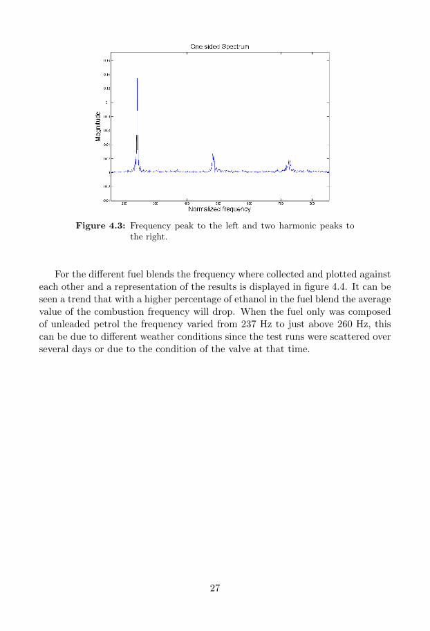
Figure 4.3: Frequency peak to the left and two harmonic peaks tothe right.
For the different fuel blends the frequency where collected and plotted againsteach other and a representation of the results is displayed in figure 4.4. It can beseen a trend that with a higher percentage of ethanol in the fuel blend the averagevalue of the combustion frequency will drop. When the fuel only was composedof unleaded petrol the frequency varied from 237 Hz to just above 260 Hz, thiscan be due to different weather conditions since the test runs were scattered overseveral days or due to the condition of the valve at that time.
27
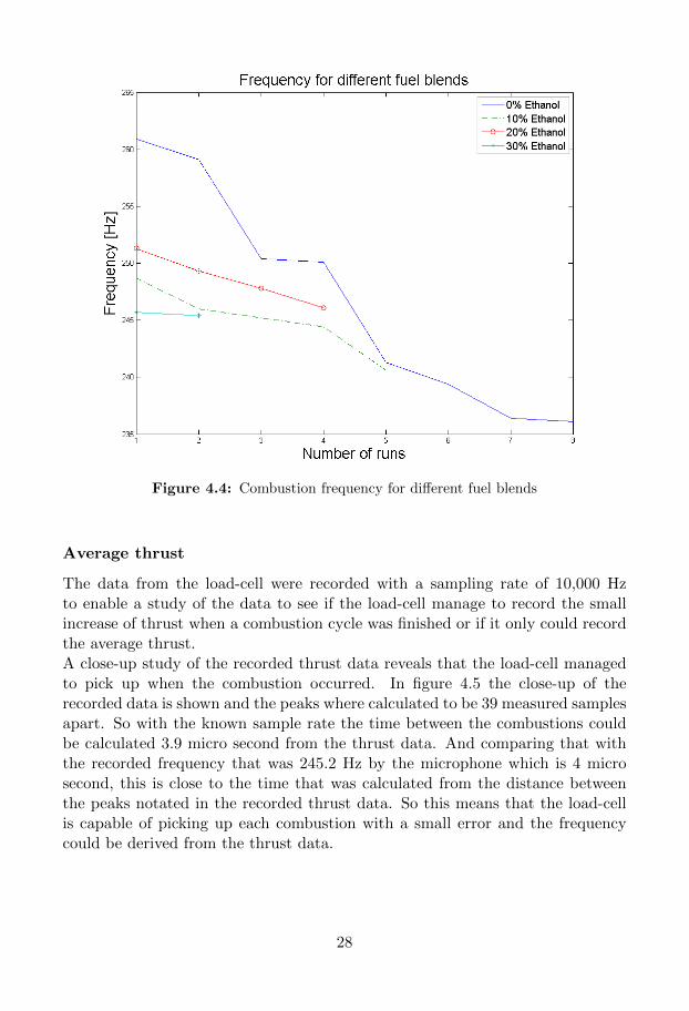
Figure 4.4: Combustion frequency for different fuel blends
Average thrust
The data from the load-cell were recorded with a sampling rate of 10,000 Hzto enable a study of the data to see if the load-cell manage to record the smallincrease of thrust when a combustion cycle was finished or if it only could recordthe average thrust.A close-up study of the recorded thrust data reveals that the load-cell managedto pick up when the combustion occurred. In figure 4.5 the close-up of therecorded data is shown and the peaks where calculated to be 39 measured samplesapart. So with the known sample rate the time between the combustions couldbe calculated 3.9 micro second from the thrust data. And comparing that withthe recorded frequency that was 245.2 Hz by the microphone which is 4 microsecond, this is close to the time that was calculated from the distance betweenthe peaks notated in the recorded thrust data. So this means that the load-cellis capable of picking up each combustion with a small error and the frequencycould be derived from the thrust data.
28
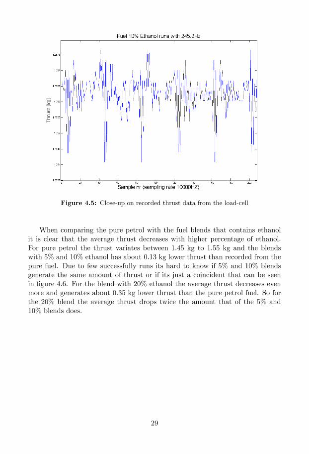
Figure 4.5: Close-up on recorded thrust data from the load-cell
When comparing the pure petrol with the fuel blends that contains ethanolit is clear that the average thrust decreases with higher percentage of ethanol.For pure petrol the thrust variates between 1.45 kg to 1.55 kg and the blendswith 5% and 10% ethanol has about 0.13 kg lower thrust than recorded from thepure fuel. Due to few successfully runs its hard to know if 5% and 10% blendsgenerate the same amount of thrust or if its just a coincident that can be seenin figure 4.6. For the blend with 20% ethanol the average thrust decreases evenmore and generates about 0.35 kg lower thrust than the pure petrol fuel. So forthe 20% blend the average thrust drops twice the amount that of the 5% and10% blends does.
29
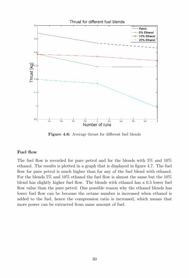
Figure 4.6: Average thrust for different fuel blends
Fuel flow
The fuel flow is recorded for pure petrol and for the blends with 5% and 10%ethanol. The results is plotted in a graph that is displayed in figure 4.7. The fuelflow for pure petrol is much higher than for any of the fuel blend with ethanol.For the blends 5% and 10% ethanol the fuel flow is almost the same but the 10%blend has slightly higher fuel flow. The blends with ethanol has a 0.5 lower fuelflow value than the pure petrol. One possible reason why the ethanol blends haslower fuel flow can be because the octane number is increased when ethanol isadded to the fuel, hence the compression ratio is increased, which means thatmore power can be extracted from same amount of fuel.
30
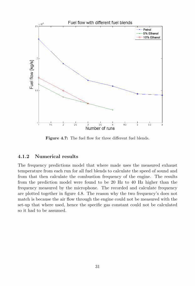
Figure 4.7: The fuel flow for three different fuel blends.
4.1.2 Numerical results
The frequency predictions model that where made uses the measured exhausttemperature from each run for all fuel blends to calculate the speed of sound andfrom that then calculate the combustion frequency of the engine. The resultsfrom the prediction model were found to be 20 Hz to 40 Hz higher than thefrequency measured by the microphone. The recorded and calculate frequencyare plotted together in figure 4.8. The reason why the two frequency’s does notmatch is because the air flow through the engine could not be measured with theset-up that where used, hence the specific gas constant could not be calculatedso it had to be assumed.
31
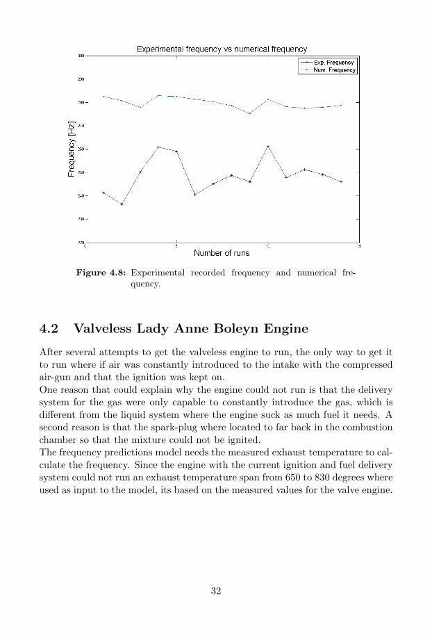
Figure 4.8: Experimental recorded frequency and numerical fre-quency.
4.2 Valveless Lady Anne Boleyn Engine
After several attempts to get the valveless engine to run, the only way to get itto run where if air was constantly introduced to the intake with the compressedair-gun and that the ignition was kept on.One reason that could explain why the engine could not run is that the deliverysystem for the gas were only capable to constantly introduce the gas, which isdifferent from the liquid system where the engine suck as much fuel it needs. Asecond reason is that the spark-plug where located to far back in the combustionchamber so that the mixture could not be ignited.The frequency predictions model needs the measured exhaust temperature to cal-culate the frequency. Since the engine with the current ignition and fuel deliverysystem could not run an exhaust temperature span from 650 to 830 degrees whereused as input to the model, its based on the measured values for the valve engine.
32

Table 4.1: Numerical prediction of combustion frequency for Valve-less Lady Anne Boleyn Engine running on Propane
Exhaust temperature [C] Frequency [Hz]
650 213,98680 215,98710 217,95740 219,89770 221,79800 223,67830 225,50
Table 4.1 shows the results from the predictions model with the chosen tem-perature span, this shows where the combustion frequency is expected to be atfor the designed valveless engine.
33
Chapter 5
Summary and Conclusions
The purpose for this project was to study the effect on the performance for theengine when running on alternative fuels, also to make a working predictionsmodel for the both engine designs. Then using the results to decide if the enginesare suitable to propel UAV’s on the new fuel blends. Simple Helmholtz resonatorand pipe frequency equations have shown to be able to predict the performancefrequency for the valved Redhead pulse-jet engine with only a small error withthe engine running on fuel blend containing ethanol. The error that occurs isdue to not obtaining the right value of the air/fuel ratio that is needed in theperformance predictions to calculate the specific gas constant. This model canafter some adjustments be used to predict the frequency performance for otherdesigns of valved pulse-jet engine. Due to no successfully runs of the valvelessLady Anne Boleyn engine the performance predictions model could not be provenif it works. It was found in this project that although the valved engine is designto run on pure petrol it can run on petrol mixed with up to 10% ethanol withno big changes to the performance. Also it was found that adding ethanol to thepetrol the fuel consumption of the engine will decrease. This is important dueto the rising prices of petrol and adding ethanol will also decrease the harmfulsubstances that is present in the exhaust fumes. Since the engine could runsmoothly on the 10% blend and with just a small decrease in the performance itscapable to propel a UAV. Due to time restrictions, not enough runs where madewith the valved engine to get a wider data collection. Also there where no timeto improve the gas system for the valveless engine that would make it capable torun. Future work to address these shortcomings in the results are discussed inthe next section.
34
Chapter 6
Future Work
To get a complete working model to describe more performance parameters thanjust the combustion frequency of different fuel blends some adjustment and im-provement of the experimental test rig needs to be done.
• Enable pressure and temperature measurements in the combustion chamberand intake of the engine to acquire data that will make it possible to extendthe performance model.
• Redesign the gas delivery system so that the gas only flow into the engineduring the right stage in the combustion cycle rather than a constant flow.
• Run the engine inside with an extraction fan to prevent the weather impacton the engine performance.
• Look into the possibility to change the liquid fuel system so that its possibleto throttle the engine.
35

Appendix A
Drawings
36
1 1
2 2
3 3
4 4
AA
BB
CC
DD
SH
EET 1 O
F 1
DRAW
N
CH
ECKED
QA
MFG
APPRO
VED
Johanna
2014-09-18
DW
G N
O
intake
TITLE
SIZE
C
SCALE
REV
23.00mm
10.00m
m
70.00m
m
44.00m
m
In
ta
ke
Va
lve
le
ss P
ulse
je
t E
ng
in
e
1 1
2 2
3 3
4 4
AA
BB
CC
DD
SH
EET 1 O
F 1
DRAW
N
CH
ECKED
QA
MFG
APPRO
VED
Johanna
2014-09-18
DW
G N
O
cham
ber
TITLE
SIZE
C
SCALE
REV
65.01mm
11.00mm
12.00m
m
30.01mm
171.00m
m
44.00m
m
71.00m
m
26.00mm
30.00mm
Co
mb
ustio
n C
ha
mb
er
Va
lvele
ss P
ulseje
t E
ng
in
e
1 1
2 2
3 3
4 4
AA
BB
CC
DD
SH
EET 1 O
F 1
DRAW
N
CH
ECKED
QA
MFG
APPRO
VED
Johanna
2014-09-18
DW
G N
O
exhaust-1
TITLE
SIZE
C
SCALE
REV
363.00m
m
82.00m
m
38.00m
m
243.00m
m
33.00mm
43.00mm
30.00mm
65.00
Ex
ha
ust p
ip
e
Va
lve
less P
ulse
je
t E
ng
in
e

Appendix B
MATLAB code
%-----------------------------------------------------------------------% Pulsejet engine Preformance Prediction Model%-----------------------------------------------------------------------%-----Valvless----------------------------------------------------------
% Changing constantsT i=288.15; % inlet tempature [K]T e=273.15+830 % exhaust tempature [K]p a=1.0135; % air pressure
% constantsgamma a=1.4; % airgamma g=4*10ˆ(-12)*T eˆ3+4*10ˆ(-9)*T eˆ2-8*10ˆ(-5)*T e+1.3731; % gasR=286.9; % spec. gas constant airR g=189; % spec. gas constant propanS i=0.0003801327; % cross-sec area inlet [mˆ2]S e=0.0032169908; % cross-sec area exhaust [mˆ2]V=0.000319193; % combustion volume [mˆ3]l i=0.124; % inlet length [m]l e=0.363; % exhaust length [m]rho air=1.205; % density [kg/mˆ3]rho prop=1.882; % density [kg/mˆ3]
% local speed of soundc i=sqrt(gamma a*R*T i);c e=sqrt(gamma g*R g*T e);
%-------------------------------------------------------------------------% Frequence, Helmholtz resonator%-------------------------------------------------------------------------% inlet:f i=c i/(2*pi)*sqrt(S i/(V*l i));
% exhaust:
40

f int=[0:2000];f1=tan(2*pi*f int*l e./c e);f2=S e*c e./(2*pi*f int*V);[f e,yout]=intersections(f int,f1,f int,f2,1);
% Totalf tot=(f i+f e(1))/2
%% Valved pulsejet engine%% % Changing constantsvT i=288.15; % inlet tempature [K]vT e=273.15+761; % exhaust tempature [K]%%%% kolla upp r tt vrden!!!!!!p a=1.0135; % air pressure
% constantsgamma a=1.4; % unburntgamma g=4*10ˆ(-12)*vT eˆ3+4*10ˆ(-9)*vT eˆ2-8*10ˆ(-5)*vT e+1.3731; % burntR=287;R g=290.9; % spec. gas constant fuel mixvS i=0.00045344; % cross-sec area inlet [mˆ2]vS e=0.0007917;%0.00114; % cross-sec area exhaust [mˆ2]vV=0.00031004; % combustion volume [mˆ3]vl i=0.0588; % inlet length [m]vl e=0.36274; % exhaust length [m]
% local speed of soundvc i=sqrt(gamma a*R*vT i);vc e=sqrt(gamma g*R g*vT e);
%--------------------------------------------------------------------------% Frequence%-------------------------------------------------------------------% inletvf i=vc i/(2*pi)*sqrt(vS i/(vV*vl i));fprintf('Frequence for the inlet\n',vf i)vf i
% exhaustvf e=vc e/(6*vl e);fprintf('Frequence at the exhaust\n',vf e)vf e
% Totalvf tot=(vf i+vf e(1))/2;fprintf('Total frequence for the engine \n',vf tot)vf tot
41

function [x0,y0,iout,jout] = intersections(x1,y1,x2,y2,robust)%INTERSECTIONS Intersections of curves.% Computes the (x,y) locations where two curves intersect. The curves% can be broken with NaNs or have vertical segments.%% Example:% [X0,Y0] = intersections(X1,Y1,X2,Y2,ROBUST);%% where X1 and Y1 are equal-length vectors of at least two points and% represent curve 1. Similarly, X2 and Y2 represent curve 2.% X0 and Y0 are column vectors containing the points at which the two% curves intersect.%% ROBUST (optional) set to 1 or true means to use a slight variation of the% algorithm that might return duplicates of some intersection points, and% then remove those duplicates. The default is true, but since the% algorithm is slightly slower you can set it to false if you know that% your curves don't intersect at any segment boundaries. Also, the robust% version properly handles parallel and overlapping segments.%% The algorithm can return two additional vectors that indicate which% segment pairs contain intersections and where they are:%% [X0,Y0,I,J] = intersections(X1,Y1,X2,Y2,ROBUST);%% For each element of the vector I, I(k) = (segment number of (X1,Y1)) +% (how far along this segment the intersection is). For example, if I(k) =% 45.25 then the intersection lies a quarter of the way between the line% segment connecting (X1(45),Y1(45)) and (X1(46),Y1(46)). Similarly for% the vector J and the segments in (X2,Y2).%% You can also get intersections of a curve with itself. Simply pass in% only one curve, i.e.,%% [X0,Y0] = intersections(X1,Y1,ROBUST);%% where, as before, ROBUST is optional.
% Version: 1.12, 27 January 2010% Author: Douglas M. Schwarz% Email: dmschwarz=ieee*org, dmschwarz=urgrad*rochester*edu% Real email = regexprep(Email,{'=','*'},{'@','.'})
% Theory of operation:%% Given two line segments, L1 and L2,%% L1 endpoints: (x1(1),y1(1)) and (x1(2),y1(2))% L2 endpoints: (x2(1),y2(1)) and (x2(2),y2(2))%% we can write four equations with four unknowns and then solve them. The
42

% four unknowns are t1, t2, x0 and y0, where (x0,y0) is the intersection of% L1 and L2, t1 is the distance from the starting point of L1 to the% intersection relative to the length of L1 and t2 is the distance from the% starting point of L2 to the intersection relative to the length of L2.%% So, the four equations are%% (x1(2) - x1(1))*t1 = x0 - x1(1)% (x2(2) - x2(1))*t2 = x0 - x2(1)% (y1(2) - y1(1))*t1 = y0 - y1(1)% (y2(2) - y2(1))*t2 = y0 - y2(1)%% Rearranging and writing in matrix form,%% [x1(2)-x1(1) 0 -1 0; [t1; [-x1(1);% 0 x2(2)-x2(1) -1 0; * t2; = -x2(1);% y1(2)-y1(1) 0 0 -1; x0; -y1(1);% 0 y2(2)-y2(1) 0 -1] y0] -y2(1)]%% Let's call that A*T = B. We can solve for T with T = A\B.%% Once we have our solution we just have to look at t1 and t2 to determine% whether L1 and L2 intersect. If 0 <= t1 < 1 and 0 <= t2 < 1 then the two% line segments cross and we can include (x0,y0) in the output.%% In principle, we have to perform this computation on every pair of line% segments in the input data. This can be quite a large number of pairs so% we will reduce it by doing a simple preliminary check to eliminate line% segment pairs that could not possibly cross. The check is to look at the% smallest enclosing rectangles (with sides parallel to the axes) for each% line segment pair and see if they overlap. If they do then we have to% compute t1 and t2 (via the A\B computation) to see if the line segments% cross, but if they don't then the line segments cannot cross. In a% typical application, this technique will eliminate most of the potential% line segment pairs.
% Input checks.error(nargchk(2,5,nargin))
% Adjustments when fewer than five arguments are supplied.switch nargin
case 2robust = true;x2 = x1;y2 = y1;self intersect = true;
case 3robust = x2;x2 = x1;y2 = y1;self intersect = true;
43

case 4robust = true;self intersect = false;
case 5self intersect = false;
end
% x1 and y1 must be vectors with same number of points (at least 2).if sum(size(x1) > 1) ~= 1 | | sum(size(y1) > 1) ~= 1 | | ...
length(x1) ~= length(y1)error('X1 and Y1 must be equal-length vectors of at least 2 points.')
end% x2 and y2 must be vectors with same number of points (at least 2).if sum(size(x2) > 1) ~= 1 | | sum(size(y2) > 1) ~= 1 | | ...
length(x2) ~= length(y2)error('X2 and Y2 must be equal-length vectors of at least 2 points.')
end
% Force all inputs to be column vectors.x1 = x1(:);y1 = y1(:);x2 = x2(:);y2 = y2(:);
% Compute number of line segments in each curve and some differences we'll% need later.n1 = length(x1) - 1;n2 = length(x2) - 1;xy1 = [x1 y1];xy2 = [x2 y2];dxy1 = diff(xy1);dxy2 = diff(xy2);
% Determine the combinations of i and j where the rectangle enclosing the% i'th line segment of curve 1 overlaps with the rectangle enclosing the% j'th line segment of curve 2.[i,j] = find(repmat(min(x1(1:end-1),x1(2:end)),1,n2) <= ...
repmat(max(x2(1:end-1),x2(2:end)).',n1,1) & ...repmat(max(x1(1:end-1),x1(2:end)),1,n2) >= ...repmat(min(x2(1:end-1),x2(2:end)).',n1,1) & ...repmat(min(y1(1:end-1),y1(2:end)),1,n2) <= ...repmat(max(y2(1:end-1),y2(2:end)).',n1,1) & ...repmat(max(y1(1:end-1),y1(2:end)),1,n2) >= ...repmat(min(y2(1:end-1),y2(2:end)).',n1,1));
% Force i and j to be column vectors, even when their length is zero, i.e.,% we want them to be 0-by-1 instead of 0-by-0.i = reshape(i,[],1);j = reshape(j,[],1);
% Find segments pairs which have at least one vertex = NaN and remove them.
44

% This line is a fast way of finding such segment pairs. We take% advantage of the fact that NaNs propagate through calculations, in% particular subtraction (in the calculation of dxy1 and dxy2, which we% need anyway) and addition.% At the same time we can remove redundant combinations of i and j in the% case of finding intersections of a line with itself.if self intersect
remove = isnan(sum(dxy1(i,:) + dxy2(j,:),2)) | j <= i + 1;else
remove = isnan(sum(dxy1(i,:) + dxy2(j,:),2));endi(remove) = [];j(remove) = [];
% Initialize matrices. We'll put the T's and B's in matrices and use them% one column at a time. AA is a 3-D extension of A where we'll use one% plane at a time.n = length(i);T = zeros(4,n);AA = zeros(4,4,n);AA([1 2],3,:) = -1;AA([3 4],4,:) = -1;AA([1 3],1,:) = dxy1(i,:).';AA([2 4],2,:) = dxy2(j,:).';B = -[x1(i) x2(j) y1(i) y2(j)].';
if robustoverlap = false(n,1);warning state = warning('off','MATLAB:singularMatrix');% Use try-catch to guarantee original warning state is restored.try
lastwarn('')for k = 1:n
T(:,k) = AA(:,:,k)\B(:,k);[unused,last warn] = lastwarn;lastwarn('')if strcmp(last warn,'MATLAB:singularMatrix')
% Force in range(k) to be false.T(1,k) = NaN;% Determine if these segments overlap or are just parallel.overlap(k) = rcond([dxy1(i(k),:);xy2(j(k),:) - xy1(i(k),:)]) < eps;
endendwarning(warning state)
catch errwarning(warning state)rethrow(err)
end% Find where t1 and t2 are between 0 and 1 and return the corresponding% x0 and y0 values.
45

in range = (T(1,:) >= 0 & T(2,:) >= 0 & T(1,:) <= 1 & T(2,:) <= 1).';% For overlapping segment pairs the algorithm will return an% intersection point that is at the center of the overlapping region.if any(overlap)
ia = i(overlap);ja = j(overlap);% set x0 and y0 to middle of overlapping region.T(3,overlap) = (max(min(x1(ia),x1(ia+1)),min(x2(ja),x2(ja+1))) + ...
min(max(x1(ia),x1(ia+1)),max(x2(ja),x2(ja+1)))).'/2;T(4,overlap) = (max(min(y1(ia),y1(ia+1)),min(y2(ja),y2(ja+1))) + ...
min(max(y1(ia),y1(ia+1)),max(y2(ja),y2(ja+1)))).'/2;selected = in range | overlap;
elseselected = in range;
endxy0 = T(3:4,selected).';
% Remove duplicate intersection points.[xy0,index] = unique(xy0,'rows');x0 = xy0(:,1);y0 = xy0(:,2);
% Compute how far along each line segment the intersections are.if nargout > 2
sel index = find(selected);sel = sel index(index);iout = i(sel) + T(1,sel).';jout = j(sel) + T(2,sel).';
endelse % non-robust option
for k = 1:n[L,U] = lu(AA(:,:,k));T(:,k) = U\(L\B(:,k));
end
% Find where t1 and t2 are between 0 and 1 and return the corresponding% x0 and y0 values.in range = (T(1,:) >= 0 & T(2,:) >= 0 & T(1,:) < 1 & T(2,:) < 1).';x0 = T(3,in range).';y0 = T(4,in range).';
% Compute how far along each line segment the intersections are.if nargout > 2
iout = i(in range) + T(1,in range).';jout = j(in range) + T(2,in range).';
endend
% FFT code to get the frequency%------------------------------------
46

x=[...]; % Recorded frequency datathrust=[...]; % REcorded thrust data
L=length(x);dt=1.0*10ˆ-4;fs=1/dt;t=(0:1:L-1)*dt;out=fft(x,L)/L;plot(fs/2*linspace(0,1,(length(out)/2)+1),abs(out(1:(length(out)/2)+1)))title('One sided Spectrum')xlabel('Normalized frequency')ylabel('Magnitude')avthrust=mean(thrust);newton=avthrust*9.80665
47

Appendix C
Result tables
48

Bibliography
[1] Jesus Diaz. Boeing’s Millennium Falcon Floats Using Nazi Technology.Wired.com, 2011.
[2] Robert Lewis Ordon. Experimental Investigation into The Operational Pa-rameters of a 50 Centimeter Class Pulsejet Engine. PhD thesis, North Car-olina State University, 2006. Chapter 1.
[3] Fei Zheng. Computational Investigation of High Speed Pulsejets. Page 36-38,North Carolina State University, 2009.
[4] J. Coombes, M. Hollands, S. Jones, T. Matte hewson, and R. Smith. De-sign and build a pulsejet engine and thrust measurement stand. Chapter 3,Adelaide University, AUS, 2007.
[5] Bruno Ogorelec. Valveless Pulsejet Engine 1.5 - a historical review of valve-less pulsejet designs, 2005.
[6] Bruce Simpson. The Enthusiast’s Guide to Pulsejet Engines.http://aardvark.co.nz/contact/, 2004. Page 57.
[7] Maja Nylen. Performance Prediction of a Microjet Engine Run on Alterna-tive. Chapter 2.4, Lulea University of Technology, 2013.
[8] C.E. Tharratt. The Propulsive Duct, 1966.
[9] Superior Propane. MSDS Propane.
[10] Ncp alcohols. MSDS Ethanol 100%.
[11] Shell. MSDS Unleaded 91 Petrol.
[12] Douglas Schwarz. Fast and Robust Curve Intersections. MATLAB Central,2010.
50
Related Documents


