47 Dimensions and connection details Product panorama 3 Performance and functionality 11 Masterpact NW08 to NW32 Fixed 3/4-pole device 48 Drawout 3/4-pole device 50 Masterpact NW40 Fixed 3/4-pole device 52 Drawout 3/4-pole device 54 Masterpact NW40b to NW63 Fixed 3/4-pole device 56 Drawout 3/4-pole device 58 NW accessories 60 NW rear panel cutouts 61 NW external modules 62 Electrical diagrams 67 Installation recommendations 75 Protection characteristics 89 Masterpact NW

Welcome message from author
This document is posted to help you gain knowledge. Please leave a comment to let me know what you think about it! Share it to your friends and learn new things together.
Transcript

47
Dimensions and connection details
Product panorama 3Performance and functionality 11
Masterpact NW08 to NW32Fixed 3/4-pole device 48Drawout 3/4-pole device 50
Masterpact NW40Fixed 3/4-pole device 52Drawout 3/4-pole device 54
Masterpact NW40b to NW63Fixed 3/4-pole device 56Drawout 3/4-pole device 58
NW accessories 60
NW rear panel cutouts 61
NW external modules 62
Electrical diagrams 67Installation recommendations 75Protection characteristics 89
Masterpact NW
48
A (*) BB
X
Y
189 (3P)304 (4P)
308
154
20011
11
150191
161
189
11
200 (3P)315 (4P)
Dimensionsand connection details
NW08 to NW32 circuit breakersFixed 3/4-pole device
Dimensions
Mounting on base plate or rails Mounting detail
Safety clearances Door cutout
F : Datum.
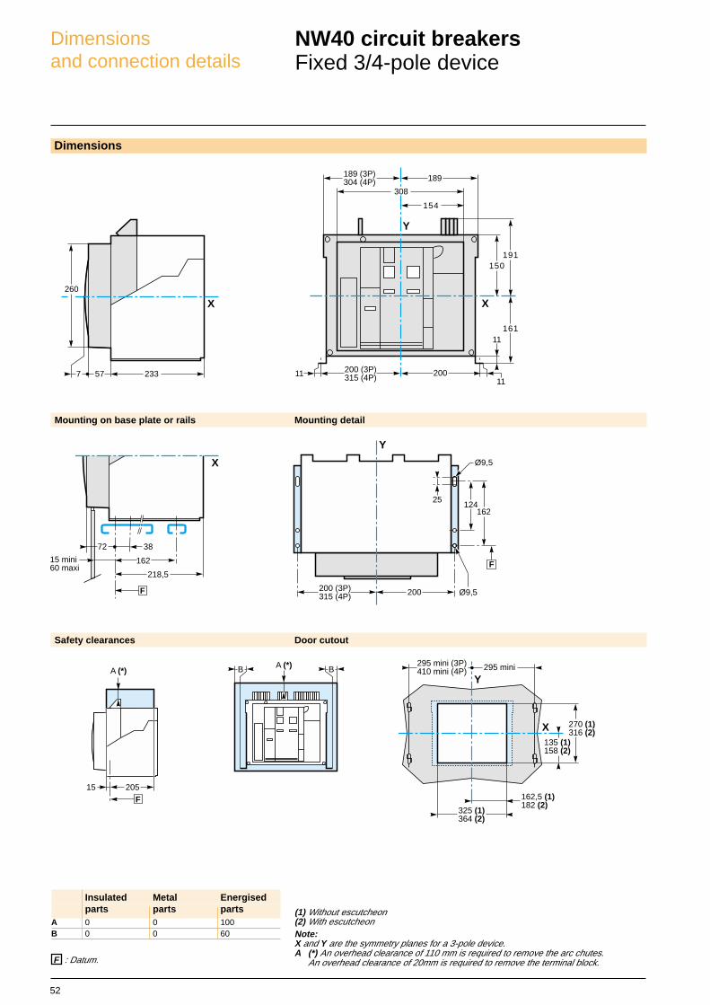
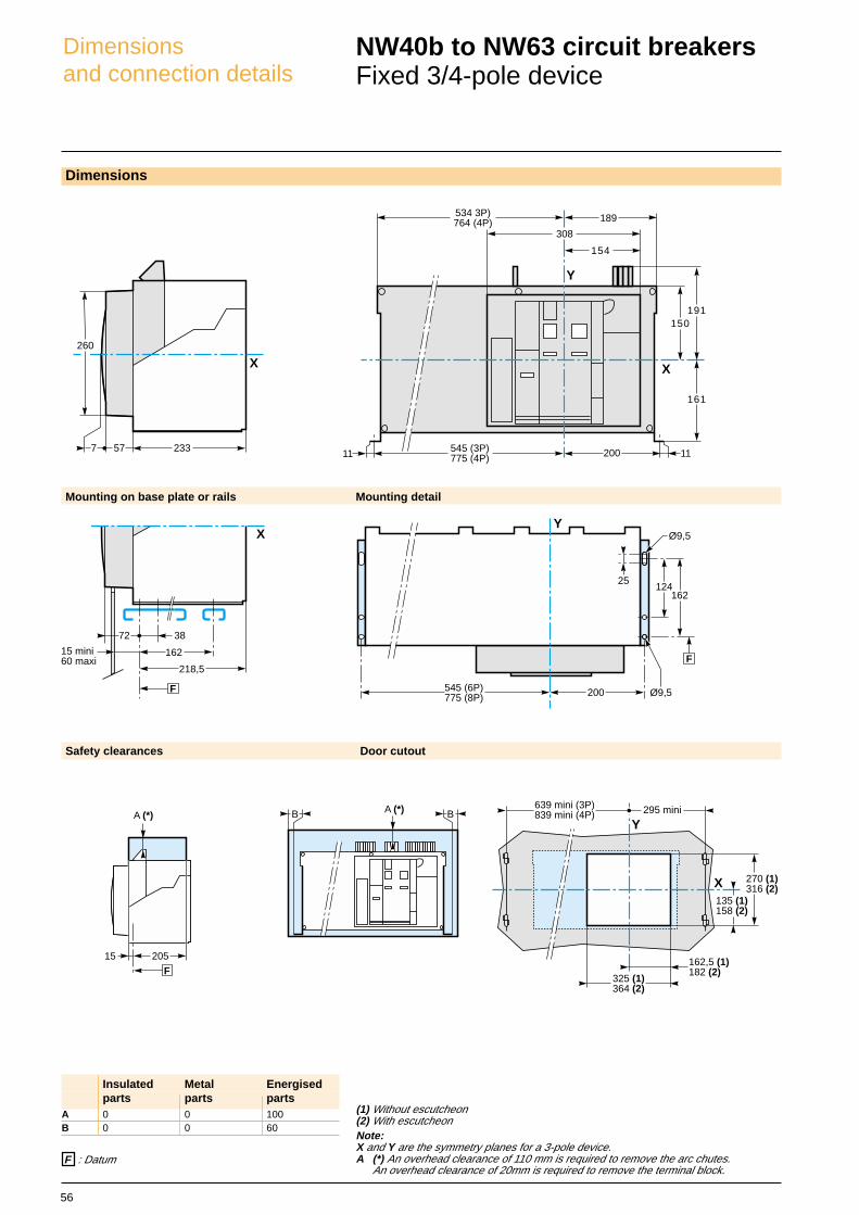
(1) Without escutcheon(2) With escutcheonNote:X and Y are the symmetry planes for a 3-pole device.A (*) An overhead clearance of 110 mm is required to remove the arc chutes.
An overhead clearance of 20mm is required to remove the terminal block.
Insulated Metal Energisedparts parts parts
A 0 0 100B 0 0 60
Y
200
124162
F
Ø9,5
Ø9,5
25
200 (3P)315 (4P)
233577
260
X
162
72 38
15 mini60 maxi
218,5
X
F
Y
X135 (1)158 (2)
270 (1)316 (2)
295 mini (3P)410 mini (4P) 295 mini
162,5 (1)182 (2)
325 (1)364 (2)
20515
A (*)
F
49
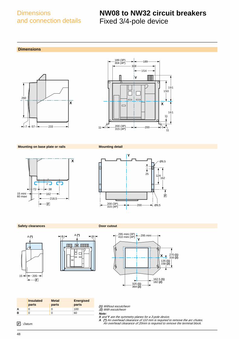
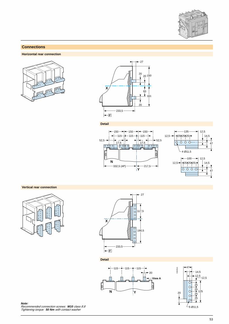
Note:Recommended connection screws: M10 class 8.8Tightening torque: 50 Nm with contact washer
Connections
Horizontal rear connection Détail
Vertical rear connection Detail
Front connection Detail
Y
115115115
N
==
76
13
25
3 Ø11,5
12,5
38
47
14,5
76
253 Ø11,5
38
12,513
47
14,5
=
=
12,5
1325 25
3 Ø11,5
12,5
25 25 13
3 Ø11,5
76
X
230,5
20
219
F
12,5
219,5
12,5
475
View A detail
View A detail
Top connection Bottom connection
masterpact II
MERLIN GERIN
NX 08 HA10
Ui 1000V Uimp 12kV
Ue690
(V)
50kA/1s
IEC 947-2
50/60Hz
EN 60947-2
UTE VDE BS CEI UNE AS NBMA
27
233,5
20
20
20
93
F
150
161
X
X
68
27
141
233,5
F
115115115
YN
View A
20
Y
115115115
N
View A

50
X
Y
220,5 (3P)335,5 (4P)
308
154
200
238,5
200,5
220,5
400
A BB
Dimensionsand connection details
NW08 to NW32 circuit breakersDrawout 3/4-pole device
Ø11,5
Ø10,5
2 Ø11,5 x 22
175
F
162,5167,5 (3P)282,5 (4P)
Y
212,5212,5 (3P)327,5 (4P)
11010
4 Ø6,5
Dimensions
Mounting on base plate or rails Mounting detail
Safety clearances Door cutout
(1) Without escutcheon(2) With escutcheonNote:X and Y are the symmetry planes for a 3-pole device.A (*) An overhead clearance of 110 mm is required to remove the arc chutes.
400mini
60 mini
128 11 383,5
56(*)
X
F
X
103 175
283
110
X
300 mini (3P)415 mini (4P)
Y
300 mini
135 (1)222 (2)
270 (1)379 (2)
153,3 (1)
47 (1)162,5 (1)182 (2)325 (1)
364 (2)
(*) Disconnected position
F : Datum.
Insulated Metal Energisedparts parts parts
A 0 0 0B 0 0 60
F
100225
A
51
masterpact II
MERLIN GERIN
NX 08 HA10
Ui 1000V Uimp 12kV
Ue690
(V)
50kA/1s
IEC 947-2
50/60Hz
EN 60947-2
UTE VDE BS CEI UNE AS NBMA
==
76
13
25
3 Ø11,5
12,5
38
47
14,5
F
X
298,5
20
20
93
20
184
27
296
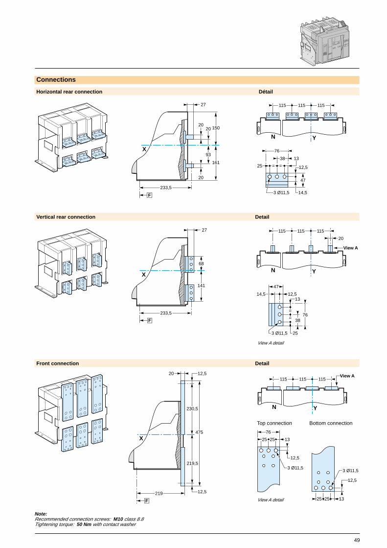
Note:Recommended connection screws: M10 class 8.8Tightening torque: 50 Nm with contact washer
Connections
Horizontal rear connection Detail
Vertical rear connection Detail
Front connection Detail
Y
115115115
N
76
253 Ø11,5
38
12,513
47
14,5
=
=
View A detail
X
27
F
298,5
68
141
1325 25
3 Ø11,5
12,5
25 25 13
3 Ø11,5
76
12,5
View A detail
Top connection Bottom connection
20
X
F
284
151
224
400
12,5
12,5
Y
115115115
N
20
View A
Y
115115115
N
View A
52
A (*) BB
X
Y
189 (3P)304 (4P)
308
154
20011
11
150191
161
189
11
200 (3P)315 (4P)
Dimensionsand connection details
NW40 circuit breakersFixed 3/4-pole device
Dimensions
(1) Without escutcheon(2) With escutcheonNote:X and Y are the symmetry planes for a 3-pole device.A (*) An overhead clearance of 110 mm is required to remove the arc chutes.
An overhead clearance of 20mm is required to remove the terminal block.
Mounting on base plate or rails Mounting detail
Safety clearances Door cutout
Y
200
124162
F
Ø9,5
Ø9,5
25
200 (3P)315 (4P)
233577
260
X
162
72 38
15 mini60 maxi
218,5
X
F
Y
X135 (1)158 (2)
270 (1)316 (2)
295 mini (3P)410 mini (4P) 295 mini
162,5 (1)182 (2)
325 (1)364 (2)
F : Datum.
Insulated Metal Energisedparts parts parts
A 0 0 100B 0 0 60
20515
A (*)
F
53
Note:Recommended connection screws: M10 class 8.8Tightening torque: 50 Nm with contact washer
Connections
Horizontal rear connection
Vertical rear connection
Detail
Detail
Y
115115115
N
52,517,5
52,5
217,5332,5 (4P)
150 150 150
17,5
E46
491A
125
25
12,5
47
25
25
25
14,5
12,5
5 Ø11,5
20
4 Ø11,5
14,525252512,5
47
135 12,5
14,525252512,5
47
100 12,5
masterpact II
MERLIN GERIN
NX 08 HA10
Ui 1000V Uimp 12kV
Ue690
(V)
50kA/1s
IEC 947-2
50/60Hz
EN 60947-2
UTE VDE BS CEI UNE AS NBMA
27
233,5
20
20
20
93
F
150
161
X
117,5
27
190,5
233,5
F
X
115115115
YN
View A
20
54
X
Y
220,5 (3P)335,5 (4P)
308
154
200
238,5
200,5
220,5
400
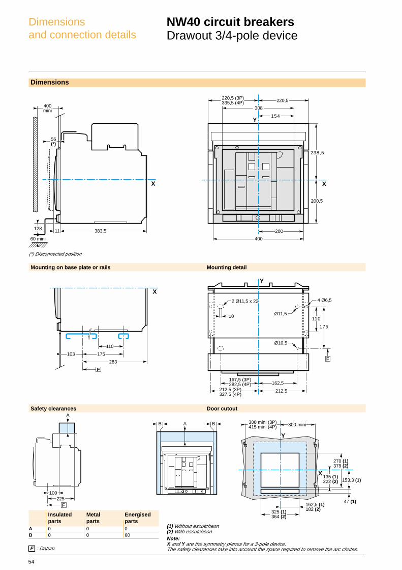
Dimensionsand connection details
NW40 circuit breakersDrawout 3/4-pole device
X
300 mini (3P)415 mini (4P)
Y
300 mini
135 (1)222 (2)
270 (1)379 (2)
153,3 (1)
47 (1)162,5 (1)182 (2)325 (1)
364 (2)
Dimensions
(1) Without escutcheon(2) With escutcheonNote:X and Y are the symmetry planes for a 3-pole device.The safety clearances take into account the space required to remove the arc chutes.
Mounting on base plate or rails Mounting detail
Safety clearances Door cutout
A BB
(*) Disconnected position
400mini
60 mini
128 11 383,5
56(*)
X
F
X
103 175
283
110
Ø11,5
Ø10,5
2 Ø11,5 x 22
175
F
162,5167,5 (3P)282,5 (4P)
Y
212,5212,5 (3P)327,5 (4P)
11010
4 Ø6,5
F : Datum.
Insulated Metal Energisedparts parts parts
A 0 0 0B 0 0 60
F
100225
A

55
Note:Recommended connection screws: M10 class 8.8Tightening torque: 50 Nm with contact washer
Connections
Horizontal rear connection
Y
115115115
N
52,517,5
52,5
332,5 217,5
150150150
17,5
F
X
298,5
20
20
93
20
184
27
296E
4636
4A
125
25
12,5
47
25
25
25
14,5
12,5
5 Ø11,5
20
Vertical rear connection
Detail
Detail
X
117,5
190,5
F
298,5
27
4 Ø11,5
14,525252512,5
47
135 12,5
14,525252512,5
47
100 12,5
View A detail
masterpact II
MERLIN GERIN
NX 08 HA10
Ui 1000V Uimp 12kV
Ue690
(V)
50kA/1s
IEC 947-2
50/60Hz
EN 60947-2
UTE VDE BS CEI UNE AS NBMA
Y
115115115
N
20
View A
56
BB A (*)
X
Y
534 3P)764 (4P)
308
154
200 1111
150191
161
189
545 (3P)775 (4P)
Dimensionsand connection details
NW40b to NW63 circuit breakersFixed 3/4-pole device
Dimensions
Mounting on base plate or rails Mounting detail
Safety clearances Door cutout
233577
260
X
Y
200
124162
F
Ø9,5
Ø9,5
25
545 (6P)775 (8P)
162
72 38
15 mini60 maxi
218,5
X
F
Y
X
639 mini (3P)839 mini (4P) 295 mini
135 (1)158 (2)
270 (1)316 (2)
162,5 (1)182 (2)
325 (1)364 (2)
(1) Without escutcheon(2) With escutcheonNote:X and Y are the symmetry planes for a 3-pole device.A (*) An overhead clearance of 110 mm is required to remove the arc chutes.
An overhead clearance of 20mm is required to remove the terminal block. F : Datum
Insulated Metal Energisedparts parts parts
A 0 0 100B 0 0 60
20515
A (*)
F
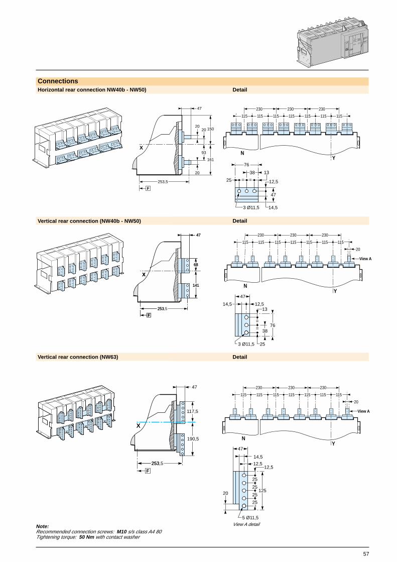
57
Vertical rear connection (NW40b - NW50)
Note:Recommended connection screws: M10 s/s class A4 80Tightening torque: 50 Nm with contact washer
ConnectionsHorizontal rear connection NW40b - NW50) Detail
Vertical rear connection (NW63)
Detail
Detail
View A detail
masterpact II
MERLIN GERIN
NX 63 HA
Ui 1000V Uimp 12kV
Ue690
(V)
Icw 85kA/1s
IEC 947-2
50/60Hz
EN 60947-2
UTE VDE BS CEI UNE AS NBMA
47
253,5
20
20
20
93
F
150
161
X
Y
115115115
N
115115115115
230 230 230
==
76
13
25
3 Ø11,5
12,5
38
47
14,5
115115115
YN
View A
115115115115
230230230
20
76
253 Ø11,5
38
12,513
47
14,5
=
=
XX
68
47
141
253
F
68
47
141
253,5
F
115115115
YN
View A
115115115115
230230230
20
X
47
190,5
253
117,5
253,5
F
125
25
12,5
47
25
25
25
14,5
12,5
5 Ø11,5
20
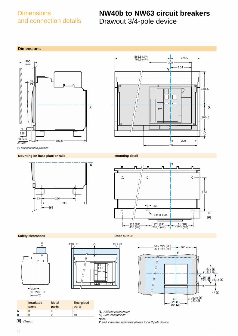
58
A BB
X
Y
565,5 (3P)795,5 (4P)
308
154
200
238,5
200,5
220,5
400
40
Dimensionsand connection details
NW40b to NW63 circuit breakersDrawout 3/4-pole device
Dimensions
Mounting on base plate or rails Mounting detail
Safety clearances Door cutout
(*) Disconnected position
400mini
60 mini
128
11 383,5
56(*)
X
F
X
53 250
333
250
F
151 (3P)162,5 (4P)
174 (3P)287,5 (4P)
325 (3P)450 (4P)
Y
6 Ø11 x 34
23
X
646 mini (3P)876 mini (4P)
Y
300 mini
135 (1)222 (2)
270 (1)379 (2)
153,3 (1)
47 (1)
162,5 (1)182 (2)325 (1)
364 (2)
(1) Without escutcheon(2) With escutcheonNote:X and Y are the symmetry planes for a 3-pole device. F : Datum.
Insulated Metal Energisedparts parts parts
A 0 0 0B 0 0 60
F
100225
A
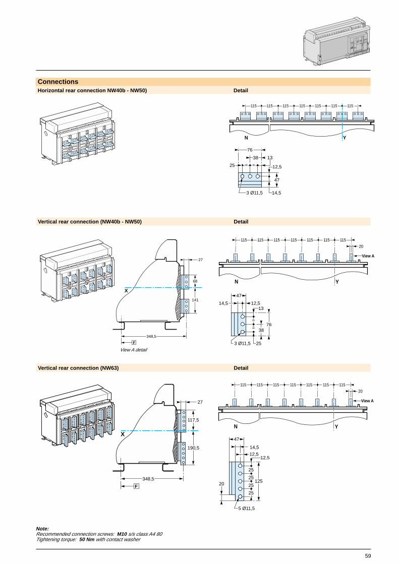
59
Note:Recommended connection screws: M10 s/s class A4 80Tightening torque: 50 Nm with contact washer
ConnectionsHorizontal rear connection NW40b - NW50) Detail
Vertical rear connection (NW63) Detail
Vertical rear connection (NW40b - NW50) Detail
masterpact II
MERLIN GERIN
NX 08 HA10
Ui 1000V Uimp 12kV
Ue690
(V)
50kA/1s
IEC 947-2
50/60Hz
EN 60947-2
UTE VDE BS CEI UNE AS NBMA
View A detail
==
76
13
25
3 Ø11,5
12,5
38
47
14,5
Y
115115115
N
115115115115
68
141
F
X
348,5
27
20
View A
Y
115115115
N
115115115115
76
253 Ø11,5
38
12,513
47
14,5
=
=
190,5
F
X
348,5
27
117,5
20
View A
Y
115115115
N
115115115115
125
25
12,5
47
25
25
25
14,5
12,5
5 Ø11,5
20

60
X
Y
11
113159
429 (3P)544 (4P)
11407 (3P)522 (4P)
96125
4 Ø12
203,5
Dimensionsand connection details
NW accessories
X
253,5
F
172
183
20
2067
Y
115115115
N
67
X
253,5
F
220
231
76
253 Ø11,5
38
12,513
47
14,5
=
=
Disconnectable front-connection adapter (Masterpact NW08 to NW32)
Horizontal rear connection Detail
Vertical rear connection Detail
Note:Recommended connection screws: M10 class 8.8Tightening torque: 50 Nm with contact washer View A detail
==
76
13
25
3 Ø11,5
12,5
38
47
14,5
E46
057A
Mounting on backplate with special brackets (Masterpact NW08 to NW32 fixed front-connected).
X
218,5 4,5
F
F Datum
View A
Y
115115115
N
20
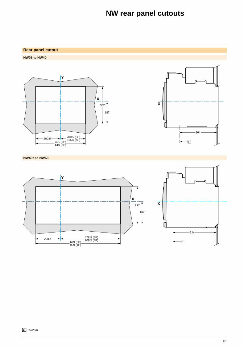
61
X
264
F
X
Y
200,5
302
187
401 (3P)516 (4P)
200,5 (3P)315,5 (4P)
X
314
F
X
Y
297
200,5
182
679 (3P)909 (4P)
478,5 (3P)708,5 (4P)
NW40b to NW63
NW rear panel cutouts
Rear panel cutout
NW08 to NW40
F : Datum

62
Dimensionsand connection details
NW external modules
M6C relay module
External power supply module (AD)
Battery module (BAT)Mounting
1 3 5 7 9 11 13 15 17 19 21 23
M6c
25
1 3 5 7 9 1117 19 21 23 25
2 4 6 8 10 12 14 16 18 20 22 24S1S2
24V 0V com.
S3S4
S5S6
S1S2S3S4S5S6
81
42
9966
1 3 5 7 9 11 13 15 17 19 21 23
M6c
25
1 3 5 7 9 1117 19 21 23 25
2 4 6 8 10 12 14 16 18 20 22 24S1S2
24V 0V com.
S3S4
S5S6
S1S2S3S4S5S6
3 5 7 9 11 13 15 17 19 21 23
M6c
25
1 3 5 7 9 1117 19 21 23 25
2 4 6 8 10 12 14 16 18 20 22 24S1S2
24V 0V com.
S3S4
S5S6
S1S2S3S4S5S6
99
46
L3
G1
AD 220A
L4
G2
Input
24VDC
+Output
24VDC
73
75112
60
60 2 Ø6
L3
G1
AD 220A
L4
G2
Input
24VDC
+Output
24VDC
H3
H2
BAT 24V
H4
H1
Input
24VDC
+Output
24VDC
+ 73
75112
60
60 2 Ø6
H3
H2
BAT 24V
H4
H1
Input
24VDC
+Output
24VDC
+
Connection of auxiliary wiring to terminal block
One conductor only per connection point
S : 2,5 mm2
S : 0,6 mm2
8
2
1
Ø3,5

63
57
66
2 Ø4,2
3 6
MNUVR
1012
100/130 V
AC/DC
S
0.5 1
3 1.5
Retardateur de MN
Time delay for UVR
4 5 6
1 2 3
1 2 3
3 6
MNUVR
1012
100/130 V
AC/DC
S
0.5 1
3 1.5
Retardateur de MN
Time delay for UVR
4 5 63
3
73
46
Delay unit for MN releaseMNR
3 6
MNUVR
1012
100/130 V
AC/DC
S
0.5 1
3 1.5
Retardateur de MN
Time delay for UVR
4 5 6
1 2 3
1 2 3
7273,5
81 42
“Chassis” communication moduleModBUS BatiBUS
External sensor for source ground return (SGR) protectionSensor “MGDF summer” module
+
+
CCM modbus
Rés
eau
Net
wor
k
Fault
Com.
Address
sync.
shie
ldB
’ A’ B A
B’ A’ B A
Dis
jonc
teur
Bre
aker
+
CE
CD
CT
45
5458
90
MDGF
45
200
150
76
130
Dimensionsand connection details
64
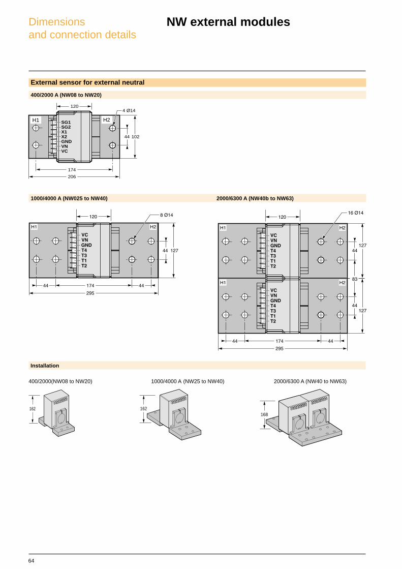
Dimensionsand connection details
NW external modules
External sensor for external neutral
400/2000 A (NW08 to NW20)
1000/4000 A (NW025 to NW40) 2000/6300 A (NW40b to NW63)
SG1SG2X1X2GNDVNVC
4 Ø14
44
206
102
174
120
Installation
400/2000(NW08 to NW20) 1000/4000 A (NW25 to NW40) 2000/6300 A (NW40 to NW63)
162 162168
H1 H2
65
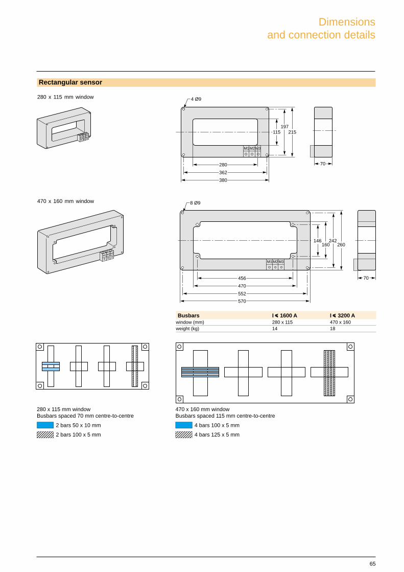
Busbars I iiiii 1600 A I iiiii 3200 Awindow (mm) 280 x 115 470 x 160weight (kg) 14 18
280 x 115 mm windowBusbars spaced 70 mm centre-to-centre
2 bars 50 x 10 mm
2 bars 100 x 5 mm12345678123456781234567812345678
470 x 160 mm windowBusbars spaced 115 mm centre-to-centre
4 bars 100 x 5 mm
4 bars 125 x 5 mm123456789123456789123456789123456789
M1 M2 M3
70280
M1 M2 M3
197115 215
362
380
4 Ø9280 x 115 mm window
470 x 160 mm window
M1 M2 M3
70
M1 M2 M3
456
470
552
570
146160
242260
8 Ø9
Rectangular sensor
Dimensionsand connection details

66

67
Electrical diagrams
Product panorama 3Performance and functionality 11Dimensions and connection details 45
NW08 to NW63 68
COMs option and earth fault 70
Earth fault and earth leakage 72
Installation recommendations 75Protection characteristics 91
Masterpact NW
68
T4
T3
T2
T1
Micrologic
Z4
Z3
Z2
Z1
Z2
Z1N L3L2L1
Q
Z5
VN
V1
V2
V3
M3
M2
M1
F2+
F1
I
U
24 V DCX2
X1
SG
2
SG
1
Z3
Z4
Z5
Z2
Z1
Z3
Z4
Z5
power upstream cb downstream cb
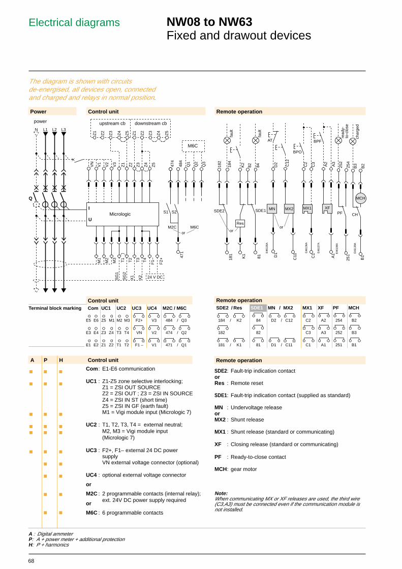
Electrical diagrams NW08 to NW63Fixed and drawout devices
The diagram is shown with circuitsde-energised, all devices open, connectedand charged and relays in normal position.
E46
139A
471
S1
474
484
S2
Q1
Q2
Q3
M6C
M2C M6Cor
MX1
C2
C3
C1
BPO
A2
A3
A1
BPF
XFPF
252
254
251
read
y-to
-clo
se
B1
MCH
B3
B2
CH
char
ged
E46
135A
E46
136A
E46
137A
E46
138A
181
182
184
SDE2
81
82 84
SDE1
K2
Res
K1
faul
t
faul
t
or
D2
D1
AT
MN MX2
C12
C11
or
A P H
c c c
c c c
c c c
c c cc c c
c c c
c c
c c
c c
c c
/
/
Power
Com: E1-E6 communication
UC1 : Z1-Z5 zone selective interlocking;Z1 = ZSI OUT SOURCEZ2 = ZSI OUT ; Z3 = ZSI IN SOURCEZ4 = ZSI IN ST (short time)Z5 = ZSI IN GF (earth fault)M1 = Vigi module input (Micrologic 7)
UC2 : T1, T2, T3, T4 = external neutral;M2, M3 = Vigi module input(Micrologic 7)
UC3 : F2+, F1– external 24 DC powersupplyVN external voltage connector (optional)
UC4 : optional external voltage connector
or
M2C : 2 programmable contacts (internal relay);ext. 24V DC power supply required
or
M6C : 6 programmable contacts
Control unit
Control unit
SDE2: Fault-trip indication contactorRes : Remote reset
SDE1: Fault-trip indication contact (supplied as standard)
MN : Undervoltage releaseorMX2 : Shunt release
MX1 : Shunt release (standard or communicating)
XF : Closing release (standard or communicating)
PF : Ready-to-close contact
MCH: gear motor
Note:When communicating MX or XF releases are used, the third wire(C3,A3) must be connected even if the communication module isnot installed.
A : Digital ammeterP: A + power meter + additional protectionH: P + harmonics
/
/
Remote operation
Control unitCom UC1 UC2 UC3 UC4 M2C / M6C
E5 E6 Z5 M1 M2 M3 F2+ V3 484 Q3
E3 E4 Z3 Z4 T3 T4 VN V2 474 Q2
E1 E2 Z1 Z2 T1 T2 F1 – V1 471 Q1
/
/
/
Remote operation
Terminal block marking
Remote operationSDE2 / Res SDE1 MN / MX2 MX1 XF PF MCH
184 K2 84 D2 C12 C2 A2 254 B2
182 82 C3 A3 252 B3
181 K1 81 D1 C11 C1 A1 251 B1
69
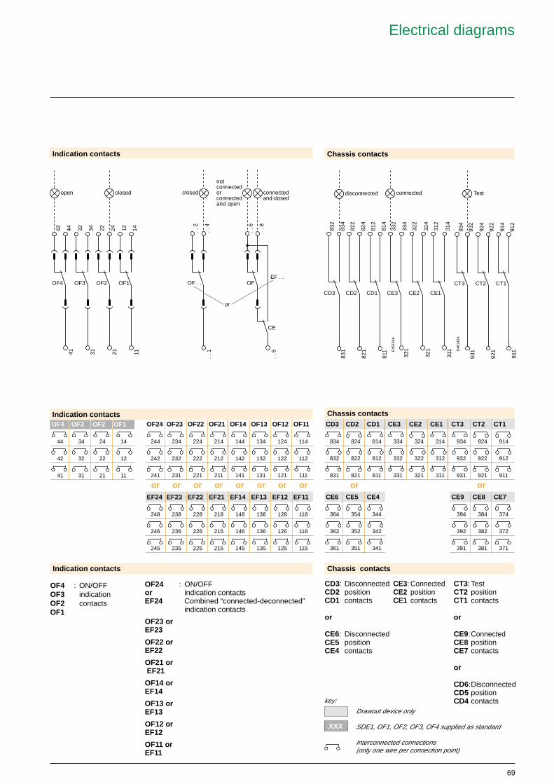
key:
Drawout device only
SDE1, OF1, OF2, OF3, OF4 supplied as standard
Interconnected connections(only one wire per connection point)
OF24 : ON/OFFor indication contactsEF24 Combined “connected-deconnected”
indication contacts
OF23 orEF23
OF22 orEF22
OF21 or EF21
OF14 orEF14
OF13 orEF13
OF12 orEF12
OF11 orEF11
OF4 : ON/OFFOF3 indicationOF2 contactsOF1
EF24 EF23 EF22 EF21 EF14 EF13 EF12 EF11
248 238 228 218 148 138 128 118
246 236 226 216 146 136 126 116
245 235 225 215 145 135 125 115
E46
134A
E46
142A
Indication contacts
Indication contacts
CD3: DisconnectedCD2 positionCD1 contacts
or
CE6: DisconnectedCE5 positionCE4 contacts
CT3: TestCT2 positionCT1 contacts
or
CE9:ConnectedCE8 positionCE7 contacts
or
CD6:DisconnectedCD5 positionCD4 contacts
or or or or or or or or
CD3 CD2 CD1 CE3 CE2 CE1 CT3 CT2 CT1
834 824 814 334 324 314 934 924 914
832 822 812 332 322 312 932 922 912
831 821 811 331 321 311 931 921 911
CE6 CE5 CE4 CE9 CE8 CE7
364 354 344 394 384 374
362 352 342 392 382 372
361 351 341 391 381 371
or or
CE3: ConnectedCE2 positionCE1 contacts
12 1411
22 2432 3431 21
OF4
42 4441
OF3 OF2 OF1
open closed
822
824
821
812
814
811
832
834
831
CD3 CD2 CD1
disconnected
331
332
334
CE3
321
322
324
CE2
311
312
314
CE1
connected
Indication contactsOF4 OF3 OF2 OF1
44 34 24 14
42 32 22 12
41 31 21 11
OF . . OF
CE
. . 1
. . 2
. . 4
. . 6
. . 8
. . 5
EF . .
closed connectedand closed
notconnectedorconnectedand open
or
914
912
911
924
922
921
CT3
934
932
931
CT2 CT1
Test
Chassis contacts
XXX
Chassis contacts
Chassis contactsOF24 OF23 OF22 OF21 OF14 OF13 OF12 OF11
244 234 224 214 144 134 124 114
242 232 222 212 142 132 122 112
241 231 221 211 141 131 121 111
Electrical diagrams
70
T4T3T2T1
Micrologic
Z4Z3Z2Z1
N L3L2L1
Z5VN
V1
V2
V3
M3
M2
M1
F2+
F1I
U
Q
H1 H2
H3 H4
G1 G2
L3 L4
110/240 VAC24/125 VDC
CH
PF
SDE
OF
E1
E2
E3
E4
E5
E6
XF com
MX1 com
A'B ModBUS+ A B'E3 E4 E5 E6E1 E2
BATmodule
ADmodule
devicecommunicationmodule
microswitchbuilt intoCOM module
red
blac
k
brow
n
yello
w
whi
te
blue
3
2
1
0
24 V
4
5
0 V
AB
911
914
CT
AB
+
811
CD
311
CE
812 314
BABA
24 VDC1A
ModbusCOM chassis
CCP 303
CCP 303
Modbusjunctionblock CJB306
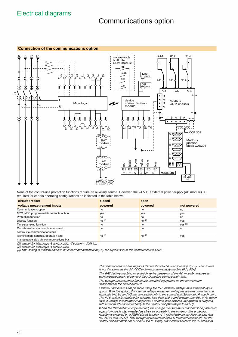
Communications option
Connection of the communications option
None of the control-unit protection functions require an auxiliary source. However, the 24 V DC external power-supply (AD module) isrequired for certain operating configurations as indicated in the table below.
circuit breaker closed openvoltage measurement inputs powered powered not powered
Communications option no no noM2C, M6C programmable contacts option yes yes yesProtection function no no noDisplay function no (1) no (2) yesTime-stamping function no no yes (3)
Circuit-breaker status indications and no no nocontrol via communications busIdentification, settings, operation and no (1) no (2) yesmaintenance aids via communications bus
(1) except for Micrologic A control units (if current < 20% In).(2) except for Micrologic A control units.(3) time setting is manual and can be carried out automatically by the supervisor via the communications bus.
The communications bus requires its own 24 V DC power source (E1, E2). This sourceis not the same as the 24 V DC external power-supply module (F1-, F2+).The BAT battery module, mounted in series upstream of the AD module, ensures anuninterrupted supply of power if the AD module power supply fails.The voltage measurement inputs are standard equipment on the downstreamconnectors of the circuit breaker.External connections are possible using the PTE external voltage measurement inputoption. With this option, the internal voltage measurement inputs are disconnected andterminals VN, V1 and V2 are connected only to the control unit (Micrologic P and H only).The PTE option is required for voltages less than 100 V and greater than 690 V (in whichcase a voltage transformer is required). For three-pole devices, the system is suppliedwith terminal VN connected only to the control unit (Micrologic P and H).When the PTE option is implemented, the voltage measurement input must be protectedagainst short-circuits. Installed as close as possible to the busbars, this protectionfunction is ensured by a P25M circuit breaker (1 A rating) with an auxiliary contact (cat.no. 21104 and 21117). This voltage measurement input is reserved exclusively for thecontrol unit and must not ever be used to supply other circuits outside the switchboard.
Electrical diagrams
71
5 4 3 2 1
PowermeterPowerLogic,Jbus, Modbus RXA RXB TXA TXB
Masterpact ACBModbus, Jbus
B´A´ B A
To otherPowerLogic,Jbus orModbus devices
IN+
IN-
OU
T+
SH
IELD
OU
T-
20 21 22 23 24
IN+
IN-
OU
T-O
UT
+
SH
IELD
CM2000PowerLogic
MCA485
Green RX+White RX-Red TX+Black TX-
Green RX+White RX-Red TX+Black TX-
Belden 8723
RS485 port
IC 108ARS 232/485
converterRS232 port
standard RS232 cable
RS232 port
SystemManagerSoftware
Bla
ckR
edW
hite
Gre
en
Rx+ Rx- Tx+ TX-
MCT485
PowerLogic
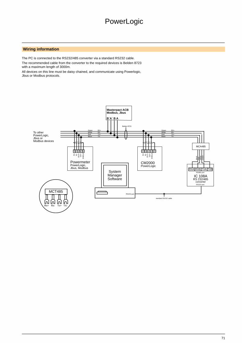
Wiring information
The PC is connected to the RS232/485 converter via a standard RS232 cable.
The recommended cable from the converter to the required devices is Belden 8723with a maximum length of 3000m.
All devices on this line must be daisy chained, and communicate using Powerlogic,Jbus or Modbus protocols.

72
Earth-fault and earth-leakageprotectionZone selective interlocking
External sensor (CT) for residual earth-fault protection
External transformer for source ground return (SGR) earth-fault protection
Connection of the secondary circuitMasterpact equipped with a Micrologic 6 A/P/H:c Unshielded cable with 1 twisted pair.c Maximum length 150 meters.c Cable cross-sectional area 0.4 to 1.5 mm2
c Terminals 5 and 6 may not be used at the same time.c Use terminal 5 for NW08 to 40.c Use terminal 6 for NW40b to 63.
Connection of current-transformer secondary circuitfor external neutralMasterpact equipped with a Micrologic 6 A/P/H:c Shielded cable with 2 twisted pairs.c SG1 twisted with SG2.c X1 twisted with X2.c Shielding connected to earth on one end only.c Maximum length 5 meters.c Cable cross-sectional area 0.4 to 1.5 mm2.
If the incoming supply is connected to the ACB via thebottom terminals, control and power wiring is identical(H1 connected to the source side, H2 to the loadside).
For four-pole versions, for residual earth-faultprotection, the current transformer for the externalneutral is not necessary.
If the 2000/6300 current transformer is used:c Signals SG1 and SG2 must be wired in series.c Signals X1 and X2 must be wired in parallel.
Connection for signal VN is required only for powermeasurements (3 Ø, 4 wires, 4CTs).c Ground terminal end of the neutral currenttransformer only. If no other ground exists in controlsystem (check NEC requirements and connect groundto equipment ground bars).
Electrical diagrams
T4
T3
T2
T1
Micrologic 6
Z4
Z3
Z2
Z1
Z5
VN
V1
V2
V3
M3
M2
M1
F2+
F1
I
U
Q
10 1176512
8
913 13 14
MDGF moduleX1
X2PE
H1
H2
or
Micrologic 6I
73
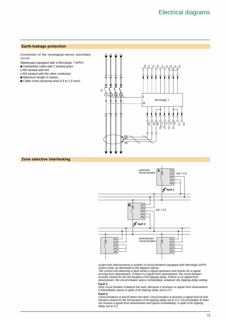
Connection of the rectangular-sensor secondarycircuit
Masterpact equipped with a Micrologic 7 A/P/H:c Unshielded cable with 2 twisted pairs:v M2 twisted with M3.v M1 twisted with the other conductor.c Maximum length 4 metres.c Cable cross-sectional area 0.4 to 1.5 mm2.
Earth-leakage protection
A pilot wire interconnects a number of circuit breakers equipped with Micrologic A/P/Hcontrol units, as illustrated in the diagram above.The control unit detecting a fault sends a signal upstream and checks for a signalarriving from downstream. If there is a signal from downstream, the circuit breakerremains closed for the full duration of its tripping delay. If there is no signal fromdownstream, the circuit breaker opens immediately, whatever the tripping-delay setting.Fault 1.Only circuit breaker A detects the fault. Because it receives no signal from downstream,it immediately opens in spite of its tripping delay set to 0.3.Fault 2.Circuit breakers A and B detect the fault. Circuit breaker A receives a signal from B andremains closed for the full duration of its tripping delay set to 0.3. Circuit breaker B doesnot receive a signal from downstream and opens immediately, in spite of its trippingdelay set to 0.2.
Zone selective interlocking
Z1Z2Z3Z4Z5
A
Z1Z2Z3Z4Z5
B
Z1Z2Z3Z4Z5
Z1Z2Z3Z4Z5
tsd = 0,3
tsd = 0,2
downstreamcircuit breaker
fault 1
fault 2
upstreamcircuit breaker
Electrical diagrams
T4
T3
T2
T1
Micrologic 7
Z4
Z3
Z2
Z1
Z5
VN
V1
V2
V3
M3
M2
M1
F2+
F1
I
U
Q
N L3L2L1
M1M2
M3

74

75
Installation recommendations
Product panarama 3Performance and functionality 11Dimensions and connection 45Electrical diagrams 65
Operating conditions 76Installation in switchboard 78Switchboard preparations 80Power connection 82Busbar drilling and sizing 84Temperature derating 87
Protection characteristics 89
Masterpact NW
76
Test
Test
Test
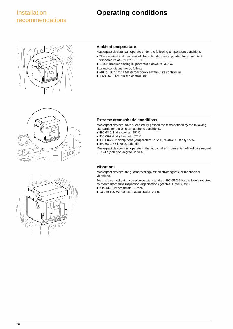
Ambient temperatureMasterpact devices can operate under the following temperature conditions:
c The electrical and mechanical characteristics are stipulated for an ambienttemperature of -5° C to +70° C.
c Circuit-breaker closing is guaranteed down to -35° C.
Storage conditions are as follows:c -40 to +85°C for a Masterpact device without its control unit.c -25°C to +85°C for the control unit.
Extreme atmospheric conditionsMasterpact devices have successfully passed the tests defined by the followingstandards for extreme atmospheric conditions:c IEC 68-2-1: dry cold at -55° C.c IEC 68-2-2: dry heat at +85° C.c IEC 68-2-30: damp heat (temperature +55° C, relative humidity 95%).c IEC 68-2-52 level 2: salt mist.
Masterpact devices can operate in the industrial environments defined by standardIEC 947 (pollution degree up to 4).
VibrationsMasterpact devices are guaranteed against electromagnetic or mechanicalvibrations.
Tests are carried out in compliance with standard IEC 68-2-6 for the levels requiredby merchant-marine inspection organisations (Veritas, Lloyd’s, etc.):c 2 to 13.2 Hz: amplitude ±1 mm.c 13.2 to 100 Hz: constant acceleration 0.7 g.
Operating conditionsInstallationrecommendations
77
2000
m
Test
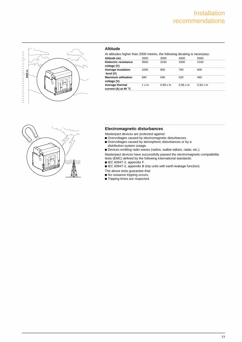
AltitudeAt altitudes higher than 2000 metres, the following derating is necessary:Altitude (m) 2000 3000 4000 5000Dielectric resistance 3500 3150 2500 2100voltage (V)Average insulation 1000 900 700 600 level (V)Maximum utilisation 690 590 520 460voltage (V)Average thermal 1 x In 0.99 x In 0.96 x In 0.94 x Incurrent (A) at 40 °C
Test
Electromagnetic disturbancesMasterpact devices are protected against:c Overvoltages caused by electromagnetic disturbances.c Overvoltages caused by atmospheric disturbances or by a
distribution-system outage.c Devices emitting radio waves (radios, walkie-talkies, radar, etc.).
Masterpact devices have successfully passed the electromagnetic-compatibilitytests (EMC) defined by the following international standards:c IEC 60947-2, appendix F.c IEC 60947-2, appendix B (trip units with earth-leakage function).
The above tests guarantee that:c No nuisance tripping occurs.c Tripping times are respected.
Installationrecommendations
78
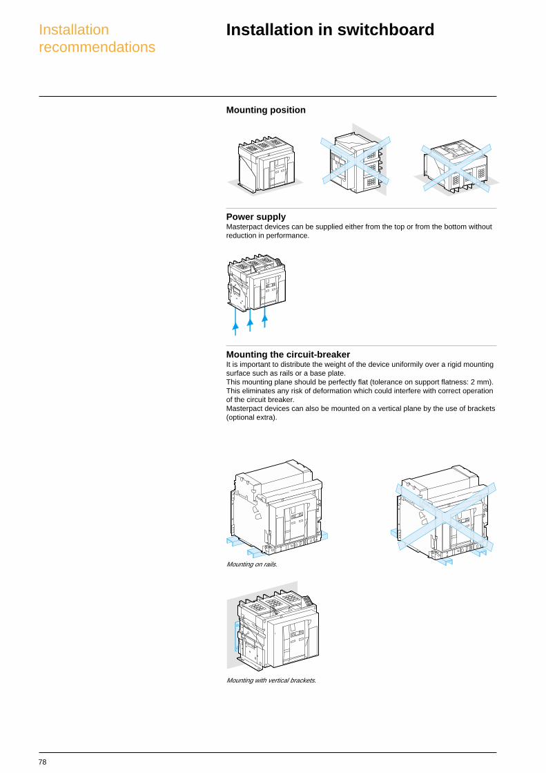
Mounting position
Power supplyMasterpact devices can be supplied either from the top or from the bottom withoutreduction in performance.
Installation in switchboard
Mounting the circuit-breakerIt is important to distribute the weight of the device uniformily over a rigid mountingsurface such as rails or a base plate.This mounting plane should be perfectly flat (tolerance on support flatness: 2 mm).This eliminates any risk of deformation which could interfere with correct operationof the circuit breaker.Masterpact devices can also be mounted on a vertical plane by the use of brackets(optional extra).
Mounting with vertical brackets.
Mounting on rails.
Installationrecommendations

79
Busbars and PartitionsWhere busbars and busbar connections pass throughmetal barriers care must be taken to eliminate thepossibility of forming a magnetic loop .
A : non magnetic material
E47
661A
A
Dimensions and weights Main dimensions in mm (H x W x D)Masterpact NW08/40 NW40b/63
drawout 3P 439 x 441 x 395 479 x 786 x 3954P 439 x 556 x 395 479 x 1016 x 395
fixed 3P 352 x 422 x 297 352 x 767 x 2974P 352 x 537 x 297 352 x 997 x 297
Weight (kg)Masterpact NW08/40 NW40b/63
drawout 3P 90 2254P 120 300
fixed 3P 60 1204P 80 160
non magneticmaterial
Installationrecommendations

80
Door interlock catch
Note: The door interlock can either be mounted on theright side or the left side of the breaker.F Datum.
Breaker in “connected” or “test” positionDoor cannot be opened
Breaker in “disconnected” positionDoor can be opened
Dimensions (mm)Type (1) (2)
NW08-40 (3P) 215 215NW08-40 (4P) 330 215NW40b-63 (3P) 660 215NW40b-63 (4P) 775 215
17
8
5
15
X
Y
(2) (1)
(1)
F
(2)
door
Dimensions (mm)Type (1) (2)
NW 83 103
Catch not supplied
Door interlock catchInstallationrecommendations

81
Cable-type door interlockConnection of MN, MX and XFvoltage releases
NW Cable-type door interlockThis option prevents door opening when the circuit breaker is closed and preventscircuit breaker closing when the door is open.For this, a special plate associated with a lock and a cable is mounted on the rightside of the circuit breaker.With this interlock installed, the source changeover function cannot beimplemented.
Wiring of voltage releasesDuring pick-up, the power consumed is approximately 150 to 200 VA. For lowcontrol voltages (12, 24, 48 V), maximum cable lengths are imposed by the voltageand the cross-sectional area of cables.
Recommanded maximum cable lengths (meter)12 V 24 V 48 V
2,5 mm2 1,5 mm2 2,5 mm2 1,5 mm2 2,5 mm2 1,5 mm2
MN U source 100 % – – 58 35 280 165U source 85 % – – 16 10 75 45
MX-XF U source 100 % 21 12 115 70 550 330U source 85 % 10 6 75 44 350 210
Note: the indicated length is that of each of the two wires
121
84
10
165
46
79 52
82
Power connection
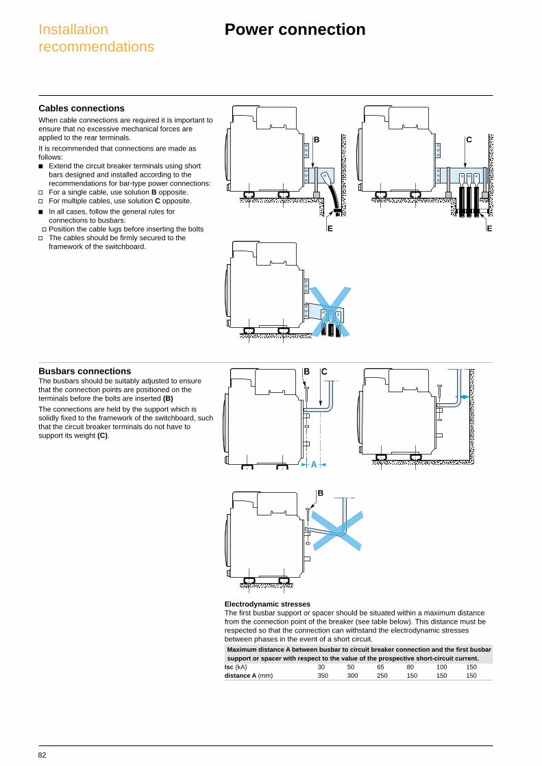
Busbars connectionsThe busbars should be suitably adjusted to ensurethat the connection points are positioned on theterminals before the bolts are inserted (B)The connections are held by the support which issolidly fixed to the framework of the switchboard, suchthat the circuit breaker terminals do not have tosupport its weight (C).
Cables connectionsWhen cable connections are required it is important toensure that no excessive mechanical forces areapplied to the rear terminals.
It is recommended that connections are made asfollows:c Extend the circuit breaker terminals using short
bars designed and installed according to therecommendations for bar-type power connections:
v For a single cable, use solution B opposite.v For multiple cables, use solution C opposite.
c In all cases, follow the general rules forconnections to busbars:
v Position the cable lugs before inserting the boltsv The cables should be firmly secured to the
framework of the switchboard.
A
B C
B
B
E
C
E
Electrodynamic stressesThe first busbar support or spacer should be situated within a maximum distancefrom the connection point of the breaker (see table below). This distance must berespected so that the connection can withstand the electrodynamic stressesbetween phases in the event of a short circuit.Maximum distance A between busbar to circuit breaker connection and the first busbarsupport or spacer with respect to the value of the prospective short-circuit current.
Isc (kA) 30 50 65 80 100 150distance A (mm) 350 300 250 150 150 150
Installationrecommendations
83
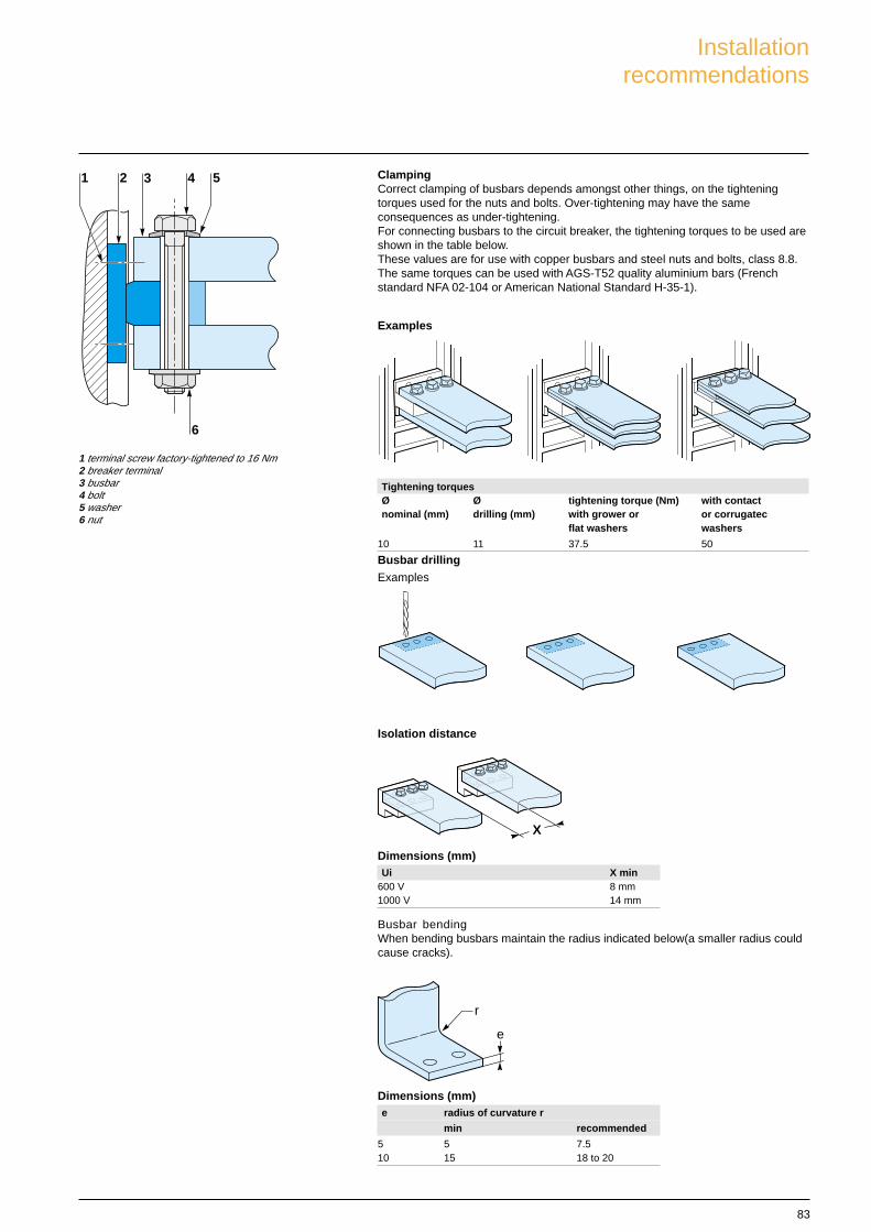
ClampingCorrect clamping of busbars depends amongst other things, on the tighteningtorques used for the nuts and bolts. Over-tightening may have the sameconsequences as under-tightening.For connecting busbars to the circuit breaker, the tightening torques to be used areshown in the table below.These values are for use with copper busbars and steel nuts and bolts, class 8.8.The same torques can be used with AGS-T52 quality aluminium bars (Frenchstandard NFA 02-104 or American National Standard H-35-1).
Tightening torquesØ Ø tightening torque (Nm) with contactnominal (mm) drilling (mm) with grower or or corrugatec
flat washers washers
10 11 37.5 50
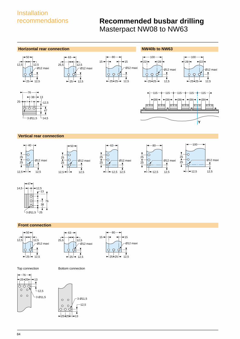
Busbar drillingExamples
Isolation distance
Busbar bendingWhen bending busbars maintain the radius indicated below(a smaller radius couldcause cracks).
4 532
6
1
e
r
X
Dimensions (mm)e radius of curvature r
min recommended
5 5 7.510 15 18 to 20
Examples
1 terminal screw factory-tightened to 16 Nm2 breaker terminal3 busbar4 bolt5 washer6 nut
Dimensions (mm)Ui X min
600 V 8 mm1000 V 14 mm
Installationrecommendations
84
Horizontal rear connection NW40b to NW63
==
76
13
25
3 Ø11,5
12,5
38
47
14,5
Y
115115115115115
3939 39 39 39
76
253 Ø11,5
38
12,513
47
14,5
=
=
12,5
25 25 13
3 Ø11,5
76
Recommended busbar drillingMasterpact NW08 to NW63
Vertical rear connection
Front connection
Top connection Bottom connection
12,5Ø12 maxi
25 12,5
50
12,5 25,5Ø12 maxi
25 12,5
63
12,515
Ø12 maxi
25 12,5
80
25
15 22
Ø12 maxi
25 12,5
100
25
28 28
Ø12 maxi
25 12,5
100
25
22
Ø12 maxi
12,5
40
25
12,5
25Ø12 maxi
12,5
50
25
12,5
25Ø12 maxi
12,5
63
25
12,5
25Ø12 maxi
12,5
80
25
12,5
25Ø12 maxi
12,5
100
25
12,5
25
12,5Ø12 maxi
25 12,5
50
12,5 25,5Ø12 maxi
25 12,5
63
12,515
Ø12 maxi
25 12,5
80
25
15
12,5
1325 25
3 Ø11,5
Installationrecommendations

85
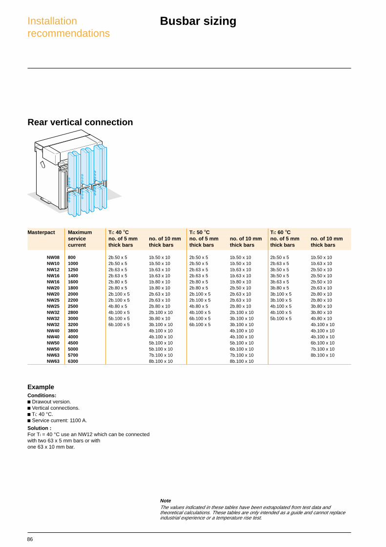
Busbar sizing
Basis of tables:c Maximum permissible busbars temperature: 100 °C.c Temperature inside the switchboard around the
circuit breaker and its connection: Ti (IEC 60947-2).c Busbar material is unpainted copper.
Masterpact Maximum Ti : 40 °C Ti : 50 °C Ti : 60 °Cservice no. of 5 mm no. of 10 mm no. of 5 mm no. of 10 mm no. of 5 mm no. of 10 mmcurrent thick bars thick bars thick bars thick bars thick bars thick bars
NW08 800 2b.50 x 5 1b.50 x 10 2b.50 x 5 1b.50 x 10 2b.50 x 5 1b.63 x 10NW10 1000 3b.50 x 5 1b.63 x 10 3b.50 x 5 2b.50 x 10 3b.63 x 5 2b.50 x 10NW12 1250 3b.50 x 5 2b.40 x 10 3b.50 x 5 2b.50 x 10 3b.63 x 5 2b.50 x 10
2b.80 x 5 2b.40 x 10 2b.80 x 5NW16 1400 3b.50 x 5 2b.40 x 10 2b.80 x 5 2b.50 x 10 3b.80 x 5 2b.63 x 10NW16 1600 3b.63 x 5 2b.50 x 10 3b.80 x 5 2b.63 x 10 3b.80 x 5 3b.50 x 10NW20 1800 3b.80 x 5 2b.63 x 10 3b.80 x 5 2b.63 x 10 3b.100 x 5 2b.80 x 10NW20 2000 3b.100 x 5 2b.80 x 10 3b.100 x 5 2b.80 x 10 3b.100 x 5 3b.63 x 10NW25 2200 3b.100 x 5 2b.80 x 10 3b.100 x 5 2b.80 x 10 4b.80 x 5 2b.100 x 10NW25 2500 4b.100 x 5 2b.100 x 10 4b.100 x 5 2b.100 x 10 4b.100 x 5 3b.80 x 10NW32 2800 4b.100 x 5 3b.80 x 10 4b.100 x 5 3b.80 x 10 5b.100 x 5 3b.100 x 10NW32 3000 5b.100 x 5 3b.80 x 10 6b.100 x 5 3b.100 x 10 8b.100 x 5 4b.80 x 10NW32 3200 6b.100 x 5 3b.100 x 10 8b.100 x 5 3b.100 x 10 4b.100 x 10NW40 3800 4b.100 x 10 5b.100 x 10 5b.100 x 10NW40 4000 5b.100 x 10 5b.100 x 10 6b.100 x 10NW50 4500 6b.100 x 10 6b.100 x 10 7b.100 x 10NW50 5000 7b.100 x 10 7b.100 x 10
ExampleConditions:c Drawout version.c Horizontal busbars.c Ti: 50 °C .c Service current: 1800 A.
Solution:For Ti = 50 °C, use an NW20 which can be connectedwith three 80x5 mm bars or two mm 63x10 bars.
Front or rear horizontal connection
NoteThe values indicated in these tables have been extrapolated from test data andtheoretical calculations. These tables are only intended as a guide and cannot replaceindustrial experience or a temperature rise test.
Installationrecommendations
86
Masterpact Maximum Ti: 40 °C Ti: 50 °C Ti: 60 °Cservice no. of 5 mm no. of 10 mm no. of 5 mm no. of 10 mm no. of 5 mm no. of 10 mmcurrent thick bars thick bars thick bars thick bars thick bars thick bars
NW08 800 2b.50 x 5 1b.50 x 10 2b.50 x 5 1b.50 x 10 2b.50 x 5 1b.50 x 10NW10 1000 2b.50 x 5 1b.50 x 10 2b.50 x 5 1b.50 x 10 2b.63 x 5 1b.63 x 10NW12 1250 2b.63 x 5 1b.63 x 10 2b.63 x 5 1b.63 x 10 3b.50 x 5 2b.50 x 10NW16 1400 2b.63 x 5 1b.63 x 10 2b.63 x 5 1b.63 x 10 3b.50 x 5 2b.50 x 10NW16 1600 2b.80 x 5 1b.80 x 10 2b.80 x 5 1b.80 x 10 3b.63 x 5 2b.50 x 10NW20 1800 2b.80 x 5 1b.80 x 10 2b.80 x 5 2b.50 x 10 3b.80 x 5 2b.63 x 10NW20 2000 2b.100 x 5 2b.63 x 10 2b.100 x 5 2b.63 x 10 3b.100 x 5 2b.80 x 10NW25 2200 2b.100 x 5 2b.63 x 10 2b.100 x 5 2b.63 x 10 3b.100 x 5 2b.80 x 10NW25 2500 4b.80 x 5 2b.80 x 10 4b.80 x 5 2b.80 x 10 4b.100 x 5 3b.80 x 10NW32 2800 4b.100 x 5 2b.100 x 10 4b.100 x 5 2b.100 x 10 4b.100 x 5 3b.80 x 10NW32 3000 5b.100 x 5 3b.80 x 10 6b.100 x 5 3b.100 x 10 5b.100 x 5 4b.80 x 10NW32 3200 6b.100 x 5 3b.100 x 10 6b.100 x 5 3b.100 x 10 4b.100 x 10NW40 3800 4b.100 x 10 4b.100 x 10 4b.100 x 10NW40 4000 4b.100 x 10 4b.100 x 10 4b.100 x 10NW50 4500 5b.100 x 10 5b.100 x 10 6b.100 x 10NW50 5000 5b.100 x 10 6b.100 x 10 7b.100 x 10NW63 5700 7b.100 x 10 7b.100 x 10 8b.100 x 10NW63 6300 8b.100 x 10 8b.100 x 10
ExampleConditions:c Drawout version.c Vertical connections.c Ti: 40 °C.c Service current: 1100 A.
Solution :For Ti = 40 °C use an NW12 which can be connectedwith two 63 x 5 mm bars or withone 63 x 10 mm bar.
Rear vertical connection
NoteThe values indicated in these tables have been extrapolated from test data andtheoretical calculations. These tables are only intended as a guide and cannot replaceindustrial experience or a temperature rise test.
Busbar sizingInstallationrecommendations

87
Version Drawout Fixed
Power dissipation (Watts) Input/output resistance (µohm) Power dissipation (Watts) Input/ouput resistance (µohm)
NW08 N1 137 42 62 19NW08 H/L 100 30 42 13NW10 N1 220 42 100 19NW10 H/L 150 30 70 13NW12 N1 330 42 150 19NW12 H/L 230 27 105 13NW16 N1 480 37 250 19NW16 H/L 390 27 170 13NW20 H/L 470 23 250 13NW25 H1/H2/H3 600 19 260 8NW32 H1/H2/H3 670 13 420 8NW40 H1/H2/H3 900 11 650 8NW40b H1/H2 380 7 270 5NW50 H1/H2 590 7 420 5NW63 H1/H2 950 7 660 5
Temperature derating
Temperature deratingThe table below indicates the maximum current rating,for each connection type, as a function of the ambienttemperature around the circuit breaker and thebusbars.
Circuit breakers with mixed connections have thesame derating as horizontally connected breakers.For ambient temperatures greater than 60 °C,consult us.Temperature inside the switchboard around the circuitbreaker and its connection: Ti (IEC 60947-2)
Power dissipation and input / outputresistanceTotal power dissipation is the value measured at IN,50/60 Hz, for a 3 pole or 4 pole breaker (values abovethe power P = I2R).The resistance between input / output is the valuemeasured per pole.
Version Drawout Fixed
Connection Front or rear horizontal Rear vertical Front or rear horizontal Rear vertical
temp. Ti 40 45 50 55 60 40 45 50 55 60 40 45 50 55 60 40 45 50 55 60
NW08 N/H/L 800 800 800 800NW10 N/H/L 1000 1000 1000 1000NW12 N/H/L 1250 1250 1250 1250NW16 N/H/L 1600 1600 1600 1600NW20 H1/H2/H3 2000 1980 1890 2000 2000 1920 2000NW20 L1 2000 1900 1850 1800 2000 – – – – – – – – – –NW25 H1/H2/H3 2500 2500 2500 2500NW32 H1/H2/H3 3200 3100 3000 2900 3200 3200 3100 3200NW40 H1/H2/H3 4000 3900 3750 3650 4000 3850 4000 3900 3800 4000
NW40b H1/H2 4000 4000 4000 4000NW50 H1/H2 5000 5000 5000 5000NW63 H1/H2 5900 5800 5600 5500 5300 6300 6200 6300 6300

88
89
Protection characteristics
Product panarama 3Performance and functionality 11Dimensions and connection details 45Electrical diagrams 65Installation recommendations 73
Tripping curves 90Limitation curves (current and Energy) 92
Masterpact NW
90
Ig = A…J x In (1) 1200 A max.
t(s)
I / In
10 0005 000
2 000
1 000
500
200
100
50
20
10
5
2
1
.5
.2
.1.05
.02
.01
.005
.002
.001.05.07 .1 .2 .3 .4 .5 .7 1 2 3 5 7 10 200 300
I2t OFF
0.4
0.30.20.1
I2t ON
0.4
0.30.20.1
0 0
Protectioncharacteristics
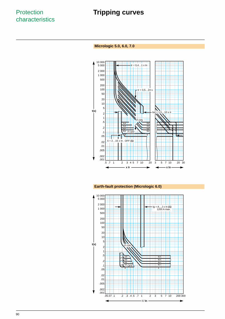
Tripping curves
Micrologic 5.0, 6.0, 7.0
0
0,4
0,3
0,20,1
t(s)
x In
tr = 0,5…24 s
Isd = 1,5…10 x Ir
Ir = 0,4…1 x In
Ii = 2…15 x In . OFF (1)
I2t OFF
x Ir
0,4
0,3
0,20,1
I2t ON
0
.5 .7 1 2 3 4 5 7 10 20 3 5 7 10 20 30
10 0005 000
2 000
1 000
500
200
100
50
20
10
5
2
1
.5
.2
.1.05
.02
.01
.005
.002
.001
Earth-fault protection (Micrologic 6.0)

91
DT
VIT
EIT
HVF
SIT
.5 .7 1 2 3 4 5 7 10 20
I / Ir
10 000
5 000
2 000
1 000
500
200
100
50
20
10
5
2
1
.5
100 000
t(s)
IDMTL curve (Micrologic P and H)
Protectioncharacteristics
92
Protectioncharacteristics
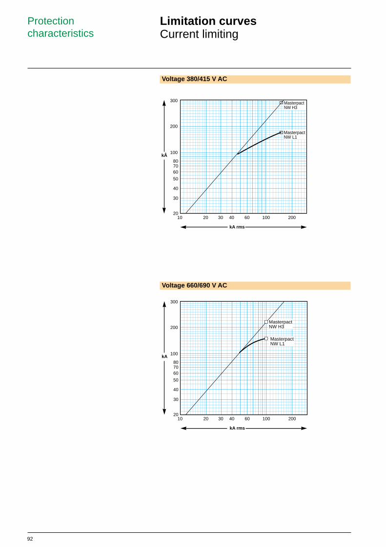
Voltage 660/690 V AC
10 20 30 40 60 100 20020
40
100
200
30
50
607080
300
kA
kA rms
MasterpactNW L1
MasterpactNW H3
Limitation curvesCurrent limiting
Voltage 380/415 V AC
10 20 30 40 60 100 20020
40
100
200
30
50
607080
300
kÂ
MasterpactNW H3
MasterpactNW L1
kA rms
93
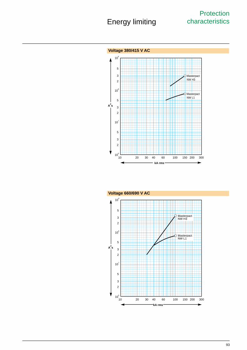
Voltage 380/415 V AC
Voltage 660/690 V AC
MasterpactNW L1
MasterpactNW H3
A2s
10 20 30 40 60 100 200 300
2
3
5
2
3
5
2
3
5
106
150
107
108
109
kA rms
A2s
10 20 30 40 60 100 200 300
2
3
5
2
3
5
2
3
5
106
150
107
108
109
MasterpactNW L1
MasterpactNW H3
kA rms
ProtectioncharacteristicsEnergy limiting

94
Schneider ElectricAn overview
Schneider Electrics expertise is founded on itsthree international brands – Merlin Gerin, Square Dand Telemecanique.
With over 100 years experience in the electrical industry,Schneider Electric has established itself as a world and UK leaderin the supply and manufacture of products for the distribution,monitoring and control of electrical power.
Schneider Electric regards its customers as commercial partners,who, like us, demand the highest standards of excellence in termsof products, projects and services.
Schneider Electric is proud to provide the solutions to meet theirneeds.
Schneider Electric operates the largest, dedicated sales force in the UKelectrical industry.
Sales engineers have specialist expertise and an understanding of the customer needswithin each of the following market sectors:
■ Building systems and solutions
■ Industrial systems and solutions
■ Energy and infrastructure systems andsolutions

95
Schneider ElectricAn overview
Building systems and solutions
Schneider Electric means greater comfort, lower operating costs and enhanced safety.
Related industries
■ Retail
■ Education
■ Health
■ Entertainment centres
■ Offices
■ Warehouses
■ Agriculture
■ Factory
■ Private residential
■ Public residential
The real reason for putting technology intobuildings is to simplify tasks, enhance safety andimprove the quality of life.
Schneider Electric knows this and has created attractive,functional products for the residential building sector. Well beingcomfort and entertainment are key concepts in this area.
The same objectives apply to commercial buildings such asoffices, hotels, shopping centres, hospitals, schools and carefacilities for the elderly.
Schneider Electric offer a wide range of solutions in the area ofbuilding management services and uses its expertise in all ofthese buildings to protect people and equipment.
Principal customers in the construction market
■ Contracting authorities
■ Main contractors
■ Building engineers

96
Schneider ElectricAn overview
Industrial systems and solutions
Schneider Electric focus on performance in all areas of industry.
Our products and services adapt to each specific business and environment, fromdiscrete manufacturing and production lines to continuous processes in a wide variety ofindustries such as:
■ Automotive
■ Food and beverage
■ Pharmaceuticals
■ Construction materials
■ Waste management
Across a wide range of applications including:
■ Conveyors
■ Packaging
■ Materials handling
■ Hoisting

97
Schneider ElectricAn overview
Energy and infrastructure systems and solutions
Schneider Electric is involved in the entire electrical distribution chainfrom power plants to end users. Customer demand for completeavailability, uncompromising quality and absolute safety has made thesearch for excellence our key mission.
Today, electrical substation and network protection, monitoring and control are highlyeffective in reducing outage time.
Proven technologies offer a wide range of simple, efficient and flexible solutions foroptimised, step by step investments.
Principal customers in the electric power market
■ Power suppliers involved in generation and distribution
■ Utility companies
■ Major contractors
■ Large end user sites
■ Government departments
Key markets
■ Electricity distribution
■ Water
■ Rail
■ Airports
■ Seaports
■ Defence
■ Gas
■ Telecommunications
■ Road
Infrastructure
Schneider Electric is involved in developing infrastructure andtransportation systems around the world. In areas where nofailures can be tolerated, such as road and rail equipment,harbour installations and airports, Schneider Electric providessolutions in electrical distribution, control and monitoring,automation and supervision.

98
Choice of servicesOur services aim to add value to each project phase, butthe choice of services you use is entirely yours. You maywant a full set of services that together provide a packageof support covering the entire lifecycle of your project, oryou can select a combination of services to complementyour resources or knowledge.
If you are not sure of what you need, our consultationservices will help you to define the parameters of your
solution.
ConsultationThese services provide you with an assured way to roadmap your project. We take your ideas and requirementsand apply our wide range of application experience andtechnical competence to produce conceptual designs andindicative costings.
DesignUsing the analysis from the consultation phase, or
information that you may provide, the design phase selectsthe most suitable equipment and provides detailed
drawings and technical specifications.
ImplementationThis is often the most time-pressured stage of a projectwhen schedules demand fast implementation andcommissioning. These services provide high qualityinstallation and commissioning, preceded by thorough
preparation.
OperationEfficient operation is vital to derive the best value from yourinvestment. These services ensure that installations achievethe highest operational efficiency and are cost-effectively
maintained with minimum downtime.
ModernisationFaulty or ageing equipment can be refurbished andrepaired if this is the most cost-effective action.
TrainingA wide range of training services are available includingproduct standards and legislation. Each is regularlyupdated to stay current with the latest technology. Trainingcan be delivered at a Schneider Electric training facility, orat a customer’s own site.
Schneider ElectricAn overview
Projects and Services - delivering tailored solutions for your business
We provide solutions enabling you to reduce the totalcost and lifetime ownership risk of your electricaldistribution and automation systems, whilst fulfiling yourongoing quality, safety and environmental obligations.

99
Please note: Due to the constant progress in standards and equipment, the characteristics shown in the texts and images in this document are onlybinding once expressly confirmed by ourselves

Enclosed switch disconnectors
Merlin Gerin is a world leader in the manufacture and supply of high, medium and low voltage products for the distribution, protection, control and management of electrical systems and is focused on the needs of both thecommercial and industrial sectors. The newly launched VDINetwork Solutions offer provides flexible, configurableethernet systems for all communication needs.
Square D is a total quality organisation and its business is to put electricity to work productively and effectively, protecting people, buildings and equipment. Its low voltageelectrical distribution equipment, systems and services areused extensively in residential and commercial applications.
Telemecanique is a UK market leader and world expert inautomation and control. It provides complete solutions, withit's range of components, Modicon range of high technologyprogrammable controllers (PLCs), multiple fieldbus andethernet communication networks, HMI, motion controlsystems, variable speed drives and communicationssoftware. In addition, it offers power distribution throughprefabricated busbar trunking.
Schneider Electric’s local supportSchneider Electric is committed to supporting its customers at every stage of a project. Our 180 sales engineers, the largestdedicated sales force in the UK electrical industry, operate from 4 customer support centres.
Our sales engineers are skilled at assessing individual requirements and combined with the expert support of our product specialists, will develop the most effective and economical answer taking relevant regulations and standards fully into account.
To access the expertise of the Schneider Electric group, please call 0870 608 8 608. Each customer support centre includesfacilities for demonstrations and training, and presentation rooms fully equipped with audio visual and video, providing excellent meeting facilities.
www.schneider.co.uk
JAN 2005MGMV 5173.V2
Industrial systems and solutions showroomSchneider Electric Ltd, University of Warwick Science Park, Sir William Lyons Road, Coventry CV4 7EZ
Building systems and solutions showroomSchneider Electric Ltd, Stafford Park 5, Telford, Shropshire TF3 3BL
Energy and Infrastructure systems and solutions showroomSchneider Electric Ltd, 123 Jack Lane, Hunslet, Leeds LS10 1BS
Product showrooms
Fax 0870 608 8 6060870 608 8 608Nationwide support on one number - call the Customer Information Centre on
ScotlandSchneider Electric LtdUnit 11000Academy Business ParkGower StreetGlasgow G51 1PR
South WestSchneider Electric LtdPO Box 41Langley RoadChippenhamWiltshire SN51 1JJ
North WestSchneider Electric Ltd8 Brindley RoadCity Park Business VillageCornbrook Manchester M16 9HQ
Local customer support centres
member of
.co.uk
Related Documents