University of Liège Faculty of Applied Sciences Department of Electrical Engineering and Computer Science Master thesis Model-based-design to develop sensorless fan by Anaïs Halin Supervised by Prof. Christophe Geuzaine and Marc Lambrechts Master thesis submitted in partial fulfillment of the requirements for the Degree of Master of Science in Electrical Engineering Academic year 2016-2017

Welcome message from author
This document is posted to help you gain knowledge. Please leave a comment to let me know what you think about it! Share it to your friends and learn new things together.
Transcript

University of LiègeFaculty of Applied Sciences
Department of Electrical Engineering and Computer Science
Master thesis
Model-based-design to develop
sensorless fan
by Anaïs Halin
Supervised by Prof. Christophe Geuzaine and Marc Lambrechts
Master thesis submitted in partial fulfillment of the requirements for theDegree of Master of Science in Electrical Engineering
Academic year 2016-2017

Model-based-design to develop sensorless fan
Anaïs Halin,supervised by Prof. Christophe Geuzaine and Marc Lambrechts
Electrical EngineeringUniversity of Liège
Academic year 2016-2017
Abstract
Melexis specializes in developing robust sensorless actuators integrated circuits for au-tomotive applications like water-oil-fuel pumps, engine cooling fans and hvac (heating,ventilating, and air conditioning) blowers.
This master thesis intends for the iterative development of a realistic electro-mechanicalsystem model for existing hvac blowers, controlled without sensors (sensorless controlloop), via electronics that measure motor current and motor voltage (self-sensing solu-tion). It aims to predict the behavior of the fan for various control algorithms. Purposeis to accelerate future designs with efficient and robust control algorithms for self-sensingfans and pumps.
In order to reach these objectives, the first step is to select the modelling tool, then tocreate a model (first in open-loop, then in closed-loop) with available BLDC (brush-less direct current) motor systems knowhow from Melexis application engineers. Thisis done by performing iterative fitting with real system behaviour and simplifying themodel to the essence.
Furthermore, this document presents a way to find the electrical and mechanical motor’sparameters which are necessary to run the model. Finally, the model allowed to performa parametric analysis for hvac blowers enabling to better understand the key parametersinfluencing the behavior of such systems.
i

Figure 1: hvac blower fan used in the air conditioning system of a car.
Figure 2: Equivalent circuit of a BLDC motor for one of its phases. The followingassumptions are considered: the motor is not saturated; stator resistances of all thewindings are equal (RS), self inductances are constant (LS) and mutual inductances(M) are zero; iron losses are negligible.
Figure 3: Window of the Graphical User Interface (GUI). On the left part of the windoware the parameters of the simulation and the pushbutton to run the model. On theother side, the results are displayed and the data to plot can be chosen via a popupmenu.
ii

Acknowledgements
I would like to thank everyone who supported me throughout this master thesis, Iam thankful for the time you all have dedicated to me.
I would especially like to express my gratitude to my supervisors Professor ChristopheGeuzaine and Marc Lambrechts.
I also thank Melexis for having welcomed me.
Finally, I would like to thank all the Professors of the Faculty of Applied Sciences,and especially the Professors who agreed to be part of my jury.
Anaïs Halin
iii

Contents
List of Abbreviations vii
List of Symbols viii
1 Introduction 11.1 Overview . . . . . . . . . . . . . . . . . . . . . . . . . . . . . . . . . . . 2
2 Background 32.1 BLDC motors . . . . . . . . . . . . . . . . . . . . . . . . . . . . . . . . 32.2 Mathematical model . . . . . . . . . . . . . . . . . . . . . . . . . . . . 62.3 Reference frames . . . . . . . . . . . . . . . . . . . . . . . . . . . . . . 82.4 Cogging torque . . . . . . . . . . . . . . . . . . . . . . . . . . . . . . . 10
3 Open-loop modelling 123.1 Electrical part . . . . . . . . . . . . . . . . . . . . . . . . . . . . . . . . 123.2 Mechanical part . . . . . . . . . . . . . . . . . . . . . . . . . . . . . . . 133.3 Electro-mechanical part . . . . . . . . . . . . . . . . . . . . . . . . . . 143.4 Open-loop model . . . . . . . . . . . . . . . . . . . . . . . . . . . . . . 15
4 Closed-loop modelling 174.1 PID controller . . . . . . . . . . . . . . . . . . . . . . . . . . . . . . . . 174.2 PID parameters . . . . . . . . . . . . . . . . . . . . . . . . . . . . . . . 214.3 Selection of the target . . . . . . . . . . . . . . . . . . . . . . . . . . . 214.4 Influence of the number of steps . . . . . . . . . . . . . . . . . . . . . . 22
5 Simulation 245.1 Graphical User Interface . . . . . . . . . . . . . . . . . . . . . . . . . . 245.2 Results in Open-loop . . . . . . . . . . . . . . . . . . . . . . . . . . . . 26
iv
5.2.1 Current, back-emf and voltage . . . . . . . . . . . . . . . . . . . 265.2.2 Position and speed of rotor and voltage . . . . . . . . . . . . . . 285.2.3 Torques . . . . . . . . . . . . . . . . . . . . . . . . . . . . . . . 295.2.4 VB-, IV-, and IB-angles . . . . . . . . . . . . . . . . . . . . . . 305.2.5 Electromechanical power balance . . . . . . . . . . . . . . . . . 315.2.6 Phasor diagram GUI . . . . . . . . . . . . . . . . . . . . . . . . 325.2.7 Frequency sweep . . . . . . . . . . . . . . . . . . . . . . . . . . 335.2.8 Cogging torque . . . . . . . . . . . . . . . . . . . . . . . . . . . 355.2.9 Torque shock . . . . . . . . . . . . . . . . . . . . . . . . . . . . 37
5.3 Results in Closed-loop . . . . . . . . . . . . . . . . . . . . . . . . . . . 37
6 Open-loop electrical system characterization 416.1 Motor pole pairs . . . . . . . . . . . . . . . . . . . . . . . . . . . . . . 416.2 Back-emf constant . . . . . . . . . . . . . . . . . . . . . . . . . . . . . 426.3 Resistance and inductance of the motor . . . . . . . . . . . . . . . . . . 44
6.3.1 Approximate method . . . . . . . . . . . . . . . . . . . . . . . . 45
7 Open-loop mechanical system characterization 497.1 Friction parameter . . . . . . . . . . . . . . . . . . . . . . . . . . . . . 497.2 Inertia . . . . . . . . . . . . . . . . . . . . . . . . . . . . . . . . . . . . 51
8 Electrical parametric analysis 548.1 Resistance . . . . . . . . . . . . . . . . . . . . . . . . . . . . . . . . . . 548.2 Inductance . . . . . . . . . . . . . . . . . . . . . . . . . . . . . . . . . . 558.3 Motor constant . . . . . . . . . . . . . . . . . . . . . . . . . . . . . . . 55
9 Mechanical parametric analysis 589.1 Inertia . . . . . . . . . . . . . . . . . . . . . . . . . . . . . . . . . . . . 589.2 Friction and load of the motor . . . . . . . . . . . . . . . . . . . . . . . 599.3 Other parameters . . . . . . . . . . . . . . . . . . . . . . . . . . . . . . 59
10 Conclusion 6210.1 Future work . . . . . . . . . . . . . . . . . . . . . . . . . . . . . . . . . 63
Appendices 64
v

A Strategy of Melexis 65A.1 About Melexis . . . . . . . . . . . . . . . . . . . . . . . . . . . . . . . . 65
A.1.1 Corporate governance . . . . . . . . . . . . . . . . . . . . . . . . 66A.2 Strategy . . . . . . . . . . . . . . . . . . . . . . . . . . . . . . . . . . . 67
A.2.1 R&D strategy . . . . . . . . . . . . . . . . . . . . . . . . . . . . 68A.2.2 HR strategy . . . . . . . . . . . . . . . . . . . . . . . . . . . . . 68
B Parameter data set 70
Bibliography 75
vi
List of Abbreviations
BEMF back electromotive force.
BLDC brushless direct current.
DC direct current.
EMF electromotive force.
GUI graphical user interface.
HVAC heating, ventilating, and air conditioning.
IC integrated circuit.
PM permanent magnet.
PMSM permanent magnet DC synchronous motor.
RMS root mean square.
RPM revolutions per minute.
vii

List of Symbols
E back-emf.
ea, eb, ec phase back-emf.
I current.
ia, ib, ic phase currents.
iα, iβ alpha and beta currents.
id, iq direct and quadrature currents.
J inertia.
Ke motor constant (translation rotation speed to back-emf).
KT motor constant (translation current to torque).
L self-inductance.
Ω rotor acceleration.
ω rotor angular speed.
p number of pole pairs.
R resistance.
t time.
θe electrical rotor angle.
viii

θm mechanical rotor angle.
T e electromagnetic torque.
T f friction torque.
T l load torque.
V DC voltage.
va, vb, vc phase voltages.
ix
Chapter 1
Introduction
This master thesis was linked to an internship within the Belgian Micro-ElectronicIntegrated Systems Company, Melexis N.V. Melexis, as its name suggests, is a globalsupplier of micro-electronic semiconductor solutions. Among a wide range of product,the Company specializes in developing robust sensorless actuators IC’s for automotiveapplications like water-oil-fuel pumps, engine cooling fans and hvac blowers. The appli-cation engineers of the Business Unit Actuators develop new products and find solutionsfor the customer needs. They work in a very pratical way. Their ultimate goal is tomake a product work.
The aim of this master thesis is to develop a realistic electro-mechanical system modelthat can predict the behavior of hvac blowers. The model can thus be used as a mod-elling tool to answer "what if" questions or explain theoriticaly some behaviors. Thesecond objective is to investigate how to identify the model electrical and mechanicalparameters. Finally, a parametric analysis shows the influence of electrical and mechan-ical parameters on motor systems. Purpose of the thesis is to start model-based-designfor motor control in Melexis:
• starting from Matlab-Simulink simulations for sensorless BLDC control
• generating software routines from this control model to include in Melexis’ em-bedded motor control IC’s
in order to accelerate future designs with efficient and robust control algorithms for self-sensing fans and pumps. Currently, they prototype the application directly on the chip,
1

using user-intensive embedded software development and iterations of trial - testing -correcting.
In order to reach these objectives, the first step is to select the modelling tool. Thismaster thesis has been entirely performed using Matlab. The second step is to deriveand implement a mathematical model in open-loop and in closed-loop. This will be doneby performing iterative fitting with real system behaviour and simplifying the model tothe essence. Despite the name, BLDC motors are actually a type of permanent magnetsynchronous motors (PMSM).
High efficiency and low noise are key requirements for fan systems. A control strategybased on motor current and voltage measurements (IV measurements) can be appliedwhich leads to high efficiency. The brushless 3-phase motors are controlled withoutsensors, via electronics that measure motor current and motor voltage (self-sensingsolution). Sinusoidal phase currents, in turn, contribute to smooth torque, and hence,low noise.
1.1 Overview
Firstly a literature study in the relevant areas was performed. Chapter 2 describesthe background. A model of BLDC motors is first achieved in open-loop in Chapter 3.Then a closed-loop model is implemented following different scenarios and algorithmsin Chapter 4. The GUI (Graphical User Interface) is presented in Chapter 5, in whichresults of the simulation are also given and analyzed. Open-loop electrical and mechan-ical systems are characterized in Chapter 6 and Chapter 7. These chapters allow toidentify the model parameters. Electrical and mechanical parametric analysis are per-formed in Chapter 8 and Chapter 9, giving the impact of parameters on the behaviorof the system. Conclusions are drawn in Chapter 10 along with future work recom-mendations. Finally, Appendix A is a non-technical chapter dedicated to the strategyaspects of Melexis.
2

Chapter 2
Background
The following chapter is theoretical about BLDC motors and its mathematical mod-elling. It also presents the reference frames used in this work, and finally defines thecogging torque.
2.1 BLDC motors
The brushless DC motor (BLDC) is a synchronous electric motor which, from amodelling perspective, looks like a DC motor. It exhibits a linear relationship on theone hand between current and torque, and on the other hand between back-emf androtation speed. It is an electronically controlled commutation system, while brushedmotors have a mechanical commutation. Additionally, the electromagnets do not move,and the permanent magnets rotate. A diagram of the BLDC motor is shown, onFigure 2.1.
Figure 2.1: BLDC motor cross section. Source: [15].
3

It is constructed with a permanent magnet rotor and a stator made out of laminatedsteel stacked up to carry windings. Electrical energy is converted to mechanical energyby the magnetic attractive forces between the permanent magnet rotor and a rotatingmagnetic field induced in the stator [4]. Therefore, motor operation is based on theattraction or repulsion between magnetic poles.
BLDC motors have many advantages over brushed DC motors and induction motors.Better speed versus torque characteristics, high dynamic response, high efficiency andreliability, long operating life, and noiseless operation are some of their pros.
There are two types of permanent magnet brushless DC motors which depend on theirback-emf waveforms. One has a stator winding which is trapezoidally wound to producea trapezoidal (six-step) back-emf (back-electromotive force) waveform. The other onehas a sinusoidally distributed winding with sinusoidal back-emf. Sometimes, the firstone is referred to as BLDC motor while the second is called PMSM (Permanent MagnetSynchronous Motor). Star wound motors with sinusoidal waveforms are consideredhereafter but BLDC motors and PMSM’s will be used interchangeably to refer to thiskind of motors.
The control of BLDC motors can be done in sensor or sensorless mode. The advantageof sensorless BLDC motor control is that the sensing part can be omitted, and thusoverall costs and size can be reduced. However, the disadvantages of sensorless controlare the higher requirements for control algorithms and more complicated electronics [5].
In order to obtain a noiseless operation, a constant torque is desired. The torque of theBLDC motor is mainly influenced by the waveform of back-emf (the voltage induced intothe stator winding due to rotor movement) and a sinusoidal motor produces smootherelectromagnetic torque than a trapezoidal motor. Moreover it can be shown that evenif there is a phase shift between voltage and back-emf, the torque is a constant insteady-state.
A three-phase inverter is used to drive the three-phase BLDC motor as illustrated onFigure 2.2. It is indeed electrically commutated by power switches instead of brushes.The easiest way to commutate a BLDC motor is the trapezoidal commutation. Thegenerated torque has a considerable torque ripple which occurs at each step of the
4

trapezoidal (or six-step) commutation. The six-step commutation typically energizestwo motor phase windings at any commutation sequence. It uses 6 distinct steps (i.e. 6positions per 360 electrical degrees), each according to an angle of 60 electrical turningangle. The control is based on position feedback. According to the position of the rotor,the inverter is in one of its 6 states. The main advantage of the trapezoidal commutationscheme is its simplicity. The downside is a torque ripple, especially at low speeds.
Figure 2.2: BLDC motor drive circuit, composed of the three-phase bldc motor and aninverter circuit (three-phase full-bridge structure). Source: [1].
An alternative to the simple trapezoidal commutation is to energize all three phaseswith sinusoidal currents. That means that the flat peaks that show up in the currentwaveform with trapezoidal commutation are replaced by sinusoidally shaped waveforms.In addition, all three phases are continuously energized, while with trapezoidal com-mutation, one phase is always off. That gives much smoother torque generation andenables more precise control. However, to generate a current waveform which is closeto sinusoidal, a continuous position calculation is necessary. A finer resolution thanthe 60 which suffices for trapezoidal commutation is needed. Indeed, a resolution inthe range of one degree is reasonable but the finer the resolution, the more precise thecontrol [7].
5
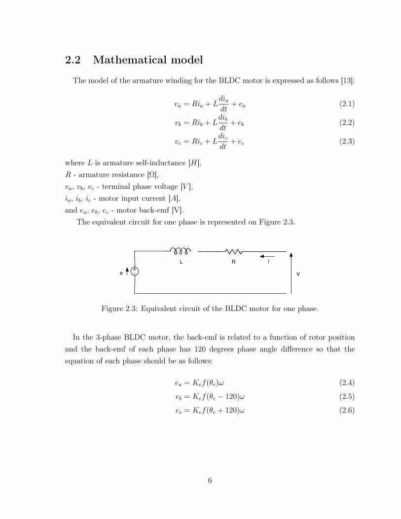
2.2 Mathematical model
The model of the armature winding for the BLDC motor is expressed as follows [13]:
va = Ria + Ldiadt
+ ea (2.1)
vb = Rib + Ldibdt
+ eb (2.2)
vc = Ric + Ldicdt
+ ec (2.3)
where L is armature self-inductance [H],R - armature resistance [Ω],va, vb, vc - terminal phase voltage [V ],ia, ib, ic - motor input current [A],and ea, eb, ec - motor back-emf [V].
The equivalent circuit for one phase is represented on Figure 2.3.
+-
RL
e V
i
Figure 2.3: Equivalent circuit of the BLDC motor for one phase.
In the 3-phase BLDC motor, the back-emf is related to a function of rotor positionand the back-emf of each phase has 120 degrees phase angle difference so that theequation of each phase should be as follows:
ea = Kef(θe)ω (2.4)
eb = Kef(θe − 120)ω (2.5)
ec = Kef(θe + 120)ω (2.6)
6
where Ke is back-emf constant [V/m−RPM ]1,θe - electrical rotor angle [e− degrees],ω - rotor speed [m−RPM ].
The electrical rotor angle is equal to the mechanical rotor angle multiplied by thenumber of pole pairs p:
θe = pθm (2.7)
where θm is mechanical rotor angle [m− degrees].
The total torque output can be represented as a summation of that of each phase.Next equation represents the total torque output, or electromagnetic torque:
Te =eaia + ebib + ecic
ω= KT
3
2iq (2.8)
where Te is total torque output [Nm],KT - motor constant [Nm/A],iq - quadrature current [A].
The equation of the mechanical part is represented as follows:
Te − Tl = Jdω
dt+ Tf (2.9)
where Tl is load torque [Nm],J - inertia of rotor and coupled shaft [kgm2],Tf - friction torque [Nm].
1The back-emf constant is expressed in volts per mechanical RPM (revolutions per minute). Them− and e− symbols before a unit respectively means mechanical and electrical referring to mechanicaland electrical angles which are linked by the number of pole pairs as in (2.7).
7

2.3 Reference frames
Different reference frames are used in the modelling in order to simplify some electro-magnetic equations and express phase currents, direct and quadrature currents in themost consistent way. Three reference frames, illustrated on Figure 2.4, are defined :
• a three-phase reference frame (a,b,c),
• a two-phase reference frame (α,β),
• a rotating reference frame (d,q).
The α,β frame is fixed to the stator, while the d,q frame is fixed to the rotor.
Figure 2.4: Different reference frames. Source: [12].
The three-phase currents ia, ib and ic are in the fixed three-phase reference frame,composed of the three axes A, B and C at an angle of 120 degrees to each other. TheClarke transform uses the three-phase currents ia, ib and ic to calculate currents in thetwo-phase orthogonal stator axis: iα and iβ. These two currents in the fixed coordinatestator phase are transformed to the id and iq currents components in the d,q frame withthe Park transform.
The iα (along α-axis) and iβ (along β-axis) currents are perpendicular to each otherand expressed in the orthogonal stationary reference frame. They can be obtained fromthe phase-currents in the following way:
iα =2
3· (ia −
1
2ib −
1
2ic) (2.10)
iβ =2
3· (√
3
2ib −
√3
2ic) (2.11)
8

or in a matrix representation
[iα(t)
iβ(t)
]=
2
3
[1 −1
2−1
2
0√32−√32
]ia(t)ib(t)
ic(t)
(2.12)
The Clarke’s transformation (also known as the alpha-beta transformation), definedin (2.12), preserves the amplitude of the electrical variables it is applied to. Indeed,considering a three-phase symmetric, direct, current sequence
ia(t) =√
2I cos(θ(t))
ib(t) =√
2I cos(θ(t)− 120)
ic(t) =√
2I cos(θ(t) + 120)
where I is the rms of ia, ib, ic, to which the transformation is applied, it results in
iα(t) =√
2I cos(θ(t))
iβ(t) =√
2I sin(θ(t))
Direct and quadrature currents, id and iq, use a frame of reference on the rotor. Asillustrated on Figure 2.4, iq is 90 degrees further than id and they rotate at the speedof the rotor so that id has an angle equal to the rotor angle θ with the α-axis. The idand iq currents can be computed as follows:
id = iα cos(θ) + iβ sin(θ)
iq = iβ cos(θ)− iα sin(θ)
or in a matrix representation[id
iq
]=
[cos(θ) sin(θ)
− sin(θ) cos(θ)
][iα
iβ
](2.13)
9

The direct and quadrature currents, id and iq, can also be expressed in terms of thephase currents ia, ib and ic, defining the Park’s transformation:
[id
iq
]=
2
3
[cos(θ) cos(θ − 120) cos(θ + 120)
− sin(θ) − sin(θ − 120) − sin(θ + 120)
]ia(t)ib(t)
ic(t)
(2.14)
The amplitude of the current (or peak current) can be obtained as follows :
I =√i2d + i2q
=√i2α + i2β
2.4 Cogging torque
The cogging torque of electrical motors is the torque due to the interaction betweenthe permanent magnets of the rotor and the stator slots. The construction of a slottedmotor is shown on Figure 2.5.
Figure 2.5: Construction of a slotted motor. Source: [3].
This torque is position dependent and its periodicity per revolution depends onthe number of magnetic poles and the number of teeth on the stator as illustrated onFigure 2.6.
10

Figure 2.6: Typical cogging torque waveform. Tc is the cogging torque and Nc is theperiod per revolution. Source: [16].
It manifests itself by the tendency of a rotor to align in a number of stable positionseven when the machine is unexcited. The cogging torque is an undesirable effect thatprevents the smooth rotation of the rotor and results in noise. It is especially prominentat lower speeds. It results in torque as well as speed ripples. At high speed, the motormoment of inertia filters out the effect of cogging torque2.
As illustrated on Figure 2.7, each tooth of the stator is strongly attracted to eachpassing PM pole. There are two positions of the rotor pole which will result in a zerocogging torque. The first one is when the PM pole is centered on a stator tooth. Thisis a stable point: if the rotor is moved from this position, a restoring torque will occurand the magnet will attempt to reestablish this position. The second one is centered atthe transition between two teeth. This is an unstable point: if the rotor is moved fromthis position, a non-restoring torque will develop and the magnet will seek to departfrom this position and be attracted by the nearest tooth center [6].
Figure 2.7: Cogging effect in a slotted motor. Source: [3].
2The mechanical part of the motor can be represented as a low-pass filter where the inertia is acapacitor and the friction a resistance, which explains why the high frequency components of a torqueare filtered out.
11

Chapter 3
Open-loop modelling
This chapter deals with the open-loop modelling of BLDC motors. The model is im-plemented on Matlab using ode45.
The model is focusing on hvac blowers with the following assumptions:
• sinusoidal back-emf,
• balanced system where all three phases have equal impedance values: ia(t) +
ib(t) + ic(t) = 0, Ra = Rb = Rc and La = Lb = Lc
• friction/load of the type: T = a ∗ ω2 + b ∗ ω + c, where a, b and c are constants.
The model is built step by step. For this purpose, it is divided into three consistentparts: the electrical, the mechanical and the electro-mechanical parts.
3.1 Electrical part
The main purpose here is to estimate the shape and the amplitude of the back-emf.It is given for each phase by (2.4), (2.5) and (2.6), where f(θe) is a sinusoidal function(according to the assumptions), which leads to
ea = Ke ω cos(θe + 90) (3.1)
eb = Ke ω cos(θe + 90− 120) (3.2)
ec = Ke ω cos(θe + 90 + 120) (3.3)
12

or equivalently
ea = −Ke ω sin(θe) (3.4)
eb = −Ke ω sin(θe − 120) (3.5)
ec = −Ke ω sin(θe + 120) (3.6)
where (θe + 90) means that the back-emf is always 90 degrees further than the ro-tor. Indeed, according to Faraday’s law1, the back-emf is phase shifted by 90 degreescompared to the flux.
3.2 Mechanical part
The mechanical part consists in computing the mechanical torque Tmech. Firstly, thistorque is defined as the frictional torque Tfriction. Then, the cogging torque Tcog and atorque shock Tshock can optionally be added to the model so that the mechanical torqueis given by
Tmech = Tfriction + Tcog + Tshock (3.7)
According to the assumptions, there is a relation between the frictional torque Tfrictionand the rotational speed ω. Three terms are considered: a constant, a proportional anda quadratic term. Therefore, the following equation is used:
Tfriction = Fr2m ∗ ω2 + Frm ∗ ω + T0 (3.8)
whereFr2m is the friction of the motor system, modeled quadratic to speed,Frm - friction of the motor system, modeled proportional to speed,T0 - constant torque brake.
The modelling of the cogging torque is not the concern of this work. A table of thecogging torque as a function of the mechanical position of the rotor, Tcog(θm), over onerevolution of 360 degrees need to be uploaded. Then a spline interpolation is performed
1Faraday’s law is given by V = −N dφdt , where V is the induced voltage, φ the magnetic flux and N
the number of turns.
13

in order to get the value of the cogging torque at each desired rotor position. This way,we are able to take the cogging torque into account in our model.
The torque shock as illustrated on Figure 3.1 consists of one sine cycle of definedperiod and amplitude, which occurs at a defined time t.
AmplitudePeriod
t
Figure 3.1: Parameters of a torque shock.
3.3 Electro-mechanical part
The driving torque (also called total torque output or electromagnetic torque) can becomputed using (2.8). However, using this formula in the modelling can cause problemswhen the rotation speed ω is equal to zero. Therefore, it is simplified using (2.4), (2.5)and (2.6) which leads to
Tdrive =Ke
1000· 60
2π· (cos(θe + 90)ia + cos(θe + 90− 120)ib + cos(θe + 90 + 120)ic) (3.9)
where the factor 601000·2π appears to keep consistent units2 .
2In (2.8) ω is expressed in rad/s while in (2.4), (2.5) and (2.6), ω is in m − RPM , and Ke is inV/1000m−RPM .
14
As KT and Ke are related, the driving torque can be expressed in terms of theconstant KT and the quadrature current iq using (2.14):
Tdrive = KT · (cos(θe + 90)ia + cos(θe + 90− 120)ib + cos(θe + 90 + 120)ic) (3.10)
= KT ·3
2· iq (3.11)
Indeed, according to their respective units:
Ke[V/(1000 ·m−RPM)] · 60
2π= KT [Nmm/A] (3.12)
orKe[V/(m− rad/s)] = KT [Nm/A] (3.13)
3.4 Open-loop model
The electrical part, mechanical part and electro-mechanical part are then combinedin order to obtain the final open-loop model.
We first compute the acceleration torque as follows:
Taccel = Tdrive − Tmech (3.14)
Then, ode45 3 can be used to compute the rotor rotation speed
dω
dt=TaccelJ
, (3.15)
the rotor position
dθ
dt= ω, (3.16)
the voltage rotation speed
dVspeeddt
=
Vaccel if frequency sweep
0 otherwise, (3.17)
3Ode45 is a differential equations solver defined in Matlab.
15

the voltage position
dVposdt
= Vspeed, (3.18)
and finally, the phase currents
diadt
=va −Raia − ea
L, (3.19)
dibdt
=vb −Rbib − eb
L, (3.20)
dicdt
=vc −Rcic − ec
L. (3.21)
If the inductance is neglected in the simulation, the phase currents are simply computedas:
ia =va − eaRa
(3.22)
ib =vb − ebRb
(3.23)
ic =vc − ecRc
(3.24)
16

Chapter 4
Closed-loop modelling
This chapter deals with the closed-loop implementation of the system. A PID controlleris used for the regulation.
4.1 PID controller
A PID controller (Figure 4.1) continuously computes an error value e(t) as the differencebetween a desired setpoint r(t) and a measured process variable y(t) and applies acorrection based on proportional, integral, and derivative terms (denoted P, I, and Drespectively). The controller attempts to minimize the error over time by adjustmentof a control variable u(t) to a new value determined by a weighted sum:
u(t) = Kp e(t) +Ki
∫ t
0
e(τ)dτ +Kdde(t)
dt(4.1)
where Kp, Ki, Kd denote the coefficients for the proportional, integral, and derivativeterms. However, the model referred to in this work implements a discrete PID controllerwhich means that approximate discrete time integrals and derivatives are used.
The algorithm of control which has been implemented consists in measuring the IVangle, i.e. angle between the current and the voltage, and updating the drive (rotationspeed) a fixed amount of times during one electrical rotation of the voltage. Thereby,if the drive is updated x times during one electrical rotation of the voltage, one saysthat the update occurs every x u-steps/360 electrical.
17

Figure 4.1: A block diagram of a PID controller in a feedback loop. r(t) is the desiredprocess value ("set point" or "target"), and y(t) is the measured process value. Source:[14].
Three scenarios are studied:
• u-step scenario 1: 192 u-steps/360 electrical,
• u-step scenario 2: 48 u-steps/360 electrical,
• u-step scenario 3: 6 u-steps/360 electrical.
It is also possible to update the drive at fixed periods of time. The desired period canbe entered in the GUI - the GUI is shown on Figure 4.2.
Therefore, in this case, the error signal e(t) is the IV error defined as the differencebetween the IV target and the IV measured at the time t, and u(t) is the rotation speedof the voltage. If the IV error is positive, the rotation speed must be increased whileif the IV error is negative, the speed must be decreased. Indeed, if a zero IV target isconsidered, a positive IV error is obtained with a negative IV measured. However, anegative IV measured means that the current lags behind the voltage, which also meansthat the back-emf leads the voltage. Therefore, the rotation speed of the voltage mustbe increased. The pseudocode which implements the discrete PID algorithm is givenpage 19.
18

Initialization:previous_integral = Vspeed
previous_error = target - measured_value
Regulation:error = target - measured_valueproportional = Kp * errorintegral = previous_integral + Ki * errorderivative = Kd * (previous_error - error)output = proportional + integral + derivativeprevious_integral = integralprevious_error = error
The closed-loop is activated once the system has reached steady-state. Therefore,during start-up time, the system is in open-loop. Two variables are initialized before theregulation begins. The current error is obtained by subtracting the measured_value (IVangle) from the target. Then, proportional, integral and derivative values are computedusing three preset gain terms (the proportional gain, the integral gain and the derivativegain entered in the GUI by the user). These are then combined to derive the outputvalue, u(t), which will be defined as the new rotation speed of the voltage, Vspeed. Thecurrent error as well as the integral value are stored for the next iteration. At the nextu-step or after the period chosen by the user in the GUI, the regulation step runs again.
In practice, ode45 is paused at each u-step or each time period depending on thealgorithm to execute the initialization or regulation. Then, ode45 is re-started takinginto account the output of the PID, i.e. the new Vspeed.
19

Selection of the number of steps in a menu
Chose to update the drive each u-step or at fixed period by ticking the corresponding box
Figure 4.2: Graphical User Interface. To run the model in closed-loop, the closed-loop box must be ticked. It is thenpossible to choose the desired scenario for the closed-loop. The number of steps can be selected in a menu and the periodcan be entered via an editable box. Likewise, the IV target as well as the PID parameters can be chosen via editable boxes.
20

4.2 PID parameters
Concerning the tuning of the controller, manual tuning seems to be the best approachthanks to its simplicity. Indeed, it is difficult to apply a method such as Ziegler-Nichols since the motor is a quite complex system. The basic rules of manual controllertuning are summarized in Table 4.1 which shows the different effects of increasing aparameter. From this table, one sees that if the controller is slower than required, asmaller proportional gain is desirable for example. In order to find the optimal valuesof the Kp, Ki and Kd gains, manual tuning is done by setting the integral gain to itsmaximum value and the derivative term to zero and increasing the proportional gainuntil the loop oscillates at a constant amplitude. Then set the proportional gain tohalf of that value and adjust the integral gain so it corrects for any offset within anacceptable period. Finally, increase the derivative gain until overshoot is minimized.
Parameter Rise time Overshoot Steady-state error StabilityKp Decrease Increase Decrease DegradeKi Decrease Increase Eliminate DegradeKd Minor change Decrease No effect in theory Improve if Kd small
Table 4.1: Manual tuning - Effects of increasing a parameter independently.
The PID parameters can be entered by the user in the GUI via editable boxes (cf.Figure 4.2).
4.3 Selection of the target
The IV target can also be entered by the user in the GUI (cf. Figure 4.2), andshould be chosen so that the motor is driven efficiently. For this purpose, the directcurrent id should be zero. This is obtained if the current and the back-emf are aligned(IB_angle = 0). Insofar as the inductance can be neglected (L = 0), when current andback-emf are aligned, the voltage is also aligned with the current, which means thatthe IV target should be zero for an efficient drive. When the inductance is taken intoaccount however, the IV target should be slighty different from zero. Indeed, in thiscase, when the IB angle and thus the direct current are equal to zero, the IV angle isnot equal to zero anymore.
21

4.4 Influence of the number of steps
One notices on Figure 4.3 that the controller is very slow when updating the driveevery 6 u-steps/360 electrical. In fact, in this case, the IV angle decreases a lot beforefinally converging to zero. This occurs since first the back-emf increases and then thealignement occurs. Theferore, the torque increases slowly. In the case of 48 and 192u-steps/360 electrical, keeping the PID parameters constant, the controller is muchquicker as illustrated on Figure 4.4 and Figure 4.5. The alignment occurs sooner andtherefore, the IV angle decrease is smaller. Furthermore, for the same PID parameters,the overshoot increases as the number of u-steps gets bigger. In order to avoid this kindof problems, the PID parameters must be properly chosen depending on the number ofsteps.
22

0 0.5 1 1.5 2 2.5 3
Time (in s)
-90
-80
-70
-60
-50
-40
-30
-20
-10
0Angles
VB-angle (in e-deg)
IV-angle (in e-deg)
IB-angle (in e-deg)
Figure 4.3: Kp = 10, Ki = 1.4, Kd = 2and 6 u-steps/360 electrical
0 0.5 1 1.5 2 2.5 3
Time (in s)
-90
-80
-70
-60
-50
-40
-30
-20
-10
0
10Angles
VB-angle (in e-deg)
IV-angle (in e-deg)
IB-angle (in e-deg)
Figure 4.4: Kp = 10, Ki = 1.4, Kd = 2and 48 u-steps/360 electrical
0 0.5 1 1.5 2 2.5 3
Time (in s)
-100
-80
-60
-40
-20
0
20
40Angles
VB-angle (in e-deg)
IV-angle (in e-deg)
IB-angle (in e-deg)
Figure 4.5: Kp = 10, Ki = 1.4, Kd = 2and 192 u-steps/360 electrical
23

Chapter 5
Simulation
5.1 Graphical User Interface
For better, faster and easier handling of the simulations, a Graphical User Interface(GUI) is implemented. The GUI should behave in an understandable and predictablemanner, so that a user knows what to expect when he or she performs an action. Forexample, when a mouse click occurs on a pushbutton, the GUI should initiate the actiondescribed on the label of the button. The GUI, illustrated on Figure 5.1, is composedof intuitive controls like editable fields to enter the value of a parameter, pushbuttonsto execute an action, check boxes to select options, pop-up menus to choose amongseveral choices, and so forth. As an example, the pushbutton Open figure allows toopen the figure in a new window. In this new window, the user can add a cursor, zoomin, etc. These operations are not possible otherwise. It is also useful to be able to opendifferent graphs in different windows in order to easily compare them.
The model has different options. Indeed, depending on what the user wishes, it cantake into account an inductance, a frequency sweep, a cogging torque, and/or a torqueshock. Moreover, the model can be runned in open-loop or in closed-loop. When afrequency sweep (linear increase of the speed of the voltage) is desired, a start rotationspeed, an end rotation speed and an acceleration of the voltage need to be entered. Asmentioned above, a table needs to be uploaded in order to take the cogging torque intoaccount. This table should have the .mat format and be composed of two columns. Thefirst one should contain the amplitude of the cogging torque and the second one thecorresponding rotor positions. For the simulation of a torque shock with a sine cycle
24

Figure 5.1: Graphical User Interface allowing to enter the specifications of the motor, to run the simulation and to plotthe desired graph.
25

shape, an amplitude, a period and a time at which it occurs need to be mentioned.When the model is runned in closed-loop, the IV target and the PID parameters haveto be chosen as well as the scenario:
• update drive at each u-step (selection of the number of u-steps/360 electrical: 6,48 or 192),
• update drive at fixed period (choice of the period).
5.2 Results in Open-loop
Appendix B contains all the parameters used in the simulations presented in this section.The results exposed in subsections 5.2.1 to 5.2.6 are obtained by simulating the behaviorof a BLDC motor having the parameters given in Table B.1 (Simulation 1). Concerningsubsection 5.2.7, please refer to Table B.2 (Simulation 2). Table B.3 and Table B.4(Simulation 3) give information about subsection 5.2.8. Finally, the simulation referredin subsection 5.2.9 is based on Table B.5 (Simulation 4).
5.2.1 Current, back-emf and voltage
Figures 5.2 and 5.3 respectively show the current, back-emf and voltage in fixedand rotating reference frames. In steady state, current, back-emf and voltage have asinusoidal waveform in the fixed reference frame while they are constant in the rotatingreference frame. Furthermore, Figure 5.3 shows that initially the back-emf is equal tozero, then increases with the increasing rotation speed of the rotor, oscillates a bit andfinally stabilizes at a steady-state value. Meanwhile, the current decreases as the back-emf increases, and the other way around, to finally stabilize at its steady-state value.The applied voltage is constant all along. These behaviors fit the equations presentedin Chapter 3.
Figure 5.4 shows the current in different reference frames (cf Section 2.3): firstly,the phase currents in the three-phase fixed reference frame; secondly, the α- and β-currents in the two-phase fixed reference frame; and finally, the direct and quadraturecurrents in the rotating reference frame. As expected, the currents in fixed referenceframes exhibit a sinusoidal waveform while the currents in rotating reference frameare constant in steady-state. The direct and quadrature currents as well as the total
26

0 0.5 1 1.5
Time (in s)
-10
-5
0
5
10Phase currents
ia (in A)
ib (in A)
ic (in A)
0 0.5 1 1.5
Time (in s)
-0.4
-0.2
0
0.2
0.4Phase back-emf
ea
eb
ec
0 0.5 1 1.5
Time (in s)
-1
-0.5
0
0.5
1Phase voltages
Va
Vb
Vc
Figure 5.2: Current, back-emf and voltagein fixed reference frame.
0 0.5 1 1.5
Time (in s)
4
5
6
7
8
I (in
A)
Current
0 0.5 1 1.5
Time (in s)
0
0.1
0.2
0.3
0.4
Bem
f (in
V)
Back emf
0 0.5 1 1.5
Time (in s)
-1
0
1
2
V (
in V
)
Voltage
Figure 5.3: Current, back-emf and voltagein rotating reference frame.
0 0.5 1 1.5
Time (in s)
-10
-5
0
5
10Currents in different reference frames
ia
ib
ic
0 0.5 1 1.5
Time (in s)
-10
-5
0
5
10
iα
iβ
0 0.5 1 1.5
Time (in s)
0
2
4
6
8
id
iq
Figure 5.4: Current in different referenceframes.
0 0.5 1 1.5
Time (in s)
0
1
2
3
4
5
6
7
8Currents
Quadrature current Iq (in A)
Direct current Id (in A)
Current I (in A)
Figure 5.5: Direct and quadrature cur-rents.
27

current are illustrated on Figure 5.5. This graph gives information on the efficiency ofthe motor. As only the orthogonal (quadrature) component produces torque, while theparallel (direct) component is useless, an efficient brushless motor drive will function soas to minimize the direct component and maximize the quadrature component. Indeed,the quadrature current component produces a field at right angles to the rotor magnetand therefore results in torque. Whereas the direct current component produces a fieldthat is aligned with the rotor magnet and therefore produces no torque.
5.2.2 Position and speed of rotor and voltage
Figure 5.6 shows the position of the voltage and the rotor. This graph is usefulto detect stalling, for example, as it is easy to see whether the rotor is following thevoltage. From Figure 5.7, it can be seen that the rotation speed of the rotor is equalto the rotation speed of the voltage in steady-state. Moreover, according to (3.1), (3.2)and (3.3), the rotor speed and the back-emf have the same shape.
0 0.5 1 1.5
Time (in s)
0
100
200
300
400
500
600
700
800
900
1000Position of the rotor and voltage
Vpos
(in m-deg)
Rpos
(in m-deg)
Figure 5.6: Position of rotor and voltage.
0 0.5 1 1.5
Time (in s)
0
20
40
60
80
100
120
140Rotation speed of the rotor and voltage
Rspeed
(in m-RPM)
Vspeed
(in m-RPM)
Figure 5.7: Rotation speed of rotor andvoltage.
The rotation speed of the rotor can be computed by hand to convince us that it hasthe expected shape. Making the assumption that Tdrive is constant and considering onlythe homogeneous differential equation and the frictional part of the mechanical torque,
28

it can be found thatJdω
dt+ Fr2mω
2 + Frmω = 0 (5.1)
ω(t) =cFrm exp(Frm
Jt)
1 + cFr2m exp(FrmJt)
(5.2)
We notice that the dynamics depends on the parameters J , Frm and Fr2m. Here c isthe constant of integration. This corresponds to the results obtained on Figure 5.7.
5.2.3 Torques
The acceleration torque together with the mechanical torque and the driving torque areillustrated on Figure 5.8. Figure 5.9 shows the different components of the mechanicaltorque. Here, only the frictional torque is taking into account.
0 0.5 1 1.5
Time (in s)
-0.05
0
0.05
0.1
0.15
0.2Mechanical, electrical and acceleration torques
Tmech
(in N*m)
Tdrive
(in N*m)
Taccel
(in N*m)
Figure 5.8: Acceleration torque.
0 0.5 1 1.5
Time (in s)
0
0.01
0.02
0.03
0.04
0.05
0.06
0.07Mechanical torque
Tmech
(in N*m)
Tfriction
(in N*m)
Figure 5.9: Mechanical torque.
In steady-state, when the rotor speed is stabilized (rotor acceleration, Ω, equals zero),the mechanical torque is equal to the driving torque. Indeed, from (2.9),
Ω =Tdrive − Tmech
J= 0 (5.3)
29

thereforeTdrive = Tmech (5.4)
andTaccel = 0 (5.5)
Notice that according to (3.11), the electrical torque and the quadrature current havethe same shape. Furthermore, considering only the frictional torque, Tmech = Tfriction,and according to (3.8), the frictional torque is linked to the rotational speed ω.
5.2.4 VB-, IV-, and IB-angles
VB-, IV- and IB-angles (Figure 5.10) give a lot of useful information, especially onthe efficiency of the motor.
0 0.5 1 1.5
Time (in s)
-90
-80
-70
-60
-50
-40
-30
-20
-10
0Angles
VB-angle (in e-deg)
IV-angle (in e-deg)
IB-angle (in e-deg)
Figure 5.10: VB-, IV-, and IB-angles.
0 0.5 1 1.5
Time (in s)
0
0.5
1
1.5
2
2.5
3
ga
inV
BGain VB
Figure 5.11: Gain VB.
The IB-angle gives information on the efficiency and the driving torque. Indeed, ifIB-angle = −90, it means that the driving torque is equal to zero as in this case I = Id
and Iq = 0, and the motor drive is totally inefficient. Contrariwise, if IB-angle = 0,then I = Iq and Id = 0, the motor is driven very efficiently and the driving torque is atits maximal value. This is valid in all cases, either the inductance is taken into accountor neglected.
30

A similar thinking can be carried out with IV- and VB-angles but here, two cases mustbe distinguished: when the inductance is taken into account or when it is neglected. Inthe latter case, IV-angle = 0 or VB-angle = 0 means the motor is driven in the mostefficiently way while IV-angle 6= 0 or VB-angle 6= 0 means a totally inefficient drive ofthe motor. However, if the inductance is not negligeable, the most efficient drive of themotor does not occur anymore when IV- and VB-angles are exactly equal to zero, butwhen they are slightly different from zero.
The VB gain (Figure 5.11) is defined as
gainV B =VB-angleIV-angle
(5.6)
It is an important variable to know. In fact, as it is common to measure the IV-angle,once the VB-gain is known, the VB-angle can be obtained as:
VB-angle = IV-angle · gainV B (5.7)
5.2.5 Electromechanical power balance
Figure 5.12 shows that the driving power is equal to the mechanical power. Thedriving power is defined as
Pdrive = iaea + ibeb + icec (5.8)
while the mechanical power is defined as
Pm = Tdrive · ω (5.9)
where Tdrive = Ki · 32iq. Nevertheless, according to (2.8) and (3.11), if everything isexpressed in the right units, it is obvious that Pdrive = Pm. It is however important tonote that the driving power is not equal to the electrical power. While the driving poweris defined as the sum on each phase of the product of the current by the back-emf, theelectrical power is defined as the sum on each phase of the product of the current by thevoltage. In theory, if there is no losses at all, these two powers are equal, and therefore,mechanical and electrical powers are also identical in steady-state. In pratice, there arealways losses, and the mechanical power Pm is not equal to the electrical power Pe. In
31

0 0.2 0.4 0.6 0.8 1 1.2 1.4 1.6 1.8 2
Time (in s)
-0.2
0
0.2
0.4
0.6
0.8
1
1.2
1.4
1.6Electro-mechanical power balance
Pdrive
Pm
Pdrive
- Pm
Figure 5.12: Electromechanical power balance.
this case, the efficiency of the motor is given by the ratio of the mechanical power tothe electrical power: η = Pm
Pe.
5.2.6 Phasor diagram GUI
Figure 5.13 shows the phasor diagram of the motor. By sliding the cursor, the timeevolution can be visualized. This figure is plotted in order to check that the simulationis consistent. On the right part of the figure, the relative position of the rotor and thevoltage can be seen as well as the direction of the back-emf and the losses R · I. Thefigure on the left however gives information on the rotation of the rotor; the mechanicalangle of the rotor can be read from this figure.
The phasor diagram is a valid representation for sinusoidal function, and can thereforebe used when the inductance is neglected. The general equation (2.1) is simplified asfollows:
V = RI + E (5.10)
where the term LdIdt
has been neglected.When the inductance is taken into account, the assumption of sinusoidal waveformcannot be made anymore. Indeed, the variation of currents does not only depend on
32

the rotation speed of the rotor, there are second order effects, such as current variationsdue to cogging torque.
Figure 5.13: Graphical User Interface allowing to visualize the phasor diagram at theselected time.
From the figure, one sees on the one hand that there is a phase shift of 90 degreesbetween the rotor and the back-emf as mentionned in Section 3.1, and on the otherhand, that the rotor is behind the voltage. In fact, the rotor tries to follow the voltage.In steady state, the rotation speed of the rotor is equal to that of the voltage. However,the rotor position is always a bit lower than that of the voltage. Indeed, the magneticpole of the rotor is trying to follow the rotating magnetic field of the stator, due to the"rotation of the voltage".
5.2.7 Frequency sweep
As shown on Figure 5.14, the model allows to linearly increase the rotation speed ofthe voltage at start-up. The voltage rotation speed starts at a given speed, then in-creases with a certain acceleration until reaching another speed. These three parameterscan be entered in the GUI.
33

0 0.5 1 1.5
Time (in s)
0
20
40
60
80
100
120Rotation speed of the rotor and voltage
Rspeed
(in m-RPM)
Vspeed
(in m-RPM)
Figure 5.14: Speed of rotor and voltage with a frequency sweep.
0 0.2 0.4 0.6 0.8 1 1.2 1.4 1.6 1.8 2
Time (in s)
-100
-50
0
50
100
150
200Rotation speed of the rotor and voltage
Rspeed
(in m-RPM)
Vspeed
(in m-RPM)
(a) Without frequency sweep.
0 0.2 0.4 0.6 0.8 1 1.2 1.4 1.6 1.8 2
Time (in s)
0
20
40
60
80
100
120
140
160
180Rotation speed of the rotor and voltage
Rspeed
(in m-RPM)
Vspeed
(in m-RPM)
(b) With frequency sweep.
Figure 5.15: Rotation speed of rotor and voltage.
34

From the graph (Figure 5.14), one can conclude that starting the motor with afrequency sweep leads to less oscillations, and hence less noise. Moreover, the frequencysweep allows to reach higher rotation speed because it avoids early stalling at start-up time. This is illustrated on Figure 5.15. On the left, the motor is driven withoutfrequency sweep with a voltage rotation speed of 170 m-RPM. Obviously, the rotorcannot keep-up with this speed and stalling occurs. On the right, the voltage rotationspeed is increased from 0 to 170 m-RPM with an acceleration of 200 m-RPM/s. Allother parameters of the simulation are retained. In this case, one sees that the rotor isable to reach the 170 m-RPM.
5.2.8 Cogging torque
Let us recall that the cogging torque is position dependent but the modelling of thistorque is not the concern of this work. Therefore, a table listing the measurements ofthe cogging torque as a function of the mechanical position of the rotor, Tcog(θm) , overone revolution of 360 degrees has to be uploaded into the GUI (cf. Table B.4). Then aspline interpolation is performed in order to get the value of the cogging torque at eachdesired rotor position. This way, it can be taken into account in the model: it is simplyadded to the frictionnal torque and possibly to the torque shock in order to computethe mechanical torque. Figure 5.16 shows the shape of the mechanical torque whena cogging torque is taken into account. Note that some small oscillations also appearin the frictional torque as it depends on the rotation speed of the rotor which is itselfaffected by the cogging torque (it can be seen on Figure 5.17). Finally, on the figure, itis clear that the mechanical torque is the sum of the frictional torque and the coggingtorque. Figure 5.18 shows the cogging torque as a function of the time, the positionof the rotor and finally the Fourier transform of the cogging torque. As can be seenon the second subplot, there are approximately 24 cycles over 360 degrees. Therefore,the main frequency of the cogging torque should be 24 times higher than the rotationspeed of the rotor. This is verified on the third subplot. Indeed, the main frequencyis equal to 2399 which is almost equal to 24 · 100 m-RPM = 2400 m-RPM, where 100m-RPM is the rotation speed of the motor.
35

0 0.5 1 1.5
Time (in s)
-0.02
-0.01
0
0.01
0.02
0.03
0.04
0.05
0.06
0.07Mechanical torque
Tmech
(in N*m)
Tfriction
(in N*m)
Tcog
(in N*m)
Figure 5.16: Mechanical torque with acogging torque.
0 0.5 1 1.5
Time (in s)
0
20
40
60
80
100
120
140Rotation speed of the rotor and voltage
Rspeed
(in m-RPM)
Vspeed
(in m-RPM)
Figure 5.17: Speed of rotor and voltagewith a cogging torque.
0 0.1 0.2 0.3 0.4 0.5 0.6 0.7 0.8 0.9 1
t (s)
-0.01
-0.005
0
0.005
0.01
Tcog (
Nm
)
Spline interpolation of the cogging torque
Original data
Resampled data
0 50 100 150 200 250 300 350
θm
(m-degrees)
-0.01
-0.005
0
0.005
0.01
Tcog (
Nm
)
Cogging torque over one revolution of the rotor
0 1000 2000 3000 4000 5000 6000 7000 8000 9000
f (RPM)
0
0.5
1
1.5
2
2.5
×10-3 Fourier transform (magnitude) of cogging torque
X: 2399
Y: 0.002614
Figure 5.18: Cogging torque and Fourier transform.
36

5.2.9 Torque shock
Figure 5.19 shows the mechanical torque when a torque shock is applied. The torqueshock is modelled as a sine cycle of chosen amplitude and period, appearing at a desiredtime. In the same way as for the case of the cogging torque, oscillations also appearin the frictional torque as it depends on the rotation speed of the rotor which is itselfaffected by the torque shock.
0 0.5 1 1.5
Time (in s)
-0.04
-0.02
0
0.02
0.04
0.06
0.08Mechanical torque
Tmech
(in N*m)
Tfriction
(in N*m)
Tshock
(in N*m)
Figure 5.19: Mechanical torque with a torque shock.
5.3 Results in Closed-loop
In closed-loop, the same graphs as in open-loop can be plotted. Some of them areillustrated on Figure 5.20. One clearly sees on those graphs that the motor starts inopen-loop, and as soon as steady-state is reached, the regulation begins.
Subfigure 5.20d shows that the IV target is zero and that the inductance is neglectedduring this simulation as the three angles are simultaneously equal to zero. Moreover,the motor drive is efficient as the direct current is zero (subfigure 5.20c).
Subfigure 5.20h shows that the output power is increased with the regulation. Thisis consistent as both the driving torque (subfigure 5.20g) and the rotation speed (sub-figure 5.20f) are greater (let’s recall that the mechanical power is given by Pm =
Tdrive · ω). The driving torque is itself bigger as the quadrature current is increased
37

(subfigure 5.20c). The rise of the voltage’s rotation speed is a direct consequence of theregulation as it is the output of the PID controller.
On subfigures 5.20a and 5.20b, one sees that the back-emf is increased as a conse-quence of the rise of the rotation speed and the amplitude of the current is decreased.
38

0 0.5 1 1.5 2 2.5 3 3.5 4
Time (in s)
-10
-5
0
5
10Phase currents
ia (in A)
ib (in A)
ic (in A)
0 0.5 1 1.5 2 2.5 3 3.5 4
Time (in s)
-1
-0.5
0
0.5
1Phase back-emf
ea (in V)
eb (in V)
ec (in V)
0 0.5 1 1.5 2 2.5 3 3.5 4
Time (in s)
-1
-0.5
0
0.5
1Phase voltages
Va (in V)
Vb (in V)
Vc (in V)
(a) Current, back-emf and voltage in fixedreference frame.
0 0.5 1 1.5 2 2.5 3 3.5 4
Time (in s)
2
4
6
8
I (in
A)
Current
0 0.5 1 1.5 2 2.5 3 3.5 4
Time (in s)
0
0.2
0.4
0.6
Bem
f (in
V)
Back emf
0 0.5 1 1.5 2 2.5 3 3.5 4
Time (in s)
-1
0
1
2
V (
in V
)
Voltage
(b) Current, back-emf and voltage in rotatingreference frame.
0 0.5 1 1.5 2 2.5 3 3.5 4
Time (in s)
-10
-5
0
5
10Currents in different reference frames
ia (in A)
ib (in A)
ic (in A)
0 0.5 1 1.5 2 2.5 3 3.5 4
Time (in s)
-10
-5
0
5
10
iα (in A)
iβ (in A)
0 0.5 1 1.5 2 2.5 3 3.5 4
Time (in s)
0
5
10
id (in A)
iq (in A)
(c) Current in different reference frames.
0 0.5 1 1.5 2 2.5 3 3.5 4
Time (in s)
-90
-80
-70
-60
-50
-40
-30
-20
-10
0
10Angles
VB-angle (in e-deg)
IV-angle (in e-deg)
IB-angle (in e-deg)
(d) VB-, IV-, and IB-angles.
Figure 5.20: Results of the simulation in closed-loop.
39

0 0.5 1 1.5 2 2.5 3 3.5 4
Time (in s)
0
1000
2000
3000
4000
5000
6000
7000
8000Position of the rotor and voltage
Vpos
(in e-deg)
Rpos
(in e-deg)
(e) Position of rotor and voltage.
0 0.5 1 1.5 2 2.5 3 3.5 4
Time (in s)
0
20
40
60
80
100
120
140
160
180
200Rotation speed of the rotor and voltage
Rspeed
(in m-RPM)
Vspeed
(in m-RPM)
(f) Rotation speed of rotor and voltage.
0 0.5 1 1.5 2 2.5 3 3.5 4
Time (in s)
-0.05
0
0.05
0.1
0.15
0.2Mechanical, electrical and acceleration torques
Tmech
(in N*m)
Tdrive
(in N*m)
Taccel
(in N*m)
(g) Acceleration torque.
0 0.5 1 1.5 2 2.5 3 3.5 4
Time (in s)
-0.2
0
0.2
0.4
0.6
0.8
1
1.2
1.4
1.6
1.8Electro-mechanical power balance
Pdrive
Pm
Pdrive
- Pm
(h) Electromechanical power balance.
Figure 5.20: Results of the simulation in closed-loop. (cont.)
40

Chapter 6
Open-loop electrical systemcharacterization
The modeling of BLDC motors described before requires the setting of motor param-eters for its proper functioning. This chapter deals with the extraction of electricalparameters from test measurements. The proposed techniques determine the statorresistance R, the inductance L, the electrical motor constant (or back-emf constant)Ke and the number of pole pairs p.
6.1 Motor pole pairs
The motor pole pairs parameter defines a ratio between mechanical and electricalquantities (mechanical vs electrical rotor position/speed). The method [2] requires tospin the motor by an external driving motor at a constant speed and to measure thegenerated voltage frequency f (electrical speed). Then, by measuring the speed of themotor ω (mechanical speed), the motor pole pairs can be computed using the equationgiven below.
p =60f [Hz]
ω[rpm](6.1)
The result should be very close to an integer number.
41

Example 6.1.1. Based on Figure 6.1, and knowing that the mechanical rotation speedof the motor is 100 m-RPM, the motor pole pairs parameter is computed as follows:
p =60f
ω=
60
ω Tel=
60
100× (1.779− 1.479)= 2
where Tel is the period of the measured signal.
1 1.2 1.4 1.6 1.8 2 2.2 2.4 2.6 2.8 3
Time (in s)
-0.3
-0.2
-0.1
0
0.1
0.2
0.3
Phase back-emf
ea (in V)
eb (in V)
ec (in V)
X: 1.479
Y: 3.803e-05
X: 1.779
Y: -2.19e-06
X: 2.154
Y: 0.3
X: 2.304
Y: -0.3
Figure 6.1: Graph of the three-phase back-emf voltage over time, corresponding toa three-phase measurement of the generated phase voltage of a motor spinned by anexternal driving motor.
6.2 Back-emf constant
The back-emf constant Ke can be obtained by measuring the no-load line-to-linevoltage Vpk of the motor while it is driven through the shaft at a constant speed asillustrated on Figure 6.2. The constant Ke gives a ratio between back-emf voltage andthe angular electrical frequency/speed.
The steps below must be followed in order to compute the back-emf constant [2]:
1. Spin the motor by an external driving motor at a constant speed. Higher speedis preferred, because the voltage measurement error is lower.
42

Drivingmotor
Motor under test
Phase A
Phase B
Phase C
Open circuit
V
Figure 6.2: Measurement of the no-load line-to-line voltage for the determination of theback-emf constant.
2. Measure the generated line-to-line voltage.
3. Calculate the back-emf constant according to (6.2). Depending on the units of ω,Ke can be expressed as [V/ rad/s], or more commonly as [V/m-RPM].
Ke =Vpk√3ω
=Vpk−pk
2√
3ω(6.2)
Example 6.2.1. Still based on Figure 6.1, the back-emf constant can be determined inthe following way:
Ke =Vpk−pk
2ω=Vpk−pk Tel
2× 2π=Vpk−pk Tel
4π
[V srad
]or more commonly,
Ke =Vpk−pk Tel
4π× 2π
60× pp× 1000
=(0.6)× (1.779− 1.479)
4π× 2π
60× 2× 1000
= 3
[V
1000 m-rpm
]where Vpk−pk is in this example the peak-to-peak phase voltage (line-to-line voltage is√
3 times bigger than the phase voltage).
43

6.3 Resistance and inductance of the motor
The electrical parameters R, L and Ke can actually be computed using equationsdirectly derived from the phasor diagram illustrated on Figure 6.3:
V cos(IV ) = Ke ω cos(IB) +Ri (6.3)
V sin(IV ) = Ke ω sin(IB) + (ω × 2π
60× p)Li (6.4)
where Ke is expressed as [V/m-rpm], ω as [m-rpm] and Ke ω is the back-emf. IV andIB are respectively the IV- and IB-angles. Moreover, there is a relationship linking thethree angles: IB = IV + V B.
VB
Z i
R ijωLi
IV
VB
Figure 6.3: Phasor diagram of the motor.
Based on these equations, the three parameters can be determined through two testswhere IV- and IB-angles as well as the peak current are measured for two different valuesof the voltage amplitude and frequency. This method works fine in theory. However,in pratice, while IV-angle can be measured, IB- and VB-angles cannot. Since IB-angleis unknown, this method is unusable and approximations need to be made.
44

6.3.1 Approximate method
A method based on assumptions needs to be derived in order to determine the resis-tance R and the inductance L, since Ke can be measured using an other test measure-ment (see Section 6.2). The difficulty here is to find an assumption which leads to thesmallest possible error on the values of R and L.
The closed-loop model shows that IV-, IB- and VB-angles become really small asthe motor is driven more efficiently. For this purpose, the voltage can be decreased.Indeed, the voltage leading to the most efficient drive is the one just before losingsynchronization of the system, i.e. before the stalling. With such a voltage amplitude,it can be shown that while all angles are close to zero, VB-angle is always smaller thanIB-angle, and it can therefore be approximated to zero with a small error.
Hence making the assumption that the back-emf is aligned with the voltage, i.e.V B = 0 so that IB = IV , the phasor diagram becomes as illustrated on Figure 6.4,leading to the following equations:
R =V cos(IV )−Ke ω cos(IV )
Ipk[Ω] (6.5)
L =V sin(IV )−Ke ω sin(IV )
2π ω60p Ipk
[H] (6.6)
where ω is expressed in [m-RPM] and Ke in [V/m-RPM].The inductance can also be computed using the equation given below.
L =R tan(IV )
2π ω60p
[H] (6.7)
In conclusion, in order to compute the resistance and the inductance of the motor,the method requires to follow the steps below:
1. Start the motor with a high1 voltage and wait for steady-state.
2. Spin the motor in open-loop and decrease gradually the voltage amplitude, main-taining a constant speed all along, until the motor looses synchronization, i.e.
1The voltage is sufficiently high so that stalling does not occur during startup time.
45

B
V
R i
jωLi
VB = 0
IV
Figure 6.4: Phasor diagram of the motor where the back-emf is aligned with the voltage.
stalling occurs. Higher speeds are preferred so that the effect of the inductancecannot be neglected.
3. Spin the motor at the speed previously chosen with the smallest observed voltagewhich does not lead to stalling, and measure the peak current as well as theIV-angle.
4. Calculate the resistance according to (6.5).
5. Calculate the inductance according to (6.7).
Example 6.3.1. A GUI has been implemented in order to perform the first 3 steps usinga simulation based on the model previously implemented. Indeed, as it can be seen onFigure 6.5, once steady-state is reached, the voltage can be decreased by a chosen voltagestep, and the simulation can be stopped when stalling occurs. For this purpose, signalsare plotted in real-time.
Using this simulation, the values from Table 6.1 are obtained. Based on these ones,and knowing from Sections 6.1 and 6.2 that the number of pole pairs is 2 and the back-emf constant is 3 V/1000 m-rpm, the resistance and the inductance can be computed.The resistance is then equal to
R =V cos(IV )− Ke
1000ω cos(IV )
Ipk
=0.6245 cos(0.5424)− 3
1000150 cos(0.5424)
1.746
= 0.0999 [Ω]
46

and the inductance is
L =R tan(IV )
2π ω60p
=0.0999 tan(0.5424)
2π 15060
2
= 3 · 10−5 [H]
This is an approximate method. Therefore, there is an error related to the assumptionsused. Indeed, VB-angle is assumed to be equal to zero while in reality, it is equal to0.7006 e-deg. Knowing that the resistance and the inductance are actually equal to0.1 Ω and 7 · 10−5 H, the error related to both can be computed.
errorR =|R− R||R|
=|0.1− 0.0999||0.1|
= 0.1%
errorL =|L− L||L|
=|7 · 10−5 − 3 · 10−5|
|7 · 10−5|= 57%
where R and L are the approximate values.
Variables Values Unitsω 150 m-rpmV 0.6245 VIV 0.5424 e-degIpk 1.746 A
Table 6.1: Measurements based on simulation for the determination of R and L param-eters.
47

Figure 6.5: GUI allowing the open-loop electrical characterization.
48

Chapter 7
Open-loop mechanical systemcharacterization
In order to run the model described above, motor electrical parameters as well as motormechanical parameters are needed. This chapter deals with the extraction of mechanicalparameters from test measurements. Method for calculating the inertia J of the systemand the friction torque Tf are derived.
7.1 Friction parameter
The friction coefficient Rf defines the ratio between the friction torque and the an-gular velocity (Tf = Rfω). The method requires to run the motor at constant speedand to measure the quadrature current. Then, assuming that the motor constant KT
is known, the friction parameter can be computed using the equation given below.
Rf =KT
32iq
ω(7.1)
Indeed, at constant speed (dωdt
= 0), the electromagnetic torque T = KT32iq becomes
T = Jdω
dt+ Tf = Rf ω
leading to (7.1).
49

Example 7.1.1. Measuring iq and computing the corresponding electromagnetic torquesat different angular speeds provide more accurate results. By doing so, the graph onFigure 7.1 is obtained. A linear interpolation is performed leading to
Rf = 0.5 [Nmm/m-RPM]
0 10 20 30 40 50 60 70 80 90 100 110 120 130 140 150
ω (in m-RPM)
0
10
20
30
40
50
60
70
80
Tf (
in N
mm
)
y = 0.5*x
Data
Linear fitting
Figure 7.1: Friction torque measured at different angular velocities to identify frictionparameter constant Rf .
Example 7.1.2. In the case of motors for which the relationship between the frictiontorque and the angular speed cannot be approximated as linear but rather quadratic
Tf = Fr2m ω2 + Frm ω,
a quadratic interpolation can be perfomed. Based on Figure 7.2, it gives the followingresults:
Fr2m = 0.05 [Nmm/m-RPM 2]
Frm = 0.3 [Nmm/m-RPM]
50

0 10 20 30 40 50 60 70 80 90
ω (in m-RPM)
0
50
100
150
200
250
300
350
400
Tf (
in N
mm
)
y = 0.05*x2 + 0.3*x
Data
Quadratic fitting
Figure 7.2: Friction torque measured at different angular velocities to identify frictionparameter constants Fr2m and Frm.
7.2 Inertia
Inertia is the tendency of the motor to resist changes in its state of motion. Thegreater the inertia of the motor, the greater the torque required to rotate it. Themethod to determine the inertia consists in applying a step angular speed from ω1
to ω2 and measuring the time ∆t required to achieve the new speed ω2. Then, fromthe torque T needed for this change of speed, the inertia can be computed using theequation below.
J =T
∆ω/∆t=KT
32∆iq
∆ω/∆t(7.2)
This equation is obtained using the mechanical equation of the motor (7.3) and assumingthat the friction torque can be neglected in transient state, i.e. during the change ofspeed, and perfoming a discretization of the derivative.
T = Jdω
dt+ Tf (7.3)
The more linear is the change of speed, the more accurate the inertia obtained using(7.2) is. Therefore, a lower voltage is preferred to induce a smoother change.
51

Example 7.2.1. Based on Figure 7.3 and Figure 7.4, and knowing that the motorconstant Ke is equal to 3 V/(1000*m-RPM), the inertia is computed as follows:
J =KT
32∆iq
∆ω/∆t=Ke
602π
32
∆iq
∆ω/∆t
=3 60
2π32(1.164− 0.4654)
100−402.775−2.5
= 0.1376 [Nmm/(m-RPM/s)]
The inertia is actually equal to 0.1 Nmm/(m-RPM/s). Therefore, there is a small errorbut this method gives a good first approximation.
Figure 7.3: Angular speed of the motorwhen a step is applied.
Figure 7.4: Evolution of the quadraturecurrent under a step angular speed.
For the purpose of this example, a GUI has been implemented in order to perform anangular speed step. The GUI is visible on Figure 7.5. The starting and the final voltage’srotation speeds can be selected as well as the time at which the step has to occur. Inthis way, the behavior of the motor following a angular speed step can be analyzed, andthe measurements required for the identification of the inertia can be performed (sincemeasurements on real motor systems were unavailable).
52

Figure 7.5: GUI allowing the open-loop mechanical characterization, and more specifi-cally the identification of the inertia.
53

Chapter 8
Electrical parametric analysis
This chapter aims to assess the impact of parameters on the motor’s behavior. Theelectrical parameters are the resistance R, the inductance L and the motor constantKe.
8.1 Resistance
A general rule is that a resistance induces resistive losses. Therefore, one couldthink that as the resistance of the system increases, the power loss gets bigger and theefficiency of the motor decreases. However, the reality is a bit more complicated. Inclosed-loop, one effectively sees a decrease of the efficiency as the resistance increaseswhile in open-loop, the efficiency is increased against all expectations.
Let’s first consider the case in closed-loop since it is the most intuitive one. AsTable 8.1 illustrates it, when the resistance is increased, the amplitude of the currentis decreased. As in closed-loop, the objective is to drive the motor in an efficient way,a zero direct current is desired. Therefore, for both values of the resistance, the directcurrent stays equal to zero while the quadrature current gets lower for a rise of theresistance. This explains that the driving torque also decreases. Moreover, a lowerspeed is required in order to obtain a zero IV-angle when the resistance is higher.This leads to a smaller back-emf. As both the rotation speed and the driving torquedecrease with an increase of the resistance, the driving power is also reduced. Despitethe decrease of the electrical power due to the drop of current, the efficiency of themotor is considerably decreased when the motor resistance is increased.
54

R (Ω) 0.1 0.2ipk (A) 2.098 1.639id (A) 0 0iq (A) 2.098 1.639ω (m-RPM) 180.3 140.9e (V) 0.5408 0.4227Tdrive (Nm) 0.09014 0.07045Pdrive (W) 1.702 1.039Pelec (W) 2.3621 1.8459η (%) 72.05 56.29
Table 8.1: Impact of an increase of the resistance on the motor variables in closed-loopwith an IV target of 0 degree and a peak voltage of 0.7506 V.
In open-loop, however, the motor behavior following an increase in resistance is com-pletely different. Indeed, when the resistance is increased, the back-emf stays constantand the current decreases. However, in this case, the quadrature current remains thesame while the direct current decreases. Therefore, the driving torque as well as thedriving power are constant but the electrical power decreases. This leads thus to anincrease of the efficiency. Note that if the resistance is increased too much, stallingoccurs.
8.2 Inductance
As one sees on Table 8.2, a change in the inductance does not have a huge impact onthe motor variables. In fact, when the inductance is increased by one order of magni-tude, the efficiency of the motor is decreased by 0.17 %, which is almost negligeable.
8.3 Motor constant
Let’s first clearly define the motor efficiency and show its link with the motor con-stants Ke and KT .
55

L (H) 7 · 10−5 7 · 10−4
ipk (A) 2.098 2.11id (A) 0 -0.1921iq (A) 2.098 2.101ω (m-RPM) 180.3 180.6e (V) 0.5408 0.5418Tdrive (Nm) 0.09013 0.0903Pdrive (W) 1.701 1.708Pelec (W) 2.362 2.3756η (%) 72.02 71.9
Table 8.2: Impact of an increase of the inductance on the motor variables in closed-loopwith an IV target of -0.5 degrees and a peak voltage of 0.7506 V.
The motor efficiency η is defined as the ratio between shaft output power and elec-trical input power:
η =PoutPin
(8.1)
where Pout is the shaft power output [W],Pin - the electrical power into the motor [W].
The shaft output power is given by:
Pout = Pmech = Tω (8.2)
where T is the driving torque [Nm],ω - motor angular velocity [rad/s].
And the electrical input power is:
Pin = Pelec = iava + ibvb + icvc = 1.5 ipkvpk cos(IV ) (8.3)
where ia, ib, ic - phase currents [A],va, vb, vc - phase voltages [V],ipk - peak current [A],vpk - peak voltage [V],
56

IV - IV-angle [e-deg].
The power loss can also be computed as:
Ploss = Pin − Pout = Pelec − Pmech (8.4)
The loss consists of copper loss caused by the current in the stator armature windings,iron loss caused by flux linkages in the stator and rotor and mechanical loss.
Note also that the motor efficiency η is correlated to the motor constant KT . Sincethe driving torque is given by Tdrive = KT
32iq, (8.2) becomes
Pmech = Tdrive ω = KT3
2iq ω (8.5)
and the motor efficiency can be written as
η =KT
32iq ω
32ipkvpk cos(IV )
= KTiq ω
ipkvpk cos(IV )(8.6)
Let’s recall that if the motor constants Ke and KT are expressed in the SI units, i.e.Ke in [V/(rad/s)] and KT in [Nm/A], then
Ke = KT (8.7)
As (8.6) suggests it, the motor efficiency increases as the motor constant increases,and vice versa (cf. Table 8.3). However, for a given voltage, when KT = Ke is too high,it will not be possible to achieve the desired speed. The reason behind this is that thevoltage will not be sufficient since a great back-emf will be generated. Contrariwise, ifKT = Ke is too low, the current needed to achieve the desired torque will be higherthan necessary.
Ke (V/1000 m-RPM) 2 3 4η (%) 53.34 72.05 82.08
Table 8.3: Impact of a change of the motor constant on the motor efficiency in closed-loop.
57

Chapter 9
Mechanical parametric analysis
The mechanical parameters are the inertia J , the friction and the load of the motorsystem Fr2m, Frm and T0. In addition, the influence of some other properties such asthe sweep frequency, the cogging torque or the torque shock is studied hereafter.
9.1 Inertia
The inertia of the motor does not have any influence on the steady-state values ofthe motor variables in closed-loop. It only changes the dynamic of the motor duringstart-up time. Indeed, as illustrated on Figure 9.1, more oscillations appear as theinertia increases. It results in more noise, and also leads to oscillations in the currentwhich could eventually damage the motor at some point.
0 0.5 1 1.5 2 2.5 3 3.5 4 4.5 5
Time (in s)
0
20
40
60
80
100
120
140Rotation speed of the rotor and voltage
Rspeed
(in m-RPM)
Vspeed
(in m-RPM)
(a) J = 0.1 Nmm/(m-RPM/s)
0 0.5 1 1.5 2 2.5 3 3.5 4 4.5 5
Time (in s)
0
20
40
60
80
100
120
140Rotation speed of the rotor and voltage
Rspeed
(in m-RPM)
Vspeed
(in m-RPM)
(b) J = 0.2 Nmm/(m-RPM/s)
0 0.5 1 1.5 2 2.5 3 3.5 4 4.5 5
Time (in s)
0
50
100
150Rotation speed of the rotor and voltage
Rspeed
(in m-RPM)
Vspeed
(in m-RPM)
(c) J = 0.3 Nmm/(m-RPM/s)
Figure 9.1: Impact of the inertia J on the dynamic of the motor in open-loop. Graphsof the rotation speed for increasing values of J.
58

9.2 Friction and load of the motor
Generally speaking, the system reaches equilibrium at some point where the electro-magnetic torque (Tdrive) matches the motor’s mechanical load (Tmech). If the mechanicalload is increased, current will increase to match that torque as speed slows down, mak-ing more Ri drop voltage available (since the back-emf voltage decreases in this case).Table 9.1 provides a numerical example. Futhermore, this shows that the motor effi-ciency decreases as the load or the friction increases. If the external load becomes toohigh, the controllability of the motor will be lost. Indeed, the available voltage will notbe enough to provide the required current and torque.
Tmech (Nm) 0.09014 0.1135ω (m-RPM) 180.3 162.1e (V) 0.5407 0.4864ipk (A) 2.098 2.641iq (A) 2.098 2.641Tdrive (Nm) 0.09014 0.1135Pdrive (W) 1.702 1.927Pelec (W) 2.3621 2.9735η (%) 72.05 64.81
Table 9.1: Impact of an increase of the friction/load on the motor variables in closed-loop with an IV target of 0 degree and a peak voltage of 0.7506 V.
9.3 Other parameters
Sweep properties As mentioned in subsection 5.2.7, starting the motor with a sweepin frequency allows to reduce oscillations, and reach higher speeds in open-loop.
Cogging torque Cogging torque leads to oscillations in all motor variables withoutany exception, which results in noise. Therefore, it is an undesirable effect which needsto be compensated in order to reduce the ambient noise.
However, it seems that the cogging torque is not really critical for the control ofthe motor. Even when the amplitude of the cogging torque is of the same order as themechanical torque, the rotor is still able to follow the stator rotating field.
59

Torque shock In the same way as the cogging torque, a torque shock induces anoscillation in all motor variables. As long as the amplitude is not too high, it doesnot lead to controllability problems. However, when the amplitude of the torque shockbecomes very high compared to the mechanical torque, one sees on Figure 9.2 thatthere is a short lost of synchronization (about half a second), and then the rotor startsrotating normally again.
60

0 0.5 1 1.5 2 2.5 3 3.5 4 4.5 5
Time (in s)
-1
-0.5
0
0.5
1
1.5Mechanical torque
Tmech
(in N*m)
Tfriction
(in N*m)
Tshock
(in N*m)
(a) Mechanical torque.
0 0.5 1 1.5 2 2.5 3 3.5 4 4.5 5
Time (in s)
-20
-10
0
10Phase currents
ia (in A)
ib (in A)
ic (in A)
0 0.5 1 1.5 2 2.5 3 3.5 4 4.5 5
Time (in s)
-1
-0.5
0
0.5
1Phase back-emf
ea (in V)
eb (in V)
ec (in V)
0 0.5 1 1.5 2 2.5 3 3.5 4 4.5 5
Time (in s)
-1
-0.5
0
0.5
1Phase voltages
Va (in V)
Vb (in V)
Vc (in V)
(b) Current, back-emf and voltage in a fixedreference frame.
0 0.5 1 1.5 2 2.5 3 3.5 4 4.5 5
Time (in s)
-100
-50
0
50
100
150
200Rotation speed of the rotor and voltage
Rspeed
(in m-RPM)
Vspeed
(in m-RPM)
(c) Rotation speed.
0 0.5 1 1.5 2 2.5 3 3.5 4 4.5 5
Time (in s)
0
1000
2000
3000
4000
5000
6000
7000
8000
9000
10000Position of the rotor and voltage
Vpos
(in e-deg)
Rpos
(in e-deg)
(d) Position.
Figure 9.2: Impact of a torque shock on the controllability of the motor (the torqueshock is a sine cycle of 1Nm of amplitude with a period of 0.1s).
61

Chapter 10
Conclusion
In this thesis, a Matlab model of a three-phase BLDC motor was developed. Theaim was to make a model that would be simple, accurate, and easy to modify. Severaloptions were added in order to make it more realistic. For easy handling, an intuitiveGUI was implemented to run the simulations. It makes it very simple to change theparameters of a motor, to choose whether inductance, cogging torque or torque shockneed to be modelled, to select a frequency sweep, and even to pick a closed-loop scenario.Moreover, this window allows you to plot the results of the simulation, which canbe chosen among a broad choice of graphs. A sensorless control strategy based onmotor current and voltage measurements (self-sensing solution) was applied, leading tohigh efficiency, while sinusoidal phase currents contribute to smooth torque, and hence,low noise. As datasheets are not always available for all motors, this document alsoprovides methods to identify the parameters that are necessary to the model. Finally,a parametric analysis was performed in order to better understand and highlight somebehaviors of the motor following parameters variations.
This model will be used as a tool which can be useful to Melexis employees. As anexample, an application engineer from the actuator business unit came to me duringmy internship in order to perform a simulation. The purpose was to pinpoint thenoise source in his control algorithm. The results of the simulation showed that theimpact of a time shift between current and voltage measurements on PID-regulation isthe appearance of a saw-tooth behavior. This saw-tooth behavior which was observedcould be the source of the noise. Therefore, based on the results, they implemented anadditional compensation in the software to reduce noise.
62

This thesis (and of course the internship) was a valuable experience as a student.I learned how to work independently on a big project, in a real working environment. Ihad the opportunity to discover a lot about the company by talking to several employ-ees from different departments. In short, working during more than 4 months withina well-known international company like Melexis has definitely been very rewarding.Furthermore, I was warmly welcomed within Melexis, and directly integrated into theteam.
10.1 Future work
Despite that this model gives intuitive results that seem correct at first glance, it isessential to use real measurements to fit the model. A comparaison of the simulationresults with real measurements must be performed. Furthermore, the range of validityof the model should be derived. The model should be tested with the parameters ofa small BLDC cooling fan (∼ 10W ) as well as with those of a big BLDC hvac blower(∼ 250W ).
Other control methods could also be tested on the model. A fast-loop with V-angletracking based on IV-error (BLDC commutation loop) was already implemented, butthe implementation of a slow-loop with V-amplitude modification based on speed-erroror torque-error ("DC motor loop") would be the logical next step. Additionally, a studyof the PID coefficients versus regulation stability could be performed.
63

Appendices
64
Appendix A
Strategy of Melexis
This is a non-technical chapter which aims to present Melexis N.V. and the strategicaspects of the company. These strategic aspects include marketing strategy, humanressources strategy, financial strategy and R&D strategy.
A.1 About Melexis
Melexis is one of the five world leaders in automotive semiconductor sensors, as well asa leading player in integrated circuits for motor driving, car networking and wirelesscommunication [8]. Indeed, Melexis is an automotive integrated circuit manufacturerthat designs, develops, tests and markets integrated circuits for automotive electronicssystems.
Wide range of product Melexis develops both ASICs (application specific inte-grated circuits) and ASSPs (application specific standard products). The productportfolio of Melexis includes temperature sensors, pressure sensors, current sensors,optical sensors, position and speed sensors, embedded motor drivers, LED drivers, fandrivers, LIN (local interconnect network) system chips, wireless sensors and others.
Over the world The company operates through its subsidiaries and branch offices inBelgium, Bulgaria, China, France, Germany, Hong Kong, Japan, Philippines, Switzer-land, Ukraine, USA and Malaysia. Melexis is rooted in Ieper, Belgium.
65

Automotive industry and beyond Melexis is not only active in the automotivearea but also in the smart appliances, home automation, industrial and medical sectors.
Customer driven innovation Melexis has a customer-centered approach that hasbeen fundamental to its success.
Future trends From magnetic sensor and sensor interfaces, to wireless and actuators,Melexis is constantly innovating to create more sustainable and more reliable vehicles.Looking forward in the automotive industry there is excitement around the potentialfor autonomous cars, and this trend is helping to shape the future of Melexis.
Future growth Since the birth of the company in Belgium in 1988, Melexis hasgrown to over 1,100 employees in 14 countries.
Sales summary In 2016, Melexis surpassed the 450 million EUR sales threshold,nearly doubling sales compared to 2011. Sales for the first quarter of 2017 were 123.6million EUR, an increase of 13% compared to the same quarter of the previous yearand an increase of 3% compared to the previous quarter [11].
A.1.1 Corporate governance
Board of Directors The main responsibilities of the Board of Directors relate togiving strategic direction to the company and the supervision of the state of affairs[10]. The Board of Directors comprises at least five Directors. The Board of Directorsdelegates the daily management of the company to the Chief Executive Officer who isassisted by the Executive Management.
Executive management The Executive Management is composed of the CEO, theCFO, 3 Business Unit Managers and 5 Global Managers. The Executive Managementhas the operational accountability for leading the Company in accordance with theglobal strategy, vision, mission and values, and with the planning and budgets approvedby the Board of Directors.
The Business Unit Managers are responsible for developing the business across theregions and focus on their customers’ interests and future business development in thefour business units Sensors, Actuators, Opto and Wireless.
66

The Global Managers are responsible for functional excellence and compliance inDevelopment, Operations/IT, Quality, Sales and Marcom, and Human Resources.
A.2 Strategy
The key elements of the company’s strategy are [9]:
a) Simply the best innovation made safe at launch, on time Melexis’ growthis certainly due to its customer focus and its consistent strategic vision. Creatinginnovative products and bringing them into production in a timely and reliable wayis essential to the success of Melexis and that of their customers. The company willcontinue to build on its knowledge and experience, expanding its scope to include newapplications, new sectors and new markets.
b) Continuing opportunities for growth in the automotive sector Manage-ment believes that the market for automotive semiconductors offers high growth op-portunities. Despite modest growth in car sales, the amount of electronics built intovehicles is steadily increasing year after year. Consequently, Melexis core businesswill focus on advanced integrated semiconductor devices for automotive applications.This will allow the company to benefit from its experience, engineering excellence andcompetitive advantage in the design, development and testing of such devices. Theseelectronics allow car manufacturers to differentiate their cars from the competition byadding electronic comfort features, or offering higher standards of safety or economy.Melexis has also observed interesting growth in new markets and sectors, includingconsumer electronics, wireless and industrial applications and personal healthcare.
c) Focus on ASSPs and ASICs ASICs and ASSPs are broad and generally acceptedbuilding blocks for all kinds of applications. ASIC customers have good reason to trustMelexis for their mixed-signal ICs and sensor parts. Melexis puts high priority onoffering more than just a finished and tested component based on the customer’s blockdiagram: the responsible teams actively think of ways to design, develop and delivercustomized ASIC solutions. Innovative, progressive solutions at the schematic level andthroughout the lifecycle of the program make the difference.
67

d) Partner of choice Melexis focuses on a product’s complete lifecycle. That iswhy they maintain close working relationships with their customers and their suppliers.The company seeks for strong continuity in these collaborative activities, especiallyin the field of development, engineering and technical support. This allows Melexisto go beyond developing a good product. It offers crucial insight and the big-pictureperspective needed to develop applications that anticipate future plans and needs, newtrends and emerging markets.
e) Leading the way in sensor and actuator solutions Melexis has a well-matchedteam of experienced engineers. Their expertise in product definition, design and testingof integrated analogue-digital sensor and actuator solutions and sensor chips has givenMelexis a leading position. To maintain and strengthen this position, Melexis is makingsubstantial investments in R&D.
f) First for quality and environmental awareness Recognized standards are ofcrucial importance in the automotive industry, one of the most challenging sectors in theworld, and are therefore also essential to suppliers like Melexis. Vehicle manufacturersmust be able to trust suppliers to have their processes under control, understand theircustomers’ needs and continue to innovate. The ISO/ TS 16949 quality managementsystem certificate demonstrates that Melexis meets all these criteria. Melexis makesconsistent efforts for improvement to all processes and at all sites.
A.2.1 R&D strategy
Research and Development expenses amounted to EUR 63 million in 2016, representing14% of total revenue, versus EUR 56 million in 2015 [9]. The company invests signif-icantly in its research and development department. R&D is the principal activity ofmany sites of the company including Ukrainian, German or Belgian sites.
A.2.2 HR strategy
Employees of the company are mostly highly skilled. Melexis employs a large numberof engineers. They are separated according to their skills in different departmentsduring the recruitment. However, the company offers possibilities to switch to anotherdepartment in order to find the right place for each employee. Indeed, Melexis aims to
68

put the right people at the right place. This approach ensures intrinsic motivation andjob satisfaction. Moreover, according to workers in Tessenderlo, the company is veryflexible. Melexis allows employees to relocate, to adapt their working schedule, etc.
In conclusion, the strategy of Melexis is focused on innovation in both its new andestablished product ranges, allowing them to take advantage of beneficial market de-velopments in sectors including automotive, industry, medical, and home and buildingautomation. With their expertise in product definition, design, and testing for inte-grated analog or digital semiconductor solutions and sensor chips, the company is sureto maintain its commanding market position. The successful strategy of Melexis allowsthe company to grow year after year. Figure A.1 shows the evolution of the companyrevenue from 2012 to 2016. In order to support this growth, Melexis will continue todevote resources to research & development, sales & marketing, and automation. Theplanned investments in buildings, infrastructure and equipment for 2017 will amountto a total of approximately EUR 40 million [9].
Figure A.1: Evolution of Melexis’ revenue from 2012 to 2016. Source [9].
69

Appendix B
Parameter data set
This chapter contains the value of the parameters used in the simulations presentedand analyzed in this document.
Simulation 1
Motor inertia (Nmm/(m-RPM/s)) 0.1Proportional motor friction (Nmm/m-RPM) 0.5Quadratic motor friction (Nmm/m-RPM2) 1.5e-7Constant torque brake (Nmm) 0Motor constant (V/1000 m-RPM) 3Number of pole pairs 2Phase resistance (Ohms) 0.1Phase inductance (H) NoRotor initial position (m-deg) 0Rotor initial speed (m-RPM) 0Voltage initial position (m-deg) 0Frequency sweep NoVoltage rotation speed (m-RPM) 100Line-to-line voltage (V) 1.3Cogging torque NoTorque shock NoClosed-loop No
Table B.1: Value of the parameters used for simulation 1.
70

Simulation 2
Motor inertia (Nmm/(m-RPM/s)) 0.1Proportional motor friction (Nmm/m-RPM) 0.5Quadratic motor friction (Nmm/m-RPM2) 1.5e-7Constant torque brake (Nmm) 0Motor constant (V/1000 m-RPM) 3Number of pole pairs 2Phase resistance (Ohms) 0.1Phase inductance (H) NoRotor initial position (m-deg) 0Rotor initial speed (m-RPM) 0Voltage initial position (m-deg) 0Frequency sweep YesVoltage start rotation speed (m-RPM) 0Voltage end rotation speed (m-RPM) 170Voltage acceleration (m-RPM/s) 200
Line-to-line voltage (V) 1.3Cogging torque NoTorque shock NoClosed-loop No
Table B.2: Value of the parameters used for simulation 2.
71

Simulation 3
Motor inertia (Nmm/(m-RPM/s)) 0.1Proportional motor friction (Nmm/m-RPM) 0.5Quadratic motor friction (Nmm/m-RPM2) 1.5e-7Constant torque brake (Nmm) 0Motor constant (V/1000 m-RPM) 3Number of pole pairs 2Phase resistance (Ohms) 0.1Phase inductance (H) NoRotor initial position (m-deg) 0Rotor initial speed (m-RPM) 0Voltage initial position (m-deg) 0Frequency sweep NoVoltage rotation speed (m-RPM) 100Line-to-line voltage (V) 1.3Cogging torque YesTorque shock NoClosed-loop No
Table B.3: Value of the parameters used for simulation 3.
72

Tcog(Nmm)
θm (m-degrees)
Tcog(cont.)
θm(cont.)
Tcog(cont.)
θm(cont.)
0 0 -6,5 125 7 250-7,5 5 2,5 130 0 2555 10 0 135 -6 260-2,5 15 -8 140 6 265-9 20 3 145 0 2707,5 25 0 150 -7 2750,5 30 -7,5 155 5 280-6 35 5 160 -2,5 2855 40 0 165 -8 2900 45 -6,5 170 8 295-8,5 50 4 175 1 3002 55 0 180 -5,5 3050,5 60 -7,5 185 5,5 310-7,5 65 4,5 190 -4 3155 70 -3 195 -7,5 3200 75 -9 200 5 325-6 80 7,5 205 -2 3305 85 1 210 -7,5 3350 90 -6 215 7 340-7,5 95 6 220 -0,5 3454 100 -1 225 -6,5 3500 105 -7,5 230 6 355-8,5 110 5,5 235 0 3607,5 115 -1 2401 120 -6,5 245
Table B.4: Amplitude of the cogging torque Tcog as a function of the mechanical rotorposition θm.
73
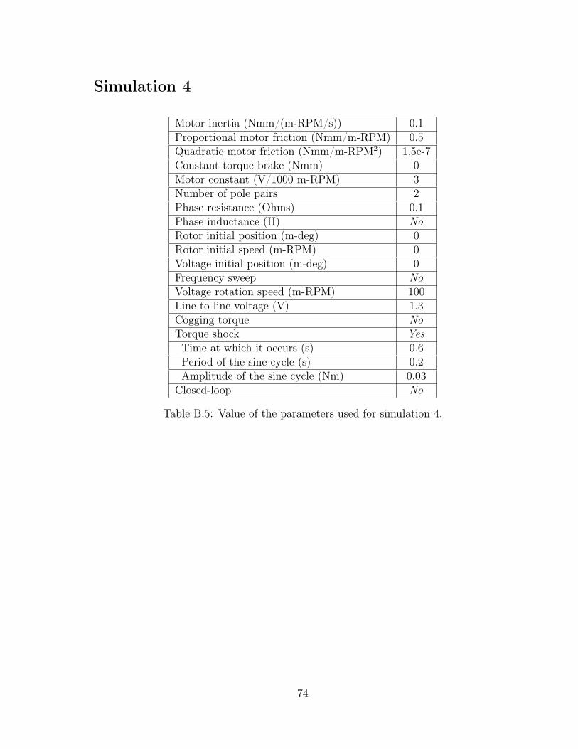
Simulation 4
Motor inertia (Nmm/(m-RPM/s)) 0.1Proportional motor friction (Nmm/m-RPM) 0.5Quadratic motor friction (Nmm/m-RPM2) 1.5e-7Constant torque brake (Nmm) 0Motor constant (V/1000 m-RPM) 3Number of pole pairs 2Phase resistance (Ohms) 0.1Phase inductance (H) NoRotor initial position (m-deg) 0Rotor initial speed (m-RPM) 0Voltage initial position (m-deg) 0Frequency sweep NoVoltage rotation speed (m-RPM) 100Line-to-line voltage (V) 1.3Cogging torque NoTorque shock YesTime at which it occurs (s) 0.6Period of the sine cycle (s) 0.2Amplitude of the sine cycle (Nm) 0.03
Closed-loop No
Table B.5: Value of the parameters used for simulation 4.
74

Bibliography
[1] S. Baldursson. “BLDC Motor Modelling and Control - A Matlab®/Simulink®
Implementation”. MA thesis. Chalmers Tekniska Högskola, 2005.
[2] Viktor Bobek. PMSM Electrical Parameters Measurement. 2013.
[3] Tech Briefs. Reasons for Turning to Slotless DC Motor Technology. 2015. url:http://www.techbriefs.com/component/content/article/22932.
[4] W. Brown. “Brushless DC Motor Control Made Easy”. In: Microchip TechnologyInc. (2002).
[5] J. C. Gamazo-Real, E. Vazquez-Sanchez, and J. Gomez-Gil. “Position and SpeedControl of Brushless DC Motors Using Sensorless Techniques and ApplicationTrends”. In: sensors (2010), pp. 6901–6947.
[6] A. Hartman and W. Lorimer. Cogging torque control in brushless DC motors.2000.
[7] S. Lee, T. Lemley, and G. Keohane. A comparison study of the commutationmethods for the three-phase permanent magnet brushless DC motor.
[8] Melexis. About us. url: https://www.melexis.com/en/about-us (visited on05/11/2017).
[9] Melexis. Annual Report 2016. Mar. 2017.
[10] Melexis. Investors - Corporate Governance. url: https://www.melexis.com/en / investors / corporate - governance / board - of - directors (visited on05/11/2017).
[11] Melexis. News - Melexis Q1 2017 results. url: https://www.melexis.com/en/news/2017/financial/melexis-q1-2017-results (visited on 05/11/2017).
[12] Microsemi. “Park, Inverse Park and Clarke, Inverse Clarke Transformations MSSSoftware Implementations User Guide”. In: (), p. 5.
75
[13] B. Tibor, V. Fedak, and F. Durovsky. “Modeling and Simulation of the BLDCMotor in MATLAB GUI”. In: IEEE (2011), pp. 1403–1407.
[14] Wikipedia. PID controller. 2017. url: https://en.wikipedia.org/wiki/PID_controller.
[15] digitalPimple Youtube. Brushless DC Motors & Control - How it Works. 2012.url: https://www.youtube.com/watch?v=ZAY5JInyHXY.
[16] Z. Q. Zhu and D. Howe. “Influence of Design Parameters on Cogging Torque inPermanent Magnet Machines”. In: IEEE Transactions on Energy Conversion 15.4(Dec. 2000), pp. 407–412.
76
Related Documents