Academic Year 2004/2005 Warsaw University of Technology Faculty of Electronics and Information Technology Electrical and Computer Engineering Master of Science Thesis Name of Student: Robert Jastrzębski, B.Sc. Title of Thesis: Steganography as an aspect of secure data maintenance Supervisor Rajmund KoŜuszek, M.Sc. Evaluation: ……………………. ………………………………… Signature of the Head of Examination Committee

Welcome message from author
This document is posted to help you gain knowledge. Please leave a comment to let me know what you think about it! Share it to your friends and learn new things together.
Transcript
Academic Year 2004/2005
Warsaw University of Technology
Faculty of Electronics and Information Technology
Electrical and Computer Engineering
Master of Science
Thesis
Name of Student: Robert Jastrzębski, B.Sc.
Title of Thesis: Steganography as an aspect of secure data maintenance
Supervisor
Rajmund KoŜuszek, M.Sc.
Evaluation: …………………….
…………………………………
Signature of the Head
of Examination Committee
Electrical and Computer Engineering
Name: Robert Jastrzębski
Date of Birth: September 29, 1980
Starting date of Studies: October 1, 2003
Curriculum Vitae:
I was born on September 29, 1980 in Warsaw, Poland. I attended XXVIII LO under the
patronage of Jan Kochanowski in Warsaw. In October 1999 I started my studies at Warsaw
University of Technology. In October 2003 I graduated with a Bachelor’s degree. My
Bachelor Thesis concerned application of digital signature to electronic forms. Starting from
October 2003 I continue my studies at Warsaw University of Technology, at the Faculty of
Electronics and Information Technology with specialization Computer Systems and Networks.
I am an owner of a Certificate in Advanced English (CAE) and Zentrale Mittelstufenprüfung
(ZMP) German certificate. My interests are chess and bridge.
…………………………
Signature of the Student
M.Sc. Examination
Examination was held on ………………………………………………………………………
With the result: ………………………………………………………………………………….
Final Result of the Studies: ……………………………………………………………………..
Suggestions and Remarks of the M.Sc. Examination Committee ……………………………..
…………………………………………………………………………………………………...
…………………………………………………………………………………………………...
- 3 -
SUMMARY
The thesis presents methods, which can be applied to ensure secure data maintenance under
Microsoft Windows operating system. The described concept bases on steganography, which
is a technique of hiding information inside other data, such as for instance, structure of
image files. The idea is to increase security of such hidden information, by combining the
watermarking process together with data encryption.
A detailed analysis of most popular graphics file formats was essential from the point of view
of the Theis, to check and verify all possible ways of achieving the intended goal. Apart from
graphical analysis, a research on data encryption algorithms has also been performed, in
order to choose the most suitable algorithm for project’s purposes.
The obtained results show, that application of various methods results in wide choice of
possibilities, of making the most of such approach to maintaining data security. Moreover,
this idea has numerous expansion possibilities, and may be used with great intensity in our
expanding computer environment.
Keywords: steganography, watermark, data security, data encryption, graphics file formats
- 4 -
TABLE OF CONTENTS
I. INTRODUCTION ........................................... 6
1.1 Idea of data security .......................................................................................... 6
1.2 Aim of the Thesis ............................................................................................... 7
II. PRELIMINARY SPECIFICATION.......... 9
2.1 Project assumptions and constraints ................................................................ 9
2.2 Functional requirements ..................................................................................10 2.2.1 Software requirements .................................................................................10
2.2.2 Hardware requirements ................................................................................11
2.2.3 Image standards ...........................................................................................11
2.2.4 Image consistency........................................................................................12
2.2.5 Encryption standards....................................................................................12
III. ANALYSIS .................................................. 14
3.1 Popular image file formats ...............................................................................14 3.1.1 BMP (OS/2 Bitmap) ....................................................................................14
3.1.2a GIF (version 87a).......................................................................................17
3.1.2b GIF (version 89a).......................................................................................21
3.1.3 JPEG ...........................................................................................................24
3.2 Data encryption algorithms..............................................................................26 3.2.1 Block ciphers ...............................................................................................27
3.2.2 Stream ciphers .............................................................................................28
3.2.2.1 RC4 stream cipher.................................................................................29
3.2.3 Cryptographic services under MS Windows.................................................31
3.3 Methods of applying steganography ................................................................33 3.3.1 Noise method...............................................................................................33
3.3.2 Block methods .............................................................................................34
IV. PROJECT DESCRIPTION.................... 36
4.1 Implementation choices ....................................................................................36 4.1.1 Programming platform.................................................................................36
4.1.2 Application type ..........................................................................................36
4.1.3 Application simplicity vs. high functionality................................................36
4.1.4 Installation...................................................................................................37
- 5 -
4.2 The main process ..............................................................................................39 4.2.1 Attaching information to an image ...............................................................39
4.2.2 Extracting information from an image..........................................................45
4.3 Application features..........................................................................................48 4.3.1 Stick to the standards ...................................................................................48
4.3.2 Image preview .............................................................................................52
4.3.3 Method simulation .......................................................................................53
V. RESEARCH................................................. 56
5.1 Method comparison..........................................................................................56
5.2 Processing speed ...............................................................................................57
VI. SUMMARY ................................................. 59
6.1 Summary of the work.......................................................................................59
6.2 Possible expansion chances ..............................................................................60 6.2.1 Other graphics file formats...........................................................................60
6.2.2 Other file formats.........................................................................................61
REFERENCES................................................. 63
- 6 -
I. Introduction
1.1 Idea of data security
If someone asked you why we need data security, would you find a brief answer for
such stated question? Rather not. Concept of data security is very wide in today’s
computerized society. Various aspects of every day’s life depend on how well certain
portions of data are secured. We are not only talking about issues connected with
computers, however the concept of data security is used most widely as it comes to
dealing with information, which is being kept or exchanged using computers and
internet. Information is always secured for a certain purpose, such as for example:
� hiding contents of some data (privacy), which is being realized by the means
of data encryption algorithms
� exchanging data between two parties is performed by the means of public key
encryption of data
� data verification, which is also a subject to public key infrastructure
� authentication and authorization concepts
� secure protocol encryption such as SSL, which is used in general to establish
secure connection between a server and a client
� prevention from all sorts of internet attacks
� network security
� and a wide range of other concepts, which will not be mentioned here, as there
would be simply too many of them to cover
The concept, which will be applied as far as the thesis is concerned, will be dedicated
to data privacy. The question arises, how to keep data on a computer, such that it
would be secured and on the other hand such secured data will be hardly recognizable
by a potential intruder? The following chapter named Aim of the Thesis should
disperse all uncertainties.
Steganography ... Introduction
- 7 -
1.2 Aim of the Thesis
There are many ways of securing information against an attack. One of the most
secure and commonly used approaches is data encryption. Various encrypting
algorithms have been developed over the years, but all of them share similar problems
as it comes to obtaining expected security. Their consistence is endangered by various
kinds of attacks, many of which are designed especially for particular algorithms.
Security of data encryption is usually bound by the length of key, which is being used
in the encryption and decryption processes. Of course the longer the key, the smaller
the chance of breaking the protection. However, generation and usage of such long
keys, results in many problems, such as high complexity of the algorithm, necessity of
large computational power, and time-consuming execution of the cryptographic
processes.
The question arises, if all of this is really necessary. The answer is quite simple. If the
information is kept in such way, that it is obvious for a skilled hacker to determine,
what kind of algorithm to encrypt the data had been used, or what the length of the
plain text message or the key is, than it is indeed necessary to preserve maximum
security. On the other side, if it was practically impossible to determine if some data
contains encrypted information, than it would be enough to take some reasonable
precautions as it comes to cryptographic approach. There would be no need of using
extremely long keys and all of the necessary operations would be performed faster.
The idea is to include cryptographic information inside the structure of some file
format, thus in fact in the image itself. This process must be performed in such way,
that it would be impossible to notice at first glance that the file has been modified.
Graphical file formats come in handy in this situation. They offer many interesting
possibilities, as modification of their file structure is concerned. The interference with
such files should be done in such a way, that while comparing the original image with
the modified one, no visual difference should be observed by the human’s eye.
The process of attaching information to image or sound file formats is called
steganography, while the information itself is denoted as a watermark. So, the idea is
to combine both of the above-mentioned techniques. The intention is to first encrypt
Steganography ... Introduction
- 8 -
the information, and than distribute it inside an image file in some clever way, as to
leave no trace for a potential attacker. Such information will be afterwards protected
in two ways, first by a cryptographic algorithm, second by steganography. It is worth
mentioning that standard steganographic approaches apply to data, which is not
encrypted in any way, thus the approach used in the project is twice as secure.
A detailed analysis of the most popular graphical file formats is essential, to
determine all possible ways of applying the idea of steganography to each of them.
- 9 -
II. Preliminary specification
2.1 Project assumptions and constraints
There are two important aspects of the work one has to explain, before further steps
may be accomplished. The first one concerns image modification, the second one is
connected to cipher algorithms. Since the image files are a subject to file
modification, it must be clearly determined if such modifications undergo any
copyright constraints. The same applies to functions and algorithms used in the
encryption and decryption of data. It must be clearly explained if such functions may
be used or modified without any bounds.
In general, graphics file formats are not subject to copyrights, because for a product to
be copyrighted, it must fulfill two conditions: it must be work of authorship, and must
be fixed in a tangible medium of expression. Only documentation on specific file
formats is a subject of copyrights, as it often states, that the name of a company,
which developed this format, should be mentioned. For example, the GIF (Graphics
Interchange Format) is a registered trademark. Copyrights of this file format belong to
the CompuServe Company and documentation of GIF files has been given away
freely. One of the terms of the license states, that if a GIF file format is used by some
commercial software, it must be stated that this format is under license of
CompuServe.
Apart from the file structure itself, there may be some other constraints as it comes to
image modification. Namely, some algorithms, which are being used to compress data
within graphics file formats, undergo copyrights. As an example of such situation, an
algorithm called Lempel-Ziv-Welch (LZW) can be mentioned. Raster data used in
GIF files is compressed using this algorithm. Its copyrights are held by Unisys
Corporation, thus it must not be modified in any way.
The same applies to cryptographic functions, which may be used for commercial
purposes. It must be clearly stated which algorithm is used, and who holds its
copyrights.
Steganography ... Preliminary specification
- 10 -
2.2 Functional requirements
2.2.1 Software requirements
The application is being built under Visual Basic, which is part of Microsoft Visual
Studio. Nature of the program needs to be of visual type, because the user has to have
opportunity to observe how the image is being changed and if such change is
acceptable from the user’s point of view. These aspects make the potential application
run under Microsoft Windows Operating Systems. Such systems are most commonly
used visual operating systems in the world. The program is created under MS Visual
Basic. It is obvious that the result of its compilation will be an executable file, which
should be able run under different versions of MS Windows OS, such as Windows 98,
NT, XP.
It is possible to create an installation package of the program, which will contain all
necessary libraries needed to run it. Another option is to create some script to register
all necessary libraries needed to run the program, and keep the application as a
standalone version, without having to create any installation package and thus making
probably more interference to the system, having to install some unnecessary libraries
or to modify system’s registry file. The second option seems to be a better choice,
since size of the executable file will be rather small and there will not be many other
file dependencies (i.e. with libraries). Portability of the application is an interesting
aspect as well, since it will probably be possible to transport the program using even a
floppy disk, thus allowing the user to transport it quickly from one software platform
to another, without having to make much effort in installing and running the program.
Finally, an important assumption needs to be mentioned. Namely, potential methods
of implementation are not a subject to any particular operating system (or in other
words software requirements). The overall idea is to propose some concepts and test
them by the means of an application, which would run under Microsoft Windows
operating system. The same applies of course to hardware requirements.
Steganography ... Preliminary specification
- 11 -
2.2.2 Hardware requirements
Apart from the above mentioned software requirements, one has to think about the
hardware aspect as well. The problem concerns speed of the methods applied during
the attachment and extraction of information. This problem is quite important and
must not be neglected. Speed of the calculations will depend on certain factors, which
include: processor strength, size of RAM, size of file which is being modified, length
of the attached message, speed of the encryption algorithm and complication of the
applied method. This leads to a conclusion, that the code of the program should be
implemented very cautiously, to ensure that the above factors would not influence
calculation speed too drastically.
Of course there are certain things, which we cannot control. The better the processor
and the more operational memory, the quicker the calculations will follow. The
processor however, will be the most important factor of the platform. Other issues,
such as described size of file or message length are rather a subject to method
implementation, than to hardware requirements, however they were mentioned to
present an overall idea, what the speed of the calculations will depend on.
2.2.3 Image standards
The main goal of the project is to attach information to an image file format. The
choice what image file formats are suitable for the project was really simple. Two
factors have been taken into consideration. The images must be of very popular and
commonly used type and secondly this type should not be restricted by too many
factors. Such aspects have been already mentioned in the preliminary specification
part of the thesis.
In general, three of the most popular image formats have been chosen for further
implementation. These include: Windows OS/2 Bitmap (or shortly BMP), Graphics
Interchange Format (GIF) and Joint Photographic Experts Group (JPG or JPEG).
These formats are used in most of the aspects of image maintenance on the Internet
but for individual purposes on personal computers as well. Methods of
implementation have to ensure, that after attaching the information to such files, they
stick to their own standards, which means that other application responsible for
Steganography ... Preliminary specification
- 12 -
operating on such file types have to be able to open them and treat their structure
contents properly.
So, a detailed file structure analysis needs to be performed. Apart from it, it was
assumed that no one’s own file formats are introduced, only predefined and
commonly known file types are used in the project.
2.2.4 Image consistency
An aspect of visuality of the image is understood by the above term. Part of the main
goal of the project is not only to be able to attach encrypted information to the image
and then to extract it from the image in order to decrypt it afterwards. An important
condition should also be fulfilled. Namely, the modified image should not differ
visually from the initial picture. This function however, cannot be realized by any
means of the implementation phase. The user must be able to decide and accept the
obtained results or not.
In other words, the application should present the initial and modified images in such
way, that it would be possible for the user to compare both of the pictures in order to
make the decision if he wishes to save the modified image or not. A nice idea would
be also to prepare some simulation mechanism, which would operate on the initial
image file taking on input some condition the user wishes to meet and displaying a
modified image afterwards. Such process should be of course quicker than the original
attachment phase, to make it more convenient for the user to use such tool.
2.2.5 Encryption standards
An important aspect of project’s implementation is the choice of suitable encryption
algorithms. There are several important standards, that such an algorithm should
fulfill, to qualify for further steps of the implementation. One of the most important
factors is of course its security standard. This without any doubts depends on key
length used during the encryption. The longer the key, the more secure the encoding
will be. On the other hand, the longer the key, the more time it takes to perform the
encryption.
Steganography ... Preliminary specification
- 13 -
Another aspect related to key length is how the key will be stored. It is considered,
that the key will be stored inside the image itself, which in case of very small size of
an image may be hard to perform, and thus preserve high standard of encryption
security. So the conclusion is as following: the algorithm should be fast, but there
should not be a big significance between keys, which are longer or shorter. Of course
such issue will always exist, but the choice must take such aspect into consideration as
well. In general, one must choose between two groups of encryption algorithms,
which are symmetric and asymmetric ciphers. Results and conclusions will be
presented in the analysis section of the thesis.
- 14 -
III. Analysis
3.1 Popular image file formats
3.1.1 BMP (OS/2 Bitmap)
As some may incorrectly believe, the term “bitmap” does not apply only to .BMP
files. A bitmap is an image which is stored and which can be displayed as a set of
pixels. A .BMP file extension applies to Windows DIB files. All of this may look
little confusing, but the easiest way of defining what a .BMP file is, is as following.
Windows bitmap files are being stored in a DIB (device-independent bitmap) format.
It means that such bitmaps may be displayed on any kind of a display device. The
default filename extension of a DIB file is .BMP, however .DIB files can be
encountered as well.
A bitmap image file consists of four major parts: bitmap-file header, bitmap-
information header, color table, and array of bytes, which represents bits of the
bitmap. The structure of an OS/2 Bitmap for version 1.x is represented as follows:
BITMAPFILEHEADER bmfh;
BITMAPINFOHEADER bmih;
RGBQUAD aColors[];
BYTE aBitmapBits[];
The bitmap-file header covers information on type, size, and layout of the file. The
bitmap-information header contains information about image size, type of
compression used (if any) and color format of the image. The color table is an array of
length equal to the number of colors used in the bitmap. This applies only to bitmaps
of bit-depth equal to 1, 4, and 8, and does not occur in 24-bit bitmaps, since in 24-bit
files each pixel is represented by RGB values. The colors in a color table should
appear in their importance order, because it may happen, that on some machines it is
impossible to represent a particular bitmap using the available color palette. The array
of bytes follows the color table. Pixel values are represented horizontally (as rows),
starting from left to right, and from bottom to top (!). The first byte of the array is in
Steganography ... Analysis
- 15 -
fact the bottom-left-hand corner of the image, and the last byte represents the top-
right-hand corner.
A few words must be introduced as bit count (bit depth) of a bitmap is considered. It
may be equal to 1,4,8 or 24. When we consider the simplest monochrome 1-bit
bitmap, it is obvious that we may deal here with only 2 colours. These colours are
defined in the color table, and if a data bit is set to 0, first entry in the color table is
being taken, and similarly when it equals 1, the second entry is being considered.
Thus a conclusion can be made, that the simplest way to reverse colors in a 1-bit
bitmap is to interchange the two entries of the color table, without making any
interference with the data bytes. Similar approach may be used for 4 and 8 bit images,
however not for 24-bit files. These bitmaps do not contain any color table to which
their pixels could refer. The bitmap array is simply represented by a set of “triplets”,
which represent RGB values of a pixel. Each color can have values from 0 to 255,
which is in fact representation of 8 bits (28 = 256), and since we have red, green and
blue bytes, it makes in total of 24 bits.
Bitmap compression is an aspect, which may turn out crucial for the project, as it may
allow possible interference with the file structure. It is worth mentioning, that only 4
and 8 bit bitmaps may undergo compression. Compression used in bitmap
compressing is lossless, which means that after the decompression process, we obtain
the initial file without any changes made to it (equivalent quality). In other file
formats, such as jpeg for instance, we cannot obtain the initial image after its
compression. The compression used in bitmap encoding is so called Group Encoding
or Run-Length Encoding (RLE). It uses two modes: Encoded Mode and Absolute
Mode. The compression slightly differs for 4- and 8-bpp bitmaps.
It is somewhat easier to explain at first how compression of an 8-bpp bitmap is
interpreted, since the whole byte is used throughout the process, not taking into
consideration 4-bit blocks. In Encoded Mode a block of information consisting of two
bytes is being considered. The first value holds the number of repetitions of the
second byte, which holds color index of a pixel (reference to the color table). So, to
present a small example, we may write down the following:
Steganography ... Analysis
- 16 -
05 2E is in fact 2E 2E 2E 2E 2E, and 06 05 is 05 05 05 05 05 05
The first byte may be set to 0, to indicate a special condition, which takes place. It is
interpreted as follows:
00 00 is end of line
00 01 is end of file
00 02 is delta
The delta may occur the most important factor as the project’s goal is concerned. Two
bytes that follow delta (00 02) indicate the position of the next pixel, relative to the
current position. So, having the following example:
00 02 03 01
it means, that the position of the next pixel is three positions right and one position
down relative from the current pointer position in the data array. Second mode used
during compression is Absolute Mode. It allows indicating a number of bytes, which
are treated as single pixels. In other words, instead of such notation:
01 05 01 1A 01 53 01 A4 01 11 01 6B
we may use the following:
00 06 05 1A 53 A4 11 6B 00
which is obviously shorter, especially for long “single pixel” sequences. As it may be
noticed, the Absolute Mode is indicated, when a sequence of bytes starts with 00 and
follows by values from 03 to FF. Values from 00 to 02 are reserved for special escape
characters in the Encoded Mode.
The difference in 4-bpp image compression is that in the Encoded Mode the second
byte of data is in fact treated as two 4-bit blocks. These blocks are called nibbles, and
so, a high-order nibble represents low-order bits of a byte. Similarly, a low-order
nibble represents high-order bits of a byte. What follows, is that the second byte
Steganography ... Analysis
- 17 -
(reference to the color table) holds two values instead of one, as in the 8-bpp
compressed bitmap. The pixels are being drawn alternately, starting from the high-
order nibble. An example below demonstrates how it is being done:
05 13 is in fact 1 3 1 3 1, and 06 A0 is A 0 A 0 A 0
The end of line (00 00), end of file (00 01) and delta (00 02) behave identically as in
the 8-bpp compression. The Absolute Mode is almost identical to the previous one;
the difference is that the nibbles are picked, instead of whole bytes:
00 06 1A 34 04 00 is 1 A 3 4 0 4
Conclusions:
It seems that the .BMP files are suitable for the project and will allow some additional
data to be put inside their file structure, without spoiling “visuality” of the image.
However, there are some constraints, namely, only 4 and 8 bits-per-pixel compressed
bitmaps may be used. It comes as a result of a property of the compressed data,
namely the so-called “delta”. It allows jumping from a current pointer position to
another location in the data array, while parsing the image. This property allows
putting additional data (as an encrypted information for example) in the space, which
is present between the two jump points.
3.1.2a GIF (version 87a)
Graphics Interchange Format (or shortly GIF) has been designed in 1987 by
CompuServe Inc. It combines high quality together with portability of an image. The
structure of a GIF87a file consists in general of the following:
� GIF Signature
� Screen Descriptor
� Global Color Map
� Image Descriptor
� Local Color Map
� Raster Data
Steganography ... Analysis
- 18 -
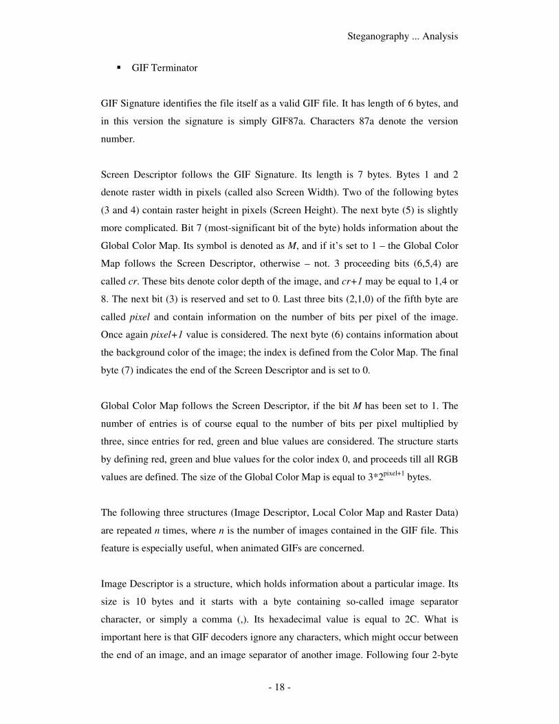
� GIF Terminator
GIF Signature identifies the file itself as a valid GIF file. It has length of 6 bytes, and
in this version the signature is simply GIF87a. Characters 87a denote the version
number.
Screen Descriptor follows the GIF Signature. Its length is 7 bytes. Bytes 1 and 2
denote raster width in pixels (called also Screen Width). Two of the following bytes
(3 and 4) contain raster height in pixels (Screen Height). The next byte (5) is slightly
more complicated. Bit 7 (most-significant bit of the byte) holds information about the
Global Color Map. Its symbol is denoted as M, and if it’s set to 1 – the Global Color
Map follows the Screen Descriptor, otherwise – not. 3 proceeding bits (6,5,4) are
called cr. These bits denote color depth of the image, and cr+1 may be equal to 1,4 or
8. The next bit (3) is reserved and set to 0. Last three bits (2,1,0) of the fifth byte are
called pixel and contain information on the number of bits per pixel of the image.
Once again pixel+1 value is considered. The next byte (6) contains information about
the background color of the image; the index is defined from the Color Map. The final
byte (7) indicates the end of the Screen Descriptor and is set to 0.
Global Color Map follows the Screen Descriptor, if the bit M has been set to 1. The
number of entries is of course equal to the number of bits per pixel multiplied by
three, since entries for red, green and blue values are considered. The structure starts
by defining red, green and blue values for the color index 0, and proceeds till all RGB
values are defined. The size of the Global Color Map is equal to 3*2pixel+1
bytes.
The following three structures (Image Descriptor, Local Color Map and Raster Data)
are repeated n times, where n is the number of images contained in the GIF file. This
feature is especially useful, when animated GIFs are concerned.
Image Descriptor is a structure, which holds information about a particular image. Its
size is 10 bytes and it starts with a byte containing so-called image separator
character, or simply a comma (,). Its hexadecimal value is equal to 2C. What is
important here is that GIF decoders ignore any characters, which might occur between
the end of an image, and an image separator of another image. Following four 2-byte
Steganography ... Analysis
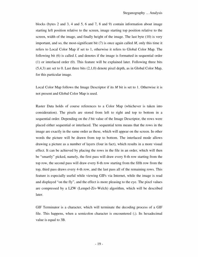
- 19 -
blocks (bytes 2 and 3, 4 and 5, 6 and 7, 8 and 9) contain information about image
starting left position relative to the screen, image starting top position relative to the
screen, width of the image, and finally height of the image. The last byte (10) is very
important, and so, the most-significant bit (7) is once again called M, only this time it
refers to Local Color Map if set to 1, otherwise it refers to Global Color Map. The
following bit (6) is called I, and denotes if the image is formatted in sequential order
(1) or interlaced order (0). This feature will be explained later. Following three bits
(5,4,3) are set to 0. Last three bits (2,1,0) denote pixel depth, as in Global Color Map,
for this particular image.
Local Color Map follows the Image Descriptor if its M bit is set to 1. Otherwise it is
not present and Global Color Map is used.
Raster Data holds of course references to a Color Map (whichever is taken into
consideration). The pixels are stored from left to right and top to bottom in a
sequential order. Depending on the I bit value of the Image Descriptor, the rows were
placed either sequential or interlaced. The sequential term means that the rows in the
image are exactly in the same order as these, which will appear on the screen. In other
words the picture will be drawn from top to bottom. The interlaced mode allows
drawing a picture as a number of layers (four in fact), which results in a more visual
effect. It can be achieved by placing the rows in the file in an order, which will then
be “smartly” picked, namely, the first pass will draw every 8-th row starting from the
top row, the second pass will draw every 8-th row starting from the fifth row from the
top, third pass draws every 4-th row, and the last pass all of the remaining rows. This
feature is especially useful while viewing GIFs via Internet, while the image is read
and displayed “on the fly”, and the effect is more pleasing to the eye. The pixel values
are compressed by a LZW (Lempel-Ziv-Welch) algorithm, which will be described
later.
GIF Terminator is a character, which will terminate the decoding process of a GIF
file. This happens, when a semicolon character is encountered (;). Its hexadecimal
value is equal to 3B.
Steganography ... Analysis
- 20 -
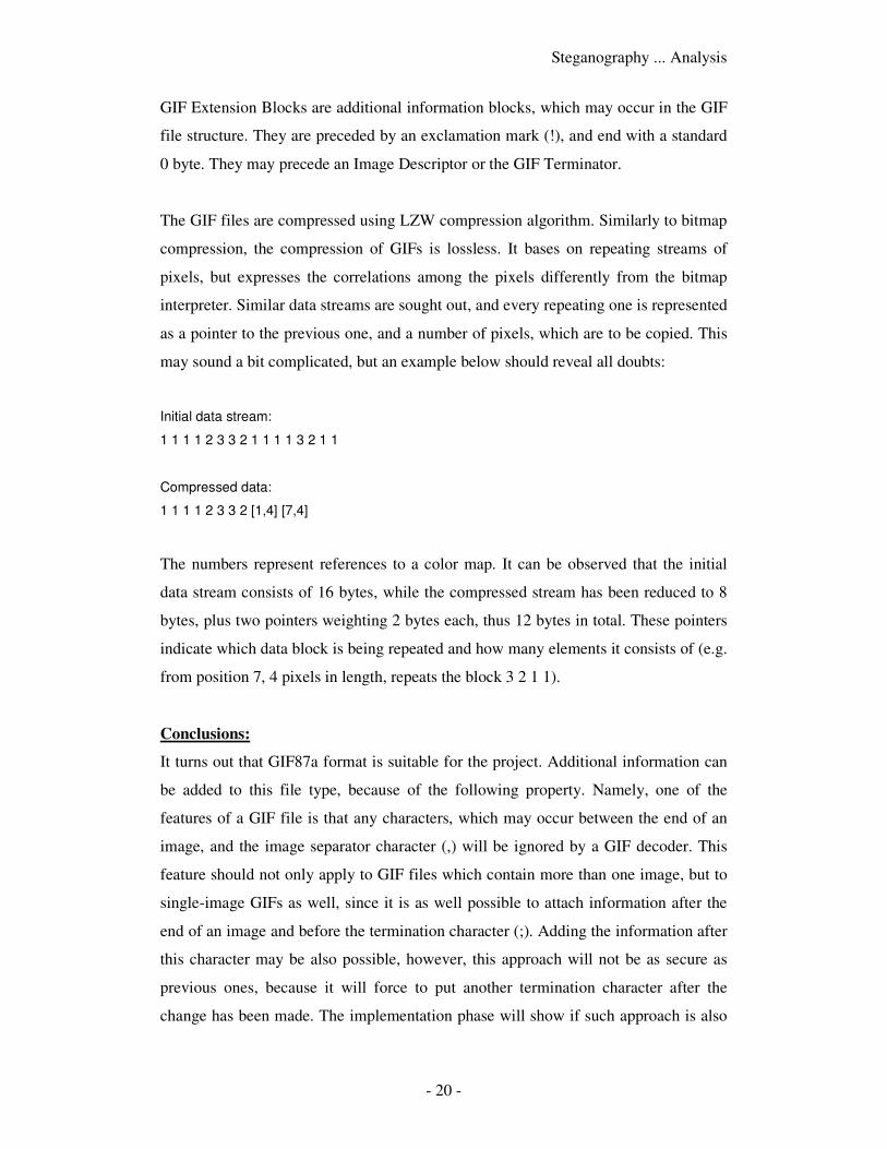
GIF Extension Blocks are additional information blocks, which may occur in the GIF
file structure. They are preceded by an exclamation mark (!), and end with a standard
0 byte. They may precede an Image Descriptor or the GIF Terminator.
The GIF files are compressed using LZW compression algorithm. Similarly to bitmap
compression, the compression of GIFs is lossless. It bases on repeating streams of
pixels, but expresses the correlations among the pixels differently from the bitmap
interpreter. Similar data streams are sought out, and every repeating one is represented
as a pointer to the previous one, and a number of pixels, which are to be copied. This
may sound a bit complicated, but an example below should reveal all doubts:
Initial data stream:
1 1 1 1 2 3 3 2 1 1 1 1 3 2 1 1
Compressed data:
1 1 1 1 2 3 3 2 [1,4] [7,4]
The numbers represent references to a color map. It can be observed that the initial
data stream consists of 16 bytes, while the compressed stream has been reduced to 8
bytes, plus two pointers weighting 2 bytes each, thus 12 bytes in total. These pointers
indicate which data block is being repeated and how many elements it consists of (e.g.
from position 7, 4 pixels in length, repeats the block 3 2 1 1).
Conclusions:
It turns out that GIF87a format is suitable for the project. Additional information can
be added to this file type, because of the following property. Namely, one of the
features of a GIF file is that any characters, which may occur between the end of an
image, and the image separator character (,) will be ignored by a GIF decoder. This
feature should not only apply to GIF files which contain more than one image, but to
single-image GIFs as well, since it is as well possible to attach information after the
end of an image and before the termination character (;). Adding the information after
this character may be also possible, however, this approach will not be as secure as
previous ones, because it will force to put another termination character after the
change has been made. The implementation phase will show if such approach is also
Steganography ... Analysis
- 21 -
possible, since we do not know how different GIF interpreters will treat such
modification to GIF files, especially if it is possible to modify the image using such an
editor.
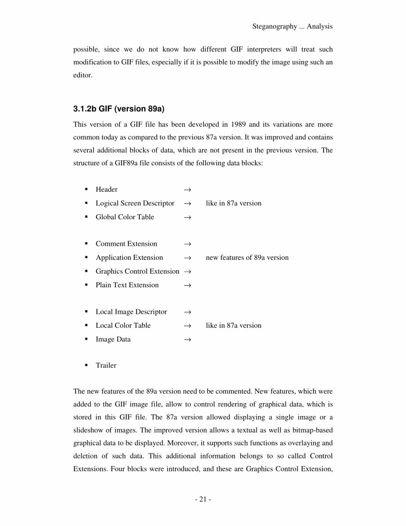
3.1.2b GIF (version 89a)
This version of a GIF file has been developed in 1989 and its variations are more
common today as compared to the previous 87a version. It was improved and contains
several additional blocks of data, which are not present in the previous version. The
structure of a GIF89a file consists of the following data blocks:
� Header →
� Logical Screen Descriptor → like in 87a version
� Global Color Table →
� Comment Extension →
� Application Extension → new features of 89a version
� Graphics Control Extension →
� Plain Text Extension →
� Local Image Descriptor →
� Local Color Table → like in 87a version
� Image Data →
� Trailer
The new features of the 89a version need to be commented. New features, which were
added to the GIF image file, allow to control rendering of graphical data, which is
stored in this GIF file. The 87a version allowed displaying a single image or a
slideshow of images. The improved version allows a textual as well as bitmap-based
graphical data to be displayed. Moreover, it supports such functions as overlaying and
deletion of such data. This additional information belongs to so called Control
Extensions. Four blocks were introduced, and these are Graphics Control Extension,
Steganography ... Analysis
- 22 -
Plain Text Extension, Application Extension and Comment Extension. Control
Extensions may occur anywhere in the file, following the Global Color Table. They
begin with the Extension Introducer, a byte of value 0x21.
Graphics Color Extension is responsible for controlling the way the bitmap is being
displayed. This includes if the graphic is displayed in transparent or in opaque way, if
this graphic is to be restored or deleted, and if user input is required for further
continuation. The block starts with byte value 0xF9. It is being followed by BlockSize
with value 0x04, which is constant and determines the size of remaining fields, which
are: Packed, DelayTime, ColorIndex and Terminator. The Packed byte consists of the
following: starting from the most significant bits; bits 7-5 are Reserved, bits 4-2
specify the Disposal Method (how it is to be interpreted, after the graphic has been
displayed – if to overwrite it or not), bit 1 is the User Input Flag (if 1 – user action
such as key press or mouse click is required to continue displaying the image,
otherwise 0 – no action required to continue), bit 0 is called Transparent Color Flag,
and if is set to 1, the ColorIndex will contain a color transparency index, otherwise it
will be set to 0. The DelayTime block (of length word) specifies the delay in
hundredths of a second between continuous displayments. The ColorIndex contains a
value only if the Transparent Color Flag bit is set to 1. The Terminate byte of value
0x00 ends the Graphics Color Extension block.
Plain Text Extension allows mixing plain text ASCII with a bitmap image. This
extension is especially useful when it comes to displaying a readable text, which may
be included in the GIF file. Such text can be overlaid onto an image itself. The block
starts with byte of value 0x01 and follows with BlockSize with constant value of
0x0C. The following data contains information about the text itself, its position,
specific data about how to display particular characters in the grid of pixels, and
foreground and background color of the text. The block ends as usual with a block
terminator of value 0.
Application Extension allows storing such data, which is to be understood only by
software applications, displaying GIF image files. Such information may turn out
vital, when it comes to display the image. The block is 14 bytes long, and starts with
Label byte 0xFF. Then follows the BlockSize byte (always 0x0B). The following data
Steganography ... Analysis
- 23 -
contains information specific for a particular information, such as Application
Identifier, Application Authentication Code, and pointer to Application Data sub-
blocks. The block ends with a standard Terminator.
Comment Extension holds comments, which are “human-readable”, and are stored in
a similar way as for example comments in C language. Each one of the comments
may contain 255 ASCII characters, and may include ASCII control codes. The
number of comments in a GIF file is not limited. The label identifying this block has
value of 0xFE. Afterwards, the CommentData bytes follow. The comment ends if the
Terminator byte is encountered.
Conclusions:
As in the following case (GIF file version 87a), the GIF89a image may be applied into
the project. What may turn out to be an advantage, as in comparison to the previous
case, is the possible occurrence of extended information contained in Extension
Blocks. For example, Comment Extension can surely be used for attaching additional
data to the file; however, such approach will not be that secure, because the comment
information contained in this Extension Block is human-readable. The Plain Text
Extension may be of greater benefit for the project, since not only plain information is
contained in such a block, but also it allows manipulating with this information using
several other controls. What might occur to be the greatest profit of using the
Extension Blocks, which support plain text/comments, is that using such notation,
appropriate bytes of data, included in actual raster data of an image, may be pointed
out, as to being part of an encoded message. In other words, plain text may be used to
point to bytes of image data, which will in fact be parts of the message, and will bind
the whole message together. In such approach it must be of course considered, that
some data bytes, which do not occur in image data, may be necessary for the proper
message binding, but in this case another approach should be used. Such “missing
bytes” would have to be encoded separately (possibly as parts of Plain Text Extension
or Comment Extension blocks), but this will be planned during the late phases of the
implementation part of the work.
Steganography ... Analysis
- 24 -
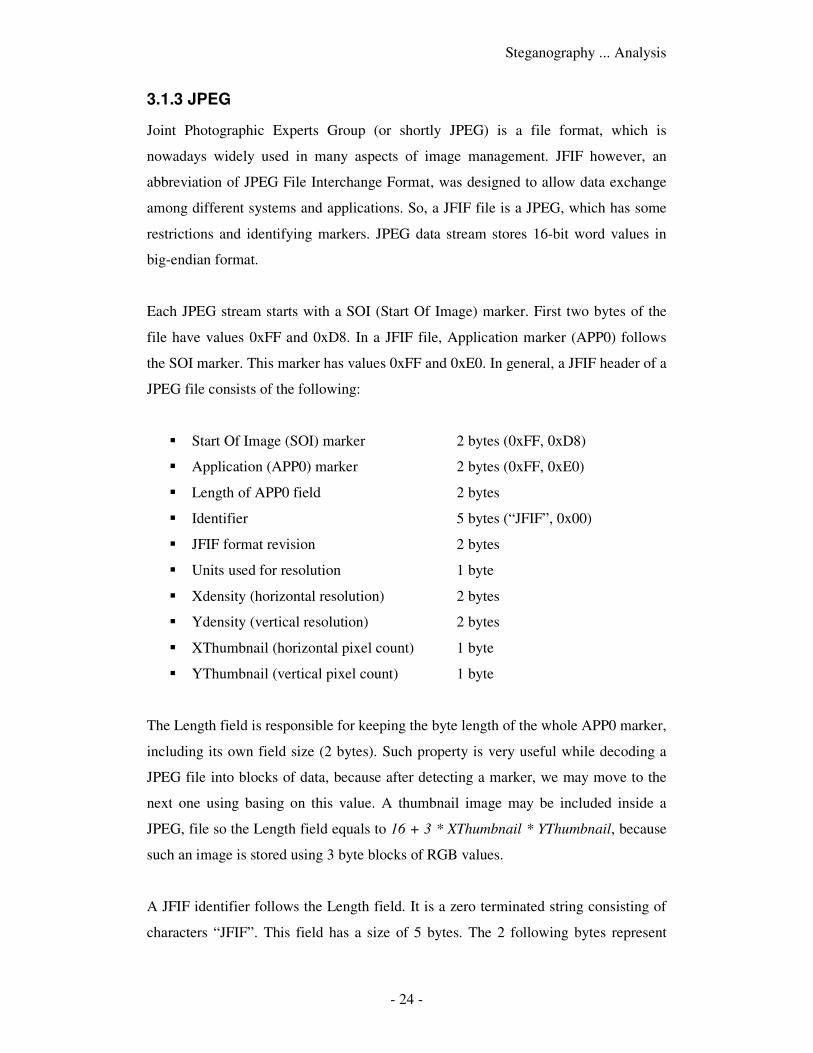
3.1.3 JPEG
Joint Photographic Experts Group (or shortly JPEG) is a file format, which is
nowadays widely used in many aspects of image management. JFIF however, an
abbreviation of JPEG File Interchange Format, was designed to allow data exchange
among different systems and applications. So, a JFIF file is a JPEG, which has some
restrictions and identifying markers. JPEG data stream stores 16-bit word values in
big-endian format.
Each JPEG stream starts with a SOI (Start Of Image) marker. First two bytes of the
file have values 0xFF and 0xD8. In a JFIF file, Application marker (APP0) follows
the SOI marker. This marker has values 0xFF and 0xE0. In general, a JFIF header of a
JPEG file consists of the following:
� Start Of Image (SOI) marker 2 bytes (0xFF, 0xD8)
� Application (APP0) marker 2 bytes (0xFF, 0xE0)
� Length of APP0 field 2 bytes
� Identifier 5 bytes (“JFIF”, 0x00)
� JFIF format revision 2 bytes
� Units used for resolution 1 byte
� Xdensity (horizontal resolution) 2 bytes
� Ydensity (vertical resolution) 2 bytes
� XThumbnail (horizontal pixel count) 1 byte
� YThumbnail (vertical pixel count) 1 byte
The Length field is responsible for keeping the byte length of the whole APP0 marker,
including its own field size (2 bytes). Such property is very useful while decoding a
JPEG file into blocks of data, because after detecting a marker, we may move to the
next one using basing on this value. A thumbnail image may be included inside a
JPEG, file so the Length field equals to 16 + 3 * XThumbnail * YThumbnail, because
such an image is stored using 3 byte blocks of RGB values.
A JFIF identifier follows the Length field. It is a zero terminated string consisting of
characters “JFIF”. This field has a size of 5 bytes. The 2 following bytes represent
Steganography ... Analysis
- 25 -
revision of the JFIF file. First byte contains major revision number, while second one
contains its minor one. Version, which is being used today is 1.02, previous revisions
were 1.00 and 1.01. These are the most important information contained in an APP0
Application marker.
Revision of a JFIF file is quite important, since optional JFIF extensions may follow
the APP0 marker, if the revision version is 1.02. So if we wish to add some extension
blocks to a JFIF file, we must remember to keep the revision number as 1.02,
otherwise some applications may not display the image correctly. A JFIF extension
consists of the following fields:
� Application (APP0) marker 2 bytes (0xFF, 0xE0)
� Length of APP0 field 2 bytes
� Identifier 5 bytes (“JFXX”, 0x00)
� Extension Code 1 byte
Three first fields are similar to these in the SOI marker. The last field however,
contains information about the data, which is being stored after this field. This filed
may have a various value, which will indicate purpose of this extension. It may
describe the following properties of a JPEG file: 0x10 - thumbnail encoded using
JPEG, 0x11 - thumbnail stored using 1-byte pixels and a palette, or 0x13 – thumbnail
stored using 3-byte RGB pixels.
Conclusions:
As it may be observed, a JPEG file may also come in handy as it comes to storing
information inside its file structure. However, the noise method is not advisable in this
case, since the image data is always compressed inside a JPEG. Of course, this does
not exclude implementing the noise method, since it looks like it would be enough to
decode the data, modify it and encode the modified data once again. This approach is
however not possible, because if we encode a JPEG and decode it afterwards, we
would not get the same result, meaning that file comparison of the initial and final file
would differ. It is a result of various processes a JPEG undergoes during the encoding
or decoding process. Such processes as quantization, cosine transforms always result
in creation of unwanted rubbish, which does not affect visuality of an image, but
Steganography ... Analysis
- 26 -
unfortunately affects its file content. Instead, various block methods may be applied,
starting from creation of one’s own marker blocks, or making the most of already
predefined file segments, such as a number of thumbnail images which may be
included inside a JPEG file.
3.2 Data encryption algorithms
It is assumed that the goal of the project is to create such application of message
encryption, that it would be secure enough to face against any possible hacker attack.
A detailed file-formats analysis shows, that in most cases it is practically impossible
for a third-party to notice that an image file has been modified and contains additional
information. Such information will be often divided into blocks of smaller size, to
ensure more secure allocation of such message parts inside a file, thus making it
harder, if not entirely impossible, for an attacker to work out the way it has been
stored, especially without use of a proper user-interface as well. However, the
message must not be of a totally plain type, meaning not encrypted at all. Such
approach would not be that secure and would allow an attacker to breach the file
structure easier, to get into possession of such information.
The task is to propose such encryption algorithm, which would match the above
conditions, and will not be bounded by to many constrains, such as for example:
maximal message length, key length, key generation problems and many more. The
idea is to implement some kind of a symmetric-key algorithm. The reasons for
choosing such type of algorithm are simple. Such algorithms require usage of only
one key, not a pair of keys like in nonsymmetric-key algorithms. Thus, the key
generation phase is much easier too. Moreover, their big advantage is the fact, that
they are much more faster than nonsymmetric-key algorithms. They also have their
drawbacks, such as for example having to store the key in a very secure manner.
When it comes to interchanging information between two parties, it may look as these
algorithms are much less secure, but an interesting assumption can be made.
At first, it must be considered, what is the purpose of attaching the message to an
image file. One of the reasons is simply to store hidden information for some private
purposes, not including any second-parties at this moment. This approach is the easier
Steganography ... Analysis
- 27 -
part. Another reason may be that we would like to interchange some information with
another party. This approach is more dangerous, since we would have to consider
having to transfer such a file, which could of course be intercepted by a third-party on
the way. And here we encounter a problem of key exchange.
One idea is that the key may be attached to the image file containing a message as
well. Of course, it would not be stored as plain text, but rather in some other smart
way, similar to message storing, and split throughout the file in some way. Another
idea is however being considered; namely, both parties will have a set of keys stored
somewhere on their disk space. These sets would be identical, and the encryption
process would only include choosing one of the keys from the database (lat us call it a
key-repository or shorter a repository), encrypting the message and attaching the
index of a key to the message. To decrypt the message, the second party would only
have to find a proper key in their repository according to the received index.
In fact, some calculations would probably have to be made, since symmetric-key
cryptography does not actually use the same cryptographic key for encryption and
decryption processes, but it is assumed that it is easy to compute the decryption key
knowing the encryption key (and the other way around). The symmetric-key
algorithms are divided in general into two groups: stream ciphers and block ciphers.
The first type encrypts the message bit after bit, and the second type deals with blocks
of bits, usually 64-bits long, but some of the ciphers use 128-bits blocks and others as
well. Since the way the algorithm deals with the message is important from the point
of view of the project, a detailed analysis of these two kinds of symmetric-key
algorithms has to be made.
3.2.1 Block ciphers
A block cipher in comparison to a stream cipher is an algorithm, which operates on
groups of bits of fixed length, which are called blocks. Size of a block is individually
determined by the algorithm being considered, however the most common block-size
is 64 bits and possibly 128 bits. It can be observed that certain functions are very
common to this kind of ciphers. These are: logical operations (XOR), S-Boxes and
permutations.
Steganography ... Analysis
- 28 -
What is an interesting aspect is the number of various attacks against block ciphers,
all of which base on certain properties of these ciphers. This includes: partial
differential cryptanalysis, slide attacks, boomerang attacks, integral attacks, algebraic
attacks, and many more. In general, a good block cipher must be tested against all of
these attack types to prove its reliability. The most common block ciphers are: AES,
DES, Blowfish, IDEA, Lucifer, SHARK, Triple DES, RC5 and many more. The
variety of block ciphers is much greater than the number of commonly used stream
ciphers.
3.2.2 Stream ciphers
A stream cipher is an algorithm, which encrypts data bit by bit (meaning one bit at a
time), or in some cases one byte at a time. Their other name is state ciphers because
an action at the current time depends on the current state. Their advantage is that they
are usually much faster than block ciphers, which is somewhat obvious, since they
require less complicated operations while dealing with one bit (or byte) at a time.
Most of stream ciphers consist of a PRNG (a pseudo-random number generator) and a
XOR gate. The PRNG outputs a key stream having a key on input. The key stream is
then being XORed with the plain text, obtaining an encrypted message. A similar
process is used do decrypt an encrypted message, meaning that appropriate key stream
bits are being XORed with the encrypted message bits. Its advantage is that having an
error in a single bit of a cipher text, it results in an error of a corresponding bit of the
plain text. This feature is especially useful when dealing with high transmission error
rate.
A stream cipher is useful when it comes do encryption of data of unknown length, and
no bits are “wasted” as a result of padding, like in block ciphers for instance. The
most popular and known stream ciphers include: RC4, A5/1, A5/2, FISH, Helix,
SEAL, and many others. An example of a stream cipher is presented in the following
chapter.
Steganography ... Analysis
- 29 -
3.2.2.1 RC4 stream cipher
The RC4 stream cipher was designed in 1987 by Ron Rivest, one of the creators of the
well-known RSA algorithm. The RC4 algorithm is very popular, because it is very
simple to implement. It does not need large quantities of RAM to work, as it requires
only 256 bytes for the state array, n bytes for the state key (n is from 1 to 255),
however it is obvious that the longer the key is, the more secure the encrypted
message will be. Values of n equal to 64 or 128 are very common. The algorithm
consists of two parts: the KSA (Key Setup Algorithm), and PRGA (Pseudo-Random
Generation Algorithm).
The KSA phase is used to initialize the pseudo-random number generator. It may be
presented in such a way:
pseudo c-code
j = 0
for i = 0 to 255
S[i] = i
for i = 0 to 255
j = (j + S[i] + key[i mod n]) mod 256
swap (S[i], S[j])
S is the state array, key is the state key, and n is the state key length. i and j are integer
variables. The swap function interchanges appropriate bytes of the state array, with
indices i and j. After the generator has been initialized, the proper process of
encrypting or decrypting can be performed. It is being done in such a manner:
i = 0
j = 0
loop
i = (i + 1) mod 256
j = (j + S[i]) mod 256
swap (S[i], S[j])
k = S[(S[i] + S[j]) mod 256]
output XOR of k with the next byte of input
end loop when there are no more bytes of input
Steganography ... Analysis
- 30 -
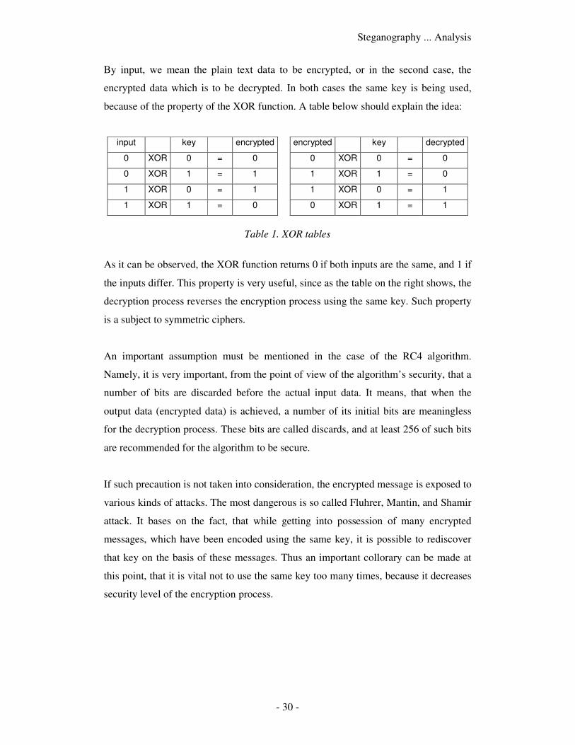
By input, we mean the plain text data to be encrypted, or in the second case, the
encrypted data which is to be decrypted. In both cases the same key is being used,
because of the property of the XOR function. A table below should explain the idea:
input key encrypted encrypted key decrypted
0 XOR 0 = 0 0 XOR 0 = 0
0 XOR 1 = 1 1 XOR 1 = 0
1 XOR 0 = 1 1 XOR 0 = 1
1 XOR 1 = 0 0 XOR 1 = 1
Table 1. XOR tables
As it can be observed, the XOR function returns 0 if both inputs are the same, and 1 if
the inputs differ. This property is very useful, since as the table on the right shows, the
decryption process reverses the encryption process using the same key. Such property
is a subject to symmetric ciphers.
An important assumption must be mentioned in the case of the RC4 algorithm.
Namely, it is very important, from the point of view of the algorithm’s security, that a
number of bits are discarded before the actual input data. It means, that when the
output data (encrypted data) is achieved, a number of its initial bits are meaningless
for the decryption process. These bits are called discards, and at least 256 of such bits
are recommended for the algorithm to be secure.
If such precaution is not taken into consideration, the encrypted message is exposed to
various kinds of attacks. The most dangerous is so called Fluhrer, Mantin, and Shamir
attack. It bases on the fact, that while getting into possession of many encrypted
messages, which have been encoded using the same key, it is possible to rediscover
that key on the basis of these messages. Thus an important collorary can be made at
this point, that it is vital not to use the same key too many times, because it decreases
security level of the encryption process.
Steganography ... Analysis
- 31 -
3.2.3 Cryptographic services under MS Windows
Since the operating system, which is intended to cope with the desired tasks, is a
Microsoft Windows operating system, it would be worth knowing, if there are any
tools supported by MS Windows, which cover some of the above mentioned
encryption algorithms. In fact, a technology called CryptoAPI has been implemented
under Microsoft Windows, thus it may be interesting to describe this tool, in order to
check if it may come in handy.
CryptoAPI is a technology supported by the Microsoft Windows operating system. It
provides a way for applications to get cryptographic services, like for example
encryption and decryption of data. This technology supports special modules, called
Cryptographic Service Providers, or shortly CSPs, which actually support all
necessary cryptographic functions. They perform cryptographic operations, generate,
and store private keys.
To generalize the Cryptographic Service Providers, they can be divided into three
major categories:
1. Hardware based
2. Software based
3. Combined - partially hardware and software based
Because private keys and cryptographic operations are isolated from the operating
system in hardware based CSPs, we may say that such convention is more secure than
the software based cryptography. However, using hardware based cryptographic
functions may have its disadvantages. First of all, storage space of such hardware is
limited, so is the calculation power. It may take longer time for hardware based CSPs
to generate keys. Hardware based CSPs are usually used when extreme security is
required, for example while logging with use of smart cards. Combined Cryptographic
Service Providers usually involve some hardware unit (like smart card verifier),
together with fast computation speed achieved by use of some software.
Steganography ... Analysis
- 32 -
It is worth mentioning, that all CSPs, which are intended to be used under Microsoft
Windows operating system, need to obtain a certificate from Microsoft, otherwise
they will simply not work under this system.
The following Cryptographic Service Providers are being supported under Microsoft
Windows operating system:
� Microsoft Base Cryptographic Provider - provides basic cryptographic
functions, uses RSA technology, is not subject to United States government
cryptography export restrictions and therefore can be exported to other
countries
� Microsoft Enhanced Cryptographic Provider - it is similar to the previous one,
but provides additional algorithms thus increasing security, however is
restricted by the US government
� Microsoft DSS Cryptographic Provider - supports signature verification and
electronic data signing by using SHA and DSA algorithms. It is not restricted
� Microsoft Base DSS and Diffie-Hellman Cryptographic Provider - supports
similar function as the previous one, provides additionally Diffie-Hellman key
exchange. It is restricted
� Schannel Cryptographic Providers - support data integrity, session key
exchange, and authentication while using SSL and TLS protocols. These
providers are not restricted by any international organizations
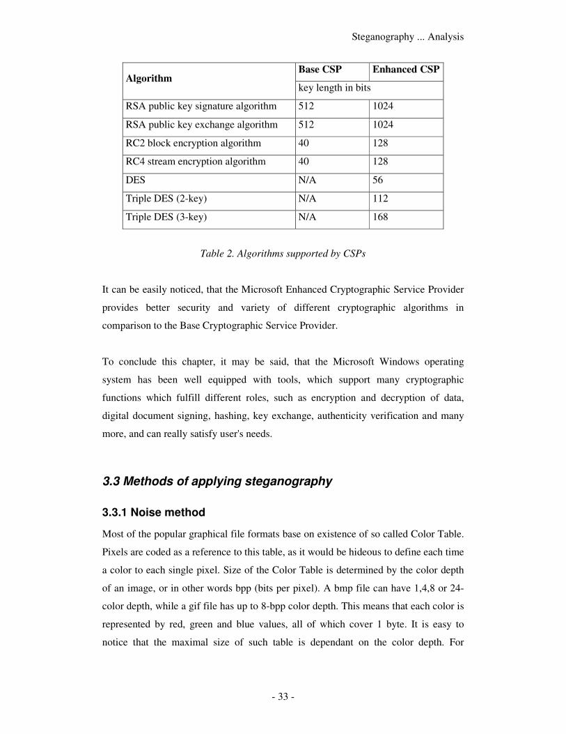
It can be noticed, that providers, which support better cryptographic functions, are
usually subjects to United States government cryptography export restrictions. A
question arises, what kind of functionality is provided by both kind of CSPs. It can be
shown on example of the Microsoft Base CSP and Microsoft Enhanced CSP. A table
below shows different algorithms used by those providers, as well as supported key
lengths:
Steganography ... Analysis
- 33 -
Base CSP Enhanced CSP Algorithm
key length in bits
RSA public key signature algorithm 512 1024
RSA public key exchange algorithm 512 1024
RC2 block encryption algorithm 40 128
RC4 stream encryption algorithm 40 128
DES N/A 56
Triple DES (2-key) N/A 112
Triple DES (3-key) N/A 168
Table 2. Algorithms supported by CSPs
It can be easily noticed, that the Microsoft Enhanced Cryptographic Service Provider
provides better security and variety of different cryptographic algorithms in
comparison to the Base Cryptographic Service Provider.
To conclude this chapter, it may be said, that the Microsoft Windows operating
system has been well equipped with tools, which support many cryptographic
functions which fulfill different roles, such as encryption and decryption of data,
digital document signing, hashing, key exchange, authenticity verification and many
more, and can really satisfy user's needs.
3.3 Methods of applying steganography
3.3.1 Noise method
Most of the popular graphical file formats base on existence of so called Color Table.
Pixels are coded as a reference to this table, as it would be hideous to define each time
a color to each single pixel. Size of the Color Table is determined by the color depth
of an image, or in other words bpp (bits per pixel). A bmp file can have 1,4,8 or 24-
color depth, while a gif file has up to 8-bpp color depth. This means that each color is
represented by red, green and blue values, all of which cover 1 byte. It is easy to
notice that the maximal size of such table is dependant on the color depth. For
Steganography ... Analysis
- 34 -
example, for a file with 24-bpp color depth, the number of all possible combinations
of the RGB values is equal to 224
, which equals roughly 16 million colors.
The concept is, to make use of such Color Table, by using the LSB (least significant
bit) of each RGB color. Such concept is an idea of using the noise of an image.
Imagine, that one of the components, say red, has the following bit representation in
the Color Table: 11011011, which makes a total of 219. Suppose the last bit would
change its value from 1 to 0. The obtained representation would be: 11011010,
equaling 218. Such small difference of color intensity cannot be detected by human’s
eye. Thus, such approach bases on using the noise. Having n colors used in the Color
Table, we obtain possible 3*n bits, to place additional information into. If the number
of colors used in the image is small, it may be necessary to use not only one LSB, but
two or more. However, this approach would rapidly decrease quality of the image,
making it more exposable for a potential attacker.
The noise method does not apply only to a palette of an image. In case of files with
24-bpp color depth, such as BMP files for example, there cannot be a color table
present inside the file. The reason is obvious. In order to make use of such a palette,
the size of the image would have to be at least 16 Megabytes, which is enormous. In
this case no palette is used and data is written as a sequence of pixels, represented by
triplets of RGB values. So, in fact, the number of pixel to store information into,
instead of using a color table, will be equal to: 3*image_width*image_height. So, the
bigger the dimensions of the image are, the more information may be stored inside it.
3.3.2 Block methods
Apart from noise method described above, another approach may be used. Namely,
various block methods may be applied to store information. But before explaining the
idea, an important assumption must be mentioned. Namely, security level of a noise
method is much higher than the one present in block methods. The conclusion is, that
these methods may be used only as supplements to the above described techniques
and will not provide as much security as the noise method.
Steganography ... Analysis
- 35 -
The idea of block methods has nothing to do with hiding information inside LSB of a
sequence of bytes. The concept is to make use of special markers, extensions and
other blocks, which do not hold any important information from the point of file
viewing, but they may be of benefit as far as the project’s goal is concerned. The first
possibility arises while taking into consideration modification of GIF files. A property
of a GIF89a may be used, which are extensions. Comment extension holds plain text
in human-readable form. Each of these blocks has limited length of 255 characters,
however the number of blocks in such file is not limited. Thus this makes a perfect
opportunity to make use of such property and put encrypted information inside
comment extensions of a GIF89a file.
A similar approach may be used in case of JPEG files. As described in the analysis
section, a JPEG file has a structure built from blocks, which are called markers. Each
of these markers has a marker indicator and a length field, which allow detecting what
kind of block this is and where the following block resides. This gives us an
opportunity to attach a block inside the JPEG file structure, which may contain the
encrypted information. However, if such block is not recognizable by some graphical
application, than in case of saving this file under this program the attached watermark
may disappear. So, this type of non-recognizable block will be denoted as a weak
watermark.
There are however some places inside a JPEG file structure, which allow storing some
additional information, without having to take a risk of an accidental erase. This may
for example be space contained in the first marker of each JPEG file. The application
marker (or shortly APP0) contains fields, which allow storing a thumbnail of an
image. There are two bytes responsible for keeping width and height of a thumbnail.
The picture itself is not compressed and represented by a sequence of RGB triplets.
The maximum size of the APP0 marker is limited to 64 Kilobytes, which allows
storing almost 64 Kb inside the thumbnail image field.
- 36 -
IV. Project description
4.1 Implementation choices
4.1.1 Programming platform
The application requires use of graphical user interface. Moreover, it must run under
Microsoft Windows operating system. In general, two possible programming
platforms were considered at the beginning of the implementation phase: MFC and
Visual Basic, both contained in Microsoft Visual Studio. Finally, Visual Basic was
chosen as the programming platform. Its programming interface is very used-friendly,
it contains many useful tools, most of which are of type – put on form/program
event/use with ease. Programming using MFC is not that simple, however one can
achieve almost the same effect.
4.1.2 Application type
As stated before, the application requires being of visual type, because the user must
be able to observe how the image has changed after it has been processed. It should
also be equipped with tools making it easy for the user to be able to open and save
files, display them on the screen and observe how each change affects the images.
That is why it should support many different file types to increase functionality of the
application. The choice of available cryptographic functions should also be quite
spread out, since the user might want to choose different functions for encryption of
different file types.
4.1.3 Application simplicity vs. high functionality
The application has to fulfill two important goals. At first, and the most important one
too, should be its functionality. It is essential, that the program is equipped with many
functions and is able to perform all of the desired activities without any errors. The
second important thing is simplicity of the application. The user must be able to
perform the desired task without any problems or hesitation while he tries to achieve
his goal, in this case encrypt information, and put it inside an image. He must not have
Steganography ... Project description
- 37 -
any doubts of what he is doing and how he should achieve it. That is why the
overlook of the application must be simple and user-friendly. It should also be
equipped with some help features, such as context help, or some general information
on all of the functions, which may be used.
4.1.4 Installation
As it has been already stated in the Software requirements chapter, the application
should run under different versions of MS Windows operating system, starting from
MS Windows ’98 and finishing on Windows XP. Moreover, it was assumed, that
there should be no installation package, as it is usually much bigger in size and makes
many unnecessary modifications to the system’s registry file. The executable file of
the application itself is quite small and may be run even from a floppy disk.
However, on some older systems, like Windows ’98 for instance, a problem with
running the program may actually occur. Namely, there is one library, which needs to
be registered, before being able to execute and use the application. It should be
already registered under systems like Windows 2000 or XP, but one could never
know. Moreover, the user should not mess with such operation like registering a
library, so a script named register.bat has been created to minimize the effort of
performing the desired task. The control, which needs to be registered, is named
comdlg32.ocx. It is responsible for performing all operations connected with Common
Dialog Control, which will be described in the following chapter.
The idea to register a library makes the most of an executable file named
regsvr32.exe, which should be present on all Windows systems with 32-bit
environment. This application allows registering services such as dynamic link
libraries (dlls) or ocx files. The problem arises, because on different operating systems
the regsvr32.exe file is placed in different directories. On Windows 98 it is .../system/,
while on Windows NT or XP it is named .../system32/. More problem arise, while on
Windows 98 and XP the default Windows directory is C:\Windows, while on
Windows NT it is C:\WinNT. The problem is solved with help of simple instructions
combined with reading some environment system variables.
Steganography ... Project description
- 38 -
At first, two variables are being set to hold paths to proper locations of the
regsvr32.exe file, depending on the location of Windows directory, which is held on
system variable windir, which is present on all of the MS Windows operating
systems:
ms-dos script code
set NTFile=%windir%\system32\regsvr32.exe
set noNTFile=%windir%\system\regsvr32.exe
Then, the name of the library is being read and a variable named os is being tested if it
contains the Windows_NT string:
ms-dos script code
set LibFile=%1
if "%os%"=="Windows_NT" goto ISNT
More instructions follow, but probably the most important one will be the one
responsible for registering the control. It is being achieved in such way:
ms-dos script code
%NTFile% /s %LibFile%
if errorlevel 1 goto ERR
The s flag is set to make sure that no message box pops up; all comments are
presented to the user within the console window. If the process of registering the
control is unsuccessful, a corresponding instruction will be executed and a proper
error message will be displayed. Finally, all created variables must be removed from
the system environment, so following calls are executed:
ms-dos script code
set NTFile=
set noNTFile=
set LibFile=
Steganography ... Project description
- 39 -
The above instructions remove the variables, so no unnecessary rubbish is left within
the system. The library has been now registered and the program may be executed
with no error message to be displayed.
4.2 The main process
4.2.1 Attaching information to an image
� opening / reading / displaying an image
At first, when we wish to perform any operation on any file, we have to open it
for reading. Thanks to special components, which can be included in a Visual
Basic Project, usage of some forms especially designed for management of file
reading/writing can be implemented much easier. A control named Microsoft
Common Dialog Control has been added to the Project. It has been designed as
a standard form, which supports the above-mentioned conditions. It has been
programmed to support opening and saving certain file types and the code with
which it has been set is as following:
vb code
With CommonDialog1
.DialogTitle = "Open"
.InitDir = App.Path
.Filter = "OS/2 Bitmap Files (*.bmp)|*.bmp|_
Graphics Interchange Format (*.gif)|*.gif|_
JPEG File Interchange Format
(*.jpg,*.jpeg)|*.jpg;*.jpeg"
.ShowOpen
End With
The above With statement allows setting for example the initial directory or
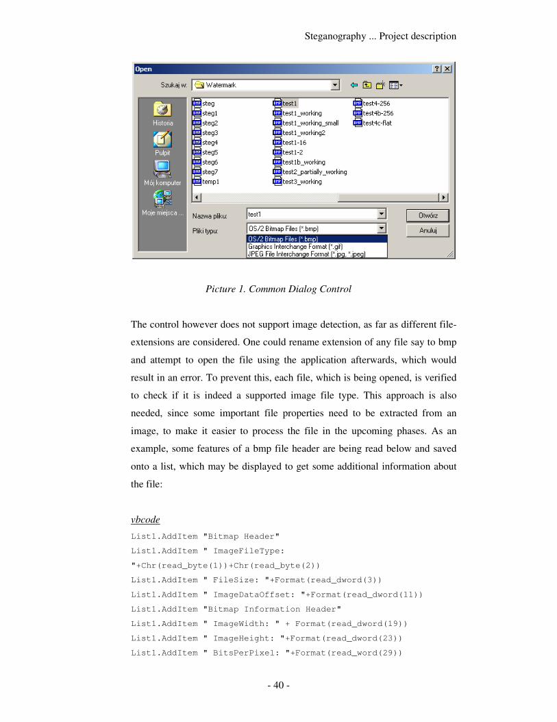
the filter for the file extensions. The form looks as follows when displayed:
Steganography ... Project description
- 40 -
Picture 1. Common Dialog Control
The control however does not support image detection, as far as different file-
extensions are considered. One could rename extension of any file say to bmp
and attempt to open the file using the application afterwards, which would
result in an error. To prevent this, each file, which is being opened, is verified
to check if it is indeed a supported image file type. This approach is also
needed, since some important file properties need to be extracted from an
image, to make it easier to process the file in the upcoming phases. As an
example, some features of a bmp file header are being read below and saved
onto a list, which may be displayed to get some additional information about
the file:
vbcode
List1.AddItem "Bitmap Header"
List1.AddItem " ImageFileType:
"+Chr(read_byte(1))+Chr(read_byte(2))
List1.AddItem " FileSize: "+Format(read_dword(3))
List1.AddItem " ImageDataOffset: "+Format(read_dword(11))
List1.AddItem "Bitmap Information Header"
List1.AddItem " ImageWidth: " + Format(read_dword(19))
List1.AddItem " ImageHeight: "+Format(read_dword(23))
List1.AddItem " BitsPerPixel: "+Format(read_word(29))
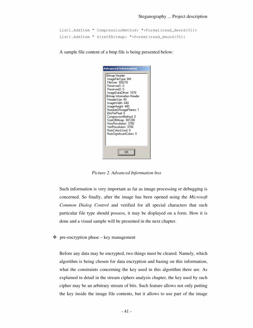
Steganography ... Project description
- 41 -
List1.AddItem " CompressionMethod: "+Format(read_dword(31))
List1.AddItem " SizeOfBitmap: "+Format(read_dword(35))
A sample file content of a bmp file is being presented below:
Picture 2. Advanced Information box
Such information is very important as far as image processing or debugging is
concerned. So finally, after the image has been opened using the Microsoft
Common Dialog Control and verified for all special characters that such
particular file type should possess, it may be displayed on a form. How it is
done and a visual sample will be presented in the next chapter.
� pre-encryption phase – key management
Before any data may be encrypted, two things must be cleared. Namely, which
algorithm is being chosen for data encryption and basing on this information,
what the constraints concerning the key used in this algorithm there are. As
explained in detail in the stream ciphers analysis chapter, the key used by such
cipher may be an arbitrary stream of bits. Such feature allows not only putting
the key inside the image file contents, but it allows to use part of the image
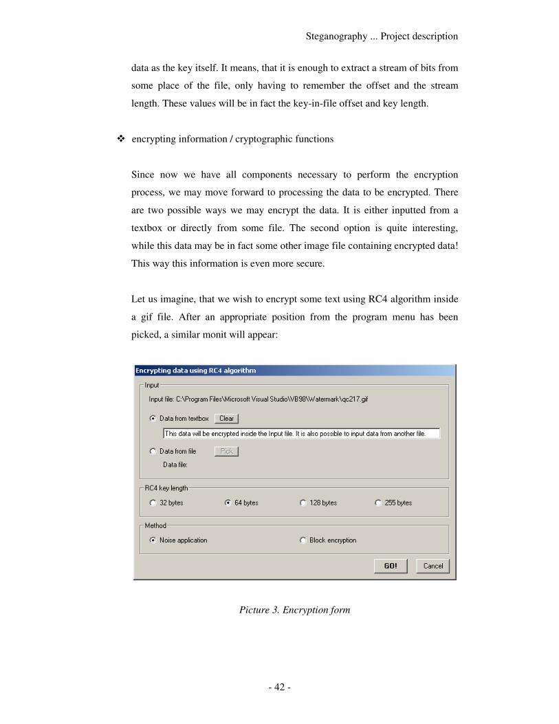
Steganography ... Project description
- 42 -
data as the key itself. It means, that it is enough to extract a stream of bits from
some place of the file, only having to remember the offset and the stream
length. These values will be in fact the key-in-file offset and key length.
� encrypting information / cryptographic functions
Since now we have all components necessary to perform the encryption
process, we may move forward to processing the data to be encrypted. There
are two possible ways we may encrypt the data. It is either inputted from a
textbox or directly from some file. The second option is quite interesting,
while this data may be in fact some other image file containing encrypted data!
This way this information is even more secure.
Let us imagine, that we wish to encrypt some text using RC4 algorithm inside
a gif file. After an appropriate position from the program menu has been
picked, a similar monit will appear:
Picture 3. Encryption form
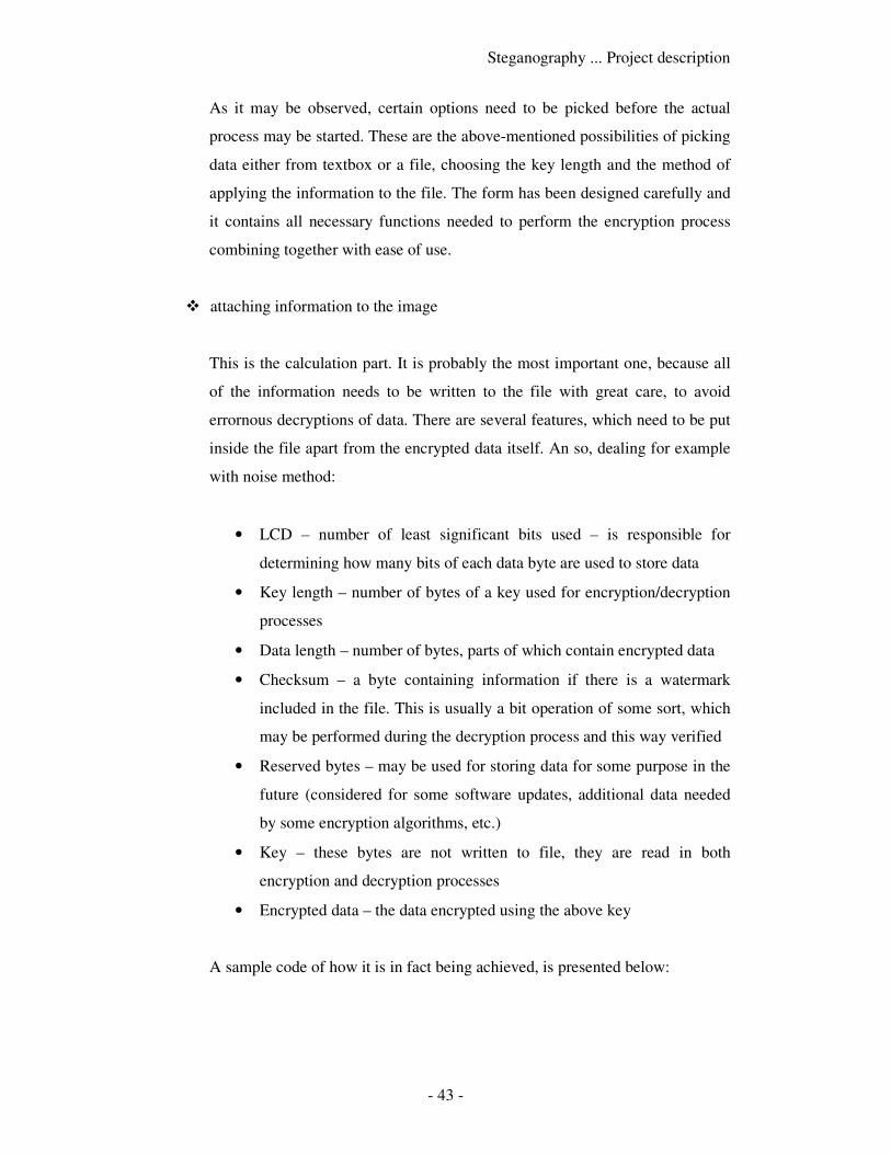
Steganography ... Project description
- 43 -
As it may be observed, certain options need to be picked before the actual
process may be started. These are the above-mentioned possibilities of picking
data either from textbox or a file, choosing the key length and the method of
applying the information to the file. The form has been designed carefully and
it contains all necessary functions needed to perform the encryption process
combining together with ease of use.
� attaching information to the image
This is the calculation part. It is probably the most important one, because all
of the information needs to be written to the file with great care, to avoid
errornous decryptions of data. There are several features, which need to be put
inside the file apart from the encrypted data itself. An so, dealing for example
with noise method:
• LCD – number of least significant bits used – is responsible for
determining how many bits of each data byte are used to store data
• Key length – number of bytes of a key used for encryption/decryption
processes
• Data length – number of bytes, parts of which contain encrypted data
• Checksum – a byte containing information if there is a watermark
included in the file. This is usually a bit operation of some sort, which
may be performed during the decryption process and this way verified
• Reserved bytes – may be used for storing data for some purpose in the
future (considered for some software updates, additional data needed
by some encryption algorithms, etc.)
• Key – these bytes are not written to file, they are read in both
encryption and decryption processes
• Encrypted data – the data encrypted using the above key
A sample code of how it is in fact being achieved, is presented below:
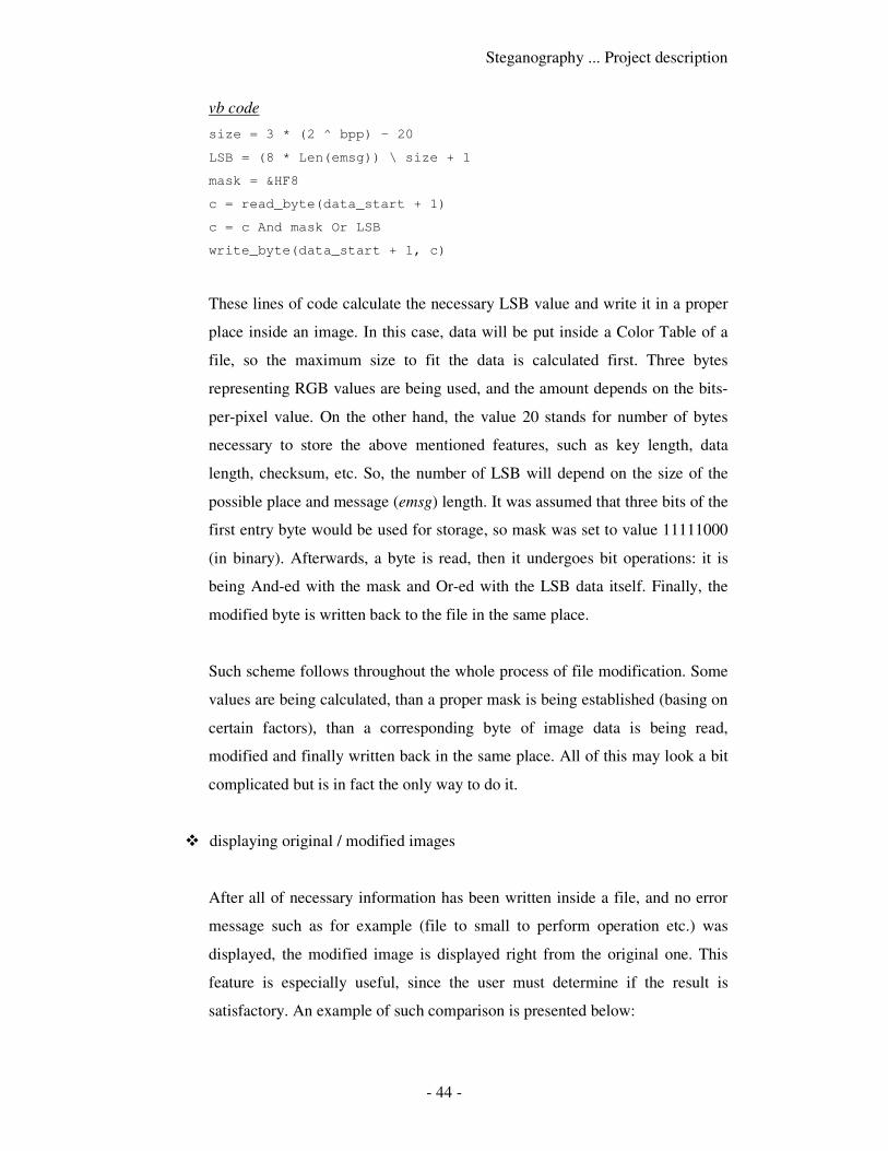
Steganography ... Project description
- 44 -
vb code
size = 3 * (2 ^ bpp) – 20
LSB = (8 * Len(emsg)) \ size + 1
mask = &HF8
c = read_byte(data_start + 1)
c = c And mask Or LSB
write_byte(data_start + 1, c)
These lines of code calculate the necessary LSB value and write it in a proper
place inside an image. In this case, data will be put inside a Color Table of a
file, so the maximum size to fit the data is calculated first. Three bytes
representing RGB values are being used, and the amount depends on the bits-
per-pixel value. On the other hand, the value 20 stands for number of bytes
necessary to store the above mentioned features, such as key length, data
length, checksum, etc. So, the number of LSB will depend on the size of the
possible place and message (emsg) length. It was assumed that three bits of the
first entry byte would be used for storage, so mask was set to value 11111000
(in binary). Afterwards, a byte is read, then it undergoes bit operations: it is
being And-ed with the mask and Or-ed with the LSB data itself. Finally, the
modified byte is written back to the file in the same place.
Such scheme follows throughout the whole process of file modification. Some
values are being calculated, than a proper mask is being established (basing on
certain factors), than a corresponding byte of image data is being read,
modified and finally written back in the same place. All of this may look a bit
complicated but is in fact the only way to do it.
� displaying original / modified images
After all of necessary information has been written inside a file, and no error
message such as for example (file to small to perform operation etc.) was
displayed, the modified image is displayed right from the original one. This
feature is especially useful, since the user must determine if the result is
satisfactory. An example of such comparison is presented below:
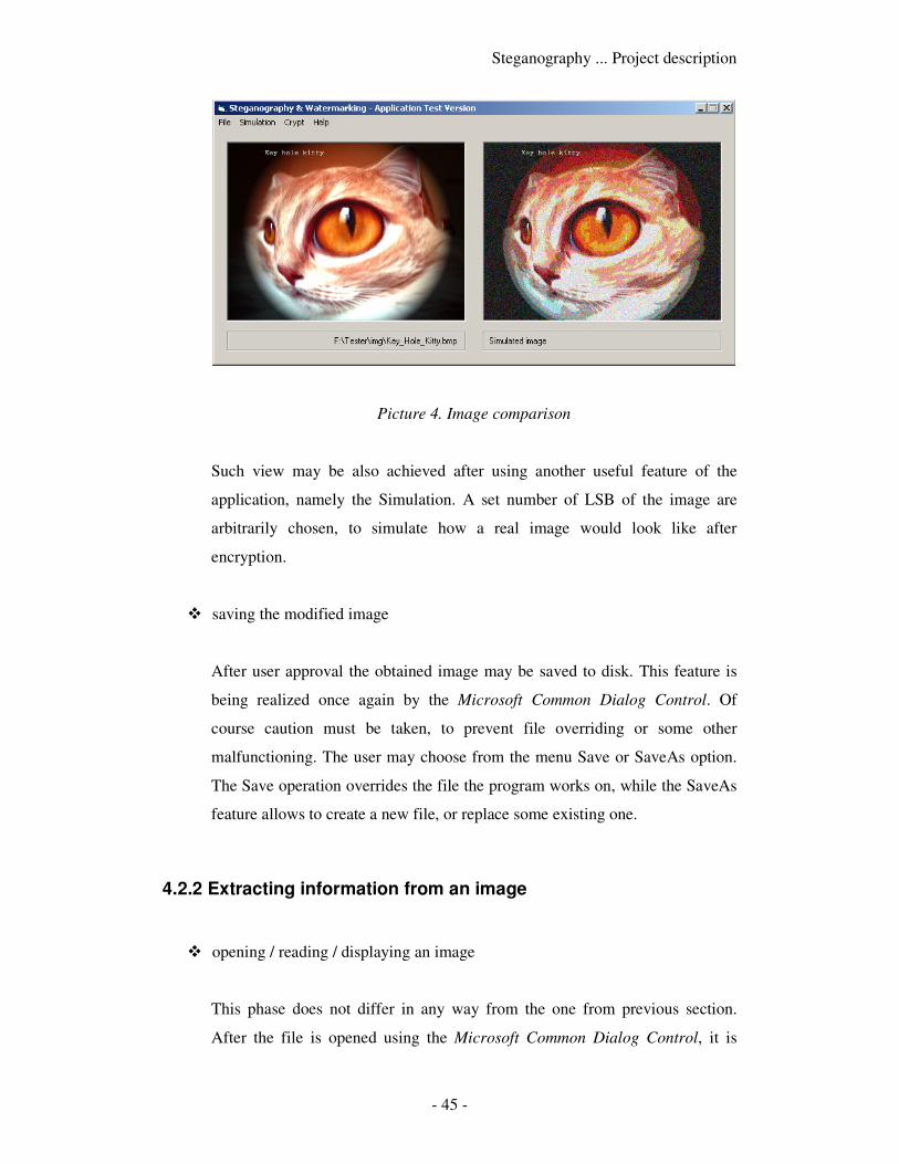
Steganography ... Project description
- 45 -
Picture 4. Image comparison
Such view may be also achieved after using another useful feature of the
application, namely the Simulation. A set number of LSB of the image are
arbitrarily chosen, to simulate how a real image would look like after
encryption.
� saving the modified image
After user approval the obtained image may be saved to disk. This feature is
being realized once again by the Microsoft Common Dialog Control. Of
course caution must be taken, to prevent file overriding or some other
malfunctioning. The user may choose from the menu Save or SaveAs option.
The Save operation overrides the file the program works on, while the SaveAs
feature allows to create a new file, or replace some existing one.
4.2.2 Extracting information from an image
� opening / reading / displaying an image
This phase does not differ in any way from the one from previous section.
After the file is opened using the Microsoft Common Dialog Control, it is
Steganography ... Project description
- 46 -
being read for characters and data specific for its file extension. If the received
information is correct, the file is displayed on the form.
� watermark presence verification
To be able to process with further steps of the extraction phase, we must first
determine if the image contains a watermark. To verify its presence, we should
use the checksum field, which has been set during the attachment phase. This
field contains a value which has been set on a basis of certain bit operations,
and so:
vb code
c = read_byte(some_offs + 1) Xor read_byte(some_offs + 2)
checksum = read_byte(other_offs)
The above code is used to verify the checksum. The bit operation used during
the attachment phase is made once again, but this time the checksum is not
written but read from the file. If both of the above values are equal, than there
is high probability that the image contains a watermark. We cannot be sure
with 100% that it is really true, because it might happen that these values are
equal by coincidence, however such case should not happen very often.
In fact, probability of occurrence of such case may be easily calculated.
Namely, if a byte consisting of eight bits is considered, all possible
combinations of bit values have to be taken into consideration. There are 28
combinations, making a total of 256 possibilities. Thus, probability that a
watermark is detected and is in fact not present inside an image is equal to P(1
byte) = 1 / 256, which makes it roughly 0.39 %. This result is quite
satisfactory, however one could consider using two or more bytes as checksum
fields. In case of two bytes usage, the probability would be equal to P(2 bytes)
= (1 / 256)2, which is equal to mere 0.001 %.
In case of the noise method, the checksum is hidden inside noise of the image,
because there is no other place to store the checksum information. Otherwise,

Steganography ... Project description
- 47 -
such information could be probably stored in some additional block, but such
concept should not be used within the noise method.
� extracting the data
This step is similar to the attachment step, however it’s made ‘backwards’.
Certain factors are extracted from the file, and some are calculated basing on
the obtained values:
• Checksum – assuming that its verification is positive, following
extractions may follow
• LSB – determines how many bits of each data byte are used to store
data
• Key length – number of bytes of a key which will be used for
decryption
• Data length – number of bytes, parts of which contain encrypted data
• Key – corresponding bytes which are read from the file, which must be
identical with these used for encryption
• Encrypted data – the data encrypted using the above key, bases on
obtained value of LSB
� decrypting the data
Having extracted all necessary values from during the previous step, we may
follow with data decryption. Since stream ciphers are used, the key used for
decryption is exactly the same as the one used for encryption. So, the process
of decryption is almost the same as encryption, differing only on the input
stream. In case of encryption it was plain text or a file we wished to encrypt, in
the second case it will be the encrypted stream itself.
After having chosen an appropriate option from the menu, which allows
decrypting data, a form will appear, which will allow the user to choose form
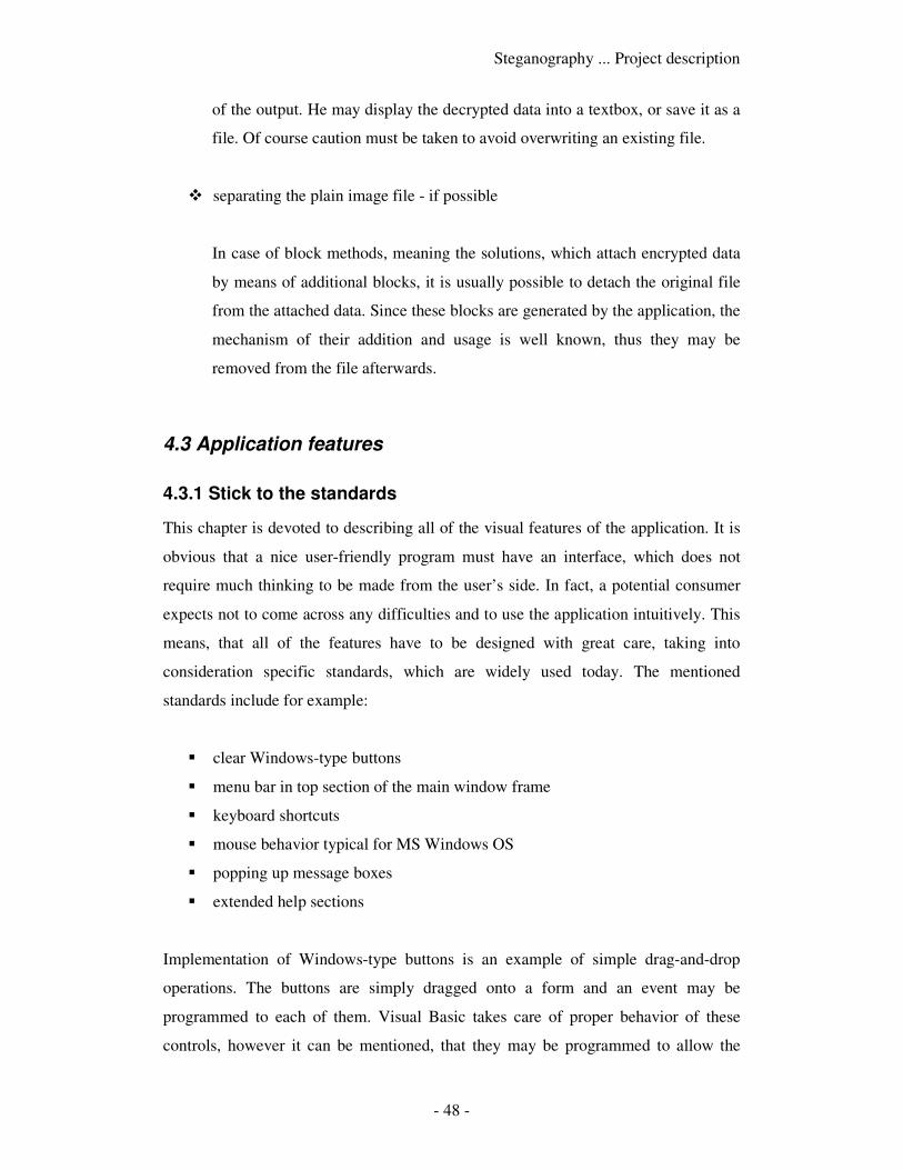
Steganography ... Project description
- 48 -
of the output. He may display the decrypted data into a textbox, or save it as a
file. Of course caution must be taken to avoid overwriting an existing file.
� separating the plain image file - if possible
In case of block methods, meaning the solutions, which attach encrypted data
by means of additional blocks, it is usually possible to detach the original file
from the attached data. Since these blocks are generated by the application, the
mechanism of their addition and usage is well known, thus they may be
removed from the file afterwards.
4.3 Application features
4.3.1 Stick to the standards
This chapter is devoted to describing all of the visual features of the application. It is
obvious that a nice user-friendly program must have an interface, which does not
require much thinking to be made from the user’s side. In fact, a potential consumer
expects not to come across any difficulties and to use the application intuitively. This
means, that all of the features have to be designed with great care, taking into
consideration specific standards, which are widely used today. The mentioned
standards include for example:
� clear Windows-type buttons
� menu bar in top section of the main window frame
� keyboard shortcuts
� mouse behavior typical for MS Windows OS
� popping up message boxes
� extended help sections
Implementation of Windows-type buttons is an example of simple drag-and-drop
operations. The buttons are simply dragged onto a form and an event may be
programmed to each of them. Visual Basic takes care of proper behavior of these
controls, however it can be mentioned, that they may be programmed to allow the
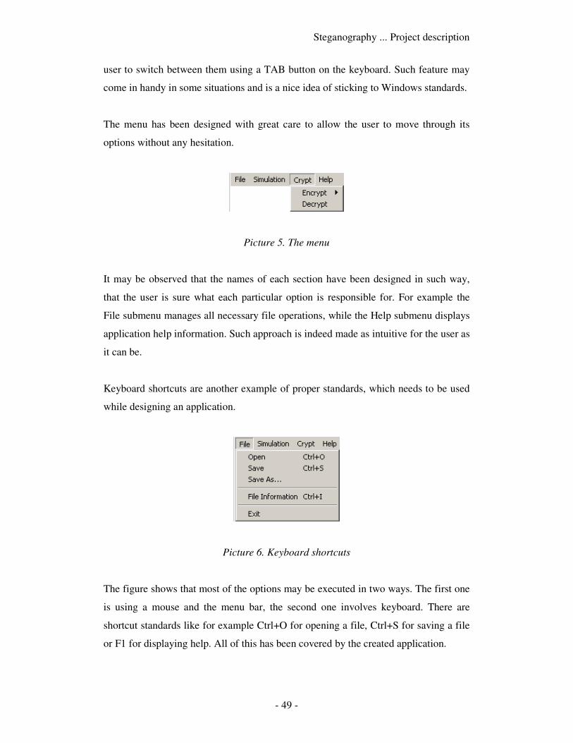
Steganography ... Project description
- 49 -
user to switch between them using a TAB button on the keyboard. Such feature may
come in handy in some situations and is a nice idea of sticking to Windows standards.
The menu has been designed with great care to allow the user to move through its
options without any hesitation.
Picture 5. The menu
It may be observed that the names of each section have been designed in such way,
that the user is sure what each particular option is responsible for. For example the
File submenu manages all necessary file operations, while the Help submenu displays
application help information. Such approach is indeed made as intuitive for the user as
it can be.
Keyboard shortcuts are another example of proper standards, which needs to be used
while designing an application.
Picture 6. Keyboard shortcuts
The figure shows that most of the options may be executed in two ways. The first one
is using a mouse and the menu bar, the second one involves keyboard. There are
shortcut standards like for example Ctrl+O for opening a file, Ctrl+S for saving a file
or F1 for displaying help. All of this has been covered by the created application.
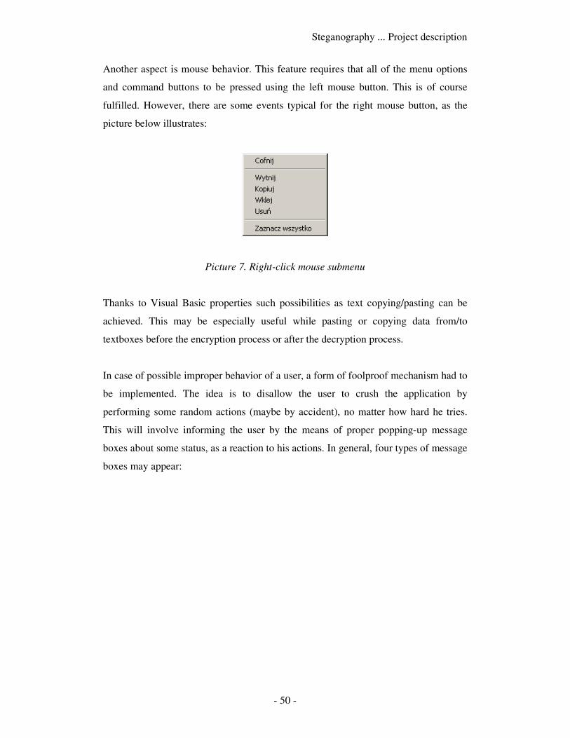
Steganography ... Project description
- 50 -
Another aspect is mouse behavior. This feature requires that all of the menu options
and command buttons to be pressed using the left mouse button. This is of course
fulfilled. However, there are some events typical for the right mouse button, as the
picture below illustrates:
Picture 7. Right-click mouse submenu
Thanks to Visual Basic properties such possibilities as text copying/pasting can be
achieved. This may be especially useful while pasting or copying data from/to
textboxes before the encryption process or after the decryption process.
In case of possible improper behavior of a user, a form of foolproof mechanism had to
be implemented. The idea is to disallow the user to crush the application by
performing some random actions (maybe by accident), no matter how hard he tries.
This will involve informing the user by the means of proper popping-up message
boxes about some status, as a reaction to his actions. In general, four types of message
boxes may appear:
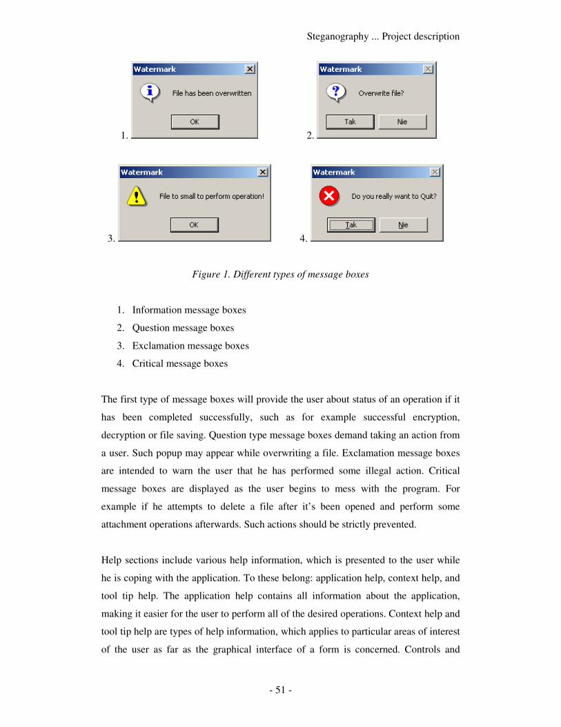
Steganography ... Project description
- 51 -
1. 2.
3. 4.
Figure 1. Different types of message boxes
1. Information message boxes
2. Question message boxes
3. Exclamation message boxes
4. Critical message boxes
The first type of message boxes will provide the user about status of an operation if it
has been completed successfully, such as for example successful encryption,
decryption or file saving. Question type message boxes demand taking an action from
a user. Such popup may appear while overwriting a file. Exclamation message boxes
are intended to warn the user that he has performed some illegal action. Critical
message boxes are displayed as the user begins to mess with the program. For
example if he attempts to delete a file after it’s been opened and perform some
attachment operations afterwards. Such actions should be strictly prevented.
Help sections include various help information, which is presented to the user while
he is coping with the application. To these belong: application help, context help, and
tool tip help. The application help contains all information about the application,
making it easier for the user to perform all of the desired operations. Context help and
tool tip help are types of help information, which applies to particular areas of interest
of the user as far as the graphical interface of a form is concerned. Controls and

Steganography ... Project description
- 52 -
objects, which reside on a form, should be “monitored” by the application while the
user stops a mouse over them. In such cases he may want to read some information on
a particular control and it is usually displayed in a yellow rectangular box close to the
mouse cursor. This really helps the user moving through the program interface.
4.3.2 Image preview
The idea of the project was to confront the initial image and the modified one, to
make it possible for the user to choose if the result of data attachment satisfies his
needs. This feature is especially useful in case of the noise method, because the
distortions may be too big for the user to accept. On the other hand, the user should
have a chance to see if an applied block method did not cause any damage to the
image and if it is displayed correctly. So, the conclusion is as following – the user
should be able to observe both of the images. It could be achieved either by switching
the both images located in the same place, or by displaying the images close to each
other to have a clear real-time view. The second option has been chosen to minimize
user’s interference with image displaying. Moreover, the images have been presented
as miniatures, in two 320x240 picture boxes, as the image below shows:
Picture 8. Image scaling
Steganography ... Project description
- 53 -
To display the miniatures, the images have to be scaled before displaying. Basic code
for achieving this is presented below:
vb code
Picture1(ind).Cls
Picture2 = LoadPicture(file_name)
Picture1(ind).PaintPicture Picture2, hor_offs, ver_offs,_
Int(320 * 15 * hor), Int(240 * 15 * ver)
Picture1 control represents an indexed picture box (0 = initial file, 1 = modified file).
Picture2 is a hidden control, which holds a full image preview. The PaintPicture
method allows making the most of the content of the Picture2 control, and displaying
it after modifications in a proper Picture1 box. The hor_offs and ver_offs represent
offset of the picture, which is being displayed. They are used if one of the coordinates
(width or height) is smaller than the corresponding size of 320x240 picture box. The
hor and ver values represent the actual size of a corresponding coordinate, which is
responsible for how many times the actual image is being shrinked (these values are
calculated earlier and base on information obtained from the image structure such as
image_width and image_height). The magic constant 15 stands for pixel size under
Visual Basic scale (1 pixel equals 15 units).
4.3.3 Method simulation
As mentioned in one of the preceding chapters, it is especially helpful to be able to
present to the user the outcome of a data attachment process, before having to perform
the actual task, meaning encryption process, file modification, file saving, etc. This is
achieved by means of simulation. The user may choose an option from the menu bar,
to see what result would a particular event have on a file he wishes to modify.
The event may be for example simulating the possible outcome of performing the
noise method on an image. It is possible to choose the number of least significant bits
of each byte, which will be used as information carriers. The actual simulation process
intends to cover the place responsible for data attachment using a random bit stream.
It is being achieved like so:
Steganography ... Project description
- 54 -
vb code
mask2 = 0
For j = LSB To 7
mask2 = mask2 + 2 ^ j
Next j
// loop start ...
mask = 0
For n = 0 To LSB - 1
mask = mask + Int(2 * Rnd) * 2 ^ n
Next n
c = read_byte(...)
c = c And mask2 Or mask
write_byte(c)
// loop end
At first a mask called mask2 is established. It will be used to mask all of the HSB
(high significant bits), which will be left out unchanged from each read byte. Then a
loop is executed. Each time, a mask called mask is being calculated, basing on random
values (Rnd parameter). Having the two masks, it is possible to modify a particular
byte. After it has been read, the HSB is kept using the mask2, and additional random
bits are applied using the mask. The loop continues as long as all necessary bytes have
been modified.
The method allows observing simulations of eight different byte fills, starting from 1
bit used, and finishing on all bits used. The results are quite interesting and for some
may be a bit surprising:
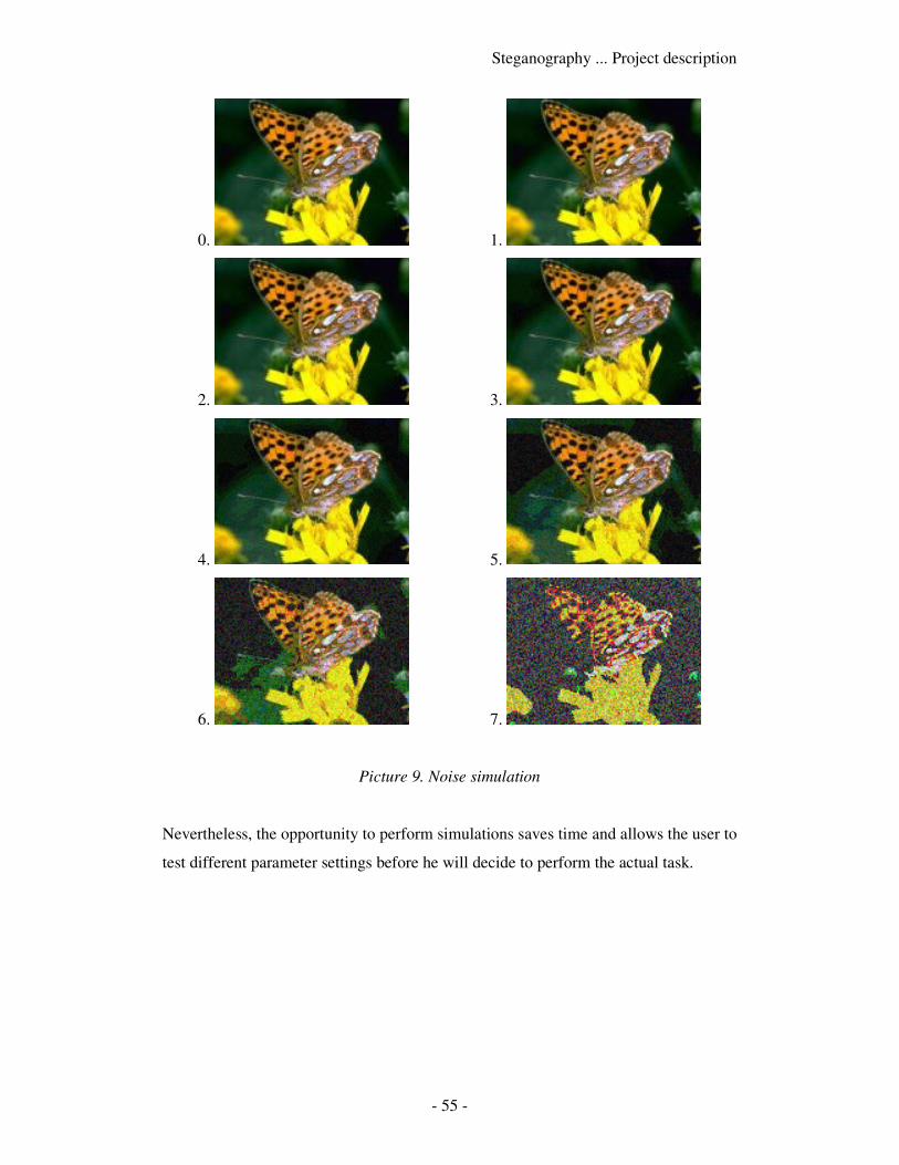
Steganography ... Project description
- 55 -
0. 1.
2. 3.
4. 5.
6. 7.
Picture 9. Noise simulation
Nevertheless, the opportunity to perform simulations saves time and allows the user to
test different parameter settings before he will decide to perform the actual task.
- 56 -
V. Research
The program operates on three most popular graphics file format: BMPs, GIFs and
JPEGs. Thus, a detailed research has to be made, to assure that the program really
fulfills all of the desired tasks and if the application would not crash in some special
conditions. To these conditions belong the following possibilities:
� using extremely small files in order to make it impossible to read a key from
such files, or store any information inside their file structure
� using extremely large files or amounts of data to crash the application
� renaming extensions of files to fool the program’s parser, which checks
throughout fixed sections of each of the file formats
� messing with the file structure in such ways, that afterwards it would not be
recognizable by the parser or will cause malfunctioning of the program
The program has been tested to check if the above-mentioned conditions do not cause
program malfunctioning. The testing platform was Windows 2000 with an AMD
Athlon 1800+ processor and 512 Mb of RAM. Some basic tests have also been made
under Windows 98, to ensure that the application is installed correctly and runs
without any problems.
5.1 Method comparison
A table below presents methods, which are supported by different formats. Each of
the possibilities is characterized by the maximum length of a message to be applied
and a comparison of watermark strength and security for each particular case. These
last two fields determine how each of the methods influences factors important from
the point of the view of project’s thesis. Watermark strength determines how well the
attached information is able to withstand modification of the file by some outside
application. Security tells us how well the data is hidden inside the file. Of course, the
stronger the watermark, and the more secure it is, the better.

Steganography ... Research
- 57 -
File type Characteris-
tics (bpp) Method
Message
length
Watermark
strength Security
BMP 8 Noise under 768 b high high
BMP 24 Noise long / file size
dependant medium high
GIF 8 Noise under 768 b high high
GIF ALL Block
(extensions)
under 64 Kb /
may be more medium low
JPEG ALL Block
(own markers) unlimited low low
JPEG ALL Block
(thumbnail) under 64 Kb medium medium
Table 3. Method comparison
It may be observed, that the most secure methods involve using noise as information
carrier. The possibly worst solution looks to be using own markers block method in a
JPEG file, because these markers are destroyed while opening and saving this file in
most of image editors. However, message length is not limited in any way in this case,
so such method may be also found useful. By low security it is understood that the
attacker would find easy access to blocks containing encrypted information, so the
only thing he would have to do, would be to find a way to decrypt the message.
Distinction among different bits-per-pixel values of BMP files, as it comes to
watermark strength, has been introduced to underline a fact, that it is easier (medium
strength) to destroy file content of a file without a color table (24-bpp BMP), than of
one containing one (8-bpp BMP).
5.2 Processing speed
A sample 24-bpp BMP file of size close to 1 Mb was chosen to test it prior to the
speed of calculations. A precise timing mechanism, implemented within the project
measured the actual encryption and decryption speeds. This process involved reading
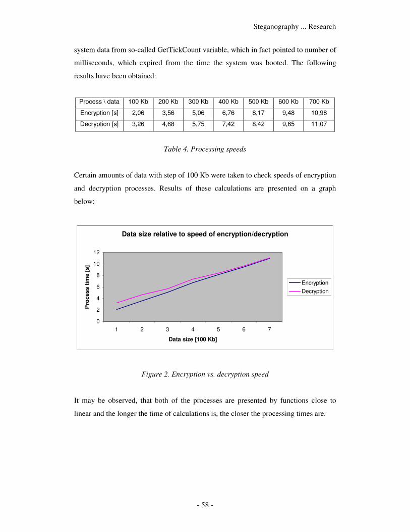
Steganography ... Research
- 58 -
system data from so-called GetTickCount variable, which in fact pointed to number of
milliseconds, which expired from the time the system was booted. The following
results have been obtained:
Process \ data 100 Kb 200 Kb 300 Kb 400 Kb 500 Kb 600 Kb 700 Kb
Encryption [s] 2,06 3,56 5,06 6,76 8,17 9,48 10,98
Decryption [s] 3,26 4,68 5,75 7,42 8,42 9,65 11,07
Table 4. Processing speeds
Certain amounts of data with step of 100 Kb were taken to check speeds of encryption
and decryption processes. Results of these calculations are presented on a graph
below:
Data size relative to speed of encryption/decryption
0
2
4
6
8
10
12
1 2 3 4 5 6 7
Data size [100 Kb]
Pro
cess t
ime [
s]
Encryption
Decryption
Figure 2. Encryption vs. decryption speed
It may be observed, that both of the processes are presented by functions close to
linear and the longer the time of calculations is, the closer the processing times are.
- 59 -
VI. Summary
6.1 Summary of the work
To determine if the goal of the project has been established, one has to review all
assumptions regarding the thesis, as stated in the Aim of the Thesis chapter. The
objective was to prepare an application compatible with MS Windows operating
systems, which would allow maintaining data security as far as privacy of information
is concerned. It was assumed, that the application should perform such operations, as
making the most of graphics file formats and treating them as potential information
carriers, allowing the user to perform all activities concerning encryption and
decryption of data and supporting him in all necessary ways in order to provide him
with a friendly graphical user interface and help information.
The steganographic approach used in the project bases on certain assumptions, which
have been fulfilled throughout careful implementation phase. The watermark, which
is being added to a file, is making the most of two general approaches implemented
by the application. It may be distributed inside the file using noise of the image or
making advantage of certain block structures, which are present in most of the popular
graphics file formats. Both of the methods have their advantages and the user may
choose which one suits him better. In case of noise methods the quality of the image
decreases, however the security level of such approach is very high. On the other
hand, the block methods support far more storage space (mostly unlimited) but
presence of a watermark may be detected easier.
As it states in the Aim of the Thesis, the attached information should not only be
cleverly hidden and distributed inside a file, but it should be encrypted as well to
preserve more security than plain-text information. This concept is especially
important as it comes to block methods, since in case of these, it would be much more
easier to detect and read the block contents. The application supports the user with
tools necessary to perform the desired operations, meaning the encryption, and
decryption of data. It allows the user to choose among various options, such as setting
Steganography ... Summary
- 60 -
the key length, choosing the desired method, or determining the input/output form of
the processed information.
The application combines high functionality with a simple, intuitive graphical user
interface. The user may observe how the encryption process affects the visual
outcome of an image, by the means of a real-time preview. He may also perform a
simulation of a process to save time and try different program settings before
performing the actual task. Number of help features makes the application a tool,
which one may use with real ease and comfort.
To conclude the summary, it must be said with full responsibility, that the desired
goals stated in the Aim of the Thesis have been fulfilled, thus making the created
application a tool worth giving a try.
6.2 Possible expansion chances
6.2.1 Other graphics file formats
Expansion to other graphics file formats is quite simple. The only thing, which needs
to be done, is a detailed analysis of each of the file types. Of course, there may be
some image file format, to which two of the implemented methods may not apply.
However, most of the graphics file formats are built from similar data structures, as
described in the analytical part of the thesis, and contain such elements as headers,
color palettes, and other blocks representing certain properties of image files. This is
surely very convenient from the programmer’s point of view, since the only necessary
thing during the implementation phase would be to read all necessary information
from the file and, basing on this data, adapt it to serve such purposes as the ones
included in the thesis.
Another aspect, which needs to be mentioned, is application of the mentioned
methods along with lossy compression of image data. Such issue is quite an
interesting problem, since it is much more difficult to preserve the attached data,
which is hidden inside compressed information of some file. In this case, one of the
block methods would be found useful, however if it comes to the noise method, one
Steganography ... Summary
- 61 -
could consider tempering with the color table of a file, like in 4- and 8-bpp BMP or
GIF files for instance, and not with the actual compressed data itself. Modification of
the compressed raster data would be much more difficult, since as for example in
JPEG files, the information present before decompression and repeated compression
differs. In such case, one could take into consideration possible loss of parts of the
attached data, since a stream cipher is being used. One of its benefits is that errors in
the decrypted data result in errors in the same places of the encrypted data. Thus, the
rate of error would depend only on how the information can be adapted to face lossy
compression of such files.
6.2.2 Other file formats
Expansion to other file formats apart from graphics file formats may be quite an
interesting topic. Expansion chances depend on how a particular file format can adapt
itself to the proposed methods. The block method is probably more flexible, and may
be adapted to many types of files, however these must be of binary and not of text
type. So, it would probably be possible to use such document formats as popular DOC
and PDF files, because their structure consists of blocks and such concept is similar to
the one used in image file format manipulation. Block methods cannot be applied to
plain-text files like TXT files for instance, since such approach would not differ in
any way from standard encryption procedure and the goal of the thesis was to
combine a steganographic approach together with data encoding.
As it comes to noise method, it cannot be applied to the above mentioned document
formats, since there is no place to treat as a distortion of a file in order to store some
information inside. However, there are some files, which could meet project’s
requirements. To these belong music file formats, such as WAV and MP3 for
instance. In this case, we would not talk about visual distortions of a file like in an
image, but on the other hand rather about audible distortions. Similar to the approach
used in the project, noise of a music file could be used as information carrier.
Probably there would be a similar perception border like in the case of graphics file
formats. Human’s ear would not determine if changes have been made to the file, as
long as it would be a gentle one. Probably after using all space provided for sound
peaks of a music file, the human would hear only a monotonous noise, similarly to the

Steganography ... Summary
- 62 -
case when all LSB of an image have been used, which would result in a completely
grainy picture.
- 63 -
References
[1] Encyclopedia of Graphics File Formats, James D. Murray & William
vanRyper, O’Reilly Associates, Inc., July 1994
[2] GIFs, JPEGs & BMPs: Handling Internet Graphics, Judi N.
Fernandez, MIS Press, 1998
[3] E-forms with Digital Signature, Robert Jastrzębski & Michał Poręba,
B.Sc. Thesis, October 2003
[4] Disappearing Cryptography: Information Hiding: Steganography &
Watermarking, Peter Wayner, Morgan Kaufmann Publishers, 2002
[5] Microsoft Developers Network library
[6] JPEG image compression FAQ, Independent JPEG Group, March 1999
[7] JPEG File Interchange Format Version 1.02, Eric Hamilton, C-Cube
Microsystems, September 1992
[8] Graphics Interchange Format (GIF) Specification, Michael A. Mayer
& Hans Dinsen-Hansen, CompuServe, Inc., June 1987
[9] Deconstructing a BMP Image File, UCLA Resources, October 2001
[10] Copyrights, Patents, and other Legalities of Graphics File Formats,
James D. Murray
Related Documents