EFFECT OF OVERALL THERMAL CONDUCTANCE WITH DIFFERENT MASS ALLOCATION ON A THREE STAGE ADSORPTION CHILLER EMPLOYING RE-HEAT SCHEME by ANUPAM HAYATH CHOWDHURY Registration No.: 100709003P Student No.: 100709003 Session: October, 2007 MASTER OF PHILOSOPHY IN MATHEMATICS Department of Mathematics Bangladesh University of Engineering and Technology (BUET) Dhaka-1000, Bangladesh

Welcome message from author
This document is posted to help you gain knowledge. Please leave a comment to let me know what you think about it! Share it to your friends and learn new things together.
Transcript

EFFECT OF OVERALL THERMAL CONDUCTANCE WITH
DIFFERENT MASS ALLOCATION ON A THREE STAGE
ADSORPTION CHILLER EMPLOYING RE-HEAT SCHEME
by
ANUPAM HAYATH CHOWDHURY
Registration No.: 100709003P
Student No.: 100709003
Session: October, 2007
MASTER OF PHILOSOPHY
IN
MATHEMATICS
Department of Mathematics
Bangladesh University of Engineering and Technology (BUET)
Dhaka-1000, Bangladesh


iii
DEDICATION
This work is dedicated
To
My dearest Parents

vi
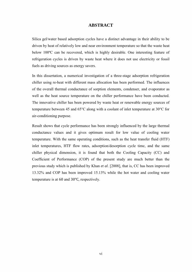
ABSTRACT
Silica gel/water based adsorption cycles have a distinct advantage in their ability to be
driven by heat of relatively low and near environment temperature so that the waste heat
below 100ºC can be recovered, which is highly desirable. One interesting feature of
refrigeration cycles is driven by waste heat where it does not use electricity or fossil
fuels as driving sources as energy savers.
In this dissertation, a numerical investigation of a three-stage adsorption refrigeration
chiller using re-heat with different mass allocation has been performed. The influences
of the overall thermal conductance of sorption elements, condenser, and evaporator as
well as the heat source temperature on the chiller performance have been conducted.
The innovative chiller has been powered by waste heat or renewable energy sources of
temperature between 45 and 65°C along with a coolant of inlet temperature at 30°C for
air-conditioning purpose.
Result shows that cycle performance has been strongly influenced by the large thermal
conductance values and it gives optimum result for low value of cooling water
temperature. With the same operating conditions, such as the heat transfer fluid (HTF)
inlet temperatures, HTF flow rates, adsorption/desorption cycle time, and the same
chiller physical dimension, it is found that both the Cooling Capacity (CC) and
Coefficient of Performance (COP) of the present study are much better than the
previous study which is published by Khan et al. [2008], that is, CC has been improved
13.32% and COP has been improved 15.13% while the hot water and cooling water
temperature is at and , respectively.
vii
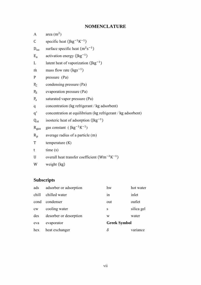
NOMENCLATURE
A area ( )
specific heat
surface specific heat
activation energy
L latent heat of vaporization
mass flow rate
pressure ( )
condensing pressure ( )
evaporation pressure ( )
saturated vapor pressure ( )
q concentration ( refrigerant / adsorbent)
concentration at equilibrium ( refrigerant / adsorbent)
isosteric heat of adsorption
gas constant ( )
average radius of a particle ( )
temperature ( )
time ( )
overall heat transfer coefficient
weight
Subscripts
ads adsorber or adsorption hw hot water
chill chilled water in inlet
cond condenser out outlet
cw cooling water s silica gel
des desorber or desorption w water
eva evaporator Greek Symbol
hex heat exchanger variance

viii
TABLE OF CONTENTS
BOARD OF EXAMINERS .................................................................................................... ii
DEDICATION .................................................................................................... iii
CANDIDATE’S DECLARATION .................................................................................................... iv
ACKNOWLEDGEMENT .................................................................................................... v
ABSTRACT .................................................................................................... vi
NOMENCLATURE .................................................................................................... vii
CHAPTER ONE Introduction
1.1 Introduction .................................................................................................................................... 1
1.2 Basic Principles of Adsorption ........................................................................................ 1-2
1.3 Adsorption Principles ............................................................................................................. 2-4
1.4 Classification and Types of Adsorbents ………………............................................ 4
1.4.1 Silica gel ……………………………………...................................................................... 4-5
1.4.2 Activated alumina ……………………………………................................................ 5
1.4.3 Zeolites ……………………………………......................................................................... 5
1.4.4 Calcium chloride ……………………………………................................................... 5-6
1.4.5 Activated carbon ……………………………………................................................... 6
1.4.6 Oxide …….………………………….................................................................................... 6
1.5 Refrigerants and Adsorbents ............................................................................................. 6-8
1.6 Steps of Adsorption Cycle ……………….......................................................................... 8
1.6.1 Adsorption process ………………………………………………..…........................ 8
1.6.2 Desorption process ...................................................................................................... 9
1.6.3 Cooling process ............................................................................................................. 9
1.7 Overview of Adsorption Cooling Systems ............................................................. 9-10
1.8 Background of the Study ...................................................................................................... 10-12
1.9 Objective of the Present Study ........................................................................................ 13
CHAPTER TWO Thermodynamics Analysis of Adsorption Cycles
2.1 Introduction ..................................................................................................................................... 14
2.2 Basic Adsorption Cycle ......................................................................................................... 14-15
2.3 Heat Recovery Adsorption Refrigeration Cycle ................................................. 15-16
2.4 Mass Recovery Adsorption Refrigeration Cycle ............................................... 16-17

ix
2.5 Thermal Wave Cycle .............................................................................................................. 17-18
2.6 Convective Thermal Wave Cycle ................................................................................. 19-20
2.7 Multi-Stage and Cascading Cycle ................................................................................. 20-22
2.8 Operating Principles of Multi-Stage Adsorption Chiller ............................. 22
2.8.1 Single-stage chiller without re-heat scheme ............................................ 22-25
2.8.2 Two-stage chiller without re-heat scheme ................................................ 26-29
2.8.3 Two-stage chiller with re-heat scheme ........................................................ 30-38
2.8.4 Three-stage chiller without re-heat scheme ............................................. 39-42
2.8.5 Three-stage chiller with re-heat scheme ..................................................... 43-60
CHAPTER THREE Mathematical and Numerical Modeling
3.1 Energy Balance for the Adsorber/Desorber ........................................................... 61
3.2 Energy Balance for the Evaporator .............................................................................. 62
3.3 Energy Balance for the Condenser ............................................................................... 62-63
3.4 Mass Balance ................................................................................................................................ 63
3.5 Adsorption Rate .......................................................................................................................... 63-64
3.6 Measurement of the System Performance .............................................................. 64
3.7 Baseline Parameters and Standard Operating Conditions .......................... 64-65
3.8 Solution Procedure (Finite difference technique) ............................................. 65-67
3.9 Methodology ................................................................................................................................. 68
CHAPTER FOUR Results and Discussion
4.1 Effect of Thermal Conductance of Adsorber on CC and COP ............... 69-70
4.2 Effect of Thermal Conductance of Condenser on CC and COP ............ 70-71
4.3 Effect of Thermal Conductance of Evaporator on CC and COP ........... 71-72
4.4 Effect of Thermal Conductance of Adsorber on CC and COP
Improvement .................................................................................................................................
72-73
4.5 Effect of Thermal Conductance of Condenser on CC and COP
Improvement ..................................................................................................................................
74-75
4.6 Effect of Thermal Conductance of Evaporator on CC and COP
Improvement .................................................................................................................................
75-76
4.7 Effect of Thermal Conductance on Chilled Water Outlet .......................... 77-78
4.8 Effect of Total Cycle Time on CC and COP ......................................................... 79-80
4.9 Effect of Mass Recovery Time on CC and COP …………………………..…. 80-81
x
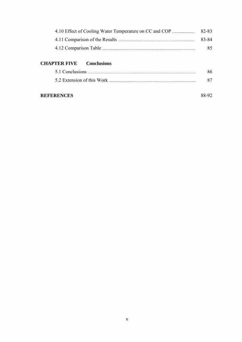
4.10 Effect of Cooling Water Temperature on CC and COP ........................... 82-83
4.11 Comparison of the Results .............................................................................................. 83-84
4.12 Comparison Table ................................................................................................................. 85
CHAPTER FIVE Conclusions
5.1 Conclusions ..................................................................................................................................... 86
5.2 Extension of this Work ............................................................................................................ 87
REFERENCES 88-92
xi
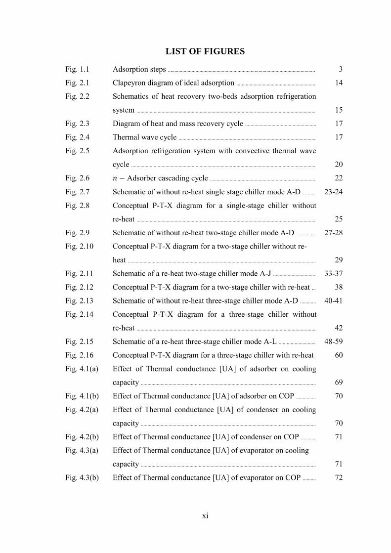
LIST OF FIGURES
Fig. 1.1 Adsorption steps ................................................................................................................ 3
Fig. 2.1 Clapeyron diagram of ideal adsorption ............................................................ 14
Fig. 2.2 Schematics of heat recovery two-beds adsorption refrigeration
system ........................................................................................................................................
15
Fig. 2.3 Diagram of heat and mass recovery cycle ...................................................... 17
Fig. 2.4 Thermal wave cycle ........................................................................................................ 17
Fig. 2.5 Adsorption refrigeration system with convective thermal wave
cycle ............................................................................................................................................
20
Fig. 2.6 Adsorber cascading cycle ................................................................................ 22
Fig. 2.7 Schematic of without re-heat single stage chiller mode A-D …...... 23-24
Fig. 2.8 Conceptual P-T-X diagram for a single-stage chiller without
re-heat ........................................................................................................................................
25
Fig. 2.9 Schematic of without re-heat two-stage chiller mode A-D ............... 27-28
Fig. 2.10 Conceptual P-T-X diagram for a two-stage chiller without re-
heat ...............................................................................................................................................
29
Fig. 2.11 Schematic of a re-heat two-stage chiller mode A-J ................................ 33-37
Fig. 2.12 Conceptual P-T-X diagram for a two-stage chiller with re-heat ... 38
Fig. 2.13 Schematic of without re-heat three-stage chiller mode A-D ............ 40-41
Fig. 2.14 Conceptual P-T-X diagram for a three-stage chiller without
re-heat .........................................................................................................................................
42
Fig. 2.15 Schematic of a re-heat three-stage chiller mode A-L ............................ 48-59
Fig. 2.16 Conceptual P-T-X diagram for a three-stage chiller with re-heat 60
Fig. 4.1(a) Effect of Thermal conductance [UA] of adsorber on cooling
capacity .....................................................................................................................................
69
Fig. 4.1(b) Effect of Thermal conductance [UA] of adsorber on COP ............... 70
Fig. 4.2(a) Effect of Thermal conductance [UA] of condenser on cooling
capacity .....................................................................................................................................
70
Fig. 4.2(b) Effect of Thermal conductance [UA] of condenser on COP ........... 71
Fig. 4.3(a) Effect of Thermal conductance [UA] of evaporator on cooling
capacity .....................................................................................................................................
71
Fig. 4.3(b) Effect of Thermal conductance [UA] of evaporator on COP .......... 72

xii
Fig. 4.4(a) Effect of Thermal conductance [UA] of adsorber on CC
improvement .........................................................................................................................
73
Fig. 4.4(b) Effect of Thermal conductance [UA] of adsorber on COP
improvement .........................................................................................................................
73
Fig. 4.5(a) Effect of Thermal conductance [UA] of condenser on CC
improvement .........................................................................................................................
74
Fig. 4.5(b) Effect of Thermal conductance [UA] of condenser on COP
improvement .........................................................................................................................
75
Fig. 4.6(a) Effect of Thermal conductance [UA] of evaporator on CC
improvement .........................................................................................................................
76
Fig. 4.6(b) Effect of Thermal conductance [UA] of evaporator on COP
improvement .........................................................................................................................
76
Fig. 4.7(a) Effect of Thermal conductance [UA] of adsorber on chilled
water outlet ............................................................................................................................
77
Fig. 4.7(b) Effect of Thermal conductance [UA] of evaporator on chilled
water outlet ............................................................................................................................
78
Fig. 4.7(c) Effect of Thermal conductance [UA] of condenser on chilled
water outlet ............................................................................................................................
78
Fig. 4.8(a) Effect of total cycle time on cooling capacity ........................................... 79
Fig. 4.8(b) Effect of total cycle time on COP ………………………………….................... 80
Fig. 4.9(a) Effect of mass recovery time on cooling capacity ................................... 81
Fig. 4.9(b) Effect of mass recovery time on COP ............................................................... 81
Fig. 4.10(a) Effect of cooling water temperature on cooling capacity ................... 82
Fig. 4.10(b) Effect of cooling water temperature on COP ............................................... 83
Fig. 4.11(a) Comparison of CC between the present study and Khan et al.
[2008] .........................................................................................................................................
84
Fig. 4.11(b) Comparison of COP between the present study and Khan et al.
[2008]..........................................................................................................................................
84

xiii
LIST OF TABLES
Table 2.1 Operational strategies of a single-stage adsorption chiller without
re-heat ................................................................................................................................................
25
Table 2.2 Operational strategies of a two-stage adsorption chiller without
re-heat ................................................................................................................................................
29
Table 2.3 Operational strategies of a two-stage adsorption chiller with
re-heat ................................................................................................................................................
38
Table 2.4 Operational strategies of a three-stage adsorption chiller without
re-heat ................................................................................................................................................
42
Table 2.5 Operational strategies of a three-stage adsorption chiller with
re-heat ................................................................................................................................................
60
Table 3.1 Baseline parameters ................................................................................................................. 64-65
Table 3.2 Standard operating conditions ......................................................................................... 65
Table 4.1 Table for comparison between the present study and previous study 85

CHAPTER ONE
Introduction
1.1 Introduction
Environment protection initiatives of international and environment agencies have led to
the intensification of research efforts of development of ozone and global warming safe
heat pump technology. A number of older, but not fully exploited, technologies are
being reassessed for refrigeration and heat pump application. These include absorption,
adsorption, thermoelectric and starling cycle. Along with a consideration for energy
efficiency, increasing attention is being given also to the use of waste heat and solar
energy. Absorption technologies using lithium bromide-water are fairly well developed
and have already been in use for many years but water-ammonia systems have
considerable scope for improvement and applications in many countries, e.g., Europe
including the United Kingdom. Adsorption technologies have been used extensively for
separation and purification of gases for the past few decades but their exploitation for
refrigeration and heating purposes is rather recent. This thesis is aimed at studying the
implications of silica gel/water as adsorbent and adsorbate pair.
1.2 Basic Principles of Adsorption
Adsorption occurs at the surface interface of two phases, in which cohesive forces
including electrostatic forces and hydrogen bonding act between the molecules of all
substances irrespective of their state of aggregation. Unbalanced surface forces at the
phase boundary cause changes in the concentration of molecules at the solid/fluid
interface. It aims to demonstrate the basic underlying principles of adsorption process.
Adsorption of water vapor on the surface of certain solids is important process from the
point of view of dehumidifying air for different uses such as air conditioning. The
process of adsorption involves separation of a substance from one phase accompanied
by its accumulation or concentration at the surface of another. The adsorbing phase is
the adsorbent, and the material concentrated or adsorbed at the surface of that phase is
the adsorb ate. During the adsorption process the first layer of water molecules binds
chemically on the surface of the solid desiccant material followed later by physical
absorption. A desiccant cycle consists of repeated adsorption and desorption of water
vapor from the desiccant material. Usually two air streams take part in this process; one

2
stream loses moisture to the desiccant material while the other removes that vapor due
to difference of vapor pressure. The basic desiccant cycle consists of three processes
namely desorption, cooling and adsorption processes. The adsorption and desorption
processes taking place in the desiccant, usually silica gel, coated matrix of a desiccant
wheel.
1.3 Adsorption Principles
Adsorption is selective binding of a substance by another solid substance; Barrer
[1978]. Almost all materials have the capacity to adsorb and hold water vapor but
commercial desiccants such as silica gel has significant capacity for holding the water.
These desiccants adsorb large amount of molecules into pores on their surface. This is
made possible by the fact that these pores have a large active surface area in the range
of 500 m2/g; Jokisch [1975]. Silica gel is a commonly used adsorbent, which is a
porous, amorphous form of silica (SiO2). Due to its unique internal structure silica gel is
radically different to other SiO2-based materials. It is composed of a vast network of
interconnected microscopic pores. Silica gel has great affinity for water vapors, and in
an unsaturated state it produces a very reduced partial pressure of 0.13 Pa; Willmes
[1992]. As a reference vapor pressure of water at a temperature of 32.88°C and a
relative humidity 60% is 3000 Pa. Adsorption of water vapor involves two distinct
processes which are:
• chemical adsorption (chemisorption) and
• physical adsorption
Chemical adsorption or chemisorption, the initial adsorption process, arises due to
binding of water molecules to hydroxyl group on the surface pores of silica gel;
Ruthven et al. [1984]. Chemical adsorption (chemisorption) occurs when covalent or
ionic bonds are formed between the adsorbing molecules and the solid substance. The
bonding forces of chemical adsorption are much greater than that of physical
adsorption. Thus, more heat is liberated. This bonding leads to change in the chemical
form of the adsorbed compounds and hence, it is irreversible. For this particular reason,
most of the adsorption processes applicable to the thermal system or cooling machine
mainly involve physical adsorption.

3
Physical adsorption which follows the chemisorption in additional layers is a reversible
process. Physical adsorption occurs when relatively weak intermolecular forces of
attraction called Van Der Waal forces hold water molecules on the pore surface of
adsorbent. It is physical adsorption which plays vital part in the adsorption of water
vapor in solid desiccant wheel. As against the absorption process where the molecules
of absorbate penetrate the volume of the absorbent, adsorption is a surface process in
which the adsorbed molecules do not diffuse into the lattice of the solid. The molecules
of adsorbed substance attach to or detach from the surface of the solid in a dynamic
process governed by vapor pressure difference between the adsorbent surface and
surrounding air. The molecules that collect on the surface form an interfacial layer that
has properties similar to the liquid phase of the adsorbed substance. The process of
adsorption is reversible for many substances.
Adsorption occurs in a series of three steps. In the first step, the contaminant is
transferred from the bulk gas stream to the external surface of the adsorbent material. In
the second step, the contaminant molecule diffuses from the relatively small area of the
external surface (a few square meters per gram) into the macrospores, transitional pores,
and microspores within each adsorbent. Most adsorption occurs in the microspores
because the majority of available surface area is there (hundreds of square meters per
gram). In the third step, the contaminant molecule adsorbs to the surface in the pore.
Fig. 1.1 illustrates this overall mass transfer, diffusion, and adsorption process.
Fig. 1.1: Adsorption steps

4
Steps 1 and 2 occur because of the concentration difference between the bulk gas stream
passing through the adsorbent and the gas near the surface of the adsorbent. Step 3 is the
actual physical bonding between the molecule and the adsorbent surface. This step
normally occurs more rapidly than steps 1 and 2.
1.4 Classification and Types of Adsorbents
During adsorption, the gas stream passes through a bed or layer of highly porous
material called the adsorbent. The compound or compounds to be removed, termed the
adsorbate(s), diffuse to the surface of the adsorbent and are retained because of weak
attractive forces, while the carrier gas passes through the bed without being adsorbed.
The adsorption capacity of an adsorbent is a function of the surface area of the pores in
its body. Generally, the internal surface area of pores is several orders of magnitude
larger than the outer surface area of the adsorbents. Consequently, the adsorbent can
adsorb huge quantities of adsorptive. Traditionally adsorbents are classified according
to the average diameter of their inner pores. The pore size determines the type of
substance that can be adsorbed. Three classes are given below:
Micro porous adsorbents 2 A° to 20 A°
Meso porous adsorbents 20 A° to 500 A°
Macro porous adsorbents > 500 A°
Where A° is the angstrom unit of length and is equal to one billionth of a meter,
m. Several types of adsorption materials are available. The most common types
of adsorbents for pollution control applications are describe bellow:
1.4.1 Silica gel
Silica gel is a granular, vitreous, porous form of silicon dioxide made synthetically from
sodium silicate. It is tough and hard. It is a naturally occurring mineral that is purified
and processed into either granular or beaded form. As a desiccant, it has an average pore
size of 2.4 nanometers and has a strong affinity for water molecules. Silica gel is most
commonly encountered in everyday life as beads in a small paper packet. In this form, it
is used as a desiccant to control local humidity in order to avoid spoilage or degradation
of some goods. In many items, moisture encourages the growth of mold and spoilage.
Condensation may also damage other items like electronics and may speed the
decomposition of chemicals, such as those in vitamin pills. Through the inclusion of
5
silica gel packets, these items can be preserved longer. Silica gel may also be used to
keep the relative humidity (RH) inside a high frequency radio or satellite transmission
system waveguide as low as possible. It is also used to dry the air in industrial
compressed air systems.
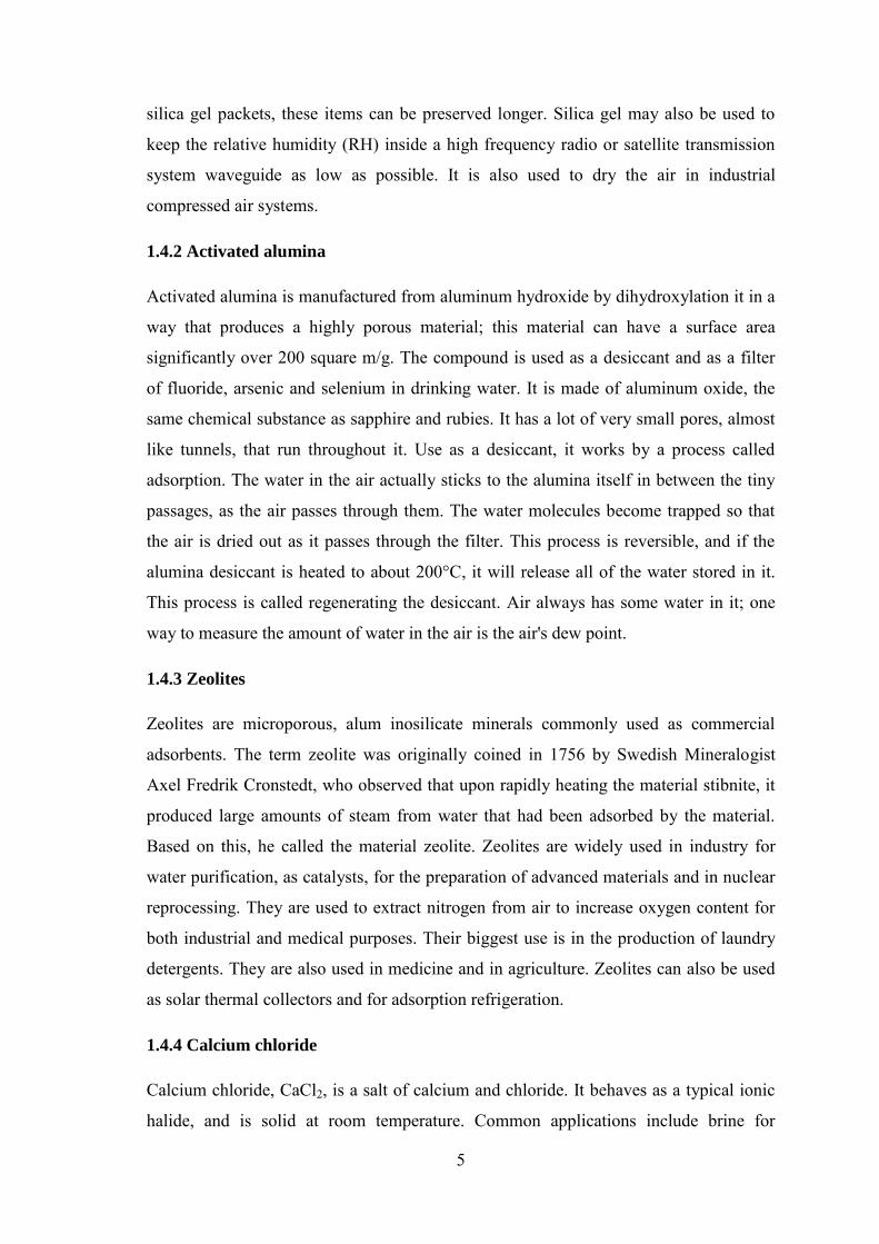
1.4.2 Activated alumina
Activated alumina is manufactured from aluminum hydroxide by dihydroxylation it in a
way that produces a highly porous material; this material can have a surface area
significantly over 200 square m/g. The compound is used as a desiccant and as a filter
of fluoride, arsenic and selenium in drinking water. It is made of aluminum oxide, the
same chemical substance as sapphire and rubies. It has a lot of very small pores, almost
like tunnels, that run throughout it. Use as a desiccant, it works by a process called
adsorption. The water in the air actually sticks to the alumina itself in between the tiny
passages, as the air passes through them. The water molecules become trapped so that
the air is dried out as it passes through the filter. This process is reversible, and if the
alumina desiccant is heated to about 200°C, it will release all of the water stored in it.
This process is called regenerating the desiccant. Air always has some water in it; one
way to measure the amount of water in the air is the air's dew point.
1.4.3 Zeolites
Zeolites are microporous, alum inosilicate minerals commonly used as commercial
adsorbents. The term zeolite was originally coined in 1756 by Swedish Mineralogist
Axel Fredrik Cronstedt, who observed that upon rapidly heating the material stibnite, it
produced large amounts of steam from water that had been adsorbed by the material.
Based on this, he called the material zeolite. Zeolites are widely used in industry for
water purification, as catalysts, for the preparation of advanced materials and in nuclear
reprocessing. They are used to extract nitrogen from air to increase oxygen content for
both industrial and medical purposes. Their biggest use is in the production of laundry
detergents. They are also used in medicine and in agriculture. Zeolites can also be used
as solar thermal collectors and for adsorption refrigeration.
1.4.4 Calcium chloride
Calcium chloride, CaCl2, is a salt of calcium and chloride. It behaves as a typical ionic
halide, and is solid at room temperature. Common applications include brine for

6
refrigeration plants, ice and dust control on roads, and desiccation. Because of its
hygroscopic nature, anhydrous calcium chloride must be kept in tightly sealed, air-tight
containers. Drying tubes are frequently packed with calcium chloride. Adding solid
calcium chloride to liquids can remove dissolved water.
1.4.5 Activated carbon
Activated carbon, also called activated charcoal, activated coal, or carbo activatus, is a
form of carbon processed to be riddled with small, low-volume pores that increase the
surface area available for adsorption or chemical reactions.
Due to its high degree of micro porosity, just one gram of activated carbon has a surface
area in excess of 500 m2, as determined by adsorption isotherms of carbon dioxide gas
at room or 0.0°C temperature. An activation level sufficient for useful application may
be attained solely from high surface area; however, further chemical treatment often
enhances adsorption properties.
Activated carbon is used in gas purification, decaffeination, gold purification, metal
extraction, water purification, medicine, sewage treatment, air filters in gas masks and
respirators, filters in compressed air and many other applications.
1.4.6 Oxide
An oxide is a chemical compound that contains at least one oxygen atom and one other
element in its chemical formula. Metal oxides typically contain an anion of oxygen in
the oxidation state of 2. Most of the Earth's crust consists of solid oxides, the result of
elements being oxidized by the oxygen in air or in water. Hydrocarbon combustion
affords the two principal carbon oxides: carbon monoxide and carbon dioxide. Even
materials considered pure elements often develop an oxide coating. For example,
aluminum foil develops a thin skin of Al2O3 that protects the foil from further corrosion.
1.5 Refrigerants and Adsorbents
There are several working pairs for solid adsorption. For the successful operation of a
solid adsorption system, careful selection of the working medium is essential. It is
because; the performance of the system varies over a wide range using different
working pairs at different temperatures. The advantages and disadvantages of different
working media and their properties are listed and discussed in this section. For any
7
refrigerating application, the adsorbent must have high adsorptive capacity at ambient
temperatures and low pressures but less adsorptive capacity at high temperatures and
high pressures. Thus, adsorbents are first characterized by surface properties such as
surface area and polarity. A large specific surface area is preferable for providing large
adsorption capacity, and hence an increase in internal surface area in a limited volume
inevitably gives rise to large number of small sized pores between adsorption surfaces.
The size of the microspores determines the effectiveness of absorptivity and therefore
distribution of microspores is yet another important property for characterizing
absorptivity of adsorbents. Based on the above discussion, the choice of the adsorbent
will depend mainly on the following factors:
• high adsorption and desorption capacity, to attain high cooling effect;
• good thermal conductivity, in order to shorten the cycle time;
• low specific heat capacity;
• chemically compatible with the chosen refrigerant;
• low cost and widely available.
The selected adsorbate (working fluid) must have most of the following desirable
thermodynamics and heat transfer properties:
• high latent heat per unit volume;
• molecular dimensions should be small enough to allow easy adsorption;
• high thermal conductivity;
• good thermal stability;
• low viscosity;
• low specific heat;
• non-toxic, non-inflammable, non-corrosive; and
• chemically stable in the working temperature range.
Based on the above criteria, some of the appropriate working pairs are zeolite-water,
zeolite-organic refrigerants, silica gel-water, zeolite-water and activated carbon-
methanol in solid adsorption systems. Several refrigeration applications have been
studied using various adsorbent and adsorbate pairs. The recent new development of
activated carbon fiber (ACF) shows the possibility for applications in adsorption
refrigeration. One good example is the development in Byelorussia of a refrigerator
prototype using ACF-ethanol and ACF-acetone pairs has been reported; Vasiliev et al.

8
[1996]. New experiments have also been shown by Vasiliev et al. [1995] to use a heat
pipe for heating/cooling ACF adsorbers for the ACF-NH3 pair.
In China, several studies had been carried out on solar powered refrigerators using
different adsorption pairs such as zeolite-water and activated carbon-methanol. A
theoretical analysis was carried out by Oertel and Fischer [1998] for a prediction of the
achievable COP using methanol/silica gel. Tamainot and Critoph [2000] investigated
the thermophysical properties of two types of monolithic activated carbons with an
intention to design and fabricate a high performance generator for sorption refrigeration
systems and heat pumps using ammonia as refrigerant. It was found that, reduction in
volume from granular bed to monolithic bed was up to 50% which could lead to
substantial economic gain.
1.6 Steps of Adsorption Cycle
The ability of sorption materials such as silica gel to attract and hold large quantities of
water on to its internal pore surface is used to dehumidify air. The process of
dehumidifying air with the help of desiccant materials is also called chemical
dehumidification. Chemical dehumidification is based on the migration of water vapor
from process air towards the surface of the desiccant due to the difference in partial
vapor pressure. The pressure gradient is orientated in the direction of desiccant because
it is dry and cool. Cargocaire [1982] and Pietro et al. [2005] give idea about the steps of
a typical cycle of the desiccant.
1.6.1 Adsorption process
Initially the adsorption material (desiccant material) is cool and dry. When air passes
through desiccant material adsorption process starts gradually the air becomes drier and
desiccant material experiences a rise in its water content. Eventually the desiccant
material reaching saturation state where it cannot hold any more vapor and the vapor
pressure of the desiccant surface becomes equal to surrounding air partial vapor
pressure and the migration of vapor to the desiccant ceases.

9
1.6.2 Desorption process
During desorption process vapor is removed from the adsorption material by exposing it
to hot regeneration fluid flow. As a result of this heating the gradient changes its
direction and the water vapor transfers from the desiccant to the air.
1.6.3 Cooling process
The material is cooled until the starting temperature is reached consequently the
humidity content and vapor pressure is restored; the cycle can now be repeated. It is
apparent from above description that desiccant cycle is run by the vapor pressure
difference between air and solid desiccant material. When the vapor pressure on
desiccant surface is low as compared to surrounding air then water vapor flows toward
it and is held by electrostatic forces this is adsorption. On the other hand, when air has a
lower vapor pressure due to high temperature or dryness then water vapor detach from
the solid desiccant surface and are removed by the flowing air in a process called
desorption. The regeneration or desorption can be obtained by using hot air or dry air.
1.7 Overview of Adsorption Cooling Systems
One way to decrease electricity demand due to cooling is to use environmentally
benign, thermally-powered cooling systems such as adsorption systems where the term
"adsorption" in this study refers to solid physical sorption, not chemical sorption.
Basically, in an adsorption cooling cycle (or heat pump), the mechanical compressor in
the well-known conventional vapor-compression air conditioners that is generally
powered by electricity is replaced with a thermal compressor that is driven by low grade
thermal energy like solar energy or waste heat, and they do not require electricity,
except for circulation pumps. Although adsorption cooling systems are not widely
available in the market, these systems are proposed as a promising technology that
deserves further research since Ziegler [2002], Sumathy et al. [2003] and Wang et al.
[2005] do not include rotating compressor parts.
Some of the advantages of adsorption cooling systems relative to conventional vapor-
compression systems can be listed as
Environmentally benign

10
Can be operated with low-grade thermal energy such as solar, geothermal and
waste heat
Thermal energy storage possible
Does not have moving parts, therefore long lifetime without noise and vibration
Simple control and maintenance
Nevertheless, there are also some disadvantages of adsorption cooling systems
compared with the conventional vapor-compression systems that can be listed as
according [2002-2003] as:
Low coefficient of performance
Intermittent (not continuous) cooling
System has to be operated under vacuum conditions and it is hard to maintain
this vacuum
Larger volume and weight
1.8 Background of the Study
The quest to accomplish a safe and comfortable environment has always been one of the
main preoccupations of the sustainability of human life. Widespread efforts are
currently underway to utilize available energy resources efficiently by minimizing waste
energy and develop replacements for the traditionally refrigerants (CFCs and HCFCs),
which contribute to ozone depletion and greenhouse warming. The environment-
friendly adsorption cooling system is an attractive alternative to the traditional CFC or
HCFC-based vapor-compression cooling system as it employs safe and natural
refrigerants. Another advantage of such adsorption cooling system is that they can be
driven by low-grade energy such as waste heat or solar energy. As a result, adsorption
cooling systems have attracted considerable attentions in recent years. Adsorption
cooling system is a noiseless, non-corrosive and environment-friendly energy
conversion system. So, many researchers around the world have made significant efforts
to study such a cooling system in order to commercialize it.
With the increasing trend in energy consumption and worldwide economic growth, the
general trend in cooling and air conditioning requirements of industry and buildings is
also increasing. To meet the demand in cooling, mechanical vapor-compression systems

11
are commonly used which can be classified as conventional systems; Dhar et al. [2001].
Most of the advanced cycles in adsorption refrigeration/heat pump are proposed to
achieve high Coefficient of Performance (COP) and/or Cooling Capacity (CC) values.
Few cycles, however, are proposed to utilize relatively low temperature heat source.
These systems are very popular due to their high coefficients of performance, small
sizes and low weights. However, they also exhibit some disadvantages such as
contributing to global warming and ozone layer depletion and high energy
consumptions. One of the disadvantages of conventional vapor-compression systems
can be stated that these systems include refrigerants such as chlorofluorocarbon (CFC),
hydro-chlorofluorocarbon (HCFC) or hydrofluorocarbons (HFC) which have high
global warming potential and ozone depletion potential by Calm [2002] and McMullan
[2002]. Since the global warming problem is presently more critical, researchers are
studying ways to reduce the emission of these greenhouse gases and overcome this
significant disadvantage of conventional cooling systems. Another main disadvantage of
conventional cooling systems is their large electricity consumption which causes a need
for new investments and new infrastructure, such as new power plants, transmission and
distribution lines on the electricity networks; Papadopoulos et al. [2003]. However,
adsorption cycles have some distinct advances over the other systems in viewpoints of
their ability to be driven by relatively low heat source temperature; Kashiwagi et al.
[2002].
Accordingly, during the last few decades’ research aimed at the development of
thermally powered adsorption cooling technologies has been intensified. The authors
offer double benefits of reductions in energy consumption, peak electrical demand in
tandem with adoption of environmentally benign adsorbent/ refrigerant pairs such as
zeolite/water by Karagiorgas and Meunier [1987], activated carbon/ ammonia by
Critoph and Vogel [1986], activated carbon/ methanol by Critoph [1989] and silica
gel/water by Boelman et al. [1995] without compromising the desired level of comfort
conditions. It is well known that the performance of adsorption cooling/ heating system
is lower than that other heat driven heating/ cooling systems specially, absorption
system provided that the available heat source temperature is at 75°C or higher. From
this context, many authors proposed and / or investigated the adsorption cooling and
heating system to improve the performance. Meunier [1986] investigated the system
performance of cascading cycle in which an active/methanol cycle is topped by

12
zeolite/water cycle. To improve the value of Coefficient of Performance (COP), Shelton
et al. [1990] proposed thermal wave regenerative adsorption heat pump. Pons and
Poyelle [1999] investigated the effect of mass recovery process in convectional two bed
adsorption cycle to improve the cooling power. Few cycles, however, are proposed to
utilize relatively low temperature heat source. To utilized low temperature waste heat
source between 40 and 60°C, Saha et al. [1995] proposed and examined experimentally
a three-stage adsorption chiller with silica gel/water pair. Saha et al. [2000] also
introduce a two-stage adsorption chiller and the required driving heat source
temperature is validated experimentally. In the two stage chiller, it is possible to get
effective cooling with driving heat source temperature bellow 60°C. A novel adsorption
chiller, namely, 're-heat two stage' chiller is introduced by: Alam et al. [2003] and he
has shown that the chiller is able to exploit the heat source of temperature between 50°C
and 90°C and can produce effective cooling. Khan et al. [2006] studied the effect of
thermal conductance and adsorbent mass on a two-stage adsorption chiller using re-heat
scheme. Later, Khan et al. [2008] investigated the performance evaluation of multi-
stage, multi-bed adsorption chiller employing re-heat scheme. Saha et al. [1997]
investigated the influence of the thermal conductance of sorption elements
(adsorber/desorber, evaporator and condenser) on the performance of a silica-gel-water
advanced adsorption chiller. They considered the thermal capacitance ratio of the
adsorbent and metal of the adsorber/desorber heat exchanger. Farid et al. [2011] studied
numerically the performance investigation of a silica gel/water based on two-stage,
four-bed adsorption chiller with different mass allocation. Recently, Sultana and Khan
[2014] investigated the effect of thermal conductance of evaporator on performance of a
two stage adsorption chiller (re-heat) with different mass allocation.
In the present study, the adsorption chiller has been investigated the effect of thermal
conductance on cooling capacity (CC), the co-efficient of performance (COP), chilled
water outlet and their improvement ratio by keeping the different mass ratio among the
upper, middle and lower beds (1:3:4 mass ratio) fixed.

13
1.9 Objectives of the Present Study
The primary objective of the study is to determine the effect of thermal conductivity
with different mass allocation on a re-heat three-stage adsorption chiller. To get the
optimum Cooling Capacity (CC) and Co-efficient of Performance (COP) of the chiller,
it has been investigated the following results:
To investigate the system performance, thermal conductance of the sorption
elements was varied by keeping the different mass ratio among the upper,
middle and lower beds (1:3:4 mass ratio) fixed.
To determine the influence of the thermal conductance on the calculated cooling
capacity.
To investigate the effect of thermal conductance on the calculated coefficient of
performance.
To determine the influence of the thermal conductance on the calculated
average chilled water outlet temperature.
To identify the effect of mass recovery time and total cycle time on system
performance.
CHAPTER TWO
Thermodynamics Analysis of Adsorption Cycles
2.1 Introduction
As a good opportunity to replace CFCs or HCFCs refrigeration, adsorption refrigeration
research has got enough attentions during the last few years, specially its potential
applications in waste heat recovery, solar energy utilization etc. The research extends
not only in refrigeration itself, but also to Thermodynamics, Chemical Engineering,
Material Science, New Energy, and specific technologies are involved. Adsorption
refrigeration with different cycles has been studied extensively by Wang [2001], and the
most important application of thermodynamics to adsorption is the calculation of phase
equilibrium between a gaseous mixture and a solid adsorbent. Some of the typical
adsorption refrigeration cycles are describing bellow:
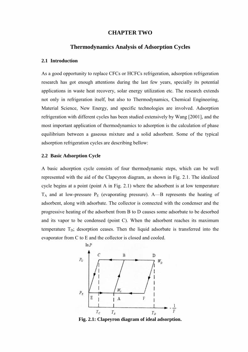
2.2 Basic Adsorption Cycle
A basic adsorption cycle consists of four thermodynamic steps, which can be well
represented with the aid of the Clapeyron diagram, as shown in Fig. 2.1. The idealized
cycle begins at a point (point A in Fig. 2.1) where the adsorbent is at low temperature
TA and at low-pressure PE (evaporating pressure). A—B represents the heating of
adsorbent, along with adsorbate. The collector is connected with the condenser and the
progressive heating of the adsorbent from B to D causes some adsorbate to be desorbed
and its vapor to be condensed (point C). When the adsorbent reaches its maximum
temperature TD; desorption ceases. Then the liquid adsorbate is transferred into the
evaporator from C to E and the collector is closed and cooled.
Fig. 2.1: Clapeyron diagram of ideal adsorption.

15
The decrease in temperature D to F induces the decrease in pressure from PC to PE. Then
the collector is connected to the evaporator and adsorption and evaporation occurs while
the adsorbent is cooled from F to A. During this cooling period heat is withdrawn to
decrease the temperature of the adsorbent.
2.3 Heat Recovery Adsorption Refrigeration Cycle
The semi-continuous heat recovery cycle is usually operated with two adsorption beds.
The adsorber to be cooled will transfer its heat to the adsorber to be heated, which
includes sensible heat as well as heat of adsorption. This heat recovery process will lead
to a higher system COP. Multi-beds could be also adopted to get more heat recovery
and thereby to attain higher COP, but the operation of a practical system will be
complicated. A quasi-continuous adsorption refrigeration system with heat recovery was
investigated by Wang et al. [2001] and the flow path is shown in Fig. 2.2. While
adsorber 1 is cooled and connected to the evaporator to realize adsorption refrigeration
in evaporator, the adsorber 2 connected to the condenser is heated to obtain heating-
desorption-condensation.
Fig. 2.2: Schematics of heat recovery two-beds adsorption refrigeration system.
The condensed refrigerant liquid flows into evaporator via a flow control valve. The
operation phase can be changed, and the go-between will be a short time heat recovery
process. Two pumps are used to drive the thermal fluid in the circuit between two
adsorbers (the connection to the heater and cooler are blocked during this process).
Jones [1991] suggested an improvement to the process by installing more than two
adsorbers into the system. The operating principle of the cycle remains the same, relying
on heat transfer flowing between the adsorbers and the desorbers. Comparing with the
basic cycle, heat recovery in this process is only effective if the heat transfer fluid

16
temperature leaving the adsorbers is sufficiently high. Simulation results have shown
that the maximum value of the COP depends on the number of adsorbers and desorbers
installed. The analysis was further extended to a system containing six adsorbers and six
desorbers at the same test temperature conditions (evaporation at 5°C and condensation
at 35°C).
2.4 Mass Recovery Adsorption Refrigeration Cycle
Apart from the above discussed heat recovery operation, it had been proved that mass
recovery is also very effective for heat recovery adsorption heat pump operation. In this
process, at the end of each half cycle, one adsorber is cold and the other one is hot.
Meanwhile, the former one which is at low pressure, must be pressurized up to the
condenser pressure, and similarly, the other one which is at high pressure must be
depressurized down to the evaporator pressure. With just one tube between the
adsorbers and a vapor valve, part of this pressurization—depressurization can be
achieved by transferring vapor from the latter adsorber to the former one. This process
can also be called as an ‘internal vapor recovery process, and is reported to enhance the
cooling power of the unit without reducing the COP by more than 10%.
The above explained process involves only mass transfer and hence the process is rapid.
To obtain a 'double effect', mass recovery could be initiated followed by heat recovery.
An ideal heat and mass recovery cycle is shown in Fig. 2.3, in which the heat recovery
state for a two bed system is shown by the state points e - e'. The mass recovery cycle
(
) is an extended form of a two bed basic cycle
or two bed heat recovery cycle shown in Fig. 2.3, and the
cycled mass is increased from to ; which causes the refrigeration effect to
increase. The principle of these cycles can be described using Fig. 2.3. The very first
part of each half cycle is the mass recovery process (path and ). Then
the heat recovery process proceeds: heat is transferred from the hot adsorber to the cold
one (path ). As a consequence, the hot adsorber is first depressurized (path
), it then adsorbs vapor from the evaporator (path). Meanwhile, the cold
adsorber is first pressurized (path ), and then vapor that is desorbed passes into
the condenser (path ). Theoretically, the heat recovery process develops until the
adsorbers reach the same temperature. Actually, there still remains a temperature
difference between the adsorbers at the end of this period. Then, for closing each half

17
cycle, the adsorbers are, respectively, connected to the heat source and heat sink (path
and ). The second half-cycle is performed the same way except that the
adsorbers now exchange their roles. Due to this process, about 35% of the total energy
transmitted to each adsorber can be internally recovered, including part of the latent heat
of sorption.
Fig. 2.3: Diagram of heat and mass recovery cycle.
2.5 Thermal Wave Cycle
To further improve the heat regenerative ratio, Shelton and Wepfer [1990] had proposed
an attractive cycle called 'thermal wave cycle'. In this process, it is assumed that a large
temperature gradient exists along an adsorption
bed. Heating and cooling of the adsorbent beds is
achieved via a heat transfer fluid such as high
temperature oil. The system consists of two
adsorber beds and two heat exchangers connected
in series (Fig. 2.4) to effect semi continuous
process. The function of the bed and heat
exchanger is to combine a large area of heat
transfer surface with a low oil flow rate. A typical
thermal wave cycle is shown in Fig. 2.4. The
cycle consists of two phases: In the first phase,
the oil recovers heat from bed 2 (hot), has a
further heat addition from the heat exchanger and
Fig. 2.4: Thermal wave cycle.

18
then proceeds to heat bed 1 (cold). As the heating of the bed proceeds, bed 1 desorbs
refrigerant which passes to the condenser (giving a useful heat output in the case of a
heat pump) and bed 2 adsorbs gas from the evaporator which provides cooling. In the
following phase (second phase) of the cycle the pump is reversed, and hence, bed 1 is
cooled (adsorbing) and bed 2 is heated (desorbing) in a similar fashion until the original
conditions are reached and the pump can again be reversed. Though the procedure is
simple, significant heat recovery can be achieved. Further, the system would achieve
much better performance due to the combination of the special nature of the internal bed
heat exchangers and the low flow rate. Although many researchers have studied the
cycle, up to now, there is no report of a successful prototype adopting thermal wave
cycle. Also, some experimental reports had shown that the performance of the thermal
wave cycle is not very good. The efficiency of the thermal wave regenerative system
depends on a relatively large number of parameters: for example, rates of various heat
transfer processes, the flow rate of the circulating fluid, the cycle time, the adsorber
configuration, etc. A numerical analysis of adsorptive heat pumps with thermal wave
heat regeneration had been presented by Sun et al. [1997]. They had derived two time
constants which can be used directly to quantify the relative importance of the two heat
transfer processes. This allows ready determination of which of the two processes is rate
limiting and needs to be improved. The work has also confirmed that the performance of
an adsorptive heat pump system using a traditional packed-bed would be too low, even
with heat regeneration, and therefore a significant enhancement of heat transfer
properties inside the adsorber is necessary.
Similar to the above numerical study, the effect of various operating parameters on the
performance of an adsorptive thermal wave regenerative heat pump had been studied by
Ben Amar et al. [1996], theoretically. They had developed a two-dimensional model
which simultaneously considers heat and mass transfer in the bed. The results have
shown that under ideal conditions, the performance of a thermal wave regenerative heat
pump is considerably better than that of a basic 'uniform temperature' heat pump. The
study showed that a COP greater than 1 and a power of cold production of near 200 W
per kg of adsorbent could be obtained. For air-conditioning applications, these figures
are slightly higher than those obtained with other single-stage solid-gas systems as
chemical heat pumps; Spinner [1993].
19
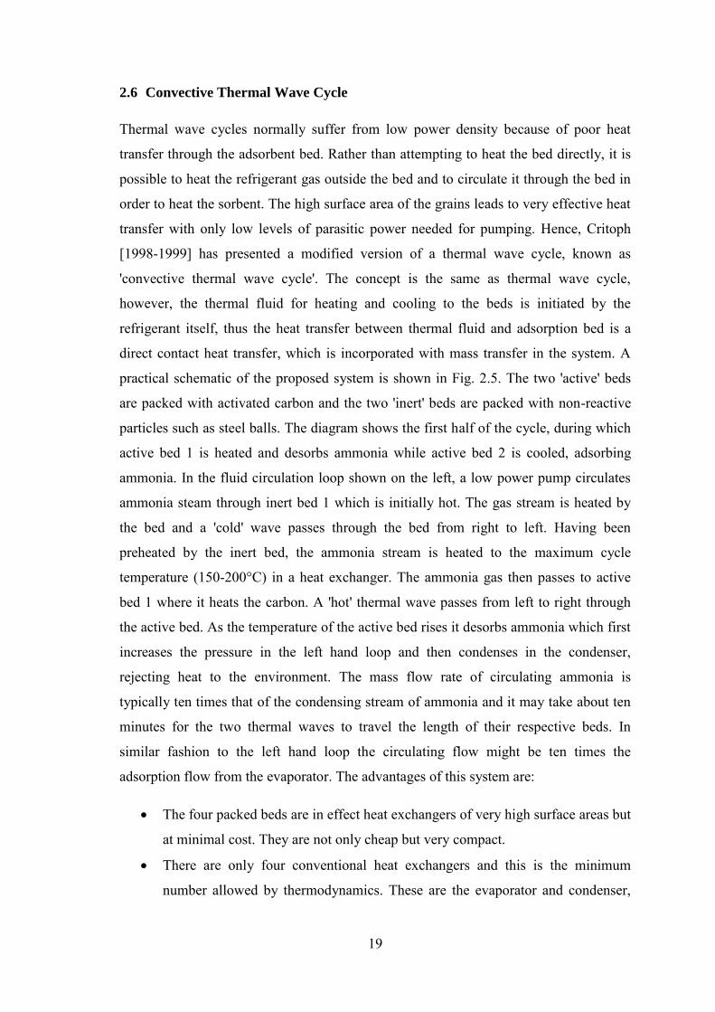
2.6 Convective Thermal Wave Cycle
Thermal wave cycles normally suffer from low power density because of poor heat
transfer through the adsorbent bed. Rather than attempting to heat the bed directly, it is
possible to heat the refrigerant gas outside the bed and to circulate it through the bed in
order to heat the sorbent. The high surface area of the grains leads to very effective heat
transfer with only low levels of parasitic power needed for pumping. Hence, Critoph
[1998-1999] has presented a modified version of a thermal wave cycle, known as
'convective thermal wave cycle'. The concept is the same as thermal wave cycle,
however, the thermal fluid for heating and cooling to the beds is initiated by the
refrigerant itself, thus the heat transfer between thermal fluid and adsorption bed is a
direct contact heat transfer, which is incorporated with mass transfer in the system. A
practical schematic of the proposed system is shown in Fig. 2.5. The two 'active' beds
are packed with activated carbon and the two 'inert' beds are packed with non-reactive
particles such as steel balls. The diagram shows the first half of the cycle, during which
active bed 1 is heated and desorbs ammonia while active bed 2 is cooled, adsorbing
ammonia. In the fluid circulation loop shown on the left, a low power pump circulates
ammonia steam through inert bed 1 which is initially hot. The gas stream is heated by
the bed and a 'cold' wave passes through the bed from right to left. Having been
preheated by the inert bed, the ammonia stream is heated to the maximum cycle
temperature (150-200°C) in a heat exchanger. The ammonia gas then passes to active
bed 1 where it heats the carbon. A 'hot' thermal wave passes from left to right through
the active bed. As the temperature of the active bed rises it desorbs ammonia which first
increases the pressure in the left hand loop and then condenses in the condenser,
rejecting heat to the environment. The mass flow rate of circulating ammonia is
typically ten times that of the condensing stream of ammonia and it may take about ten
minutes for the two thermal waves to travel the length of their respective beds. In
similar fashion to the left hand loop the circulating flow might be ten times the
adsorption flow from the evaporator. The advantages of this system are:
The four packed beds are in effect heat exchangers of very high surface areas but
at minimal cost. They are not only cheap but very compact.
There are only four conventional heat exchangers and this is the minimum
number allowed by thermodynamics. These are the evaporator and condenser,

20
a gas heater whereby high-grade heat is input and a gas cooler whereby the low
grade heat of adsorption is rejected to the environment.
The cycle is highly regenerative since the packed beds act like large counter
flow heat exchangers. This results in good energy efficiency (i.e. high COP).
Fig. 2.5: Adsorption refrigeration system with convective thermal wave cycle.
2.7 Multi-Stage and Cascading Cycle
The adsorption cycles discussed in previous sections are applicable only to a single
stage cycle. The single stage cycle systems have certain limitations, that is, they cannot
effectively utilize high temperature heat source, as well as do not perform well at very
low temperatures. Hence, to improve the system performance under such situations,
adsorptive processes may be adapted for advanced cycles, such as, multi-stage and
cascading cycle. The basic idea of a multi-stage cycle is to perform the desorption-
condensation processes and evaporation- adsorption processes at different
temperature/pressure levels by using the 'same working pair'. The internal re-use of heat
of condensation or adsorption can increase the system performance significantly.
Another practical cycle that can make good use of high temperature heat source is the
'cascading cycle', which operates with 'different working pairs' (either liquid/liquid or
solid/liquid), such as zeolite- water/activated carbon-methanol, or zeolite-water/silica

21
gel-water, etc. These cascading cycles are applied to situations especially, when there
exists a large temperature difference between the heat source/ambient and the
temperature in the evaporator/refrigeration space. For such situations, it may not be
practical to use single stage cycle. Hence, one way of dealing with such situations is to
perform the evaporation/refrigeration process in stages, that is, to have two or more
cycles that operate in series at different temperature levels (cascading). A high
temperature heat source (e.g. boiler) is used to drive the high temperature stage
adsorption refrigeration cycle. The low temperature stage adsorption refrigeration is
driven by sensible heat and heat of adsorption obtained from high temperature stage. To
minimize the contribution of sensible heat, special care has been attached to the heat
management of the adsorbers; n-adsorber cycles operating with a single evaporator and
a single condenser have been proposed with sequences of heat recovery between
adsorbers. Such cycles offer some advantages: for example, a single condenser is used
and pressure in the n-adsorber unit is not higher than that in the unit operating an
intermittent cycle; moreover, adsorption heat at high temperature is used as desorption
heat at low temperature. Counteracting heat transfer fluid circuits between adsorbers
reduces entropy generation in comparison with what happens in intermittent cycles. The
driving heat supplied to the cycle is at high temperature level (Fig. 2.6) so that the
entropy generation—due to the in adaptation between the temperature levels of the
source and of the adsorber is much less in an n-adsorber cycle than in an intermittent
cycle. The same thing happens for the rejected heat: the rejection temperature is much
closer from the utility temperature with an n-adsorber cycle than with an intermittent
cycle. Very similar conclusions to that drawn by Scharfe et al. [1986] have been
presented by Meunier [1985] in the case of heat recovery between adsorbers. In a
particular case, Meunier has shown that using an infinite number of adsorbers with ideal
heat recovery between adsorbers, the maximum achievable—with given conditions of
operating temperatures would be a cooling COP equal to 1.85 corresponding to 68% of
ideal Carnot COP. Another cascading cycle which includes a triple effect machine
operating a cascade between a water zeolite heat pump and LiBr– H2O refrigerator has
been tested by Ziegler et al. [1985]. A lot of theoretical studies exists on the possibilities
of cascading cycles while few experimental data are available.

22
Fig. 2.6: n-Adsorber cascading cycle.
2.8 Operating Principles of Multi-Stage Adsorption Chiller
Different types of adsorption chiller with their operating principles are described in this
study. The main goal is to work with multi-stage adsorption chiller with re-heat using
silica gel/ water as adsorbent-adsorbate pair.
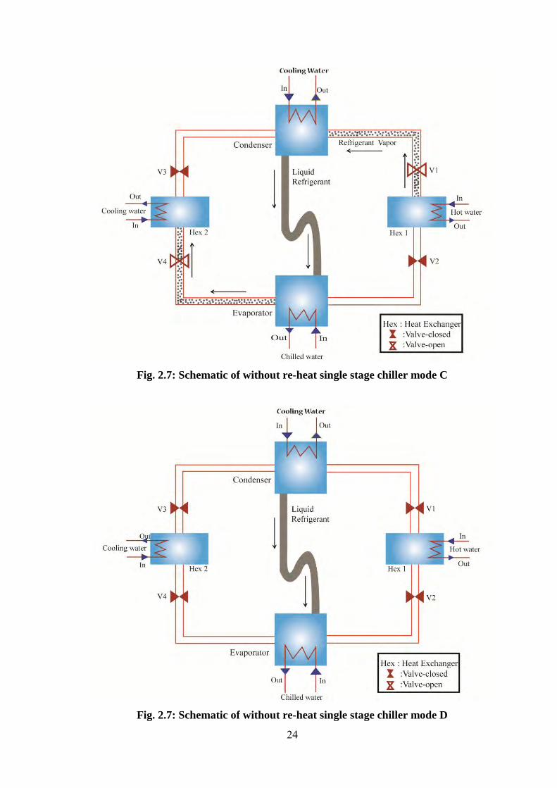
2.8.1 Single-stage chiller without re-heat scheme
A single stage adsorption chiller consists of four heat exchangers, namely, a condenser,
an evaporator and one pair adsorbent bed and metallic tubes for heat transfer fluid and
refrigerant flows as shown in Fig. 2.7. In an adsorption refrigeration system, adsorbent
beds are operated in a cycle through the four thermodynamic states, namely, pre-
heating, desorption, pre-cooling and adsorption period. The chiller can be operated in
different strategies, only one strategy has been described in the present study; the chiller
has four modes, A, B, C, D (Table 2.1). To describe the cycle of the system mode A, it
is assumed that Hex1-Evaporator is in adsorption process while Hex2 — Condenser is
in desorption process. In mode B, all valves are closed. Hex1 is heated by hot water, this
is called pre-heating position and Hex2 is cooled down by cooling water, this is called
pre-cooling position. These positions are happened only for a short intermediate period
of time (30 s for this system). In this process no adsorption/desorption occurs. After this
short period of time, valves V1 and V4 are opened to allow refrigerant to flow from
Hex1 to condenser, from evaporator to Hex2 (mode C). In mode D, all valves are closed
and Hex1 is in pre-cooling and Hex2 is in pre-heating position respectively.

23
Fig. 2.7: Schematic of without re-heat single stage chiller mode A
Fig. 2.7: Schematic of without re-heat single stage chiller mode B
24
Fig. 2.7: Schematic of without re-heat single stage chiller mode C
Fig. 2.7: Schematic of without re-heat single stage chiller mode D

25
Fig. 2.8: Conceptual P-T-X diagram for a single-stage chiller without re-heat
Table 2.1: Operational strategies of a single-stage adsorption chiller without re-heat
26
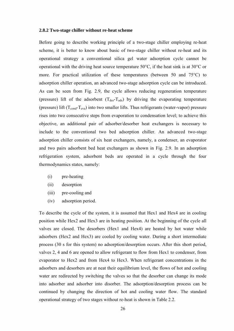
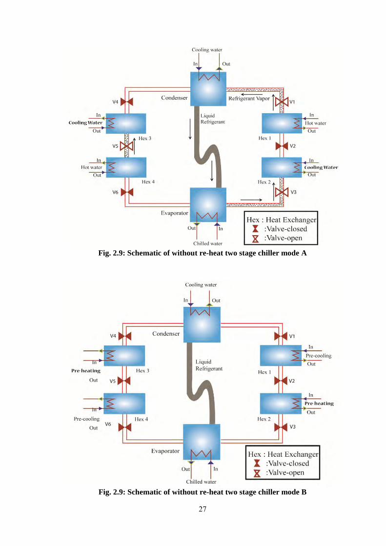
2.8.2 Two-stage chiller without re-heat scheme
Before going to describe working principle of a two-stage chiller employing re-heat
scheme, it is better to know about basic of two-stage chiller without re-heat and its
operational strategy a conventional silica gel water adsorption cycle cannot be
operational with the driving heat source temperature 50°C, if the heat sink is at 30°C or
more. For practical utilization of these temperatures (between 50 and 75°C) to
adsorption chiller operation, an advanced two-stage adsorption cycle can be introduced.
As can be seen from Fig. 2.9, the cycle allows reducing regeneration temperature
(pressure) lift of the adsorbent (Tdes-Tads) by driving the evaporating temperature
(pressure) lift (Tcond-Teva) into two smaller lifts. Thus refrigerants (water-vapor) pressure
rises into two consecutive steps from evaporation to condensation level; to achieve this
objective, an additional pair of adsorber/desorber heat exchangers is necessary to
include to the conventional two bed adsorption chiller. An advanced two-stage
adsorption chiller consists of six heat exchangers, namely, a condenser, an evaporator
and two pairs adsorbent bed heat exchangers as shown in Fig. 2.9. In an adsorption
refrigeration system, adsorbent beds are operated in a cycle through the four
thermodynamics states, namely:
(i) pre-heating
(ii) desorption
(iii) pre-cooling and
(iv) adsorption period.
To describe the cycle of the system, it is assumed that Hex1 and Hex4 are in cooling
position while Hex2 and Hex3 are in heating position. At the beginning of the cycle all
valves are closed. The desorbers (Hex1 and Hex4) are heated by hot water while
adsorbers (Hex2 and Hex3) are cooled by cooling water. During a short intermediate
process (30 s for this system) no adsorption/desorption occurs. After this short period,
valves 2, 4 and 6 are opened to allow refrigerant to flow from Hex1 to condenser, from
evaporator to Hex2 and from Hex4 to Hex3. When refrigerant concentrations in the
adsorbers and desorbers are at neat their equilibrium level, the flows of hot and cooling
water are redirected by switching the valves so that the desorber can change its mode
into adsorber and adsorber into disorber. The adsorption/desorption process can be
continued by changing the direction of hot and cooling water flow. The standard
operational strategy of two stages without re-heat is shown in Table 2.2.
27
Fig. 2.9: Schematic of without re-heat two stage chiller mode A
Fig. 2.9: Schematic of without re-heat two stage chiller mode B

28
Fig. 2.9: Schematic of without re-heat two stage chiller mode C
Fig. 2.9: Schematic of without re-heat two stage chiller mode D
29
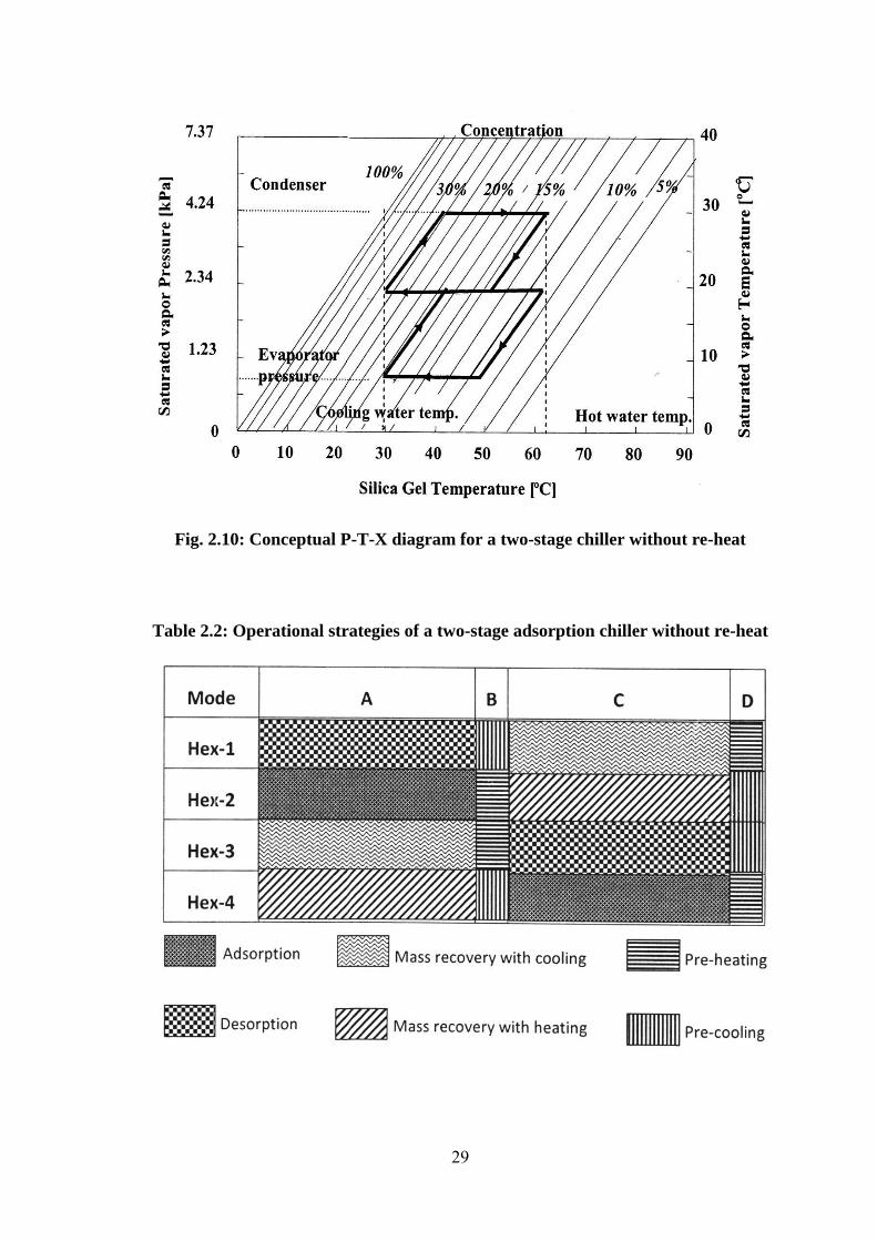
Fig. 2.10: Conceptual P-T-X diagram for a two-stage chiller without re-heat
Table 2.2: Operational strategies of a two-stage adsorption chiller without re-heat

30
2.8.3 Two-stage chiller with re-heat scheme
The design criteria of the two-stage adsorption chiller using re-heat is almost similar to
that of a two-stage adsorption chiller without re-heat which is developed by Alam et al.
[2003]. Operational strategy of a conventional two-stage chiller with re-heat scheme
(Table 2.3), however, is completely different from operational strategy of a
conventional two-stage chiller without re-heat scheme (Table 2.2). In two-stage
adsorption chiller, the evaporating pressure lift is divided into two consecutive pressure
lifts to exploit low heat source temperature by introducing four adsorbent beds. In the
two-stage adsorption chiller using re-heat, the evaporating pressure (temperature) lift
(Fig. 2.12), however, can be divided into different ways from the conventional two-
stage chiller (Fig. 2.10). If one bed is in the end position of adsorption-evaporation
process (Fig. 2.12) and another bed is in the end position of desorption-condensation
process (Fig. 2.12), those two beds can be connected with each other by continuing
cooling and heating and that can be done in the two bed conventional adsorption chiller
which is known as the mass recovery process presented by Akahira et al. [2005]. In this
time, another two beds are connected with condenser and evaporator to continue cooling
effects to complete one full cycle in re-heat scheme, all adsorbent beds pass through six
consecutive steps:
(i) desorption
(ii) mass recovery process with heating
(iii) pre-cooling
(iv) adsorption
(v) mass recovery process with cooling
(vi) pre-heating.
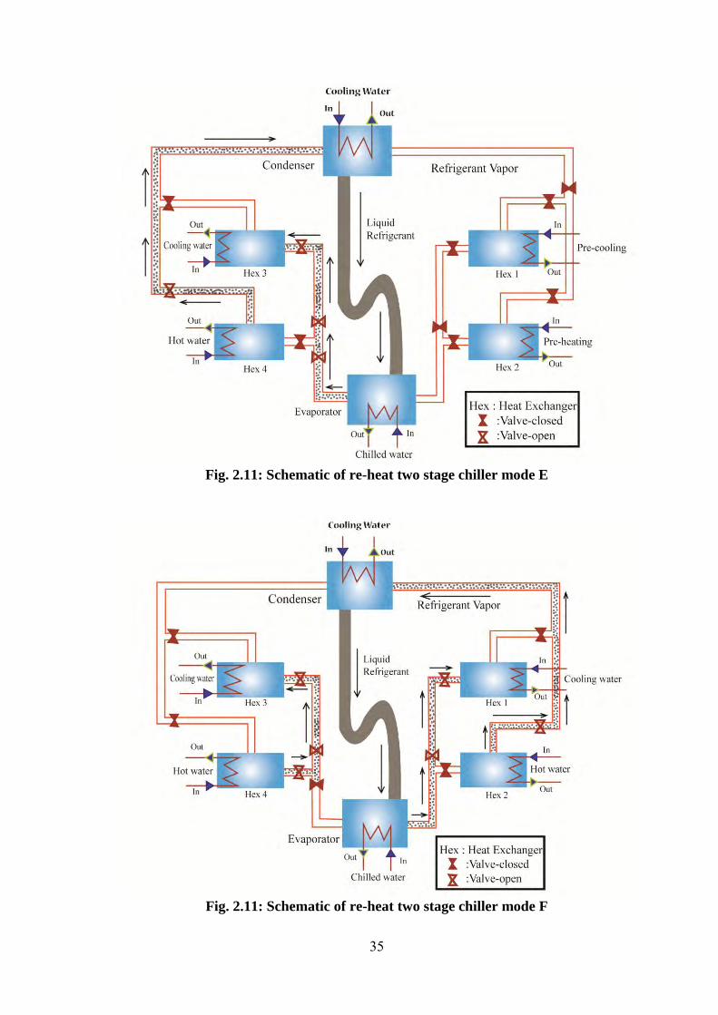
The two-stage adsorption chiller using re-heat comprises with four adsorbent beds, one
condenser, one evaporator, and metallic tubes for hot, cooling and chilled water flows as
shown in Fig. 2.11. In a conventional two stage chiller, lower two beds never interact
with the condenser and upper two beds never interact with the evaporator. However, in
the two- stage adsorption chiller using re-heat, all beds undergo through all process and
interact with the condenser and evaporator. The chiller can be operated in different
strategies. The chiller has 10 modes, mode-A, B, C, D, E, F, G, H, I and J (Table 2.3).
Mode A, B, C and eva-Hex2 is in adsorption process and cond-Hex1 is in desorption

31
process. In the adsorption-evaporation process, refrigerant (water) in evaporator is
evaporated at evaporation temperature, Teva and seized heat, Qeva from the chilled water.
The evaporated vapor is absorbed by adsorbent (silica gel), at which cooling water
removes the adsorption heat, Qads. The desorber (Hex1) is heated up to the temperature
(Tdes) by heat Qdes, provided by the driving heat source. The resulting refrigerant is
cooled down by temperature (Tcond) in the condenser by the cooling water, which
removes heat, Qcond. In Mode A, adsorber (Hex4) is connected with desorber (Hex3)
through pipe with continuing cooling water in Hex4 and hot water in Hex3. It is noted
that, at the beginning of mode A, Hex4 was in the end position of evaporation-
adsorption process and Hex3 was in the end position of desorption-condensation
process. Due to higher pressure difference at Hex3 and Hex4 in mode A, the refrigerant
mass circulation will be higher than that of conventional two stages. This will lead the
chiller to provide better performance. In mode B, adsorber (Hex4) is heated up by hot
water and the desorber (Hex3) is cooled down by cooling water. Mode B is warm up
process for Hex4 and Hex3.
When the pressure of adsorber (Hex3) and desorber (Hex4) are nearly equal to the
pressure of evaporator and condenser respectively, then Hex3 and Hex4 are connected
to evaporator and condenser respectively to flow the refrigerant.
This mode is denoted as mode C. In mode C, Hex4 works as desorber and hex3 works
as adsorber and this process will be continuing up to mode E. In Mode D, Hex2 is at the
end position of adsorption-evaporation process and Hex1 is at the end position of
desorption-condensation process. And are connected worth each other continuing
cooling water and hot water respectively.
When the pressure (temperature) of both Hex1 and Hex2 are nearly equal, the warm up
process will start, called mode E. In Mode E, Hex2 is heated up by hot water, and
cooling water cools down the Hex1. When the pressure of Hex1 and Hex2 are nearly
equal to the pressure of evaporator and condenser respectively, then Hex1 and Hex2 are
connected to evaporator and condenser respectively to flow the refrigerant. This
connection will continue up to mode F, G and H for Hex1 and Hex2. In mode F, Hex3
(at the end position of adsorption-evaporation process) and Hex4 is at the end position
of desorption-condensation process) are connected worth each other continuing cooling
water and hot water respectively. When the pressure (temperature) of both Hex3 and

32
Hex4 are nearly equal, the warm up process will start, called mode G. In Mode G, Hex3
is heated up by hot water, and cooling water cools down the Hex4. When the pressure of
Hex3 and Hex4 are nearly equal to the pressure of evaporator and condenser
respectively, then Hex3 and Hex4 are connected to evaporator and condenser
respectively to flow the refrigerant. This connection will continue up to mode H, I and J
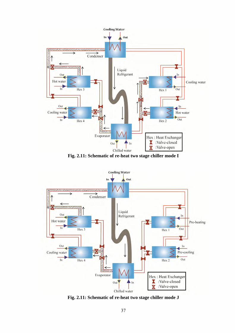
for Hex3 and Hex4. In mode I, Hex1 (at the end position of adsorption-evaporation
process) and Hex2 is at the end position of desorption-condensation process) are
connected worth each other continuing cooling water and hot water respectively. When
the pressure (temperature) of both Hex1 and Hex2 are nearly equal, the warm up
process will start, called mode J. In Mode J, Hex1 is heated up by hot water, and
cooling water cools down the Hex2. The mode J is the last process and after this mode,
all return to mode A (Table 2.3).

33
Fig. 2.11: Schematic of re-heat two stage chiller mode A
Fig. 2.11: Schematic of re-heat two stage chiller mode B

34
Fig. 2.11: Schematic of re-heat two stage chiller mode C
Fig. 2.11: Schematic of re-heat two stage chiller mode D
35
Fig. 2.11: Schematic of re-heat two stage chiller mode E
Fig. 2.11: Schematic of re-heat two stage chiller mode F

36
Fig. 2.11: Schematic of re-heat two stage chiller mode G
Fig. 2.11: Schematic of re-heat two stage chiller mode H
37
Fig. 2.11: Schematic of re-heat two stage chiller mode I
Fig. 2.11: Schematic of re-heat two stage chiller mode J

38
Fig. 2.12: Conceptual P-T-X diagram for a two-stage chiller with re-heat
Table 2.3: Operational strategies of a two-stage adsorption chiller with re-heat

39
2.8.4 Three-stage chiller without re-heat scheme
Most of the advanced cycles in adsorption refrigeration/heat pump are proposed to
achieve high COP and /or SCP values. Few cycles, however, are proposed to utilize
relatively low temperature waste heat sources. Three-stage advanced adsorption cycle is
the cycle that can use low-temperature heat source with a fixed near-
environmental temperature heat sinks . If chilled water at is to be obtained
with conventional adsorbent/refrigerant pair such as silica/gel water, a conventional
single-stage cycle will not be operational with such a low - temperature waste heat (Fig.
2.14). The reason is that the regenerating temperature lift of 15-30K is too small for an
evaporating temperature lift of 23K to be spanned by raising the pressure in one single-
stage. In order to overcome the technical difficulty intrinsic in operating a refrigeration
cycle, with such a small regenerating temperature lift, a three-stage adsorption cycle
without re-heat scheme is proposed and designed by Saha et al. [1995]. In the three-
stage adsorption cycle without re-heat scheme, the generating temperature lift of the
adsorbent can be small because the refrigerant evaporating temperature (or pressure) lift
is split into three smaller temperature lifts (Fig. 2.14). Pressure thus rises into three
progressive steps from evaporation to condensation level. To achieve this, the
introduction of two additional pairs of adsorbent beds is necessary (Fig. 2.13).
To describe the cycle of the system, it is assumed that Hex1, Hex4 and Hex5 are in
cooling position at temperature while Hex2, Hex3 and Hex6 are in heating position at
temperature [Fig. 2.13]. At the beginning of the cycle all valves are closed. The
desorbers (Hex2, Hex3 and Hex6) are heated by hot water while adsorbers (Hex1, Hex4
and Hex5) cooled by cooling water. During a short intermediate process (30 s for the
present system) no adsorption/desorption occurs. After this short period, valves V1, V3,
V6 and V8 are opened to allow refrigerant to flow from Hex2 to condenser, Hex6 to
Hex4, Hex3 to Hex1 and from evaporator to Hex5. When refrigerant concentrations in
the adsorbers and desorbers are near their equilibrium level, the flows of hot and cooling
water redirected by switching the valves so that the desorber can change its mode into
adsorber, and adsorber into desorber. The adsorption/desorpton process can be
continued by changing the direction of hot and cooling water flow. The standard
operational strategy (without re-heat scheme) is shown by Table 2.4.

40
Fig. 2.13: Schematic of without re-heat three stage chiller mode A
Fig. 2.13: Schematic of without re-heat three stage chiller mode B

41
Fig. 2.13: Schematic of without re-heat three stage chiller mode C
Fig. 2.13: Schematic of without re-heat three stage chiller mode D

42
Fig. 2.14: Conceptual P-T-X diagram for a three-stage chiller without re-heat.
Table 2.4: Operational strategies of a three-stage adsorption chiller without re-heat.
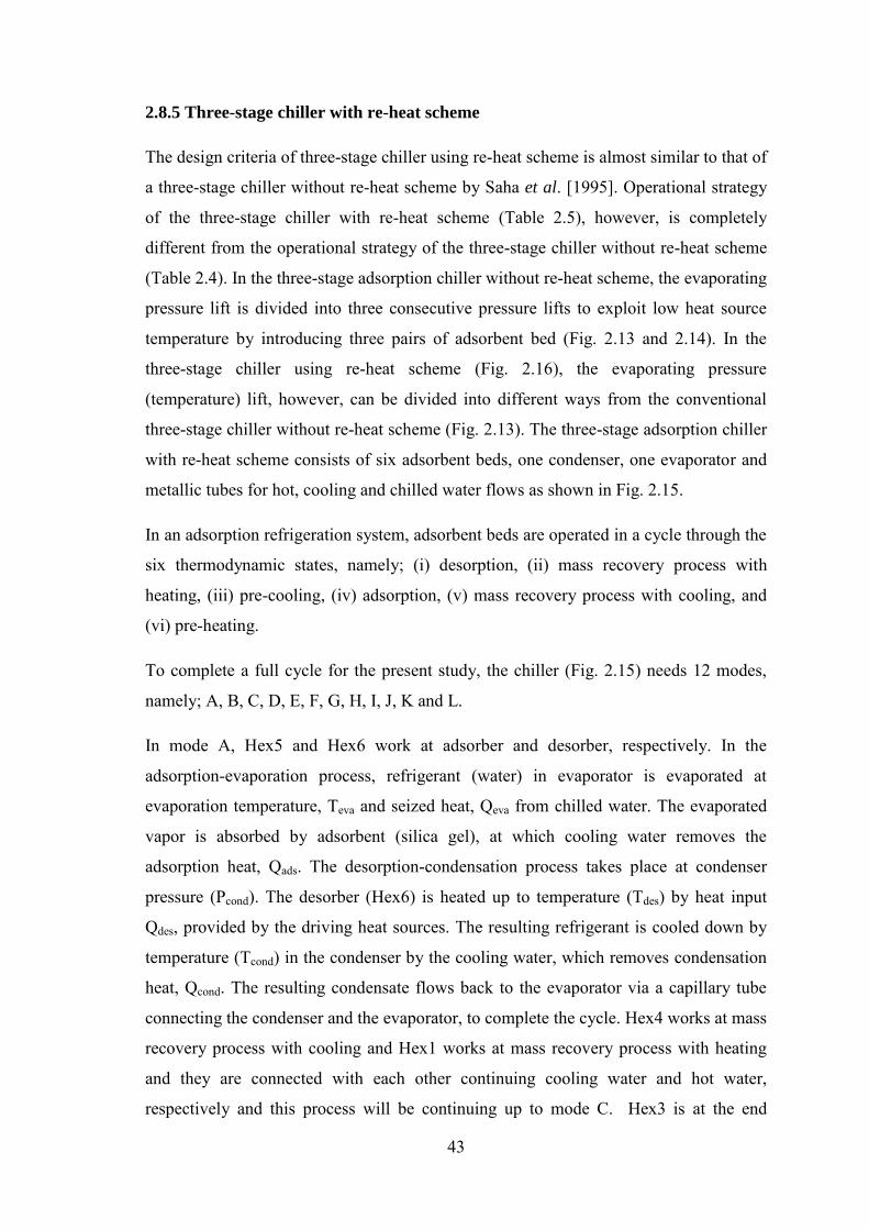
43
2.8.5 Three-stage chiller with re-heat scheme
The design criteria of three-stage chiller using re-heat scheme is almost similar to that of
a three-stage chiller without re-heat scheme by Saha et al. [1995]. Operational strategy
of the three-stage chiller with re-heat scheme (Table 2.5), however, is completely
different from the operational strategy of the three-stage chiller without re-heat scheme
(Table 2.4). In the three-stage adsorption chiller without re-heat scheme, the evaporating
pressure lift is divided into three consecutive pressure lifts to exploit low heat source
temperature by introducing three pairs of adsorbent bed (Fig. 2.13 and 2.14). In the
three-stage chiller using re-heat scheme (Fig. 2.16), the evaporating pressure
(temperature) lift, however, can be divided into different ways from the conventional
three-stage chiller without re-heat scheme (Fig. 2.13). The three-stage adsorption chiller
with re-heat scheme consists of six adsorbent beds, one condenser, one evaporator and
metallic tubes for hot, cooling and chilled water flows as shown in Fig. 2.15.
In an adsorption refrigeration system, adsorbent beds are operated in a cycle through the
six thermodynamic states, namely; (i) desorption, (ii) mass recovery process with
heating, (iii) pre-cooling, (iv) adsorption, (v) mass recovery process with cooling, and
(vi) pre-heating.
To complete a full cycle for the present study, the chiller (Fig. 2.15) needs 12 modes,
namely; A, B, C, D, E, F, G, H, I, J, K and L.
In mode A, Hex5 and Hex6 work at adsorber and desorber, respectively. In the
adsorption-evaporation process, refrigerant (water) in evaporator is evaporated at
evaporation temperature, Teva and seized heat, Qeva from chilled water. The evaporated
vapor is absorbed by adsorbent (silica gel), at which cooling water removes the
adsorption heat, Qads. The desorption-condensation process takes place at condenser
pressure (Pcond). The desorber (Hex6) is heated up to temperature (Tdes) by heat input
Qdes, provided by the driving heat sources. The resulting refrigerant is cooled down by
temperature (Tcond) in the condenser by the cooling water, which removes condensation
heat, Qcond. The resulting condensate flows back to the evaporator via a capillary tube
connecting the condenser and the evaporator, to complete the cycle. Hex4 works at mass
recovery process with cooling and Hex1 works at mass recovery process with heating
and they are connected with each other continuing cooling water and hot water,
respectively and this process will be continuing up to mode C. Hex3 is at the end

44
position of adsorption-evaporation process and Hex2 is at the end position of
desorption-condensation process and they are connected with each other continuing
cooling water and hot water, respectively, and this can be classified as two bed mass
recovery process. This time Hex1, Hex2, Hex3 and Hex4 are isolated from evaporated
and condensed. Here mass recovery occurs from bed to bed. When the concentration
levels of both beds Hex2 and Hex3 reach in nearly equilibrium levels, the warm up
process will start, called mode B (pre-heating or pre-cooling).
Mode B is the pre-heating for Hex2 and pre-cooling for Hex3. In pre-heating and pre-
cooling process, Hex2 and Hex3 are isolated from evaporator, condenser or any other
beds. Hot water is supplied to the bed Hex2 and cooling water is supplied to the bed
Hex3 for short time (30 s) in this period. In this mode, Hex5 works at mass recovery
process with cooling and Hex6 works at mass recovery process with heating and they
are connected with each other continuing cooling water and hot water, respectively and
this process will be continuing up to mode E. This time Hex5 and Hex6 are isolated
from evaporated and condensed.
In mode C, Hex3 works as adsober and Hex2 works as desorber. Hex4 is at the end
position of adsorption-evaporation process and Hex1 is at the end position of
desorption-condensation process and they are connected with each other continuing
cooling water and hot water, respectively, and this can be classified as two bed mass
recovery process. This time Hex4 and Hex1 are isolated from evaporated and
condensed. When the concentration levels of both beds Hex1 and Hex4 reach in nearly
equilibrium process will start, called mode D (pre-cooling or pre-heating).
In mode D, Hex4 is heated up by hot water, and Hex1 is cooled down by cooling water.
Mode D is warm up process for Hex4 and Hex1. In this time, Hex4 and Hex1 are
isolated from evaporator, condenser or any other beds. When the pressure of Hex4 is
nearly equal to the pressure of condenser then Hex4 is connected to condenser. When
the pressure of Hex1 is nearly equal to the pressure of evaporator then Hex1 is
connected to evaporator. In this mode, Hex3 works at mass recovery with cooling and
Hex2 works at mass recovery with heating, and they are connected with each other
continuing cooling water and hot water, respectively and this process will be continuing
up to mode G, and that can be classified as two bed mass recovery process. This time
Hex3 and Hex4 are isolated from evaporated and condensed.

45
In mode E, Hex1 works as adsorber and Hex4 works as desorber. Hex5 is at the end
position of adsorption-evaporation process and Hex6 is at the end position of
desorption-condensation process and they are connected with each other continuing
cooling water and hot water, respectively, and this can be classified as two bed mass
recovery process. This time Hex5 and Hex6 are isolated from evaporated and
condensed. When the concentration levels of both beds Hex6 and Hex5 reach in nearly
equilibrium process will start, called mode F (pre-cooling or pre-heating).
In mode F, Hex5 is heated up by hot water, and Hex6 is cooled down by cooling water.
Mode F is the warm up process for Hex5 and Hex6. In this time, Hex5 and Hex6 are
isolated from evaporator, condenser or any other beds. When the pressure of Hex5 is
nearly equal to the pressure of condenser then Hex5 is connected to condenser. When
the pressure of Hex6 is nearly equal to the pressure of evaporator then Hex6 is
connected to evaporator. In this time, Hex1 works at mass recovery process with
cooling and Hex4 works at mass recovery process with heating, and they are connected
with each other continuing cooling water and hot water, respectively and this process
will be continuing up to mode I, and that can be classified as two bed mass recovery
process. This time Hex4 and Hex1 are isolated from evaporated and condensed.
In mode G, Hex6 works as adsorber and Hex5 works as desorber. Hex3 is at the end
position of adsorption-evaporation process and Hex2 is at the end position of
desorption-condensation process and they are connected with each other continuing
cooling water and hot water, respectively, and this can be classified as two bed mass
recovery process. This time Hex3 and Hex2 are isolated from evaporated and
condensed. When the concentration levels of both beds Hex2 and Hex3 reach in nearly
equilibrium process will start, called mode H (pre-cooling or pre-heating).
In mode H, Hex3 is heated up by hot water, and Hex2 is cooled down by cooling water.
Mode H is the warm up process for Hex3 and Hex2. In this time, Hex2 and Hex3 are
isolated from evaporator, condenser or any other beds. When the pressure of Hex3 is
nearly equal to the pressure of condenser then Hex3 is connected to condenser. When
the pressure of Hex2 is nearly equal to the pressure of evaporator then Hex2 is
connected to evaporator. Hex6 works at mass recovery process with cooling and Hex5
works at mass recovery process with heating, and they are connected with each other
continuing cooling water and hot water, respectively and this process will be continuing

46
up to mode K, and that can be classified as two bed mass recovery process. This time
Hex5 and Hex6 are isolated from evaporated and condensed.
In mode I, Hex2 works as adsorber and Hex3 works as desorber. Hex1 is at the end
position of adsorption-evaporation process and Hex4 is at the end position of
desorption-condensation process and they are connected with each other continuing
cooling water and hot water, respectively, and this can be classified as two bed mass
recovery process. This time Hex1 and Hex4 are isolated from evaporated and
condensed. When the concentration levels of both beds Hex4 and Hex1 reach in nearly
equilibrium process will start, called mode J (pre-cooling or pre-heating).
In mode J, Hex1 is heated up by hot water, and Hex4 is cooled down by cooling water.
Mode J is the warm up process for Hex1 and Hex4. In this time, Hex1 and Hex4 are
isolated from evaporator, condenser or any other beds. When the pressure of Hex1 is
nearly equal to the pressure of condenser then Hex1 is connected to condenser. When
the pressure of Hex4 is nearly equal to the pressure of evaporator then Hex4 is
connected to evaporator. Hex2 works at mass recovery process with cooling and Hex3
works at mass recovery process with heating, and they are connected with each other
continuing cooling water and hot water, respectively and this process will be continuing
up to mode L, and that can be classified as two bed mass recovery process. This time
Hex2 and Hex3 are isolated from evaporated and condensed.
In mode K, Hex4 works as adsorber and Hex1 works as desorber. Hex6 is at the end
position of adsorption-evaporation process and Hex5 is at the end position of
desorption-condensation process and they are connected with each other continuing
cooling water and hot water, respectively, and this can be classified as two bed mass
recovery process. This time Hex6 and Hex5 are isolated from evaporated and
condensed. When the concentration levels of both beds Hex5 and Hex6 reach in nearly
equilibrium process will start, called mode L (pre-cooling or pre-heating).
In mode L, Hex6 is heated up by hot water, and Hex5 is cooled down by cooling water.
Mode L is the warm up process for Hex6 and Hex5. In this time, Hex5 and Hex6 are
isolated from evaporator, condenser or any other beds. Hex4 works at mass recovery
process with cooling and Hex1 works at mass recovery process with heating, and they
are connected with each other continuing cooling water and hot water, respectively and
that can be classified as two bed mass recovery process. This time Hex1 and Hex4 are

47
isolated from evaporated and condensed. The mode L is the last process and after this
mode, all return to mode A (Table 2.5).
In the conventional three-stage chiller without re-heat scheme, lower four beds never
interact with the condenser, and the middle two beds never interact with either
evaporator or condenser. However, in the three-stage chiller using re-heat scheme, all
beds go through all processes and also interact with the condenser and evaporator one
by one. The operational strategy of the thee-stage chiller using re-heat scheme is
presented in (Table 2.5).
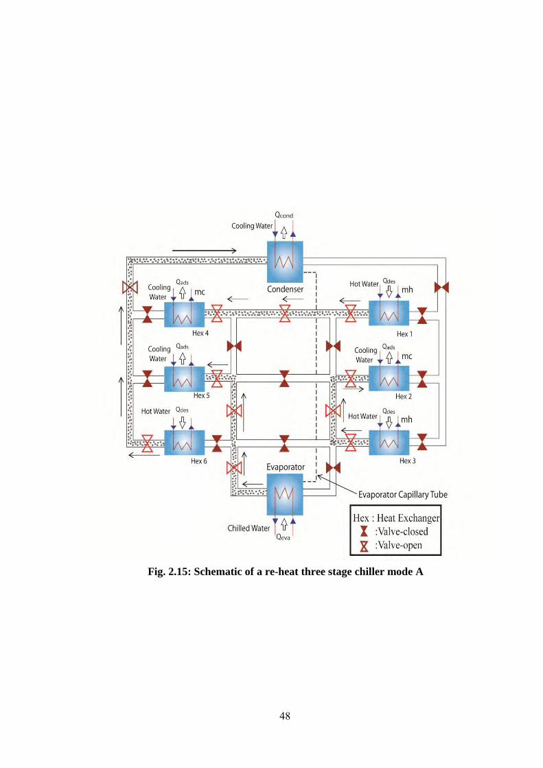
48
Fig. 2.15: Schematic of a re-heat three stage chiller mode A
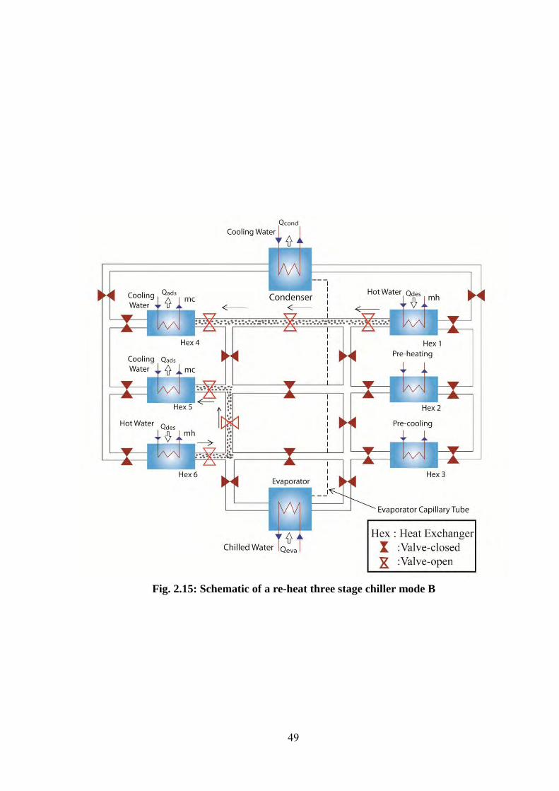
49
Fig. 2.15: Schematic of a re-heat three stage chiller mode B
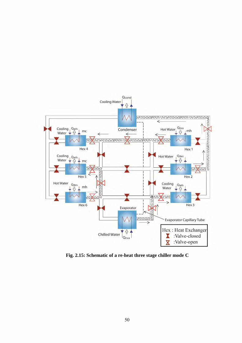
50
Fig. 2.15: Schematic of a re-heat three stage chiller mode C

51
Fig. 2.15: Schematic of a re-heat three stage chiller mode D

52
Fig. 2.15: Schematic of a re-heat three stage chiller mode E

53
Fig. 2.15: Schematic of a re-heat three stage chiller mode F

54
Fig. 2.15: Schematic of a re-heat three stage chiller mode G

55
Fig. 2.15: Schematic of a re-heat three stage chiller mode H
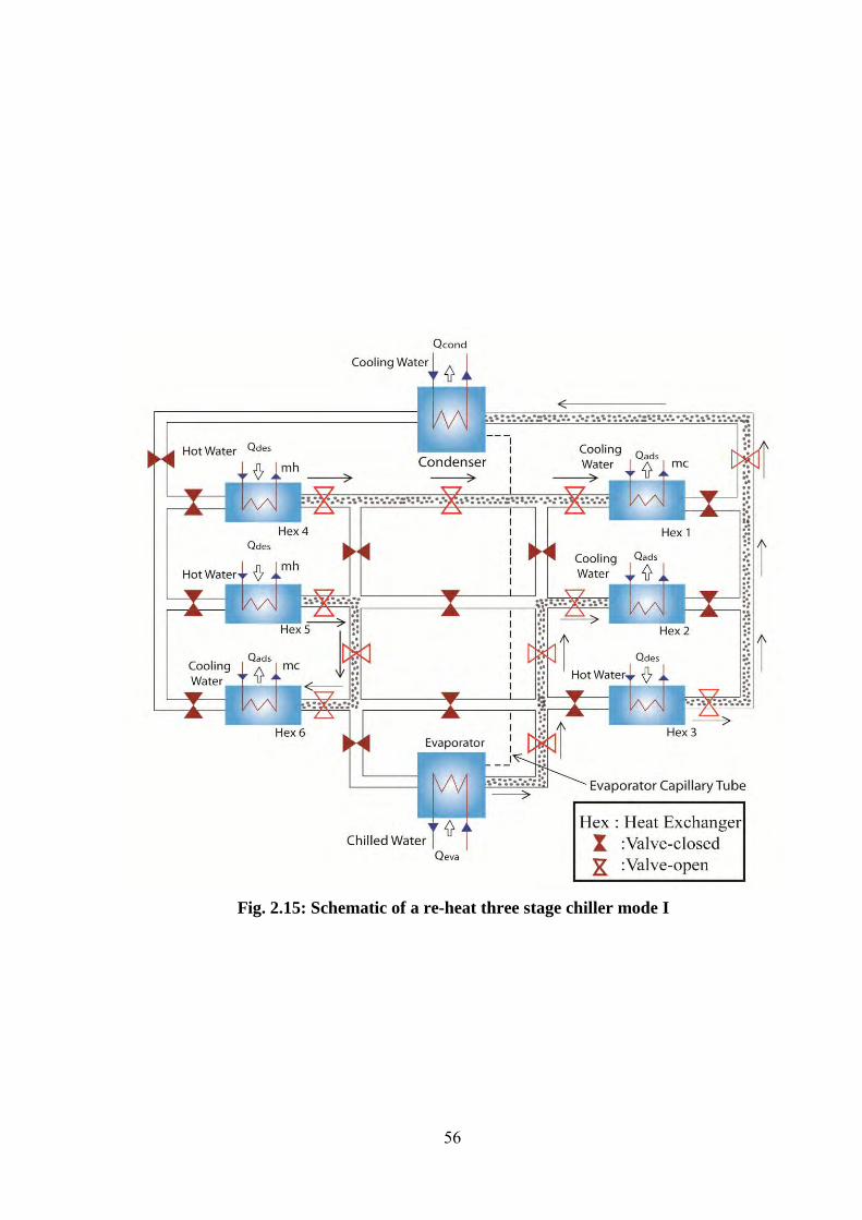
56
Fig. 2.15: Schematic of a re-heat three stage chiller mode I
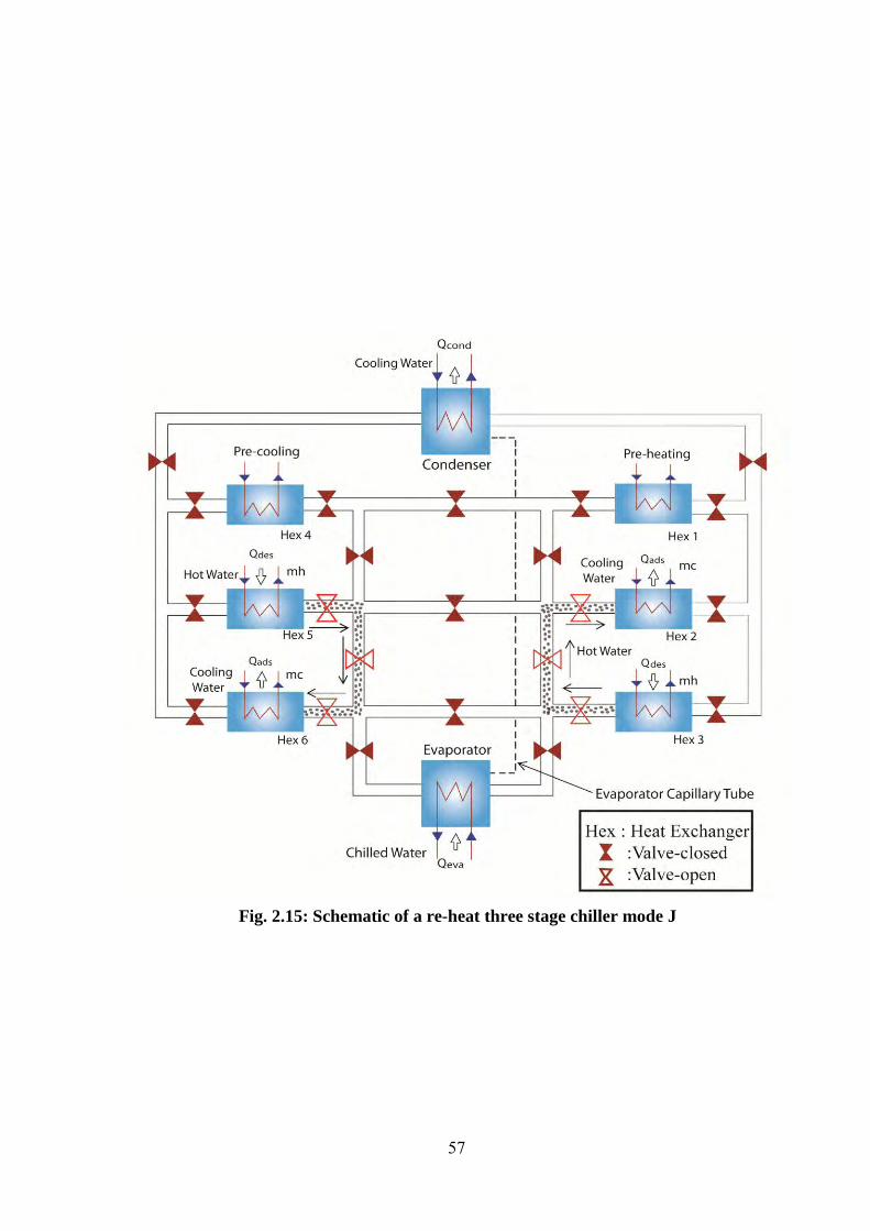
57
Fig. 2.15: Schematic of a re-heat three stage chiller mode J
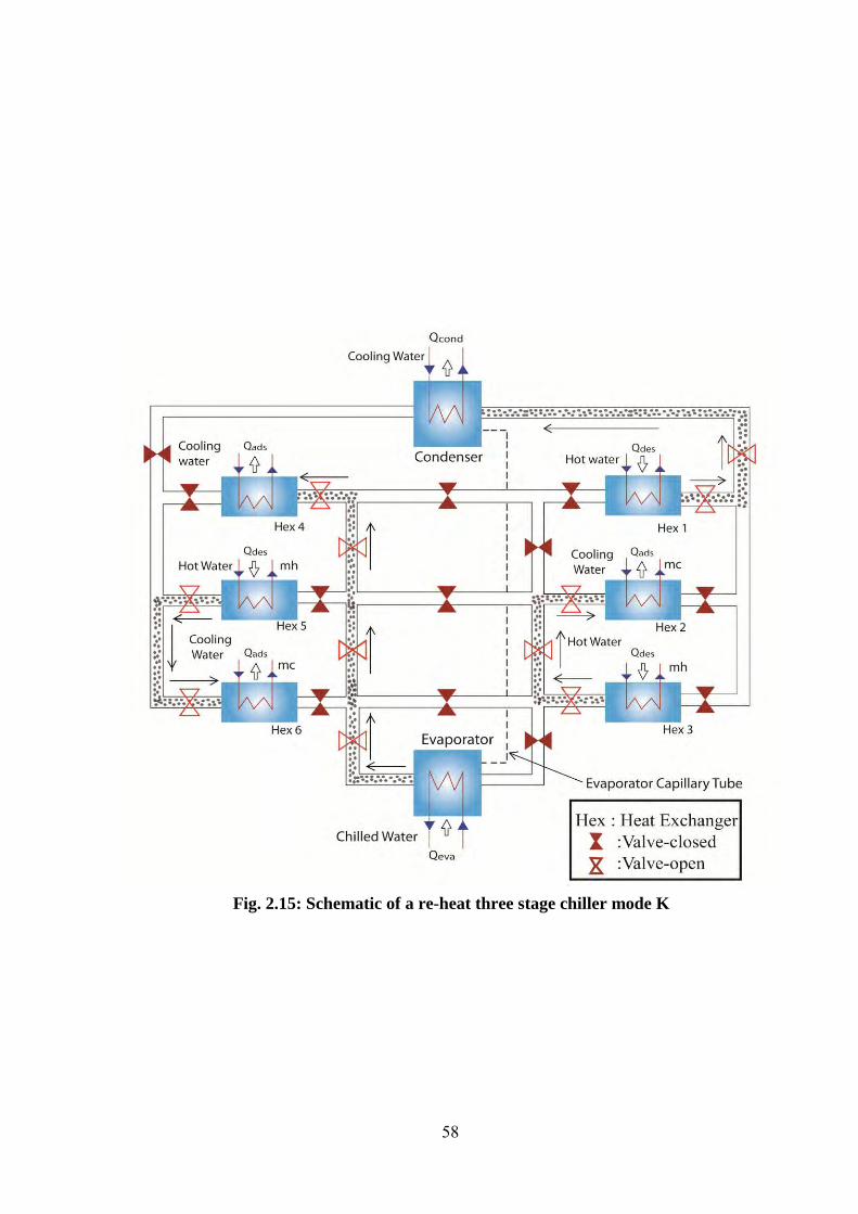
58
Fig. 2.15: Schematic of a re-heat three stage chiller mode K
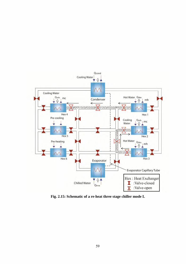
59
Fig. 2.15: Schematic of a re-heat three stage chiller mode L

60
Fig. 2.16: Conceptual P-T-X diagram for a three-stage chiller with re-heat
Table 2.5: Operational strategies of a three-stage adsorption chiller with re-heat

CHAPTER THREE
Mathematical and Numerical Modeling
3.1 Energy Balance for the Adsorber/Desorber
Adsorption and desorption heat balances are expressed by identical equations, where
heat transfer fluid (water) temperature terms and indicate cooling water upon
adsorption and of water upon desorption. T stands for bed temperature. In addition, the
adsorbent bed temperature, pressure and concentration are assumed to be uniform all
over the adsorbent bed. The specific of refrigerant (water) in liquid phase is taken as our
system works in low the concentration range. The heat transfers and energy balance
equations for the adsorbent beds can be described as follows:
(3.1)
(
+ (3.2)
where
p
The importance of heat transfer parameters is described in Eq. (3.1). These parameters
are heat transfer area and heat transfer coefficient . The left hand side of the
adsorber/desorber energy balance Eq. (3.2) provides the amount of sensible heat
required to cool or heat the silica-gel (s), the water (w) as well as metallic (hex) parts of
the heat exchanger during adsorption or desorption. In addition, the first term on the
right hand side of Eq. (3.2) stands for the release of adsorption heat or the input of
desorption heat, while the second and third terms represent for the sensible heat of the
adsorbed vapor. And, the last term on the right hand side of Eq. (3.2) gives the total
amount of heat released to the cooling water upon adsorption or provided by the hot
water for desorption. As all beds are assumed to be well insulated, Eq. (3.2) does not
account for external heat losses to the environment.

62
3.2 Energy Balance for the Evaporator
In this study, it is considered that the tube bank surface is able to hold a certain
maximum amount of condensate and the condensate would flow into the evaporator
easily. The heat transfers and energy balance Eq. (3.3) for the evaporator can be written
as
(3.3)
3
(3.4)
where the suffixes chill and eva indicate chilled and evaporator respectively.
The sensible heat required by the liquid refrigerant (w) and the metal of heat exchanger
tubes in the evaporator can be found from the left hand side of Eq. (3.4). The first term
on the right hand side of Eq. (3.4) represents the latent heat of evaporation (L) for the
amount of refrigerants adsorbed
, while the second term gives the sensible heat
required to cool down the incoming condensate from the condensation temperature
to evaporation temperature and the last term indicates the total amount of
heat given away by the chilled water.
3.3 Energy Balance for the Condenser
The heat transfers and energy balance Eq. (3.3) for the condenser can be written as
(3.5)
3
(3.6)
Where the subscripts cw and cond indicate cooling water and condenser, respectively.
The left hand side of Eq. (3.6) represents the sensible heat required by the metallic parts
of heat exchanger tubes due to the temperature variations in the condenser. On the right
hand side, the first term gives the latent heat of vaporization ( ) for the amount of
refrigerant desorbed
, the second term shows the amount of sensible heat
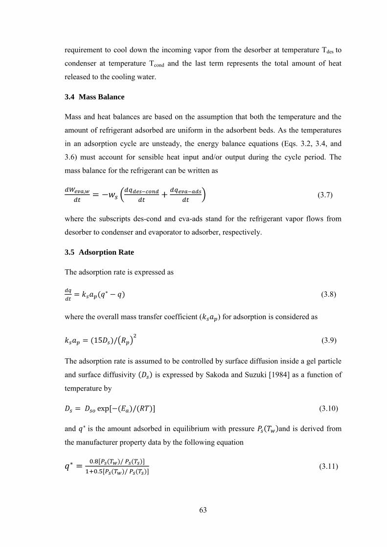
63
requirement to cool down the incoming vapor from the desorber at temperature Tdes to
condenser at temperature Tcond and the last term represents the total amount of heat
released to the cooling water.
3.4 Mass Balance
Mass and heat balances are based on the assumption that both the temperature and the
amount of refrigerant adsorbed are uniform in the adsorbent beds. As the temperatures
in an adsorption cycle are unsteady, the energy balance equations (Eqs. 3.2, 3.4, and
3.6) must account for sensible heat input and/or output during the cycle period. The
mass balance for the refrigerant can be written as
(3.7)
where the subscripts des-cond and eva-ads stand for the refrigerant vapor flows from
desorber to condenser and evaporator to adsorber, respectively.
3.5 Adsorption Rate
The adsorption rate is expressed as
(3.8)
where the overall mass transfer coefficient ( ) for adsorption is considered as
(3.9)
The adsorption rate is assumed to be controlled by surface diffusion inside a gel particle
and surface diffusivity is expressed by Sakoda and Suzuki [1984] as a function of
temperature by
(3.10)
and is the amount adsorbed in equilibrium with pressure and is derived from
the manufacturer property data by the following equation
(3.11)
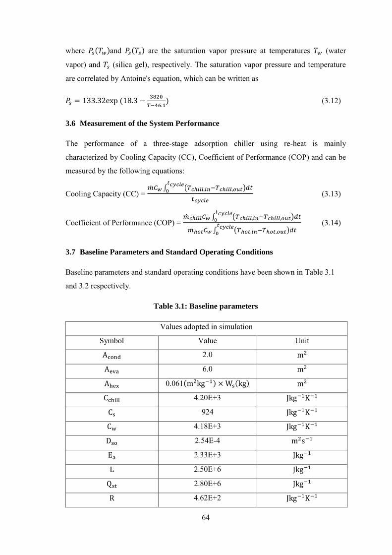
64
where and are the saturation vapor pressure at temperatures (water
vapor) and (silica gel), respectively. The saturation vapor pressure and temperature
are correlated by Antoine's equation, which can be written as
(3.12)
3.6 Measurement of the System Performance
The performance of a three-stage adsorption chiller using re-heat is mainly
characterized by Cooling Capacity (CC), Coefficient of Performance (COP) and can be
measured by the following equations:
Cooling Capacity (CC) =
(3.13)
Coefficient of Performance (COP) =
(3.14)
3.7 Baseline Parameters and Standard Operating Conditions
Baseline parameters and standard operating conditions have been shown in Table 3.1
and 3.2 respectively.
Table 3.1: Baseline parameters
Values adopted in simulation
Symbol Value Unit
2.0
6.0
0.061
4.20E+3
924
4.18E+3
2.54E-4
2.33E+3
2.50E+6
2.80E+6
4.62E+2

65
0.30E-3
1000
3900
750
5800
5
25
16
Table 3.2: Standard operating conditions
Temperature Flow rate
Hot water 60 0.4
Cooling water 30 0.74(=0.4 ads+0.34 cond)
Chilled water 14 0.11
Cycle Time 4400 s = (1570 for ads/des + 600 for mr + 30 for ph/pc) s×2
ads/des = adsorption/desorption, mr = mass recovery, ph/pc = pre-heat/pre-cool
3.8 Solution Procedure (Finite difference technique)
In the present study, a cyclic simulation computer program is developed to predict the
performance of the innovative three-stage chiller using the re-heat scheme. The system
of differential Eqs. (3.1 — 3.12) (Adsorber/desorber energy balance equations,
Evaporator energy lance, Condenser energy balance, Mass balance, Adsorption rate) are
solved by employing finite difference approximation with a time step 1 s. The results
taken in the study are from the cyclic steady state conditions. A real chiller starts its
function with unbalanced conditions. However, after a few cycles it reaches its cyclical
steady state condition. Thus, an iteration process has been used in solution technique to
fix all the initial values for the cyclic steady state conditions. From the beginning of the
solution process, the initial values are considered and lastly those are adjusted by this
iteration process.
When two beds are connected with evaporator or condenser, the vapor pressure is
unknown that are calculated through the Antoine’s equations as the vapor temperature is
calculated from the energy balance equation of evaporator or condenser. It is, however,
difficult to calculate the saturated vapor pressure when two beds are connected with
66
each other, which are essential for the calculation of adsorption/desorption rate inside
the adsorbent beds. In the state, the pressure assumed and the amounts of vapor
adsorbed/desorbed beds are calculated. Conceptually, the desorbed vapor is equal to the
amount of adsorbed vapor by the other beds. If these amounts are not equal, then vapor
pressure is adjusted for next iteration. Once the satisfactory convergence criterion is
achieved, then process goes for the next time step. The convergence criterion for all
cases of present study has been taken as .
Elaborate calculations for heat transfer equation (3.1) and energy balance
equation (3.2) for desorber:
For heat transfer equation:
We know the heat transfer equation,
Again, we know from thermodynamics, Logarithms Mean Temperature difference,
The heat equation for water is
or, =
or,
or,
or,
or,
or,
or,

67
For energy balance equation:
+
or,
(3.15)
Let,
The Eq. (3.15) becomes,
2
(3.16)
Let,
The Eq. (3.16) becomes,
3
3
or,
3
or,
(3.17)
Let,
The Eq. (3.17) becomes,
3
3
Again let,
Then Eq. (3.17) takes the form,
3
3 (3.18)
which implies,
3

68
3.9 Methodology
A cyclic simulation computer technique has been modified to predict the performance
of the innovative three-stage chiller using re-heat. A finite difference approximation has
been used to solve the system. The results have been implemented in the study from the
cyclic steady state conditions. A real chiller starts its operation with unbalanced
conditions, however, after a few cycles it reaches cyclic steady state condition.
Therefore, an iteration process has been employed in solution procedure to fix all the
initial values for the cyclic steady state conditions. In the beginning of the solution
process, the initial values have been assumed and finally those have been adjusted by
the iteration process.

CHAPTER FOUR
Results and Discussion
In the present treatment, the effect of thermal conductance of sorption element,
evaporator and condenser on the performance of the chiller, chilled water outlet and
their improvement ratio are discussed. It should be noted that the total silica gel mass of
the six beds are considered to be same. However, the mass ratio of upper, middle and
lower beds are kept 1:3:4 fixed.
4.1 Effect of Thermal Conductance of Adsorber on CC and COP
In Figs. 4.1(a) and 4.1(b), numerical values of Cooling Capacity (CC) and Coefficient
of Performance (COP) are depicted against the driving heat source inlet temperatures
which vary from 45 to . Four lines are drawn for four different thermal
conductance [UA] values of adsorber; namely, , ,
, , respectively. It is observed from these figures
that both CC and COP increase with the increase of heat source temperature in all cases.
It is noticed that CC and COP increase as UA of adsorber increases. This is because
large UA values mean large heat transfer area or high heat transfer coefficient or both.
This leads to accumulation of increased refrigerant adsorbent elements inside and
enhance performance.
Fig. 4.1(a): Effect of Thermal conductance [UA] of adsorber on cooling capacity.

70
Fig. 4.1(b): Effect of Thermal conductance [UA] of adsorber on COP.
4.2 Effect of Thermal Conductance of Condenser on CC and COP
From Figs. 4.2(a) and 4.2(b), it is seen that CC and COP increase when both UA of
condenser and heat source temperature increase. It is observed that both CC and COP
increase up to its maximum value where the value of UA of condenser is equal to
. UA value of condenser is greater than is no longer effective for
the present baseline condition.
Fig. 4.2(a): Effect of Thermal conductance [UA] of condenser on cooling capacity.

71
Fig. 4.2(b): Effect of Thermal conductance [UA] of condenser on COP.
4.3 Effect of Thermal Conductance of Evaporator on CC and COP
In Figs. 4.3(a) and 4.3(b), It is observed from these figures that both CC and COP
increase with the increase of heat source temperature in all cases if the value of UA
evaporator increases. Another important observation is that if the value of UA of
evaporator is greater than , both CC and COP show insignificant effect.
Fig. 4.3(a): Effect of Thermal conductance [UA] of evaporator on cooling capacity.
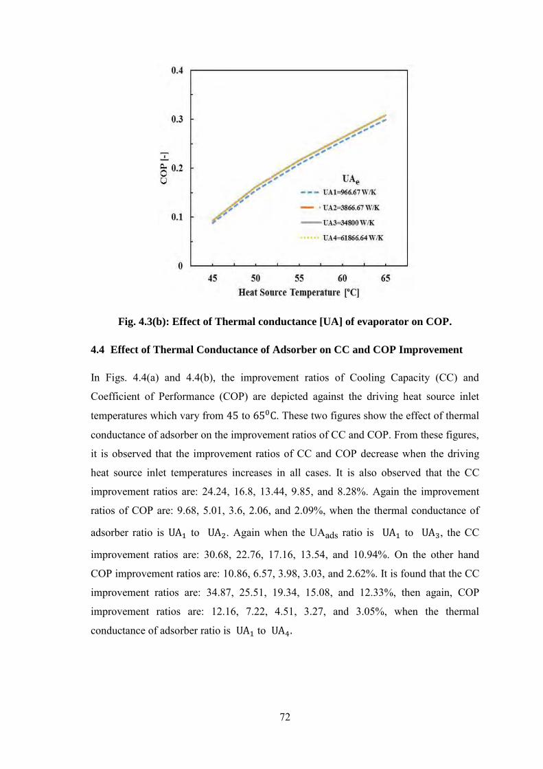
72
Fig. 4.3(b): Effect of Thermal conductance [UA] of evaporator on COP.
4.4 Effect of Thermal Conductance of Adsorber on CC and COP Improvement
In Figs. 4.4(a) and 4.4(b), the improvement ratios of Cooling Capacity (CC) and
Coefficient of Performance (COP) are depicted against the driving heat source inlet
temperatures which vary from to . These two figures show the effect of thermal
conductance of adsorber on the improvement ratios of CC and COP. From these figures,
it is observed that the improvement ratios of CC and COP decrease when the driving
heat source inlet temperatures increases in all cases. It is also observed that the CC
improvement ratios are: 24.24, 16.8, 13.44, 9.85, and 8.28%. Again the improvement
ratios of COP are: 9.68, 5.01, 3.6, 2.06, and 2.09%, when the thermal conductance of
adsorber ratio is to . Again when the UAads ratio is to , the CC
improvement ratios are: 30.68, 22.76, 17.16, 13.54, and 10.94%. On the other hand
COP improvement ratios are: 10.86, 6.57, 3.98, 3.03, and 2.62%. It is found that the CC
improvement ratios are: 34.87, 25.51, 19.34, 15.08, and 12.33%, then again, COP
improvement ratios are: 12.16, 7.22, 4.51, 3.27, and 3.05%, when the thermal
conductance of adsorber ratio is to

73
Fig. 4.4(a): Effect of Thermal conductance [UA] of adsorber on CC improvement.
Fig. 4.4(b): Effect of Thermal conductance [UA] of adsorber on COP improvement.

74
4.5 Effect of Thermal Conductance of Condenser on CC and COP Improvement
The two Figs. 4.5(a) and 4.5(b) show the effect of thermal conductance of condenser on
the improvement ratios of CC and COP. From the Fig. 4.5(a), it is seen that the
improvement ratios of CC are high when the driving heat source inlet temperature is
50ºC, after that it decreases gradually. From the Fig 4.5(b), it is also seen that the
improvement ratios of COP are very high when the driving heat source inlet temperature
is 50ºC, later it decreases rapidly up to 55ºC, after that it decreases linearly. It is
observed that the CC improvement ratios are: 3.59, 3.69, 2.44, 1.74, and 1.11%, then
again, COP improvement ratios are: 3.68, 4.46, 3.60, 3.59, and 3.53%, when the thermal
conductance of condenser ratio is to Again the UAc ratio is to , the
CC improvement ratios are: 3.62, 3.72, 2.47, 1.75, and 1.14%, Conversely, COP
improvement ratios are: 3.68, 4.46, 3.65, 3.63, and 3.60%. It is also seen that the CC
improvement ratios are: 3.62, 3.72, 2.47, 1.75, and 1.14%, On the other hand, COP
improvement ratios are: 3.68, 4.46, 3.65, 3.63, and 3.6%, the thermal conductance of
UAc ratio is to . On the other hand, from these figures it is realized that there
is no improvement of CC and COP among the ratios of, to to and
to , because they are very marginal.
Fig. 4.5(a): Effect of Thermal conductance [UA] of condenser on CC improvement.

75
Fig. 4.5(b): Effect of Thermal conductance [UA] of condenser on
COP improvement.
4.6 Effect of Thermal Conductance of Evaporator on CC and COP Improvement
In Figs. 4.6(a) and 4.6(b), it is seen that the improvement ratios of CC and COP
decrease when the driving heat source inlet temperature increases up to 60ºC, after that
they increase. From these figures, it is also observed that there is no improvement of CC
and COP, because the improvement ratios of to , to and to
are almost same. It is seen that the CC improvement ratios are: 5.63, 5.06, 4.39,
4.11, and 4.74%, on the other hand, COP improvement ratios are: 5.45, 4.67, 3.5, 2.78,
and 2.98%, when the thermal conductance of evaporator ratio is to . Again
when the UAe ratio is to , the CC improvement ratios are: 5.66, 5.10, 4.39,
4.13, and 4.75% as well as COP improvement ratios are: 5.45, 4.73, 3.50, 2.82 and
2.98%. It is also seen that the CC improvement ratios are: 5.66, 5.10, 4.39, 4.13, and
4.75%, then again, COP improvement ratios are: 5.45, 4.73, 3.50, 2.82 and 2.98%, when
the thermal conductance of evaporator ratio is to .
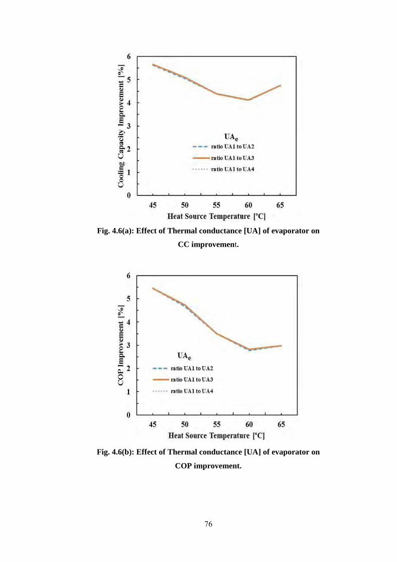
76
Fig. 4.6(a): Effect of Thermal conductance [UA] of evaporator on
CC improvement.
Fig. 4.6(b): Effect of Thermal conductance [UA] of evaporator on
COP improvement.

77
4.7 Effect of Thermal Conductance on Chilled Water Outlet
In an adsorption chiller, the chilled water for air-condition purposes is obtained from the
outlet of the chilled water. Generally, less chilled water outlet temperature is expected,
while the requirement of cooling capacity is high. The chilled water outlet temperature,
however, affects cooling demand of the demand side. Therefore, the requirement of
chilled water outlet temperature is very important. From this context, the effect of heat
source temperature as well as UA of adsorber, evaporator and condenser are presented
in Figs. 4.7(a), 4.7(b) and 4.7(c). It may be seen that the chiller with different level of
heat source temperature provides different level chilled water outlet temperature. It can
be also seen that the higher is the heat source temperature; the lower is the chilled water
outlet temperature. It is seen that chilled water outlet temperature decreases with the
increases of UA value of adsorber increases in all cases. It is also seen that chilled water
outlet temperature gives optimum results when the UA value of evaporator and
condenser are equal two 34800 and 7800 W/K, respectively.
Fig. 4.7(a): Effect of Thermal conductance [UA] of adsorber
on chilled water outlet.

78
Fig. 4.7(b): Effect of Thermal conductance [UA] of evaporator
on chilled water outlet.
Fig. 4.7(c): Effect of Thermal conductance [UA] of condenser
on chilled water outlet.
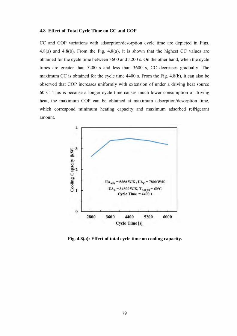
79
4.8 Effect of Total Cycle Time on CC and COP
CC and COP variations with adsorption/desorption cycle time are depicted in Figs.
4.8(a) and 4.8(b). From the Fig. 4.8(a), it is shown that the highest CC values are
obtained for the cycle time between 3600 and 5200 s. On the other hand, when the cycle
times are greater than 5200 s and less than 3600 s, CC decreases gradually. The
maximum CC is obtained for the cycle time 4400 s. From the Fig. 4.8(b), it can also be
observed that COP increases uniformly with extension of under a driving heat source
60°C. This is because a longer cycle time causes much lower consumption of driving
heat, the maximum COP can be obtained at maximum adsorption/desorption time,
which correspond minimum heating capacity and maximum adsorbed refrigerant
amount.
Fig. 4.8(a): Effect of total cycle time on cooling capacity.

80
Fig. 4.8(b): Effect of total cycle time on COP.
4.9 Effect of Mass Recovery Time on CC and COP
Mass recovery time is very simple but effective to operate. For operating conditions
such as high-condensing temperatures, low-evaporation temperatures, or low-generation
temperatures, mass recovery operation is strongly recommended by Wang [2001]. From
the Figs. 4.9(a) and 4.9(b), it is observed that CC and COP increase with the increase of
mass recovery time up to 600 and 500 s respectively. Another observation is that both
CC and COP decrease when mass recovery time is greater than 600 and 500 s
respectively. It should be mentioned that in this case driving heat source temperature is
60ºC fixed.
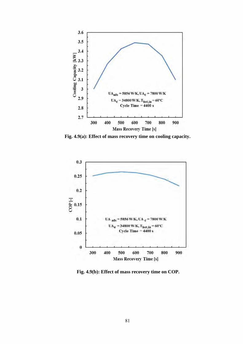
81
Fig. 4.9(a): Effect of mass recovery time on cooling capacity.
Fig. 4.9(b): Effect of mass recovery time on COP.
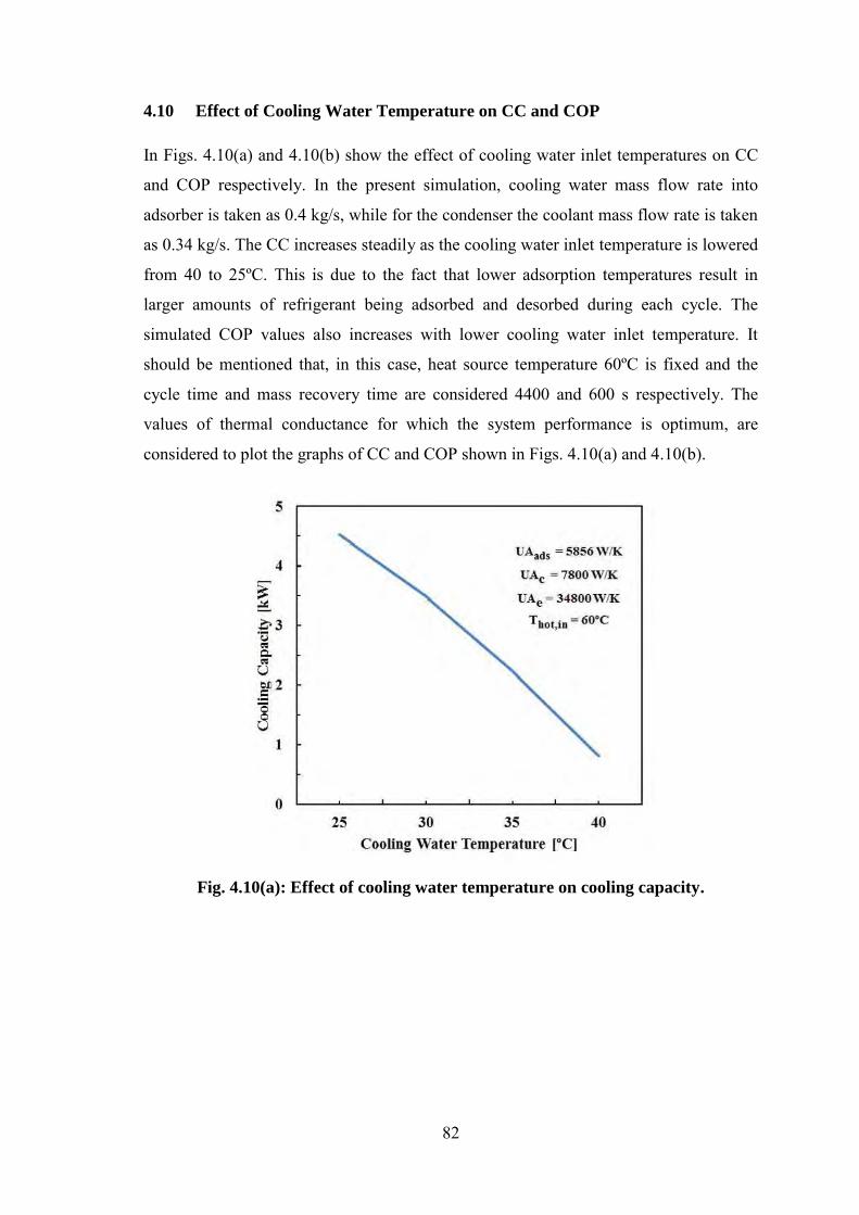
82
4.10 Effect of Cooling Water Temperature on CC and COP
In Figs. 4.10(a) and 4.10(b) show the effect of cooling water inlet temperatures on CC
and COP respectively. In the present simulation, cooling water mass flow rate into
adsorber is taken as 0.4 kg/s, while for the condenser the coolant mass flow rate is taken
as 0.34 kg/s. The CC increases steadily as the cooling water inlet temperature is lowered
from 40 to 25ºC. This is due to the fact that lower adsorption temperatures result in
larger amounts of refrigerant being adsorbed and desorbed during each cycle. The
simulated COP values also increases with lower cooling water inlet temperature. It
should be mentioned that, in this case, heat source temperature 60ºC is fixed and the
cycle time and mass recovery time are considered 4400 and 600 s respectively. The
values of thermal conductance for which the system performance is optimum, are
considered to plot the graphs of CC and COP shown in Figs. 4.10(a) and 4.10(b).
Fig. 4.10(a): Effect of cooling water temperature on cooling capacity.
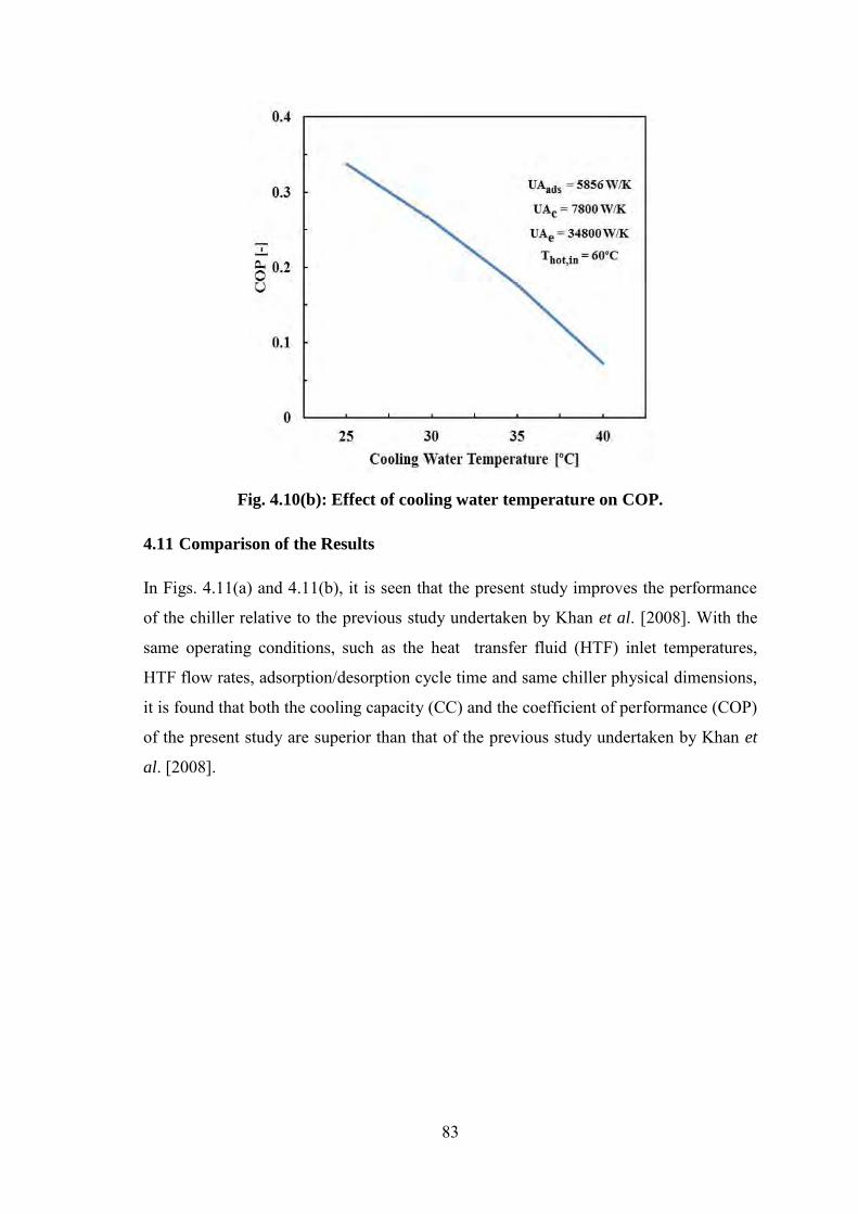
83
Fig. 4.10(b): Effect of cooling water temperature on COP.
4.11 Comparison of the Results
In Figs. 4.11(a) and 4.11(b), it is seen that the present study improves the performance
of the chiller relative to the previous study undertaken by Khan et al. [2008]. With the
same operating conditions, such as the heat transfer fluid (HTF) inlet temperatures,
HTF flow rates, adsorption/desorption cycle time and same chiller physical dimensions,
it is found that both the cooling capacity (CC) and the coefficient of performance (COP)
of the present study are superior than that of the previous study undertaken by Khan et
al. [2008].

84
Fig. 4.11(a): Comparison of CC between the present study and Khan et al. [2008].
Fig. 4.11(b): Comparison of COP between the present study and Khan et al. [2008].
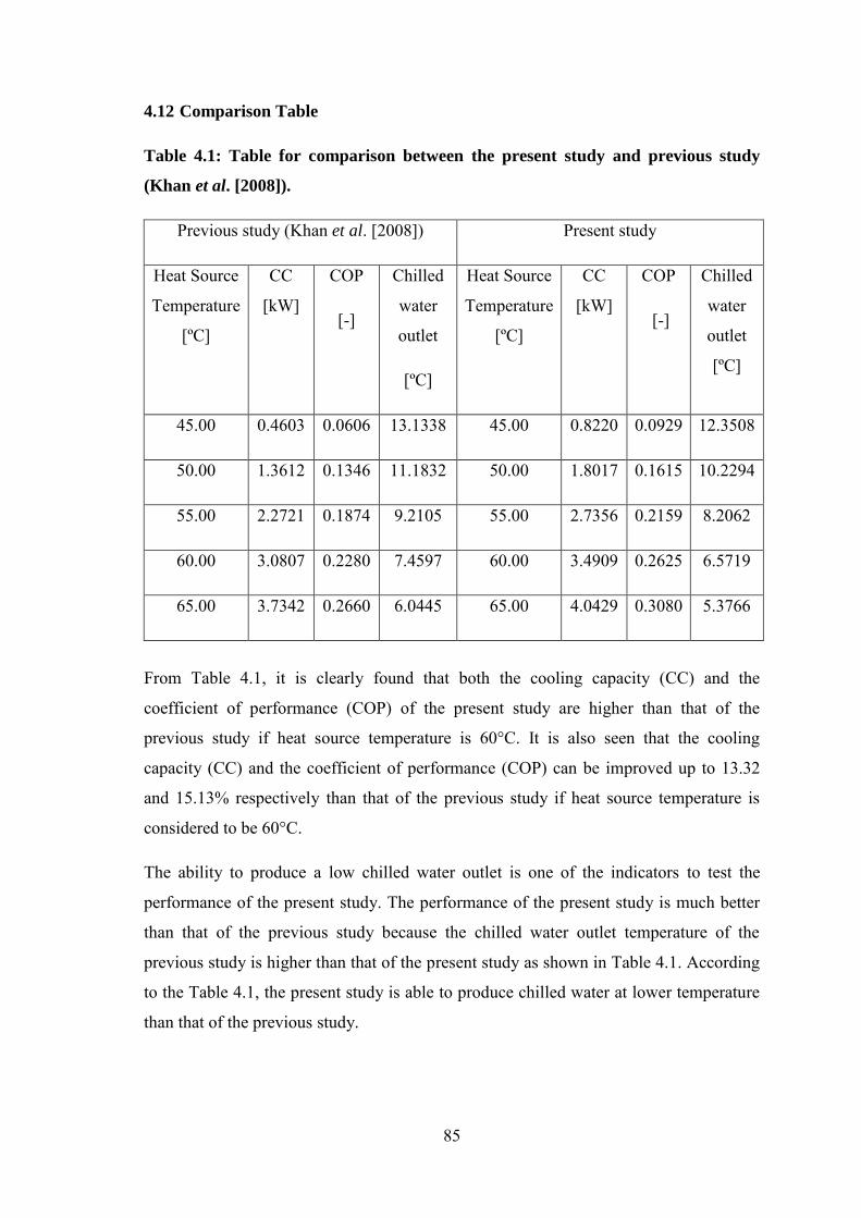
85
4.12 Comparison Table
Table 4.1: Table for comparison between the present study and previous study
(Khan et al. [2008]).
Previous study (Khan et al. [2008]) Present study
Heat Source
Temperature
[ºC]
CC
[kW]
COP
[-]
Chilled
water
outlet
[ºC]
Heat Source
Temperature
[ºC]
CC
[kW]
COP
[-]
Chilled
water
outlet
[ºC]
45.00 0.4603 0.0606 13.1338 45.00 0.8220 0.0929 12.3508
50.00 1.3612 0.1346 11.1832 50.00 1.8017 0.1615 10.2294
55.00 2.2721 0.1874 9.2105 55.00 2.7356 0.2159 8.2062
60.00 3.0807 0.2280 7.4597 60.00 3.4909 0.2625 6.5719
65.00 3.7342 0.2660 6.0445 65.00 4.0429 0.3080 5.3766
From Table 4.1, it is clearly found that both the cooling capacity (CC) and the
coefficient of performance (COP) of the present study are higher than that of the
previous study if heat source temperature is 60°C. It is also seen that the cooling
capacity (CC) and the coefficient of performance (COP) can be improved up to 13.32
and 15.13% respectively than that of the previous study if heat source temperature is
considered to be 60°C.
The ability to produce a low chilled water outlet is one of the indicators to test the
performance of the present study. The performance of the present study is much better
than that of the previous study because the chilled water outlet temperature of the
previous study is higher than that of the present study as shown in Table 4.1. According
to the Table 4.1, the present study is able to produce chilled water at lower temperature
than that of the previous study.
CHAPTER FIVE
Conclusions
5.1 Conclusions
In this study, the effect of thermal conductance on the performance of a three-stage
adsorption chiller with re-heat scheme has been investigated numerically. A finite
difference iterative technique has beeen used in analyzing the solution procedure and
mass ratio of upper, middle and lower bed is kept 1:3:4 fixed. The analysis concludes:
As the heat source temperatures increases, CC and COP increase. However,
chilled water outlet is decreased.
For large values of thermal conductance of sorption elements, condenser and
evaporator, the system gives better performance.
COP increases as the total cycle time increases. The highest value of CC is
obtained for the cycle time between 3600 and 5200 s.
The improvement ratio in CC and COP however increase with the decreases of
heat source temperature as well as increase the thermal conductance of adsorber,
condenser and evaporator.
CC and COP increase with the increase of mass recovery time up to 600 and
500 s, respectively. On the other hand, CC and COP decrease when mass
recovery time is greater than 600 and 500 s, respectively.
CC and COP give optimum results as the cooling water temperature is very low
(approximately 25ºC).
Compare the performance of the study by Khan et al. [2008], both the CC and
COP have improved by 13.32 and 15.13% respectively while the hot water and
cooling water temperature is at and , respectively.

87
5.2 Extension of this Work
In this analysis, the system performance is investigated for different phase of
parameters. The present study may be extended further. Some recommendations for
future investigations are listed below:
In the present study, the effect of thermal conductance of three-stage adsorption
chiller with re-heat scheme with different mass allocation has been investigated
numerically. It may be extended as the number of bed and stages are changed.
In this analysis, silica gel-water is considered as adsorbent-refrigerant pairs.
New adsorbent-refrigerant pairs such as SiO2/CaCl2 can be added so that the
problem may be extended.
In this investigation, the flow rate of hot water, cool water and chilled water are
kept fixed. If the flow rate is changed then further extension of this research is
possible.
The research may be extended by changing both silica gel and bed sizes.
REFERENCES
Akahira, A., Alam, K.C.A., Hamamoto, Y., Akisawa, A., Kashiwagi, T.,
“Experimental investigation of mass recovery adsorption refrigeration cycle,” Int. J.
of Refrigeration, 28(4), (2005), pp. 565-572.
Alam, K.C.A., Hamamoto, Y., Akisawa, A., Kashiwagi, T., “Kashiwagi, Advanced
adsorption chiller driven by low temperature heat source,” Proceeding of
2lstInternational Congress of refrigeration (CD ROM), Washington, DC, Paper
no.136, (2003).
Barrer, R.M., “Zeolites and clay minerals as sorbents and molecular sieves”,
Academic Press, New York, NY, (1978).
Ben Amar, N., Sun, L.M., Meunier, F., “Numerical analysis of adsorptive
temperature wave regenerative heat pump,” Appl. Thermal Eng., 16(5), (1996), pp.
405-418.
Boelman, E.C., Saha, B.B., Kashiwagi, T., “Experimental investigation of a silica-gel
water adsorption refrigeration cycles the influence of operating conditions on cooling
output and COP,” ASHRAE Trans Res, 101(2), (1995), pp. 358-366.
Calm, J.M., “Emissions and environmental impacts from air-conditioning and
refrigeration systems”, Int. J. of Refrigeration, 25(3), (2002), pp. 293-305.
Cargocaire, “The dehumidification handbook,” Cargocaire Eng. Corp. Amesbury,
(1982), pp. 14-15.
Critoph, R.E., “Activated carbon adsorption cycles for refrigeration and heat
pumping,” Carbon, 27(1), (1989), pp. 63-70.
Critoph, R.E., “Forced convection adsorption cycle with packed bed heat
regeneration,” Int. J. of Refrigeration, 22(1), (1999), pp. 38-46.
Critoph, R.E., “Forced convection adsorption cycles,” Appl. Thermal Eng., 18(9-10),
(1998), pp. 799-807.
Critoph, R.E., Vogel, “Possible adsorption pairs for use in solar cooling,” Int. J. of
Ambient Energy, 7(4), (1986), pp. 183-190.

89
Dhar, P.L., Singh, S.K., “Studies on solid desiccant based hybrid air-
conditioning systems”, Appl. Thermal Eng., 21(2), (2001), pp. 119-134.
Farid, S.K., Billah, M.M., Khan, M.Z.I., Rahman, M.M., Sharif, M.U., “A numerical
analysis of cooling water temperature of two-stage adsorption chiller along with
different mass ratio,” Int. Communications in Heat and Mass Transfer, 38(8), (2011),
pp. 1086-1092.
Jokisch, F., "On the mass transfer in the hygroscopic field of capillary-porous
materials with an example of the water-vapor transport in the technical adsorbents,"
Dissertation, Technical High School, Darmstadt, (1975).
Jones, J.A., “Regenerative adsorbent heat pump,” US5046319A, (1991).
Karagiorgas, M., Meunier, F., “The dynamics of a solid adsorption heat pump
connected with outside heat sources of finite capacity,” Heat Recovery Systems and
CHP, 7(3), (1987), pp. 285-299.
Kashiwagi, T., Akisawa, A., Yoshida, S., Alam, K.C.A., Hamamoto, Y., “Heat
driven sorption refrigerating and air conditioning cycle in Japan”, Proceeding of the
Int. Sorption Heat Pump Conference, Science Press, New York, (2002), pp 50-62.
Khan, M.Z.I., Alam, K.C.A., Saha, B.B., Akisawa, A., Kashiwagi, T., “Performance
evaluation of multi-stage, multi-bed adsorption chiller employing re-heat scheme,”
Renewable Energy, 33(1), (2008), pp. 88-98.
Khan, M.Z.I., Alam, K.C.A., Saha, B.B., Hamamoto, Y., Akisawa, A., Kashiwagi T.,
“Parametric study of a two-stage adsorption chiller using re-heat—The effect of
overall thermal conductance and adsorbent mass on system performance,” Int. J. of
Thermal Sciences, 45(5), (2006), pp. 511-519.
McMullan, J.T., “Refrigeration and the environment - issues and strategies for the
future”, Int. J. of Refrigeration, 25(1), (2002), pp. 89-99.
Meunier, F., “Second law analysis of a solid adsorption heat pump operating on
reversible cycles: application to the zeolite—water pair,” J. of Heat Recovery
Systems., 5(2), (1985), pp. 133-141.

90
Meunier, F., “Theoretical performance of solid adsorbent cascading cycles using the
zeolite-water and active carbon-methanol pairs: four case studies,” J. of Heat
Recovery Systems, 6(6), (1986), pp. 491-498.
Oertel, K., Fischer, M., “Adsorption cooling system for cold storage using
methanol/silica gel,” Appl. Thermal Eng., 18, (1998), pp. 773-786.
Papadopoulos, A.M., Oxizidis, S., Kyriakis, N., “Perspectives of solar cooling in
view of the developments in the air-conditioning sector”, Renewable and Sustainable
Energy Reviews, 7(5), (2003), pp. 419-438.
Pietro, M., Minichiello, F., Palma, D., “HVAC dehumidification systems for thermal
comfort: a critical review,” Appl. Thermal Eng., 25(5-6), (2005), pp. 677-707.
Pons, M., Poyelle, F., “Adsorbtive machines with advantaged cycles for heat
pumping or cooling applications,” Int. J. of Refrigeration, 22(1), (1999), pp. 27-37.
Ruthven, D.M., Wiley, J. & Sons, "Principles of adsorption and dsorption processes",
New York, (1984), pp. xxiv + 433.
Saha, B.B., Akisawa, A., Kashiwagi, T., “Silica gel water advanced adsorption
refrigeration cycle,” Energy, 22(4), (1997), pp. 437-447.
Saha, B.B, Boelman, E.C., Kashiwagi, T., “Computational analysis of an advanced
adsorption refrigeration cycles,” Energy, 20(10), (1995), pp. 983-994.
Saha. B.B., Alam, K.C.A., Akisawa, A., Kashiwagi, T., Ng, K.C., Chhua, H.T., “Two
stage non-regenerative silica gel/ water adsorption refrigeration cycles,” Int.
Proceeding of the ASME advanced energy systems division, Orlando, FL, USA, 40,
(2000), pp. 65-69.
Sakoda, A., Suzuki, M., “Fundamental study on solar powered adsorption cooling
system,” J. of Chemical Eng. of Japan, 17(1), (1984), pp 52-57.
Scharfe, J., Ziegler, F., Radermacher, R., “Analysis of advantages and limitations of
absorber-generator heat exchange,” Int. J. of Refrigeration, 9(6), (1986), pp. 326-333.
Shelton, S.V., Miles, D.J, Wepfer, J.W., “Ramp wave analysis of the solid-vapor heat
pump,” J. of Energy Resources Technology, 112(1), (1990), pp. 69-78.

91
Shelton, S.V., Wepfer, W.J., Miles, D.J “Solid—vapor heat pump technology,” Heat
Pumps, (1990), pp. 525-535.
Spinner, B., “Ammonia-based thermochemical transformers,” Heat Recovery
Systems and CHP, 13(4), (1993), pp. 301-308.
Sultana, T., Khan, M.Z.I., “The effect of thermal conductance of evaporator on
performance of a two stage adsorption chiller (re-heat) with different mass
allocation”, Dhaka Univ. J. Sci., 62(2), (2014), pp. 133-139.
Sumathy, K., Yeung, K.H., Yong, L., "Technology development in the solar
adsorption refrigeration systems," Progress in Energy and Combustion Science,
29(4), (2003), pp. 301-327.
Sun, L.M., Feng, Y., Pons, M., “Numerical investigation of adsorptive heat pump
systems with thermal wave heat regeneration under uniform-pressure conditions,”
Int. J. of Heat and Mass Transfer, 40(2), (1997), pp. 281-293.
Tamainot-Telto, Z., Critoph, R.E., “Thermophysical properties of monolithic
carbon,”Int. J. of Heat and Mass Transfer, 43(11), (2000), pp. 2053-2058.
Vasiliev, L.L, Gulko, N.V., Khaustov, V.M., “Solid adsorption refrigerators with
active carbon—acetone and carbon ethanol pairs,” Proceedings of the Int. Sorption
Heat Pump Conference, Montreal, Quebec, Canada, 1, (1996), pp. 3-6.
Vasiliev, L.L., Antux, A.A., Kulaov, A.G., Amishkinis, D., “Heat pipe cooled and
heated solid adsorption refrigerator,” Proceedings of the 19th Int. Congress on
Refrigeration, 3, (1995), pp. 200-208.
Wang, R. Z., “Adsorption refrigeration research in Shanghai Jiao Tong University,”
Renewable and Sustainable Energy Reviews, 5(1), (2001), pp. 1-37.
Wang, R.Z., “Performance improvement of adsorption cooling by heat and mass
recovery operation,” Int. J. of Refrigeration, 24(7), (2001), pp. 602-611.
Wang, R., Wang, L., "Adsorption refrigeration-green cooling driven by low grade
thermal energy," Chinese Science Bulletin, 50(3), (2005), pp. 193-204.
Willmes, A., "Handbook of chemical substances", Verlag Harri, Frankfurt am Main,
(1992).

92
Ziegler, F., "State of the air in sorption heat pumping and cooling technologies," Int.
J. of Refrigeration, 25(4), (2002), pp. 450-459.
Ziegler, F., Brandt, F., Volkel, J., Alefeld, G., “A cascading two stage sorption chiller
system consisting of water—zeolite high temperature stage and a water—LiBr low
temperature stage,” Absorp. Heat Pump Cong., Paris, (1985), pp. 231-238.
Related Documents